1
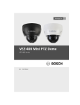
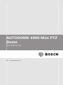
AUTODOME 4000 Mini PTZ
Dome
VEZ-400 Series
en
Operations Manual
AUTODOME 4000 Mini
PTZ Dome
Table of Contents | en
3
Table of contents
1
Safety
5
1.1
Safety precautions
5
1.2
Important safety instructions
6
1.3
Important notices
8
1.4
FCC & ICES compliance
12
1.5
Bosch notices
15
2
Description
17
2.1
Features
17
3
Unpacking
19
3.1
Parts List
19
3.2
Additional Tools Required
21
3.3
Accessories
21
4
Installation Overview
24
5
Installing a Surface Mount
25
6
Connection
29
6.1
RS-485 Connections
31
6.2
Video Connection
33
6.3
Alarm Connections
33
6.4
Power Connections
35
6.5
Camera Settings
35
6.5.1
Setting the address (ID) of the camera
37
6.5.2
Setting the protocol of the camera
37
7
On-Screen Display (OSD) Menu
39
7.1
Basic Navigation and Common Actions
39
7.2
Main Menu
42
7.2.1
Editing Titles
43
7.2.2
Clearing Saved Functions
44
7.3
System Setup Menu
45
7.3.1
System Information
45
7.3.2
Reboot
46
7.3.3
Initialize
47
7.3.4
Password
48
7.4
Display Setup
49
Bosch Security Systems, Inc.
2013.04 | |
4
en | Table of Contents
AUTODOME 4000 Mini
PTZ Dome
7.4.1
OSD Setup
49
7.4.2
Privacy Zone
51
7.4.3
Image Setup
52
7.4.4
Motion/Face Detection
53
7.4.5
Language
54
7.5
Camera Setup
55
7.5.1
Focus/Zoom
55
7.5.2
WB Setup
56
7.5.3
AE Setup
58
7.5.4
D/N Setup
59
7.5.5
Advanced
60
7.5.6
WDR/DNR
61
7.6
Dome Motion Setup
63
7.6.1
General Setup
63
7.6.2
Motion Setup
64
7.6.3
Home Action
66
7.6.4
Calibration
67
7.7
Preset Setup
68
7.8
Pattern Setup
70
7.9
Tour Setup
71
7.10
Scan Setup
72
7.11
Alarm Setup
74
8
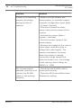
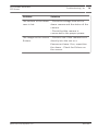
Troubleshooting
77
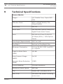
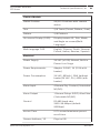
9
Technical Specifications
80
10
Dimensions
83
11
Bosch Protocol
84
12
Pelco Protocol
87
2013.04 | |
Bosch Security Systems, Inc.
AUTODOME 4000 Mini
PTZ Dome
Safety | en
5
Safety
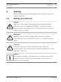
1
Before installing and operating the camera, please read this
manual carefully.
1.1
Safety precautions
Danger!
High risk: This symbol indicates an imminently hazardous
situation such as "Dangerous Voltage" inside the product.
If not avoided, this will result in an electrical shock, serious
bodily injury, or death.
Warning!
!
Medium risk: Indicates a potentially hazardous situation.
If not avoided, this could result in minor or moderate bodily
injury.
Caution!
!
Low risk: Indicates a potentially hazardous situation.
If not avoided, this could result in property damage or risk of
damage to the unit.
Notice!
This symbol indicates information or a company policy that
relates directly or indirectly to the safety of personnel or
protection of property.
Bosch Security Systems, Inc.
2013.04 | |
6
AUTODOME 4000 Mini
PTZ Dome
en | Safety
1.2
Important safety instructions
1.
Read these instructions.
2.
Keep these instructions.
3.
Heed all warnings.
4.
Follow these instructions.
5.
Do not install near any heat sources such as radiators,
heaters, stoves, or other equipment (including amplifiers)
that produce heat.
6.
Do not defeat the safety purpose of the polarized or
grounding-type plug. A polarized plug has two blades with
one wider than the other. A grounding type plug has two
blades and a third grounding prong. The wide blade or the
third prong is provided for your safety. If the provided plug
does not fit into your outlet, consult an electrician for
replacement of the obsolete outlet.
7.
Protect the power cord from being walked on or pinched,
particularly at plugs, convenience receptacles, and the
point where they exit from the apparatus.
8.
Only use attachments/accessories specified by the
manufacturer.
9.
Use only with the cart, stand, tripod, bracket, or table
specified by the manufacturer. When a cart is used, use
caution when moving the cart/apparatus combination to
2013.04 | |
Bosch Security Systems, Inc.
AUTODOME 4000 Mini
PTZ Dome
Safety | en
7
avoid injury from tip-over.
10. Unplug this apparatus during lightning storms or when l
unused for long periods of time. This will prevent damage
to the unit from lightning and power line surges.
11. Refer all servicing to qualified service personnel. Servicing
is required when the apparatus has been damaged in a way,
such as power supply cord or plug is damaged, liquid has
been spilled or objects have fallen into the apparatus, the
apparatus has been exposed to rain or moisture, does not
operate normally, or has been dropped.
Bosch Security Systems, Inc.
2013.04 | |
8
en | Safety
1.3
AUTODOME 4000 Mini
PTZ Dome
Important notices
Caution!
A regulated 24 VAC, 43W power supply is recommended for use
with this camera for the best picture and the most stable
operation. An unregulated power supply can cause damage to
the camera. When unregulated power supply is applied,
product warranty will be void.
Bosch recommends using the camera with a monitor that has a
!
CCTV-quality 75 Ohm video impedance level. If your monitor is
switched to high impedance, please adjust accordingly.
Do not attempt to disassemble the camera to gain access to the
internal components. Refer servicing to your dealer or to
qualified service personnel.
Never face the camera towards the sun or any bright or
reflective light. This may cause smear on the picture and
possible damage to the CCD.
Do not remove the serial sticker for the warranty service.
All-pole power switch - Incorporate an all-pole power switch,
with a contact separation of at least 3 mm in each pole, into the
electrical installation of the building. If it is needed to open the
housing for servicing and/or other activities, use this all-pole
switch as the main disconnect device for switching off the
voltage to the unit.
Camera grounding - For mounting the camera in potentially
damp environments, ensure to ground the system using the
ground connection of the power supply connector (see section:
Connecting external power supply).
Camera lens - An assembled camera lens in the outdoor housing
must comply and be tested in accordance with UL/IEC60065.
Any output or signal lines from the camera must be SELV or
2013.04 | |
Bosch Security Systems, Inc.
AUTODOME 4000 Mini
PTZ Dome
Safety | en
9
Limited Power Source. For safety reasons, the environmental
specification of the camera lens assembly must be within the
environmental specification of -10 °C (14 °F) to 50 °C (122 °F).
Camera signal - Protect the cable with a primary protector if the
camera signal is beyond 140 feet, in accordance with NEC800
(CEC Section 60).
Coax grounding:
–
Ground the cable system if connecting an outside cable
system to the unit.
–
Connect outdoor equipment to the unit's inputs only after
this unit has had its grounding plug connected to a
grounded outlet or its ground terminal is properly
connected to a ground source.
–
Disconnect the unit's input connectors from outdoor
equipment before disconnecting the grounding plug or
grounding terminal.
–
Follow proper safety precautions such as grounding for any
outdoor device connected to this unit.
U.S.A. models only - Section 810 of the National Electrical Code,
ANSI/NFPA No.70 provides information regarding proper
grounding of the mount and supporting structure, grounding of
the coax to a discharge unit, size of grounding conductors,
location of discharge unit, connection to grounding electrodes,
and requirements for the grounding electrode.
Bosch Security Systems, Inc.
2013.04 | |
10
AUTODOME 4000 Mini
PTZ Dome
en | Safety
Disposal - Your Bosch product was developed and
manufactured with high-quality material and
components that can be recycled and reused. This
symbol means that electronic and electrical
appliances, which have reached the end of their
working life, must be collected and disposed of
separately from household waste material. Separate
collecting systems are usually in place for disused
electronic and electrical products. Please dispose of
these units at an environmentally compatible
recycling facility, per European Directive 2002/96/EC.
Electronic Surveillance - This device is intended for use in
public areas only. U.S. federal law strictly prohibits surreptitious
recording of oral communications.
Environmental statement - Bosch has a strong commitment
towards the environment. This unit has been designed to
respect the environment as much as possible.
Electrostatic-sensitive device - Use proper CMOS/MOS-FET
handling precautions to avoid electrostatic discharge. NOTE:
Wear required grounded wrist straps and observe proper ESD
safety precautions when handling the electrostatic-sensitive
printed circuit boards.
Fuse rating - For protection of the device, the branch circuit
protection must be secured with a maximum fuse rating of 16A.
This must be in accordance with NEC800 (CEC Section 60).
Moving - Disconnect the power before moving the unit. Move
the unit with care. Excessive force or shock may damage the
unit and the hard disk drives.
Outdoor signals - The installation for outdoor signals, especially
regarding clearance from power and lightning conductors and
transient protection, must be in accordance with NEC725 and
NEC800 (CEC Rule 16-224 and CEC Section 60).
Permanently connected equipment - Incorporate a readilyaccessible disconnect device in the building installation wiring.
2013.04 | |
Bosch Security Systems, Inc.
AUTODOME 4000 Mini
PTZ Dome
Safety | en
11
Pluggable equipment - Install the socket outlet near the
equipment so that it is easily accessible.
Power resupply - If the unit is forced to power down due to
exceeding the specified operating temperatures, disconnect the
power cord, wait for at least 30 seconds, and then reconnect
the power cord.
Power lines: Do not locate the camera near overhead power
lines, power circuits, or electrical lights, nor where it may
contact such power lines, circuits, or lights.
Rack mount
–
Ventilation - Do not place this unit in a built-in installation
or rack without proper ventilation or adhering to the
manufacturer’s instructions. The equipment must not
exceed its maximum operating temperature requirements.
–
Mechanical loading - Properly mount the equipment in a
rack to prevent a hazardous condition due to uneven
mechanical loading.
SELV - All the input/output ports are Safety Extra Low Voltage
(SELV) circuits. SELV circuits should only be connected to other
SELV circuits.
Because the ISDN circuits are treated like telephone-network
voltage, avoid connecting the SELV circuit to the Telephone
Network Voltage (TNV) circuits.
The system ground is only used to comply with safety standards
or installation practices in certain countries. Bosch does not
recommend connecting system ground to safety ground unless
it is explicitly required. However, if the system ground and
safety ground are connected and grounding loops are causing
interference in the video signal, use an isolation transformer
(available separately from Bosch).
Caution!
!
Connecting System ground to Safety ground may result in
ground loops that can disrupt the CCTV system.
Bosch Security Systems, Inc.
2013.04 | |
12
AUTODOME 4000 Mini
PTZ Dome
en | Safety
Video loss - Video loss is inherent to digital video recording;
therefore, Bosch Security Systems cannot be held liable for any
damage that results from missing video information. To minimize
the risk of lost digital information, Bosch Security Systems
recommends multiple, redundant recording systems, and a
procedure to back up all analog and digital information.
1.4
FCC & ICES compliance
FCC & ICES Information
(U.S.A. and Canadian Models Only)
This device complies with part 15 of the FCC Rules. Operation is
subject to the following conditions:
–
this device may not cause harmful interference, and
–
this device must accept any interference received, including
interference that may cause undesired operation.
This equipment has been tested and found to comply with the
limits for a Class A digital device, pursuant to Part 15 of the FCC
Rules and ICES-003 of Industry Canada. These limits are designed
to provide reasonable protection against harmful interference
when the equipment is operated in a commercial environment.
This equipment generates, uses, and radiates radio frequency
energy and, if not installed and used in accordance with the
instructions, may cause harmful interference to radio
communications. However, there is no guarantee that
interference will not occur in a particular installation. In a
domestic environment, this product may cause radio
interference, in which case the user may be required to take
adequate measures. If this equipment does cause harmful
interference to radio or television reception, which may be
determined by turning the equipment off and on, the user is
encouraged to try to correct the interference by one or more of
the following measures:
–
reorient or relocate the receiving antenna;
–
increase the separation between the equipment and
receiver;
2013.04 | |
Bosch Security Systems, Inc.
AUTODOME 4000 Mini
PTZ Dome
–
Safety | en
13
connect the equipment into an outlet on a circuit different
from that to which the receiver is connected;
–
consult the dealer or an experienced radio/TV technician
for help.
Intentional or unintentional modifications, not expressly
approved by the party responsible for compliance, shall not be
made. Any such modifications could void the user's authority to
operate the equipment. If necessary, the user should consult the
dealer or an experienced radio/television technician for
corrective action.
The user may find the following booklet, prepared by the
Federal Communications Commission, helpful: How to Identify
and Resolve Radio-TV Interference Problems. This booklet is
available from the U.S. Government Printing Office, Washington,
DC 20402, Stock No. 004-000-00345-4.
Informations FCC et ICES
(modèles utilisés aux États-Unis et au Canada uniquement)
Ce produit est conforme aux normes FCC partie 15. la mise en
service est soumises aux deux conditions suivantes :
–
cet appareil ne peut pas provoquer d'interférence nuisible
et
–
cet appareil doit pouvoir tolérer toutes les interférences
auxquelles il est soumit, y compris les interférences qui
pourraient influer sur son bon fonctionnement.
Suite à différents tests, cet appareil s’est révélé conforme aux
exigences imposées aux appareils numériques de Classe A en
vertu de la section 15 du règlement de la Commission fédérale des
communications des États-Unis (FCC), et en vertu de la norme
ICES-003 d’Industrie Canada. Ces cexigences visent à fournir
une protection raisonnable contre les interférences nuisibles
quand l'appareil est utilisé dans un environment commercial.
Cet appareil génère, utilise et émet de l'energie de fréquence
radio, et peut, en cas d'installation ou d'utilisation non conforme
aux instructions, engendrer des interférences nuisibles aux
radiocommunications. Toutefois, rien ne garantit l'absence
Bosch Security Systems, Inc.
2013.04 | |
14
AUTODOME 4000 Mini
PTZ Dome
en | Safety
d'interférences dans une installation particulière. L’utilisation de
ce produit dans une zone résidentielle peut provoquer des
interférences nuisibles. Le cas échéant, l’utilisateur devra
remédier à ces interférences à ses propres frais. Il est possible
de déterminer la production d'interférences en mettant
l'appareil successivement hors et sous tension, tout en
contrôlant la réception radio ou télévision. L'utilisateur peut
parvenir à éliminer les interférences éventuelles en prenant une
ou plusieurs des mesures suivantes:
–
Modifier l'orientation ou l'emplacement de l'antenne
réceptrice;
–
Éloigner l'appareil du récepteur;
–
Brancher l'appareil sur une prise située sur un circuit
différent de celui du récepteur;
–
Consulter le revendeur ou un technicien qualifié en radio/
télévision pour obtenir de l'aide.
Toute modification apportée au produit, non expressément
approuvée par la partie responsable de l'appareil, est
strictement interdite. Une telle modification est susceptible
d'entraîner la révocation du droit d'utilisation de l'appareil.
Au besoin, l’utilisateur consultera son revendeur ou un
technicien qualifié en radio/télévision, qui procédera à une
opération corrective.
La brochure suivante, publiée par la Commission fédérale des
communications (FCC), peut s’avérer utile : How to Identify and
Resolve Radio-TV Interference Problems (Comment identifier et
résoudre les problèmes d’interférences de radio et de
télévision). Cette brochure est disponible auprès du U.S.
Government Printing Office, Washington, DC 20402, États-Unis,
sous la référence n° 004-000-00345-4.
2013.04 | |
Bosch Security Systems, Inc.
AUTODOME 4000 Mini
PTZ Dome
1.5
Safety | en
15
Bosch notices
Danger!
TO REDUCE THE RISK OF ELECTRIC SHOCK, DO NOT REMOVE
COVER (OR BACK). NO USER-SERVICEABLE PARTS INSIDE.
REFER SERVICING TO QUALIFIED SERVICE PERSONNEL.
Caution!
!
This is a Class A product. In a domestic environment, this
product may cause radio interference, in which case the user
may be required to take adequate measures.
Disclaimer
Underwriter Laboratories Inc. ("UL") has not tested the
performance or reliability of the security or signaling aspects of
this product. UL has only tested fire, shock and/or casualty
hazards as outlined in UL’s Standard(s) for Safety for Audio,
Video and Similar Electronic Apparatus - Safety Requirements
(UL 60065). UL Certification does not cover the performance or
reliability of the security or signaling aspects of this product.
UL MAKES NO REPRESENTATIONS, WARRANTIES, OR
CERTIFICATIONS WHATSOEVER REGARDING THE
PERFORMANCE OR RELIABILITY OF ANY SECURITY- OR
SIGNALING-RELATED FUNCTIONS OF THIS PRODUCT.
Copyright
This manual is the intellectual property of Bosch Security
Systems and is protected by copyright. All rights reserved.
Trademarks
All hardware and software product names used in this document
are likely to be registered trademarks and must be treated
accordingly.
Bosch Security Systems, Inc.
2013.04 | |
16
en | Safety
AUTODOME 4000 Mini
PTZ Dome
Note:
This manual has been compiled with great care and the
information it contains has been verified thoroughly. The text
was complete and correct at the time of printing. The ongoing
development of products means that the content can change
without notice. Bosch Security Systems accepts no liability for
damage resulting directly or indirectly from faults,
incompleteness or discrepancies between this manual and the
product described.
More information
For more information please contact the nearest Bosch Security
Systems location or visit www.boschsecurity.com
2013.04 | |
Bosch Security Systems, Inc.
AUTODOME 4000 Mini
PTZ Dome
2
Description | en
17
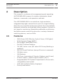
Description
This manual is a reference for programming and operating
AUTODOME 4000 camera. It contains information about
features, commands, and operation methods.
The AUTODOME 4000 is an autofocus, high-resolution,
integrated day/night camera that is part of a larger building
block for any surveillance/security system. By using multiple
keyboard controllers and multiple dome cameras, no place is
too large for monitoring. Extensible andflexible architecture
facilitates remote control functions for a variety of external
switching devices, such as DVRs.
2.1
Features
–
260X Zoom (26X Effective Optical Zoom, 10X Digital)
–
Wide Dynamic Range (WDR)
–
Day & Night (Auto/BW/Color)
–
Pan 360° Endless Rotation
–
Tilt 180° Vector scan (90° when 3D Privacy Masking is
enabled)
–
99/210 Preset Positions (except Short-cut command)
–
2/8 Auto scans
–
2/8 Patterns
–
2/8 Tours (consisting of Presets, Patterns, and Scans)
–
4 Alarm inputs, 1 Alarm output (Off/N.C./N.O.)
–
Programmable PTZ Speed: Proportional to Zoom ratio,
changeable preset speed
–
OSD with multiple display languages
–
Privacy mask zones
Bosch Security Systems, Inc.
2013.04 | |
18
en | Description
AUTODOME 4000 Mini
PTZ Dome
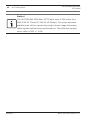
Notice!
The AUTODOME 4000 Mini PTZ Dome uses a 30X zoom lens
(fW=3.49 ±0.17mm fT=104.02 ±5.20mm). The polycarbonate
bubble (part of the camera housing) causes image distortion,
reducing the optical zoom performance. The effective optical
zoom ratio is 26X +/- 10%.
2013.04 | |
Bosch Security Systems, Inc.
AUTODOME 4000 Mini
PTZ Dome
3
Unpacking | en
19
Unpacking
This equipment should be unpacked and handled with care. If an
item appears to have been damaged in shipment, notify the
shipper immediately.
The original packing carton is the safest container in which to
transport the unit and must be used to return the unit for
service. Save it for possible future use.
Verify that all the parts listed in the Parts List are included. If
any items are missing, notify your Bosch Security Systems Sales
or Customer Service Representative.
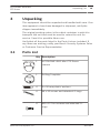
3.1
Parts List
Qty Description
1
AUTODOME 4000 Mini PTZ Dome
camera
1
Drilling Template
4
6 x 30 mm plastic anchors
4
#8 x 32 screws and attached O-rings
4
M4 x 12 Torx screws and attached Orings
Bosch Security Systems, Inc.
2013.04 | |
20
AUTODOME 4000 Mini
PTZ Dome
en | Unpacking
Qty Description
1
T20 Security Torx wrench
1
User Manual (this booklet)
Warning!
Make sure that appropriate mounting screws, rubber O-rings,
!
and anchors are used for the surface to which the camera is
mounted. The supplied plastic anchors and mounting screws
are only suitable for mounting the camera on a concrete ceiling.
2013.04 | |
Bosch Security Systems, Inc.
AUTODOME 4000 Mini
PTZ Dome
3.2
Unpacking | en
21
Additional Tools Required
–
No. 2 Phillips screwdriver
–
Drill with appropriate bit for pre-drilling anchor holes
–
Appropriate tool for cutting a hole in drywall or ceiling tile
(if applicable)
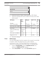
3.3
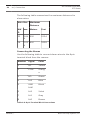
Accessories
The following accessories are available for the camera:
Bosch Security Systems, Inc.
2013.04 | |
22
AUTODOME 4000 Mini
PTZ Dome
en | Unpacking
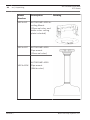
Model
Description
Drawing
Number
VEZ-A4-IC
AUTODOME 4000 Inceiling Mount
(Charcoal color and
white color ceiling
plate included)
VEZ-A4-PC
AUTODOME 4000
Pipe mount
(Charcoal color)
AUTODOME 4000
VEZ-A4-PW
Pipe mount
(White color)
2013.04 | |
Bosch Security Systems, Inc.
AUTODOME 4000 Mini
PTZ Dome
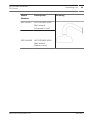
Model
Unpacking | en
Description
23
Drawing
Number
VEZ-A4-WC
AUTODOME 4000
Wall mount
(Charcoal color)
VEZ-A4-WW AUTODOME 4000
Wall mount
(White color)
Bosch Security Systems, Inc.
2013.04 | |
24
AUTODOME 4000 Mini
PTZ Dome
en | Installation Overview
4
Installation Overview
The AUTODOME 4000 camera comes with the hardware and
installation instructions necessary to mount the camera to a
concrete ceiling.
This following mounting accessories are available (and are
supplied with separate mounting instructions):
–
Wall mount, used in applications where the camera is
–
Pipe mount, used in applications where the camera is
mounted to a vertical wall.
mounted to a horizontal (high) ceiling.
–
In-ceiling mount, used in applications where the camera is
mounted into a recessed ceiling.
The installation should be made by qualified installation
personnel and conform to the National Electrical Code and
applicable local codes.
2013.04 | |
Bosch Security Systems, Inc.
AUTODOME 4000 Mini
PTZ Dome
5
Installing a Surface Mount | en
25
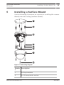
Installing a Surface Mount
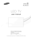
Use the following illustration as a guide for installing the camera
directly onto the ceiling (surface mount):
Figure 5.1: Mounting diagram
Numbe Description
r
1
Drilling template
2
6 x 30 mm plastic anchor
Bosch Security Systems, Inc.
2013.04 | |
26
AUTODOME 4000 Mini
PTZ Dome
en | Installing a Surface Mount
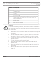
Numbe Description
r
3
Camera base
4
O-ring
5
#8 x 32 screw
6
Safety strap (will hold item #7 dome cover for
easy installation)
7
Dome cover
8
M4 x 12 Torx screw
Caution!
!
To prevent humidity problems, the camera must be installed in
dry conditions, and the cable leads should be sealed after they
are connected.
1.
Determine a secure location that can support the weight of
the dome.
2.
Use the template (refer to , page 25, item 1) to mark the
locations of the four screw holes and the cable conduit.
3.
Pre-drill the four screw holes wide enough to accept the
plastic anchors.
4.
Cut out the entire cable conduit hole.
5.
Insert the four plastic anchors (item 2) inside the predrilled holes.
6.
Route the cables from the camera through the conduit in
the ceiling.
7.
Remove the dome cover (item 6) from the camera base
(item 3).
2013.04 | |
Bosch Security Systems, Inc.
AUTODOME 4000 Mini
PTZ Dome
Installing a Surface Mount | en
27
Notice!
To prevent scratches on the dome cover, Do Not Remove the
plastic film protecting the dome cover until after hardware
installation is complete.
8.
Remove the white foam ring from the camera base, and
remove the white foam sheet from the inside of the dome
cover. (These are for protection during transport.)
9.
Align the four screw holes on the camera base (item 3) with
the four plastic anchors.
Caution!
!
When (re)mounting the camera base, make sure that each
mounting screw has a rubber O-ring. This ensures protection
against water ingress.
10. Attach the camera base to the ceiling using the four #8 x 32
screws (with O-rings attached) (item 4). Tighten the screws
enough to ensure that the camera base is secured to the
ceiling.
11. Make the necessary Dip Switch settings (described in
chapter 4.3). Note: This step can also be done later, but
then the dome cover must be re-opened.
Caution!
When (re)mounting the dome cover to the camera base, make
!
sure that each screw has a rubber O-ring, and that the large
rubber O-ring is in place on the camera base. This ensures
protection against water ingress.
12. Align the screw holes on the dome cover (item 6) with the
camera base.
13. Attach the dome cover to the camera base using the four
M4 x 12 Torx screws (with O-rings (item 4) attached) using
the supplied Torx wrench. Make sure that the large rubber
O-ring between the camera base and dome cover is in place
Bosch Security Systems, Inc.
2013.04 | |
28
en | Installing a Surface Mount
AUTODOME 4000 Mini
PTZ Dome
to protect the camera against water ingress. Tighten the
screws enough to ensure that the housing is secured to the
camera base and that the rubber O-rings seal the dome
cover against water ingress.
14. Remove the plastic film protecting the dome cover from
scratches.
2013.04 | |
Bosch Security Systems, Inc.
AUTODOME 4000 Mini
PTZ Dome
Connection | en
29
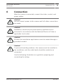
Connection
6
After the camera is mounted, connect the video, control, and
power cables.
Caution!
!
Do not connect power to the camera until all other connections
are made.
Caution!
!
Installation should only be performed by qualified service
personnel in accordance with the National Electrical Code or
applicable local codes.
Caution!
!
All wires for installation applications must be routed through a
grounded conduit.
Caution!
!
To prevent humidity problems, the camera must be installed in
dry conditions, and the cable leads should be sealed once
connected.
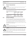
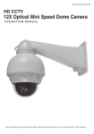
Use the following illustration as a guide for preparing and
connecting the wiring:
Bosch Security Systems, Inc.
2013.04 | |
30
AUTODOME 4000 Mini
PTZ Dome
en | Connection
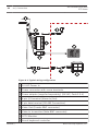
Figure 6.1: Typical wiring configuration
1 24 VAC Power In
2 Power connector with screw terminals
3 Power adapter (supplied separately) (24 VAC, Peak 2.5 A)
4 8-pin I/O terminal (Alarm In/Out)
5 2-pin data terminal (RS-485 Connection)
6 Video Out (Female BNC connector)
7 Video In to monitor (Male BNC connector)
8 CCTV Monitor
9 Bosch keyboard controller
2013.04 | |
Bosch Security Systems, Inc.
AUTODOME 4000 Mini
PTZ Dome
Connection | en
31
Note: The box around several objects in the graphic above
indicates that those devices are supplied separately.
6.1
RS-485 Connections
The camera can be controlled by an external device or control
system using an RS-485 duplexer. The total length of the cable
for communication should not exceed 1 km (3937 ft). If the
distance between the camera and the control room is greater
than 1 km (3937 ft), Bosch recommends using a repeater (not
supplied).
Notice!
The wire shield must be tied to signal at both ends, if 2-wire
twisted pair is used.
Notice!
When the RS-485 signal is looped through, ensure that (only)
the last device is terminated properly. Improper RS-485 wiring
or termination may result in unreliable system operation.
Use a 2-wire (shielded), half-duplex, differential, multi-drop with
the following attributes:
Wire Type
2-wire Shielded Twisted Pair
Distance
1.2 Km (3937 ft)
Gauge
0.511 mm (24 AWG)
Impedance
120 Ω
Table 6.1: RS-485 Wire Specifications
The following table shows the terminal connections for the 2-pin
terminal block RS-485 connections (see , page 30, item 5):
Bosch Security Systems, Inc.
2013.04 | |
32
AUTODOME 4000 Mini
PTZ Dome
en | Connection
Number
Signal
Color
1
TRX +
Sky
2
TRX -
White
Table 6.2: 2-pin Terminal Block Connections
Notice!
When the camera's RS-485 port is connected to a MIC-BP3
Biphase convertor, the camera's TRX+ should be connected to
the convertor's RxB, and TRX- should be connected to RxA. The
camera's baud rate should be set to 9600, and the protocol
should be set to Bosch OSRD. Also make sure that the camera
ID is configured correctly. For further details on setting up the
MIC-BP3, please refer to the separate MIC-BP3 Bi-Phase
Converter Card Installation and Operation Manual.
2013.04 | |
Bosch Security Systems, Inc.
AUTODOME 4000 Mini
PTZ Dome
6.2
Connection | en
33
Video Connection
Coaxial cable terminated with a male BNC connector is the most
common method for transmitting composite video from the
camera to a monitor. If the head end device features built in
video termination then no termination connector is needed.
Size
O.D. between 4.6 mm (0.181 in.) and 7.9
mm (0.312 in.)
Shield
Copper braid: 95%
Central Conductor Standard copper center
Terminal
Male BNC
Connector
Table 6.3: Recommended Coax Specifications
Connecting the Video
To connect the video, do the following:
1.
Terminate the coaxial cable from the head end system with
a male BNC connector. Alternately, switch the head end
system to 75 Ohm termination.
2.
Connect the male BNC connector to the Video Out female
BNC connector from the base of the camera.
6.3
Alarm Connections
The camera provides four alarm inputs and one alarm output.
Each input can be activated by dry contact devices such as
pressure pads, passive infrared detectors, door contacts, and
similar devices. The alarm output can activate an external
device, such as a buzzer.
Wire alarms either Normally Open (N.O.) or Normally Closed
(N.C.); you must program the alarm inputs N.O. (the default) or
N.C. through the on-screen display menus.
Bosch Security Systems, Inc.
2013.04 | |
34
AUTODOME 4000 Mini
PTZ Dome
en | Connection
The following table summarizes the maximum distances for
alarm wires:
Wire Size
Maximum
Distance
AW
mm
Meters
Feet
0.64
500
152.4
800
243.8
G
22
4
18
1.02
4
Connecting the Alarms
Use the following table to connect alarm wires to the 8-pin
terminal block from the camera:
Number
Signal
Color
1
NC
Yellow
2
COM
Orang
e
3
NO
Green
4
AL3
Blue
5
GND
Black
ALM
6
AL2
Violet
7
AL1
Gray
8
AL0
Brown
Table 6.4: 8-pin Terminal Block Connections
2013.04 | |
Bosch Security Systems, Inc.
AUTODOME 4000 Mini
PTZ Dome
Connection | en
35
Power Connections
6.4
Caution!
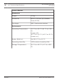
!
The camera unit accepts 24 VAC power only. Do not connect
120 V or 230 V to this camera!
The recommended power cable is a 2-conductor, 14-18 gauge
cable, depending on the distance.
A/W
6.5
14 AWG 16AWG
18 AWG
(2.5
(1.5
(1.0
mm)
mm)
mm)
2 A / 43 W (with
250 m
150 m
100 m
heater)
(820 ft)
(492 ft)
(328 ft)
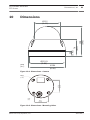
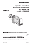
Camera Settings
The camera can communicate with external switching devices
such as a multiplexer or a DVR by setting the Rotary and Dip
switches. Refer to the tables below for setting the camera’s ID
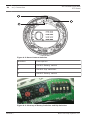
and selecting the protocol. The camera's Dip switches can be
accessed by removing the dome cover, and are located on a PCB
attached to the camera base.
Caution!
!
To prevent humidity problems, the camera’s dome cover must
be removed only in dry conditions.
Caution!
When (re)mounting the dome cover to the camera base, ensure
!
that each screw has a rubber O-ring, and that the large rubber
O-ring is in place on the camera base. This ensures protection
against water ingress.
Bosch Security Systems, Inc.
2013.04 | |
36
AUTODOME 4000 Mini
PTZ Dome
en | Connection
Figure 6.2: Dome Camera Switches
Number
Description
1
SW301 Rotary switch
2
SW303 Dip switches
3
SW302 Rotary switch
Figure 6.3: Close-up of Rotary Switches and Dip Switches
2013.04 | |
Bosch Security Systems, Inc.
AUTODOME 4000 Mini
PTZ Dome
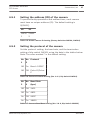
6.5.1
Connection | en
37
Setting the address (ID) of the camera
To prevent faulty operations and malfunctions, each camera
must have an unique address (ID). The default setting is
0[ID001].
X0
X1
SW30 SW30
1
2
Table 6.5: Dome Camera ID Setting (Rotary Switches SW301, SW302)
6.5.2
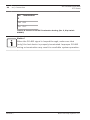
Setting the protocol of the camera
Set the protocol setting, the baud rate, and the termination
setting of dip switch SW303, using the data in the tables below.
Note: The value marked * is the default setting.
No No Protocol
1
2
Off On Bosch OSRD*
Off Off Pelco-D/PelcoP
Table 6.6: Camera Protocol Setting (No. 1 & 2, Dip Switch SW303)
No No Baud Rate
3
4
(bps)
Off Off 2400
Off On 4800
On Off 9600*
On On 38400
Table 6.7: Camera Baud Rate Setting (No. 3 & 4, Dip Switch SW303)
Bosch Security Systems, Inc.
2013.04 | |
38
en | Connection
AUTODOME 4000 Mini
PTZ Dome
No Termination
5
Off Off
On On*
Table 6.8: Camera’s RS-485 Termination Setting (No. 5, Dip Switch
SW303)
Notice!
When the RS-485 signal is looped through, make sure that
(only) the last device is properly terminated. Improper RS-485
wiring or termination may result in unreliable system operation.
2013.04 | |
Bosch Security Systems, Inc.
AUTODOME 4000 Mini
PTZ Dome
7
On-Screen Display (OSD) Menu | en
39
On-Screen Display (OSD) Menu
Notice!
Before beginning this section of the manual, you must install
and connect the camera to an interface device. Refer to the
Mounting Manual. Once you have installed the camera, apply
power to the camera.
When the camera is powered-up, the start-up screen appears on
the monitor.
VEZ-400 MINI PTZ
DOME
RS-485/9600
ID001
CAM TEST ...PASS
7.1
Basic Navigation and Common Actions
Camera operators can operate the camera by two methods:
–
Use of hot keys [Refer to Bosch Protocol, page 84].
–
Use of the OSD Menu displayed on the monitor [Continue
to read this chapter].
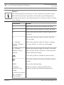
The following table identifies the symbols that depict actions of
the joystick controller, or the keys on the keyboard, that control
the camera.
Bosch Security Systems, Inc.
2013.04 | |
40
AUTODOME 4000 Mini
PTZ Dome
en | On-Screen Display (OSD) Menu
Notice!
The step-by-step instructions in this chapter are written with
the idea that camera operators know the joystick/keyboard
commands (listed in the table below) for actions (Select, Clear,
Save, Exit).
Command
Action
▲
Move the joystick up to select an item.
▼
Move the joystick down to select an item.
◄
Move the joystick left to select options for
an item.
►
Move the joystick right to select options
for an item.
► / [Open]
Move the joystick right to select, change,
button / [Near]
or save values, or to go to edit pages.
button
► / [Close]
Move the joystick right to cancel or to exit
button / [Far]
the current menu. (Return to the previous
button
menu without saving.)
Turn the joystick clockwise (zoom tele).
Turn the joystick counterclockwise (zoom
wide).
[KEY]
Press the defined key.
In Bosch
Stop an action; camera switches to
protocol: Aux
manual mode and pauses temporarily.
code;
In Pelco protocol:
96 + Preset or
ESC button
2013.04 | |
Bosch Security Systems, Inc.
AUTODOME 4000 Mini
PTZ Dome
On-Screen Display (OSD) Menu | en
41
Notice!
You must save each state after each step of the submenu or
the edit menu upon editing functions or changing settings.
You may need to save settings for one function twice. For
example, after {the position or the title of a Preset} is saved at
the ‘Sub Menu’, {the status of the Preset Setup} must be saved
at the ‘Preset Setup Menu’ again.
Bosch Security Systems, Inc.
2013.04 | |
42
en | On-Screen Display (OSD) Menu
7.2
AUTODOME 4000 Mini
PTZ Dome
Main Menu
The MAIN MENU provides access to all programmable settings
for the camera.
When you use Pelco-D and Pelco-P protocol with your controller,
you can access the MAIN MENU on your monitor by pressing the
keys [95] + [Preset], or by pressing and holding the [Menu] key
for 2 seconds.
When you use Bosch OSRD protocol with your controller, you
can access the MAIN MENU on your monitor by pressing the
keys [ON]+[46]+[Enter].
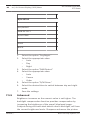
MAIN MENU
SYSTEM SETUP
DISPLAY SETUP
CAMERA SETUP
DOME MOTION
PRESET SETUP
PATTERN SETUP
TOUR SETUP
SCAN SETUP
ALARM SETUP
EXIT
MAIN MENU Choices
2013.04 | |
Bosch Security Systems, Inc.
AUTODOME 4000 Mini
PTZ Dome
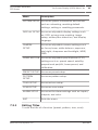
Menu
On-Screen Display (OSD) Menu | en
43
Description
SYSTEM SETUP Accesses system information and actions
such as: rebooting, resetting default
settings, setting or resetting passwords.
DISPLAY SETUP Accesses adjustable display settings such
as: OSD, privacy zone masking, image
setup, motion/face detection, and display
language.
CAMERA
Accesses adjustable camera settings such
SETUP
as: focus/zoom, white balance, exposure,
day/night, sharpness and backlight, WDR/
DNR.
DOME MOTION Accesses adjustable pan/tilt/zoom (PTZ)
settings such as: preset speed, autoflip,
proportional pan/tilt, home preset, and
calibration.
PRESET SETUP
Accesses preset setup.
PATTERN
Accesses pattern setup.
SETUP
TOUR SETUP
Accesses tour setup.
SCAN SETUP
Accesses scan setup.
ALARM SETUP
Accesses the alarm settings such as: inputs,
outputs, and rules.
EXIT
7.2.1
Exits the menu.
Editing Titles
To edit the title of a function (preset, pattern, tour, scan):
Bosch Security Systems, Inc.
2013.04 | |
44
AUTODOME 4000 Mini
PTZ Dome
en | On-Screen Display (OSD) Menu
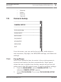
4
From the MAIN MENU, move the joystick to the right
(setup menu of preset, pattern, tour, and scan). Move the
joystick to the right again to select the Title menu. The
screen TITLE appears.
TITLE
ABCDEFGHIJKLMNOPQRSTUVWXYZ0
123456789/+-=;?#.,"~0
SELECT: (MOVE)
SET/CLEAR: (TELE/WIDE)
SAVE: (NEAR)
EXIT: (FAR)
1.
Move the joystick right, left, up, or down to select a
character.
2.
Press the button [Tele] to input a character. Note: To
cancel a character, press the [Wide] button.
3.
When you finish entering the title, save the title. Note: To
cancel the selected title, use the [Far] button to return to
the previous menu.
7.2.2
Clearing Saved Functions
To clear (delete) individual, saved functions:
1.
Select a function in any menu (PRESET/TOUR/PATTERN/
SCAN/ALARM).
2013.04 | |
2.
Move the joystick right. Select Clear.
3.
If necessary, follow additional prompts.
Bosch Security Systems, Inc.
AUTODOME 4000 Mini
PTZ Dome
4.
7.3
On-Screen Display (OSD) Menu | en
45
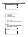
Save the settings.
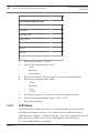
System Setup Menu
SYSTEM SETUP
INFO.
REBOOT
INITIALIZE
5.1
PROTOCOL LOG
PASSWORD
EXIT
From this menu, you can display system information, reboot the
system, restore default settings (initialize), and set a password.
7.3.1
System Information
System Information displays details about the Model Name/
Running Version/Protocol/Communication Type/Camera ID No./
System. It is only for reference; you cannot make changes here.
To display the System Information screen:
1.
From the MAIN MENU, select SYSTEM SETUP. The
submenu SYSTEM SETUP appears.
2.
Select INFO.. The screen SYSTEM INFORMATION appears.
Bosch Security Systems, Inc.
2013.04 | |
46
en | On-Screen Display (OSD) Menu
AUTODOME 4000 Mini
PTZ Dome
SYSTEM INFORMATION
VEZ-400 MINI PTZ DOME
VEZ4 SPD V1.0.0
VEZ4 CAM V1.0.0
RS485/9600
ID001
PAL
-Exit: (FAR)
4
Note the system information displayed. Note: The camera
ID changes depending on settings.
7.3.2
Reboot
Reboot the system if there are any problems with controlling or
operating the camera. Rebooting will recycle power without
changing camera settings. To reboot the system:
1.
From the MAIN MENU, select SYSTEM SETUP. The
submenu SYSTEM SETUP appears.
2.
Select REBOOT. The screen REBOOT appears.
REBOOT
CONTINUE?
YES: NEAR
NO: FAR
2013.04 | |
Bosch Security Systems, Inc.
AUTODOME 4000 Mini
PTZ Dome
7.3.3
On-Screen Display (OSD) Menu | en
1.
Select the option "Yes."
2.
Select the value "Near." The system reboots.
47
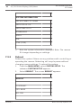
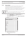
Initialize
Initialize the system to restore some or all of the camera
settings to their defaults. To initialize:
1.
From the MAIN MENU, select SYSTEM SETUP. The
2.
Select INITIALIZE. The screen INITIALIZE appears.
submenu SYSTEM SETUP appears.
INITIALIZE
ALL
CAM
PRESET
TOUR
PATTERN
SCAN
ETC
SAVE
BACK
1.
Select the function to initialize:
–
ALL: Clear All items saved in the system.
–
CAM: Clear camera-related settings.
–
PRESET: Clear all saved presets. (To clear presets
individually, refer to Preset Setup, page 68.)
–
TOUR: Clear saved Tours.
Bosch Security Systems, Inc.
2013.04 | |
48
en | On-Screen Display (OSD) Menu
AUTODOME 4000 Mini
PTZ Dome
–
PATTERN: Clear saved Patterns.
–
SCAN: Clear saved Scan items.
–
[ETC: Clear other settings except camera and PTZ
settings (CAM status and saved PRESET, TOUR,
PATTERN and SCAN).]
2.
Select the value "Clear."
3.
Save. The system restores the default settings of the
camera.
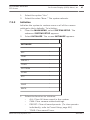
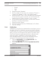
7.3.4
Password
Set a four-character password to prevent unauthorized access
and changes to the camera settings. Users/operators must enter
the valid password before programming the camera. The default
password is "0000." To set/enable a password:
1.
From the MAIN MENU, select SYSTEM SETUP. The
submenu SYSTEM SETUP appears.
2.
Select PASSWORD. The screen PASSWORD appears.
PASSWORD
CURRENT
ENABLE
NEW
CONFIRM
0123456789
-SET/CLEAR
-EXIT
1.
2013.04 | |
Select the numbers that comprise the password.
Bosch Security Systems, Inc.
AUTODOME 4000 Mini
PTZ Dome
7.4
On-Screen Display (OSD) Menu | en
49
2.
Press the key {Tele}.
3.
Select the option "Enable."
4.
Select the value "Enable." The system locks the password.
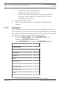
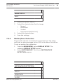
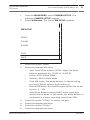
Display Setup
DISPLAY SETUP
OSD SETUP
PRIVACY ZONE
IMAGE SETUP
MOTION/FACE
LANGUAGE: [language]
EXIT
From this menu, you can set up the on-screen display, create/
edit/ delete a privacy mask, change displayed image settings,
set motion/face detection, and change the display language.
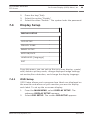
7.4.1
OSD Setup
OSD Setup allows you to program how labels are displayed on
the monitor and where on your monitor you want to display
each label. To set up the on-screen display:
1.
From the MAIN MENU, select DISPLAY SETUP. The
submenu DISPLAY SETUP appears.
2.
Select OSD SETUP. The screen OSD SETUP appears.
Bosch Security Systems, Inc.
2013.04 | |
50
en | On-Screen Display (OSD) Menu
AUTODOME 4000 Mini
PTZ Dome
OSD SETUP
LABEL POSITION
TIME
ZOOM
ID
MODE
ANGLE
SAVE
BACK
- CHANGE
- TO SETUP
1.
Select the option "Label Position" to set/change the
position of labels.
2.
Select the value "On" to display the label position.
3.
Press the button {Tele} to edit the position of labels.
4.
Use the joystick to move the label up, down, left, and/or
right.
5.
Save the option.
6.
Select any of the following labels to display:
–
Title (Label Position)
–
(Dwell) Time
–
Zoom (ratio)
–
(Camera) ID
–
(Operation) Mode
–
(PTZ) Angle
Note: You can display only selected video or characters in
the video. Each element may be configured.
2013.04 | |
Bosch Security Systems, Inc.
AUTODOME 4000 Mini
PTZ Dome
7.
7.4.2
On-Screen Display (OSD) Menu | en
51
Save the option.
Privacy Zone
A Privacy mask zone allows an administrator to program a foursided, user-defined zone which cannot be viewed by operators.
A maximum of 15 positions can be displayed on the monitor.
The mask will stay in position even with changing pan and tilt
angles, and will adjust in size according to the zoom ratio [Tele/
Wide]. Bosch recommends setting the size of the mask to be at
least twice the size (height and width) of the object being
masked. The speed of displaying masks is proportional to the
number of masks on the screen. To set a privacy mask zone:
1.
From the MAIN MENU, select DISPLAY SETUP. The
2.
Select PRIVACY ZONE. The screen PRIVACY ZONE SETUP
submenu DISPLAY SETUP appears.
appears.
PRIVACY ZONE SETUP
PRIVACY.##
EDIT
DISPLAY
WIDTH
HEIGHT
CLEAR
SAVE
BACK
Bosch Security Systems, Inc.
2013.04 | |
52
AUTODOME 4000 Mini
PTZ Dome
en | On-Screen Display (OSD) Menu
PRIVACY ZONE SETUP
- CHANGE
1.
Select the option "Privacy."
2.
Select a zone ID [00-14).
3.
Select the option "Edit."
4.
Select the value "Mask."
5.
Move to a target (Pan/Tilt) and adjust a Mask using the
joystick (Pan/Tilt, Zoom Tele or Wide).
6.
Save the position.
7.
Exit the menu Edit.
8.
Select the option "Display."
9.
Select the value "On." The mask appears.
10. Select a position.
11. Select the height (XX) and width (XX) of the mask (1~5X) to
resize the mask.
12. Save the settings.
Note: Select the option "Clear" to clear the Mask.
7.4.3
Image Setup
This menu is for changing displayed image settings. To set up
image setup:
1.
From the MAIN MENU, select DISPLAY SETUP. The
submenu DISPLAY SETUP appears.
2.
Select IMAGE SETUP. The screen IMAGE SETUP appears.
IMAGE SETUP
MIRROR
SAVE
2013.04 | |
Bosch Security Systems, Inc.
AUTODOME 4000 Mini
PTZ Dome
On-Screen Display (OSD) Menu | en
53
IMAGE SETUP
BACK
7.4.4
1.
Select the option "Mirror."
2.
Select the desired value for the image.
–
Normal
–
Horizontal
–
Vertical
–
H/V [Horizontal/Vertical]
3.
Select the desired value
4.
Save the settings.
Motion/Face Detection
Program the camera to monitor the movements of the image
and send an alarm message to the OSD in the Alarm Out action.
To set up motion/face detection:
1.
From the MAIN MENU, select DISPLAY SETUP. The
submenu DISPLAY SETUP appears.
2.
Select MOTION/FACE. The screen MOTION/FACE
DETECTION appears.
MOTION/FACE DETECTION
MD/FD
SENSITIVITY
ALARM
Bosch Security Systems, Inc.
2013.04 | |
54
en | On-Screen Display (OSD) Menu
AUTODOME 4000 Mini
PTZ Dome
MOTION/FACE DETECTION
ATIME
SAVE
BACK
1.
Select the option "MD/FD" to program motion detection
and/or face detection.
2.
–
Off
–
MD
–
FD
3.
Select the option "Sensitivity."
4.
Select the appropriate value.
5.
Select the option "Alarm."
6.
Select the appropriate value:
7.
7.4.5
Select the appropriate value:
–
OSD
–
Alarm Out
–
Both
Save the settings.
Language
To select a different display language:
1.
From the MAIN MENU, select DISPLAY SETUP. The
submenu DISPLAY SETUP appears.
2013.04 | |
2.
Select L ANGUAGE. The screen L ANGUAGE appears.
3.
Select the desired language:
–
English
–
Chinese
–
Dutch
–
French
Bosch Security Systems, Inc.
AUTODOME 4000 Mini
PTZ Dome
7.5
On-Screen Display (OSD) Menu | en
–
German
–
Italian
–
Russian
–
Spanish
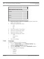
55
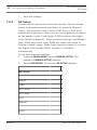
Camera Setup
CAMERA SETUP
FOCUS/ZOOM
W-BALANCE
EXPOSURE
DAY/NIGHT
ADVANCED
WDR/DNR
EXIT
From this menu, you can set the focus/zoom, white balance,
auto exposure, day/night, the WDR/DNR settings, and Advanced
settings.
7.5.1
Focus/Zoom
Auto Focus allows the lens to remain in focus during zoom-in,
zoom-out and motion functions automatically. Zoom speed
allows the user to define how fast the camera will go from full
wide zoom to the 30X optical zoom. To set focus/zoom settings:
1.
From the MAIN MENU, select CAMERA SETUP. The
submenu CAMERA SETUP appears.
2.
Select FOCUS/ZOOM. The screen FOCUS/ZOOM SETUP
appears.
Bosch Security Systems, Inc.
2013.04 | |
56
en | On-Screen Display (OSD) Menu
AUTODOME 4000 Mini
PTZ Dome
FOCUS/ZOOM SETUP
FOCUS
ZOOM SPD
D.ZOOM
SAVE
BACK
7.5.2
1.
Select the option "Focus."
2.
Select the appropriate value:
–
Auto
–
Manual
–
Semi-Auto
3.
Select the option "Zoom Spd" to set the zoom speed.
4.
Select the appropriate value:
–
Slow
–
Normal
–
Fast
–
V-Fast
5.
Select the option "D.Zoom" to set the Digital Zoom.
6.
Select the appropriate value: ON or OFF.
7.
Save the settings.
WB Setup
The WB (White Balance) feature automatically processes the
displayed image to retain color balance over different color
temperature ranges. In Manual mode, you can change the R or B
gain value to adjust the colors displayed on the monitor.
To set white balance settings:
2013.04 | |
Bosch Security Systems, Inc.
AUTODOME 4000 Mini
PTZ Dome
1.
On-Screen Display (OSD) Menu | en
57
From the MAIN MENU, select CAMERA SETUP. The
submenu CAMERA SETUP appears.
2.
Select W-Balance. The screen WB SETUP appears.
WB SETUP
MODE
R GAIN
B GAIN
SAVE
BACK
1.
Select the option "Mode."
2.
Select the appropriate value:
–
Auto Trace White balance (ATW): Aligns the white
balance automatically. (2,300 to 11,000 K)
–
Indoor: 3200 K Base Mode
–
Outdoor: 5400 K Base Mode
–
Push WB mode: The white balance is aligned during
–
Manual WB mode: Red and Blue gain values can be set
key input. (White balance push auto key)
by user, 0 ~ 255
–
Auto White Balance mode (AWB): Wide range auto
white balance mode. In this mode, the white balance is
performed at a faster operating speed than ATW.
3.
Select the option "R Gain" to set the red gain.
4.
Select the appropriate value.
5.
Select the option "B Gain."
6.
Select the appropriate value.
Bosch Security Systems, Inc.
2013.04 | |
58
en | On-Screen Display (OSD) Menu
7.
7.5.3
AUTODOME 4000 Mini
PTZ Dome
Save the settings.
AE Setup
Shutter speed controls the electronic shutter. Set the shutter
speed to operate automatically (Auto) or manually (Numeric
Value). The Automatic Gain Control (AGC Gain or AGC Max)
adjusts the brightness of the pictures. The brightness increases
as the numeric value is set higher. SSNR enhances the digital
noise reduction properly. There are three settings: Low/Middle/
High. When gain levels raise, SSNR will reduce the noise to
display a clearer image. When Input luminance level is too dark,
the Digital Slow Shutter (DSS) function is set higher
automatically.
To set auto exposure settings:
1.
From the MAIN MENU, select CAMERA SETUP. The
2.
Select EXPOSURE. The screen AE SETUP appears.
submenu CAMERA SETUP appears.
AE SETUP
MODE
SHUT
AGC GAIN
AGC MAX
DSS
BRIGHT
SAVE
2013.04 | |
Bosch Security Systems, Inc.
AUTODOME 4000 Mini
PTZ Dome
On-Screen Display (OSD) Menu | en
59
AE SETUP
BACK
1.
Select the option "Mode" (Auto Exposure (AE) Mode).
2.
Select the appropriate values (listed in the top row of the
table below):
AE Mode
Full
Manual
SHUT FIX
WD
Auto
Shutter
X
(1/1~1/100,000)
O
O
(1/1000)
(1/1000)
X
AGC Gain (00~36dB)
X
O (06dB)
X
X
AGC Max
O
X
O (High)
O
(Off/Low/Mid/High/
(default:
Super)
High)
DSS (0x2~0x128Fld)
O (Off)
X
X
X
Bright (00~15)
O (06)
X
O (06)
O
4
7.5.4
R
Save the settings.
D/N Setup
The D/N (Day/Night) function improves the camera’s sensitivity
at night or when the brightness level of the ambient
environment is low. The Day & Night filter is automatically
switched according to the luminance level. To set day/night:
1.
From the MAIN MENU, select CAMERA SETUP. The
submenu CAMERA SETUP appears.
2.
Select DAY/NIGHT. The screen D/N SETUP appears.
Bosch Security Systems, Inc.
2013.04 | |
60
en | On-Screen Display (OSD) Menu
AUTODOME 4000 Mini
PTZ Dome
D/N SETUP
DAY/NIGHT
D&N DETECT
D/N DTIME
SAVE
BACK
1.
Select the option "Day/Night."
2.
Select the appropriate value:
–
Auto
–
Day
–
Night
3.
Select the option "D&N Detect."
4.
Select the appropriate value:
–
Auto
–
Sensor
–
Video
5.
Select the option "D/N Dtime."
6.
Select the desired time to switch between day and night
mode.
7.
7.5.5
Save the settings.
Advanced
Brightness increases as the numeric value is set higher. The
backlight compensation function provides compensation by
increasing the brightness of the overall displayed image.
Subjects being shot with dark details due to backlight ,will have
the correct brightness levels. Sharpness enhances the picture
2013.04 | |
Bosch Security Systems, Inc.
AUTODOME 4000 Mini
PTZ Dome
On-Screen Display (OSD) Menu | en
61
detail by increasing the aperture gain of the camera and
sharpening the edges in the picture. To set sharpness and
backlight settings:
1.
From the MAIN MENU, select CAMERA SETUP. The
submenu CAMERA SETUP appears.
2.
Select ADVANCED. The screen ADVANCED SETUP
appears.
ADVANCED SETUP
SHARPNESS
BACKLIGHT
SAVE
BACK
7.5.6
1.
Select the option "Sharpness."
2.
Set the sharpness level.
3.
Select the option "Backlight."
4.
Select the appropriate value: ON or OFF.
5.
Save the settings.
WDR/DNR
When both high-brightness subjects and low-brightness subjects
need to be displayed at the same time, overexposure in the
high-brightness areas or a loss of dark detail in the lowbrightness areas may occur. The WDR (Wide Dynamic Range)
function creates images free from over-exposure or loss of dark
detail by combining two images from tripping the shutter for a
long exposure time and for a short exposure time in one field.
The DNR (Digital Noise Reduction) function creates ’noiseless’
Bosch Security Systems, Inc.
2013.04 | |
62
en | On-Screen Display (OSD) Menu
AUTODOME 4000 Mini
PTZ Dome
images, even in low light. In ’WDR on’ mode, unnatural color or
image, and noise, may occur in a bright area. Under special
illumination, it is better to avoid using the WDR function. To set
WDR and DNR settings:
1.
From the MAIN MENU, select CAMERA SETUP. The
submenu CAMERA SETUP appears.
2.
Select WDR/DNR. The screen WDR/DNR appears.
WDR/DNR
WDR SETUP
WDR LEVEL
DNR SETUP
DNR LEVEL
SAVE
BACK
2013.04 | |
1.
Select the option "WDR Setup."
2.
Select the value "On."
3.
Select the option "WDR Level."
4.
Set the appropriate level.
5.
Select the option "DNR Setup."
6.
Select the value "On."
7.
Select the option "DNR Level."
8.
Set the appropriate level.
9.
Save the settings.
Bosch Security Systems, Inc.
AUTODOME 4000 Mini
PTZ Dome
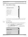
7.6
On-Screen Display (OSD) Menu | en
63
Dome Motion Setup
DOME MOTION SETUP
GENERAL SETUP
MOTION SETUP
HOME ACTION
CALIBRATION
EXIT
From this menu, you can set the general functions of the dome,
motion functions of the pan/tilt/zoom motor, the home action,
and calibration.
7.6.1
General Setup
This menu controls general functions of the camera: power-up
action, turbo speed, preset speed. To set these functions:
1.
From the MAIN MENU, select DOME MOTION. The
2.
Select GENERAL SETUP. The screen GENERAL SETUP
submenu DOME MOTION appears.
appears.
GENERAL SETUP
POWER-UP ACT.
TURBO SPEED
Bosch Security Systems, Inc.
2013.04 | |
64
en | On-Screen Display (OSD) Menu
AUTODOME 4000 Mini
PTZ Dome
GENERAL SETUP
PRESET SPEED
SAVE
BACK
1.
Select the option "Power-Up Act." The power-up action sets
the function (preset, tour, pattern, and scan) that the
system should perform when the power is cycled or after
an alarm action.
2.
Select the value "On" so that the system will resume its
prior activity after an alarm or a power failure.
3.
Select the option "Turbo Speed." This defines the pan and
tilt speed during manual operation of Pan/Tilt only.
4.
Select the appropriate value: ON or OFF.
5.
Select the option "Preset Speed." This sets the speed when
moving to a predefined preset.
6.
7.
7.6.2
Select the appropriate value:
–
Fast
–
Normal
–
Slow
Save the settings.
Motion Setup
This menu controls camera settings such as proportional pan/
tilt, auto flip, and over tilt. To set these functions:
1.
From the MAIN MENU, select DOME MOTION. The
submenu DOME MOTION appears.
2.
Select MOTION SETUP. The screen MOTION SETUP
appears.
2013.04 | |
Bosch Security Systems, Inc.
AUTODOME 4000 Mini
PTZ Dome
On-Screen Display (OSD) Menu | en
65
MOTION SETUP
PROP PAN/TILT
AUTO FLIP
OVER TILT
SAVE
BACK
1.
Select the option "Prop. Pan/Tilt."
2.
Select the value "On" to allow proportional pan/tilt when
Zoom is set to manual.
3.
Select the option "Auto Flip." This is a function that
automatically reverses the image when the zoom module
passes through the top of the tilt point (90 degrees).
4.
Select the value "On".
5.
Select the option "Over Tilt." This function restricts the
vertical view angle to a specific operational range to
mechanically restrict certain angles.
6.
Select the appropriate value:
–
Mode 0
–
Mode 1
–
Mode 2
Each Mode restricts the vertical minimum tilt to prevent
horizontal block on the view from the camera’s cover.
7.
Save the settings.
Bosch Security Systems, Inc.
2013.04 | |
66
en | On-Screen Display (OSD) Menu
7.6.3
AUTODOME 4000 Mini
PTZ Dome
Home Action
The Home Action sets the function that the camera should
perform after the joystick controller has been idle for
predetermined amount of time. The Home Action can be set to a
preset, a tour, or auto scan. The dwell time can be set from 1
second to 60 seconds and from 1 minute to 60 minutes.
Notice!
In order to call an action (Preset, Pattern, Tour, or Scan), you
must configure Preset, Pattern, Tour, or Scan first.
1.
From the MAIN MENU, select DOME MOTION. The
2.
Select HOME ACTION. The screen HOME ACTION SETUP
submenu DOME MOTION appears.
appears.
HOME ACTION SETUP
ACTION
NUMBER
TIME
MODE
SAVE
BACK
1.
Select the option "Action."
2.
Select the appropriate value:
–
2013.04 | |
Home
Bosch Security Systems, Inc.
AUTODOME 4000 Mini
PTZ Dome
On-Screen Display (OSD) Menu | en
–
Preset
–
Scan
–
Tour
3.
Select the option "Number."
4.
Set the number for the action. For example, if "Action" is
67
"Preset" and "Number" is "001," this means Preset 1.
5.
Select the option "Time." This is the dwell time, the amount
of time that the joystick controller can be idle before the
camera returns to Home, a preset, a scan, or a tour.
6.
Set the desired dwell time (from 1 second to 60 seconds
and from 1 minute to 60 minutes).
7.6.4
7.
Select the option "Mode."
8.
Select the appropriate value: Off (Manual) or On (Auto).
9.
Save the settings.
Calibration
Calibration is a function for automatically correcting an error on
the angle of Pan/Tilt. Calibration can be set at Auto or Manual.
In Auto mode, the camera is corrected automatically whenever
there is an error on the angle of the camera. The motor of the
Pan/Tilt will adjust its angle automatically. In Manual mode,
select the option "Calibration" to execute the function.
Error Message Display is a function for displaying an error
message to let a user know when there is an error.
1.
From the MAIN MENU, select DOME MOTION. The
2.
Select CALIBRATION. The screen CALIBRATION SETUP
submenu DOME MOTION appears.
appears.
CALIBRATION SETUP
AUTO CAL
ERROR MSG DISP
Bosch Security Systems, Inc.
2013.04 | |
68
en | On-Screen Display (OSD) Menu
AUTODOME 4000 Mini
PTZ Dome
CALIBRATION SETUP
CALIBRATION
SAVE
BACK
1.
Select the option "Auto Cal". This function is for automatic
calibration.
2.
Select the appropriate value: AUTO or MANUAL.
3.
In Manual mode, select the option "Calibration" to execute
the function using the joystick.
4.
Select the option "Yes" or press the [Near] button to
continue.
7.7
5.
Select the option "Error Msg Disp" (Error Message Display).
6.
Select the appropriate option: ON or OFF.
7.
Save the settings.
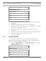
Preset Setup
The camera has a maximum of 210 programmable preset
positions. Each of the user-defined presets includes Pan/Tilt/
Zoom. To set up (program) a preset:
4
From the MAIN MENU, select PRESET SETUP. The screen
PRESET SETUP appears.
PRESET SETUP
NO.
EDIT
2013.04 | |
Bosch Security Systems, Inc.
AUTODOME 4000 Mini
PTZ Dome
On-Screen Display (OSD) Menu | en
69
PRESET SETUP
TITLE
D TIME
CLEAR
SAVE
BACK
1.
Select the option "NO.###" to select a preset number.
2.
Select the appropriate preset number.
3.
Select the option "Edit." A second screen PRESET SETUP
appears.
4.
Using the joystick, move to a desired target (Pan/Tilt/
Zoom).
5.
Save the settings.
6.
Return to the previous screen.
7.
Select the option "D Time" to set the dwell time for the
preset.
8.
Set the desired dwell time (from 3 to 60 seconds).
9.
Save the settings.
Note: Select the option "Clear" to delete the preset.
Notice!
You can also edit the Preset title. Select the option "Title," then
edit the title following the steps in Editing Titles, page 43.
Bosch Security Systems, Inc.
2013.04 | |
70
en | On-Screen Display (OSD) Menu
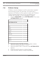
7.8
Pattern Setup
AUTODOME 4000 Mini
PTZ Dome
A Pattern is used to display (or recall) a memorized, repeated
and serial trace of pan, tilt, and zoom. The camera has a
maximum of 8 Patterns in Pelco protocol mode, and 2 Patterns
in Bosch protocol mode. Each of the user-defined scans
includes Pan/Tilt/Zoom. To set up (program) a Pattern:
4
From the MAIN MENU, select PATTERN SETUP. The screen
PATTERN SETUP appears.
PATTERN SETUP
NO.
EDIT
TITLE
TIME
CLEAR
SAVE
BACK
1.
Select the option "NO.###" to select a pattern number.
2.
Select the appropriate pattern number.
3.
Select the option "Edit." A second screen PATTERN SETUP
appears.
2013.04 | |
4.
Using the joystick, move to a desired target.
5.
Press the button [Near] to begin programming.
Bosch Security Systems, Inc.
AUTODOME 4000 Mini
PTZ Dome
6.
On-Screen Display (OSD) Menu | en
71
Using the joystick, record the scene. Note that ’Time’
means recorded time. The maximum amount of time
available for recording is 60 seconds.
7.
Save the settings.
Note: Select the option "Clear" to delete the pattern.
Notice!
You can also edit the Pattern title. Select the option "Title,"
then edit the title following the steps in Editing Titles, page 43.
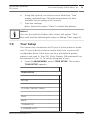
7.9
Tour Setup
The camera has a maximum of 8 Tours in Pelco protocol mode,
and 2 Tours in Bosch protocol mode. Each tour can have 28
configurable items. Each item can be a pre-defined preset,
pattern, and scan in Tour 2-8. (Only Presets (28 maximum) can
be inserted in Tour 1.) To set up (program) a tour:
4
From the MAIN MENU, select TOUR SETUP. The screen
TOUR SETUP appears.
TOUR SETUP
NO.###
(-TOUR1: PRESET ONLY)
SAVE
BACK
- CHANGE ID
(- CHANGE ACT)
Bosch Security Systems, Inc.
2013.04 | |
72
en | On-Screen Display (OSD) Menu
AUTODOME 4000 Mini
PTZ Dome
TOUR SETUP
(- CLEAR ID)
1.
Select a tour number.
2.
Select the first item in the list. From here you can:
–
Press the button [Tele/Wide] to select a Preset, a
Pattern, a Tour, and/or a Scan in each item.
–
Press the button[Tele/Wide] to change the number of
the action.
–
Press the button [Near/Far] to change the mode of the
action.
–
Press the button [Near/Far] to clear (delete) the action
in each item.
3.
Repeat steps 2 and 3 for additional tours.
4.
Save the settings.
Note: Select the option "Clear" to delete the tour.
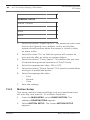
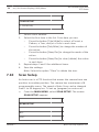
7.10
Scan Setup
An Auto scan is a PTZ function that moves the camera from one
position to another position. The camera has a maximum of 8
programmable scans. The speed of Auto Scan can be changed
from 1 to 35 degree/sec. To set up (program) an auto scan:
4
From the MAIN MENU, select SCAN SETUP. The screen
SCAN SETUP appears.
SCAN SETUP
NO.
EDIT
2013.04 | |
Bosch Security Systems, Inc.
AUTODOME 4000 Mini
PTZ Dome
On-Screen Display (OSD) Menu | en
73
SCAN SETUP
SPEED
DTIME
DIRECTION
MODE
CLEAR
SAVE
BACK
1.
Select the option "NO.###" to select a scan number.
2.
Select the appropriate scan number.
3.
Select the option "Edit."
4.
Select the value "Edit Start Point." The screen Start
Position Setup appears.
5.
Using the joystick, move to a desired target (Pan/Tilt/Zoom)
for the starting point of the scan.
6.
7.
Save the settings. The screen Stop Position Setup appears.
Using the joystick, move to a desired target (Pan/Tilt/Zoom)
for the stopping point of the scan.
8.
Save the settings.
9.
Return to the previous screen.
10. Select the option "Speed."
11. Select the desired speed (from 1° to 35°/second).
12. Select the option "DTime" to set the dwell time for the
scan.
13. Set the desired time (from 3 minute to 60 seconds).
14. Select the option "Direction."
15. Select the appropriate value for the direction of the scan.
Bosch Security Systems, Inc.
2013.04 | |
74
en | On-Screen Display (OSD) Menu
AUTODOME 4000 Mini
PTZ Dome
16. Select the option "Mode."
17. Select the appropriate value for the mode. In Auto Scan
there are two modes:
–
Endless mode: When the Start Position is the same as
the Stop Position, the dome moves around.
–
Coming/Going mode: When the Start Position is
different from the Stop Position, the dome moves
repeatedly from one position to another.
18. Save the settings.
Note: Select the option "Clear" to delete the scan.
Notice!
In order to call an action (Preset, Pattern, Tour, or Scan), you
must save Preset, Pattern, Tour, or Scan first.
You can also edit the Scan title. Select the option "Title," then
edit the title following the steps in Editing Titles, page 43.
7.11
Alarm Setup
This menu controls alarm inputs and outputs. To set alarms:
1.
From the MAIN MENU, select ALARM SETUP. The screen
ALARM SETUP appears.
2.
Select the option "NO.###" to select a preset number.
ALARM SETUP
NO.
IN
OUT
PRIORITY
ACTION
2013.04 | |
Bosch Security Systems, Inc.
AUTODOME 4000 Mini
PTZ Dome
On-Screen Display (OSD) Menu | en
75
ALARM SETUP
NUMBER
ATIME
SAVE
BACK
- SET/CLEAR
1.
Select the appropriate alarm number.
2.
Select the option "In" to select the alarm input type.
3.
Select the appropriate value: N.O. (Normally Open) or N.C.
(Normally Closed).
4.
Select the option "Out" to select the alarm output.
5.
Select the appropriate value: ON or OFF.
6.
Select the option "Priority."
7.
Select the appropriate priority from 1-4.
8.
Select the option "Action."
9.
Select the appropriate action: Off, Preset, Pattern, Scan, or
Tour.
10. Select the option "Number."
11. Select the number of the action (Preset, Pattern, Scan, or
Tour).
12. Select the option "ATime" to set the alarm time for the
action.
13. Set the desired dwell time:
–
Time Out (3-60seconds). This is activated during a
–
Momentary (On): When an alarm is triggered, the
selected dwell time when an alarm is triggered.
camera will maintain alarm activation continuously,
until it is stopped manually (96+preset in Pelco
protocol; [Off]+[65]+[Enter] in Bosch protocol).
14. Save the settings.
Note: Select the option "Clear" to delete the alarm.
Bosch Security Systems, Inc.
2013.04 | |
76
en | On-Screen Display (OSD) Menu
AUTODOME 4000 Mini
PTZ Dome
Notice!
In order to call an action (Preset, Pattern, Tour, or Scan), you
must save Preset, Pattern, Tour, or Scan first.
2013.04 | |
Bosch Security Systems, Inc.
AUTODOME 4000 Mini
PTZ Dome
8
Troubleshooting | en
77
Troubleshooting
If problems occur, check the installation of the camera with the
instructions in this manual. Refer to this guide for further
information.
Problem
Solution
No video on screen.
- Verify that the power is connected
to all components in the system.
- Verify that the power switch is
ON.
- Verify the status of cables or the
connection of cables.
Poor video quality.
- Check the power supply voltage
(normal 24 VAC) directly at the
camera.
- Check the camera settings.
- Check the video quality directly at
the camera with a service monitor.
- Check the quality and length of
video cables, and possible EMC
interference.
- Check the quality of connectors
and potential moisture/corrosion.
- If the lens or the dome window is
dirty, clean it with a clean cloth.
Bosch Security Systems, Inc.
2013.04 | |
78
AUTODOME 4000 Mini
PTZ Dome
en | Troubleshooting
Problem
Solution
Camera is not working
- Power-cycle the camera and
properly (including
power supply, or reset the camera
wrong position of
using the configuration menu [Main
camera).
> System > Reboot].
- Check the connection of the
power cable and the status of the
camera.
- Initialize the camera [Main >
System > Initialize].
- Check the power rating of the
power supply.
- Measure the voltage at the camera
(since there could be a drop in
voltage due cable length). The
power consumption increases
when the camera is moving
(especially at high speed) and
when the heater is on. The voltage
at the camera should always be
24VAC (+/- 10%).
The communication
- Check that the RS-485 cable is
between controller and
connected correctly.
camera (via RS-485
- Check the ID/Protocol/Baud rate/
cable) is not working
Termination setting.
properly.
2013.04 | |
Bosch Security Systems, Inc.
AUTODOME 4000 Mini
PTZ Dome
Problem
Troubleshooting | en
79
Solution
The surface of the dome - Check the voltage level of the
case is hot.
dome camera and the status of the
camera.
- Check that the camera is
connected to the proper power.
The image on the screen - Check to see if the camera faces
flickers.
directly into the sun or a
fluorescent lamp. If so, reposition
the dome. - Check for flickers on
the screen.
Bosch Security Systems, Inc.
2013.04 | |
80
AUTODOME 4000 Mini
PTZ Dome
en | Technical Specifications
9
Technical Specifications
Camera Module
Imager
1/4" Double Scan, Super HAD
CCD
Effective Pixels
NTSC: 976(H)*494(V), PAL:
976(H)*582(V)
Resolution
600 TVL
Zoom ratio
26X Effective Optical Zoom/10X
Digital Zoom (Auto Focus)
Lens
fW=3.49 ±0.17mm fT=104.02
±5.20mm (30X +/- 10% Optical
Zoom)
View Angle (Approximate)
69.5° to 2.46°
Day/Night
Mechanical Day/Night filter
Minimum Illumination
0.2 Lux/ F1.65, 0.001 Lux/DSS,
0.1 Lux/ICR
Signal-to-Noise Ratio
>50 dB
(SNR)
Wide Dynamic Range
On/Off
(WDR)
Dynamic Noise Reduction
3 DNR
(DNR)
Privacy Masking
15 zones maximum
Maximum Preset Speed
360°/sec
Flip
Rotate 180° at bottom of tilt
Auto Scan
2/8 Auto Scan modes including
vector scan
2013.04 | |
Bosch Security Systems, Inc.
AUTODOME 4000 Mini
PTZ Dome
Technical Specifications | en
81
Camera Module
Preset Position
99/210 Positions with camera
status
Tour
2/8 Tours (Preset, Pattern, Scan)
Pattern
2/8 Patterns
On-screen Display (OSD)
Display camera ID, Title, Mode,
and Angle on-screen(MultiLanguage)
Multi-language OSD
English, Chinese, Dutch, German,
French, Italian, Russian, Spanish
Electrical
Power Supply
24 VAC (±10%) Normal, Built-in
Power Line Surge
Power Requirements
Adaptor 24VAC, 1A (2.5A with
heater)
Power Consumption
24 VAC, 850mA / 20W (without
heater)24 VAC, 2A / 45W (with
heater)
Alarm Input
4 Normal Dry Contact (Selectable
NC/NO)
Alarm Output
1 Normal Relays 5VDC/40mA Max
(Selectable NC/NO)
Control
RS-485 baud rate:
2400~38.4Kbps (default:
9600bps)
Access Time
0.75 second maximum preset
recall time
Camera Address / ID
Bosch Security Systems, Inc.
Physical 99
2013.04 | |
82
AUTODOME 4000 Mini
PTZ Dome
en | Technical Specifications
Camera Module
Mechanical
Weight
1.5 kg
Dimension
Ø154 x 138 mm (H) (Bubble
Dome Ø110)
Pan Angle
360° Continuous rotation
Environment
Operating Temperature
-10 °C to +50 °C (14 °F to +122
°F)
(heater off)
-40 °C to +10 °C (-40 °F to 50 °F)
(heater on)
Heater (Built-in)
On/Off: 0 °C to 10 °C
Operating Humidity
~80% relative humidity (RH)
Storage Temperature
-20 °C to +60 °C (-4 °F to +140
°F)
2013.04 | |
Bosch Security Systems, Inc.
AUTODOME 4000 Mini
PTZ Dome
10
Dimensions | en
83
Dimensions
79
(3.11)
26
(1.02)
138
(5.43)
Ø112
(4.41)
Ø151.3
(5.96)
mm
(in.)
Ø154
(6.06)
Figure 10.1: Dimensions - Camera
85.6
(3.37)
4-Ø4.8
(0.19)
mm
(in.)
85.6
(3.37)
Figure 10.2: Dimensions - Mounting Holes
Bosch Security Systems, Inc.
2013.04 | |
84
AUTODOME 4000 Mini
PTZ Dome
en | Bosch Protocol
11
Bosch Protocol
The following table lists camera functions in Bosch protocol.
Preset
Key
Preset
Example
Number
Function
Activate Command
Example
/
Deactiv
ate
Auto Scan 1
On/Off
Scan 1
ON
+1+Enter
Auto Scan 2
On/Off
Scan 2
ON
+2+Enter
Pre-Position Tour
On/Off
Tour 1
ON
+8+Enter
Group Tour
On/Off
Tour 2
ON
+9+Enter
Backlight
On/Off
Backlight Comp.
Compensation
Enters White
+20+Enter
On/Off
WB Setup
ON
Balance menu
Restores Camera
+35+Enter
On
Settings
Enters Main
On
Camera Default
ON
Restored
+40+Enter
Main Menu
ON
Setup Menu
Playback A
+46+Enter
On/Off
Pattern 1
(Continuous)
Playback A
(Single)
2013.04 | |
ON
ON
+50+Enter
On/Off
Pattern 1
ON
+51+Enter
Bosch Security Systems, Inc.
AUTODOME 4000 Mini
PTZ Dome
Preset
Bosch Protocol | en
Key
Preset
85
Example
Number
Playback B
On/Off
Pattern 2
(Continuous)
Playback B
+52+Enter
On/Off
Pattern 2
(Single)
Enters Alarm
ON
+53+Enter
On
Alarm Menu
Menu
Acknowledge
ON
ON
+64+Enter
Off
Alarms and
Alarm Action
Off
stopped
+65+Enter
*SW Ver. Displayed
ON
Deactivate Alarms
Displays SW
On
version no.
Changes to
+66+Enter
On/Off
*Digital Zoom
Digital Zoom
ON
+80+Enter
mode
Enters Privacy
On/Off
Privacy Masking
Masking menu
Record A: Enters
ON
+87+Enter
On/Off
Pattern 1
Pattern Setup
ON
+100+Enter
menu
Record B: Enters
On/Off
Pattern 2
Pattern setup
ON
+101+Enter
menu
Pre-Position
Set
Preset 1-99
Programming
Pre-Position
Recall
Bosch Security Systems, Inc.
Set
+99+Enter
Shot
Preset 1-99
Shot
+99+Enter
2013.04 | |
86
AUTODOME 4000 Mini
PTZ Dome
en | Bosch Protocol
Preset
Key
Preset
Example
Number
Set-recalibrate
Set
Run Calibration
Home Position
Restores all
Set
+110+Enter
Factory Reset
settings
Set
+899+Enter
* SW Version Number displays 5seconds.
*OSD message “D.ZOOM” in D.Z range displays 2 seconds.
2013.04 | |
Bosch Security Systems, Inc.
AUTODOME 4000 Mini
PTZ Dome
12
Pelco Protocol | en
87
Pelco Protocol
The following table lists camera functions in Pelco protocol.
Preset
Key
Preset
Operation Example
Numbe
r
Preset
Preset
1-59,
No.
101-25
+Preset
1+Preset
0
Preset
* Preset
1-59,
shortcut
101-25
saving
0
Run PAN
Preset
Run PAN ZERO Preset
Scan Setup
Scan
Preset
Preset/Scan
33
34
60
61-68
*
*
No.
33+Prese
+Preset
t
No.
34+Prese
+Preset
t
No.
60+Prese
+Preset
t
No.
61+Prese
+Preset
t
1+Scan
Tour Setup
Tour
Preset
Preset/Tour
70
71-78
No.
70+Prese
+Preset
t
No.
71+Prese
+Preset
t
1+Tour
Pattern Setup
Bosch Security Systems, Inc.
Preset
80
No.
80+Prese
+Preset
t
2013.04 | |
88
AUTODOME 4000 Mini
PTZ Dome
en | Pelco Protocol
Preset
Key
Preset
Operation Example
Numbe
r
Pattern
Preset/
81-88
Pattern
No.
81+Prese
+Preset
t
1+Patter
n
ENT Key
Run HOME
CLR Key
ENT2 Key
MENU Key
Preset
Preset
Preset
Preset
Preset/
90
91
92
94
95
**Menu
ESC Key
D.Zoom
(Toggle)
Preset
Preset
96
97
No.
90+Prese
+Preset
t
No.
91+Prese
+Preset
t
No.
92+Prese
+Preset
t
No.
94+Prese
+Preset
t
No.
95+Prese
+Preset
t
No.
96+Prese
+Preset
t
No.
97+Prese
+Preset
t
Notice!
#
- To save position of the dome, press the desired preset
number and hold the [PRESET] key for 2 seconds.- To go to the
MAIN MENU, press and hold the [MENU] key for 2 seconds.
2013.04 | |
Bosch Security Systems, Inc.
Bosch Security Systems, Inc.
850 Greenfield Road
Lancaster, PA, 17601
USA
www.boschsecurity.com
© Bosch Security Systems, Inc., 2014
Bosch Sicherheitssysteme GmbH
Robert-Bosch-Ring 5
85630 Grasbrunn
Germany