1
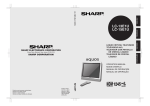
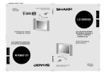
15M4UCover 01.07.24
ENGLISH
LC-15M4U
Impreso en papel reciclado.
Impresso em papel reciclado pós utilização.
Impreso en Japón
Impresso no Japão
TINS-7526CEZZ
FRANÇAIS
LC-15M4U
MANUAL DE MANEJO
MANUAL DE OPERAÇÃO
LCD AV MONITOR
MONITEUR AV À CRISTAUX
LIQUIDES
MONITOR AV LCD
MONITOR AV DE TELA
DE CRISTAL LÍQUIDO
OPERATION MANUAL
MODE D’EMPLOI
LC-15M4U
PORTUGUÊS
ESPAÑOL
Printed on post-consumer recycled paper.
Imprimé sur du papier recyclé.
Printed in Japan
Imprimé au Japon
TINS-7526CEZZ
ENGLISH
LC-15M4U
LCD AV MONITOR
ENGLISH
OPERATION MANUAL
LC-15M4U(01-08)Eng.p65
1
01.7.24, 5:21 PM
IMPORTANT INFORMATION
WARNING:
TO REDUCE THE RISK OF FIRE OR ELECTRIC SHOCK, DO
NOT EXPOSE THIS PRODUCT TO RAIN OR MOISTURE.
CAUTION
RISK OF ELECTRIC SHOCK.
DO NOT OPEN.
CAUTION: TO REDUCE THE RISK OF ELECTRIC SHOCK,
DO NOT REMOVE COVER (OR BACK).
NO USER-SERVICEABLE PARTS INSIDE.
REFER SERVICING TO QUALIFIED SERVICE
PERSONNEL.
The lightning flash with arrowhead symbol, within an equilateral triangle, is intended to alert
the user to the presence of
uninsulated “dangerous voltage”
within the product’s enclosure
that may be of sufficient
magnitude to constitute a risk of
electric shock to persons.
The exclamation point within a
triangle is intended to alert the
user to the presence of important operating and maintenance
(servicing) instructions in the
literature accompanying the
product.
Declaration of Conformity
SHARP LCD AV MONITOR MODEL LC-15M4U
This device complies with part 15 of the FCC rules. Operation is subject to the following conditions: (1) This
device may not cause harmful interference, and (2) this device must accept any interference received,
including interference that may cause undesired operation.
Responsible Party:
SHARP ELECTRONICS CORPORATION
Sharp Plaza, Mahwah, New Jersey 07430
TEL : 1-800-BE-SHARP (1-800-237-4277)
U.S.A. ONLY
WARNING: FCC Regulations state that any unauthorized changes or modifications to this equipment
not expressly approved by the manufacturer could void the user’s authority to operate this equipment.
U.S.A. ONLY
CAUTION: Use the supplied AC cord as it is.
Do not remove the core part from the AC cord, and do not
change the way of winding cables around the core part.
INFORMATION
This equipment has been tested and found to comply with the limits for a Class B digital device, pursuant to
Part 15 of the FCC Rules. These limits are designed to provide reasonable protection against harmful
interference in a residential installation. This equipment generates, uses, and can radiate radio frequency
energy and, if not installed and used in accordance with instructions, may cause harmful interference to
radio communications. However, there is no guarantee that interference will not occur in a particular
installation. If this equipment does cause harmful interference to radio or television reception, which can be
determined by turning the equipment off and on, the user is encouraged to try to correct the interference by
one or more of the following measures:
• Relocate or adjust the receiving antenna.
• Increase the separation between the equipment and receiver.
• Connect the equipment into an outlet on a circuit different from that to which the receiver is connected.
• Consult the dealer or an experienced radio/TV technician for help.
U.S.A. ONLY
2
LC-15M4U(01-08)Eng.p65
2
01.7.24, 5:21 PM
IMPORTANT INFORMATION (Continued)
CAUTION: TO PREVENT ELECTRIC SHOCK, MATCH WIDE BLADE OF
PLUG TO WIDE SLOT, FULLY INSERT.
This product utilizes tin-lead solder, and fluorescent lamp containing a small amount of mercury.
Disposal of these materials may be regulated due to environmental considerations. For disposal or
recycling information, please contact your local authorities or the Electronic Industries Alliance:
www.eia.org
3
LC-15M4U(01-08)Eng.p65
3
01.7.24, 5:21 PM
DEAR SHARP CUSTOMER
Thank you for your purchase of the Sharp LCD product. To ensure safety and many
years of trouble-free operation of your product, please read the Safety Precautions
carefully before using this product.
IMPORTANT SAFETY PRECAUTIONS
Electricity is used to perform many useful functions, but it can also cause personal injuries and property
damage if improperly handled. This product has been engineered and manufactured with the highest
priority on safety. However, improper use can result in electric shock and/or fire. In order to prevent
potential danger, please observe the following instructions when installing, operating and cleaning the
product. To ensure your safety and prolong the service life of your LCD product, please read the following
precautions carefully before using the product.
1. Read instructions—All operating instructions must be read and understood before the product is
operated.
2. Keep this manual in a safe place—These safety and operating instructions must be kept in a safe
place for future reference.
3. Observe warnings—All warnings on the product and in the instructions must be observed closely.
4. Follow instructions—All operating instructions must be followed.
5. Cleaning—Unplug the power cord from the AC outlet before cleaning the product. Use a damp
cloth to clean the product. Do not use liquid cleaners or aerosol cleaners.
6. Attachments—Do not use attachments not recommended by the manufacturer. Use of inadequate
attachments can result in accidents.
7. Water and moisture—Do not use the product near water, such as bathtub, washbasin, kitchen
sink and laundry tub, swimming pool and in a wet basement.
8. Stand—Do not place the product on an unstable cart, stand, tripod or table. Placing the product
on an unstable base can cause the product to fall, resulting in serious personal injuries as well as
damage to the product. Use only a cart, stand, tripod, bracket or table recommended by the
manufacturer or sold with the product. When mounting the product on a wall, be sure to follow the
manufacturer’s instructions. Use only the mounting hardware recommended by the manufacturer.
9. When relocating the product placed on a cart, it must be moved with utmost care.
Sudden stops, excessive force and uneven floor surface can cause the product to
fall from the cart.
10. Ventilation—The vents and other openings in the cabinet are designed for
ventilation. Do not cover or block these vents and openings since insufficient
ventilation can cause overheating and/or shorten the life of the product. Do not
place the product on a bed, sofa, rug or other similar surface, since they can
block ventilation openings. This product is not designed for built-in installation; do
not place the product in an enclosed place such as a bookcase or rack, unless
proper ventilation is provided or the manufacturer’s instructions are followed.
11. Power source—This product must operate on a power source specified on the specification label.
If you are not sure of the type of power supply used in your home, consult your dealer or local
power company. For units designed to operate on batteries or another power source, refer to the
operating instructions.
12. Power cord protection—The power cords must be routed properly to prevent people from stepping
on them or objects from resting on them. Check the cords at the plugs and product.
13. If the AC adapter is misplaced or needs to be replaced, obtain the same type of adapter from a
SHARP service center or your dealer.
14. If you plan to use a 12-VDC power supply unit other than the AC adapter supplied with the
product, make sure the power supply unit provides stable voltage with minimum fluctuations.
Unstable power supply can cause problems in the product.
15. The LCD panel used in this product is made of glass. Therefore, it can break when the product is
dropped or applied with impact. Be careful not to be injured by broken glass pieces in case the
LCD panel breaks.
16. Overloading—Do not overload AC outlets or extension cords. Overloading can cause fire or
electric shock.
17. Entering of objects and liquids—Never insert an object into the product through vents or openings.
High voltage flows in the product, and inserting an object can cause electric shock and/or short
internal parts. For the same reason, do not spill water or liquid on the product.
4
LC-15M4U(01-08)Eng.p65
4
01.7.24, 5:21 PM
18. Servicing—Do not attempt to service the product yourself. Removing covers can expose you to
high voltage and other dangerous conditions. Request a qualified service person to perform
servicing.
19. Repair—If any of the following conditions occurs, unplug the power cord from the AC outlet, and
request a qualified service person to perform repairs.
a.When the power cord or plug is damaged.
b.When a liquid was spilled on the product or when objects have fallen into the product.
c. When the product has been exposed to rain or water.
d.When the product does not operate properly as described in the operating instructions.
Do not touch the controls other than those described in the operating instructions. Improper
adjustment of controls not described in the instructions can cause damage, which often requires
extensive adjustment work by a qualified technician.
e.When the product has been dropped or damaged.
f. When the product displays an abnormal condition. Any noticeable abnormality in the product
indicates that the product needs servicing.
20. Replacement parts—In case the product needs replacement parts, make sure that the service
person uses replacement parts specified by the manufacturer, or those with the same characteristics and performance as the original parts. Use of unauthorized parts can result in fire, electric
shock and/or other danger.
21. Safety checks—Upon completion of service or repair work, request the service technician to
perform safety checks to ensure that the product is in proper operating condition.
22. Wall or ceiling mounting—When mounting the product on a wall or ceiling, be sure to install the
product according to the method recommended by the manufacturer.
23. Heat sources—Keep the product away from heat sources such as radiators, heaters, stoves and
other heat-generating products (including amplifiers).
24. Polarization—This AC adapter may be equipped with a polarized alternating current line plug (a
plug having one blade wider than the other). This plug will fit into the power outlet only one way.
This is a safety feature. If you are unable to insert the plug fully into the outlet, try reversing the
plug. If the plug should still fail to fit, contact your electrician to replace your obsolete outlet.
Do not defeat the safety purpose of the polarized plug.
The LCD panel is a very high technology product with 921,600 thin film transistors, giving you fine
picture details.
Occasionally, a few non-active pixels may appear on the screen as a fixed point of blue, green or
red.
Please note that this does not affect the performance of your product.
5
LC-15M4U(01-08)Eng.p65
5
01.7.24, 5:21 PM
CONTENTS
Page
DEAR SHARP CUSTOMER ............................................................................................................. 4
IMPORTANT SAFETY PRECAUTIONS .......................................................................................... 4
SUPPLIED ACCESSORIES ............................................................................................................. 7
PREPARATION ................................................................................................................................. 8
Power Connection ...................................................................................................................... 8
Batteries for Remote Control .................................................................................................... 8
NAMES OF PARTS (Main Unit) ...................................................................................................... 9
Names of Parts (Remote Control) .......................................................................................... 11
BASIC OPERATION ....................................................................................................................... 12
Turning on MAIN POWER ........................................................................................................ 12
Switching the AV INPUT [AV1/AV2] Mode ............................................................................. 12
Sound Volume ........................................................................................................................... 13
ON/OFF Standby ....................................................................................................................... 13
SELECTING THE MENU ITEMS .................................................................................................... 14
ADJUSTMENT ................................................................................................................................ 15
Adjusting the LANGUAGE Settings ........................................................................................ 15
Adjusting the PICTURE Settings ............................................................................................ 16
Adjusting the SET UP Settings ............................................................................................... 18
Adjusting the SLEEP TIMER Settings .................................................................................... 19
CONNECTING TO EXTERNAL DEVICES ..................................................................................... 20
Connecting to a VCR, a DVD player etc. (AV 1/2 IN) ............................................................ 20
Connecting to a DVD player (COMPONENT terminal) ......................................................... 21
Outputting video and audio (video output) ........................................................................... 22
Listening with Headphones ..................................................................................................... 22
Watching TV .............................................................................................................................. 23
EXAMPLE OF APPLICATION ....................................................................................................... 24
Mounting the LCD monitor on a wall ..................................................................................... 24
TROUBLESHOOTING .................................................................................................................... 25
SPECIFICATIONS ........................................................................................................................... 26
DIMENSIONAL DRAWINGS .......................................................................................................... 27
6
LC-15M4U(01-08)Eng.p65
6
01.7.24, 5:21 PM
SUPPLIED ACCESSORIES
Make sure the following accessories are provided with the product.
Wireless Remote Control (×1)
LC-15M4U
FRANÇAIS
ENGLISH
Operation Manual (×1)
LCD AV MONITOR
MONITEUR AV Á CRISTAUX
LIQUIDES
OPERATION MANUAL
MODE D’EMPLOI
Printed in Japan
Imprimé au Japon
TINS-7526CEZZ
Printed on post-consumer recycled paper.
Imprimé sur du papier recyclé.
TINS-7526CEZZ
RRMCG1459CESA
AC Adapter (×1)
AC Cord (×1)
QACCD3097CEPZ
UADP-0228CEPZ
“AAA” size (UM/SUM-4)
Wall Mount Bracket (×1)
Dry Battery (×2)
UBATU0026GEZZ
* Product shape varies in some countries
Wall Mount Anchor
and Screw (×4)
Fixed Screw
for Set Stand (×1)
LANGU9041CESA
7
LC-15M4U(01-08)Eng.p65
7
01.7.24, 5:21 PM
PREPARATION
Power Connection
Connect to DC input
terminal of the product.
Plug into AC outlet.
Household power outlet
DC input terminal
(12 VDC)
AC cord
AC adapter
Notes:
■ Always turn the main power switch of the LCD monitor to OFF when connecting the AC adapter.
■ Always unplug the AC adapter from the product and power outlet when not being used for a long period of time.
Batteries for Remote Control
If the remote control fails to operate monitor functions, replace the batteries in the remote control.
1
2
Open the battery
cover.
■ Slide the cover while
pressing down.
Insert batteries (two “AAA”
size (UM/SUM-4) batteries,
supplied with product).
3
Close the battery
cover.
■ Place batteries with their
terminals corresponding to
the (+) and (–) indications
in the battery compartment.
Caution!
Cautions regarding batteries
Improper use of batteries can result in a leakage of chemicals and/or explosion. Be sure to follow the
instructions below.
• Place batteries with their terminals corresponding to the (+) and (–) indications.
• Different types of batteries have different characteristics. Do not mix batteries of different types.
• Do not mix old and new batteries. Mixing old and new batteries can shorten the life of new batteries
and/or cause old batteries to leak chemicals.
• Remove batteries as soon as they are non-operable.
Chemicals that leak from batteries can cause a rash. If chemical leakage is found, wipe with a cloth.
• The batteries supplied with the product may have a shorter life expectancy due to storage conditions.
• If the remote control is not used for an extended period of time, remove batteries from the remote
control.
8
LC-15M4U(01-08)Eng.p65
8
01.7.24, 5:21 PM
NAMES OF PARTS (Main Unit)
Main unit (front view)
Remote sensor
window
Power/Standby
indicator
Speakers
Side control section
MAIN POWER switch
MAIN
POWER
ON
OFF
AV INPUT
AV INPUT button
+
VOL
SELECT
VOL (+)/(–) buttons
SELECT (])/([)
buttons
MENU
MENU button
The six buttons shown at the left
have the same functions as
those on the remote control.
* When this manual describes
button functions, it is referring
to the buttons on the remote
control.
9
LC-15M4U(09-14)Eng.p65
9
01.7.24, 5:20 PM
NAMES OF PARTS (Main Unit) (Continued)
Main unit (rear view)
Stand
Rear Speaker
(woofer)
Rear terminal section
Can also be used as video
output terminals.
AV 2 IN/OUT
AUDIO
R
AV 1 IN
VIDEO
L
AUDIO
R
VIDEO
COMPONENT
L
Y
PB
PR
AUDIO
AUDIO
POWER INPUT
DC12V
VIDEO
VIDEO
POWER
INPUT
HEAD DC12V
PHONE
COMPONENT
HEADPHONE
AV 2 IN/OUT
AV 1 IN
10
LC-15M4U(09-14)Eng.p65
10
01.7.24, 5:20 PM
NAMES OF PARTS (Remote Control)
Remote control
Infrared transmitter window
Menu control section
ON/OFF
Power ON/OFF
button
MUTE
Sound MUTE button
MENU
AV INPUT
AV INPUT
button
MENU button
SELECT
VOL
SELECT (])/([) buttons
VOL
VOL (+)/(–) buttons
SELECT
LCD MONITOR
■ The side control section of the main unit is also provided with the AV INPUT, SELECT (])/([),
VOL (+)/(–) and MENU buttons.
* When this manual describes button functions, it is referring to the buttons on the remote control.
Side control section of main unit
The main power
switch is not
provided on the
remote control.
MENU
AV INPUT
MAIN
POWER
ON
ON/OFF
AV INPUT
MENU
AV INPUT
SELECT
SELECT
VOL
MUTE
OFF
VOL
+
VOL
VOL
VOL
SELECT
SELECT
ON/OFF
MUTE
SELECT
MENU
AV INPUT
MENU
SELECT
VOL
VOL
11
LC-15M4U(09-14)Eng.p65
11
01.7.24, 5:20 PM
BASIC OPERATION
Turning on MAIN POWER
Control section of main unit
MAIN
POWER
ON
OFF
1
Slide MAIN POWER, located on the
right side of the main unit, to ON.
2
The power indicator instantaneously
changes from red to green and the
main unit is turned on.
▼ On-screen display
AV1
N358
Notes:
■ When the Power indicator is red, press
ON/OFF on the remote control to turn on
the monitor.
The Power indicator changes from red to
green.
■ The input mode indication disappears after
five seconds.
Power/Standby indicator
Switching the AV INPUT [AV1/AV2] Mode
ON/OFF
MUTE
ON/OFF
AV INPUT
MENU
AV INPUT
SELECT
VOL
VOL
SELECT
1
Turn on the power of the connected
video equipment.
2
Press AV INPUT and select the
applicable input source. The screen
displays AV1 or AV2 mode at the
upper right corner each time AV
INPUT is pressed.
Note:
■ The AV input mode indication remains for
five seconds.
• AV1: Video equipment connected to the
AV1 input terminals.
The display of the AV1 mode indicates
either AV1 or COMPONENT depending on the adjustment of the SET UP
settings.
AV1 is displayed when AV1 is set to
NORMAL in the SET UP settings, and
COMPONENT is displayed when AV1
is set to COMPONENT.
(see page 18)
LCD MONITOR
Initial mode (AV1)
AV1 mode
AV1
AV2 mode
• AV2: The AV2 mode can be set to either IN
or OUT in the SET UP settings.
(see page 18)
AV2 indication is not displayed when
the mode is selected to OUT.
12
LC-15M4U(09-14)Eng.p65
12
01.7.24, 5:20 PM
AV2
BASIC OPERATION (Continued)
Sound Volume
To adjust the volume
ON/OFF
MUTE
MUTE
MENU
AV INPUT
SELECT
VOL
| Press VOL (+) to increase the sound
volume. The indicator segment
increases.
VOLUME
50
| Press VOL (–) to decrease the sound
volume. The indicator segment
decreases.
VOLUME
10
VOL
SELECT
VOL
(+)/( )
LCD MONITOR
To mute the sound
| Press MUTE to temporarily turn off the
sound.
is displayed.
The MUTE mark
| Press MUTE or VOL (+)/(–) to turn the
sound back to the previous level.
disappears.
The MUTE mark
Note:
■ MUTE is automatically cleared when the
following button is pressed: ON/OFF,
VOL (+)/(–) or MUTE.
VOLUME
30
ON/OFF Standby
ON/OFF
ON/OFF
MUTE
Press ON/OFF.
The power indicator turns red.
MENU
AV INPUT
To turn off the LCD monitor
SELECT
To turn the LCD monitor back on
VOL
VOL
Press ON/OFF again.
The power indicator turns green.
SELECT
LCD MONITOR
13
LC-15M4U(09-14)Eng.p65
13
01.7.24, 5:20 PM
SELECTING THE MENU ITEMS
Selecting the Menu Items
• This LCD monitor set allows you to adjust the picture, sound, and other features using the On-screen
Display. Select the desired menu item by following the steps below and then refer to the indicated page
for details.
ON/OFF
MUTE
VOL
(+)/( )
MENU
AV INPUT
Press MENU to display the MENU
screen.
2
Press SELECT (])/([) to select
the desired menu item.
MENU
SELECT
VOL
1
SELECT
(])/([)
PICTURE(AV1)
CONTRAST
TINT
COLOR
BLACK LEVEL
SHARPNESS
RED-BLUE
GREEN
COLOR SYSTEM
RESET
• The cursor moves up or down.
• The cursor indicates the selected
menu item.
VOL
SELECT
(Pages 16 and 17)
3
4
Press VOL (+)/(–) to enter.
SELECT:
Press MENU again to exit.
SET UP
BRIGHTNESS
UPSIDE
RIGHT/LEFT
BLUE SCREEN
AV1
AV2 IN/OUT
SLEEP TIMER
SELECT:
SELECT:
ENTER: –VOL+
EXIT: MENU
[BRIGHT ]
[NORMAL]
[NORMAL]
[OFF
]
[NORMAL]
[IN
]
[ – – – REMAIN]
ADJUST: –VOL+ EXIT: MENU
LANGUAGE
ENGLISH
ESPAÑOL
FRANÇAIS
SELECT:
* The screen indications shown above are larger than actual size for easy reading.
14
14
EXIT: MENU
(Page 15)
Notes:
■ The displayed items differ depending
on the setting conditions.
■ The selected item is highlighted in
yellow.
■ Items in purple cannot be selected.
■ The original screen is restored by
pressing MENU on the menu screen
or any of the adjustment screens.
The original screen is also restored
when no buttons have been pressed
for about a period of 30 seconds.
The adjustment values and settings
that were changed before the screen
is restored are saved as is in the
memory.
LC-15M4U(09-14)Eng.p65
ENTER: –VOL+
(Pages 18 and 19)
MENU
PICTURE
SET UP
LANGUAGE
LCD MONITOR
[
30]
[
0]
[
0]
[
0]
[
0]
[
0]
[
0]
[ AUTO]
01.7.24, 5:21 PM
EXIT: MENU
ADJUSTMENT
Adjusting the LANGUAGE Settings
MENU on the LCD monitor set can also be used to select the language.
ON/OFF
MUTE
VOL
(+)/( )
MENU
AV INPUT
Press MENU to display the MENU
screen.
2
Press SELECT (])/([) to move the
cursor to LANGUAGE, and then press
VOL (+)/(–) to display the LANGUAGE
screen.
MENU
SELECT
VOL
1
VOL
SELECT
SELECT
(])/([)
MENU
PICTURE
SET UP
LANGUAGE
SELECT:
3
Press SELECT (])/([) to select the
language you want to display.
4
Press MENU again to exit.
LCD MONITOR
ENTER: –VOL+
EXIT: MENU
LANGUAGE
ENGLISH
ESPAÑOL
FRANÇAIS
SELECT:
EXIT: MENU
15
LC-15M4U(15-19)Eng.p65
15
01.7.24, 5:18 PM
ADJUSTMENT (Continued)
Adjusting the PICTURE Settings
ON/OFF
MUTE
VOL
(+)/( )
MENU
AV INPUT
Press MENU to display the MENU
screen.
2
Press SELECT (])/([) to move the
cursor to PICTURE, and then press
VOL (+)/(–) to display the PICTURE
screen.
MENU
SELECT
VOL
1
VOL
SELECT
SELECT
(])/([)
MENU
PICTURE
SET UP
LANGUAGE
SELECT:
ENTER: –VOL+
3
Press SELECT (])/([) to move the
cursor and select the desired
adjustment item.
All items that can be adjusted are
shown in the table on the next page.
4
PICTURE(AV1)
CONTRAST
TINT
COLOR
BLACK LEVEL
SHARPNESS
RED-BLUE
GREEN
COLOR SYSTEM
RESET
Press VOL (+)/(–) to display the screen
for the selected adjustment item.
SELECT:
5
Press VOL (+)/(–) to make the
adjustment.
LCD MONITOR
EXIT: MENU
[
30]
[
0]
[
0]
[
0]
[
0]
[
0]
[
0]
[ AUTO]
ENTER: –VOL+
EXIT: MENU
COLOR
0
–
SELECT:
6
Press MENU again to exit.
16
LC-15M4U(15-19)Eng.p65
16
01.7.24, 5:19 PM
+
ADJUST: –VOL+ EXIT: MENU
ADJUSTMENT (Continued)
Adjusting the PICTURE Settings (Continued)
Selected item
Press VOL (–).
Press VOL (+).
CONTRAST
Decrease contrast
Increase contrast
TINT
Toward purple
Toward green
COLOR
Lower color intensity
Higher color intensity
BLACK LEVEL
Decrease brightness
Increase brightness
SHARPNESS
Soft picture
Sharp picture
RED-BLUE
More red
More blue
GREEN
Less green
More green
COLOR SYSTEM
Press VOL (+)/(–) to select COLOR SYSTEM.
Note:
■ TINT is displayed only when N358 or N443 is selected.
Switching the COLOR SYSTEM
Set the system to AUTO for normal reception. The AUTO mode automatically detects the receiving signal
system and changes the reception system of the set.
When the picture or sound is not stable, switching to an appropriate system may improve the picture or
sound quality.
17
LC-15M4U(15-19)Eng.p65
17
01.7.24, 5:19 PM
ADJUSTMENT (Continued)
Adjusting the SET UP Settings
The SET UP items can be set by the user.
ON/OFF
MUTE
VOL
(+)/( )
MENU
AV INPUT
Press MENU to display the MENU
screen.
2
Press SELECT (])/([) to move the
cursor to SET UP.
MENU
SELECT
VOL
1
MENU
PICTURE
SET UP
LANGUAGE
VOL
SELECT
SELECT
(])/([)
LCD MONITOR
Selected item
SELECT:
3
Press VOL (+)/(–) to display the SET
UP screen.
4
Check the factory setting of each item
on the SET UP screen.
The user can change the settings with
SELECT (])/([) and VOL (+)/(–).
5
Press MENU again to exit.
Factory setting
Maximum brightness
SET UP
BRIGHTNESS
UPSIDE
RIGHT/LEFT
BLUE SCREEN
AV1
AV2 IN/OUT
SLEEP TIMER
SELECT:
ENTER: –VOL+
EXIT: MENU
[BRIGHT ]
[NORMAL]
[NORMAL]
[OFF
]
[NORMAL]
[IN
]
[ – – – REMAIN]
ADJUST: –VOL+ EXIT: MENU
Setting change
[NORMAL] Brightness 60% → Suitable for viewing in well-lit areas.
Saves energy.
[DARK]
Brightness 20% → Sufficiently bright when viewing in
dim areas.
BRIGHTNESS
[BRIGHT]
UPSIDE
[NORMAL] Normal vertical
image orientation
[DOWN]
RIGHT/LEFT
[NORMAL] Normal horizontal
image orientation
[MIRROR] Mirror image → To display mirror images for special
uses.
Inverted image → To display images upside down for
special uses.
ABC
CBA
This feature is
inactivated.
[ON]
The screen is turned blue when there is no signal.
BLUE SCREEN
[OFF]
AV1
[NORMAL]
[COMPONENT]
AV2 IN/OUT
[IN]
[OUT
[OUT
SLEEP TIMER
[ – – – REMAIN]
] Line Output is selected, Output volume is fixed, Speaker
output is available.
] Line Output is selected, Output volume is variable,
Speaker output is Mute.
The setting can be specified in increments of 30 minutes and in a
range between 30 and 120 minutes. (see page 19)
Note:
■ In BLUE SCREEN, PICTURE setting displayed in purple cannot be selected.
18
LC-15M4U(15-19)Eng.p65
18
01.7.24, 5:19 PM
ADJUSTMENT (Continued)
Adjusting the SLEEP TIMER Settings
ON/OFF
MUTE
VOL
(+)/( )
MENU
AV INPUT
MENU
SELECT
VOL
1
Press MENU to display the MENU
screen.
2
Press SELECT (])/([) to move the
cursor to SET UP, and then press VOL
(+)/(–) to display the SET UP screen.
MENU
PICTURE
SET UP
LANGUAGE
VOL
SELECT
SELECT
(])/([)
SELECT:
3
LCD MONITOR
4
Press SELECT (])/([) to move the
cursor to SLEEP TIMER, and then
press VOL (+)/(–) to set SLEEP TIMER
(in minutes).
The setting can be specified in
increments of 30 minutes and in a
range between 30 and 120 minutes.
The setting is turned off when --- is
displayed.
SET UP
BRIGHTNESS
UPSIDE
RIGHT/LEFT
BLUE SCREEN
AV1
AV2 IN/OUT
SLEEP TIMER
SELECT:
ENTER: –VOL+
EXIT: MENU
[BRIGHT ]
[NORMAL]
[NORMAL]
[OFF
]
[NORMAL]
[IN
]
[ – – – REMAIN]
ADJUST: –VOL+ EXIT: MENU
Press MENU again to exit.
Note:
■ If the monitor’s power is turned off and then
turned back on again after the SLEEP TIMER
has been set, the setting will be canceled.
19
LC-15M4U(15-19)Eng.p65
19
01.7.24, 5:19 PM
CONNECTING TO EXTERNAL DEVICES
Connecting to a VCR, a DVD Player, etc. (AV 1/2 IN)
This LCD monitor can be connected to most external devices as shown below.
When connecting to an external device, turn off the power of the main unit and then connect to the device
to prevent any possible damage.
AV 2 IN/OUT
AUDIO
R
POWER
INPUT
DC12V
AV 1 IN
AUDIO
VIDEO
L
R
VIDEO
COMPONENT
L
Y
PB
PR
To AUDIO input
terminal
To VIDEO input
terminal
To AUDIO input
terminal
To VIDEO input
terminal
Audio cord
Video cord
(BNC TYPE)
Audio cord
Video cord
(BNC TYPE)
To audio output
terminal
To video output
terminal
To audio output
terminal
To video output
terminal
Audio Audio Video
(R)
(L)
Audio Audio Video
(R)
(L)
DVD TUNER/BAND AUX 1
AUX 2
AUX 3
SURROUND
ON/OFF
VCR, Laser disc player, etc.
DVD Player, etc.
* For improved picture quality from video
sources with COMPONENT output, use
the connection diagram on page 21.
Notes:
■ PC connection is not possible.
■ Use a commercially available audio/video cord for the cable.
■ When connecting or disconnecting the video cord (BNC TYPE) to or from the VIDEO input terminal, disconnect the
audio cable.
■ Only connect audio/video signals to AV 1/2 IN terminals. Connecting other signals may result in a malfunction.
■ Do not connect headphones to AV 2 IN.
■ For details concerning the usage and connection of external devices, see their respective instruction manuals.
20
LC-15M4U(20-28)Eng.p65
20
01.7.24, 5:17 PM
CONNECTING TO EXTERNAL DEVICES (Continued)
Connecting to a DVD player (COMPONENT terminal)
AV 2 IN/OUT
AUDIO
R
L
POWER
INPUT
DC12V
AV 1 IN
AUDIO
VIDEO
R
VIDEO
COMPONENT
L
Y
PB
PR
To AUDIO
input terminal
To COMPONENT
terminal
Audio cord
Video cord
(BNC TYPE)
To audio
output terminal
To COMPONENT
terminal
Audio
(R)
DVD TUNER/BAND AUX 1
Audio
(L)
AUX 2
Y
PB
PR
AUX 3
SURROUND
ON/OFF
DVD Player
Note:
■ To view the image from the component connected to the terminals for AV 1 IN, set AV1 to COMPONENT with the
SET UP setting (see page 18).
21
LC-15M4U(20-28)Eng.p65
21
01.7.24, 5:17 PM
CONNECTING TO EXTERNAL DEVICES (Continued)
Outputting video and audio (video output)
It is possible to output video and audio from the set through the AV output terminals (AV-OUT).
AV 2 IN/OUT
AUDIO
R
L
POWER
INPUT
DC12V
AV 1 IN
AUDIO
VIDEO
R
VIDEO
COMPONENT
L
Y
PB
PR
Connect a VCR, Audio amplifies, etc
Notes:
■ AV2 can be set to input or output. When set to input, output is not possible and vice versa.
■ When using COMPONENT, there is no video output can be made to the AV output terminal, but there is audio output
for connecting to external audio systems.
Listening with Headphones
■ Plug the headphone mini-plug into the headphone jack located on the rear side of the set.
AV 2 IN/OUT
O
AUDIO
R
VIDEO
L
▼ On-screen display
POWER
HEAD INPUT
PHONE DC12V
Mini-plug
HEADPHONE
jack
VOLUME
60
Headphones
Notes:
■ The headphones are not included in the supplied accessories.
■ No sound will be heard from the main unit speakers when the headphones are connected.
22
LC-15M4U(20-28)Eng.p65
22
01.7.24, 5:17 PM
CONNECTING TO EXTERNAL DEVICES (Continued)
Watching TV
To view a TV broadcast on the LCD monitor, the set-top box must be used with a TV tuner, satellite tuner
or VCR. Refer to the diagram below for wiring.
TV
ROOM ANTENNA
TERMINAL
SET-TOP BOX
MONITOR
TV BROADCAST
(ON AIR)
AUDIO
R
VIDEO
L
(BNC TYPE)
TV ANT
RF IN
VCR
VIDEO OUT
AUDIO
R
VIDEO
L
(BNC TYPE)
TV ANT
RF IN
TV TUNER
VIDEO OUT
PAY TV
AUDIO
R
VIDEO
L
(BNC TYPE)
CABLE
RF IN
SET TOP BOX
VIDEO OUT
SATELLITE TV
AUDIO
R
VIDEO
L
(BNC TYPE)
SATELLITE
RF IN
SATELLITE TUNER
VIDEO OUT
WEB TV
AUDIO
R
TV ANT
TEL, LINE
VIDEO
L
(BNC TYPE)
RF IN
Web
SET TOP BOX
VIDEO OUT
23
LC-15M4U(20-28)Eng.p65
23
01.7.24, 5:17 PM
EXAMPLE OF APPLICATION
Mounting the LCD monitor on a wall
Note:
■ Consult with your dealer and authorized shop before installation. (Various materials are used for wall. Some materials may not be strong enough or thick enough to hold the mounting screws in place or support the weight of the set.)
Drill holes measuring 0.3 in. (8 mm) in
diameter on the wall (hollow wall, plaster
board).
2
Insert the supplied anchors into the holes,
and strike the heads of the anchors with a
hammer until the anchors are securely
installed in the wall.
Note:
■ The supplied anchor screws are inserted in
anchors. Remove the screws from the anchors
before installation.
3
1.6 in. (40 mm)
0.3 in. (8 mm) ø
Anchor Screw
(Supplied)
0.5 in. (12.5 mm)
Position the supplied wall mount bracket in
place using the anchor screws. Tighten the
anchor screws securely.
CAUTION: • The wall mount bracket must be
installed with four anchor screws.
Be sure to thighten so that it will
not fall down under a pulling
force of at least 44 lbs (20 Kg).
Wall Mount
Bracket
(Supplied)
• The anchors are designed for
plaster boards with a thickness
of 0.5 in. (12.5 mm). For a 0.4in. (9.5 mm) thickness board or a
wooden wall, find similar anchors
or screws at a hardware store.
4
4.3 in. (110 mm)
1
Anchor
(Supplied)
Mount the back stand of the main unit on the
wall mount bracket with the supplied fixed
screw.
Wall Mount Bracket (× 1)
Anchor and Screw (× 4)
* To change the vertical angle of the
monitor, tilt the screen up to 8°
downward. Adjust the angle of the
monitor for the most comfortable
viewing.
Fixed Screw (× 1)
(Supplied)
24
LC-15M4U(20-28)Eng.p65
24
01.7.24, 5:17 PM
TROUBLESHOOTING
Problem
Check item
No image on screen, and
no sound from speakers.
• Make sure that the AC power cord plug is securely
inserted in AC power outlet and AC adapter.
• Make sure that the AC adapter’s DC output is securely
connected to main unit’s DC input terminal.
• Make sure that the main power switch of the main unit is
on.
• Make sure that the AV input is properly set.
• Make sure that the cables are correctly connected to
rear terminal section of LCD monitor.
• Check to see if the batteries in the remote control have
sufficient power.
• Make sure that the unit is not in the standby mode
(power indicator is red).
• Make sure that the cables are correctly connected.
Pages
8
12
12
8
13
20, 21
Speakers produce sound,
but no image on screen.
•
•
•
•
Check COLOR and TINT adjustments. (NTSC ONLY)
Check CONTRAST and BLACK LEVEL adjustments.
Check RED-BLUE adjustments.
Make sure that the VCR connection cord is correctly
connected to the COMPONENT terminal.
17
17
Image is too light or
improperly tinted.
• Make sure that the cables are properly connected to
rear terminal section of LCD monitor.
• Check the volume adjustment.
• Make sure that the sound is not muted.
• Make sure that the headphones are not connected.
13
13
22
Image is displayed, but no
sound from speakers.
• Check to see if BRIGHTNESS is set to DARK.
• Check CONTRAST and BLACK LEVEL adjustments.
• Lamp may have reached the end of its life. (Contact a
Sharp service shop for a lamp replacement.)
18
17
• Check COLOR adjustment.
• Check the color system setting.
• Make sure that the VCR connection cord is correctly
connected to PB and PR of the
COMPONENT terminal.
17
17
• Check to see if the batteries in the remote control
have sufficient power.
• Make sure that (+) and (–) side of batteries are
properly positioned in remote control.
• Make sure that the remote sensor window is not
under strong fluorescent lighting.
8
Image is too dark.
No colors on image.
8
Remote control does not work.
25
LC-15M4U(20-28)Eng.p65
25
01.7.24, 5:17 PM
SPECIFICATIONS
ITEMS
LCD
COLOR SYSTEM
AUDIO
TERMINALS
POWER SUPPLY
APPEARANCE
ACCESSORIES
Panel
Number of dots
Low reflection
Brightness
Viewing angles
Lamp Life
System
Output
Speaker
AV 1 IN
AV 2 IN/OUT
Headphone jack
DC operation
AC operation
Power consumption
Exterior color
Outside dimensions
Net weight
Operation manual
Remote control
Wall mount parts
AC adapter
OSD LANGUAGE
AC cord
Batteries
Language
LC-15M4U
Left to right
Upper to lower
Full range
Woofer
15” Black TFT LCD
921,600 (640 × 3 × 480) dots
Non-glare
430 cd/m2
160°
160°
60,000 hours (at normal mode)
N358/N443/PAL/PAL-M/PAL-N/PAL-60/SECAM
3.4 W (0.7 W × 2 + 2.0 W)
1.2 × 1.6 in. (3 × 4 cm) Oval, 2 pcs.
2.6 in. (6.5 cm) Round, 1 pc.
Video Composite (BNC TYPE), Audio R/L
Component input, Y/PB/PR (BNC TYPE)
Video Composite (BNC TYPE), Audio R/L
0.1 in. (3.5 mm) ø jack
DC 12 V, Typical: 1.9 A, Max: 3.2 A
AC 110~240 V, 50/60 Hz with AC adapter
AC 120 V, Typical: 28 W, Standby: 0.5 W
Silver
14.1 (W) × 12.2 (H) × *2.5 (D) in.
(357.0 (W) × 309.2 (H) × *62.5 (D) mm)
7.5 lbs (3.4 kg), incl. stand, excl. accessories
Language: English/French/Spanish/Portuguese
Infrared wireless type
Wallmount Bracket × 1 pc.
Fixed Screw × 1 pc.
Wallmount Anchor and Screw × 4 pc.
Auto-wide type, 1 pc.
DC cable: 6.5 ft (2 m)
DC power converter:
2.5 (W) x 1.5 (H) x 4.7 (D) in.
(65 (W) x 37 (H) x 120 (D) mm)
6.1 ft (1.85 m), 1 pc.
“AAA” size (UM/SUM-4) Dry Battery × 2 pc.
English/French/Spanish
As a part of policy of continuous improvement, SHARP reserves the right to make design and specification changes for
product improvement without prior notice. The performance specification figures indicated are nominal values of
production units. There may be some deviations from these values in individual units.
* Excluding stand.
26
LC-15M4U(20-28)Eng.p65
26
01.7.24, 5:17 PM
DIMENSIONAL DRAWINGS
Unit: inch/mm
12.2/309.2
5.4/136.7
14.1/357
POWER
1.2/31
0.6/16
6.7/169
MAIN
POWER
ON
OFF
AV INPUT
VOL
90
°
SELECT
MENU
R
AV 2 IN/OUT
VIDEO
AUDIO
L
AV 1 IN
AUDIO
R
VIDEO
L
Y
COMPONENT
PB
PR
POWER
INPUT
HEAD DC12V
PHONE
1.4/36.6
2.5/62.5
3.4/87
27
LC-15M4U(20-28)Eng.p65
27
01.7.24, 5:17 PM
Calling for Service
For location of the nearest Sharp Authorized Service, or to obtain product literature, accessories, supplies, or customer
assistance, please call 1-800-BE-SHARP.
LIMITED WARRANTY
END-USER LIMITED WARRANTY
SHARP ELECTRONICS CORPORATION warrants to the first end user purchaser that this Sharp brand product (the
“Product”), when shipped in its original container, will be free from defective workmanship and materials, and agrees that it
will, at its option, either repair the defect or replace the defective Product or part thereof with a new or remanufactured
equivalent at no charge to the purchaser for parts or labor for the period(s) set forth below.
This warranty does not apply to any appearance items of the Product nor to the additional excluded item(s) set forth below
nor to any Product the exterior of which has been damaged or defaced, which has been subjected to improper voltage or
other misuse, abnormal service or handling, or which has been altered or modified in design or construction.
In order to enforce the rights under this limited warranty, the purchaser should follow the steps set forth below and provide
proof of purchase to the servicer.
To the extent permitted by applicable state law, the warranties set forth herein are in lieu of, and exclusive of, all other
warranties, express or implied. Specifically, ALL OTHER WARRANTIES OTHER THAN THOSE SET FORTH ABOVE ARE
EXCLUDED. ALL EXPRESS AND IMPLIED WARRANTIES INCLUDING THE WARRANTIES OF MERCHANTABILITY,
FITNESS FOR USE, AND FITNESS FOR A PARTICULAR PURPOSE ARE SPECIFICALLY EXCLUDED. If, under
applicable state law, implied warranties may not validly be disclaimed or excluded, the duration of such implied warranties is
limited to the period(s) from the date of purchase set forth below.
Neither the sales personnel of the seller nor any other person is authorized to make any warranties other than those
described herein, or to extend the duration of any warranties beyond the time period described herein on behalf of Sharp.
The warranties described herein shall be the sole and exclusive warranties granted by Sharp and shall be the sole and
exclusive remedy available to the purchaser. Correction of defects, in the manner and for the period of time described
herein, shall constitute complete fulfillment of all liabilities and responsibilities of Sharp to the purchaser with respect to the
Product, and shall constitute full satisfaction of all claims, whether based on contract, negligence, strict liability or otherwise.
In no event shall Sharp be liable, or in any way responsible, for any damages or defects in the Product which were caused
by repairs or attempted repairs performed by anyone other than an authorized servicer. Nor shall Sharp be liable or in any
way responsible for any incidental or consequential economic or property damage. Some states do not allow limits on
warranties or on remedies for breach in certain transactions; in such states, the limits herein may not apply.
Model Specific Section
Your Product Model Number & Description:
LC-15M4U LCD AV MONITOR
(Be sure to have this information available when you need service for
your Product.)
Warranty Period for this Product:
One (1) year parts and labor from the date of purchase.
Additional Item(s) Excluded from
Warranty Coverage (if any):
None
Where to Obtain Service:
From a Sharp Authorized Servicer located in the United States.
To find the location of the nearest Sharp Authorized Servicer, call
Sharp toll free at 1-800-BE-SHARP.
What to do to Obtain Service:
Ship prepaid or carry in your Product to a Sharp Authorized Servicer.
Be sure to have Proof of Purchase available. If you ship the Product,
be sure it is insured and packaged securely.
TO OBTAIN PRODUCT INFORMATION, CALL 1-888-LCD-SHARP.
SHARP ELECTRONICS CORPORATION
Sharp Plaza, Mahwah, New Jersey 07430-2135
28
LC-15M4U(20-28)Eng.p65
28
01.7.24, 5:17 PM