1
SCANCOMMANDER
User´s Manual
Version 4.x
November 2001
Contents
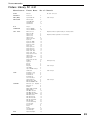
1. Introduction (Version 4.x) ................................................................ 5
1.1 General remarks ........................................................................................ 5
1.2 Specifications and extras ........................................................................... 6
1.3 Installation .................................................................................................. 6
2. Setup ............................................................................................. 7
2.1 Top menu ................................................................................................... 7
2.2 Lamp type .................................................................................................. 8
2.3 DMX output addresses ............................................................................... 9
2.4 Movement direction on DMX mode ........................................................... 10
2.5 Initializing of stage ................................................................................... 11
3. Direct access ............................................................................... 13
3.1 Scan groups and brightness fader ............................................................ 13
3.2 Basic scan functions ................................................................................ 14
3.2.1 Tuning with the encoder .................................................................... 14
3.2.2 Programming of presets .................................................................... 15
3.2.3 Playback of presets .......................................................................... 16
3.3 Movements .............................................................................................. 18
3.3.1 Movement on direct DMX or on stage calculation .............................. 18
3.3.2 Changing the movement mode .......................................................... 19
3.3.3 Transforming memories to a new stage ............................................. 20
3.3.4 Trackball and Mouse ......................................................................... 21
3.3.5 Followspot mode ............................................................................... 21
3.3.6 Circle mode ....................................................................................... 22
3.3.7 Movement speed ............................................................................... 23
4. Memories ..................................................................................... 24
4.1 Programming of basic memories .............................................................. 24
4.2 Playback memories ................................................................................. 26
4.2.1 Playback with programmed x-fade time and trigpoint ......................... 26
4.2.2 Playback with new x-fade time .......................................................... 26
4.2.3 Playback with manual x-fade ............................................................. 26
4.2.4 Freezing of single channels ............................................................... 27
4.2.5 Display of Memory Names ................................................................ 28
4.3 Selective memories .................................................................................. 29
4.3.1 Programming of selective memories .................................................. 29
4.3.2 Playback of selective memories ........................................................ 30
4.4 Modifying of memories ............................................................................. 31
4.4.1 Changing names and parameters ...................................................... 31
4.4.2 Changing matrix and data ................................................................. 31
4.4.3 Copying memories ............................................................................ 32
2
MA Lighting Technology GmbH . Dachdeckerstr. 16 . D-97297 Waldbüttelbrunn . Fax: + 49 9 31 4 97 94 29 . www.malighting.de
Scancommander
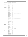
5. Chaser ......................................................................................... 33
5.1 Programming of chasers .......................................................................... 33
5.1.1 New chaser steps ............................................................................. 33
5.1.2 Programming chaser parameters ...................................................... 34
5.1.3 Insert or delete chaser steps ............................................................. 34
5.2 Playback chasers .................................................................................... 35
5.2.1 Enable Chaser .................................................................................. 35
5.3 Modifying a chaser program ..................................................................... 36
5.3.1 Changing names and parameters ...................................................... 36
5.3.2 Changing sequence of steps ............................................................. 37
5.3.3 Changing step matrix and levels ........................................................ 39
6. Sequences ................................................................................... 40
6.1 Programming of sequences ...................................................................... 40
6.1.1 New sequence steps ......................................................................... 40
6.2 Playback of sequences ............................................................................ 43
6.2.1 Playback of a sequence by GO button .............................................. 43
6.2.2 Playback of a sequence with adjusted step rate ................................ 44
6.2.3 Playback of a sequence triggered by sound input .............................. 44
6.2.4 Manual x-fade between sequence steps ............................................ 44
6.2.5 Playback of a sequence with programmed STEP MODE ................... 45
6.2.6 Enable Sequence .............................................................................. 45
6.2.7 Sequence playback menu ................................................................. 46
6.3 Modifying a sequence .............................................................................. 47
6.3.1 Changing sequence step times ......................................................... 47
6.3.2 Changing step sequence and STEP MODES .................................... 48
6.3.3 Changing step matrix and levels ........................................................ 50
6.3.4 Recalling a memory or chaser as step of a sequence ....................... 51
7. REMOTE ..................................................................................... 52
7.1 Remote via Touchboard ............................................................................ 53
7.1.1 Input signal ....................................................................................... 53
7.1.2 Assigning board functions ................................................................. 53
7.2 Remote via DMX input .............................................................................. 54
7.2.1 Input signal ....................................................................................... 54
7.2.2 Assigning board functions ................................................................. 54
7.3 MIDI ......................................................................................................... 55
7.3.1 Choosing the MIDI channel ................................................................ 55
7.3.2 MIDI data format of the Scancommander ........................................... 55
7.4 Master-Slave Operation ........................................................................... 56
7.4.1 Installation......................................................................................... 56
7.4.2 Starting the couple mode .................................................................. 56
7.4.3 Working on master-slave mode ......................................................... 56
7.5 SMPTE TIME CODE ................................................................................ 57
7.5.1 Time Code Network Technics ............................................................ 57
7.5.2 Live recording of a Time Code show .................................................. 58
7.5.3 Time Code Playback ......................................................................... 60
7.5.4 Modifying a Time Code program ........................................................ 61
7.6 The Scancommander Extension Unit ....................................................... 63
eMail: info@malighting.de . Tel.: + 49 9 31 49 79 40 . User's Manual Scancommander
3
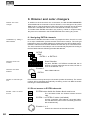
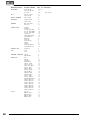
8. Dimmer and color changers ......................................................... 64
8.1 Assigning EXTRA channels .................................................................. 64
8.2 Direct access to EXTRA channels ........................................................ 64
8.3 EXTRA groups and brightness master .................................................. 65
8.4 EXTRA presets .................................................................................... 65
8.5 EXTRA channels in memories .............................................................. 66
9. Utilities ......................................................................................... 67
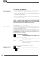
9.1 Display index ........................................................................................... 67
9.2 Storage of programs ................................................................................. 68
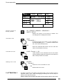
9.2.1 Backup on to memory card ............................................................... 68
9.3 Clearing programs .................................................................................... 70
9.4 Keyswitch ................................................................................................ 70
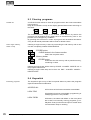
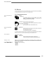
9.5 Macros ..................................................................................................... 71
9.5.1 Programming macros ........................................................................ 71
9.5.2 Macro user examples ........................................................................ 72
10. Inputs and outputs ....................................................................... 73
11. Defining your own Scans ............................................................ 75
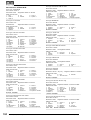
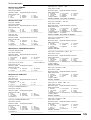
Index ................................................................................................ 79
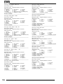
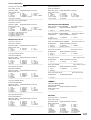
Fixture Library: ................................................................................. 83
Appendix 1:...................................................................................... 87
Appendix 2:.................................................................................... 108
Controlling "TRACKSPOT" ........................................................................... 108
Controlling "INTELLABEAM" ........................................................................ 109
Controlling "Cyberlight" ................................................................................ 111
Safety instructions .......................................................................... 112
Declaration of Confirmity ................................................................ 113
4
MA Lighting Technology GmbH . Dachdeckerstr. 16 . D-97297 Waldbüttelbrunn . Fax: + 49 9 31 4 97 94 29 . www.malighting.de
Scancommander
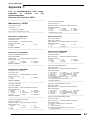
1. Introduction (Version 4.x)
1.1 General remarks
MA Scancommander
basic features
The MA SCANCOMMANDER features perfect and easy control of most DMX
512 compatible moving lights and multifunctional fixtures. Up to 16 units can
be controlled simultaneously.
Main features of the MA SCANCOMMANDER:
- Access to colours, gobos etc. via labelled buttons.
- Programming of selective scenes with - for example - fixed positions but
new colours.
- Transformation of all programs to different stages and different types of
fixtures.
- Followspot via Trackball with several different fixtures.
- Slow fades with freely selectable trigpoint for colours, gobos etc.
- Direct access to all functions during running scenes.
- Fader for direct control of brightness.
- Remote inputs for touchboards, DMX 512, MIDI Sound and SMPTE Time
Code.
- Unlimited number of fixtures by docking several MA SCANCOMMANDERS.
- Simultaneous control of different types of lighting fixtures.
- Additional 96 channels for dimming or color changers.
Chapter 2 describes the set up, which has to be followed step by step:
Choosing lamp type, giving DMX starting address and initializing the stage.
Chapter 3 to 6 describe the direct access to single functions and the
programming of scenes.
Appendix 1 lists the types of fixtures, which can be interfaced to the
MA SCANCOMMANDER.
When you see ">>...." in this menu, there will be further explanations on this
subject. The index at the end makes it easy to find certain subjects.
To be involved in the update service, please fill out the registration
card at the end of the manual.
eMail: info@malighting.de . Tel.: + 49 9 31 49 79 40 . User's Manual Scancommander
5
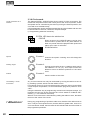
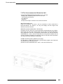
1.2 Specifications and extras
The basic MA SCANCOMMANDER is delivered as a 19" version with 1
desklamp. With this configuration it can perform all functions except labelling
your scenes and presets in the display. There is a list of options available that
will fit your needs.
Trackball,
Computermouse
Makes it easy to control movements. All Atari compatible trackballs or mice
can be used. Note: PC compatible mice cannot be used !!
Keyboard
Enables you to label your programs. Any PC-MF keyboard will work. American keyboards may cause some problems by exchanging different letters.
(>>Memory Names, Preset Names)
Keyboard drawer
The keyboard, offered by MA, can be mounted in a drawer underneath the
SCANCOMMANDER
Board housing
Wooden sides and a front armrest are available.
Backup cue card
All programs can be stored on a memory card in addition to the internal
storage. Cards from 32 to 256 kilobyte, type ITT STAR CARD S-RAM can be
used.
1.3 Installation
Powersupply
100-240 Volt, 40-60 Hz via Euro plug. No switching of voltage necessary.
DMX 512 output
According to USITT DMX 512 (1990) protocol. The output is opto insulated and
even better than RS 485 or RS 422. The pins in the 5 pin XLR plug are: Pin 1:
ground, Pin 2: Data-, Pin 3: Data+ (Pin 4 and 5: not used)
Other in- and outputs see chapter 9.
6
MA Lighting Technology GmbH . Dachdeckerstr. 16 . D-97297 Waldbüttelbrunn . Fax: + 49 9 31 4 97 94 29 . www.malighting.de
Scancommander
2. Setup
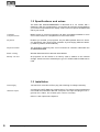
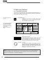
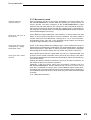
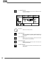
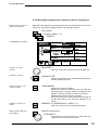
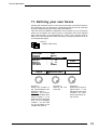
2.1 Top menu
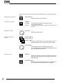
QUIT button (2x)
Top Menu
Starting point for all operations is the TOP MENU. To
go back to the TOP MENU during any operation
press Quit button 2 x.
SETUP
TIME:
PRESET BACKUP REMOTE
14 : 50 : 17
DATE:
RUNNING FADE
+/- 00 %
01 / 16 / 97
V. 4.11
Display buttons
The squares in the display show the current function of your 12 buttons around
the display. The 3 encoders are dedicated to the 3 lower squares of the
display.
Quit button
By pressing the Quit button 2 x you can return to the TOP MENU. The current
operation will be cancelled and the board returns to the normal operation
mode.
Running fade
modification
The encoder wheel no.2 can be used to modify the speed of all active fades
(see 9.1 for details).
eMail: info@malighting.de . Tel.: + 49 9 31 49 79 40 . User's Manual Scancommander
7
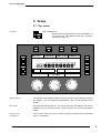
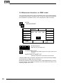
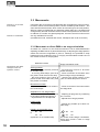
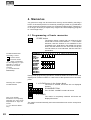
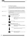
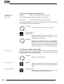
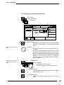
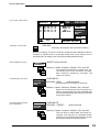
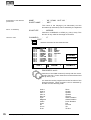
2.2 Lamp type
The MA SCANCOMMANDER is able to control various lamp types. All necessary
adjustments are made by simply choosing a lamp type from the list.
SETUP
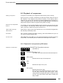
Selecting the
Lamp Type Menu
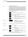
The button on top of the display label "SETUP"
switches the board to the setup menu.
LAMPTYPE
The display shows in 10
sections names of manufactures. MORE turns the
page for more manufactures. The list in the
centre shows the 16
selected lamp types.
For self-defined scans
please choose "User
Scan" (see chap. 11). You
can call 16 different scans
which were defined by
yourself previously.
!
CLAY PAKY
CAMELEON
ITALY
FRANCE
LAMPTYPE
B+K
1 GOLD 2
GERMANY
2 GOLD 2
AMPTOWN
3 GOLD 2
GERMANY
4 GOLD 2
USER SCAN
5 GOLD 2
6 GOLD 2
2
MORE 1(3) 78 GOLD
GOLD 2
SELECT TYPE
GOLDEN SCAN 2
FAL
ITALY
FLY
ITALY
JB
GERMANY
LAMPO
ITALY
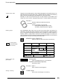
READY
3 ( 12 )
In the "Scan Selection" block the buttons have to be
switched on according the number of scans to be
registered.
Selecting number of Scans
Selecting manufacturer and
lamp type
COEMAR
ITALY
SETUP
9 GOLD 2
10 GOLD 2
11 TIGER
12 TIGER
13 INTEL7
14 INTEL7
15 INTEL7
16 INTEL7
Manufacturer Name
When pushing the desired button, the square of that
manufacturer will be shown inverted.
Encoder 1:
In the lower section of the display you find the first
types of fixtures of the selected manufacturer. Turning Encoder 1 will scroll through the list of available
lamps. If there are "Presets" for the chosen type the
scan type will be shown inversely.
Registration of selected
lamp type
READY
After selecting the desired lamp type, press READY
INIT:SCANS+VALUES+NAMES
All necessary data for this scan type is now
downloaded. The three other kinds of initialization are
for registration of different scan types for simultaneous operation.
8
MA Lighting Technology GmbH . Dachdeckerstr. 16 . D-97297 Waldbüttelbrunn . Fax: + 49 9 31 4 97 94 29 . www.malighting.de
Scancommander
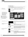
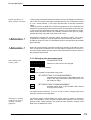
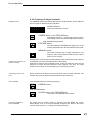
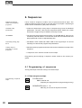
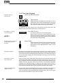
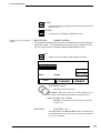
2.3 DMX output addresses
All control signals from the Scancommander are on DMX 512 and are sent on
a two conductor cable to stage. Therefore the single scans need to have a
DMX start address to know, to which data they must respond.. Usually this
address can be selected by a DIL switch directly on the lamp or at their DMX
interface.
On the SCANCOMMANDER these addresses have to be set for the individual
scans.
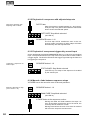
SETUP
DMX
The DMX Output Patch
Menu shows three lists of
16 DMX addresses each.
The first list concerns the
scans, list 2 and 3 are for
additional dimmers and
color changers
(>>Extra1,Extra2) .
PATCH
CLEAR
Scans
Dimmer
EXTRA 1
EXTRA 2
131
1
2
3
4
5
6
7
8
9
10
11
12
13
14
15
16
1 (6)
7 (6)
13 (6)
19 (6)
25 (6)
31 (6)
37 (6)
43 (6)
49 (6)
55 (6)
61 (6)
67 (6)
73 (6)
79 (6)
85 (6)
91 (6)
1
2
3
4
5
6
7
8
9
10
11
12
13
14
15
16
-----------------
(3)
(3)
(3)
(3)
(3)
(3)
(3)
(3)
(3)
(3)
(3)
(3)
(3)
(3)
(3)
(3)
1
2
3
4
5
6
7
8
9
10
11
12
13
14
15
16
-----------------
(3)
(3)
(3)
(3)
(3)
(3)
(3)
(3)
(3)
(3)
(3)
(3)
(3)
(3)
(3)
(3)
SCANS
The square SCANS has to be inverted.
SCAN Selection buttons
Adjusting DMX start
addresses
DMX start addresses have to be set one by one for all
scans. The scans have to be selected by their respective button in the SCAN SELECTION block.
Encoder 1:
Selects the startaddress. An address is only possible to select, if the number of channels, needed for
this scan, is freely available (Number in brackets
shows the number of channels, necessary for the
registered lamptype)
PATCH
(
)
Registers the selected address for the activated Scan.
To go on the next automatically selected scan has to
be chosen.
Clear
Clears the registered address and enables the selection of a new start address.
eMail: info@malighting.de . Tel.: + 49 9 31 49 79 40 . User's Manual Scancommander
9
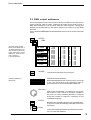
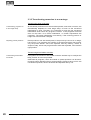
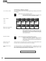
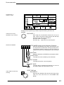
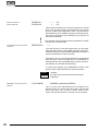
2.4 Movement direction on DMX mode
The movement of the beams can be controlled via two of the encoder wheels,
an external tracker ball or computer mouse. To reach an ergonomic handling of
the trackerball it is possible to do a course adjustment of the movement.
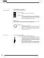
SETUP
DMX MOVEMENT
CENTER
PAN: 128 , TILT : 266
CHANGE
PAN<>TILT
INVERT
PAN
INVERT
TILT
4
PAN
TI
LT
SCAN Selection
Selection of one single scan.
CHANGE PAN<>TILT
Exchanges the DMX signal of the pan and the tilt
channel.
INVERT PAN or INVERT TILT
Changes the direction of the pan or tilt channel.
Using the DMX mode, the values, adjusted on the Scancommanders display,
are send directly as DMX values to the lamps.
Beside this mode the Scancommander offers a stage adapted way of controlling pan and tilt. The difference between this two modes are listed in the
following chapter and in 3.3.1.
10
MA Lighting Technology GmbH . Dachdeckerstr. 16 . D-97297 Waldbüttelbrunn . Fax: + 49 9 31 4 97 94 29 . www.malighting.de
Scancommander
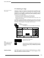
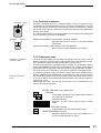
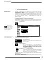
2.5 Initializing of stage
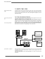
Basic features of movement control
Optionally movement and positions of the light beam are handled as X/Y
coordinates on stage. The value 0/0 corresponds to the middle of the stage.
Changing the X value relates to movement right or left, changing Y moves
between front and backside of the stage. This way of calculation makes it
necessary to do an initialization before starting the programming of scenes,
but gives you a list of advantages
- Programs can be easily transferred to a new stage setup.
- On followspot mode via trackball all beams stay together.
- Moving the trackball or mouse in one direction will move the beam of all
lamps the same direction.
To be able to use these advantages, the stage has to be "shown" to the single
scans. This initialization is done by pointing with the beam to the 4 corners of
the stage. (The most exact way to do this initialization is by using nearly
closed iris or small dot gobo >> see chapter 3 Direct access.)
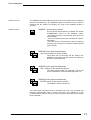
SETUP
STAGE MOVEMENT
The Display shows the MOVEMENT SETUP Menu.
RESET
Center
STORE
PAN: -254 , TILT : 312
CHANGE
PAN<>TILT
INVERT
PAN
INVERT
TILT
SET
SET
SET
4
PAN
SET
TI
LT
SCAN SELECTION block
Selection of one scan.
Note:
RESET data can be used
for controlling the movement, but cannot be
adapted to new stage
setups
Changing movement
directions after RESET
RESET
Clears all former initializations and gives the scan a
standard movement. This is helpful if the movement
of the scan in some way is restricted by a former
initialization.
After RESET (square inverted) the buttons CHANGE PAN<>TILT, INVERT
PAN and INVERT TILT offer the chance of a course adaptation of the
trackerball movement to the beam movement.
eMail: info@malighting.de . Tel.: + 49 9 31 49 79 40 . User's Manual Scancommander
11
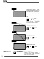
Heading the first corner on the left
backside of stage with the beam (To be
sure to get the same corner points for
all the scans, the corners should be
marked on stage with white tape
crosses.)
As soon as the beam meets the corner
point,
SET
- button
stores the position in a temporary data
register. The mark "
" shows, that
this corner was already adjusted.
Heading the second corner
SET
- button
Heading the third corner
SET
- button
Heading the fourth corner
SET
! Attention !
12
! STORE !
- button
button in the DISPLAY
Initializes the new movement. Changing to
the next scan without STORE will clear the
register of the corner positions.
MA Lighting Technology GmbH . Dachdeckerstr. 16 . D-97297 Waldbüttelbrunn . Fax: + 49 9 31 4 97 94 29 . www.malighting.de
Scancommander
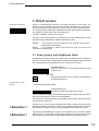
3. Direct access
Actual Scan Selection
There is constant direct access to the single functions of the scans. Any
function can be controlled for a number of scans simultaneously. The LED´s in
the Scan Selection block determine, which of the 16 scans will be affected.
The "CLEAR" button beside the "SCAN SELECTION" block clears the selection,
the "INVERT" button inverts the actual selection.
"CLEAR"-"INVERT" selects all 16 Scans.
As long as the OPTION button is held down, the lower display button on the
left side changes between the SINGLE and MULTI mode.
SINGLE:
Only one scan can be selected at once. All other scans will be
deselected automatically.
MULTI:
It is possible to select more than one scan at a time to be
controlled simultaneously.
3.1 Scan groups and brightness fader
Combinations of scans, which are mostly used, can be stored and recalled as
groups. In the same time, the brightness master underneath the group buttons
are masterfaders for the brightness of this combination of scans.
SCAN Selection
Selection of the scans, which shall be stored as one
of the groups.
STORE
Keep button pressed, select "SCAN" to be displayed
on white background,
Programming of scan
groups
...and simultaneously press...
Group button A-H
Stores the actual scan selection as group.
If you accidentally release the STORE button before pressing a group button,
press two times QUIT to return to the TOP MENU.
Group buttons, when pushed during standard running mode, always overwrite
the actual scan selection.
! Attention !
To have one or more of the scans lighting the stage, at least one of the group
brightness faders has to be up. Even during movement initialization there will
be no beam on stage as long as all group brightness masters are at zero.
! Attention !
The function "MASTERS ALL 100%" at the SETUP menu will set all master
faders to full on. This makes sense during playback of synchronised shows
but should be switched off during standard operation (white background).
eMail: info@malighting.de . Tel.: + 49 9 31 49 79 40 . User's Manual Scancommander
13
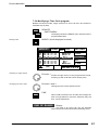
3.2 Basic scan functions
3.2.1 Tuning with the encoder
All functions of a registered lamp can be selected and controlled directly. To
see any effect on stage, every lamp has to be part of at least one of the groups
and its brightness master has to be up.
Controlling functions via
encoder
For any selected function
the DIRECT ACCESS
Menu shows the actual
data in a list at the centre
of the display.
(Right the COLOR display)
FEATURE button
Selection of any function is by their button in the
FEATURE block. As soon as the EXTRA LED lites,
the red printed functions are valid.
VIOLET
GREEN
YELLOW
1
2
3
4
5
6
7
8
RED
WHITE
MORE 1(2)
ORANGE
FEATURE C O L O R
9 WHITE
WHITE
10 WHITE
WHITE
YELLOW 11 RED
YELLOW 12 RED
13 WHITE
WHITE
14 WHITE
WHITE
15 WHITE
89 -16 WHITE
89 --
BLUE
PINK
WHEEL 2
WHEEL 1
SCAN SELECTION
The encoder always controls the scans, which are
actually selected in the selection block. Their numbers in the display list are printed inverted and the
values are modified when the encoder is used.
Encoder 1, 2 and 3
The three lower sections in the display show the
functions, which are controlled by the encoder. The
inside part of the encoder controls the function step
by step, the outside ring offers a fast and course
adjustment. (16 steps per increment).
NOTE:
As it is now possible, to select small beams and to control movement scan by scan, the stage initialization
should be done before going on with programming. This is important to have the chance of transforming
programs to new stage setups. (>>Movement initialization)
14
MA Lighting Technology GmbH . Dachdeckerstr. 16 . D-97297 Waldbüttelbrunn . Fax: + 49 9 31 4 97 94 29 . www.malighting.de
Scancommander
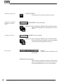
3.2.2 Programming of presets
PRESETS
Using the Encoder Wheels, all functions are controlled in 256 steps. But for
most of the functions there are special values, which are used all the time, like
the single colours on the color channel. These values can be stored together
with a label as PRESETS and can be recalled by the push of a button later on.
On direct access the 12 display sections will show these names. For most of
the scans these PRESETS are stored internally and are downloaded when
doing the lamptype setup. If these PRESETS are not available for the actual
registered lamp type, or they are not right and have to be adjusted, you have to
swop to the PRESET ADJUST menu.
QUIT button
The display switches to the TOP MENU.
PRESET
The display shows the actual output values and the
headline "Adjust Preset".
Feature button
Presets can be programmed for all functions. Also for
PAN/TILT, positions can be prepared as presets.
Display button of the desired square
Short push (<1/2 sec.) of a button inverts the square.
PRESET names
KEYBOARD
Input of a name with up to 6 characters.
ENTER or RETURN (KEYBOARD)
Stores the name for the preset.
Adjusting values
Saving a PRESET
Adjustment of values via SCAN SELECTION and ENCODER 1 to 3.
1. x STORE button
All Scans, where the function is available, are selected
2. x STORE button
For all selected scans the actual output values are
stored as PRESET.
Testing and modifying
PRESETS
Preset button pressed for more than 1/2 sec
The selected PRESET will be recalled and can be
modified and stored.
After the second STORE the next PRESET can be programmed or the desk
will return to the TOP MENU by using the QUIT button.
eMail: info@malighting.de . Tel.: + 49 9 31 49 79 40 . User's Manual Scancommander
15
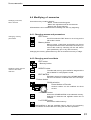
3.2.3 Playback of presets
Playback PRESETS
(X-Fader in the Feature block zero)
Feature Button
Selects a function for direct access.
Display buttons
In direct access mode preprogrammed PRESETS
can be recalled by their button. Similar to the control
via encoder, only the scans which are actually
selected, will change to the new value.
Display list:
If the actual value of a scan was selected by recalling a preset, the list will no
longer show the channel value, but will show the preset name.
Encoder 1 to 3
Modifications via encoder:
- Any modification via the encoder will change the
display to show the actual output value. If the value
returns to the preset value, the display returns to
show the preset name.
Preset X-Fades
Slow x-fades to a preset value:
X-FADER (FEATURE SELECTION BLOCK)
The x-fader in the feature selection block sets the
time for the slow fade. On any recall of a preset, while
this fader is raised to a value above zero, the channels
will slowly change from their actual output value to
the value stored in the preset.
When recalling a preset for a switch function like
gobo, this fader should be down, otherwise the gobo
wheels will slowly change to the selected new gobo.
16
MA Lighting Technology GmbH . Dachdeckerstr. 16 . D-97297 Waldbüttelbrunn . Fax: + 49 9 31 4 97 94 29 . www.malighting.de
Scancommander
SAMPLE function
SAMPLE display
The SAMPLE function enables the recall of up to nine presets even for different
features simultaneously. The SAMPLE preset commands can be created in
advance and are listed in the display, as soon as the SAMPLE button is
pressed.
SAMPLE - keep button pressed
As long as the sample button is pressed, the SCANCOMMANDER works in the SAMPLE mode.
- the display shows a insert window with up to nine
preset recalls.
- Preset commands will not be executed but listed in
the Display
- The GO+ button of the sequence will not recall the
next step of the sequence, but will recall the sampled
preset recalls.
SAMPLE button and simultaneously
any Preset button in direct access
The Preset are not executed, but are listed in the
SAMPLE list together with the actual scan selection
and the actual x-fade time.
SAMPLE button and simultaneously
GO + button of the sequence section
The listed preset recalls get executed. The list will
not be cleared and can be recalled again later on.
SAMPLE button and simultaneously
CLEAR button in the feature section
The SAMPLE list will be cleared.
Any new preset command, which is sampled in the list, may overwrite and
therefore automatically clear a former command. (For example if a new
command sets a gobo for all scans, any former gobo commands in the sample
list are cleared.)
eMail: info@malighting.de . Tel.: + 49 9 31 49 79 40 . User's Manual Scancommander
17
3.3 Movements
PAN/TILT via encoder
and Presets
PAN/TILT coordinates
Controlling the movement works basically like controlling any other function.
Positions, which are stored as presets, can be recalled by their buttons. The
scan selection block shows, which of the 16 scans will go to the new position.
When a preset is recalled with a x-fade time greater than zero, the beams will
change slowly and with a linear travel from their actual position to the new one.
In addition to encoder and preset playback, there are some functions which
are only available for Pan/Tilt.
(two different mode, trackball and mouse, followspot and circle movement)
3.3.1 Movement on direct DMX or on stage calculation
As noted in 2.4 and 2.5 on the Scancommander it can be selected between
adjusting the DMX values of pan and tilt directly or adjusting the stage position
where the scans are supposed to point to. Although it is possible to swap
between this two modes any time, it is highly recommended to select one of
the modes as basic for all programs.
DMX direct mode
Advantages and disadvantages of the two
operation modes
Setting position:
- better control in extreme positions
far outside stage
- on moving head lamps, pan turns
the yokes while tilt turns the lamp
- the bump position of the yokes is
placed at the same side every time
the picture is recalled.
- synchronously control of all scans
within the stage
- linear movement of the beam even
when using moving head lamps.
- reaching the bump position of the
yoke, the head lamp turns around.
Movements on fade:
- depends on mechanical construction of the lamps
- linear movement of the beam within
the stage area
Adaptation to new stage setups:
- scans have to be mounted exactly
to the same position as before or
- all presets have to be adjusted
- adapting all programs by initializing
the 4 corners
- adjustment of single presets
Follow mode:
- not possible
Display on the pan/tilt menu:
00
00
to
FF
FF
(optional in % or hexadecimal)
18
Stage calculation mode
- without any problem up to 50% outside stage
-99
- 99
to
99
99
the rhomb marks stage coordinates,
white ramp marks a fade to stage
coordinates
MA Lighting Technology GmbH . Dachdeckerstr. 16 . D-97297 Waldbüttelbrunn . Fax: + 49 9 31 4 97 94 29 . www.malighting.de
Scancommander
Special regulations on
stage oriented movement
! Attention !
! Attention !
- During stage oriented movement mode the value in the display reaches from
-99 to +99. The centre of the stage corresponds to 0/0, the corners have values
of +/-25. Values outside +/- 25 mean, that the beam is actually outside the
stage.
- When a preset is recalled with a x-fade time greater than zero, the beams will
change slowly and with a linear travel from their actual position to the new one.
- If the movement initialization was done correctly, any combination of scans,
which shows the same values in the display, meet the same point on stage.
Outside the stage, this effect will loose its accuracy.
Programming presets for Pan/Tilt makes movement control very handy.
44 positions on stage can be preprogrammed and recalled by their button.
In addition it helps to return to a well defined point if the operation via trackball
gets confusing.
During any programming of positions make sure, that the circle radius is set to
zero. If only the circle speed is zero, but the radius is greater zero, there is no
circle movement visible, but the radius is still valid and will cause an offset on
the programmed positions.
3.3.2 Changing the movement mode
Direct setting of the
working mode
SCAN SELECTION
Selection of the scans to be changed
OPTION button
keep button pressed and simultaneously press
SET SELECTION TO STAGE MOVEMENT
selected scans, which work on direct DMX mode, will
swap to the stage calculation mode and jump to "00
00" middle of stage.
SET SELECTION TO DMX MOVEMENT
selected scans swap to direct DMX mode without
changing their position.
The actual mode is marks by "S" or "D" for all 16 scans. Changing the mode
via option cancels all running fades.
Changing the working
mode can be done by
recalling according
playbacks
The working mode is stored within any preset, memory, chaser or sequence
step. The playback of this programs automatically restores the according
working mode. Fades between two positions with different working mode
always run in DMX direct mode.
eMail: info@malighting.de . Tel.: + 49 9 31 49 79 40 . User's Manual Scancommander
19
3.3.3 Transforming memories to a new stage
Transforming stage mode data:
Transforming programs to
a new stage setup
All movement positions which are stored as presets, memories or scenes, are
automatically adapted to a new stage setup, as soon as the movement
initialization is done. Therefore it is important to have the first movement
initialization done before any program is stored. If the programs had been
done on the basic of an exact initialization, no further adjustments are
necessary. The same initialization is necessary, if the mounting position or
height of a scan has been changed.
Adjusting preset positions
Preset positions can also be adjusted, if the point they have to hit on stage,
has moved. If, for example, the position of the keyboard player has moved,
only the preset "KEYB." has to be adjusted, and any memory, chaser or
sequence step, which was programmed to meet the keyboard, will recall the
right position.
Transforming direct DMX mode data:
Transforming direct DMX
memories
20
If programs are stored on direct DMX mode the easiest way is to adjust the
lamp position as exact as possible.
Otherwise all programs, which are based on preset positions can be transformed by simply adjusting the 44 preset positions. Stage pictures, which are
not based on presets, have to be tested and adjusted one by one.
MA Lighting Technology GmbH . Dachdeckerstr. 16 . D-97297 Waldbüttelbrunn . Fax: + 49 9 31 4 97 94 29 . www.malighting.de
Scancommander
3.3.4 Trackball and Mouse
Slow/Fast On/Off
Slow/Fast
On/Off
An Atari compatible mouse or trackball makes control of movement very
comfortable. In standard operation mode, no follow spot fixed (see 3.3.3), the
mouse will always control the actual selected scans simultaneously. Unlike
the control via encoder, the mouse even works when Pan/Tilt is not selected in
direct access mode.
The mouse buttons switch the working modes, the new mode will be displayed
for one second in the centre of the display.
Right mouse button (outer buttons on the trackball):
Switches the mouse on and off, to avoid accidental
movements.
Left mouse button (inner button on the trackerball)
Mouse speed changes between slow and fast.
3.3.5 Followspot mode
Followspot in standard
operation mode
Fixing the followspot
mode
The Pan/Tilt calculation via the stage coordinates has the effect, that all
beams, starting at the same point, stay together during simultaneous operation. Outside the stage this effect looses part of its accuracy.
To have a real tracking of a person moving on stage, it is necessary to do the
movement initialization of the four corners at about 1.5 m height, otherwise the
beams will perfectly light up the feet of the person, but not the body. Therefore
the corners have to be marked by a microphone stand or something similar.
In standard operation mode, the mouse controls the actual selected scans.
Using the EXTRA-FOLLOW feature, it is possible to fix one group of scans to
the mouse. Any change of the scan selection while controlling colours, gobos
or any other feature, will not affect the follow selection. The mouse will go on to
control their scans.
Additionally the scans, fixed to the follow mode, won't be affected by any
memory or playback program.
EXTRA LED has to be switched on
FOLLOW
The display changes to FOLLOW FIX Menu with the
list of Pan/Tilt coordinates.
SCAN Selection
Selection of scans, which shall be fixed to follow
mode.
FREEZE FOLLOW inverted
The selected scans are fixed to follow mode.
MODE PROGRAM inverted
Standard operation mode. The mouse always controls the actual selection of scans.
eMail: info@malighting.de . Tel.: + 49 9 31 49 79 40 . User's Manual Scancommander
21
3.3.6 Circle mode
Circle movement as a
Feature
The feature EXTRA - CIRCLE offers direct control of circle movements. The
actual Pan/Tilt position will be the centre point of the circle movement, radius
and speed can be controlled by encoder. By moving the Pan/Tilt position, the
circle will move simultaneously.
Circle parameters can be stored as presets like any other feature and can also
be stored within memories, chasers or sequence steps.
(>>Programming selective memories).
EXTRA LED has to be switched on
CIRCLE
Direct access to the CIRCLE feature can be done
with encoder or presets like on any other feature. At
least one preset should be prepared with speed and
radius set to zero for all scans.
SCAN Selection
Speed
Encoder 1
Controls the speed. Crossing zero will change the
direction.
Starting angle
Encoder 2
As long as the radius is zero, a starting angle can be
set between 0 to 15 (=F). This helps to start the
different scans at different positions of the same
circle.
Radius
Encoder 3
sets the radius of the circle.
22
Terminating a circle
movement
Any circle movement can only be terminated by turning the radius to zero or
by recalling a preset, which sets the radius to zero.
For keeping control of circle movements and to have the chance to terminate
circles as quick as possible, it is recommended to program a preset for circle
"OFF".
Using the selective way of programming memories and sequence steps, it is
important to have one of the memories S1 to S10 stored as "CIRCLE OFF"
memory. (>> 4.3 Selective memories)
When a circle movement is terminated by setting the radius to zero, the beam
returns to the centre of the circle.
! Attention !
During any programming of positions make sure, that the circle radius is set to
zero. If only the circle speed is zero, but the radius is greater zero, there is no
circle movement visible, but the radius is still valid and will cause an offset on
the programmed positions.
MA Lighting Technology GmbH . Dachdeckerstr. 16 . D-97297 Waldbüttelbrunn . Fax: + 49 9 31 4 97 94 29 . www.malighting.de
Scancommander
3.3.7 Movement speed
Handling within the
Scancommander
Slow movements are one of the major applications of moving lights. The
MA SCANCOMMANDER controls fades by updating the position about 40
times a second. The intern resolution of the SCANCOMMANDER is 1600
steps for Pan and 1600 steps for Tilt. Using one or two channels per direction,
the Pan/Tilt informations can be sent with 8 to 16 bit accuracy. Depending on
the lamp type, the single steps of the SCANCOMMANDER will be conducted
with individual degree of accuracy.
Lamp types with 10 to 16
BIT accuracy
As the DMX 512 signal features a 8 bit resolution, it offers control with 256
steps. A much improved movement control is possible, if the lamp offers a
second channel for fine adjustment, reaching a 10, 12 or 16 bit resolution.
Unfortunately today only few of the available lamps feature this second
channel for high resolution control via DMX 512.
Lamp types with smooth
movements by creating
intermediate steps
Some of the lamps feature an intelligent logic, which enables the lamp to
make smooth movements by creating their own intermediate steps. Therefore
these lamps show a little delay on slow movement (Hysteresis). Especially
when doing the movement setup, this may cause some loose of accuracy.
Lamp types with a speed
channel
Other lamps require that the speed data are sent on a separate DMX 512
channel. As this speed information has to be set by the user any time there
are changes between fast movement and slow fades or follow spot operations,
it is not very handy.
Setting this speed to maximum leaves no chance to do slow movements, as
the lamps will jump from position to position.
Appendix 1 lists the scans, which will successfully interface with the
MA SCANCOMMANDER. Unused features such as focus or zoom can be
used as a makeshift for lamps which need additional speed information.
Controlling the movement speed of these scans can be done by programming
some selective memories on S1 to S10, which only set a value on to the speed
channels.
(>>4.3 Selective memories)
eMail: info@malighting.de . Tel.: + 49 9 31 49 79 40 . User's Manual Scancommander
23
4. Memories
Any picture on stage can be stored as a memory and recalled by touching a
button. If the actual position is created by recalling a preset, any modification
of this preset will cause the memory to recall the modified values. Therefore it
is no longer necessary to adjust every single scene when adapting programs
to a new stage setup.
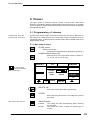
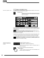
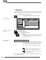
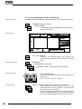
4.1 Programming of basic memories
STORE button
The display shows a matrix with 16 columns for the
scans and 12 rows for the features. "-" in the matrix
indicates, that this feature is not available for the
registered scan. Small dots in the middle of a square
show, that the feature for this scan was set by the
encoder wheel, a cross indicates, that the value is a
presetvalue.
STORE MATRIX when
controlling 6 scans.
Preset values
Encoder values
Stage coordinates
For the beginning it is just
important, to have all
squares in the matrix
inverted.
(>> 4.3 SELECTIVE
MEMORIES)
SCAN No: 1 2 3 4 5 6 7 8 9 10 11 12 13 14 15 16
SHUTT
IRIS
FOCUS
C-M-Y
PRISMA
COLOR
DIMMER
GOBO
MOVE
CIRCLE
SPEED
ROTAT.
EXTRA 1
EXTRA 2
During initial programming operations, all blocks within the matrix have to be
displayed in inverted contrast. In case some of the squares are not inverted,
press
Selecting the complete
STORE MATRIX
1. x CLEAR button in the feature block
The matrix is cleared, all blocks are not displayed
inverted.
SCANSELECTION
Use -CLEAR - INVERT to select all scans
2. x CLEAR
Note: if the STORE
MATRIX is not completely
selected, only some of the
adjustments on stage are
stored.
(>> 4.3 Selective Memories)
24
The matrix is completely selected. All blocks are
displayed inverted.
The matrix is stored internally and reconstructed as soon as the next picture
is stored.
MA Lighting Technology GmbH . Dachdeckerstr. 16 . D-97297 Waldbüttelbrunn . Fax: + 49 9 31 4 97 94 29 . www.malighting.de
Scancommander
Trigpoint and x-fade
Features may be selected for slow infade (indicated by the small ramp) or for
fast switching to the new value (trig). A trigpoint will set, whether the switching
will be done at the beginning, the middle or the end of the fade.
Example: A scan may move slowly from its old position to the middle of the
stage, the color is set to change quickly at 50%, means middle of the travel.
Encoder 1
Selects a feature marked by an arrow.
Encoder 2 or 3
Switches between Trig and fade.
Ramp (black triangle): Slow x-fade
No Ramp :Switching at the Trigpoint
Memory pages
the PLAYBACK area right hand on the front panel offers 40 buttons for
memories, whereas the upper 30 buttons can be switched to 4 different pages
A to D. The right hand buttons with two LED´s are able to contain chasers. A
flashing LED in a page button shows the preselected page. The lower ten
memory buttons S1 to S10 stay untouched by the page buttons and should be
programmed to contain the mostly used memories.
MEMORY button/ (PAGE A-D)
Selects a place to store the picture as memory.
A small graphic
shows the STORE
matrix of this memory
PROGRAM
A 2
MEMORY:
FREE:
MEMORY
(84233)
NO NAME
TRIG
FADE 0.0 sec
Memory name and
parameters
0%
KEYBOARD
Input of a name with up to 14 characters.
ENTER or RETURN (Keyboard)
Stores the name.
Encoder 1 and 3
Sets x-fade time and trigpoint.
Storing a memory
STORE button
Saves the actual stage as a memory.
eMail: info@malighting.de . Tel.: + 49 9 31 49 79 40 . User's Manual Scancommander
25
4.2 Playback memories
Standard Memories
Memories can be recalled by their respective buttons any time. All channels,
which had been selected in the store matrix, will be set to a new value.
Therefore standard memories with completely selected store matrix will recall
one well defined picture on stage. The LED in the last recalled memory lites
up.
4.2.1 Playback with programmed x-fade time and trigpoint
Preprogrammed fade
time
For any feature which was set to x-fade mode (small ramp in the store matrix),
the output will not switch to the new value but will change slowly with the
programmed fade time.
The output of the trigger features will switch as quickly as possible to their new
value. The time of switching is set by the trigpoint.
4.2.2 Playback with new x-fade time
Overwriting the programmed fade time
FADE MODE switched to SET TIME
X-Fader in the playback section
The x-fader will now overwrite the programmed fade
time.
Switching features will adapt their trigpoint according
the new fade time.
Memory button
Recalls the memory with the adjusted fade time.
4.2.3 Playback with manual x-fade
Manual cross fades
FADE MODE switched to MAN FADE
As soon as the fader is moved to one of the end
positions (LED on), a memory can be loaded for
manual crossfade.
X-FADER
Moving the fader will crossfade the values between
the start position and the new memory.
MEMORY button during running fade
FADE LED flashes and the memory will be recalled
with its stored fade time.
26
MA Lighting Technology GmbH . Dachdeckerstr. 16 . D-97297 Waldbüttelbrunn . Fax: + 49 9 31 4 97 94 29 . www.malighting.de
Scancommander
4.2.4 Freezing of single channels
FREEZE button
The FREEZE function fixes the actual value of single channels. These channels
will no longer be affected by any playback.
SCAN Selection
Select a combination of scans
FREEZE button in the FEATURE block
keep button pressed ...(The display shows a matrix.
The already frozen channels are displayed inverted.)
and simultaneously press
FEATURE button
The LED inside the FREEZE button lights up. For the
actually selected scans the selected feature is fixed.
MEMORY button
The fixed channels get no longer affected by any
memory, even if they had been selected in the store
matrix of this memory.
Changing the selection of
frozen channels
Changing the scan selection and pushing another feature button will create a
combination of frozen channels shown in the display.
Selecting a feature where already some scans are fixed will clear the old
selection of scans and will freeze the new selection. This way, for single
features, the Freeze can be cleared by not selecting any scans.
Controlling frozen channels
Direct Access via presets or encoder will work even on frozen channels. The
Freeze only protects against playback buttons like memories.
Clear FREEZE
The complete freeze is cleared by pushing
FREEZE button...
and simultaneously ...
CLEAR button in the FEATURE block
The LED in the FREEZE button is dark.
Automatic FREEZE on
FOLLOW MODE
All scans fixed to follow effect by EXTRA FOLLOW Mode are frozen
automatically. This is to avoid accidental changes of the beams, which are
used to track a person. (>>Fixing the followspot mode)
eMail: info@malighting.de . Tel.: + 49 9 31 49 79 40 . User's Manual Scancommander
27
4.2.5 Display of Memory Names
List of memory names
The names of the memories, set during programming or editing, can be listed
in the display.
LIST button at the playback section
As long as the button is pressed, the display will
show the names of the actual memory page.
Upper 5 buttons
2. line
3. line
4. line
..
..
Memory S1 to S10 are the
same on all 4 pages
MEMORY
A/01
MEMORY
A/06
MEMORY
A/11
MEMORY
A/16
MEMORY
A/21
MEMORY
A/26
S/01
S/06
MEMORY
A/02
MEMORY
A/07
MEMORY
A/12
MEMORY
A/17
MEMORY
A/22
MEMORY
A/27
S/02
S/07
MEMORY
A/03
MEMORY
A/08
MEMORY
A/13
MEMORY
A/18
MEMORY
A/23
MEMORY
A/28
S/03
S/08
MEMORY
A/04
MEMORY
A/09
MEMORY
A/14
MEMORY
A/19
MEMORY
A/24
MEMORY
A/29
S/04
S/09
MEMORY
A/05
MEMORY
A/10
MEMORY
A/15
MEMORY
A/20
MEMORY
A/25
MEMORY
A/30
S/05
S/10
When releasing the button, the desk will return to the
last display. This list can be recalled any time, even
during STORE or EDIT function, without interrupting
the actual procedure.
Permanent display
LIST double click (2 x pushing within 1/4 sec.)
Outside STORE, EDIT or MODIFY the list can be
recalled for permanent display by a double click. It
automatically switches off when using the display for
any other function.
28
Display buttons and
encoder locked
All the functions of the desk remain untouched, but the display buttons and
encoders will be cancelled as long as the list is in display.
Setting names via keyboard
The names of memory 1 to 30 are displayed with 2 x 7 characters. S1 to S10
get 7 characters each. When typing the name during STORE or EDIT, small
arrows mark the beginning of the second 7 characters.
MA Lighting Technology GmbH . Dachdeckerstr. 16 . D-97297 Waldbüttelbrunn . Fax: + 49 9 31 4 97 94 29 . www.malighting.de
Scancommander
4.3 Selective memories
Working mode of
selective memories
Memories and scenes may be programmed in a way, that they only affect
selected channels. When this memory is recalled by its button, all other
channels stay untouched.
Example: a memory may be supposed to recall only a new color for scan
numbers 1 to 6. The position of the beams, the gobos and all other functions
stay unchanged, when this memory is recalled. Scan no.7 to 16 stay completely untouched.
4.3.1 Programming of selective memories
The STORE MATRIX, displayed any time the STORE button is pushed to save
a picture, marks out, which of the channels will be controlled by this scene.
STORE button
SCAN No: 1 2 3 4 5 6 7 8 9 10 11 12 13 14 15 16
SHUTT
IRIS
FOCUS
R-G-B
PRISMA
COLOR
DIMMER
GOBO
MOVE
CIRCLE
SPEED
ROTAT.
EXTRA 1
EXTRA 2
A small copy of
this matrix will be
displayed during the next
step and during any edit
or modify operation.
Selecting single channels
in the STORE MATRIX
Unlike programming standard memories, on programming selective memories
only a part of the channels are selected.
SCAN Selection
Selects the scans which will be affected by the
following feature
.
FEATURE button
For the actual selection of scans, this feature is
selected. Selected channels are displayed inverted.
Changing the scan selection before pushing the next
feature button enables you to select any free
combination of channels.
(
)
CLEAR button in the FEATURE block
Clears the complete matrix. The second CLEAR will
select all features for the selected scans. The third
CLEAR selects all features for all scans.
The further procedure of storing selective memories is the same as storing
standard memories.
The modified STORE MATRIX is saved internally and reconstructed as soon as
the next STORE operation starts.
eMail: info@malighting.de . Tel.: + 49 9 31 49 79 40 . User's Manual Scancommander
29
4.3.2 Playback of selective memories
Recalling selective memories works the same way as recalling standard
memories, but there are some advantages on programming selectively
Free combination of a number of selective memories:
A memory, setting the position of the scans can join
together with pure color memories or pure gobo
memories. The same color memory may be recalled
during a running chase for movement. Operating in
this way saves time when programming up and saves
storage capacity.
Saving storage capacity:
On a selective memory, only the data of the selected
channels get saved. Using selective memories
enlarges the number of chaser steps possible to
program later on.
Drawback of selective programming:
Using selective programs requires a good overview of
the stored programs. As selective memories affect
only selected channels, the picture they produce on
stage may be different depending on the picture
before.
Example: If the beams are doing a circle and a new
memory only contains a new pan/tilt position, pushing this memory will only move the centre of the
circle to the new position but will not stop the circle
movement. To stop the circle and to send the scans
to a new and well defined position, the new memory
needs to contain the information "Set radius to 00"
and CIRCLE has to be selected in its STORE MATRIX
for all the scans.
To avoid confusion on using selective memories, the
memories S1 to S10 should be programmed to contain
some standard memories with fully selected STORE
MATRIX.
In addition there should be some "Stop" memories
like "Circle Off", which only set the circle radius to 0
for all the scans, or "Shutter Strobe Off".
30
MA Lighting Technology GmbH . Dachdeckerstr. 16 . D-97297 Waldbüttelbrunn . Fax: + 49 9 31 4 97 94 29 . www.malighting.de
Scancommander
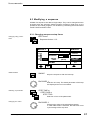
4.4 Modifying of memories
Modifying memories,
basic structure
A stored memory contains data for:
- Name, x-fade time and trigpoint
- Matrix with trig/fade marks for the features
- Data for the single channels
All these data can be modified without starting from the very beginning.
4.4.1 Changing names and parameters
Changing memory
parameters
EDIT button
the LED inside this EDIT button is on as long as the
edit mode is active.
Memory button
Memory name, x-fade time and trigpoint can be set
via keyboard and encoder. Select the next memory or
cancel edit mode by switching off the edit button
(also possible by quit or any direct access.)
Changing the memory parameters only will not recall this memory to stage.
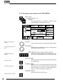
4.4.2 Changing matrix and data
EDIT button
Memory button
Modifying single channel
values or the matrix
selection
MODIFY button
The selected memory gets recalled to stage and the
block "MODIFY" is displayed inverted.
EDIT MATRIX
Edit Matrix has to be inverted, if the STORE MATRIX
has to be checked or modified within the next steps.
Feature button
SCAN selection
Preset button or Encoder
Channel values can be modified via direct
access.
1.x STORE button
Shows the STORE MATRIX of the selected memory.
Selection of channels and trig/fade marks can be
modified.
2.x STORE button
Saves the modified memory.
The STORE MATRIX of the last modified memory stays in the temporary
storage and will be reconstructed when doing the next store operation.
eMail: info@malighting.de . Tel.: + 49 9 31 49 79 40 . User's Manual Scancommander
31
4.4.3 Copying memories
By recalling
EDIT Memory A -
COPY MEMORY button on the display
keep button pressed and simultaneously press ...
Memory B
Copies the memory including name, fadetime and
trigpoint settings.
Copy is possible between standard memories, but not possible between
chases or sequences.
32
MA Lighting Technology GmbH . Dachdeckerstr. 16 . D-97297 Waldbüttelbrunn . Fax: + 49 9 31 4 97 94 29 . www.malighting.de
Scancommander
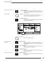
5. Chaser
The right column of memory buttons contain a second LED. With these
buttons it is possible to program single stage scenes as memories or complete
chaser programs. Chaser programs are just a list of scenes which change with
preselected step time.
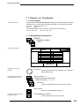
5.1 Programming of chasers
Programming steps like
programming memories
Programming chaser steps works like programming a memory. Whereas an
old memory is erased as soon as a new stage scene is programmed to its
respective button, scenes stored to a chaser button will be added to the list of
steps already stored.
5.1.1 New chaser steps
STORE button
Matrix can be set
(Prepare your stage plot like on programming memory.)
CHASER button (Page A-D)
Selecting one of the right side memory buttons (5,
10, 15, 20, 25, 30, S5 or S10)
DELETE
ALL
INSERT
A small graphic
shows the STORE
Matrix of this step
PROGRAM
1
2
......
)
CHASE
CHASE:
A 25
LINK FADE
STEPS:
FREE:
2
STEP FADE
0.00 sec
STEP TRIG
0%
SPEED
3
(
SINGLE
(94770)
0.500 HZ
2.000 Sec
DELETE ALL
Clears the chase and erases all old steps.
STORE
Saves the stage picture as a new step at the end of
the chase
Stop chaser after one run
SINGLE square
Inverted:
Normal:
The chaser will stop automatically when reaching
the last step
The chaser will return to step one and will go on
running.
eMail: info@malighting.de . Tel.: + 49 9 31 49 79 40 . User's Manual Scancommander
33
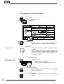
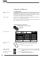
5.1.2 Programming chaser parameters
CHASER SPEED
STEP FADE
STEP TRIG
SPEED
- sets the time between the different steps
STEP FADE- sets the x-fade time between the single steps
STEP TRIG
- sets the trigpoint between the single steps
As the STORE MATRIX may be different from step to step, the listed parameters
are global for the complete chaser program.
Encoder 2
Speed in Hertz (steps / sec.) and in seconds.
STEP FADE or
STEP TRIG
Inverts the respective block in the display. In case
LINK FADE is selected, the fade time is set in
percentage of the step time
Encoder 3
Changes the selected parameter. The step fade is
allowed to be longer than the step time (SPEED).
This makes sense if the fading channels are not
selected in the next step. Otherwise they will not find
the time to do their fade. (>> selective programming)
5.1.3 Insert or delete chaser steps
Step sequence
Any time a chaser button is selected to store a new step, the step counter will
automatically jump to the old step number + 1. This way the new picture will
be added as the new last step of the chaser.
Encoder 1
Selection of a step number.
Insert a new step
INSERT
Shifts the selected step and all following steps one
step back and inserts the new picture at the selected
place.
Overwrite an old step
STORE button
Overwrites the selected step by the new picture. The
total number of steps stays unchanged.
34
MA Lighting Technology GmbH . Dachdeckerstr. 16 . D-97297 Waldbüttelbrunn . Fax: + 49 9 31 4 97 94 29 . www.malighting.de
Scancommander
5.2 Playback chasers
Start a chaser
Chaser programs are recalled by their respective buttons like any other
memory. Each step will control output channels according to its STORE
MATRIX. Selective programmed steps keep deselected channels untouched.
Termination of a chaser
A second push on a chaser button will not stop the chase but will make it start
again with step number one. On the MA SCANCOMMANDER always the
latest pushed button has the highest priority. To stop a running chaser, all the
channels, which are actually controlled by the chaser steps, have to be
overwritten by recalling a memory or preset in direct access.
Partly overwriting a
running chaser
Recalling selective memories may overwrite parts of the channels, controlled
by the chaser. Therefore the chaser looses its priority on these channels,
whereas other channels may still be controlled by the next chaser steps.
A chaser may control color, and movement of the scans. If the
color has been overwritten by recalling a pure color memory or
any color preset in direct access, the chaser will still go on to
control movement, but it has no longer priority over the color. This
makes it possible to do the same movement with different colours.
In the same way a selective memory may control all features of
only one or two scans. Recalling this memory after starting a
chaser will cut down the effect of the chase as it can no longer
control these scans. The rest of the scans will continue with the
chaser steps.
Freezing single channels
Channels, fixed to their value by the FREEZE function, will no longer be
affected by chaser steps. After clearing the FREEZE the chaser resumes
control of these channels.
5.2.1 Enable Chaser
Chaser recall without
going back to step 1
The ENABLE function allows the chaser to resume control of all channels
without starting at step 1.
ENABLE button at the sequence section.
Keep button pressed ...
... and simultaneously press ...
Chaser button
The next step of the chaser is enabled to control all
channels according its step matrix.
eMail: info@malighting.de . Tel.: + 49 9 31 49 79 40 . User's Manual Scancommander
35
5.3 Modifying a chaser program
A stored chaser program contains data for:
- Name, SPEED, STEP FADE time and STEP TRIG
Point
- a STORE MATRIX per step
- a set of single channel values per step
5.3.1 Changing names and parameters
EDIT button
Chaser button
SINGLE
MODIFY
EDIT
1
2
......
3
On Line changing of the
chaser parameters
CHASE
CHASE:
A 25
LINK FADE
STEPS:
FREE:
2
STEP FADE
1.00 sec
STEP TRIG
0%
SPEED
(94770)
0.500 HZ
2.000 Sec
Encoder 2
Changing the SPEED of the chase on line.
STEP FADE or
STEP TRIG
Selection of a parameter.
Encoder 3
Changing the selected parameter. In case LINK FADE
is selected, the fade time is set in percentage of the
step time.
Any change of the parameters will work directly on the running program.
Keyboard with ENTER or RETURN
Input of a new name.
36
MA Lighting Technology GmbH . Dachdeckerstr. 16 . D-97297 Waldbüttelbrunn . Fax: + 49 9 31 4 97 94 29 . www.malighting.de
Scancommander
5.3.2 Changing sequence of steps
EDIT button
Chaser button
MODIFY
Modify mode shows the
steps on stage
The selected step will be recalled to stage and the
block MODIFY is displayed inverted.
MODIFY
MAKE
BLOCK
1
2
3
4
5
6
EDIT
......
EDIT
MATRIX
CHASE
CHASE:
A 25
STEPS:
FREE:
6
DELETE
STEP
DOUBLE
STEP
(94120)
3
Testing of the steps
Encoder 1
Scrolls through the steps and recalls the steps on
stage.
Deleting a step
DELETE STEP
Erases the selected step and shifts all following
steps one step ahead.
Creating a new step
DOUBLE STEP
Makes a copy of the selected step and inserts this
copy right in front. The new step may now be modified.
(see >> 5.3.3 Changing step matrix and levels)
Block operations
1. x MAKE BLOCK
Inverts the menu block contrast. The block operation
mode starts, where a complete set of steps can be
handled simultaneously.
Encoder 1
Selects steps for the following block operations. The
number of the selected steps are displayed inverted.
eMail: info@malighting.de . Tel.: + 49 9 31 49 79 40 . User's Manual Scancommander
37
2. x MAKE BLOCK
The four sections on top show the different block
operations available.
MOVE
BLOCK
1
2
3
4
5
6
......
COPY
BLOCK
DELETE
BLOCK
EDIT
CHASE
CHASE:
A 25
STEPS:
FREE:
6
(94770)
CANCEL
BLOCK
BLOCK
START:
STEP 3
END:
STEP 5
INFO
7
Encoder 1
Selects a new step number.
MOVE BLOCK
Moves the sequence of steps, marked as block, to
the new address. The total number of steps stays
unchanged.
COPY BLOCK
Makes a copy of all the steps in the block and inserts
these steps at the new address
DELETE BLOCK
Deletes all steps marked as block and shifts the
following steps ahead.
CANCEL BLOCK
Cancels the block operation mode and returns to the
Modify Menu.
38
MA Lighting Technology GmbH . Dachdeckerstr. 16 . D-97297 Waldbüttelbrunn . Fax: + 49 9 31 4 97 94 29 . www.malighting.de
Scancommander
5.3.3 Changing step matrix and levels
EDIT button
Chaser button
MODIFY
MODIFY
MAKE
BLOCK
1
2
3
4
5
6
EDIT
......
EDIT
MATRIX
CHASE
CHASE:
A 25
STEPS:
FREE:
6
DELETE
STEP
DOUBLE
STEP
(94770)
3
(
Testing the single chaser
steps
Changing the channel
values and the matrix of a
step
)
EDIT MATRIX
Edit Matrix has to be displayed inverted, if the STORE
MATRIX will be checked or modified within the next
steps.
Encoder 1
Scrolls through the list of steps and recalls the steps
on stage.
Note: Scrolling backwards through a selective chaser
with different STORE MATRIX selections from step to
step, will not produce the same pictures as scrolling
forward. To be sure to see the right scenes switch off
MODIFY, turn to step one and switch on MODIFY.
Now, scrolling through the steps forward, will produce
the right scenes.
Feature button
Scan Selection
Preset button or Encoder
Changing channel values via direct access.
1. x STORE button
If EDIT MATRIX was selected, it will show the STORE
MATRIX of this step.
2. x STORE button
Saves the modified step and returns to the modify
mode.
eMail: info@malighting.de . Tel.: + 49 9 31 49 79 40 . User's Manual Scancommander
39
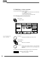
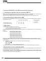
6. Sequences
Difference between
chaser and sequence
programs
Like a chaser a sequence contains a list of pictures stored as steps. The
additional features of the sequence give the chance to prepare complete light
shows and to recall them by the push of a button.
Individual step
parameters
- Unlike the chaser steps, every step of a sequence may have its individual
parameters. The time, until the next step starts (STEP TIME), the x-fade
time and the trigpoint may be different from step to step.
GO MODES
- The steps may be triggered via GO button, by SOUND INPUT, they may be
recalled by manual x-fade or on automatic mode with an internal timer and
preprogrammed or with an adjusted step time.
Overwriting during playback
- GO MODE, STEP TIME and FADE TIME of the single steps can be set
manually to overwrite the programmed parameters.
Linking steps to
memories or chaser
programs
- Standard chaser programs and memories can be recalled as one step of the
sequence.
- A sequence menu lists the actual and next steps
Programming and modifying a sequence works similar to the chaser programs.
6.1 Programming of sequences
Saving new steps works like saving new chaser steps.
6.1.1 New sequence steps
Programming sequence
steps
STORE button
Matrix can be set
(Prepare your stage plot like on programming memory)
SEQUENCE button 1 - 16
Selecting one of the 16 sequence buttons.
40
MA Lighting Technology GmbH . Dachdeckerstr. 16 . D-97297 Waldbüttelbrunn . Fax: + 49 9 31 4 97 94 29 . www.malighting.de
Scancommander
Programming of
sequence steps
INSERT
1.0
2.0
2.1
2.2
3.0
......
DELETE
ALL
SINGLE
PROGRAM SEQUENCE
STEP TIME
1.00 sec
LINK FADE
1
SEQUENCE:
STEPS:
FREE:
5
(94770)
NO NAME
STEP :
6
STEP FADE
0.00 sec
STEP TRIG
0%
3.5
Compared to programming a chaser step the following functions are
available:
Individual and freely
adjustable step numbers
Different GO MODES
ENCODER 2
Each step has its individual number from 0.0 up to
99.9. Like a name this number will stay with the step
during all copy and move operations.
Encoder wheel: first digits
Encoder ring: digits after the decimal point
STEP MODE buttons at the Sequence Playback
Sets the GO MODE for this step, which marks, how
the step will be recalled when running the sequence.
The selected mode is shown by the LED inside its
respective button and is displayed on top of encoder
1.
MAN FADE
Manual x-fade via the X-FADER in the sequence area.
GO BUTTON
The step has to be recalled by the GO button.
EXT SOUND
The step will wait for a sound impulse.
SET RATE
The step will be recalled automatically, as soon as
the STEP TIME of the last step runs out.
STEP TIME for timed step
following
STEP TIME and
ENCODER 3
Sets the time between this step and the start of the
next one, if the next one is on GO MODE "SET
RATE".
eMail: info@malighting.de . Tel.: + 49 9 31 49 79 40 . User's Manual Scancommander
41
All other functions work exactly the same way they do on chaser programming.
Deleting the old program
DELETE ALL
Clears all steps of the sequence.
Stop with the last step
SINGLE
Inverted:
Normal:
Selecting one step
The sequence will stop automatically when
reach ing the last step
The sequence will return to step one and will go on
running.
Encoder 1
Selecting a step number.
Setting the step parameters
STEP FADE or
STEP TRIG or
STEP TIME
Unlike on chaser steps, the step parameters will be
stored individually for every single sequence step.
ENCODER 3
Changing the value of the selected parameter.
In case LINK FADE is selected, the fade time is set
in percentage of the step time
Saving the step
INSERT
Shifts the selected step and all following steps one
step back and inserts the new stage scene at the
selected place.
STORE button
Overwrites the selected step by the new stage plot.
The total number of steps remains unchanged.
42
MA Lighting Technology GmbH . Dachdeckerstr. 16 . D-97297 Waldbüttelbrunn . Fax: + 49 9 31 4 97 94 29 . www.malighting.de
Scancommander
6.2 Playback of sequences
Starting a sequence
A sequence is started by its respective button like any other memory.
By any memory or chaser, recalled by its respective button after the start of
the sequence, the sequence may loose its priority. If the memory was a
selective one, some of the channels may still be available for the sequence, if
it was a standard memory with fully selected STORE MATRIX, the following
steps of the sequence will no longer have any effect on stage.
Red LED in the Step Mode
buttons
A red LED in one of the STEP MODE buttons indicates, how the next step has
to be recalled. The internally stored step mode is indicated by the green
LED´s, but has no effect as long as a red one is on.
Green LED in the Step
Mode buttons
Green LED´s: Only if none of the red LED´s is on, the next step is triggered by
the internally stored step mode.
GO buttons
GO+ and GO- buttons are always working, like the EXTERN GO input via
1/4" jack on the back panel does.
Set Time LED
SET TIME LED: if the LED is on, the x-fade time between the steps can be set
by the fader. The internally stored x-fade time of the steps has no effect.
6.2.1 Playback of a sequence by GO button
"GO BUTTON" Step Mode selected
Sequence via GO button
(red LED on)
SEQUENCE button 1-16
The LED in the button shows the selected sequence..
GO+ button
Recalls the first step of the sequence
GO+
GO+
Recalls the steps one by one.
GO- button
Recalls the previous step.
Note: When using standard memories, the GO- button will really recall the right stage picture. When
using selective programmed steps, recalling a step
via GO- may have another effect than recalling this
step via GO+.
eMail: info@malighting.de . Tel.: + 49 9 31 49 79 40 . User's Manual Scancommander
43
6.2.2 Playback of a sequence with adjusted step rate
Sequence playback with
adjusting rate via fader
RATE Fader
Sets the sequence speed between 0.1 and 10 seconds per step. The yellow LED inside the SET RATE
button shows the selected speed.
"SET RATE" Step Mode selected
(red LED on)
SEQUENCE button 1-16
The first step will be recalled as soon as the sequence button is pushed. All other steps will follow
automatically with the adjusted time.
6.2.3 Playback of a sequence triggered by sound input
On the backpanel the SCANCOMMANDER offers a 1/4"jack for sound signal
input. The 3 potentiometers on the top of the front panel can be used to select
a trigger signal. The HOLD LED shows the trigger signal leaving the filter as it
is triggering the sequence.
Triggering a sequence via
Sound input
SEQUENZ button 1-16
"EXT SOUND" Step Mode selected
(red LED on) The steps of the sequence is recalled
by the sound input.
6.2.4 Manual x-fade between sequence steps
X-FADER has to be moved to one of the end positions.
Manual x-fade step to step
(from version 1.40)
SEQUENZ button 1-16
"MAN FADE" Step Mode selected
(red LED on)
X-FADE fader at the sequence section
Moving the fader will fade between the steps. As
soon as the fader reaches the end of its travel, the
next step will be loaded for x-fade.
Moving back before the end of its travel is reached
will return the output to the last scene.
44
MA Lighting Technology GmbH . Dachdeckerstr. 16 . D-97297 Waldbüttelbrunn . Fax: + 49 9 31 4 97 94 29 . www.malighting.de
Scancommander
6.2.5 Playback of a sequence with programmed STEP MODE
Running a sequence with
internally stored STEP
MODE
STEP MODE buttons switched off
(All red LED´s off)
SEQUENZ button 1-16
Green LED´s indicating
internal STEP MODE
GREEN LED´s inside the SET MODE buttons
Show the step mode of the next step, as it was set
when programming the sequence. If one of the green
LED´s is on, the sequence waits for a trigger signal.
By the GO button the next step can be recalled any
time.
No green or red LED inside the SET RATE buttons
The next step will follow automatically as soon as the
STEP TIME of the last step runs out.
Note:
The yellow LED inside the SET RATE button will not
show the internally programmed STEP TIME, but will
always show the rate set by the fader.
6.2.6 Enable Sequence
Sequence recall without
going back to step 1
The ENABLE function like on Enable Chaser allows a sequence to resume
control of all channels without starting at step 1. A sequence, which has lost
access to some channels because of a direct access or memory recall, can
now continue as programmed.
ENABLE button.
Keep button pressed ...
... and simultaneously press ...
Sequence button of the actual sequence
The next step of the sequence is enabled to control
all channels according its step matrix.
eMail: info@malighting.de . Tel.: + 49 9 31 49 79 40 . User's Manual Scancommander
45
6.2.7 Sequence playback menu
Sequence playback menu
The MENU button at the sequence section swaps the display to list informations about the running sequence program.
MENU button
recalls the menu with number and name of the running
program at the top line. The total number of steps is
shown in brackets.
SEQ. 1
NAME
STEP
TIME FADE TRIG
(17)
02
2.0
5.075 Sec 0.0 00%
03
2.1
0.075 Sec 15 00%
04
3.0
12.00 Sec 1.5 50%
05
3.1
0.00 Sec 0.0 00%
NEXT
NAME / MATRIX
A/10
COLOR CHASER 1
GO
Line one lists the step which was recalled last. Line 2 to 4 show the next
steps. Each line shows step number, indicator of go mode, steptime, fadetime
and triggerpoint.
Right hand a small graphic shows the matrix of the steps (see 4.3),
indicating which channels get affected by this step.
If the step is a LINK MEMORY step, the number and name of the memory is
listed instead of the graphic.
Left side on the bottom line the go mode is shown on black background. If the
next step is a timed automatic, the remaining time is listed on the display.
The graphic right on the bottom line shows which channels are still
controlled by the Sequence. As soon as this graphic is empty and
white, all channels are overwritten by any memory or preset playbacks - the
sequence has no more effect on stage.
Changing step order by
jumping to another step
number
GO BUTTON Step Mode or
MAN FADE selected (red LED on)
Stops the running sequence. NEXT is displayed right on
top of the display.
NEXT button pressed and simultaneously
ENCODER 3
Via the encoder any step number can be selected to be
the next step on the sequence.
46
MA Lighting Technology GmbH . Dachdeckerstr. 16 . D-97297 Waldbüttelbrunn . Fax: + 49 9 31 4 97 94 29 . www.malighting.de
Scancommander
6.3 Modifying a sequence
All data of a sequence are data of single steps. They can be changed as soon
as these steps are selected. Global changes of speed or fade time, as it is
possible on the chaser programs, can be done by overwriting the stored values
via SET RATE and SET FADE.
6.3.1 Changing sequence step times
Changing step parameters
EDIT button
Sequence button 1-16
SINGLE
MODIFY
1.0
2.0
2.1
2.2
3.0
......
EDIT
SEQUENCE
1
SEQUENCE
STEPS:
FREE:
NAME
5
(94770)
STEP TIME
2.00 sec
LINK FADE
STEP FADE
1.00 sec
STEP TRIG
0%
4
SINGLE Mode
SINGLE
stops the sequence with the last step.
ENCODER 1
Selection of a step. The stored parameter of this step
are displayed and can be modified.
Selecting a parameter
STEP TIME or
STEP FADE or
STEP TRIG
Selection of one of the parameters.
Changing the value
ENCODER 2
Changing the value of the selected parameter.
In case LINK FADE is selected, the fade time is set
in percentage of the step time
eMail: info@malighting.de . Tel.: + 49 9 31 49 79 40 . User's Manual Scancommander
47
6.3.2 Changing step sequence and STEP MODES
EDIT button
Sequenz button 1-16
MODIFY
The selected step are recalled to stage and the
square MODIFY is displayed inverted.
MODIFY
MAKE
BLOCK
LINK
MEMORY
EDIT
MATRIX
1.0
2.0
2.1
2.2
3.0
EDIT
SEQUENCE
DELETE
STEP
DOUBLE
STEP
SEQUENCE:
STEPS:
FREE:
A 25
5
(94120)
RENAME
STEPS
NAME
STEP :
3
Testing the sequence
steps
2.1
Encoder 1
Scrolls through the list and recalls the steps to stage.
ENCODER 2
Changing the step numbers
Changes the step number. The ring is changing the
digits after the decimal point.
STEP MODE buttons in the sequence section
Changing the STEP
MODE
Change the STEP MODE of the selected step. The
green LED´s and the display show the selected mode.
DELETE STEP
Erasing a step
Clears the selected step and shifts all following steps
one step ahead.
DOUBLE STEP
Creating a new step
Makes a copy of the selected step and inserts this
copy right in front. The new step may now be modified or linked to a memory (>>6.3.4 Recalling a
memory or chaser as step of a sequence).
RENAME STEPS
Numbers all steps consecutively.
Clearing step numbers
48
MA Lighting Technology GmbH . Dachdeckerstr. 16 . D-97297 Waldbüttelbrunn . Fax: + 49 9 31 4 97 94 29 . www.malighting.de
Scancommander
Starting block operations
1. x MAKE BLOCK
Inverts the display square. The block operation mode
starts, where a complete set of steps can be handled
simultaneously.
Selecting steps
Encoder 1
Selects steps for the following block operations. The
numbers of the selected steps get inverted.
2. x MAKE BLOCK
The sections on top of the display show the different
block operations available.
MOVE
BLOCK
1.0
2.0
2.1
2.2
3.0
3.5
......
COPY
BLOCK
DELETE
BLOCK
CANCEL
BLOCK
EDIT
SEQUENCE
BLOCK
SEQUENCE:
STEPS: 6
FREE:
1
(94770)
START:
STEP 3
END:
STEP 5
INFO
7
Encoder 1
Selects a new step number.
Four different block
operations
MOVE BLOCK
Moves the sequence of steps, marked as block, to
the new address. The total number of steps remains
unchanged.
COPY BLOCK
Makes a copy of all the steps in the block and inserts
these steps at the new address
DELETE BLOCK
Deletes all steps marked as block and shifts the
following steps ahead.
Cancelling block mode
CANCEL BLOCK
Cancels the block operation mode and returns to the
modify menu.
eMail: info@malighting.de . Tel.: + 49 9 31 49 79 40 . User's Manual Scancommander
49
6.3.3 Changing step matrix and levels
EDIT button
Sequenz button 1-16
MODIFY
MODIFY
MAKE
BLOCK
LINK
MEMORY
EDIT
MATRIX
1.0
2.0
2.1
2.2
3.0
EDIT
SEQUENCE
DELETE
STEP
DOUBLE
STEP
SEQUENCE: A 25
STEPS: 5
(94120)
FREE:
RENAME
STEPS
NAME
STEP :
3
(
)
2.1
EDIT MATRIX
Edit Matrix has to be inverted, if the STORE MATRIX
will be checked or modified within the next steps.
Encoder 1
Testing single steps
Changing channel values
and the matrix of a step
Scrolls through the list of steps and recalls the steps
on stage.
Note: Scrolling backwards through a selective sequence with different STORE MATRIX selections from
step to step, will not produce the same stage scene
as scrolling forward.
Feature button
Scan Selection
Preset button or Encoder
Changing channel values via direct access.
1. x STORE button
If EDIT MATRIX was selected, it will show the STORE
MATRIX of this step.
2. x STORE button
Saves the modified step and returns to the modify
mode.
50
MA Lighting Technology GmbH . Dachdeckerstr. 16 . D-97297 Waldbüttelbrunn . Fax: + 49 9 31 4 97 94 29 . www.malighting.de
Scancommander
6.3.4 Recalling a memory or chaser as step of a sequence
Memories and chasers as
steps of a sequence
Memories and chasers of the playback section can be recalled as a step of a
sequence. This saves programming time and storage capacity.
EDIT button
Sequenz button 1-16
MODIFY
LINK MEMORY operation
MODIFY
MAKE
BLOCK
LINK
MEMORY
EDIT
MATRIX
1.0
2.0
2.1
2.2
3.0
EDIT
SEQUENCE
DELETE
STEP
DOUBLE
STEP
A/01
B/15
SEQUENCE:
STEPS:
FREE:
A 25
5
(94120)
RENAME
STEPS
NAME
STEP :
3
ENCODER 1
Selection of a step
number
Creating a new step
2.1
Selection of the step, the memory will be linked to.
(
)
DOUBLE STEP
Creates a new step which can be linked to the memory
without deleting any step.
Linking the step to the
memory section
LINK MEMORY
Selecting a memory or
chaser
MEMORY or CHASER button / PAGE A - D
Setting speed, fade time
and trigpoint
MODIFY switched off
ENCODER 2
Switching on: (block inverted)
Clears the channel values stored at this step and
links the step to a memory. Within the step list in the
display a memory number is shown for this step.
Switching off: (block no longer inverted)
Clears the link to the memory and leaves the step as
a blind step without any channels selected in its
matrix.
Selection of a memory by its playback button.
The speed of a linked chaser, the x-fade time and
trigpoint can be set by the encoders.
eMail: info@malighting.de . Tel.: + 49 9 31 49 79 40 . User's Manual Scancommander
51
7. REMOTE
The MA SCANCOMMANDER features several remote input facilities. The
different incoming signals can be linked to the playback functions of the board.
REMOTE button in the Top Menu
The display switches to the REMOTE Top Menu.
REMOTE Top Menu
MIDI
MIDI IN
ON/OFF
SMPTE
ON/OFF
TOUCHBOA.
ON/OFF
DMX
ON/OFF
TOUCHBOA.
MENU
DMX
MENU
SMPTE
MENU
NO EVENT
NO EVENT
NO EVENT
XXXXXXXXXXXXXXXX
NO EVENT
XXXXXXXXXXXXXXXXXXXXXXXX
Switching remote inputs
on and off
MIDI IN ON/OFF
SMPTE ON/OFF
TOUCHBOARD ON/OFF
DMX ON/OFF
An inverted block indicates, that the appropriate input
is activated. MIDI and SMPTE inputs can not be
active at the same time.
Indicating incoming
remote signals
NO EVENT
XXXXXXXXXXXXXXXX
With MIDI the last incoming signals will be listed in
the display. With DMX and Touchboard inputs, small
icons show the actual status of the input channels.
X
Input Channel is not connected to any function.
Input channel controls fader. Inverted icon
shows the value of the incoming signal.
Input channel controls button. Icon inverted
indicates button active.
Across the top of the REMOTE Menu are four buttons which activate the
remote initialization menus.
52
MA Lighting Technology GmbH . Dachdeckerstr. 16 . D-97297 Waldbüttelbrunn . Fax: + 49 9 31 4 97 94 29 . www.malighting.de
Scancommander
7.1 Remote via Touchboard
7.1.1 Input signal
Touchboard input
Located on the SCANCOMMANDERS backpanel is a 25 pin SUB-D connector
(female) which can be used to interface a standard 16 channel touchboard.
Pin 1-16 : Input channel 1 to 16
Pin 25:
Ground.
The touchboard can only be used to control on and off functions.
0 to +2 Volt : Off
+5 to +15 Volt : On.
7.1.2 Assigning board functions
REMOTE
TOUCHBOA. MENU
EDIT
List of input patches
DELETE
SINGLE
DELETE
ALL
1 MEM . A / 01
2 MEM . B / 15
3
4 MASTER A
5
6
7
8
EDIT
9
10
11
12
13
14
15
16
SELECT
Selection of an input
channel
Encoder 2
Linking the input to one of
the playback functions
Memory button or
Brightnessmaster flash button
Sequence button 1 - 16 or
GO button
Selecting one of the input channels 1 to 16 (block is
displayed inverted)
Links the selected function to this input channel.
QUIT button
Returns to the REMOTE top menu
Activating and terminating
the remote input
TOUCHBOARD ON/OFF
Switches the remote input on and off.
eMail: info@malighting.de . Tel.: + 49 9 31 49 79 40 . User's Manual Scancommander
53
7.2 Remote via DMX input
7.2.1 Input signal
Daisy chaining a DMX
signal
The male DMX 512 input XLR connector on the backpanel can be used to mix
the signals of any lighting console with the control data of the MA
SCANCOMMANDER and send them to the stage on one DMX line. For any
channel which is controlled from both consoles simultaneously, the two values
get compared and the highest level will be sent to stage.
Remote via DMX
In addition, up to 24 DMX 512 input channels can be used to remote control
single functions on the SCANCOMMANDER.
The pin layout for the DMX 512 input connector conforms with USITT protocol.
Pin 1 = Ground, Pin 2= Data - , Pin 3 = Data +
7.2.2 Assigning board functions
REMOTE button in the TOP MENU
DMX MENU
EDIT
List of input patches
DELETE
ALL
22
23
34
40
--
DELETE
SINGLE
MEM . A / 04
MEM . A / 05
MASTER A
MASTER B
SELECT
Selection of an input
channel
EDIT
-
--
DMX
23
Encoder 1
Selection of one of the 24 squares (inverted)
Encoder 3
Selection of a DMX input channel.
54
Linking to one of the
playback functions
Playback buttons (the same as on remote via touchboard)
Activating and terminating
the remote input
DMX ON/OFF at the Remote top menu
Links the selected function to the selected DMX
channel.
Switches the remote input on and off.
MA Lighting Technology GmbH . Dachdeckerstr. 16 . D-97297 Waldbüttelbrunn . Fax: + 49 9 31 4 97 94 29 . www.malighting.de
Scancommander
7.3 MIDI
MIDI Sequencer
The SCANCOMMANDER enables to record playback commands like recalling
memories, chasers, sequences and GO button pushes on to a MIDI sequencer.
During playback of the sequencer, the SCANCOMMANDER will receive these
commands as soon as the MIDI input is activated.
7.3.1 Choosing the MIDI channel
Selecting a MIDI channel
REMOTE at the Top Menu
MIDI
MIDI IN or MIDI OUT will be displayed inverted.
Encoder 1-3
Selection of one of the MIDI channels 1-16.
Activating and terminating
the remote input
MIDI Data
MIDI IN ON/OFF in the Remote top menu
Switching on and off the MIDI input. (MIDI output
works permanently.)
The Scancommander uses Control Change Data exclusively.
Commands:
The command 1011nnnn (Bn hex) (nnnn=MIDI channel) will always be sent as
status byte at first.
Again: "B" means Control Change, "nnnn" the MIDI Channel.
The following two bytes are the data bytes:
Command
1.2.Data byte______
push Memory button A1
: 00
+ 00
(Memory A1)
etc......
etc...
etc...
etc..
push Memory button A30
: 00
+ 29
(Memory A30)
push Memory button B1
: 00
+ 30
(Memory B1)
etc......
etc...
etc...
etc..
push Memory button B30
: 00
+ 59
(Memory B30)
push Memory button C1
: 01
+ 00
(Memory C1)
etc......
etc...
etc...
etc..
push Memory button C30
: 01
+ 29
(Memory C30)
push Memory button D1
: 01
+ 30
(Memory D1)
etc......
etc...
etc...
etc..
push Memory button B30
: 01
+ 59
(Memory D30)
push Sequence button 1
: 02
+ 00
(Sequence 1)
etc......
etc...
etc...
etc..
push Sequence button 16
: 02
+ 15
(Sequence 16)
push Go+ button
: 03
+ 00
(Go+)
push Go- button
: 03
+ 01
(Go-)
eMail: info@malighting.de . Tel.: + 49 9 31 49 79 40 . User's Manual Scancommander
55
7.4
Controlling more than 16
scans
Master-Slave Operation
When controlling more than 16 scans, two Scancommander or an additional
Extension unit (see 7.6) can be linked in a master-slave mode. All operations
are controlled via the master board, at the slave only the display and the single
scan selection buttons keep on working.
7.4.1 Installation
Installation for masterslave operation
MIDI OUT connector of the master has to be connected to
MIDI IN at the first slave unit.
More slaves can be added using the MIDI THRU port of the previous slave
The DMX output of all coupled units can be used as separate DMX lines.
Via the DMX input and by patching all scans to different DMX address
numbers, the control signals of more than one Scancommander can be send
on one DMX line.
7.4.2 Starting the couple mode
Activating the couple
mode at Remote MIDI
The first step is to prepare the slave units
REMOTE at the Top Menu
MIDI
MODE SLAVE has to be inverted
The last step is to set up the master board via REMOTE - MIDI - MODE
MASTER. If a SLAVE is used with a software version smaller than 4.20 it is
then really necessary to press the button "Mode: Old master".
The following RESET will send all necessary data from the master to all slave
units. If any slave comes later than the master, it will wait for a master reset
(lowest display button left side or switching off and on the master power
supply).
7.4.3 Working on master-slave mode
As far as the setups are not done before starting the couple mode, the first
steps will be SETUP LAMPTYPE, DMX and MOVEMENT.
Transfer of all functions to
the slave unit
All functions including trackerball movements, group selection and brightness
master are send from the master to the slave units.
Just the single scan selection button have to be operated at the according
units. To make sure that during DMX PATCH and MOVEMENT SETUP only
one scan is handled at a time, all other scans have to be deselected manually.
Instead of a second Scancommander, a 19" Scancommander Extension can
be used as slave (see 7.6).
56
MA Lighting Technology GmbH . Dachdeckerstr. 16 . D-97297 Waldbüttelbrunn . Fax: + 49 9 31 4 97 94 29 . www.malighting.de
Scancommander
7.5 SMPTE TIME CODE
SMPTE and EBU Time
Code
Complete shows can be synchronized via Time Code. The Scancommander
works with 24 to 30 frames per second. Selecting the right frame number will
be done automatically as soon as a Time Code signal is supplied or can be
selected manually.
7.5.1 Time Code Network Technics
Time Code synchronization
Time Code generation
Time Code synchronization can be used to recall the programs of one or more
controllers simultaneously to a recorded music.
SMPTE and EBU Time Code are digitally coded time informations, which for
example can be recorded to a separate track of a tape machine. The frequency
domain covers 1 to 2 kHz. Usually this Time Code will be recorded when
preparing the music for a presentation, but it can also be added afterwards by
any sound studio. When using stereo sound it is necessary to have at least a
third track on the machine, for preparing a Time Code show .
i.e.
Lasercontroller
Sound
Amplifier
Time Code
(Trac 3)
I.e.
Videocontroller
MA Scancommander
Sound signal
(Trac 1 and 2)
Synchronized
playback
Multitrac
tapemachine
During playback of the tape the Time Code signals are sent to all connected
controllers. Each device has stored in memory, which program has to be
recalled at which time.
The Time Code input at the Scancommander is on the 1/4" jack at the
backpanel.
eMail: info@malighting.de . Tel.: + 49 9 31 49 79 40 . User's Manual Scancommander
57
7.5.2 Live recording of a Time Code show
Recording a show
The RECORD mode enables to type in the program during running Time Code.
REMOTE at the Top Menu
SMPTE MENU
The display shows the SMPTE Menu with a list of the
programmed events.
SMPTE menu
MODIFY
FRAMES
30
ON
RECORD
DELETE
EVENT
INSERT
OVERWRITE
RECORD:
NEW
001
FINE
00:00:01:15
(000)
ON - OFF SMPTE
Parallel to the ON/OFF button in the Remote Top
menu this button will switch on and off the Time Code
input.
Select record mode
Start Time Code
RECORD
OVERWRITE mode and
RECORD : NEW selected (blocks inverted)
Tape playback start
The Scancommander shows the incoming time on the
display as
hours : minutes : second : frames.
Record events
Memory, Chaser, Sequence, Enable, GO+ and GORunning the show synchronously to the music, the
Scancommander lists all playback commands with
their exact time in the display.
NOTE: The brightness masters are not recorded. Fading
in and out the brightness on Time Code shows has to
be done by recalling appropriate memories or steps.
58
MA Lighting Technology GmbH . Dachdeckerstr. 16 . D-97297 Waldbüttelbrunn . Fax: + 49 9 31 4 97 94 29 . www.malighting.de
Scancommander
List of Time Code events
MODIFY
009
010
011
012
013
00
00
00
00
00
:
:
:
:
:
00
00
00
00
00
FRAMES
:
:
:
:
:
10
10
11
11
12
:
:
:
:
:
30
05
15
02
03
15
ON
MEM. A/02
MEM. A/03
SEQU. 01
GO +
MEM. B/02
RECORD
DELETE
EVENT
INSERT
OVERWRITE
RECORD:
NEW
FINE
00:00:12:23
(053)
Terminate record mode
RECORD
Switching off the button will terminate recording.
Beside recording a new show, the Scancommander offers different modes to
complete or replace parts of an already stored show. Three options can be
selected when recording (Time Code ON and RECORD selected) :
Insert additional events
INSERT
OVERWRITE
INSERT mode selected
Memory, Chaser, Sequenz, Enable, GO+ and GOThe already stored show is played back synchronously to the music and every new playback command, selected by its button, will
insert a new event.
Overwrite parts of a show
INSERT
OVERWRITE
RECORD:
NEW
OVERWRITE RECORD : NEW
mode selected
(like explained for recording a new show)
Memory, Chaser, Sequenz, Enable, GO+ and GOWithin the recorded period all old events are
erased. To keep parts of a show, RECORD has
to be switched off before the running Time Code
reaches this period.
Overwrite starting with the
first modification
INSERT
OVERWRITE
RECORD:
PRESET
OVERWRITE RECORD : PRESET
mode selected.
Memory, Chaser, Sequenz, Enable, GO+ and GOThe old show is played back and keeps unchanged. The first push of a playback button
starts the record mode and all following events
are erased until Record is switched off.
eMail: info@malighting.de . Tel.: + 49 9 31 49 79 40 . User's Manual Scancommander
59
7.5.3 Time Code Playback
Playback start via
taperecorder
Switch off RECORD mode
Tape machine
When starting a new playback of the tape, the Time
Code will be sent to the controllers again. As long as
the Time Code input is active, the Scan-commander
will recall the events as they are stored inside.
The Remote Top menu shows the incoming time and the last event. The
SMPTE menu shows the actual section of the event list.
Unreadable or missing
Time Code signal
NOTE !
Brightness gets controlled
by the master faders of
the desk
60
STOP
in the SMPTE menu
The input is waiting for a Time Code signal.
NOTE: Never record any event while STOP is displayed. The Scancommander now records more then
one event on the last frame and will clear the SMPTE
show because of illegal timing.
Master Fader
As the brightness masters are not recorded on Time
Code, they must be up during playback. Optionally
the SETUP function "MASTERS ALL 100%" can be
switched on.
Periodical playback
Playback of Time Code synchronized shows recommend no further operation
at the Scancommander. Every time the tape starts to send the Time Code, the
Scancommander will recall the programmed events. Even after switching off
and on the power supply, the Scancommander will stay in the Time Code
playback mode.
Overwriting a running
Time Code show
During a running Time Code show, all functions of the Scancommander stay
active and can be used for manually overwriting the program. Only a GO+ or
GO- command of the event list will have no effect, if the running sequence was
started manually. All other events will work as if the according playback
command was selected directly. To stop the Time Code show and go on
manually, the Time Code input has to be switched off. Returning to Time Code
any time will continue the show with the events, stored for this section.
Starting playback in the
middle of a show
A Time Code show can be started at any point of the tape. Using selective
memories or sequences this may cause changes in the effect on stage.
(GO commands do not recall well defined stage pictures, but do just trigger
the last selected sequence to go to the next step).
MA Lighting Technology GmbH . Dachdeckerstr. 16 . D-97297 Waldbüttelbrunn . Fax: + 49 9 31 4 97 94 29 . www.malighting.de
Scancommander
7.5.4 Modifying a Time Code program
Beside the Record mode, single events of a show can also be created or
modified step by step.
REMOTE
SMPTE MENU
The display shows the SMPTE menu with a list of the
programmed events.
Modify mode
MODIFY (block displayed inverted)
MODIFY
009
010
011
012
013
014
015
016
017
00
00
00
00
00
00
00
00
00
:
:
:
:
:
:
:
:
:
00
00
00
00
00
00
00
00
00
FRAMES
:
:
:
:
:
:
:
:
:
10
10
11
11
12
13
15
18
18
:
:
:
:
:
:
:
:
:
05
15
02
03
15
15
02
03
15
OFF
MEM. A/02
MEM. A/03
SEQU. 01
GO +
MEM. B/02
MEM. A/05
GO +
GO MEM. A/01
RECORD
DELETE
EVENT
INSERT
OVERWRITE
RECORD:
NEW
FINE
00:00:12:15
(053)
Selecting a single events
30
Encoder 1
Scrolls through the list of the programmed events.
Scrolling up will recall the events step by step.
Changing the event time
Encoder 2 and 3
Change the time of the selected event.
FINE
When FINE is selected, the encoder will change the
time in single frames or minutes, otherwise they will
do a course adjustment.
END OF RANGE
Display
The time of an event can only be selected
within the period of the last and the following event.
eMail: info@malighting.de . Tel.: + 49 9 31 49 79 40 . User's Manual Scancommander
61
Deleting a single event
DELETE EVENT
The selected event will be erased from the list.
Changing the playback
command of a single
event
INSERT
OVERWRITE
OVERWRITE mode selected:
Memory, Chaser, Sequenz, Enable, GO+ and GO- button:
The selected playback will substitute the old command.
Inserting a new event
INSERT
OVERWRITE
INSERT mode selected:
Memory, Chaser, Sequenz, Enable, GO+ and GO- button:
One frame before the selected event the playback
command will be inserted as a new event.
Error warning
INSERT NOT POSSIBLE
Display
There is no frame available to insert
a new event.
MAKE BLOCK operations:
Like on chaser or sequence modify, it is projected to
offer block operations also on the Time Code list.
This will be added within one of the next updates.
62
MA Lighting Technology GmbH . Dachdeckerstr. 16 . D-97297 Waldbüttelbrunn . Fax: + 49 9 31 4 97 94 29 . www.malighting.de
Scancommander
7.6 The Scancommander Extension Unit
The SCANCOMMANDER EXTENSION is a 19" unit with
- display with 12 display buttons and one encoder
- 16 scanselection buttons,
- cue card slot
- keyswitch
- all input and output connectors of a Scancommander
MASTER-SLAVE mode
Using the Extension as slave it will be switched to slave mode like a
Scancommander. As noted in 7.4 only the display and the single scan
selection buttons will work.
REMOTE operation (DMX, MIDI, Touchboard)
Programs can be set up at a Scancommander and transferred to the Extension via the cue card. The remote inputs can be used to recall the playbacks.
As the Extension unit has no brightness master faders, the SETUP function
"MASTERS ALL 100%" has to be switched on as long as the masters are not
remote controlled via DMX. All necessary steps to start the remote operation
can be done at the Extension unit directly.
STAND-ALONE operation (SMPTE Time Code)
For playback of SMPTE Time Code synchronised programs the Extension
can be used as a stand-alone unit.
(SETUP function "MASTERS ALL 100%" has to be switched on).
eMail: info@malighting.de . Tel.: + 49 9 31 49 79 40 . User's Manual Scancommander
63
8. Dimmer and color changers
Dimmer and color
changer
In addition to the channels for the 16 scanners, the MA SCANCOMMANDER
offers additional 96 channels to control dimmers, color changers or any other
DMX receiver. Like the features of the scans, these channels can be selected
via EXTRA 1 and EXTRA 2 and can be controlled via encoder or presets.
To include these EXTRA channels in any memory, chaser or sequence step,
they have to be selected in the STORE MATRIX when storing any scene.
8.1 Assigning EXTRA channels
Initialization by setting a
DMX address
Because the EXTRA channels control only simple functions, there is no need
for a major initialization process as with full function scanner. The units get
initialized as soon as a DMX address is registered in the SETUP DMX menu.
EXTRA 1 and EXTRA 2 can each address 16 units with up to 3 channels each.
The exact number of channels per unit is automatically adjusted according to
the free DMX channels following the selected address.
SETUP
DMX
EXTRA 1 or EXTRA 2
Selection of the unit
number
Selection of a DMX
address
Scan Selection
Any time, EXTRA 1 or EXTRA 2 are selected, the 16
buttons no longer represent the 16 scans, but the 16
units of the EXTRA 1 or 2 .
Encoder 1
Sets a DMX address.
PATCH
Number of channels per
unit
Each EXTRA unit may have up to 3 channels (number in brackets). The actual
number will be adjusted automatically according to the free DMX channels
following the selected address.
8.2 Direct access to EXTRA channels
EXTRA 1 and 2 on direct
access
EXTRA button inside the feature block must be on
The red labels under the feature buttons become
valid.
EXTRA 1 or EXTRA 2 button (red labels)
As with controlling scan features, the actual selection will determine, which of the channels get controlled simultaneously.
Encoder 1 to 3
Control the channels of the selected units.
64
MA Lighting Technology GmbH . Dachdeckerstr. 16 . D-97297 Waldbüttelbrunn . Fax: + 49 9 31 4 97 94 29 . www.malighting.de
Scancommander
8.3 EXTRA groups and brightness master
EXTRA 1 and EXTRA 2
groups
EXTRA 1 and EXTRA 2 have their own groups.
STORE
Keep button pressed and select one of the EXTRA
and simultaneously
GROUP buttons A - H
Stores a group for the EXTRA selection.
During EXTRA 1 or EXTRA 2 in DIRECT ACCESS the group buttons recall the
EXTRA groups instead of the scan groups.
When controlling color changer on EXTRA channels, this groups can be set to
be not under the control of the master faders. On dimmer channels EXTRA can
be set to be mastered by the fader.
SETUP
EXTRA controlled via the
brightness masters
The display buttons right hand side allow the following settings:
EXTRA 1
100 %
The values on display will be send to stage independent
from the master faders (color changer).
EXTRA 1
100 %
The values on display will be reduced according the
setting of the group faders.
8.4 EXTRA presets
EXTRA 1 and 2 Presets
As on any scan feature, for EXTRA 1 and EXTRA 2 presets can be programmed and used for quick and direct access.
PRESET in the top menu
EXTRA turned on
EXTRA 1 or EXTRA 2
The display shows the *ADJ.PRES* EXTRA x Menu
Controlling color changers via EXTRA becomes very easy by using the presets.
As with the color channel of the scans the different colours can be prepared
and labelled in their display blocks.
Even controlling dimmer channels via EXTRA is more handy when certain
values are stored as presets. For every EXTRA there are 4 pages offering 44
presets. As the value of the single channels may be different within a preset,
complete lighting cues can be stored as presets.
eMail: info@malighting.de . Tel.: + 49 9 31 49 79 40 . User's Manual Scancommander
65
8.5 EXTRA channels in memories
EXTRA 1 and 2 as part of
playback programs
EXTRA 1 and EXTRA 2 channels like any other scan feature can be selected in
the STORE MATRIX.
By using selective programming, it is possible to program memories or steps,
which control only the EXTRA channels, whereas other memories may control
only the scans and keep the dimmers and color changers untouched.
Programming the EXTRA
1 and 2 via a standard
lighting console
Instead of setting the values for EXTRA 1 or 2 via the encoder wheels or
presets, it is possible to set the values via a standard DMX console, connected
to the Scancommanders DMX input.
1. The DMX output of the lighting console goes to the DMX input of the
Scancommander, the Scancommander DMX output goes to stage.
2. EXTRA 1 or 2 units get patched to the same DMX addresses like the
lighting board channels. The Scancommander will compare the incoming
value and the Scancommander setting for the values and the highest will be
send to stage.
3.
EXTRA 1
DMX INPUT
4.
The DMX INPUT in the SETUP menu has to be
selected
STORE
Storing any memory or chaser step will take the DMX input values as set
at the lighting console and will store it within the Scancommanders memory.
The actual values at the Scancommander are ignored.
5. When modifying a picture via EDIT-MODIFY-STORE the Store will work as
regularly.
Playback of the
composed memories
!! ATTENTION !!
66
After programming the memories, the lighting console can be disconnected
and the memories can be recalled via the Scancommander.
To avoid clearing the EXTRA channel by any STORE operation, switch off
"EXTRA X DMX INPUT" as soon as the lighting console is disconnected.
MA Lighting Technology GmbH . Dachdeckerstr. 16 . D-97297 Waldbüttelbrunn . Fax: + 49 9 31 4 97 94 29 . www.malighting.de
Scancommander
9. Utilities
9.1 Display index
Active special functions are listed in the Top Menu.
Display index
Global modification of all
running fades
Indication of any fixed
channels
No index:
No special function active, trackerball switched off
MOUSE:SLOW
MOUSE:FAST
Trackerball working on high resolution
Trackerball working on low resolution
SINGLE
MIDI IN/OUT
Scanselection set to single scan mode (change via
OPTION button)
MIDI Remote active
MASTER
Console operates in master mode (see 7.4)
00:00:15
SMPTE TIME Code input active
RUNNING FADE
+/- 00%
In the Top Menu encoder number two can be used to
slow down or speed up all running fades simultaneously
FREEZE/FOLLOW Active
When recalling any memory, chase or sequence step, single channels may be
frozen via the FREEZE function or via MODE FOLLOW. Therefore the memory
can not be reproduced completely. This restriction is displayed by a short alert
showing "FREEZE/FOLLOW ACTIVE "(see 4.2.4 and 3.3.3)
eMail: info@malighting.de . Tel.: + 49 9 31 49 79 40 . User's Manual Scancommander
67
9.2 Storage of programs
Intern storage capacity of
the SCANCOMMANDER
The SCANCOMMANDER stores all programs internally. The number of scenes,
which fit the storage capacity, depend on the size of the single scenes.
- Memories controlling scans with 4 to 6 channels will need less space than
scans with 12 or more channels.
- Selective memories or steps only keep the data for the selected channels.
This way they also save space.
Therefore the exact number of scenes, possible to store internally, ranges
from 600 to more than 6000. The storage space still available is displayed by
FREE:(......) during any STORE operation. As soon as the limits are reached
(Display shows: NOT ENOUGH MEMORY), some of the unused programs
have to be cleared (see 9.3) or modified to selective programs.
9.2.1 Backup on to memory card
Backup on cue card
Beside the internal storage, programs can be stored externally on to cue card.
Storing on a cue card can be done in sections, for example only SETUP data
or only memory and chaser programs.
The SCANCOMMANDER will accept cue cards of the type ITT Star Card SRAM from 32 to 256 KByte, but as accessories it is recommended to use a
256 KByte card.
The card fits into the slot on the upper left side of the frontpanel, the arrow on
the card has to point to the left side.
BACKUP on the Top Menu
The SCANCOMMANDER changes to the backup menu
and tests the card.
WRITE : ENABLED - PROTECTED
A small switch on the card can be used to protect the
programs stored in the card.
FILES : ..... and FREE : (.......)
Number of files already saved on the card and freely
available storage capacity.
New cards have to be formatted after adjusting the battery.
Formatting the cue card
(only for new cards clears all data on card)
FORMAT
A name can be set for the card via the keyboard.
OK.
Formats the card, clears all data on the card and
prepares a file administration.
68
MA Lighting Technology GmbH . Dachdeckerstr. 16 . D-97297 Waldbüttelbrunn . Fax: + 49 9 31 4 97 94 29 . www.malighting.de
Scancommander
ALL
(86254)
PRESET
(16210)
MACROS
(512)
TEST 1
10.10.58
FORMAT
DELETE
MEMORY
(34556)
256 K
01 / 19 / 93
WRITE : ENABLED
FILES:
2
FREE:
(124233)
SAVE
Selecting a section for
backup operation
SEQUENCE
(512)
SMPTE
(512)
SETUP
(5120)
USER SCAN
1536
LOAD
ALL / PRESET / MEMORY / SEQUENCE /
SMPTE / SETUP
Selects the section to be stored or loaded. The
according block is displayed inverted.
Save data to card
SAVE
ENCODER 1
Scrolls through the list of files on card, available for
the selected data type. ("......" offers to create a new
file, to be named via keyboard.)
OK.
Saves the selected data section into the card with
name, time and date of storing.
Load data from card
LOAD - Encoder 1 - OK
Loads all data of the selected file into the boards
internal storage register and therefore overwrites the
data, already stored in the desk.
Deleting a file on card
DELETE
Encoder 1
Selection of one of the files on card
OK.
Deletes the file on card.
!! ATTENTION !!
The date of inserting a new battery should be noted on the cue card in order to
replaced it after 1 year. When exchanging the battery the card will keep its
memory for at least 30 second.
Please remove the card from the desk as long as the card is not in use!
eMail: info@malighting.de . Tel.: + 49 9 31 49 79 40 . User's Manual Scancommander
69
9.3 Clearing programs
CLEAR ALL
A CLEAR function allows to clear all programs within the Scancommanders
intern memory.
Keep all four buttons on top of the display pressed down when switching on
the Desk.
The Scancommander swaps to the CLEAR menu. Section by section the
programs can be deleted. Every clear has to be reconfirmed by "OK" or the
process can be stopped by "CANCEL".
By pressing the CLEAR ALL button all programs will be deleted simultaneously and all saved parameters will be reset to default values.
Clear single memory,
chase or step
Clearing a single memory is done by overwriting the old memory with a new
one with completely cleared STORE MATRIX.
STORE button
CLEAR button in the feature section
Clears the complete matrix.
Memory button
STORE button
Overwrites the old memory with a pseudo memory,
containing no data.
Deleting a single chase will be done by STORE - CHASER - DELETE ALL in
the program chase menu.
Deleting a single chase step can be done via EDIT - CHASER - MODIFY DELETE STEP.
9.4 Keyswitch
Protecting programs
The keyswitch right on top of the front panel allows to protect the programs
against unauthorized modification.
ACCESS ALL
All functions of the Scancommander are available
LOCK PRG
All playback functions are available, programming or
modifying pictures is not possible.
LOCK DESK
All buttons, encoders and faders on the front panel
are locked, but internally running programs go on.
Playback via any kind of remote input or master slave
communication keep on working.
70
MA Lighting Technology GmbH . Dachdeckerstr. 16 . D-97297 Waldbüttelbrunn . Fax: + 49 9 31 4 97 94 29 . www.malighting.de
Scancommander
9.5 Macros
The five macro buttons A to E right beside the cue card slot offer the possibility
to sample different key strokes to one single button.
9.5.1 Programming macros
Start of programming a
Macro
STORE
MACRO A
The display returns to the Top Menu, but a small
display "RECORDING MACRO X" marks that all
following functions are recorded.
All buttons but the single scan buttons
including the mouse buttons, get listed in the macro
ENCODER movements
get only listed within the BACKUP menu
End of programming a
macro
MACRO A
Selecting the macro button a second time closes the
list and stores the macro.
"RECORDING MACRO A" disappears
In case the maximum step number is reached (22-62 depending on the kind of
button), the macro is stored automatically with "MACRO FULL".
Macro playback
Playback of a macro:
MACRO A
Every time the macro button is used, the
Scancommander will repeat all listed operations.
Deleting a macro
!! ATTENTION !!
Macros can not be listed in the display. All special macros, including any
programming or deleting commands in their list, should be cleared as soon as
they have done their job.
Deleting a macro is done by
- STORE
- MACRO
- MACRO
eMail: info@malighting.de . Tel.: + 49 9 31 49 79 40 . User's Manual Scancommander
71
9.5.2 Macro user examples
Simplify the chase programming:
- STORE
- CHASER x
- STORE
must be stored as a macro.
Playback of a few memories (with delay):
The Scancommander can store up to 50 button instructions.
If a macro recalls
- 20 x Memory A/1,
- 10 x A/2 and then
- A/3 ,
so will be first done A/1, after 0.4 second delay A/2 and after
0.2 second A/3 . Longer delays can be realized by programming
chases or sequences.
Exchange of all memories:
A macro is stored :
- BACKUP
- MEMORY
- LOAD
- Encoder on file list start
- Encoder on file
- OK
- QUIT
a second macro loads an other memory file.
With these two macros a complete set of new memories can be loaded
very fast.
Start of a follow action with the actual scan selection:
With the macro
- Pan/Tilt
- Preset "Vocal "
- EXTRA
- FOLLOW
- FREEZE FOLLOW
the actual scan selection can be set to position "Vocal" and at the same time
fixed on the trackerball.
72
MA Lighting Technology GmbH . Dachdeckerstr. 16 . D-97297 Waldbüttelbrunn . Fax: + 49 9 31 4 97 94 29 . www.malighting.de
Scancommander
10. Inputs and outputs
Mains (Power Supply)
The Scancommander can be connected to an AC Powersource between 90
and 240 Volt AC (40-60Hz).
The powerswitch is located on the front panel at the top right hand side.
DMX 512 output
The DMX output conforms to USITT DMX 1990. Every unit using this protocol
can be successfully interfaced with the Scancommander.
The DMX Output is optically isolated and exceeds the RS485 Norm.
Pinout: pin 1 = Shield
pin 2 = Data pin 3 = Data +
pin 4 = not connected
pin 5 = not connected
DMX 512 input
Sound input
The DMX Input allows operation of two different functions:
a. All incoming DMX-Data will be merged with the Data produced by the
Scancommander. The highest value takes precedence at the DMX output.
b. To remote various functions of the Scancommander via DMX, e.g. coupling
a lightning desk and a Scancommander. For configuration see “Remote”.
The connector is a Mono or Stereo Phone Jack 6,3mm and the input is
galvanic insulated. Input impedance is ca. 3K Ohm, the threshold is min. 3
mV. The electrical connection is tip and sleeve. The Sound Input controls are
located on the upper left side of the front panel.
Adjustment: Turn the volume control until the left LED begins to light; higher
inputs are limited automatically. To get the best results, the frequency
control should be turned to the left for low frequencies (50 Hz), to the right
for high frequencies (2 kHz). ”Hold-Off” control should be initially set full
left.
To avoid double triggering of a bass drum for example, rotate “Hold Off” as
needed. At full right, “Hold Off” time is a full six seconds.
SMPTE Time Code
Remote GO input
The Sound Input doubles as the Time Code Input.
The electrical connection is the ring + common (galvanic insulated). The input
impedance is ca. 3 kOhm, the minimal level ca.200mV.
The Remote Go input is a 6.3 mm Phone Jack connector.
a) For electrical contact-switch use the ring and tip.
b) For 5 Volt Impulse use the tip and common.
Danger! Maximum 5 Volt at this input; a higher voltage may damage the
Scancommander.
The connection is a 25 pin Sub-D.
eMail: info@malighting.de . Tel.: + 49 9 31 49 79 40 . User's Manual Scancommander
73
74
Touch board input
This input is used to control 16 different functions (similar to the DMX-Input).
For the configuration see “Remote”.
Pinout:
pin 1 = function 1
pin 2 = function 2
etc....
pin 25= common
The threshold level is between 4V and 10V. Input impedance is 100 kOhm.
Trackball or mouse
Necessary to work comfortably in the Follow Mode and to set the Pan/Tilt
position.
The trackerball connector is compatible with the ATARI norm. PC compatible
trackerballs will not work with the Scancommander.
Keyboard
Necessary to enter the names of the Memories etc. The connector is a 5pin
Din. Every PC compatible AT/MF-keyboard can be used.
ATTENTION!!
All DMX512 and analogue inputs and outputs must be shielded and the shielding
must be connected to the ground and the case of the corresponding plug.
MA Lighting Technology GmbH . Dachdeckerstr. 16 . D-97297 Waldbüttelbrunn . Fax: + 49 9 31 4 97 94 29 . www.malighting.de
Scancommander
11. Defining your own Scans
Starting with software version 4.x the Scancommander now offers the possibility to define your own lamptypes. These lamptypes can be then used like
any other default lamptype in the LAMPTYPE SETUP.
This new feature enables the adaptation of the software to new scantypes
which are not listed in the factory setup or lamptypes which has changed
their channel order. All characteristics (e.g. name, type, channel order of
DMX control and brightness master functions) can be programmed for up to
16 free definable types.
SETUP
MAKE LAMPTYPE
NAME
SHORT NAME
SCANTYPE
CHANNELS
BRIGHTNESS
BLACKOUT
FIXED CH1
FIXED CH2
FREEPATCH
C-M-Y MODE
:
:
:
:
:
:
:
:
:
:
USER 1
Encoder 1:
Selects the number of
the free definable scan
between 1 and 16.
Attention: This number
does not correlate with
fixture number 1 to 16
which has to be assigned
later. So the lamptype
"USER 1" can be used
for all 16 lamps in the
LAMPTYPE SETUP.
`MY_SCAN1 1 XYZ 199 ´
`MS1 ´
MIRROR
17
DIMMER NORMAL
---- , < 2%
---- , 0%
---- , 0%
0%
NORMAL
EDIT
4
BRIGHTNESS
Encoder 2:
Selects the line
to be edit.
eMail: info@malighting.de . Tel.: + 49 9 31 49 79 40 . User's Manual Scancommander
Encoder 3:
Selects some parts of
adjustments. If the
adjustments are more
complex, the EDIT
button will lead to further menus.
75
Explanation of the different
parameters
NAME
SHORT NAME
:
:
`MY_SCAN1 1 XYZ 199 ´
`MS1 ´
The name of the lamptype (19 characters) and the
shortname (6 characters) can be entered by the keyboard
Mirror or headlamp
SCANTYPE
:
MIRROR
Selection of MIRROR or HEAD (e.g. Vary* lites). This
function is only valid for the stage movements.
Channel order
CHANNELS
:
EDIT
17
leads to the menu for the channel order:
CH. 1
CH. 2
CH. 3
CH. 4
CH. 5
CH. 6
CH. 7
CH. 8
CH. 9
CH.10
CH.11
CH.12
:
:
:
:
:
:
:
:
:
:
:
:
GOBO2
TILT
GOBO1
COLOR1
DIMMER
PRISMA
CYAN
YELLOW
COLOR2
GO1-ROT
MAGENTA
FOCUS
CH.13
CH.14
CH.15
CH.16
CH.17
CH.18
CH.18
CH.20
CH.21
CH.22
CH.23
CH.24
:
:
:
:
:
:
:
:
:
:
:
:
PAN
IRIS
SPEED1
FROST
SHUTTER
----------------------
CHAN. 1
USER 1
CLEAR
RETURN
GOBO 2
ENCODER 2 and 3:
Selection of the DMX channel (inverse) and the corresponding function. These channels must be selected and
set up one by one.
24 channels can be programmed to the functions of the
Scancommander. These functions can be selected by
encoder 3 in the following order:
Gobo 1
Gobo 2
Color 1
Color 2
Dimmer
Cyan
Magenta
Yellow
Prism
Iris
Focus
Frost
76
Zoom
Shutter
Speed 1
Speed 2
Special
Gobo1-Rotation
Gobo2-Rotation
Prism Rotation
Pan
Pan fine
Tilt
Tilt fine
MA Lighting Technology GmbH . Dachdeckerstr. 16 . D-97297 Waldbüttelbrunn . Fax: + 49 9 31 4 97 94 29 . www.malighting.de
Scancommander
CLEAR
Deletes all settings starting with the selected channel for
this user type.
RETURN
Leads back to the MAKE LAMPTYPE menu.
Assignment of the brightness
master
BRIGHTNESS
:
DIMMER NORMAL
The brightness of different groups can be controlled via the Scancommander´s
brightness master. The channels that are affected by the brightness masters, are programmed in the BRIGHTNESS and BLACKOUT menu.
EDIT
leads to the menu defining the brightness master
BRIGHTNESS:
CHANNEL
MODE
:
:
USER 1
DIMMER
NORMAL
4
CHANNEL
RETURN
DIMMER
ENCODER 2 and 3:
Select the line and function
CHANNEL: Here the channel can be selected to be
dimmed by the brightness master (normally dimmer).
MODE: NORMAL resp. INVERS
INVERS must be selected if the scan for level=00
is 100 % on.
BLACKOUT
:
SHUTTER, < 5%
Corresponding to the BRIGHTNESS menu a channel can
be selected which will be set to 0 if a specific threshold
(e.g. 5%) is reached.
eMail: info@malighting.de . Tel.: + 49 9 31 49 79 40 . User's Manual Scancommander
77
Special functions
Fixed channels
FIXED CH1
FIXED CH2
:
:
---- ,
---- ,
0%
0%
This functions enables you to set two channels to a fixed
level. This channel must be connected first to an unused
function of the Scancommander. Than it can be fixed in
the FIXED CH1 resp. FIXED CH2 menu to a specific level.
Later this channel will not be affected by any function of
the Scancommander.
!
Free patch of one of the scan
functions
FREEPATCH
(For example: The (Lightwave research) Studiocolor needs
channel 16 to be set at 00).
: ----The last function of the filed channel list can be separated optionally from the other DMX channels of the scan.
Later this function can be patched separately. Therefore it
must be selected by the third encoder.
(Example: In the VL5 of Vari*Lite the dimmer is separated
from the other control channels and is controlled by an
external dimmer. By the FREEPATCH function this dimmer address can be entered separately)
If a lamp was defined in the FREEPATCH menu it will
appear in the LAMPTYPE SETUP menu as follows:
SCAN
DIMMER
Adaptation of the colour mix
function
C-M-Y MODE
:
- button
here the lamp can be selected and patched
separately
NORMAL (optionally INVERS)
Up to now the scan manufacturers do not agree to an
uniform colour mix. Some work with C-M-Y, others with
the R-G-B colour mix. To reach a better control of the
colour mix function the C-M-Y function can be inverted.
78
MA Lighting Technology GmbH . Dachdeckerstr. 16 . D-97297 Waldbüttelbrunn . Fax: + 49 9 31 4 97 94 29 . www.malighting.de
Scancommander
00:00:15 67
16 BIT accuracy 23
C-M-Y Mode 78
Computermouse 6
Controlling color changers 65
Controlling dimmer channels 65
COPY BLOCK 38, 49
Copying memories 32
Cue card 6
A
D
ACCESS ALL 70
Adaptation to new stage setups 18
Adjusting preset positions 20
ALL 69
Atari compatible mouse or trackball 6, 21
Daisy chaining a DMX signal 54
DELETE ALL 33, 42
DELETE BLOCK 38, 49
DELETE EVENT 62
DELETE STEP 37, 48
Deleting a chase 70
Deleting a file on card 69
Deleting a macro 71
Dimmer and color changers 9, 64
Direct access 13
Display buttons 7
DMX 512 9, 64
DMX 512 input 66, 73
DMX 512 output 6, 73
DMX interface 9
DMX MOVEMENT 10
DMX output addresses 9
DMX REMOTE ON/OFF 52
DOUBLE STEP 37, 48, 51
Drawback of selective programming 30
Drawer 6
Index
Symbole
B
Backup on cue card 6, 68
Blackout
77
Block operations 37, 49
Board housing 6
Brightness fader 13
brightness master on EXTRA
65
C
CANCEL 70
CANCEL BLOCK 38, 49
CHANGE PAN<>TILT 10, 11
Changing chaser name and parameters 36
Changing chaser step matrix and levels 39
Changing memory matrix and data 31
Changing memory parameters 31
Changing order of chaser steps 37
Changing sequence step matrix and levels 50
Changing sequence STEP MODE 48
Changing sequence step numbers 48
Changing sequence step order 48
Changing sequence step times 47
Changing the event time 61
Channels per EXTRA unit 64
Chaser 33
CHASER SPEED 34
Circle mode 22
CIRCLE OFF 22, 30
Circle speed 22
CLEAR (DMX output patch) 9
CLEAR (Scanselection) 13
CLEAR (STORE MATRIX) 24
CLEAR ALL 70
CLEAR FREEZE 27
"CLEAR"-"INVERT" 13
Clearing a memory 70
Clearing programs 70
E
EBU Time Code 57
EDIT 31, 32, 36, 37, 39, 47, 50, 53, 54
EDIT MATRIX 31, 39
Enable Chaser 35
Enable Sequenz 45
Encoder ring 14
Encoders 7, 14
END OF RANGE 61
Events 58, 59
EXT SOUND 41, 44
Extension Unit 56, 63
EXTERN GO 43
EXTRA 1 100 % 65
EXTRA 1 DMX INPUT 66
EXTRA 1 and 2 groups 65
EXTRA 1 and 2 in memories 66
EXTRA 1 and 2 on direct access 64
EXTRA 1 and 2 Presets 65
EXTRA channels 64
Extra1,Extra2 9
eMail: info@malighting.de . Tel.: + 49 9 31 49 79 40 . User's Manual Scancommander
79
F
FADE LED flashes 26
FADE MODE 26
FADE TIME 40
FEATURE button 14, 15
FILES 68
FINE 61
Fixing the followspot mode 21
Follow mode 11, 18, 21
Followspot in standard operation mode 21
FORMAT 68
frame number 57
FRAMES 59
FREE 68
Freepatch 78
FREEZE 27, 35
FREEZE FOLLOW 21, 27
FREEZE/FOLLOW ACTIV 67
Freezing single channels 35
G
GO BUTTON 40, 41, 43
GO MODES 40, 41
graphic on sequence menu 46
Green LED´s in the SET MODE 43, 45
Group button A-H 13, 65
I
INIT:SCANS+VALUES+NAMES 8
Initialization of stage 11
Inputs and outputs 73
INSERT 34, 42
Insert additional events 59
INSERT mode 59, 62
INSERT NOT POSSIBLE 62
Inserting a new event 62
INVERT (Scanselection) 13
INVERT PAN 10, 11
INVERT TILT 10, 11
J
jumping to another step number 46
K
KEYBOARD 6, 15, 25, 74
Keyboard drawer 6
Keyswitch 70
L
Lamp Type Menu 8
LAMPTYPE 8
80
LINK FADE 34, 36, 42, 47
LINK MEMORY 46, 51
LIST 28
Load data from card 69
LOCK DESK 70
LOCK PRG 70
M
Macro user examples 72
Macros 71
Mains (Power Supply) 73
MAKE BLOCK 37, 38, 49
MAN FADE 26
Manual x-fade memory 26
Manual x-fade sequence step 44
Manufacturer 8
MASTER 67
MASTER-SLAVE 56, 63
Master-Slave operation via MIDI 55
Masterfaders 13
MASTERS ALL 100% 13, 60, 63
Memories 24
Memories and chasers as steps of a sequence 51
Memory name 25, 28
Memory pages 25
MENU 46
MIDI 55
MIDI FORMAT 55
MIDI IN ON/OFF 52, 55
MIDI IN/OUT 67
MIDI sequencer 55, 56
MODE MASTER 56
MODE PROGRAM 21
MODE SLAVE 56
modification of running fades 67
MODIFY 31, 37, 39, 48, 50, 58, 61
Modifying a chaser program 36
Modifying a sequence 47
Modifying a Time Code program 61
Modifying of memories 31
Modifying PRESETS 15
MORE 1(3) 8
Mouse button 21
MOUSE:SLOW 67
MOVE BLOCK 38, 49
Movement control 11
Movement initialization 20
movement mode change 19
Movement on direct DMX 18
Movement on stage calculation 18
Movement speed 23
MULTI 13
MA Lighting Technology GmbH . Dachdeckerstr. 16 . D-97297 Waldbüttelbrunn . Fax: + 49 9 31 4 97 94 29 . www.malighting.de
Scancommander
N
R
New stage setup 20
NEXT in the sequence menu
NO EVENT 52
Number in brackets 9
46
O
OK 68
OPTION 13, 19
Outside the stage 21
Overwrite an old step 34
OVERWRITE mode 58, 59, 62
Overwrite parts of a show 59
Overwriting a running chaser 35
Overwriting the programmed fade time
26
P
PAGE A-D 25
PAN/TILT via encoder and Presets 18
PAN/TILT coordinates 18
PATCH 9, 64
PC compatible mice 6
PC-MF keyboard 6
Percentage 34, 36, 42, 47
PLAYBACK area 25
Playback chasers 35
Playback memories 26
Playback of presets 16
Playback of selective memories 30
Playback of sequences 43
Powersupply 6
PRESET ADJUST 15
PRESET names 15
Preset X-Fades 16
PRESETS 15
PRESETS for Pan/Tilt 19
Priority 35
Programming chaser parameters 34
Programming macros 71
Programming of basic memories 24
Programming of chasers 33
Programming of presets 15
Programming of scan groups 13
Programming of selective memories 29
Programming of sequences 40
Q
QUIT 7
Radius 22
RATE Fader 44
READY 8
RECORD 58
RECORD : NEW 58, 59
RECORD : PRESET 59
Red LED´s in SET MODE 43
Red printed functions 14
Registration card 5
Registration of selected lamp type 8
REMOTE 52, 55, 58
Remote GO input 73
REMOTE Top Menu 52
Remote via DMX input 54
Remote via Touchboard 53
RENAME STEPS 48
RESET 10, 11, 56
rhomb in front of Pan/Tilt values 18
RUNNING FADE 7, 67
S
S1 to S10 25
SAMPLE CLEAR 17
SAMPLE display 17
SAMPLE function 17
SAMPLE GO 17
Save data to card 69
Scan groups 13
SCAN SELECTION 13, 14
Scancommander Extension 63
SCANS 9
Selecting a single event 61
Selective memories 24, 29, 35
SEQUENCE 69
sequence playback menu 40, 46
Sequence playback rate via fader 44
Sequence via GO button 43
sequence via Sound input 44
sequence with intern stored STEP MODE 45
Sequences 40
SET RATE 41, 44
SET SELECTION TO DMX 19
SET SELECTION TO STAGE 19
SET TIME 26
Set Time LED 43
SET- corner button 12
SETUP 7, 8, 9, 11, 64, 69
Shutter Strobe Off 30
SINGLE 13, 33, 42, 67
Slow/Fast 21
eMail: info@malighting.de . Tel.: + 49 9 31 49 79 40 . User's Manual Scancommander
81
Smooth movement 23
SMPTE 69
SMPTE MENU 58
SMPTE ON/OFF 52
SMPTE Time Code 73
SMPTE Tme Code 57
SOUND INPUT 40, 73
Speed channel 23
Stage 19
Stage corners 12
Standart Memories 26
Start a chaser 35
Starting a sequence 43
Starting angle 22
STEP FADE 34, 36, 42, 47
STEP MODE 43, 48
Step numbers 41
STEP TIME 40, 41, 42, 47
STEP TRIG 34, 36, 42, 47
STOP 60
Stop a running chaser 35
Storage capacity 30, 68
Storage of programs 68
STORE 12, 13, 15, 24, 29, 33, 34, 39, 42, 50, 71
STORE MATRIX 24, 29, 31, 66
Synchronisation 57
Synchronized playback 57
V
VL5
78
W
WRITE : ENABLED - PROTECTED
68
X
x-fade 25
x-fader in the playback section
x-fades to a preset 16
X/Y coordinates 11
26
Y
Yellow LED in the SET RATE 45
T
Tape playback 58
Terminate record mode 59
Termination of a chaser 35
Testing single steps 50
TIME CODE 57
Time Code 57
Time Code generation 57
Time Code Playback 60
Top menu 7
Touch board 74
TOUCHBOA. MENU 53
Touchboard input 53
TOUCHBOARD ON/OFF 52, 53
Trackball or mouse 19, 21, 74
Tracking of a person 21
Trigpoint and x-fade 25
U
USITT DMX 512 6
Utilities 67
82
MA Lighting Technology GmbH . Dachdeckerstr. 16 . D-97297 Waldbüttelbrunn . Fax: + 49 9 31 4 97 94 29 . www.malighting.de
Scancommander
Fixture Library SC 4.31
Manufacturer
Fixture Name
OPEN
No Scan
ABSTRACT
Futurescan
4
ADB (BBA)
Ingenio BBA LR
6
AMPTOWN
ACC Posi Spot
Contr.PML MK2
Contr.WL HX
Contr.WL HP
4
12
7
10
B+K
Varytec
5
CAMELEON
Telescan MARK I
Telescan MARK IV
8
19
CLAY PAKY
Miniscan 300
Miniscan HPE
Goldenscan2
Goldenscan3
Goldenscan3
Goldenscan HPE
Superscan
Superscan MRG
Superscan Zoom
Superscan Zoom
Stage Scan
Stage Light 300
Stage Color 300
Stage Color 575
Stage Color 1000
Stage Color 1200
Stage Color SV 1200
Golden Spot
Golden Color 1200
Stage Zoom
Stage Zoom SV 1200
Shadow
Tigerscan
Pinscan
Bazuka
Polycolor
Tiger MRG
Tiger COLOUR Changer
Combicolor
4
7
6
6
8
12
12
12
12
16
17
10
10
14
11
14
14
13
10
19
20
4
6
3
6
6
4
3
4
Performance 200
Performance1-3
Performance3
Performance4
Coef 1200 Disco
Color Show 200
MP 250 Optic HR+
MP 250 FRESNEL HR+
6
6
9
10
8
5
9
9
COEMAR
Microscan 1/2 400/650
Microscan 3
Samurai
MINI ULTRA 200/250
MINI ULTRA 2
NAT MM 1200 DX
NAT MM 1200 PR
NAT MM 1200 ZOOM
MM 2500 Zoom
Nat TM 1200 DX
Nat TM 1200 DXP
Nat TM 1200/4000
Nat TM 2500
CF 1200 Hard Edge
CF 1200 Spot
PC 1000 CC
Duetto
Pchmi
CF7 Zoom Wash
CF7 Hard Edge
6
8
8
6
8
10
13
20
20
12
14
20
21
20
13
8
6
9
13
20
DAH
Digital Beamlight
10
COEF
No. of Channels
No Scan connected
Color changer
Brightness Master optional fading or switching Gobo
Brightness Master optional on Iris or Shutter
Followspot only
Color changer
Color changer
Color changer
eMail: info@malighting.de . Tel.: + 49 9 31 49 79 40 . User's Manual Scancommander
83
Manufacturer
Fixture Name
EASYLIGHT
Twist HTI 300 DMX
Easylight Scan 3
Easylight Scan 3D2
Easylight Rainbow
Easylight Colore LC
Easylight Colore 2
4
6
7
2
2
4
FAL
FAL 2000
FAL 2500 XL/XLD
FAL 2500 XLDX
Roulette 575/1200
Proscan II HR
Proscan X HR
Promo 2/3
Three-Sixty
Three-Sixty2
7
11
14
8
14
13
6
8
10
FLY
FOS 3 / 4
Palette
12
5
FUTURE-LIGHT
Miracle
CC-200
SC-330/370
Promotion Scan HR
Genesis
Voyager
Duke 1200
Advert Scan HR
SC-250
SC-530/570
SC-740
SC-780
SC-940/980
MH-640
MH 660 Spot
MH-840
MH 860 Spot
4
4
4
11
8
8
8
11
6
10
13
16
16
16
16
16
16
GENIUS
Omega2
10
GLP
Mini Star Tec
Mighty Scan
MAX
Startec 2000
Startec 1200
Joy 300
Patend 575 PAN_coars
Patend 575 PAN_FINE
Patend 1200
6
6
8
7/9
12
11
13
13
17
GRIVEN
Cruise
11
HIGH END
Trackspot
Technobeam HR
Technobeam Iris HR
Intellabeam
Intellabeam HR
Cyberlight CX Mode3
Cyberlight Mode2 20
Studiocolor
Studiocolor 250
Studio Spot 575
Studio Spot CMY
Studio Beam PC V1.0
Studio Spot 250
Technopro HR
Trackspot mainlight
Technoray hR
Dataflash
7
18
18
8
13
15
20
16
15
24
24
16
18
12
5
14
3
Varyscan 1
Varyscan 3 SP+
Varyscan 3 SP+
Varyscan 3 700
Varyscan 4
Varyscan 4 EV
Varyscan 5 MV
Varyscan 6 spot
Varycolor 6 wash
Varycolor
4
6
8
13
8
11
22
12
12
6
J.B.
84
No. of Channels
Followspot
(NO MOVEMENT)
MA Lighting Technology GmbH . Dachdeckerstr. 16 . D-97297 Waldbüttelbrunn . Fax: + 49 9 31 4 97 94 29 . www.malighting.de
Scancommander
Manufacturer
Fixture Name
LAMPO
Sintesi+Super
Columbus 1200 AF
6
10
LICHTTECHNIK
Motor Yoke 300,330
17
LITEBEAM
Swing I
Swing II
Chandra I
Chandra II
Swing II HR
Chandra II HR
6
12
7
12
14
14
LYTE QUEST
MotorHead
5
MAD LIGHTING
Qscan
Scan611
5
6
MARTIN
Roboscan 804/805
Roboscan 218
Roboscan 218 m3 HR
Roboscan 518
Roboscan 518 m3 HR
Roboscan 812
Robo 918 m4
Robo 1020
Robo 1220
Imagescan m2
Robo 1220 rpr m4
Pal FX 1200 m4
Mac2000Profile
Mac 1200 m4
Mac 600 m4
Mac 600 NT m4
Mac 500 m4
Mac 300 m4
Mac 250 m4
MiniMac Pr m4
MiniMac WS m4
MX-1
Robocolor / MSD EX
Robocolor pro4
Robozap
Robozap MSR
Centerpiece H3+4=GO
5
7
9
9
9
7
16
12
16
9
17
20
24
14
14
15
16
13
13
10
8
6
5/6/7
5
4
6
7
MORPHEUS
PANa Beam
Coloure Fader Dimmer
4
4
MOVITEC
SL-250
WL-250
SL-575
WL-575
16
16
16
16
OBIES
Xescan
10
OMICRON
Omicron Laser
16
OPTIKINETICS
Solar System
7
SAGITTER
Prince
Super Prince
Infinity HR
Infinity MSZ HR
Infinity Club
Infinity Live
Tracer
Mask Color Zoom
Moving Spot 250 / 575
Moving Wash 250 / 575
6
10
12
14
12
20
5
10
16
16
Galileo 1
Galileo 2 HR
Galileo 3 HR
Galileo 4 HR
Giotto
Victory1
Victory2
Giotto Spot 250/400
Giotto Wash 1200
Giotto Spot 1200
Giotto 1200 Doors
6
12
14
18
13
9
12
22
13
18
18
S G M
No. of Channels
Mode 4 only, with 6 or 8 EXTRA channels
Color changer, Optional 5 or 7 channel
PRINCE and SUPER PRINCE TEMPLATE
Followspot
eMail: info@malighting.de . Tel.: + 49 9 31 49 79 40 . User's Manual Scancommander
85
Manufacturer
Fixture Name
SHOWPRO
Cyberscan HR
Accubeam AB-400
Accucolor
10/13
4
2/3
SLS
Panscan 3 Junior
Panscan4 HR
5
15
SPACE CANNON
Target + Devil
8
STARLITE
Starlite 2G HR
Starlite Mk5
9
19
STRONG
Mini Scan Rotax
Big Scan 3
6
12
STUDIO DUE
Varybeam
CityColor
Live Pro 1200 CMY
Live Pro 1200 PRISM
Live Pro 1200 FROST
Stratos HR
Stratos CMY R.Gobo
Stratos CMY Iris
Minibeam
Giant HR
Light Reflector
Predator
Carioca
Stratos HR Dim neg
Stratos LR Dim neg
7
7
20
16
16
15
15
15
6
9
7
6
5
14
12
SUMMA USA
Summa hti
9
TAS
Crono
CF6
9
12
THEATRE
86
PROJECTS Sky Art
PAL (PPTTFC)
No. of Channels
7
6
VARI*LITE
VL1
Vlm m3
Vlm m4 Ex
Vl5/Vl5B m3
Vl5 m4 16B Ex
Vl5 Arc m3 v5.1
Vl5 Arc m4 16B Ex
Vl6 m3 16Bit
Vl6 m4 16B Ex
Vl6 m5 16B Ex
Vl6 m6 16B Ex
Vl6B m5 16Bit
Vl6B m6 16B Ex
Vl7 m7 16Bit
Vl7 m8 16Bit Ex
Vl7B m9 ADD6 Extra
Vl220X 16bit Std.
Vl220X 16bit Enhc
Vl2401 16bit Std.
Vl2401 16bit Enhc
Vl2402 16bit Std.
Vl2402 16bit Enhc
Vl2416 16bit Std.
Vl2416 16bit Enhc
6
10
13
11
14
10
13
10
13
11
14
14
17
17
20
17
14
17
12
15
12
15
12
15
X & Y
Yoke XL
MN 400
MN 400
MN 600
MN 600
7
12
13
14
14
Wash
Spot
Wash
Spot
Color changer
MA Lighting Technology GmbH . Dachdeckerstr. 16 . D-97297 Waldbüttelbrunn . Fax: + 49 9 31 4 97 94 29 . www.malighting.de
Scancommander
Appendix 1:
List of manufacturers and scans,
possible
to
control
via
the
Scancommander
(Version 4.31 from Nov. 2001):
——————————————-—————————————
Scan type: WASHLIGHT HP
Manufacturer “OPEN”
Short name: WL HP
Scan type: NO SCAN
Movement: Head
Short name: ———
DMX channel order
1: Dimmer
2: Shutter
3: Pan
4: Tilt
5: Yellow
6: Magenta
7: Cyan
8: Color1(Filter)
9: Focus
10: Special(lamp on/off)
———————————-——————————————
— no channels connected —
To be used to disconnect any lamp
——————————————-—————————————
- Brightness Master on Dimmer
Manufacturer: ABSTRACT
Manufacturer B+K
Scan type: FUTURESCAN 2-CE
Scan type: VARYTEC
Short name: FUT 2
Short name: VARYTE
Movement:Head
- no Brightness Master
DMX channel order
1: Pan
2: Tilt
4: Gobo 1
Presets available
3: Color 1
Movement: Mirror - Brightness Master on Dimmer
DMX channel order
1: Color 1
2: Gobo 1
3: Pan
4: Tilt
5: Dimmer
——————————————-—————————————
——————————————-—————————————
Manufacturer CAMELEON
Manufacturer: ADB (BBA)
Scan type: TELESCAN MARK I
Scan type: INGENIO BBA LR 6 CH.
Short name: TELE S
Short name: INGENT
Movement: Mirror - Brightness Master on Dimmer
No Movement
DMX channel order
1: Pan
2: Tilt
3: Dimmer
4: Gobo 1
5: Cyan
6: Magenta
7: Yellow
8: Focus
——————————————-—————————————
- Brightness Master on Dimmer
DMX channel order
1: Color 1
2: Color 2
4: Frost
5: Speed 1
Presets available
3: Dimmer
6: Speed 2
——————————————-—————————————
Scan type: TELESCAN MARK IV
Short name: TELE 4
Manufacturer: AMPTOWN
Movement: Mirror - Brightness Master on Dimmer
Scan type: ACC_POSI_SPOT
——————————————-—————————————
DMX channel order
1: Pan coarse
2: Pan fine
3: Tilt coarse
4: Tilt fine
5: Ventil.=Speed 1 6: Dimmer
7: Iris coarse
8: Iris fine=Shutter 9: Cyan
10: Magenta
11: Yellow
12: Focus
13-14: Scroller coarse-fine=Gobo 1-2 15: Frost
16: Corrector=Color 1
17-18: Rotation coarse-fine=Rotation 1-2
19: Ignition=Special
——————————————-—————————————
Scan type: PML MK-2
Scan type: TELESCAN MARK IV PART1
Short name: PML MK
Short name: TELE 4
Movement: Head
Movement: Mirror - Brightness Master on Dimmer
Short name: ACC
Movement:Head
- Brightness Master on Dimmer
DMX channel order
1: Pan
2: Tilt
4: Color 1
Presets available
3: Dimmer
- Brightness Master on Dimmer
DMX channel order
1: Dimmer
2: Iris
4: Gobo 1
5: Color 1
7: Pan fine
8: Tilt coarse
10: Focus
11: Color 2
Presets available
3: Shutter
6: Pan coarse
9: Tilt fine
12: Rotatiion 1
DMX channel order
1: Pan coarse
2: Pan fine
3: Tilt coarse
4: Tilt fine
5: Ventil.=Speed 1 6: Dimmer
7: Iris coarse
8: Iris fine=Shutter 9: Cyan
10: Yellow
11: Magenta
12: Focus
——————————————-—————————————
——————————————-—————————————
Scan type: TELESCAN MARK IV Part2
Scan type: WASHLIGHT HALOGEN
Short name: TELE 4
Short name: WLHALO
Movement: Mirror - Brightness Master on Dimmer
Movement: Head
DMX channel order
1-2: Scroller coarse-fine=Pan coarse-fine
3: Frost
4: Corrector=Color 1
5-6: Scoller Pos.coarse-fine=Tilt coarse-fine
7: Ignition=Special
——————————————-—————————————
- Brightness Master on Dimmer
DMX channel order
1: Dimmer
2: Focus
3: Pan
4: Tilt
5: Yellow
6: Magenta
7: Cyan
——————————————-—————————————
eMail: info@malighting.de . Tel.: + 49 9 31 49 79 40 . User's Manual Scancommander
87
Manufacturer CLAY PAKY
Scan type: SUPERSCAN
Scan type: MINISCAN TRIG GOBO
Short name: SUPER
Short name: MINI T
Movement: Mirror - Brightness Master on Dimmer
Movement: Mirror - Brightness below 50% will close Gobo
DMX channel order
1: Iris
2: Color 1
4: Shutter
5: Pan
7: Dimmer
8: Prism
10: Cyan
11: Magenta
Presets available
DMX channel order
1: Color 1
2: Gobo 1
3: Pan
4: Tilt
Presets available
——————————————-—————————————
Scan type: MINISCAN FADE GOBO
Short name: MINI F
3: Pan
——————————————-—————————————
Scan type: MINISCAN HPE
Short name: MINI H
Movement: Mirror - Brightness Maste on Shutter
DMX channel order
1: Color 1
2: Rotation 1
4: Shutter
5: Pan
7: Prisma
Presets available
3: Gobo 1
6: Tilt
Short name: GOLD 2
Movement: Mirror - Brightness Master on Iris
DMX channel order
1: Iris
2: Color 1
3: Gobo 1
4: Shutter
5: Pan
6: Tilt
Presets available - Option switches 1 and 2 on
——————————————-—————————————
Scan type: GOLDENSCAN 2 SHUTTER
Short name: GOLD 2
Movement: Mirror - Brightness Master on Shutter
DMX channel order
1: Iris
2: Color 1
3: Gobo 1
4: Shutter
5: Pan
6: Tilt
Presets available- Option switches 1 and 2 on
——————————————-—————————————
Scan type: GOLDENSCAN 3 6 Channel
Short name: GOLD 3
Movement: Mirror - Brightness Master on SHUTTER (Dimmer)
3: Gobo 1
6: Tilt
——————————————-—————————————
Scan type: GOLDENSCAN 3 8 Ch.
Movement: Mirror - Brightness Master on SHUTTER (Dimmer)
3: Gobo 1
6: Tilt
9: Focus
12: Yellow
——————————————-—————————————
Scan type: SUPER ZOOM 12 Ch.
Movement: Mirror - Brightness Master on Shutter (Dimmer)
DMX channel order
1: Iris
2: Color
4: Shutter
5: Pan
7: Prism
8: Zoom
10: Cyan
11: Magenta
Presets available
3: Gobo
6: Tilt
9: Focus
12: Yellow
——————————————-—————————————
Scan type: SUPER ZOOM 16Ch.
Short name: S ZOOM
Movement: Mirror - Brightness Master on Shutter (Dimmer)
DMX channel order
1: Iris
2: Color
4: Shutter
5: Pan
7: Frost
8: Zoom
10: Cyan
11: Magenta
13: Gobo 2
14: Rotation 1
16: Prism Rotation
Presets available
3: Gobo 1
6: Tilt
9: Focus
12: Yellow
15: Prism
——————————————-—————————————
Scan type: STAGE SCAN 17Ch.
Short name: STAGE
Movement: Mirror - Brightness Master on Shutter (Dimmer)
DMX channel order
1: Iris
2: Color
3: Frost
4: Shutter
5: Pan
6: Tilt
7: Zoom
8: Focus
9: Prism
10: Prism-Rot.
11: Gobo 1
12: Gobo 2
13: Rotation 1
14: Cyan
15: Magenta
16: Yellow
17: Remote Lamp Switch = Special
——————————————-—————————————
Scan type: STAGE LIGHT 300
3: Prism
6: Tilt
Movement: Head
- Brightness Master on Shutter (Dimmer)
DMX channel order
1: Color 1
2: Rotation1(Gobo) 3: Gobo1
4: Shutter
5: Pan
6: Tilt
7: Frost
8: Focus
9: Pan fine
10: Tilt fine
——————————————-—————————————
——————————————-—————————————
Scan type: STAGE COLOR 300
Scan type: GOLDENSCAN HPE
Short name: SC 300
Short name: GOLD H
Movement: Head
Movement: Mirror - Brightness Master on SHUTTER (Dimmer)
DMX channel order
1: Cyan
2: Magenta
3: Yellow
4: Shutter
5: Pan
6: Tilt
7: Dimmer
8: Frost
9: Pan fine
10: Tilt fine
——————————————-—————————————
DMX channel order
1: Iris
2: Color 1
4: Shutter
5: Pan
7: Prism
8: Rotation 3
10: Gobo 1
11: Gobo 2
Presets available
88
DMX channel order
1: Iris
2: Rotation 1
4: Shutter
5: Pan
7: Dimmer
8: Color
10: Cyan
11: Magenta
Presets available
Short name: SL 300
Short name: GOLD 3
DMX channel order
1: Iris
2: Color 1
4: Shutter
5: Pan
7: Gobo 1
8: Rotation 1
Presets available
Movement: Mirror - Brightness Master on Dimmer
Short name: S ZOOM
——————————————-—————————————
Scan type: GOLDENSCAN 2 IRIS
DMX channel order
1: Iris
2: Color 1
4: Shutter
5: Pan
Presets available
——————————————-—————————————
Scan type: SUPER MRG
Short name: S MRG
Movement: Mirror - Brightness Master linear on Gobo
DMX channel order
1: Color 1
2: Gobo 1
4: Tilt
Presets available
3: Gobo 1
6: Tilt
9: Focus
12: Yellow
3: Color 2
6: Tilt
9: Focus
12: Rotation 1
- Brightness Master Dimmer
——————————————-—————————————
MA Lighting Technology GmbH . Dachdeckerstr. 16 . D-97297 Waldbüttelbrunn . Fax: + 49 9 31 4 97 94 29 . www.malighting.de
Scancommander
Scan type: STAGE COLOR 575
Scan type: STAGE ZOOM SV 1200
Short name: SC 575
Short name: S ZOSV
Movement: Head
Movement: Head
- Brightness Master Dimmer
DMX channel order
1: Cyan
2: Magenta
3: Yellow
4: Shutter
5: Pan
6: Tilt
7: Color1
8: Prisma
9: Frost
10: Color2(filter)
11: Dimmer
12: Special
Control
13: Pan fine
14: Tilt fine
——————————————-—————————————
- Brightness Master on Shutter (Dimmer)
Scan type: STAGE COLOR 1000
DMX channel order
1: Iris
2: Color
3: Frost
4: Shutter
5: Pan
6: Tilt
7: Zoom
8: Focus
9: Prism
10: Prism-Rot.3
11: Gobo 2
12: Gobo 1
13: Gobo-Rot. 1
14: Cyan
15: Magenta
16: Yellow
17: Special (Lamp) 18: Pan fine
19: Tilt fine
20: Rotation 2 (Gobo 1 fine)
——————————————-—————————————
Short name: SC1000
Scan type: SHADOW Followspot
Movement: Head
Short name: SHADOW
- Brightness Master on Dimmer
DMX channel order
1: Cyan
2: Magenta
3: Yellow
4: Shutter
5: Pan
6: Tilt
7: Color1
8: Frost
9: Dimmer
10: Pan fine
11: Tilt fine
——————————————-—————————————
No Movement
Scan type: STAGE COLOR 1200
Scan type: TIGERSCAN
Short name: SC1200
Short name: TIGER
Movement: Head
Movement: Mirror - Brightness Master on Shutter
- Brightness Master on Dimmer
DMX channel order
1: Cyan
2: Magenta
3: Yellow
4: Shutter
5: Pan
6: Tilt
7: Color1
8: Frost
9: Frost
10: Color2(filter)
11: Dimmer
12:
Special(control)
13: Pan fine
14: Tilt fine
——————————————-—————————————
Scan type: STAGE COLOR SV 1200
Short name: SC12SV
Movement: Head
- Brightness Master on Dimmer
DMX channel order
1: Cyan
2: Magenta
3: Yellow
4: Shutter
5: Pan
6: Tilt
7: Color1
8: Frost
9: Frost
10: Color2(filter)
11: Dimmer
12:
Special(control)
13: Pan fine
14: Tilt fine
——————————————-—————————————
- Brightness Master on Dimmer
DMX channel order
1: Iris
2: Color
3: Dimmer
4: Color Temp.=Special
——————————————-—————————————
DMX channel order
1: Color
2: Shutter
3: Gobo
4: Rotation
5: Pan
6: Tilt
Tigerscans updated to 4.5 or higher version can be initialized
as GOLDEN Scan 2 (Shutter). Gobo Rotation is then controlled
via the Iris Channel.
——————————————-—————————————
Scan type: PINSCAN
Short name: PIN
Movement: Head
- Brightness Master on Dimmer
DMX channel order
1: Dimmer
2: Pan
3: Tilt
——————————————-—————————————
Scan type: BAZUKA
Short name: BAZUKA
Scan type: GOLDEN SPOT 13CH.
Movement: Mirror - Brightness Master on Iris
Short name: GO SPO
DMX channel order
1: Color 1
2: Shutter
3: Pan
4: Tilt
5: Iris
6: Focus
——————————————-—————————————
Movement: Head
- Brightness Master on Shutter (Dimmer)
DMX channel order
1: Iris
2: Color 1
3: Color 2
4: Shutter
5: Pan
6: Tilt
7: Gobo 1
8: Rotation 1 (Gobo 1)
9: Gobo 2
10: Focus
11: Pan fine
12: Tilt fine
13: Rotation 2 (Gobo 1 fine)
——————————————-—————————————
Scan type: GOLDEN COLOR 1200
Short name: GO COL
Movement: Head
- Brightness Master on Shutter (Dimmer)
DMX channel order
1: Cyan
2: Magenta
3: Yellow
4: Shutter
5: Pan
6: Tilt
7: Color 1=Warm Filter(amber)
8: Frost
9: Pan fine
10: Tilt fine
——————————————-—————————————
Scan type: POLYCOLOR
Short name: POLY C
No movement
- Brightness Master on Dimmer
DMX channel order
1: Dimmer
2: Focus
3: Shutter
4: Cyan
5: Magenta
6: Yellow
———————————————————————-————
Scan type: TIGER M.R.G.
Short name: T MRG
No Movement:
- Brightness Master on Shutter
Scan type: STAGE ZOOM
DMX channel order
1: Color 1
2: Shutter
3: Gobo 1
4: Rotation 1
——————————————-—————————————
Short name: S ZOOM
Scan type: TIGER CC/COLOUR CHANGER
Movement: Head
Short name: T CC
- Brightness Master on Shutter (Dimmer)
DMX channel order
1: Iris
2: Color
3: Frost
4: Shutter
5: Pan
6: Tilt
7: Zoom
8: Focus
9: Prism
10: Prism-Rot.3
11: Gobo 2
12: Gobo 1
13: Gobo-Rot. 1
14: Cyan
15: Magenta
16: Yellow
17: Special( Lamp) 18: Pan fine
19: Tilt fine
——————————————-—————————————
No movement:
- Brightness Master on Shutter
DMX channel order
1: Color 1
2: Shutter
3: Focus
——————————————-—————————————
Scan type: Combi Color
Short name: COMBI
No movement
- Brightness Master on Dimmer
DMX channel order
1: Color 1
2: Color 2
4: Dimmer
eMail: info@malighting.de . Tel.: + 49 9 31 49 79 40 . User's Manual Scancommander
3: Gobo 1
89
Manufacturer COEF
Type: MP 250 FRESNEL HR+
Scan type: PERFORMANCE 200
Short name: MP250F
Short name: PER200
Movement: Head
Movement: Mirror - Brightness Master on Shutter
DMX channel order
1: Shutter
2: Color 1
3: Gobo 1
4: Rotation 1
5: Pan
6: Pan fine
7: Tilt
8: Tilt fine
9: Dimmer
Presets available
——————————————-—————————————
DMX channel order
1: Prism
2: Color 1
4: Shutter
5: Pan
Presets available
3: Gobo 1
6: Tilt
!! Attention !! Performance 200 doesn’t accept standard
DMX 512 with more than 260 ch. as send by the
Scancommander
——————————————-—————————————
Manufacturer COEMAR
Scan type: MICRO SCAN 400/650 AL/MSR
Short name: MICRO
Scan type: PERFORMANCE 1-3 6CH
Movement: Mirror - Brightness Master on Dimmer
Short name: PERF
Movement: Mirror - Brightness Master on Shutter
DMX channel order
1: Iris
2: Color 1
4: Shutter
5: Pan
Presets available
3: Gobo 1
6: Tilt
——————————————-—————————————
Scan type: PERFORMANCE 3 9CH
DMX channel order
1: Pan
2: Tilt
4: Color 1
5: Shutter
Presets available
3: Gobo 1
6: Dimmer
!! Attention !! Micro Scans 1 doesn’t accept standard
DMX 512 as it is send by the Scancommander
——————————————-—————————————
Scan type: MICRO SCAN 3
Short name: PERF 3
Movement: Mirror - Brightness Master on Shutter
DMX channel order
1: Iris
2: Color 1
4: Shutter
5: Pan
7: Prism
8: Prism-Rot.
Presets available
Short name: MICRO3
Movement: Mirror - Brightness Master on Dimmer
3: Gobo 1
6: Tilt
9: Frost
DMX channel order
1: Pan
2: Tilt
3: Dimmer
4: Shutter
5: Gobo
6: Rotation
7: Color 1
8: Special
——————————————-—————————————
——————————————-—————————————
Scan type: PERFORMANCE 4 10CH
Scan type: SAMURAI / ULTRASCAN
Short name: PERF 4
Movement: Mirror - Brightness Master on Dimmer
Movement: Mirror - Brightness Master on Shutter
DMX channel order
1: Pan
2: Tilt
3: Shutter
4: Color 1
5: Gobo 1
6: Iris
7: Dimmer
8: Reset =Special
Presets available.
DMX channel order
1: Iris
2: Color 1
4: Shutter
5: Pan
7: Prism
8: Dimmer
10: Rotation 1
Presets available
3: Gobo 1
6: Tilt
9: Frost
Short name: SAMURA
——————————————-—————————————
——————————————-—————————————
Scan type: MINI ULTRA 200
Short name: M ULTR
Scan type: 1200 DISCO
Movement: Mirror - Brightness Master on Shutter
8 CH
Short name: 1200 D
Movement: Mirror - Brightness Master on Shutter
DMX channel order
1: Shutter
2: Color 1
3: Gobo 1
4: Rotation 1 (gobo)
5: Prism
6: Rotation 3 (prism)
7: Pan
8: Tilt
Presets available
——————————————-—————————————
Type: COLOR SHOW 200 (color changer)
Short name: COL200
No movement
- Brightness Master on Shutter
DMX channel order
1: Shutter
2: Color 1
4: Prism
5: Prism-Rot.
Presets available
3: Gobo 1
——————————————-—————————————
Type: MP 250 OPTIC HR+
Short name: MP250O
Movement: Head
- Brightness Master on Dimmer
DMX channel order
1: Shutter
2: Color 1
3: Color 2
4: Frost
5: Pan
6: Pan fine
7: Tilt
8: Tilt fine
9: Dimmer
Presets available
——————————————-—————————————
90
- Brightness Master on Dimmer
DMX channel order
1: Pan
2: Tilt
3: Gobo1
4: Color 1
5: Shutter
6: Reset =Special
——————————————-—————————————
Scan type: MINI ULTRA 250
Short name: M ULTR
Movement: Mirror - Brightness Master on Dimmer
DMX channel order
1: Pan
2: Tilt
3: Gobo1
4: Color 1
5: Shutter
6: Dimmer
——————————————-—————————————
Scan type: MINI ULTRA 2
Short name: M ULT2
Movement: Mirror - Brightness Master on Shutter
DMX channel order
1: Pan
2: Tilt
3: Fixed=0
4: Shutter
5: Gobo1
6: Rotation1
7: Color1
8: Special
——————————————-—————————————
Scan type: NAT MM 1200 DX 10 Channel
Short name: MM 12X
Movement: Mirror - Brightness Master on Dimmer
DMX channel order
1: Pan
2: Tilt
3: Dimmer
4: Shutter
5: Iris
6: Focus
7: Gobo 1
8: Rotation 1
9: Color1
10: Special
——————————————-—————————————
MA Lighting Technology GmbH . Dachdeckerstr. 16 . D-97297 Waldbüttelbrunn . Fax: + 49 9 31 4 97 94 29 . www.malighting.de
Scancommander
Scan type: NAT MM 1200 PRISM 13 Ch.
Short name: MM 12PR
Scan type: CF 1200 HARD EDGE
Movement: Mirror - Brightness Trigger on Shutter
Movement: Head
DMX channel order
1: Pan
2: Pan fine
3: Tilt
4: Tilt fine
5: Shutter
6: Iris
7: Focus
8: Gobo1
9: Rotation1
10: Prism
11: Rotation3(prism)
12:
Color1
13: Special
——————————————-—————————————
Scan type: NAT MM 1200 ZOOM 20 Ch.
Short name: MM 12ZO
DMX channel order
1: Pan
2: Pan fine
3: Tilt
4: Tilt fine
5: Dimmer
6: Shutter
7: Iris
8: Zoom
9: Focus
10: Gobo 1
11: Rotation 1(Gobo 1)
12: Rotation 2 (Position Gobo 1)
13: Gobo 2
14: Prisma
15: Rotation 3 (Prisma)
16: Color 1
17: Cyan
18: Magenta
19: Yellow
20: Special
——————————————-—————————————
Movement: Mirror - Brightness Master on Dimmer
DMX channel order
1: Pan
2: Pan fine
3: Tilt
4: Tilt fine
5: Dimmer
6: Shutter
7: Iris
8: Zoom
9: Focus
10: Gobo1
11: Rotation1(Gobo)
12: Gobo2
13: Rotation2(Gobo)
14: Prism
15: Rotation3(prism)
16: Color1
17: Cyan
18: Magenta
19: Yellow
20: Special
——————————————-—————————————
Scan type: NAT TM 1200 DX 12 Channel
Short name: TM 12X
Movement: Head
- Brightness Trigger on Shutter
DMX channel order
1: Pan
2: Pan fine
3: Tilt
4: Tilt fine
5: Speed1=Mode 6: Shutter
7: Iris
8: Focus
9: Gobo1
10: Rotation1(gobo) 11: Color1
12: Special
——————————————-—————————————
Short name: CF12HE
- Brightness Master on Dimmer
Scan type: CF 1200 SPOT
Short name: CF1200
Movement: Head
- Brightness Master on Dimmer
DMX channel order
1: Pan
2: Pan fine
3: Tilt
4: Tilt fine
5: Dimmer
6: Shutter
7: Iris
8: Color 2 (filter) 9: Color1
10: Cyan
11: Magenta
12: Yellow
13: Special
——————————————-—————————————
Scan type: PC 1000
Short name: PC1000
Movement: Mirror - Brightness Master on Dimmer
DMX channel order
1: Dimmer
2: Iris
3: Zoom
4: Focus
5: Frost
6: Cyan
7: Magenta
8: Yellow
——————————————-—————————————
Scan type: NAT TM 1200 DXP 14 Channel
Scan type: DUETTO
Short name: TMDXPR
Short name: DUETTO
Movement: Head
Movement: 2 Mirror
- Brightness Trigger on Shutter
DMX channel order
1: Pan
4: Tilt Fine
7: Iris
9: Gobo1
11: Prism
13: Color1
Scan type: NAT TM
2: Pan Fine
3: Tilt
5: Speed 1=Mode 6: Shutter
8: Focus
10: Rotation1(gobo)
12: Rotation3(prism)
14: Special
1200/4000 20Ch.
Short name: TM 12
Movement: Head
- Brightness Master on Dimmer
DMX channel order
1: Pan
2: Pan fine
3: Tilt
4: Tilt fine
5: Speed1=Mode 6: Dimmer
7: Shutter
8: Iris
9: Focus
10: Gobo1
11: Rotation1(gobo)
12: Gobo2
13: Rotation2(gobo)
14: Prism
15: Rotation3(prism)
16: Color1
17: Cyan
18: Magenta
19: Yellow
20: Special
——————————————-—————————————
Scan type: NAT TM 2500 21 Ch.
Short name: TM 25
Movement: Head
- Brightness Master on Dimmer
DMX channel order
1: Pan
2: Pan fine
3: Tilt
4: Tilt fine
5: Speed1=Mode 6: Dimmer
7: Shutter
8: Iris
9: Focus
10: Frost
11: Gobo1
12: Rotation1(gobo)
13: Gobo2
14: Rotation2(gobo)
15: Prism
16: Rotation3(prism)
17: Color1
18: Cyan
19: Magenta
20: Yellow
21: Special
——————————————-—————————————
- Brightness Trigger on Shutter
DMX channel order
1: Pan=Mirror1
2: Tilt=Mirror2
3: Color1
4: Color2
5: Shutter
6: Special
———————————————————————————
Scan type: PCHMI
Short name: PCHMI
No Movement
- Brightness Trigger on Dimmer
DMX channel order
1: Dimmer
2: Iris
3: Zoom
4: Focus
5: Frost
6: Cyan
7: Magenta
8: Yellow
9: Special
———————————————————————————
Scan type: CF 7 ZOOM WASH
Short name: CF7 ZW
Movement: Head
- Brightness Master on Dimmer
DMX channel order
1: Pan
2: Tilt
3: Tilt fine
4: Pan fine
5: Dimmer
6: Shutter
7: Focus
8: Speed 1 (Correction1)
9: Color 1
10: Cyan
11: Magenta
12: Yellow
13: Special
Presets available
———————————————————————————
Scan type: CF 7 HARD EDGE
Short name: CF7 HE
Movement: Head
- Brightness Master on Dimmer
DMX channel order
1: Pan
2: Tilt
3: Tilt fine
4: Pan fine
5: Dimmer
6: Shutter
7: Iris
8: Zoom
9: Focus
10: Gobo 1
11: Rotation 1
12: Rotation 2 (Gobo 1 fine)
13: Gobo 2
14: Prisma
15: Pr.Rotation
16: Frost (Lens)
17: Cyan
18: Magenta
19: Yellow
20: Special
Presets available
———————————————————————————
eMail: info@malighting.de . Tel.: + 49 9 31 49 79 40 . User's Manual Scancommander
91
Manufacturer DHA
Scan type: FAL 2000 XL/XLD
Scan type: DIGITAL BEAMLIGHT
Short name: F2000X
Short name: DIBEAM
Movement: Mirror - Brightness Master on Shutter
Movement: Head
DMX channel order
1: Iris
2: Color 1
3: Zoom
4: Shutter
5: Pan
6: Tilt
7: Focus
8: Gobo 1
9: Rotation 1
10: Prisma
11: Pr.-Rotation
———————————————————————————
- Brightness Master on Dimmer
DMX channel order
1: Dimmer
2: Pan coarse
3: Pan fine
4: Tilt coarse
5: Tilt fine
6: Color
7: Scroller test indication=Speed 1
8: Focus
9: Fans=Speed 2 10:
Control=Special
———————————————————————————
Scan type: FAL 2000 XLDX
Short name: F2000X
Manufacturer EASYLIGHT
Movement: Mirror - Brightness Master on Shutter
Scan type: TWIST HTI 300 DMX
DMX channel order
1: Iris
2: Color 1
3: Zoom
4: Shutter
5: Pan
6: Tilt
7: Focus
8: Gobo 1
9: Rotation 1
10: Prisma
11: Pr.-Rotation
12: Cyan
13: Magenta
14: Yellow
———————————————————————————
Short name: TWIST
Movement: Mirror - Brightness Master on Gobo
DMX channel order
1: Pan
2: Tilt
3: Color
4: Gobo
———————————————————————————
Scan type: ROULETTE 575/1200
Scan type: EASYLIGHT SCAN 3
Short name: ROULET
Short name: EASY 3
Movement: Mirror - Brightness Master on Shutter
Movement: Mirror - Brightness Master on Shutter
DMX channel order
1: Color 1
2: Gobo 1
3: Rotation 1
4: Shutter
5: Pan
6: Tilt
7: Prisma
8: Color 2
———————————————————————————
DMX channel order
1: Tilt
2: Pan
3: Gobo 1
4: Iris
5: Shutter
6: Color 1
———————————————————————————
Scan type: EASYLIGHT SCAN 3D2
Short name: EASY32
Movement: Mirror - Brightness Master on Shutter
Scan type: PROSCAN II HR
Short name: PROSC2
Movement: Mirror - Brightness Master on Shutter
Scan type: EASYLIGHT RAINBOW
DMX channel order
1: Iris
2: Color 1
4: Shutter
5: Pan
7: Focus
8: Gobo 2
10: Prisma
11: Pr.-Rotation
13: Pan fine
14: Tilt fine
Presets available
Short name: EASYRB
———————————————————————————
No Movement
Scan type: PROSCAN X HR
DMX channel order
1: Tilt
2: Pan
3: Gobo 1
4: Iris
5: Shutter
6: Color 1
7: Prisma
———————————————————————————
- Brightness Master on Gobo
DMX channel order
1: Color 1
2: Gobo 1
———————————————————————————
Scan type: EASYLIGHT COLORE LC
Short name: EASYCL
No Movement
- Brightness Master on Shutter
DMX channel order
1: Shutter
2: Color 1
———————————————————————————
3: Gobo 1
6: Tilt
9: Rotation 2
12: Frost
Short name: PROSCX
Movement: Mirror - Brightness Master on Shutter
DMX channel order
1: Iris
2: Color 1
4: Shutter
5: Pan
7: Focus
8: Gobo 2
10: Prisma
11: Pr.-Rotation
13: Tilt fine
Presets available
3: Gobo 1
6: Tilt
9: Rotation 2
12: Pan fine
———————————————————————————
Scan type: EASYLIGHT COLORE 2
Scan type: PROMO 2/3 HR
Short name: EASYC2
Short name: PROMO2
No Movemen
Movement: Mirror - Brightness Master on Shutter
- Brightness Master on Shutter
DMX channel order
1: Shutter
2: Color 1
3: Prisma
4: Gobo 1
———————————————————————————
DMX channel order
1: Focus
2: Rotation 2
3: Rotation 1
4: Shutter
5: Pan
6: Tilt
———————————————————————————
Scan type: THREE SIXTY
Manufacturer FAL
Short name: 360
Scan type: FAL 2000
Movement: Mirror - Brightness Master on Shutter
Short name: F2000
DMX channel order
1: Color 1
2: Gobo 1
3: Color 2
4: Shutter
5: Pan
6: Tilt
7: Pan fine
8: Tilt fine
———————————————————————————
Movement: Mirror - Brightness Master on Shutter
DMX channel order
1: Color 1
2: Gobo 1
3: Rotation 1
4: Shutter
5: Pan
6: Tilt
7: Prisma
———————————————————————————
92
MA Lighting Technology GmbH . Dachdeckerstr. 16 . D-97297 Waldbüttelbrunn . Fax: + 49 9 31 4 97 94 29 . www.malighting.de
Scancommander
Scan type: THREE SIXTY 2
Scan type: GENESIS
Short name: 360 2
Short name: GENES
Movement: Mirror - Brightness Master on Shutter
Movement: Mirror - Brightness Master on Shutter
DMX channel order
1: Color 1
2: Gobo 1
3: Rotation 1
4: Shutter
5: Pan
6: Tilt
7: Prisma
8: Gobo 2
9: Pan fine
10: Tilt fine
———————————————————————————
DMX channel order
1: Pan
2: Tilt
3: Color 1
4: Gobo1
5: Gobo 2
6: Iris
7: Shutter
8: Prisma
———————————————————————————
Scan type: VOYAGER
Manufacturer FLY
Short name: VOYAG
Movement: Mirror - Brightness Master on Shutter
Scan type: FOS 3
Short name: FOS 3
Movement: Mirror - Brightness Master on Dimmer
DMX channel order
1: Zoom
2: Focus
4: Shutter
5: Pan
7: Dimmer
8: Prisma
10: Cyan
11: Magenta
Presets available
3: Gobo 1
6: Tilt
9: AUX=Special
12: Yellow
———————————————————————————
Scan type: FOS 4
Short name: FOS 4
Movement: Mirror - Brightness Master on Dimmer
DMX channel order
1: Iris
2: Rotation 1
4: Shutter
5: Pan
7: Dimmer
8: Prisma
10: Cyan
11: Magenta
Presets available
3: Gobo 1
6: Tilt
9: AUX=Special
12: Yellow
———————————————————————————
Scan type: PALETTE
Short name: PALETT
No movement
- Brightness Master on Dimmer
DMX channel order
1: Dimmer
2: Focus
3: Cyan
4: Magenta
5: Yellow
———————————————————————————
DMX channel order
1: Pan
2: Tilt
3: Color 1
4: Gobo 1
5: Rotation 1
6: Iris
7: Shutter
8: Prisma
Presets available
———————————————————————————
Scan type: DUKE 1200
Short name: DUKE 12
Movement: Mirror - Brightness Master on Shutter
DMX channel order
1: Pan
2: Tilt
3: Color 1
4: Gobo1
5: Rotation 1
6: Iris
7: Shutter
8: Prisma
Presets available
———————————————————————————
Scan type: ADVERT SCAN HR
Short name: ADVERT
Movement: Mirror - No Brightness Master
DMX channel order
1: Pan
2: Tilt
3: (not used)
4: Gobo 1
5: Rotation 1
6: Special
7: Focus
8: (not used)
9: Speed 1
10: Pan fine
11: Tilt fine
———————————————————————————
Scan type: SC-250
Short name: SC-250
Movement: Mirror - Brightness Master on Shutter
Short name: MIRACL
DMX channel order
1: Pan
2: Tilt
3: Color 1
4: Gobo 1
5: Rotation 1
6: Shutter
———————————————————————————
Scan type: SC-530/570 HR
No movement
Short name: SC-530
Manufacturer FUTURELIGHT
Scan type: MIRACLE
- No Brightness Master
DMX channel order
1: Color 1
2: Rotation 1
3: Gobo 1
4: Gobo 2
———————————————————————————
Scan type: CC-200
Short name: CC-200
No movement
- Brightness Master on Dimmer
DMX channel order
1: Color 1
2: Color 2
3: Special
4: Dimmer
———————————————————————————
Scan type: SC-330/370/ H-250
Short name: SC-H
Movement: Mirror - Brightness Master on Dimmer
DMX channel order
1: Pan
2: Tilt
3: Color 1
4: Gobo 1
———————————————————————————
Scan type: PROMOTIOM SCAN
Short name: PROMOT
Movement: Mirror - Brightness Master on Shutter
DMX channel order
1: Pan
2: Tilt
3: Color 1
4: Gobo 1
5: Rotation 1
6: Shutter
7: Focus
8: Zoom
9: Speed 1
10: Pan fine
11: Tilt fine
Presets available.
———————————————————————————
Movement: Mirror - Brightness Master on Dimmer
DMX channel order
1: Pan
2: Tilt
3: Pan fine
4: Tilt fine
5: Spped 1
6: Special
7: Color 1
8: Gobo 1
9: Dimmer
10: Pr.-Rotation
———————————————————————————
Scan type: SC-740 HR
Short name: SC-740
Movement: Mirror - Brightness Master on Dimmer
DMX channel order
1: Pan
2: Tilt
3: Pan fine
4: Tilt fine
5: Spped 1
6: Special
7: Color 1
8: Gobo 2
9: Dimmer
10: (no used)
11: Gobo 1
12: Rotation 1
13: Iris
———————————————————————————
Scan type: SC-780 HR
Short name: SC-780
Movement: Mirror - Brightness Master on Dimmer
DMX channel order
1: Pan
2: Tilt
3: Pan fine
4: Tilt fine
5: Spped 1
6: Special
7: Color 1
8: Gobo 2
9: Prisma
10: Pr.-Rotation
11: Gobo 1
12: Rotation 1
13: Iris
14: Focus
15: Shutter
16: Dimmer
———————————————————————————
eMail: info@malighting.de . Tel.: + 49 9 31 49 79 40 . User's Manual Scancommander
93
Scan type: SC-940/980 HR
Short name: SC-940
Movement: Mirror - Brightness Master on Dimmer
DMX channel order
1: Pan
2: Tilt
3: Pan fine
4: Tilt fine
5: Spped 1
6: Special
7: Color 1
8: Color 2
9: Prisma
10: Gobo 2
11: Gobo 1
12: Rotation 1
13: Iris
14: Focus
15: Shutter
16: Dimmer
———————————————————————————
Scan type: MH 640 WASHLIGHT
Short name: MH 640
Movement: Head
- Brightness Master on Dimmer
DMX channel order
1: Pan
2: Tilt
3: Pan fine
4: Tilt fine
5: Speed 1
6: Special
7: Color 1
8: Cyan
9: Magenta
10: Yellow
11: Speed 2
12: Color 2
13: Prisma
14: (no used)
15: Shutter
16: Dimmer
———————————————————————————
Scan type: MH 660 SPOT HR
Short name: MH 660
Movement: Head
- Brightness Master on Dimmer
Short name: MIGHTY
Movement: Mirror - Brightness Master on Shutter
DMX channel order
1: Pan
2: Tilt
3: Speed 1
4: Color 1
5: Gobo 1
6: Shutter
———————————————————————————
Scan type: MAX
Short name: MAX
Movement: Head
- Brightness Trigger on Shutter
DMX channel order
1: Pan
2: Tilt
3: Speed1=Pan
4: Speed2=Tilt
5: Rotation1
6: Color1
7: Gobo1
8: Shutter
———————————————————————————
Scan type: STARTEC 2000 EXT9
Short name: STAR X
Movement: Mirror - Brightness Master on Shutter (Dimmer)
DMX channel order
1: Pan
2: Tilt
3: Color
4: Gobo 1
5: Shutter
6: Special
7: Speed
8: Rotation 1
9: Iris
Presets available
———————————————————————————
Scan type: STAR TEC 1200 12CH.
DMX channel order
1: Pan
2: Tilt
3: Pan fine
4: Tilt fine
5: Speed 1
6: Special
7: Color 1
8: (no used)
9: Prisma
10: Pr.-Rotation
11: Gobo 1
12: Rotation 1
13: (no used)
14: Focus
15: Shutter
16: Dimmer
———————————————————————————
Scan type: MH 840 WASHLIGHT
Short name: STAR12
Short name: MH 840
Short name: JOY
Movement: Head
Movement: Mirror - Brightness Master on Dimmer
- Brightness Master on Dimmer
Movement: Mirror - Brightness Master on Shutter
DMX channel order
1: Pan
2: Tilt
4: Tilt fine
5: Color 1
7: Rotation 1
8: Iris
10: Shutter
11: Focus
Scan type: JOY 300
3: Pan fine
6: Gobo 1
9: Prisma
12: Special
DMX channel order
1: Pan
2: Tilt
3: Pan fine
4: Tilt fine
5: Speed 1
6: Special
7: Color 1
8: Cyan
9: Magenta
10: Yellow
11: Speed 2
12: Color 2
13: Prisma
14: Zoom
15: Shutter
16: Dimmer
———————————————————————————
Scan type: MH 860 SPOT
DMX channel order
1: Pan
2: Pan fine
3: Tilt
4: Tilt fine
5: Color 1
6: Gobo 1
7: Shutter
8: Dimmer
9: Rotation 1
10: Prisma
11: Special
———————————————————————————
Scan type:PATENT 575 1=FINE
Short name: MH 860
Movement: Head
Movement: Head
DMX channel order
1: Pan
2: Tilt
3: Pan fine
4: Tilt fine
5: Speed 1
6: Special
7: Color 1
8: Color 2
9: Prisma
10: Gobo 1
11: Gobo 2
12: Rotation 1
13: Iris
14: Zoom
15: Shutter
16: Dimmer
———————————————————————————
DMX channel order
1: Pan fine
2: Pan
3: Tilt fine
4: Tilt
5: Speed 1
6: Speed 2
7: Special
8: Color 1
9: Gobo 1
10: Shutter
11: Rotation 1
12: Iris
13: Focus
Presets available
———————————————————————————
Scan type:PATENT 575 1=COARSE
Manufacturer GENIUS
Short name: PATENT
Scan type: OMEGA 2
Movement: Head
Short name: OMEGA2
DMX channel order
1: Pan
2: Pan fine
3: Tilt
4: Tilt fine
5: Speed 1
6: Speed 2
7: Special
8: Color 1
9: Gobo 1
10: Shutter
11: Rotation 1
12: Iris
13: Focus
Presets available
———————————————————————————
Scan type:PATENT 1200 17CH.
Movement: Head
- Brightness Master on Dimmer
- Brightness Master on Dimmer
DMX channel order
1: Special
2: Color 1
3: Gobo 1
4: Shutter
5: Pan
6: Tilt
7: Dimmer
8: Prisma
9: Gobo 2
10: Rotation 2
———————————————————————————
Short name: PATENT
- Brightness Master on Shutter
- Brightness Master on Shutter
Manufacturer GLP
Short name: PATE12
Scan type: MINI STAR TEC
Movement: Head
Short name: M STAR
DMX channel order
1: Pan
2: Pan fine
4: Tilt fine
5: Speed 1
7: Special
8: Color 1
10: Shutter
11: Rotation 1
13: Focus
14: Gobo 2
16: Prisma
17: Dimmer
Presets available
Movement: Mirror - Brightness Master on Shutter
DMX channel order
1: Pan
2: Tilt
3: Speed 1
4: Gobo 1
5: Rotation 1
6: Shutter
———————————————————————————
94
Scan type: MIGHTY SCAN
- Brightness Master on Dimmer
3: Tilt
6: Speed 2
9: Gobo 1
12: Iris
15: Rotation 2
MA Lighting Technology GmbH . Dachdeckerstr. 16 . D-97297 Waldbüttelbrunn . Fax: + 49 9 31 4 97 94 29 . www.malighting.de
Scancommander
Manufacturer GRIVEN
Scan type: CYBERLIGHT CX MODE3
Scan type: CRUISER
Short name: CYBERX
Short name: CRUISE
Movement: Mirror - Brightness Master on Dimmer
Movement: Mirror -Brightness Master on Focus
Manufacturer HIGH END
DMX channel order
1: Pan
2: Pan fine
3: Tilt
4: Tilt fine
5: Color 1
6: Gobo 1
7: Gobo 2
8: Rotation 1
9: Focus
10: Iris
11: Prism
12: Shutter
13: Dimmer
14: Speed
15: Control=Special
Presets available. Set Cyberlight to Mode 3.
———————————————————————————
Scan type: CYBERLIGHT MODE2 20
Scan type: TRACKSPOT
Short name: CYBER
Short name: TRACK
Movement: Mirror - Brightness Master on Dimmer
Movement: Mirror - Brightness Master on Dimmer
DMX channel order
1: Pan
4: Tilt fine
7: Magenta
10: Gobo 2
13: Focus
16: Frost
19: Speed 1
Presets available.
DMX channel order
1: Cyan
2: Magentat
3: Yellow
4: Prism
5: Color 1
6: Color 2
7: Pan
8: Tilt
9: Gobo 1
10: Focus
11: Zoom
———————————————————————————
DMX channel order
1: Pan
2: Tilt
3: Color 1
4: Gobo 1
5: Shutter
6: Dimmer
7: Speed1
Presets available.
———————————————————————————
Scan type: TECHNOBEAM
Short name: Techno
Movement: Mirror - Brightness Master on Dimmer
DMX channel order
1: Pan
2: Pan fine
3: Tilt
4: Tilt fine
5: Color 2 (Color Function 1) 6: Color 1
7: Gobo 2 (LithoFunction )
8: Gobo 1
9: Rot. 1 (gobo coarse)
10: Rot. 2(gobo fine)
11: Prism
12: Effect Ro t(Rot-prism)
13: Focus
14: Shutter
15: Dimmer
16: Speed 1 (Mspeed)
17: Speed 2 (laser)
18: Special (control)
Presets available.
———————————————————————————
Scan type: TECHNOBEAM IRIS
Short name: TEC IR
Movement: Mirror - Brightness Master on Dimmer
DMX channel order
1: Pan
2: Pan fine
3: Tilt
4: Tilt fine
5: Color 2 (Color Function 1) 6: Color 1
7: Gobo 2 (LithoFunction )
8: Gobo 1
9: Rot. 1 (gobo coarse)
10: Iris
11: Prism
12: Effect Rot (Rot-prism)
13: Focus
14: Shutter
15: Dimmer
16: Speed 1 (Mspeed)
17: Speed 2 (laser)
18: Special (control)
Presets available.
———————————————————————————
Scan type: INTELLABEAM 8 CH
Short name: I BEAM
Movement: Mirror - Brightness Master on Dimmer
DMX channel order
1: Pan
2: Tilt
3: Color 1
4: Gobo 1
5: Shutter
6: Dimmer
7: Iris
8: Speed
Presets available.
———————————————————————————
Scan type: INTELLABEAM 13 CH
Short name: I BEAM
2: Pan fine
5: Color 1
8: Yellow
11: Rotation 1
14: Iris
17: Shutter
20: Contol=Special
Set Cyberlight to
3: Tilt
6: Cyan
9: Gobo 1
12: Zoom
15: Prism
18: Dimmer
Mode 2.
See special issue at the end of the manual.
———————————————————————————
Scan type: STUDIO COLOR
Short name: ST COL
Movement: Head
- Brightness Master on Dimmer
DMX channel order
1: Pan
2: Pan fine
3: Tilt
4: Tilt fine
5: Color-function=Color 2
6: Color 1
7: Cyan
8: Magenta
9: Yellow
10: Zoom
11: Frost
12: Shutter
13: Dimmer
14: Speed
15: Control=Special 16: Checksum=0 (fix)
Presets available.
———————————————————————————
Scan type: STUDIO COLOR 250
Short name: ST CO2
Movement: Head
- Brightness Master on Dimmer
DMX channel order
1: Pan
2: Pan fine
3: Tilt
4: Tilt fine
5: Color-function=Color 2
6: Cyan
7: Magenta
8: Yellow
9: Zoom
10: Focus
11: Shutter
12: Dimmer
13: Speed 1
14: Speed 2
15: Control=Special
Presets available.
———————————————————————————
Scan type: STUDIO SPOT 5A
Short name: ST SPO
Movement: Head
- Brightness Master on Dimmer
DMX channel order
1: Pan
2: Pan fine
3: Tilt
4: Tilt fine1
5: Cyan
6: Color1
7: Magenta
8: Color 2
9: Yellow
10: Gobo1
11: Rotation Gob 1 12: Zoom
13: Prism
14: Gobo 2
15: Rotation Gob 2
16: Rotation Prism 17: Frost
18: Focus
19: Iris
20:Shutter
21: Dimmer
22: Speed 1
23: Speed 2
24: Special
Presets available.
———————————————————————————
Movement: Mirror - Brightness Master on Dimmer
DMX channel order
1: Pan
2: Pan fine
3: Tilt
4: Tilt fine
5: Color 1
6: Color 2
7: Gobo 1
8: Gobo 2
9: Shutter
10: Dimmer
11: Iris
12: Speed
13: Home=Special
Presets available.
———————————————————————————
eMail: info@malighting.de . Tel.: + 49 9 31 49 79 40 . User's Manual Scancommander
95
Scan type: STUDIO SPOT CMY
Short name: ST CMY
Movement: Head
- Brightness Master on Dimmer
DMX channel order
1: Pan
2: Pan fine
3: Tilt
4: Tilt fine1
5: Color 1
6: Cyan
7: Magenta
8: Yellow
9: Color 2
10: Gobo1
11: Rotation Gob 1 12: Zoom
13: Prism
14: Gobo 2
15: Rotation Gob 2
16: Ro.Prism = Gobo 2 fine
17: Frost
18: Focus
19: Iris
20:Shutter
21: Dimmer
22: Speed 1
23: Speed 2
24: Special
Presets available.
———————————————————————————
Scan type: STUDIO BEAM PC V1.0
Short name: ST BEA
Movement: Head
- Brightness Master on Dimmer
Manufacturer JB
Scan type: VARYSCAN SYSTEM 1
Protocol: Analogue
Short name: VS 1
Movement: Mirror - No Brightness Master
DMX channel order
1: Pan
2: Tilt
3: Gobo 1
4: Color 1
———————————————————————————
Scan type: VARYSCAN 3 SPEC+ 6C
Short name: VS3SP6
Movement: Mirror - Brightness Master on Dimmer
DMX channel order
1: Pan
2: Tilt
3: Gobo 1
4: Color 1
5: Dimmer
6: Rotation 1
———————————————————————————
Scan type: VARYSCAN 3 SPECIALP
DMX channel order
1: Pan
2: Pan fine
3: Tilt
4: Tilt fine1
5: Color 1
6: Cyan
7: Magenta
8: Yellow
9: Rotation 1
10: Zoom
11: Frost
12: Shutter
13: Dimmer
14: Speed 1
15: Speed 2
16: Special
Presets available.
———————————————————————————
Scan type: STUDIO SPOT 250
Short name: VS3SP8
Short name: ST SP2
Movement: Mirror - Brightness Master on Dimmer /Shutter
Movement: Head
DMX channel order
1: Pan
2: Tilt
3: Gobo 1
4: Color 1
5: Shutter
6: Iris
7: Dimmer
8: Focus
9: Rotation 1
10: Prism
11: Magenta
12: Yellow
13: Cyan
Presets available
———————————————————————————
Scan type: VARYSCAN IV 1200
- Brightness Master on Dimmer
DMX channel order
1: Pan
2: Pan fine
3: Tilt
4: Tilt fine1
5: Color 2
6: Color 1
7: Gobo 2
8: Gobo 1
9: Rotation 1
10: Prisma
11: Pr.-Rotation
12: Focus
13: Iris
14: Shutter
15: Dimmer
16: Speed 1
17: Speed 2
18: Special
Presets available.
———————————————————————————
Scan type: TECHNOPRO 12CH.
Short name: TECHPR
No Movement
- Brightness Master on Dimmer
DMX channel order
1: Rotation1(color1)
2:Color1
3: Rotation2(color2)
4: Color2
5: Prism
6: Rotation3(prism)
7: Focus
8: Shutter
9: Dimmer
10: Speed1(motor) 11: Speed2(laser) 12: Special
———————————————————————————
Scan type: TRACKSPOT MAINLIGHT
Movement: Mirror - Brightness Master on Dimmer
DMX channel order
1: Pan
2: Tilt
3: Gobo 1
4: Color 1
5: Dimmer
6: Speed1
7: Rotation 1
8: Prism
———————————————————————————
Scan type: VARYSCAN III 700
Short name: VS3700
Short name: VS 4
Movement: Mirror - Brightness Master on Shutter
DMX channel order
1: Pan
2: Tilt
3: Gobo 1
4: Color 1
5: Shutter
6: Iris
7: Rotation 1
8: Prisma
Presets available
———————————————————————————
Scan type: VARYSCAN IV 1200 EV
Short name: VS 4EV
Movement: Mirror - Brightness Master on Shutter
DMX channel order
1: Color 1
2: Gobo 1
3: Shutter
4: Dimmer
5: Speed 1
———————————————————————————
Scan type: TECHNORAY HR 14 CH.
DMX channel order
1: Pan
2: Tilt
3: Gobo 1
4: Color 1
5: Shutter
6: Iris
7: Rotation 1
8: Prisma
9: Gobo 2
10: Pan fine
11: Tilt fine
Presets available
———————————————————————————
Scan type: VARYSCAN 5 MV
Short name: TECHRA
Short name: VS5 MV
No Movement
Movement: Mirror - Brightness Master on Shutter
Short name: TRAC M
No Movement
- Brightness Master on Dimmer
- Brightness Master on Dimmer
DMX channel order
1: Color 2
2: Color 1
3: Gobo 2
4: Gobo 1
5: Rotation 1
6: Rotation 2
7: Prisma
8: Pr.-Rotation
9: Focus
10: Shutter
11: Dimmer
12: Speed 1
13: Speed 2
14: Special
———————————————————————————
Scan type: DATAFLASH
Short name: DATAFL
No Movement
DMX channel order
1: Pan
2: Pan fine
3: Tilt
4: Tilt fine
5: Color 2
6: Color 1
7: Shutter
8: Focus
9: Iris
10: Zoom
11: Speed 1
12: Gobo 1
13: Rotation 2
14: Gobo 2
15: Gobo 2
16: Rotation 1
17: Prism
18: Rotation3(prism)
19: Frost
20: Cyan
21: Yellow
22: Magenta
———————————————————————————
- Brightness Master on Dimmer
DMX channel order
1: Dimmer
2: Prisma
3: Shutter
———————————————————————————
96
MA Lighting Technology GmbH . Dachdeckerstr. 16 . D-97297 Waldbüttelbrunn . Fax: + 49 9 31 4 97 94 29 . www.malighting.de
Scancommander
Scan type: VARYSCAN 6 SPOT
Scan type: SWING II
Short name: VS6 SP
Short name: SWING2
Movement: Head
Movement: Mirror - Brightness Master on Dimmer
- Brightness Master on Dimmer
Short name: VS6 WA
DMX channel order
1: Iris
2: Color 1
3: Gobo 1
4: Shutter
5: Pan
6: Tilt
7: Dimmer
8: Rotation 1
9: Focus
10: Color 2
11: Gobo 2
12: Rotation 2
Presets available.
———————————————————————————
Scan type: CHANDRA I
Movement: Head
Short name: CHAN 1
DMX channel order
1: Pan
2: Tilt
3: Gobo 1
4: Color 1
5: Dimmer
6: Iris
7: Rotation 1
8: Prisma
9: Focus
10: Shutter
11: Pan fine
12: Tilt fine
———————————————————————————
Scan type: VARYSCAN 6 WASH
- Brightness Master on Dimmer
DMX channel order
1: Pan
2: Tilt
3: Cyan
4: Magenta
5: Yellow
6: Iris
7: Dimmer
8: Shutter
9: Special
10: (no used)
11: Pan fine
12: Tilt fine
———————————————————————————
Scan type: VARYCOLOR 2000
Movement: Head
Short name: VCOLOR
Short name: CHAN 2
Movement: Mirror - Brightness Master on Shutter
Movement: Head
DMX channel order
1: Special
2: Fixed=0
3: Gobo 1
4: Color 1
5: Shutter
6: Prism
———————————————————————————
Scan type: SINTESI+SUPER
DMX channel order
1: Iris
2: Color 1
3: Gobo 1
4: Shutter
5: Pan
6: Tilt
7: Dimmer
8: G.Swing=Rot. 1 9: Focus
10: Rotation 3
11: Gobo 2
12: G.Rot=Rotation 2
———————————————————————————
Scan type: SWING II 16 BITS
Short name: SINTES
Short name: SWING2
Movement: Mirror - Brightness Master on Iris
Movement: Mirror - Brightness Master on Dimmer
DMX channel order
1: Iris
2: Pan
3: Tilt
4: Color 1
5: Gobo 1
6: Shutter
Presets available
———————————————————————————
Scan type: COLUMBUS
DMX channel order
1: Iris
2: Color 1
3: Gobo 1
4: Shutter
5: Pan coarse
6: Pan fine
7: Tilt coarse
8: Tilt fine
9: Dimmer
10: G.Swing=Rot. 1 11: Focus
12: Color 2
13: Gobo 2
14: G.Rot.=Rotation 2
Presets available.
———————————————————————————
Scan type: CHANDRA II 16 BITS
Manufacturer LAMPO
Short name: COLUMB
Movement: Mirror - Brightness Master on Iris
DMX channel order
1: Iris
2: Pan
3: Tilt
4: Color 1
5: Gobo 2
6: Shutter
7: Rotation 1
8: Focus
9: Gobo 1
10: Prism
———————————————————————————
Manufacturer LICHT TECHNIK
Scan type: MOTOR YOKE 330,300
Short name: M YOKE
Movement: Head
- Brightness Master on Dimmer
DMX channel order
1: Pan
2: Pan fine
3: Tilt
4: Tilt fine
5: Speed 1(Pan) 6: Speed 2(Tilt)
7: Focus
8: Color 1
9: Color2=Speed
10: Prism(Ventilator)
11: Dimmer
12: Shutter(Speed) 13: Cyan=Flap Rot. 14: Magenta=Flap1
15: Yellow=Flap2 16: Gobo 1=Flap3 17: Gobo 2=Flap4
———————————————————————————
Manufacturer LITEBEAM
- Brightness Master on Dimmer
DMX channel order
1: Dimmer
2: Color 1
3: Gobo 1
4: Shutter
5: Pan
6: Tilt
7: Rotation
———————————————————————————
Scan type: CHANDRA II
- Brightness Master on Dimmer
Short name: CHAN 2
Movement: Mirror - Brightness Master on Dimmer
DMX channel order
1: Iris
2: Color 1
3: Gobo 1
4: Shutter
5: Pan coarse
6: Pan fine
7: Tilt coarse
8: Tilt fine
9: Dimmer
10: G.Swing=Rot. 1 11: Focus
12: Rotation 3
13: Gobo 2
14: Rotation 2
———————————————————————————
Manufacturer LYTE QUEST
Scan type: MOTORHEAD
Short name: MOTORH
Movement: Mirror - Brightness Master on Dimmer
DMX channel order
1: Pan
2: Tilt
3: Color 1
4: Gobo 1
5: Dimmer
———————————————————————————
Scan type: SWING
Manufacturer MAD LIGHTING
Short name: SWING1
Scan type: QSCAN
Movement: Mirror - Brightness Master on Dimmer
Short name: CSCAN
DMX channel order
1: Dimmer
2: Color 1
3: Gobo 1
4: Shutter
5: Pan
6: Tilt
———————————————————————————
Movement: Mirror - Brightness Master on Dimmer
DMX channel order
1: Pan
2: Tilt
3: Gobo 1
4: Color 1
5: Dimmer
———————————————————————————
Scan type: SCAN 611
Short name: SCAN61
Movement: Mirror - Brightness Master on Dimmer
DMX channel order
1: Pan
2: Tilt
4: Color 1
5: Dimmer
eMail: info@malighting.de . Tel.: + 49 9 31 49 79 40 . User's Manual Scancommander
3: Gobo 1
6: Rotation
97
Manufacturer MARTIN
Scan type: ROBOSCAN 804/805/1004/16
Scan type: R 1020
Short name: R 1020
Short name: R 805
Movement: Mirror - Brightness Master on Dimmer
Movement: Mirror - No Brightness Master
DMX channel order
1: Shutter
2: Color
3: Gobo 1
4: Pan
5: Tilt
Presets available.
———————————————————————————
Scan type: PRO 218 M2
DMX channel order
1: Shutter
2: Dimmer
3: Color 1
4: Color 2
5: Gobo 1
6: Gobo 2
7: Focus
8: Iris
9: Prism
10: Pan
11: Tilt
12: Speed 1
Presets available.
———————————————————————————
Scan type: R 1220
Short name: PRO218
Short name: R 1220
Movement: Mirror - Brightness Master on Dimmer
Movement: Mirror - Brightness Master on Dimmer
DMX channel order
1: Shutter
2: Dimmer
3: Color 1
4: Gobo 1
5: Pan
6: Tilt
7: Speed
Presets available
———————————————————————————
Scan type: PRO 218 Mode3 High Res.
DMX channel order
1: Shutter
2: Dimmer
3: Color 1
4: Color 2
5: Gobo 1
6: Gobo 2
7: Focus
8: Iris
9: Prism
10: Pan
11: Tilt
12: (M-)Speed 1
13: (C-)Speed 2
14: G-Speed=Special
15: Rotation 3
16: Gobo Index + Rotation=Rotation 1
Presets available.
———————————————————————————
Scan type: IMAGE SCAN MODE 2
Short name: IMAGE
Short name: PRO218
Movement: Mirror - Brightness Master on Dimmer
DMX channel order
1: Shutter
2: Dimmer
3: Color 1
4: Gobo 1
5: Pan coarse
6: Pan fine
7: Tilt coarse
8: Tilt fine
Presets available
———————————————————————————
Scan type: PRO 518
Short name: PRO518
DMX channel order
1: Shutter
2: Focus
3: Rotation 1
4: Rotation 2
5: Pan
6: Pan fine
7: Tilt
8: Tilt fine
9: Speed 1
———————————————————————————
Scan type: R 1220 BETA
Movement: Mirror - Brightness Master on Dimmer
Short name: R 1220
DMX channel order
1: Shutter
2: Dimmer
3: Color 1
4: Gobo 1
5: Prism
6: Pan
7: Tilt
8: Speed 1
9: Speed 2
Presets available.
———————————————————————————
Scan type: PRO 518 H.Res Mode 3
Movement: Mirror - Brightness Master on Dimmer
Short name: PRO518
Movement: Mirror - Brightness Master on Dimmer
DMX channel order
1: Shutter
2: Dimmer
3: Color 1
4: Gobo 1
5: Prism
6: Pan
7: Pan fine
8: Tilt
9: Tilt fine
Presets available.
———————————————————————————
Scan type: PRO 812
Short name: PRO812
Movement: Mirror - Brightness Master on Shutter
DMX channel order
1: Shutter
2: Color 1
3: Gobo 1
4: Pan
5: Tilt
6: Speed 1
7: Speed 2
Presets available.
———————————————————————————
Scan type: PRO 918 MODE 4
Short name: PRO918
Movement: Mirror - Brightness Master on Dimmer
DMX channel order
1: Shutter
2: Dimmer
3: Color 1
4: Color 2
5: Gobo 1
6: Rotation 1
7: Gobo 2
8: Focus
9: Iris
10: Prisma
11: Pan
12: Pan fine
13: Tilt
14: Tilt fine
15: Speed 1
16: Speed 2
———————————————————————————
98
Movement: Mirror - Brightness Master on Dimmer
DMX channel order
1: Shutter
2: Dimmer
3: Color 1
4: Color 2
5: Gobo 1
6: Gobo 2
7: Focus
8: Iris
9: Prism
10: Pan coarse
11: Pan fine
12: Tilt coarse
13: Tilt fine
Presets available.
———————————————————————————
Scan type: R 1220 XR Mode 3
Short name: 1220XR
Movement: Mirror - Brightness Master on Dimmer
DMX channel order
1: Shutter
2: Dimmer
3: Color 1
4: Gobo 1
5: Gobo 2
6: Rotation 1
7: Focus
8: Iris
9: Prism
10: Pan
11: Tilt
12: Speed 1
13: Speed 2
Presets available.
———————————————————————————
Scan type: R 1220 CMY M1
Short name: 1220 C
Movement: Mirror - Brightness Master on Dimmer
DMX channel order
1: Shutter
2: Dimmer
3: Color 1
4: Color 2
5: Cyan
6: Magenta
7: Yellow
8: Gobo 1
9: Gobo 2
10: Rotation 1
11: Focus
12: Iris
13: Prisma
14: Pan
15: Tilt
Presets available.
———————————————————————————
Scan type: R 1220 CMY M2
Short name: 1220 C
Movement: Mirror - Brightness Master on Dimmer
DMX channel order
1: Shutter
2: Dimmer
3: Color 1
4: Color 2
5: Cyan
6: Magenta
7: Yellow
8: Gobo 1
9: Gobo 2
10: Rotation 1
11: Focus
12: Iris
13: Prism
14: Pan coarse
15: Pan fine
16: Tilt coarse
17: Tilt fine
Presets available.
———————————————————————————
MA Lighting Technology GmbH . Dachdeckerstr. 16 . D-97297 Waldbüttelbrunn . Fax: + 49 9 31 4 97 94 29 . www.malighting.de
Scancommander
Scan type: R 1220 CMY M3
Short name: 1220 C
Scan type: MAC 2000 PROFILE
Movement: Mirror - Brightness Master on Dimmer
Movement: Head
DMX channel order
1: Shutter
2: Dimmer
3: Color 1
4: Color 2
5: Cyan
6: Magenta
7: Yellow
8: Gobo 1
9: Gobo 2
10: Rotation 1
11: Focus
12: Iris
13: Prisma
14: Pan
15: Tilt
16: Speed 1
17: Speed 2
Presets available.
———————————————————————————
Scan type: R 1220 RPR M4
DMX channel order
1: Shutter
2: Dimmer
3: Cyan
4: Magenta
5: Yellow
6: Color 2
7: Color 1
8: Gobo 1
9: Rotation 1
10: Special = Gobo 1 Rotation fine
11:Gobo 2
12: Rotation 2
13: Frost = Gobo 2 Rotation fine
14: Prisma
15 Pr.-Rotation
16: Iris
17: Focus
18: Zoom
19: Pan
20: Pan fine
21: Tilt
22: Tilt fine
23: Speed 1
24: Speed 2
Presets available.
———————————————————————————
Scan type: MAC 1200 Mode 4
Short name: MA2000
Short name: 1220 RP
Movement: Mirror - Brightness Master on Dimmer
DMX channel order
1: Shutter
2: Dimmer
3: Color 1
4: Color 2
5: Gobo 1
6: Gobo 2
7: Rotation 1
8: Focus
9: Iris
10: Prism
11: Prism Rotation 12: Pan coarse
13: Pan fine
14: Tilt coarse
15: Tilt fine
16: (M-)Speed 1
17: (D+C) Speed 2
———————————————————————————
Scan type: PAL 1200 DMX+8 Mode 4
Short name: PAL
Movement: Mirror - Brightness Master on Dimmer
DMX channel order
1-8: Patch Beam Sharper 1a-4b as EXTRA channels
9: Rotation3(B.S) 10: Shutter
11: Dimmer
12: Cyan
13: Magenta
14: Yellow
15: Color 1
16: Gobo 1
17: Rotation
1(gobo)
18: Focus
19: Zoom 20:
Frost
21: Pan coarse
22: Pan fine
23: Tilt coarse
24: Tilt fine
25: Speed 1
26: Speed 2
Presets available. Patch first 8 channels as EXTRA and set
DMX address at Scancommander to lamp address +8. Mode 4
with SPEC ->dPr2 set to ON.
- Brightness Master on Dimmer
Short name: MAC 12
Movement Head
- Brightness Master on Dimmer
DMX channel order
1: Shutter
2: Dimmer
3: Cyan
4: Magenta
5: Yellow
6: Color 1
7: Gobo 1
8: Frost
9: Pan coarse
10: Pan fine
11: Tilt coarse
12: Tilt fine
13: Speed 1
14: Speed 2
Presets available
———————————————————————————
Scan type: MAC 600 Mode 4
Short name: MAC600
Movement Head
- Brightness Master on Dimmer
———————————————————————————
DMX channel order
1: Shutter
2: Dimmer
3: Cyan
4: Magenta
5: Yellow
6: Color 1
7: Beam sharper 1 = Gobo 1
8: Beam sharper 2 = Gobo 2
9: Pan coarse
10: Pan fine
11: Tilt coarse
12: Tilt fine
13: Speed 1
14: Speed 2
Presets available
———————————————————————————
Scan type: MAC 600 NT Mode 4
Scan type: PAL 1200 DMX+6 Mode 4
Short name: M600NT
Protocol: DMX 512
Short name: PAL
Movement Head
Movement: Mirror - Brightness Master on Dimmer
DMX channel order
1: Shutter
2: Dimmer
3: Cyan
4: Magenta
5: Yellow
6: Color 2
7: Color 1
8: Special
9: Frost
10: Pan
11: Pan fine
12: Tilt
13: Tilt fine
14: Speed 1
15: Speed 2
Presets available
———————————————————————————
Scan type: MAC 500 Mode 4
Short name: MAC500
DMX channel order
1-6: Patch Beam Sharper 1a-3b as EXTRA channels
7: Rot.2=B.S. 4a 8: Rot.3=B.S.4b
9:
Special=B.S.Rot.
10: Shutter
11: Dimmer
12: Cyan
13: Magenta
14: Yellow
15: Color 1
16: Gobo 1
17: Rotation 1
18: Focus
19: Zoom
20: Frost
21: Pan coarse
22: Pan fine
23: Tilt coarse
24: Tilt fine
25: Speed 1
26: Speed 2
Presets available. Patch first 6 channels as EXTRA and set
DMX address at Scancommander to lamp address +6. Mode 4
with SPEC ->dPr2 set to ON.
———————————————————————————
Scan type: PAL 1200 DISCO Mode 4
Short name: PAL DI
Movement: Mirror - Brightness Master on Dimmer
DMX channel order
1: Shutter
2: Dimmer
3: Cyan
4: Magenta
5: Yellow
6: Color 1
7: Gobo 1
8: Rotation 1
9: Prism
10: Prism-Rot.
11: Focus
12: Zoom
13: Iris
14: Frost
15 Pan coarse
16: Pan fine
17: Tilt coarse
18: Tilt fine
19: Speed 1
20: Speed 2
Presets available.
———————————————————————————
Movement Head
- Brightness Master on Dimmer
- Brightness Master on Dimmer
DMX channel order
1: Shutter
2: Dimmer
3: Color1
4: Color2
5: Gobo1
6: Rotation1(gobo)
7: Gobo2
8: Focus
9: Iris
10: Prism
11: Pan
12: Pan fine
13: Tilt
14: Tilt fine
15: Speed 1
14: Speed 2
Presets available
———————————————————————————
Scan type: MAC 300 Mode 4
Short name: MAC300
Movement Head
- Brightness Master on Dimmer
DMX channel order
1: Shutter
2: Dimmer
3: Cyan
4: Magenta
5: Yellow
6: Color 1
7: Frost
8: Pan
9: Pan fine
10: Tilt
11: Tilt fine
12: Speed 1
13: Speed 2
Presets available
———————————————————————————
eMail: info@malighting.de . Tel.: + 49 9 31 49 79 40 . User's Manual Scancommander
99
Scan type: MAC 250 Mode 4
Short name: MAC250
Scan type: ROBOZAPMSR
Movement Head
No Movement:
- Brightness Master on Dimmer
DMX channel order
1: Shutter
2: Dimmer
3: Color1
4: Gobo1
5: Rotation1(gobo) 6: Focus
7: Prism
8: Pan
9: Pan fine
10: Tilt
11: Tilt fine
12: Speed 1
13: Speed 2
Presets available
———————————————————————————
Scan type: MINI MAC PR M4
Short name: MIMACP
Movement Head
- Brightness Master on Shutter
DMX channel order
1: Shutter
2: Color 1
3: Gobo 1
4: Rotation 1
5: Pan
6: Pan fine
7: Tilt
8: Tilt fine
9: Speed 1
10: Speed 2
Presets available
———————————————————————————
Scan type: MINI MAC WASH M4
Short name: MIMACP
Movement Head
- Brightness Master on Shutter
DMX channel order
1: Shutter
2: Color 1
3: Pan
4: Pan fine
5: Tilt
6: Tilt fine
7: Speed 1
8: Speed 2
Presets available
———————————————————————————
Scan type: MX-1
Short name: MX-1
Movement Head
- Brightness Master on Dimmer
DMX channel order
1: Dimmer
2: (no used)
3: Color 1
4: Pan
5: Tilt
6: Speed 1
———————————————————————————
Scan type: ROBOCOLOR MSD
Short name: MSD
Short name: ZAPMSR
- No Brightness Master
DMX channel order
1: Shutter
2: Color 1
3: Color 2
4: Gobo 1
5: Gobo 2
6: Rotation 1
———————————————————————————
Scan type: CENTREPIECE H3+4=GO
Short name: CENTRE
No Movement:
- No Brightness Master
DMX channel order
1: Shutter
2: Tilt 1=Pan
3: Tilt 2=Tilt
4: Tilt 3=Gobo 1
5: Tilt 4=Gobo 2
6: Color 1
7: Rotation 1
———————————————————————————
Manufacturer MORPHEUS
Scan type: PANA BEAM
Short name: PANA
Movement: Mirror - Brightness Master on Dimmer
DMX channel order
1: Pan
2: Tilt
3: Color 1
4: Dimmer
———————————————————————————
Scan type: COLOUR FADER+DIMMER
Short name: CFADE+
No Movement
- Brightness Master on Dimmer
DMX channel order
1: Yellow
2: Magenta
3: Cyan
4: Dimmer
———————————————————————————
Manufacturer MOVITEC
Scan type: WL-250 WASHLIGHT
Short name: WL250
Movement: Head
- Brightness Master on Dimmer
DMX channel order
1: Shutter
2: Dimmer
3: Color 1
4: Color 2
Presets available
———————————————————————————
Scan type: ROBOCOLOR PRO 400 5
DMX channel order
1: Pan
2: Pan fine
3: Tilt
4: Tilt fine
5: Speed 1
6: Special
7: Color 1
8: Cyan
9: Magenta
10: Yellow
11: Speed 2
12: Color 2
13: Prisma
14: (no used)
15: Shutter
16: Dimmer
———————————————————————————
Scan type: SL-250 SPOTLIGHT
Short name: ROBCOP
Short name: SL-250
No Movement:
Movement: Head
No Movement:
- Brightness Master on Dimmer
- Brightness Master on Dimmer
DMX channel order
1: Shutter
2: Dimmer
3: Color 1
4: Color 2
5: Gobo 1
———————————————————————————
Scan type: ROBOCOLOR PRO 400 7
Short name: ROBCOP
No Movement:
- Brightness Master on Dimmer
DMX channel order
1: Shutter
2: Dimmer
3: Color 1
4: Color 2
5: Gobo 1
6: (C-)Speed 1
7: (D-)Speed 2
———————————————————————————
Scan type: ROBOCOLOR
No Movement:
- No Brightness Master
DMX channel order
1: Shutter
2: C. H1=Color 1 3: C. H2=Color 2
4: C.H3=Gobo 1
5: C.H4=Gobo 22 6: Speed
———————————————————————————
Scan type: ROBOZAP
- Brightness Master on Dimmer
DMX channel order
1: Pan
2: Pan fine
3: Tilt
4: Tilt fine
5: Speed 1
6: Special
7: Color 1
8: (no used)
9: Prisma
10: Pr.-Rotation
11: Gobo 1
12: Rotation 1
13: (no used)
14: Focus
15: Shutter
16: Dimmer
———————————————————————————
Scan type: WL-575 WASHLIGHT
Short name: WL-575
Movement: Head
- Brightness Master on Dimmer
DMX channel order
1: Pan
2: Pan fine
3: Tilt
4: Tilt fine
5: Speed 1
6: Special
7: Color 1
8: Cyan
9: Magenta
10: Yellow
11: Speed 2
12: Color 2
13: Prisma
14: (no used)
15: Shutter
16: Dimmer
———————————————————————————
Short name: ZAP
No Movement:
- No Brightness Master
DMX channel order
1: Shutter
2: Color 1
3: Color 2
4: Rotation
———————————————————————————
100
MA Lighting Technology GmbH . Dachdeckerstr. 16 . D-97297 Waldbüttelbrunn . Fax: + 49 9 31 4 97 94 29 . www.malighting.de
Scancommander
Scan type: SL-575 SPOTLIGHT
Scan type: INFINITY ZOOM 14 CH.
Short name: SL-575
Movement: Head
Short name: INFINI
- Brightness Master on Dimmer
DMX channel order
1: Pan
2: Pan fine
3: Tilt
4: Tilt fine
5: Speed 1
6: Special
7: Color 1
8: (no used)
9: Prisma
10: Rotation 3
11: Gobo 1
12: Rotation 1
13: (no used)
14: Focus
15: Shutter
16: Dimmer
———————————————————————————
Movement: Mirror - Brightness Master on Dimmer
Manufacturer OBIES
DMX channel order
1: Color 1
2: Gobo 1
3: Gobo 2
4: Rotation 1
5: Frost
6: Iris
7: Zoom
8: Dimmerl
9: Shutter
10: Special
11: Pan coarse
12: Tilt coarse
13: Pan fine
14:Tilt fine
Presets available
———————————————————————————
Scan type: INFINITY CLUB 1200
Scan type: XESCAN
Short name: INFI C
Short name: SESCAN
Movement: Mirror - Brightness Master on Dimmer
Movement: Mirror - Brightness Master on Dimmer
DMX channel order
1: Color1
2: Gobo1
3: Rotation1(gobo)
4: Prism
5: Rotation3(prism) 6: Dimmer
7: Shutter
8: Special
9: Pan
10: Tilt
11: Pan fine
12: Tilt fine
———————————————————————————
Scan type: INFINITY LIVE 20 CH.
DMX channel order
1: Speed 1
2: Pan
3: Pan fine
4: Tilt
5: Tilt fine
6: Dimmer
7: Shutter
8: Zoom
9: Color 1
10: Special
———————————————————————————
Manufacturer OMICRON
Short name: INFINI
Scan type: LASERAGE BASIC
Movement: Mirror - Brightness Master on Dimmer
Short name: LASERA
DMX channel order
1: Dimmer
2: Shutter
3: Iris
4: Zoom
5: Focus
6: Gobo 2
7: Gobo 1
8: Rotation 1
9: Prism
10: Prism Rot.l
11: Frost
12: Color 1
13: Cyan
14: Yellow
15: Magenta
16: Special
17: Pan coarse
18: Tilt coarse
19: Pan fine
20: Tilt fine
Presets available
———————————————————————————
Scan type: TRACER
Movement: Mirror - No Brightness Master
DMX channel order
1: Function=Gobo 1
2: Graphic=Gobo2
3: Scanspeed=Shutter
4: Clipping=Iris
5: Magenta
6: Yellow
7: Cyan
8: Colormode=Color 1
9: Pan
10: Tilt
11: Clones=Prism
12: Size=Zoom
13: Z-Position=Focus
14: X-Rot.=Speed 1
15: Y-Rot.=Speed 2
16: Z- Rot.=Special
———————————————————————————
Short name: TRACER
No movement
Manufacturer OPTIKNET
Scan type: SOLAR SYSTEM
Short name: SOLAR
No Movement
- Brightness Master on Dimmer
DMX channel order
1: Gobo 1
2: Prisma
3: Rotation 1
4: Gobo 2
5: Speed 1
6: Rotation 2
7: Dimmer
———————————————————————————
Manufacturer SAGITTER
Scan type: PRINCE
Short name: PRINCE
Movement: Mirror - Brightness Master on Shutter
DMX channel order
1: Pan
2: Tilt
3: Color 1
4: Gobo 1
5: Shutter
6: Special
Presets available
———————————————————————————
Scan type:SUPER PRINCE TEMPLATE
Short name: PRINCT
Movement: Mirror - Brightness Master on Dimmer
DMX channel order
1: Color 1
2: Gobo 1
3: Rotation 1
4: Prisma
5: Iris
6: Dimmer
7: Shutter
8: Special
9: Pan
10: Tilt
Presets available
———————————————————————————
Scan type: INFINITY 12 CH.
Short name: INFINI
Movement: Mirror - Brightness Master on Dimmer
DMX channel order
1: Color 1
2: Gobo 1
4: Rotation 1
5: Iris
7: Shutter
8: Control=Special
10: Tilt coarse
11: Pan fine
Presets available
- Brightness Master on Shutter (Dimmer)
DMX channel order
1: Color 1
2: Color 2
3: Iris
4: Shutter/Dimmer 5: Focus
Presets available
———————————————————————————
Scan type: MASK COLOR ZOOM
Short name: MASK C
No Movement
- Brightness Master on Dimmer
DMX channel order
1: Cyan
2: Yellow
3: Magenta
4: Frost
5: Iris
6: Zoom
7: Focus
8: Special
9: Shutter
10: Dimmer
———————————————————————————
Scan type: PRINCE Dimmer Invers
Short name: PRINCE
Movement: Mirror - Brightness Master on Dimmer
DMX channel order
1: Pan
2: Tilt
4: Gobo 1
5: Shutter
3: Color 1
6: Dimmer
For PRINCE SCAN LIGHT set Dimmer 0
———————————————————————————
Scan type: PRINCE Dimmer v1
Short name: PRINCE1
Movement: Mirror - Brightness Master on Dimmer
DMX channel order
1: Pan
2: Tilt
4: Gobo 1
5: Shutter
3: Color 1
6: Dimmer
Presets available
———————————————————————————
3: Gobo 2
6: Focus
9: Pan coarse
12: Tilt fine
eMail: info@malighting.de . Tel.: + 49 9 31 49 79 40 . User's Manual Scancommander
101
Scan type: MOVING SPOT 250
Scan type: GALILEO IV
Short name: MS-250
Short name: GAL 4
Movement: Head
Movement: Mirror - Brightness Master on Dimmer
- Brightness Master on Dimmer
DMX channel order
1: Pan
2: Tilt
3: Pan fine
4: Tilt fine
5: Speed 1
6: Special
7: Color 1
8: (no used)
9: Prisma
10: Pr.-Rotation
11: Gobo 1
12: Rotation 1
13: (no used)
14: Focus
15: Shutter
16: Dimmer
———————————————————————————
Scan type: MOVING WASH 250
DMX channel order
1: Iris
2: Color 1
4: Shutter
5: Pan coarse
7: Rotation 1
8: Dimmer
10: Speed 1
11: Pr.-Rotation
13: Rot. Pr2=Speed 2
15: Focus
16: Reset=Special
18: Tilt fine
Presets available
Short name: MH 640
———————————————————————————
Movement: Head
Scan type: GIOTTO
- Brightness Master on Dimmer
DMX channel order
1: Pan
2: Tilt
3: Pan fine
4: Tilt fine
5: Speed 1
6: Special
7: Color 1
8: Cyan
9: Magenta
10: Yellow
11: Speed 2
12: Color 2
13: Prisma
14: (no used)
15: Shutter
16: Dimmer
———————————————————————————
3: Gobo 1
6: Tilt coarse
9: Prism
12: Rotation 2
14: Color 2
17: Pan fine
Short name: GIOTTO
Movement: Head
- Brightness Master on Dimmer
Short name: MS-575
DMX channel order
1: Pan
2: Pan fine
3: Tilt
4: Tilt fine
5: Color 1
6: Cyan
7: Magenta
8: Yellow
9: Dimmer
10: Shutter
11: Zoom
12: Speed 1
13: Special
———————————————————————————
Scan type: VICTORY 1
Short name: VIC 1
Movement: Head
Movement: Mirror - Brightness Master on Dimmer
Scan type: MOVING SPOT 575
- Brightness Master on Dimmer
DMX channel order
1: Pan
2: Tilt
3: Pan fine
4: Tilt fine
5: Speed 1
6: Special
7: Color 1
8: Color 2
9: Prisma
10: Gobo 1
11: Rotation 1
12: Rotation 2
13: Iris
14: Focus
15: Shutter
16: Dimmer
———————————————————————————
Scan type: MOVING WASH 575
Short name: MW-575
Movement: Head
- Brightness Master on Dimmer
DMX channel order
1: Pan
2: Tilt
3: Pan fine
4: Tilt fine
5: Speed 1
6: Special
7: Color 1
8: Cyan
9: Magenta
10: Yellow
11: Speed 2
12: Color 2
13: Prisma
14: Focus
15: Shutter
16: Dimmer
———————————————————————————
DMX channel order
1: Dimmer
2: Color 1
4: Shutter
5: Pan coarse
7: Special
8: Pan fine
Presets available
3: Gobo 1
6: Tilt coarse
9: Tilt fine
———————————————————————————
Scan type: VICTORY 2
Short name: VIC 2
Movement: Mirror - Brightness Master on Dimmer
DMX channel order
1: Dimmer
2: Color 1
4: Shutter
5: Pan coarse
7: Rotation 1
8: Color 2
10: Special
11: Pan fine
Presets available
3: Gobo 1
6: Tilt coarse
9: Prism
12: Tilt fine
———————————————————————————
Scan type: GITOTTO SPOT 250/400
Manufacturer SGM
Short name: GI SP1
Scan type: GALILEO 1
Movement: Head
Short name: GALILE
DMX channel order
1: Pan
2: Pan fine
3: Tilt
4: Tilt fine
5: Iris
6: Color 1
7: Gobo 1
8: Shutter
9: Dimmer
10: Rotation 1
11: Prisma
12: Pr.-Rotation
13: Focus
14: Zoom
15: Gobo 2
16: Frost
17: Speed 1
18: Special
19: Cyan = Goboshake
20: Color 2
21: Rotation 2 = Gobo Mode <>
22: Speed 2 =
Macro
Presets available
———————————————————————————
Movement: Mirror - Brightness Master on Iris
DMX channel order
1: Iris
2: Color 1
3: Gobo 1
4: Shutter
5: Pan
6: Tilt
Presets available
———————————————————————————
Scan type: GALILEO II H.R.
Short name: GAL 2H
Movement: Mirror - Brightness Master on Dimmer
DMX channel order
1: Iris
2: Color 1
3: Gobo 1
4: Shutter
5: Pan coarse
6: Tilt coarse
7: Rotation 1
8: Dimmer
9: Prism
10: Special
11: Pan fine
12: Tilt fine
Presets available
———————————————————————————
Scan type: GALILEO III High Res.
Short name: GAL 3
Movement: Mirror - Brightness Master on Dimmer
DMX channel order
1: Iris
2: Color 1
3: Gobo 1
4: Shutter
5: Pan coarse
6: Tilt coarse
7: Rotation 1
8: Dimmer
9: Prism
10: Speed 1
11: Pr.-Rotation
12: Reset=Special
13: Pan fine
14: Tilt fine
Presets available
———————————————————————————
102
- Brightness Master on Dimmer
Scan type: GITOTTO WASH 1200
Short name: GI WAS
Movement: Head
- Brightness Master on Dimmer
DMX channel order
1: Pan
2: Pan fine
3: Tilt
4: Tilt fine
5: Color 1
6: Cyan
7: Magenta
8: Yellow
9: Dimmer
10: Shutter
11: Zoom
12: Speed 1
13: Special
Presets available
———————————————————————————
MA Lighting Technology GmbH . Dachdeckerstr. 16 . D-97297 Waldbüttelbrunn . Fax: + 49 9 31 4 97 94 29 . www.malighting.de
Scancommander
Scan type: GITOTTO SPOT 1200
Manufacturer SLS
Short name: GI SPO
Scan type: PANSCAN 3 JUNIOR
Movement: Head
Short name: PAN 3J
- Brightness Master on Dimmer
DMX channel order
1: Pan
2: Pan fine
3: Tilt
4: Tilt fine
5: Iris
6: Color 1
7: Gobo 1
8: Shutter
9: Dimmer
10: Rotation 1
11: Prisma
12: Pr.-Rotation
13: Focus
14: Zoom
15: Color 2
16: Frost
17: Speed 1
18: Special
Presets available
———————————————————————————
Scan type: GITOTTO 1200 DORS
Short name: GI DOR
Movement: Head
- Brightness Master on Dimmer
DMX channel order
1: Pan
2: Pan fine
3: Tilt
4: Tilt fine
5: Color 1
6: Cyan
7: Magenta
8: Yellow
9: Dimmer
10: Shutter
11: Zoom
12: Speed 1
13: Special
14: Gobo 1 = Blade1A
15: Gobo 2 = Blade2A
16:Rotation 1 = Blade3A
17: Rotation 2 = Blade4A
18:Ro.-Prisma = Blades<>
Presets available
———————————————————————————
Manufacturer SHOWPRO
Scan type: CYBERSCAN 13 Ch.
Short name: CYBERS
Movement: Mirror
- Brightness Master on Dimmer
DMX channel order
1: Dimmer
2: Shutter
3: Color 1
4: Gobo 1
5: Rotation 1
6: Iris
7: Reset=Special 8: Focus
9: Pan coarse
10: Pan fine
11: Tilt coarse
12: Tilt fine
13: Speed 1
Presets available
———————————————————————————
Scan type: CYBERSCAN 10 Ch.
Short name: CYBERS
Movement: Mirror
- Brightness Master on Dimmer
DMX channel order
1: Dimmer
2: Shutter
3: Color 1
4: Gobo 1
5: Rotation 1
6: Iris
7: Focus
8: Pan
9: Tilt
10: Speed 1
Presets available
———————————————————————————
Scan type: ACCUBEAM AB-400
Short name: AB-400
Movement: Mirror
- no Brightness Master
DMX channel order
1: Pan
2: Tilt
3: Gobo 1
4: Color 1
Presets available
———————————————————————————
Scan type: ACCUCOLOR AB-60
Short name: AB-60
Movement: No movement
DMX channel order
1: Pan
2: Tilt
3: Color
4: Gobo
5: Shutter
———————————————————————————
Scan type: PANSCAN 4
Short name: PANSC4
Movement: Mirror - Brightness Master on Dimmer
DMX channel order
1: Pan coarse
2: Pan fine
3: Tilt coarse
4: Tilt fine
5: Color 1
6: Color 2
7: Gobo 1
8: Gobo 2
9: Rotation 1
10: Prism
11: Pr.-Rotation
12: Iris
13: Focus
14: Shutter
15: Dimmer
———————————————————————————
Manufacturer SPACE CANNON
Scan type: BLACK DEVIL 6/1996
Short name: DEVIL
Movement: Head
- No Brightness Master
DMX channel order
1: Pan
2: Tilt
3: Color
4: Zoom
5: Lamp on=Speed 2
6: L.off=Special 7: Shutter=not used 8:
used
Prism=not
For SPACE CANNON "TARGET" load "BLACK DEVIL"
Tilt = Rot. Speed
———————————————————————————
Manufacturer STARLITE
Scan type: STARLITE MK2G H.Res
Short name: MK2G
Movement: Head
- Brightness Master on Shutter
DMX channel order
1: Iris
2: Color
3: Gobo
4: Shutter
5: Pan coarse
6: Pan fine
7: Tilt coarse
8: Tilt fine
9: Focus
Presets available
———————————————————————————
Scan type: STARLITE MK5 H.RES
Short name: MK5
Movement: Head
- Brightness Master on Dimmer
DMX channel order
1: Pan
2: Pan fine
3: Tilt
4: Tilt fine
5: Color 1
6: Cyan
7: Magenta
8: Yellow
9: Rotation 1
10: Gobo 1
11: Rotation 2
12: Gobo 2
13: Focus
14: Iris
15: Prisma
16: Frost
17: Shutter
18: Dimmer
19: Speed 1
———————————————————————————
Manufacturer STRONG
Scan type: MINSCAN ROTAX
Short name: ROTAX
Movement: Mirror - Brightness Master on Shutter
- no Brightness Master
DMX channel order
1: Gobo 1
2: Color 1
Presets available
———————————————————————————
Scan type: ACCUCOLOR AB-20
DMX channel order
1: Color 1
2: Gobo 1
3: Rotation 1
4: Shutter
5: Pan
6: Tilt
———————————————————————————
Scan type: BIG SCAN
Short name: BIG 3
Movement: Mirror - Brightness Master on Dimmer
Short name: AB-20
Movement: Mirror
Movement: Mirror - Brightness Master on Shutter
- no Brightness Master
DMX channel order
1: Speed 1
2: Gobo 1
3: Color 1
Presets available
———————————————————————————
DMX channel order
1: Iris
2: Colour 1
3: Color 2
4: Shutter
5: Pan
6: Tilt
7: Special
8: Prisma
9: Focus
10: Gobo 2
11: Gobo 1
12: Rotation 1
———————————————————————————
eMail: info@malighting.de . Tel.: + 49 9 31 49 79 40 . User's Manual Scancommander
103
Manufacturer STUDIO DUE
Scan type: VARYBEAM
Short name: VARY B
Scan type: STRATOS RGB HR IRIS
Short name: STRA I
Movement: Head
- Brightness Master on Dimmer
DMX channel order
1: Pan
2: Tilt
3: Color 1
4: Gobo 1
5: Shutter
6: Speed 1
7: Gobo 2
———————————————————————————
Scan type: CITYCOLOR
DMX channel order
1: Frost
2: Colour 1
3: Iris
4: Shutter
5: Pan
6: Pan fine
7: Tilt
8: Tilt fine
9: Dimmer
10: (M-)Speed 1
11: Magenta
12: Cyan
13: Yellow
14: (D-)Speed 2
15: Reset=Special
———————————————————————————
Scan type: MINIBEAM
Short name: CITY
Short name: MINI B
Movement: Head
No Movement
- Brightness Master on Shutter
- Brightness Master on Dimmer
Movement: Head
- Brightness Master on Shutter
Short name: LIVE C
DMX channel order
1: Speed 1
2: Colour 1
3: Gobo 1
4: Shutter
5: Pan
6: Tilt
Presets available
———————————————————————————
Scan type: GIANT HR
Short name: GIANT
Movement: Head
Movement: Head
DMX channel order
1: Speed 1
2: Cyan
3: Yellow
4: Magenta
5: Dimmer
6: Color 1
7: Special
———————————————————————————
Scan type: LIVE PRO 1200 CMY
- Brightness Master on Dimmer
- Brightness Master on Shutter
DMX channel order
1: Iris
2: Colour 1
3: Gobo 1
4: Shutter
5: Pan
6: Pan fine
7: Tilt
8: Tilt fine
9: Dimmer
10: Speed 1
11: Focus
12: Colour 2
13: Gobo 2
14: Rotation 2
15: Magenta
16: Cyan
17: Yellow
18: Frost
19: Prisma
20: Special
———————————————————————————
Scan type: LIVE PRO 1200 PRIM
DMX channel order
1: Speed1
2: Colour 1
3: Gobo 1
4: Shutter
5: Pan
6: Pan fine
7: Tilt
8: Tilt fine
9: Special
Presets available
———————————————————————————
Scan type: LIGHT DEFLECTOR HR
Short name: LIVE P
DMX channel order
1: Pan
2: Pan fine
3: Tilt
4: Tilt fine
5: Rotation
6: Speed 1
7: Special
———————————————————————————
Scan type: PREDATOR
Movement: Head
- Brightness Master on Dimmer
DMX channel order
1: Iris
2: Colour 1
3: Gobo 1
4: Shutter
5: Pan
6: Pan fine
7: Tilt
8: Tilt fine
9: Dimmer
10: Speed 1
11: Focus
12: Colour 2
13: Gobo 2
14: Rotation 2
15: Prisma
16: Special
———————————————————————————
Scan type: LIVE PRO 1200 FROST
Short name: LIVE F
Movement: Head
- Brightness Master on Dimmer
DMX channel order
1: Iris
2: Colour 1
3: Gobo 1
4: Shutter
5: Pan
6: Pan fine
7: Tilt
8: Tilt fine
9: Dimmer
10: Speed 1
11: Focus
12: Colour 2
13: Gobo 2
14: Rotation 2
15: Focus
16: Special
———————————————————————————
Scan type: STRATOS HR RESET
Short name: L-REFL
Movement: Head
- No Brightness Master
Short name: PREDAT
Movement: Head
- No Brightness Master
DMX channel order
1: Speed 1
2: Color 1
3: Gobo 1
4: Shutter
5: Pan
6: Tilt
———————————————————————————
Scan type: CARIOCA
Short name: CARIOC
Movement: Mirror 1 way only - Brightness Master on Shutter
Short name: STRA H
DMX channel order
1: Iris
2: Pan
3: Shutter
4: Color 1
5: Tilt=not used
Presets available
———————————————————————————
Scan type: STRATOS HR Dim neg.
Movement: Head
Short name: STRA H
- Brightness Master on Dimmer
DMX channel order
1: Iris
2: Colour 1
3: Gobo 1
4: Shutter
5: Pan
6: Pan fine
7: Tilt
8: Tilt fine
9: Dimmer
10: Speed 1
11: Focus
12: Colour 2
13: Gobo 2
14: Rotation 1
15: Special = Reset
Presets available
———————————————————————————
Scan type: STRATOS CMY HR ROGO
Short name: STRA R
Movement: Head
- Brightness Master on Dimmer
DMX channel order
1: Frost
2: Colour 1
3: Gobo 1
4: Shutter
5: Pan
6: Pan fine
7: Tilt
8: Tilt fine
9: Dimmer
10: (M-)Speed 1
11: Magenta
12: Cyan
13: Yellow
14: (D-)Speed 2
15: Reset=ISpecial
———————————————————————————
104
Movement: Head
- Brightness Master on Dimmer invers
DMX channel order
1: Iris
2: Colour 1
3: Gobo 1
4: Shutter
5: Pan coarse
6: Pan fine
7: Tilt coarse
8: Tilt fine
9: Dimmer
10: Speed 1
11: Focus
12: Colour 2
13: Gobo 2
14: Rotation 1
Presets available
———————————————————————————
Scan type: STRATOS LR Dim neg.
Short name: STRA L
Movement: Head
- Brightness Master on Dimmer invers
DMX channel order
1: Iris
2: Colour 1
3: Gobo 1
4: Shutter
5: Pan
6: Tilt
7: Dimmer
8: Speed 1
9: Focus
10: Colour 2
11: Gobo 2
12: Rotation 1
Test: 1/94, Presets available
———————————————————————————
MA Lighting Technology GmbH . Dachdeckerstr. 16 . D-97297 Waldbüttelbrunn . Fax: + 49 9 31 4 97 94 29 . www.malighting.de
Scancommander
Manufacturer SUMMA
Scan type: VL5
Scan type: SUMMA HTI
Short name: VL5 M3
Short name: SUMMA
Movement: Head
Movement: Head
DMX channel order
1: Fixed=0
2: Pan coarse
3: Pan fine
4: Tilt coarse
5: Tilt fine
6: Cyan
7: Yellow
8: Magenta
9: Frost
10: Rot.2=Reset
x x : Dimmer
Presets available. Free patch for Dimmer
———————————————————————————
Scan type: VL5 Mode 4 16bit Ext.
- Brightness Master on Dimmer
DMX channel order
1: Color 1
2: Color 2
3: Pan
4: Tilt
5: Speed 1
6: Gobo 1
7: Zoom
8: Focus
9: Dimmer
———————————————————————————
Manufacturer TAS
Scan type: CRONO
Short name: CRONO
Movement: Mirror - Brightness Master on Dimmer
DMX channel order
1: Pan
2: Tilt
3: Dimmer
4: Shutter
5: Iris
6: Gobo1
7: Rotation1
8: Color1
9: Special
———————————————————————————
Scan type: CF6
Short name: CF6
Movement: Head
- Brightness Master on Dimmer
DMX channel order
1: Pan
2: Pan fine
3: Tilt
4: Tilt fine
5: Dimmer
6: Shutter
7: Focus
8: Iris
9: Cyan
10: Magenta
11: Yellow
12: Special
———————————————————————————
Mode 3
16bit
- Brightness Master on Dimmer
Short name: VL5 M4
Movement: Head
- Brightness Master on Dimmer
DMX channel order
1: Fixed=0
2: Pan coarse
3: Pan fine
4: Tilt coarse
5: Tilt fine
6: Cyan
7: Yellow
8: Magenta
9: Frost
10: Speed1(Focus) 11: Speed2(Color) 12: Speed3(beam)
13: Rot.2=Reset
x x : Dimmer
Presets available. Free patch for Dimmer
———————————————————————————
Scan type: VL5 ARC Mode 3 16BIT
Short name: VL5A 3
Movement: Head
- Brightness Master on Dimmer
Short name: SKYART
DMX channel order
1: Dimmer
2: Pan coarse
3: Pan fine
4: Tilt coarse
5: Tilt fine
6: Cyan
7: Yellow
8: Magenta
9: Frost
10: Rot.2=Reset
Presets available.
———————————————————————————
Scan type: VL5 ARC Mode 4 16BIT Ext
Movement: Head
Short name: VL5 A 4
Manufacturer THEATRE PROJECTS
Scan type: SKYART DMX
- Brightness Master on Dimmer
DMX channel order
1: Pan coarse
2: Pan fine
3: Tilt coarse
4: Tilt fine
5: Dimmer
6: Focus
7: Colour
———————————————————————————
Scan type: PAL (PPTTFC)
Protocol: DMX 512
Short name: TP.PAL
Movement: Head
- No Brightness Master
DMX channel order
1: Pan coarse
2: Pan fine
3: Tilt coarse
4: Tilt fine
5: Focus
6: Colour
———————————————————————————
Manufacturer VARI*LITE
Scan type: VL1
Short name: VL1
Movement: Head
- Brightness Master on Dimmer
DMX channel order
1: Dimmer
2: Pan
3: Tilt
4: Color 1
5: Color 2
6: Iris
———————————————————————————
Scan type: VLM MIRROR MODE 3
Short name: VLM M3
Movement: Head
- No Brightness Master
DMX channel order
1: Pan
2: Pan fine
3: Tilt
4: Tilt fine
5: Speed 1
6: Speed 2
7: (no used)
8: (no used)
9: (no used)
10: Rotation 2
———————————————————————————
Scan type: VLM MIRROR MODE 4 EX
Movement: Head
- Brightness Master on Dimmer
DMX channel order
1: Dimmer
2: Pan coarse
3: Pan fine
4: Tilt coarse
5: Tilt fine
6: Cyan
7: Yellow
8: Magenta
9: Frost
10: Speed1(Focus) 11: Speed2(Color) 12: Speed3(beam)
13: Rot.2=Reset
Presets available.
———————————————————————————
Scan type: VL6 Mode 3 16BIT
Short name: VL6 M3
Movement: Head
- Brightness Master on Dimmer
DMX channel order
1: Dimmer
2: Pan coarse
3: Pan fine
4: Tilt coarse
5: Tilt fine
6: Gobo
7: Color
8: Iris
9. Focus
10: Rot.2=Reset
Presets available
———————————————————————————
Scan type: VL6 Mode 4 16BIT Ext.
Short name: VL6 M4
Movement: Head
- Brightness Master on Dimmer
DMX channel order
1: Dimmer
2: Pan coarse
3: Pan fine
4: Tilt coarse
5: Tilt fine
6: Gobo
7: Color
8: Iris
9. Focus
10: Speed1(Focus) 11: Speed2(Color) 12: Speed3(beam)
13: Rot.2=Reset
Presets available
———————————————————————————
Scan type: VL6 Mode 5 16BIT
Short name: VL6 M5
Short name: VLM M4
Movement: Head
Movement: Head
DMX channel order
1: Dimmer
2: Pan coarse
3: Pan fine
4: Tilt coarse
5: Tilt fine
6: Gobo 1
7: Color 1
8: Iris
9. Focus
10: Shutter
11: Rotation 2
Presets available
———————————————————————————
- No Brightness Master
DMX channel order
1: Pan
2: Pan fine
3: Tilt
4: Tilt fine
5: Speed 1
6: Speed 2
7: (no used)
8: (no used)
9: (no used)
10: Rotation 1
11: (no used)
12: (no used)
13: Rotation 2
———————————————————————————
eMail: info@malighting.de . Tel.: + 49 9 31 49 79 40 . User's Manual Scancommander
- Brightness Master on Dimmer
105
Scan type: VL6
Mode 6 16Bit
Ext.
Scan type: VL220X 16BIT STD.
Short name: VL6 M6
Short name: VL220X
Movement: Head
Movement: Head
- Brightness Master on Dimmer
- Brightness Master on Dimmer
DMX channel order
1: Dimmer
2: Pan coarse
3: Pan fine
4: Tilt coarse
5: Tilt fine
6: Gobo 1
7: Color 1
8: Iris
9. Focus
10: Shutter
11: Speed1(Focus) 12: Speed2(Color)
13: Speed3(beam) 14: Rotation 2 = Reset
Presets available
———————————————————————————
Scan type: VL6B Mode 5 16BIT
DMX channel order
1: Dimmer
2: Pan
3: Pan fine
4: Tilt
5: Tilt fine
6: Gobo 2
7: Color 1
8: Iris
9. Focus
10: Shutter
11: Zoom
12: Rotation 1
13: Gobo 1
14:Special = Control
———————————————————————————
Scan type: VL220X 16BIT ENHC
Short name: VL6BM5
Movement: Head
Movement: Head
DMX channel order
1: Dimmer
2: Pan
3: Pan fine
4: Tilt
5: Tilt fine
6: Gobo 2
7: Color 1
8: Iris
9. Focus
10: Shutter
11: Zoom
12: Rotation 1
13: Gobo 1
14: Speed 1 = Movement Timing
15: Color 2 = Color Timing
16: Speed 2 = Beam Timing
17: Special = Control
———————————————————————————
Scan type: VL2401 16BIT STD.
- Brightness Master on Dimmer
DMX channel order
1: Dimmer
2: Pan coarse
3: Pan fine
4: Tilt coarse
5: Tilt fine
6: Gobo 2
7: Color 1
8: Iris
9. Focus
10: Shutter
11: Zoom
12: Gobo 1
13: Rotaton 1
14: Rotation 2
Presets available
———————————————————————————
Scan type: VL6B Mode 6 16Bit Ext.
Short name: VL6BM6
Movement: Head
- Brightness Master on Dimmer
DMX channel order
1: Dimmer
2: Pan coarse
3: Pan fine
4: Tilt coarse
5: Tilt fine
6: Gobo 2
7: Color 1
8: Iris
9. Focus
10: Shutter
11: Zoom
12: Gobo 1
13: Rotaton 1
14: Speed 1(Focus) 15: Speed 2(Color)
16: Speed 3 (beam) 17: Rotation 2 = Reset
Presets available
———————————————————————————
Scan type: VL7 Mode 7 16BIT
Short name: VL7 M7
Movement: Head
- Brightness Master on Dimmer
DMX channel order
1: Dimmer
2: Pan coarse
3: Pan fine
4: Tilt coarse
5: Tilt fine
6: Cyan
7: Magenta
8: Yellow
9. Color 1
10: Iris
11: Focus (Lens) 12: Zoom
13: Shutter
14:Gobo 2
15: Gobo 1
16: Go Rot 1
17: Go Rot 2
———————————————————————————
Scan type: VL7 Mode 8 16BIT
Ext.
Short name: VL7 M8
Movement: Head
- Brightness Master on Dimmer
DMX channel order
1: Dimmer
2: Pan coarse
3: Pan fine
4: Tilt coarse
5: Tilt fine
6: Cyan
7: Magenta
8: Yellow
9. Color 1
10: Iris
11: Focus (Lens) 12: Zoom
13: Shutter
14:Gobo 2
15: Gobo 1
16: Go Rot 1
17: Speed 1
18: Speed 2
19: Special
20: Go Rot 2
———————————————————————————
Scan type: VL7B M9-ADD EXTRAT
Short name: VL7BM9
Movement: Head
- Brightness Master on Dimmer
DMX channel order
1: Dimmer
2: Pan coarse
3: Pan fine
4: Tilt coarse
5: Tilt fine
6: Cyan
7: Magenta
8: Yellow
9. Color 1
10: Focus
11: Zoom
12: Shutter
13: Gobo 1
14: Rotation 1
15: Speed 1
16: Speed 2
17: Special
———————————————————————————
106
Short name: VL220E
- Brightness Master on Dimmer
Short name: VL2401
Movement: Head
- Brightness Master on Dimmer
DMX channel order
1: Dimmer
2: Pan
3: Pan fine
4: Tilt
5: Tilt fine
6: Cyan
7: Yellow
8: Magenta
9. Frost
10: Shutter
11: Zoom
12: Special = Control
———————————————————————————
Scan type: VL2402 16BIT STD.
Short name: VL2402
Movement: Head
- Brightness Master on Dimmer
DMX channel order
1: Dimmer
2: Pan
3: Pan fine
4: Tilt
5: Tilt fine
6: Cyan
7: Yellow
8: Magenta
9. Color 1
10: Frost
11: Shutter
12: Special = Control
———————————————————————————
Scan type: VL2401 16BIT ENHC
Short name: V2401E
Movement: Head
- Brightness Master on Dimmer
DMX channel order
1: Dimmer
2: Pan
3: Pan fine
4: Tilt
5: Tilt fine
6: Cyan
7: Yellow
8: Magenta
9. Frost
10: Shutter
11: Zoom
12: Speed 1 = Movement Timing
13: Color 2 = Color Timing
14: Speed 2 = Beam Timing
15: Special = Control
———————————————————————————
Scan type: VL2402 16BIT ENHC
Short name: V2402E
Movement: Head
- Brightness Master on Dimmer
DMX channel order
1: Dimmer
2: Pan
3: Pan fine
4: Tilt
5: Tilt fine
6: Cyan
7: Yellow
8: Magenta
9. Color 1
10: Frost
11: Shutter
12: Speed 1 = Movement Timing
13: Color 2 = Color Timing
14: Speed 2 = Beam Timing
15: Special = Control
———————————————————————————
MA Lighting Technology GmbH . Dachdeckerstr. 16 . D-97297 Waldbüttelbrunn . Fax: + 49 9 31 4 97 94 29 . www.malighting.de
Scancommander
Scan type: VL2416 16BIT STD.
Scan type: BIM 1200
Short name: VL2416
Short name: BIM120
Movement: Head
Movement: Head
- Brightness Master on Dimmer
DMX channel order
1: Dimmer
2: Pan
3: Pan fine
4: Tilt
5: Tilt fine
6: Cyan
7: Yellow
8: Magenta
9. Focus = Beam
10: Shutter
11: Rotation 1(Lens)
12: Special = Control
———————————————————————————
Scan type: VL2416 16BIT ENHC
- Brightness Master on Dimmer
DMX channel order
1: Pan
2: Pan fine
3: Tilt
4: Tilt fine
5: Dimmer
6: Focus
7: Color 1
8: (no used)
9: (no used)
10: (no used)
11: (no used)
12: (no used)
13: (no used)
14: Special
———————————————————————————
Short name: V2416E
Movement: Head
- Brightness Master on Dimmer
DMX channel order
1: Dimmer
2: Pan
3: Pan fine
4: Tilt
5: Tilt fine
6: Cyan
7: Yellow
8: Magenta
9. Focus = Beam
10: Shutter
11: Rotation 1(Lens)
12: Speed 1 = Movement Timing
13: Color 1 = Color Timing
14: Speed 2 = Beam Timing
15: Special = Control
———————————————————————————
Manufacturer X & Y
Scan type: YOKY XL
Short name: YOKEXL
Movement: Head
- Brightness Master on Dimmer
DMX channel order
1: Pan
2: Pan fine
3: Tilt
4: Tilt fine
5: Dimmer
6: Focus
7: Color 1
———————————————————————————
Scan type: MN 400 WASH
Short name: MN400W
Movement: Head
- Brightness Master on Dimmer
DMX channel order
1: Pan
2: Pan fine
3: Tilt
4: Tilt fine
5: Dimmer
6: Focus
7: Cyan
8: Magenta
9: Yellow
10: Frost
11: Speed 2
12: Special
———————————————————————————
Scan type: MN 400 SPOT
Short name: MN400S
Movement: Head
- Brightness Master on Dimmer
DMX channel order
1: Pan
2: Pan fine
3: Tilt
4: Tilt fine
5: Dimmer
6: Iris
7: Cyan
8: Magenta
9: Yellow
10: Gobo 1
11: Focus
12: Speed 2
13: Special
———————————————————————————
Scan type: MN 600 WASH
Short name: MN600WS
Movement: Head
- Brightness Master on Dimmer
DMX channel order
1: Pan
2: Pan fine
3: Tilt
4: Tilt fine
5: Dimmer
6: Iris
7: Cyan
8: Magenta
9: Yellow
10: Gobo 1
11: Focus
12:Shutter
13: Speed 2
14: Special
———————————————————————————
Scan type: MN 600 SPOT
Standard COLOR CHANGER
Scan type: COL + EXTRA DIMMER
No Movement:
1: Color 1
EXTRA = Dimmer
———————————————————————————
Scan type: RGB + EXTRA DIMMER
Short name: RGB + D
No Movement:
- Brightness Master on Dimmer
1: Cyan
2: Magenta
3: Yellow
EXTRA = Dimmer
———————————————————————————
Scan type: RAINBOW+EXT.DIMMER
Short name: CSFX + D
No Movement:
- Brightness Master on Dimmer
1: Color 1
2: Speed 1
3: Speed 2
4: Speciale
EXTRA = Dimmer
———————————————————————————
Scan type: C1/C2/D/G
Short name: STA C1
No Movement:
- Brightness Master on Dimmer
1: Color 1
2: Color 2
3: Dimmer
4: Gobo 1
———————————————————————————
Scan type: C1/D/G
Short name: STA C2
No Movement:
- Brightness Master on Dimmer
1: Color 1
2: Dimmer
3: Gobo 1
———————————————————————————
Scan type: R/G/B/D
Short name: STA C3
No Movement:
- Brightness Master on Dimmer
1: Cyan
2: Magenta
3: Yellow
4: Dimmer
———————————————————————————
Scan type: Single Colour
Short name: Colour
No Movement:
- No Brightness Master
1: Colour 1
———————————————————————————
DIMMER
Scan type: SINGLE DIMMER
Short name: DIMMER
No Movement
- Brightness Master on Dimmer
DMX channel order
1: Dimmer
———————————————————————————
Short name: MN600S
MA TEST
Movement: Head
Scan type: TEST 1 24 Channels
- Brightness Master on Dimmer
DMX channel order
1: Pan
2: Pan fine
3: Tilt
4: Tilt fine
5: Dimmer
6: Iris
7: Cyan
8: Magenta
9: Yellow
10: Gobo 1
11: Focus
12: Shutter
13: Speed 2
14: Special
———————————————————————————
Short name: COL+ D
- Brightness Master on Dimmer
Short name: TEST 1
Movement: Mirror - Brightness Master on Dimmer
DMX channel order
1: Gobo 1
4: Color 2
7: Green
10: Iris
13: Zoom
16: Speed 2
19: Rotation 2
22: Pan fine
eMail: info@malighting.de . Tel.: + 49 9 31 49 79 40 . User's Manual Scancommander
2: Gobo 2
5: Dimmer
8: Blue
11: Focus
14: Shutter
17: Special
20: Pr.-Rotation
23: Tilt coarse
3: Color 1
6: Red
9: Prisma
12: Frost
15: Speed 1
18: Rotation 1
21: Pan coarse
24: Tilt fine
107
Controlling TRACKSPOT via the MA-Scancommander (Vers.4.xx)
1. Changing from Light Wave Research protocol to DMX 512
DMX input to all the lamps is via a 3pin XLR connector, where pin 1 to 3 correspond to pin 1 to 3 of the 5 pin
XLR connector of standard DMX 512. Pin 4 and 5 of the DMX connector are not used.
Attention: the pin order at the 3 pin connector is 1-3-2, whereas the 5 pin connector shows 1-2-3-4-5.
2. Personality setting for high resolution DMX
As the Scancommander enables you to set very exact DMX values, it is recommended to set the Trackspot to
High Resolution mode.
Personality Switch Setting
Scancommander
1
2
3
4
5
6
7
8
Lamptype
Trackspot (DMX 1-256)
Trackspot (DMX 257-512)
-
-
ON
ON
OFF ON
ON OFF
-
-
-
TRACKSPOT
"
3. DMX address
The DMX address of each scan has to be set
- via the address switches at the backpanel of the lamp and
- at the Scancommanders DMX patch menu.
Unlike setting the address for the Lightwave Research Controller, the address at the lamp has to be decoded
binary.
That means,
switch number 1 has the value 1
switch number 2 has the value 2
switch number 3 has the value 4
switch number 4 has the value 8
switch number 5 has the value 16
switch number 6 has the value 32
switch number 7 has the value 64
switch number 8 has the value 128
Choose any DMX number and patch the scan to this address at the Scancommanders DMX patch menu.
Substract 1 from this number and set to "ON" as many switches as necessary to get this number as the total
of the values.
I.E.: Scan patched to DMX channel 75 in the Scancommander patch menu.
Substract 1 = 74
Switch 7 ON = 64
Switch 4 ON = 8
Switch 2 ON = 2 , all other address switches OFF
To address channels 257 to 512 set personality switch 4=on,5=off, substract 256 and go on like above.
4.Preset values for colors, gobos and shutter
Initializing the Trackspot in the Scancommanders Setup menu by "INIT:SCANS+NAMES+VALUES" will load
the names and values of all colors and gobos.
The motor speed, channel 7 of the Trackspot DMX protocol, is controlled via the SPEED button at the
Scancommander. Using the Scancommander it is recommended to keep this value at "00", as fades can be
controlled via the Scancommanders fade features.
108
MA Lighting Technology GmbH . Dachdeckerstr. 16 . D-97297 Waldbüttelbrunn . Fax: + 49 9 31 4 97 94 29 . www.malighting.de
Scancommander
Controlling INTELLABEAM via the MA-Scancommander (Vers. 4.xx)
1. Changing from Light Wave Research protocol to DMX 512
DMX input to all the lamps is via a 3pin XLR connector, where pin 1 to 3 correspond to pin 1 to 3 of the 5 pin
XLR connector of standard DMX 512. Pin 4 and 5 of the DMX connector are not used.
Attention: the pin order at the 3 pin connector is 1-3-2, whereas the 5 pin connector shows 1-2-3-4-5.
(Some of the older Intellabeam 400 don´t accept DMX 512, even when it is printed on the backpanel. For this
lamps please ask for a lamp update eprom at your High End dealer.)
2. Personality setting for high resolution or extended DMX
As the Scancommander enables you to set very exact DMX values, it is recommended to set Intellabeams to
High Resolution on the 7 channel mode, or you may use the 13 channel mode of "Extended DMX".
This gives you:
- better resolution on Pan / Tilt
- direct access to the Gobo and Color spin functions
- access to the homing (via SPECIAL in the SPEED menu) and speed function (via
SPEED 1).
To run the Intellabeam 700 in the 13 channel mode, this lamps need to have the actual software version ML25F
Ver.3.04 (already installed in most Intellabeams 700 delivered since beginning 93).
1
2
Personality Switch Setting
3
4
5
6
7
Intellabeam(DMX 1-256) Intellabeam(DMX 257-512)
-
ON
-
OFF ON
OFF ON
Intellabeam(DMX 1-256) Intellabeam(DMX 257-512)
-
ON
-
OFF OFF ON
OFF ON OFF ON
8
Scancommander
Lamptype
OFF OFF
INTELLABEAM 7 CHAN
ON OFF OFF
"
ON
-
INTELLABEAM 13 CHAN
ON
"
3. DMX address
The DMX address of each scan has to be set
- via the address switches at the backpanel of the lamp and
- at the Scancommanders DMX patch menu.
Unlike setting the address for the Lightwave Research Controller, the address at the lamp has to be decoded
binary.
That means,
switch number 1 has the value 1
switch number 2 has the value 2
switch number 3 has the value 4
switch number 4 has the value 8
switch number 5 has the value 16
switch number 6 has the value 32
switch number 7 has the value 64
switch number 8 has the value 128
Choose any DMX number and patch the scan to this address at the Scancommanders DMX patch menu.
Substract 1 from this number and set to "ON" as many switches as necessary to get this number as the total
of the values.
I.E.: Scan patched to DMX channel 75 in the Scancommander patch menu.
Substract 1 = 74
Switch 7 ON = 64
Switch 4 ON = 8
Switch 2 ON = 2 , all other address switches OFF
To address channels 257 to 512 set personality switch 3=off,4=on, substract 256 and go on like above.
eMail: info@malighting.de . Tel.: + 49 9 31 49 79 40 . User's Manual Scancommander
109
4.Preset values for colors, gobos and shutter
Initializing the Intellabeam in the Scancommanders Setup menu by "INIT:SCANS+NAMES+VALUES" will
load the names and values of all colors, gobos and some dimmer and shutter settings.
Using the Extended DMX mode, the motor speed, channel 12 of the Intellabeam DMX protocol, is controlled
via the FOCUS-ZOOM button at the Scancommander. Using the Scancommander it is recommended to keep
this value at "00", as fades can be controlled via the Scancommanders fade features.
5. Slow color or gobo changes on the 13 channel mode
To get slow changes of colors or gobos
- set WHEEL 2 of color or gobo to a value about 20 (little before the gobo or color scan function starts)
- set the speed via SPEED 1 to any value above "10"
- recall colors or gobos at the Scancommander without fade, rsp. store the memory with color and gobo set
to "TRIG" instead of "FADE" (=remove ramp on the store matrix)
This procedure will give the slow changes on color or gobo, but will also influence the movement speed.
6. Homing function
When using the Extended DMX mode, the homing function can be addressed via the SPECIAL function in the
SPEED menu of the Scancommander.
Homing the lamp is done by setting the SPECIAL channel to 50% for at least 3 seconds.
- Press SPECIAL at the feature selection area.
- Select one or more scans via the SCAN SELECTION buttons
- Set the values to "00" via the Encoder wheel
- Set the values to "50" via the Encoder wheel.
(If the display is set to hexadecimal showing...,09,0A,0B..,the 50% value corresponds to 7F)
After 3 seconds the scans should start their homing procedure.
110
MA Lighting Technology GmbH . Dachdeckerstr. 16 . D-97297 Waldbüttelbrunn . Fax: + 49 9 31 4 97 94 29 . www.malighting.de
Scancommander
Controlling CYBERLIGHT via the MA-Scancommander (Vers. 4.xx)
1. Changing from Light Wave Research protocol to DMX 512
DMX input is via a 3pin XLR connector, where pin 1 to 3 correspond to pin 1 to 3 of the 5 pin XLR connector
of standard DMX 512. Pin 4 and 5 of the DMX connector are not used.
Attention: the pin order at the 3 pin connector is 1-3-2, whereas the 5 pin connector shows 1-2-3-4-5.
All personality switches stay 0, just setting address switch 8 to on will change to DMX.
2. DMX address
Unlike Trackspot or Intellabeam, the Cyberlight
switch 8 always has to be on for DMX 512.
Switch 1 to 8 = 0
0
0
0
0
1
0
0
0
0
0
1
0
0
0
1
1
0
0
0
0
0
1
0
0
DMX address is set like on Lightwave Research protocol,
0
0
0
0
0
0
0
0
0
0
1
1
1
1
1
=lamp 1
=lamp 2
=lamp 3
=lamp 4
=lamp 5
DMX adress 1
DMX adress 21
DMX adress 41
DMX adress 61
DMX adress 81 ....
3. Accessing the Control Channel
The Control function can be addressed via the SPECIAL function in the SPEED menu of the Scancommander.
- Select one or more scans via the SCAN SELECTION buttons
Controlling the lamp is done in three steps:
-Step 1:
Dimmer channel at full (FF)
Special channel at full (FF)
-Step 2:
Dimmer channel at Zero (00)
Special channel at full (FF)
-Step 3:
(must occur within 3 seconds)
Dimmer channel at Zero (00)
Special channel at 25% (3F) for "Home"
Special channel at 50% (7F) for "Shutdown"
or
As this three steps have to be done within 3 seconds, please store this settings as presets (see cap 3.2.2 of
the Scancommander manual). The brightness Master of this scans have to be up during this steps.
After further 3 seconds the scans should start the selected function.
eMail: info@malighting.de . Tel.: + 49 9 31 49 79 40 . User's Manual Scancommander
111
Safety Instructions:
1.
2.
3.
4.
Read all the instructions in the user´s manual.
Keep the user`s manual for later use.
Follow all the instructions on the unit.
Pull the plug before cleaning the unit; don't use any liquid or spray cleaner. Clean with a damp
cloth.
5. Don´t use the unit near water.
6. Don't put the unit on unstable tables etc.. It might fall down and get damaged.
7. There are slots in the case for aeration; don´t cover these slots up because they guarantee
the reliable use of the unit and protect it against overheating. Don´t install the unit into a frame
unless sufficient aeration is guaranteed.
8. The unit is provided with a safety plug. This plug can only be used with safety sockets. These
safety measures should by all means be followed. In case the plug doesn't fit into the socket
(e.g. with old sockets), the socket should be replaced by an electrician.
9. Don´t put any objects on the wire and make sure nobody steps on it.
10. In case you use an extension wire make sure the sum of the power consumption of the
connected units does not exceed the maximum power of the wire. The sum of the units
plugged in the socket should not exceed 10 Ampere.
11. Don´t spill any liquid over the unit. Don´t put any objects through the slots of the unit, as
these might get in contact with parts that are live or might cause short circuits. This may
cause fires and shocks.
12. Don´t service the unit yourself as parts that are live might be exposed when you open the
case; you run the risk of getting shocked. All services should only be carried out by a specialist.
13. If one of the following conditions occurs, please pull the plug out and call the service:
A. Wire or plug is damaged or worn.
B. Liquid got into the unit.
C. The unit was exposed to rain or got damp.
D. The unit doesn´t work properly even if you follow the instructions of the user´s manual.
E. The unit fell down and the case was damaged.
14. Only use wires which are marked safety proof.
15. Don´t use any high-power walkie-talkies near the unit.
112
MA Lighting Technology GmbH . Dachdeckerstr. 16 . D-97297 Waldbüttelbrunn . Fax: + 49 9 31 4 97 94 29 . www.malighting.de
Scancommander
DECLARATION OF CONFORMITY
according to guide lines 89/336 EWG and 92/31 EWG:
Name of producer:
Address of producer:
MA Lighting Technology GmbH
Dachdeckerstr. 16 D-97297 Waldbüttelbrunn
declares that the product
Name of product:
Type:
MA Scancommander & MA Scancommander Extension
MA SC1 & MA SCX I
answers the following product specifications:
Safety:
EMV (EMC):
Additional informations:
EN60065, EN60950
prEN55103-1 (E1), EN50081-1
prEN55103-2 (E2), EN50082-1
All DMX512 and analogue inputs and outputs must be
shielded and the shielding must be connected to the ground
resp. to the case of the corresponding plug.
Waldbüttelbrunn, 07.11.1995
Dipl. Ing. Michael Adenau
eMail: info@malighting.de . Tel.: + 49 9 31 49 79 40 . User's Manual Scancommander
113