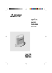
1
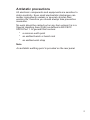
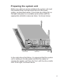
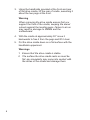
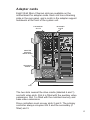
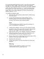
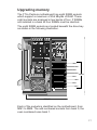
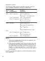
ADD-ON INSTALLATION GUIDE
FT//e Pentium
apricot
MITSUBISHI ELECTRIC
Pentium and OverDrive are trademarks of Intel Corporation.
Micro Channel is a trademark of International Business Machines Corporation.
Information contained in this document is subject to change without notice and
does not represent a commitment on the part of Apricot Computers Limited. The
software described in this manual is furnished under a license agreement. The
software may be used or copied only in accordance with the terms of this
agreement.
It is against the law to copy any disk supplied for any purpose other than the
purchaser’s personal use.
All rights reserved; no use or disclosure without written consent.
Copyright © Apricot Computers Limited 1993
Published by
Apricot Computers Limited
3500 Parkside
Birmingham Business Park
B37 7YS
MITSUBISHI ELECTRIC
Printed in the United Kingdom
Part no. 15225331
Contents
Introduction 2
Antistatic precautions 3
Power down procedure 4
Power up procedure 4
Preparing the system unit 5
Removing the side panel 6
Removing the drive cradle 7
Adapter cards 9
Upgrading memory 11
Processor upgrades 15
Supplier upgrades 21
1
Introduction
This guide contains instructions on installing expansion
cards, extra memory and processor upgrades in your
computer. This document should be your only source of
information when installing any of these.
You should read this document before purchasing extra
memory or a processor upgrade. If, having read the
relevant instructions, you are not confident about installing
the upgrade, you may wish to have your supplier or service
organization install it for you.
Before you start installing an upgrade you should be
thoroughly familiar with all the relevant instructions in this
guide.
Warning
Never carry out any work on the equipment with power
applied. Always switch off at the mains, isolate the
batteries and remove the power lead from the equipment
before starting work.
At the rear of this guide is some information about drive
upgrades. These options are not user installable items,
only competent service personnel may install them.
2
Antistatic precautions
All electronic components and equipments are sensitive to
static electricity. Even small electrostatic discharges can
render components useless or severely shorten their
working life, therefore you should always take preventive
measures.
No work should be carried out on any item unless it is in a
Special Handling Area (SHA) as defined in BS CECC
00015:Part 1. In general this involves:
* a common earth point
* an earthed bench or bench mat
* an earthed wrist strap
Note
An antistatic earthing point is provided on the rear panel.
3
Power down procedure
If LOC Technology is in use, a user of appropriate authority
must be logged on before the system can be powered
down.
1. Push the POWER button and hold it until the system
powers down.
2. Isolate the UPS batteries by setting the Battery
Power switch to the ‘0’ position.
3. Unplug the mains power supply.
Power up procedure
1. Ensure that the Battery Power switch is in the ‘0’
position.
2. Plug in the mains power supply.
4. Set the Battery Power switch to the ‘1’ position.
5. Push the POWER button.
6. Perform any required power-on security procedure.
4
WRIST STRAP
BENCH MAT
KEYBOARD
MOUSE
VIDEO
PARALLEL
SERIAL
ANTI-STATIC
GROUND POINT
AKKUMULATOR TRENNSCHALTER
INTERRUPTEUR
D'ISOLATION
DE LA BATTERIE
I
O
BATTERY ISOLATION
SWITCH
AC INPUT
100V-120V
~
220V-240V
~
50-60Hz
6.0A
3.0A
THIS APPLIANCE
MUST BE EARTHED
:
:
:
A DJNVJCCCKCKCZCKZCOZCZ
FXVGFCV
CKLCKCCKCKCKC OO9D0DQVVVCCCX
HADCUCIHUXCBBBLFR3JAS
DXJDXIOJIDS
IDHCUASDHJCAGBBKLKIOD
JADXASSXQ
PUOASDAICJASIJCASIDAI
CAS
ATTACH SERIAL No
LABEL HERE
8
7
5
4
3
2
1
6
APRICOT COMPUTERS
LIMITED
a divisional company
MITSUBISHI ELETRIC
UK LIMITED
UPS STATUS
REFER TO INSTALLATION
INSTRUCTIONS
BEFORE CONNECTING TO SUPPLY
DISCONNECT FROM SUPPLY
AND ISOLATE
BATTERY BEFORE SERVICING
OR
REMOVING COVERS
VOR ANSCHLIEBEN DES GERATES
DIE
BEDIENUNGS-ANLEITUNG LESEN
VOR WARTUNG DES GERATES
ODER
ENTFERNEN DER GEHAUSEDECKEL
NETZSTECKER ZIEHEN UND
BATTERIE ISOLIEREN
VOIR LA NOTICE D'INSTALLATION
AVANT DE RACCORDER AU
RESEAU
RECONNECTEUR DU SECTEUR
ET /
^
ISOLER LA BATTERIE AVANT
L'OUVERTURE DU PANNEAU
DE COTE
OU TOUTE INTERVENTION
SUR LA MACHINE
Preparing the system unit
Before any add-ons can be installed, the system unit must
be powered down and disconnected from the power
supply, as described earlier. It must also be resting flat on
the right side panel on a suitable work surface with the
appropriate antistatic measures taken. As shown below:
BENCH
In the instructions that follow, it is assumed that the system
unit is resting on its side panel and that the reader is
viewing the system unit from the front, with the drive cradle
door to the right, as shown above.
5
6
5. Lift the panel off.
MOUSE
KEYBOARD
VIDEO
PARALLEL
SERIAL
ANTI-STATIC
GROUND POINT
AKKUMULATOR TRENNSCHALTER
INTERRUPTEUR
D'ISOLATION
DE LA BATTERIE
I
O
BATTERY ISOLATION
SWITCH
AC INPUT
100V-120V
~
220V-240V
~
50-60Hz
6.0A
3.0A
THIS APPLIANCE
MUST BE EARTHED
:
:
:
A DJNVJCCCKCKCZCKZCOZC
ZFXVGFCV
CKLCKCCKCKCKC OO9D0DQVVVCCCX
HADCUCIHUXCBBBLFR3JA
SDXJDXIOJIDS
IDHCUASDHJCAGBBKLKIO
DJADXASSXQ
PUOASDAICJASIJCASIDA
ICAS
ATTACH SERIAL No
LABEL HERE
8
7
5
4
3
2
1
6
APRICOT COMPUTERS
LIMITED
a divisional company
MITSUBISHI ELETRIC
UK LIMITED
UPS STATUS
REFER TO INSTALLATION
INSTRUCTIONS
BEFORE CONNECTING TO SUPPLY
DISCONNECT FROM SUPPLY
AND ISOLATE
BATTERY BEFORE SERVICING
OR
REMOVING COVERS
VOR ANSCHLIEBEN DES GERATES
DIE
BEDIENUNGS-ANLEITUNG LESEN
VOR WARTUNG DES GERATES
ODER
ENTFERNEN DER GEHAUSEDECKEL
NETZSTECKER ZIEHEN UND
BATTERIE ISOLIEREN
VOIR LA NOTICE D'INSTALLATION
AVANT DE RACCORDER AU
RESEAU
RECONNECTEUR DU SECTEUR
ET
^ /
ISOLER LA BATTERIE AVANT
L'OUVERTURE DU PANNEAU
DE COTE
OU TOUTE INTERVENTION
SUR LA MACHINE
Removing the side panel
To install any of the add-ons described here it is necessary
to obtain access to the motherboard. This requires the
removal of the left side panel as described below:
1. Prepare the system unit as described above.
2. Unlock the security lock on the rear panel.
3. Unscrew the two thumbscrews.
CASING THUMBSCREWS
4. Slide the panel back about 15mm to free it from
the lugs.
Removing the drive cradle
In order to install SIMMs it is necessary to remove the drive
cradle. With the side panel removed as described in
Removing the side panel the drive cradle can be removed
as described below:
1. Undo the eight thumbscrews that secure the drive
cradle.
SIGNAL
CABLE
POWER
CABLE
HANDHOLD
DRIVE CRADLE
SECURING
THUMBSCREWS
DRIVE CRADLE
SECURING
THUMBSCREWS
HANDHOLD
PIVOT PINS
2. Disconnect the power cable(s) from the power
supply, and the signal cable(s) from the connectors
on the drive cradle.
7
3. Using the handholds provided at the front and rear
of the drive cradle, lift the rear of cradle, swivelling it
about the two pegs at the front.
Warning
When removing the drive cradle ensure that you
support the front of the cradle, keeping the swivel
cutouts against the locating pegs. Failure to do so
may result in damage to SIMMs and the
motherboard.
4. With the cradle at approximately 30° move it
backwards to free it from the pegs and lift it clear.
5. Put the drive cradle down on a flat surface with the
handholds uppermost.
Warnings
1. Ensure that the drive cradle is stable.
2. The surface the drive cradle rests on must be
flat, any irregularity may come into contact with
the drives in the cradle and damage them.
8
Adapter cards
Eight 32-bit Micro Channel slots are available on the
motherboard for adapter cards. Each slot has a blanking
plate in the rear panel, and a notch in the adapter support
metalwork at the front of the system unit.
EXPANSION
SLOTS
BLANKING
PLATE
ADAPTER
SUPPORT
METALWORK
SECURING
SCREW
FAN
FRONT
The two slots nearest the drive cradle (labelled 6 and 1)
are both video slots. Slot 6 is fitted with the auxiliary video
extensions. Slot 1 is fitted with the matched memory and
base video extensions.
Drive controllers must occupy slots 2 and 3. The primary
controller always occupies slot 2 and the secondary (if
fitted) slot 3.
9
It is recommended that slots 6 and 1 are left unoccupied
(except for video cards), and slot 3 is left unoccupied
(except for a secondary drive controller). Any other adapter
cards should be fitted in slots 4, 5, 7 and 8 working down
the system unit. Only after all these slots are full should
cards other than video adapters or drive controllers be
fitted in slots 6, 1 or 3.
To install an adapter card:
1. Remove the side panel as described in Removing
the side panel.
2. Loosen the thumbscrew at the bottom of the
blanking plate for the slot that the adapter is to
occupy, and remove the blanking plate.
Note
If the thumbscrew is tight it may be necessary to
use a screwdriver to release it.
3. Holding the adapter card only by the plastic fixings,
position it above the required connector. Make sure
that the front edge of the card locates in the
appropriate notch in the adapter support metalwork.
4. Using the plastic fixings, push the card firmly into
the connector. Do not use excessive force.
5. Secure the card by tightening the thumbscrew at the
bottom of the rear panel of the card.
6. Replace the side panel.
7. Power the system up and reconfigure for the new
adapter.
Warning
Always ensure that the system unit is fully
reassembled before powering it up.
10
Upgrading memory
The FT//e Pentium motherboard has eight SIMM sockets
which support a maximum of 256 Mbytes of RAM. These
eight sockets are arranged in two banks of four. If SIMMs
are installed in a bank all four SIMMs must be identical.
The eight SIMM sockets are located beneath the drive bay
as shown in the following illustration.
MM8
MM7
MM6
MM5
SIMMS
MM4
MM3
MM2
MM1
FRONT
Each of the sockets is identified on the motherboard, from
MM1 to MM8. The odd numbered sockets form bank 0, the
even numbered ones bank 1.
11
Apricot supplies and supports upgrades of 16, 32, 64 and
128 Mbyte capacities. The following table lists the possible
capacities:
Bank capacity (Mbytes)
Bank 0
Bank 1
16
16
32
32
32
64
64
64
64
128
128
128
128
128
16
16
32
16
32
64
16
32
64
128
Total capacity
(Mbytes)
16
32
32
48
64
64
80
96
128
128
144
160
192
256
Note
For all cases the SIMMs in bank 0 could be swapped with
those in bank 1 with no adverse affect.
12
Installing SIMMs
Obtaining access
To obtain access to the SIMM sockets you must remove,
the side panel as described in Removing the side panel,
and the drive cradle as described in Removing the drive
cradle.
Removing SIMMs
If you wish to install an upgrade in a bank which is already
occupied you must first remove the existing SIMMs. For
each SIMM in the bank:
1. Lever the metal clips on each side of the socket
gently away from the SIMM using your forefingers.
2. Place your thumbs on the top edge of the SIMM and
move it gently towards the vertical.
3. When the SIMM has rotated through 20°, taking care
to avoid touching any of the components on the
SIMM, grip the top corners of the SIMM between
thumb and first finger and carefully pull the SIMM out
of the socket.
Inserting SIMMs
For each socket in the bank:
1. The SIMM will only install in one orientation. There
is a cutout at one end of the SIMM next to the
connector strip.
Hold the SIMM with the cutout on the left and the
metal connector strip nearest the motherboard.
13
2. Position the SIMM above the socket with the SIMM
tilted slightly towards the rear of the system unit.
3. Lower the SIMM into the socket, and ensure that
the SIMM is properly located in the connector.
4. Pushing gently on the top corners rotate the SIMM
towards the horizontal until it clips into place. Do not
use excessive force.
If the SIMM will not rotate easily remove it and start
again.
5. If the SIMM is properly located the SIMM should
remain in position held by the securing clips, and
with a small plastic lug through the holes on either
side of the SIMM.
Once you have installed all the SIMMs you can reassemble
the system.
Warning
When replacing the drive cradle, make sure that you keep
the cradle locating pins as far as possible into the cutouts
at the front of the drive cradle, while you swivel the cradle
back into place.
14
Processor upgrades
The FT//e Pentium motherboard is fitted with a Zero
Insertion Force (ZIF) processor socket, ready for higher
performance Pentium variants as they become available.
The FT//e Pentium motherboard is ready to accept any
processor with a Pentium compatible pinout, and a
maximum external clock speed of 60MHz.
15
Removing the processor
Before installing the upgrade processor you must first
remove the existing processor. The processor is at the
front left of the motherboard beneath the fan assembly.
Instructions on locating the socket and removing a
processor are given below.
1. Remove the side panel as described in Removing
the side panel.
2. Note the position of all adapter cards and adapter
cabling.
3. Disconnect all adapter cables and remove the
adapters.
4. Disconnect the fan power cable, and remove the
two screws that secure the fan assembly.
SECURING
SCREWS
FAN
16
FRONT
5. Lift the fan assembly out of the system.
6. Identify the processor.
PROCESSOR
FRONT
The processor is installed in a ZIF socket. A lever
attached to the socket clamps the processor
securely in the socket when it is parallel to the
motherboard.
17
7. Carefully rotate the lever from the secure position
until it is perpendicular to the motherboard
FREE
LOCKED
The first and last 15° of movement may require
considerable effort. Apply just enough pressure to
overcome the resistance offered by the lever.
8. Once the processor is free of its socket lift it out of
the system unit and place it on the anti-static foam
provided with the upgrade processor.
18
Installation
You are ready to install your new upgrade processor.
1. The upgrade processor and socket are keyed to
ensure that the processor can only be installed in
one orientation.
One corner of the socket has an extra hole inside
the others, the processor has a corresponding extra
pin. The processor has a small dot of paint on its
top surface to indicate the corner with the extra pin.
If the processor has a heatsink fitted the paint dot
may not be visible. Use the illustration below to help
you identify the keyed corner.
POSITIONING
GUIDE
KEYED
CORNER
FRONT
19
2. Carefully position the upgrade processor above the
socket with the positioning guide on the processor
over the keyed corner of the socket and the
securing lever in the perpendicular position.
PROCESSOR
IN CENTRE
Warning
If the processor is misaligned it will not go into the
socket, and any attempt to force it will damage the
processor, or the socket, or both.
3. Gently insert the upgrade processor making sure
that it is correctly aligned with the socket and that
you do not bend or otherwise damage the pins.
4. Once you are certain that all the pins on the
processor are in the holes in the socket carefully
move the securing lever to the locked position.
The lever may require a considerable amount of
force in order to lock the processor in place. Take
care to exert no more force than is necessary.
5. You may now reassemble the system unit.
20
Supplier upgrades
The add-ons described earlier may be installed by a
confident and competent user. The installation of additional
(or replacement) drives is more complex, and should only
be carried out by competent service personnel.
Installing additional drives
The Apricot FT//e provides a drive cradle that contains two
bays with space for a maximum of five drives. These are:
* Two 1/2 height drives at the front of the system unit.
* Up to three SCSI hard disk drives at the rear of the
system unit.
Notes
1. The first 3.5" floppy drive is not installed in the drive
cradle. It is attached, via a mounting plate, to the
power supply.
2. Drives available for the front bay include: 3.5" SCSI
hard disk drives, 5.25" floppy drive, 5.25" SCSI tape
drives and a 5.25" CD-ROM drive. Any two of these
may be fitted.
21
Expansion options
The following table lists the possible upgrade routes for
each possible combination of drives in each bay:
Drive Current
bay
configuration
Possible
expansion
Rear
One 1" high drive
One 1/2 height drive
or
One or two 1" inch high drives
Two 1" high drives
One 1" inch high drive
One 1/2 height drive One 1/2 height drive
or
One 1" inch high drive
Front
No drive
One full height drive
or
One or two 1/2 height drives
or
One 1" high drive
or
One 1/2 height and one 1" high
drive
One 1/2 height drive One 1/2 height drive
or
One 1" inch high drive
One 1" high drive
One 1/2 height drive
Notes
1. The only full height drive that Apricot supplies is an
autoloading DDS-DC drive.
2. If two drives are fitted in the front drive bay, they can
be either two half height removable media drives, or
one half height removable media drive and one half
height or 1" high hard disk drive. If a hard disk drive
is fitted in the front drive bay it must be in the right of
the two slots.
Contact your Apricot supplier for further information about
drive upgrades.
22
apricot
APRICOT COMPUTERS LIMITED
3500 PARKSIDE
BIRMINGHAM BUSINESS PARK
BIRMINGHAM B37 7YS.
MITSUBISHI ELECTRIC
Part No 15225331
Revision No 01