1
SERVICE MANUAL
CODE: 00ZMXFNX1/S1E
DIGITAL FULL COLOR
MULTIFUNCTIONAL SYSTEM OPTION
FINISHER / PUNCH MODULE
MODEL
MX-FNX1
MX-PNX1A/B/C/D
CONTENTS
[1] PRODUCT OUTLINE . . . . . . . . . . . . . . . . . . . . . . . . . . . . . . . . . . . 1-1
[2] SPECIFICTIONS . . . . . . . . . . . . . . . . . . . . . . . . . . . . . . . . . . . . . . . 2-1
[3] UNPACKING AND INSTALLATION
* For how to unpacking and installation, refer to the installation manual (00ZMX2700/I1E).
[4] EXTERNAL VIEW AND INTERNAL STRUCTURE . . . . . . . . . . . . . 4-1
[5] OPERATIONAL DESCRIPTIONS . . . . . . . . . . . . . . . . . . . . . . . . . . 5-1
[6] DISASSEMBLY AND ASSEMBLY . . . . . . . . . . . . . . . . . . . . . . . . . . 6-1
[7] MAINTENANCE. . . . . . . . . . . . . . . . . . . . . . . . . . . . . . . . . . . . . . . . 7-1
[8] ADJUSTMENTS . . . . . . . . . . . . . . . . . . . . . . . . . . . . . . . . . . . . . . . 8-1
[9] SELF DIAGNOSTICS AND TROUBLE CODES . . . . . . . . . . . . . . . 9-1
[10] ELECTRICAL SECTION . . . . . . . . . . . . . . . . . . . . . . . . . . . . . . . . 10-1
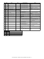
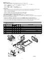
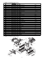
PARTS GUIDE
Parts marked with " " are important for maintaining the safety of the set. Be sure to replace these parts with
specified ones for maintaining the safety and performance of the set.
SHARP CORPORATION
This document has been published to be used
for after sales service only.
The contents are subject to change without notice.
CONTENTS
[1] PRODUCT OUTLINE. . . . . . . . . . . . . . . . . . .1-1
[6] DISASSEMBLY AND ASSEMBLY
1. MX-FNX1 . . . . . . . . . . . . . . . . . . . . . . . . 6-1
[2] SPECIFICTIONS
2. MX-PNX1A/B/C/D . . . . . . . . . . . . . . . . . 6-11
1. MX-FNX1 . . . . . . . . . . . . . . . . . . . . . . . . .2-1
2. MX-PNX1A/B/C/D . . . . . . . . . . . . . . . . . .2-1
[7] MAINTENANCE
1. Maintenance system table . . . . . . . . . . . 7-1
[3] UNPACKING AND INSTALLATION
* For how to unpacking and installation, refer to the
installation manual (00ZMX2700/I1E).
[8] ADJUSTMENTS
1. Setting item list . . . . . . . . . . . . . . . . . . . . 8-1
2. Details . . . . . . . . . . . . . . . . . . . . . . . . . . . 8-1
[4] EXTERNAL VIEW AND INTERNAL
STRUCTURE
1. Identification of each section and
functions . . . . . . . . . . . . . . . . . . . . . . . . . .4-1
[5] OPERATIONAL DESCRIPTIONS
[9] SELF DIAGNOSTICS AND TROUBLE CODES
1. Trouble code and troubleshooting. . . . . . 9-1
[10] ELECTRICAL SECTION
1. Electrical mechanism diagram . . . . . . . . .5-1
1. Circuit descriptions . . . . . . . . . . . . . . . . 10-1
2. General. . . . . . . . . . . . . . . . . . . . . . . . . . .5-5
2. Block diagram . . . . . . . . . . . . . . . . . . . 10-12
3. Outline of the transport path . . . . . . . . . . .5-5
3. Actual wiring diagram . . . . . . . . . . . . . 10-14
4. Non-sort mode . . . . . . . . . . . . . . . . . . . . .5-6
5. Offset mode . . . . . . . . . . . . . . . . . . . . . . .5-6
6. Staple mode . . . . . . . . . . . . . . . . . . . . . . .5-7
7. Punching process. . . . . . . . . . . . . . . . . . .5-9
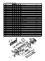
PARTS GUIDE
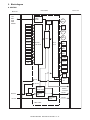
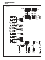
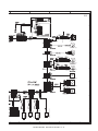
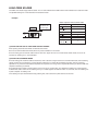
[1] PRODUCT OUTLINE
âºíuÇ´
Service Manual
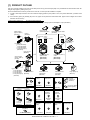
This unit is used by installing to the main unit for after-process of copy and FAX output paper. It is provided with the offset function which discharges output paper by shifting one by one.
Since it is installed to the center tray section of the main unit, no extra space for installation is required.
1)
3 kinds of auto staple functions: There are 3 kinds of stapling positions. (One position in front, one position backward, 2 positions at the
center).
2)
Punch function (option): By installing the punch unit, paper can be punched to make binder holes. (Paper of 64 to 128g/m2 can be used.
OHP film cannot be used.)
Models enable to install the unit
MX-2300G/2700G/2300N/2700N
The finisher requires a staple cartridge as a consumable part. (Staple cartridge (about 5,000 staples x 3 pcs.) MX-SCX1)
Staple cartridge
(Approx. 5000 x 3)
(MX-SCX1)
Device Tray with
USB Hub (MX-RKX1)
Finisher
(MX-FNX1)
Reversing single pass feeder
(MX-RPX1)
SPLC-c
driver
PCL5c/PCL6 Network
scanner
driver
(Sharpdesk 1 license)
Punch module
● 2-hole (MX-PNX1A)
● 3-hole (MX-PNX1B)
● 4-hole (MX-PNX1C)
● 4-hole (broad space)
(MX-PNX1D)
Paper pass unit
(MX-RBX1)
Saddle stitch finisher
(MX-FNX2)
Barcode font kit
CD
HDD
HDD
Staple cartridge
(Approx. 5000 x 3)
(AR-SC2)
Punch module
● 2-hole (AR-PN1A)
● 3-hole (AR-PN1B)
● 4-hole (AR-PN1C)
● 4-hole (broad space)
(AR-PN1D)
Document cover
(MX-VRX1)
RSPF
Exit tray unit
(MX-TRX1)
Copier/Printer (PCL)
/Scanner model
Copier/Printer (SPLC-c)
model
(MX-2300N)
(MX-2700N)
(MX-2300G)
(MX-2700G)
Stand/1x500 sheet
paper drawer
(MX-DEX1)
Printer expansion
kit (PCL)
Stand/2x500 sheet
paper drawer
(MX-DEX2)
Network scanner
expansion kit
Large capacity tray
(MX-LCX1)
PS3 expansion
kit
Facsimile
expansion kit
(MX-FXX1)
ROM
CD
(AR-PF1)
(MX-PBX1)
Data security kit
CD
CD
ROM
(MX-NSX1)
(MX-PKX1)
(For MX-2300G/2700G)
FAX memory (8MB)
(packed together)
(Including document control)
CC authentication
version
Security
ROM
Internet Fax
expansion kit
Commercial
version
Sharpdesk
1 license kit
Sharpdesk
5 license kit
Sharpdesk
10 license kit
Sharpdesk
50 license kit
Security
ROM
CD
(MX-FWX1)
For document
control PWB
For document
control PWB
(MX-FRX1)
(MX-FRX1U)
Application
integration
module
CD
CD
(MX-USX1/
USX5)
(MX-US10/
US50)
Sharpdesk
100 license kit
Application
communication
module
External
account module
256MB expansion memory board
(MX-SMX1)
CD
(For MX-2300G/2700G)
(MX-AMX1)
CD
(MX-USA0)
CD
(MX-AMX2)
MX-FNX1/MX-PNX1 PRODUCT OUTLINE 1 – 1
CD
(MX-AMX3)
[2] SPECIFICTIONS
âºíuÇ´
Service Manual
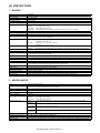
1. MX-FNX1
Type
Loading method
Transport speed
Tray type
Transport reference
Paper exit direction
Paper weight
Mode type
Paper sizes allowed for offset
Offset quantity
Discharged paper size
Sortable size
Stack tray max. load capacity
Staplable paper weight
Staplable paper size
Staplable paper quantity (Max.)
Stapling
Staple supply system
Staple detection
Manual stapling
External dimensions (W x D x H)
Weight
Power source
Power consumption
Installation/maintenance
Optional detection
Packaged items
Inner finisher
Offset tray
23, 27, 35, 45 PPM
Offset tray
Center reference
Face down
Plain paper:
60 to 105g/m2 (16 to 28 lbs)
Thin paper:
55 to 59g/m2 (15 to 16 lbs)
Heavy paper:
106 to 209g/m2 (28 to 56 lbs)
Special paper: OHP sheet, label sheet, envelopes, tab paper: Limited to non-sort (up to 10 sheets).
Non-stapled, stapled
A3, B4, A4, A4R, B5, 8K, 16K, 11" x 17", 8.5" x 14", 8.5" x 13", 8.5" x 11", 8.5" x 11"R
30mm, 1.2 inch
A3, B4, A4, A4R, A5R, B5, B5R, 8K, 16K, 16KR, 12" x 18", 11" x 17", 8.5" x 14", 8.5" x 13", 8.5" x 11", 8.5" x 11"R,
5.5" x 8.5"R, 7.25" x 10.5"R, A3 wide, special paper
Metric series
Large size: A3, B4, 8K
Small size: A4, A4R, B5, 16K
Inch series
Large size: 11" x 17", 8.5" x 14", 8.5" x 13"
Small size: 8.5" x 11", 8.5" x 11"R
Large size:
Max. 250 sheets or max. 30 sets or 35.5mm
Small size:
Max. 500 sheets (For special paper, max. 10 sheets can be loaded on the tray.) or max. 30 sets or 71mm
60 to 128g/m2 (16 to 34 lbs) * However, "106 to 128g/m2 (28 to 34 lbs)" is enable only for two sheets.
A3, B4, A4, A4R, B5, 8K, 16K, 16KR, 11" x 17", 8.5" x 14", 8.5" x 13", 8.5" x 11", 8.5" x 11"R
Max. 50 sheets (for small size, 90g/m2 (24 lbs))
Max. 30 sheets (for large size, 90g/m2 (24 lbs))
3 kinds (One position in front, one position backward, 2 positions).
Staple sheet cartridge replacement system (Staple cartridge (Approx. 5,000 x 3 pcs.) MX-SCX1)
Staple empty detection (Near empty detection: 20 staples remained)
No
440 x 595 x 205 (mm), 17 21/64 x 23 27/64 x 8 5/64 (inch)
(with tray extended: 640 x 595 x 205 (mm), 25 12/64 x 23 27/64 x 8 5/64 (inch))
Approx. 13kg (28.7 lbs)
Supplied from the main unit power source. (DC24V, DC5V)
55.2W
Installed by service personnel
Auto detection supported
Parts for mounting, operational sheet, staple directional instruction label, installation cautionary note
2. MX-PNX1A/B/C/D
Type
Punch type
Transport speed
Transport reference
Punch dust full detection
Paper exit direction
Paper weight
Punchable paper size
Power source
External dimensions (W x D x H)
Weight
Packaged items
Punch unit for the inner finisher
2 holes / 3 holes / 4 holes / 4 holes (wide)
A punch unit that provides all of these 4 types can be installed.
23, 27, 35, 45 PPM
Center reference
YES (Lever system)
Face down
Plain paper:
60 to 105g/m2 (16 to 28 lbs)
Thin paper:
55 to 59g/m2 (15 to 16 lbs)
Heavy paper:
106 to 209g/m2 (28 to 56 lbs)
2 holes
A3, B4, A4, A4R, B5, B5R, 11" x 17", 8.5" x 14", 8.5" x 13", 8.5" x 11", 8.5" x 11"R, 8K, 16K, 16KR
(MX-PNX1A)
3 holes *1
3 holes: A3, A4, 11" x 17", 8.5" x 11"
(MX-PNX1B)
2 holes: 8.5" x 14", 8.5" x 13", 8.5" x 11"R
4 holes
A3, A4
(MX-PNX1C)
4 holes (wide) A3, B4, A4, A4R, B5, B5R, 11" x 17", 8.5" x 14", 8.5" x 13", 8.5" x 11", 8.5" x 11"R
(MX-PNX1D)
Supplied from the inner finisher. (DC24V, DC5V)
105 x 518 x 170 (mm), 4 9/64 x 20 25/64 x 6 45/64 (inch)
Approx. 3.5kg (7.7 lbs)
Parts for mounting, instructional label for punch direction, instructional label for garbage pickup, installation cautionary note
*1: Auto switching: 2 holes/3 holes
MX-FNX1/MX-PNX1 SPECIFICTIONS 2 – 1
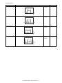
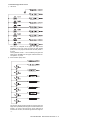
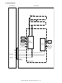
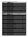
Kind of hole punch
Kind
2 holes (MX-PNX1A)
Hole position
A: 80±1mm
B: 12±3mm
Hole size
φ6.5mm
A
B
3 holes (MX-PNX1B)
A
A: 108±1mm
B: 12±3mm
φ8.0mm
A: 80±1mm
B: 12±3mm
φ6.5mm
A: 70±1mm
B: 12±3mm
C: 21±1mm
φ6.5mm
A
B
4 holes (MX-PNX1C)
A A A
B
4 holes (wide) (MX-PNX1D)
A
C
B
MX-FNX1/MX-PNX1 SPECIFICTIONS 2 – 2
âºíuÇ´
Service Manual
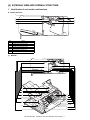
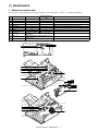
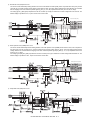
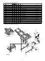
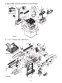
[4]
EXTERNAL VIEW AND INTERNAL STRUCTURE
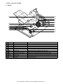
1. Identification of each section and functions
A. Internal structure
1
5
2
3
4
No.
1
2
3
4
5
6
7
6
7
Name
Paper exit roller
Bundle exit paper transport roller
Paper exit roller
Bundle exit paper transport roller
Inlet port paper transport roller
Inlet port paper transport roller
Take-up belt
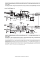
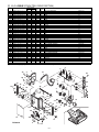
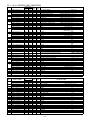
B. Sensors and switches
(1)
MX-FNX1
1
2
3
4
11
10
12
5
6
15
13
16,17,18
14
8
9
7
MX-FNX1/MX-PNX1 EXTERNAL VIEW AND INTERNAL STRUCTURE 4 – 1
No.
1
Signal
FULD
Name
Tray upper limit sensor
Type
Photo interrupter
2
FMLLD
Photo interrupter
3
FLLD
Tray intermediate lower limit
sensor
Tray lower limit sensor
Photo interrupter
4
FBED
Tray paper empty sensor
Photo interrupter
5
6
FSLD1
FSLD2
Paper surface sensor 1
Paper surface sensor 2
Photo interrupter
Photo interrupter
7
FSTHPD
Stapler HP sensor
Photo interrupter
8
FSTPD
Empty sensor
Photo interrupter
9
FFJHPD
Alignment plate HP sensor F
Photo interrupter
10
FRJHPD
Alignment plate HP sensor R
Photo interrupter
11
FED
Inlet port sensor
Photo interrupter
12
FRLD
Roller up/down sensor
Photo interrupter
13
FBRD
Take-up belt sensor
Photo interrupter
14
FDSW
Front cover switch
Photo interrupter
15
FJPD
Alignment plate position sensor
Photo interrupter
16
FSHPD
Stapler home sensor
17
FSD
Staple empty sensor
18
FSTD
Self priming sensor
FSLD1
TP5
“L”
“H”
“H”
“L”
FSLD2
TP6
“H”
“H”
“L”
“L”
Function/Operation
Detects the upper limit position of the
paper load tray up/down shift area.
Detects the intermediate position of the
paper load tray up/down shift area.
Detects the lower limit position of the
paper load tray up/down shift area.
Detects paper empty in the paper load
tray.
Detects the surface position of paper on
the tray in combination of the both sensors
outputs.
Detects the home position of the stapler
unit in F/R direction shift.
Detects paper empty on the process tray.
Detects the home position of the alignment
guide on F side.
Detects the home position of the alignment
guide on R side.
Detects paper in the inlet port of the
finisher.
Detects the upper standby position of up/
down movement of the bundle exit roller.
Detects up/down positions of the take-up
belt.
Detects open/close of the jam release
cover in the front section.
Detects entry of the process section rear
edge stopper into the opening of the
stapler and inhibits stapling.
Detects the home position of the stapling
mechanism. (Sensor built in the stapler
unit)
Detects staple empty. (Sensor built in the
stapler unit)
Detects the staple feed is completed and it
is ready for stapling. (Sensor built in the
stapler unit)
Output
TP1 is driven to “L” at the upper limit
position.
TP2 is driven to “L” at the intermediate
position.
TP3 is driven to “L” at the lower limit
position.
TP4 is driven to “L” when paper is
provided.
*Refer to the separate table outside the
column.
TP7 is driven to “H” at the home position.
TP8 is driven to “H” when paper is
provided.
TP9 is driven to “L” at the home position.
TP10 is driven to “L” at the home position.
TP11 is driven to “H” when paper is
provided.
TP12 is driven to “L” when the roller
reaches the upper standby position.
TP13 is driven to “L” when the take-up belt
is on the upper side.
TP15 is driven to “L” when the cover is
closed.
TP50 is driven to “L” when the stopper
enters the opening of the stapler.
TP51 is driven to “H” at the home
(standby) position.
TP53 is driven to “L” when staple empty.
TP52 is driven to “H” when in the ready
state.
State
The paper detection lever is in the save position.
The paper surface is upper than the reference level.
The paper surface is at the reference level.
The paper surface is lower than the reference level.
MX-FNX1/MX-PNX1 EXTERNAL VIEW AND INTERNAL STRUCTURE 4 – 2
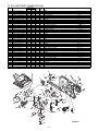
(2)
MX-PNX1A/B/C/D
3
11
10
9
8
7
6
4
2
1
5
No.
1
Signal
FPDD
Name
Full sensor
Type
Photo interrupter
Function/Operation
Detects full of the punch dust container.
2
FPHPD
Photo interrupter
3
FPRPD
4
FPSHPD
5
FPPEND
6
FPPD1
7
FPPD2
8
FPPD3
Punch position
sensor
Rear position
sensor
Horizontal shift
HP sensor
Paper rear edge
sensor
Paper horizontal
resist sensor 1
Paper horizontal
resist sensor 2
Paper horizontal
resist sensor 3
9
FPPD4
10
FPPD5
Paper horizontal
resist sensor 4
Paper horizontal
resist sensor 5
Transmission type
sensor
Transmission type
sensor
11
FPPD6
Paper horizontal
resist sensor 6
Transmission type
sensor
Detects the home position of the punch up/down
shift.
Detects the lower limit position of 3-hole side up/
down shift in 2/3-hole punching.
Detects the home position in the punch position
horizontal resist correction mechanism.
Detects the lead edge and the rear edge of paper
to be punched.
Detects the paper edge in the rear side of B5R or
7.25" x 10" R size width direction of the machine.
Detects the paper edge in the rear side of 16K-R
size width direction of the machine.
Detects the paper edge in the rear side of 8.5"
x14", 8.5" x 11"R, 8.5" x 13", or A4R size width
direction of the machine.
Detects the paper edge in the rear side of B4 or
B5 size width direction of the machine.
Detects the paper edge in the rear side of 11" x
17", 8.5" x 11", 8K, or 16K size width direction of
the machine.
Detects the paper edge in the rear side of A3 or
A4 size width direction of the machine.
Photo interrupter
Photo interrupter
Transmission type
sensor
Transmission type
sensor
Transmission type
sensor
Transmission type
sensor
Output
When full, TP2 on the punch PWB remains
“H” level.
TP47 on the control PWB of the inner finisher
is driven to “H” at the home position.
TP48 on the control PWB of the inner finisher
is driven to “H” at the lower limit position.
TP49 on the control PWB of the inner finisher
is driven to “H” at the home position.
TP54 on the control PWB of the inner finisher
is driven to “L” when paper is provided.
TP55 on the control PWB of the inner finisher
is driven to “L” when paper is provided.
TP55 on the control PWB of the inner finisher
is driven to “L” when paper is provided.
TP55 on the control PWB of the inner finisher
is driven to “L” when paper is provided.
TP55 on the control PWB of the inner finisher
is driven to “L” when paper is provided.
TP55 on the control PWB of the inner finisher
is driven to “L” when paper is provided.
TP55 on the control PWB of the inner finisher
is driven to “L” when paper is provided.
MX-FNX1/MX-PNX1 EXTERNAL VIEW AND INTERNAL STRUCTURE 4 – 3
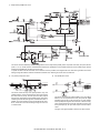
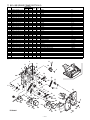
C. Motors, solenoids, and PWB
(1)
MX-FNX1
3
14
12
9
8
5
7
1
4
6
11
2
10
13
No.
1
2
3
4
5
6
7
8
9
10
11
12
13
14
Signal
FFSM
FSM
FTLM
FFJM
FRJM
FSWM
FAM
FRM
FPDS
FSLS
FBRS
FINRPS
FFAN
–
Name
Staple motor
Staple shift motor
Tray motor
Alignment motor F
Alignment motor R
Roller upper/lower roller
Bundle exit motor
Transport motor
Paddle one-rotation solenoid
Paper surface detection solenoid
Belt separation solenoid
Flapper solenoid
Fan
Control PWB
Function
Drives the stapling mechanism. (Stapler unit built-in motor)
Shifts the stapler unit in the F/R direction.
Drives the paper load tray up/down.
Drive the alignment guide on the F side.
Drive the alignment guide on the R side.
Drives the bundle exit roller up/down.
Drives the bundle exit roller and the paddle.
Drives the inlet port roller, the feed roller, and the take-up belt.
Trigger solenoid for paddle one-rotation.
Drives the lever for paper holding and detection of the tray paper surface.
Trigger solenoid for up/down shift of the take-up belt.
Drives the flapper to select the entry path between the finisher inside and the reverse path.
Cools the inlet port of the finisher.
Controls the inner finisher.
MX-FNX1/MX-PNX1 EXTERNAL VIEW AND INTERNAL STRUCTURE 4 – 4
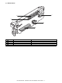
(2)
MX-PNX1A/B/C/D
1
5
4
2
3
No.
1
2
3
4
5
Signal
FPNM
FPSM
–
–
–
Name
Punch motor
Punch horizontal resist motor
Punch PWB
LED light emitting PWB
LED light receiving PWB
Function
Drives the punch unit up/down.
Shifts the punch unit to the center of paper.
Controls the punch unit.
Detects the paper rear edge and the punch horizontal resist.
Detects the paper rear edge and the punch horizontal resist.
MX-FNX1/MX-PNX1 EXTERNAL VIEW AND INTERNAL STRUCTURE 4 – 5
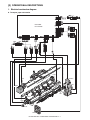
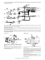
âºíuÇ´
[5]
OPERATIONAL DESCRIPTIONS
Service Manual
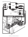
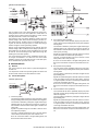
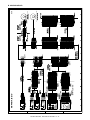
1. Electrical mechanism diagram
A. Transport, paper exit section
PCB-CONT
PF4141K200
FPDS
FRLD
FINRPS
FRM
FSWM
FED
FBRD
FBRS
FDSW
FFAN
MX-FNX1/MX-PNX1 OPERATIONAL DESCRIPTIONS 5 – 1
FAM
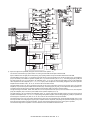
B. Staple section and aligment section
PCB-CONT
PF4141K200
FRJHPD
FRJM
FSTPD
FJPD
FFJM
FFSM
FSHPD(*HP)
FSD(LS)
FSTD(*READY)
FSM
FFJHPD
FSTHPD
MX-FNX1/MX-PNX1 OPERATIONAL DESCRIPTIONS 5 – 2
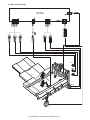
C. Paper exit tray section
PCB-CONT
PF4141K200
FULD
FMLLD
FLLD
FTLM
FSLD1
FBED
FSLD2
FSLS
MX-FNX1/MX-PNX1 OPERATIONAL DESCRIPTIONS 5 – 3
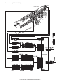
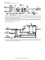
D. Punch unit (MX-PNX1A/B/C/D)
FPRPD
FPPD1~FPPD6
FPHPD
FPPEND
FPNM
FPSHPD
FPDD
FPSM
PCB-PUNCH
YA1035K200
MX-FNX1/MX-PNX1 OPERATIONAL DESCRIPTIONS 5 – 4
2. General
This chapter describes operations of the inner finisher. The major operation modes are as follows:
• Non-sort mode
• Offset mode
• Staple mode
• Non-sort mode + punch
• Offset mode + punch
• Staple mode + punch
In this chapter, the basic operations of the non-sort mode, the offset mode, and the staple mode are described.
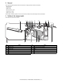
3. Outline of the transport path
The outline of the path is shown below.
1
2 3
15
No.
1
2
3
4
5
6
7
8
Name
Tray
Bundle exit roller
Paddle
Alignment plate
Paper exit roller
Take-up belt
Inlet port sensor (FED)
Inlet port roller
4
5
14
No.
9
10
11
12
13
14
15
6
7 8
13
9
12
Name
Punch pin
Paper rear edge sensor (FPPEND)
Main unit paper exit roller
Stapler
Paper stopper
Empty sensor (FSTPD)
Paper holding lever
MX-FNX1/MX-PNX1 OPERATIONAL DESCRIPTIONS 5 – 5
10
11
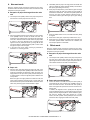
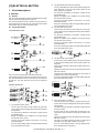
4. Non-sort mode
When the operation mode command is received from the copier,
the finisher makes the finisher operation status command the JOB
and starts the transport operation.
2)
Immediately after the paper rear edge passes the bundle exit
roller, the paddle one-rotation solenoid (FPDS) is turned ON to
take-up the paper falling onto the tray.
3)
When paper is transported by 10mm after the paper rear edge
passes the bundle exit roller, the bundle exit motor (FAM) is
accelerated to 200mm/sec. Just before the paddle passes the
load tray, the paper surface detection solenoid (FSLS) is
turned ON to hold the paper discharged by the paper holding
lever.
4)
When the paddle rotates one turn, the bundle exit motor (FAM)
is stopped.
5)
When there is next paper, repeat the procedures from "A-1)."
6)
When there is no next paper, the actuators are turned OFF and
the finisher operation status command is set to READY, and
the transport operation is terminated.
A. Reception of paper discharged from the main
unit
1)
The transport motor (FRM) is driven at the paper exit speed of
the main unit to receive paper from the main unit.
2)
After turning ON the inlet port sensor (FED), the roller up/down
motor (FSWM) is driven to lower the bundle exit roller. The
bundle exit motor (FAM) is driven at the paper exit speed of the
main unit to drive the bundle exit roller. When the paper width
is 210mm or more, the alignment motor F (FFJM) and the
alignment motor R (FRJM) are driven by turning ON the inlet
port sensor (FED) to shift the alignment plate to 15mm inside
the paper and put it under the paper.
3)
In the case of the punch mode, punching is performed as
described in "7. Punching process."
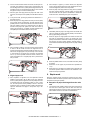
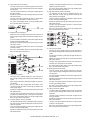
5. Offset mode
When the operation mode command is received from the copier,
the finisher makes the finisher operation status command the JOB
and starts the transport operation.
A. Reception of paper discharged from the main
unit
1)
The transport motor (FRM) is driven at the paper exit speed of
the main unit to receive paper from the main unit. When the
paper length is 216mm or less, the paper exit speed of the second and later sheets from the main unit is 280mm/sec.
B. Paper exit
1)
After the paper rear edge passes the paper exit roller of the
main unit, the transport motor (FRM) and the bundle exit motor
(FAM) are accelerated to 300mm/sec. When the paper rear
edge passes the inlet port sensor (FED) and then transport of
a certain amount is made, the alignment plate is shifted to the
home position.
Before the paper rear edge passes the bundle exit roller, the
paper surface detection solenoid (FSLS) is turned OFF and
the bundle exit roller speed is decelerated to 100mm/sec at the
same time, performing paper exit deceleration of paper.
B. Paper take-up and alignment
1)
For the first sheet of a bundle, the inlet port sensor (FED) is
turned ON and the roller up/down motor (FSWM) is driven to
lower the bundle exit roller. The bundle exit motor (FAM) is
driven at the paper exit speed of the main unit to drive the bundle exit roller.
In addition, the alignment motor F (FFJM) and the alignment
motor R (FRJM) are driven by turning ON the inlet port sensor
(FED) to shift the alignment plate to 15mm outside the paper,
and enter the standby state. After transport of a certain
amount, the roller up/down motor (FSWM) is driven to lift the
bundle exit roller, stopping the bundle exit motor (FAM).
MX-FNX1/MX-PNX1 OPERATIONAL DESCRIPTIONS 5 – 6
2)
For the second and later sheets of a bundle, the inlet port sensor (FED) turns ON and a certain amount is transported, and
then the alignment motor F (FFJM) and the alignment motor R
(FRJM) are driven to shift the alignment plate to 15mm outside
the paper and to put it under the standby state.
3)
After the paper rear edge passes the paper exit roller of the
main unit, the transport motor (FRM) is accelerated to 480mm/
sec.
4)
In the punch mode, punching is performed as described in "7.
Punching process."
5)
When the paper rear edge passes the inlet port sensor (FED)
and a certain amount is transported, the roller up/down motor
(FSWM) is driven to lower the bundle exit roller and the bundle
exit motor (FAM) is driven for a certain amount in the take-up
direction at the paper exit speed of the main unit to take up
paper to the process tray. In addition, the belt separation solenoid (FBRS) is turned ON to lower the take-up belt.
6)
After transport of paper by a certain amount, the alignment
motor F (FFJM) and the alignment motor R (FRJM) are driven
to shift the alignment plate to the home position.
3)
When the paper rear edge passes the empty sensor (FSTPD),
the paper surface detection solenoid (FSLS) is turned OFF
and the bundle exit roller speed is decelerated to 100mm/sec
at the same time, decelerating the paper exit operation.
4)
Immediately after the paper rear edge passes the bundle exit
roller, the paddle one-rotation solenoid (FPDS) is turned ON to
take up paper falling onto the tray.
5)
When the paper rear edge passes the bundle exit roller and
the paper is transported for 10mm, the bundle exit motor
(FAM) is accelerated to 200mm/sec. Before the paddle passes
the load tray, the paper surface detection solenoid (FSLS) is
turned ON to hold the discharged paper with the paper holding
lever.
6)
When the paddle rotates one turn, the bundle exit motor (FAM)
is stopped.
7)
When there is next paper, the procedures are repeated from
"A-1)."
8)
When there is no next paper, the actuators are turned OFF and
the finisher operation status command is set to READY to terminate the transport operation.
After completion of take-up, the roller up/down motor (FSWM)
is driven to lift the bundle exit roller. The alignment motor F
(FFJM) and the alignment motor R (FRJM) are driven for a certain amount to align paper in the process tray. If there are two
or more sheets to be aligned, the procedures are repeated
from "A-1)" for the specified number of sheets. However, the
paper exit operation of "C. Aligned paper exit" is performed for
every 3 sheets.
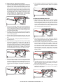
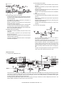
6. Staple mode
C. Aligned paper exit
1)
2)
After completion of alignment, the belt separation solenoid
(FBRS) is turned ON to lift the take-up belt. The alignment
motor F (FFJM) and the alignment motor R (FRJM) are driven
to separate paper from the alignment plate by 1mm. In addition, the roller up/down motor (FSWM) is driven to lower the
bundle exit roller. The bundle exit motor (FAM) is started at the
speed of 450mm/sec and paper in the process tray is discharged.
When the operation mode command is received from the copier,
the finisher makes the finisher operation status command the JOB
and starts the transport operation.
A. Reception of paper discharged from the main
unit
1)
The transport motor (FRM) is driven at the paper exit speed of
the main unit to receive paper from the main unit. When the
paper length is 216mm or less, the paper exit speed of the second and later sheets from the main unit is 280mm/sec.
MX-FNX1/MX-PNX1 OPERATIONAL DESCRIPTIONS 5 – 7
B. Paper take-up, alignment and staple
1)
8)
For the first sheet of a bundle, after turning on the inlet sensor
(FED), the roller up/down motor (FSWM) is driven to lower the
bundle exit roller. The bundle exit motor (FAM) is driven at the
paper exit speed of the main unit to drive the bundle exit roller.
By turning on the inlet port sensor (FED), the alignment motor
F (FFJM) and the alignment motor R (FRJM) are driven to shift
the alignment plate to 15mm outside the paper and to put it
under the standby state. After transport of a certain amount,
the roller up/down motor (FSWM) is driven to lift the bundle
exit roller to terminate the bundle exit motor (FAM).
After completion of alignment of a specified number of sheets,
the staple motor (FFSM) is started to staple at the specified
position.
C. Aligned and stapled paper exit
2)
For the second and later sheets, after transporting paper from
the inlet port sensor (FED) by a certain amount, the alignment
motor F (FFJM) and the alignment motor R (FRJM) are driven
to shift the alignment plate to 15mm outside the paper and to
put it under the standby state.
3)
For the last sheet of a bundle, the inlet port sensor (FED) is
turned ON to drive the staple shift motor (FSM) to shift the stapler to the binding position.
4)
After the paper rear edge passed the paper exit roller of the
main unit, the transport motor (FRM) is accelerated to 480mm/
sec.
5)
In the punch mode, punching is performed as described in "7.
Punching process."
6)
When the paper rear edge passes the inlet port sensor (FED)
and paper is transported by a certain amount, the roller up/
down motor (FSWM) is driven to lower the bundle roller and
the bundle exit motor (FAM) is driven in the take-up direction at
the paper exit speed of the main unit by a certain amount to
take up paper to the process tray. In addition, the belt separation solenoid (FBRS) is turned ON to lower the take-up belt.
7)
After completion of take-up, the roller up/down motor (FSWM)
is driven to lift the bundle exit roller. The alignment motor F
(FFJM) and the alignment motor R (FRJM) are driven by a certain amount to align paper in the process tray. If there are two
or more sheets to be aligned, the operation is repeated from
"A-1)."
1)
After completion of stapling, the belt separation solenoid
(FBRS) is turned ON to lift the take-up belt. The alignment
motor F (FFJM) and the alignment motor R (FRJM) are driven
to shift the alignment plate by 1mm from paper. Then the roller
up/down motor (FSWM) is driven to lower the bundle exit roller
to press, and the bundle exit motor (FAM) is started at 450mm/
sec to discharge paper from the process tray.
2)
After transporting paper by a certain amount, the alignment
motor F (FFJM) and the alignment motor R (FRJM) are driven
to shift the alignment plate to the home position.
3)
After the paper rear edge passes the empty sensor (FSTPD),
the paper surface detection solenoid (FSLS) is turned OFF
and the bundle exit roller speed is decelerated to 100mm/sec
at the same time to decelerate paper exit of the paper bundle.
At the same time, the roller up/down motor (FSWM) is driven in
the lifting direction to decrease the pressure of the bundle
roller. In addition, the tray motor (FTLM) is driven to lower the
load tray by 5mm.
4)
Immediately after the paper rear edge passes the bundle exit
roller, the paddle one-rotation solenoid (FPDS) is turned ON to
take up roller falling onto the tray.
5)
When paper is transported by 10mm after the paper rear edge
passes the bundle exit roller, the bundle exit motor (FAM) is
decelerated to 200mm/sec.
MX-FNX1/MX-PNX1 OPERATIONAL DESCRIPTIONS 5 – 8
6)
When the paddle rotates one turn, the bundle exit motor (FAM)
is stopped.
7)
After the paddle rotates one turn, the paper surface detection
solenoid (FSLS) is turned ON for 100msec and then OFF.
Then it is turned ON after 400msec. At that time, if the paper
surface level is lower than the reference level, the tray motor
(FTLM) is driven to lift the load tray to the reference level.
8)
If there is next paper, the operation is repeated from "A-1)."
9)
If there is no next paper, the actuators are turned OFF and the
finisher operation status command is set to READY state, and
the transport operation is terminated.
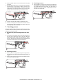
C. Punching process 2
1)
After completion of punching, the transport motor (FRM) and
the bundle exit motor (FAM) are driven to transport paper and
the specified after-process is executed. The motor speed is
300mm/sec for the non-sort mode, and 480mm/sec for the offset mode or the staple mode.
7. Punching process
When the operation mode command is received from the copier,
the finisher makes the finisher operation status command the JOB
and starts the transport operation.
A. Reception of paper discharged from the main
unit
1)
The transport motor (FRM) is driven at the paper exit speed of
the main unit to receive paper from the main unit. When the
paper length is 216mm or less in the offset mode or in the staple mode, the paper exit speed of the second and later sheets
of the same bundle from the main unit is 280mm/sec.
B. Punching process 1
1)
When the paper rear edge passes the paper rear edge sensor,
the transport motor (FRM) is stopped and paper transport is
stopped.
2)
When the paper is stopped, the punch motor (FPNM) is driven
to punch at the paper rear edge.
MX-FNX1/MX-PNX1 OPERATIONAL DESCRIPTIONS 5 – 9
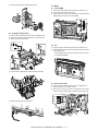
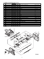
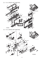
[6] DISASSEMBLY AND
ASSEMBLY
âºíuÇ´
Service Manual
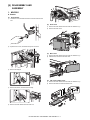
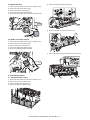
1. MX-FNX1
A. Exterior
(1)
1)
Inner finisher
Loosen the screw, and disconnect the connector from the main
unit.
(2)
2)
Inner cover
1)
Remove the inner finisher from the main unit. Refer to A-(1).
2)
Remove the inner cover.
Open the front cover, and remove the punch unit cover.
2
1
(3)
Rear cover
1)
Remove the inner finisher from the main unit. Refer to A-(1).
2)
Slide the rail, and remove the rear cover.
2
3)
Remove the stopper.
1
(4)
4)
Left cover, bottom cover
1)
Remove the inner finisher from the main unit. Refer to A-(1).
2)
Remove the left cover and the bottom cover.
Remove the screw, and remove the rail stay.
1
5)
Remove the inner finisher from the main unit.
MX-FNX1/MX-PNX1 DISASSEMBLY AND ASSEMBLY 6 – 1
2
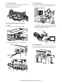
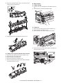
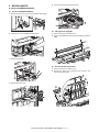
(5)
Reverse guide unit
(2)
Flapper solenoid
1)
Remove the inner finisher from the main unit. Refer to A-(1).
1)
Remove the inner finisher from the main unit. Refer to A-(1).
2)
Remove the inner cover. Refer to A-(2).
2)
Disconnect the connector, and remove the flapper solenoid.
3)
Remove the reverse guide unit.
B. Transport section, paper exit section
(1)
1)
Paddle
* When installing, shift and fix the solenoid so that the reverse
flapper and the cushion material are in contact with each
other with the solenoid plunger pushed in.
Open the front cover, and slide the inner finisher.
2
1
2)
Remove the paddle holders, and remove the paddles.
(3)
Inlet port sensor
1)
Remove the inner finisher from the main unit. Refer to A-(1).
2)
Remove the sensor holder, and remove the inlet port sensor.
MX-FNX1/MX-PNX1 DISASSEMBLY AND ASSEMBLY 6 – 2
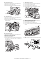
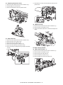
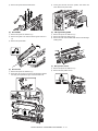
(4)
Roller up/down sensor
(7)
Belt separation solenoid
1)
Remove the inner finisher from the main unit. Refer to A-(1).
1)
Remove the inner finisher from the main unit. Refer to A-(1).
2)
Remove the inner cover. Refer to A-(2).
2)
Remove the inner cover. Refer to A-(2).
3)
Remove the bracket, and remove the roller up/down sensor.
3)
Remove the reverse guide unit. Refer to A-(5).
4)
Remove the parts, and remove the belt separation solenoid.
2
3
1
(5)
Take-up belt sensor
1)
Remove the inner finisher from the main unit. Refer to A-(1).
2)
Remove the inner cover. Refer to A-(2).
3)
Slide the harness guide, remove the bracket, and remove the
take-up belt sensor.
2
(8)
Bundle exit paper transport roller
1)
Remove the inner finisher from the main unit. Refer to A-(1).
2)
Remove the inner cover. Refer to A-(2).
3)
Remove the reverse guide unit. Refer to A-(5).
4)
Remove the parts, and remove the bundle exit paper transport
roller unit.
1
3
2
(6)
1)
Roller up/down motor
1
Remove the inner finisher from the main unit. Refer to A-(1).
2)
Remove the inner cover. Refer to A-(2).
3)
Remove the rear cover. Refer to A-(3).
1
2
4)
Remove the reverse guide unit.
5)
Slide the stapler drive unit. Disconnect the connector from the
PWB. Remove the roller up/down motor unit. Remove the
roller up/down motor.
5)
1
Remove the parts, and remove the bundle exit paper transport
roller.
2
3
3
1
2
MX-FNX1/MX-PNX1 DISASSEMBLY AND ASSEMBLY 6 – 3
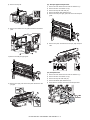
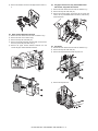
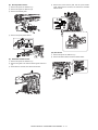
(9)
1)
Take-up belt, paper exit roller
7)
Remove the inner finisher from the main unit. Refer to A-(1).
2)
Remove the inner cover. Refer to A-(2).
3)
Remove the reverse guide unit. Refer to A-(5).
4)
Remove the parts, and remove the bundle roller up/down lever
unit.
Remove the parts, and remove the take-up belt and the paper
exit roller.
3
1
2
2
1
2
1
5)
Remove the parts, and remove the bundle roller unit.
2
2
3
1
1
1
(10) Inlet port gate
6)
Remove the parts, and pull out the belt unit. Remove the parts,
and remove the belt unit.
3
1
1)
Remove the inner finisher from the main unit. Refer to A-(1).
2)
Remove the inner cover. Refer to A-(2).
3)
Remove the left cover and the bottom cover. Refer to A-(4).
4)
Remove the reverse guide unit. Refer to A-(5).
5)
Remove the PWB. Refer to F-(1).
6)
Remove the flapper solenoid. Refer to B-(2).
7)
Remove the slide rail. Remove the slider fixing bracket and
remove the earth terminal.
3
2
1
2
MX-FNX1/MX-PNX1 DISASSEMBLY AND ASSEMBLY 6 – 4
8)
9)
(11) Inlet port paper transport roller
Remove the tray unit.
1)
Remove the inner finisher from the main unit. Refer to A-(1).
2)
Remove the inner cover. Refer to A-(2).
3)
Remove the tray unit. Refer to B-(10).
4)
Remove the bottom plate. Refer to B-(10).
5)
Remove the inlet port upper guide, and remove the transport
guide.
6)
Remove the parts, and remove the inlet port paper transport
roller.
Remove the harness from the guide, and remove the bottom
plate.
4
10) Remove the inlet port upper guide.
1
1
2
3
2
(12) Transport motor
11) Remove the spring, and remove the parts. Remove the inlet
port gate.
1)
Remove the inner finisher from the main unit. Refer to A-(1).
2)
Remove the inner cover. Refer to A-(2).
3)
Remove the tray unit. Refer to B-(10).
4)
Remove the bottom plate. Refer to B-(10).
5)
Disconnect the connector, and remove the transport motor.
1
2
3
3
1
2
MX-FNX1/MX-PNX1 DISASSEMBLY AND ASSEMBLY 6 – 5
(13) Bundle exit motor
5)
1)
Remove the inner finisher from the main unit. Refer to A-(1).
2)
Remove the inner cover. Refer to A-(2).
3)
Remove the tray unit. Refer to B-(10).
4)
Remove the bottom plate. Refer to B-(10).
5)
Disconnect the connector, and remove the bundle exit motor.
Remove the bundle exit paper transport unit.
1
1
1
2
1
3
6)
Remove each parts, and remove the sensor lever.
7)
Remove the center weight, and remove the process tray unit.
2
(14) Paddle one-rotation solenoid
1)
Remove the inner finisher from the main unit. Refer to A-(1).
2)
Remove the inner cover. Refer to A-(2).
3)
Remove the tray unit. Refer to B-(10).
4)
Remove the bottom plate. Refer to B-(10).
5)
Remove the paddle one-rotation solenoid.
1
C. Process tray section
(1)
2
Alignment motors F and R
1)
Remove the inner finisher from the main unit. Refer to A-(1).
2)
Remove the inner cover. Refer to A-(2).
3)
Remove the tray unit. Refer to B-(10).
4)
Remove the load cover. Refer to B-(10).
MX-FNX1/MX-PNX1 DISASSEMBLY AND ASSEMBLY 6 – 6
8)
Remove the alignment plate. Remove the screws and the
pawl, and remove the process tray.
1
D. Staple section
(1)
Staple cartridge
1)
Open the front cover, and slide the inner finisher. Refer to B(1).
2)
Release the lock, and remove the staple cartridge.
2
(2)
9)
Staple unit
1)
Remove the inner finisher from the main unit. Refer to A-(1).
2)
Remove the inner cover. Refer to A-(2).
3)
Remove the latch cover. Remove the parts and the shaft.
Slide the unit and remove the alignment motors F and R.
5
1
4
2
4)
(2)
3
Remove the screw from the bottom. Remove the staple unit,
and disconnect the connector.
1
Empty sensor, alignment plate HP sensors F and R
1)
Remove the inner finisher from the main unit. Refer to A-(1).
2)
Remove the inner cover. Refer to A-(2).
3)
Remove the tray unit. Refer to B-(10).
4)
Remove the process tray unit. Refer to C-(1).
5)
Remove the bracket and the empty sensor. Remove the alignment plate HP sensors F and R.
2
MX-FNX1/MX-PNX1 DISASSEMBLY AND ASSEMBLY 6 – 7
(3)
1)
Alignment plate position sensor
7)
Remove the inner finisher from the main unit. Refer to A-(1).
2)
Shift the staple unit to the front side.
3)
Remove the bracket and remove the position sensor.
(5)
(4)
1)
Disconnect the connector from the PWB, and remove the staple shift motor.
Stapler HP sensor
1)
Remove the inner finisher from the main unit. Refer to A-(1).
2)
Remove the inner cover. Refer to A-(2).
3)
Put the inner finisher upside down, and remove the stapler HP
sensor.
Staple shift motor
Remove the inner finisher from the main unit. Refer to A-(1).
2)
Remove the inner cover. Refer to A-(2).
3)
Remove the rear cover. Refer to A-(3).
4)
Remove the reverse guide unit. Refer to A-(5).
5)
Remove the roller up/down motor. Refer to B-(6).
6)
Remove the E-ring, the flange and the gear pulley, and remove
the gear.
E. Paper exit tray section
(1)
1)
Paper surface sensors 1, 2
Remove the inner finisher from the main unit. Refer to A-(1).
2)
Remove the inner cover. Refer to A-(2).
3)
Remove the tray unit. Refer to B-(10).
4)
Remove the load cover. Refer to C-(1).
5)
Remove the parts, and remove the sensor lever.
MX-FNX1/MX-PNX1 DISASSEMBLY AND ASSEMBLY 6 – 8
6)
(2)
Remove the bracket, and remove the paper surface sensors 1,
2.
(3)
Tray upper limit sensor, tray intermediate lower
limit sensor, tray lower limit sensor
1)
Remove the inner finisher from the main unit. Refer to A-(1).
2)
Remove the tray unit. Refer to B-(10).
3)
Remove the harness guide, and remove the tray upper limit
sensor, the tray intermediate lower limit sensor, and the tray
lower limit sensor.
Paper surface detection solenoid
1)
Remove the inner finisher from the main unit. Refer to A-(1).
2)
Remove the inner cover. Refer to A-(2).
3)
Remove the tray unit. Refer to B-(10).
4)
Remove the bundle exit paper transport roller unit, the sensor
lever, the process tray unit. Refer to C-(1).
5)
Remove the paper surface detection solenoid unit, and
remove the paper surface detection solenoid.
(4)
Tray motor
1)
Remove the inner finisher from the main unit. Refer to A-(1).
2)
Remove the tray unit. Refer to B-(10).
3)
Remove the tray left bracket and the tray drive unit.
4)
Remove the tray drive unit.
MX-FNX1/MX-PNX1 DISASSEMBLY AND ASSEMBLY 6 – 9
5)
F. Others
Remove the gear, and remove the tray motor.
(1)
2
Control PWB
1)
Remove the inner finisher from the main unit. Refer to A-(1).
2)
Remove the rear cover. Refer to A-(3).
3)
Disconnect the connector, and remove the screw. Remove the
PWB support and remove the control PWB.
1
(5)
Tray paper empty sensor
1)
Remove the inner finisher from the main unit. Refer to A-(1).
2)
Remove the left cover and the bottom cover. Refer to A-(4).
3)
Remove the tray bottom cover.
3
3
2
(2)
Fan
1)
Remove the inner finisher from the main unit. Refer to A-(1).
2)
Shift the staple unit to the rear side. Disconnect the connector
and remove the fan.
* When installing, take care that the label of the fan comes to
the direction illustrated.
2
3
2
4)
1
Pull out the tray. Remove the screw, and remove the tray.
(3)
Front cover switch
1)
Remove the inner finisher from the main unit. Refer to A-(1).
2)
Remove the inner cover. Refer to A-(2).
3)
Remove the spring, and remove the interlock sensor lever.
Remove the front cover switch, and disconnect the connector.
1
Yellow
Red
5)
Remove the tray paper empty sensor.
2
Blue
3
4
MX-FNX1/MX-PNX1 DISASSEMBLY AND ASSEMBLY 6 – 10
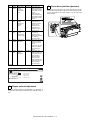
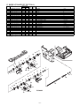
2. MX-PNX1A/B/C/D
5)
Remove the punch unit from the main unit.
A. Punch unit (MX-PNX1A/B/C/D)
(1)
Punch unit (MX-PNX1A/B/C/D)
1)
Remove the coin screw, and remove the finisher slide stopper.
2)
Open the front cover, and slide the inner finisher.
(2)
LED light receiving PWB
1)
Remove the punch unit. Refer to A-(1).
2)
Remove the PWB holder, and remove the LED light receiving
PWB.
2
1
3)
Remove the dust box.
(3)
Punch horizontal resist motor
1)
Remove the punch unit. Refer to A-(1).
2)
Remove the guide cover. Disconnect the connector, and
remove the harness guide.
2
2
4)
Remove the punch cover.
1
3
MX-FNX1/MX-PNX1 DISASSEMBLY AND ASSEMBLY 6 – 11
3)
Remove the punch horizontal resist motor.
3)
Fit the gear hole with the screw position, and remove the
screw. Remove the punch motor.
1
2
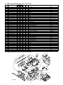
(4)
(6)
Punch PWB
LED light emitting PWB
1)
Remove the punch unit. Refer to A-(1).
1)
Remove the punch unit. Refer to A-(1).
2)
Remove the guide cover and the harness guide. Refer to A(3).
2)
Remove the lower unit. Refer to A-(5).
3)
3)
Remove the punch PWB.
Remove the roller and the PWB holder. Remove the LED light
emitting PWB.
3
2
1
(7)
(5)
Punch motor
1)
Remove the punch unit. Refer to A-(1).
2)
Disconnect the connector, and remove the link plate. Remove
the spring, and separate the upper unit and the lower unit.
Rear position sensor
1)
Remove the punch unit. Refer to A-(1).
2)
Remove the rear position sensor.
1
3
4
2
4
5
4
MX-FNX1/MX-PNX1 DISASSEMBLY AND ASSEMBLY 6 – 12
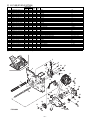
(8)
Punch position sensor
4)
1)
Remove the punch unit. Refer to A-(1).
2)
Remove the upper unit. Refer to A-(5).
3)
Remove the harness guide.
Remove the screws and the pawl, and lift up the harness
guide. Disconnect the connector, and remove the horizontal
shift HP sensor.
3
1
2
4)
Remove the punch position sensor.
(10) Full sensor
(9)
1)
Remove the punch unit. Refer to A-(1).
2)
Remove the drive bracket, and remove the full sensor.
Horizontal shift HP sensor
1)
Remove the punch unit. Refer to A-(1).
2)
Remove the guide cover and the harness guide. Refer to A(3).
3)
Disconnect the connector, and remove the harness.
MX-FNX1/MX-PNX1 DISASSEMBLY AND ASSEMBLY 6 – 13
[7] MAINTENANCE
âºíuÇ´
Service Manual
1. Maintenance system table
✕: Check (Clean, replace, or adjust according to the necessity.) {: Clean S: Replace U: Adjust ✩: Lubricate : Shift position
No.
Part name
When calling
1
2
3
Transport rollers
Transport paper guides
Gears
✕
✕
✕
4
5
6
7
8
9
Belts
Knurling belt
Paddle
Sensors
Discharge brush
Stapler unit
10
Punch unit
11
Staple cartridge
Follows the main unit
cycle.
{
{
✕
✕
✕
{
✕
{
✕
✕
✕
✕
Replacement reference: Replace the unit for every
200K stapling.
Replacement reference: Replace the unit for every
1000K punching.
User replacement for every use of 5,000 pcs.
Remark
Replacement reference: Finisher count value of 1000K.
1
1
1
1
1
1
7
7
7
7
7
7
7
7
7
7
7
7
7
7
7
7
7
7
7
7
7
10
8
6
5
6
6
8
6
8
9
6
11
6
5
MX-FNX1/MX-PNX1 MAINTENANCE 7 – 1
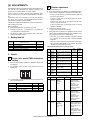
[8] ADJUSTMENTS
âºíuÇ´
Each adjustment item in the adjustment item list is identified with its
own JOB No. The adjustments are basically executed in the
sequence from a smaller JOB No. to a larger JOB No.
Service Manual
2 Finisher adjustment
1)
Enter Simulation 3-10.
2)
Select a set item with [↑] [↓] buttons. The highlighted section of
the set value is changed and is displayed on the setting area.
There is, however, no need to perform all the adjustment items.
Only the necessary items may be executed depending on the situation.
* If there is any item over [↑], the display becomes active and
the cursor can be moved.
Unnecessary items may be skipped to go to the next necessary
item. In this case, of course, the adjustment sequence could be
executed from a smaller to a larger JOB No.
If there is no item over [↑], the display grays out and the
operation is disabled.
If there is any item under [↓], the display becomes active
and the cursor can be moved.
If the above is neglected, the adjustment cannot be completed normally, resulting in a trouble.
If there is no item under [↓], the display grays out and the
operation is disabled.
[Start of simulation]
1)
Press [COPY MODE] key to enter the copy mode.
3)
Enter the set value with 10-key.
2)
Press [P] (Program) key → [*] (Asterisk) key → [C] (Clear) key
→ [*] (Asterisk) key in this sequence.
4)
When [OK] button is pressed, it is highlighted and the entered
value is saved to EEPROM and RAM. After completion of setting, [OK] button returns to the normal display.
3)
* Press [C] key to clear the entered value.
The display is shifted to the simulation main number entry
screen (entry standby screen).
* When [OK], [↑], [↓] button, [COLOR], or [BLACK & WHITE]
key is pressed, the current set value is saved to EEPROM
and RAM.
1. Setting item list
JOB No.
1
2
3
4
Simulation
to be used
–
3-10
–
–
Adjustment item list
Punch unit, punch PWB destination setting
Finisher adjustment
Flapper solenoid adjustment
Punch home position adjustment
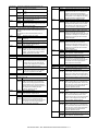
2. Details
* When the reset key is pressed, the simulation is terminated.
* When [SYSTEM SETTINGS] key is pressed, the display
returns to the sub number entry screen.
<Set range and default value of each set value>
Item
Display
Item
A
FRONT
ADJUST
REAR
ADJUST
STAPLE
REAR
STAPLE
FRONT
STAPLE
BOTH
STAPLE
PITCH
PUNCH
CENTER
PUNCH
HOLE
Alignment position adjustment
(Front)
Alignment position adjustment
(Rear)
Staple binding position
adjustment (One position, rear)
Staple binding position
adjustment (One position, front)
Staple binding position
adjustment (2 positions, center)
Staple binding position (2
positions, pitch)
Punch center adjustment
B
1 Punch unit, punch PWB destination
setting
C
D
1)
When the punch PWB is replaced, the destination setting must
be performed.
E
2)
For destination setting, the DIP switch (SW1) on the punch
PWB is used.
F
G
㪦㪥
㪈
3)
H
Kind of punching
2-hole type
2/3-hole type
4-hole type (France)
4-hole type (Sweden)
Default
value
10
2 to 18
10
68 to 132
100
68 to 132
100
68 to 132
100
68 to 132
100
37 to 63
50
42 to 58
50
<Variation and change direction of each set value>
㪉
The relationship between the switches and the destinations is
shown in the table below.
Model
MX-PNX1A
MX-PNX1B
MX-PNX1C
MX-PNX1D
Punch hole position adjustment
Set
range
2 to 18
1
OFF
ON
OFF
ON
2
OFF
OFF
ON
ON
Item
A
Display
FRONT
ADJUST
Item
Alignment
position
adjustment
(Front)
Variation
0.3665mm
B
REAR
ADJUST
Alignment
position
adjustment
(Rear)
0.3665mm
C
STAPLE
REAR
Staple binding
position
adjustment
(One position,
rear)
0.155mm
MX-FNX1/MX-PNX1 ADJUSTMENTS 8 – 1
Change direction
Large value: The
alignment plate
position is shifted to
the center.
Small value: The
alignment plate
position is shifted to
the outside.
Large value: The
alignment plate
position is shifted to
the center.
Small value: The
alignment plate
position is shifted to
the outside.
Large value: The
distance between the
staple position and the
paper edge becomes
shorter.
Small value: The
distance between the
staple position and the
paper edge becomes
longer.
Item
D
Display
STAPLE
FRONT
Item
Staple binding
position
adjustment
(One position,
front)
Variation
0.155mm
E
STAPLE
BOTH
Staple binding
position
adjustment (2
positions,
center)
0.155mm
F
STAPLE
PITCH
Staple binding
position
adjustment (2
positions, pitch)
0.155mm
G
PUNCH
CENTER
Punch center
adjustment
0.1441mm
H
PUNCH
HOLE
Punch hole
position
adjustment
0.2584mm
Change direction
Large value: The
distance between the
staple position and the
paper edge becomes
longer.
Small value: The
distance between the
staple position and the
paper edge becomes
shorter.
Large value: The
staple position is
shifted to the bottom
from the center.
Small value: The
staple position is
shifted to the front
from the center.
Large value: The pitch
of 2 positions
becomes greater.
Small value: The pitch
of 2 positions
becomes smaller.
Large value: The hole
position is shifted to
the bottom from the
center.
Small value: The hole
position is shifted to
the front from the
center.
Large value: The
distance between the
hole position and the
paper rear edge
becomes shorter.
Small value: The
distance between the
hole position and the
paper rear edge
becomes longer.
4 Punch home position adjustment
In case the punch unit comes out of order and does not function,
turn the dial to make the punch align to the home position. By making the punch align to the home position, only the paper feed
comes possible.
[Screen]
0
TEST
FINISHER ADJUSTMENT
A: 10
B: 10
10
A:
; FRONT ADJUST
; REAR ADJUST
C:100
D:100
; STAPLE REAR
; STAPLE FRONT
[
CLOSE
SIMULATION NO.03-10
2~ 18 ]
OK
3 Flapper solenoid adjustment
When the flapper solenoid is disassembled, an adjustment is
required when assembling. (Disassembly and assembly: Refer to
6-2.)
MX-FNX1/MX-PNX1 ADJUSTMENTS 8 – 2
HOME
[9] SELF DIAGNOSTICS AND
TROUBLE CODES
âºíuÇ´
1. Trouble code and troubleshooting
Service Manual
Phenomenon
Case 1
A. MX-FNX1
Phenomenon
Case 1
Case 2
Case 3
Case 4
Phenomenon
Case 1
Case 2
Case 3
Phenomenon
Case 1
Case 2
Case 3
Though the main switch of the main unit is turned ON, the
inner finisher does not operate. Trouble code: F1-00
Cause
Connection failure with the main unit.
Check & Check to confirm the connection state of the
Remedy connectors.
Cause
Connection failure of the connector contact pin
(interface harness) with the main unit.
Check & Check to confirm the conduction state of the
Remedy connectors. If there is no conduction, replace
the connection wire.
Cause
Front cover switch (FDSW) trouble
Check & Check to confirm the conduction state of the
Remedy connectors. If there is no conduction, replace
the connection wire.
Cause
Control PWB trouble
Check & After checking the above 1 to 3, if DC24V and
Remedy DV5V are not supplied from the main unit and
if 24V is not supplied to TP14 and 5V is not
supplied to TP17, replace the control PWB.
The transport motor (FRM) does not operate.
The bundle exit motor (FAM) does not operate.
Cause
Motor connector pin contact failure
Check & Check the connection state of the connector.
Remedy (CN14)
Cause
Motor coil disconnection
Check & Perform the conduction test of the coil. If there
Remedy is no conduction, replace the motor.
Cause
Control PWB trouble
Check & If the motor does not operate in the motor
Remedy single operation mode, replace the control
PWB.
Roller up/down motor (FSWM) does not operate. Trouble
code: F1-03
Cause
Roller up/down sensor (FRLD) trouble
Check & Measure the voltage of TP12 on the control
Remedy PWB to confirm that it is 5V±5% when the
paper exit roller descends, and 1V or less
when the paper exit roller rises. If the voltage
does not satisfy the said condition, replace the
sensor.
Cause
Motor coil disconnection
Check & Perform the conduction test of the coil. If there
Remedy is no conduction, replace the motor.
Cause
Control PWB trouble
Check & After checking the above 1 and 2, if the
Remedy phenomenon is not removed though the
sensor level is changed and if the motor does
not operate in the motor single operation
mode, replace the control PWB.
Case 2
Case 3
Case 4
Phenomenon
Case 1
Case 2
Case 3
Case 4
Phenomenon
Case 1
Case 2
The alignment motor F (FFJM) does not operate.
Trouble code: F1-19
The alignment motor R (FRJM) does not operate.
Trouble code: F1-20
Cause
Alignment plate HP sensor F (FFJHPD)
trouble
Check & Measure the voltage of TP9 on the control
Remedy PWB to confirm that it is 5V±5% when the
alignment plate is pushing against the center
portion, and is 1V or less when the alignment
plate is pushing against the front side (home
position). If the voltage does not satisfy the
above condition, replace the sensor.
Cause
Alignment plate HP sensor R (FRJHPD)
trouble
Check & Measure the voltage of TP10 on the control
Remedy PWB to confirm that it is 5V±5% when the
alignment plate is pushing against the center
portion, and is 1V or less when the alignment
plate is pushing against the rear side (home
position). If the voltage does not satisfy the
above condition, replace the sensor.
Cause
Motor coil disconnection
Check & Perform the conduction test of the coil. If there
Remedy is no conduction, replace the coil.
Cause
Control PWB trouble
Check & After checking the above 1 to 3, if the
Remedy phenomenon is not removed though the
sensor level is changed and if the motor does
not operated in the motor single operation
mode, replace the control PWB.
A paper jam error is displayed on the system display.
Cause
Paper jam
Check & Visually check and remove the paper jam
Remedy
Cause
Inlet port sensor (FED) trouble
Check & Measure the voltage of TP11 on the control
Remedy PWB to confirm that it is 1V or less when
paper is empty, and is 5V±5% when paper is
provided. If the voltage does not satisfy the
above condition, replace the sensor.
Cause
Empty sensor (FSTPD) trouble
Check & Measure the voltage of TP8 on the control
Remedy PWB to confirm that it is 1V or less when
paper is empty, and is 5V±5% when paper is
provided. If the voltage does not satisfy the
above condition, replace the sensor.
Cause
Control PWB trouble
Check & If the phenomenon is not removed though the
Remedy sensor level is changed by turning ON/OFF
each sensor, replace the control PWB.
A document is not detected.
Cause
Tray paper empty sensor (FBED) trouble
Check & Measure the voltage of TP4 on the control
Remedy PWB to confirm that it is 5V±5% when paper is
empty, and is 1V or less when paper is
provided. If the voltage does not satisfy the
above condition, replace the sensor.
Cause
Control PWB trouble
Check & If the phenomenon is not removed though the
Remedy sensor level is changed by turning ON/OFF
each sensor, replace the control PWB.
MX-FNX1/MX-PNX1 SELF DIAGNOSTICS AND TROUBLE CODES 9 – 1
Phenomenon
Case 1
Case 2
Case 3
Phenomenon
Case 1
Case 2
Case 3
A document is discharged to the reverse path in the
operation other than reverse operation.
Cause
Flapper solenoid (FINRPS) connector pin
trouble
Check & Check the connection state of the connector.
Remedy (CN15)
Cause
Solenoid coil disconnection
Check & Perform the conduction test of the coil. If there
Remedy is no conduction, replace the coil.
Cause
Control PWB trouble
Check & If the flapper solenoid (FINRPS) does not
Remedy operate in the solenoid single operation mode,
replace the control PWB.
The belt separation solenoid (FBRS) does not operate.
The paper surface detection solenoid (FSLS) does not
operate
The paddle one-rotation solenoid (FPDS) does not
operate.
Cause
Solenoid connector pin trouble
Check & Check the connection state of the connector.
Remedy (CN15, 20)
Cause
Solenoid coil disconnection
Check & Perform the conduction test of the coil. If there
Remedy is no conduction, replace the coil.
Cause
Control PWB trouble
Check & If the solenoid does not operate in the single
Remedy operation mode of the belt separation solenoid
(FBRS), the paper surface detection solenoid
(FSLS), or the paddle one-rotation solenoid
(FPDS), replace the control PWB.
Phenomenon
Case 1
Case 2
Case 3
Case 4
Case 5
Case 6
Phenomenon
Case 1
Case 2
Phenomenon
Case 1
Case 2
Case 3
The take-up belt does not operate normally.
Cause
Take-up belt sensor (FBRD) trouble
Check & Measure the voltage of TP13 on the control
Remedy PWB to confirm that it is 5V±5% when the belt
descends, and is 1V or less when the belt
separates. If the voltage does not satisfy the
above condition, replace the sensor.
Cause
Control PWB trouble
Check & If the phenomenon is not removed though the
Remedy sensor level is changed by turning ON/OFF
each sensor, replace the control PWB.
The staple shift motor does not operate.
Trouble code: F1-08
Cause
Stapler HP sensor (FSTHPD) trouble
Check & Measure the voltage of TP7 on the control
Remedy PWB to confirm that it is 5V±5% when the
stapler unit is pushing against the front side
(home position), and is 1V or less when the
stapler unit is pushing against the rear side. If
the voltage does not satisfy the above
condition, replace the sensor.
Cause
Motor coil disconnection
Check & Perform the conduction test of the coil. If there
Remedy is no conduction, replace the coil.
Cause
Control PWB trouble
Check & After checking the above 1 to 2, if the
Remedy phenomenon is not removed though the
sensor level is changed and if the motor does
not operate in the motor single operation
mode, replace the control PWB.
Phenomenon
Case 1
Case 2
Case 3
Case 4
Case 5
The stapler does not operate. Trouble code: F1-10
Cause
Alignment plate position sensor (FJPD) trouble
Check & Measure the voltage of TP50 on the control
Remedy PWB to confirm that it is 1V or less when the
stapler is at the paper rear edge stopper
section, and is 5V±5% when the stapler is not
at that position. If the voltage does not satisfy
the above condition, replace the sensor.
Cause
Stapler home sensor (FSHPD) trouble
Check & Measure the voltage of TP51 on the control
Remedy PWB to confirm that it is 5V±5% at the stapling
mechanism home position, and is 1V or less
when stapling. If the voltage does not satisfy
the above condition, replace the stapler.
Cause
Self priming sensor (FSTD) trouble
Check & Measure the voltage of TP52 on the control
Remedy PWB to confirm that it is 5V±5% when a
cartridge is provided (READY state), and is 1V
or less when a cartridge is not provided. If the
voltage does not satisfy the above condition,
replace the stapler.
Cause
Staple empty sensor (FSD) trouble
Check & Measure the voltage of TP53 on the control
Remedy PWB to confirm that it is 5V±5% when a
cartridge is provided (with staples), and is 1V
or less when a cartridge is not provided. If the
voltage does not satisfy the above condition,
replace the stapler.
Cause
Motor coil disconnection
Check & Perform the conduction test of the coil. If there
Remedy is no conduction, replace the stapler.
Cause
Control PWB trouble
Check & After checking the above 1 to 5, if the
Remedy phenomenon is not removed though the
sensor level is changed and if the motor does
not operate in the motor single operation
mode, replace the control PWB.
The tray does not operate. Trouble code: F1-15
Cause
The paper surface sensor 1 (FSLD1), paper
surface sensor 2 (FSLD2) trouble
Check & Measure the voltage of TP5 and 6 on the
Remedy control PWB to confirm that it is changed in the
range of 1V or less to 5V±5% when the paper
holding lever is moved. If the voltage does not
satisfy the above condition, replace the sensor.
Cause
Tray upper limit sensor (FULD) trouble
Check & Measure the voltage of TP1 on the control
Remedy PWB to confirm that it is 1V or less when the
tray is at the upper limit position, and is 5V±5%
when the tray is not at the upper limit position.
If the voltage does not satisfy the above
condition, replace the sensor.
Cause
Tray intermediate lower limit sensor (FMLLD)
trouble
Check & Measure the voltage of TP2 on the control
Remedy PWB to confirm that it is 1V or less when the
tray is at the intermediate position, and is
5V±5% when the tray is not at the intermediate
position. If the voltage does not satisfy the
above condition, replace the sensor.
Cause
Tray lower limit sensor (FLLD) trouble
Check & Measure the voltage of TP3 on the control
Remedy PWB to confirm that it is 1V or less when the
tray is at the lower limit position, and is 5V±5%
when the tray is not at the lower limit position.
If the voltage does not satisfy the above
condition, replace the sensor.
Cause
Motor coil disconnection
Check & Perform the conduction test of the coil. If there
Remedy is no conduction, replace the stapler.
MX-FNX1/MX-PNX1 SELF DIAGNOSTICS AND TROUBLE CODES 9 – 2
Case 6
Cause
Check &
Remedy
Phenomenon
Case 1
Case 2
Case 3
Case 4
Cause
Check &
Remedy
Cause
Check &
Remedy
Cause
Check &
Remedy
Cause
Check &
Remedy
Control PWB trouble
After checking the above 1 to 5, if the
phenomenon is not removed though the
sensor level is changed and if the motor does
not operate in the motor single operation
mode, replace the control PWB.
The fan (FFAN) does not operate. Trouble code: F121
Pinching of a foreign material
Visually check to remove a foreign material from the
inlet port.
Motor coil disconnection
Perform the conduction test of the coil. If there is no
conduction, replace the motor.
Lock detection trouble
Measure the voltage of TP88 on the control PWB to
confirm that it is 1V or less when lock is released,
and is 5V±5% when lock is set. If the voltage does
not satisfy the above condition, replace it.
Control PWB trouble
After checking the above 1 to 3, if the fan (FFAN)
does not operate in the motor single operation mode,
replace the control PWB.
Phenomenon
Case 1
Cause
Check &
Remedy
Case 2
Cause
Check &
Remedy
Cause
Check &
Remedy
Case 3
Phenomenon
Case 1 Cause
Check &
Remedy
B. MX-PNX1A/B/C/D
Phenomenon
Case 1
Case 2
Cause
Check &
Remedy
Cause
Check &
Remedy
Though the main switch of the main unit is turned
ON, the inner punch does not operate at all.
Connection failure with the inner finisher
Check to confirm that each connector is connected
properly.
Connection failure of the drawer connector with the
inner finisher
Check the conduction state of the connector pins as
well as the inner finisher. If there is no conduction,
replace the drawer connector.
Control PWB trouble
After checking the above 1 and 2, if DC24V and
DC5V are not supplied from the main unit or if 24V is
not output to TP19 and 5V is not output to TP22 on
the control PWB, replace the control PWB.
Case 3
Cause
Check &
Remedy
Pheno
menon
Case 1
The punch motor (FPNM) does not operate.
Trouble code: F1-34
Cause
Punch position sensor (FPHPD) trouble
Check & Measure the voltage of TP47 on the inner finisher
Remedy control PWB to confirm that it is 5V±5% at the home
position, and is 1V or less when punching. If the
voltage does not satisfy the above condition, replace
the sensor.
Cause
Rear position sensor (FPRPD) trouble
Check & Measure the voltage of TP48 on the inner finisher
Remedy control PWB to confirm that it is 5V±5% at the lower
limit position, and is 1V or less at the upper limit
position. If the voltage does not satisfy the above
condition, replace the sensor.
Cause
Motor coil disconnection
Check & Perform the conduction test of the coil. If there is no
Remedy conduction, replace the coil.
Cause
Control PWB trouble
Check & After checking the above 1 to 3, if the phenomenon
Remedy is not removed though the sensor level is changed
and if the motor does not operate in the motor single
operation mode, replace the control PWB.
Case 2
Case 3
Case 4
Case 2
Cause
Check &
Remedy
Phenomenon
Case 1 Cause
Check &
Remedy
Case 2 Cause
Check &
Remedy
Case 3
Cause
Check &
Remedy
Case 4
Cause
Check &
Remedy
Punch horizontal resist motor (FPSM) does not
operate. Trouble code: F1-33
Horizontal shift HP sensor (FPSHPD) trouble
Measure the voltage of TP49 on the inner finisher
control PWB to confirm that it is 5V±5% at the home
position, and is 1V or less at the upper limit position.
If the voltage does not satisfy the above condition,
replace the sensor.
Motor coil disconnection
Perform the conduction test of the coil. If there is no
conduction, replace the coil.
Control PWB trouble
After checking the above 1 and 2, if the
phenomenon is not removed though the sensor level
is changed and if the motor does not operate in the
motor single operation mode, replace the control
PWB.
The punch dust container full is not detected.
Full sensor (FPDD) trouble
If there is no punch dust in the punch dust container,
measure the voltage of TP2 on the control PWB to
confirm that it is 5V±5% when the punch dust
container is removed, and is 1V or less when the
lever in the punch dust container is put straight and
stored (the sensor is shaded from the light). It the
voltage does not satisfy the above condition, replace
the sensor.
Control PWB trouble
If the phenomenon is not removed though the
sensor level is changed by turning ON/OFF the
sensor, replace the control PWB.
A paper jam error is displayed on the system display.
Paper jam
Visually check and remove the paper jam.
Paper rear edge sensor (FPPEND) trouble
Measure the voltage of TP54 on the inner finisher
control PWB to confirm that it is 1.05V or less when
paper is supplied, and is 2.88V or more when paper
is empty. If the voltage does not satisfy the above
condition, replace the sensor PWB (LED, PTR).
Paper horizontal resist sensor (FPPD1 to 6) trouble
Measure the voltage of TP55 on the inner finisher
control PWB to confirm that it is 1.05V or less when
paper is supplied, and is 2.88V or more when paper
is empty. If the voltage does not satisfy the above
condition, replace the sensor PWB (LED, PTR).
Control PWB trouble
If the phenomenon is not removed though the
sensor level is changed by turning ON/OFF the
sensor, replace the control PWB.
MX-FNX1/MX-PNX1 SELF DIAGNOSTICS AND TROUBLE CODES 9 – 3
âºíuÇ´
[10]
ELECTRICAL SECTION
2) Tray intermediate
Service
Manuallower limit sensor (FMLLD)
The tray intermediate lower limit sensor (FMLLD) employs the
photo interrupter in which the light emitting diode and the
photo transistor are integrated.
1. Circuit descriptions
The lower limit is detected by interruption of lights with the
light-shielding plate.
A. MX-FNX1
(1)
General
Signals are inputted to the multiplexer (IC14-14pin) through
the noise filter of R12 and C2.
This circuit controls transport, alignment (bundle alignment), staple,
and exit of paper discharged from the main unit.
The logic of the signal inputted to the CPU is L for the tray
intermediate position.
This circuit is composed of sensors, switches, the circuit which processes signals from the main unit, the circuit which drives motors
and solenoids, the CPU, and its peripheral circuits.
(2)
Circuit descriptions
R2 is the current-limiting resistor of the light emitting diode. R7
is the load resistor of the sensor.
3)
Tray lower limit sensor (FLLD)
The tray lower limit sensor (FLLD) employs the photo interrupter in which the light emitting diode and the photo transistor
are integrated.
a. Communication circuit
The lower limit is detected by interruption of lights with the
light-shielding plate.
Signals are inputted to the multiplexer (IC14-15pin) through
the noise filter of R13 and C3.
The logic of the signal inputted to the CPU is L for the tray
lower limit position.
R3 is the current-limiting resistor of the light emitting diode. R8
is the load resistor of the sensor.
Tray paper empty sensor (FBED)
4)
Tray paper empty sensor (FBED)
The tray empty sensor (FBED) employs the photo interrupter
in which the light emitting diode and the photo transistor are
integrated.
Paper empty is detected by interruption of lights with the levertype actuator.
Signals are inputted to the CPU (IC10-74pin) through the noise
filter of R14 and C4.
The logic of the signal inputted to the CPU is L when paper is
loaded to the tray, and H for paper empty.
This circuit is the communication circuit with the main unit.
TxD and DTR are data to be sent from the main unit to the inner finisher. RxD and DSR are data to be sent from the inner finisher to
the main unit. The reset signal from the main unit is inputted to
RESET.
R4 is the current-limiting resistor of the light emitting diode. R9
is the load resistor of the sensor.
Paper surface detection sensor 1
(FSLD1)
b. Sensor input circuit
Tray upper limit sensor (FULD)
Paper surface detection sensor 2
(FSLD2)
Tray intermediate lower limit sensor
(FMLLD)
Tray lower limit sensor (FLLD)
5)
1)
Paper surface sensor 1 (FSLD1)
The paper surface sensor 1 (FSLD1) employs the photo interrupter in which the light emitting diode and the photo transistor
are integrated.
Tray upper limit sensor (FULD)
The tray upper limit sensor (FULD) employs the photo interrupter in which the light emitting diode and the photo transistor
are integrated.
The paper surface is detected by interruption of lights with the
lever-type actuator.
The upper limit is detected by interruption of lights with the
light-shielding plate.
By use of Q16, the logic of signal when the connector is disconnected is made the same as when light is emitted to the
sensor.
Signals are inputted to the multiplexer (IC14-13pin) through
the noise filter of R11 and C1.
Signals are inputted to the CPU (IC10-88pin) through the noise
filter of R17 and C5.
The logic of the signal inputted to the CPU is L for the tray
upper limit position.
The logic of the signal inputted to the CPU is H when light is
interrupted, and L when light is emitted to the sensor.
R1 is the current-limiting resistor of the light emitting diode. R6
is the load resistor of the sensor.
R5 is the current-limiting resistor of the light emitting diode.
R15 is the load resistor of the sensor.
MX-FNX1/MX-PNX1 ELECTRICAL SECTION 10 – 1
6)
Paper surface sensor 2 (FSLD2)
The paper surface sensor 2 (FSLD2) employs the photo interrupter in which the light emitting diode and the photo transistor
are integrated.
The paper surface is detected by interruption of lights with the
lever-type actuator.
The logic of the signal inputted to the CPU is L at the front side
alignment guide home position.
R21 is the current-limiting resistor of the light emitting diode.
R25 is the load resistor of the sensor.
10) Alignment plate HP sensor R (FRJHPD)
Signals are inputted to the CPU (IC10-89pin) through the noise
filter of R18 and C6.
The alignment plate HP sensor R (FRJHPD) employs the
photo interrupter in which the light emitting diode and the
photo transistor are integrated.
The logic of the signal inputted to the CPU is H when light is
interrupted, and L when light is emitted to the sensor.
The home position is detected by interruption of lights with the
actuator of the light-shielding plate.
R10 is the current-limiting resistor of the light emitting diode.
R16 is the load resistor of the sensor.
Signals are inputted to the CPU (IC10-58pin) through the noise
filter of R30 and C10.
The logic of the signal inputted to the CPU is L at the rear side
alignment guide home position.
Stapler HP sensor (FSTHPD)
R22 is the current-limiting resistor of the light emitting diode.
R26 is the load resistor of the sensor.
7)
Inlet port sensor (FED)
Stapler HP sensor (FSTHPD)
Stapler HP sensor (FSTHPD) employs the photo interrupter in
which the light emitting diode and the photo transistor are integrated.
Roller up/down sensor (FRLD)
The home position is detected by interruption of lights with the
actuator of the light-shielding plate.
Take-up belt sensor (FBRD)
Signals are inputted to the CPU (IC10-18pin) through the noise
filter of R27 and C7.
The logic of the signal inputted to the CPU is H at the stapler
unit home position.
R19 is the current-limiting resistor of the light emitting diode.
R23 is the load resistor of the sensor.
Empty sensor (FSTPD)
11) Inlet port sensor (FED)
The inlet port sensor (FED) employs the photo interrupter in
which the light emitting diode and the photo transistor are integrated.
The inlet port is detected by interruption of lights with the levertype actuator.
Signals are inputted to the CPU (IC10-71pin) through the noise
filter of R37 and C11.
The logic of the signal inputted to the CPU is H when paper is
provided, and L when paper is not provided.
Alignment plate HP sensor F
(FFJHPD)
R31 is the current-limiting resistor of the light emitting diode.
R34 is the load resistor of the sensor.
Alignment plate HP sensor R
(FRJHPD)
12) Roller up/down sensor (FRLD)
The roller up/down sensor (FRLD) employs the photo interrupter in which the light emitting diode and the photo transistor
are integrated.
8)
Empty sensor (FSTPD)
The empty sensor (FSTPD) employs the photo interrupter in
which the light emitting diode and the photo transistor are integrated.
Signals are inputted to the CPU (IC10-59pin) through the noise
filter of R38 and C12.
Paper empty is detected by interruption of lights with the levertype actuator.
The logic of the signal inputted to the CPU is L when the roller
is at the upper standby position.
By use of Q16, the logic of signal when the connector is disconnected is made the same as when light is emitted to the
sensor (paper empty).
R32 is the current-limiting resistor of the light emitting diode.
R35 is the load resistor of the sensor.
Signals are inputted to the CPU (IC10-90pin) through the noise
filter of R28 and C8.
The logic of the signal inputted to the CPU is H when paper is
provided in the process tray, and L when paper is not provided.
R20 is the current-limiting resistor of the light emitting diode.
R24 is the load resistor of the sensor.
9)
The roller up/down is detected by interruption of lights with the
lever-type actuator.
13) Take-up belt sensor (FBRD)
The take-up belt sensor (FBRD) employs the photo interrupter
in which the light emitting diode and the photo transistor are
integrated.
The take-up belt is detected by interruption of lights with the
lever-type actuator.
Alignment plate HP sensor F (FFJHPD)
Signals are inputted to the CPU (IC10-61pin) through the noise
filter of R39 and C50.
The alignment plate HP sensor F (FFJHPD) employs the photo
interrupter in which the light emitting diode and the photo transistor are integrated.
The logic of the signal inputted to the CPU is L when the takeup belt is on the upper side.
The home position is detected by interruption of lights with the
actuator of the light-shielding plate.
R33 is the current-limiting resistor of the light emitting diode.
R36 is the load resistor of the sensor.
Signals are inputted to the CPU (IC10-57pin) through the noise
filter of R29 and C9.
MX-FNX1/MX-PNX1 ELECTRICAL SECTION 10 – 2
16) Self priming sensor (FSTD)
Stapler
Alignment plate position sensor
(FJPD)
The self priming sensor (FSTD) is the built-in sensor of the stapler unit.
Self priming is detected by the open-collector output with the
circuit in the unit.
Stapler home sensor
(FSHPD)
Signals are inputted to the multi-plexer (IC14-5pin) through the
noise filter of RA4.2 and C60.
The logic of the signal inputted to the CPU is H in the READY
state.
17) Staple empty sensor (FSD)
14) Alignment plate position sensor (FJPD)
The alignment plate position sensor (FJPD) employs the photo
interrupter in which the light emitting diode and the photo transistor are integrated.
The staple empty sensor (FSD) is the built-in sensor of the stapler unit.
Staple empty is detected by the open-collector output with the
circuit in the unit.
The alignment plate position is detected by interruption of
lights with the lever-type actuator.
Signals are inputted to the multi-plexer (IC14-2pin) through the
noise filter of RA4.3 and C61.
Signals are inputted to the multi-plexer (IC14-12pin) through
the noise filter of RA4.1 and C58.
The logic of the signal inputted to the CPU is L in case of staple empty.
The logic of the signal inputted to the CPU is L when the paper
rear edge stopper is provided at the opening of the stapler.
18) Front cover switch (FDSW)
R103 is the current-limiting resistor of the light emitting diode.
R104 is the load resistor of the sensor.
15) Stapler home sensor (FSHPD)
The stapler home sensor (FSHPD) is the built-in sensor of the
stapler unit.
The home position is detected by the open-collector output
with the circuit in the unit.
Signals are inputted to the multi-plexer (IC14-1pin) through the
noise filter of RA4.4 and C59.
The logic of the signal inputted to the CPU is H at the stapler
mechanism home position.
The front cover switch (FDSW) employs a micro switch to
detect open/close of the front cover.
This switch is provided with +24V. By opening the open/close
section, the contact is opened to function as a switch.
When the switch is turned ON, +24V is applied to the cathode
of ZD2, supplying a base current to Q2 to turn ON Q2. Then
open/close signal is inputted to the CPU (IC10-19pin). This
signal is commonly used with the inner punch +5V supply signal.
The logic of the signal inputted to the CPU is H when the front
cover is open, and L when the front cover is close.
c. Motor drive circuit
1)
Transport motor (FRM) drive circuit
Transport motor
(FRM)
Not installed
This circuit controls rotation, stop, rotating direction, and current of the transport motor (FRM), and is composed of the CPU (IC10), the DA
converter (IC11), and the constant-current chopper system driver IC (IC5). The motor rotating speed is controlled with the stepping motor
drive signal (R_MOT_CLK) outputted from the CPU (IC10-22pin), and the motor rotating direction is controlled with the signal
(R_MOT_CW/CCW) outputted from the CPU (IC10-21pin).
The analog signal (R_MOT_REF) outputted from the DA converter (IC11-3pin) is divided into a certain voltage with R70 and R71. The
divided voltage is inputted to IC5-7pin to set the motor current value.
MX-FNX1/MX-PNX1 ELECTRICAL SECTION 10 – 3
2)
Bundle exit motor (FAM) drive circuit
This circuit controls rotation/stop rotating direction and current of the bundle exit motor (FAM), and is composed of the CPU (IC10), the DA
converter (IC11), and the constant-current chopper system driver IC (IC8). The motor rotating speed and the rotting direction are controlled
with the stepping motor drive excitement pattern signal (T_MOT_A, *A, B, *B) outputted from the CPU (IC10-79, 80, 81, 82pin).
The analog signal (T_MOT_REF) outputted from the DA converter (IC11-5pin) is divided into a certain voltage with R74 and R75. The
divided voltage is inputted to IC8-3, 14 pin to set the motor current value.
Bundle exit motor (FAM)
Not installed
3)
Roller up/down motor (FSWM) drive circuit
This circuit controls rotation/stop and the rotating direction of the roller up/down motor (FSWM) and the motor current, and is composed of
the CPU (IC10), the DA converter (IC11), and the constant-current chopper system driver IC (IC16). The motor rotating speed and the
rotating direction are controlled with the stepping motor drive excitement pattern signal (RO_MOT_A, *A, B, *B) outputted from the CPU
(IC10-75, 76, 77, 78pin).
The analog signal (RO_MOT_REF) outputted from the DA converter (IC11-4pin) is divided into a certain voltage with R90 and R114. The
divided voltage is inputted to IC16-3, 14pin to set the motor current value.
Roller up/down motor (FSWM)
Not installed
4)
Staple shift motor (FSM) drive circuit
Staple shift motor (FSM)
Not installed
MX-FNX1/MX-PNX1 ELECTRICAL SECTION 10 – 4
This circuit controls rotation/stop and the rotating direction of the staple shift motor (FSM) and the motor current, and is composed of the
CPU (IC10), the DA converter (IC11), and the constant-current chopper system driver IC (IC4). The motor rotating speed and the rotating
direction are controlled with the stepping motor drive excitement pattern signal (ST_MOT_PA, PB, EA, EB) outputted from the CPU (IC1045, 46, 47, 48pin).
The analog signal (ST_MOT_REF) outputted from the DA converter (IC11-18pin) is divided into a certain voltage with R64 and R65. The
divided voltage is inputted to IC4-3, 4pin to set the motor current value. The logic of the standby signal (MOT_STY) outputted from the DA
converter (IC11-7pin) is H when the motor can be operated (READY).
5)
Alignment motor F (FFJM) drive circuit
6)
Alignment motor R (FRJM) drive circuit
Alignment motor F (FFJM)
Not
installed
Alignment motor R (FRJM)
Not installed
This circuit controls rotation/stop and the rotating direction of the alignment motor F (FFJM) and the motor current, and is composed of the
CPU (IC10), the DA converter (IC11), and the constant-current chopper system driver IC (IC17). The motor rotating speed and the rotating
direction are controlled with the stepping motor drive excitement pattern signal (J1_MOT_PA, PB, EA, EB) outputted from the CPU (IC1049, 50, 51, 52pin).
The analog signal (J1_MOT_REF) outputted from the DA converter (IC11-19pin) is divided into a certain voltage with R125 and R126. The
divided voltage is inputted to IC17-3, 4pin to set the motor current value. The logic of the standby signal (MOT_STY) outputted from the
DA converter (IC11-7pin) is H when the motor can be operated (READY state).
This circuit controls rotation/stop and the rotating direction of the alignment motor R (FRJM) and the motor current, and is composed of the
CPU (IC10), the DA converter (IC11), and the constant-current chopper system driver IC (IC18). The motor rotating speed and the rotating
direction are controlled with the stepping motor drive excitement pattern signal (J2_MOT_PA, PB, EA, EB) outputted from the CPU (IC1053, 54, 55, 56pin).
The analog signal (J2_MOT_REF) outputted from the DA converter (IC11-2pin) is divided into a certain voltage with R127 and R128. The
divided voltage is inputted to IC18-3, 4pin to set the motor current value. The logic of the standby signal (MOT_STY) outputted from the
DA converter (IC11-7pin) is H when the motor can be operated (READY state).
MX-FNX1/MX-PNX1 ELECTRICAL SECTION 10 – 5
7)
Staple motor (FFSM) drive circuit
Staple motor
(FFSM)
This circuit controls rotation/stop and the rotating direction of the staple motor (FFSM), and is composed of the CPU (IC10) and the FET
(Q10, 11, 12, 13). The DC motor is controlled with the staple motor (FFSM) drive normal rotation signal, the reverse rotation signal, and the
brake signal outputted from the CPU (IC10-5, 8, 9pin).
To protect the motor and the mechanism, the current limit circuit is provided, which supplies the motor drive OFF signal when the current
flowing through the detection resistors R78 and R79 exceeds 3.8A, restricting the current not to exceed 3.8A.
8)
Tray motor (FTLM) drive circuit
9)
Fan (FFAN) drive circuit
Tray motor (FTLM)
Fan (FFAN)
This circuit controls the tray motor (FTLM) rotation, stop, and
rotating direction, and is composed of the CPU (IC10) and the
DC motor driver IC (IC19). The CPU (IC10-69, 70pin) outputs
the tray motor (FTLM) drive normal rotation signal, the reverse
rotation signal, and the brake signal to control the DC motor. In
addition, the current limiting circuit is formed with R129, R130,
R131, and R132 for the current flowing through the motor not
to exceed 0.65A.
This circuit controls the fan (FFAN) rotation, stop, and rotating
direction, and is composed of the CPU (IC10) and the digital
transistors (Q14, Q18). The DA converter (IC11-13pin) outputs
the fan (FFAN) drive signal to drive the motor. The fan lock signal is inputted through the noise filter of R168 and C130 to the
CPU (IC10-20pin) by the open drain output of the fan built-in
circuit.
The logic of the signal inputted to the CPU is H when locked.
MX-FNX1/MX-PNX1 ELECTRICAL SECTION 10 – 6
d. Flapper solenoid (FINRPS), belt separation solenoid (FBRS), paper surface detection solenoid (FSLS), paddle one-rotation
solenoid (FPDS) drive circuit
Flapper solenoid
(FINRPS)
Belt separation solenoid
(FBRS)
Paper surface detection
solenoid (FSLS)
Paddle one-rotation
solenoid (FPDS)
This circuit controls attachment and release of the flapper solenoid (FINRPS), the belt separation solenoid (FBRS), the paper surface detection
solenoid (FSLS), and the paddle one-rotation solenoid (FPDS).
The CPU (IC10-24, 26) outputs the drive signal of the flapper solenoid (FINRPS) and the paddle one-rotation solenoid (FPDS) to turn ON Q23
and Q20 to attach the solenoid.
The CPU (IC10-27,28) outputs the drive signal of the belt separation solenoid (FBRS) and paper surface detection solenoid (FSLS) to turn on
Q19 and Q22 to attach the solenoid.
The drive signal of the flapper solenoid (FINRPS) and the paper surface detection solenoid is a PWM signal. After completion of attachment,
the flapper solenoid (FINRPS) duty is 20%. Paper surface detection solenoid (FSLS): Duty is reduced to 50% and the solenoid temperature
rise is reduced to keep attachment.
e. Reset circuit
f. EEPROM circuit
Not
installed
This circuit generates the reset signal and supplies it to the CPU
when the power is turned ON and when the power voltage fall is
detected.
IC13-6pin (OUT) is normally at HIGH level after turning ON the
power. When, however, +5V power voltage falls to 4.05V or less
because of power OFF or any other reasons, IC13-6pin is driven to
LOW level, resetting the CPU.
This circuit is composed of EEPROM which stores data and the
peripheral circuit.
IC12 is a memory which stores the adjustment values of the inner
punch transmission-type optical sensor and the alignment plate
position, and it sends/receives data to/from the CPU through the 4wire type serial interface. The data stored once are kept undeleted
even when the power is turned OFF.
IC12-1pin (CS) is the chip select pin and is at HIGH level when
data are sent or received.
IC12-2pin (SK) is the serial clock pin. Serial data are inputted to
this pin and sent in synchronization with the clock.
IC12-3pin (DI) is the serial data input pin, and IC12-4pin (DO) is the
serial data output pin.
MX-FNX1/MX-PNX1 ELECTRICAL SECTION 10 – 7
g. Rush current limit circuit
Main unit
Punch position sensor (FPHPD)
Front cover switch (FDSW)
Rear position sensor (FPRPD)
Horizontal shift HP sensor (FPSHPD)
This circuit limits a rush current flowing through the current-regenerating capacitor in the motor drive system to a certain level. It is
composed of the posister (PTH2) which limits a current and the
FET (Q3) which flows a current in the steady state.
From when the front cover switch (FDSW) is closed to when the
cathode voltage of ZD1 reaches the zener voltage by the time constant of R42 and C14, the base current is not supplied to Q1, turning OFF Q1 and Q3. During this period, a current flows through
PTH2 to charge the current regenerating capacitor.
2)
The punch position sensor (FPHPD) employs the photo interrupter in which the light emitting diode and the photo transistor
are integrated.
The full state is detected by interruption of lights with the lightshielding plate. By use of Q9, the logic when the connector is
disconnected is made the same as when light is emitted to the
sensor (when punching).
After the current regenerating capacitor is fully charged, when the
cathode voltage of ZD1 exceeds the zener voltage by the time constant of R42 and C14, the base current is supplied to Q1 to turn ON
Q1 and Q3. The current flowing through PTH2 flows through Q3,
releasing the current limit operation.
Signals are inputted through the noise filter of RA11.2 and C55
in the inner finisher circuit to the CPU (IC10-87pin).
The circuit composed of PTH1 and D1 immediately removes electric charges accumulated in C14 when the front cover switch
(FDSW) is opened. This circuit allows the rush current limit operation for instantaneous open/close of the cover.
The logic of a signal inputted to the CPU is fixed to H at the
home position, and L when punching.
R1 is the current limit resistor of the light emitting diode, and
R97 (in the inner finisher circuit) is the load resistor of the sensor.
B. MX-PNX1A/B/C/D
(1)
General
3)
This circuit controls the punch function of paper discharged from
the main unit.
Rear position sensor (FPRPD)
The rear position sensor (FPRPD) employs the photo interrupter in which the light emitting diode and the photo transistor
are integrated.
It is composed of circuits which process signals from sensors and
the inner finisher and the circuit which drives the motors.
(2)
Punch position sensor (FPHPD)
The rear position is detected by interruption of lights with the
light-shielding plate.
Circuit descriptions
Signals are inputted through the noise filter of RA11.3 and C56
in the inner finisher circuit to the CPU (IC10-16pin). The logic
of a signal inputted to the CPU is H when light is shielded and
L when light is emitted to the sensor.
a. Sensor input circuit
Full sensor (FPDD)
R4 is the current limit resistor of the light emitting diode, and
R98 (in the inner finisher circuit) is the load resistor of the sensor.
4)
Horizontal shift HP sensor (FPSHPD)
The horizontal shift HP sensor (FPSHPD) employs the photo
interrupter in which the light emitting diode and the photo transistor are integrated.
1)
Full sensor (FPDD)
The full sensor (FPDD) employs the photo interrupter in which
the light emitting diode and the photo transistor are integrated.
The full state is detected by interruption of lights with the lightshielding plate. By use of Q8, the logic when the connector is
disconnected is made the same as when light is emitted to the
sensor (full).
Signals are inputted through the noise filter of R10 and C2 to
the multiplexer (IC9-4pin).
The home position is detected by interruption of lights with the
light-shielding plate.
Signals are inputted through the noise filter of RA11.4 and C57
in the inner finisher circuit to the CPU (IC10-17pin). The logic
of a signal inputted to the CPU is H when light is shielded and
L when light is emitted to the sensor.
R58 is the current limit resistor of the light emitting diode, and
R99 (in the inner finisher circuit) is the load resistor of the sensor.
The logic of a signal inputted to the CPU on the inner finisher
circuit is fixed to H when the punch dust container is full.
R2 is the current limit resistor of the light emitting diode, and
R6 is the load resistor of the sensor.
MX-FNX1/MX-PNX1 ELECTRICAL SECTION 10 – 8
5)
Paper rear edge sensor (FPPEND) and paper horizontal resist sensor (FPPD1 – 6)
This circuit is a transmission-type optical sensor circuit using the LED PWB and the photo transistor PWB.
Paper is detected when the light path is interrupted by paper passing between the photo transistor PWB and the LED PWB.
The light emitting circuit of LED1 – 6 is composed of the CPU (IC10) on the inner finisher circuit, the DA converter (IC11), the multiplexer
(IC7) on the above punch PWB, the operation amplifier (IC10, 11), and the transistors (Q7, 9, 10, 11). The analog signal (DA_COM) and
the select signals (A1, B1, C1) are inputted to the multiplexer (IC7-3, 9, 10, 11pin) to select the light emitting circuit. The DA adjustment
value outputted from the multiplexer (IC7-1, 5, 12, 13, 14, 15pin) is used to adjust the current flowing through the LED via the operation
amplifier and the transistor. R30, 3, 42, 43, 44, 45 are the LED current limit resistors.
The light emitting circuit of YK_LED is composed of the CPU (IC10) on the inner finisher circuit, the DA converter (IC11), the operation
amplifier (IC11) on the above punch PWB, and the transistor (Q7). The analog signal (YK_LED_DA : DA adjustment value) adjusts the current flowing through the LED via the operation amplifier and the transistor. R63 is the LED current limit resistor.
The light receiving circuit of B5R, 16K-R, A4R, B4R, LTR-Y, A3 is composed of the CPU (IC10) on the inner finisher circuit, the comparator
(IC9), the multiplexer (IC9) on the above punch PWB, and the operation amplifier (IC12, 13).
The select signal (A1, B1, C1) inputted to the multiplexer (IC9-9, 10, 11pin) is used to select the light receiving circuit. The sensor output is
inputted to the multiplexer (IC9-1, 5, 12, 13, 14, 15pin) through the operation amplifier, and the analog signal (AN_COM1) is inputted to the
CPU through the comparator (IC9). R46, 53, 54, 55, 56, and 57 are the load resistors of the photo transistor.
The light receiving circuit of YK_PTR_AN is composed of the CPU (IC10), the comparator (IC9), and the operation amplifier (IC11) on the
above punch PWB. The analog signal (YK_PTR_AN) is inputted from the comparator (IC9) through the operation amplifier (IC11) to the
CPU. R65 is the load resistor of the photo transistor. The logic of the signal inputted to the CPU is L when paper is provided.
The threshold voltage of the comparator on the inner finisher circuit is 5V divided with R100 and R101.
MX-FNX1/MX-PNX1 ELECTRICAL SECTION 10 – 9
b. Motor drive circuit
1)
Punch horizontal resist motor (FPSM) drive circuit
Punch horizontal resist motor
(FPSM)
Not installed
This circuit controls the punch horizontal resist motor (FPSM) rotation/stop, the rotating direction, and the motor current, and is composed
of the CPU (IC10) on the finisher circuit, the DA converter (IC11), and the constant-current chopper type driver IC (IC2) in the above circuit.
The stepping motor drive excitement pattern signal (YI_MOT_PA, PB, EA, EB) outputted from the CPU (IC10-83, 84, 85, 86pin) is used to
control the motor rotating speed and the rotating direction.
The analog signal (YI_MOT_REF) outputted from the DA converter (IC11-6pin) is divided to a fixed voltage with R17 and R18. This divided
voltage is inputted to IC2-3, 4pin to set the motor current value. The logic of the standby signal (MOT_STY) outputted from the DA converter (IC11-7pin) is H when the motor can be operated.
2)
Punch motor (FPNM) drive circuit
Punch motor (FPNM)
This circuit controls the punch motor (FPNM) rotation/stop, and the rotating direction, and is composed of the CPU (IC10) on the finisher
circuit and the FET (Q1, 2, 3, 4). The CPU (IC10-98,99,100pin) outputs the punch motor (FPNM) drive forward rotation signal, the reverse
rotation signal, and the brake signal to control the DC motor.
MX-FNX1/MX-PNX1 ELECTRICAL SECTION 10 – 10
c. Transmission type sensor circuit
1)
LED circuit
This circuit is composed of the paper rear edge sensor
(FPPEND) on the inner punch circuit and the light emitting
(LED) circuit of the paper horizontal resist sensors (FPPD1 –
6) circuit.
Turning ON/OFF of LED1 – 7 are controlled by the paper rear
edge sensor (FPPEND) and the paper horizontal resist sensors (FPPD1 – 6) circuit.
2)
Photo transistor (PTR) circuit
This circuit is the light receiving (PTR) circuit of the paper rear
edge sensor (FPPEND) and the paper horizontal resist sensor
(FPPD1 – 6) circuit on the inner punch circuit. When light is
received from the LED, the collector signal flows through PT1
– 7.
MX-FNX1/MX-PNX1 ELECTRICAL SECTION 10 – 11
2. Block diagram
A. MX-FNX1
Inner finisher
Main unit
TxD
RxD
DTR
DSR
RESET
Communication
circuit
Punch unit
ST
MOT
EE
PROM
TULS
TRY
MOT
TCKS
J1
MOT
TLLS
TPES
J2
MOT
RHDS1
CPU
RHDS2
STHPS
EMPS
Sensor
I/O circuit
Driver
circuit
RO
MOT
T
MOT
JHPS1
JHPS2
H
MOT
ENTS
RUDS
P_SOL
KKBS
S_SOL
JIS
BR_SOL
F_SOL
FAN
Stapler
unit
DC+5V
DC+24
SW
open/close
detection circuit
DC+24V
F_SW
Drawer
connector
Rush current
prevention
circuit
DC+24
5V power
interruption
circuit
DC+5V
PBA -CONT
MX-FNX1/MX-PNX1 ELECTRICAL SECTION 10 – 12
DC+5V
B. MX-PNX1A/B/C/D
Punch unit
Inner finisher
PBA -PTR
PBA -LED
FULS
PIS
Sensor
I/O circuit
REARS
Driver
circuit
Y
MOT
YHPS
DC+24V
DC+5V
Drawer
connector
PUN
MOT
PBA-PUNCH
MX-FNX1/MX-PNX1 ELECTRICAL SECTION 10 – 13
3. Actual wiring diagram
A. MX-FNX1
8
7
6
5
MX-FNX1
D
(FULD)
Tray intermediate lower limit sensor
(FMLLD)
(FLLD)
C
Tray paper empty sensor
(FBED)
Paper surface sensor 1
(FSLD1)
Paper surface sensor 2
(FSLD2)
(FSTHPD)
B
(FSTPD)
Alignment plate
HP sensor F (FFJHPD)
8
7
6
MX-FNX1/MX-PNX1 ELECTRICAL SECTION 10 – 14
Front cover switch (FDSW)
Inlet port
(FED)
A
Take-up belt sensor
(FBRD)
Roller up/down sensor
(FRLD)
Alignment plate
HP sensor R (FRJHPD)
5
4
3
2
1
1/1
Adjustment plate position sensor
(FJPD)
D
(FFAN)
Stapler shift motor (FSM)
C
(FTLM)
Alignment motor F (FFJM)
Alignment motor R (FRJM)
Roller upper/lower motor (FSWM)
B
Bundle exit motor (FAM)
4
3
A
Paddle one-rotation solenoid
(FPDS)
Paper surface detection solenoid
(FSLS)
Belt separation solenoid
(FBRS)
(FINRPS)
Transport motor (FRM)
2
MX-FNX1/MX-PNX1 ELECTRICAL SECTION 10 – 15
1
6
5
4
4
3
3
2
2
(FPNM)
1/1
1
Punch horizontal resist motor (FPSM)
1
C
D
A
7
5
A
8
6
B
Horizontal shift HP sensor
(FPSHPD)
(FPRPD)
(FPHPD)
(FPDD)
7
B
C
D
MX-PNX1A/B/C/D
8
B. MX-PNX1A/B/C/D
MX-FNX1/MX-PNX1 ELECTRICAL SECTION 10 – 16
PARTS GUIDE
MODEL
MX-FNX1
MX-PNX1A MX-PNX1B
MX-PNX1C MX-PNX1D
このパーツガイドに掲載されている表示価格ランクは消費税抜きです。
CONTENTS
1
2
3
4
5
6
7
8
9
F
G
H
I
J
K
L
M
外装部 (EXTERIORS)
■
索引 (Index)
搬送部 1(TRANSPORT SECTION 1)
搬送部 2(TRANSPORT SECTION 2)
搬送部 3(TRANSPORT SECTION 3)
処理トレイ部 (DISPOSITION TRAY SECTION)
ステイプル部 (STAPLE SCTION)
スタックトレイユニット (STACK TRAY UNIT)
スタックトレイ駆動部 (STACK TRAY DRIVE SECTION)
前フレーム部 (FRONT FRAME SECTION)
後フレーム部 1(REAR FRAME SECTION 1)
後フレーム部 2(REAR FRAME SECTION 2)
フレーム部 (FRAME SECTION)
梱包&付属品 (PACKING & MATERIAL)
パンチユニット 1(PUNCH UNIT 1)[MX-PNX1]
パンチユニット 2(PUNCH UNIT 2)[MX-PNX1]
パンチユニット 3(PUNCH UNIT 3)[MX-PNX1]
梱包 & 付属品 (Packing Material & Accessories)[MX-PNX1]
補修部品のランク付
市場における補修部品の在庫管理が、適正に運営出来る手助けとなることを、目的とします。
Aランク : メンテナンスパーツ、メンテナンスパーツには入っていないがメンテナンスパーツに近い消耗パーツ。
Bランク : 性能・機能パーツ(センサー、クラッチ等の電気パーツ)
、消耗パーツ。
Eランク : 基板含むユニットパーツ。
Dランク : 整備パーツ(外装、パッキング、同梱パーツ)。
Cランク : 上記ランク以外のパーツ(基板の子部品を除いたもの)
。
DEFINITION
Rank
Rank
Rank
Rank
Rank
A
B
E
D
C
:
:
:
:
:
Maintenance parts, and consumable parts which are not included in but closely related to maintenance parts
Performance/function parts (sensors, clutches, and other electrical parts), consumable parts
Unit parts including PWB
Preparation parts (External fitting, packing, parts packed together)
Parts other than the above (excluding sub components of PWB)
安全性・信頼性確保のため部品は、必ず正規のものをご使用下さい。
!印の商品は、安全上重要な部品です。交換をする時は、安全及び性能維持のため必ず指定の部品をご使用下さい。
Because parts marked with "!" is indispensable for the machine safety maintenance and operation, it must be replaced with
the parts specific to the product specification.
F
F
F
F
当モデルのサービス資料には、この資料以外にサービスマニュアル ( 回路図含む ) があります。合わせてご利用下さい。
Other than this Parts Guide, please refer to documents Service Manual(including Circuit Diagram)of this model.
Please use the 13 digit code described in the right hand corner of front cover of the document, when you place an order.
For U.S. only-Use order codes provided in advertising literature. Do not order from parts department.
1 外装部 (EXTERIORS)
NO.
1
2
3
4
5
6
7
8
9
10
PARTS CODE
0CW040060FWBI
0CW4141P025//
0CWNSSCR00023
0CW4141P069//
0CW4141P026//
0CW030060FWWS
0CW4141P081//
0CW2214P393//
0CW4141P042//
0CW4141P359//
PRICE RANK
Ex.
Ja.
AC
DJ
BB
GD
AC
DJ
BB
GD
AW
FG
AC
DJ
AG
DX
AG
DX
BA
FX
AS
EZ
NEW
MARK
N
N
N
N
N
N
N
N
N
PART
RANK
C
D
C
D
D
C
D
C
D
D
DESCRIPTION
ビス
左カバー
ビス
トレイ下カバー
リアカバー
ビス
ラッチカバー
マグネットキャッチ
フロント固定カバー
針交換ラベル
SCREW
LEFT COVER
SCREW
TRAY LOWER COVER
REAR COVER
SCREW
RATCH COVER
MAGNET CATCH
FRONT FIXING COVER
STAPLE REPLACE LABEL
1 外装部 (EXTERIORS)
6
1
5
2
1
4
3
3
8
9
3
7
10
1
FCP08951
–1–
2 搬送部 1(TRANSPORT SECTION 1)
NO.
1
2
3
4
5
6
7
8
9
10
11
12
13
14
15
16
17
18
19
20
21
22
23
24
25
26
27
28
29
30
31
32
33
34
35
36
37
38
39
40
41
42
43
44
45
46
48
PRICE RANK
Ex.
Ja.
AS
EQ
AC
DJ
AG
DX
AV
FG
AK
EB
AC
DJ
AD
DJ
AS
EQ
AY
FQ
AL
EB
AL
EB
AW
FG
AC
DJ
AC
DJ
AZ
FQ
AC
DJ
AZ
FX
AY
FQ
AC
DJ
AK
DX
AE
DJ
AX
FG
AE
DS
AE
DS
AE
DJ
AE
DJ
AY
FQ
AG
DX
AG
DX
AG
DS
AD
DJ
AG
DX
AP
EQ
AE
DJ
AE
DJ
AK
EB
AD
DJ
AA
DD
AE
DS
AD
DJ
AE
DJ
AH
DX
AB
DD
AD
DJ
AE
DS
AE
DJ
AC
DJ
PARTS CODE
0CW4141P303//
0CW030060FWWS
0CW4141K225//
0CW4141P074//
0CW4141P106//
0CW030060FWTP
0CW4141P389//
0CW4141P367//
0CW4141P100//
0CW4141K051//
0CW4141K052//
0CW4141P017//
0CWNSSCR00023
0CW2205P362//
0CW4141P001//
0CW4141P330//
0CW4141P300//
0CW4141P016//
0CW4141P356//
0CWNSMTL00007
0CWNSCLP00005
0CW4141P101//
0CW4141P085//
0CW4141P086//
0CW4141P371//
0CW4141P370//
0CW4141P012//
0CW4141P335//
0CW4141P317//
0CW4141P336//
0CW4141P357//
0CW4141P021//
0CWE314000784
0CW4141P010//
0CW4141P338//
0CW4141P013//
0CW4141P311//
0CW020120SCH/
0CW4141P056//
0CW2268P076//
0CW4141P365//
0CW4141P070//
0CW020140SCH/
0CW4141P316//
0CW4141P062//
0CWNSCLP00008
0CW4141P356//
NEW
MARK
N
N
N
N
N
N
N
N
N
N
N
N
N
N
N
N
N
N
N
N
N
N
N
N
N
N
N
N
N
N
N
N
N
N
N
N
N
N
N
N
N
N
N
PART
RANK
B
C
C
D
C
C
C
B
C
E
E
D
C
C
D
C
B
D
C
C
C
C
C
C
C
C
D
C
C
C
C
C
B
C
C
C
C
C
C
C
C
C
C
C
C
C
C
DESCRIPTION
除電ブラシ
ビス
ハーネス
排紙カバー
トレイ補強ブラケット
ビス
マイラー
除電ブラシ
反転ガイド
ベルトコロユニット -1
ベルトコロユニット -2
入口上ガイド
ビス
ビス
搬送ガイド
クッションゴム
搬送ローラー
入口ゲート
クッション
ベアリング
クリップ
排紙ガイド
ウエイト用ホルダー
中央ウエイト
マイラー R
マイラー F
入口下ガイド
スプリング R
スプリング F
ビス
開閉ラベル
入口センサーホルダー
フォトセンサー
入口コロ
スプリング
入口センサーレバー
スプリング
ピン
ギア
フランジ
スプリング
JAM 解除ノブ
ピン
ゲートレバースプリング
ゲート駆動レバー
クリップ
クッション
DISCHARGE BRUSH
SCREW
HARNESS
PAPER EXIT COVER
TRAY REINFORCE BRACKET
SCREW
MYLAR
DISCHARGE BRUSH
REVERSE GUIDE
BELT ROLLER UNIT 1
BELT ROLLER UNIT 2
ENTER UPPER GUIDE
SCREW
SCREW
DELIVERY GUIDE
CUSHION
DELIVERY ROLLER
ENTER GATE
CUSHION
BEARING
CLIP
PAPER EXIT GUIDE
WEIGHT HOLDER
WEIGHT MIDDLE
MYLAR R
MYLAR F
ENTER LOWER GUIDE
SPRING R
SPRING F
SCREW
OPEN/CLOSE LABEL
ENTER SENSOR HOLDER
PHOTO SENSOR
ENTER ROLLER
SPRING
ENTER SENSOR LEVER
SPRING
PIN
GEAR
FLANGE
SPRING
JAM RELEASE KNOB
PIN
GATE LEVER SPRING
GATE DRIVE LEVER
CLIP
CUSHION
2 搬送部 1(TRANSPORT SECTION 1)
2
6
1
5
6
6
14
8
6
7
6
4
6
7
9
13
19
10
8
19
11
10
14
2
12
20
21
45
6
44
13
2
6
48
22
15
46 13
30
48
16
14
23
24 16
29
40
39
6
42
43
41
21
17
38
21
20
18
16
32
35
27
31
–2–
28
26
30
FCP08952
25
35 34
35
34
33
35 34
34
37
36
3
3 搬送部 2(TRANSPORT SECTION 2)
NO.
1
2
3
4
5
6
7
8
9
10
11
12
13
14
15
16
17
18
19
20
21
22
23
24
25
26
27
28
30
PARTS CODE
0CW4141P204//
0CWER050SKP//
0CW4141P018//
0CW020100SCH/
0CW4141P011//
0CW4141P339//
0CW4141P304//
0CW4141P114//
0CW4141P020//
0CW4141P202//
0CWNSCLP00005
0CWNSBSH00002
0CW4141P301//
0CW020120SCH/
0CWNSBLT00086
0CW4141P073//
0CW2268P076//
0CW4141P009//
0CW4141P092//
0CW4141P340//
0CW4141P058//
0CWNSCLP00008
0CWNSMTL00007
0CWNSMTL00009
0CW4141P203//
0CW4141P002//
0CW4141P083//
0CW4141P064//
0CW4141P093//
PRICE RANK
Ex.
Ja.
AW
FG
AA
DD
AE
DS
AA
DD
AG
DX
AD
DJ
AD
DJ
AE
DS
AG
DS
AQ
EQ
AE
DJ
AH
DX
AR
EQ
AA
DD
AR
EQ
AE
DS
AD
DJ
AQ
EQ
AK
DX
AH
DX
AQ
EQ
AE
DJ
AK
DX
AK
DX
AV
FG
AR
EQ
AE
DS
AG
DS
AK
DX
NEW
MARK
N
PART
RANK
C
C
C
C
D
C
C
C
D
C
C
C
B
C
B
C
C
D
D
B
D
C
C
C
C
C
C
C
D
N
N
N
N
N
N
N
N
N
N
N
N
N
N
N
N
N
N
N
N
N
N
N
N
DESCRIPTION
束出しローラー上下軸
E- リング
テンションコロ
ピン
束出しローラー上下レバー
スプリング ( 外 )
スプリング ( 内 )
アース板バネ
束出しローラー加圧レバー
束出しローラー軸 1
クリップ
軸受け
排紙ローラー
ピン
ベルト
プーリー
フランジ
手前束出しローラーホルダー F
ウエイト F
除電ブラシ
手前束出しローラーホルダー R
クリップ
ベアリング
ベアリング
束出しローラー軸 2
ベルト上下軸
ベルト上下レバー
ギア
奥ウエイト
BUNCH ROLLER UP/DOWN SHAFT
E-RING
TENSION ROLLER
PIN
BUNCH ROLLER UP/DOWN LEVER
SPRING-OUT
SPRING-IN
EARTH PLATE SPRING
BUNCH ROLLER PRESSURE LEVER
BUNCH ROLLER SHAFT 1
CLIP
BEARING
PAPER EXIT ROLLER
PIN
BELT
PULLEY
FLANGE
FRONT BUNCH ROLLER HOLDER F
WEIGHT-F
DISCHARGE BRUSH
FRONT BUNCH ROLLER HOLDER R
CLIP
BEARING
BEARING
BUNCH ROLLER SHAFT 2
BELT UP/DOWN SHAFT
BELT UP/DOWN LEVER
GEAR
WEIGHT-R
3 搬送部 2(TRANSPORT SECTION 2)
1
6
24
9
7
2
4
2
3
4
2
5
2
3
10
6
7
8
12
22
11
30
13 14
9
23
22
11
5
8
12
22
11
13
14
16
17
12
15
11
12 11
12 21
16
14
11
20
12
18
19
11 12
20
25
23
28
22
27
26
FCP08953
–3–
4 搬送部 3(TRANSPORT SECTION 3)
NO.
1
2
3
4
5
6
7
8
9
10
11
12
13
14
15
16
17
18
19
PRICE RANK
Ex.
Ja.
AK
DX
AE
DJ
AE
DJ
AD
DJ
AG
DS
AR
EQ
AA
DD
AY
FQ
AF
DS
AE
DJ
AE
DJ
AA
DD
AY
FQ
AG
DS
AF
DS
AC
DJ
AG
DX
AQ
EQ
AV
FG
PARTS CODE
0CWNSMTL00009
0CWNSCLP00008
0CWNSCLP00005
0CW4141P051//
0CW4141P077//
0CW4141P007//
0CW020100SCH/
0CW4141P372//
0CW4141P008//
0CWNSCLP00003
0CW4141P003//
0CWER030SKP//
0CW4143P225//
0CW4141P006//
0CW4141P091//
0CWHW060FNSN/
0CW4141P078//
0CW4141K023//
0CW4141K025//
NEW
MARK
N
N
N
N
N
N
N
N
N
N
N
N
N
N
N
N
N
PART
RANK
C
C
C
C
D
B
C
B
C
C
C
C
C
C
C
C
D
E
E
DESCRIPTION
ベアリング
クリップ
クリップ
コロ
ペーパーガイド F
排紙ローラー
ピン
ベルト
ベルト駆動ローラー
クリップ
ベルト上下レバー
E- リング
ベルト軸
ベルトホルダー
ベルトガイド
ワッシャー
ペーパーガイド R
ベルト駆動軸ユニット 1
ベルト駆動軸ユニット 2
BEARING
CLIP
CLIP
ROLLER
PAPER GUIDE-F
PAPER EXIT ROLLER
PIN
BELT
BELT DRIVE ROLLER
CLIP
BELT UP/DOWN LEVER
E-RING
BELT SHAFT
BELT HOLDER
BELT GUIDE
WASHER
PAPER GUIDE-R
BELT DRIVE SHAFT UNIT 1
BELT DRIVE SHAFT UNIT 2
4 搬送部 3(TRANSPORT SECTION 3)
15
4 3
16
9
8
7
3
4
3
6
12
14
7
13
2
12
10 11
1
2
1
3
4
3 4
6
5
4
3
7
2
18
3
9
15
3
4
8
10
7
17
16
12
14
12
13
11
FCP08954
–4–
19
1
5 処理トレイ部 (DISPOSITION TRAY SECTION)
NO.
1
2
3
4
5
6
7
8
9
10
11
12
13
14
15
16
17
18
19
20
21
22
23
24
25
26
27
28
29
30
31
32
33
34
35
36
37
38
39
40
41
42
43
44
45
46
47
PRICE RANK
Ex.
Ja.
AH
DX
AK
DX
AE
DJ
AA
DD
BA
FX
AE
DJ
AN
EG
AM
EG
AG
DS
AG
DS
AC
DJ
AE
DS
BF
GN
AC
DJ
AR
EQ
AK
DX
AE
DS
AD
DJ
AR
EQ
AL
EB
AX
FG
AE
DJ
AK
DX
AE
DJ
AG
DX
AC
DJ
AL
EB
AE
DJ
AC
DJ
AE
DJ
AE
DS
AP
EQ
AF
DS
BF
GN
AC
DJ
AC
DJ
BF
GN
AE
DS
AC
DJ
AQ
EQ
AR
EQ
AG
DX
AD
DJ
AD
DJ
AE
DS
AD
DJ
AF
DS
PARTS CODE
0CW4141P411//
0CWNSMTL00009
0CWNSCLP00005
0CWER070SKP//
0CW4141P229//
0CW4141P412//
0CW4141P354//
0CW4141P320//
0CW4141P416//
0CW4141P414//
0CW4141P323//
0CW4141P415//
0CW4141P413//
0CW4141P321//
0CW4141P152//
0CW4141P420//
0CW4141P417//
0CW4141P322//
0CW4141P150//
0CW4141P419//
0CW4141P146//
0CW4102P308//
0CW4141P066//
0CWNSCLP00003
0CW4141P418//
0CW030060FWTP
0CW4141P151//
0CW4141P404//
0CW030060FWTP
0CWNSSCR00214
0CWE450001148
0CWE314000784
0CW4141P149//
0CW4141P528//
0CWNSSCR00023
0CW030060FWSW
0CW4141P527//
0CW4141P147//
0CWE450001128
0CW4141K214//
0CW4141K222//
0CW4141P366//
0CW4141P376//
0CW4141P377//
0CW4141P392//
0CW4141P391//
0CW4141P385//
NEW
MARK
N
N
N
PART
RANK
C
C
C
C
C
C
B
B
D
D
C
D
D
C
C
D
D
C
C
D
C
C
C
C
D
C
C
C
C
C
C
B
C
B
C
C
B
C
C
C
C
C
C
C
C
C
C
N
N
N
N
N
N
N
N
N
N
N
N
N
N
N
N
N
N
N
N
N
N
N
N
N
N
N
N
N
N
N
N
N
N
N
N
N
N
N
N
N
N
DESCRIPTION
従動ローラー
ベアリング
クリップ
E- リング
パドル固定軸
パドルホルダー
パドル ( 小 )
パドル
整合板 R
整合板 F-1
スプリング
整合板 F-2
処理トレイ
マイラー
用紙ストッパー R
ラックギア R
センサーレバー
スプリング
用紙ストッパー F
ラックギア F
整合ブラケット
ギアホルダー
ギア
クリップ
ギア押えベース
ビス
中央用紙ストッパー
センサー用カム
ビス
ビス
クランプ
フォトセンサー
センサーブラケット
整合モーター 2
ビス
ビス
整合モーター 1
センサーブラケット
バンド
ハーネス
ハーネス
シート
マイラー
マイラー
パッド
パッド
マイラー L
SUB ROLLER
BEARING
CLIP
E-RING
PADDLE FIXING SHAFT
PADDLE HOLDER
PADDLE (S)
PADDLE
REGULATION PLATE R
REGULATION PLATE F-1
SPRING
REGULATION PLATE F-2
DISPOSITION TRAY
MYLAR
PAPER STOPPER R
RACK GEAR R
SENSOR LEVER
SPRING
PAPER STOPPER F
RACK GEAR F
REGULATION BRACKET
GEAR HOLDER
GEAR
CLIP
GEAR FIXING BASE
SCREW
MIDDLE PAPER STOPPER
SENSOR CAM
SCREW
SCREW
CLAMP
PHOTO SENSOR
SENSOR BRACKET
REGULATION MOTOR 2
SCREW
SCREW
REGULATION MOTOR 1
SENSOR BRACKET
BAND
HARNESS
HARNESS
SHEET
MYLAR
MYLAR
PAD
PAD
MYLAR-L
5 処理トレイ部 (DISPOSITION TRAY SECTION)
4
1
2
3
43
4
5
10
45
46
42
14
15
47 6
6
7
47
8
16
14
19
8
42
29
17
18
37
26
35
30
31 40
40
32
33
34
32 26
–5–
30
31
36
36
38
29
26
28
29
32
25
27
39
33
21
30
20
FCP08955
24
13
7
6
23
12
11
6
6
22
9
3
4
1
44
2
31
41
6 ステイプル部 (STAPLE SCTION)
NO.
1
2
3
4
5
6
7
8
9
10
11
12
13
14
15
16
17
18
19
20
21
22
23
24
25
26
27
PARTS CODE
0CWNSBLT00342
0CW4141P225//
0CW4141K011//
0CW030060FWWS
0CW4141K020//
0CW4141P138//
0CW4141P034//
0CW4099P769//
0CW4141P319//
0CW030060FWTP
0CW040080FWWS
0CW4141P520//
0CW4141P410//
0CW4141P405//
0CW4141P137//
0CW4141P424//
0CWNSCLP00003
0CW4141P427//
0CWNSCLP00005
0CW4141P425//
0CW4141P144//
0CWE314000784
0CWE450001128
0CWE450001174
0CW4141P325//
0CW4141K219//
0CWE450000842
PRICE RANK
Ex.
Ja.
AW
FG
AW
FG
BA
FX
AC
DJ
AL
EB
AK
EB
AE
DS
AD
DJ
AD
DJ
AC
DJ
AC
DJ
CQ
VJ
AG
DX
AE
DS
AS
EQ
AF
DS
AE
DJ
AE
DJ
AE
DJ
AF
DS
AK
EB
AP
EQ
AC
DJ
AC
DJ
AD
DJ
BB
GD
AC
DJ
NEW
MARK
N
N
N
N
N
N
N
N
N
N
N
N
N
N
N
N
N
N
N
N
N
N
N
N
N
PART
RANK
B
C
C
C
C
C
C
C
C
C
C
E
C
C
C
C
C
C
C
C
C
B
C
C
C
C
C
DESCRIPTION
ベルト
ステイプル移動軸
側板 R( 内側 )
ビス
ステイプルベルト調整板
ステイプル駆動ブラケット
プーリー
フランジ
スプリング
ビス
ビス
ステープラー
センサーレバー
ベルトホルダー
ステイプルブラケット
ステイプルホルダー F
クリップ
コロ
クリップ
ステイプルホルダー R
ステイプルセンサーブラケット
フォトセンサー
バンド
クランプ
スプリング
ハーネス
エッジサドル
BELT
STAPLE MOVE SHAFT
SIDE PLATE R(INSIDE)
SCREW
STAPLE BELT ADJUSTMENT PLATE
STAPLE DRIVE BRACKET
PULLEY
FLANGE
SPRING
SCREW
SCREW
STAPLER
SENSOR LEVER
BELT HOLDER
STAPLE BRACKET
STAPLE HOLDER F
CLIP
ROLLER
CLIP
STAPLE HOLDER R
STAPLE SENSOR BRACKET
PHOTO SENSOR
BAND
CLAMP
SPRING
HARNESS
EDGE SADDLE
6 ステイプル部 (STAPLE SCTION)
7
8
10
4
3
9
5
11
10
6
4
12
26
13
1
25
21
10
24
17
2
10
14
10
27
20
15
23
16
22
17
FCP08956
18
10
10
–6–
19
26
7 スタックトレイユニット (STACK TRAY UNIT)
NO.
1
2
3
4
5
6
7
8
9
10
11
12
13
14
15
16
17
18
19
20
21
22
23
24
PARTS CODE
0CW4141P024//
0CW4141P023//
0CW4141P022//
0CW4141P037//
0CW4141P090//
0CWE314000784
0CW4141P029//
0CWNSSCR00023
0CW4141P031//
0CWNSCLP00003
0CW4141P030//
0CW4141P028//
0CW030060FWWS
0CW4141P033//
0CW030060FWTP
0CW4141P121//
0CW4141P109//
0CWNSSCR00056
0CW4141K054//
0CW4141K079//
0CW4141P032//
0CW4141P019//
0CW4141K212//
0CW4141P331//
PRICE RANK
Ex.
Ja.
AW
FG
AY
FQ
BN
HV
AE
DJ
AH
DX
AP
EQ
AK
EB
AC
DJ
AF
DS
AE
DJ
AF
DS
AF
DS
AC
DJ
AF
DS
AC
DJ
AG
DX
AN
EG
AC
DJ
BA
FX
AY
FQ
AD
DJ
AZ
FQ
AN
EG
AF
DS
NEW
MARK
N
N
N
N
N
N
N
N
N
N
N
N
N
N
N
N
N
N
N
N
N
N
N
N
PART
RANK
D
D
D
C
D
B
D
C
D
C
D
D
C
D
C
C
C
C
C
C
C
D
C
C
DESCRIPTION
引き出しトレイ 2
引き出しトレイ 1
トレイ上カバー
コロ
トレイセンサーレバー
フォトセンサー
トレイハーネスガイド 2
ビス
トレイハーネスガイド 4
クリップ
トレイハーネスガイド 3
トレイハーネスガイド 1
ビス
トレイベルトホルダー
ビス
アース板バネ
トレイベルトブラケット
ビス
トレイベルトステイ後
トレイベルトステイ前
トレイ昇降コロ
トレイ下カバー
ハーネス
クッション
DRAWER TRAY 2
DRAWER TRAY 1
TRAY UPPER COVER
ROLLER
TRAY SENSOR LEVER
PHOTO SENSOR
TRAY HARNESS GUIDE 2
SCREW
TRAY HARNESS GUIDE 4
CLIP
TRAY HARNESS GUIDE 3
TRAY HARNESS GUIDE 1
SCREW
TRAY BELT HOLDER
SCREW
EARTH PLATE SPRING
TRAY BELT BRACKET
SCREW
TRAY BELT STAY R
TRAY BELT STAY F
TRAY UP/DOWN ROLLER
TRAY LOWER COVER
HARNESS
CUSHION
7 スタックトレイユニット (STACK TRAY UNIT)
1
2
23
6
3
7
8
9
8
10
10
17
11
5
4
24 15 21
15
14
22
13
16
15
21 21
20
15
14
18
15
18
18
18
18
19
FCP08957
18
–7–
12
8 スタックトレイ駆動部 (STACK TRAY DRIVE SECTION)
NO.
1
2
3
4
5
6
7
8
9
10
11
12
13
14
15
16
17
18
19
20
21
22
23
24
25
26
27
28
29
30
31
32
33
34
35
PRICE RANK
Ex.
Ja.
AU
EZ
AC
DJ
AA
DD
AG
DS
AE
DJ
AF
DS
AE
DS
AG
DX
AE
DS
AT
EZ
AC
DJ
BF
GN
AE
DS
AA
DD
AW
FG
AD
DJ
AE
DJ
AK
DX
AC
DJ
AL
EB
AE
DS
AC
DJ
AR
EQ
AN
EG
AP
EQ
AR
EQ
AE
DS
AC
DJ
AC
DJ
AP
EQ
AQ
EQ
BA
FX
BH
HC
AN
EQ
AC
DJ
PARTS CODE
0CW4141P115//
0CW030060FWTP
0CWER050SKP//
0CW4141P036//
0CW4141P312//
0CW4141P055//
0CW4141P054//
0CW4141P342//
0CW4141P040//
0CW4141K062//
0CW030050FWWS
0CW4141P525//
0CW4141P034//
0CW020120SCH/
0CWNSBLT00343
0CW4099P769//
0CWNSCLP00005
0CWNSMTL00009
0CW030060FWSW
0CW4141K059//
0CW4141P306//
0CW030060FWWS
0CW4141P103//
0CW4141P027//
0CWE314000784
0CW4141P211//
0CW4141P035//
0CWE450001139
0CWE450001128
0CW4141P104//
0CW4141P352//
0CW4141P102//
0CW4141K210//
0CW4141K211//
0CWE450001174
NEW
MARK
N
N
N
N
N
N
N
N
N
N
N
N
N
N
N
N
N
N
N
N
N
N
N
N
N
N
N
N
N
N
N
PART
RANK
C
C
C
C
C
C
C
C
C
C
C
B
C
C
B
C
C
C
C
C
C
C
C
D
B
C
C
C
C
C
C
C
E
C
C
DESCRIPTION
トレイ左ブラケット
ビス
E- リング
ギア
スプリング
ギア
ギア
スプリング
トレイトルクリミッター
トレイ駆動ブラケット
ビス
トレイモーター
プーリー
ピン
ベルト
フランジ
クリップ
ベアリング
ビス
トレイベルトテンションブラケット
スプリング
ビス
トレイ上ブラケット
トレイセンサーホルダー
フォトセンサー
トレイ上下軸
ギア
クランプ
バンド
トレイ下ブラケット
着色プレート
トレイブラケット
I/F ハーネス
ハーネス
クランプ
TRAY LEFT BRACKET
SCREW
E-RING
GEAR
SPRING
GEAR
GEAR
SPRING
TRAY TORQUE LIMITER
TRAY DRIVE BRACKET
SCREW
TRAY MOTOR
PULLEY
PIN
BELT
FLANGE
CLIP
BEARING
SCREW
TRAY BELT TENSHION BRACKET
SPRING
SCREW
TRAY UPPER BRACKET
TRAY SENSOR HOLDER
PHOTO SENSOR
TRAY UP/DOWN SHAFT
GEAR
CLAMP
BAND
TRAY LOWER BRACKET
COLORING PLATE
TRAY BRACKET
I/F HARNESS
HARNESS
CLAMP
8 スタックトレイ駆動部 (STACK TRAY DRIVE SECTION)
2
2
29
22
1
2
35
33
2
2
2
23
2
3
14
16
19 20 21
2
14
2
17
19
27
7
14
16
21
32
15
19 16
2
13
2
2
–8–
8
13
19
28
20
FCP08958
12
3
17
30
34
11
18
29
34
6
2
28
25
5
16
31
24
26
18
15
2
4
2
17
13
22
9
10
9 前フレーム部 (FRONT FRAME SECTION)
NO.
1
2
3
4
5
6
8
9
10
11
12
13
14
15
16
17
18
19
20
21
22
23
24
25
26
27
28
29
30
31
32
33
34
35
36
37
38
39
PARTS CODE
0CW4141P059//
0CWNSSCR00016
0CW4141P145//
0CWE314000784
0CW4141K007//
0CW4141P530//
0CWHW060FNSN/
0CW4141P132//
0CW030060FWTP
0CW4141P524//
0CW4141K040//
0CW4141P060//
0CW4141P341//
0CW4141P136//
0CW030060FWSW
0CW4141K232//
0CW030060FWWS
0CW4141P049//
0CW4141P526//
0CW4141K078//
0CW4141P408//
0CW4141P409//
0CW4099P769//
0CWER070SKP//
0CWE450001146
0CW023100FNWS
0CWE120001784
0CW4141P308//
0CW4141P014//
0CW2171P609//
0CW4141P314//
0CW4141P052//
0CW4141P053//
0CW4141P087//
0CW4141K215//
0CW4141K216//
0CW4141K227//
0CW4141K220//
PRICE RANK
Ex.
Ja.
AG
DS
AC
DJ
AF
DS
AP
EQ
BB
GD
BG
GT
AC
DJ
AF
DS
AC
DJ
AY
FQ
AG
DX
AF
DS
AC
DJ
AK
EB
AC
DJ
BL
HL
AC
DJ
AN
EQ
BE
GN
AR
EQ
AF
DS
AF
DS
AD
DJ
AA
DD
AC
DJ
AC
DJ
AY
FQ
AD
DJ
AE
DS
AD
DJ
AE
DS
AK
DX
AE
DS
AE
DS
AR
EQ
AR
EQ
AK
DX
AQ
EQ
NEW
MARK
N
N
N
N
N
N
N
N
N
N
N
N
N
N
N
N
N
N
N
N
N
N
N
N
N
N
N
N
N
N
N
N
N
N
N
PART
RANK
C
C
C
B
C
B
C
C
C
B
C
C
C
C
C
B
C
D
B
C
C
C
C
C
C
C
B
C
D
C
C
C
C
C
C
C
C
C
DESCRIPTION
ギア
ビス
センサーブラケット
フォトセンサー
側板 F
ファンモーター
ワッシャー
センサーブラケット
ビス
ベルト離間ソレノイド
ベルト駆動ブラケット
ベルト上下レバー
スプリング
モーターブラケット
ビス
ローラー上下モーター
ビス
ハーネスガイド
ステープラー移動モーター
ステイプラ駆動ブラケット
ギア
ギア
フランジ
E- リング
クランプ
ビス
前カバースイッチ
スプリング
インターロックセンサーレバー
ビス
スプリング
ギア
カム
ベルト上下レバー
ハーネス
ハーネス
ハーネス
ハーネス
GEAR
SCREW
SENSOR BRACKET
PHOTO SENSOR
SIDE PLATE F
FAN MOTOR
WASHER
SENSOR BRACKET
SCREW
BELT ALIENATION SOLENOID
BELT DRIVE BRACKET
BELT UP/DOWN LEVER
SPRING
MOTOR BRACKET
SCREW
ROLLER UP/DOWN MOTOR
SCREW
HARNESS GUIDE
STAPLE TRANSFER MOTOR
STAPLE DRIVE BRACKET
GEAR
GEAR
FLANGE
E-RING
CLAMP
SCREW
FRONT COVER SWITCH
SPRING
INTER LOCK SENSOR LEVER
SCREW
SPRING
GEAR
CAM
BELT UP/DOWN LEVER
HARNESS
HARNESS
HARNESS
HARNESS
9 前フレーム部 (FRONT FRAME SECTION)
3
2
5
1
38
26
4
36
6
4
36
16
9
8
16
10
11
16
16
39
8
16
15
10
27
26
10
28
20
13
12
29 14
10
26
17
37
18
19
10
31
21
10
32
23
30
34
33
35
22
24
FCP08959
25
–9–
F 後フレーム部 1(REAR FRAME SECTION 1)
NO.
PARTS CODE
0CWE450001139
0CW4141P118//
0CWE450000437
0CWE450000433
0CW4051P361//
0CW4141P122//
0CWE450000566
0CWNSSCR00016
0CWE450001128
0CW4141P048//
0CW030060FWWS
0CW4141K201//
0CW040060FWBI
0CW030060FWTP
0CW4141P123//
0CW4141P307//
0CW4141P039//
0CWE450001140
0CW4141K217//
0CW4141K218//
0CW4141K222//
0CW4141K227//
0CW4141K216//
0CW4141K219//
0CW4141K215//
0CW4141K213//
0CW4141K224//
0CW4141K214//
0CW4141K212//
0CW4141K211//
0CW4141K220//
0CW4141K223//
1
2
3
4
6
7
8
9
10
11
12
13
14
15
16
17
19
20
21
22
23
24
25
26
27
28
29
30
31
32
33
34
PRICE RANK
Ex.
Ja.
AC
DJ
AZ
FQ
AB
DD
AB
DD
AC
DJ
AF
DS
AE
DJ
AC
DJ
AC
DJ
AW
FG
AC
DJ
CN
UZ
AC
DJ
AC
DJ
AS
EQ
BD
GN
AE
DJ
AC
DJ
AR
EQ
AR
EQ
AR
EQ
AK
DX
AR
EQ
BB
GD
AR
EQ
AL
EB
AK
DX
AQ
EQ
AN
EG
AN
EQ
AQ
EQ
AR
EQ
NEW
MARK
N
N
N
N
N
N
N
N
N
N
N
N
N
N
N
N
N
N
N
N
N
N
N
N
N
PART
RANK
C
C
C
C
C
C
C
C
C
D
C
E
C
C
C
E
C
C
C
C
C
C
C
C
C
C
C
C
C
C
C
C
DESCRIPTION
クランプ
プレート R
基板サポート
エッジサドル
ビス
アース板バネ
エッジサドル
ビス
バンド
基板ハーネスガイド
ビス
コントロール基板
ビス
ビス
スライダー固定ブラケット
スライドレール
摺動スペーサー
クランプ
ハーネス
ハーネス
ハーネス
ハーネス
ハーネス
ハーネス
ハーネス
ハーネス
ハーネス
ハーネス
ハーネス
ハーネス
ハーネス
ハーネス
CLAMP
PLATE R
PWB SUPPORT
EDGE SADDLE
SCREW
EARTH PLATE SPRING
EDGE SADDLE
SCREW
BAND
PWB HARNESS GUIDE
SCREW
CONTROL PWB
SCREW
SCREW
SLIDER FIXING BRACKET
SLIDE RAIL
SLIDING SPACER
CLAMP
HARNESS
HARNESS
HARNESS
HARNESS
HARNESS
HARNESS
HARNESS
HARNESS
HARNESS
HARNESS
HARNESS
HARNESS
HARNESS
HARNESS
F 後フレーム部 1(REAR FRAME SECTION 1)
1
2
11
20
4
3
12
13
26
6
10
8
21
6
25
12
7
34
9
27
28
24
23
29
30 16
32
22
14
33 22
21
15
31
14
14
15
14
17
FCP08960
19
– 10 –
14
G 後フレーム部 2(REAR FRAME SECTION 2)
NO.
1
2
3
4
5
6
7
8
9
10
11
12
13
14
15
16
17
18
19
20
21
22
23
24
25
26
27
28
29
30
31
32
33
PARTS CODE
0CWE450001139
0CW4141K011//
0CW030060FWTP
0CW030050FWWS
0CWNSMTL00007
0CWNSCLP00005
0CW020120SCH/
0CW4141P056//
0CW4141P065//
0CW4141P523//
0CW4141P326//
0CWBLT00068//
0CW4141P073//
0CW2268P076//
0CWNSCLP00008
0CWNSBLT00211
0CW4141P072//
0CWNSBLT00309
0CW4141P076//
0CW4141P075//
0CWNSBLT00059
0CW030060FWSW
0CW4141P318//
0CW4141P135//
0CW030060FWWS
0CW4141K230//
0CW4141P118//
0CW4141K233//
0CW4141P373//
0CWE74561WE03
0CW4141K223//
0CW4141K220//
0CWE450001128
PRICE RANK
Ex.
Ja.
AC
DJ
BA
FX
AC
DJ
AC
DJ
AK
DX
AE
DJ
AA
DD
AE
DS
AE
DS
AY
FQ
AE
DJ
AR
EQ
AE
DS
AD
DJ
AE
DJ
AR
EQ
AE
DS
AS
EQ
AF
DS
AG
DS
AQ
EQ
AC
DJ
AF
DS
AH
DX
AC
DJ
BL
HL
AZ
FQ
AZ
FX
AE
DJ
AE
DS
AR
EQ
AQ
EQ
AC
DJ
NEW
MARK
N
N
N
N
N
N
N
N
N
N
N
N
N
N
N
N
N
N
N
N
N
N
N
N
N
N
N
N
PART
RANK
C
C
C
C
C
C
C
C
C
B
C
B
C
C
C
B
C
B
C
C
B
C
C
C
C
B
C
B
C
C
C
C
C
DESCRIPTION
CLAMP
SIDE PLATE R(INSIDE)
SCREW
SCREW
BEARING
CLIP
PIN
GEAR
GEAR
SOLENOID
SPRING
BELT
PULLEY
FLANGE
CLIP
BELT
PULLEY
BELT
PULLEY
PULLEY
BELT
SCREW
SPRING
MOTOR BRACKET
SCREW
MOTOR
PLATE R
PAPER SURFACE DETECT SOLENOID
DAMPER CUSHION
INTERFACE CONNECTOR
HARNESS
HARNESS
BAND
クランプ
側板 R( 内側 )
ビス
ビス
ベアリング
クリップ
ピン
ギア
ギア
ソレノイド
スプリング
ベルト
プーリー
フランジ
クリップ
ベルト
プーリー
ベルト
プーリー
プーリー
ベルト
ビス
スプリング
モーターブラケット
ビス
モーター
プレート R
紙面検知ソレノイド
防音クッション
中継コネクター
ハーネス
ハーネス
バンド
G 後フレーム部 2(REAR FRAME SECTION 2)
3
11
3
4
10
2
3
9
6
12
7
30
16
1
19
18
3
14
13
9
17
15
6
5
1
6
7
8
5
1
20
6
6
15
7
27
13
16
28
22
21
14
33
6
25
29
15
22
32
24
25
33
3
25
23
23
31
26
24
FCP08961
25
31
– 11 –
26
25
3
3
3
H フレーム部 (FRAME SECTION)
NO.
1
2
3
4
5
6
7
8
9
10
11
12
13
14
15
16
17
18
19
20
21
22
23
24
25
26
27
28
29
30
31
32
33
34
35
36
37
38
39
40
41
42
43
44
45
46
PRICE RANK
Ex.
Ja.
AG
DX
AC
DJ
BA
FX
AC
DJ
AC
DJ
AS
EZ
AF
DS
AH
DX
AB
DJ
AP
EQ
AE
DS
AD
DJ
AF
DS
AC
DJ
BA
FX
AK
DX
AE
DJ
AG
DX
AC
DJ
AC
DJ
BA
FX
AZ
FQ
AA
DD
AE
DJ
AD
DJ
AC
DJ
AE
DS
AF
DS
AK
DX
AD
DJ
AF
DS
AD
DJ
AE
DJ
AU
EZ
AA
DD
AE
DS
AY
FQ
BB
GD
AK
DX
AC
DJ
AY
FQ
AL
EB
AE
DS
AC
DJ
AK
DX
AQ
EQ
PARTS CODE
0CW4141P154//
0CWNSSCR00023
0CW4141P402//
0CW030060FWTP
0CW2205P362//
0CW4141P400//
0CW4141P331//
0CW4141P155//
0CWIR4016P167
0CWE314000784
0CW4076P069//
0CW4141P426//
0CW4141P156//
0CW4141P310//
0CW4141K011//
0CW4141P422//
0CW4141P421//
0CW4141P324//
0CWNSSCR00016
0CW030050FWWS
0CW4141K009//
0CW2294P420//
0CWSP03010FPA
0CW4141P401//
0CW4141P309//
0CWE450001146
0CWE74561WE03
0CW4141P157//
0CW4141P046//
0CW4141P308//
0CW4141P080//
0CW4141P348//
0CWNSCLP00008
0CW4141P208//
0CW020120SCH/
0CW4141P079//
0CW4141P120//
0CW4141K007//
0CW4102P386//
0CWE450001139
0CW4141P119//
0CW4141K213//
0CWE450001148
0CWE450001140
0CW4141K224//
0CW4141K220//
NEW
MARK
N
N
N
N
N
N
N
N
N
N
N
N
N
N
N
N
N
N
N
N
N
N
N
N
N
N
N
N
N
N
N
N
N
N
N
N
N
N
N
PART
RANK
C
C
D
C
C
C
C
C
C
B
C
C
C
C
C
D
C
C
C
C
C
B
C
C
C
C
C
C
C
C
C
C
C
C
C
C
C
C
C
C
C
C
C
C
C
C
DESCRIPTION
アース板バネ
ビス
積載カバー
ビス
ビス
センサーレバー
クッションゴム
センサーブラケット R
ビス
フォトセンサー
ベアリング
クリップ
軸受けブラケット F
スプリング
側板 R( 内側 )
コロホルダー
コロ
スプリング
ビス
ビス
ソレノイド固定ブラケット
紙面検知ソレノイド
ピン
リンクレバー
スプリング
クランプ
中継コネクター
センサーブラケット
フィニッシャーロックレバー
スプリング
手前ロックレバー
スプリング
クリップ
ロック爪軸
ピン
ロック爪 R
ステイ
側板 F
クッション
クランプ
ステイ
ハーネス
クランプ
クランプ
ハーネス
ハーネス
EARTH PLATE SPRING
SCREW
WALL COVER
SCREW
SCREW
SENSOR LEVER
CUSHION
SENSOR BRACKET R
SCREW
PHOTO SENSOR
BEARING
CLIP
BEARING BRACKET F
SPRING
SIDE PLATE R(INSIDE)
ROLLER HOLDER
ROLLER
SPRING
SCREW
SCREW
SOLENOID FIXING BRACKET
PAPER SURFACE DETECT SOLENOID
PIN
LINK LEVER
SPRING
CLAMP
INTERFACE CONNECTOR
SENSOR BRACKET
FINISHER LOCK LEVER
SPRING
FRONT LOCK LEVER
SPRING
CLIP
LOCK PAWL SHAFT
PIN
LOCK PAWL-R
STAY
SIDE PLATE F
CUSHION
CLAMP
STAY
HARNESS
CLAMP
CLAMP
HARNESS
HARNESS
H フレーム部 (FRAME SECTION)
3
10
1
1
42
4
2
42
11
2
6
44
8
4
9
39
5
4
12
7
41
14
40
9
19
13
16
21
26
26
45
25
22
27
5
17
19
46
26
33
32
31
36
5
23
20
4
20
24
28 10
4
30
15
43
35
18
34
38
29
4
37
FCP08962
– 12 –
I 梱包&付属品 (PACKING MATERIAL & ACCESSORIES)
NO.
PARTS CODE
0CW040080FWBP
0CW4141P047//
0CW4115P301//
0CWNSCLP00011
0CW616371////
0CW4141P050//
0CW2111P021//
0CW4141P041//
0CW1035P032//
0CW4141K003//
0CW2216P524//
0CW4134P420//
0CW4141P362//
0CW4141P361//
0CW4141P607//
0CW2158P380//
0CW4141P611//
0CW2229P412//
0CW4141K080//
0CW4141P601//
23
0CW4141P609//
24 0CW4141P610//
1
2
3
4
5
6
7
8
9
10
12
13
14
15
16
17
19
20
21
PRICE RANK
Ex.
Ja.
AC
DJ
AE
DS
AE
DJ
AD
DJ
AA
DJ
AH
DX
AC
DJ
BB
GD
AU
EZ
BM
HV
AE
DS
AF
DS
AL
EB
AL
EB
AE
DS
AE
DJ
AE
DJ
AL
EB
BD
GN
BH
GX
BF
GN
AF
DS
NEW
MARK
N
N
N
N
N
N
N
N
N
N
N
N
N
N
N
N
N
PART
RANK
C
D
C
C
D
D
D
C
D
D
D
D
D
D
D
D
D
D
E
D
D
D
DESCRIPTION
ビス
フィニッシャースライドストッパー
ビス
クリップ
ビニール袋
左前カバー
ビニール袋
フロントカバー
パンチカバー
パッドユニット
ビニール袋
設置手順書
針・穴位置ラベル
針・穴位置ラベル
緩衝材
袋
パッド
ビニールシート
ブラケットユニット
(JAPAN) パッキングケース
(EXCEPT JAPAN) パッキングケース
トレイ保護材
SCREW
FINISHER SLIDE STOPPER
SCREW
CLIP
VINYL BAG(80×120)
LEFT FRONT COVER
VINYL BAG
FRONT COVER
PUNCH COVER
PAD UNIT
VINYL BAG(HOLE)
OPERATION MANUAL
LABEL
LABEL
PAD
BAG
PAD
VINYL SHEET
BRACKET UNIT
PACKING CASE
PACKING CASE
TRAY PAD
J パンチユニット 1(PUNCH UNIT 1)[MX-PNX1]
NO.
1
2
3
4
5
6
7
9
10
11
12
13
14
15
16
17
18
19
20
21
22
23
24
25
26
27
28
29
30
31
32
33
34
35
36
37
38
39
40
41
42
43
44
45
46
50
51
52
53
54
PARTS CODE
0CW1035P311//
0CW030040FWBI
0CW1035P128//
0CW1035P130//
0CW030060FWSW
0CW1035P029//
0CW030060FWWS
0CW1035P102//
0CW1035P042//
0CW1035K013//
0CW1035P300//
0CW1035P100//
0CW1035P110//
0CW1035K044//
0CWE314000784
0CW1035P035//
0CW1035P302//
0CW1035P036//
0CW1035P303//
0CWER030SKP//
0CW1035P034//
0CW1035P142//
0CWE450000842
0CW1035P008//
0CW1035K012//
0CW1035P230//
0CW1035P028//
0CW1035K203//
0CWE450000500
0CW1035P134//
0CW1035P309//
0CW4123P079//
0CW1035P001//
0CW1035P043//
0CW1035P037//
0CW1035P002//
0CW1035P308//
0CW1035P219//
0CW1035P045//
0CW1035P336//
0CW4141P330//
0CWNSSCR00023
0CW1035K213//
0CW1035K216//
0CW1035K215//
0CW1035K220//
0CW1035K212//
0CW1035K214//
0CW1035K211//
0CWE450001174
PRICE RANK
Ex.
Ja.
AS
EQ
AC
DJ
AG
DX
AG
DX
AC
DJ
AN
EQ
AC
DJ
AL
EB
AK
DX
AP
EQ
AG
DX
BC
GJ
AY
FQ
AR
EQ
AP
EQ
AG
DX
AD
DJ
AG
DX
AZ
FQ
AA
DD
AG
DX
AQ
EQ
AC
DJ
AF
DS
AS
EQ
BH
GX
AR
EQ
BU
NN
AF
DS
AL
EB
AL
EB
AK
EB
AY
FQ
AL
EB
AR
EQ
AG
DX
AN
EG
AG
DX
AG
DX
AG
DX
AC
DJ
AC
DJ
AP
EQ
AR
EQ
AS
EQ
AL
EB
AH
DX
AV
FG
AH
DX
AC
DJ
NEW
MARK
N
N
N
N
N
N
N
N
N
N
N
N
N
N
N
N
N
N
N
N
N
N
N
N
N
N
N
N
N
N
N
N
N
N
N
N
N
N
N
N
N
N
N
N
N
N
N
PART
RANK
C
C
C
C
C
D
C
C
C
C
C
C
C
C
B
C
C
C
B
C
C
C
C
C
C
B
D
E
C
C
C
D
E
D
D
C
C
C
C
C
C
C
C
C
C
C
C
C
C
C
DESCRIPTION
SHUTTER FRAME
SCREW
GUIDE PLATE
EARTH PLATE SPRING
SCREW
HARNESS GUIDE
SCREW
DRAWER BRACKET
FIXING HOLDER
POSITION PIN BRACKET
SPRING
FRAME 1
GUIDE FRAME
DRIVE BRACKET
PHOTO SENSOR
JOINT GEAR
DRIVE SPRING
DRIVE JOINT
DRIVE BELT
E-RING
GEAR
HARNESS COVER
EDGE SADDLE
GEAR
DRIVE SHAFT BRACKET
SIDE POSITION MOTOR
HARNESS GUIDE
PUNCH PWB
CLAMP
PLATE SPRING
SHEET LR
DUST BOX LABEL
DUST-BOX
DUST BOX COVER
DUST DETECT LEVER
FULL DETECTION SENSOR LEVER
SHEET LOWER
JAM DIAL SHAFT
JAM DIAL
MYLAR
CUSHION
SCREW
HARNESS
HARNESS
HARNESS
HARNESS
HARNESS
HARNESS
HARNESS
CLAMP
– 13 –
シャッターフレーム
ビス
ガイドプレート
アース板スプリング
ビス
ハーネスガイド
ビス
ドロアーブラケット
固定ホルダー
位置決めピンブラケット
スプリング
フレーム -1
ガイドフレーム
駆動ブラケット
フォトセンサー
ジョイントギア
駆動スプリング
駆動ジョイント
駆動ベルト
E- リング
ギア
ハーネスカバー
エッジサドル
ギア
駆動軸ブラケット
横位置モーター
ハーネスガイド
パンチ基板
クランプ
板スプリング
シート左右
ダストボックスラベル
ダストボックス
ダストボックスカバー
ダスト検知レバー
満杯検知センサーレバー
シート下
JAM ダイヤル軸
JAM ダイヤル
マイラー
クッションゴム
ビス
ハーネス
ハーネス
ハーネス
ハーネス
ハーネス
ハーネス
ハーネス
クランプ
I 梱包&付属品 (PACKING MATERIAL & ACCESSORIES)
1
5
6
12
2
19
12
15
7
3
16
13
14
4
7
9
8
21
20
12
7
17
10
10
24
10
23
FCP08963
J パンチユニット 1(PUNCH UNIT 1)[MX-PNX1]
3
2
2
16
14
5
3
2
54
42
46
9
7
54
50
6
3
1
45
4 2
2
38
44
7
5
40
39
51
44
2
10
17
52
12
18
19
20
15
2
36
22
11
37
35
55
43
34
2
2
2
13
30
2
25
25
2
33
16 41
53
26
5
29
28
32
FCP08964
2
27
5
5
– 14 –
2
23
2
24
31
21
K パンチユニット 2(PUNCH UNIT 2)[MX-PNX1]
NO.
PARTS CODE
1 0CW1035P027//
2 0CWNSSCR00023
0CW1035P319//
3
0CW1035P320//
4 0CWIR4016P167
0CW1035K024//
5
0CW1035K034//
6 0CW1020P786//
7 0CW1020P823//
0CW1035P039//
8
0CW1035P040//
0CW1035P023//
9 0CW1035P013//
0CW1035P025//
0CW1035P210//
11
0CW1035P209//
PRICE RANK
Ex.
Ja.
AS
EQ
AC
DJ
AL
EB
AL
EB
AB
DJ
BC
GJ
BL
HL
AE
DJ
AC
DJ
AP
EQ
AR
EQ
AS
EQ
AN
EG
AS
EQ
BB
GD
NEW
MARK
N
N
N
N
N
N
N
N
N
N
PART
RANK
C
C
C
C
C
C
C
C
C
C
C
D
D
D
C
N
N
N
BA
FX
N
C
12 0CW1035P033//
0CW1035P024//
13 0CW1035P014//
0CW1035P026//
14 0CW1035P328//
15 0CW1035P327//
16 0CW1035P307//
17 0CW1035P135//
AG
AS
AN
AS
AL
AL
AP
AN
DX
EQ
EG
EQ
EB
EB
EQ
EG
N
N
N
N
N
N
N
N
C
D
D
D
C
C
C
C
18 0CW1035K205//
BG
GT
N
E
0CW030060FWSW
0CW1035P301//
0CW1035P325//
0CW1035P326//
0CW1035P324//
0CW1035P046//
AC
AF
AD
AG
AE
AL
DJ
DS
DJ
DS
DJ
EB
N
N
N
N
N
N
C
C
C
C
C
D
26 0CW1035K204//
BD
GN
N
E
27 0CW1035P015//
28 0CW1035P017//
29 0CW1035P136//
0CW1035P019//
30
0CW1035P016//
31 0CW2205P362//
0CW1035K046//
0CW1035K025//
32
0CW1035K041//
0CW1035K035//
33 0CW1020P822//
34 0CW1035K221//
35 0CW1035K218//
36 0CW1035K217//
AL
AW
AN
AX
AX
AC
BV
BH
BV
BV
AE
AH
AR
AT
EB
FG
EG
FG
FG
DJ
RB
GX
RB
RB
DS
DX
EQ
EZ
N
N
N
N
N
D
D
C
D
D
C
E
E
E
E
C
C
C
C
20
21
22
23
24
25
N
N
N
N
N
N
N
DESCRIPTION
EXIT GUIDE LOWER
SCREW
SHUTTER COVER UPPER
SHUTTER COVER UPPER
SCREW
SLIDE STAY
SLIDE STAY
PC-ROLLER
SCREW
SLIDE COVER UPPER GUIDE
SLIDE COVER UPPER GUIDE
CAM L
CAM L
CAM L
PUNCH(PUNCH-080)
PUNCH(PUNCH-065)
[MX-PNX1B]
[EXCEPT MX-PNX1B]
[MX-PNX1B]
[EXCEPT MX-PNX1B]
出口ガイド下
ビス
シャッターカバー上
シャッターカバー上
ビス
スライドステー
スライドステー
PC- コロ
ビス
スライドカバー上ガイド
スライドカバー上ガイド
カム L
カム L
カム L
パンチ
[MX-PNX1B]
[EXCEPT MX-PNX1B]
[MX-PNX1A/PNX1C]
[MX-PNX1B]
[MX-PNX1D]
[MX-PNX1B]
[MX-PNX1A(Q'ty2)/MX-PNX1C,
PNX1D(Q'ty4)] パンチ
SLIDER
スライダー
CAM R
[MX-PNX1A/PNX1C] カム R
CAM R
[MX-PNX1B] カム R
CAM R
[MX-PNX1D] カム R
MYLAR L
マイラー L
MYLAR R
マイラー R
MYLAR
マイラー
SENSOR COVER PLATE UPPER
センサーカバープレート上
PAPER SIDE DETECT SENSOR ORS PD PWB
用紙横レジスト検知センサー受光
基板
SCREW
ビス
MYLAR
マイラー
TAPE
テープ
TAPE
テープ
TAPE
テープ
SENSOR COVER
センサーカバー
PAPER SIDE DETECT SENSOR LED PWB
用紙横レジスト検知センサー発光
基板
SENSOR COVER
センサーカバー
ENTER GUIDE LOWER
入口ガイド下
SENSOR COVER PLATE LOWER
センサーカバープレート下
ENTER GUIDE UPPER
[MX-PNX1A/PNX1C] 入口ガイド上
ENTER GUIDE UPPER
[MX-PNX1B/PNX1D] 入口ガイド上
SCREW
ビス
SLIDE UNIT
[MX-PNX1A] スライドユニット
SLIDE UNIT
[MX-PNX1B] スライドユニット
SLIDE UNIT
[MX-PNX1C] スライドユニット
SLIDE UNIT
[MX-PNX1D] スライドユニット
EARTH ROLLER
ア - スコロ
HARNESS
ハーネス
HARNESS
ハーネス
HARNESS
ハーネス
L パンチユニット 3(PUNCH UNIT 3)[MX-PNX1]
NO.
1
2
3
4
5
6
7
8
9
10
11
12
13
14
15
16
17
18
19
20
21
22
PARTS CODE
0CW1035P031//
0CW1035P006//
0CW1035P049//
0CW1035P048//
0CW1035P204//
0CWIR4016P167
0CW030060FWSW
0CW1035P038//
0CW1035P030//
0CWE314000784
0CW030040FWBI
0CW1035P108//
0CWNSSCR00023
0CW1035P007//
0CW1035P003//
0CWER040SKP//
0CW1035K028//
0CW1035P202//
0CW1035P004//
0CWER050SKP//
0CW030050FWWS
0CW1035K231//
0CW1035K219//
0CWE450001174
PRICE RANK
Ex.
Ja.
AL
EB
AN
EQ
AL
EB
AN
EQ
AT
EZ
AB
DJ
AC
DJ
AK
EB
AK
EB
AP
EQ
AC
DJ
AR
EQ
AC
DJ
AH
DX
AK
DX
AB
DD
AU
EZ
AN
EG
AH
DX
AA
DD
AC
DJ
BH
HC
AQ
EQ
AC
DJ
NEW
MARK
N
N
N
N
N
N
N
N
N
N
N
N
N
N
N
N
N
N
N
N
N
PART
RANK
C
C
C
C
C
C
C
D
D
B
C
C
C
C
C
C
C
C
C
C
C
B
C
C
DESCRIPTION
SPIRAL GEAR
SPIRAL GEAR
SPIRAL GEAR R
SPIRAL GEAR R
SHAFT 4
SCREW
SCREW
HARNESS GUIDE
HARNESS GUIDE
PHOTO SENSOR
SCREW
SENSOR BRACKET
SCREW
SLIDE RACK
GEAR
E-RING
DRIVE BRACKET 1
SHAFT 2
GEAR
E-RING
SCREW
PUNCH MOTOR
HARNESS
CLAMP
– 15 –
[MX-PNX1B]
[EXCEPT MX-PNX1B]
[MX-PNX1B]
[EXCEPT MX-PNX1B]
スパイラルギア
スパイラルギア
スパイラルギア R
スパイラルギア R
シャフト 4
ビス
ビス
ハーネスガイド
ハーネスガイド
フォトセンサー
ビス
センサーブラケット
ビス
スライドラック
ギア
E- リング
駆動ブラケット
シャフト 2
ギア
E- リング
ビス
パンチモーター
ハーネス
クランプ
K パンチユニット 2(PUNCH UNIT 2)[MX-PNX1]
2
1
3
4
5
2
6
7
2
2
8
2
7
9
6
17
34
11
18
6
11
7
2
35
11
2
20
13
12
32
30
2
16
16
7
2
22
33
14
12
21
25
27
24
22
22
23
MX-PNX1C
MX-PNX1D
33 7
31
24
26
15
2
7
2
FCP08965
28
36
29
L パンチユニット 3(PUNCH UNIT 3)[MX-PNX1]
3
21
2
8
1
5
22
6
7
4
5
22
19
17
16
20
19
9
8
15
21
18
19
9
19
9
10
9
13
19
11
9
11
14
FCP08966
12
– 16 –
M 梱包&付属品 (PACKING MATERIAL & ACCESSORIES)[MX-PNX1]
NO.
PARTS CODE
0CW4134P420//
0CW1035P338//
0CW1035P337//
0CW2111P021//
0CW1035P335//
0CW1020P832//
0CW1035P329//
0CW1035P332//
9 0CW1035P331//
0CW1035P334//
0CW1035P333//
1
2
3
4
6
7
PRICE RANK
Ex.
Ja.
AF
DS
AL
EB
AL
EB
AC
DJ
AD
DJ
AF
DS
AY
FQ
AX
FG
BA
FX
BA
FX
BA
FX
NEW
MARK
PART
RANK
D
D
D
D
D
D
D
D
D
D
D
N
N
N
N
N
N
N
N
DESCRIPTION
INSTRATION MANUAL
LABEL(LBL-PUNCH-RSDF)
LABEL(LBL-PUNCH-FIN)
VINYL BAG
SHEET
VINYL BAG
PACKING CASE
PACKING CASE
PACKING CASE
PACKING CASE
PACKING CASE
[MX-PNX1A](JAPAN)
(MX-PNX1B)
[MX-PNX1A](EXCEPT JAPAN)
(MX-PNX1D)
(MX-PNX1C)
M 梱包&付属品 (PACKING MATERIAL & ACCESSORIES)[MX-PNX1]
2
3
1
4
7
6
9
FCP08967
– 17 –
設置手順書
ラベル
ラベル
ビニール袋
シート
ビニール袋
パッキングケース
パッキングケース
パッキングケース
パッキングケース
パッキングケース
■
索引 (Index)
PARTS CODE
[0]
0CW020100SCH/
"
0CW020120SCH/
"
"
"
"
0CW020140SCH/
0CW023100FNWS
0CW030040FWBI
"
0CW030050FWWS
"
"
"
0CW030060FWSW
"
"
"
"
"
"
0CW030060FWTP
"
"
"
"
"
"
"
"
"
0CW030060FWWS
"
"
"
"
"
"
"
"
0CW040060FWBI
"
0CW040080FWBP
0CW040080FWWS
0CW1020P786//
0CW1020P822//
0CW1020P823//
0CW1020P832//
0CW1035K012//
0CW1035K013//
0CW1035K024//
0CW1035K025//
0CW1035K028//
0CW1035K034//
0CW1035K035//
0CW1035K041//
0CW1035K044//
0CW1035K046//
0CW1035K203//
0CW1035K204//
0CW1035K205//
0CW1035K211//
0CW1035K212//
0CW1035K213//
0CW1035K214//
0CW1035K215//
0CW1035K216//
0CW1035K217//
0CW1035K218//
0CW1035K219//
0CW1035K220//
0CW1035K221//
0CW1035K231//
0CW1035P001//
0CW1035P002//
0CW1035P003//
0CW1035P004//
PARTS CODE
NO.
3411122382914161112168111415165891011122556789101114126789101136151515171414151516151515141514151514141414141415151614151614141616-
4
7
7
35
38
14
14
43
27
2
9
4
20
19
11
22
5
20
5
36
19
16
15
3
4
6
26
29
10
15
2
10
12
25
7
6
2
4
13
22
18
14
1
1
11
6
33
7
7
26
11
5
32
15
5
32
32
15
32
29
26
18
53
51
44
52
46
45
36
35
21
50
34
20
34
37
13
17
PRICE R.
NEW P/R
Ex. Ja.
AA
AA
AA
AA
AA
AA
AA
AB
AC
AC
AC
AC
AC
AC
AC
AC
AC
AC
AC
AC
AC
AC
AC
AC
AC
AC
AC
AC
AC
AC
AC
AC
AC
AC
AC
AC
AC
AC
AC
AC
AC
AC
AC
AC
AC
AE
AE
AC
AF
AS
AP
BC
BH
AU
BL
BV
BV
AR
BV
BU
BD
BG
AH
AH
AP
AV
AS
AR
AT
AR
AQ
AL
AH
BH
AY
AG
AK
AH
DD
DD
DD
DD
DD
DD
DD
DD
DJ
DJ
DJ
DJ
DJ
DJ
DJ
DJ
DJ
DJ
DJ
DJ
DJ
DJ
DJ
DJ
DJ
DJ
DJ
DJ
DJ
DJ
DJ
DJ
DJ
DJ
DJ
DJ
DJ
DJ
DJ
DJ
DJ
DJ
DJ
DJ
DJ
DJ
DS
DJ
DS
EQ
EQ
GJ
GX
EZ
HL
RB
RB
EQ
RB
NN
GN
GT
DX
DX
EQ
FG
EQ
EQ
EZ
EQ
EQ
EB
DX
HC
FQ
DX
DX
DX
N
N
N
N
N
N
N
N
N
N
N
N
N
N
N
N
N
N
N
N
N
N
N
N
N
N
N
N
N
N
N
N
N
N
N
N
N
N
N
N
N
N
N
N
N
N
N
N
N
N
N
N
N
N
N
N
N
N
N
N
N
N
N
N
N
N
C
C
C
C
C
C
C
C
C
C
C
C
C
C
C
C
C
C
C
C
C
C
C
C
C
C
C
C
C
C
C
C
C
C
C
C
C
C
C
C
C
C
C
C
C
C
C
C
D
C
C
C
E
C
C
E
E
C
E
E
E
E
C
C
C
C
C
C
C
C
C
C
C
B
E
C
C
C
0CW1035P006//
0CW1035P007//
0CW1035P008//
0CW1035P013//
0CW1035P014//
0CW1035P015//
0CW1035P016//
0CW1035P017//
0CW1035P019//
0CW1035P023//
0CW1035P024//
0CW1035P025//
0CW1035P026//
0CW1035P027//
0CW1035P028//
0CW1035P029//
0CW1035P030//
0CW1035P031//
0CW1035P032//
0CW1035P033//
0CW1035P034//
0CW1035P035//
0CW1035P036//
0CW1035P037//
0CW1035P038//
0CW1035P039//
0CW1035P040//
0CW1035P042//
0CW1035P043//
0CW1035P045//
0CW1035P046//
0CW1035P048//
0CW1035P049//
0CW1035P100//
0CW1035P102//
0CW1035P108//
0CW1035P110//
0CW1035P128//
0CW1035P130//
0CW1035P134//
0CW1035P135//
0CW1035P136//
0CW1035P142//
0CW1035P202//
0CW1035P204//
0CW1035P209//
0CW1035P210//
0CW1035P219//
0CW1035P230//
0CW1035P300//
0CW1035P301//
0CW1035P302//
0CW1035P303//
0CW1035P307//
0CW1035P308//
0CW1035P309//
0CW1035P311//
0CW1035P319//
0CW1035P320//
0CW1035P324//
0CW1035P325//
0CW1035P326//
0CW1035P327//
0CW1035P328//
0CW1035P329//
0CW1035P331//
0CW1035P332//
0CW1035P333//
0CW1035P334//
0CW1035P335//
0CW1035P336//
0CW1035P337//
0CW1035P338//
0CW2111P021//
"
0CW2158P380//
0CW2171P609//
0CW2205P362//
"
"
0CW2214P393//
– 18 –
NO.
161614151515151515151515151514141616131514141414161515141414151616141416141414141515141616151514141415141415141414151515151515151717171717171417171317139121521-
1
12
25
9
13
27
30
28
30
9
13
9
13
1
28
6
7
1
9
12
22
17
19
36
6
8
8
10
35
40
25
2
2
13
9
10
14
3
4
31
17
29
23
16
3
11
11
39
27
12
21
18
20
16
38
32
1
3
3
24
22
23
15
14
9
9
9
9
9
6
41
3
2
7
4
17
31
5
31
14
8
PRICE R.
NEW P/R
Ex. Ja.
AN
AH
AF
AN
AN
AL
AX
AW
AX
AS
AS
AS
AS
AS
AR
AN
AK
AL
AU
AG
AG
AG
AG
AR
AK
AP
AR
AK
AL
AG
AL
AN
AL
BC
AL
AR
AY
AG
AG
AL
AN
AN
AQ
AN
AT
BA
BB
AG
BH
AG
AF
AD
AZ
AP
AN
AL
AS
AL
AL
AE
AD
AG
AL
AL
AY
BA
AX
BA
BA
AD
AG
AL
AL
AC
AC
AE
AD
AC
AC
AC
AG
EQ
DX
DS
EG
EG
EB
FG
FG
FG
EQ
EQ
EQ
EQ
EQ
EQ
EQ
EB
EB
EZ
DX
DX
DX
DX
EQ
EB
EQ
EQ
DX
EB
DX
EB
EQ
EB
GJ
EB
EQ
FQ
DX
DX
EB
EG
EG
EQ
EG
EZ
FX
GD
DX
GX
DX
DS
DJ
FQ
EQ
EG
EB
EQ
EB
EB
DJ
DJ
DS
EB
EB
FQ
FX
FG
FX
FX
DJ
DX
EB
EB
DJ
DJ
DJ
DJ
DJ
DJ
DJ
DX
N
N
N
N
N
N
N
N
N
N
N
N
N
N
N
N
N
N
N
N
N
N
N
N
N
N
N
N
N
N
N
N
N
N
N
N
N
N
N
N
N
N
N
N
N
N
N
N
N
N
N
N
N
N
N
N
N
N
N
N
N
N
N
N
N
N
N
N
N
N
N
N
N
N
C
C
C
D
D
D
D
D
D
D
D
D
D
C
D
D
D
C
D
C
C
C
C
D
D
C
C
C
D
C
D
C
C
C
C
C
C
C
C
C
C
C
C
C
C
C
C
C
B
C
C
C
B
C
C
C
C
C
C
C
C
C
C
C
D
D
D
D
D
D
C
D
D
D
D
D
C
C
C
C
C
PARTS CODE
0CW2216P524//
0CW2229P412//
0CW2268P076//
"
"
0CW2294P420//
0CW4051P361//
0CW4076P069//
0CW4099P769//
"
"
0CW4102P308//
0CW4102P386//
0CW4115P301//
0CW4123P079//
0CW4134P420//
"
0CW4141K003//
0CW4141K007//
"
0CW4141K009//
0CW4141K011//
"
"
0CW4141K020//
0CW4141K023//
0CW4141K025//
0CW4141K040//
0CW4141K051//
0CW4141K052//
0CW4141K054//
0CW4141K059//
0CW4141K062//
0CW4141K078//
0CW4141K079//
0CW4141K080//
0CW4141K201//
0CW4141K210//
0CW4141K211//
"
0CW4141K212//
"
0CW4141K213//
"
0CW4141K214//
"
0CW4141K215//
"
0CW4141K216//
"
0CW4141K217//
0CW4141K218//
0CW4141K219//
"
0CW4141K220//
"
"
"
0CW4141K222//
"
0CW4141K223//
"
0CW4141K224//
"
0CW4141K225//
0CW4141K227//
"
0CW4141K230//
0CW4141K232//
0CW4141K233//
0CW4141P001//
0CW4141P002//
0CW4141P003//
0CW4141P006//
0CW4141P007//
0CW4141P008//
0CW4141P009//
0CW4141P010//
0CW4141P011//
0CW4141P012//
0CW4141P013//
NO.
131311231210126895121314131713129121112664492278897131081081071012105109109101010610111291051011101221091191123444432322-
12
20
14
40
17
22
6
11
8
16
24
22
39
3
33
13
1
10
38
5
21
2
15
3
5
18
19
12
10
11
19
20
10
21
20
21
13
33
32
34
31
23
28
42
30
40
27
36
25
37
21
22
26
26
33
32
46
39
23
41
34
31
29
45
3
24
38
26
17
28
15
26
11
14
6
9
18
34
5
27
36
PRICE R.
NEW P/R
Ex. Ja.
AE
AL
AD
AD
AD
AZ
AC
AE
AD
AD
AD
AE
AK
AE
AK
AF
AF
BM
BB
BB
BA
BA
BA
BA
AL
AQ
AV
AG
AL
AL
BA
AL
AT
AR
AY
BD
CN
BH
AN
AN
AN
AN
AL
AL
AQ
AQ
AR
AR
AR
AR
AR
AR
BB
BB
AQ
AQ
AQ
AQ
AR
AR
AR
AR
AK
AK
AG
AK
AK
BL
BL
AZ
AZ
AR
AE
AG
AR
AF
AQ
AE
AG
AY
AK
DS
EB
DJ
DJ
DJ
FQ
DJ
DS
DJ
DJ
DJ
DJ
DX
DJ
EB
DS
DS
HV
GD
GD
FX
FX
FX
FX
EB
EQ
FG
DX
EB
EB
FX
EB
EZ
EQ
FQ
GN
UZ
HC
EQ
EQ
EG
EG
EB
EB
EQ
EQ
EQ
EQ
EQ
EQ
EQ
EQ
GD
GD
EQ
EQ
EQ
EQ
EQ
EQ
EQ
EQ
DX
DX
DX
DX
DX
HL
HL
FX
FQ
EQ
DJ
DS
EQ
DS
EQ
DJ
DX
FQ
EB
N
N
N
N
N
N
N
N
N
N
N
N
N
N
N
N
N
N
N
N
N
N
N
N
N
N
N
N
N
N
N
N
N
N
N
N
N
N
N
N
N
N
N
N
N
N
N
N
N
N
N
N
N
N
N
N
N
N
N
N
N
N
N
N
N
N
N
N
N
N
N
N
N
D
D
C
C
C
B
C
C
C
C
C
C
C
C
D
D
D
D
C
C
C
C
C
C
C
E
E
C
E
E
C
C
C
C
C
E
E
E
C
C
C
C
C
C
C
C
C
C
C
C
C
C
C
C
C
C
C
C
C
C
C
C
C
C
C
C
C
B
B
B
D
C
C
C
B
C
D
C
D
D
C
PARTS CODE
0CW4141P014//
0CW4141P016//
0CW4141P017//
0CW4141P018//
0CW4141P019//
0CW4141P020//
0CW4141P021//
0CW4141P022//
0CW4141P023//
0CW4141P024//
0CW4141P025//
0CW4141P026//
0CW4141P027//
0CW4141P028//
0CW4141P029//
0CW4141P030//
0CW4141P031//
0CW4141P032//
0CW4141P033//
0CW4141P034//
"
0CW4141P035//
0CW4141P036//
0CW4141P037//
0CW4141P039//
0CW4141P040//
0CW4141P041//
0CW4141P042//
0CW4141P046//
0CW4141P047//
0CW4141P048//
0CW4141P049//
0CW4141P050//
0CW4141P051//
0CW4141P052//
0CW4141P053//
0CW4141P054//
0CW4141P055//
0CW4141P056//
"
0CW4141P058//
0CW4141P059//
0CW4141P060//
0CW4141P062//
0CW4141P064//
0CW4141P065//
0CW4141P066//
0CW4141P069//
0CW4141P070//
0CW4141P072//
0CW4141P073//
"
0CW4141P074//
0CW4141P075//
0CW4141P076//
0CW4141P077//
0CW4141P078//
0CW4141P079//
0CW4141P080//
0CW4141P081//
0CW4141P083//
0CW4141P085//
0CW4141P086//
0CW4141P087//
0CW4141P090//
0CW4141P091//
0CW4141P092//
0CW4141P093//
0CW4141P100//
0CW4141P101//
0CW4141P102//
0CW4141P103//
0CW4141P104//
0CW4141P106//
0CW4141P109//
0CW4141P114//
0CW4141P115//
0CW4141P118//
"
0CW4141P119//
0CW4141P120//
– 19 –
NO.
922373277711877777768887108131121310913499881123992311512111132111144121213229743322888273810111212-
30
18
12
3
22
9
32
3
2
1
2
5
24
12
7
11
9
21
14
7
13
27
4
4
19
9
8
9
29
2
11
19
6
4
33
34
7
6
8
39
21
1
13
45
28
9
23
4
42
17
13
16
4
20
19
5
17
36
31
7
27
23
24
35
5
15
19
30
9
22
32
23
30
5
17
8
1
2
27
41
37
PRICE R.
NEW P/R
Ex. Ja.
AE
AY
AW
AE
AZ
AG
AG
BN
AY
AW
BB
AW
AN
AF
AK
AF
AF
AD
AF
AE
AE
AE
AG
AE
AE
AE
BB
BA
AK
AE
AW
AN
AH
AD
AK
AE
AE
AF
AE
AE
AQ
AG
AF
AE
AG
AE
AK
BB
AH
AE
AE
AE
AV
AG
AF
AG
AG
AE
AF
AG
AE
AE
AE
AE
AH
AF
AK
AK
AY
AX
BA
AR
AP
AK
AN
AE
AU
AZ
AZ
AY
AY
DS
FQ
FG
DS
FQ
DS
DX
HV
FQ
FG
GD
FG
EG
DS
EB
DS
DS
DJ
DS
DS
DS
DS
DS
DJ
DJ
DS
GD
FX
DX
DS
FG
EQ
DX
DJ
DX
DS
DS
DS
DS
DS
EQ
DS
DS
DS
DS
DS
DX
GD
DX
DS
DS
DS
FG
DS
DS
DS
DX
DS
DS
DX
DS
DS
DS
DS
DX
DS
DX
DX
FQ
FG
FX
EQ
EQ
EB
EG
DS
EZ
FQ
FQ
FQ
FQ
N
N
N
N
N
N
N
N
N
N
N
N
N
N
N
N
N
N
N
N
N
N
N
N
N
N
N
N
N
N
N
N
N
N
N
N
N
N
N
N
N
N
N
N
N
N
N
N
N
N
N
N
N
N
N
N
N
N
N
N
N
N
N
N
N
N
N
N
N
N
N
N
N
N
N
N
N
N
N
N
N
D
D
D
C
D
D
C
D
D
D
D
D
D
D
D
D
D
C
D
C
C
C
C
C
C
C
C
D
C
D
D
D
D
C
C
C
C
C
C
C
D
C
C
C
C
C
C
D
C
C
C
C
D
C
C
D
D
C
C
D
C
C
C
C
D
C
D
D
C
C
C
C
C
C
C
C
C
C
C
C
C
PARTS CODE
0CW4141P121//
0CW4141P122//
0CW4141P123//
0CW4141P132//
0CW4141P135//
0CW4141P136//
0CW4141P137//
0CW4141P138//
0CW4141P144//
0CW4141P145//
0CW4141P146//
0CW4141P147//
0CW4141P149//
0CW4141P150//
0CW4141P151//
0CW4141P152//
0CW4141P154//
0CW4141P155//
0CW4141P156//
0CW4141P157//
0CW4141P202//
0CW4141P203//
0CW4141P204//
0CW4141P208//
0CW4141P211//
0CW4141P225//
0CW4141P229//
0CW4141P300//
0CW4141P301//
0CW4141P303//
0CW4141P304//
0CW4141P306//
0CW4141P307//
0CW4141P308//
"
0CW4141P309//
0CW4141P310//
0CW4141P311//
0CW4141P312//
0CW4141P314//
0CW4141P316//
0CW4141P317//
0CW4141P318//
0CW4141P319//
0CW4141P320//
0CW4141P321//
0CW4141P322//
0CW4141P323//
0CW4141P324//
0CW4141P325//
0CW4141P326//
0CW4141P330//
"
0CW4141P331//
"
0CW4141P335//
0CW4141P336//
0CW4141P338//
0CW4141P339//
0CW4141P340//
0CW4141P341//
0CW4141P342//
0CW4141P348//
0CW4141P352//
0CW4141P354//
0CW4141P356//
"
0CW4141P357//
0CW4141P359//
0CW4141P361//
0CW4141P362//
0CW4141P365//
0CW4141P366//
0CW4141P367//
0CW4141P370//
0CW4141P371//
0CW4141P372//
0CW4141P373//
0CW4141P376//
0CW4141P377//
0CW4141P385//
NO.
710109119666955555512121212333128652323810129121228922116555512611142127222339812852221131325222411555-
16
7
16
9
24
15
15
6
21
3
21
38
33
19
27
15
1
8
13
28
10
25
1
34
26
2
5
17
13
1
7
21
17
30
29
25
14
37
5
32
44
29
23
9
8
14
18
11
18
25
11
42
16
7
24
28
30
35
6
20
14
8
32
31
7
19
48
31
10
15
14
41
42
8
26
25
8
29
43
44
47
PRICE R.
NEW P/R
Ex. Ja.
AG
AF
AS
AF
AH
AK
AS
AK
AK
AF
AX
AE
AF
AR
AL
AR
AG
AH
AF
AF
AQ
AV
AW
AU
AR
AW
BA
AZ
AR
AS
AD
AE
BD
AD
AD
AD
AC
AD
AE
AE
AD
AG
AF
AD
AM
AC
AD
AC
AG
AD
AE
AC
AC
AF
AF
AG
AG
AE
AD
AH
AC
AG
AD
AQ
AN
AC
AC
AD
AS
AL
AL
AE
AG
AS
AE
AE
AY
AE
AD
AD
AF
DX
DS
EQ
DS
DX
EB
EQ
EB
EB
DS
FG
DS
DS
EQ
EB
EQ
DX
DX
DS
DS
EQ
FG
FG
EZ
EQ
FG
FX
FX
EQ
EQ
DJ
DS
GN
DJ
DJ
DJ
DJ
DJ
DJ
DS
DJ
DX
DS
DJ
EG
DJ
DJ
DJ
DX
DJ
DJ
DJ
DJ
DS
DS
DX
DS
DJ
DJ
DX
DJ
DX
DJ
EQ
EG
DJ
DJ
DJ
EZ
EB
EB
DJ
DX
EQ
DJ
DJ
FQ
DJ
DJ
DJ
DS
N
N
N
N
N
N
N
N
N
N
N
N
N
N
N
N
N
N
N
N
N
N
N
N
N
N
N
N
N
N
N
N
N
N
N
N
N
N
N
N
N
N
N
N
N
N
N
N
N
N
N
N
N
N
N
N
N
N
N
N
N
N
N
N
N
N
N
N
N
N
N
N
N
N
N
N
N
N
N
N
N
C
C
C
C
C
C
C
C
C
C
C
C
C
C
C
C
C
C
C
C
C
C
C
C
C
C
C
B
B
B
C
C
E
C
C
C
C
C
C
C
C
C
C
C
B
C
C
C
C
C
C
C
C
C
C
C
C
C
C
B
C
C
C
C
B
C
C
C
D
D
D
C
C
B
C
C
B
C
C
C
C
PARTS CODE
0CW4141P389//
0CW4141P391//
0CW4141P392//
0CW4141P400//
0CW4141P401//
0CW4141P402//
0CW4141P404//
0CW4141P405//
0CW4141P408//
0CW4141P409//
0CW4141P410//
0CW4141P411//
0CW4141P412//
0CW4141P413//
0CW4141P414//
0CW4141P415//
0CW4141P416//
0CW4141P417//
0CW4141P418//
0CW4141P419//
0CW4141P420//
0CW4141P421//
0CW4141P422//
0CW4141P424//
0CW4141P425//
0CW4141P426//
0CW4141P427//
0CW4141P520//
0CW4141P523//
0CW4141P524//
0CW4141P525//
0CW4141P526//
0CW4141P527//
0CW4141P528//
0CW4141P530//
0CW4141P601//
0CW4141P607//
0CW4141P609//
0CW4141P610//
0CW4141P611//
0CW4143P225//
0CW616371////
0CWBLT00068//
0CWE120001784
0CWE314000784
"
"
"
"
"
"
"
"
0CWE450000433
0CWE450000437
0CWE450000500
0CWE450000566
0CWE450000842
"
0CWE450001128
"
"
"
"
0CWE450001139
"
"
"
0CWE450001140
"
0CWE450001146
"
0CWE450001148
"
0CWE450001174
"
"
"
0CWE74561WE03
"
0CWER030SKP//
– 20 –
NO.
255121212569965555555555121266126611989559131313131341311912141625678910101410146101156810111281012129125141668111214-
7
46
45
6
24
3
28
14
22
23
13
1
6
13
10
12
9
17
25
20
16
17
16
16
20
12
18
12
10
11
12
20
37
34
6
23
16
23
24
19
13
5
12
28
10
16
8
33
32
22
6
25
4
4
3
30
8
24
27
10
33
39
23
29
1
1
40
28
20
44
26
26
43
31
54
22
24
35
30
27
21
PRICE R.
NEW P/R
Ex. Ja.
AD
AD
AE
AS
AE
BA
AE
AE
AF
AF
AG
AH
AE
BF
AG
AE
AG
AE
AG
AL
AK
AE
AK
AF
AF
AD
AE
CQ
AY
AY
BF
BE
BF
BF
BG
BH
AE
BF
AF
AE
AY
AA
AR
AY
AP
AP
AP
AP
AP
AP
AP
AP
AP
AB
AB
AF
AE
AC
AC
AC
AC
AC
AC
AC
AC
AC
AC
AC
AC
AC
AC
AC
AE
AE
AC
AC
AC
AC
AE
AE
AA
DJ
DJ
DS
EZ
DJ
FX
DJ
DS
DS
DS
DX
DX
DJ
GN
DS
DS
DS
DS
DX
EB
DX
DJ
DX
DS
DS
DJ
DJ
VJ
FQ
FQ
GN
GN
GN
GN
GT
GX
DS
GN
DS
DJ
FQ
DJ
EQ
FQ
EQ
EQ
EQ
EQ
EQ
EQ
EQ
EQ
EQ
DD
DD
DS
DJ
DJ
DJ
DJ
DJ
DJ
DJ
DJ
DJ
DJ
DJ
DJ
DJ
DJ
DJ
DJ
DS
DS
DJ
DJ
DJ
DJ
DS
DS
DD
N
N
N
N
N
N
N
N
N
N
N
N
N
N
N
N
N
N
N
N
N
N
N
N
N
N
N
N
N
N
N
N
N
N
N
N
N
N
N
N
N
N
N
N
N
N
N
N
N
N
N
N
N
N
N
N
N
N
N
N
C
C
C
C
C
D
C
C
C
C
C
C
C
D
D
D
D
D
D
D
D
C
D
C
C
C
C
E
B
B
B
B
B
B
B
D
D
D
D
D
C
D
B
B
B
B
B
B
B
B
B
B
B
C
C
C
C
C
C
C
C
C
C
C
C
C
C
C
C
C
C
C
C
C
C
C
C
C
C
C
C
PARTS CODE
0CWER030SKP//
0CWER040SKP//
0CWER050SKP//
"
"
0CWER070SKP//
"
0CWHW060FNSN/
"
0CWIR4016P167
"
"
0CWNSBLT00059
0CWNSBLT00086
0CWNSBLT00211
0CWNSBLT00309
0CWNSBLT00342
0CWNSBLT00343
0CWNSBSH00002
0CWNSCLP00003
"
"
"
0CWNSCLP00005
"
"
"
"
"
"
0CWNSCLP00008
"
"
"
"
0CWNSCLP00011
0CWNSMTL00007
"
"
0CWNSMTL00009
"
"
"
0CWNSSCR00016
"
"
0CWNSSCR00023
"
"
"
"
"
"
"
0CWNSSCR00056
0CWNSSCR00214
0CWSP03010FPA
NO.
41616385949121516113111168345671123456811122341311233458101291211415162577512-
12
14
18
2
3
4
25
16
8
9
4
4
21
15
16
18
1
15
12
10
24
17
10
6
21
11
3
3
19
17
15
33
46
22
2
4
5
20
23
24
1
2
18
9
19
2
2
3
43
2
11
13
35
8
18
30
23
PRICE R.
NEW P/R
Ex. Ja.
AA
AB
AA
AA
AA
AA
AA
AC
AC
AB
AB
AB
AQ
AR
AR
AS
AW
AW
AH
AE
AE
AE
AE
AE
AE
AE
AE
AE
AE
AE
AE
AE
AE
AE
AE
AD
AK
AK
AK
AK
AK
AK
AK
AC
AC
AC
AC
AC
AC
AC
AC
AC
AC
AC
AC
AE
AA
DD
DD
DD
DD
DD
DD
DD
DJ
DJ
DJ
DJ
DJ
EQ
EQ
EQ
EQ
FG
FG
DX
DJ
DJ
DJ
DJ
DJ
DJ
DJ
DJ
DJ
DJ
DJ
DJ
DJ
DJ
DJ
DJ
DJ
DX
DX
DX
DX
DX
DX
DX
DJ
DJ
DJ
DJ
DJ
DJ
DJ
DJ
DJ
DJ
DJ
DJ
DJ
DD
N
N
N
N
N
N
N
N
N
N
N
N
N
N
N
N
N
N
N
N
N
N
N
N
N
N
N
N
N
N
N
N
N
N
N
N
N
N
N
N
N
N
N
N
N
N
PARTS CODE
C
C
C
C
C
C
C
C
C
C
C
C
B
B
B
B
B
B
C
C
C
C
C
C
C
C
C
C
C
C
C
C
C
C
C
C
C
C
C
C
C
C
C
C
C
C
C
C
C
C
C
C
C
C
C
C
C
– 21 –
NO.
PRICE R.
NEW P/R
Ex. Ja.
Memo
LEAD-FREE SOLDER
The PWB’s of this model employs lead-free solder. The “LF” marks indicated on the PWB’s and the Service Manual mean “Lead-Free” solder.
The alphabet following the LF mark shows the kind of lead-free solder.
Example:
<Solder composition code of lead-free solder>
Lead-Free
5mm
Solder composition
code (Refer to the
table at the right.)
a
Solder composition
Solder composition code
Sn-Ag-Cu
a
Sn-Ag-Bi
Sn-Ag-Bi-Cu
b
Sn-Zn-Bi
z
Sn-In-Ag-Bi
i
Sn-Cu-Ni
n
Sn-Ag-Sb
s
Bi-Sn-Ag-P
Bi-Sn-Ag
p
(1) NOTE FOR THE USE OF LEAD-FREE SOLDER THREAD
When repairing a lead-free solder PWB, use lead-free solder thread.
Never use conventional lead solder thread, which may cause a breakdown or an accident.
Since the melting point of lead-free solder thread is about 40°C higher than that of conventional lead solder thread, the use of the
exclusive-use soldering iron is recommendable.
(2) NOTE FOR SOLDERING WORK
©
Since the melting point of lead-freeCOPYRIGHT
solder is about 220°C, which
is about
40°C higher
than that of conventional lead solder, and its soldering
XXXX
BYSHARP
CORPORATION
capacity is inferior to conventional one, it is apt to keep the soldering iron in contact with the PWB for longer time. This may cause land
separation or may exceed the heat-resistive temperature
components.
Use enough care to separate the soldering iron from the PWB when
ALLofRIGHTS
RESERVED.
completion of soldering is confirmed.
Since lead-free solder includes a greater quantity of tin, the iron tip may corrode easily. Turn ON/OFF the soldering iron power frequently.
If different-kind solder remains on the soldering iron tip, it is melted together with lead-free solder. To avoid this, clean the soldering iron
tip after completion of soldering work. No part of this publication may be reproduced,
in a retrieval
orfile
transmitted
If the soldering iron tip is discolored black stored
during soldering
work,system,
clean and
the tip within
steel wool or a fine filer.
any form or by any means, electronic, mechanical,
photocopying, recording, or otherwise, without
prior written permission of the publisher.
CAUTION FOR BATTERY REPLACEMENT
(Danish)
ADVARSEL !
Lithiumbatteri – Eksplosionsfare ved fejlagtig håndtering.
Udskiftning må kun ske med batteri
af samme fabrikat og type.
Levér det brugte batteri tilbage til leverandoren.
(English)
Caution !
Danger of explosion if battery is incorrectly replaced.
Replace only with the same or equivalent type
recommended by the manufacturer.
Dispose of used batteries according to manufacturer’s instructions.
(Finnish)
VAROITUS
Paristo voi räjähtää, jos se on virheellisesti asennettu.
Vaihda paristo ainoastaan laitevalmistajan suosittelemaan
tyyppiin. Hävitä käytetty paristo valmistajan ohjeiden
mukaisesti.
(French)
ATTENTION
Il y a danger d’explosion s’ il y a remplacement incorrect
de la batterie. Remplacer uniquement avec une batterie du
même type ou d’un type équivalent recommandé par
le constructeur.
Mettre au rebut les batteries usagées conformément aux
instructions du fabricant.
(Swedish)
VARNING
Explosionsfara vid felaktigt batteribyte.
Använd samma batterityp eller en ekvivalent
typ som rekommenderas av apparattillverkaren.
Kassera använt batteri enligt fabrikantens
instruktion.
(German)
Achtung
Explosionsgefahr bei Verwendung inkorrekter Batterien.
Als Ersatzbatterien dürfen nur Batterien vom gleichen Typ oder
vom Hersteller empfohlene Batterien verwendet werden.
Entsorgung der gebrauchten Batterien nur nach den vom
Hersteller angegebenen Anweisungen.
CAUTION FOR BATTERY DISPOSAL
(For USA, CANADA)
“BATTERY DISPOSAL”
THIS PRODUCT CONTAINS A LITHIUM PRIMARY
(MANGANESS DIOXIDE) MEMORY BACK-UP BATTERY
THAT MUST BE DISPOSED OF PROPERLY. REMOVE THE
BATTERY FROM THE PRODUCT AND CONTACT YOUR
LOCAL ENVIRONMENTAL AGENCIES FOR INFORMATION
ON RECYCLING AND DISPOSAL OPTIONS.
“TRAITEMENT DES PILES USAGÉES”
CE PRODUIT CONTIENT UNE PILE DE SAUVEGARDE DE
MÉMOIRE LITHIUM PRIMAIRE (DIOXYDE DE MANGANÈSE)
QUI DOIT ÊTRE TRAITÉE CORRECTEMENT. ENLEVEZ LA
PILE DU PRODUIT ET PRENEZ CONTACT AVEC VOTRE
AGENCE ENVIRONNEMENTALE LOCALE POUR DES
INFORMATIONS SUR LES MÉTHODES DE RECYCLAGE ET
DE TRAITEMENT.
COPYRIGHT © 2005 BY SHARP CORPORATION
All rights reserved.
Printed in Japan.
No part of this publication may be reproduced,
stored in a retrieval system, or transmitted,
in any form or by any means,
electronic; mechanical; photocopying; recording or otherwise
without prior written permission of the publisher.
Trademark acknowledgements
Microsoft® Windows® operating system is a trademark or copyright of Microsoft
Corporation in the U.S.A. and other countries.
• Windows® 95, Windows® 98, Windows® Me, Windows NT® 4.0, Windows® 2000,
Windows® XP, Windows® 2000 Server, Windows® Server 2003 and Internet
Explorer® are trademarks or copyrights of Microsoft Corporation in the U.S.A. and
other countries.
• IBM and PC/AT are trademarks of International Business Machines Corporation.
• Acrobat® Reader Copyright® 1987- 2002 Adobe Systems Incorporated. All rights
re
reserved. Adobe, the Adobe logo, Acrobat, and the Acrobat logo are trademarks of
Adobe Systems Incorporated.
• All other trademarks and copyrights are the property of their respective owners.
SHARP CORPORATION
Digital Document System Group
CS Promotion Center
Yamatokoriyama, Nara 639-1186, Japan
2005 November Printed in Japan