1
R
Commercial
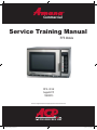
Service Training Manual
RFS Models
RFS - 60 Hz
August 2011
16400013
Amana® is a Registered Trademark of Maytag Corporation. Brand used under license.
1
2011 RFS Training Manual.indd 1
10/3/2011 8:36:35 AM
Table of Contents
Important Safety Information........................................................................................1-5
Quick Start Reference Guide......................................................................................9-11
!"#
$%&%'($%)*%
'($%)*%+
'%*!,(#+
,/0%((%2
2011 RFS Training Manual.indd 2
10/3/2011 8:36:35 AM
1
Important Safety Information
1
2011 RFS Training Manual.indd 1
10/3/2011 8:36:35 AM
Important Information
Important Notices for Servicers and Consumers
ACP will not be responsible for personal injury or property damage from improper service procedures. Pride and
workmanship go into every product to provide our customers with quality products. It is possible, however, that during
its lifetime a product may require service. Products should be serviced only by a qualified service technician who is
familiar with the safety procedures required in the repair and who is equipped with the proper tools, parts, testing
instruments and the appropriate service information. IT IS THE TECHNICIANS RESPONSIBLITY TO REVIEW ALL
APPROPRIATE SERVICE INFORMATION BEFORE BEGINNING REPAIRS.
!
WARNING
To avoid risk of severe personal injury or death, disconnect power before working/servicing on appliance to avoid
electrical shock.
To locate an authorized servicer please contact:
ComServ Support Center
Web Site
WWW.ACPSOLUTIONS.COM
.......................
Telephone Number
1-866-426-2621 or 319-368-8195
E-Mail: commercialservice@acpsolutions.com
Recognize Safety Symbols, Words, and Labels
!
DANGER
DANGER— Immediate hazards which WILL result in severe personal injury or death.
!
WARNING
WARNING— Hazards or unsafe practices which COULD result in severe personal injury or death.
!
CAUTION
CAUTION— Hazards or unsafe practices which COULD result in minor personal injury, product or property
damage.
2
2011 RFS Training Manual.indd 2
10/3/2011 8:36:36 AM
Important Safety Information
!
WARNING
Read the following information to avoid possible exposure to microwave radiation:
The basic design of the Microwave Oven makes it an inherently safe device to both use and service.
However, there are some precautions which should be followed when servicing the microwave to maintain this
safety. These are as follows:
1. Always operate the unit from an adequately
grounded outlet. Do not operate on a two-wire
extension cord.
8. Do not for any reason defeat the interlock
switches there is not valid reason for this action
at any time; nor will it be condoned by ACP.
2. Before servicing the unit (if unit is operable) perform
the microwave leakage test.
9. IMPORTANT: Before returning a unit to a
customer, be sure to check for proper switch
interlock action.
3. The oven should never be operated if the door does
not fit properly against the seal, the hinges or hinge
bearings are damaged or broken; the choke is
damaged, (pieces missing, etc.); or any other
visible damage can be noted. Check the choke
area to ensure that this area is clean and free of all
foreign matter.
10. The Microwave Oven should never be
operated with any components removed and/or
bypassed or when any of the safety interlocks are
found to be defective, or when any of the seal
surfaces are defective, missing, or damaged.
11. All microwave ovens meet all requirements
of the radiation control for Health and Safety Act of
1968. Due to measurement uncertainties, the
maximum leakage for the field will be 4mw/cm2.
4. If the oven operates with the door open and
produces microwave energy, take the following
steps:
A. Tell the user not to operate the oven.
B. Contact ACP ComServ immediately.
12. To ensure that the unit does not emit excessive
microwave leakage and to meet the Department
of Health and Human Services guidelines, check
the oven for microwave leakage using a microwave
oven leakage meter that complies with US
Government CDRH / FDA / DHHS requirements
and or any other local government requirements.
The maximum leakage level allowed by ACP
2
is 4mw/cm .
5. Always have the oven disconnected when the outer
case is removed except when making the "live"
tests called for in the Service Manual. Do not
reach into the equipment area while the unit is
energized. Make all connections for the test and
check them for tightness before plugging the cord
into the outlet.
6. Always ground the capacitors on the magnetron
filter box with an insulated-handle screwdriver
before working in the high voltage area of the
equipment compartment. Some types of failures
will leave a charge in these capacitors and the
discharge could cause a reflex action which could
make you injure yourself.
13. If servicer encounters an emission reading over
4mw/cm 2, the servicer is to cease repair and
contact the ACP ComServ Department
immediately for further direction. ACP
will contact the proper Government
Agency upon verification of the test results.
7. Always remember that in the area of the
transformer there is HIGH VOLTAGE. When the
unit is operating keep this area clear and free of
anything which could possibly cause an arc or
ground, etc.
3
2011 RFS Training Manual.indd 3
10/3/2011 8:36:36 AM
IMPORTANT SAFETY INSTRUCTIONS
Recognize this symbol as a SAFETY message
!
WARNING
0,*(%=*
U!&"
%*,*)!&4)%)*,%7&!*%U
%,7U%U%8*%"
%*)(,&4(
>?%*!&%*(=*
+ D@D',!!"!3
>??@DEED0,
F$>?H'D@'D?JD$DKE>
>L$DH>'D>L>J>MD0?J>
>@>NOP,
(
K!"&)8%,!
4,,))
%%)%,7!&%*
U
%)%3)!*%
',=*
MH'K>NDH@>
"
%
%"NDH@>*F
NDH@@N/>?'@N@'H'D@P
(2
# %,=*
D@EO
%)4,,%*
,*
2 %)**,4,(())
%T&%6
U)(8%T%
!6
))DHE@D'!>?'>
,3
H,=*
D@EO&%))*
)%!),**%%3
,%3
%,=*
',"
&3
")(),U7U
%)%"&))()&%)*%%
!%%"*
?4,"=*
UED>H$>JD@
%"4,*)!"E>@
D@D'
%,=*
&,
)()%)%
*(U&4%7(
%
%"U
%&,!)()%)%
)
',=*
U*)(
4%%)U*!
%3)D@EO!"=*)%3
%
%%=*%)%3=*
%*,%)%3&"&%
6U%
%U%)8*
D@D'3%%!7*3%%,%
(
=*
# D@D'%,=*
*)%D@D'
*,
%)*%4%V&%6
U%
7,7U4!U4(
U
%%
2 D@D'%%)%
*(4%
W
%)?0?O&%>?'>*%&
D@D'%),(3%)(&!%
counter.
%%*"
)%(%*
(?#&
,4%*
PRECAUTIONS TO AVOID POSSIBLE
EXPOSURE TO EXCESSIVE MICROWAVE
ENERGY
A. DO NOT
%,34,,)%
)%
%%*,%&*
6
*%%43%("
%)&%
%4,,&"%7
B. DO NOT
"!8!4,3&%&),)%4%%%)*
**(*%&
C. DO NOT
%,3&)()
%*%"
%,,3)%
%
%")
,,%)(,:
)%;!<
,(),;!%7%)<
)%)(*%&
',3,*)!)8*)%%
%)!""6
%
%"=*)%3
%
SAVE THESE INSTRUCTIONS
4
2011 RFS Training Manual.indd 4
10/3/2011 8:36:37 AM
IMPORTANT SAFETY INSTRUCTIONS
WARNING
WARNING
'3)%7&%,33":
E=*)*,4%U&&U%%!
!3%,)!"),!(
4,*
%(!!()**%&&,
=*)J!!*!!(%!(4,,%
%3)&%,%4334"
%'DHE>HE'@J>OD'
EXHH>@EOKDE@NDJ>0>@?
$DD@DD'>H'>@E@>'>@'D
'>EXH'%)*,%7&8*%"
%:
D@D'3%7&)%&*")3
4,
%U
U%,%!*!
%%
)),3&
7(
! 34%4&%
%%
!(!&%
(!(3
c.
I&%),3(U7
3
)%ED>U*%3&&))
,
4%%)U%,*&&
4%,&*%
%*!%7%
< 3%,,=*)
< %,=*)!,!&%),&4",%*(,
,(
< *%(,))%4,%%4
7
3< ?&%,(U4,%),
%433&%,%!&%%3(
,%
3< H6%%4,%(
%
,%*,%
) D@D'*,3"&%%(D@D'
3
%
%)*U7(*U%&)
,3"4,*
!
CAUTION
'3)
%8*%"%
%
%")(U!%3,&4(:
)
&&%"3*)3%,
)!,%)*,)
+ @3%*
%U
U%,%!*!
%,%))&%7(
7%%,((,%4,
*!%7"7*(%43%("
$%*%"!*)*
)%*
$%"7
4,&%7%7&!&%7(
0,7(4,
%U
U%,%
!*!%U&4*&*%%Y
%)
%)**
*
%44,,"%
,%",!%)",*)
)*
%(
$%7&
UU)%
&)!&%7(4,%43%("
0,7
%)U
3"
,)%%
!(
3)%=*)*)6
)=*7")
*%%!(!%7$%%
%%!(!&%,(
# %=*
4,*)%&)
33"
5. M%43
%,*)!
)
3
'3)
7%&*U*
,"%
7%*&*%%!*
&&&%43%("
7%
*%(*%7(,%%
3M7(,%%
%*%")"*%%U
&*U%)(3
# ?*,%)%3%MH'
=*
*"%)
)%
%&%
&**%*
**3
***&3
SAVE THESE INSTRUCTIONS
5
2011 RFS Training Manual.indd 5
10/3/2011 8:36:38 AM
2
RFS 60 Hz Specifications
Installation
· Unpacking the oven
· Radio Interference
· Oven Placement
Power Specification
· Input- Power Source
· Output- Power Source
· Power Consumption
Cavity Dimensions
· Weight
6
2011 RFS Training Manual.indd 6
10/3/2011 8:36:38 AM
Installation
Unpacking Oven
Oven Placement
Z 3&%)(*,))%%
))33"
Z %")%!%7(*%&
*%,
)"
*3&)()
Z 3%&%3%%
Z &3,!%)6%")%U4
&4,*%!&%(
4%
Z 36%!3*%&,U
*,
3%)
&&%"%',*)*
%433
%
%
%")*)
,%&&%
%
Z !7%!%*3%?4&%
(
Z 33*%
*%&
Radio Interference
M%43
%"*%&%%)U
3U%%3)*%
%&%!")(,&4(:
Z )%)(*%&&3%)(
%*F%)(P
Z $%)U3U&%
!
&%3
Z H
%
%")%)U3U
!%(%(%
A
A
A
B
A—?4[,/%&
%%*)
))&=*
$%
%%\4%*)=*
%
0,%%)%\4U3"
%
%
%")&&%
%
reduced.
Oven Clearances
7
2011 RFS Training Manual.indd 7
10/3/2011 8:36:38 AM
Models
Power Source
J(?
?
%(
%=*"
($,U4%(%*))
$*((*%/%)
Power Output
@%43%("
;>2<
M*
%*%%
D
%(%=*"
Power Consumption
7)M%43
Dimensions
Cabinet
0),
(,
,
Cavity Dimensions
0),
(,
,
Weight
Crated
Uncrated
RFS12MPSB, RFS12SW2B,
RFS12SW2C, RFS12TS(W)
RFS18MPS, RFS18TS
J
?
60 Hz
X
@>M?2
#J
?
60 Hz
X
@>M?
0
0
b/2b
#2M
b/b
#2M
0U
0
gP;22<
#hP;<
hP;2#<
gP;22<
#hP;<
hP;2#<
#hP;<
+P;<
/P;#<
#hP;<
+P;<
/P;#<
!;7(<
#!;+7(<
!;7(<
!;7(<
8
2011 RFS Training Manual.indd 8
10/3/2011 8:36:38 AM
3
RFS 60 Hz Quick Start
Reference Guide
Control Panel
· Manual operation
· Programming items
· Qty 2X Pad
Clean Filter
User Options
· Changing options
· Factory presets
9
2011 RFS Training Manual.indd 9
10/3/2011 8:36:39 AM
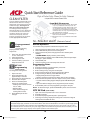
Quick Start Reference Guide
Refer to Product Safety Manual for Safety Statements
CLEAN FILTER
CLEAN FILTER
Complete Owner’s Manual available online
This oven displays
at user
))%30,,(
displays ACP recommends cleaning the
%%,%*(,y. Cleaning the air
The message will stop displaying
automatically after 24 hours. Depending
on microwave use and environmental
)U,%")!
cleaned more frequently. Once the
frequency is determined, set the option
for the appropriate time frame.
Oven Wall Clearances
A—For North American (UL/CSA) models, allow at least
2” (5.1 cm) of clearance around top of oven. For
International (50 Hz) models, allow at least 12” (30
cm) of clearance around top of oven. Proper air
\4%*)3%
0,
%%)%\w, oven may not operate properly and
life of electrical parts is reduced.
B—Allow at least 2” (5.1 cm) between air discharge on
back of oven and back wall.
C—Allow at least 2” (5.1 cm) of clearance around sides
of oven.
So...how do I use it?
Preprogrammed
Pads
To cook food using
preprogrammed cooking
=*:
1. Open oven door and place food
in oven. Close door.
2. Press desired pad.
3. Oven begins to cook.
4. At end of cooking cycle oven
beeps and shuts off.
QTY 2X
Programming
(some models)
T,(,7(&%:
1. Open oven door.
2. Press and hold pad 1 for
approximately 5 seconds.
3. Press pad to be reprogrammed.
4. Press the QTY 2X pad.
5. Press a numbered pad to
change the cooking factor.
Z Cooking factor can be set from
10% to 100%.
Z Default is 80%.
Z Pad 5 would change the
cooking factor to 50%.
6. Press START pad to save
changes.
(Electronic Control)
Manual Operation
T7&)*(
%))
4%3:
1. Open oven door and place food in oven. Close door.
2. Press TIME ENTRY pad and enter cooking time.
3. Press a power level pad to change power level if desired (some
models).
Z COOK LEVEL displays with the power setting.
4. If stage cooking is desired, press TIME ENTRY pad and repeat steps
2 through 4, (some models).
5. Press START pad.
6. At end of cooking cycle oven beeps and shuts off.
Programming Items
1.
2.
3.
4.
5.
6.
Open oven door.
Press and hold pad 1 for approximately 5 seconds.
Press pad to be reprogrammed.
Enter cooking time by using the number pads.
Press a power level pad to change power level if desired.
If stage cooking is desired, press TIME ENTRY pad.
Z "!%\",4,(*!r.
Z Display changes to cook time and power level for the next stage.
7. Enter cook time and power level as in steps 4 and 5 (some models).
Z To enter another cooking stage for that pad, press TIME ENTRY pad
again.
Z Up to four different stages can be programmed (some models).
8. Press START pad to set new programming changes to the pad.
NOTE: To discard changes, press STOP/RESET pad or close oven door.
QTY 2X Pad
1.
2.
3.
4.
(some models)
Open oven door and place food in oven. Close door.
Press QTY 2X pad.
Press desired preprogrammed pad or pad sequence.
Oven begins cooking. Displayed cooking time is the total of original
cooking time and added 2X time.
The switching operation of this microwave oven can cause voltage \*tuations on the supply line. The operation of this oven under
unfavorable voltage supply conditions can have adverse effects. This device is intended for the connection to a power supply system
with a maximum permissible system impedance Zmax of at the interface point of the user’s supply. The user has to
*%,,)3)"
4%*
""4,,&*,%=*%!3&%", the user
can ask the public power supply company for the system impedance at the interface point.
10
2011 RFS Training Manual.indd 10
10/3/2011 8:36:39 AM
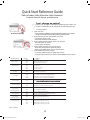
Quick Start Reference Guide
Refer to Product Safety Manual for Safety Statements
Complete Owner’s Manual available online
Can I change an option?
Options such as single or double pad programming, beep volume, and
maximum cooking time can be changed to suit individual preferences.
To change options:
1. Open oven door.
Z If door is closed or RESET pad is pressed before programming is complete,
changes are discarded and microwave exits programming mode.
2. Press and hold pad 2 for approximately 5 seconds.
Z This begins options mode.
Z Microwave will beep and 0P: displays.
3. Press number pad that controls option to be changed.
Z See table below for options.
Z Current option will display.
4. Press number pad again to change the option.
Z Each time pad is pressed, option will change.
Z Match code displayed with code for desired option.
5. Press START pad to save changes.
Z To change additional options, repeat steps 3 and 4.
Z Changes appear after door is closed or STOP/RESET pad is pressed.
DO NOT power spray
No metal pans
Numbered Pads
1
End of Cycle Beep
Display
Options
OP:10
3 second beep.
OP:11
Continuous beep until door is opened.
OP:12
5 beep bursts until door is opened.
2
OP:20
Eliminates beep.
Key Beep Volume
OP:21
Sets volume to low.
OP:22
Sets volume to medium.
3
Key Beep
4
Active Display
OP:23
Sets volume to high.
OP:30
Prevents beep when pad is pressed.
OP:31
Allows beep when pad is pressed.
OP:40
15 seconds after oven door is opened, keyboard disabled.
OP:41
30 seconds after oven door is opened, keyboard disabled.
OP:42
1 minute after oven door is opened, keyboard disabled.
OP:43
2 minutes after oven door is opened, keyboard disabled.
5
OP:50
Prevents
On-the Fly Cooking
OP:51
Allows
6
OP:60
Opening oven door does not reset oven back to ready mode.
Reset to Ready Mode
7
(some models)
.
.
OP:61
Opening oven door resets oven back to ready mode.
OP:70
Allows 60 minutes of heating time (some models).
OP:71
Allows 10 minutes of heating time.
OP:80
Allows use of preprogrammed pads only.
Maximum Heating Time
8
Manual Operation
9
(some models)
OP:81
Allows use of manual time entry and preprogrammed pads.
OP:90
Allows 10 (0-9) preprogrammed pads.
OP:91
Allows 100 (00-99) preprogrammed pads.
Double Digit Operation
0
Clean Filter Message
OP:00
Do not display message.
OP:01
Display message for 24 hours every 7 days.
OP:02
Display message for 24 hours every 30 days.
OP:03
Display message for 24 hours every 90 days.
Part No.12804405
11
2011 RFS Training Manual.indd 11
10/3/2011 8:36:40 AM
4
RFS 60 Hz Components Location
12
2011 RFS Training Manual.indd 12
10/3/2011 8:36:40 AM
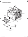
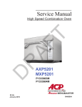
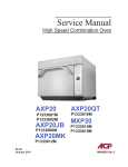
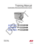
Components Location
Cavity
TCO
Top
Stirrer Motor
Blower Motor
H.V.
Capacitor
H.V.
Capacitor
Top
Antenna
Diode
Diode
Transformer
Magnetron
TCO’s
Fuse Magnetrons
Board
Oven Door
Interlock
Switch
Control Panel
Splatter Shield
Transformer
Bottom
Antenna
Oven Tray
Bottom
Stirrer Motor
Suction Cup
(Used for aid in removing oven tray)
59001235
13
2011 RFS Training Manual.indd 13
10/3/2011 8:36:41 AM
5
Disassembly
Door removal
· Disassembly
Control panel removal
· Wire terminals
14
2011 RFS Training Manual.indd 14
10/3/2011 8:36:41 AM
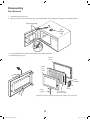
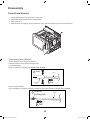
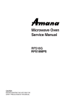
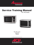
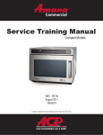
Disassembly
Door Removal
1. Disconnect power to oven.
2. Open oven door, remove top hinge cap, and slowly lift door to disengage the hinge pins at top and bottom.
Top hinge cap
Top
hinge
cap
3. To reinstall door, place top pin into slot first, then align bottom pin.
4. Reinstall top hinge cap.
Choke
cover
Outer
Door
panel
Latch
assembly
* Door
Handle
Spring
Door frame/
choke assembly
* Apply thread lock compound to threads, tighten side screw first.
15
2011 RFS Training Manual.indd 15
10/3/2011 8:36:42 AM
Disassembly
Control Panel Removal
1.
2.
3.
4.
Disconnect power to oven and remove outer case.
Disconnect and label wires from controller/timer.
Open oven door.
Remove screw securing top of control panel to cavity. Lift control panel up and out to release tabs.
Disconnecting Wire Terminals
All wire terminals are locking-type terminals.
Proceed as follows to disconnect wire terminals:
Insulated terminals:
Grasp insulator pod and pull back. DO NOT PULL ON WIRE.
1 Grasp
Wire
2 Pull
Insulator
Pod
Non-insulated terminals:
Use a small blade screwdriver to depress locking-tab and pull on terminal. DO NOT PULL ON WIRE.
1 Release
locking-tab
Wire
2 Pull
16
2011 RFS Training Manual.indd 16
10/3/2011 8:36:43 AM
6
Performance Testing
Procedures
17
2011 RFS Training Manual.indd 17
10/3/2011 8:36:43 AM
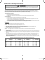
Performance Testing Procedures
!
WARNING
To avoid risk of electrical shock, personal injury or death, disconnect power to oven and discharge capacitor
before servicing, unless testing requires it.
All Amana and Menumaster microwave oven power outputs are rated using the IEC705 standards. Using the
IEC705 test method requires precision measurements and equipment that is not practical to be performed in the
field. Using the test shown below will indicate if the oven performance is satisfactory.
Test equipment required:
x
x
1000 ml test container and thermometer.
Digital watch / watch with a second hand for use on ovens with electromechanical timers.
Important Notes:
x
x
x
Low line voltage will cause low temperature rise / power output.
Ovens must be on a dedicated circuit, properly grounded, and polarized. Other equipment on the same
circuit may cause a low temperature rise / power output.
This test and results are not a true IEC705 test procedures and are only intended to provide servicers with
an easy means of determining if the microwave oven cooking output is correct.
Procedure
1. Fill the test container to the 1000 ml line with cool tap water.
NOTE:
Water temperature should be approximately 60qF / 16qC
2. Using the thermometer, stir water for five to ten seconds; measure, and record the temperature (T1).
3. Place test container of water in the center of oven cavity and close door.
4. Heat the water for a 33-second full power cycle.
NOTE:
Use a digital watch or a watch with a second hand for ovens with electromechanical timers.
5. At end of the cycle, remove test container. Using the thermometer, stir water for five to ten seconds and record
temperature (T2).
6. Subtract the starting water temperature (T1), from the ending water temperature (T2) to obtain the temperature
rise (T).
7. If the temperature rise (T) meets or exceeds the minimum, the test is complete. If the temperature rise (T)
fails to meet the minimum temperature rise, test the line voltage to verify it is correct. Then repeat steps 1 - 6
making sure to change the water. If the temperature rise (T) fails to meet the minimum temperature rise again
the oven will require service.
Minimum Temperature Rise at Thirty -Three (33) Seconds Run Time
T
(°F)
Cooking
Power Output
10 ................. 1000
11 ................. 1100
12 ................. 1200
14 ................. 1400
17 ................. 1700
18 ................. 1800
19 ................. 1900
T
(°F)
Cooking
Power Output
T
(°C)
20 ................. 2000
21 ................. 2100
22 ................. 2200
24 ................. 2400
25 ................. 2500
27 ................. 2700
30 ................. 3000
Cooking
Power Output
5 .............. 1000
5.5 ............ 1100
6.5 ............ 1200
7.5 ............ 1400
9.5 ............ 1700
10 ............. 1800
10.5 .......... 1900
T
(°C)
Cooking
Power Output
11............ 2000
11.5......... 2100
12............ 2200
13............ 2400
13.5......... 2500
15............ 2700
16.5......... 3000
18
2011 RFS Training Manual.indd 18
10/3/2011 8:36:44 AM
7
Component Testing Procedures
19
2011 RFS Training Manual.indd 19
10/3/2011 8:36:44 AM
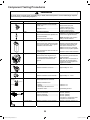
Component Testing Procedures
!
WARNING
To avoid risk of electrical shock, personal injury or death, disconnect power to oven and discharge capacitor
before servicing, unless testing requires it.
Illustration
Component
Thermal cutout
Testing
Disconnect all wires from TCO.
Measure resistance across terminals.
Cavity TCO .............................................
Magnetron TCO ......................................
Diode
Discharge Capacitor
Remove diode lead from capacitor and
connect ohmmeter.
Capacitor
Reverse leads for second test.
Discharge Capacitor
Remove wires from capacitor terminals
and connect ohmmeter, set on highest
resistance scale to terminals.
Magnetron
Also check between each terminal and
capacitor case.
Discharge Capacitor
Remove wires from magnetron and
connect ohmmeter to terminals. Also
check between each terminal and
ground.
Blower motor
Transformer
NOTE: Ohmmeter must contain a
battery of 6 volts minimum.
Between Terminals: Meter should
momentarily deflect towards zero
then return to over 5 M:. If no
deflection occurs, or if continuous
deflection occurs, replace capacitor.
Terminal to Case: Infinite resistance
Between Terminals: Less than 1 :
Each terminal to ground measures
Infinite resistance.
Note: This test is not conclusive. If
oven does not heat and all other
components test good replace the
magnetron and retest.
Approximately 28 – 35 :
Remove all wires from motor.
Measure resistance across terminals .....
Secondary
Closed at 32qF (0qC) and
Opens at 230qF (110qC)
Closed at 140qF (60qC) and
Opens at 320qF (160qC)
Infinite resistance should be
measured in one direction and 50K:
or more in the opposite direction.
Remove all wires from motor.
Measure resistance across coil ..............
Stirrer motor
Results
Approximately 12 – 14 K:
Discharge Capacitor
Remove all wires from terminals.
Filament
Measure resistance from:
Primary .................................................. Less than <1 :
Filament................................................. Less than <1 :
Secondary to Ground screw on
transformer stack................................... Approximately 90-100 :
Primary
Noise filter board
Power In terminals ..................................
Power Out terminals ...............................
Power In terminals ..................................
Power Out terminals ...............................
120 VAC (RFS12)
120 VAC (RFS12)
240 VAC (RFS18)
240 VAC (RFS18)
If no power in, check power outlet.
If no power out, check fuses.
Circuit Protector
Measure resistance across terminals .....
Between Terminals: Less than 1 :
20
2011 RFS Training Manual.indd 20
10/3/2011 8:36:45 AM
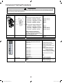
Component Testing Procedures
!
WARNING
To avoid risk of electrical shock, personal injury or death, disconnect power to oven and discharge capacitor
before servicing, unless testing requires it.
Illustration
Component
Interlock switch assembly
Testing
Disconnect wires to switch.
Results
With door open measure resistance from:
Top Monitor – COM (PK) – NO (BL) ........
Btm Monitor – COM (WH) – NO (RD) ......
Top Primary – COM (RD BK) – NC (BN)
Btm Primary – COM (BK) – NC (BL)........
Secondary – COM (PK) – NC (GN) ........
Indicates continuity
Indicates continuity
Infinite :
Infinite :
Infinite :
With door closed measure resistance from:
Top Monitor – COM (PK) – NO (BL).......
Btm Monitor – COM (WH) – NO (RD) ......
Top Primary – COM (RD BK) – NC (BN)
Btm Primary – COM (BK) – NC (BL)........
Secondary – COM (PK) – NC (GN) ........
Infinite :
Infinite :
Indicates continuity
Indicates continuity
Indicates continuity
After verifying or replacing the
module, reconnect wires to switch
and check operation of monitor circuit
before operating the oven.
Lamp receptacle
Test continuity of receptacle terminals.
Wire Harness
Test continuity of wires
Service Test Mode:
Error codes:
Indicates continuity with bulb
installed.
Indicates continuity
Electronic Control Panel
SERVICE appears in the display
Open door, Press and Hold pad 3 for 5
seconds to enter service test mode.
Press Pad 1.................................................. Indicates number of hours
magnetron has been turned on
Press Pad 2.................................................. Indicates number of times
magnetron tube has been turned
on and off
Press Pad 3.................................................. Indicates number of door cycles
Press Pad 4.................................................. CLEAR (Press START pad to
reset service data.)
Press Pad 5.................................................. Indicates amperage (Top Mag)
Press Pad 6.................................................. Indicates amperage (Bottom Mag)
Press Pad 7..................................................
Press Pad 8..................................................
Press Pad 9..................................................
Press Pad 0..................................................
Stop/Reset Pad ............................................
E-08..............................................................
E-09..............................................................
E-10..............................................................
RESET (Clear Service Alarm)
N/A
N/A
N/A
Exit Service Test Mode
Replace Control Board
Replace Control Board
Shorted or Open Keypad – Test
and replace if necessary
21
2011 RFS Training Manual.indd 21
10/3/2011 8:36:46 AM
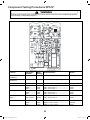
Component Testing Procedures RFS12*
!
WARNING
To avoid risk of electrical shock, personal injury or death, disconnect power to oven and discharge capacitor
before servicing, unless testing requires it.
RLY 3
1
2
TAB 1
TAB 2
9 8
5 4 3
1
CN1
Function
Power to current
transformer
Power from current
transformer
Power from Oven TCO
Power to Oven Light
Power to Blower Motor
Secondary Interlock
Switch
Power to Relay 3
Test Set-Up /
Condition
All Conditions
Meter
Setting
Volts
Probe Placement
Results
Tab 1 to CN1 Pin 3 (Neutral)
120 VAC
All Conditions
Volts
Tab 2 to CN1 Pin 3 (Neutral)
120 VAC
All Conditions
Standby .............
Ready................
Cook..................
Standby .............
Ready................
Cook..................
Door Closed ......
Door Opened ....
Volts
Volts
Volts
Volts
Volts
Volts
Volts
Ohms
Ohms
CN1 – Pin 1 (Black wire to Neutral)
CN1 – Pin 4 to Pin 1 .............................
CN1 – Pin 4 to Pin 1 .............................
CN1 – Pin 4 to Pin 1 .............................
CN1 – Pin 5 to Pin 1 .............................
CN1 – Pin 5 to Pin 1 .............................
CN1 – Pin 5 to Pin 1 .............................
CN1 – Pin 8 to Pin 9 .............................
CN1 – Pin 8 to Pin 9 .............................
120 VAC
120 VAC
0 VAC
0 VAC
120 VAC
0 VAC
0 VAC
Continuity
Infinite
Standby .............
Ready................
Cook..................
Volts
Volts
Volts
Relay 3 – Pin 1 to Pin 2 ........................
Relay 3 – Pin 1 to Pin 2 ........................
Relay 3 – Pin 1 to Pin 2 ........................
120 VAC
120 VAC
0 VAC
22
2011 RFS Training Manual.indd 22
10/3/2011 8:36:46 AM
Component Testing Procedures RFS18*
!
WARNING
To avoid risk of electrical shock, personal injury or death, disconnect power to oven and discharge capacitor
before servicing, unless testing requires it.
RLY 3
1
2
TAB 1
TAB 2
9 8
5 4 3
1
CN1
Function
Power to current
transformer
Power from current
transformer
Power from Oven TCO
Power to Oven Light
Power to Blower Motor
Secondary Interlock
Switch
Power to Relay 3
Test Set-Up /
Condition
All Conditions
Meter
Setting
Volts
Probe Placement
Results
Tab 1 to CN1 Pin 3
208 / 240 VAC
All Conditions
Volts
Tab 2 to CN1 Pin 3
208 / 240 VAC
All Conditions
Standby .............
Ready................
Cook..................
Standby .............
Ready................
Cook..................
Door Closed ......
Door Opened ....
Volts
Volts
Volts
Volts
Volts
Volts
Volts
Ohms
Ohms
CN1 – Pin 1 (Black wire to ground)
CN1 – Pin 4 to Pin 1 .............................
CN1 – Pin 4 to Pin 1 .............................
CN1 – Pin 4 to Pin 1 .............................
CN1 – Pin 5 to Pin 1 .............................
CN1 – Pin 5 to Pin 1 .............................
CN1 – Pin 5 to Pin 1 .............................
CN1 – Pin 8 to Pin 9 .............................
CN1 – Pin 8 to Pin 9 .............................
208 / 240 VAC
208 / 240 VAC
0 VAC
0 VAC
208 / 240 VAC
0 VAC
0 VAC
Continuity
Infinite
Standby .............
Ready................
Cook..................
Volts
Volts
Volts
Relay 3 – Pin 1 to Pin 2 ........................
Relay 3 – Pin 1 to Pin 2 ........................
Relay 3 – Pin 1 to Pin 2 ........................
208 / 240 VAC
208 / 240 VAC
0 VAC
23
2011 RFS Training Manual.indd 23
10/3/2011 8:36:47 AM
8
Troubleshooting
24
2011 RFS Training Manual.indd 24
10/3/2011 8:36:47 AM
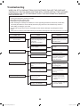
Troubleshooting
WHEN YOU GET A COMPLAINT FROM YOUR CUSTOMER, EVALUATE THE COMPLAINT
CAREFULLY. IF THE FOLLOWING SYMPTOMS APPLY, PLEASE INSTRUCT THE CUSTOMER
IN THE PROPER USE OF THE MICROWAVE OVEN. THIS CAN ELIMINATE AN UNNECESSARY SERVICE CALL.
1. Check grounding before checking for trouble.
2. Be careful of the high voltage circuit.
3. Discharge the high voltage capacitor.
4. When checking the continuity of the switches or of the high voltage transformer, disconnect one lead wire
from these parts and then check continuity with the AC plug removed. To do otherwise may result in a
false reading or damage to your meter.
5. Do not touch any part of the circuit on the PCB since static electric discharge may damage this control
panel.
Always touch yourself to ground while working on this panel to discharge any static charge built up in your body.
CONDITION
Microwave oven
does not work.
Output power is too low.
Sparks occur.
Uneven cooking.
CAUSE
REMEDY
Inserting many plugs into one
outlet and using them at the
same time
(blown fuse or breaker)
Avoid using other electrical
appliances when you use the
microwave oven.
Microwave oven plug is not
inserted tightly.
Insert microwave oven plug
securely.
Low AC input voltage.
Use the microwave oven at
adequate line voltage.
Food temperature is too low.
This may not be a defect.
It is possible that the food
should be cooked for a
longer time period.
Using metallic ware and
allowing it to touch the oven
wall.
Do not use metallic ware for
cooking except that noted in
the cooking guide.
Ceramic ware trimmed in
gold or silver powder is used.
Do not use any type of
cookware with metallic
trimming.
Inconsistent intensity of
microwave by their
characteristics.
1. Use plastic wrap or lid.
2. Stir once or twice while
cooking soup, cocoa or
milk, etc.
Display “CALL SERVICE”
See Service Test Mode page 21
to clear CALL SERVICE .
25
2011 RFS Training Manual.indd 25
10/3/2011 8:36:47 AM
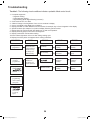
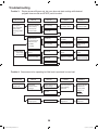
Troubleshooting
Trouble 1: The following visual conditions indicate a probable failed control circuit.
1. Incomplete segments.
Z Segment missing.
Z Partial segment missing.
Z Digit \7%( (Note: Slight \7%( is normal.)
2. )*%%!7
3. A distinct change in the brightness of one or more numbers in display.
4. One or more digits in the display are not lighting.
5. Display indicates a number dif&%&%*,)U&%6
U7"2)
%,)
y.
6. numbers (for example 7 or 9) will not display when 7" pad is touched.
7. ")*)44,!7(%*
4,7
%
8. Display obviously jumps in time while counting down.
9. "*)4&4,7(
10. >,)%(,)*%&%(7("
11. Display time of day does not reappear when 7( is ,)
CONDITION
CHECK
1. No input can be
programmed.
Check the connection between
membrane key
assembly and
PCB assembly.
Continuity.
Defective PCB
assembly.
Replace PCB
assembly.
No continuity.
Loose
connection.
Connect them
tightly.
Replace key
membrane
assembly and
check operation.
Everything works
Defective key
membrane
assembly.
Replace key
membrane
assembly.
Defective PCB
assembly.
Replace PCB
assembly.
2. Some inputs
cannot be
programmed.
3. Display shows a
e
num
e
touched.
RESULT
Still have trouble.
CAUSE
REMEDY
4. Random
programming
when touching
other pads.
and can not
accept any
input.
26
2011 RFS Training Manual.indd 26
10/3/2011 8:36:48 AM
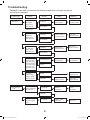
Troubleshooting
Trouble 2: Oven does not operate at all, Display window does not display any (*%U
)
*
)
CONDITION
1. Fuse blows.
CHECK
Check continuity
of monitor
switch (with
door closed).
RESULT
Continuity.
CAUSE
REMEDY
Malfunction of the
monitor switch.
Replace fuse,
interlock assembly
Shorted contact at
the primary switch.
Replace fuse,
interlock assembly
No continuity.
Replace fuse
Check continuity
of primary
switch (with
door opened).
Continuity.
Check continuity
of secondary
switch (with
door opened).
Continuity.
Disconnect one
side of the wire
lead connected
from transformer
to the high voltage
capacitor and
operate the unit.
2. Fuse does not
blow.
No continuity.
Malfunction of
secondary switch.
Replace fuse,
interlock assembly
No continuity.
Fuse blows again
Defective high voltage transformer.
Replace high voltage transformer.
Normal.
Set is good condition
(defective fuse only)
Measure to
resistance high
voltage capacitor
(refer to page 20)
Normal.
Abnormal.
Defective high
voltage capacitor.
Check continuity
of oven TCO.
No continuity.
Defective
oven TCO.
Replace
oven TCO.
Defective power
supply cord.
Replace power
supply cord.
Replace high
voltage capacitor.
Continuity.
Check continuity
of power supply
cord.
No continuity.
27
2011 RFS Training Manual.indd 27
10/3/2011 8:36:48 AM
Troubleshooting
Trouble 3:
Display shows all (*% U !* 3 ) % 7( 4, )%)
%(%%)TART
)*,)
CONDITION
1.Setting time
does not count
down when
touching START
pad.
2. Blower motor
or oven lamp
do not turn on.
CHECK
RESULT
CAUSE
REMEDY
Defective
secondary switch.
Replace
secondary switch.
Check continuity
of secondary
switch (with
door closed).
No continuity.
Check the connection between
CN1 connector
and PCB
assembly.
Continuity
Defective PCB
assembly.
Replace PCB
assembly.
No continuity
Loose connection.
Connect them
tightly.
Check blower
motor.
Abnormal.
Defective blower
motor.
Replace blower
motor.
Check oven lamp.
Abnormal.
Defective oven lamp.
Replace oven lamp.
Continuity.
Normal.
Trouble 4:D3!
%(!*,
%)*)3)
CONDITION
Output is low.
CHECK
Check the
power source
voltage.
RESULT
Lower than 90% of
rating voltage.
CAUSE
Decrease in power
source voltage
with load.
Normal.
REMEDY
Suggest customer
contact local
electric power
utility co. or
electrician.
Measure the
output power.
Abnormal.
Defective
magnetron.
Replace
magnetron.
28
2011 RFS Training Manual.indd 28
10/3/2011 8:36:48 AM
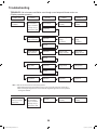
Troubleshooting
TROUBLE 5: No microwave oscillation even though oven lamp and blower motor run.
(Display operates properly)
CONDITION
No microwave
oscillation.
CHECK
Disconnect the
wire leads from
relay 3 and check
continuity of relay 3
(Operate the unit)
Check high voltage transformer
RESULT
No continuity.
CAUSE
REMEDY
Defective PCB
assembly
Replace PCB
assembly
Defective high
voltage
transformer.
Replace high
voltage
transformer.
Defective high
voltage capacitor.
Replace high
voltage capacitor.
Defective high
voltage diode.
Replace high
voltage diode.
Defective
magnetron.
Replace
magnetron.
Continuity.
Abnormal
Normal
Check high voltage capacitor
Abnormal
Normal
Check high voltage diode
Abnormal
Normal
Check
magnetron.
Abnormal
/05&t.BLFTVSFUIFXJSFMFBETBSFJOUIFDPSSFDUQPTJUJPO
t8IFO3FNPWJOHUIFXJSFMFBETGSPNUIFQBSUTCFTVSFUPHSBTQUIFDPOOFDUPSOPUUIFXJSFT
t8IFOSFNPWJOHUIFNBHOFUSPOCFTVSFUPJOTUBMMUIFNBHOFUSPOHBTLFUJOUIFDPSSFDUQPTJUJPO
BOEJOHPPEDPOEJUJPO
Output is full power
when you set lower
power level.
Disconnect the
wire leads from
relay 3 and check
continuity of relay 3
(Operate the unit)
Abnormal.
Defective PCB
assembly.
Replace PCB
assembly.
29
2011 RFS Training Manual.indd 29
10/3/2011 8:36:49 AM
9
Schematic / Wiring Diagrams
30
2011 RFS Training Manual.indd 30
10/3/2011 8:36:49 AM
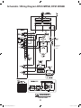
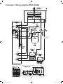
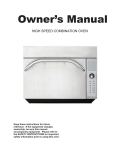
Schematic / Wiring Diagram RFS12MPSB, RFS12SW2B
BTM PRIMARY
INTERLOCK
SWITCH
! DANGER
HIGH VOLTAGE
31
2011 RFS Training Manual.indd 31
10/3/2011 8:36:49 AM
Schematic / Wiring Diagram RFS12SW2C
! DANGER
HIGH VOLTAGE
32
2011 RFS Training Manual.indd 32
10/3/2011 8:36:50 AM
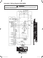
Schematic / Wiring Diagram RFS12TS(W)
TAB 1
TAB 2
BTM PRIMARY
INTERLOCK
SWITCH
33
2011 RFS Training Manual.indd 33
10/3/2011 8:36:50 AM
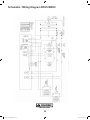
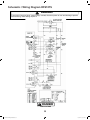
Schematic / Wiring Diagram RFS18MPS
!
WARNING
To avoid risk of electrical shock, personal injury or death, disconnect power to oven and discharge capacitor
before servicing, unless testing requires it.
! DANGER
34
2011 RFS Training Manual.indd 34
10/3/2011 8:36:51 AM
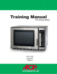
Schematic / Wiring Diagram RFS18TS
!
WARNING
To avoid risk of electrical shock, personal injury or death, disconnect power to oven and discharge capacitor
before servicing, unless testing requires it.
! DANGER
HIGH VOLTAGE
35
2011 RFS Training Manual.indd 35
10/3/2011 8:36:51 AM
$%@#
$%)H?/
2011 RFS Training Manual.indd 36
www.acpsolutions.com
¤ ?$
)%
)U42##
10/3/2011 8:36:51 AM