1
Configuring Serial Interfaces
Use the information in this chapter to configure serial interfaces.
For information on configuring an Asynchronous Transfer Mode (ATM) interface, see the
“Configuring ATM Access over a Serial Interface” chapter in the Wide-Area Networking
Configuration Guide.
See also the section “Configure the CRC” in the section “Configure a Synchronous Serial Interface”
in this chapter.
For hardware technical descriptions and information about installing interfaces, refer to the
hardware installation and configuration publication for your product. For a complete description of
serial interface commands used in this chapter, refer to the “Interface Commands” chapter of the
Cisco IOS Interface Command Reference. To locate documentation of other commands that appear
in this chapter, use the command reference master index or search online.
These sections are included in this chapter:
•
•
•
•
•
•
•
•
•
Configure a High-Speed Serial Interface
Configure a Synchronous Serial Interface
Configure a Channelized T3 Interface Processor
Configure PA-E3 and PA-2E3 Serial Port Adapters
Configure PA-T3 and PA-2T3 Serial Port Adapters
Configure a Packet OC-3 Interface
Configure Automatic Protection Switching of Packet-over-SONET Circuits
Configure Serial Interfaces for CSU/DSU Service Modules
Configure Low-Speed Serial Interfaces
For examples of configuration tasks shown in this chapter, see “Serial Interface Configuration
Examples” at the end of this chapter.
Configure a High-Speed Serial Interface
The High-Speed Serial Interface (HSSI) Hip Interface Processor (HIP) provides a single HSSI
network interface. The network interface resides on a modular interface processor that provides a
direct connection between the high-speed CiscoBus and an external network.
The HSSI port adapters (PA-H and PA-2H) are available on Cisco 7200 series routers, on
second-generation Versatile Interface Processors (VIP2s) in Cisco 7500 series routers, and on Cisco
7000 series routers with the 7000 Series Route Switch Processor (RSP7000) and 7000 Series Chassis
Configuring Serial Interfaces IC-67
Configure a High-Speed Serial Interface
Interface (RSP7000CI). The PA-H provides one high-speed synchronous serial interface, and the
PA-2H provides two high-speed synchronous serial interfaces that support full-duplex and data rates
up to 52 Mbps. For more information on the PA-H and PA-2H, refer to the PA-H and PA-2H HSSI
Port Adapter Installation and Configuration publication.
The Cisco 3600 series 1-port HSSI network module provides full-duplex connectivity at
Synchronous Optical Network (SONET) OC-1/STS-1 (51.840 Mhz), T3 (44.736 MHz), and E3
(34.368 MHz) rates in conformance with the EIA/TIA-612 and EIA/TIA-613 specifications. The
actual rate of the interface depends on the external data service unit (DSU) and the type of service
to which it is connected. This 1-port HSSI network module can reach speeds of up to 52 Mbps in
unidirectional traffic with 1,548-byte packets and 4,250 packets per second. Asynchronous Transfer
Mode (ATM), High-Level Data Link Control (HDLC), Point-to-Point Protocol (PPP), Frame Relay,
and Switched Multi-Megabit Data Service (SMDS) WAN services are all fully supported.
Before you configure the 1-port HSSI network module, complete the following prerequisite tasks:
•
Install the HSSI Network Module in a chassis slot. For information on how to install this network
module, refer to the “Installing a 1-Port HSSI Network Module in a Chassis Slot” section in the
1-Port HSSI Network Module Configuration Note.
•
Complete basic device configuration, including host name, username, protocol, and security
configuration. For more information about basic device configuration, refer to the Cisco 3620
Installation and Configuration Guide or the Cisco 3640 Installation and Configuration Guide.
HSSI Configuration Task List
Perform the tasks in the following sections to configure a HSSI interface. The first task is required;
the remaining tasks are optional.
•
•
•
•
•
Specify a HSSI
Specify HSSI Encapsulation
Invoke ATM on a HSSI Line
Convert HSSI to Clock Master
Disable Fair Queueing
Specify a HSSI
To specify a HSSI and enter interface configuration mode, use one of the following commands in
global configuration mode:
IC-68
Command
Purpose
interface hssi number
Begin interface configuration.
interface hssi slot/port
Begin interface configuration for the Cisco 7500 series
routers.
Cisco IOS Interface Configuration Guide
Specify HSSI Encapsulation
Specify HSSI Encapsulation
The HSSI supports the serial encapsulation methods, except for X.25-based encapsulations. The
default method is HDLC. You can define the encapsulation method by using the following command
in interface configuration mode:
Command
Purpose
encapsulation {atm-dxi | hdlc | frame-relay |
ppp | sdlc-primary | sdlc-secondary | smds |
stun}
Configure HSSI encapsulation.
For information about PPP, see the “Configuring Asynchronous PPP and SLIP” and “Configuring
Media-Independent PPP and Multilink PPP” chapters in the Dial Solutions Configuration Guide.
Invoke ATM on a HSSI Line
If you have an ATM DSU, you can invoke ATM over a HSSI line. You do so by mapping an ATM
virtual path identifier (VPI) and virtual channel identifier (VCI) to a DXI frame address. ATM-DXI
encapsulation defines a data exchange interface that allows a DTE (such as a router) and a DCE (such
as an ATM DSU) to cooperate to provide a User-Network Interface (UNI) for ATM networks.
To invoke ATM over a serial line, use the following commands in interface configuration mode:
Step
Command
Purpose
1
encapsulation atm-dxi
Specify the encapsulation method.
2
dxi map protocol address vpi vci
[broadcast]
Map a given VPI and VCI to a DXI frame address.
You can also configure the dxi map command on a serial interface.
To configure an ATM interface using an AIP card, see the “Configuring ATM” chapter in the
Wide-Area Networking Configuration Guide.
Convert HSSI to Clock Master
HSSI network module provides full-duplex connectivity at Synchronous Optical Network (SONET)
OC-1/STS-1 (51.840 Mhz), T3 (44.736 MHz), and E3 (34.368 MHz) rates in conformance with the
EIA/TIA-612 and EIA/TIA-613 specifications. The actual rate of the interface depends on the
external data service unit (DSU) and the type of service to which it is connected. You can convert
the HSSI interface into a clock master by using the following command in interface configuration
mode:
Command
Purpose
hssi internal-clock
Convert the HSSI interface into a 51.84-MHz clock
master.
Configuring Serial Interfaces IC-69
Configure a Synchronous Serial Interface
Disable Fair Queueing
Disabling fair queuing will dramatically improve fast switching rates over the HSSI. To disable fair
queueing, use the following command in interface configuration mode:
Command
Purpose
no fair-queue
Disable fair queueing.
Configure a Synchronous Serial Interface
Synchronous serial interfaces are supported on various serial network interface cards or systems.
These interfaces support full-duplex operation at T1 (1.544 Mbps) and E1 (2.048 Mbps) speeds.
Refer to the Cisco Product Catalog for specific information regarding platform and
hardware compatibility.
Synchronous Serial Configuration Task List
Perform the tasks in the following sections to configure a synchronous serial interface. The first task
is required; the remaining tasks are optional.
•
•
•
•
•
Specify a Synchronous Serial Interface
•
•
•
•
•
•
•
•
•
•
•
•
•
Configure Compression Service Adapters on Cisco 7500 Series Routers
Specify Synchronous Serial Encapsulation
Configure a JT2 6.3-MHz Serial Port Adapter
Configure PPP
Configure Half-Duplex and Bisync for Synchronous Serial Port Adapters on Cisco 7200 Series
Routers
Configure Compression of HDLC Data
Configure Real-Time Transport Protocol Header Compression
Configure the CRC
Use the NRZI Line-Coding Format
Enable the Internal Clock
Invert the Data
Invert the Transmit Clock Signal
Set Transmit Delay
Configure DTR Signal Pulsing
Ignore DCD and Monitor DSR as Line Up/Down Indicator
Specify the Serial Network Interface Module Timing
Specify G.703 and E1-G.703/G.704 Interface Options
See the “Serial Interface Configuration Examples” section at the end of this chapter for examples of
configuration tasks described in this chapter.
IC-70
Cisco IOS Interface Configuration Guide
Specify a Synchronous Serial Interface
Specify a Synchronous Serial Interface
To specify a synchronous serial interface and enter interface configuration mode, use one of the
following commands in global configuration mode:
Command
Purpose
interface serial number
Begin interface configuration.
interface serial slot/port
Begin interface configuration for the Cisco 7200 or
Cisco 7500 series routers.
interface serial slot/port-adapter/port
Begin interface configuration for the Cisco 7500 series
routers.
interface serial slot/port:channel-group
(Cisco 7000 series)
interface serial number:channel-group
(Cisco 4000 series)
Begin interface configuration for a channelized T1 or
E1 interface.
Specify Synchronous Serial Encapsulation
By default, synchronous serial lines use the High-Level Data Link Control (HDLC) serial
encapsulation method, which provides the synchronous framing and error detection functions of
HDLC without windowing or retransmission. The synchronous serial interfaces support the
following serial encapsulation methods:
•
•
•
•
•
•
•
•
Asynchronous Transfer Mode-Data Exchange Interface (ATM-DXI)
High-Level Data Link Control (HDLC)
Frame Relay
Point-to-Point Protocol (PPP)
Synchronous Data Link Control (SDLC)
Switched Multimegabit Data Services (SMDS)
Cisco Serial Tunnel (STUN)
X.25-based encapsulations
You can define the encapsulation method by using the following command in interface configuration
mode:
Command
Purpose
encapsulation {atm-dxi | hdlc | frame-relay |
ppp | sdlc-primary | sdlc-secondary | smds |
stun | x25}
Configure synchronous serial encapsulation.
Encapsulation methods are set according to the type of protocol or application you configure in the
Cisco IOS software. ATM-DXI is described in this chapter in the section “Configure the CRC.” PPP
is described in the “Configuring Media-Independent PPP and Multilink PPP” chapter in the Dial
Solutions Configuration Guide. The remaining encapsulation methods are defined in their respective
books and chapters describing the protocols or applications. Serial encapsulation methods are also
discussed in the Cisco IOS Interface Command Reference in the chapter “Interface Commands”
under the encapsulation command.
Configuring Serial Interfaces IC-71
Configure a Synchronous Serial Interface
By default, synchronous interfaces operate in full-duplex mode. To configure an SDLC interface for
half-duplex mode, use the following command in interface configuration mode:
Command
Purpose
half-duplex
Configure an SDLC interface for half-duplex mode.
BSC is a half-duplex protocol. Each block of transmission is acknowledged explicitly. To avoid the
problem associated with simultaneous transmission, there is an implicit role of primary and
secondary station. The primary resends the last block if there is no response from the secondary
within the period of block receive timeout.
To configure the serial interface for full-duplex mode, use the following command in interface
configuration mode:
Command
Purpose
full-duplex
Specify that the interface can run BSC using switched
RTS signals.
Configure a JT2 6.3-MHz Serial Port Adapter
The JT2 6.3-MHz serial port adapter (PA-2JT2) is available on a second-generation Versatile
Interface Processor (VIP2) in Cisco 7500 series routers and in Cisco 7000 series routers with the
7000 Series Route Switch Processor (RSP7000) and 7000 Series Chassis Interface (RSP7000CI).
The PA-2JT2 port adapter provides two data terminal equipment (DTE) interfaces with coaxial BNC
connectors—one for transmit (TX) and one for receive (RX). This port adapter is compatible with
G.703a allowing communication over a high-speed digital 6.3-MHz (HSD 6.3) leased line service
specified in ITU Recommendation G.704. The PA-2JT2 port adapter provides the following features
and capabilities:
•
•
•
•
•
Uses bipolar with 8-zero substitution (B8ZS) encoding.
•
Designed to conform with the following emissions standards: FCC Class Limits (FCC 47 CFR
Part 15, Subpart B), and EN55022 Class Limits.
•
Designed to conform with the following safety standards: UL 1950 D3 Dev., CSA 22.2 No. 950,
and TUV-IEC 950.
Supports CRC-16 and CRC-32.
Operates at 6.312 Mbps, with 50-percent pulse-width B8ZS encoding.
Provides a fixed clock rate on each JT2 interface port of 6.144 Mbps (not configurable).
Provides the functions needed to frame a wideband payload to ITU G.704 and the Nippon
Telegram and Telephone Corporation (NTT)-specified 6.144-Mbps frame format.
To configure a PA-2JT2 port adapter refer to the “Specify a Synchronous Serial Interface” in this
section.
Configure PPP
To configure PPP, see the “Configuring Media-Independent PPP and Multilink PPP” chapter in the
Dial Solutions Configuration Guide.
IC-72
Cisco IOS Interface Configuration Guide
Configure Half-Duplex and Bisync for Synchronous Serial Port Adapters on Cisco 7200 Series Routers
Configure Half-Duplex and Bisync for Synchronous Serial Port Adapters on
Cisco 7200 Series Routers
The synchronous serial port adapters (PA-8T-V35, PA-8T-X21, PA-8T-232, and PA-4T+) on
Cisco 7200 series routers support half-duplex and binary synchronous communications (Bisync).
Bisync is a character-oriented data-link layer protocol for half-duplex applications. In half-duplex
mode, data is sent one direction at a time. Direction is controlled by handshaking the RST and CTS
control lines. These are described in the following sections:
•
•
Configure Bisync
Configure Half-Duplex Carrier Modes and Timers
For more information about the PA-8T-V35, PA-8T-X21, PA-8T-232, and PA-4T+ synchronous
serial port adapters, refer to the following publications:
•
•
•
•
PA-8T-V35 Synchronous Serial Port Adapter Installation and Configuration
PA-8T-X21 Synchronous Serial Port Adapter Installation and Configuration
PA-8T-232 Synchronous Serial Port Adapter Installation and Configuration
PA-4T+ Synchronous Serial Port Adapter Installation and Configuration
Configure Bisync
To configure the Bisync feature on the synchronous serial port adapters (PA-8T-V35, PA-8T-X21,
PA-8T-232, and PA-4T+) on Cisco 7200 series routers, refer to the “Block Serial Tunnelling
(BSTUN)” section of the “Configuring Serial Tunnel and Block Serial Tunnel” chapter of the
Bridging and IBM Networking Configuration Guide. All commands listed in the “Block Serial
Tunnelling (BSTUN)” section apply to the synchronous serial port adapters on Cisco 7200 series
routers. Any command syntax that specifies an interface number supports the Cisco 7200 series
slot/port syntax.
Configure Half-Duplex Carrier Modes and Timers
This section describes how to configure the synchronous serial port adapters (PA-8T-V35,
PA-8T-X21, PA-8T-232, and PA-4T+) on Cisco 7200 series routers. To configure the half-duplex
feature on synchronous serial port adapters, perform the tasks described in the following sections,
which appear later in this chapter:
•
•
•
Understand Half-Duplex DTE and DCE State Machines
Change between Controlled-Carrier and Constant-Carrier Modes Examples
Tune Half-Duplex Timers
Configure Compression Service Adapters on Cisco 7500 Series Routers
The SA-Comp/1 and SA-Comp/4 data compression service adapters (CSAs) are available on
Cisco 7200 series routers and on second-generation Versatile Interface Processors (VIP2s) in
Cisco 7500 series routers. (CSAs require VIP2 model VIP2-40.)
The SA-Comp/1 supports up to 64 WAN interfaces, and the SA-Comp/4 supports up to 256 WAN
interfaces.
On the Cisco 7200 series routers you can optionally specify which CSA the interface uses to perform
hardware compression.
Configuring Serial Interfaces IC-73
Configure a Synchronous Serial Interface
You can configure point-to-point compression on serial interfaces that use PPP encapsulation.
Compression reduces the size of a PPP frame via lossless data compression. PPP encapsulations
support both predictor and Stacker compression algorithms.
Note If the majority of your traffic is already compressed files, do not use compression.
When you configure Stacker compression on Cisco 7200 series routers, and on Cisco 7500 series
routers, there are three methods of compression: hardware compression, distributed compression,
and software compression. Specifying the compress stac command with no options causes the
router to use the fastest available compression method, as described here:
•
If the router contains a compression service adapter (CSA), compression is performed in the CSA
hardware (hardware compression).
•
If the CSA is not available, compression is performed in the software installed on the VIP2
(distributed compression).
•
If the VIP2 is not available, compression is performed in the router’s main processor (software
compression).
Using hardware compression in the CSA frees the router’s main processor for other tasks. You can
also configure the router to use the VIP2 to perform compression by using the distributed option,
or to use the router’s main processor by using the software option. If the VIP2 is not available,
compression is performed in the router’s main processor.
When compression is performed in software installed in the router’s main processor, it might
significantly affect system performance. You should disable compression in the router’s main
processor if the router CPU load exceeds 40 percent. To display the CPU load, use the show process
cpu EXEC command.
For instructions on configuring compression over PPP, refer to the “Configuring Media-Independent
PPP and Multilink PPP” chapter in the Dial Solutions Configuration Guide.
Configure Compression of HDLC Data
You can configure point-to-point software compression on serial interfaces that use HDLC
encapsulation. Compression reduces the size of a HDLC frame via lossless data compression. The
compression algorithm used is a Stacker (LZS) algorithm.
Compression is performed in software and might significantly affect system performance. We
recommend that you disable compression if CPU load exceeds 65 percent. To display the CPU load,
use the show process cpu EXEC command.
If the majority of your traffic is already compressed files, you should not use compression.
To configure compression over HDLC, use the following commands in interface configuration
mode:
IC-74
Step
Command
Purpose
1
encapsulation hdlc
Enable encapsulation of a single protocol on the serial
line.
2
compress stac
Enable compression.
Cisco IOS Interface Configuration Guide
Configure Real-Time Transport Protocol Header Compression
Configure Real-Time Transport Protocol Header Compression
Real-time Transport Protocol (RTP) is a protocol used for carrying packetized audio and video traffic
over an IP network. RTP is described in RFC 1889. RTP is not intended for data traffic, which uses
TCP or UDP. RTP provides end-to-end network transport functions intended for applications with
real-time requirements, such as audio, video, or simulation data over multicast or unicast network
services.
For information and instructions for configuring RTP header compression, refer to the “Configuring
IP Multicast Routing” chapter in the Network Protocol Configuration Guide, Part 1.
Configure the CRC
The cyclic redundancy check (CRC) on a serial interface defaults to a length of 16 bits. To change
the length of the CRC to 32 bits on an FSIP or HIP of the Cisco 7500 series only, use the following
command in interface configuration mode:
Command
Purpose
crc size
Set the length of the CRC.
Use the NRZI Line-Coding Format
All Fast Serial Interface Processor (FSIP) interface types on the Cisco 7500 series routers and the
PA-8T and PA-4T+ synchronous serial port adapters on the Cisco 7000 series routers with RSP7000,
Cisco 7200 series routers, and Cisco 7500 series routers support nonreturn-to-zero (NRZ) and
nonreturn-to-zero inverted (NRZI) format. This is a line-coding format that is required for serial
connections in some environments. NRZ encoding is most common. NRZI encoding is used
primarily with EIA/TIA-232 connections in IBM environments.
The default configuration for all serial interfaces is NRZ format. The default is no nrzi-encoding.
To enable NRZI format, use one of the following commands in interface configuration mode:
Command
Purpose
nrzi-encoding
Enable NRZI encoding format.
or
nrzi-encoding [mark] (Cisco 7200 series
routers and Cisco 7500 series routers)
Enable the Internal Clock
When a DTE does not return a transmit clock, use the following interface configuration command
on the Cisco 7000 series to enable the internally generated clock on a serial interface:
Command
Purpose
transmit-clock-internal
Enable the internally generated clock on a serial
interface.
Configuring Serial Interfaces IC-75
Configure a Synchronous Serial Interface
Invert the Data
If the interface on the PA-8T and PA-4T+ synchronous serial port adapters is used to drive a
dedicated T1 line that does not have B8ZS encoding, you must invert the data stream on the
connecting CSU/DSU or on the interface. Be careful not to invert data on both the CSU/DSU and
the interface because two data inversions will cancel each other out.
If the T1 channel on the CT3IP is using AMI line coding, you must invert the data. For more
information, see the t1 linecode controller command. For more information on the CT3IP, refer to
the “Configure a Channelized T3 Interface Processor” section in this chapter.
To invert the data stream, use the following command in interface configuration mode:
Command
Purpose
invert data
Invert the data on an interface.
Invert the Transmit Clock Signal
Systems that use long cables or cables that are not transmitting the TxC signal (transmit echoed
clock line, also known as TXCE or SCTE clock) can experience high error rates when operating at
the higher transmission speeds. For example, if the interface on the PA-8T and PA-4T+ synchronous
serial port adapters is reporting a high number of error packets, a phase shift might be the problem.
Inverting the clock signal can correct this shift. To invert the clock signal, use the following
command in interface configuration mode:
Command
Purpose
invert txclock
Invert the clock signal on an interface.
invert rxclock
Inverts the phase of the RX clock on the UIO
serial interface, which does not use the T1/E1
interface.
Set Transmit Delay
It is possible to send back-to-back data packets over serial interfaces faster than some hosts can
receive them. You can specify a minimum dead time after transmitting a packet to alleviate this
condition. This setting is available for serial interfaces on the MCI and SCI interface cards and for
the HSSI or MIP. Use one of the following commands, as appropriate for your system, in interface
configuration mode:
IC-76
Command
Purpose
transmitter-delay microseconds
Set the transmit delay on the MCI and SCI
synchronous serial interfaces.
transmitter-delay hdlc-flags
Set the transmit delay on the HSSI or MIP.
Cisco IOS Interface Configuration Guide
Configure DTR Signal Pulsing
Configure DTR Signal Pulsing
You can configure pulsing DTR signals on all serial interfaces. When the serial line protocol goes
down (for example, because of loss of synchronization) the interface hardware is reset and the DTR
signal is held inactive for at least the specified interval. This function is useful for handling
encrypting or other similar devices that use the toggling of the DTR signal to resynchronize. To
configure DTR signal pulsing, use the following command in interface configuration mode:
Command
Purpose
pulse-time seconds
Configure DTR signal pulsing.
Ignore DCD and Monitor DSR as Line Up/Down Indicator
This task applies to Quad Serial NIM interfaces on the Cisco 4000 series and Hitachi-based serial
interfaces on the Cisco 2500 series and Cisco 3000 series.
By default, when the serial interface is operating in DTE mode, it monitors the Data Carrier Detect
(DCD) signal as the line up/down indicator. By default, the attached DCE device sends the DCD
signal. When the DTE interface detects the DCD signal, it changes the state of the interface to up.
In some configurations, such as an SDLC multidrop environment, the DCE device sends the Data
Set Ready (DSR) signal instead of the DCD signal, which prevents the interface from coming up. To
tell the interface to monitor the DSR signal instead of the DCD signal as the line up/down indicator,
use the following command in interface configuration mode:
Command
Purpose
ignore-dcd
Configure the serial interface to monitor the DSR
signal as the line up/down indicator.
Unless you know for certain that you really need this feature, be very careful using this command.
It will hide the real status of the interface. The interface could actually be down and you will not
know by looking at show displays.
Specify the Serial Network Interface Module Timing
On Cisco 4000 series routers, you can specify the serial Network Interface Module timing signal
configuration. When the board is operating as a DCE and the DTE provides terminal timing (SCTE
or TT), you can configure the DCE to use SCTE from the DTE. When running the line at high speeds
and long distances, this strategy prevents phase shifting of the data with respect to the clock.
To configure the DCE to use SCTE from the DTE, use the following command in interface
configuration mode:
Command
Purpose
dce-terminal-timing enable
Configure the DCE to use SCTE from the DTE.
When the board is operating as a DTE, you can invert the TXC clock signal it gets from the DCE
that the DTE uses to transmit data. Invert the clock signal if the DCE cannot receive SCTE from the
DTE, the data is running at high speeds, and the transmission line is long. Again, this prevents phase
shifting of the data with respect to the clock.
Configuring Serial Interfaces IC-77
Configure a Synchronous Serial Interface
To configure the interface so that the router inverts the TXC clock signal, use the following command
in interface configuration mode:
Command
Purpose
dte-invert-txc
Specify timing configuration to invert TXC clock
signal.
Specify G.703 and E1-G.703/G.704 Interface Options
This section describes the optional tasks for configuring a G.703 serial interface (a serial interface
that meets the G.703 electrical and mechanical specifications and operates at E1 data rates). G.703
interfaces are available on port adapters for the Fast Serial Interface Processor (FSIP) on a
Cisco 4000 series or Cisco 7500 series router.
The E1-G.703/G.704 serial port adapters (PA-4E1G-120 and PA-4E1G-75) are available on Cisco
7500 series routers, Cisco 7200 series routers, and Cisco 7000 series routers with the 7000 Series
Route Switch Processor (RSP7000) and 7000 Series Chassis Interface (RSP7000CI). These port
adapters provide up to four E1 synchronous serial interfaces, which are compatible with and
specified by G.703/G.704. The PA-4E1G-120 supports balanced operation and the PA-4E1G-75
supports unbalanced operation with 15-pin, D-shell (DB-15) receptacles on the port adapters. Both
port adapters operate in full-duplex mode at the E1 speed of 2.048-Mbps.
Configuration tasks are described in these sections:
•
•
•
•
Enable Framed Mode
Enable CRC4 Generation
Use Time Slot 16 for Data
Specify a Clock Source
Enable Framed Mode
G.703 interfaces have two modes of operation: framed and unframed. By default, G.703 serial
interfaces are configured for unframed mode. To enable framed mode, use the following command
in interface configuration mode:
Command
Purpose
timeslot start-slot - stop-slot
Enable framed mode.
To restore the default, use the no form of this command or set the starting time slot to 0.
Enable CRC4 Generation
By default, the G.703 CRC4, which is useful for checking data integrity while operating in framed
mode, is not generated. To enable generation of the G.703 CRC4, use the following command in
interface configuration mode:
IC-78
Command
Purpose
crc4
Enable CRC4 generation.
Cisco IOS Interface Configuration Guide
Configure a Channelized T3 Interface Processor
Use Time Slot 16 for Data
By default, time slot 16 is used for signaling. It can also be used for data. To specify the use of time
slot 16 for data, use the following command in interface configuration mode:
Command
Purpose
ts16
Specify that time slot 16 is used for data.
Specify a Clock Source
A G.703 interface can clock its transmitted data from either its internal clock or from a clock
recovered from the line’s receive data stream. By default, the interface uses the line’s receive data
stream. To control which clock is used, use the following command in interface configuration mode:
Command
Purpose
clock source {line | internal | loop-timed}
Specify the clock used for transmitted data.
Configure a Channelized T3 Interface Processor
The Channelized T3 Interface Processor (CT3IP) is available on Cisco 7500 series routers and
Cisco 7000 series routers with the 7000 Series Route Switch Processor (RSP7000) and 7000 Series
Chassis Interface (RSP7000CI). The Channelized T3 dual-wide port adapter (PA-CT3/4T1) can be
used in Cisco 7200 series routers.
Note Throughout this document are references to the CT3IP. However, the term CT3IP also applies
to the PA-CT3/4T1. Wherever you see a description of a feature of the CT3IP, the feature is also
available in the PA-CT3/4T1.
The CT3IP is a fixed-configuration interface processor based on the second-generation Versatile
Interface Processor (VIP2). The CT3 channelized port adapter (PA-CT3/4T1) is a dual-wide port
adapter. The CT3IP or PA-CT3/4T1 has four T1 connections via DB-15 connectors and one DS3
connection via BNC connectors. Each DS3 interface can provide up to 28 T1 channels (a single T3
group). Each channel is presented to the system as a serial interface that can be configured
individually. The CT3IP or PA-CT3/4T1 can transmit and receive data bidirectionally at the T1 rate
of 1.536 Mbps. The four T1 connections use 100-ohm twisted-pair serial cables to external channel
service units (CSUs) or to a MultiChannel Interface Processor (MIP) on the same router or on
another router. For wide-area networking, the CT3IP or PA-CT3/4T1 can function as a concentrator
for a remote site.
Note The VIP2-50 is the newest and fastest second-generation Versatile Interface Processor (VIP2)
available on Cisco 7500 series routers that use the Route Switch Processor (RSP), and on Cisco 7000
series routers with the 7000 Series Route Switch Processor (RSP7000) and 7000 Series Chassis
Interface (RSP7000CI). The VIP2-50 provides significantly greater packet and program memory
space and increased distributed switching performance.
For more information on the VIP2-50, refer to the Second-Generation Versatile Interface Processor
(VIP2) Installation, Configuration, and Maintenance publication.
Configuring Serial Interfaces IC-79
Configure a Channelized T3 Interface Processor
As mentioned above, the CT3IP or PA-CT3/4T1 provides 28 T1 channels for serial transmission of
data. Each T1 channel can be configured to use a portion of the T1 bandwidth or the entire T1
bandwidth for data transmission. Bandwidth for each T1 channel can be configured for n x 56 kbps
or n x 64 kbps (where n is 1 to 24). The unused portion of the T1 bandwidth, when not running at
full T1 speeds, is filled with idle channel data. The CT3IP or PA-CT3/4T1 does not support the
aggregation of multiple T1 channels (called inverse muxing or bonding) for higher bandwidth data
rates.
The first three T1 channels of the CT3IP or PA-CT3/4T1 can be broken out to the three DSUP-15
connectors on the CPT3IP or PA-CT3/4T1 so the T1 can be further demultiplexed by the MIP on the
same router or on another router or by other multiplexing equipment. When connecting to the MIP,
you configure a channelized T1 as described in the “Configure External T1 Channels” section later
in this chapter. This is referred to as an external T1 channel.
The CT3IP supports RFC 1406 and RFC 1407 (CISCO-RFC-1407-CAPABILITY.my). For
information about Cisco MIBs, refer to the current Cisco IOS release note for the location of the
Management Information Base (MIB) online reference.
For RFC 1406, Cisco supports all tables except the “Frac” table. For RFC 1407, Cisco supports all
tables except the “FarEnd” tables.
The CT3IP supports the following WAN protocols:
•
•
•
•
Frame Relay
HDLC
PPP
SMDS Data Exchange Interface (DXI)
The CT3IP meets ANSI T1.102-1987 and BELCORE TR-TSY-000499 specifications for T3 and
meets ANSI 62411 and BELCORE TR499 specifications for T1. The CT3IP provides internal CSU
functionality and includes reporting performance data statistics, transmit and receive statistics, and
error statistics. The CT3IP supports RFC 1406 (T1 MIB) and RFC 1407 (T3 MIB).
External T1 channels do not provide CSU functionality and must connect to an external CSU.
The CT3IP supports RFC 1406 (T1 MIB) and RFC 1407 (T3 MIB).
Channelized T3 Configuration Task List
Perform the tasks in the following sections to configure the CT3IP (all tasks are optional except for
the second task):
•
•
•
•
•
•
•
•
•
IC-80
Configure the T3 Controller
Configure Each T1 Channel
Configure External T1 Channels
Troubleshoot the T3 and T1 Channels
Loopback T1 Channels
Loopback T3 Lines
Monitor and Maintain the CT3IP
Configure Maintenance Data Link Messages
Enable Performance Report Monitoring
Cisco IOS Interface Configuration Guide
Configure the T3 Controller
•
•
Enable BERT Test Pattern
Enable Remote FDL Loopbacks
After you configure the T1 channels on the CT3IP, you can continue configuring it as you would a
normal serial interface. All serial interface commands might not be applicable to the T1 channel. For
more information, see the “Configure a Synchronous Serial Interface” section earlier in this chapter.
For CT3IP configuration examples, see the “Channelized T3 Interface Processor Configuration
Examples” section, later in this chapter.
Configure the T3 Controller
If you do not modify the configuration of the CT3IP, the configuration defaults shown in Table 5 are
used.
Table 5
CT3IP Controller Defaults
Attribute
Default Value
Framing
auto-detect
Cable length
224 feet
Clock source
internal
If you must change any of the default configuration attributes, use the first command in global
configuration mode followed by any of the optional commands in controller configuration mode:
Command
Purpose
controller t3 slot/port-adapter/port
Select the CT3IP and enter controller configuration
mode.
framing {c-bit | m23 | auto-detect}
Change the framing format.
cablelength feet
Change the cable length (values are 0 to 450 feet).
clock source {internal | line}
Change the clock source used by the T3 controller.
Note The port adapter and port numbers for the CT3IP are 0.
Note Although you can specify a cable length from 0 to 450 feet, the hardware only recognizes two
ranges: 0 to 224 and 225 to 450. For example, entering 150 feet uses the 0 to 224 range. If you later
change the cable length to 200 feet, there is no change because 200 is within the 0 to 224 range.
However, if you change the cable length to 250, the 225 to 450 range is used. The actual number you
enter is stored in the configuration file.
Configure Each T1 Channel
You must configure the timeslots used by each T1 channel on the CT3IP. Optionally, you can specify
the speed, framing format, and clock source used by each T1 channel. If you do not specify the
speed, framing format, and clock source used by each T1 channel, the configuration defaults shown
in Table 6 are used.
Configuring Serial Interfaces IC-81
Configure a Channelized T3 Interface Processor
Table 6
CT3IP T1 Channel Defaults
Attribute
Default Value
Speed
64 kbps
Framing
esf
Clock source
internal
Linecode
b8zs
T1 yellow alarm
detection and generation
To specify the timeslots used by each T1 channel, use the following commands beginning in global
configuration mode:
Step
Command
Purpose
1
controller t3 slot/port-adapter/port
Select the CT3IP and enter controller configuration
mode.
2
t1 channel timeslot range [speed {56 |
64}]
Configure the timeslots (values are 1 to 24) for the T1
channel (values are 1 to 28) and optionally specify the
speed for each T1 channel.
Note The 56-kbps speed is valid only for T1 channels 21 through 28.
Note T1 channels on the CT3IP are numbered 1 to 28 rather than the more traditional zero-based
scheme (0 to 27) used with other Cisco products. This is to ensure consistency with telco numbering
schemes for T1 channels within channelized T3 equipment.
If you need to change any of the default configuration attributes, use the first command in global
configuration mode, followed by any of the optional commands in controller configuration mode:
IC-82
Command
Purpose
controller t3 slot/port-adapter/port
Select the CT3IP and enter controller configuration
mode.
t1 channel framing {esf | sf}
Change the framing format used by the T1 channel
(values are 1 to 28).
t1 channel clock source {internal | line}
Change the clock source used by the T1 channel
(values are 1 to 28).
t1 channel linecode {ami | b8zs}
Change the line coding used by the T1 channel (values
are 1 to 28).
no t1 channel yellow {detection | generation}
Disable detection or generation of a yellow alarm on
the T1 channel (values are 1 to 28).
Cisco IOS Interface Configuration Guide
Configure External T1 Channels
Note If you select ami line coding, you must also invert the data on the T1 channel by using the
invert data interface command. To do so, first use the interface serial
slot/port-adapter/port:t1-channel global configuration command to select the T1 channel and enter
interface configuration mode.
Note If you select sf framing, you should consider disabling yellow alarm detection because the
yellow alarm can be incorrectly detected with sf framing.
After you configure the T1 channels on the CT3IP, you can continue configuring it as you would a
normal serial interface. All serial interface commands might not be applicable to the T1 channel. For
more information, refer to the “Configure a Synchronous Serial Interface” in this chapter.
To enter interface configuration mode and configure the serial interface that corresponds to a T1
channel, use the following command in global configuration mode:
Command
Purpose
interface serial slot/port-adapter/port:t1-channel
Define the serial interface for a T1 channel (values are
1 to 28) and enter interface configuration mode.
Note The port adapter and port numbers for the CT3IP are 0.
In addition to the commands in the “Configure a Synchronous Serial Interface” section, the
invert data interface command can be used to configure the T1 channels on the CT3IP. If the T1
channel on the CT3IP is using AMI line coding, you must invert the data. For information on the
invert data interface command, refer to “Invert the Data” later in this chapter. For more information,
see the t1 linecode controller command.
Configure External T1 Channels
The first three T1 channels (1, 2, and 3) of the CT3IP can be broken out to the DSUP-15 connectors
so the T1 channel can be further demultiplexed by the MIP on the same router, another router, or
other multiplexing equipment.
Note If a T1 channel that was previously configured as a serial interface is broken out to the
external T1 port, that interface and its associated configuration remain intact while the channel is
broken out to the external T1 port. The serial interface is not usable during the time the T1 channel
is broken out to the external T1 port; however, the configuration remains to facilitate the return of
the T1 channel to a serial interface with the no t1 external command.
Configuring Serial Interfaces IC-83
Configure a Channelized T3 Interface Processor
To configure a T1 channel as an external port, use the following commands beginning in EXEC
mode:
Step
Command
Purpose
1
show controller t3
slot/port-adapter/port
Determine if the external device connected to the
external T1 port is configured and cabled correctly by
locating the line Ext1... in the display output. If the
line status is OK, a valid signal is being received and
the signal is not an all-ones signal.
2
configure terminal
Enter configuration mode.
3
controller t3 slot/port-adapter/port
Select the CT3IP and enter controller configuration
mode.
4
t1 external channel [cablelength feet]
[linecode {ami | b8zs}]
Configure the T1 channel (values are 1, 2, and 3) as an
external port and optionally specify the cable length
and line code. The default cable length is 133 feet, and
the default line code is b8zs.
Note Only T1 channels 1 through 3 can be configured as an external T1.
Note Although you can specify a cable length from 0 to 655 feet, the hardware only recognizes the
following ranges: 0 to 133, 134 to 266, 267 to 399, 400 to 533, and 534 to 655. For example, entering
150 feet uses the 134 to 266 range. If you later change the cable length to 200 feet, there is no change
because 200 is within the 134 to 266 range. However, if you change the cable length to 399, the 267
to 399 range is used. The actual number you enter is stored in the configuration file.
After you configure the external T1 channel, you can continue configuring it as a channelized T1
from the MIP. All channelized T1 commands might not be applicable to the T1 interface. To define
the T1 controller and enter controller configuration mode use the following command in global
configuration mode:
Command
Purpose
controller t1 slot/port
Select the MIP and enter controller configuration
mode.
After you configure the channelized T1 on the MIP, you can continue configuring it as you would a
normal serial interface. All serial interface commands might not be applicable to the T1 interface.
To enter interface configuration mode and configure the serial interface that corresponds to a T1
channel group, use the following command in global configuration mode:
Command
Purpose
interface serial slot/port:t1-channel
Define the serial interface for a T1 channel on the MIP
(values are 1 to 28) and enter interface configuration
mode.
For more information, refer to the “Configure Each T1 Channel” section and the “Specify a
Synchronous Serial Interface” section in this chapter.
For an example of configuring an external T1 channel, see the “Channelized T3 Interface Processor
Configuration Examples” section later in this chapter.
IC-84
Cisco IOS Interface Configuration Guide
Troubleshoot the T3 and T1 Channels
Troubleshoot the T3 and T1 Channels
You can use the following methods to troubleshoot the CT3IP using Cisco IOS software:
•
•
•
Test the T1 by using the t1 test controller configuration command and the test port.
Loop the T1 by using loopback interface configuration commands.
Loop the T3 by using loopback controller configuration commands.
Enable Test Port
You can use the T1 test port available on the CT3IP to break out any of the 28 T1 channels for testing
(for example, 24-hour BERT testing as is commonly done by telephone companies before a line is
brought into service).
The T1 test port is also available as an external port. For more information on configuring an external
port, see the previous section, “Configure External T1 Channels.”
Note If a T1 channel that was previously configured as a serial interface is broken out to the T1 port
test, that interface and its associated configuration remain intact while the channel is broken out to
the T1 port test. The serial interface is not usable during the time the T1 channel is broken out to the
T1 test port; however, the configuration remains to facilitate the return of the T1 channel to a serial
interface with the no t1 test command.
To enable a T1 channel as a test port, use the following commands beginning in global configuration
mode:
Step
Command
Purpose
1
show controller t3
slot/port-adapter/port
Determine if the external device connected to the
external T1 port is configured and cabled correctly by
locating the line Ext1... in the display output. If the
line status is OK, a valid signal is being received and
the signal is not an all-ones signal.
2
controller t3 slot/port-adapter/port
Select the CT3IP and enter controller configuration
mode.
3
t1 test channel [cablelength feet]
[linecode {ami | b8zs}]
Enable the T1 channel (values are 1 to 28) as a test port
and optionally specify the cable length and line code.
The default cable length is 133 feet, and the default
line code is b8zs.
To disable a T1 channel as a test port, use the following commands beginning in global configuration
mode:
Step
Command
Purpose
1
controller t3 slot/port-adapter/port
Select the CT3IP and enter controller configuration
mode.
2
no t1 test channel
Disable the T1 channel (values are 1 to 28) as a test
port.
Configuring Serial Interfaces IC-85
Configure a Channelized T3 Interface Processor
Note Although you can specify a cable length from 0 to 655 feet, the hardware only recognizes the
following ranges: 0 to 133, 134 to 266, 267 to 399, 400 to 533, and 534 to 655. For example, entering
150 feet uses the 134 to 266 range. If you later change the cable length to 200 feet, there is no change
because 200 is within the 134 to 266 range. However, if you change the cable length to 399, the 267
to 399 range is used. The actual number you enter is stored in the configuration file.
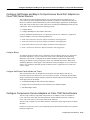
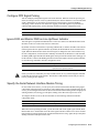
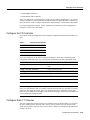
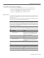
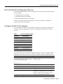
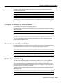
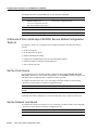
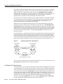
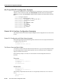
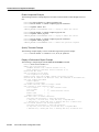
Loopback T1 Channels
You can perform the following types of loopbacks on a T1 channel:
•
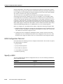
Local—Loops the router output data back toward the router at the T1 framer and sends an AIS
signal out toward the network (see Figure 12).
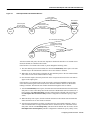
•
Network line—Loops the data back toward the network before the T1 framer and automatically
sets a local loopback (see Figure 13).
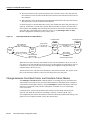
•
Network payload—Loops just the payload data back toward the network at the T1 framer and
automatically sets a local loopback (see Figure 14).
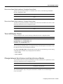
•
Remote line inband—Sends a repeating 5-bit inband pattern (00001) to the remote end
requesting that it enter into a network line loopback (see Figure 15).
To enable loopbacks on a T1 channel, use the first command in global configuration mode, followed
by any one of the following commands:
Command
Purpose
interface serial slot/port-adapter/port:t1-channel
Select the T1 channel (values are 1 to 28) on the CT3IP
and enter interface configuration mode.
loopback local
Enable the local loopback on the T1 channel.
loopback network line
Enable the network line loopback on the T1 channel.
loopback network payload
Enable the network payload loopback on the T1
channel.
loopback remote line inband
Enable the remote line inband loopback on the T1
channel.
Note The port adapter and port numbers for the CT3IP are 0.
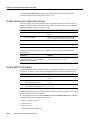
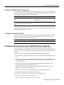
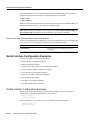
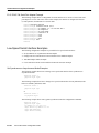
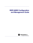
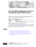
Figure 12 shows an example of a local loopback in which the loopback occurs in the T1 framer.
IC-86
Cisco IOS Interface Configuration Guide
Troubleshoot the T3 and T1 Channels
Figure 12
CT3IP Local Loopback
HDLC
controllers
T1 channels
Controller 1
Channel 1
Controller 2
Channel 2
CT3IP
T3 output
MUX
Channel 28
S5681
Controller 28
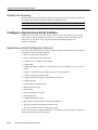
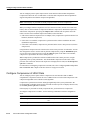
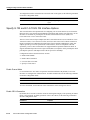
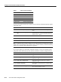
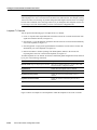
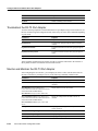
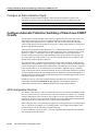
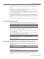
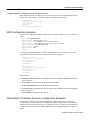
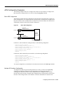
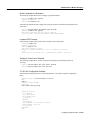
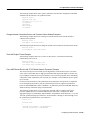
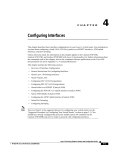
Figure 13 shows an example of a network line loopback in which just the data is looped back toward
the network (before the T1 framer).
Figure 13
CT3IP Network Line Loopback
HDLC
controllers
T1 channels
Controller 1
Channel 1
Controller 2
CT3IP
Channel 2
T3 output
MUX
Channel 28
S5682
Controller 28
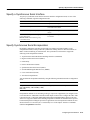
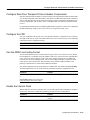
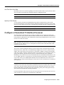
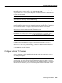
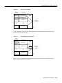
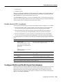
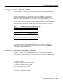
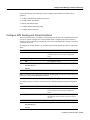
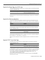
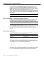
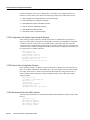
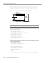
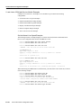
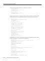
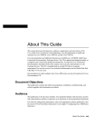
Figure 14 shows an example of a network payload loopback in which just the payload data is looped
back toward the network at the T1 framer.
Configuring Serial Interfaces IC-87
Configure a Channelized T3 Interface Processor
Figure 14
HDLC
controllers
CT3IP Network Payload Loopback
T1 channels
Channel 1
CT3IP
Controller 2
Channel 2
MUX
Controller 28
Channel 28
T3 output
S5683
Controller 1
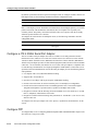
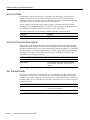
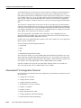
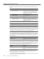
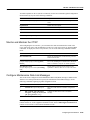
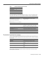
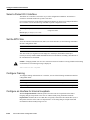
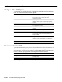
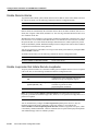
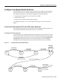
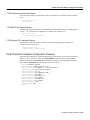
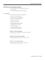
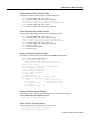
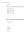
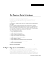
Figure 15 shows an example of a remote inband loopback in which the network line enters a line
loopback.
Figure 15
CT3IP Remote Loopback
HDLC
controllers
T1 channels
Controller 1
Channel 1
CT3IP
Network cloud
Remote
CSU/DSU
T3 output
Channel 2
Controller 28
Channel 28
MUX
S5684
Controller 2
Loopback T3 Lines
You can put the entire T3 line into loopback mode (that is, all T1 channels are looped) by using the
following types of loopbacks:
IC-88
•
Local—Loops the router output data back toward the router at the T1 framer and sends an AIS
signal out toward the network.
•
•
Network—Loops the data back toward the network (before the T1 framer).
Remote —Sends a FEAC (far-end alarm control) request to the remote end requesting that it enter
into a network line loopback. FEAC requests (and therefore remote loopbacks) are only possible
when the T3 is configured for C-bit framing. The type of framing used is determined by the
equipment you are connecting to. (For more information, see the framing controller command.)
Cisco IOS Interface Configuration Guide
Monitor and Maintain the CT3IP
To enable loopbacks on the T3 (and all T1 channels), use the first command in global configuration
mode followed by any one of the following commands:
Command
Purpose
controller t3 slot/port-adapter/port
Select the CT3IP and enter controller configuration
mode.
loopback local
Enable the local loopback.
loopback network
Enable the network loopback.
loopback remote
Enable the remote loopback.
Note The port adapter and port numbers for the CT3IP are 0.
Monitor and Maintain the CT3IP
After configuring the new interface, you can monitor the status and maintain the CT3IP in the
Cisco 7000 series routers with an RSP7000 or in the Cisco 7500 series routers by using the show
commands. To display the status of any interface, use one of the following commands in EXEC
mode:
Command
Purpose
show controller cbus
Display the internal status of each interface processor
and list each interface.
show controller t3
[slot/port-adapter/port[:t1-channel]] [brief |
tabular]
Display the status of the T3 and T1 channels (values
are 1 to 28) including the T3 alarms and T1 alarms for
all 28 T1 channels or only the T1 channel specified.
show interfaces serial
slot/port-adapter/port:t1-channel [accounting |
crb]
Display statistics about the serial interface for the
specified T1 channel (values are 1 to 28) on the router.
Configure Maintenance Data Link Messages
The CT3IP can be configured to send a Maintenance Data Link (MDL) message as defined in the
ANSI T1.107a-1990 specification. To specify the transmission of the MDL messages, use the
following commands beginning in global configuration mode:
Step
Command
Purpose
1
controller t3 slot/port-adapter/port
Select the CT3IP and enter controller configuration
mode.
2
mdl {transmit {path | idle-signal |
test-signal} | string {eic | lic | fic | unit
| pfi | port | generator} string}
Configure the Maintenance Data Link (MDL)
message.
Note Specify one mdl command for each message. For example, use mdl string eic Router A to
transmit “Router A” as the equipment identification code and use mdl string lic Test Network to
transmit “Test Network” as the location identification code.
Configuring Serial Interfaces IC-89
Configure a Channelized T3 Interface Processor
Use the show controllers t3 command to display MDL information (received strings). MDL
information is displayed only when framing is set to C-bit.
Enable Performance Report Monitoring
The CT3IP supports performance reports via the Facility Data Link (FDL) per ANSI T1.403. By
default, performance reports are disabled. To enable FDL performance reports, use the following
commands beginning in global configuration mode:
Step
Command
Purpose
1
controller t3 slot/port-adapter/port
Select the CT3IP and enter controller configuration
mode.
2
t1 channel fdl ansi
Enable one-second transmission of the performance
report for a specific T1 channel (values are 1 to 28).
Note Performance reporting is available only on T1 channels configured for ESF framing.
To display the remote performance report information, use the following command in EXEC
command mode:
Command
Purpose
show controller t3
[slot/port-adapter/port[:t1-channel]] remote
performance [brief | tabular]
Display the remote performance report information for
the T1 channel (values are 1 to 28).
Enable BERT Test Pattern
To enable and disable generation of a bit error rate testing (BERT) test pattern for a specified interval
for a specific T1 channel, use the following commands beginning in global configuration mode:
Step
Command
Purpose
1
controller t3 slot/port-adapter/port
Select the CT3IP and enter controller configuration
mode.
2
t1 channel bert pattern {0s | 1s | 2^15 |
2^20 | 2^23} interval minutes
Enable a BERT test pattern on a T1 channel (values are
1 to 28).
3
no t1 channel bert pattern {0s | 1s |
2^15 | 2^20 | 2^23} interval minutes
Disable a BERT test pattern on a T1 channel (values
are 1 to 28).
The BERT test patterns from the CT3IP are framed test patterns (that is, the test patterns are inserted
into the payload of the framed T1 signal).
To view the BERT results, use the show controller t3 or show controller t3 brief EXEC command.
The BERT results include the following information:
•
•
•
•
IC-90
Type of test pattern selected
Status of the test
Interval selected
Time remaining on the BERT test
Cisco IOS Interface Configuration Guide
Enable Remote FDL Loopbacks
•
•
Total bit errors
Total bits received
When the T1 channel has a BERT test running, the line state is DOWN. Also, when the BERT test
is running and the Status field is Not Sync, the information in the total bit errors field is not valid.
When the BERT test is done, the Status field is not relevant.
The t1 bert pattern command is not written to NVRAM because it is only used for testing the T1
channel for a short predefined interval and to avoid accidentally saving the command, which could
cause the interface not to come up the next time the router reboots.
Enable Remote FDL Loopbacks
You can perform the following types of remote Facility Data Link (FDL) loopbacks on a T1 channel:
•
Remote payload FDL ANSI—Sends a repeating, 16-bit ESF data link code word (00010100
11111111) to the remote end requesting that it enter into a network payload loopback.
•
Remote line FDL ANSI—Sends a repeating, 16-bit ESF data link code word (00001110
11111111) to the remote CSU end requesting that it enter into a network line loopback.
•
Remote line FDL Bellcore—Sends a repeating, 16-bit ESF data link code word (00010010
11111111) to the remote SmartJack end requesting that it enter into a network line loopback.
To enable loopbacks on a T1 channel, use the following commands beginning in global configuration
mode:
Step
Command
Purpose
1
interface serial
slot/port-adapter/port:t1-channel
(Cisco 7500 series and Cisco 7000
series routers with the RSP7000 and
RSP7000CI)
Select the T1 channel (values are 1 to 28) on the CT3IP
and enter interface configuration mode.
or
interface serial slot/port:t1-channel
(Cisco 7200 series)
2
loopback remote payload [fdl] [ansi]
Enable the remote payload FDL ANSI bit loopback on
the T1 channel.
3
loopback remote line fdl {ansi |
bellcore}
Enable the remote line FDL ANSI bit loopback or
remote SmartJack loopback on the T1 channel.
Note The port adapter and port numbers for the CT3IP are 0.
Configure PA-E3 and PA-2E3 Serial Port Adapters
The PA-E3 and PA-2E3 serial port adapters are available on Cisco 7200 series routers, on Cisco 7500
series routers, and on Cisco 7000 series routers with the 7000 Series Route Switch Processor
(RSP7000) and 7000 Series Chassis Interface (RSP7000CI). These port adapters provide one
(PA-E3) or two (PA-2E3) high-speed, full-duplex, synchronous serial E3 interfaces and integrated
data service unit (DSU) functionality.
Configuring Serial Interfaces IC-91
Configure PA-E3 and PA-2E3 Serial Port Adapters
The E3 port adapters can transmit and receive data at E3 rates of up to 34 Mbps and use a 75-ohm
coaxial cable available from Cisco to connect to a serial E3 network. These port adapters support the
following:
•
•
•
•
•
•
•
•
•
16- and 32-bit cyclic redundancy checks (CRC)
High-speed HDLC data
G.751 framing or bypass
HDB3 line coding
ATM-DXI, Frame Relay, HDLC, PPP, and SMDS serial encapsulation
National service bits
E3 MIB (RFC 1407)
Scrambling and reduced bandwidth
Remote and local loopbacks
The PA-E3 port adapter supports a subset of RFC 1407 MIB. We support DS3 Near End Group
including—DS3/E3 Configuration Table, DS3/E3 Current Table, DS3/E3 Interval Table, and
DS3/E3 Total Table. We do not support DS3 Far End Group and DS3/E3 Fractional Group. The
PA-E3 port adapter also supports the Card Table in the Cisco Chassis MIB and the MIB-2 for each
PA-E3 interface.
Note For additional information on E3 serial port adapter, refer to the PA-E3 Serial Port Adapter
Installation and Configuration publication.
PA-E3 and PA-2E3 Serial Port Adapter Configuration Task List
Perform the tasks in the following sections to configure the PA-E3. The first task is required; all other
tasks are optional:
•
•
•
Configure the PA-E3 Port Adapter
Troubleshoot the PA-E3 Port Adapter
Monitor and Maintain the PA-E3 Port Adapter
For PA-E3 port adapter configuration examples, see the “PA-E3 Serial Port Adapter Configuration
Example” section, later in this chapter.
Configure the PA-E3 Port Adapter
The commands listed in Table 7 have been added to support the PA-E3 interface configuration.
If you do not modify the configuration of the PA-E3, the configuration defaults shown in Table 7 are
used.
Table 7
IC-92
PA-E3 Port Adapter Defaults
Command
Default Value
dsu bandwidth
34010 kbps
dsu mode
0
framing
g751
Cisco IOS Interface Configuration Guide
Troubleshoot the PA-E3 Port Adapter
Table 7
PA-E3 Port Adapter Defaults (continued)
Command
Default Value
international bit
00
invert data
data is not inverted
national bit
0
scramble
disabled
If you need to change any of the default configuration attributes, use the first command in global
configuration mode, followed by any of the optional commands in interface configuration mode:
Command
Purpose
interface serial slot/port-adapter/port
(Cisco 7500 series and Cisco 7000 series routers
with the RSP7000 and RSP7000CI)
Select the PA-E3 interface and enter interface
configuration mode.
or
interface serial slot/port (Cisco 7200 series)
dsu bandwidth kbps
Change the DSU bandwidth.
dsu mode {0 | 1}
Change the DSU mode. To connect to another PA-E3
port adapter or a Digital Link DSU, use the default
mode (0). To connect to a Kentrox DSU, use mode 1.
framing {g751 | bypass}
Change the framing used by the interface.
international bit {0 | 1} {0 | 1}
Change the international bit used by the interface.
invert data
Invert the data stream on the interface.
national bit {0 | 1}
Change the national bit used by the interface.
scramble
Enable scrambling on the interface.
Troubleshoot the PA-E3 Port Adapter
To set the following loopbacks to troubleshoot the PA-E3 port adapter using Cisco IOS software, use
the first command in global configuration mode, followed by any of the other commands, depending
on your needs:
Command
Purpose
loopback dte
Loopback after the LIU toward the terminal.
loopback local
Loopback after going through the framer toward the
terminal.
loopback network line
Loopback toward the network before going through the
framer.
loopback network payload
Loopback toward the network after going through the
framer.
These loopback commands loop all packets from the E3 interface back to the interface and also
direct the packets to the network.
Configuring Serial Interfaces IC-93
Configure PA-T3 and PA-2T3 Serial Port Adapters
Monitor and Maintain the PA-E3 Port Adapter
After configuring the new interface, you can display its status. To show current status of the E3
interface on the PA-E3 port adapter, use any of the following commands in EXEC mode:
Command
Purpose
show interfaces serial slot/port-adapter/port
(Cisco 7500 series and Cisco 7000 series routers
with the RSP7000 and RSP7000CI)
Display statistics for the E3 interface.
or
show interfaces serial slot/port (Cisco 7200
series)
show controllers serial slot/port-adapter/port
(Cisco 7500 series and Cisco 7000 series routers
with the RSP7000 and RSP7000CI)
Display the configuration information for the E3
interface.
or
show controllers serial slot/port (Cisco 7200
series)
Configure PA-T3 and PA-2T3 Serial Port Adapters
The PA-T3 and PA-2T3 serial port adapters are available on Cisco 7200 series routers, on
second-generation Versatile Interface Processor (VIP2) in all Cisco 7500 series routers, and on Cisco
7000 series routers with the 7000 Series Route Switch Processor (RSP7000) and 7000 Series Chassis
Interface (RSP7000CI). These port adapters provide one (PA-T3) or two (PA-2T3) high-speed,
full-duplex, synchronous serial T3 interfaces and integrated data service unit (DSU) functionality.
The T3 port adapters can transmit and receive data at T3 rates of up to 45 Mbps and use a 75-ohm
coaxial cable available from Cisco to connect to a serial T3 network. These port adapters support the
following features:
•
•
•
•
•
•
•
•
16- and 32-bit cyclic redundancy checks (CRC)
High-speed HDLC data
C-bit, M13, and bypass framing
HDB3 line coding
ATM-DXI, Frame Relay, HDLC, PPP, and SMDS serial encapsulation
DS3 MIB (RFC 1407)
Scrambling and reduced bandwidth
Remote and local loopbacks
Note For additional information on interoperability guidelines for T3 serial port adapter DSUs,
refer to the PA-T3 Serial Port Adapter Installation and Configuration publication.
IC-94
Cisco IOS Interface Configuration Guide
PA-T3 and PA-2T3 Configuration Task List
PA-T3 and PA-2T3 Configuration Task List
Perform the tasks in the following sections to configure the PA-T3 (The first task is required; all other
tasks are optional.):
•
•
•
Configure the PA-T3 Port Adapter
Troubleshoot the PA-T3 Port Adapter
Monitor and Maintain the PA-T3 Port Adapter
For PA-T3 port adapter configuration examples, see the “PA-T3 and PA-2T3 Configuration
Example” section, later in this chapter.
Configure the PA-T3 Port Adapter
The commands listed in Table 8 have been added to support the PA-T3 interface configuration. If
you do not modify the configuration of the PA-T3, the configuration defaults shown in Table 8
are used.
Table 8
PA-T3 Port Adapter Defaults
Command
Default Value
cablelength
50
clock source
line
crc 32
16-bit
dsu bandwidth
44736 kbps
dsu mode
0
framing
C-bit
invert data
data is not inverted
scramble
disabled
If you need to change any of the default configuration attributes, use the first command in global
configuration mode, followed by any of the optional commands in interface configuration mode:
Command
Purpose
interface serial slot/port-adapter/port
(Cisco 7500 series and Cisco 7000 series routers
with the RSP7000 and RSP7000CI)
Select the PA-T3 interface and enter interface
configuration mode.
or
interface serial slot/port (Cisco 7200 series)
cablelength length
Change the cable length.
crc 32
Enable 32-bit CRC.
dsu bandwidth kbps
Change the DSU bandwidth.
dsu mode {0 | 1 | 2}
Change the DSU mode. To connect to another PA-T3
port adapter or a Digital Link DSU, use the default
mode (0). To connect to a Kentrox DSU, use mode 1.
To connect to a Larscom DSU, use mode 2.
framing {c-bit | m13 | bypass}
Change the framing used by the interface.
Configuring Serial Interfaces IC-95
Configure PA-T3 and PA-2T3 Serial Port Adapters
Command
Purpose
invert data
Invert the data stream on the interface.
scramble
Enable scrambling on the interface.
Troubleshoot the PA-T3 Port Adapter
To set the following loopbacks to troubleshoot the PA-T3 port adapter using Cisco IOS software, use
the first command in global configuration mode, followed by any of the other commands depending
on your needs:
Command
Purpose
loopback dte
Loopback after the LIU toward the terminal.
loopback local
Loopback after going through the framer toward the
terminal.
loopback network line
Loopback toward the network before going through the
framer.
loopback network payload
Loopback toward the network after going through the
framer.
loopback remote
Send a FEAC to set the remote framer in loopback.
These loopback commands loop all packets from the T3 interface either back to the interface or
direct packets from the network back out toward the network.
Monitor and Maintain the PA-T3 Port Adapter
After configuring the new interface, you can display its status. To show current status of the T3
interface on the PA-T3 port adapter, use any of the following commands in EXEC mode:
Command
Purpose
show version
Display system hardware configuration.
show controllers cbus
Display current interface processors and their
interfaces.
show interfaces slot/port-adapter/port
(Cisco 7500 series and Cisco 7000 series routers
with the RSP7000 and RSP7000CI)
Display statistics for the T3 interface.
show interfaces slot/port (Cisco 7200 series)
show controllers serial slot/port-adapter/port
(Cisco 7500 series and Cisco 7000 series routers
with the RSP7000 and RSP7000CI)
Display the configuration information for the T3
interface.
show controllers serial slot/port (Cisco 7200
series)
IC-96
show protocols
Display protocols configured for the system and
specific interfaces.
more system:running-config
Display running configuration file.
more nvram:startup-config
Display configuration stored in NVRAM.
show diag slot
Display specific port adapter information
Cisco IOS Interface Configuration Guide
Configure a Packet OC-3 Interface
Configure a Packet OC-3 Interface
The Cisco Packet OC-3 Interface Processor (POSIP) and Packet OC-3 Port Adapter (POSPA) are
available on Cisco 7200 and Cisco 7500 series routers.
The POS is a fixed-configuration interface processor that uses second-generation Versatile Interface
Processor (VIP2) technology. The POS provides a single 155.520-Mbps, OC-3 physical layer
interface for packet-based traffic. This OC-3 interface is fully compatible with SONET and
Synchronous Digital Hierarchy (SDH) network facilities and is compliant with RFC 1619, “PPP
over SONET/SDH,” and RFC 1662, “PPP in HDLC-like Framing.” The Packet-Over-SONET
specification is primarily concerned with the use of the PPP encapsulation over SONET/SDH links.
Table 9 describes the default values set in the initial configuration of a Packet OC-3 interface.
Table 9
Packet OC-3 Interface Default Configuration
Attributes
Default Value
Maximum transmission unit
(MTU)
4470 bytes
Framing
SONET STS-3c framing
Loopback internal
No internal loopback
Loopback line
No line loopback
Transmit clocking
Recovered receive clock
Enabling
Shut down
Because the Packet OC-3 interface is partially configured, you might not need to change its
configuration before enabling it. However, when the router is powered up, a new Packet OC-3
interface is shut down. To enable the Packet OC-3 interface, you must use the no shutdown
command in the global configuration mode.
Packet OC-3 Interface Configuration Task List
The values of all Packet OC-3 configuration parameters can be changed to match your network
environment. Perform the optional tasks in the following sections if you need to customize the POS
configuration:
•
•
•
•
•
•
•
•
Select a Packet OC-3 Interface
Set the MTU Size
Configure Framing
Configure an Interface for Internal Loopback
Configure an Interface for Line Loopback
Set the Source of the Transmit Clock
Enable Payload Scrambling
Configure an Alarm Indication Signal
Configuring Serial Interfaces IC-97
Configure a Packet OC-3 Interface
Select a Packet OC-3 Interface
The Packet OC-3 interface is referred to as pos in the configuration commands. An interface is
created for each POS found in the system at reset time.
If you need to change any of the default configuration attributes or otherwise reconfigure the Packet
OC-3 interface, use one the following commands in global configuration mode:
Command
Purpose
interface pos slot/port (Cisco 7200)
Select the Packet OC-3 interface and enter interface
configuration mode.
or
interface pos port-adapter (Cisco 7500)
Set the MTU Size
To set the maximum transmission unit (MTU) size for the interface, use the following command in
interface configuration mode:
Command
Purpose
mtu bytes
Set the MTU size.
The value of the bytes argument is in the range 64 to 4470 bytes; the default is 4470 bytes.
(4470 bytes exactly matches FDDI and HSSI interfaces for autonomous switching.) The no form of
the command restores the default.
Caution Changing an MTU size on a Cisco 7500 series router will result in recarving of buffers and resetting
of all interfaces. The following message is displayed:
%RSP-3-Restart:cbus complex88
Configure Framing
To configure framing on the Packet OC-3 interface, use one of the following commands in interface
configuration mode:
Command
Purpose
pos framing-sdh
Select SDH STM-1 framing.
no pos framing-sdh
Revert to the default SONET STS-3c framing.
Configure an Interface for Internal Loopback
With the loopback internal command, packets from the router are looped back in the framer.
Outgoing data gets looped back to the receiver without actually being transmitted. With the
loopback line command, the receive (RX) fiber is logically connected to the transmit fiber (TX) so
that packets from the remote router are looped back to it. Incoming data gets looped around and
retransmitted without actually being received.
IC-98
Cisco IOS Interface Configuration Guide
Configure an Interface for Line Loopback
To enable or disable internal loopback on the interface, use one of the following commands in
interface configuration mode:
Command
Purpose
loop internal
Enable internal loopback.
no loop internal
Disable internal loopback.
Local loopback is useful for checking that the POS is working. Packets from the router are looped
back in the framer.
Configure an Interface for Line Loopback
Line loopback is used primarily for debugging purposes.
To enable or disable an interface for line loopback, use one of the following commands in interface
configuration mode:
Command
Purpose
loop line
Enable line loopback.
no loop line
Disable line loopback.
The receive fiber (RX) is logically connected to the transmit fiber (TX) so that packets from the
remote router are looped back to it.
Set the Source of the Transmit Clock
By default, the Packet OC-3 interface uses the recovered receive clock to provide transmit clocking.
To change the transmit clock source, use one of the following commands in interface
configuration mode:
Command
Purpose
clock source
Set the internal clock as the transmit clock source.
no clock source
Set the recovered receive clock to provide transmit
clocking.
Enable Payload Scrambling
SONET payload scrambling applies a self-synchronous scrambler (x^43+1) to the Synchronous
Payload Envelope (SPE) of the interface to ensure sufficient bit transition density. Both ends of the
connection must use the same scrambling algorithm. When enabling POS scrambling on a VIP2
POS on the Cisco 7500 series that has a hardware revision of 1.5 or higher, you can specify CRC 16
only (that is, CRC 32 is currently not supported).
To enable SONET payload scrambling on a POS interface, use the following command in interface
configuration mode.
Command
Purpose
pos scramble-atm
Enable SONET payload scrambling.
Configuring Serial Interfaces IC-99
Configure Automatic Protection Switching of Packet-over-SONET Circuits
Configure an Alarm Indication Signal
To configure line alarm indication signals (LAIS) when the POS interface is placed in any
administrative shut down state, use the following command in interface configuration mode:
Command
Purpose
pos ais-shut
Send line alarm indication signals.
Configure Automatic Protection Switching of Packet-over-SONET
Circuits
The automatic protection switching (APS) feature is supported on Cisco 7500 series routers. This
feature allows switchover of packet-over-SONET (POS) circuits and is often required when
connecting SONET equipment to telco equipment. APS refers to the mechanism of bringing a
“protect” POS interface into the SONET network as the “working” POS interface on a circuit from
the intervening SONET equipment.
The protection mechanism used for this feature is “1+1, Bidirectional, nonrevertive” as described in
the Bellcore publication “TR-TSY-000253, SONET Transport Systems; Common Generic Criteria,
Section 5.3.” In the 1+1 architecture, there is one working interface (circuit) and one protect
interface, and the same payload from the transmitting end is sent to both the receiving ends. The
receiving end decides which interface to use. The line overhead (LOH) bytes (K1 and K2) in the
SONET frame indicate both status and action.
The protect interface is configured with the IP address of the router that has the working interface.
The APS Protect Group Protocol, which runs on top of UDP, provides communication between the
process controlling the working interface and the process controlling the protect interface. Using this
protocol, POS interfaces can be switched due to a router failure, degradation or loss of channel
signal, or manual intervention. In bidirectional mode, the receive and transmit channels are switched
as a pair. In unidirectional mode, the transmit and receive channels are switched independently. For
example, if the receive channel on the working interface has a loss of channel signal, both the receive
and transmit channels are switched.
In addition to the new Cisco IOS commands added for the APS feature, the POS interface
configuration commands pos threshold and pos report have been added to support user
configuration of the bit error rate (BER) thresholds and reporting of SONET alarms.
APS Configuration Task List
Two SONET connections are required to support APS. In a telco environment, the SONET circuits
must be provisioned as APS. You must also provision the operation (for example, 1+1), mode (for
example, bidirectional), and revert options (for example, no revert). If the SONET connections are
homed on two separate routers (the normal configuration), an out of band (OOB) communications
channel between the two routers needs to be set up for APS communication.
When configuring APS, we recommend you configure the working interface first. Normal operation
with 1+1 operation is to configure it as a working interface. Also configure the IP address of the
interface being used as the APS OOB communications path.
For more information on POS interfaces, refer to the installation and configuration documentation
that accompanies the POS hardware.
IC-100
Cisco IOS Interface Configuration Guide
Configure APS Working and Protect Interfaces
Perform the first task in the following section to configure APS and POS (The other tasks are
optional.):
•
•
•
•
•
Configure APS Working and Protect Interfaces
Configure Other APS Options
Monitor and Maintain APS
Configure SONET Alarm Reporting
Configure Protection Switch
Configure APS Working and Protect Interfaces
This section describes how to configure a working and protect interface. The commands listed in this
section are required. Configure the working interface before configuring the protect interface to
avoid the protect interface from becoming the active circuit and disabling the working circuit when
it is finally discovered.
To configure the working interface, use the following commands beginning in global configuration
mode:
Step
Command
Purpose
1
interface pos slot/port-adapter/port
Specify the POS interface to be configured as the
working interface and enter interface configuration
mode.
2
aps working circuit-number
Configure this interface as a working interface.
3
end
Exit configuration mode.
4
show controller pos
Verify that the interface is configured correctly.
show interface pos
show aps
Note If a router has two or more protect interfaces, the aps group command for each interface must
precede the corresponding aps protect command.
To configure the protect interface, use the following commands beginning in global configuration
mode:
Step
Command
Purpose
1
interface pos slot/port-adapter/port
Specify the POS interface to be configured as the
protect interface and enter interface configuration
mode.
2
aps protect circuit-number ip-address
Configure this interface as a protect interface. Specify
the IP address of the router that contains the working
interface.
3
end
Exit configuration mode.
4
show controller pos
Verify that the interface is configured correctly.
show interface pos
show aps
Configuring Serial Interfaces IC-101
Configure Automatic Protection Switching of Packet-over-SONET Circuits
Configure Other APS Options
To configure the other APS options, use any of the following commands in interface configuration
mode. The commands listed in this section are optional.
Command
Purpose
aps authenticate string
Enable authentication and specify the string that must
be present to accept any packet on the OOB
communication channel.
aps force circuit-number
Manually switch the specified circuit to a protect
interface, unless a request of equal or higher priority is
in effect.
aps group group-number
Allow more than one protect/working interface group
to be supported on a router.
aps lockout circuit-number
Prevent a working interface from switching to a protect
interface.
aps manual circuit-number
Manually switch a circuit to a protect interface, unless
a request of equal or higher priority is in effect.
aps revert minutes
Enable automatic switchover from the protect interface
to the working interface after the working interface
becomes available.
aps timers seconds1 seconds2
Change the time between hello packets and the time
before the protect interface process declares a working
interface’s router to be down (that is, seconds1 for the
hello time, and seconds2 for the hold time).
aps unidirectional
Configure a protect interface for unidirectional mode.
Monitor and Maintain APS
To provide information about system processes, the Cisco IOS software includes an extensive list of
EXEC commands that begin with the word show, which, when executed, display detailed tables of
system information. Following is a list of some of the common show commands for the APS feature.
Use these commands in privileged EXEC mode to display the information described:
IC-102
Command
Purpose
show aps
Display information about the automatic protection
switching feature.
show controllers pos
Display information about the hardware.
show interface pos
Display information about the interface.
Cisco IOS Interface Configuration Guide
Configure SONET Alarm Reporting
Configure SONET Alarm Reporting
To configure the thresholds and the type of SONET alarms that are reported, use any of the following
commands in interface configuration mode. The commands listed in this section are optional. The
default settings are adequate for most POS installations.
Command
Purpose
pos threshold {b1-tca | b2-tca | b3-tca | sd-ber |
sf-ber} rate
Configure the BER threshold values for signal failure
(SF), signal degrade (SD), or threshold crossing alarms
alarms (TCA).
pos report {b1-tca | b2-tca | b3-tca | lais | lrdi |
pais | plop | prdi | rdool | sd-ber | sf-ber | slof |
slos}
Enable reporting of selected SONET alarms.
To display the current BER threshold setting or to view the reporting of the SONET alarms, use the
show controllers pos EXEC command.
Configure Protection Switch
Line alarm indication signal (LAIS) can be used to force a protection switch in an APS environment.
To force an APS switch when the interface is placed in administrative shut down state, use the
following command in interface configuration mode:
Command
Purpose
pos ais-shut
Send line alarm indication signals.
Configure Serial Interfaces for CSU/DSU Service Modules
The Cisco T1 data service unit/channel service unit (DSU/CSU) WAN interface card is an
integrated, managed T1 or fractional T1 WAN interface card. It provides nonchannelized data rates
of 1 to 24 X 64 kbps or 1 to 24 X 56 kbps and follows ANSI T1.403 and AT&T Publication 62411
standards.
The Cisco DSU/CSU WAN T1 interface management features include the following:
•
You can remotely configure the interface using Telnet and the Cisco IOS command line interface
(CLI).
•
For monitoring purposes, the router and DSU/CSU are manageable as a single Simple Network
Management Protocol (SNMP) entity using CiscoWorks or CiscoView. DSU/CSU statistics are
accessed from the CLI.
•
The SNMP agent supports the standard Management Information Base II (MIB II), Cisco
integrated DSU/CSU MIB, and T1 MIB (RFC 1406).
•
Loopbacks (including a manual button for a network line loopback) and bit error rate tester
(BERT) tests are provided for troubleshooting.
•
•
Test patterns, alarm counters, and performance reports are accessible using the CLI.
The module has carrier detect, loopback, and alarm LEDs.
The following CSU and DSU service modules are described in this section:
•
•
Fractional T1/FT/WIC CSU/DSU service module
2-Wire and 4-Wire, 56/64-kbps CSU/DSU service module
Configuring Serial Interfaces IC-103
Configure Serial Interfaces for CSU/DSU Service Modules
Fractional T1/FT/WIC CSU/DSU Service Module Configuration Task List
To configure fractional T1 and T1 (FT1/T1) service modules, perform the tasks described in these
sections:
•
•
•
•
•
•
•
•
•
Specify the Clock Source
Enable Data Inversion before Transmission
Specify the Frame Type of a FT/T1 Line
Specify the CSU Line Build Out
Specify FT1/T1 Line-Code Type
Enable Remote Alarms
Enable Loopcodes that Initiate Remote Loopbacks
Specify Timeslots
Enable T1 CSU WIC
Specify the Clock Source
To specify the clock source for the FT1/T1 CSU/DSU module, use the following command in
interface configuration mode:
Command
Purpose
service-module t1 clock source {internal | line}
Specify the clock source, for the CSU/DSU internal
clock or the line clock.
Enable Data Inversion before Transmission
Data inversion is used to guarantee the ones density requirement on an alternate mark inversion
(AMI) line when using bit-oriented protocols such as High-Level Data Link Control (HDLC),
Point-to-Point Protocol (PPP), X.25, and Frame Relay.
To guarantee the ones density requirement on an AMI line using the FT1/T1 CSU/DSU module, use
the following command in interface configuration mode:
Command
Purpose
service-module t1 data-coding inverted
Invert bit codes by changing all 1 bits to 0 bits and all 0
bits to 1 bits.
If the timeslot speed is set to 56 kbps, this command is rejected because line density is guaranteed
when transmitting at 56 kbps. Use this command with the 64-kbps line speed. If you transmit
inverted bit codes, both CSU/DSUs must have this command configured for successful
communication.
To enable normal data transmission on a FT1/T1 network, use the following command in interface
configuration mode:
Command
Purpose
service-module tx1 data-coding normal
Enable normal data transmission on a T1 network.
or
no service-module t1 data-coding inverted
IC-104
Cisco IOS Interface Configuration Guide
Specify the Frame Type of a FT/T1 Line
Specify the Frame Type of a FT/T1 Line
To specify the frame type for a line using the FT1/T1 CSU/DSU module, use the following command
in interface configuration mode:
Command
Purpose
service-module t1 framing {sf | esf}
Specify a FT1/T1 frame type. Choose either D4 Super
Frame (sf) or Extended Super Frame (esf).
In most cases, the service provider determines which framing type, either esf or sf, is required for
your circuit.
Specify the CSU Line Build Out
To decrease the outgoing signal strength to an optimum value for the telecommunication carrier
network, use the following command on the FT1/T1 CSU/DSU module in interface configuration
mode:
Command
Purpose
service-module t1 lbo {-15 db | -7.5 db}
Decrease the outgoing signal strength in decibels.
To transmit packets without decreasing outgoing signal strength, use the following command in
interface configuration mode:
Command
Purpose
service-module t1 lbo none
Transmits packets without decreasing outgoing
signal strength.
The ideal signal strength should be between –15 dB and –22 dB, which is calculated by adding the
phone company loss + cable length loss + line build out.
You may use this command in back-to-back configurations, but it is not needed on most actual T1
lines.
Specify FT1/T1 Line-Code Type
To configure the line code for the FT1/T1 CSU/DSU module, use the following command in
interface configuration mode:
Command
Purpose
service-module t1 linecode {ami | b8zs}
Specify a line-code type. Choose alternate mark
inversion (AMI) or binary 8 zero substitution (B8ZS).
Configuring B8ZS is a method of ensuring the ones density requirement on a T1 line by substituting
intentional bipolar violations in bit positions four and seven for a sequence of eight zero bits. When
the CSU/DSU is configured for AMI, you must guarantee the ones density requirement in your
router configuration using the service-module t1 data-coding inverted command or the
service-module t1 timeslots speed 56 command.
In most cases, your T1 service provider determines which line-code type, either ami or b8zs, is
required for your T1 circuit.
Configuring Serial Interfaces IC-105
Configure Serial Interfaces for CSU/DSU Service Modules
Enable Remote Alarms
To generate remote alarms (yellow alarms) at the local CSU/DSU or detect remote alarms sent from
the remote CSU/DSU, use the following command in interface configuration mode:
Command
Purpose
service-module t1 remote-alarm-enable
Enable remote alarms.
Remote alarms are transmitted by the CSU/DSU when it detects an alarm condition, such as a red
alarm (loss of signal) or blue alarm (unframed 1’s). The receiving CSU/DSU then knows there is an
error condition on the line.
With D4 super frame configured, a remote alarm condition is transmitted by setting the bit 2 of each
time slot to zero. For received user data that has the bit 2 of each time slot set to zero, the CSU/DSU
interprets the data as a remote alarm and interrupts data transmission, which explains why remote
alarms are disabled by default. With Extended Super Frame configured, the remote alarm condition
is signalled out of band in the facility data link.
You can see if the FT1/T1 CSU/DSU is receiving a remote alarm (yellow alarm) by issuing the show
service-module command.
To disable remote alarms, use the following command in interface configuration mode:
Command
Purpose
no service-module t1 remote-alarm-enable
Disable remote alarms.
Enable Loopcodes that Initiate Remote Loopbacks
To specify if the fractional T1/T1 CSU/DSU module goes into loopback when it receives a loopback
code on the line, use the following commands in interface configuration mode:
Step
Command
Purpose
1
service-module t1 remote-loopback
full
Configures the remote loopback code used to
transmit or accept CSU loopback requests.
2
service-module t1 remote-loopback
payload [alternate | v54]
Configures the loopback code used by the local
CSU/DSU to generate or detect
payload-loopback commands.
Note By using the service-module t1 remote-loopback command without specifying any
keywords, you enable the standard-loopup codes, which use a 1-in-5 pattern for loopup and a 1-in-3
pattern for loopdown.
You can simultaneously configure the full and payload loopback points. However, only one
loopback payload code can be configured at a time. For example, if you configure the
service-module t1 remote-loopback payload alternate command, a payload v.54 request, which
is the industry standard and default, cannot be transmitted or accepted. Full and payload loopbacks
with standard-loopup codes are enabled by default.
IC-106
Cisco IOS Interface Configuration Guide
Specify Timeslots
The no form of this command disables loopback requests. For example, the no service-module t1
remote-loopback full command ignores all full-bandwidth loopback transmissions and requests.
Configuring the no form of the command may not prevent telco line providers from looping your
router in esf mode, because fractional T1/T1 telcos use facilities data-link messages to initiate
loopbacks.
If you enable the service-module t1 remote-loopback command, the loopback remote commands
on the FT1/T1 CSU/DSU module will not be successful.
Specify Timeslots
To define timeslots for FT1/T1 module, use the following command in interface configuration mode:
Command
Purpose
service-module t1 timeslots {range | all} [speed
{56 | 64}]
Specify timeslots.
This command specifies which timeslots are used in fractional T1 operation and determines the
amount of bandwidth available to the router in each timeslot. The range specifies the DS0 timeslots
that constitute the FT1/T1 channel. The range is from 1 to 24, where the first timeslot is numbered
1, and the last timeslot is numbered 24. Specify this field by using a series of subranges separated by
commas. The timeslot range must match the timeslots assigned to the channel group. In most cases,
the service provider defines the timeslots that comprise a channel group. Use the no form of this
command to select all FT1/T1 timeslots transmitting at 64 kbps, which is the default.
To use the entire T1 line, enable the service-module T1 timeslots all command.
Enable T1 CSU WIC
The following are prerequisites to enable the T1 CSU WIC:
•
•
Leased line from your telephone company
Configuration parameters depending on your specific telephone company. For most connections,
the default settings should suffice:
— service-module t1 clock source line
— service-module t1 data-coding normal
— service-module t1 timeslots all speed 64
— service-module t1 framing esf
— service-module t1 lbo none
— service-module t1 linecode b8zs
— no service-module t1 remote-alarm-enable
— no service-module t1 fdl
Note To view the current configuration, use the show service-module serial slot/port command.
For further information about these commands and how to change them, refer to the Cisco IOS
configuration guides and command references that shipped with your router.
Configuring Serial Interfaces IC-107
Configure Serial Interfaces for CSU/DSU Service Modules
To configure the router to send SNMP traps, use the following commands:
Step
Command
Purpose
interface serial slot/port
Enter interface configuration mode.
(slot/port corresponds to where the
WIC card is installed in your router)
service-module t1 fdl {ansi | att}
Set the fdl parameter to either ansi or att.
<Ctrl-z>
Exit interface configuration mode.
more system:running-config
Verify that the fdl parameter has been changed.
2-Wire and 4-Wire, 56/64-kbps CSU/DSU Service Module Configuration
Task List
To configure 2- and 4-wire, 56/64 kbps service modules, perform the tasks described in these
sections:
•
•
•
•
•
•
Set the Clock Source
Set the Network Line Speed
Enable Scrambled Data Coding
Change between Digital Data Service and Switched Dial-Up Modes
Enable Acceptance of a Remote Loopback Request
Select a Service Provider
Set the Clock Source
In most applications, the CSU/DSU should be configured with the service-module 56k clock
source line command. For back-to-back configurations, use the internal keyword to configure one
CSU/DSU and use the line keyword to configure the other CSU/DSU.
To configure the clock source for a 4-wire, 56/64-kbps CSU/DSU module, use the following
command for a serial interface in interface configuration mode:
Command
Purpose
service-module 56k clock source {line |
internal}
Configure the clock source.
Use the no form of this command to revert to the default clock source, which is the line clock.
Set the Network Line Speed
To configure the network line speed for a 4-wire, 56/64-kbps CSU/DSU module, use the following
command for a serial interface in interface configuration mode:
IC-108
Command
Purpose
service-module 56k clock rate speed
Set the network line speed.
Cisco IOS Interface Configuration Guide
Enable Scrambled Data Coding
You can use the following line speed settings: 2.4, 4.8, 9.6, 19.2, 38.4, 56, 64 kpbs, and an auto
setting.
The 64-kbps line speed cannot be used with back-to-back digital data service (DDS) lines. The
subrate line speeds are determined by the service provider.
Only the 56-kbps line speed is available in switched mode. Switched mode is the default on the
2-wire CSU/DSU and is enabled by the service-module 56k network-type interface configuration
command on the 4-wire CSU/DSU.
The auto linespeed setting enables the CSU/DSU to decipher current line speed from the sealing
current running on the network. Because back-to-back DDS lines do not have sealing current, use
the auto setting only when transmitting over telco DDS lines and using the line clock as the clock
source.
Use the no form of this command to enable a network line speed of 56 kbps, which is the default.
Enable Scrambled Data Coding
To prevent application data from replicating loopback codes when operating at 64-kbps on a 4-wire
CSU/DSU, use the following command for a serial interface in interface configuration mode:
Command
Purpose
service-module 56k data-coding scrambled
Scramble bit codes before transmission.
Enable the scrambled configuration only in 64-kbps digital data service (DDS) mode. If the network
type is set to switched, the configuration is refused.
If you transmit scrambled bit codes, both CSU/DSUs must have this command configured for
successful communication.
To enable normal data transmission for the 4-wire, 56/64-kbps module, use one of the following
commands for a serial interface in interface configuration mode:
Command
Purpose
service-module 56k data-coding normal
Specify normal data transmission.
or
no service-module 56k data-coding
Change between Digital Data Service and Switched Dial-Up Modes
To transmit packets in Digital Data Service (DDS) mode or switched dial-up mode using the 4-wire,
56/64-kbps CSU/DSU module, use one of the following commands for a serial interface in interface
configuration mode:
Command
Purpose
service-module 56k network-type dds
Transmit packets in switched dial-up mode or DDS
mode.
or
service-module 56k network-type switched
Use the no form of these commands to transmit from a dedicated leased line in DDS mode. DDS is
enabled by default for the 4-wire CSU/DSU. Switched is enabled by default for the 2-wire
CSU/DSU.
Configuring Serial Interfaces IC-109
Configure Serial Interfaces for CSU/DSU Service Modules
In switched mode, you need additional dialer configuration commands to configure dial-out
numbers. Before you enable the service-module 56k network-type switched command, both
CSU/DSU’s must use a clock source coming from the line and the clock rate configured to auto or
56k kbps. If the clock rate is not set correctly, this command will not be accepted.
The 2-wire and 4-wire, 56/64-kbps CSU/DSU modules use V.25 bis dial commands to interface with
the router. Therefore, the interface must be configured using the dialer in-band command. DTR dial
is not supported.
Note Any loopbacks in progress are terminated when switching between modes.
Enable Acceptance of a Remote Loopback Request
To enable the acceptance of a remote loopback request on a 2- or 4-wire, 56/64-kbps CSU/DSU
module, use the following command for a serial interface in interface configuration mode:
Command
Purpose
service-module 56k remote-loopback
Enable a remote loopback request.
The no service-module 56k remote-loopback command prevents the local CSU/DSU from being
placed into loopback by remote devices on the line. Unlike the T1 module, the 2- or 4-wire,
56/64-kbps CSU/DSU module can still initiate remote loopbacks with the no form of this command
configured.
Select a Service Provider
To select a service provider to use with a 2- or 4-wire, 56/64 kbps dial-up line, use the following
command for a serial interface in interface configuration mode:
Command
Purpose
service-module 56k switched-carrier {att |
other | sprint}
Select a service provider for a 2 or 4 wire switched
56/64 kbps dialup line.
The att keyword specifies AT&T or another digital network service provider as the line carrier,
which is the default for the 4-wire, 56/64-kbps CSU/DSU module. The sprint keyword specifies
Sprint or another service provider whose network carries mixed voice and data as the line carrier,
which is the default for the 2-wire switched 56-kbps CSU/DSU module.
In a Sprint network, echo-canceler tones are sent during call setup to prevent echo cancelers from
damaging digital data. The transmission of these cancelers may increase call setup times by
8 seconds on the 4-wire module. Having echo cancellation enabled does not affect data traffic.
This configuration command is ignored if the network type is DDS.
Use the no form of this command to enable the default service provider. AT&T is enabled by default
on the 4-wire, 56/64 module. Sprint is enabled by default on the 2-wire switched 56 module.
IC-110
Cisco IOS Interface Configuration Guide
Configure Low-Speed Serial Interfaces
Configure Low-Speed Serial Interfaces
This section describes how to configure low-speed serial interfaces. In addition to the background
information described in the “Understand Half-Duplex DTE and DCE State Machines” section,
these configuration guidelines are provided for configuring low-speed serial interfaces:
•
•
•
Change between Controlled-Carrier and Constant-Carrier Modes
Tune Half-Duplex Timers
Change between Synchronous and Asynchronous Modes
For configuration Examples, see the “APS Configuration Examples” section at the end of this
chapter.
Understand Half-Duplex DTE and DCE State Machines
The following section describes the communication between half-duplex DTE transmit and receive
state machines and half-duplex DCE transmit and receive state machines.
Half-Duplex DTE State Machines
As shown in Figure 16, the half-duplex DTE transmit state machine for low-speed interfaces remains
in the ready state when it is quiescent. When a frame is available for transmission, the state machine
enters the transmit delay state and waits for a time period, which is defined by the half-duplex timer
transmit-delay command. The default is 0 ms. Transmission delays are used for debugging
half-duplex links and assisting lower-speed receivers that cannot process back-to-back frames.
Half-Duplex DTE Transmit State Machine
Transmit queue
no longer empty
Timer expires
Set timer = transmit-delay
Transmit
delay
state
Ready
state
Assert RTS
Set timer = rts timeout
Timer expires
De-assert RTS
Increment error counter
Transmission finished
Set timer = rts drop-delay
Wait
transmit
finish
state
Wait
RTS drop
delay
state
CTS is asserted
More frames
to transmit
Continue
transmission
Start transmission
Wait
CTS
state
Transmit
state
S4538
Figure 16
No more frames to transmit
Timer expires
De-assert RTS
Set timer = cts drop-timeout
CTS de-asserted
or timer expires
Wait
CTS
drop
state
If timer expires
increment error
counter enabled
To ready
state
Configuring Serial Interfaces IC-111
Configure Low-Speed Serial Interfaces
After idling for a defined number of milliseconds, the state machine asserts a request to send (RTS)
signal and changes to the wait-clear-to-send (CTS) state for the data communications equipment
(DCE) to assert CTS. A timeout timer with a value set by the half-duplex timer rts-timeout
command starts. This default is 3 ms. If the timeout timer expires before CTS is asserted, the state
machine returns to the ready state and deasserts RTS. If CTS is asserted prior to the timer’s
expiration, the state machine enters the transmit state and sends the frames.
Once there are no more frames to transmit, the state machine transitions to the wait transmit finish
state. The machine waits for the transmit first in first out (FIFO) in the serial controller to empty,
starts a delay timer with a value defined by the half-duplex timer rts-drop-delay interface
command, and transitions to the wait RTS drop delay state.
When the timer in the wait RTS drop delay state expires, the state machine deasserts RTS and
transitions to the wait CTS drop state. A timeout timer with a value set by the half-duplex timer
cts-drop-timeout interface command starts, and the state machine waits for the CTS to deassert. The
default is 250 ms. Once the CTS signal is deasserted or the timeout timer expires, the state machine
transitions back to the ready state. If the timer expires before CTS is deasserted, an error counter is
incremented, which can be displayed by issuing the show controllers command for the serial
interface in question.
As shown in Figure 17, a half-duplex DTE receive state machine for low-speed interfaces idles and
receives frames in the ready state. A giant frame is any frame whose size exceeds the maximum
transmission unit (MTU). If the beginning of a giant frame is received, the state machine transitions
to the in giant state and discards frame fragments until it receives the end of the giant frame. At this
point, the state machine transitions back to the ready state and waits for the next frame to arrive.
Figure 17
Half-Duplex DTE Receive State Machine
In giant
state
Ready
state
S4539
Complete frame
End of giant frame
received
not received
Process
Drop
Incomplete frame received
received
frame
frame
Drop frame
End of giant
frame received
Drop frame
increment giants error counter
An error counter is incremented upon receipt of the giant frames. To view the error counter, use the
show interface command for the serial interface in question.
Half-Duplex DCE State Machines
As shown in Figure 18, for a low-speed serial interface in DCE mode, the half-duplex DCE transmit
state machine idles in the ready state when it is quiescent. When a frame is available for transmission
on the serial interface, such as when the output queues are no longer empty, the state machine starts
a timer (based on the value of the transmit-delay command, in milliseconds) and transitions to the
transmit delay state. Similar to the DTE transmit state machine, the transmit delay state gives you
the option of setting a delay between the transmission of frames; for example, this feature lets you
compensate for a slow receiver that loses data when multiple frames are received in quick
succession. The default transmit-delay value is 0 ms; use the half-duplex timer transmit-delay
interface configuration command to specify a delay value not equal to 0.
IC-112
Cisco IOS Interface Configuration Guide
Understand Half-Duplex DTE and DCE State Machines
Figure 18
Half-Duplex DCE Transmit State Machine
Timer expires
[constant-carrier mode]
Start transmission
Timer expires
[controlled-carrier mode]
Set timer = transmit-delay
Ready
state
Transmit
delay
state
Timer expires
Start transmission
Assert DCD
Set timer = dcd-txstart-delay
DCDtxstart
delay
state
Transmit
state
S4540
Transmit queue
no longer empty
More frames
to transmit
Continue
transmission
No more frames to transmit
Transmission finished
[constant-carrier mode]
Transmission finished
[controlled-carrier mode]
Timer expires
Set timer = dcd-drop-delay
Wait
transmit
finish
state
To ready
state
De-assert DCD
DCD
drop delay
state
After the transmit delay state, the next state depends on whether the interface is in constant-carrier
mode (the default) or controlled-carrier mode.
If the interface is in constant-carrier mode, it passes through the following states:
1 The state machine passes to the transmit state when the transmit-delay timer expires. The state
machine stays in the transmit state until there are no more frames to transmit.
2 When there are no more frames to transmit, the state machine passes to the wait transmit finish
state, where it waits for the transmit FIFO to empty.
3 Once the FIFO empties, the DCE passes back to the ready state and waits for the next frame to
appear in the output queue.
If the interface is in controlled-carrier mode, the interface performs a handshake using the data
carrier detect (DCD) signal. In this mode, DCD is deasserted when the interface is idle and has
nothing to transmit. The transmit state machine transitions through the states as follows:
1 After the transmit-delay timer expires, the DCE asserts DCD and transitions to the DCD-txstart
delay state to ensure a time delay between the assertion of DCD and the start of transmission. A
timer with the value dcd-txstart-delay is started. (This timer has a default value of 100 ms; use
the half-duplex timer dcd-txstart-delay interface configuration command to specify a delay
value.)
2 When this delay timer expires, the state machine transitions to the transmit state and transmits
frames until there are no more frames to transmit.
3 After the DCE transmits the last frame, it transitions to the wait transmit finish state, where it
waits for transmit FIFO to empty and the last frame to transmit to the wire. Then DCE starts a
delay timer with the value dcd-drop-delay. (This timer has the default value of 100 ms; use the
half-duplex timer dcd-drop-delay interface configuration command to specify a delay value.)
Configuring Serial Interfaces IC-113
Configure Low-Speed Serial Interfaces
4 The DCE transitions to the wait DCD drop delay state. This state causes a time delay between
the transmission of the last frame and the deassertion of DCD in the controlled-carrier mode for
DCE transmits.
5 When the timer expires, the DCE deasserts DCD and transitions back to the ready state and stays
there until there is a frame to transmit on that interface.
As shown in Figure 19, the half-duplex DCE receive state machine idles in the ready state when it is
quiescent. It transitions out of this state when the DTE asserts RTS. In response, the DCE starts a
timer with the value cts-delay. This timer delays the assertion of CTS because some DTE interfaces
expect this delay. (The default value of this timer is 0 ms; use the half-duplex timer cts-delay
interface configuration command to specify a delay value.)
Half-Duplex DCE Receive State Machine
RTS is asserted
Timer expires
Set timer = cts-delay
Assert CTS
Ready
state
RTS is de-asserted
CTS
delay
state
RTS de-asserted,
de-assert CTS
End of giant frame
Complete frame
not received
received
Process
Drop
Incomplete frame received
received
frame
frame
Drop frame
In giant
state
Receive
state
End of giant
frame received
Drop frame
increments giant counter
When the timer expires, the DCE state machine asserts CTS and transitions to the receive state. It
stays in the receive state until there is a frame to receive. If the beginning of a giant frame is received,
it transitions to the in giant state and keeps discarding all the fragments of the giant frame and
transitions back to the receive state.
Transitions back to the ready state occur when RTS is deasserted by the DTE. The response of the
DCE to the deassertion of RTS is to deassert CTS and go back to the ready state.
Change between Controlled-Carrier and Constant-Carrier Modes
The half-duplex controlled-carrier command enables you to change between controlled-carrier
and constant-carrier modes for low-speed serial DCE interfaces in half-duplex mode. Configure a
serial interface for half-duplex mode by using the half-duplex command. Full-duplex mode is the
default for serial interfaces. This interface configuration is available on Cisco 2520 through
Cisco 2523 routers.
Controlled-carrier operation means that the DCE interface will have DCD deasserted in the
quiescent state. When the interface has something to transmit, it will assert DCD, wait a
user-configured amount of time, then start the transmission. When it has finished transmitting, it will
again wait a user-configured amount of time, then deassert DCD.
IC-114
Cisco IOS Interface Configuration Guide
S4541
Figure 19
Tune Half-Duplex Timers
Place a Low-Speed Serial Interface in Controlled-Carrier Mode
To place a low-speed serial interface in controlled-carrier mode, use the following command in
interface configuration mode:
Command
Purpose
half-duplex controlled-carrier
Place a low-speed serial interface in controlled-carrier
mode.
Place a Low-Speed Serial Interface in Constant-Carrier Mode
To return a low-speed serial interface to constant-carrier mode from controlled-carrier mode, use the
following command in interface configuration mode:
Command
Purpose
no half-duplex controlled-carrier
Place a low-speed serial interface in constant-carrier
mode.
Tune Half-Duplex Timers
To tune half-duplex timers, use the following command in interface configuration mode:
Command
Purpose
half-duplex timer {cts-delay value |
cts-drop-timeout value | dcd-drop-delay value |
dcd-txstart-delay value | rts-drop-delay value |
rts-timeout value | transmit-delay value}
Tune half-duplex timers.
The timer tuning commands permit you to adjust the timing of the half-duplex state machines to suit
the particular needs of their half-duplex installation.
Note that the half-duplex timer command and its options deprecates the following two timer tuning
commands that are available only on high-speed serial interfaces:
•
•
sdlc cts-delay
sdlc rts-timeout
Change between Synchronous and Asynchronous Modes
To specify the mode of a low-speed serial interface as either synchronous or asynchronous, use the
following command in interface configuration mode:
Command
Purpose
physical-layer {sync | async}
Specify the mode of a low-speed interface as either
synchronous or asynchronous.
This command applies only to low-speed serial interfaces available on Cisco 2520 through
Cisco 2523 routers.
Configuring Serial Interfaces IC-115
Serial Interface Configuration Examples
In synchronous mode, low-speed serial interfaces support all interface configuration commands
available for high-speed serial interfaces, except the following two commands:
•
•
sdlc cts-delay
sdlc rts-timeout
When placed in asynchronous mode, low-speed serial interfaces support all commands available for
standard asynchronous interfaces. The default is synchronous mode.
Note When you use this command, it does not appear in the output of show running config and
show startup config command, because the command is a physical-layer command.
Return a Low-Speed Serial Interface to Synchronous Mode
To return to the default mode (synchronous) of a low-speed serial interface on a Cisco 2520 through
Cisco 2523 router, use the following command in interface configuration mode:
Command
Purpose
no physical-layer
Return the interface to its default mode, which is
synchronous.
Serial Interface Configuration Examples
This section includes the following example groups:
•
•
•
•
•
•
•
•
•
Enable Interface Configuration Examples
HSSI Configuration Examples
Channelized T3 Interface Processor Configuration Examples
PA-E3 Serial Port Adapter Configuration Example
PA-T3 and PA-2T3 Configuration Example
Packet OC-3 Interface Configuration Examples
APS Configuration Examples
CSU/DSU Service Module Examples
Low-Speed Serial Interface Examples
Enable Interface Configuration Examples
The following example illustrates how to begin interface configuration on a serial interface. It
assigns Point-to-Point (PPP) encapsulation to serial interface 0.
interface serial 0
encapsulation ppp
The same example on a Cisco 7500 series routers requires the following commands:
interface serial 1/0
encapsulation ppp
IC-116
Cisco IOS Interface Configuration Guide
HSSI Configuration Examples
Configure Specific IP Addresses for an Interface Example
This example shows how to configure the access server so that it will use the default address pool on
all interfaces except interface 7, on which it will use an address pool called lass:
ip address-pool local
ip local-pool lass 172.30.0.1
async interface
interface 7
peer default ip address lass
HSSI Configuration Examples
The following example show a simple configuration for a HSSI port adapter on a Cisco 7500 series
router:
Router# configure terminal
Router(config)# interface hssi 2/0/0
Router(config-if)# ip address 1.1.1.10 255.255.255.0
Router(config-if)# description To San Jose, circuit ID 1234
Router(config-if)# no ip mroute-cache
Router(config-if)# exit
Router(config)# exit
Router#
The following example shows how to configure a 1-port HSSI network module on a Cisco 3600
series router. Both sides of the network connection need to be configured:
interface hssi 0/0
ip address 10.1.1.1 255.255.255.0
hssi internal-clock
no fair-queue
no shutdown
interface hssi 1/0
ip address 10.1.1.2 255.255.255.0
hssi internal-clock
no fair-queue
no shutdown
In this example:
•
The interface hssi command specifies a HSSI interface and changes the configuration mode from
global to interface.
•
•
•
The ip address command assigns an IP address to this interface.
•
The no shutdown command enables the port.
The hssi internal-clock command sets the HSSI clock source.
The no fair-queue command disables fair queueing, which is enabled by default. This optimizes
HSSI performance.
Channelized T3 Interface Processor Configuration Examples
The examples in this section show how to configure the Channelized T3 Interface Processor
(CT3IP). The first example shows how to configure two of the T1 channels of the channelized T3
controller. The second example shows how to configure one of the T1 channels of the channelized
T3 controller as an external port for further channelization on the Multichannel Interface Processor
(MIP).
Configuring Serial Interfaces IC-117
Serial Interface Configuration Examples
For more information, refer to the “Configure the T3 Controller” and “Configure External T1
Channels” sections earlier in this chapter. The following examples are included in this section:
•
•
•
•
•
•
CT3IP Configuration with Default Values Accepted Example
CT3IP External Ports Configuration Example
CT3IP Maintenance Data Link (MDL) Example
CT3IP Performance Monitoring Example
CT3IP BERT Test Pattern Example
CT3IP Remote FDL Loopback Example
CT3IP Configuration with Default Values Accepted Example
In the following example, timeslots 1 through 24 (the entire T1 bandwidth) are assigned to T1
channel 16, and timeslots 1 through 5 and 20 through 23 (fractional T1 bandwidth) are assigned to
T1 channel 10 for the CT3IP in slot 9. The default framing, cable length, and clock source are
accepted for the T3, and the default speed, framing, clock source, and line code are accepted for each
T1 channel. Each T1 channel is assigned an IP address. Other interface configuration commands can
be assigned to the T1 channel at this time.
controller t3 9/0/0
t1 16 timeslot 1-24
t1 10 timeslot 1-5,20-23
interface serial 9/0/0:16
ip address 10.20.20.1 255.255.255.0
interface serial 9/0/0:10
ip address 10.20.20.3 255.255.255.0
CT3IP External Ports Configuration Example
In the following example, T1 channel 1 on the CT3IP in slot 9 is broken out as an external port so
that it can be further channelized on the MIP in slot 3. The cable length is 300 feet, and the default
line coding format on the T1 channel is used. Because the default line coding format on the T1
channel is B8ZS and the default line coding on the MIP is AMI, the line coding on the MIP is
changed to B8ZS.
controller t3 9/0/0
t1 external 1 cablelength 300
controller t1 3/0
linecode b8zs
channel-group 1 timeslots 1
interface serial 3/0:1
ip address 10.20.20.5 255.255.255.0
CT3IP Maintenance Data Link (MDL) Example
The following examples show several of the Maintenance Data Link (MDL) messages for the CT3IP
in slot 9:
controller t3 9/0/0
mdl string eic Router C
mdl string lic Network A
mdl string fic Bldg 102
mdl string unit 123ABC
IC-118
Cisco IOS Interface Configuration Guide
PA-E3 Serial Port Adapter Configuration Example
CT3IP Performance Monitoring Example
In the following example, the performance reports are generated for T1 channel 6 on the CT3IP in
slot 9:
controller t3 9/0/0
t1 6 fdl ansi
CT3IP BERT Test Pattern Example
The following example shows how to enable a BERT test pattern that consists of a repeating pattern
of ones (...111...) and runs for 30 minutes for T1 channel 8 on CT3IP in slot 9:
controller t3 9/0/0
t1 8 bert pattern 1s interval 30
CT3IP Remote FDL Loopback Example
The following example shows how to enable a remote payload FDL ANSI bit loopback for
T1 channel 6 on CT3IP in slot 3:
interface serial 3/0/0:6
loopback remote payload fdl ansi
PA-E3 Serial Port Adapter Configuration Example
The following example shows a typical configuration for serial interface 1/0/0 on a PA-E3 serial port
adapter in a Cisco 7500 series router. The dsu bandwidth command reduces the bandwidth by
padding the E3 frame, the dsu mode command enables and improves interoperability with other
DSUs, and the national bit command sets bit 12 in the E3 frame to 1.
Router# configure terminal
Router(config)# interface serial 1/0/0
Router(config-if)# ip address 1.1.1.10 255.255.255.0
Router(config-if)# clock source internal
Router(config-if)# crc 32
Router(config-if)# dsu bandwidth 16000
Router(config-if)# dsu mode 0
Router(config-if)# national bit 1
Router(config-if)# no scramble
Router(config-if)# framing g751
Router(config-if)# no shutdown
Router(config-if)# exit
Router(config)# exit
Router#
Configuring Serial Interfaces IC-119
Serial Interface Configuration Examples
PA-T3 and PA-2T3 Configuration Example
The following example shows a typical configuration for serial interface 1/0/0 on a PA-T3 serial port
adapter in a Cisco 7500 series router. The dsu bandwidth command reduces the bandwidth by
padding the T3 frame, and the dsu mode command enables and improves interoperability with other
DSUs.
Router# configure terminal
Router(config)# interface serial 1/0/0
Router(config-if)# ip address 1.1.1.10 255.255.255.0
Router(config-if)# clock source internal
Router(config-if)# crc 32
Router(config-if)# dsu bandwidth 16000
Router(config-if)# dsu mode 0
Router(config-if)# no scramble
Router(config-if)# framing c-bit
Router(config-if)# no shutdown
Router(config-if)# ^Z
Packet OC-3 Interface Configuration Examples
The examples in this section include a simple configuration and a configuration for two routers back
to back.
Packet OC-3 Configuration with Default Values Accepted
In the following example, the default framing, MTU, and clock source are accepted, and the interface
is configured for the IP protocol:
interface pos 3/0
ip address 172.18.2.3 255.0.0.0
Two Routers Connected Back to Back
To connect two routers, attach the cable between the Packet OC-3 port on each. By default, the POS
uses loop timing mode. For back-to-back operation, only one of the POSs may be configured to
supply its internal clock to the line.
In the following example, two routers are connected back to back through their Packet OC-3
interfaces:
First router
interface pos 3/0
ip address 170.1.2.3 255.0.0.0
no keepalive
pos internal-clock
Second router
interface pos 3/0
ip address 170.1.2.4 255.0.0.0
no keepalive
The following example shuts down the entire T1 line physically connected to a Cisco 7500 series
routers:
controller t1 4/0
shutdown
IC-120
Cisco IOS Interface Configuration Guide
APS Configuration Examples
APS Configuration Examples
The following examples show how to configure basic APS on a router and how to configure more
than one protect/working interface on a router by using the aps group command.
Basic APS Configuration
The following example shows the configuration of APS on Router A and Router B (see Figure 20).
In this example, Router A is configured with the working interface, and Router B is configured with
the protect interface. If the working interface on Router A becomes unavailable, the connection will
automatically switchover to the protect interface on Router B.
Figure 20
Basic APS Configuration
POS 2/0/0
Working Interface
Router A
E 0/0
POS 3/0/0
Protect Interface
Router B
10325
E 0/0
SONET
Network
Equipment
Add/Drop Multiplexer (ADM)
On Router A, which contains the working interface, use the following configuration:
Router# configure terminal
Router(config)# interface ethernet 0/0
Router(config-if)# ip address 7.7.7.7 255.255.255.0
Router(config)# interface pos 2/0/0
Router(config-if)# aps working 1
Router(config-if)# end
Router#
On Router B, which contains the protect interface, use the following configuration:
Router# configure terminal
Router(config)# interface ethernet 0/0
Router(config-if)# ip address 7.7.7.6 255.255.255.0
Router(config)# interface pos 3/0/0
Router(config-if)# aps protect 1 7.7.7.7
Router(config-if)# end
Router#
To verify the configuration or to determine if a switchover has occurred, use the show aps command.
Multiple APS Interface Configuration
To configure more than one protect/working interface on a router, you must use the aps group
command. The following example shows the configuration of grouping more than one
working/protect interface on a router. In this example, Router A is configured with a working
interface and a protect interface, and Router B is configured with a working interface and a protect
interface. If the working interface 2/0/0 on Router A becomes unavailable, the connection will
Configuring Serial Interfaces IC-121
Serial Interface Configuration Examples
switchover to the protect interface 3/0/0 on Router B because they are both in APS group 10.
Similarly, if the working interface 2/0/0 on Router B becomes unavailable, the connection will
switchover to the protect interface 3/0/0 on Router A because they are both in APS group 20.
Figure 21
Multiple Working and Protect Interfaces Configuration
POS 2/0/0
Working Interface 10
Router A
E 0/0
POS 3/0/0
Protect Interface 20
POS 2/0/0
Working Interface 20
Router B
POS 3/0/0
Protect Interface 10
SONET
Network
Equipment
10326
E 0/0
Add/Drop Multiplexer (ADM)
Note Configure the working interface before configuring the protect interface to avoid the protect
interface becoming the active circuit and disabling the working circuit when it is finally discovered.
On Router A, which contains the working interface for group 10 and the protect interface for group
20, use the following configuration:
Router# configure terminal
Router(config)# interface ethernet 0/0
Router(config-if)# ip address 7.7.7.6 255.255.255.0
Router(config)# interface pos 2/0/0
Router(config)# aps group 10
Router(config-if)# aps working 1
Router(config)# interface pos 3/0/0
Router(config-if)# aps group 20
Router(config-if)# aps protect 1 7.7.7.7
Router(config-if)# end
Router#
On Router B, which contains the protect interface for group 10 and the working interface for group
20, use the following configuration:
Router# configure terminal
Router(config)# interface ethernet 0/0
Router(config-if)# ip address 7.7.7.7 255.255.255.0
Router(config)# interface pos 2/0/0
router(config)# aps group 20
Router(config-if)# aps working 1
Router(config)# interface pos 3/0/0
Router(config-if)# aps group 10
Router(config-if)# aps protect 1 7.7.7.6
Router(config-if)# end
Router#
To verify the configuration or to determine if a switchover has occurred, use the show aps command.
IC-122
Cisco IOS Interface Configuration Guide
CSU/DSU Service Module Examples
CSU/DSU Service Module Examples
Two main categories of service module examples are provided:
•
•
FT1/T1 Examples
2- and 4-wire, 56/64-kpbs Service Module Examples
FT1/T1 Examples
FT1/T1 examples are provided for these configurations:
•
•
•
•
•
•
•
•
•
•
Specify a T1 Frame Type Example
Specify the CSU Line Build Out Example
Specify T1 Line-Code Type Example
Enable Loopcodes Example
Specify Timeslots Example
Display a Performance Report Example
Enable Loopback Line Examples
Loopback DTE Example
Setting the Clock Source Example
TI CSU WIC Configuration Example
Specify a T1 Frame Type Example
The following example enables super frame as the FT1/T1 frame type:
service-module t1 framing sf
Specify the CSU Line Build Out Example
The following example shows a line build out setting of –7.5 dB:
service-module t1 lbo -7.5db
Specify T1 Line-Code Type Example
The following example specifies AMI as the line-code type:
service-module t1 linecode ami
Configuring Serial Interfaces IC-123
Serial Interface Configuration Examples
Enable Loopcodes Example
The following interactive example displays two routers connected back-to-back through an FT1/T1
line:
Router# no service-module t1 remote-loopback full
Router# service-module t1 remote-loopback payload alternate
Router# loopback remote full
%SERVICE_MODULE-5-LOOPUPFAILED: Unit 0 - Loopup of remote unit failed
Router# service-module t1 remote-loopback payload v54
Router# loopback remote payload
%SERVICE_MODULE-5-LOOPUPFAILED: Unit 0 - Loopup of remote unit failed
Router# service-module t1 remote-loopback payload alternate
Router# loopback remote payload
%SERVICE_MODULE-5-LOOPUPREMOTE: Unit 0 - Remote unit placed in loopback
Specify Timeslots Example
The following example displays a series of timeslot ranges and a speed of 64 kbps:
Router# service-module t1 timeslots 1-10,15-20,22 speed 64
Display a Performance Report Example
The following is sample output from the show service-module command:
Router1# show service-module s 0
Module type is T1/fractional
Hardware revision is B, Software revision is 1.1i,
Image checksum is 0x21791D6, Protocol revision is 1.1
Receiver has AIS alarm,
Unit is currently in test mode:
line loopback is in progress
Framing is ESF, Line Code is B8ZS, Current clock source is line,
Fraction has 24 timeslots (64 Kbits/sec each), Net bandwidth is 1536 Kbits/sec.
Last user loopback performed:
remote loopback
Failed to loopup remote
Last module self-test (done at startup): Passed
Last clearing of alarm counters 0:05:50
loss of signal
:
1, last occurred 0:01:50
loss of frame
:
0,
AIS alarm
:
1, current duration 0:00:49
Remote alarm
:
0,
Module access errors :
0,
Total Data (last 0 15 minute intervals):
1466 Line Code Violations, 0 Path Code Violations
0 Slip Secs, 0 Fr Loss Secs, 0 Line Err Secs, 0 Degraded Mins
0 Errored Secs, 0 Bursty Err Secs, 0 Severely Err Secs, 0 Unavail Secs
Data in current interval (351 seconds elapsed):
1466 Line Code Violations, 0 Path Code Violations
25 Slip Secs, 49 Fr Loss Secs, 40 Line Err Secs, 1 Degraded Mins
0 Errored Secs, 0 Bursty Err Secs, 0 Severely Err Secs, 49 Unavail Secs
IC-124
Cisco IOS Interface Configuration Guide
CSU/DSU Service Module Examples
Enable Loopback Line Examples
The following example shows how to configure a payload loopback:
Router1# loopback line payload
Loopback in progress
Router1# no loopback line
The following example shows the output when you loop a packet in switched mode without an active
connection:
Router1# service-module 56k network-type switched
Router1# loopback line payload
Need active connection for this type of loopback
% Service module configuration command failed: WRONG FORMAT.
Loopback DTE Example
The following example loops a packet from a module to the serial interface:
Router1# loopback dte
Loopback in progress
Router1# ping 12.0.0.1
Type escape sequence to abort.
Sending 5, 100-byte ICMP Echos to 12.0.0.1, timeout is 2 seconds:
!!!!!
Success rate is 100 percent (5/5), round-trip min/avg/max = 8/12/28 ms
Setting the Clock Source Example
The following example shows a router using internal clocking while transmitting frames at
38.4 kbps:
Router1# service-module 56k clock source internal
Router1# service-module 56k clock rate 38.4
TI CSU WIC Configuration Example
The following example shows how to set the fdl parameter to att while in interface configuration
mode:
panther2(config-if)#service-module t1 fdl att
Exit
CTRL-Z.
panther2(config-if)#<^Z>
panther2#
more system:running-config
.
.
!
interface Serial0/0
no ip address
no ip route-cache
no ip mroute-cache
no keepalive
shutdown
no fair-queue
service-module t1 clock source internal
service-module t1 fdl att
no cdp enable
panther2#
exit
Configuring Serial Interfaces IC-125
Serial Interface Configuration Examples
2- and 4-wire, 56/64-kpbs Service Module Examples
Examples for 2- and 4-wire, 56/64 kpbs service modules are provided for the following
configurations:
•
•
•
•
•
•
Set the Network Line Speed Examples
Enable Scrambled Data Coding Example
Enable Switched Dial-Up Mode Example
Display a Performance Report Example
Remote Loopback Request Example
Select a Service Provider Example
Set the Network Line Speed Examples
The following interactive example displays two routers connected in back-to-back DDS mode.
However, the configuration fails because the auto rate is used.
Router1# service-module 56k clock source internal
Router1# service-module 56k clock rate 38.4
Router2# service-module 56k clock rate auto
% WARNING - auto rate will not work in back-to-back DDS.
a1# ping 10.1.1.2
Type escape sequence to abort.
Sending 5, 100-byte ICMP Echos to 10.1.1.2, timeout is 2 seconds:
.....
Success rate is 0 percent (0/5)
Router2# service-module 56k clock rate 38.4
Router1# ping 10.1.1.2
Type escape sequence to abort.
Sending 5, 100-byte ICMP Echos to 10.1.1.2, timeout is 2 seconds:
!!!!!
Success rate is 100 percent (5/5), round-trip min/avg/max = 52/54/56 ms
When transferring from DDS mode to switched mode, you must set the correct clock rate, as shown
in the following example:
Router2# service-module 56k network-type dds
Router2# service-module 56k clock rate 38.4
Router2# service-module 56k network-type switched
% Have to use 56k or auto clock rate for switched mode
% Service module configuration command failed: WRONG FORMAT.
Router2# service-module 56k clock rate auto
% WARNING - auto rate will not work in back-to-back DDS.
Router2# service-module 56k network-type switched
IC-126
Cisco IOS Interface Configuration Guide
CSU/DSU Service Module Examples
Enable Scrambled Data Coding Example
The following example scrambles bit codes in 64-kbps DDS mode:
Router# service-module 56k clock rate 56
Router# service-module 56k data-coding scrambled
Can configure scrambler only in 64k speed DDS mode
% Service module configuration command failed: WRONG FORMAT.
Router# service-module 56k clock rate 64
Router# service-module 56k data-coding scrambled
Enable Switched Dial-Up Mode Example
The following example displays transmission in switched dial-up mode:
Router# service-module 56k clock rate 19.2
Router# service-module 56k network-type switched
% Have to use 56k or auto clock rate for switched mode
% Service module configuration command failed: WRONG FORMAT.
Router# service-module 56k clock rate auto
Router# service-module 56k network-type switched
Router# dialer in-band
Router# dialer string 2576666
Router# dialer-group 1
Display a Performance Report Example
The following is sample output from the show service-module serial command:
Router1# show service-module serial 1
Module type is 4-wire Switched 56
Hardware revision is B, Software revision is X.07,
Image checksum is 0x45354643, Protocol revision is 1.0
Connection state: active,
Receiver has loss of signal, loss of sealing current,
Unit is currently in test mode:
line loopback is in progress
Current line rate is 56 Kbits/sec
Last user loopback performed:
dte loopback
duration 00:00:58
Last module self-test (done at startup): Passed
Last clearing of alarm counters 0:13:54
oos/oof
:
3, last occurred 0:00:24
loss of signal
:
3, current duration 0:00:24
loss of sealing curren:
2, current duration 0:04:39
loss of frame
:
0,
rate adaption attempts:
0,
Remote Loopback Request Example
The following example enables you to transmit and receive remote loopbacks using the
service-module 56k remote-loopback command:
service-module 56k remote-loopback
Select a Service Provider Example
The following example selects AT&T as the service provider:
service-module 56k network-type switched
service-module 56k switched-carrier att
Configuring Serial Interfaces IC-127
Serial Interface Configuration Examples
E1-G.703/G.704 Serial Port Adapter Example
The following example shows a configuration for serial interface 9/1/3 on a E1-G.703/G.704 serial
port adapter in a Cisco 7500 series router. In this example, the interface is configured for framed
(G.704) operation, and timeslot 16 is used for data.
Router# configure terminal
Router(config)# interface serial 9/1/3
Router(config-if)# ip address 1.1.1.10 255.255.255.0
Router(config-if)# no keepalive
Router(config-if)# no fair-queue
Router(config-if)# timeslot 1-31
Router(config-if)# crc4
Router(config-if)# ts16
Router(config-if)# exit
Router(config)# exit
Router#
Low-Speed Serial Interface Examples
The following configuration examples are provided for low-speed serial interfaces:
•
•
•
•
Set Synchronous or Asynchronous Mode Examples
Change between Controlled-Carrier and Constant-Carrier Modes Examples
Tune Half-Duplex Timers Example
Cisco 4000 Series Router with 2T16S Serial Network Processor Example
Set Synchronous or Asynchronous Mode Examples
The following example shows how to change a low-speed serial interface from synchronous to
asynchronous mode:
interface serial 2
physical-layer async
The following examples show how to change a low-speed serial interface from asynchronous mode
back to its default synchronous mode:
interface serial 2
physical-layer sync
or
interface serial 2
no physical-layer
The following example shows some typical asynchronous interface configuration commands:
interface serial 2
physical-layer async
ip address 1.0.0.2 255.0.0.0
async default ip address 1.0.0.1
async mode dedicated
async default routing
IC-128
Cisco IOS Interface Configuration Guide
Low-Speed Serial Interface Examples
The following example shows some typical synchronous serial interface configuration commands
available when the interface is in synchronous mode:
interface serial 2
physical-layer sync
ip address 1.0.0.2 255.0.0.0
no keepalive
ignore-dcd
nrzi-encoding
no shutdown
Change between Controlled-Carrier and Constant-Carrier Modes Examples
The following example shows how to change to controlled-carrier mode from the default of
constant-carrier operation:
interface serial 2
half-duplex controlled-carrier
The following example shows how to change to constant-carrier mode from controlled-carrier mode:
interface serial 2
no half-duplex controlled-carrier
Tune Half-Duplex Timers Example
The following examples show how to set the cts-delay timer to 1234 milliseconds and the
transmit-delay timer to 50 ms.
interface serial 2
half-duplex timer cts-delay 1234
half-duplex timer transmit-delay 50
Cisco 4000 Series Router with 2T16S Serial Network Processor Example
The 2T16S network processor module provides high-density serial interfaces for the Cisco 4000
series routers. This module has two high-speed interfaces that support full-duplex T1 and E1 rates
(up to 2 MB per second) and 16 low-speed interfaces. The 16 lower-speed ports can be individually
configured as either synchronous ports at speeds up to 128 kbps or as asynchronous ports at speeds
up to 115 kbps.
For the slow-speed interfaces, both synchronous and asynchronous serial protocols are supported.
For for the high-speed interfaces, only the synchronous protocols are supported. Synchronous
protocols include IBM’s BSC, SDLC, and HDLC. Asynchronous protocols include PPP, SLIP, and
ARAP for dial-up connections using external modems.
The following example shows a Cisco 4500 router equipped with two 2T16S serial network
processor modules and two conventional Ethernet ports. The router is configured for WAN
aggregation using X.25, Frame Relay, PPP, and HDLC encapsulation. Serial interfaces 0, 1, 18, and
19 are the synchronous high-speed interfaces. Serial interfaces 2 through 17 and 20 through 35 are
the synchronous/asynchronous low-speed interfaces.
version 11.2
!
hostname c4X00
!
username brad password 7 13171F1D0A080139
username jim password 7 104D000A0618
!
Configuring Serial Interfaces IC-129
Serial Interface Configuration Examples
Ethernet interfaces and their subinterfaces are configured for LAN access.
interface Ethernet0
ip address 10.1.1.1 255.255.255.0
media-type 10BaseT
!
interface Ethernet1
ip address 10.1.2.1 255.255.255.0
media-type 10BaseT
!
Interfaces serial 0 and serial 1 are the high-speed serial interfaces on the first 2T16S module. In this
example, subinterfaces are also configured for remote offices connected in to interface Serial 0.
interface Serial0
description Frame relay configuration sample
no ip address
encapsulation frame-relay
!
interface Serial0.1 point-to-point
description PVC to first office
ip address 10.1.3.1 255.255.255.0
frame-relay interface-dlci 16
!
interface Serial0.2 point-to-point
description PVC to second office
ip address 10.1.4.1 255.255.255.0
frame-relay interface-dlci 17
!
interface Serial1
description X25 configuration sample
ip address 10.1.5.1 255.255.255.0
no ip mroute-cache
encapsulation x25
x25 address 6120184321
x25 htc 25
x25 map ip 10.1.5.2 6121230073
Serial interfaces 2 to 17 are the low-speed interfaces on the 2T16S network processor module. In this
example, remote routers are connected to various configurations.
interface Serial2
description DDR connection router dial out to remote sites only
ip address 10.1.6.1 255.255.255.0
dialer in-band
dialer wait-for-carrier-time 60
dialer string 0118527351234
pulse-time 1
dialer-group 1
!
interface Serial3
description DDR interface to answer calls from remote office
ip address 10.1.7.1 255.255.255.0
dialer in-band
!
interface Serial4
description configuration for PPP interface
ip address 10.1.8.1 255.255.255.0
encapsulation ppp
!
interface Serial5
description Frame relay configuration sample
IC-130
Cisco IOS Interface Configuration Guide
Low-Speed Serial Interface Examples
no ip address
encapsulation frame-relay
!
interface Serial5.1 point-to-point
description PVC to first office
ip address 10.1.9.1 255.255.255.0
frame-relay interface-dlci 16
!
interface Serial5.2 point-to-point
description PVC to second office
ip address 10.1.10.1 255.255.255.0
frame-relay interface-dlci 17
!
interface Serial6
description configuration for PPP interface
ip address 10.1.11.1 255.255.255.0
encapsulation ppp
!
interface Serial7
no ip address
shutdown
!
interface Serial8
ip address 10.1.12.1 255.255.255.0
encapsulation ppp
async default routing
async mode dedicated
!
interface Serial9
physical-layer async
ip address 10.1.13.1 255.255.255.0
encapsulation ppp
async default routing
async mode dedicated
!
interface Serial10
physical-layer async
no ip address
!
interface Serial11
no ip address
shutdown
!
interface Serial12
physical-layer async
no ip address
shutdown
!
interface Serial13
no ip address
shutdown
!
interface Serial14
no ip address
shutdown
!
interface Serial15
no ip address
shutdown
!
interface Serial16
no ip address
shutdown
Configuring Serial Interfaces IC-131
Serial Interface Configuration Examples
!
interface Serial17
no ip address
shutdown
Interface serial 18 is the first high-speed serial interface of the second 2T16S module. Remote sites
on different subnets are dialing in to this interface with point-to-point and multipoint connections.
interface Serial18
description Frame relay sample
no ip address
encapsulation frame-relay
!
interface Serial18.1 point-to-point
description Frame relay subinterface
ip address 10.1.14.1 255.255.255.0
frame-relay interface-dlci 16
!
interface Serial18.2 point-to-point
description Frame relay subinterface
ip address 10.1.15.1 255.255.255.0
frame-relay interface-dlci 17
!
interface Serial18.3 point-to-point
description Frame relay subinterface
ip address 10.1.16.1 255.255.255.0
frame-relay interface-dlci 18
!
interface Serial18.5 multipoint
ip address 10.1.17.1 255.255.255.0
frame-relay map ip 10.1.17.2 100 IETF
This second high-speed serial interface is configured to connect a X.25 link. Serial interfaces 20
through 35 are the low-speed interfaces. However, some of the interfaces are not displayed in this
example.
interface Serial19
description X25 sample config
ip address 10.1.18.1 255.255.255.0
no ip mroute-cache
encapsulation x25
x25 address 6120000044
x25 htc 25
x25 map ip 10.1.18.2 6120170073
!
interface Serial20
ip address 10.1.19.1 255.255.255.0
!
interface Serial21
physical-layer async
ip unnumbered e0
encap ppp
async mode dedicated
async dynamic routing
ipx network 45
ipx watchdog-spoof
dialer in-band
dialer-group 1
ppp authentication chap
!
interface Serial22
no ip address
shutdown
IC-132
Cisco IOS Interface Configuration Guide
Low-Speed Serial Interface Examples
!
interface Serial23
no ip address
shutdown
!
interface Serial24
no ip address
shutdown
!
!Serial interfaces 23 through 35 would appear here.
!...
router eigrp 10
network 10.0.0.0
!
dialer-list 1 protocol ip permit
!
line con 0
exec-timeout 15 0
password david
login
The following basic line configuration configures some of the modules’ low-speed serial interfaces:
line 8 10
modem InOut
transport input all
rxspeed 64000
txspeed 64000
flowcontrol hardware
line 12
transport input all
rxspeed 64000
txspeed 64000
flowcontrol hardware
modem chat-script generic
line 21
transport input all
rxspeed 64000
txspeed 64000
flowcontrol hardware
!
end
Configuring Serial Interfaces IC-133
Serial Interface Configuration Examples
IC-134
Cisco IOS Interface Configuration Guide