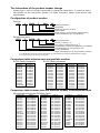
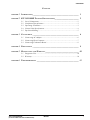
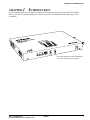
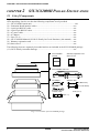
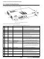
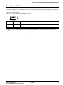
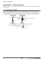
1
MF985-03
CMOS 4-BIT SINGLE CHIP MICROCOMPUTER
S5U1C62000H Manual
(S1C60/62 Family In-Circuit Emulator)
NOTICE
No part of this material may be reproduced or duplicated in any form or by any means without the written permission of Seiko
Epson. Seiko Epson reserves the right to make changes to this material without notice. Seiko Epson does not assume any
liability of any kind arising out of any inaccuracies contained in this material or due to its application or use in any product or
circuit and, further, there is no representation that this material is applicable to products requiring high level reliability, such
as medical products. Moreover, no license to any intellectual property rights is granted by implication or otherwise, and there
is no representation or warranty that anything made in accordance with this material will be free from any patent or copyright
infringement of a third party. This material or portions thereof may contain technology or the subject relating to strategic
products under the control of the Foreign Exchange and Foreign Trade Law of Japan and may require an export license from
the Ministry of International Trade and Industry or other approval from another government agency.
MS-DOS, Windows, Windows 95, Windows 98 and Windows NT are registered trademarks of Microsoft Corporation, U.S.A.
PC-DOS, PC/AT, PS/2, VGA, EGA and IBM are registered trademarks of International Business Machines Corporation, U.S.A.
NEC PC-9800 Series and NEC are registered trademarks of NEC Corporation.
All other product names mentioned herein are trademarks and/or registered trademarks of their respective owners.
© SEIKO EPSON CORPORATION 2001 All rights reserved.
The information of the product number change
Starting April 1, 2001, the product number will be changed as listed below. To order from April 1,
2001 please use the new product number. For further information, please contact Epson sales
representative.
Configuration of product number
Devices
S1
C
60N01
F
0A01
00
Packing specification
Specification
Package (D: die form; F: QFP)
Model number
Model name (C: microcomputer, digital products)
Product classification (S1: semiconductor)
Development tools
C
60R08
S5U1
D1
1
00
Packing specification
Version (1: Version 1 ∗2)
Tool type (D1: Development Tool ∗1)
Corresponding model number (60R08: for S1C60R08)
Tool classification (C: microcomputer use)
Product classification
(S5U1: development tool for semiconductor products)
∗1: For details about tool types, see the tables below. (In some manuals, tool types are represented by one digit.)
∗2: Actual versions are not written in the manuals.
Comparison table between new and previous number
S1C60 Family processors
Previous No.
E0C6001
E0C6002
E0C6003
E0C6004
E0C6005
E0C6006
E0C6007
E0C6008
E0C6009
E0C6011
E0C6013
E0C6014
E0C60R08
New No.
S1C60N01
S1C60N02
S1C60N03
S1C60N04
S1C60N05
S1C60N06
S1C60N07
S1C60N08
S1C60N09
S1C60N11
S1C60N13
S1C60140
S1C60R08
S1C62 Family processors
Previous No.
E0C621A
E0C6215
E0C621C
E0C6S27
E0C6S37
E0C623A
E0C623E
E0C6S32
E0C6233
E0C6235
E0C623B
E0C6244
E0C624A
E0C6S46
New No.
S1C621A0
S1C62150
S1C621C0
S1C6S2N7
S1C6S3N7
S1C6N3A0
S1C6N3E0
S1C6S3N2
S1C62N33
S1C62N35
S1C6N3B0
S1C62440
S1C624A0
S1C6S460
Previous No.
E0C6247
E0C6248
E0C6S48
E0C624C
E0C6251
E0C6256
E0C6292
E0C6262
E0C6266
E0C6274
E0C6281
E0C6282
E0C62M2
E0C62T3
New No.
S1C62470
S1C62480
S1C6S480
S1C624C0
S1C62N51
S1C62560
S1C62920
S1C62N62
S1C62660
S1C62740
S1C62N81
S1C62N82
S1C62M20
S1C62T30
Comparison table between new and previous number of development tools
Development tools for the S1C60/62 Family
Previous No.
ASM62
DEV6001
DEV6002
DEV6003
DEV6004
DEV6005
DEV6006
DEV6007
DEV6008
DEV6009
DEV6011
DEV60R08
DEV621A
DEV621C
DEV623B
DEV6244
DEV624A
DEV624C
DEV6248
DEV6247
New No.
S5U1C62000A
S5U1C60N01D
S5U1C60N02D
S5U1C60N03D
S5U1C60N04D
S5U1C60N05D
S5U1C60N06D
S5U1C60N07D
S5U1C60N08D
S5U1C60N09D
S5U1C60N11D
S5U1C60R08D
S5U1C621A0D
S5U1C621C0D
S5U1C623B0D
S5U1C62440D
S5U1C624A0D
S5U1C624C0D
S5U1C62480D
S5U1C62470D
Previous No.
DEV6262
DEV6266
DEV6274
DEV6292
DEV62M2
DEV6233
DEV6235
DEV6251
DEV6256
DEV6281
DEV6282
DEV6S27
DEV6S32
DEV6S37
EVA6008
EVA6011
EVA621AR
EVA621C
EVA6237
EVA623A
New No.
S5U1C62620D
S5U1C62660D
S5U1C62740D
S5U1C62920D
S5U1C62M20D
S5U1C62N33D
S5U1C62N35D
S5U1C62N51D
S5U1C62560D
S5U1C62N81D
S5U1C62N82D
S5U1C6S2N7D
S5U1C6S3N2D
S5U1C6S3N7D
S5U1C60N08E
S5U1C60N11E
S5U1C621A0E2
S5U1C621C0E
S5U1C62N37E
S5U1C623A0E
Previous No.
EVA623B
EVA623E
EVA6247
EVA6248
EVA6251R
EVA6256
EVA6262
EVA6266
EVA6274
EVA6281
EVA6282
EVA62M1
EVA62T3
EVA6S27
EVA6S32R
ICE62R
KIT6003
KIT6004
KIT6007
New No.
S5U1C623B0E
S5U1C623E0E
S5U1C62470E
S5U1C62480E
S5U1C62N51E1
S5U1C62N56E
S5U1C62620E
S5U1C62660E
S5U1C62740E
S5U1C62N81E
S5U1C62N82E
S5U1C62M10E
S5U1C62T30E
S5U1C6S2N7E
S5U1C6S3N2E2
S5U1C62000H
S5U1C60N03K
S5U1C60N04K
S5U1C60N07K
CONTENTS
CONTENTS
CHAPTER
1 INTRODUCTION ____________________________________________ 1
CHAPTER
2 S5U1C62000H PACKAGE SPECIFICATIONS _______________________ 2
2.1
2.2
2.3
2.4
2.5
CHAPTER
List of Components ....................................................................................... 2
Component Specifications ............................................................................ 3
Operating Conditions ................................................................................... 3
Control Unit Specifications .......................................................................... 4
Dip Switch Setting ......................................................................................... 5
3 CONNECTIONS ____________________________________________ 6
3.1
3.2
3.3
Connecting AC Adapter ................................................................................ 6
Connecting Host Computer .......................................................................... 7
Connecting Evaluation Board ...................................................................... 8
CHAPTER
4 PRECAUTIONS ____________________________________________ 9
CHAPTER
5 MAINTENANCE AND WARRANTY ________________________________ 10
5.1
5.2
CHAPTER
Diagnostic Test ............................................................................................. 10
Warranty ....................................................................................................... 10
6 TROUBLESHOOTING ________________________________________ 11
S5U1C62000H MANUAL
(S1C60/62 FAMILY IN-CIRCUIT EMULATOR)
EPSON
i
CHAPTER 1: INTRODUCTION
CHAPTER 1
INTRODUCTION
This manual describes how to operate, maintain and connect the in-circuit emulator S5U1C62000H.
Refer to the "S5U1C62000A Manual" for details of the S5U1C62000H functions and usage of the
commands.
3.2A
FUSE
∗ The name 'ICE62R' on the development
tool is the old name of the product.
S5U1C62000H MANUAL
(S1C60/62 FAMILY IN-CIRCUIT EMULATOR)
EPSON
1
CHAPTER 2: S5U1C62000H PACKAGE SPECIFICATIONS
CHAPTER 2
S5U1C62000H PACKAGE SPECIFICATIONS
2.1 List of Components
Figure 2.1.1 shows the contents of the S5U1C62000H package.
After unpacking, check to see that the following components are all provided.
(1) S5U1C62000H (main unit) ........................................................................................ one
(2) Evaluation Board interface cables .......................................................................... two
(3) 9-pin/9-pin RS232C cable ...................................................................................... one
(4) 9-pin/25-pin RS232C cable .................................................................................... one
(5) AC power cable ....................................................................................................... one
(6) AC adapter .............................................................................................................. one
(7) Fuse (3.2 A) ............................................................................................................ one
(8) S5U1C62000H Manual (S1C60/62 Family In-Circuit Emulator) (this manual) .. one
(9) Warranty registration card ...................................................................................... one
(10) Notes on use ........................................................................................................... one
The following items are separately forwarded and are not included in the S5U1C62000H package.
(11) S1C62 Family Assembler Package ........................................................................ one
•Warranty registration card
•Notes on use
•S5U1C62000H
Manual
EPSON
Registration
..............
..........
............
........
CMOS 4-bit Microcomputer S1C60/62 Family
S5U1C62000I Manual
SEIKO EPSON CORPORATION
•S5U1C62000H main unit
BREAK
FUSE 3.2A
RESET
GND HALT SYNC
•AC adapter
•RS232C cable
(for IBM PC/AT)
(for PC-98 Series)
•AC cable
•Evaluation Board
interface cable
•Fuse (3.2 A)
(50pin × 2)
Fig. 2.1.1 Contents of S5U1C62000H package
2
EPSON
S5U1C62000H MANUAL
(S1C60/62 FAMILY IN-CIRCUIT EMULATOR)
CHAPTER 2: S5U1C62000H PACKAGE SPECIFICATIONS
2.2 Component Specifications
Table 2.2.1 shows the specifications of the components included in the S5U1C62000H Package.
Table 2.2.1 Specifications of S5U1C62000H components
No.
Component
Item
1 S5U1C62000H
Dimensions
Weight
External color
Input voltage
Current consumption
Mounted board
2 Evaluation Board
Length
interface cable
Interface level
Cable
Cable-ended connector
Mating connector
3 9-pin/9-pin RS232C Length
cable
Interface level
Cable
Cable-ended connector
Connector on host side
4 9-pin/25-pin RS232C Length
cable
Interface level
Cable
Cable-ended connector
Connector on host side
5 AC adapter
Dimensions
Input voltage
Input frequency
Output voltage/current
6 AC power cable
Length
Plug type
7 Package
Dimensions
Materials
Total weight of package
8 Fuse
Type
Specification
275(L) × 195(W) × 40(H) mm
Approx. 1.7 kg (main unit only)
Cygnus white
5 V DC
2 A Max.
One ICE board
50 cm
CMOS interface (5 V)
50-pin flat cable
7950-6500SC (3M)
3433-6002LCSC (3M)
3m
EIA-RS232C level
12-pair shielded cabtyre cable
DEU-9S-F0
DEU-9P
3m
EIA-RS232C level
12-pair shielded cabtyre cable
DBU-25P-F0
DBU-25S
160(L) × 80(W) × 60(H) mm
90 to 264 V AC
47 to 63 Hz
5 V DC, 5 A
1.8 m
Bipolar with ground
380(L) × 260(W) × 190(H) mm
W carton, cardboard
Approx. 4.5 kg
DM32 (3.2 A)
Remarks
Rubber feet included
Same for both
Same for both
or equivalent
or equivalent
or equivalent
Overcurrent protection
function built-in
2.3 Operating Conditions
Table 2.3.1 shows operating conditions for the S5U1C62000H. The S5U1C62000H should be used under
the specified conditions.
Table 2.3.1 Operating conditions
No.
1
2
3
4
5
Item
Operating temperature
Storage temperature
Operating humidity
Storage humidity
Resistance to vibration
6 Resistance to impulse
Condition
5 to 40°C
-20 to 60°C
35 to 80%
20 to 90%
Operating:
Transportation:
Operating:
Standby:
S5U1C62000H MANUAL
(S1C60/62 FAMILY IN-CIRCUIT EMULATOR)
Remarks
No condensation
0.25G Max.
2G Max.
1G Max.
2G Max.
EPSON
3
CHAPTER 2: S5U1C62000H PACKAGE SPECIFICATIONS
2.4 Control Unit Specifications
This section describes the operation of the switches and other control units on the S5U1C62000H. Figure
2.4.1 shows the external view of the S5U1C62000H.
9
8
14
3.2A
FUSE
15
1
13
6
5
4
7
2
3
12
10 11
Fig. 2.4.1 S5U1C62000H external view
Table 2.4.1 lists the functions of the control units.
Table 2.4.1 Functions of S5U1C62000H control unit
No. Position
1 Front
Silk screen
Name
Function
This fuse protects power surge on the VDD line to be
supplied to the S1C62 Family Evaluation Board. It is
cutoff if 3.2 A or more current flows.
2 Front
RESET
Reset switch
Resets the S5U1C62000H.
3 Front
BREAK
Break switch
Forcibly breaks the program being executed.
4 Front
SYNC
Synchronous output terminal Used in the BSYN mode. This terminal outputs a
pulse at the break point.
5 Front
HALT
HALT signal output terminal This terminal goes to a low level when the Evaluation Board CPU enters the HALT status. Used to
measure CPU running effect.
6 Front
GND
Ground for oscilloscope
Connected to the GND clip of an oscilloscope.
7 Front
DSW
Dip switch
Used for setting the communication interface
between the host computer. The default baud rate has
been set to 9600 bps. See Section 2.5 for details.
8 Right side F1, F5
Evaluation Board
Used to connect the Evaluation Board interface
cable connectors
cables.
9 Top
LOW, HIGH ROM sockets
Target program ROMs are mounted. The LOW
socket is for the ROM that contains the low-order 8
bits (I7–I0) of the instructions and the HIGH socket
is for the ROM that contains the high-order 4 bits
(IB–I8).
10 Top
POWER
Power-on LED
Lit in red while the S5U1C62000H is on.
11 Top
EMULATION Emulation LED
Lit while the target program is running.
12 Top
HALT
HALT LED
Lit while the Evaluation Board CPU is in the HALT
status. (Also lights at power-on.)
13 Left side RS232C
RS232C cable connector
Used to connect the RS232C cable. The cable
connector should be attached with the screws.
14 Left side DC 5V
DC input connector
Used to connect the AC adapter.
15 Left side POWER SW Power switch
Turns the S5U1C62000H on and off. Pressing the switch
to I side turns the power on and O side turns the power off.
4
FUSE 3.2A
Fuse
EPSON
S5U1C62000H MANUAL
(S1C60/62 FAMILY IN-CIRCUIT EMULATOR)
CHAPTER 2: S5U1C62000H PACKAGE SPECIFICATIONS
2.5 Dip Switch Setting
The S5U1C62000H can be controlled by a host computer (NEC PC-98 Series, IBM PC/AT or its
compatible machine). To communicate between the S5U1C62000H and the host computer, it is necessary
to set the same baud rate and transfer data specifications in both. For the S5U1C62000H, the baud rate
can be set by a dip switch.
Figure 2.5.1 shows the settings with the dip switch.
OPEN
1
1
2
2
3
4
3
ON
4
ON OPEN OPEN OPEN
OPEN ON OPEN ON
ON
ON OPEN OPEN
Other settings
Setting
9600 bps, 8-bit character, 1 stop bit, no parity (factory setting)*1
4800 bps, 8-bit character, 1 stop bit, no parity
1200 bps, 8-bit character, 1 stop bit, no parity
Reserved for testing. (Do not set.)
∗1 Set the serial port of the host computer to 9,600 bps, 8-bit character, 1 stop bit and no parity as much as possible.
Fig. 2.5.1 Dip switch setting
S5U1C62000H MANUAL
(S1C60/62 FAMILY IN-CIRCUIT EMULATOR)
EPSON
5
CHAPTER 3: CONNECTIONS
CHAPTER 3
CONNECTIONS
This chapter describes connecting the S5U1C62000H with the host computer and the Evaluation Board
(S5U1C62xxxE).
3.1 Connecting AC Adapter
The S5U1C62000H package includes a dedicated AC adapter and an AC power cable (bipolar, with
ground). Connect the DC cable of the AC adapter to the DC IN terminal (5 V DC input terminal) of the
S5U1C62000H, and the AC power cable to the AC inlet of the AC adapter. The common ground frame
line should be used for connecting the S5U1C62000H and the host computer as shown in Figure 3.1.1.
Host computer
S5U1C62000H
DC IN (DC 5V)
terminal
AC adapter dedicated for S5U1C62000H
AC inlet
DC cable
AC cable
AC line
Frame ground line
Fig. 3.1.1 Connection of AC line
6
EPSON
S5U1C62000H MANUAL
(S1C60/62 FAMILY IN-CIRCUIT EMULATOR)
CHAPTER 3: CONNECTIONS
3.2 Connecting Host Computer
<Connection between S5U1C62000H and IBM-PC/AT>
Figure 3.2.1 shows the external view of the 9-pin/9-pin RS232C cable connector and Table 3.2.1 shows
the signal specifications.
5
2
1
A
9
6
Viewed from side A
9-pin/9-pin RS232C cable connector
Fig. 3.2.1 9-pin/9-pin RS232C cable connector
Table 3.2.1 Signal specifications
Pin No.
Signal name
3
2
7
8
5
TXD
RXD
RTS
CTS
SG
Signal meaning
Transmit data from HOST to ICE
Receive data from ICE to HOST
Request to send from HOST
Clear to send from ICE
Signal ground
Remarks
Normally used as ON
Normally used as ON
IBM-PC/AT or compatible machine can be connected with the 9-pin/9-pin RS232C cable.
The 9-pin/9-pin RS232C cable has a male-pin connector and a female pin connector.
Connect the male-pin connector to the S5U1C62000H and the female-pin connector to the host computer.
Tightening the connectors with the screws is strongly recommended after the connection.
<Connection between S5U1C62000H and NEC PC-98 Series>
Figure 3.2.2 shows the external view of the 9-pin/25-pin RS232C cable connector and Table 3.2.2 shows
the signal specifications.
1 2 3
13
A
14
25
Viewed from side A
9-pin/25-pin RS232C cable connector
Fig. 3.2.2 9-pin/25-pin RS232C cable connector
Table 3.2.2 Signal specifications
Pin No.
Signal name
2
3
4
5
7
TXD
RXD
RTS
CTS
SG
Signal meaning
Transmit data from HOST to ICE
Receive data from ICE to HOST
Request to send from HOST
Clear to send from ICE
Signal ground
Remarks
Normally used as ON
Normally used as ON
Use the 9-pin/25-pin RS232C cable for connecting the S5U1C62000H to the NEC PC-98 Series.
Tightening the connectors with the screws is strongly recommended after the connection.
S5U1C62000H MANUAL
(S1C60/62 FAMILY IN-CIRCUIT EMULATOR)
EPSON
7
CHAPTER 3: CONNECTIONS
3.3 Connecting Evaluation Board
Figure 3.3.1 shows the external view of the Evaluation Board interface cable.
2 1
2 1
50 49
50 49
S5U1C62000H side
Evaluation Board side
Fig. 3.3.1 External view of Evaluation Board interface cable
<Connection between S5U1C62000H and Evaluation Board>
The Evaluation Board interface cables are connected to the F1 and F5 connectors of the S5U1C62000H
with its projections (to prevent wrong insertion) inside (cable side). Likewise, they are connected to the
Evaluation Board with its projections outside.
The F1 and F5 connectors are lined up vertically on the side panel of the S5U1C62000H. Connect the F1
cable to the upper connector and the F5 cable to the lower connector.
Figure 3.3.2 shows the cable connection diagram.
S5U1C62000H
F1
Evaluation
Board
F5
←F1 connector
←F5 connector
Red mark
Fig. 3.3.2 Cable connection between S5U1C62000H and Evaluation Board
Note: The Evaluation Board has the VDD and VSS terminals used when operating by itself. Do
not connect to these terminals when connecting to the S5U1C62000H. Power for the
Evaluation Board is supplied from the S5U1C62000H through the F1 and F5 cables.
<Connection between S5U1C62000H and small-sized Evaluation Board>
The interface cables and connection to the F1 and F5 connectors of the S5U1C62000H are the same as
the Evaluation Board described above.
The F1 and F5 connectors of the small-sized Evaluation Board are lined up the same as the
S5U1C62000H. Connect the F1 cable to the upper connector and the F5 cable to the lower connector.
S5U1C62000H
Small-sized
Evaluation
Board
Red mark
←F1 connector
←F5 connector
F1 connector→
F5 connector→
Fig. 3.3.3 Cable connection between S5U1C62000H and small-sized Evaluation Board
Note: The small-sized Evaluation Board has the DC IN (5V DC input terminal), GND and 5 V
terminals used when operating by itself. Do not connect to these terminals when connecting to the S5U1C62000H. Power for the small-sized Evaluation Board is supplied from the
S5U1C62000H through the F1 and F5 cables.
8
EPSON
S5U1C62000H MANUAL
(S1C60/62 FAMILY IN-CIRCUIT EMULATOR)
CHAPTER 4: PRECAUTIONS
CHAPTER 4
PRECAUTIONS
To use S5U1C62000H properly, observe the following precautions:
• Turn off the S5U1C62000H and the host computer before connecting or removing the cables. Especially take care of the connection or removal of the Evaluation Board interface cable. Since the
interface is CMOS level, connection/removal when the S5U1C62000H is on may break internal
integrated circuits permanently.
• Do not turn the S5U1C62000H on again immediately after power-off. Wait for at least 10 seconds
before power-on; otherwise the LCA configuration of the Evaluation Board may be made improperly,
causing abnormal operation, or the fuse of the S5U1C62000H may be cut off.
• Leave the LOW and HIGH levers of the ROM sockets in a horizontal position. Leave these levers in
vertical position only when mounting or removing ROMs. Note that leaving them vertical for a long
period of time may cause an improper connection.
S5U1C62000H MANUAL
(S1C60/62 FAMILY IN-CIRCUIT EMULATOR)
EPSON
9
CHAPTER 5: MAINTENANCE AND WARRANTY
CHAPTER 5
MAINTENANCE AND WARRANTY
5.1 Diagnostic Test
The S5U1C62000H performs a self diagnostic test after power on.
The following messages show that the hardware has no problem.
<start-up message>
* ICE POWER ON RESET *
* DIAGNOSTIC TEST OK *
...(1)
#
When an error occurs in the self diagnostic test, an error message appears instead of the message (1)
below.
Examples of error messages:
* ROM CHECK ERROR 5=>FF *
* ROM CHECK ERROR 001111 55=> *
In these cases, the S5U1C62000H hardware has problems. Do not try to use further.
5.2 Warranty
Refer to the attached warranty card.
10
EPSON
S5U1C62000H MANUAL
(S1C60/62 FAMILY IN-CIRCUIT EMULATOR)
CHAPTER 6: TROUBLESHOOTING
CHAPTER 6
TROUBLESHOOTING
This chapter summarizes possible errors related with system operation, along with possible solutions for
them.
• Debugger cannot be loaded.
Be sure that the host computer has a satisfactory memory capacity.
(See "S5U1C62000A Manual".)
Be sure that the software is loaded in a proper operating system.
(See "S5U1C62000A Manual".)
• Debugger can be loaded, without prompt for command entry.
Be sure that the RS232C cable is connected properly.
Be sure that the S5U1C62000H dip switch is set properly.
• Communication error is displayed with a prompt for command entry.
Be sure that the baud rate of the host computer is the same as the S5U1C62000H.
Be sure that the S5U1C62000H is turned on.
• The fuse (FUSE 3.2A) cuts off when S5U1C62000H is turned on.
Be sure that the F1 and F5 connectors are hooked up properly.
Be sure that the power input terminals (VDD, VSS, etc.) of the Evaluation Board are open.
Be sure that there is no problem in the user I/O section connected to the Evaluation Board.
Before replacing the fuse with a spare, make sure the above conditions are met. The fuse can be
removed from its holder by pulling it towards the front.
• After the S5U1C62000H system has been loaded, the message * TARGET DOWN * is displayed
with a prompt for command entry.
Be sure that the F1 and F5 connectors are connected properly.
Be sure that the fuse (FUSE 3.2A) is not cut.
For errors which may occur with other commands, see "S5U1C62000A Manual" for proper key operations.
S5U1C62000H MANUAL
(S1C60/62 FAMILY IN-CIRCUIT EMULATOR)
EPSON
11
International Sales Operations
AMERICA
ASIA
EPSON ELECTRONICS AMERICA, INC.
EPSON (CHINA) CO., LTD.
- HEADQUARTERS -
28F, Beijing Silver Tower 2# North RD DongSanHuan
ChaoYang District, Beijing, CHINA
Phone: 64106655
Fax: 64107319
1960 E. Grand Avenue
EI Segundo, CA 90245, U.S.A.
Phone: +1-310-955-5300
Fax: +1-310-955-5400
SHANGHAI BRANCH
4F, Bldg., 27, No. 69, Gui Jing Road
Caohejing, Shanghai, CHINA
Phone: 21-6485-5552
Fax: 21-6485-0775
- SALES OFFICES West
150 River Oaks Parkway
San Jose, CA 95134, U.S.A.
Phone: +1-408-922-0200
Fax: +1-408-922-0238
Central
101 Virginia Street, Suite 290
Crystal Lake, IL 60014, U.S.A.
Phone: +1-815-455-7630
Fax: +1-815-455-7633
Northeast
301 Edgewater Place, Suite 120
Wakefield, MA 01880, U.S.A.
Phone: +1-781-246-3600
Fax: +1-781-246-5443
EPSON HONG KONG LTD.
20/F., Harbour Centre, 25 Harbour Road
Wanchai, Hong Kong
Phone: +852-2585-4600 Fax: +852-2827-4346
Telex: 65542 EPSCO HX
EPSON TAIWAN TECHNOLOGY & TRADING LTD.
10F, No. 287, Nanking East Road, Sec. 3
Taipei
Phone: 02-2717-7360
Fax: 02-2712-9164
Telex: 24444 EPSONTB
HSINCHU OFFICE
Southeast
3010 Royal Blvd. South, Suite 170
Alpharetta, GA 30005, U.S.A.
Phone: +1-877-EEA-0020 Fax: +1-770-777-2637
13F-3, No. 295, Kuang-Fu Road, Sec. 2
HsinChu 300
Phone: 03-573-9900
Fax: 03-573-9169
EPSON SINGAPORE PTE., LTD.
No. 1 Temasek Avenue, #36-00
Millenia Tower, SINGAPORE 039192
Phone: +65-337-7911
Fax: +65-334-2716
EUROPE
EPSON EUROPE ELECTRONICS GmbH
SEIKO EPSON CORPORATION KOREA OFFICE
- HEADQUARTERS Riesstrasse 15
80992 Munich, GERMANY
Phone: +49-(0)89-14005-0
Fax: +49-(0)89-14005-110
SALES OFFICE
Altstadtstrasse 176
51379 Leverkusen, GERMANY
Phone: +49-(0)2171-5045-0
Fax: +49-(0)2171-5045-10
UK BRANCH OFFICE
Unit 2.4, Doncastle House, Doncastle Road
Bracknell, Berkshire RG12 8PE, ENGLAND
Phone: +44-(0)1344-381700
Fax: +44-(0)1344-381701
50F, KLI 63 Bldg., 60 Yoido-dong
Youngdeungpo-Ku, Seoul, 150-763, KOREA
Phone: 02-784-6027
Fax: 02-767-3677
SEIKO EPSON CORPORATION
ELECTRONIC DEVICES MARKETING DIVISION
Electronic Device Marketing Department
IC Marketing & Engineering Group
421-8, Hino, Hino-shi, Tokyo 191-8501, JAPAN
Phone: +81-(0)42-587-5816
Fax: +81-(0)42-587-5624
ED International Marketing Department Europe & U.S.A.
FRENCH BRANCH OFFICE
1 Avenue de l' Atlantique, LP 915 Les Conquerants
Z.A. de Courtaboeuf 2, F-91976 Les Ulis Cedex, FRANCE
Phone: +33-(0)1-64862350
Fax: +33-(0)1-64862355
BARCELONA BRANCH OFFICE
Barcelona Design Center
Edificio Prima Sant Cugat
Avda. Alcalde Barrils num. 64-68
E-08190 Sant Cugat del Vallès, SPAIN
Phone: +34-93-544-2490
Fax: +34-93-544-2491
421-8, Hino, Hino-shi, Tokyo 191-8501, JAPAN
Phone: +81-(0)42-587-5812
Fax: +81-(0)42-587-5564
ED International Marketing Department Asia
421-8, Hino, Hino-shi, Tokyo 191-8501, JAPAN
Phone: +81-(0)42-587-5814
Fax: +81-(0)42-587-5110
S5U1C62000H Manual
(S1C60/62 Family In-Circuit Emulator)
ELECTRONIC DEVICES MARKETING DIVISION
EPSON Electronic Devices Website
http://www.epson.co.jp/device/
First issue June, 1997
Printed March, 2001 in Japan M A