1
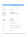
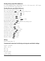
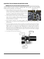
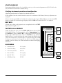
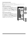
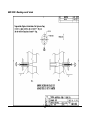
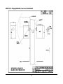
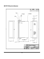
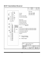
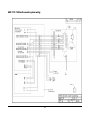
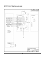
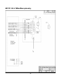
E N V I R O N M E N T A L M O N I T O R S E R V I C E , I N C . 09/1 5/2011 REV-1 6 Model 1304 Installation and Operation Manual Environmental Monitor Service, Inc. • PO BOX 4340 Yalesville, CT 06492 Phone 203.935.0102 • Fax 203.634.6663 Sales@emsct.com Prepared by: James F. Cognetta 0 Ship to: ENVIRONMENTAL MONITOR SERVICE 87 Gypsy Lane Meriden, CT. 06450 Phone 203.935.0102 ext 14 Fax 203.634.6663 E-mail: service@emsct.com Warnings and Safety Guidelines Guidelines for user safety and equipment protection This manual is intended to aid trained and competent personnel in the installation of this equipment. Only a technician or engineer trained in the local and national electrical standards should perform tasks associated with the electrical wiring of this device. Warnings Under no circumstances will Environmental Monitor Service, Inc. be liable or responsible for any consequential damage that may arise as a result of installation or use of this equipment. All examples and diagrams shown in the manual are intended to aid understanding. They do not guarantee operation. Environmental Monitor Service, Inc. accepts no responsibility for actual use of this product based on these examples. Due to the great variety of possible applications for this equipment, the user must assess the suitability of this product for specific applications. Make sure to have safety procedures in place to stop any connect3ed equipment in a safe manner if the controller should malfunction or become damaged for any reason. Do not replace electrical parts or try to repair this product in any way. Only qualified factory trained service personnel trained in is operation should open the device’s housing or carry out repairs. The manufacturer is not responsible for problems resulting from improper or irresponsible use of this device. You may cause an electric shock, fire or damage the equipment if you ignore any of these safety precautions. 1 1. Limited Warranty a) Warranty. i) Except as otherwise provided herein, Seller warrants to Buyer that the Products sold to Buyer are, at the time of shipment to Buyer from Seller, free from defects in material and workmanship. ii) This warranty shall be valid for a period of twelve (12) months from the date of shipment to Buyer, unless a different period is specified herein, or in Seller’s applicable price list in which case the specified period shall apply. Notwithstanding anything to the contrary contained herein, the warranty period for spare parts, data processing equipment, including data storage devices, processors, printers, terminals, communication interfaces, tape drives and all similar devices, and is in all cases limited to ninety (90) days from the date of shipment to Buyer. iii) Except in the case of an authorized distributor of Seller, authorized in writing by Seller to extend this warranty to the distributor’s customers, the warranty herein applies only to Buyer as the original purchaser from Seller and may not be assigned, sold or otherwise transferred to any third party. iv) As Buyer's sole and exclusive remedy under this warranty, Seller agrees either to repair or replace, at Seller's sole option, any part or parts of such Products which, under proper and normal conditions of use, prove(s) to be defective within the applicable warranty period. Alternately, Seller may at any time, in its sole discretion, elect to discharge its warranty obligation hereunder by accepting the return of any defective Product pursuant to the terms set forth herein and refunding the purchase price paid by Buyer. b) Exclusions and Limitations. i) It is recognized that some parts by their nature may not function for the warranty period applicable to the Product. Therefore, excluded from the warranty herein are ceramic material cells and/or holders, and other similar parts referenced in the applicable operating manual. ii) The warranty herein excludes any equipment or accessories which are identified on applicable price lists, quotations, special promotional materials, or on the face hereof, for which this limited warranty may be further limited. Included within this category are items produced by third party manufacturers (as to which Seller passes to Buyer the warranty it has been provided by the manufacturer) and items which are sold at specially reduced prices with reduced warranty protection (in some cases, extended warranty protection may be available at an increased price). iii) This warranty does not cover loss, damage, or defects resulting from: transportation to the Buyer's facility, improper or inadequate maintenance by Buyer, Buyer-supplied software or interfacing, unauthorized modification or misuse, operation outside of the environmental specifications for the Product or improper site preparation or maintenance. iv) No warranty is made with respect to used, reconstructed, refurbished or previously owned Products, which will be so marked on the face hereof and, unless otherwise indicated on the face hereof, shall be sold “As Is”. v) The warranty herein applies only to Products within the country of original delivery. Products transferred outside the country of original delivery, either by Seller at the direction of Buyer or by Buyer’s actions subsequent to delivery, may be subject to additional charges prior to warranty repair or replacement of such Products based on the actual location of such Products and Seller’s warranty and/or service surcharges for such location(s). c) Place of Service. Except when otherwise provided in Seller's current applicable price list, Seller shall perform all warranty services hereunder at the Seller’s facility, as soon as reasonably practicable after notification by the Buyer of a possible defect. Seller requires that the Buyer request from the Seller a Return Authorization Number prior to returning the Product to Seller's production facility, transportation charges prepaid, when necessary to provide proper warranty service. d) In the case of onsite warranty. The Seller reserves the right to charge for travel time and all travel expenses to and from the Seller’s site and Buyers facility. The actual onsite labor time to install, test replace, adjust etc., to complete the warranty work onsite shall NOT be charged to the Buyer. 2 e) Software and Firmware Products. The sole and exclusive warranty applicable to software and firmware products provided by Seller for use with a processor will be as follows: Seller warrants that such software and firmware will conform to Seller's program manuals current at the time of shipment to Buyer when properly installed on that processor, provided however that Seller does not warrant that the operation of the processor or software or firmware will be uninterrupted or error-free. NO OTHER WARRANTY IS EXPRESSED OR IMPLIED. SELLER EXPRESSLY DISCLAIMS THE IMPLIED WARRANTIES OF MERCHANTABILITY AND FITNESS FOR A PARTICULAR PURPOSE. 3 Mounting the air plenum and weather covers 18 Transceiver and retro reflector assembly19 Air flow switch 21 Control unit 21 Section 3 22 Before start up 22 Stack exit correlation computation22 Start up service 23 Verifying instrument operation and configuration 23 EDIT Keys 23 Factory O.P.L.R. Display 23 Quick Menu 23 Zero/Span calibration Check 24 Section 4 25 Instrument operations and adjustments 25 Overview of the systems operation 25 Front Panel LED's 25 Fault Messages 25 Control unit manual controls 26 Alarm set point adjustments 26 Alarm Time Delay Adjustment 26 4-20mA outputs 27 Recorder or other device calibration: 27 Auto cal timer Adjustment 28 Disable internal cal timer 28 Remote calibration cycle initiate 28 Remote calibration cycle acknowledgment28 Section 5 30 Ajustments 30 Clear on stack zero and span calibration30 Zero reflector adjustment 30 Span filter VALUE 31 Record the zero/span values in the quick menu 31 Off stack zero calibration 32 Section 6 33 using the on line zero reflector (option) 33 Procedure 33 Table of Contents Guidelines for user safety and equipment protection 1 Warnings 1 Warrantee Registration 6 Customer service 7 Claims for damaged shipments 8 Shipping discrepancies 8 Section 1 9 System Description 9 Transmissometer/retro reflector 9 Control Unit 9 Optional Air Purge Weather Cover System 9 Alignment system 9 Cabling 9 Principle of Operation 10 Normal mode of operation 10 Internal calibration system, zero mode 10 Internal calibration system, Span mode10 1304 Opacity Specifications 12 Section 2 14 Installation Considerations 14 Choose an installation site 14 Accessibility 14 Environment 14 Stack exit 14 Installation – Mechanical 14 Drawing notes 14 Sensors height from Platforms, walk way/ decks, etc, 14 Alignment of stack flanges 15 Installation procedure - stack flanges 15 Sample area 15 Modbus Communication and Addresses 15 Reading Analog output Block Addresses:16 Reading Discrete output Block Addresses: 16 Writing: 16 Communication menu has the following sub categories and default settings: 16 Changing communication settings: 17 Mounting the air plenum and weather covers 17 4 Filter correction 33 Course adjustments 35 Micro-turn parts list 35 Filter certification 36 Section 7 37 Preventive/corrective maintenance37 Preventive/corrective maintenance schedule 37 Trouble Shooting 40 Trouble shooting -continued 41 Spare parts 42 Section 8 44 Drawings 44 EMS 1001 - Mounting under 6‘ STACK 45 EMS 1002 - Mounting over 6’ stack 46 EMS 1024 - Air purge/Weather cover mech Installation 47 EMS 1078 - PANEL cut out for 1304 control unit 48 EMS 1079 -1304 control unit dimensions 49 EMS 1077 - Terminal identification 1304 control unit 50 EMS 1131 -1304 with recorder system wiring 51 Purge blower electrical and pressure information 52 EMS1101 - Sht 1 of 3 Dual Blower system wiring 53 EMS 1101 - Sht 2 of 3 Single Blower system wiring 54 EMS 1101 - Sht 3 of 3 Without Blower system wiring 55 5 WARRANTEE REGISTRATION Read this manual before attempting installation! Information contained in this manual is subject to change without notice and does not represent a commitment on the part of Environmental Monitor Service, Inc. Environmental Monitor Service, Inc. reserves the right to make changes in the construction, design, specifications, and/or procedures that may not be reflected in this manual. This manual is furnished on the express condition that the information herein will not be used for second source procurement, directly or indirectly detrimental to the interest of Environmental Monitor Service, Inc. NOTICE: To register your warrantee and to insure that you receive full coverage for your instrument, please complete and return this registration within two weeks of receipt of instrument. Please type or print. Company Name ___________________________________________________________________ Division __________________________________________________________________________ Mailing Address ___________________________________________________________________ City, State Postal Code, Country _______________________________________________________ Telephone & Fax ___________________________________________________________________ Instrument Model. ____________________________________________________________ Serial Number __________________________________________________________________ Maintenance person Name __________________________________________________________ Department Name __________________________________________ Phone __________________ Complete mailing address (if different from above) ________________________________________ What is the industry application for instrument? (i.e. chemical, recovery boiler, cement kiln etc.): ____ ________________________________________________________________________________ How will this instrument be used? ____Process Control ___ Combustion control ___ EPA Compliance Mail to: ENVIRONMENTAL MONITOR SERVICE Attn: Warrantee Registration PO Box 4340 Yalesville, CT. 06492 U.S.A. 6 Customer service We strive to provide efficient and expedient service when an instrument or component is returned for repair. Your assistance can help us to better provide the service you need. To assure that we process your factory repairs and returned goods efficiently and expeditiously, we need your help. Before you ship any equipment to our factory please call our Service Response Center at 1-800-864-2814. This enables us to complete the necessary paperwork and process your equipment correctly when it reaches our dock. When you call please be prepared to provide the following information: Your name and telephone number. Your company name with shipping address. The number of items being returned. The part number of each item. The model number or a description of each item. The serial number of each item, if applicable. A description of the problem you are experiencing if factory repair is needed, or the reason you are returning the equipment (e.g., sales return, warranty return, etc.). When you call in, our Customer Service Representative will assign an RMA (Return Material Authorization) number to your shipment and initiate the necessary paperwork to process your equipment as soon as it reaches us. Please include this RMA number with the equipment you return, preferably both inside and outside the shipping container. This will assure that your equipment receives the fastest attention possible. Your assistance in this matter will enable us to serve you better. We appreciate your cooperation and support of our products and services. 7 CLAIMS FOR DAMAGED SHIPMENTS Inspect all instruments thoroughly on receipt. Check material in the container (s) against the enclosed packing list. If the contents are damaged and/or the instrument fails to operate properly, notify the carrier and Environmental Monitor Service immediately. The following documents are necessary to support claims: Original freight bill and bill of lading Original invoice or photocopy of original invoice Copy of packing list Photographs of damaged equipment and container You may want tot keep a copy of these documents for your records also. Refer to the instrument name/model number, serial number, sales order number, and your purchase order number on all claims. Upon receipt of a claim, we will advise you of the disposition of your equipment for repair or replacement. SHIPPING DISCREPANCIES Check all containers against the packing list immediately on receipt. If a shortage or other discrepancy is found, notify the carrier and Environmental Monitor Service immediately. WE will not be responsible for shortages against the packing list unless they are reported promptly. 8 Section 1 SYSTEM DESCRIPTION The Model 1304 Opacity Monitor provides continuous, low maintenance, precision measurement of opacity and optical density in industrial applications. It is a cost-effective instrument that serves as an aid in operating pollution and/or process control equipment. Transmissometer/retro reflector The Model 1304 is a precision, double-pass, dual beam Transmissometer that consists of a transceiver (transmitter/receiver) mounted on one side of a stack or duct and a passive reflector mounted on the opposite side. The light source, photo detectors, and all measurement/reference optics used in opacity measurement are housed in the transceiver. The function of the reflector is to return the measurement beam to the detector in the transceiver, creating a double pass across the process stream. The standard reflector is used for measurement path lengths up to 15 feet. For longer path lengths, maximum 50 feet, reflectors, optical parts and electronics will vary. Control Unit The control unit should be mounted in a control room environment i.e., clean, temperature with max/min of +0o to +50 o C (+32 o to + 122 o F). The Model 1304 control unit provides instrument control functions, opacity readings, alarm and fault indicators, analog outputs, and diagnostics with contact closures. Optional Air Purge Weather Cover System The transceiver and reflector may be mounted in weather covers. The weather covers are fairly compact to allow movement around them even on a three-foot walkway or platform. They protect the stack-mounted components from dirt, moisture; stack temperatures within the specified ambient temperatures limits, and errant air currents around the stack. The air purge system constantly circulates air past the optical window. The air flow is directed through the hose to an air plenum on the stack side of the optical window. The air flow in the air plenum area results in reduced pressure and increased velocity. This venturi effect tends to continually draw the air around the optical window into the purge air stream, thereby keeping the lens clean for long periods. Alignment system The Model 1304 includes a built-in through-the-lens alignment system. The alignment target can be viewed through a window on the transceiver. Adjustments to changes in alignment are provided by a 3-point alignment system, which is integral to the air plenum. Cabling The standard cabling used between the stack-mounted units and the control unit is at a minimum 6-pair, #20 AWG, twisted, shielded cable separation distance approximately 2000FT.. More pairs or larger than 20 AWG is acceptable for longer distances. 9 PRINCIPLE OF OPERATION Normal mode of operation The Dual beam measurement system has a stack mounted Transmissometer sensor system consists of an optical transceiver mounted on one side of the stack and a retro reflector mounted on the other. To avoid errors due to ambient light, the lamp (See Drawing) is electronically modulated and projects a collimated beam of light, which is split into a reference beam, and a measurement beam by an optical Beam splitter. The reference beam is directed to the reference detector, RD. The measurement beam is projected across the stack to a Retro reflector that returns the beam back across the stack to a beam splitter and directs the measurement beam to the measurement detector, MD. A portion of the returning light is also sent to the TTL (Thru the Lens) bulls-eye target viewed through a window provided at the rear of the Transmissometer. The bulls-eye is used to correct changes in alignment and is unique in that no moving parts are used! The ratio of the measurement and reference detectors is used to provide Transmittance 2 (T 2) signal. Because the same light source is used for both detectors, and a Measurement / Reference ratio is used throughout for the calculations, the monitor is insensitive to variations in light intensity. Since all measurements are made on a ratio basis, all resulting computations are independent of the absolute intensity of the light source or contamination of the optics associated with the collection and focusing of the energy from the lamp. The (T 2) signal is converted to a current format and sent to the control unit for processing. At the control unit the signal is processed to read 0100% Opacity, provide alarms and outputs. Internal calibration system, zero mode Zero and span calibration checks can be initiated manually, automatically or by a PLC or computer. During the zero calibration mode a calibrated zero reflector is placed in front of the transceiver optical package testing all optical surfaces and electronic components to assure zero point has not changed. Internal calibration system, Span mode In the span mode a Span filter of known Neutral Density is placed in the measurement path and produces a specific up scale reading in accordance with the latest E.P.A. requirements. The zero and span cycle provides a continuous check of all the optical components and surfaces, the main lamp, the detector, interconnecting wiring, control unit and computation analysis. 10 TTL Bulls-eye Projection Lens Retro Reflector Aperture P Span Filter Main Lamp RD MD Aperture V Span Filter out: Span Filter in: Zero Reflector out: Zero Reflector in: 11 Zero Reflector 1304 OPACITY SPECIFICATIONS Design and performance: Meets or Exceeds PS-1 Revised and ASTM D6216-03 Peak and Mean Spectral Response Photopic; 515 to 585 nm, less than 10% of peak response outside 400 to 700 nm Relative spectral response <10% Angle of View < 4.0 o from optical axis Angle of Projection < 4.0 o from optical axis Calibration Error/accuracy +/- 1% of full scale Response time < 10 second Zero Drift < 0.5% Calibration Drift < 0.5% Operational Period In excess of PS-1 required 336 Hrs. Zero/Span Calibration Manual or automatic with zero mirror and neutral density filter Remote control unit: 120Vac +/- 10% 50/60hz 22va Numeric Digital Display 5/8 inch (15.9 mm), 4digit LED Display resolution Selectable for Instantaneous opacity, Average Opacity. Optional mg/m 3 0.1% Opacity Alphanumeric 8 character LED (0.2") Fault Display Air purge low, No Stack Power, T2 4-20 Lost/low, Maintenance Mode, Window Dust, Zero Cal Fail, Span Cal Fail, Manual Cal. Bargraph Operator Indicating LED’s Left/Right: 51 segments LED (5.1") for instant/average opacity. 20 segment LED (2.1") for window dust and drift in %opacity Run, Alarm, Operate, Cal in progress High Opacity Set Point 0-100% of full scale High Opacity Delay Adjustable 0-300 Seconds Hi Opacity Alarm Reset Automatic Open Transistor Collector Outputs Four selectable Dry Contacts Two selectable (option: two additional) Instantaneous Opacity and Average Outputs 4-20 mA grounded reference, 800 ohms max. (two additional optional) OPLR (Exit Correlation Lx / 2*Lt) 0.2 to 3.0 Cal cycle initiate Local, remote and timed Adjustable 1 to 24 hours Enclosure NEMA 13, IP65, Height: 7.38" x Wide: 3.00: x Depth: 7.75", Weight: 6 lbs. Ambient Temperature Range +0o to +50 o C ( +32 o to + 122 o F) Power Requirements 120 VAC (+/- 15%), 50/60 Hz, 22VA Network Protocol: Modbus (ASCII or RTU mode), type RS-485, optically isolated. Configuration Speed: 300-38,400 baud, type RS-232 Transceiver Service module: 120/220Vac +/- 10% 50/60hz, Transceiver 65va, Service Module 60va Display Local zero/span 5/8 inch (15.9 mm), 4-digit LED, selectable for % Opacity and % Transmittance Manual on demand Test jacks Transceiver to remote control current loop Diagnostics Loss of power, Current loop open, maintenance mode. Transceiver/ Reflector: 12 Enclosure NEMA 4 watertight enclosure Path Length 2 to 15 feet, 0.6 to 4.6 meters. Longer available Optical System Double Pass Light Source Aging Compensation Automatic Light Source Life > 5 years Ambient Temperature Limits -4 o to +131 o F (-20 o to +55 o C) Process Gas Alignment Verification Up to 750 o F (400 o C), standard (higher available-contact factory) Passive Built-in through-the-lens system Mounting Flanges 3 inch IPS, 150# pipe flange Ambient Light Immunity Solid-state electronic light modulation 13 Section 2 INSTALLATION CONSIDERATIONS Choose an installation site The primary considerations for choosing a site for the Model 1304 are accessibility, ambient environmental conditions, and locating the unit to obtain a representative sample of the process. Review the excerpt from the Federal Register in appendix for suggestions before selecting an installation site. The following general guidelines should also be considered. Accessibility Locate the instrument that provides safe access for periodic maintenance and inspection. A platform or walkway is required for access to the sensors and weather covers. Environment Locate the stack-mounted units in an area with ambient temperatures between -4 o to +130o F. (Consult the factory for other temperature ranges.) Areas that are clean and dry are desirable. Avoid areas with condensation. Maintenance intervals are directly related to the installation environment. Intervals can vary from 2 to 3 months in fairly clean environments, to twice a month in dirty environments. Lens cleaning is a function of the ambient conditions and cleanliness of the purge air. Locate the instrument to avoid excessive vibration or shock. Locate the control unit in an easily accessible area with temperatures between +32o to 122o F. To permit the operator to read and/or change controls, the unit should not be mounted higher than five feet from floor level. Stack exit Locate the transceiver more than two stack diameters down from the stack exit is recommended. INSTALLATION – MECHANICAL Drawing notes A review of the drawings and procedures provided will help to produce an error free installation. However, there are important additional points that must be observed. The beam of the instrument must be kept in the horizontal plane; the transceiver cannot be rotated more than +/- 10 o from vertical. The weather covers must be installed vertically plumb. Installation and wiring diagrams are found at the end of this manual. Please review all drawings prior to starting installation or wiring. If you have any questions please contact our service department for assistance at 203-9350102 ext. 14 Sensors height from Platforms, walk way/ decks, etc, A platform or walkway must be available for access to the weather covers. The optimum condition would have the mounting flanges and weather covers approximately 5 feet up from the floor, but in all cases, a minimum of 12 inches from the bottom of the weather cover to the floor is required to remove the air filters. Railings and other obstructions should allow the weather cover to swing clear as shown in the installation drawings. 14 Alignment of stack flanges Stack flange alignment is shown on Drawing EMS-1001 and EMS 1002, and is the first step in successful installation. The final beam alignment adjustments are described in the Beam Alignment Procedure. Installation procedure - stack flanges For an opacity monitor, the customer is required to supply and install two 3" I.P.S. flanges at eye level directly across from each other. The flange faces, mounted on pipe stubs, should be approximately 6" to 8" from the stack or insulation. On completion of the installation, the flanges must be aligned so that the total deviation of the light source flange relative to a common centerline, does not exceed +1o and the retro reflector flange does not exceed +3o . Flanges should be mounted approximately 5 feet up from the deck of platforms, roof or walk way. At installations where conditions permit, this may be accomplished by using a piece of 2 1/2" pipe suspended across the stack protruding far enough to allow slipping the 3" flange pipe assemblies over each end and welding in place as shown in Drawing section 8. Any deviation up to the previously specified limits can be adjusted out during the installation and alignment of the light source and retro reflector with the system's alignment adjustments. Where installations do not permit the use of the aforementioned method, the following procedure will accomplish the same results. (See drawing section 8.) An alignment tool can be purchased from the factory to insure accurate alignment. Accurately locate one 3 1/2" diameter hole (large enough to accept the 3" pipe) and the other hole approximately 1/2" diameter, directly across from each other. Attach the alignment tool to the flange/pipe assembly and insert the pipe into the 3 1/2" hole in the stack wall. Align the assembly with the 1/2" diameter hole on the opposite side by viewing through the alignment tool and weld the pipe in place. Care must be exercised when welding to maintain alignment. The 1/2" diameter hole should now be enlarged approximately 3 1/2" to accept the other flange/pipe assembly. Proceed in the same manner, installing the assembly with the alignment tool attached, and weld in place maintaining concentric alignment with the 3" pipe previously installed on the opposite wall. Sample area To achieve a representative sample, the accepted practice is to have the measurement path of the instrument directly in the centroidal area of the stack. An area should be chosen where the gases are not stratified in the stack or duct. (See Federal Register excerpt in section 7) Where a bend is involved, the path should be chosen to be the plane of the bend. Locations where large amounts of condensed water may be present should be avoided. MODBUS COMMUNICATION AND ADDRESSES Protocol: Modbus (ASCII or RTU mode) Speed: 1200-38,400 baud Type: RS-485, optically isolated RS-485 Modbus connections are 1-3 on the rear panel of the controller. RS-485 cabling may be up to 4000 feet in length. Belden P/N 3106A cable is recommended. 15 Reading Analog output Block Addresses: 0% to 100% instantaneous opacity = 40150 (integer) (xx.xx), 0% to 100% average opacity = 40151 (integer) (xx.xx), 0 to 10% Window Dust = 40073 (integer) (x.xx) Reading Discrete output Block Addresses: Relay 1- Cal in progress, duration 6 minutes (0 = cal, 1 = cal) Relay 2- High opacity alarm (0= Alarm, 1= Alarm) Note: always 0 during cal cycle. Cal. Zero Check, duration 3 minutes = 00066 (0 = cal, 1 = cal) Cal. Span Check, duration 3 minutes = 00065 (0 = cal, 1 = cal) Cal. Zero Fail Alarm = 00140 (0 = Alarm, 1 = Alarm) Cal. Span Fail Alarm = 00141 (0 = Alarm, 1 = Alarm) Lost Of 120VAC Transceiver Power = 00042 (0 = Alarm, 1 = Alarm) Dust/Zero Shift Alarm = 00075 (0 = Alarm, 1 = Alarm) High Opacity Alarm = 00097 (0 = Alarm, 1 = Alarm) Note: always 0 during cal cycle. Common Fault = 00098 (0 = Alarm, 1 = Alarm) Common fault individual blocks: Air purge Low = 00043 (0 = Alarm, 1 = Alarm) No Stack Power = 00042 (0 = Alarm, 1 = Alarm) T2 4-20mA Lost/Low = 00121 (0 = Alarm, 1 = Alarm) Maintenance Mode = 00041 (0 = Alarm, 1 = Alarm) Window Dust = 00075 (0 = Alarm, 1 = Alarm) Zero Cal Fail = 00140 (0 = Alarm, 1 = Alarm) Span Cal Fail = 00141 (0 = Alarm, 1 = Alarm) Manual Cal = 00048 (0 = Alarm, 1 = Alarm) Writing: Remote Cal. Initiate (Write) = 45 Communication menu has the following sub categories and default settings: Com port – 1 (automatic) Address – 1 (max 32) Baud – 38.4 Parity - Odd RTU/ASCII - ASCII +/- Data - Unsigned Time out – 30 seconds 16 Changing communication settings: Press EDIT (ESC) button, Scroll down EDIT to COM MENU, press ENTER, at COM PORT press ENTER set to 1 for Modbus then press EDIT (ESC) button it will return to COM Port. (Note: controllers will automatically choose Modbus when the RS 232 port is not in use.) Press the EDIT to go to Address press ENTER and use the EDIT down or up arrow to go to the address number assigned to this controller (default is 1), press EDIT (ESC) to return to Address. Continue as above until all settings are as desired. +19999 MESSAGE ACK “Edit Value” Light “Scroll Menu” light DIS Moves Message Cursor AUTO MAN REM LOC PV EDIT SP EDIT Keys OUT EDIT (ESC) ENTER EDIT Hinged Cover 17 MOUNTING THE AIR PLENUM AND WEATHER COVERS WARNING! Control unit, Transceiver & Retro serial numbers must match. After the installation site has been selected and the platform requirements have been met, the mounting flanges should be installed and aligned as described on Drawings EMS - 1001 and EMS - 1002. Flanges should be installed with the mounting faces on the vertical plane. Hinge Pin 1. Before installing the Transceiver, Retro reflector or any type of weather cover remove the air plenum from both the Transceiver and retro reflector. Removal will make the installation easier and less chance of damage while mechanical attachment of the air plenums and optional weather covers when provided. 2. If the transceiver and retro reflector have been shipped from the factory with the air plenum attached, un-clip both hold down latches, swing open and lift up & off the hinge pins. Place the Transceiver and retro in a safe place. 3. The air plenum is attached to the customer supplied 3" pipe flange by four 2 1/2" long 5/8-11 bolts. Working from the 3" flange the correct assembly is; gasket then air plenum. 4. If you have weather covers remove the two (2)-weather cover hood hinge pins located on the upper right and left hand corner of the hood. The air plenum and weather cover are attached to the 3" pipe flange by four (4) 2 1/2" long 5/8-11 bolts. Working from the 3" flange the correct assembly is; gasket, weather cover mounting plate, gasket, mating flange & air plenum. Place the 5/8-11 bolt through the top hole of the middle plate. Place a flat washer between the middle plate and mating flange and pass the bolt through. Slip a split lock washer over the bolt and secure with a nut. Repeat for the remaining three mounting bolts. 5. Any wiring or air hoses can be connected now. Air Plenum 3” 125# Flange Middle plate 18 Transceiver and retro reflector assembly 1. Attach the Transceiver and Retro reflector to the air plenum assembly by placing them on the hinge pins. 2. Close transceiver & retro and secure in place with the two hold down latches. 3. The air-purge blowers should be powered up at this time to prevent stack particulate from accumulating in the nipple and air-purge housing. Caution: If installed location has a positive pressure the air-purge system must be used continuously during installation to prevent process gases from contaminating optical surfaces or over heating instrument electronics. If the system is shut off for more than momentary interruptions, the instrument may be damaged. Failure to provide continuous air-purge may void the warranty. All wiring from the control unit to the transceiver should be completed at this time. NOTE: THE AIR PLENUM ASSEMBLY FOR BOTH TRANSCEIVER AND RETRO MUST BE INSTALLED AS BELOW, I.E. THE PINS ON THE LEFT SIDE POINTING UP! Lift side Upper Hinge Pin Left side Lower Hinge Pin 19 Beam alignment procedure Note: Alignment can not be done unless the power is applied to the stack mounted service module. The control unit does not have to be connected or powered. For alignment accuracy, the stack should be at normal temperature. Maintenance module switches should be in the normal operating positions: Zero/Operate - Operate Span/Operate - Operate Normal/Test - Normal Opacity/T2 - Opacity 1. If not already on, turn on the power to all air purge systems and service module. 2. Align the Reflector mating flange so it is plumb and parallel to the 3" Figure 1, Service module switch locations 150# mounting flange. Use the 3 adjusting nuts on the air purge plenum flange until this is accomplished. The adjusting nuts have nylon locking inserts to prevent loosing by vibration. 3. Move to the Transceiver, and determine monitor alignment by looking through the viewing port located on the rear of the transceiver and observing whether the beam image is in the center of the cross hair (bulls-eye). Adjusting bolts Figure 2, Alignment of the transceiver 20 Air flow switch If you have an airflow alarm when the system is powered check the airflow switch. With the blower running and the source under normal conditions disconnect the leads of the switch and place an ohmmeter across them. The switch should be closed, less than 2 ohms, if flow is enough to over come stack pressure and blower inlet is clear. Cover the air cleaner inlet and verify the switch opens. Replace the leads the test is complete. Control unit Mount the control unit at eye level for best viewing of the display. Cut out for panel mounting is shown in the drawing section. Insert the control unit through the cut out hole. Insert the panel mounting hardware in the slots provided in the top and bottom of the control unit from the rear. Tighten the screws until the control unit is securely held in place. Wire the control unit per drawing section and Energized power. NOTE: Controller requires a step down transformer for 220Vac 50/60hz operation. 21 Section 3 BEFORE START UP You must complete the following before start up is attempted. 1. Measure and record flange -to-flange distance to verify it is the same as final check out sheet. 2. If you are using a recorder, DAS, etc., DO NOT CONNECT THEM NOW. Outputs and inputs from other sources should be left off until system has been completely checked according to the following instructions. After system operation has been verified connect and test external connections. 3. Read the instructions first to familiarize yourself with the instrument before attempting start up. 4. The air purge and Weather cover system, Transceiver, Retro reflector, Service module must be installed and power applied. 5. Control unit must be installed and wired to the service module and customers equipment as applicable. 6. All wiring and mechanical installations must be complete per drawings provided in this manual. All wiring must be checked and power applied to both the control unit and the stack maintenance module. 7. Beam Alignment procedure has been completed. STACK EXIT CORRELATION COMPUTATION 1. The stack exit correlation is especially important to verify. If possible all dimensions should be verified by actual measurements. 2. Measure and record inside stack dimensions at the measuring point and at the stack exit, and compute the Optical Path Length Ratio (O.P.L.R.) Check that the calculated and the O.P.L.R. found in the Factory OPLR Check step found further in this section are with in +/- 2%. Lx = Stack exit inner diameter, Lt = Inner diameter of the effluent path Lx Example: A stack OPLR with a 120" stack exit I.D. and a 120" pathlenght Lt OPLR 120 0.50 2 *120 22 START UP SERVICE Environmental Monitor Service, Inc. is available to assist you, call our service department at (203) 935-0102 or fax (203) 634-6663 for details and to schedule start up. Verifying instrument operation and configuration Alignment procedure must be completed as outlined in Section 2. Power applied to both the control unit and the sensors for a minimum of 30 Minutes before any adjustments are attempted. Observe the front panel LED's and confirm the red Operate and the green RUN LED's are on. Press the ACK button to confirm NO ALM’S message is displayed. Press the DIS button until OPACITY % is displayed. EDIT KEYS All data entry, editing, and diagnostics are accomplished with four EDIT keys behind the hinged cover. FACTORY O.P.L.R. DISPLAY +19999 Under the flip down door, press the EDIT (ESC) button (the red Edit (ESC) LED will light). The message display will read QUICK MENU. Press the ENTER key, then the EDIT key or hold and scroll down until the Display reads “OPLR Read Only”. Press the ENTER key the OPLR is displayed. This is a read only block and cannot change the OPLR of the system. It is intended for a convenient place to record the OPLR. The OPLR is factory set and cannot be changed in the field. If an OPLR change is required contact the factory for return authorization number and shipping instructions. MESSAGE ACK “Edit Value” Light “Scroll Menu” light DIS Moves Message Cursor AUTO MAN QUICK MENU Alarm Set Point In % opacity Alarm Time Delay In Seconds Auto Cal Cycle Time In hours PV Zero Cal Value In % opacity EDIT Span Cal Value In % opacity OPLR Read Only XX.XX REM LOC SP OUT EDIT (ESC) ENTER EDIT EDIT Keys Hinged Cover 23 ZERO/SPAN CALIBRATION CHECK The zero calibration has been set at the factory by placing the instrument on an optical bench using the flange-toflange dimensions specified by the customer and recorded in the customers final test report. This zero value is critical as it can offset smoke measurement plus or minus if not correctly set. The measurement reflector contains an aperture that is chosen during the factory calibration and is fixed. The Transceiver is aligned with the beam centered on the retro reflector and the electronics is adjusted to produce a zero opacity value. The calibration zero reflector is then adjusted to provide a low value typically 1-2% and the span filter up scale value is recorded. The values are entered in the Quick Menu under "Zero Cal Value" and " Span Cal Value". When the system enters a manual or auto cal check cycle the current zero and span values are checked against the stored values. If either the zero or span current value exceeds the stored value by +/- 2% opacity the fault system will energize. To verify initiate a manual cal cycle by pushing the AUTO/MAN key. The Alarm LED will light and the Left/Right Bargraph will blink, this is normal because a manual cal is considered a fault condition. Pressing the ACK key will cause the ALARM LED and the bargraphs to stop blinking. The message display will read MANUAL CAL ALARM. Push the DIS key to return to display opacity. After the cal cycle is complete pushing the ACK key should clear any alarms. If no alarms are present the system is working properly. 24 Section 4 INSTRUMENT OPERATIONS AND ADJUSTMENTS Overview of the systems operation The Model 1304 Opacity monitor system consists of transceiver, retro reflector, service module and the control unit. The maintenance module has a digital display for reading opacity from the control unit and T2 from the transceiver. It also has connections for attaching a meter for trouble shooting or calibration when necessary. Other switches are provided for initiating zero and span modes during service or maintenance. If any switch causes the system to read other than stack opacity the Control unit Fault Alarm system will be energized notifying the operator. A fault output signal (open transistor collector) is also energized for use with other alarms or DAS system, which need to know opacity readings are not representative of the actual stack opacity and a fault condition exists. Only two conditions are considered normal operation; initiated calibration check cycle. 1- Reading smoke, 2- Computer or internal clock Front Panel LED's ALARM - Red LED is blinking when a Fault is detected. Manual Cal. RUN - Green LED is on during normal operation and blinking if system is in S/M mode. The primary reason for S/M mode is to prevent 4-20mA outputs from changing when user is modifying block ware. OPERATE - Red LED is on during normal operation. AUTO/MAN - Red LED is on during calibration check mode. ZERO - Red LED is on when zero cal cycle is in progress, out during span or normal operation. SPAN - Red LED is on when span cal cycle is in progress, out during zero or normal operation. HIGH OPACITY - Red LED is on if opacity exceeds set point for more than the time delay (typically 30 seconds). REM/LOC - Red LED always out this is not used. Fault Messages Air purge low - Airflow to the transceiver and/or retro reflector is not sufficient. - Indicates loss of service module power loss or other related power or component failure from the service module. No Stack Power T2 4-20 Lost/low- Transceiver 4-20mA current loop is out of specification or missing. - Indicates a maintenance mode switch on the service module is in a position and the system is not displaying or outputting the smoke reading. Maintenance Mode - Dirt has accumulated on the transceiver lens and/or the zero mirror in excess of the > 5% limit and must be cleaned. Window Dust Zero Cal Fail - During calibration check the zero reading has exceeded the > 2% opacity set point. Span Cal Fail - During calibration check the span reading has exceeded the > 2% opacity set point Manual Cal - A manual calibration check from the control unit front panel AUTO/MAN key was pressed. 25 Control unit manual controls ACK - Acknowledges fault alarms and displays the fault message. DIS - Changes display each time it is pressed; Opacity %, Average Opacity, dust/zero shift, hours to next cal. AUTO/MAN - initiates a maintenance cal cycle and resets calibration cycle timer clock. Alarm set point adjustments Under the flip down door, press the EDIT (ESC) button (the red Edit (ESC) LED will light). The message display will read QUICK MENU. Press the ENTER key, then the EDIT key 1 time until the Display reads ALARM SET POINT. Press the ENTER key twice, the Edit Value Light will flash. Press and hold the EDIT or EDIT key until the desired set point in % opacity value is displayed, i.e. 20.00 is 20.00% opacity. Press the EDIT key 4 times to return to normal operation. +19999 MESSAGE ACK “Edit Value” Light “Scroll Menu” Light DIS Alarm Time Delay Adjustment Under the flip down door, press the EDIT (ESC) button (the red Edit (ESC) LED will light). The message display will read QUICK MENU. Press the ENTER key, then the EDIT key 2 times until the Display reads ALARM TIME DELAY. Press the ENTER key twice, the Edit Value Light will flash. Press and hold the EDIT or EDIT key until the desired time in seconds is displayed, i.e. 15 is 15 seconds delay. Press the EDIT key 4 times to return to normal operation. Moves Message Cursor AUTO MAN REM LOC PV EDIT SP OUT EDIT (ESC) ENTER EDIT EDIT Keys Hinged Cover 26 4-20mA outputs Reference Drawing # 1131 The Model EMS1304 comes with two 4-20mA outputs. The ranges are set during final test to the information supplied by the customers. Maximum output Loop compliance is 800 Ohms. AOUT1 (instantaneous opacity, zero/span when in check mode) is connected at Control unit terminals 11 & 12 and supplies the opacity signal to a recorder or DAS and too the service module 14 & 13 (on TB1, - 1101) for display at the sensor location. 11+ (+) Recorder/DAS (-) EMS1304 Control unit rear panel terminals 14 Sensor location terminal TB 1 12- 13 AOUT 2 (average opacity, zero/span when in check mode) is connected at Control unit terminals 13 & 14. No calibration is necessary; however if you want to check that other devices such as recorders or DAS are responding correctly use the following procedure. Recorder or other device calibration: On the control unit front panel press the AUTO/MAN key for a maintenance zero and span cycle. Both outputs will correspond to the opacity display value. 27 Auto cal timer Adjustment Under the flip down door, press the EDIT (ESC) button (the red Edit (ESC) LED will light). The message display will read QUICK MENU. Press the ENTER key, then the EDIT key 3 times or scroll down until the Display reads AUTOCAL CYCL TMR. Press the ENTER key twice, the Edit Value Light will flash. Press and hold the EDIT or EDIT key until the desired set point in hours is displayed, i.e. 24.00 equals 24 hour intervals. Press the EDIT key 4 times to return to normal operation. Disable internal cal timer (Version “K” dated 11/28/2007 and up) Set the cal cycle adjustment for 24.1 hours this will disable the internal clock from initiating a calibration check cycle. The count down is still displayed but it has no effect. To start a calibration cycle in this mode use the remote calibration cycle initiate. Remote calibration cycle initiate To have an external device cause the monitor to begin calibration cycle, connect a N.O. dry contact to terminal 8L & 9. A momentary closure will initiate a 3-minute zero and a 3-minute span check cycle. Total time of calibration check is 6 minutes. Remote calibration cycle acknowledgment Cal in progress - By dry contacts on terminal 4U (common) and 5U (NC). This contact remains closed until cal is completed, i.e. both zero & span. 28 Service module The service module is used to pass signals to and from the transceiver and control unit, display opacity via digital meter, initiate maintenance zero and span cycles and insertion of external current meter in the transceiver to control unit 4-20mA loop. - This switch selects the display of the stack digital meter. In the Opacity mode the digital displays % Opacity from the control unit. In the T2 mode it is the signal out of the transceiver in % Transmittance 2. OPACITY / T2 - This switch controls the zero mirror solenoid. In the operate position the mirror is not in the measuring path and is considered normal operation. When the mirror solenoid is energized the mirror is placed in the measurement path and is considered a maintenance condition, i.e. signal is not representative of the stack smoke. The control unit will indicate a Fault. OPERATE / ZERO Energizing and observe the digital meter to test the systems response to zero % opacity. Energize in conjunction with the span filter to observe the up scale span % opacity calibration point. - This switch controls the span filter solenoid. In the operate position the span filter is not in the measuring path and is considered normal operation. When the span filter solenoid is energized the span filter is placed in the measurement path and is considered a maintenance condition, i.e., signal is not representative of the stack smoke. The control unit will indicate a Fault. OPERATE / SPAN Energize in conjunction with the zero mirror to observe the up scale span calibration point. - This switch controls the EXTERNAL mA METER connections. In the normal mode the terminals are shorted. In the test mode the terminals are open and the current loop from the transceiver is interrupted allowing the use of an external current meter to be placed in series with the transceiver current output. When this is in the test mode position it is considered a maintenance condition and fault condition. If no current meter is in the test jacks the loop current the control unit will indicate full scale and the control unit will indicate a Fault. NORMAL / TEST 29 Section 5 AJUSTMENTS Clear on stack zero and span calibration A clear stack condition must exist to perform this calibration. Power must have been on for no less than 30 minutes. Do not attempt these adjustments in inclement weather. After the cover is removed from the transceiver normal levels of day light in the area will not effect the calibration. To complete this procedure the following items are required: EMS Micro-turn 200 on-line test kit (p/n 1232) with a high filter of at least 0.8 O.D. 1. Swing both the retro and transceiver open and clean the protective windows (see Figure 4). Return both to the closed position. 2. Verify alignment, returning beam is centered on the TTL target. 3. On the transceiver remove the screw below the target viewing window and pulling the housing straight back until it clears the optical plate. 4. On the Service Module (Figure 3) make sure the normal/test switch is in the normal position. 5. NOTE: All adjustments are on the 222-1667 PC Board (see figure 1). 6. Adjust the 20 turn Zero potentiometer on board 222-1667 marked "PT Figure 3 -1", CW for an up scale reading >15%, then slowly CCW for 0-1% opacity. 7. Install the EMS Micro-turn 200 on-line test reflector on the transceiver and screw the device to the transceiver with the mounting screw. With the thumbwheel adjust the on-line reflector for the same opacity as in previous step and lock it in place. PT-1 Zero Figure 1 8. Place the highest value filter (for best results at least a 0.8 O.D.) in the slot provided. Adjust the Span potentiometer on board 222-1667 marked "PT -3" for the filters correlated value on the service module opacity display equals to the correlated value. See section six (6) for filter correlation formulas. 9. Remove the filter and adjust the Zero potentiometer PT-1 for 0-1%. 10. Insert the High filter again adjust PT-3 for its value, repeat steps until the values come within 0.5 % Opacity. 11. Remove the on-line test reflector and replace the transceiver cover and secure the transceiver in place. You must complete "Zero Reflector Adjustment" procedure next. Zero reflector adjustment 1. After clear or off stack zero has been performed the zero reflector needs to be adjusted. 2. Find and record the zero offset value found in the QUICK MENU under "Zero Cal Value", see "Zero/Span Calibration Checks" in section 3 for procedure to access the quick menu. 30 3. Place the Opacity/ T2 switch on the service module in the Opacity position to observe the correlated opacity on the digital display. 4. Swing open the transceiver and initiate a zero with the zero switch on the service module to raise the zero reflector into place. Observe and record the zero value after 30 seconds. Return the mirror to normal resting position by returning the zero switch to operate position. Protective Window 5. Insert a 1/16" Alan wrench into the adjustment set screw located on the top of the zero reflector (see figure 4). Turn set screw clock-wise 1/8 turn. 6. Remove the Alan wrench and initiate a zero utilizing the zero switch on the service module and after 15 seconds observe the reading is moving toward the desired value. (if value is away from desired repeat step 4 turn set screw C.C.W.) 7. Repeat steps 4 & 5 each time Zero Reflector Figure 4 making small 1/8-turn increments until the desired value is reached. Cycle 2-3 times more waiting 15 to 20 seconds between cycles to assure unit repeats desired value +/- 0.5% Opacity. Record the final value, you will need to enter it into the "ZERO CAL VALUE" in the QUICK MENU. 8. Swing transceiver into operate position and secure in place. Span filter VALUE 1. With the zero switch in zero, place the span switch in span. Span is not adjustable, final value is a function of filter value, transceiver calibration and OPLR. Record the final value; you will need to enter it into the "SPAN CAL VALUE" in the QUICK MENU. 2. Return both zero and span switches to operate, normal/test to normal, T2/Opacity to Opacity. Record the zero/span values in the quick menu 1. At the control unit, under the flip down door, press the EDIT (ESC) button (the red Edit (ESC) LED will light). The message display will read QUICK MENU. Press the ENTER key, then the EDIT key 4 times or hold and scroll down until the Display reads ZERO CAL VALUE. Press the ENTER key twice, the Edit Value Light will flash. Press and hold the EDIT or EDIT key until the zero value recorded in the previous steps is displayed. Press ENTER then Press the EDIT key 3 times to return to normal operation. 2. Press the EDIT (ESC) button (the red Edit (ESC) LED will light). The message display will read QUICK MENU. Press the ENTER key, then the EDIT key 5 times or hold and scroll down until the Display reads SPAN CAL VALUE. Press the ENTER key twice, the Edit Value Light will flash. Press and hold the EDIT or EDIT key until the span value recorded in the previous steps is displayed. Press ENTER then Press the EDIT key 3 times to return to normal operation. 31 3. This completes the calibration. Off stack zero calibration This procedure may be used if: A clear stack condition is not possible and the zero appears to be incorrect or if the flange to flange distance on site are different than the original factory set up. 1. Remove the transceiver and retro reflector from the hinge pins, remove the service module and install the system on E.M.S. test stands and at the correct flange to flange distance plus 11 inches. The additional 11 inches compensates for air plenum spacing, as the air plenums are not used for the off stack zero calibration. If EMS test stands are not available, an alternate method is to use 3" pipe flanges with air plenums installed, contact the factory for air plenum availability. Set the spacing between the 3" flanges exactly the same as Flange-to-Flange measurement. 2. Clean transceiver and retro windows. 3. Connect the control unit with the control to service module test cable kit (p/n 1469) and apply power to the system. 4. The retro reflector must be level. 5. Follow instruction for "Clear on stack zero and span calibration". 32 Section 6 USING THE ON LINE ZERO REFLECTOR (OPTION) The "Micro-turn" 200 on - line test and audit system P/N 1232 may be used for: Opacity audit Linearity checks and adjustments System accuracy verification Service on line or off stack The "Micro-turn" 200 on - line test and audit system P/N 1232 contains a test reflector, three neutral density filters, filter certification certificates and carrying case. The Micro-turn 200 on-line test reflector is inserted over the transceiver lens. Procedure The Micro-turn 200 on-line test reflector is inserted over the transceiver lens. The filters provided are marked in single-pass opacity, this is the same as double-pass with a correlation factor (OPLR) of "0.50" for other correlation factors turn to CHANGING OPLR section for instructions. 1. Hold the Micro-turn in a position so as to see the reflector. Turn the fine adjustment (large knob) in a direction, which will open the iris to expose more of the reflector. This direction will cause the monitor to lower opacity and by turning in the opposite direction, closing the iris, will raise the opacity. 2. Loosen clamps on the transceiver and swing it open and clean the lens, use alcohol with a clean lint free paper and leave no film on the lens. Large Knob Mounting screw 3. Place the Micro-Turn 200 with the reflector facing toward the Transmissometer (away from the stack) on the two alignment pins and screw the device to the transceiver with the mounting screw. 4. Using the fine adjustment (large knob) start by raising the opacity level above zero, and then slowly turn the knob in the opposite direction to just reach "ZERO". If you cannot reach zero or you cannot come above zero see "course" adjustment section of this manual. Reflector plate Figure 5, Micro-Turn 200 5. Place the EMS Neutral Density Slides in the slot provided on the top of the device just behind the mounting screw. The system should read the same value written on the label +/- 2% or better. Filter correction If you have an OPLR (correlation factor) other than 0.5 your slides will read differently. To calculate what the slide will read with another OPLR use the formula: 33 M2 Op1 0.5 *100 OP2 1 1 100 Where: OP1 = Standard filter Value in % M2 = OPLR for your instrument OP2 = Standard Filter value at your OPLR in % Example: Standard filter value is 23.1% what will it read at OPLR of 1.5? 1.5 23.1 0.5 1 1 100 *100 54.5% Filter re-calibration is available from EMS and if not regulated by EPA regulations in your State to a more frequent schedule we suggest you re-calibrate at the minimum of once a year. If you have filters from other manufacturers we can also calibrate them as well (call for pricing). Filters are tested per USA Code of Federal Regulations 40CFR60 Appx. B, Performance Specification 1, Section 7.1.3 Attenuation Calibration. 34 Course adjustments 1. Opacity is below zero and you can not reach zero after you have turned the adjustment knob as far as it will go into the Micro-turn housing perform the following procedure: 2. Hold the Micro-turn in your hand so you can see the iris and retro reflector. Turn the fine adjustment knob so that the iris is closed as far as it will go. CAUTION: do not force the knob at the first sign of binding STOP. 3. Next loosen the course adjustment set screw. 4. Turn the fine adjustment knob in the opposite direction as far as it will go than tighten Allen set screw located on the bottom of the COM block. Be sure not to tighten more than 1/16 of a turn to prevent damage to the iris ring. 5. After the setscrew is tight again try to reach zero, repeat if necessary. 6. Opacity is above zero and you can not bring it up after you have turned the adjustment knob as far as it will go into the Micro-turn housing perform the following procedure: 7. Hold the Micro-turn in your hand so you can see the iris and retro reflector. Turn the adjustment knob so that the iris is open as far as it will go. CAUTION: do not force the knob at the first sign of binding STOP. 8. Next loosen the course adjustment set screw. 9. Turn the fine adjustment knob in the opposite direction as far as it will go than tighten Allen set screw located on the bottom of the COM block. Be sure not to tighten more than 1/16 of a turn to prevent damage to the iris ring. 10. After the setscrew is tight again try to reach zero, repeat if necessary. 11. You have tried above and you cannot reach zero or zero is unstable, contact the factory for assistance. Micro-turn parts list Part Number 1395 1626 1163 1164 Description 2" square Neutral Density Filter (certified & Traceable to NIST). Iris 49 x 34mm 1/4-20 x 21/2" Adjustment Knob Lock nut 35 Filter certification QA/QC testing by EMS of the filters at an interval of not more than 6 months is recommended. Filter certification, replacement or additional Neutral Density Filters are available from EMS. EMS Neutral Density Filters for Micro-turn 200 are calibrated on a Perkin-Elmer Lambda Series 6 / PECSS Spectrophotometer per Federal Environmental Protection Agency specifications. These specifications are contained in the Code of Federal Regulations 40 CFR 60, Appendix B, Performance Specification 1, Attenuator Calibration. The filters are scanned over the visible region from 380 to 780 nanometers in one nanometer steps and the resulting transmittances of the filter are weighted to the Source C Human Eye Response by multiplying each value by its associated response factor. The corrected values of transmittance are converted to % Opacity and the value is recorded on the filter and associated chart. 36 Section 7 PREVENTIVE/CORRECTIVE MAINTENANCE Preventive/corrective maintenance schedule Daily: Check Zero/Span marks are within specification (+/- 2%) Check for fault conditions Monthly or as required: Clean transceiver and retro windows Check alignment, correct if necessary Check air filters replace if necessary Quarterly: All daily and monthly checks Perform COM Audit per EPA regulation 40 CFR, 60 App. B, PS-1. Replace air filters Check all air hoses and clamps for tightness and wear, correct as necessary Check weather cover gaskets for leakage Check all bolts for tightness Check all electrical connections are secure Check air blower for excessive noise Assure that airflow switch is operating properly 37 Yearly: Clear stack or off stack zero All quarterly checks Remove transceiver and retro, clean air plenum Replace any worn hoses and gaskets Check all system operations General Corrective and preventive maintenance schedules should be adjusted according to site specific conditions to ensure the maximum availability of accurate measurement data. Routine checks should be implemented to: Observe and correct the operation of the air-purge system giving particular attention to keeping the optical path within the mounting flanges clear of dirt build-up. Observe and correct the operation of peripheral accessory equipment such as recorders, computers, etc. Observe and correct the stack zero measurement whenever a clear stack condition exists. Care should be exercised to ensure that both transmittance and opacity measurements are at their prescribed values. Verify that instrument operating manuals are available and that maintenance logs are properly maintained and reviewed. Every 3-5 Years: EMS recommends periodical, depending on the severity of the sensor locations 3-5 years between overhaul of our opacity system to keep them working at their optimal level. Overhauls become necessary do to the fact that over time dust, out gassing of electronic parts, removing protective covers, etc., manifest itself as overall optics degradation causing more frequent adjustments and poor performance of the opacity monitor. To schedule call EMS service department 203.935.0102 ext 14 or email; service@emsct.com 38 Control unit preventive maintenance Preventive maintenance consists of cleaning the instrument regularly and inspecting it occasionally for broken or damaged parts. Regular maintenance will improve the reliability of your instrument and prevent breakdowns. Cleaning - Accumulations of dirt and dust on components act as an insulating blanket preventing efficient heat dissipation. Dust on circuit boards and wires can cause arcing and short circuits, resulting in damage to components or even instrument failure. Clean your instrument with clean high-pressure air before this happens! The control unit chassis provides protection from dust and dirt and should be in place during normal operation of the instrument. Exterior - Dust the chassis with a soft cloth. Dust the front panel with a soft paintbrush. Dirt clinging to the surface can be removed with a soft cloth dampened with a mild detergent and water solution. Avoid using abrasive cleaners, as they will scratch the housing and front panel. Interior - Dust in the interior of the control unit should be removed before it builds up enough to cause arcing and short circuits during periods of high humidity. Dust is best removed from the interior by the type of canned air used for computer cleaning. Dirt clinging to the surfaces can be removed with a soft paintbrush. Visual Inspection - Inspect the interior occasionally for broken connections, improperly seated semiconductors, damaged or improperly installed circuit boards, heat damaged components, etc. If heat damaged components are found, care must be taken to find the cause of the excessive heat and measures must be taken to prevent recurrence of the damage. Semiconductor Checks - Periodic checks of the semiconductor devices in this instrument are not recommended. The best check of semiconductor performance is actual operation of the instrument. Weather cover/blower preventive maintenance Periodically - Check and inspect all hoses and wire connections inside the weather covers. Air Filter - Remove and inspect replace the filter cartridge as necessary. EMS p/n 2122 39 Trouble Shooting Problem Possible Cause Control unit reads 100%, both bargraphs are Transceiver current loop blinking, Alarm LED is on, Fault message to the control unit is open T2 4-20mA lost/low, service module meter in T2 reads -20 or higher. Alignment is good but control unit reads high opacity or erratic in normal, zero & span mode, service module meter in opacity reads high or erratic. Remedy Operate/test switch must be in Operate. Check wiring for open from Terminal 17 & 18 on control unit to terminal 17 & 16 at service module location. 1- Reference voltage TP-2 1- Adjust lamp drive PT-2 on the on signal processor 1667 power modulator 1668 until is lower than 9.3V Reference voltage TP-2 on signal processor 1667 is 10.0 Volts. 2- Main lamp out 2- Replace main lamp assembly Control unit reads High, zero/span values are OK 1- Smoke 1- Correct process 2- Alignment is out 2- Adjust alignment until centered on target. High dust alarm and /or cal fail cal message Transceiver window Clean window and or zero mirror and/or zero mirror is dirty Control unit reads High, zero/span values are OK, alignment is good Dirt built up in flanges Swing open transceiver & Retro. Clean flanges with push rod. Air purge fault message No or low air flow Replace air blowers as necessary Replace air filters as necessary Tighten hose clamps as necessary No stack power fault message Service module lost power Check power, check SM fuse. or failed Replace as needed 40 Trouble shooting -continued Problem Possible Cause Remedy Maintenance Mode message Maintenance switch or maintenance function is on Return all to operate or neutral positions and press ACK key to clear alarms. 1- Control unit zero/span key was pressed. 2- Service module zero/operate switch in zero, span/operate switch in span 3- Service module test/operate switch in test Control unit blank Control unit fuse open 41 Replace and check for shorts in the power supply or individual boards. SPARE PARTS Level 1 - General maintenance supplies recommended for all users. Level 2 - Back up critical printed circuit boards and parts suggested permitting rapid return to service if corrective maintenance is needed. Level 2 is recommended in addition to Level 1 for those users requiring maximum instrument availability. Level 3 - If you cannot operate your facility without a monitor in operation. Level 3 is recommended in addition to Level 1 TERMS: NET 30 Days, F.O.B. Factory with credit approval. Quotes valid for 30 days. All prices in US Dollars LINE P/N DESCRIPTION LEVEL 1 1 per 4 inst. Or 1 per plant 1239 Main Lamp Pre-Focused Assembly - 1300 series 13xx series opacity transceiver/retro latch, spring & gasket repair kit 1 per 4 inst. Or 1 per plant 1466 1 per 4 inst. Or 1 per plant 1258 Standard air purge Blower, Min 5CFM @ 36 inches H2O, Max 36CFM @ 2 Inches H2O 1 per 4 inst. Or 1 per plant 2 per inst. 1885 2122 Air flow switch assembly for air purge blower 8 Pack Air filter replacement element (ID 1.5 OD 4.5 HT 5.875 Black) 1 per plant 1232 Micro-turn 200 on-line test reflector kit for EMS 13xx transceivers with 3 Neutral Density filters in hard carrying case. 1 per 4 inst. Or 1 per plant 1 per 4 inst. Or 1 per plant 1 per 4 inst. Or 1 per plant 2555 2556 2372 1 per 4 inst. Or 1 per plant 2357 1 per 4 inst. Or 1 per plant 2152 1303/1304 Rotary solenoid for Zero reflector 1 per 4 inst. Or 1 per plant 1 per 4 inst. Or 1 per plant 1668 2554 Power/modulator board for 13XX Transceiver. Opacity Remote Control Unit model PCC-III. LEVEL 2 1304 CPU board Backup Memory Module, 8kx8 EEPROM 1304/1303 Zero reflector iris assembly with rotary solenoid, reflector tape and zero arm. Service Maintenance Module Assembly with Digital display, local zero/span and test jacks. LEVEL 3 42 Call for price Qty as needed 1366 Spare Model 1304 control unit, service module, transceiver & retro 3-15 Ft. 1 per plant 1234 1 per plant 1 per plant 1078 1073 Opacity test stands for series 13xx transceiver & retro EMS 3" pipe Flange Alignment tool 1304/1303 control unit to service module 10' test cable Prices: For price and delivery Call 203.935.0102 ext 11, Fax 203.634.6663 or email service@emsct.com 43 Section 8 DRAWINGS 44 EMS 1001 - Mounting under 6‘ STACK 45 EMS 1002 - Mounting over 6’ stack 46 EMS 1024 - Air purge/Weather cover mech Installation 47 EMS 1078 - PANEL cut out for 1304 control unit 48 EMS 1079 -1304 control unit dimensions 49 EMS 1077 - Terminal identification 1304 control unit 50 EMS 1131 -1304 with recorder system wiring 51 PURGE BLOWER ELECTRICAL AND PRESSURE INFORMATION Single Phase 110VAC 50/60Hz 220VAC 50/60Hz Start Amps 9.0 4.5 Run Amps 4.5-5.7 2.2-2.8 H.P. 0.5 Inch H2O Blower Performance 50 45 40 35 30 25 20 15 10 5 0 Pressure 15 30 45 CFM 52 60 EMS1101 - Sht 1 of 3 Dual Blower system wiring 53 EMS 1101 - Sht 2 of 3 Single Blower system wiring 54 EMS 1101 - Sht 3 of 3 Without Blower system wiring 55


![[ENG] – User Manual – Hammer 2+](http://vs1.manualzilla.com/store/data/005819402_1-dfa23d20e4e51293175fe8e87aea0a77-150x150.png)