1
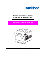
Brother Color Laser Printer
SERVICE MANUAL
MODEL: HL-4200CN
Read this manual thoroughly before maintenance work.
Keep this manual in a convenient place for quick and easy reference at all times.
November 7, 2004
SM-PRN038
© Copyright Brother 2003
All rights reserved.
No part of this publication may be reproduced in any form or by any means without permission in
writing from the publisher.
Specifications are subject to change without notice.
Trademarks:
The brother logo is a registered trademark of Brother Industries, Ltd.
Apple, the Apple Logo, and Macintosh are trademarks, registered in the United States and other
countries, and True Type is a trademark of Apple computer, Inc.
Epson is a registered trademark and FX-80 and FX-850 are trademarks of Seiko Epson
Corporation.
Hewlett Packard is a registered trademark and HP Laser Jet is a trademark of Hewlett Packard
Company.
IBM, IBM PC and Proprinter are registered trademarks of International Business Machines
Corporation.
Microsoft and MS-DOS are registered trademarks of Microsoft Corporation.
Windows is a registered trademark of Microsoft Corporation in the U.S. and other countries.
PREFACE
This service manual contains basic information required for after-sales service of the color laser
printer (here-in-after referred to as "this machine" or "the printer"). This information is vital to the
service technician to maintain the high printing quality and performance of the printer.
This service manual covers the HL-4200CN color laser printer.
This manual consists of the following chapters:
CHAPTER I :
SPECIFICATIONS
Specifications, etc.
CHAPTER II :
INSTALLATION
Installation conditions and installation procedures.
CHAPTER III :
STRUCTURE OF SYSTEM COMPONENTS
Basic operation of the mechanical system, the electrical system and the
electrical circuits and their timing information.
CHAPTER IV :
ASSEMBLY / DISASSEMBLY
Procedures for replacement of the mechanical system parts.
CHAPTER V :
TROUBLESHOOTING
Description of error messages on the control panel, troubleshooting image
failure, etc.
CHAPTER VI :
DIAGRAMS
CHAPTER VII : PLUG / JACK (P/J) CONNECTOR LOCATIONS
APPENDIX
Information in this manual is subject to change due to improvement or re-design of the product. All
relevant information in such cases will be supplied in service information bulletins (Technical
Information).
A thorough understanding of this printer, based on information in this service manual and service
information bulletins, is required for maintaining its print quality performance and for improving the
practical ability to find the cause of problems.
CONTENTS
CHAPTER I SPECIFICATIONS.........................................................I-1
1. PRODUCT NAME ......................................................................................... I-1
2. OPTIONAL PRODUCTS ............................................................................... I-1
3. DIMENSIONS / WEIGHT (MAIN UNIT)......................................................... I-1
4. BASIC CONFIGURATION............................................................................. I-1
4.1 Engine.................................................................................................................................... I-1
4.2 Feeder Unit ............................................................................................................................ I-2
4.3 Tray Feeder Unit.................................................................................................................... I-3
5. FUNCTIONAL CONFIGURATION ................................................................ I-3
6. ELECTRICAL PROPERTIES ........................................................................ I-4
6.1 Power Source ........................................................................................................................ I-4
6.2 Power Consumption .............................................................................................................. I-4
7. MECHANICAL PROPERTIES....................................................................... I-4
7.1 Dimensions / Mass of Printer................................................................................................. I-4
7.2 Dimensions / Mass of Universal Paper Tray (standard paper supply - 500sheets) .............. I-6
7.3 Dimensions / Mass of Consumables ..................................................................................... I-6
7.4 Installation Space (min. installation space) ........................................................................... I-7
8. FUNCTIONS ................................................................................................. I-8
8.1 Recording System ................................................................................................................. I-8
8.2 Exposure System................................................................................................................... I-8
8.3 Development System............................................................................................................. I-8
8.4 Fixing System ........................................................................................................................ I-8
8.5 Resolution .............................................................................................................................. I-8
8.6 Operation Mode ..................................................................................................................... I-8
8.7 Process Speed ...................................................................................................................... I-9
8.8 Print Mode.............................................................................................................................. I-9
8.9 Paper Mode ......................................................................................................................... I-10
8.10 Warm-up Time ................................................................................................................... I-11
8.11 FPOT (First Print Output Time).......................................................................................... I-11
8.12 Continuous Printing Speed ................................................................................................ I-12
8.13 Printing Area ...................................................................................................................... I-12
8.14 Input Properties ................................................................................................................. I-13
8.15 Output Properties............................................................................................................... I-14
8.16 Paper ................................................................................................................................. I-14
9. CONSUMABLES......................................................................................... I-15
9.1 Items of Consumables ......................................................................................................... I-15
9.2 Consumable Life.................................................................................................................. I-15
9.3 Parts Requiring Periodical Replacement............................................................................. I-16
10. OPERATING ENVIRONMENT.................................................................. I-16
10.1 Installation Temperature / Humidity................................................................................... I-16
10.2 Installation Altitude............................................................................................................. I-16
10.3 Installation Horizontality..................................................................................................... I-16
10.4 Ambient Lighting ................................................................................................................ I-16
11. SAFETY / ENVIRONMENT CONDITIONS................................................ I-16
11.1 Safety Standard ................................................................................................................. I-16
11.2 Laser Safety Standard ....................................................................................................... I-16
11.3 EMI..................................................................................................................................... I-17
11.4 Noise.................................................................................................................................. I-17
12. PRINT IMAGE QUALITY........................................................................... I-17
12.1 Image Quality Guarantee Conditions ................................................................................ I-17
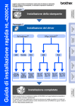
CHAPTER II INSTALLATION...........................................................II-1
1. TRANSPORTING THE PRINTER ................................................................ II-1
2. INSTALLATION PROCEDURE....................................................................II-2
2.1 Checking the Packaged Items.............................................................................................. II-3
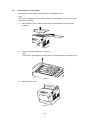
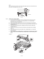
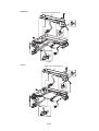
2.2 Removing the Tapes from the Printer................................................................................... II-4
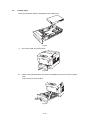
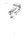
2.3 Removing the Paper Tray Protective Materials .................................................................... II-5
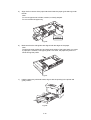
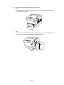
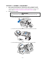
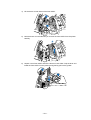
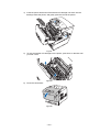
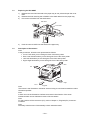
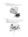
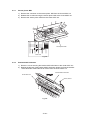
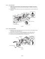
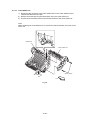
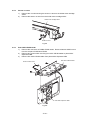
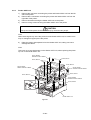
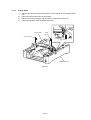
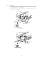
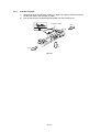
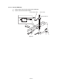
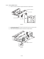
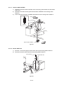
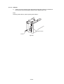
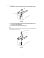
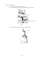
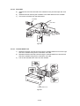
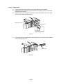
2.4 Mounting the Print Head Cartridge ....................................................................................... II-7
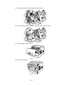
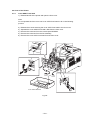
2.5 Preparing the Toner Cartridges .......................................................................................... II-12
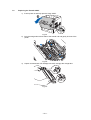
2.6 Loading Paper .................................................................................................................... II-13
2.7 Connecting the Power Code............................................................................................... II-17
2.8 Adjusting Color Registrations ............................................................................................. II-18
CHAPTER III STRUCTURE OF SYSTEM COMPONENTS ............III-1
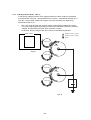
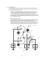
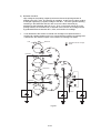
1. PRINTING PROCESS ................................................................................ III-1
1.1 Summary of Printing Process .............................................................................................. III-1
1.2 Schematic Diagram for Printing Processes ......................................................................... III-3
1.3 Description of Printing Process Techniques........................................................................ III-4
2. FLOW OF PRINT DATA ............................................................................ III-17
2.1 Data Flow........................................................................................................................... III-17
3. DRIVE TRANSMISSION ROUTE.............................................................. III-18
3.1 Drive ASSY main ............................................................................................................... III-18
3.2 Drive ASSY DEVE ............................................................................................................. III-19
3.3 Holder Toner Cartridge ASSY (Y, M, C, K) ....................................................................... III-19
3.4 Fuser Drive ASSY.............................................................................................................. III-20
3.5 Motor ASSY DUP............................................................................................................... III-20
3.6 Gear Layout ....................................................................................................................... III-21
4. PAPER TRANSFER .................................................................................. III-22
4.1 Paper Transfer Route (without option) .............................................................................. III-22
4.2 Layout of Paper Transfer Route ........................................................................................ III-23
5. FUNCTIONS OF MAJOR FUNCTIONAL COMPONENTS ........................ III-24
5.1 Paper Cassette .................................................................................................................. III-25
5.2 Paper Feeder ..................................................................................................................... III-26
5.3 Housing ASSY Retard ....................................................................................................... III-28
5.4 Front ASSY In .................................................................................................................... III-29
5.5 Chute ASSY Out ................................................................................................................ III-30
5.6 Chute ASSY Exit................................................................................................................ III-32
5.7 Transfer Roll Cartridge ASSY & Fuser .............................................................................. III-33
5.8 Xerographics...................................................................................................................... III-35
5.9 Toner Cartridge ASSY ....................................................................................................... III-37
5.10 Frame & Drive.................................................................................................................. III-39
5.11 Electrical .......................................................................................................................... III-40
6. MODES..................................................................................................... III-42
6.1 Print Mode.......................................................................................................................... III-42
6.2 Operation Modes ............................................................................................................... III-42
7. CONTROL................................................................................................. III-43
7.1 Control of Paper Size......................................................................................................... III-43
7.2 Selective Control on Paper Pick-up Unit ........................................................................... III-43
7.3 Scanner Light Quantity Control ......................................................................................... III-43
7.4 Process Control ................................................................................................................. III-44
7.5 Color Registration Control ................................................................................................. III-47
7.6 Transfer Roll Cartridge Unit ASSY Control........................................................................ III-48
7.7 Toner Control ..................................................................................................................... III-49
7.8 Fuser Control ..................................................................................................................... III-50
CHAPTER IV ASSEMBLY / DISASSEMBLY............................... IV-1
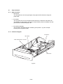
1. REPLACING PROCEDURE OF PERIODICAL REPLACEMENT PARTS ........... IV-1
1.1
1.2
1.3
1.4
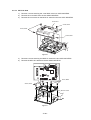
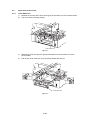
Replacing the Fuser ASSY .................................................................................................IV-1
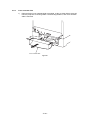
Replacing the Transfer ASSY.............................................................................................IV-4
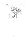
Replacing the Roll ASSY ....................................................................................................IV-6
Description of Procedures ..................................................................................................IV-6
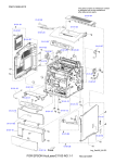
2. DISASSEMBLY PROCEDURE .................................................................. IV-6
2.1 Precautions ..........................................................................................................................IV-7
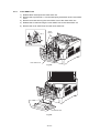
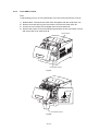
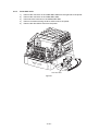
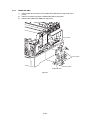
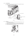
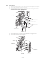
2.2 Cover of the Printer.............................................................................................................IV-8
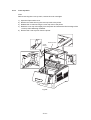
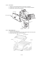
2.3 Front of the Printer ............................................................................................................IV-19
2.4 Top of the Printer ..............................................................................................................IV-45
2.5 Right / Left / PCBs of the Printer.......................................................................................IV-54
2.6 Paper Feed of the Printer .................................................................................................IV-66
CHAPTER V TROUBLESHOOTING ............................................... V-1
1. PROGRESSING WITH THE TROUBLESHOOTING ...................................................V-1
1.1 Flow of Troubleshooting .......................................................................................................V-1
2. LEVEL 1 FIP ................................................................................................V-2
2.1 Level 1 FIP............................................................................................................................V-2
2.2 Flow of Level 1 FIP ...............................................................................................................V-2
3. LEVEL 2 TROUBLESHOOTING ..................................................................V-3
3.1 Level 2 FIP............................................................................................................................V-3
3.2 Fail Code List ........................................................................................................................V-3
3.3 Error Code FIP....................................................................................................................V-13
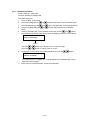
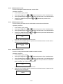
4. HOW TO USE DIAG. (C/E) MODE ............................................................V-38
4.1 Roles of the Control Panel in Diag. (C/E) Mode.................................................................V-38
4.2 Entering Diag. (C/E) Mode..................................................................................................V-38
4.3 Exiting Diag. (C/E) Mode ....................................................................................................V-38
4.4 Diag. (C/E) Mode Functions ...............................................................................................V-38
4.5 Operation Procedure ..........................................................................................................V-39
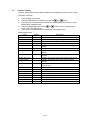
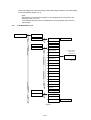
4.6 Diag. Mode Menu Tree .......................................................................................................V-40
4.7 ESS Diagnosis ....................................................................................................................V-42
4.8 IOT Diagnosis .....................................................................................................................V-43
4.9 Installation Setting ..............................................................................................................V-53
4.10 Test Print...........................................................................................................................V-54
4.11 Parameter Setting.............................................................................................................V-55
4.12 Information Print ...............................................................................................................V-57
5. DIAGNOSIS FOR STANDALONE PRINTER.............................................V-59
5.1 General ...............................................................................................................................V-59
5.2 Printing Method...................................................................................................................V-59
5.3 Test Print Pattern ................................................................................................................V-60
6. TRANSFER ROLL CARTRIDGE ADJUSTING THIRD TRANSFER
CURRENT VALUE .....................................................................................V-61
6.1 Procedure of Changing the Transfer Current Value Setup ................................................V-61
6.2 User Mode Menu Tree........................................................................................................V-63
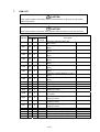
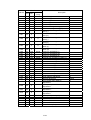
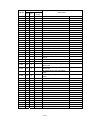
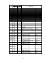
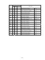
7. NVM LIST ..................................................................................................V-64
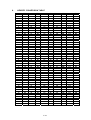
8. HEX/DEC CONVERSION TABLE..............................................................V-70
9. IMAGE QUALITY TROUBLE ENTRY CHART ...........................................V-72
10. IMAGE QUALITY SPECIFICATIONS ......................................................V-73
10.1 Parallelism ........................................................................................................................V-73
10.2 Diagonal............................................................................................................................V-73
10.3 Skew .................................................................................................................................V-73
10.4 Straightness ......................................................................................................................V-74
10.5 Magnification Error............................................................................................................V-74
10.6 Registration.......................................................................................................................V-74
10.7 Guaranteed Printing Area .................................................................................................V-75
11. TEST PRINT ............................................................................................V-76
11.1 Test print ...........................................................................................................................V-76
12. IMAGE QUALITY FIP...............................................................................V-77
12.1 Notes on Image Quality Trouble Check............................................................................V-77
12.2 Basic Rule of Image Quality Adjustment ..........................................................................V-77
12.3 Troubleshooting Table by Trouble Phenomena ...............................................................V-78
CHAPTER VI DIAGRAMS .............................................................. VI-1
1.PREFACE ....................................................................................................VI-1
1.1 How to Use the BSD............................................................................................................VI-1
1.2 Explanations of Symbols .....................................................................................................VI-1
1.3 Signal Name/Other description............................................................................................VI-4
1.4 DC Voltage...........................................................................................................................VI-4
1.5 Input/Output Test .................................................................................................................VI-4
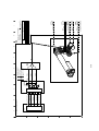
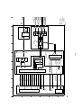
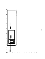
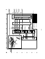
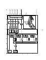
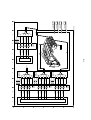
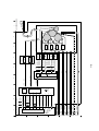
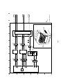
2. BSD (BLOCK SCHEMATIC DIAGRAM)
2.1 Standby Power.....................................................................................................................VI-5
2.2 Mode Selection ....................................................................................................................VI-7
2.3 Machine Run Control ...........................................................................................................VI-8
2.4 Start Print Power................................................................................................................VI-11
2.5 OPTICS (Scanner).............................................................................................................VI-12
2.6 Paper Supplying ................................................................................................................VI-14
2.7 Paper Transportation .........................................................................................................VI-19
2.8 XEROGRAPHICS..............................................................................................................VI-28
2.9 Fusing and Transportation.................................................................................................VI-36
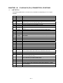
CHAPTER VII PLUG/JACK (P/J) CONNECTOR LOCATIONS.... VII-1
1. LIST OF P/J ...............................................................................................VII-1
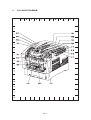
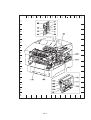
2. P/J LAYOUT DIAGRAM .............................................................................VII-4
APPENDIX 1 ............................................................................. APP-1
1.1 When PCB is replaced.........................................................................................................A-1
1.2 Controller Firmware upgrade...............................................................................................A-2
APPENDIX 2 CONSUMABLES REPLACEMENT .................... APP-2
1. Coverage ................................................................................................................................A-7
2. Job ..........................................................................................................................................A-8
APPENDIX 3 HOW TO USE THE CLEANING KIT TO REMOVE
25MM PITCH COLOR DOTS ..................................................... APP-3
APPENDIX 4 MEASURE OF TONER CARTRIDGE WEIGHT . APP-4
APPENDIX 5 PERIODICAL REPLACEMENT PARTS ............ APP-5
REGULATIONS
LASER SAFETY (FOR 120 V MODEL ONLY)
This printer is certified as a Class I laser product under the U.S. Department of Health and
Human Services (DHHS) Radiation Performance Standard according to the Radiation
Control for Health and Safety Act of 1968. This means that the printer does not produce
hazardous laser radiation.
Since radiation emitted inside the printer is completely confined within protective housings
and external covers, the laser beam cannot escape from the machine during any phase of
user operation. However, the machine contains 5-milliwat, 700-800 nanometer
wavelength, GaAIAs laser diodes. Direct (or indirect reflected) eye contact with the laser
beam might cause serious eye damage. Safety precautions and interlock mechanisms
have been designed to prevent any possible laser beam exposure to the operator.
FDA REGULATIONS (FOR 120 V MODEL ONLY)
U.S. Food and Drug Administration (FDA) has implemented regulations for laser products
manufactured on and after August 2, 1976. Compliance is mandatory for products
marketed in the United States. The label shown on the back of the printer indicates
compliance with the FDA regulations and must be attached to laser products marketed in
the United States.
MANUFACTURED:
BROTHER INDUSTRIES, LTD.
15-1 Naeshiro-cho, Mizuho-ku, Nagoya, 467-8561 Japan
This product complies with FDA radiation performance standards, 21 CFR
Subchapter J.
Caution:
Use of controls, adjustments or the performance of procedures other than those specified
in this manual may result in hazardous radiation exposure.
i
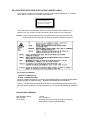
IEC 60825 SPECIFICATION (FOR 220-240 V MODEL ONLY)
This printer is a Class 1 laser product as defined in IEC 60825 specifications. The label
shown below is attached in countries where required.
CLASS 1LASER PRODUCT
APPAREIL Å LASER DE CLASSE 1
LASER KLASSE 1 PRODUKT
This printer has a Class 3B Laser Diode which emits invisible laser radiation in the
Scanner Unit. The Scanner Unit should not be opened under any circumstances.
Caution: Use of controls, adjustments or the performance of procedures other than
those specified in this manual may result in hazardous radiation exposure.
For Finland and Sweden
LUOKAN 1 LASERLAITE
KLASS 1 LASER APPARAT
Varoitus! Laitteen käyttäminen muulla kuin tässä käyttöohjeessa mainitulla tavalla saattaa
altistaa käyttäjän turvallisuusluokan 1 ylittävälle näkymättömälle lasersäteilylle.
Varning – Om apparaten används på annat sätt än i denna Bruksanvisning specificerats,
kan användaren utsättas för osynlig laserstrålning, som överskrider gränsen för laserklass
1.
Internal laser radiation
Max. Radiation Power
Wave Length
Laser Class
10 mW
770 nm-808 nm
Class IIIb (Accordance with 21 CFR Part 1040.10)
Class 3B (Accordance with IEC60825)
ii
SAFETY
To prevent possible accidents during maintenance operation, you should observe strictly
the "Warning" and "Caution" information in this manual.
Dangerous operations and operations out of range of this manual should be absolutely
avoided.
Generally various processes not covered by this manual may be required in actual
operation, which should be performed carefully always giving attention to safety.
Caution
Use of controls or adjustment or performance of procedures other than those specified in
this manual might result in hazardous radiation exposure.
Disconnect device
This printer must be installed near a power outlet that is easily accessible. In case of
emergencies, you must disconnect the power cord from the power outlet to shut off the
power completely.
Caution for batteries
Do not replace the battery. There is a danger of explosion if the battery is incorrectly
replaced. Do not disassemble, recharge or dispose of inby fire. Used batteries should be
disposed of according to local regulations.
iii
Power Source
Keep the power supply off during maintenance operation to prevent electric shock, burns
and other damages. Keep the power plug disconnected during the maintenance
operation.
If the power supply should be kept connected for measurement of voltage or other similar
reasons, sufficient care should be given to prevent electric shock, by following the
procedures of this manual.
WARNING
While the printer is ON, never touch live parts if not required absolutely.
WARNING
Power is supplied to the power switch / inlet (LVPS ASSY) even while the printer is off.
Never touch its live components.
WARNING
Do not touch live parts unless otherwise specified.
Driving Units
When servicing gears or other driving units, be sure to turn them OFF and plug off. Drive
them manually when required.
WARNING
Never touch the gears or other driving units while the printer is running.
iv
High-temperature Units
When servicing high-temperature units (securing unit, etc.), be sure to turn them OFF to
prevent burns, injuries and other troubles, remove the power plug and start service
processes after they have cooled down enough.
WARNING
Immediately after completion of operation, they are still hot. Start services after more than
40 minutes.
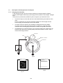
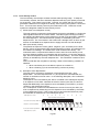
Laser Beams
WARNING
•
•
•
•
If your eyes are exposed to laser beams, you may lose your eyesight.
Never open the cover if warning label for laser beams is attached there.
Before disassembling and reassembling this laser printer, be sure to turn it OFF.
When servicing this laser printer while it is running, be sure to follow the procedures
specified in this manual.
• You should understand the features of the laser beams which are capable of having an
injurious action on the human body, not to extend the danger over the workers as well
as other people around the printer.
Note:
Laser beams have features as follows:
• Frequencies are smaller in width than other beams (sun and electric bulbs) and phases
are uniform so that high monochromatic and convergence performance can be
obtained and thin beams of light can reach places at a long distance.
• Due to the high convergence, beams are concentrated in high density and high
temperature, which is dangerous to human body.
Reference: Laser beams of this laser printer is invisible rays which you cannot see.
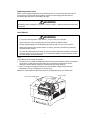
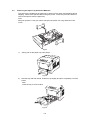
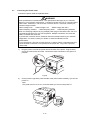
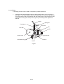
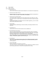
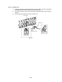
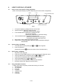
Scanner ASSY
Print Head Cartridge ASSY
v
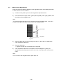
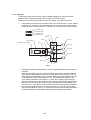
Warning/Caution Labels
Warning labels and caution labels are attached to this laser printer to prevent accidents
check those labels for their peeling or stain when servicing the printer.
< Caution label for high-temperature units >
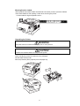
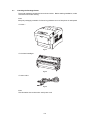
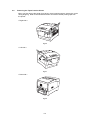
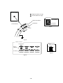
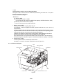
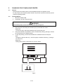
Unpacking the Printer
WARNING
The printer must be carried horizontally by two or more persons.
CAUTION
Extreme care must be taken to avoid personal injuries.
Check visually the printer for evidence of any damages.
Peel all tapes off the printer.
Remove protection parts (2 pieces) from the paper tray.
vi
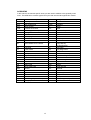
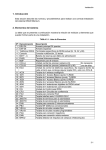
ACRONYMS
In this manual, the manual specific acronyms are used in addition to the generally used
ones. The table below contains typical acronyms that are used throughout this manual.
ADC
AUX.
BCR
BUR
CCW
CLN
CR
CRUM
DB
FG
Hex
IDT
Automatic Density Control
Auxiliary
Bias Charge Roll
Back Up Roll
Counter Clock Wise
Cleaning (or Cleaner)
Charge Roll
CRU Monitor
Developing Bias
Frame Ground
Hexadecimal
Intermediate Drum Transfer
AG
B/W
CART.
CL.
CLK
CRU
CW
DTS
FDR
FRU
I/F
ID
L/H
LD
MSI
N/P
OPC
PCDC
Pixel
PV
R/H
SEF
SNR
SOS
SYNC.
TC
TR
WDD
XERO.
Left Hand
Laser Diode
Multi Sheet Inserter
No Paper
Organic Photo Conductor
Pixel Count Dispense Control
Picture Cell
Print Volume
Right Hand
Short Edge Feed
Sensor
Start Of Scan
Synchronous
Toner Concentration
Transfer
Wide Range Dynamic Damper
Xerographic
L/P
LEF
N/F
NVM
P/H
PPM
PWB
REGI.
RTN
SG
SOL.
SPI
T/A
TEMP.
TRANS.
YMCBk
vii
Analog Ground
Black and White
Cartridge
Clutch
Clock
Customer Replaceable Unit
Clock Wise
Detack Saw
Feeder
Field Replaceable Unit
Interface
Image Density
(or Identification)
Low Paper
Long Edge Feed
Normal Force
Non Volatile Memory
Paper Handling
Prints Per Minute
Printed Wiring Board
Registration
Return
Signal Ground
Solenoid
Scans Per Inch
Take Away
Temperature
Transport
Yellow, Magenta, Cyan, Black
Service call procedures
1.
Notes Before Work
1.1 Safety notes
To prevent an accident during maintenance, follow warnings and precautions strictly.
Avoid dangerous work.
1. Power supply
To prevent an electric shock, burn, or injury, turn off the power and unplug the
power cable before maintenance work. If it is inevitable to keep the power on for
voltage measurement, take the greatest care not to receive an electric shock.
2. Drive
Never inspect or lubricate drive components such as gears when the machine is
in operation.
3. Heavy parts
The machine weighs 34.9 kg. When lifting the machine, get a firm footing and
bend your knees to avoid possible injuries to your back.
4. Safety devices
Ensure the safety functions of safety devices for preventing mechanical accidents
(fuses, circuit breakers, and interlock switches) and for safe user operations
(panels and covers). Do not make mechanical alterations that may impair the
safety functions.
5. Parts mounting and removal
Parts and covers may have sharp edges. Do not touch the edges readily. If your
fingers or hands become greasy, wipe off the grease well. Do not pullout a part
cable forcibly but gradually.
6. Specified tool
Follow instructions if a tool is specified.
7. Organic solvents
Use the drum cleaner and other organic solvents carefully with the following notes
in mind:
• Keep the room well ventilated not to breathe in vapor a lot or continuously.
• The solvents are inflammable liquids. Do not put them close to or into a fire or
do not heat their containers.
• Avoid storing the solvents near a naked fire or sparks because they may catch
fire.
8. Irregular use of machine
When altering the machine, submit an application for irregular use in advance.
viii
1.2 Other notes
Do maintenance work correctly and efficiently with the following notes in mind:
1. Reference materials
Read the related technical information (SB, FTI, FTO and so on) well and do
maintenance work systematically.
2. Disassembling
Before removing parts for disassembling, check the normal mounting status in
advance.
3. Mounting and adjustment
Do not start up the machine immediately after finishing part mountings and
adjustments. Check that there are no tools or parts left inside the machine or on
assy.
4. Handling of replaced parts and consumables
Do not discard of replaced parts and consumables at the customer site.
After replacing the following consumables, be sure to attach the U tag to the
replaced one and recover.
Drum cartridge
Color toner cartridges
As to parts to be recycled, enter necessary data into the U tag and recover the
parts.
5. General Notes
Be careful not to disturb the customer's daily work.
Color toner dropped on the floor is hardly cleaned. Place the drop cloth on the
floor when maintaining the inside of the machine to protect carpets and floors.
Put wastes, consumables, and replaced parts into a plastic or paper bag and
obtain the permission of the customer to throw them away.
Be sure to enter the field work contents and the replaced consumables and parts
into the Machine Log Book.
HL-4200CN weighs 34.9 kg.
When moving the equipment, make sure that there are two or more persons carrying it.
For details, see the installation procedure on page II-1.
ix
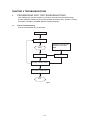
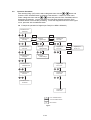
2.
Workflow in the Field
< Initial Actions >
1.
2.
3.
4.
Question the Customer for details about the system malfunction.
Note down the meter count.
Inspect the rejected print and determine the machine condition.
Check the Machine Log Book.
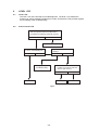
< For UM visit >
1. Perform the Level 1 troubleshooting.
2. Perform the troubleshooting.
3. Print any Internal Test Pattern to check the print quality. (See page V-54)
4. Feed paper from each tray, and clean or replace the feed role as required.
5. Repair any secondary problems that would prevent the machine from running.
6. Perform the trim activities.
< For SM visit >
1. Print any Internal Test Pattern to check the print quality. (See page V-54)
2. Feed paper from each tray, and clean or replace the feed role as required.
3. Repair any secondary problems that would prevent the machine from running.
4. Perform the trim activities.
< Final Actions >
1. Check the machine overall operation and function.
2. Check the machine appearance and consumables.
3. Perform the operator training as required.
4. Record the performed action in the Machine Log Book and Service Report.
5. Store the sample printouts in the Machine Log Book.
x
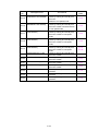
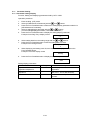
3.
Trim Activity
Trim activities for HL-4200CN should be made within every SM/UM, mainly for
maintaining the machine performance. There is no service call performed only for
the trim activity.
3.1 Trim activity procedure
1. Check the overall operation before performing the trim activity.
Print any Internal Test Pattern to output three patterns: all colors of 20 % each,
halftone and grid.
All colors of 20 % each: IBT belt, scratches on the drum surface, and fusing
problem are checked.
Halftone pattern: Low density area reproduction problem, color balance and
fusing problem are checked.
Grid pattern: Color registration problem and fusing problem are checked.
* See page V-54 for test pattern output method.
2. Clean the interior of the machine.
Clean toner contamination and paper dust in the paper path area.
(Operator area should be cleaned carefully.)
3. Check the periodic replacement parts(consumable parts). Replace as required.
4. Safety check.
Check the Power Cord for damage or loose connection.
5. After 1 to 4 above completes, do the following overall operation checks.
Machine operation
Print quality
Meter reading
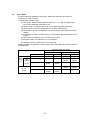
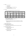
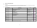
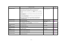
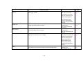
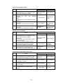
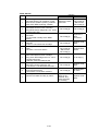
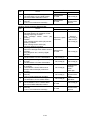
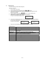
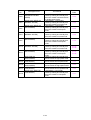
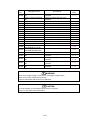
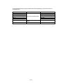
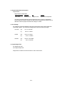
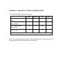
3.2 Mechanical consumables and periodic replacement parts
A mechanical consumable should be replaced after checking the printed sheets
count during trim action.
<Mechanical consumables>
Consumable
Product Code
Number of sheets that can be
printed*1
Black Toner Cartridge
TN-12CL
9K
Cyan Toner Cartridge
TN-12CL
6K
Magenta Toner Cartridge
TN-12CL
6K
Yellow Toner Cartridge
TN-12CL
6K
Print Head Cartridge
PH-12CL
30K
Transfer Roll Cartridge
TR-11CL
25K
(with Waste Toner Pack)
Fixing Parts
FP-12CL
100K
*1: Condition
Paper size: A4 or LETTER
Toner coverage: 5%
Ratio of B/W to color: 1: 1
Average number of sheets printed at onetime: 4 sheets
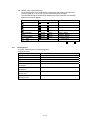
<Parts for periodic replacement>
Consumable
Replacement interval
Fuser Unit
100K prints
Retard Roll
100K prints
xi
Remarks
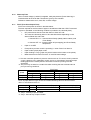
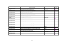
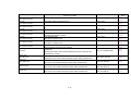
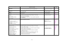
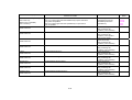
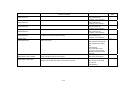
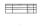
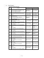
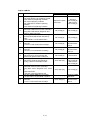
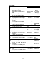
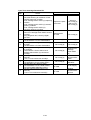
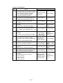
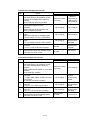
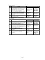
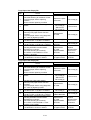
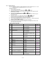
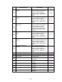
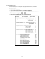
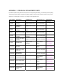
3.3 Trim checklist
C: Check and if necessary clean, replace, or replenish.
A: Always check and clean.
R: Replace at specified intervals.
* See page V-54 for the test pattern output method.
No.
Work item
Each
time
100K
Rep &
Adj
No.
1.1
Check before work
(Mechanical noise
check)
C
- Start up the machine to see that no
abnormal noise occurs
1.2
Check before work
(Test pattern output)
C
2
Cleaning inside the
machine
(Paper transport
system cleaning)
Retard Roll
C
R
- Output the internal test patterns to check
the print quality.
(Check uneven darkness, deletion, and
drum of belt damage with each 20%
pattern and reproducibility of low darkness
with the document reproducibility pattern.)
- Clean any loose toner and paper dust from
the paper transport path and jam sensors.
- Clean especially the operator area.
- Check and clean the MSI field roll.
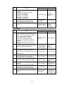
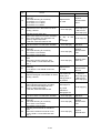
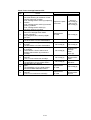
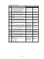
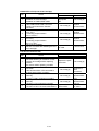
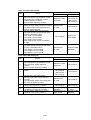
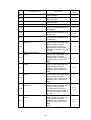
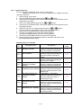
3.1
Fuser ASSY
A
R
- Check that the H. Roll and P. Roll are not
scratched.
Replace them when necessary.
3.2
Print Head Cartridge
A
30K
- Visual check only. Do not touch.
3.3
Transfer Roll
Cartridge Unit ASSY
C
18K
- Visual check only. Do not touch.
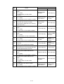
4
Safety check
A
- Check the power plug for loose
connection.
- Check the power cable for crack or
explosion of its conductor.
- Check that the extension cable of an
insufficient capacity or a nonstandard
power cable (ex. table tap) is not used.
- Check that the power cable is not
connected to the same outlet as some
other cables.
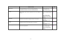
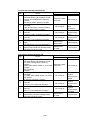
5.1
Check after work
(Print quality check)
C
- Output the internal test patterns to see that
the print quality satisfies the standards.
5.2
Check after work
(Machine operation
check)
C
- Check paper feed and noise.
5.3
Check after work
C
- Create Machine Log Book and a service
report.
Description
CAUTION
Do not touch the print head cartridge or transfer roll cartridge unit directly by hand.
Do not use a drum cleaner or other solvents. (It will take time for the machine to recover.)
xii
CHAPTER I
SPECIFICATIONS
CONTENTS
CHAPTER I SPECIFICATIONS.........................................................I-1
1. PRODUCT NAME ............................................................................................ I-1
2. OPTIONAL PRODUCTS .................................................................................. I-1
3. DIMENSIONS / WEIGHT (MAIN UNIT)............................................................ I-1
4. BASIC CONFIGURATION ............................................................................... I-1
4.1 Engine.................................................................................................................................... I-1
4.2 Feeder Unit ............................................................................................................................ I-2
4.3 Tray Feeder Unit.................................................................................................................... I-3
5. FUNCTIONAL CONFIGURATION ................................................................... I-3
6. ELECTRICAL PROPERTIES ........................................................................... I-4
6.1 Power Source ........................................................................................................................ I-4
6.2 Power Consumption .............................................................................................................. I-4
7. MECHANICAL PROPERTIES.......................................................................... I-4
7.1 Dimensions / Mass of Printer................................................................................................. I-4
7.2 Dimensions / Mass of Universal Paper Tray (standard paper supply - 500sheets) .............. I-6
7.3 Dimensions / Mass of Consumables ..................................................................................... I-6
7.3.1 Print head cartridge......................................................................................................... I-6
7.3.2 Transfer roll cartridge...................................................................................................... I-6
7.3.3 Toner cartridge................................................................................................................ I-7
7.4 Installation Space (min. installation space) ........................................................................... I-7
8. FUNCTIONS .................................................................................................... I-8
8.1 Recording System ................................................................................................................. I-8
8.2 Exposure System................................................................................................................... I-8
8.3 Development System............................................................................................................. I-8
8.4 Fixing System ........................................................................................................................ I-8
8.5 Resolution .............................................................................................................................. I-8
8.6 Operation Mode ..................................................................................................................... I-8
8.7 Process Speed ...................................................................................................................... I-9
8.8 Print Mode.............................................................................................................................. I-9
8.9 Paper Mode ......................................................................................................................... I-10
8.10 Warm-up Time ................................................................................................................... I-11
8.11 FPOT (First Print Output Time).......................................................................................... I-11
8.12 Continuous Printing Speed ................................................................................................ I-12
8.13 Printing Area ...................................................................................................................... I-12
8.13.1 Usable paper size ....................................................................................................... I-12
8.13.2 Maximum printable area ............................................................................................. I-12
8.13.3 Guaranteed printing area ............................................................................................ I-13
8.14 Input Properties ................................................................................................................. I-13
8.14.1 Paper pick-up system ................................................................................................. I-13
8.14.2 Paper pick-up capacity................................................................................................ I-13
8.15 Output Properties............................................................................................................... I-14
8.15.1 Paper delivery system................................................................................................. I-14
8.15.2 Paper delivery capacity............................................................................................... I-14
8.15.3 Delivery paper size/mass............................................................................................ I-14
8.15.4 Full stack detection ..................................................................................................... I-14
8.16 Paper ................................................................................................................................. I-14
8.16.1 Paper type................................................................................................................... I-14
8.16.2 Paper mass ................................................................................................................. I-14
8.16.3 Paper size ................................................................................................................... I-15
9. CONSUMABLES............................................................................................ I-15
9.1 Items of Consumables ......................................................................................................... I-15
9.2 Consumable Life.................................................................................................................. I-15
9.3 Parts Requiring Periodical Replacement............................................................................. I-16
10. OPERATING ENVIRONMENT..................................................................... I-16
10.1 Installation Temperature / Humidity................................................................................... I-16
10.2 Installation Altitude............................................................................................................. I-16
10.3 Installation Horizontality..................................................................................................... I-16
10.4 Ambient Lighting ................................................................................................................ I-16
11. SAFETY / ENVIRONMENT CONDITIONS................................................... I-16
11.1 Safety Standard ................................................................................................................. I-16
11.2 Laser Safety Standard ....................................................................................................... I-16
11.3 EMI..................................................................................................................................... I-17
11.4 Noise.................................................................................................................................. I-17
12. PRINT IMAGE QUALITY.............................................................................. I-17
12.1 Image Quality Guarantee Conditions ................................................................................ I-17
12.1.1 Environmental conditions............................................................................................ I-17
12.1.2 Guaranteed paper....................................................................................................... I-18
12.1.3 Paper condition ........................................................................................................... I-18
12.1.4 Printer condition .......................................................................................................... I-18
12.1.5 Image quality guaranteed area ................................................................................... I-18
12.1.6 Criterion....................................................................................................................... I-18
CHAPTER I SPECIFICATIONS
1.
PRODUCT NAME
Product Name
HL-4200CN
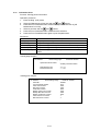
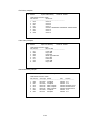
2.
OPTIONAL PRODUCTS
No.
1
2
3
3.
Product Code
54S602
Product Name
1 x 500 – sheet tray
2 x 500 – sheet tray
Hard Disk
Product Code
LT-41CL
LT-42CL
HD-41CL
4.1
20GB
DIMENSIONS / WEIGHT (MAIN UNIT)
Width (mm)
Depth (mm) Height (mm)
439
590*
445
*: with the manual tray folded
4.
Remarks
Weight (kg)
34.9kg or less (incl. Print Head)
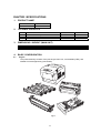
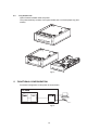
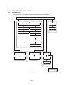
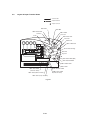
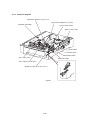
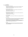
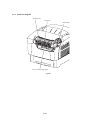
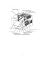
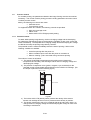
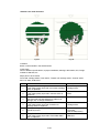
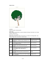
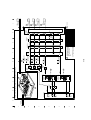
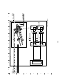
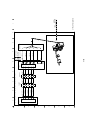
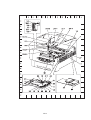
BASIC CONFIGURATION
Engine
This printer basically consists of the print engine main unit, consumables (CRU), and
standard universal paper tray (500 sheets).
Fig.1-1
I-1
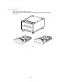
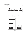
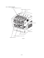
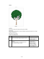
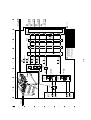
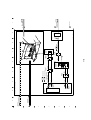
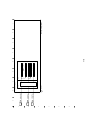
4.2
Feeder Unit
Option Feeder installed under the printer.
This printer basically consists of an option feeder and two universal paper tray (500
sheets each).
Fig.1-2
I-2
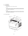
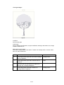
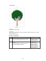
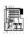
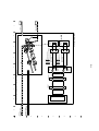
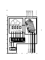
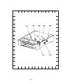
4.3
Tray Feeder Unit
Option Feeder installed under the printer.
This printer basically consists of an option feeder and a universal paper tray (500
sheets).
Fig.1-3
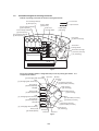
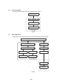
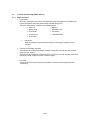
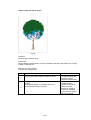
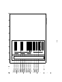
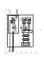
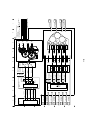
5.
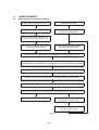
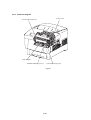
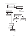
FUNCTIONAL CONFIGURATION
Functional configuration of this printer is shown below.
Fig.1-4
I-3
6.
6.1
ELECTRICAL PROPERTIES
Power Source
Two types of power source as follows are available for this printer, which are selected
according to the specifications.
* 100V/120V printer: Voltage: 100-127VAC ±10% (90 to 140V), frequency: 50/60Hz ±
3Hz
* 220/240V printer: Voltage: 220-240VAC ±10% (198 to 264V), frequency: 50/60Hz ±
3Hz
6.2
Power Consumption
Power consumption in each operation mode at rated voltage input
Operation mode
Printing mode
(Running mode)
Average (Wh/h) *1
READY mode
(Ready mode)
ENAGISTAR mode *2
Max. power consumption
600W
900W
(Fuser is on)
180W
900W
(Fuser is on)
--
45W
(Controller is included)
*1 At running mode : wattage per hour at printing continuously.
At ready mode : wattage per hour at the temperature of fuser ready.
*2 Fuser is in stop status.
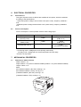
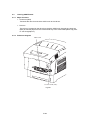
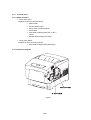
7.
7.1
MECHANICAL PROPERTIES
Dimensions / Mass of Printer
Width: 439mm ± 1%
Depth: 590mm ± 1% (with no cassette installed), 638mm ± 1% (with cassette installed)
Height: 445mm ± 1%
Mass
(No cassette installed + (No CRU): 26.8 kg ± 1%
(No cassette installed + (CRU): 32.5 kg ± 1%
(Cassette installed + (No CRU): 29.2 kg ± 1%
(Cassette installed + CRU): 34.9kg ± 1%
Fig.1-5
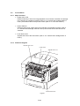
I-4
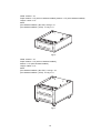
Width: 439mm ± 1%
Depth: 509mm ± 1% (with no cassette installed), 563mm ± 1% (with cassette installed)
Height: 172mm ± 1%
Mass
(No cassette installed + (No CRU): 9.3kg ± 1%
(No cassette installed + (CRU): 11.8 kg ± 1%
Fig.1-6
Width: 439mm ± 1%
Depth: 509mm ± 1% (with no cassette installed),
563mm ± 1% (with cassette installed)
Height: 336mm ± 1%
Mass
(No cassette installed + (No CRU): 14.2 kg ± 1%
(No cassette installed + (CRU): 19.2 kg ± 1%
Fig.1-7
I-5
7.2
Dimensions / Mass of Universal Paper Tray (standard paper supply – 500sheets)
Width: 321mm ± 1%
Depth: 558mm ± 1%
Height: 97mm ± 1%
Mass: 2.5kg ± 1%
Fig.1-8
7.3
Dimensions / Mass of Consumables
7.3.1
Print head cartridge
Width: 339mm ± 3mm
Depth: 146mm ± 3mm
Height: 179mm ± 3mm
Mass: 4.5kg ± 0.1kg
Reference: The print head cartridge has CRUM (CRU memory) to record information.
Fig.1-9
7.3.2
Transfer roll cartridge
Width:309mm ± 3mm
Depth:85mm ± 3mm
Height:60mm ± 3mm
Mass:500g ± 10g
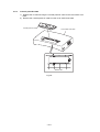
Fig.1-10
I-6
7.3.3
Toner cartridge
Black toner cartridge
Yellow toner cartridge
Magenta toner cartridge
Cyan toner cartridge
Width
355mm ± 3mm
355mm ± 3mm
355mm ± 3mm
355mm ± 3mm
Depth
51mm ± 3mm
51mm ± 3mm
51mm ± 3mm
51mm ± 3mm
Height
55mm ± 3mm
55mm ± 3mm
55mm ± 3mm
55mm ± 3mm
Mass
360g ± 10g
315g ± 10g
325g ± 10g
315g ± 10g
Fig.1-11
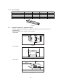
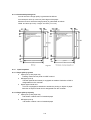
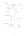
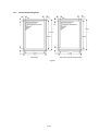
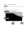
7.4
Installation Space (min. installation space)
Minimum space as shown below is required to install the printer when it is used for
normal objects.
(Space occupied by the operator is not included.)
<Top view>
100mm
600mm
200mm
150mm
Fig.1-12
<Front view>
100mm
150mm
Fig.1-13
<Side view>
350mm
600mm
200mm
Fig.1-14
I-7
8.
8.1
FUNCTIONS
Recording System
OPC drum, 4-tandem cartridges, electro-photographic system using intermediate
transfer rolls
8.2
Exposure System
Semiconductor laser, simultaneous scanning by 4 beams
8.3
Development System
Development with dry type 2-component developer
8.4
Fixing System
Heat fusing of the free belt nip system
8.5
Resolution
Two types of resolutions can be switched. Printing speed is halved at 1200dpi
* Main scanning direction: 600 dots/25.4mm (by video signal from controller)
1200 dots/25.4mm (by video signal from controller)
(Half speed)
* Sub scanning direction: 600 dots/25.4mm (fixed)
1200 dots/25.4mm (fixed) (Half speed)
8.6
Operation Mode
The printer can be operated in either of 2 operation modes. The modes are switched
over by command from the printer controller or change of printer operation, etc.
* Running mode
State in running or recording operation
Fixing system:
Held at operating temperature.
Exposure system:
Operating status
Recording system:
Operating status
Fuser fan:
Operating at high speed
Rear fan:
Operating at high speed
* Ready mode
Ready state
Fixing system:
Stop status *1
Exposure system:
Stop status *2
Recording system:
Stop status
Fuser fan:
Stop status *3 (Half speed running)
Rear fan:
Stop status *3 (Half speed running)
*1: It can be changed to ready temperature status by a command from a controller.
(However, it needs to be back in a stop status within 2 hours.)
*2: It can be changed to operating status by a command from a controller.
I-8
*3: Fan status is changed depending on the state (temperature, etc.) of the fixing
system.
8.7
Process Speed
The printer prints by switching two levels, Full speed (printing with the highest process
speed of the printer) and Half speed (printing with the half of process speed). The
controller cannot instruct to change the process speed.
8.8
Print Mode
The printer has four modes, Standard mode, Fine mode, High gloss mode, and Super
high gloss mode. Modes are switched over under the instruction from the controller.
(1) Standard mode: used for printing with resolution 600dpi
(2) Fine mode: process direction resolution 1200dpi mode
(3) High gloss mode: thick paper, special paper, and high glossed plain paper
(4) Super high gloss mode: thick paper, special paper, and super high glossed plain
paper
I-9
8.9
Paper Mode
8 paper modes are available for this printer. Modes are switched over under the
instruction from the controller.
<Classification of paper mode>
(1) Plain paper: Japanese plain paper such as FX-P, L, R, J/JD, and plain paper
such as XC-4200 20lb, 24ibs RX-80, 90.
(2) Label-L mode: It is mainly selected to run on Japanese labels (V860 etc.).
(3) Label-H mode: It is mainly selected to run on labels (3R4469 etc.).
(4) Thick paper-L mode: it is selected to run on the papers whose thickness is 106162gsm.
(5) Thick paper-H mode: It is selected to run on the papers whose thickness is 163216gsm.
(6) OHP mode: It is selected to run on OHPs (JE-001 etc).
(7) Envelope mode: It is selected to run on envelopes.
(8) Postcard mode: It is selected to run on postcards.
Relation between the resolution, process speed, print mode and paper mode is shown in
the table below.
Paper mode
Plain
paper
(1)
Thick
paper
(4)-(5)
Special paper
(2)-(3)
(6)-(8)
Print mode
Standard mode
Fine mode
High gloss mode
Fine mode
High gloss mode
Resolution/Process speed
600dpi
1200dpi
Simplex
Duplex
Simplex
Duplex
Full speed Full speed
----Half
Half
speed
speed
Half
Half
--speed
speed
--Half
Half
speed
speed
Half
Half
--speed
speed
I-10
8.10
Warm-up Time
When nominal voltage (115/230V) is applied, ready temperature (Fuser Stand-by) is
reached within 30 seconds after command is given by the controller.
Reference: Measured at 22°C, 55% RH, nominal voltage.
8.11
FPOT (First Print Output Time)
FPOT time of the printer is shown in the table below.
The time required for the first sheet of paper to be delivered after the START command
is given is calculated on the following conditions (rounded to one decimal place).
•
IOT performance that the controller does not have IOT wait.
•
This value is indicated by either of two described below depending on the
status of Motor On and Fuser.
1. Scanner RDY t on : Scanner Motor Ready (steady-status rotation) and
Fuser Ready
2. Scanner OFF t off : Scanner Motor Off (at stopping) and Fuser Ready
temperature
•
Paper is A4 SEF
•
Except when process control is operating*1 / when Fuser Cool down*2
•
Paper mode is plain paper mode.
•
Paper feeding is Tray1 (paper tray which locates at the bottom of the printer)
•
Measurement environment is at 22 °C / 55%RH rated voltage.
*1: Process controller operation is process controls such as TC control, electric potential
control, cleaning cycle, registration control, and so on. Sometimes, the engine stops
feeding papers for a certain period of time while continuous printing for these
operations.
*2: The print may not start for a certain time after receiving the start command due to
prior job running conditions.
Process
speed
Full speed
Half speed
FPOT(sec)
In Simplex mode
In Duplex mode
Scanner RDY t on Scanner OFF t off Scanner RDY t on Scanner OFF t off
8.0
14.0
13.5
19.5
14.5
20.5
24.5
30.5
FPOT of paper fed from trays other than is added following values to above Scanner
RDY t on and Scanner OFF t off .
Process speed
Full speed
Half speed
MSI
-0.3 sec
-0.6 sec
Option Feeder Unit (Tray2) *3
+0.9 sec
+1.8 sec
*3: Tray2 : First tray of option Feeder
*4: Tray3 : Second tray of option Feeder
I-11
Option Feeder Unit(Tray3) *4
+1.8 sec
+3.5 sec
8.12
Continuous Printing Speed
Assuming the time until the trailing end of the 11th sheet is discharged after the trail end
of the 1st sheet is discharged as t seconds, number of printed sheets for a minute given
by the equation [60/t ×10] is shown in the table below, excluding, however, the time for
which the process control is working and during the Fuse Cool Down are not contained.
Note:
This function specifies the IOT performance when the controller did not have the ×2
feeders satisfy the following performance.
Refer to Chart 6 Principles Of Operation, for details of Process control.
Reference:
Unit "PPM" stands for "prints per minute" indicating number of prints per minute.
"ipm" is abbreviation of "Impression Per Min", and indicates "number of printed sides per
minute" for Duplex.
Paper mode
Plain paper
(A4/LET SEF)
Thick paper
(-162gsm)*1
(A4/LET SEF)
Thick paper
(163-216gsm)
/Label/OHP *1
(A4/LET SEF)
Envelop/Postcard
Continuous printing speed
Full speed (600dpi)
Half speed
(600/1200dpi)
Simplex
Duplex
Simplex
Duplex
(ppm)
(ipm)
(ppm)
(ipm)
24/26
15.1/15.4
12/13
7.7/7.9
--
--
12/13
7.7/7.9
--
--
12/13
--
--
--
13
--
*1:In case of small size paper, printing speed is sometimes slowed down.
8.13
Printing Area
8.13.1 Usable paper size
Minimum and maximum paper size usable for this printer are as follows:
Minimum usable paper size:Width 88.9mm (3.5inch) × length 139.7mm (5.5 inch)
(when using MSI).
Maximum usable paper size:Width 215.9mm (8.5 inch) × length 355.6mm (14 inch)
(when using MSI).
8.13.2 Maximum printable area
For each printable size of paper, this printer masks 2.5mm within the left edge and right
edge, 2.0mm from within edge and back edge as unprintable area, in order to prevent
from that images exceed the size of printable area.
Maximum area where image can be printed is as follows:
Width: 210.9mm (8.3 inch) × length: 351.6mm (13.8 inch)
I-12
8.13.3 Guaranteed printing area
Area for which the image quality is guaranteed as follows:
Area except for 4mm (0.1575 inch) from edges of the paper.
Maximum area for which the image quantity is guaranteed as follows:
Width: 207.9mm (8.2 inch) × length: 347.6mm (13.7 inch)
Fig.1-15
8.14
Input Properties
8.14.1 Paper pick-up system
♦
Paper pick-up with paper tray
Feeding method of this printer is ARRF method.
♦
MSI paper pick-up
The MSI (Multi Sheet Inserter) is equipped as standard. Selection of MSI is
designated from the controller.
♦
Duplex paper feeder unit
This unit is equipped as standard to enable the printing on duplex of paper.
Selection of Duplex Feeder Unit is designated from the controller.
8.14.2 Paper pick-up capacity
♦
Paper pick-up with paper tray
500 sheets or below 56mm of standard paper
♦
MSI paper pick-up
100 sheets or below 10mm of standard paper
I-13
8.15
Output Properties
8.15.1 Paper delivery system
♦
FACE DOWN delivery
Paper can be delivered by the following method.
8.15.2 Paper delivery capacity
♦
FACE DOWN delivery
250 sheets (Letter/A4 standard paper)
8.15.3 Delivery paper size/mass
♦
FACE DOWN delivery
All paper sizes applicable to this printer
8.15.4 Full stack detection
♦
8.16
Height of paper to be fed
Detect when the height reached about 36mm.
Paper
8.16.1 Paper type
Paper which can be used with this printer is classified into standard paper, general paper
and special paper.
♦
Standard paper
Using this type of paper is recommended. Reliability, operability and print image
quality are the application range of the specifications.
Following paper is the standard paper.
* Xerox 4200 DP 20lb
* Xerox premier 80g/m²
♦
General paper
General paper is plain paper except standard paper and special paper, and its
reliability and running performance are within the specification, but the print image
quality is out of the specification.
♦
Special paper
Special paper except for plain paper. Reliability and operability are the applicable
range of specifications but the print image quality is out of the applicable range of
specifications.
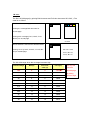
8.16.2 Paper mass
♦
Paper feed from paper tray
"60 to 105 g/m²" (16 - 28 lb)
♦
Paper feed from MSI
"64 to 216 g/m²" (17 - 57 lb)
I-14
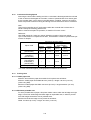
8.16.3 Paper size
Paper size which can be set to each paper pick-up unit is shown in the table below.
Cassette
Paper size
A4 –SEF
B5(JIS) –SEF
A5 -SEF *1
EXECUTIVE –SEF
LETTER –SEF
LEGAL(13")-SEF
LEGAL(14")-SEF
500 Sheet Paper
Universal Tray
MSI Tray
Minimum size
Width 88.9mm(3.5inch)×Length139.7mm(5.5inch)
Maximum size
Width 215.9mm(8.5inch)×Length
355.6mm(14inch)
*1:The end guide which is attached as standard needs to be installed when
running on A5 size paper. The capacity of paper is 350 sheets, or 40mm
or less.
9.
CONSUMABLES
Consumables are usually replaced by costumers. In the event of recovery of failure
attributable to consumables or isolation of failure, you may replace them.
9.1
9.2
Items of Consumables
♦
Print head cartridge
Composed of photosensitive medium, development machine, intermediate
transfer roll, etc.
♦
Transfer roll cartridge
Composed of transfer roll cartridge , waste toner collection box, etc.
♦
Black toner cartridge
Cartridge to supply black toner to the development unit.
♦
Yellow toner cartridge
Cartridge to supply yellow toner to the development unit.
♦
Magenta toner cartridge
Cartridge to supply magenta toner to the development unit.
♦
Cyan toner cartridge
Cartridge to supply cyan toner to the development unit.
Consumable Life
♦
♦
♦
♦
♦
♦
Print head cartridge:
Transfer roll cartridge:
Black toner cartridge:
Yellow toner cartridge:
Magenta toner cartridge:
Cyan toner cartridge:
Equivalent to about 30,000 prints
Equivalent to about 25,000 prints
Equivalent to about 9,000 prints
Equivalent to about 6,000 prints
Equivalent to about 6,000 prints
Equivalent to about 6,000 prints
I-15
9.3
Parts Requiring Periodical Replacement
Following parts are replaced when a certain number of sheets are printed (life over) to
prevent troubles.
♦
♦
♦
♦
♦
♦
♦
♦
Equivalent to about 100,000 prints
Equivalent to about 100,000 prints
Equivalent to about 45,000 prints *1
Equivalent to about 45,000 prints *1
Equivalent to about 300,000 prints
Equivalent to about 300,000 prints
Equivalent to about 300,000 prints *2
Equivalent to about 300,000 prints
Fuser ASSY:
Roll ASSY retard:
Roll ASSY feed MSI :
Roll ASSY retard MSI :
Chute REGI ASSY:
Roll ASSY feed:
Turn roll bearing metal:
Chute ASSY turn:
*1 Replacement life when converting with utilization ratio CST 85% and MSI 15%.
*2 Bearing (ø6×L8)/metal is the same shape as turn roll bearing metal, but it is not
periodical replacement parts.
10. OPERATING ENVIRONMENT
10.1
Installation Temperature / Humidity
Installation temperature and humidity on the condition without condensation is as
follows.
At operating: 5-32 °C, 15-85%RH
At stopping: minus 20-40 °C, 5-85%RH
10.2
Installation Altitude
0 to 3,100m
10.3
Installation Horizontality
Within inclination of 5 degrees
10.4
Ambient Lighting
3000 Lux or less (without no direct sun beams)
11. SAFETY / ENVIRONMENT CONDITIONS
11.1
11.2
Safety Standard
♦
100V / 120V system
UL1950 3rd Edition
CSA C22.2 No.950-M95
♦
220V / 240V system
IEC60950 2nd Edition
Laser Safety Standard
♦
100V / 120V system
FDA21CFR Chapter 1, Subchapter J, Section 1010, 1040
♦
220V / 240V system
IEC60825 Class 1 Laser Product
I-16
11.3
EMI
♦
100V system (JPN)
VCCI Class B
♦
120V system (US)
FCC Part 15, Subpart B, Class B (ANSI C63.4)
220V / 240V system (EC)
EN55022 (CISPR Publication 22), Class B
♦
11.4
Noise
Noise of printing (including simplex, duplex, with option) is as follows.
Process
speed
Full
speed
Half
speed
Printer
(simplex / duplex)
Option
1 Tray Feeder Unit
(simplex / duplex)
Sound
pressure
Sound
level
powerlevel
(By Standar)
Option
Feeder Unit
(simplex / duplex)
Sound
pressure
Sound
level
powerlevel
(By Standar)
Sound
pressure
level
(By Standar)
Sound
powerlevel
55dBA
6.7B
55dBA
6.8B
55dBA
6.9B
52dBA
6.45B
53dBA
6.7B
53dBA
6.7B
Noise of ready mode is as follows.
Sound pressure level (By Standar) 36.5 dBA or less *1
Sound power level 4.95 B or less *1
*1 Both fuser fan and rear fan are on the status of half speed rotation. FAN stops
depending on the status of fuser, and the noise level at this time is the same as
background noise.
12. PRINT IMAGE QUALITY
12.1
Image Quality Guarantee Conditions
The image quality is specified and guaranteed under the following conditions.
12.1.1 Environmental conditions
Environment condition for general office
Temperature: 15-28 °C
Humidity: 20-70%RH
Environment condition for evaluating image quality
Temperature: 10-32 °C
Humidity: 15-85%RH
I-17
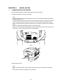
12.1.2 Guaranteed paper
The print image quality specified here is guaranteed with standard paper fed from the
paper tray.
The evaluation is performed with A4 or letter size of paper.
•
FX P paper A4
•
Xerox 4200 DP Letter
•
Xerox Premier 80gsm A4
12.1.3 Paper condition
The paper used is fresh paper immediately after unpacked, which has been left in the
operating environment for 12 hours before unpacking.
12.1.4 Printer condition
The print image quality specified in this section is guaranteed with the printer in normal
condition.
12.1.5 Image quality guaranteed area
The print image quality specified in this section is guaranteed in the guaranteed image
quality area specified in this manual.
12.1.6 Criterion
The print image quality is guaranteed with the Spec. In rate = 95% (γ =90%).
I-18
CHAPTER II
INSTALLATION
CONTENTS
CHAPTER II INSTALLATION...........................................................II-1
1. TRANSPORTING THE PRINTER ................................................................... II-1
2. INSTALLATION PROCEDURE.......................................................................II-2
2.1 Checking the Packaged Items.............................................................................................. II-3
2.2 Removing the Tapes from the Printer................................................................................... II-4
2.3 Removing the Paper Tray Protective Materials .................................................................... II-5
2.4 Mounting the Print Head Cartridge ....................................................................................... II-7
2.5 Preparing the Toner Cartridges .......................................................................................... II-12
2.6 Loading Paper .................................................................................................................... II-13
2.7 Connecting the Power Code............................................................................................... II-17
2.8 Adjusting Color Registrations ............................................................................................. II-18
CHAPTER II
1.
INSTALLATION
TRANSPORTING THE PRINTER
Note the following points when transporting the printer into position.
At least two people should carry the printer.
Note:
Because the printer weighs 34.9kg with the tray and consumables installed, at least two
people should carry it.
To lift the printer, face the front and back of the printer and grip the recessed areas at the
bottom left and right with both hands. Never try to lift the printer by gripping any other
areas. Lifting the printer by gripping other areas can cause the printer to fall, resulting in
injury.
Bend your knees when lifting the printer to avoid back injury.
Never try to lift the printer by gripping the tray cover which protrudes at the lower back of
the printer. It may cause the tray cover to be damaged.
Fig.2-1
Recess
Fig.2-2
Keep the printer level.
Note:
When carrying the printer, keep it level to prevent trays and consumables from falling
out.
Do not tilt it more than 10 degrees in any direction.
II-1
2.
INSTALLATION PROCEDURE
Install the printer as follows:
2.1
Checking the Packaged Items
2.2
Removing the Tapes from the Printer
2.3
Removing the Paper Tray Protective Materials
2.4
Mounting the Print Head Cartridge
2.5
Preparing the Toner Cartridges
2.6
Loading Paper
2.7
Connecting the Power Code
2.8
Adjusting Color Registrations
Note:
The printer has various protective materials for protection from vibrations and shocks
during move. Remove all the protective materials first.
If you purchased a two-tray module, attach the module to the printer first. For the
attachment method, refer to the attached document.
The cardboard box, carrying handle, styrofoam, and protective materials of the printer
package are necessary for the long-distance move of the printer. Be sure not to lose the
packaging materials.
II-2
2.1
Checking the Packaged Items
The printer package contains the items shown below. Before starting installation, make
sure that no items are missing.
Note:
Keep the packaging materials if a future long-distance move of the printer is anticipated.
< Printer >
Fig.2-3
< Print head cartridge >
Fig.2-4
< Power code >
Fig.2-5
Note:
The illustration above shows the 100V power cord.
II-3
2.2
Removing the Tapes from the Printer
When you first remove the printer from its box, there is packing tape to secure the covers
during shipping. Refer to the illustrations below and remove all the packing tape from
the printer.
< Right side >
Fig.2-6
< Left side >
Fig.2-7
< Rear side >
Fig.2-8
II-4
2.3
Removing the Paper Tray Protective Materials
Two spacers are installed in the paper tray to protect it from shock and vibrations during
shipping. Remove the spacers before using the printer. Follow the procedure below to
remove the spacers from the paper tray.
Note:
Keep the spacers in case you need to transport the printer over long distances in the
future.
Fig.2-9
1)
Gently pull out the paper tray until it stops.
Fig.2-10
2)
Hold the tray with both hands, lift the front up slightly and pull it completely out of the
printer.
Note:
Place the tray on a flat surface.
Fig.2-11
II-5
3)
Remove the cardboard spacers from the paper tray.
Note:
Keep the spacers in case you need to transport the printer over long distances in
the future.
Fig.2-12
4)
Holding the paper tray with both hands, align it with the opening in the printer and
gently insert it.
Fig.2-13
5)
Push the paper tray completely back into the printer.
Note:
Do use excessive force on the paper tray. Doing so could damage the paper tray
or the inside of the printer.
Fig.2-14
II-6
2.4
Mounting the Print Head Cartridge
Follow the procedure below to install the print head cartridge.
Fig.2-15
1)
Lift the A button ((1)) and open the front cover ((2)).
Fig.2-16
2)
Open the paper outlet cover.
Fig.2-17
II-7
3)
Open the top of the new print head cartridge box and pull of the top part of the
aluminum package.
Note:
Remove the sheet by working inward from the two notches.
Fig.2-18
4)
Grip the handle on top of the print head cartridge and gently lift it. Place the
cartridge on a flat surface.
Note:
Lift the print head cartridge by the handle. Do not allow the cartridge to touch
anything when removing it from the box.
When setting the print head cartridge, do not shake or tilt them.
Fig.2-19
5)
Remove the polystyrene packing and open the top of the aluminum package from
the left and right.
Fig.2-20
II-8
6)
Take the new print head cartridge out of its package and pull on the longer of the
paired seals horizontally toward you. Verify that there is a circle on the leading edge
of the tape that you pull out. Do this for another three.
Note:
If there is no circle on the leading edge of the tape, you cannot use this print head
cartridge.
Keep the polystyrene packing, aluminum bag and box of the print head cartridge if
a future move of the printer is anticipated.
Check for a circle on the leading end of the tape
Fig.2-21
7)
Remove the tape from the top of the cartridge (1), hold the protective cover on both
sides and remove it from the print head cartridge (2).
Fig.2-22
8)
Grip the handle on top of the print head cartridge and face the flat part towards the
back of the printer.
Flat side faces the rear
Fig.2-23
II-9
9)
With the flat part of the cartridge facing the rear, align the orange rollers on both
sides of the print head cartridge with the slots in front of the arrows on the printer,
and gently lower the cartridge into the printer.
Note:
Lowering the cartridge into the printer without correctly aligning the rollers with the
slots can damage the cartridge.
Do not allow the surface covered with a protective sheet to come into contact with
anything.
Protective sheet
Orange rollers
Fig.2-24
10) Pull the protective sheet on the cartridge straight up to remove it, as illustrated.
Note:
Do not touch the transfer roller (black part). Make sure that nothing touches or
scratches the roller surface. Scratches or oil from your hands on the roller
deteriorates print quality.
Do not touch the transfer roller
Fig.2-25
11) Close the paper outlet cover.
Fig.2-26
II-10
12) Close the front cover.
Fig.2-27
II-11
2.5
Preparing the Toner Cartridges
Follow the procedure below to prepare the toner cartridges for use.
Note:
The toner is harmless but should still be washed off immediately if it comes into contact
with hands or clothing.
1)
Remove the top cover, and then remove the packing sheet covering the toner
cartridges.
Fig.2-28
2)
Pull the toner seal straight up to remove it.
Note:
Pull the toner seal straight up. Pulling the toner seal diagonally may tear the seal.
Fig.2-29
3)
Replace the top cover.
Fig.2-30
II-12
2.6
Loading Paper
Follow the procedure below to load paper into the paper tray.
Fig.2-31
1)
Pull out the paper tray until it stops.
Fig.2-32
2)
Hold the tray with both hands, lift up the front slightly and remove it from the printer.
Note:
Place the tray on a flat surface.
Fig.2-33
II-13
3)
Move the side paper guide out so as to align it with the appropriate paper size mark
(A4 in this example).
Note:
Proper guide position differs between A4 and Letter. Align the side guide to the
size mark corresponding to the paper size that you want to load.
Fig.2-34
4)
Grip the end paper guide with your fingers and gently lift it up. Insert the pins at the
bottom of the guide in the holes corresponding to the paper size that you want to
load (A4 in this example).
Note:
Make sure that the end guide is properly inserted into the holes corresponding to
the appropriate paper size.
Only a small amount of movement of the end paper guide can make automatic
paper size detection impossible. If this occurs, move the end paper guide all the
way to its outermost position again, then realign it with the appropriate paper size
mark.
Fig.2-35
II-14
5)
Align the four corners of the paper stack and insert the paper (print side up) under
the tab.
Note:
Do not use paper that is folded, creased, or heavily warped.
Do not overload the paper tray.
Fig.2-36
6)
Make sure that the side guides are aligned with the edges of the paper.
Note:
Pushing the paper guides too hard against the edges of the paper stack can cause
a paper jam. However, if the paper guide is too loose, the paper may twist as it
feeds through the printer.
Fig.2-37
7)
Hold the paper tray with both hands, align it with the opening in the printer and
gently insert it.
Fig.2-38
II-15
8)
Push the paper tray completely back into the printer.
Note:
Do use excessive force on the paper tray. Doing so could damage the paper tray
or the inside of the printer.
Fig.2-39
Note:
There is an indicator next to the paper tray that tells you how much paper remains
in the tray. Use the meter as a guide to refill the paper tray.
Fig.2-40
II-16
2.7
Connecting the Power Code
Connect the power cable as explained below.
WARNING
Power specifications are listed below. The specifications that apply to your machine
depend on your machine configuration. Connect the power plug only to a properly rated
power outlet. Otherwise, it can cause fire or electric shocks. If in doubt, contact your
Customer Support Center.
- Rated voltage 100V - Rated voltage 110V - Rated voltage 220-240 V
- Rated frequency 50/60Hz - Rated frequency 60Hz - Rated frequency 50/60Hz
Never use multi-plug adaptors to plug multiple power plugs in the same outlet. Be sure
to operate the machine on a sole-use receptacle. Multiple connectors can cause the
outlet to overheat and cause fire.
To prevent fire or electric shocks, follow the instruction below based on your machine
configuration. If in doubt, contact your dealer or authorized Brother service
representative.
- If your machine is a 220-240 V model, there is no need to attach a separate earth line
since the earth connection is incorporated in the power line. Plug it into a properly
rated outlet.
1)
Plug the power cord into the power inlet at the back of the printer. Plug the other
end of the cord into the AC outlet. Connect the earth connection to the ground, if
possible.
Fig.2-41
2)
On the printer's right side, press the side of the power switch marked [ I ] to turn the
printer on.
Note:
The printer motors run for 2 or 3 minutes when you first turn the power on.
Fig.2-42
II-17
2.8
Adjusting Color Registrations
Follow the procedure below to adjust the color registration when first installing the printer
or after moving it to a new location.
1)
Use the control panel to print the color registration adjustment chart.
2)
From the lines to the right of the Y (yellow), M (magenta), and C (cyan) pattern, find
the values of the straightest lines.
Note:
You can also use the densest colors of the grid to find the straightest lines. The colors
printed at the highest density are those next to the straightest lines.
Most straight
Grid pattern
Fig.2-43
3)
Input the values that you found in step 2 into the Y=?, M=? and C=? fields of the
Color registration adjustment.
4)
Press the Set button.
“*” appears and the new color balance chart is printed.
5)
Color registration adjustment is complete when the straightest Y (yellow), M
(magenta) and C (Cyan) lines is next to the '0' line. Close the menu on the control
panel.
Note:
If 0 is not next to the straightest lines, repeat steps 2-5.
II-18
CHAPTER III
STRUCTURE OF
SYSTEM COMPONENTS
CONTENTS
CHAPTER III STRUCTURE OF SYSTEM COMPONENTS ............III-1
1. PRINTING PROCESS ................................................................................... III-1
1.1 Summary of Printing Process .............................................................................................. III-1
1.2 Schematic Diagram for Printing Processes ......................................................................... III-3
1.3 Description of Printing Process Techniques........................................................................ III-4
1.3.1 Charging with electricity ................................................................................................ III-4
1.3.2 Exposure ....................................................................................................................... III-5
1.3.3 Development ................................................................................................................. III-7
1.3.4 Primary transfer (drum -> IDT 1)................................................................................... III-9
1.3.5 Secondary transfer (IDT 1 -> IDT 2) ........................................................................... III-11
1.3.6 Cleaning (IDT 1).......................................................................................................... III-11
1.3.7 Tertiary transfer (IDT 2 - paper) .................................................................................. III-12
1.3.8 Cleaning (IDT 2).......................................................................................................... III-13
1.3.9 Static elimination ......................................................................................................... III-13
1.3.10 Fixing......................................................................................................................... III-14
1.3.11 Cleaning (general) .................................................................................................... III-15
2. FLOW OF PRINT DATA ............................................................................... III-17
2.1 Data Flow........................................................................................................................... III-17
3. DRIVE TRANSMISSION ROUTE................................................................. III-18
3.1 Drive ASSY main ............................................................................................................... III-18
3.2 Drive ASSY DEVE ............................................................................................................. III-19
3.3 Holder Toner Cartridge ASSY (Y, M, C, K) ....................................................................... III-19
3.4 Fuser Drive ASSY.............................................................................................................. III-20
3.5 Motor ASSY DUP............................................................................................................... III-20
3.6 Gear Layout ....................................................................................................................... III-21
4. PAPER TRANSFER..................................................................................... III-22
4.1 Paper Transfer Route (without option) .............................................................................. III-22
4.2 Layout of Paper Transfer Route ........................................................................................ III-23
5. FUNCTIONS OF MAJOR FUNCTIONAL COMPONENTS ........................... III-24
5.1 Paper Cassette .................................................................................................................. III-25
5.1.1 Major functions............................................................................................................ III-25
5.1.2 Reference diagram ..................................................................................................... III-25
5.2 Paper Feeder ..................................................................................................................... III-26
5.2.1 Major functions............................................................................................................ III-26
5.2.2 Reference diagram ..................................................................................................... III-27
5.3 Housing ASSY Retard ....................................................................................................... III-28
5.3.1 Major functions............................................................................................................ III-28
5.3.2 Reference diagram ..................................................................................................... III-28
5.4 Front ASSY In .................................................................................................................... III-29
5.4.1 Major functions............................................................................................................ III-29
5.4.2 Reference diagram ..................................................................................................... III-29
5.5 Chute ASSY Out ................................................................................................................ III-30
5.5.1 Major functions............................................................................................................ III-30
5.5.2 Reference diagram ..................................................................................................... III-31
5.6 Chute ASSY Exit................................................................................................................ III-32
5.6.1 Major functions............................................................................................................ III-32
5.6.2 Reference diagram ..................................................................................................... III-32
5.7 Transfer Roll Cartridge ASSY & Fuser .............................................................................. III-33
5.7.1 Major functions............................................................................................................ III-33
5.7.2 Reference diagram ..................................................................................................... III-34
5.8 Xerographics...................................................................................................................... III-35
5.8.1 Major functions............................................................................................................ III-35
5.8.2 Reference diagram ..................................................................................................... III-36
5.9 Toner Cartridge ASSY ....................................................................................................... III-37
5.9.1 Major functions............................................................................................................ III-37
5.9.2 Reference diagram ..................................................................................................... III-38
5.10 Frame & Drive.................................................................................................................. III-39
5.10.1 Major functions.......................................................................................................... III-39
5.10.2 Reference diagram ................................................................................................... III-39
5.11 Electrical .......................................................................................................................... III-40
5.11.1 Major functions.......................................................................................................... III-40
5.11.2 Reference diagram ................................................................................................... III-41
6. MODES........................................................................................................ III-42
6.1 Print Mode.......................................................................................................................... III-42
6.2 Operation Modes ............................................................................................................... III-42
7. CONTROL ................................................................................................... III-43
7.1 Control of Paper Size......................................................................................................... III-43
7.2 Selective Control on Paper Pick-up Unit ........................................................................... III-43
7.3 Scanner Light Quantity Control ......................................................................................... III-43
7.4 Process Control ................................................................................................................. III-44
7.4.1 Potential control .......................................................................................................... III-44
7.4.2 Toner density control .................................................................................................. III-45
7.4.3 High area coverage mode........................................................................................... III-46
7.4.4 Admix mode ................................................................................................................ III-46
7.4.5 LED light quantity control of holder ASSY CTD.......................................................... III-46
7.5 Color Registration Control ................................................................................................. III-47
7.6 Transfer Roll Cartridge Unit ASSY Control........................................................................ III-48
7.6.1 Detecting the installation of transfer roll cartridge unit ASSY ..................................... III-48
7.6.2 Detecting the life of transfer roll cartridge unit ASSY.................................................. III-48
7.7 Toner Control ..................................................................................................................... III-49
7.7.1 Sensor no toner .......................................................................................................... III-49
7.7.2 Toner presence control ............................................................................................... III-49
7.8 Fuser Control ..................................................................................................................... III-50
7.8.1 Fuser temperature control........................................................................................... III-50
7.8.2 Cool down ................................................................................................................... III-50
7.8.3 Sensor Warm-up ........................................................................................................ III-50
CHAPTER III STRUCTURE OF SYSTEM COMPONENTS
1.
PRINTING PROCESS
1.1
Summary of Printing Process
This printer is a "Full-color laser printer" which applies the principal of an
electrophotographic recording system. The tandem system comprising a drum and
developing unit respectively for each color of yellow, magenta, cyan and black (Y, M, C
and K) places toner image of each color on paper producing full-color prints finally
through 3 intermediate transfer units (IDT 1: 2, IDT 2: 1).
Printing processes of this printer is composed of the basic steps as follows.
1)
Charging with electricity:
Drum surface is charged with electricity.
2)
Exposure:
Image unit is exposed to laser beams.
3)
Development:
Image is developed with toner.
4)
Primary transfer:
Toner image is transferred to the intermediate transfer
unit (IDT 1).
5)
Secondary transfer:
Toner image on the intermediate transfer (IDT 1) is
transferred to the intermediate transfer unit (IDT 2).
6)
Cleaning:
Intermediate transfer unit (IDT 2) is cleaned.
7)
Tertiary transfer:
Four-color finished toner image on the intermediate
transfer unit (IDT 2) is transferred onto the paper.
8)
Cleaning:
Intermediate transfer unit (IDT 2) is cleaned.
9)
Static elimination:
Electric charge of the paper is eliminated.
10)
Fixing:
Toner on the paper is fixed by heat and pressure.
11)
Cleaning:
Remaining toner on the drum and intermediate
transfer units are collected.
III-1
Drum Y
Drum M
Charged
Drum C
Charged
Drum K
Charged
Charged
(1) with
(1) with
(1) with
(1) with
(2) Exposure
(2) Exposure
(2) Exposure
(2) Exposure
(3) Development
(3) Development
(3) Development
(3) Development
electricity
(4)
electricity
electricity
Primary transfer
(Drum
IDT1)
(4) Primary transfer
(Drum
IDT1)
®
Intermediate
transfer unit
( IDT1)
(6)
electricity
®
Intermediate
transfer unit
( IDT1)
Cleaning
( IDT1)
(6)
Cleaning
( IDT1)
(5) Secondary transfer
( IDT1
IDT2)
®
Intermediate
transfer unit
( IDT2)
(8) Cleaning ( IDT2)
(7) Tertiary transfer
( IDT2
Paper)
®
Paper
(11)
(9) Static elimination
(10) Fixing
Fig.3-1
III-2
Cleaning
(general)
Transfer roll
cartridge
1.2
Schematic Diagram for Printing Processes
Outline of printing processes is shown in the figures below.
Toner Cartridge ASSY(Y)
[(3) Development]
Toner Cartridge ASSY(M)
[(3) Development]
: Laser beam
Scanner ASSY
[(2) Exposure]
: Paper transfer
Print Head
Cartridge ASSY
Toner Cartridge ASSY(C)
[(3) Development]
FUSER ASSY
[(10) Fixing]
Toner Cartridge ASSY(K)
[(3) Development]
Detack Saw
[(9) Static elimination]
Transfer Roll
Cartridge ASSY
Transfer Roll Cartridge
[(7) Tertiary transfer]
[(11) Cleaning]
Fig.3-2
Print head cartridge ASSY is integrated major units of printing processes. It is
composed as follows.
RTC
[(1) Changing with electricity]
Refresher
RTC
[(1) Changing with electricity]
Developer(Y)
[(3) Development]
Drum(Y)
Refresher
IDT1
[(4) Primary transfer]
[(5) Secondary transfer]
IDT1 Cleaner
[(6) Cleaning]
Drum(M)
IDT2 Cleaner
[(8) Cleaning]
Developer(M)
[(3) Development]
RTC
[(1) Changing with electricity]
IDT2
[(5) Secondary transfer]
[(7) Tertiary transfer]
Developer(C)
[(3) Development]
IDT1
[(4) Primary transfer]
[(5) Secondary transfer]
Drum(C)
RTC
[(1) Changing with electricity]
Developer(K)
[(3) Development]
IDT1 Cleaner
[(6) Cleaning]
Drum(K)
Refresher
Refresher
Fig.3-3
III-3
1.3
Description of Printing Process Techniques
1.3.1
Charging with electricity
In the charging process, the drum surface rotating at a constant speed is charged
uniformly with negative electricity by discharging of RTC (Rubber Tube Charge: Charged
film).
This process is performed in parallel for yellow, magenta, cyan and black colors.
•
The RTC is kept in contact with the drum and rotates following the rotations of the
drum.
RTC is a conductive roll, receives discharge voltage from HVPS (High Volume
Power Supply) and discharges at minus DC voltage.
•
The drum surface is uniformly and negatively charged with DC bias voltage.
The drum surface is optical conductor (which is insulator in a dark place and
conductor when receiving light) and the drum inside is composed of conductor.
•
The Refresher is a conductive brush, and it receives negative DC voltage from the
HVPS to catch the toner of reverse polarity returned to the drum via IDT. Also, it
removes discharge products.
Refresher
RTC
-
Optical conductor
Conductor
-
HVPS
+
+
+
Drum
Fig.3-4
Drum surface
-V
Electric potential
on drum
0
Fig.3-6
Fig.3-5
III-4
1.3.2
Exposure
In the exposure process, the drum surface charged negatively is scanned by laser
beams to form invisible electrostatic latent image on the drum surface.
This process is performed in parallel for yellow, magenta, cyan and black colors.
•
Laser beams are emitted from the laser diode in the scanner ASSY. By the rotating
polygon mirror, fixed mirror and lens attached to the scanner ASSY of the scanner
ASSY, each color of drum surface is scanned from end to end in the axial direction.
: Laser beams (Y)
: Laser beams (M)
: Laser beams (C)
: Laser beams (K)
Mirror
Mirror
Polygon Mirror
Quad Beam Laser Diode
Mirror
Mirror
Lens
Drum (Y)
Lens
Drum (M)
Drum (C)
Mirror
Drum (K)
Mirror
Mirror
Mirror
Mirror
Fig.3-7
•
The laser beams are emitted based on the print data (image data) from the printer
controller.
When the print data instructs to print pixel points, laser beams are generated and
when the print data instructs not to print, no laser beams are generated. (On the
areas which are developed by toner, the laser beams light up and areas which are
not developed by toner, laser beams go out.) The laser beams emitted on the
drum surface generate a pair (electron <=> hole) in the optical conductive layer.
[Electrons are excited on the conductive zone, causing holes at the valence band.]
Electrons are induced by the electric field, moved toward the inside metallic part
and flow into it. The holes move toward the outer surface of the optical conductive
layer, are combined with the minus charge (electron) on the outer surface again
and decrease negative charge. As a result, on the drum surface where the electric
potential increases, invisible static latent image (print image) is generated.
III-5
Scanner ASSY
: Negative electric charge
: Positive electric charge
Drum surface
(Laser beams)
Optical conductor
Conductor
(Laser beams)
Electrostatic
latent image
Fig.3-9
Drum
Fig.3-8
< Drum concept >
Electric potential
on drum
(Laser beams)
Laser beams
Optical
conductor
-V
0
Conductor
Fig.3-10
Fig.3-11
III-6
1.3.3
Development
In the development process, toner is electrically attached to the invisible statistic latent
image on the drum surface to form visible toner image on the drum.
This process is performed in parallel for yellow, magenta, cyan and black color
respectively.
•
The toner in the toner cartridge is agitated by the agitator in the toner cartridge and
fed into the toner holder. Further, the toner is fed to the developer by the auger in
the toner holder and the auger in the tube that connects the toner holder and the
developer. The agitator and auger are spiral agitating components and they are
driven by the toner motor provided on the rear of toner cartridge. The toner to be
consumed according to the print count is calculated and fed into the developer.
This is called "toner dispensation", which is controlled by two types of control,
"PCDC" and "ADC". For the PCDC and ADC, see 7.4 Process Control in this
chapter.
•
The toner fed into the developer and the carrier in the developer are agitated by the
auger, and supplied to the magnet roll arranged in the vicinity of the drum surface.
The toner and carrier are charged by friction due to the agitation (toner in negative,
carrier in positive), and they are absorbed each other electrically. As the carrier is a
magnetic substance, it is attracted to the magnet roll having a magnetic force and a
homogeneous layer is formed by the trimmer rod and the paddle.
•
The magnet roll is covered by a thin semi-conductive sleeve over the surface. DB
(Developing Bias) voltage is supplied to this semiconductor sleeve from HVPS. DB
voltage is negative DC voltage combined with AC voltage. The magnet roll is kept
at constant negative voltage against the optical conducting layer of the drum by DC
voltage. Therefore, at the area on the drum surface where the negative electric
charge does not decrease, potential is lower than the magnet roll, while the
potential is higher than the magnet roll at the area where the negative charge on the
drum surface decreases. The AC voltage shakes the developer on the magnet roll
surface pressing the toner to fly to the drum.
Thus, the toner charged negatively is attracted only by the area where the minus
charge has decreased on the drum surface from the magnet roll (static latent
image) and the toner image is formed on the drum.
When the toner is attached, minus charge at that portion increases, potential
decreases, and force to attract the toner decreases.
III-7
Toner Cartridge ASSY
- : Negative electric charge
+ : Positive electric charge
Agitator
: Toner
: Carrier
Auger
Trimmer Rod
Magnet Roll
Paddle
-
Auger
-
Auger
-
+
+
Drum
+
-
+
-
HVPS
Fig.3-12
Electric potention
on drum
Dram surface
-V
Developing
bias
Toner image
0
Fig.3-13
Fig.3-14
III-8
1.3.4
Primary transfer (drum -> IDT 1)
In the primary transfer process, toner image formed on the drum surface is transferred
onto the surface of the IDT 1 (Intermediate Drum Transfer 1: intermediate transfer roll 1).
Two IDT 1 are provided: yellow and magenta, and cyan and black are respectively
transferred to their IDT 1.
•
IDT 1 is a conductive roll and receives supply of high positive voltage from HVPS.
The toner image (negatively charged) on the drum is attracted to the IDT1 positively
charged, and transferred from the drum to the IDT1 surface.
At this time, electric charge of the drum surface is neutralized by the IDT1.
- : Negative electric charge
+ : Positive electric charge
Drum surface
: Toner
Drum (Y)
- -
Fig.3-16
+
+
+
IDT1
+
+
+
+
+
-
Drum (M)
+ +
+ +
- -
Drum (C)
- -
+
+
+
+
+
+
+
-
Drum (K)
+
+ +
IDT1
HVPS
+ +
- -
Fig.3-15
III-9
Drum surface
(Yellow toner image)
IDT1 surface
Yellow
toner image
Magenta
toner image
Drum surface
(Magenta toner image)
Drum surface
(Cyan toner image)
IDT1 surface
Cyan
toner image
Drum surface
Black
toner image
(Black toner image)
Fig.3-17
III-10
1.3.5
Secondary transfer (IDT 1 -> IDT 2)
In the secondary transfer process, the toner image formed on the IDT 1 surface is
transferred onto the surface of the IDT 2 (Intermediate Drum Transfer 1: intermediate
transfer roll 2).
Two color toner image transferred onto the 2 IDT 1 is transferred to the IDT 2. Thus, 4
color toner image are compiled on the IDT 2 as finished toner image.
•
1.3.6
IDT 2 is a conductive roll and receives supply of positive high voltage from HVPS.
Both the IDT 1 and IDT 2 are positively charged. Voltage is higher on the IDT 2 and
toner image is attracted to the IDT 2 surface and transferred onto the IDT 2.
Cleaning (IDT 1)
In the cleaning process (IDT 1), toner remaining on the IDT 1 after the toner image is
transferred to the IDT 2 is temporarily stored in the IDT 1 cleaner.
•
The IDT 1 cleaner receives positive high voltage from the HVPS with a conductive
roll brush.
The IDT 1 cleaner is placed in contact with the IDT 1 at the position through which it
passes after the toner image having been transferred from the drum is transferred
to the IDT 2. Toner remaining on the IDT 1 is electrically scraped and stored.
The toner stored is collected upon completion of printing or at the time of cleaning
cycle. (Refer to1.3.11 Cleaning (general).)
+ : Positive electric charge
: Toner
IDT1
IDT1 Cleaner
+
+
+
+
+
+
+
+
+
+
+
+
+
IDT2
+
+
+
+ +
++ + +
+ +
+
+
+
IDT1
HVPS
HVPS
IDT1 Cleaner
Fig.3-18
III-11
IDT1 surface
Yellow
toner image
Magenta
toner image
IDT2 surface
Yellow
toner image
Magenta
toner image
Cyan
toner image
IDT1 surface
Black
toner image
Cyan
toner image
Black
toner image
Fig.3-19
1.3.7
Tertiary transfer (IDT 2 - paper)
In the tertiary transfer process, finished toner image formed on the IDT 2 surface is
transferred onto the paper under the voltage supplied to the transfer roll cartridge.
•
Transfer roll cartridge is composed in the transfer roll cartridge ASSY.
Transfer roll cartridge is a conductive roll and receives positive high current from
HVPS.
When paper passes through between IDT2 and transfer roll cartridge, plus potential
is given to the back side of the paper so that the toner on the IDT 2 is transferred
onto the paper. At this time, potential on the transfer roll cartridge is higher than
that on the IDT 2.
III-12
1.3.8
Cleaning (IDT 2)
In the cleaning process, toner remaining on the IDT 2 after the toner image is transferred
onto the paper is temporarily held at the IDT 2 cleaner.
•
1.3.9
The IDT 2 cleaner is a conductive roll brush and receives positive high voltage from
HVPS.
The IDT 2 cleaner is placed in contact with the IDT 2 at a position through which it
passes after the toner image having been transferred from IDT 1 is transferred onto
the paper. Remaining toner on the IDT 2 is electrically scraped and held at the IDT
2 cleaner.
The toner held is collected upon completion of printing or at the cleaning cycle.
(Refer to 1.3.11 Cleaning (general).)
Static elimination
In the static elimination process, negative DC voltage is given to the back side of the
paper from the detack saw (static elimination board) to neutralize and eliminate the
charge of paper.
•
The detack saw receives high voltage from HVPS.
The positive charge caused in the tertiary transfer process generates image quality
troubles by. scattering toner. Static electricity of the paper is eliminated by
discharge of the detack saw preventing those image quality troubles.
- : Negative electric charge
+ : Positive electric charge
IDT2 Cleaner
: Toner
IDT2
+
+
+
+ + +
+
+
+ + - Detack Saw
+
+
Transfer Roll
Cartridge
HVPS
Paper
HVPS
Fig.3-20
III-13
1.3.10 Fixing
In the fixing process, toner is fixed on the paper by heat and pressure.
•
Finished toner image transferred from the belt is easily broken only by touching it
with fingers. The toner image is fixed on the paper with the fuser ASSY (fixing unit).
The toner melts by heat of the heat roll with the heater lamp as the heat source and
is deposited on the paper under pressure given by the belt opposed against the
heat roll.
Paper
Spring Nip
Fixed toner
Nip Head
Belt
Heat Roll
Felt
Heater Lamp
Frame Belt
Sheet
Not fixed toner
Pad
Fig.3-21
III-14
1.3.11 Cleaning (general)
In the cleaning (general) process, toner stored in the IDT 1 cleaner and IDT 2 cleaner
after the finished toner image is transferred onto the paper and the toner remaining on
the transfer roll cartridge are removed.
•
The toner not completely transferred in the "secondary transfer" and "tertiary
transfer" processes is held temporarily in the IDT1 cleaner and IDT2 cleaner. Also,
the toner of which polarity is reversed and returned to the drum is held in the
refresher. Further, the toner that passes the refresher may stick to the RTC.
These toners are cleaned at the completion of the printing. The recovery method is
different between the toner held in the IDT1 cleaner and IDT2 cleaner and the toner
held in the refresher and RTC.
1) IDT1 cleaner and IDT2 cleaner
High voltage equivalent to the voltage at the printing transfer is applied to the IDT1,
IDT2, and transfer roll cartridge. The toner (negative polarity) remaining in the IDT1
cleaner and IDT2 cleaner are moved to the IDT1 and IDT2 electrically by
transforming the IDT1 cleaner and IDT2 cleaner to 0V. Then, in the same manner
as in the printing transfer, the residual toner is collected to the transfer roll cartridge
surface by potential difference between IDT1, IDT2, and transfer roll cartridge.
+
+ : Positive electric charge
: Toner
+
+
IDT1
+
+
+
+
+
IDT2 Cleaner
+
+
+
+
IDT2
+
+
IDT1 Cleaner
+
+
+
+
+ Transfer
Roll
+
IDT1
+
+
+
+
Cartridge
+
+
+
+
+
+
HVPS
+
HVPS
IDT1 Cleaner
Fig.3-22
III-15
Scraper
HVPS
2) Refresher and RTC
High voltage of the polarity (negative) reverse to that at the printing transfer is
applied to the IDT1, IDT2, and transfer roll cartridge. At this time, the drum surface
is charged negatively by negative voltage of the IDT1. The toner (positive polarity)
remaining in the Refresher and RTC are move to the drum electrically by
transforming the Refresher and RTC to 0V. Then, in the same manner as in the
printing transfer, the residual toner is collected to the transfer roll cartridge surface
by potential difference between IDT1, IDT2, and transfer roll cartridge.
•
Toner attached to the surface of transfer roll cartridge is scraped off with the
transfer roll cartridge cleaner which is in contact with the transfer roll cartridge and
collected into the collection space in the transfer roll cartridge unit ASSY.
Refresher
RTC
-
: Negative electric charge
: Toner
-
Drum (Y)
- - -
IDT1
Refresher
-
RTC
-
-
Drum (M)
-
-
-
Refresher
-
-
IDT2
-
RTC
-
-
-
-
Refresher
-
RTC
-
-
-
-
Drum (C)
IDT1
-
-
Transfer
Roll
Cartridge
-
-
-
Drum (K)
HVPS
-
-
HVPS
-
Fig.3-23
III-16
Scraper
HVPS
2.
FLOW OF PRINT DATA
2.1
Data Flow
Print data (electric signal) from the printer controller flows as shown below to turn to the
print image finally.
Host (electric signal)
Printer controller (electric signal)
MCU HL-4200 (electric signal)
Scanner ASSY (laser beams)
Electrostatic latent on drum
(invisible image)
Toner image on drum
Toner image on intermediate transfer unit
(IDT1)
Toner image on intermediate transfer unit
(IDT2)
Toner image on paper
Print image on paper
Fig.3-24
III-17
3.
DRIVE TRANSMISSION ROUTE
3.1
Drive ASSY main
Rotary power of the drive ASSY main is transmitted through the route below.
MAIN DRIVE ASSY
GEAR IDLER IN
Regi.Clutch
CLUTCH ASSY TURN
GEAR IDLLER
ROLL ASSY TURN
GEAR IDLLER FEED
Regi.Roll
CHUTE REGI ASSY
GEAR FEED H1
GEAR FEED1
ROLL ASSY FEED
PAPER FEEDER
CLUTCH TURN
GEAR MSI
IDT2
ROLL TURN
ROLL ASSY FEED
IDT1 (2)
HOUSING ASSY RETARD
CHUTE ASSY OUT
Drum (4)
PRINT HEAD
CARTRIDGE ASSY
TRANSFER ROLL
CARTRIDGE ASSY
Fig.3-25
III-18
3.2
Drive ASSY DEVE
The rotary power of the Drive ASSY DEVE drives the developers of 4 colors in the print
head cartridge ASSY.
DEVE DRIVE ASSY
Developer (M)
Developer (Y)
Developer (C)
Developer (K)
PRINT HEAD CARTRIDGE ASSY
Fig.3-26
3.3
Holder Toner Cartridge ASSY (Y, M, C, K)
Rotary power of the toner motor in the holder toner cartridge ASSY drives the agitator in
the toner cartridge ASSY (to supply toner from the toner cartridge ASSY to holder toner
cartridge ASSY) and auger in the holder toner cartridge ASSY (to supply toner to
developer in the print head cartridge ASSY).
Four holder toner cartridge ASSY, Y, M, C and K, operate respectively in the same way.
Toner Motor
Gear
Auger
Auger
Gear
Film
Agitator
HOLDER TONER CARTRIDGE ASSY
Fig.3-27
III-19
TONER CARTRIDGE ASSY
3.4
Fuser Drive ASSY
Rotary power of the fuser drive ASSY drives the fuser ASSY.
FUSER DRIVE ASSY
Heat Roll
Gear Exit
Roll Assy Exit
FUSER ASSY
Fig.3-28
3.5
Motor ASSY DUP
Rotary power of the motor ASSY DUP is transmitted through the route below.
MOTOR ASSY DUP
GEAR 48
GEAR 48
GEAR 40/42
GEAR 40/42
GEAR ROLL
GEAR ROLL
ROLL EXIT
ROLL MID
GEAR42
CHUTE ASSY EXIT
GEAR 30
ROLL DUP
CHUTE ASSY OUT
Fig.3-29
III-20
3.6
Gear Layout
PRINT HEAD CARTRIDGE ASSY
CHUTE ASSY OUT
TRANSFER ROLL
CARTRIDGE ASSY
REGI CLUTCH
CHUTE REGI
ASSY
MAIN DRIVE ASSY
CLUTCH ASSY TURN
GEAR MSI
GEAR IDLER FEED
HOUSING ASSY RETARD
CLUTCH TURN
GEAR IDLER IN
GEAR FEED1
GEAR IDLER
GEAR FEED H1
FRONT
PAPER FEEDER (PICK UP ASSY)
Fig.3-30
GEAR ROLL
GEAR ROLL
MOTOR ASSY DUP
GEAR 48
GEAR 40/42
GEAR 40/42
GEAR 48
GEAR 42
CHUTE ASSY EXIT
GEAR 30
CHUTE ASSY OUT
FRONT
Fig.3-31
III-21
4.
PAPER TRANSFER
4.1
Paper Transfer Route (without option)
Paper feed from paper tray (Tray 1)
Paper feed from MSI
Paper feed by "ROLL ASSY FEED (Pick up ASSY)"
Paper feed by "ROLL ASSY FEED (MSI)"
and "ROLL ASSY RETARD"
Paper feed by "ROLL ASSY (Paper Cassette)" in
cassette and "ROLL ASSY (Pick up ASSY)" in feeder
Paper transfer by "ROLL TURN"
and "ROLL PINCH TURN"
Paper transfer by "ROLL ASSY TURN"
and "CHUTE ASSY TURN"
Paper transfer by "Regi Roll" and "Metal Roll" of CHUTE ASSY REGI
Paper transfer by "IDT2" of PRINT HEAD CARTRIDGE ASSY and
"TRANSFER ROLL CARTRIDGE" of TRANSFER ROLL CARTRIDGE UNIT ASSY
Paper transfer by "Heat Roll" and "Fuser Belt" of FUSER ASSY
Paper transfer by "ROLL ASSY EXIT" and "Pinch Roll" of FUSER ASSY
Paper transfer by "ROLL MID" of CHUTE ASSY EXIT and "ROLL PINCH" OF CHUTE ASSY OUT
Paper transfer by "ROLL EXIT" of CHUTE ASSY EXIT and "ROLL PINCH EXIT" of CHUTE ASSY OUT
Print output
Paper transfer to duplex path by reversing
"ROLL EXIT" and "ROLL MID"
Paper transfer by "ROLL DUP"
and "ROLL PINCH DUP"
Fig.3-32
III-22
4.2
Layout of Paper Transfer Route
: Laser beam
: Paper transfer
: Paper sensors
ROLL EXIT
ROLL PINCH EXIT
ROLL MID
ROLL PINCH
Heat Roll
Pinch Roll
IDT2
ROLL ASSY EXIT
Fuser Belt
ROLL DUP
ROLL PINCH DUP
Transfer Roll Cartridge
Metal Roll
Regi Roll
ROLL ASSY FEED (MSI)
ROLL ASSY RETARD
ROLL PINCH TURN
ROLL TURN
CHUTE ASSY TURN
ROLL ASSY FEED
(PICK UP ASSY)
ROLL ASSY TURN
(PICK UP ASSY)
ROLL ASSY(PICK UP ASSY)
ROLL ASSY (Paper Cassette)
Fig.3-33
III-23
5.
FUNCTIONS OF MAJOR FUNCTIONAL COMPONENTS
Major functional components comprising the printer are described below referring to their
illustrations.
Those components are classified into the following blocks based on the configuration of
the printer.
•
Paper Cassette
•
Paper Feeder
•
Housing ASSY Retard
•
Front ASSY In
•
Chute ASSY Out
•
Chute ASSY Exit
•
Transfer Roll Cartridge ASSY & Fuser
•
Xerographics
•
Toner Cartridge ASSY
•
Frame & Drive
•
Electrical
III-24
5.1
Paper Cassette
5.1.1
Major functions
5.1.2
•
Side Guide
The side guide can move at right angle to the paper transfer direction to align the
paper width.
•
End Guide
The end guide can move in the paper transfer direction to determine the paper size.
The ON/OFF of switch ASSY size (see 5.2 Paper Feeder) varies according to the end
guide position to detect the paper size.
•
Roll ASSY (Cassette)
The roll ASSY (Cassette) and the roll ASSY (pick up ASSY T1) (see 5.2 Paper
Feeder) pinch the paper to feed.
Reference diagram
End Guide
Side Guide
ROLL ASSY(Paper Cassette)
Side Guide
Fig.3-34
III-25
5.2
Paper Feeder
5.2.1
Major functions
•
Switch ASSY size
Switch ASSY size detects paper size and existence or non existence of the paper tray.
•
Sensor photo (No paper sensor)
Detects existence or non existence of paper in the paper tray based on the position of
actuator no paper. (No paper: Sensor beam is intercepted)
•
Sensor photo (Low paper sensor)
The actuator lowers according to how much paper remains in the paper tray. When
the actuator lowers to certain extent, it intercepts the sensor beam to detect low paper
quantity.
As the actuator position can be seen from the front side of paper tray, you can confirm
approximate residual paper quantity.
•
Solenoid feed
Controls operation (rotation/stop) of roll ASSY feed by controlling the rotations of the
gear feed.
•
Clutch ASSY turn
Transmits the drive from the drive ASSY main to roll ASSY turn.
•
Roll ASSY feed (Pick up ASSY)
When the solenoid feed operates, the gear feed and gear idler feed are engaged by
the force of the spring feed. Under the drive from the drive ASSY main, the roll ASSY
feed starts rotating and the roll ASSY (pickup ASSY T1) sends paper.
After having rotated one turn, the gear feed and gear idler feed are disengaged at the
notch of the gear feed, no drive is transmitted any more, and the roll ASSY feed stops
rotating. Thus sheets of paper is sent out one by one.
•
Roll ASSY turn
The roll ASSY turn rotates by the drive from the drive ASSY main through the clutch
ASSY turn to feed the paper from the paper tray to chute REGI (REGI roll) ("refer to
5.8 Xerographics").
•
Sensor HUM TEMP
Detects temperature and humidity in the printer.
The printer corrects the charging voltage, the voltage supplied to the transfer rolls, and
the developing bias based on the detected temperature and humidity.
III-26
5.2.2
Reference diagram
SENSOR PHOTO(No Paper Sensor)
ROLL ASSY FEED(PICK UP ASSY)
SENSOR HUM TEMP
CLUTCH ASSY TURN
SWITCH ASSY SIZE
GEAR FEED
SPRING FEED
GEAR IDLER FEED
ROLL ASSY TURN
SOLENOID FEED
ROLL ASSY(PICK UP ASSY)
SENSOR PHOTO(Low Paper Sensor)
Fig.3-35
III-27
5.3
Housing ASSY Retard
5.3.1
Major functions
5.3.2
•
Clutch turn (MSI)
Transmits the drive from the drive ASSY main to the roll turn.
•
Roll turn
The roll turn is rotated by the drive from the drive ASSY main through the clutch turn
(MSI) to feed the paper from the manual feed tray to the chute REGI (REGI roll) (refer
to "5.8 Xerographics").
Reference diagram
ROLL TURN
CLUTCH TURN ( MSI )
Fig.3-36
III-28
5.4
Front ASSY In
5.4.1
Major functions
5.4.2
•
Holder ASSY CTD
Reads the density of the toner image prepared on the surface of transfer roll cartridge
in the transfer roll cartridge unit ASSY (refer to "5.7 Transfer Roll Cartridge ASSY &
Fuser") and feeds it back to the process control (refer to "7.4 Process Control").
•
Sensor TNR full
Detects that the toner collect space in the transfer roll cartridge unit ASSY (refer to
"5.7 Transfer Roll Cartridge ASSY & Fuser") has become full of waste toner to be
collected.
•
Fuser drive ASSY
Supplies the drive to the fuser ASSY (refer to "5.7 Transfer Roll Cartridge ASSY &
Fuser").
Reference diagram
HOLDER ASSY CTD
FUSER ASSY
SENSOR TNR FULL
FUSER DRIVE ASSY
Fig.3-37
III-29
5.5
Chute ASSY Out
5.5.1
Major functions
•
Sensor photo (Full stack sensor)
Detects that the prints discharged onto the top cover have accumulated more than
specified number of sheets based on the change of position of the actuator.
(Full stack: Sensor beam is received)
•
Sensor photo (DUP jam sensor)
Detects that paper has reached and passed through the roll DUP based on the
change of position of the actuator.
(Paper present: Sensor beam is received)
•
Sensor photo (MSI no paper sensor)
Detects existence or non existence of paper on the manual feed tray based on the
change of position of the actuator.
(No paper: Sensor beam is intercepted)
•
Solenoid feed MSI
Controls the operation (rotation/stop) of roll ASSY feed by controlling the rotations of
the gear MSI.
•
Roll ASSY feed
When the solenoid feed MSI operates, the gear MSI and gear idler are engaged by the
force of the spring SOL, the roll ASSY feed starts rotating under the drive from the
drive ASSY main, and feeds paper from the manual feed tray.
After having rotated one turn, the gear MSI and gear idler are disengaged at the notch
of the gear MSI, drive is not transmitted any more, and the roll ASSY feed stops
rotating. Thus sheets of paper are fed one by one.
•
Roll DUP
The roll DUP rotates under the drive from the motor ASSY DUP and feeds paper
printed on simplex returned from the chute ASSY exit to the roll turn (refer to "5.3
Housing ASSY Retard)".
III-30
5.5.2
Reference diagram
SENSOR PHOTO(Full Stack Sensor)
SENSOR PHOTO(DUP Jam Sensor)
ROLL DUP
Gear Idier (DRIVE ASSY MAIN)
GEAR MSI
ROLL ASSY FEED (MSI)
SENSOR PHOTO(MSI No Paper Sensor)
SOLENOID FEED MSI
Fig.3-38
III-31
5.6
Chute ASSY Exit
5.6.1
Major functions
5.6.2
•
Motor ASSY DUP
Supplies drive to the roll exist, roll MID, and roll DUP.
•
Roll exit
The roll exit rotates under the drive from the motor ASSY DUP, and feeds fixed prints
onto the top cover. It reverses in the duplex document mode and feeds the prints after
fixed on simplex in the REGI direction.
•
Roll MID
The roll MID rotates under the drive from the motor ASSY DUP, and feeds fixed prints
onto the top cover. It reverses in the duplex document mode and feeds the prints after
fixed on simplex in the REGI direction.
Reference diagram
ROLL MID
MOTOR ASSY DUP
ROLL EXIT
Fig.3-39
III-32
5.7
Transfer Roll Cartridge ASSY & Fuser
5.7.1
Major functions
•
Fuser ASSY
The fuser ASSY fixes toner which was transferred onto the paper but not fixed by the
heat and pressure and feeds paper before and after being fixed.
The fuser ASSY mainly consists of the following parts:
• Heat roll
• Belt unit
• Heater lamp
• Roll ASSY exit
• Thermostat
• Exit sensor
• Temp sensor
• Fuser EEPROM
• Fuser NCS
•
Exit sensor
Detects passage of print after fixed based on the change of position of the
actuator.
•
Transfer roll cartridge unit ASSY
The transfer roll cartridge unit ASSY consists of a transfer roll cartridge and a waste
toner recovery system.
The transfer roll cartridge is opposed to the IDT 2 in the print head cartridge ASSY and
transfer the toner image on the IDT 2 onto the paper.
•
Fan fuser
The fan fuser exhausts the heat of fuser ASSY to prevent inside temperature from
overheating.
III-33
5.7.2
Reference diagram
FUSER ASSY
Exit Sensor
FAN FUSER
Transfer Roll Cartridge ASSY
Fig.3-40
III-34
5.8
Xerographics
5.8.1
Major functions
•
•
Scanner ASSY
Scanner ASSY (raster output scanner assembly) is an exposure unit to generate laser
beams to form electrostatic latent image on the drum surface.
In this manual, the scanner ASSY is referred to as scanner ASSY.
The scanner ASSY mainly consists of the following parts:
• LD ASSY
• Lens
• Scanner ASSY
• Mirror
• SOS PWB
• Window
Print head cartridge ASSY
Print head cartridge ASSY carries out a series of operation in the print process such
as charging, developing and transfer.
Print head cartridge ASSY mainly consists of the following parts.
• Drum (Y)
• Developer (Y)
• Drum (M)
• Developer (M)
• Drum (C)
• Developer (C)
• Drum (K)
• Developer (K)
• RTC (Y)
• Refresher (Y)
• RTC (M)
• Refresher (M)
• RTC (C)
• Refresher (C)
• RTC (K)
• Refresher (K)
• IDT 1 (2)
• IDT 2
• IDT 1 cleaner (2)
• IDT 2 Cleaner
•
Chute REGI (REGI clutch)
The chute REGI is composed of the REGI clutch, REGI roll and metal roll.
Drive from the drive ASSY main is transmitted to the REGI roll through the REGI
clutch. Feeds paper from the tray, MSI and duplex path in the print head cartridge
ASSY direction. When the paper tip reaches the chute REGI, the chute REGI has the
paper make a loop until the REGI roll starts rotating and correct the skew (feeding the
paper in inclined condition) of the tip of the paper.
•
Sensor photo (REGI sensor)
Detects that the paper tip has reached the chute REGI.
(Paper present: Beam is received)
•
OHP sensor
As plain paper scatters the radiated light, the OHP sensor can capture the reflected
light to detect the paper. The OHP paper scarcely scatters the radiated light, and
therefore the OHP sensor cannot capture the reflected light. Thus, whether the paper
fed from MSI is plain paper or OHP paper is judged.
III-35
5.8.2
Reference diagram
Scanner ASSY
Print Head Cartridge ASSY
OHP SENSOR
SENSOR PHOTO(Regi Sensor)
CHUTE REGI(Regi Clutch)
Fig.3-41
III-36
5.9
Toner Cartridge ASSY
5.9.1
Major functions
•
PWBA CRUM READER
The PWB consists of each color toner bottle switch and CRUM.
Toner bottle switch:
Detects whether toner cartridge (toner bottle) of each color is installed or not.
CRUM:
Printer specific information is stored.
•
Sensor no toner (Y)
•
Sensor no toner (M)
•
Sensor no toner (C)
•
Sensor no toner (K)
Detects residual toner of each color.
•
Holder Toner Cartridge ASSY (1) (Toner motor: Y)
•
Holder Toner Cartridge ASSY (2) (Toner motor: M)
•
Holder Toner Cartridge ASSY (3) (Toner motor: C)
•
Holder Toner Cartridge ASSY (4) (Toner motor: K)
The toner motor incorporated in the holder toner cartridge ASSY of each color supplies
the drive to the agitator in the toner cartridge ASSY of each color and to auger in the
holder toner cartridge ASSY and supplies toner to the developer incorporated in the print
head cartridge ASSY.
•
Toner Cartridge ASSY (Y)
•
Toner Cartridge ASSY (M)
•
Toner Cartridge ASSY (C)
•
Toner Cartridge ASSY (K)
Toner bottle containing tone of each color.
•
PWBA EEPROM
Printer specific information is stored.
•
S-HVPS
Supplies high voltage to perform the “tertiary transfer” and “static elimination” of the print
process to the following components.
• Transfer Roll Cartridge in the Transfer
Roll Cartridge unit ASSY.
• Detack saw in the Transfer Roll Cartridge
unit ASSY.
III-37
5.9.2
Reference diagram
PWBA CRUM READER
TONER CARTRIDGE ASSY (Y)
TONER CARTRIDGE ASSY (M)
S-HVPS
TONER CARTRIDGE ASSY (C)
TONER CARTRIDGE ASSY (K)
PWBA EEPROM
HOLDER ASSY TONER HBN(K)
(Toner Motor : K)
HOLDER ASSY TONER HBN(C)
(Toner Motor : C)
SENSOR NO TONER(Y)
SENSOR NO TONER(M)
HOLDER ASSY TONER HBN(M)
(Toner Motor : M)
SENSOR NO TONER(C)
SENSOR NO TONER(K)
HOLDER ASSY TONER HBN(Y)
(Toner Motor : Y)
Fig.3-42
III-38
5.10
Frame & Drive
5.10.1 Major functions
•
Drive ASSY main
Supplies the drive to parts as follows.
• Paper feeder
• Housing ASSY retard
• Chute ASSY out (MSI position)
• Chute REGI
• Print Head Cartridge ASSY (IDT 2, IDT 1,
Drum)
• Transfer Roll Cartridge unit ASSY
•
Drive ASSY DEVE
Supplies the drive to parts as follows.
• Print Head Cartridge ASSY (Developer)
5.10.2 Reference diagram
Fig.3-43
III-39
5.11
Electrical
5.11.1 Major functions
•
Fan Rear
Discharges heat out of the printer to prevent too high temperature in the printer.
•
Harness ASSY AC SW
Composed of the main switch and inlet and controls supply of AC power from the power
source to LVPS.
•
LVPS
The LVPS is provided with two types, 100/120V and 230V.
Supplies AC power from the power source to the fuser ASSY heater and generates and
supplies stable low voltage DC power used for the logic circuit, etc.
LVPS contains control circuit for the heater of the fuser ASSY, in addition to the power
circuit.
•
MCU HL-4200
Controls printing operation based on the communication with the print controller and
information from the sensor/switch. Incorporates functions of HVPS.
Major functions are as follows:
• Communication with the printer controller.
• Receive of information from the sensors or switches.
• Control of Scanner ASSY
Supplies high voltage to parts in the print head cartridge ASSY to perform charging,
development, primary transfer and secondary transfer of the print process to the
following parts in the ASSY.
• RTC
• IDT 2
• Refresher
• IDT 1 Cleaner
• Developer
• IDT 2 Cleaner
• IDT 1
•
PWBA HBN DRV
Controls parts of motor and so on by the signal from the MCU HL-4200 and sends
information from the sensors and switches to the MCU HL-4200. The power from the
LVPS is supplied to the MCU HL-4200 through this PWB. Also, the interlock switch is
mounted on this PWB.
Major functions are as follows:
• Recive of information from the sensors or switches.
• Control of toner motor in drive ASSY main, drive ASSY DEVE, fuser drive
ASSY, motor ASSY DUP, and holder toner cartridge ASSY.
• Distributing low voltage DC power outputted from LVPS to each component.
• Cutting off the 24VDC circuit by the interlock switch
•
Controller board
Receives data from the host, prints and controls the whole printer.
•
Font Card
Records font information of printer.
III-40
•
HDD
Optional HDD is used for two uses described below.
The space used for each function is divided into partitions by the fixed ratio. The space
doesn't have relation each other.
The ratio cannot be changed.
*Breakdown:
(1) Job Log: 2MB
(2) PostScript file system: 512MB
(It would be the half of the whole HDD if the capacity of HDD is less than 1GB.)
(3) Memory sort on HDD: rest of capacity
* It can be confirmed on the printer setting list.
1. Memory sort on HDD
Printing is executed by copying pages per job.
(For example, in case of 5 pages document, it prints in order as 1,2,3,4,5, 1,2,3,4,5...)
Characteristic:
It starts to print the first set and store the job to spool area simultaneously when only
the printed data of the first set was received from a printer driver. The printing speed
of second set and later can be faster by using the stored data.
Therefore, the burden of a driver and communication traffic between a host and a
printer can be reduced, and the entire throughput can be enhanced.
High speed electron sort implemented HDD causes a printer error and cancels the
rest of printing if the data which spools to the HDD exceeds the capacity of the HDD.
2. PostScript file system
The file system function of PostScript can be used.
Generally, it is used to memorize initialization job and Type1 font.
5.11.2 Reference diagram
HDD
CONTROLLER BOARD
MCU HL-4200
PWBA HBN DRV
FAN REAR
LVPS
HARNESS ASSY AC SW
FONT CARD
Fig.3-44
III-41
6.
MODES
6.1
Print Mode
The printer has four modes, Standard mode, Fine mode, High gloss mode, and Super
high gloss mode. Modes are switched over under the instruction from the controller.
1. Standard mode:
2. Fine mode:
3. High gloss mode:
Used for printing with resolution 600dpi
Process direction resolution 1200dpi mode
Thick paper, special paper, and high glossed plain paper
Relation between the resolution, process speed, print mode and paper mode is shown in
the table below.
Paper mode
Plain
paper
Thick
paper
*1
Special
paper *2
Print mode
Standard
mode
Fine mode
High gloss
mode
Fine mode
High gloss
mode
Resolution/Process speed
600dpi
1200dpi
Simplex
Duplex
Simplex
Duplex
Full speed
Full speed
--
--
--
--
Half speed
Half speed
Half speed
Half speed
--
--
--
--
Half speed
Half speed
Half speed
Half speed
--
--
*1: Thick paper-L,Thick paper-H
*2: Label-L , Label-H, OHP, Envelope, Postcard
6.2
Operation Modes
For the operation of the printer, the following seven modes are provided.
•
DIAG test mode
The printer is ready for receiving diagnostic commands, or the printer diagnostic function
is operating.
•
Wait mode
The printer is under the adjustment of print quality.
•
Ready mode
The printer is ready for printing.
•
Printing mode
The printer is under printing.
III-42
•
Error mode
Any error was detected in the printer.
•
Initiglizing mode
New parts have been just set to the printer (initializing with a new PHD).
•
Checking Unit mode
Printer is under checking consumable units.
7.
CONTROL
7.1
Control of Paper Size
"ON/OFF of paper size switch of switch ASSY size " and "Diag tool indication data" are
shown in the table below.
Note:
Paper size switches are indicated as SW1, SW2, and SW3 from the above one.
Paper size switch
Diag
Paper size
indication data
SW1
SW2
SW3
LEGAL14"
ON
ON
ON
00
LEGAL13"
ON
ON
OFF
01
EXECUTIVE
ON
OFF
ON
02
B5
ON
OFF
OFF
03
A4
OFF
ON
ON
04
LETTER
OFF
OFF
ON
06
A5
OFF
ON
OFF
05
No cassette
OFF
OFF
OFF
07
7.2
Selective Control on Paper Pick-up Unit
When not controlled by the printer controller, paper pick-up unit selected at the time of
turning ON are as follows.
Note:
The paper feeder by the paper tray under the printer is called "Tray 1", and the first tray
and the second tray in optional tray unit are called "Tray 2" and "Tray 3" respectively.
7.3
Scanner Light Quantity Control
The image data are entered to the laser diodes in the scanner ASSY as electric signals
(data are expressed with high and low voltage values), and the laser diodes convert the
image data from electric signals to optical signals (data are expressed with blinking laser
beams).
Variations in light quantity of laser beams or variations in optical system (such as lenses)
or drum sensitivity cannot attain proper electrostatic image, and accordingly the laser
diodes monitor the light quantity of laser beams to control the light quantity so as to
attain stable and proper electrostatic image.
The scanner in this printer has four laser diodes for yellow, magenta, cyan, and black
respectively, and the light quantity is automatically adjusted for each color.
III-43
7.4
Process Control
For a stable printing, the parameters related to the image forming must be corrected as
necessary. The control of entire printing process including parameter correction control
is called "process control".
Mainly, the following two controls are made:
• Potential control
• Toner density control
To supplement these two controls, the following controls are provided:
• High area coverage mode
• Admix mode
• Holder ASSY CTD LED light quantity setting
7.4.1
Potential control
To attain stable printing image density, the drum charging voltage and the developing
DC voltage are adjusted according to the developing capability of each color carrier that
varies momentarily. The adjusted drum charging voltage and the developing DC voltage
are fed back to keep the printing image density constant.
The potential control is made immediately before the start of printing, if either of the
following conditions is satisfied:
• At the first printing after the power on
• When cumulative print count after the power on exceeds 16
• When a cleaning cycle is executed during continuous printing
The outline of control is as follows.
1) The sensor HUM TEMP (temperature and humidity sensor) detects the
temperature and humidity, and sets target values of drum charging voltage and
developing DC voltage.
2) The patches of respective colors (yellow, magenta, cyan, and black) for the
potential control are generated and transferred on the transfer roll cartridge. (For
the shape of patches, see the following figure.)
About 11mm
Y
About 12mm
M
About 3mm
About 57mm
C
K
Fig.3-45
3) The holder ASSY CTD (density sensor) detects the density of the area on
transfer roll cartridge where no toner is present and the density of patches.
4) The density measured in step 3) is compared with target value set in step 1) to
change the drum charging voltage and the developing DC voltage for each color
according to a difference.
III-44
7.4.2
Toner density control
The toner density must be kept constant to attain stable printing image. To keep the
toner density constant, the toner should be dispensed exactly by the quantity consumed
for the printing. This system is the PCDC. However, the system with only the PCDC
generates a difference from target toner density, thus requiring the system to correct this
error. This is the toner density control by the holder ASSY CTD. These two control
systems are altogether called the toner density control.
1) PCDC (Pixel count dispense control)
The toner quantity consumed in the developing process is calculated by counting the
video signals entered to the scanner ASSY. The video signal counting is made by
the charging and discharging of the capacitor in the CR circuit arranged in parallel to
the video signal line. The consumed toner quantity is calculated by the toner
dispense time. The Toner Motor in the holder toner cartridge ASSY is driven by the
amount of calculated toner dispense time to supply the toner into the developer.
2) ADC (Auto density control)
The patches of respective colors (yellow, magenta, cyan, and black) for the toner
density control are generated under specified potential condition, and transferred on
the transfer roll cartridge. The holder ASSY CTD measures this density. The
measured value is compared with reference value, and if the toner density is low,
the toner dispense quantity is increased at the next printing, or if the toner density is
high, the toner dispense quantity is reduced at the next printing. The toner dispense
quantity is calculated by the toner dispense time. This calculation is made for each
color.
ADC is made after the completion of printing, if either of the following conditions is
satisfied:
• When cumulative print count after the power on exceeds 16
• When a cleaning cycle is executed during continuous printing
3) Example of toner dispensation
The toner motor revolves for the duration of the specified time per 1-time
dispensation. The toner dispense time in 1) and 2) above is calculated with the
number of revolutions of toner motor. In the following description, this is called the
dispense count.
The dispense count calculated by the ADC is cancelled in the subsequent 8 prints.
If 16 dispense counts were calculated as a lack of toner by the ADC, the toner is
dispensed additionally to the dispense count calculated by the PCDC by 2 counts
(16(8=2) in the subsequent 8 prints.
Or, if 16 dispense counts were calculated as an excess of toner by the ADC, the
toner is dispensed by subtracting from the dispense count calculated by the PCDC
in the subsequent 8 prints. If the excess amount cannot be subtracted in 8 prints,
the remainder is subtracted in 9 and subsequent prints.
Total dispense counts
4
5
3
4
2
2
3
4
3
2
Even allotment in first 8 prints
Correction amount by ADC +16
Dispense counts by PCDC
2
3
1
2
0
0
1
2
3
2
1
2
0
1
0
0
0
0
2
2
Correction amount by ADC -8
Total dispense counts
Fig.3-46
III-45
7.4.3
High area coverage mode
A continuous printing of the image of area coverage exceeding the toner dispense
capability causes the toner density in the developer to be lowered.
The high area coverage mode extends the next page feed and dispenses the toner
during this time, if the toner dispense time reached the specified value during a
continuous printing.
7.4.4
Admix mode
Even the high area coverage mode may not be able to cope with the reduction of toner
density in the developer. Also, if the machine used in high humidity environment is
relocated to the place in low humidity environment, the reference value of toner density
is different in respective environments, thus causing large discrepancy between
measured value by holder ASSY CTD and reference value of toner density.
The admix mode dispenses the toner immediately to prevent the reduction of toner
density, if the patch density result measured by the holder ASSY CTD is far lower than
the reference value when the patches for toner density control are generated.
7.4.5
LED light quantity control of holder ASSY CTD
The holder ASSY CTD is a reflection type density sensor that radiates the light to an
objective from the LED in the sensor and detects the reflected light from the objective to
output electric signal according to the light quantity. For exact density measurement, the
sensor output value (reflected light quantity) must be the specified value when no toner
is put on the transfer roll cartridge as an objective. The reflected light quantity varies
depending on the transfer roll cartridge surface condition or dirty condition of holder
ASSY CTD surface. The light quantity emitted from the LED is controlled so that the
reflected light quantity satisfies the specified value.
This control is made in two ways; one to set the light quantity so that the reflected light
quantity satisfies the specified value, and one to adjust the subsequent light quantity to
be within the tolerance.
1) Light quantity setting
The reflected light quantity may vary largely, if the transfer roll cartridge unit ASSY
was replaced or the holder ASSY CTD was cleaned. Assuming this fact, the light
quantity is set when the power is turned on, or the front cover is opened and closed.
The light quantity of LED is increased gradually, and the set value is fixed when the
output of holder ASSY CTD exceeds the specified value. At this time, if the output of
holder ASSY CTD does not reach the specified value even though the light quantity
is increased to the upper limit, the controller judges the sensor as dirty. Also, the
controller judges the sensor as faulty in the event of extremely high output.
2) Light quantity adjustment
At the execution of ADC, the light quantity adjustment is made immediately before
the patches for toner density control are generated.
The light is emitted from the LED with current setting of light quantity to check if the
output value of the holder ASSY CTD is within the specified range. If the output
value is low, the light quantity is increased by the specified amount at the next ADC,
or if high, the light quantity is reduced at the next ADC.
At this time, if the output value is less than the first lower limit, the controller judges
the sensor as dirty and outputs the warning. Further, if less than the second lower
limit, the controller judges the sensor as faulty and stops the printing.
III-46
7.5
Color Registration Control
The printer uses a tandem system where the drums and developers exclusively for
yellow, magenta, cyan, and black are arranged respectively. The images are formed on
the drums of respective colors cyan, and black are arranged respectively. The images
are formed on the drums of respective colors registration control calculates how much
the registration is shifted, and adjusts the scanner write timing.
The color registration control is made from a change in inside temperature and the print
count at the execution of the process control.
The control is outlined below:
1) With no toner put on the transfer roll cartridge, the output value of holder ASSY CTD
is measured to determine the threshold value.
2) The patches for color registration control are generated on the transfer roll cartridge.
These patches are composed of 10mm lines of K, C, K, M, K, and Y in this order by
the amount of four dispense counts, led by a black trigger.
10mm
K
K
C
K
M
K
Y
About one turn of
Transfer roll cartridge
Fig.3-47
3) The density of patches generated by the holder ASSY CTD is read.
4) The adjusting amount of registration shift is calculated from the threshold value
determined in 1) and the patch density measured in 3).
5) The scanner write timing is changed from the adjusting amount of registration shift.
III-47
7.6
Transfer Roll Cartridge Unit ASSY Control
7.6.1
Detecting the installation of transfer roll cartridge unit ASSY
Whether the transfer roll cartridge unit ASSY is installed is detected when the power is
turned on, or the front cover is opened and closed. The sensor for detecting the
installation is not provided, but judgment is made from the output of the holder ASSY
CTD.
The light is emitted from the LED of holder ASSY CTD with the specified light quantity,
and if the output of the holder ASSY CTD is larger than the specified value, the controller
judges as installation. If the operation stops by a jam, the toner image could be put on
the transfer roll cartridge and in such a case, the sensor output is reduced, causing the
controller to judge as uninstallation. To prevent this wrong detection, the transfer roll
cartridge is rotated by a half turn if the output is less than the specified value. Then,
when the output of the holder ASSY CTD is larger than the specified value, the controller
judges as installation, or if less than the specified value, the controller judges as
uninstallation.
7.6.2
Detecting the life of transfer roll cartridge unit ASSY
The transfer roll cartridge unit ASSY consists of a transfer roll cartridge and a waste
toner recovery system. The life of the transfer roll cartridge unit ASSY is detected when
the toner recovery space has become full.
The full toner recovery space is detected by the sensor TNR full.
1) Check timing of full waste toner recovery space
• When the power is turned on, or the front cover is opened and closed
• When paper is outputted
2) Output of " Transfer Roll Cartridge Life Warning"
The " Transfer Roll Cartridge Life Warning" is outputted when the sensor TNR full
detects the full toner recovery space.
3) Output of " Transfer Roll Cartridge Life Error"
After the output of " Transfer Roll Cartridge Life Warning", the print count and the
toner dispense time are counted up, and if total counts exceed the specified value,
the " Transfer Roll Cartridge Life Error" is outputted.
4) Reset of " Transfer Roll Cartridge Life Warning"/" Transfer Roll Cartridge Life Error"
The " Transfer Roll Cartridge Life Warning" and " Transfer Roll Cartridge Life Error"
are reset, if the sensor TNR full does not detect the full toner recovery space when
the power is turned on, or the front cover is opened and closed.
III-48
7.7
Toner Control
Whether the toner bottle is installed is detected by the switch toner cartridge ASSY, and
the presence of toner in the toner bottle is detected by the sensor no toner . These
switches and sensors are provided for respective colors, and detection is made for each
color.
7.7.1
Sensor no toner
The sensor no toner is provided for each color.
The sensor no toner is attached to the holder toner cartridge ASSY, and it detects the
presence of toner dispensed by the toner motor from the toner bottle into the holder
toner cartridge ASSY.
Also, the sensor no toner could make a wrong detection if the toner sticks to the sensor
surface. To prevent this, the film attached in the vicinity of the auger in the holder toner
cartridge ASSY cleans the sensor surface when the toner is dispensed. This film rotates
together with the auger at the toner dispensation to scrape the toner off the sensor no
toner surface. However, the sensor may detect the toner even if the toner is not present
or may not detect the toner even if the toner is present, depending on the film position
when the toner motor stopped. This is avoided by the printer internal control.
7.7.2
Toner presence control
The control is outlined below.
1) Check timing
•
When the power is turned on, or the front cover is opened and closed
•
Printing
2) Output of "Toner Empty Warning"
Output "Toner Empty Warning" based on the counter on the toner cartridge.
3) Output of "Toner Empty Error"
Output "Toner Empty Error" when the sensor no toner properly detects toner empty.
4) Reset of "Toner Empty Warning"/"Toner Empty Error"
When a new toner bottle is installed ("Toner Empty Error" not being generated), the
machine executes toner dispense for 1.7 seconds to detect toner. If sensor no
toner detects toner full on checking "Toner Full"/"Uncontrolled Execution", "Toner
Empty Warning/Toner Empty Error" will be disabled.
However, the unit inside still recognizes "Toner Empty" at this stage. The unit
recognizes "Toner Full" when the sensor no toner has detected "Toner Full" more
than three times consecutively by executing toner dispense.
5) Outputting "Toner Tape not Removed Error"
When the new toner bottle is installed ("Toner Empty Error" not being generated),
the machine executes toner dispense for 1.7 seconds to detect toner. If toner full is
not detected, toner dispense will be executed for 1.7 sec again 5 seconds later. If
toner full is not detected after executing toner dispense three times, and if toner
bottle dispense time shows 0, "Tape not Removed Error" will be output.
III-49
7.8
Fuser Control
7.8.1
Fuser temperature control
As for the fuser temperature control, the target temperature is set, then the heat roll
surface temperature is controlled so as to be the target temperature by turning on/off the
heater lamp.
Temperature of individual area of the heat roll is detected by the fuser non-contact
sensor (NCS) in the middle of the heat roll and the temp sensor at the edge of it. The
temp sensor checks for open wire by detecting the temperature every 60ms and
resistance every 20ms alternately. When the temperature detected every 80ms shows
the figure higher than the target, the heater lamp will be turned off. When the result
shows a lower figure, the heater lamp will be turned on.
The target temperature set up varies depending on the time of warm-up, printing, or
process control. The target temperature will be changed based on the interior
temperature detected by the sensor hum temp, the difference of temperature between
the center and edge areas of the heat roll, printing mode, or the input power voltage.
7.8.2
Cool down
As the printing continues, the distribution of temperature in the heat roll becomes uneven
both in the paper feed and non-paper feed areas. Cooling down is to provide a certain
period of time without feeding paper so that the heat roll temperature can be distributed
evenly.
Cooling down is performed for certain period of time after printing was completed.
7.8.3
Sensor Warm-up
The fuser NCS (Non Contact Sensor) at the center of the heat roll does not detect
temperature when the temperature of the sensor itself is below -5°C. Therefore, the
sensor will be warmed up when the temperature is below -5°C. This action is called
sensor warm-up.
III-50
CHAPTER IV
ASSEMBLY / DISASSEMBLY
CONTENTS
CHAPTER IV ASSEMBLY / DISASSEMBLY................................ IV-1
1. REPLACING PROCEDURE OF PERIODICAL REPLACEMENT PARTS ........... IV-1
1.1
1.2
1.3
1.4
Replacing the Fuser ASSY .............................................................................................IV-1
Replacing the Transfer ASSY .........................................................................................IV-4
Replacing the Roll ASSY ................................................................................................IV-6
Description of Procedures...............................................................................................IV-6
2. DISASSEMBLY PROCEDURE .................................................................. IV-6
2.1 Precautions ......................................................................................................................IV-7
2.2 Cover of the Printer .........................................................................................................IV-8
2.2.1 Cover ASSY front head ............................................................................................IV-8
2.2.2 Console panel HL-4200............................................................................................IV-9
2.2.3 Fan fuser ................................................................................................................IV-10
2.2.4 Cover MSI...............................................................................................................IV-11
2.2.5 Tray ASSY base .....................................................................................................IV-11
2.2.6 STRAP....................................................................................................................IV-12
2.2.7 Cover ASSY front ...................................................................................................IV-13
2.2.8 Cover ASSY front IN...............................................................................................IV-14
2.2.9 Cover top main .......................................................................................................IV-15
2.2.10 Cover side L .........................................................................................................IV-16
2.2.11 Paper outlet cover ................................................................................................IV-16
2.2.12 Cover side R.........................................................................................................IV-17
2.2.13 Cover rear.............................................................................................................IV-17
2.2.14 Link: L ...................................................................................................................IV-18
2.2.15 Link: R ..................................................................................................................IV-18
2.3 Front of the Printer ........................................................................................................IV-19
2.3.1 Chute ASSY out .....................................................................................................IV-19
2.3.2 Actuator full.............................................................................................................IV-21
2.3.3 Sensor photo: full stack ..........................................................................................IV-21
2.3.4 Actuator DUP..........................................................................................................IV-22
2.3.5 Sensor photo: DUP.................................................................................................IV-23
2.3.6 Actuator MSI...........................................................................................................IV-23
2.3.7 Sensor photo: MSI..................................................................................................IV-24
2.3.8 Bracket ASSY eliminator ........................................................................................IV-24
2.3.9 Roll DUP.................................................................................................................IV-25
2.3.10 Latch out...............................................................................................................IV-25
2.3.11 Roll ASSY feed.....................................................................................................IV-26
2.3.12 Solenoid feed MSI ................................................................................................IV-26
2.3.13 Shaft ASSY roll feed.............................................................................................IV-27
2.3.14 Plate ASSY bottom MSI .......................................................................................IV-28
2.3.15 Chute ASSY exit...................................................................................................IV-29
2.3.16 Roll exit.................................................................................................................IV-30
2.3.17 Roll MID................................................................................................................IV-31
2.3.18 Motor ASSY DUP .................................................................................................IV-32
2.3.19 Chute ASSY IN.....................................................................................................IV-33
2.3.20 Holder ASSY CTD ................................................................................................IV-34
2.3.21 Sensor TNR full ....................................................................................................IV-35
2.3.22 Latch R .................................................................................................................IV-35
2.3.23 Latch L..................................................................................................................IV-36
2.3.24 Fuser drive ASSY .................................................................................................IV-36
2.3.25 Chute ASSY REGI................................................................................................IV-37
2.3.26 Actuator REGI ......................................................................................................IV-38
2.3.27 Sensor photo: REGI .............................................................................................IV-38
2.3.28 OHP sensor ASSY ...............................................................................................IV-39
2.3.29 Housing ASSY retard ...........................................................................................IV-41
2.3.30 Clutch turn ............................................................................................................IV-41
2.3.31 Roll turn ................................................................................................................IV-42
2.3.32 Roll ASSY retard ..................................................................................................IV-42
2.3.33 Stud retard............................................................................................................IV-44
2.3.34 PWBA ASSY earth ...............................................................................................IV-44
2.4 Top of the Printer ..........................................................................................................IV-45
2.4.1 Holder toner cartridge ASSY unit ...........................................................................IV-45
2.4.2 Holder toner cartridge ASSY ..................................................................................IV-47
2.4.3 Actuator toner cartridge ASSY ..............................................................................IV-50
2.4.4 Bracket sensor 2 and actuator sensor 2 .............................................................IV-50
2.4.5 Sensor no toner ......................................................................................................IV-51
2.4.6 Box ASSY CRUM reader ......................................................................................IV-51
2.4.7 PWBA EEPROM STD ............................................................................................IV-52
2.4.8 S-HVPS ..................................................................................................................IV-52
2.4.9 Fan rear .................................................................................................................IV-53
2.4.10 Scanner ASSY......................................................................................................IV-53
2.5 Right / Left / PCBs of the Printer...................................................................................IV-54
2.5.1 Controller Board .....................................................................................................IV-54
2.5.2 HSG ASSY BIAS ....................................................................................................IV-55
2.5.3 Lever drum: L .........................................................................................................IV-55
2.5.4 Drive ASSY main....................................................................................................IV-57
2.5.5 PWBA HBN DRV....................................................................................................IV-58
2.5.6 Drive ASSY DEVE..................................................................................................IV-59
2.5.7 Actuator I/R.............................................................................................................IV-59
2.5.8 Lever drum: R.........................................................................................................IV-60
2.5.9 LVPS.......................................................................................................................IV-61
2.5.10 Box ASSY MCU/ESS ...........................................................................................IV-63
2.5.11 Housing ASSY contact .........................................................................................IV-64
2.5.12 MCU HL-4200.......................................................................................................IV-65
2.6 Paper Feed of the Printer..............................................................................................IV-66
2.6.1 Chute ASSY turn ....................................................................................................IV-66
2.6.2 Cover cassette slide ...............................................................................................IV-67
2.6.3 Link actuator...........................................................................................................IV-68
2.6.4 Feeder ASSY unit...................................................................................................IV-69
2.6.5 Pickup ASSY ..........................................................................................................IV-70
2.6.6 Roll ASSY feed.......................................................................................................IV-71
2.6.7 Actuator no paper ...................................................................................................IV-72
2.6.8 Sensor photo: No paper .........................................................................................IV-73
2.6.9 Sensor photo: Low paper .......................................................................................IV-73
2.6.10 Solenoid feed........................................................................................................IV-74
2.6.11 Clutch ASSY turn..................................................................................................IV-74
2.6.12 Roll ASSY turn......................................................................................................IV-75
2.6.13 Roll ASSY.............................................................................................................IV-75
2.6.14
2.6.15
2.6.16
2.6.17
2.6.18
2.6.19
2.6.20
2.6.21
2.6.22
2.6.23
2.6.24
2.6.25
Housing ASSY feeder L .......................................................................................IV-76
Sensor HUM temp ................................................................................................IV-77
Housing ASSY feeder R.......................................................................................IV-78
Harness ASSY OPFREC .....................................................................................IV-79
Switch ASSY size .................................................................................................IV-79
Indicator................................................................................................................IV-80
Guide indicator .....................................................................................................IV-81
Lever low paper ....................................................................................................IV-82
Roll ASSY.............................................................................................................IV-83
Cassette ASSY front.............................................................................................IV-83
Holder retard.........................................................................................................IV-84
Actuator exit..........................................................................................................IV-85
CHAPTER IV ASSEMBLY / DISASSEMBLY
1.
REPLACING PROCEDURE OF PERIODICAL REPLACEMENT PARTS
Periodical replacement parts are the parts to be replaced periodically to maintain product
quality. Refer to APPENDIX5. “PERIODICAL REPLACEMENT PARTS” in detail.
1.1
Replacing the Fuser ASSY
WARNING
Fuser is high temperature after operation. Be careful when working it not to get
burning.
1) Push up latch B and fully open the chute ASSY out.
Fig.4-1
2) Push the lever on left side of the cover ASSY and open the cover ASSY.
Fig.4-2
3) Push and slide forward the switches on both sides of the fuser ASSY.
Fig.4-3
- IV-1 -
4) Lift the levers on both sides of the fuser ASSY.
Fig.4-4
5) Hold the levers on both sides as you remove the fuser ASSY from the printer
carefully.
Fig.4-5
6) Unpack a new fuser ASSY and lift the levers on both sides. Grip the lever and
install the fuser ASSY into the printer gently placing pin into the guides.
Fig.4-6
- IV-2 -
7) Push down the levers on both sides of the fuser ASSY.
Fig.4-7
8) Push and slide backward the switches on both sides of the fuser ASSY.
Fig.4-8
9) Close the Paper outlet cover.
10) Close the chute ASSY.
Fig.4-9
Fig.4-10
- IV-3 -
1.2
Replacing the Transfer ASSY
1)
Push up latch A and fully open the chute ASSY.
2)
Grip the orange tabs at both ends of the transfer roll and gently lift it out of the
printer.
3)
Unpack a new transfer roll cartridge unit ASSY and grip the orange tabs.
Fig.4-11
Fig.4-12
Fig.4-13
- IV-4 -
4)
Insert the pins at both ends of the transfer roll cartridge unit ASSY into the
bearings inside the printer, and gently push the roll into the printer.
5)
To lock the transfer roll cartridge into the printer, push down on the tabs until
you hear a click.
6)
Close the chute ASSY.
Fig.4-14
Fig.4-15a
Fig.4-15b
- IV-5 -
1.3
Replacing the Roll ASSY
1)
2)
3)
Release the cover feed secured to the paper tray at one point and open the cover
feed.
Release the hook securing the roll ASSY to the shaft retard from the paper tray.
Pull out the roll ASSY from the shaft retard.
Roll ASSY
Cover feed
4)
1.4
Fig.4-16
Push the new roll ASSY into the shaft on the paper tray.
Description of Procedures
Note:
In the procedures, directions are represented as follows.
• Front: Front when you are facing the front of this laser printer.
• Rear: Inner direction when you are facing the front of this laser printer.
• Left: Left hand when you are facing the front of this laser printer.
• Right: Right hand when you are facing the front of this laser printer.
Rear
Left
Right
Front
Fig.4-17
Note:
The screws in the illustrations should be removed using a cross head screwdriver unless
otherwise specified.
Note:
A black arrow in the illustrations indicate movement in the direction of the arrow.
Numbered black arrows indicate the order of the movement.
Note:
For the positions of the connectors (P/J), refer to Chapter 7, Plug/Jack(P/J) Connector
Locations.
Note:
Assembly is the harness of disassembly unless otherwise stated.
- IV-6 -
2.
DISASSEMBLY PROCEDURE
2.1
Precautions
Note:
Parts are controlled as spare parts. When servicing for parts for which no procedures
are described, observe their assembling condition before starting the service.
Note:
For optional parts, refer to the manual for them.
Note:
Though the optional parts are assumed to be removed, they may not be removed if not
required for the purpose of service operation.
WARNING
When performing service operation for parts around the fuser ASSY, start the service
after the fuser ASSY and parts around it have cooled down.
WARNING
Do not use force to prevent damage to parts.
WARNING
Since a wide variety of screws are used, be careful not to mistake their positions, to
prevent the screw holes.
WARNING
Wear a wrist band or the like as far as possible to remove static electricity of the
human body.
♦
Turn the power OFF and remove the power cord from the electric outlet.
♦
Remove the drum unit before starting the disassembling process.
♦
Remove the transfer unit as necessary, and perform disassembly process.
♦
Remove the fuser unit.
♦
Remove the toner cartridges.
♦
Remove the paper cassette from the printer.
♦
Remove the controller board from the printer.
- IV-7 -
2.2 Cover of the Printer
2.2.1
Cover ASSY front head
1) Release latch B of the printer and open the front cover.
Note:
Do not separate the front cover and cover ASSY front head too far in the following
process.
2)
3)
4)
5)
6)
Release the 4 hooks securing the cover ASSY front head to the front cover.
Separate the cover ASSY front head a little from the front cover.
Remove the connector from the console panel HIBANA.
Remove the connector from the fan assembly.
Remove the cover ASSY front head from the front cover.
Cover ASSY front head
Fig.4-18
- IV-8 -
2.2.2
Console panel HL-4200
1) Release the 3 hooks securing the console panel HL-4200 to the cover ASSY front
head.
2) Remove the console panel HL-4200 from the cover ASSY front head.
Console panel HL-4200
Cover ASSY front head
Bottom view
Fig.4-19
- IV-9 -
2.2.3
Fan fuser
1) Remove 2 screws securing the holder lever out from the rear of the cover ASSY
front head.
2) Remove the fan assembly from the cover ASSY front head.
3) Remove the lever out from the holder lever out.
4) Disconnect of the fan fuser.
5) Release the 4 hooks securing the fan fuser the holder lever out.
6) Remove the fan fuser from the holder lever out.
Note:
When replacing the fan fuser into the holder lever out, the fan level should be face out
and the harness should be aligned with the slot.
Screw, M3x10
Holder lever out
Lever out
Top
Fig.4-20
Holder lever out
Fig.4-21
- IV-10 -
Fan fuser
2.2.4
Cover MSI
1) Close the front cover.
2) Open the cover MSI.
3) While pulling the left hand side of the cover MSI, release the boss of the tray ASSY
base from the slot in the cover MSI.
4) Repeat for the right hand side.
5) Lower the front of the cover MSI unit the cover MSI releases from the printer.
Tray ASSY base
Cover MSI
Fig.4-22
2.2.5
Tray ASSY base
1) Check that the plate ASSY bottom MSI is shifted down.
2) Remove the tray ASSY base, by pushing inward, lifting it upwards, and pull it out
forwards.
Tray ASSY base
Plate ASSY bottom MSI
Fig.4-23
- IV-11 -
2.2.6
STRAP
1) Release hooks that secure the bottom portion of STRAP, and slide the bottom
portion of STRAP toward the right to remove from the chute ASSY out.
2) Turning the top of STRAP secured to the upper right of the chute ASSY IN, meet a
convex portion with the key hole in the chute ASSY IN and pull out the top of STRAP
to remove the STRAP.
STRAP
Fig.4-24
- IV-12 -
2.2.7
Cover ASSY front
1) Release latch B and open the chute ASSY out.
2) Remove the top of the link: L from the leaf spring at the back of the cover ASSY
front.
3) Remove 2 screws securing the cover ASSY front to the chute ASSY out.
4) Release the 2 hooks securing the cover ASSY front to the chute ASSY out.
5) Remove the cover ASSY front from the chute ASSY out.
Link: L
Screw,
M3x10
Cover ASSY front
Fig.4-25
Rear view
Cover ASSY front
Fig.4-26
- IV-13 -
2.2.8
Cover ASSY front IN
Note:
In the following process, do not separate the cover ASSY front IN and link: R too far.
1)
2)
3)
4)
Release latch A and open the chute ASSY IN together with the chute ASSY out.
Remove 2 screws securing the cover ASSY front IN to the chute ASSY IN.
Pull out the cover ASSY front IN slightly from the chute ASSY IN.
Remove the top link: R from the leaf spring at the back of the cover ASSY front IN
and remove the cover ASSY front IN.
Screw, M3x10
Cover ASSY front IN
Fig.4-27
Top view
Link lever R
Cover ASSY front IN
Fig.4-28
- IV-14 -
2.2.9
Cover top main
Note:
Before removing the cover top main, remove the toner cartridges.
1)
2)
3)
4)
Open the Paper outlet cover.
Remove 2 screws securing the cover top main to the printer.
Release the 4 hooks securing the cover top main to the printer.
Raise the cover top main slightly from the printer and extract the left front edge of the
cover top main deflecting it leftward.
5) Remove the cover top main from the printer.
Cover top main
Screw,
M3x10
Fig.4-29
- IV-15 -
2.2.10
Cover side L
1) Remove 1 screw securing the rear of cover side L to the printer.
2) Release the hook securing the cover side L at the front edge of the printer.
3) Remove the cover side L from the printer.
Cover side L
Screw, tapping M3x8
Fig.4-30
2.2.11
Paper outlet cover
1) Open the Paper outlet cover.
2) Extract the right and left stud top securing the Paper outlet cover to the printer.
3) Remove the Paper outlet cover from the printer.
Paper outlet cover
Stud top
Stud top
Fig.4-31
- IV-16 -
2.2.12
Cover side R
1) Remove 1 screw securing the rear of cover side R to the printer.
2) Release the hook securing the cover side R at the front of the printer.
3) Remove the cover side R from the printer.
Cover side R
Screw, tapping M3x8
Fig.4-32
2.2.13
Cover rear
1) Lift the cover rear slightly, put it backwards and remove.
Cover rear
Fig.4-33
- IV-17 -
2.2.14
Link: L
1)
2)
3)
4)
Remove the top of spring link: L from the projection on the left side of the printer.
Slide the link: L rearward and align the shaft of the printer and hole of the link: L.
Remove the link: L from the printer together with the spring link: L.
Remove the spring link: L from the link: L.
Spring link: L
Link: L
Fig.4-34
2.2.15
Link: R
1) Remove the top of spring link: R from the projection on the right side of the printer.
2) Slide the link: R rearward from the printer and align the shaft of the printer and the
hole of the link: R.
3) Remove the link: R from the printer together with the spring link: R.
4) Remove the spring link: R from the link: R.
Spring link: R
Link: R
Fig.4-35
- IV-18 -
2.3
Front of the Printer
2.3.1
Chute ASSY out
Note:
In the following step, lock the chute ASSY out and chute ASSY IN to the printer with
latches A and B.
1) Remove the connectors from the connector bracket on the left side surface of the
printer.
2) Remove 1 screw which is fixing the earth from the left hand side of printer.
3) Shift the harness of the connector removed above from the bottom portion of the
HSG ASSY BIAS on the left side surface of the printer.
4) Remove the connector on the PWBA DRV HBN on the right side surface of the
printer.
5) Remove the harness of harness ASSY DUP from the clamp on drive ASSY main.
6) Carefully remove the cables from the cable quickly taking note of the cable routing.
7) Retake the paper feed roller to raise plate ASSY bottom MSI.
Earth Connector
Chute ASSY out
Left side view
Screw
PWBA DRV HBN
Chute ASSY out
Right side view
Earth Connector
Fig.4-36
- IV-19 -
8) Remove the ring E on the right and left shaft pivot securing the bottom portion of the
chute ASSY out and chute ASSY IN.
CAUTION
In the following steps, take care not to hurt your hand with burrs of the plate ASSY
bottom MSI.
9) Pull out the left shaft pivot from the chute ASSY out inward with radio pliers.
10) Pull out the right shaft pivot from the chute ASSY out inward with radio pliers.
11) Release latch A and pull the chute ASSY out complete with chute ASSY IN forwards
to remove them from the printer.
12) Remove the strap connecting chute ASSY out to chute ASSY IN.
Ring E
Ring E
Shaft pivot
Fig.4-37
13) Release latch B to separate the chute ASSY IN from the chute ASSY out.
Front ASSY in
Chute ASSY out
Fig.4-38
- IV-20 -
2.3.2
Actuator full
1) While pulling the center of the actuator full shaft upwards, pull the right hand end of
the shaft forwards to clear the sensor and release the right end of the shaft.
2) Move the shaft to the right to release the left end of the shaft and remove it.
Actuator full
1
3
2
Fig.4-39
2.3.3
Sensor photo: full stack
1) Remove the connector on the sensor photo: full stack.
2) Release the 3 hooks securing the sensor photo: full stack to the chute ASSY out.
3) Remove the sensor photo: full stack from the chute ASSY out.
Sensor photo: full stack
Fig.4-40
- IV-21 -
2.3.4
Actuator DUP
1) Release the 2 hooks securing the cover actuator to the chute ASSY out.
2) Remove the cover actuator from the chute ASSY out.
3) Pushing the front arm of the actuator DUP down, slide the actuator DUP to the right
and extract the left side shaft of the actuator DUP from the left side bush.
4) Extract the actuator DUP from the chute ASSY out together with the spring SNR
DUP.
5) Remove the spring SNR DUP from the actuator DUP.
Cover actuator
Fig.4-41
Spring SNR DUP
3
1
2
Actuator DUP
Fig.4-42
- IV-22 -
2.3.5
Sensor photo: DUP
1) Remove the sensor photo: DUP cable.
2) Release the 3 hooks securing the sensor photo: DUP to the chute ASSY out.
3) Remove the sensor photo: DUP from the chute ASSY out.
Sensor photo: DUP
Fig.4-43
2.3.6
Actuator MSI
1) Pushing down the plate bottom MSI on the chute ASSY out push the actuator MSI
inward.
2) Slide the actuator MSI leftward and remove the shaft from the right side of the
actuator MSI.
3) Remove the actuator MSI together with the spring sensor MSI.
4) Remove the spring sensor MSI from the actuator MSI.
Sensor photo: MSI
Spring sensor MSI
Actuator MSI
Fig.4-44
- IV-23 -
2.3.7
Sensor photo: MSI
1) Remove the connector on the sensor photo: MSI from the chute ASSY out.
2) Release the 3 hooks securing the sensor photo: MSI to the chute ASSY out.
3) Remove the sensor photo: MSI from the chute ASSY out.
Sensor photo: MSI
Rear view
Fig.4-45
2.3.8
Bracket ASSY eliminator
1) Remove 1 screw securing the bracket ASSY eliminator to the chute ASSY out.
2) Raising the left end of the bracket ASSY eliminator upward, pull out the bracket
ASSY eliminator toward the left to remove from the chute ASSY out.
Bracket ASSY eliminator
Chute ASSY out
Screw, M3x10
Fig.4-46
- IV-24 -
2.3.9
Roll DUP
1)
2)
3)
4)
5)
Release the hook remove the gear 30 from the shaft of the roll DUP.
Extract the bush earth securing the left end of the shaft to the chute ASSY out.
Remove the E-ring securing the right end of the shaft to the chute ASSY out.
Extract the bush securing the right end of the shaft to the chute ASSY out.
Remove the roll DUP.
Roll DUP
Chute ASSY out
Bush
Bush earth
Gear 30
Fig.4-47
2.3.10
Latch out
1) Remove the spring latch out from the chute ASSY out.
2) Release the 2 hooks securing the holder latch to the chute ASSY out.
3) Slide the holder latch to the right to remove it from the chute ASSY out together with
the latch out.
4) Remove the latch out from the holder.
Spring latch out
Holder latch
Latch out
Fig.4-48
- IV-25 -
2.3.11
Roll ASSY feed
1) Release the hook securing the roll core MSI: right to the shaft MSI on the chute
ASSY out and push down the plate bottom MSI slightly to release the nip with the
roll ASSY feed.
2) Slide the roll ASSY feed to the right on the shaft MSI and lift out the roll ASSY feed
forwards.
Roll core MSI: right
Plate bottom MSI
Roll ASSY feed
Fig.4-49
2.3.12
Solenoid feed MSI
1) Release the hook of the spring sol from the convex portion on the stopper sol from
the left side of the chute ASSY out.
2) Remove the connector of the solenoid feed MSI from the chute ASSY out.
3) Remove 1 screw securing the solenoid feed MSI to the chute ASSY out.
4) Remove the solenoid feed MSI from the chute ASSY out.
Stopper sol
Spring sol
Screw, tapping M3x8
Solenoid feed MSI
Fig.4-50
- IV-26 -
2.3.13
Shaft ASSY roll feed
1) Release the hook of the spring sol from a convex portion on the stopper sol cam
from the chute ASSY out.
2) Release the hook securing the stopper sol cam to the left of shaft MSI, and remove
the stopper sol cam from the shaft from the chute ASSY out.
3) Release the hook securing the gear MSI to the right of shaft MSI, and remove the
gear MSI from the chute ASSY out.
4) Release the hooks of spring N/F from the left and right ends of shaft ASSY roll feed.
5) Release the hook securing the cam MSI to the shaft MSI, and move the cam MSI to
the center.
Spring N/F
Stopper
sol cam
Shaft ASSY roll feed
Left
Cam MSI
Front
Cam MSI
Right
Gear MSI
Spring N/F
Chute ASSY out
Fig.4-51
- IV-27 -
6) Pull off the bush MSI on the shaft MSI toward the inside.
7) Raising the right end of the shaft ASSY roll feed, pull out the shaft ASSY feed from
the chute ASSY out.
Note:
When refitting the cam MSI ensure that it is located connecting on the shaft.
When refitting the stopper sol cam, ensure it is in the home position.
Shaft ASSY roll feed
Bush MSI
Bush MSI
Fig.4-52
2.3.14
Plate ASSY bottom MSI
1) Remove 2 screws securing the plate out MSI to the chute ASSY out.
2) Remove the plate out MSI from the chute ASSY out together with the plate ASSY
bottom MSI.
3) Remove the plate ASSY bottom MSI from the plate out MSI.
Screw, M3x10
Plate ASSY bottom MSI
Screw, M3x10
Left
Plate out MSI
Right
Front
Fig.4-53
- IV-28 -
2.3.15
Chute ASSY exit
1) Disconnect the connector of the motor ASSY DUP on the chute ASSY out and
release the cable from the clips.
2) Remove 2 screws securing the chute ASSY exit to the chute ASSY out.
3) Pull out the chute ASSY exit from the left side surface of the chute ASSY out.
Note:
When replacing the chute ASSY exit, be careful to avoid the actuator full on the chute
ASSY out.
Actuator full
Chute ASSY exit
Screw, M3x10
Left
Fig.4-54
- IV-29 -
2.3.16
Roll exit
1)
2)
3)
4)
5)
Release the hook securing the gear roll to the shaft of the roll exit.
Remove the gear roll from the shaft of the roll exit.
Remove the E-ring from the shaft of the roll exit.
Extract the bush earth from the shaft of the roll exit.
Raise the right hand end of the shaft from the chute ASSY exit and pull out the roll
exit upwards.
Roll exit
Right
Chute ASSY exit
Bush earth
Gear roll
Fig.4-55
- IV-30 -
Left
2.3.17
Roll MID
1)
2)
3)
4)
5)
Release the hook securing the gear roll to the shaft of the roll MID.
Remove the gear roll from the shaft.
Remove the E-ring from the shaft of the roll MID.
Extract the bush earth from the shaft of the roll MID.
Remove the shaft of the roll MID from the chute ASSY exit and pull out the roll exit
upwards.
Right
Roll MID
Bush earth
Chute ASSY exit
Gear roll
Fig.4-56
- IV-31 -
Left
2.3.18
Motor ASSY DUP
1)
2)
3)
4)
5)
6)
Release the hook securing the gear roll to the shaft of the roll exit.
Remove the gear roll from the shaft of the roll exit.
Remove the gear 40/42 from the left side of the chute ASSY exit.
Remove the gear 48 from the left side of the chute ASSY exit.
Remove 3 screws securing the motor ASSY DUP to the chute ASSY exit.
Remove the motor ASSY DUP from the chute ASSY exit.
Gear roll: exit
Motor ASSY DUP
Gear 40/42
Gear 48
Screw, M3x6
Sleeve
Grommet
exit
Fig.4-57
- IV-32 -
Chute ASSY exit
2.3.19
Chute ASSY IN
Note:
In the following step, lock the chute ASSY IN to the printer with latch at A to prevent the
chute ASSY IN from drop off.
1) Remove the connectors on the S-HVPS from the left side of the printer.
2) Remove the connectors from the connector bracket on the left side of the printer.
3) Disconnect the connector of harness ASSY FSR3 (FSR32) from the left hand side of
a printer.
4) Shift the harness of the connectors removed above from the bottom portion of the
HSG ASSY BIAS on the left side of the printer.
5) Remove the connector on the PWBA DRV HBN on the right side of the printer.
6) Remove the connector on the LVPS on the right side of the printer.
Chute ASSY IN
S-HVPS
Left side view
PWBA DRV HBN
Chute ASSY IN
LVPS
Right side view
Fig.4-58
- IV-33 -
7) Remove 1 screw securing the wire ASSY FSR earth on the right side of the printer.
8) Release the harness of the fuser drive ASSY from the clamp on the drive ASSY
main.
9) Shift the harness of the harness ASSY FSR3 (FSR32,FSR4) from the hook of the
housing on the right side of the printer.
10) Release the latch at A from the printer, and pull out the chute ASSY IN frontward
and remove.
Chute ASSY IN
2.3.20
Fig.4-59
Holder ASSY CTD
1) Release the 4 hooks securing the holder ASSY CTD to the chute ASSY IN.
2) Raise the holder ASSY CTD slightly from the chute ASSY IN and pull out the
connector.
3) Remove the holder ASSY CTD from the chute ASSY IN together with the spring
CTD.
4) Remove the spring CTD from holder ASSY CTD.
Holder ASSY CTD
Chute ASSY IN
Spring CTD
Spring CTD
Fig.4-60
- IV-34 -
2.3.21
Sensor TNR full
1) Release the 2 hooks securing the sensor TNR full to the chute ASSY IN.
2) Remove the connector on the sensor TNR full.
3) Remove the sensor TNR full from the chute ASSY IN.
Sensor TNR full
Front
Fig.4-61
2.3.22
Latch R
1) Release the hook at the lower part of the spring latch securing it to the hole on the
right side of the chute ASSY IN.
2) Release the hook securing the latch R to the chute ASSY IN.
3) Pull out the latch R from the chute ASSY IN together with the shaft latch and the
spring latch.
4) Remove the spring latch from the latch R.
5) Pull out the shaft latch from the latch R.
Chute ASSY IN
Shaft latch
Latch R
Fig.4-62
- IV-35 -
Spring latch
2.3.23
Latch L
1) Release the hook securing the latch L to the left side of the chute ASSY IN.
2) Remove the latch L from the chute ASSY IN.
Chute ASSY IN
Latch L
Fig.4-63
2.3.24
Fuser drive ASSY
1) Remove the screw securing the earth of the harness ASSY FSR to the fuser drive
ASSY.
2) Release the harnesses from the harness guides.
3) Remove 3 screws securing the fuser drive ASSY to the chute ASSY IN.
4) Remove the fuser drive ASSY from the chute ASSY IN.
Chute ASSY IN
Screw, M3x8
Screw, M3x8
Fuser drive ASSY
Screw,
M3x6
Fig.4-64
- IV-36 -
Screw, M3x8
2.3.25
Chute ASSY REGI
1)
Release the 2 hooks securing the housing ASSY ELEC to the printer and remove
the housing ASSY ELEC upward.
Housing ASSY ELEC
Fig.4-65
2)
3)
4)
Disconnect the 2 connectors of the chute ASSY REGI from the printer.
Remove 4 screws securing the chute ASSY REGI to the printer.
Lift the left end of the chute ASSY REGI and pull out the chute ASSY REGI
leftwards from the printer.
Note:
Take care not to damage the plastic film when refitting the chute ASSY REGI.
Chute ASSY REGI
Screw, M3x10
Fig.4-66
- IV-37 -
Screw, M3x10
2.3.26
Actuator REGI
1)
2)
3)
Holding the shielding portion of the actuator REGI move the actuator REGI left and
extract the right hand end of the shaft of the actuator REGI from the bush of the
chute ASSY REGI.
Pull out the actuator REGI from the chute ASSY REGI together with the spring
sensor REGI.
Remove the spring sensor REGI from the actuator REGI.
Spring sensor REGI
Actuator REGI
Front
Chute ASSY REGI
Top
Fig.4-67
2.3.27
Sensor photo: REGI
1)
2)
3)
Release the 3 hooks securing the sensor photo: REGI to the chute ASSY REGI.
Remove the sensor photo: REGI from the chute ASSY REGI.
Remove the connector from the sensor photo: REGI.
Sensor photo: REGI
Chute ASSY REGI
Fig.4-68
- IV-38 -
2.3.28
OHP sensor ASSY
1)
Remove the E-ring that secures the gear REGI metal to the chute ASSY REGI, and
remove the gear REGI metal.
2) Remove the E-ring that secures the gear REGI rubber to the chute ASSY REGI,
and remove the gear REGI rubber.
3) Pull out the bush earth that secures the shaft of the roll REGI rubber.
Note:
In the following steps, take care not to lose the spring REGI: R and spring REGI: L as
they will spring.
4) Remove the spring REGI: L from the right side of chute ASSY REGI using a mini
screwdriver. Remove the spring REGI: R from the left side of the chute ASSY
REGI.
Spring REGI: L
Spring REGI: L
Gear REGI metal
Gear REGI rubber
5)
6)
Chute ASSY REGI
Bush earth
Fig.4-69
From the left side of chute ASSY REGI, remove the screw that secures the bracket
ASSY.
Remove the bush metal L (black).
Bracket
Chute ASSY REGI
Bush metal: L
Fig.4-70
- IV-39 -
7)
Lift the shaft of roll REGI metal, pull out the roll REGI metal together with the bush
metal R (white).
Roll REGI metal
Chute ASSY REGI
Fig.4-71
8)
9)
Release the 2 hooks on the bottom of chute ASSY REGI that secure the OHP
sensor ASSY.
Remove the OHP sensor ASSY from the chute ASSY REGI.
Sensor ASSY OHP
Rear
Fig.4-72
- IV-40 -
2.3.29
Housing ASSY retard
1)
2)
3)
Remove the connector of the clutch turn from on the PWBA HBN MCU.
Remove 3 screws securing the housing ASSY retard to the printer.
Remove the housing ASSY retard from the printer.
Screw, M3x10
Screw, M3x10
Housing ASSY retard
Fig.4-73
2.3.30
Clutch turn
1)
2)
Remove the E-ring securing the clutch turn to the shaft of the housing ASSY retard.
Remove the clutch turn from the shaft of the housing ASSY retard.
Housing ASSY retard
Clutch turn
Fig.4-74
- IV-41 -
2.3.31
Roll turn
1)
2)
3)
4)
Remove the E-ring securing the roll turn to the housing ASSY retard.
Pull out the bush earth securing the left side of the roll turn from the housing ASSY
retard.
Pull out the bush securing the right side of the roll turn from the housing ASSY
retard.
Slide the roll turn from the housing ASSY retard rightward, and pull out the roll turn
left and upward.
Roll turn
Bush earth
Bush
Housing ASSY retard
Fig.4-75
2.3.32
Roll ASSY retard
1)
2)
Push back the rear edge of the holder ASSY retard from the housing ASSY retard,
and turn the holder ASSY retard to the rear.
Sliding the holder ASSY retard rightward, pull the left shaft of holder ASSY retard
out of the bush bore in the housing ASSY retard.
Holder ASSY retard
Fig.4-76
- IV-42 -
3)
4)
Pull out the holder ASSY retard to left upward from the housing ASSY retard.
Release the hook securing the shaft RTD to the holder ASSY retard of the printer.
Holder ASSY retard
Fig.4-77
5)
Raise the shaft RTD to right upward, and pull out the roll ASSY retard.
Holder ASSY retard
Roll ASSY retard
Fig.4-78
- IV-43 -
2.3.33
Stud retard
1)
2)
3)
Release the 2 hooks securing the cap retard to the housing ASSY retard.
Remove the cap retard from the housing ASSY retard together with the stud retard
and spring retard 370.
Remove the stud retard from the cap retard.
Housing ASSY retard
Stud retard
Spring retard
Cap retard
Fig.4-79
2.3.34
PWBA ASSY earth
1)
2)
Remove 2 screws securing the PWBA ASSY earth to the printer.
Remove the PWBA ASSY earth from the printer.
PWBA ASSY earth
Fig.4-80
- IV-44 -
2.4
Top of the Printer
2.4.1
Holder toner cartridge ASSY unit
Note:
When removing the holder toner cartridge ASSY unit, remove the toner deposit on the
holder toner cartridge ASSY with a vacuum cleaner before starting the removal process.
Note:
When removing the toner deposit on the holder toner cartridge ASSY with a vacuum
cleaner, attach an earth cord to the end of the cleaner to avoid the static electricity.
Note:
When removing the toner deposit on the holder toner cartridge ASSY, be careful not to
allow the toner to fly to the sensors on the holder toner cartridge ASSY by the static
electricity.
Note:
Do not touch the sensor face.
1)
2)
Remove the connector (A) of fan rear on the LVPS STD from the right side of the
printer and release the cable assembly.
Remove the 2 connectors (B, C) on the PWBA DRV HBN from the right side of the
printer.
Fan harness
“A”
Holder toner cartridge ASSY unit
PWBA DRV HBN
“B”
“C”
“A”
LVPS
Fig.4-81
- IV-45 -
3)
4)
5)
6)
7)
8)
9)
Remove the connector (D) on the PWBA EEPROM STD on the left side of the
printer.
Remove the connector (E) on the S-HVPS on the left side of the printer.
From the printer, release the fan harness from the clamps.
Remove the connector (F) from the connector block.
Release the 2 hooks securing the gear slide to the shaft on the left side of the
printer.
Remove the gear slide from the printer.
Remove the rack V from the printer.
S-HVPS
“D”
PWBA EEPROM
Rack V
“E”
“F”
Gear slide
Fig.4-82
10) Remove 7 screws securing the holder toner cartridge ASSY unit to the printer.
11) Remove the holder toner cartridge ASSY unit from the printer.
Screw, M3x6
Holder toner cartridge ASSY unit
Screw, M3x6
Screw, M3x6
Fig.4-83
- IV-46 -
Note:
When replacing the gear slide, meet the leading edge of gear rail on the left side. with
the vertex of a triangle mark on the rack V.
Rack V
Fig.4-84
2.4.2
Holder toner cartridge ASSY
1)
2)
3)
4)
5)
6)
7)
On the holder toner cartridge ASSY unit, release the hook securing the toner
discharging unit of the holder toner cartridge ASSY (1) on the plate ASSY
dispenser L with a mini screwdriver.
From the plate ASSY dispenser, pull out the toner discharging unit rightwards.
Disconnect the connector of the motor from the right hand side of the holder toner
cartridge ASSY (1).
Extract the toner empty and toner cartridge connectors from the holder toner
cartridge ASSY (1).
Release the harness from the hook at the bottom of the holder toner cartridge
ASSY (1).
Remove the screws securing the holder toner cartridge ASSY (1) on the plate
ASSY dispenser.
Slide the holder toner cartridge ASSY (1) rightward from the holder toner cartridge
ASSY unit and remove the holder toner cartridge ASSY (1) while releasing the 2
hooks.
<Yellow>
Holder toner cartridge ASSY (1)
Fig.4-85
- IV-47 -
<Magenta>
Holder toner cartridge ASSY (2)
Fig.4-86
<Cyan>
Holder toner cartridge ASSY (3)
Fig.4-87
- IV-48 -
<Black>
Holder toner cartridge ASSY (4)
Fig.4-88
- IV-49 -
2.4.3
Actuator toner cartridge ASSY
1)
2)
Release the 2 hooks securing the actuator toner cartridge ASSY to the holder
toner cartridge ASSY with a mini screwdriver.
Remove the actuator toner cartridge ASSY from the holder toner cartridge ASSY.
Actuator toner cartridge ASSY
Left
Holder toner cartridge ASSY
Fig.4-89
2.4.4
Bracket sensor 2 and actuator sensor 2
1)
Remove the actuator sensor 2 from the actuator toner cartridge ASSY.
Bracket sensor 2
Actuator sensor 2
Fig.4-90
- IV-50 -
2.4.5
Sensor no toner
1)
2)
Remove the 4 hooks securing the sensor no toner to the holder toner cartridge
ASSY.
Remove the sensor no toner from the holder toner cartridge ASSY.
Holder toner cartridge ASSY
Sensor no toner
Fig.4-91
2.4.6
Box ASSY CRUM reader
1)
2)
3)
Remove the connector on PWBA CRUM reader. Remove harness ASSY toner 4
from the slit part of HSG base CRUM.
Remove two screws which are fixing box ASSY CRUM reader to plate ASSY
dispenser HBN.
Remove box ASSY CRUM reader from plate ASSY dispenser HBN.
Box ASSY CRUM reader
Harness ASSY toner 4
Plate ASSY dispenser HBN
Fig.4-92
- IV-51 -
2.4.7
PWBA EEPROM
1)
2)
Remove 1 screw securing the PWBA EEPROM.
Remove the PWBA EEPROM from the printer.
Screw, M3x6
Left
PWBA EEPROM
Fig.4-93
2.4.8
S-HVPS
1)
2)
Remove 4 screws securing the S-HVPS.
Remove the S-HVPS from the printer.
S-HVPS
Screw,
M3x6
Screw, M3x6
Left
Screw, M3x6
Fig.4-94
- IV-52 -
2.4.9
Fan rear
1)
2)
3)
4)
Remove the connector on the LVPS from the right side surface of the printer.
Shift the harness of the fan rear from 3 hooks of the holder toner cartridge ASSY of
the printer.
Remove 2 screws securing the fan rear from the printer.
Remove the fan rear from the printer.
Fan rear
Left
Right
Fig.4-95
2.4.10
Scanner ASSY
1)
2)
3)
4)
Remove the connector on the scanner ASSY.
Release the hook of the spring scanner securing the right and left shafts of the
scanner ASSY from the printer.
Remove 3 screws securing the scanner ASSY to the printer.
Remove the scanner ASSY from the printer.
Spring scanner
Screw, M4x18
Spring scanner
Scanner ASSY
Fig.4-96
- IV-53 -
2.5
Right / Left / PCBs of the Printer
2.5.1
Controller Board
1) Loosen the two screws, and then remove the controller board.
Note:
In replacing the controller board on the printer, connect the connector at the leading
end of controller board to the connector of the MCU HL-4200.
Screw, M4x7.5
Controller board
Screw, M4x7.5
Fig.4-97
2)
3)
4)
5)
6)
7)
Remove the two screws from the plate rear ess.
Remove the NIC excord ASSY BR.
Remove the four screws, and then remove the plate rear ess.
Remove the Guide L ess.
Remove the Guide R ess.
Remove the font card.
NIC excord ASSY BR
Plate rear ess
Controller board
Font card
Guide R ess
Guide L ess
Fig.4-98
- IV-54 -
2.5.2 HSG ASSY BIAS
1)
2)
3)
Remove 5 screws securing the HSG ASSY BIAS to the left side surface of the
printer.
Remove the HSG ASSY BIAS from the printer.
Remove 8 contact pads from the printer.
HSG ASSY BIAS
Screw, M3x10
Screw, M3x10
Fig.4-99
2.5.3
Lever drum: L
1)
2)
3)
Remove 4 screws securing the plate ASSY lever L from the left side of the printer.
Remove the plate ASSY lever L from the printer.
Release the hook of the spring lever 30N hitched over the convex portion of the 4
lever drum: L from the right side of the printer.
Spring lever 30N
Screw, M3x10
Plate ASSY lever L
Screw, M3x10
Spring lever 30N
Fig.4-100
- IV-55 -
4)
5)
Remove the link lever: L from the printer together with the spring lever: 30N and
lever drum: L.
Remove 4 springs from link lever: L and remove 4 lever drum: L.
Note:
When replacing the link lever, align the spring IDT L and the bottom of link lever: L with
the positions shown in the figure (lever drum: L replacement).
Gear IDL. press
Gear press L
Link lever: L
Lever drum: L
Fig.4-101
Note:
The lever drum: L and link lever: L must be fitted and aligned before refitting spring lever
30N.
Link lever: L
Gear IDL. press
Gear press L
Fig.4-102
- IV-56 -
2.5.4
Drive ASSY main
1)
2)
3)
4)
5)
Remove the connector on the PWBA DRV HBN from the right side of the printer.
Remove the connector on the PWBA DRV HBN.
Disconnect the connector on the PWBA DRV HBN.
Remove 3 screws securing the drive ASSY main to the printer.
Remove the drive ASSY main from the printer.
Drive ASSY main
Fig.4-103
- IV-57 -
2.5.5
PWBA DRV HBN
1)
2)
3)
Remove the all connectors on the PWBA DRV HBN from the right side of the
printer.
Remove 4 screws securing the PWBA DRV HBN to the printer.
Remove the PWBA DRV HBN from the printer.
Screw, M3x6
Screw, M3x6
Screw, M3x6
PWBA DRV HBN
Fig.4-104
- IV-58 -
2.5.6
Drive ASSY DEVE
1)
2)
Remove 4 screws securing the Drive ASSY DEVE from the right side of the printer.
Remove the Drive ASSY DEVE from the printer.
Drive ASSY DEVE
Screw, DT M4x10
Screw, DT M4x10
Fig.4-105
2.5.7
Actuator I/R
1)
2)
3)
4)
From the right side of the printer, release the hook of the spring I/R from the convex
portion of the plate ASSY lever R.
Release the hook securing the actuator I/R to the shaft on the plate ASSY lever R.
Remove the actuator I/R from the plate ASSY lever R together with the spring I/R.
Remove the spring I/R from the actuator I/R.
Actuator I/R
Fig.4-106
- IV-59 -
2.5.8
Lever drum: R
1)
2)
3)
Remove 4 screws securing the plate ASSY lever R from the right side of the printer.
Remove the plate ASSY lever R from the printer.
Release the hook of the spring lever 30N hitched over the convex portion of the 4
lever drum: R from the right side of the printer.
Spring lever 30N
Screw, M3x10
Plate ASSY lever R
Screw, M3x10
Spring lever 30N
Fig.4-107
4)
5)
Remove the link lever: R from the printer together with the spring lever 30N.
Remove the lever drum: R from the printer.
Gear IDL. press
Gear press R
Link lever: R
Fig.4-108
- IV-60 -
Lever drum: R
Note:
When replacing the link lever: R, align the spring IDT R and the bottom of link lever: L
with the positions shown in the figure (lever drum: L replacement).
Gear IDL. press
Link lever: R
Gear press R
Fig.4-109
2.5.9
LVPS
1)
2)
3)
Remove the three connectors from the LVPS.
Remove the clamp guide harness.
Remove the harness from the guide harness SW.
Clamp guide harness
Guide harness SW
Harness
Clamp guide harness
Fig.4-110
- IV-61 -
4)
5)
6)
7)
8)
9)
Releasing the hooks at 2 positions, and then remove the guide harness SW.
Remove the screw, and then release the ground wire.
Disconnect the connector on the guide harness SW.
Remove the switch part of the guide harness SW.
Releasing the hooks at 2 positions, and then remove the inlet part of the guide
harness SW.
Remove the guide harness SW.
Guide harness SW
Inlet part
Guide harness SW
Ground wire
Connector
Switch part
Fig.4-111
10) Remove 3 screws securing the LVPS STD to the printer.
11) Remove the LVPS STD from the printer.
LVPS
Screw, M3x6
Screw, M3x10
Screw, M3x6
Fig.4-112
- IV-62 -
2.5.10
Box ASSY MCU/ESS
1)
2)
3)
Remove the connector from the right side of the printer.
Remove the connector on the scanner ASSY from the right side of the printer.
Remove the connector from the left side of the printer.
Box ASSY MCU/ESS
Fig.4-113
4)
5)
Remove 4 screws securing the box ASSY MCU/ESS to the printer.
Pull out the box ASSY MCU/ESS rearward from the printer and remove.
Screw, M3x6
Screw, M3x6
Box ASSY MCU/ESS
Screw, M3x6
Fig.4-114
- IV-63 -
2.5.11
Housing ASSY contact
1)
2)
Remove the housing ASSY contact from the box ASSY MCU/ESS.
Pull out the housing ASSY contact from the box ASSY MCU/ESS and remove it.
Housing ASSY contact
Fig.4-115
- IV-64 -
2.5.12
MCU HL-4200
1)
2)
3)
Remove 4 screws securing the cover MCU to the box ASSY MCU/ESS.
Remove the cover MCU from the box ASSY MCU/ESS.
Remove the connectors on the MCU HL-4200 from the box ASSY MCU/ESS.
Cover MCU
Screw, M3x6
Screw, M3x6
Screw, M3x6
Fig.4-116
4)
5)
Remove 6 screws securing the MCU HL-4200 to the box ASSY MCU/ESS.
Remove the MCU HL-4200 from the box ASSY MCU/ESS.
Screw, M3x6
Screw, M3x6
MCU HL-4200
Fig.4-117
- IV-65 -
2.6
Paper Feed of the Printer
2.6.1
Chute ASSY turn
1)
2)
Release the 2 hooks at the front securing the chute ASSY turn to the printer feeder.
The chute ASSY will hang ertically.
Chute ASSY turn
Fig.4-118
3)
4)
Release the hook securing the right and left shaft of the chute ASSY turn to the
printer feeder.
Pull out the chute ASSY turn from the printer feeder and remove.
Chute ASSY turn
Fig.4-119
- IV-66 -
2.6.2
Cover cassette slide
1)
Right and left of cover cassette slide are pushed, a claw on either side is removed
from the projection of housing feeder L and housing feeder R, and cover cassette
slide is removed.
Cover cassette slide
Fig.4-120
- IV-67 -
2.6.3
Link actuator
1)
2)
Shift the bracket of the link actuator from the shaft of the actuator no paper of the
printer.
Extract the actuator of the link actuator from the hole on the printer and remove the
link actuator.
Link actuator
Actuator no paper
Fig.4-121
- IV-68 -
2.6.4
Feeder ASSY unit
1)
2)
3)
4)
Remove the connector connecting the printer and feeder ASSY unit from the left
side of the printer.
Remove the 2 connectors connecting the printer and feeder ASSY unit from the
right side of the printer.
Remove 8 screws securing the feeder ASSY unit to the printer.
Remove 4 long screws securing the feeder ASSY unit to the printer.
CAUTION
The top unit of the printer should be raised up by more than two people.
Note:
When removing the top unit of the printer from the feeder ASSY unit, be careful not to
drop or damage the upper part of the printer.
5)
Raise the printer and separate it from the feeder ASSY unit, taking care not to
damage the cables.
Note:
Take care not to trap the harness on the feeder ASSY unit, when replacing the printer
top unit on the feeder ASSY unit.
Screw, M3x85
Washer-lock EXT TEETH
Screw, M3x10
Screw, M3x10
Screw, M3x10
Screw, M3x85
Washer-lock EXT TEETH
Screw, M3x85
Washer-lock EXT TEETH
Screw, M3x10
Screw, M3x10
Screw, M3x85
Washer-lock EXT TEETH
Screw, M3x10
Feeder ASSY unit
Fig.4-122
- IV-69 -
2.6.5
Pickup ASSY
1)
2)
3)
4)
Remove the harness of the pickup ASSY from the right hook of the feeder ASSY
unit.
Disconnect the harness from the size switch.
Remove 2 screws securing the pickup ASSY to the feeder ASSY unit.
Lift the pickup ASSY from the feeder ASSY unit.
Pickup ASSY
Screw,
M3x10
Screw, M3x10
Top view
Feeder ASSY unit
Fig.4-123
- IV-70 -
2.6.6
Roll ASSY feed
1)
2)
Rotate the shaft feed 1 (180°) so that the rubber of the roll ASSY feed L and R
faces downward from the printer feeder.
Release the hook securing the roll ASSY feed L and R to the shaft feed 1 and
remove the roll ASSY feeds.
Roll ASSY feed: L
Fig.4-124
Roll ASSY feed: R
Fig.4-125
- IV-71 -
2.6.7
Actuator no paper
1)
2)
Release the hook securing the actuator no paper to the pickup ASSY and extract
the left side shaft of the actuator no paper.
Pull out the actuator no paper left and upward from the pickup ASSY.
Actuator no paper
Top
Front
Fig.4-126
- IV-72 -
Rear
2.6.8
Sensor photo: No paper
1)
2)
3)
Release the hooks at 3 positions securing the sensor photo: no paper to the pickup
ASSY.
Remove the connector on the sensor photo: no paper.
Remove the sensor photo: no paper from the pickup ASSY.
Rear
Sensor photo: no paper
Front
Top
Fig.4-127
2.6.9
Sensor photo: Low paper
1)
2)
3)
Release the hooks at 3 positions securing the sensor photo: low paper to the
pickup ASSY.
Remove the connector on the sensor photo: low paper.
Remove the sensor photo: low paper from the pickup ASSY.
Right view
Sensor photo: low paper
Fig.4-128
- IV-73 -
2.6.10
Solenoid feed
1)
2)
3)
Remove 1 screw securing the solenoid feed from the pickup ASSY.
Separate the solenoid feed a little from the pickup ASSY and shift the harness of
the solenoid feed.
Remove the connector of the solenoid feed from the pickup ASSY.
Rear
Right
Solenoid feed
Fig.4-129
2.6.11
Clutch ASSY turn
1)
2)
3)
4)
Release the hook securing the stopper clutch to the shaft on the right side shaft of
the pickup ASSY.
Pull out the stopper clutch from the shaft of pickup ASSY.
Remove the connector of the clutch ASSY turn from the pickup ASSY.
Pull out the clutch ASSY turn from the shaft.
Clutch ASSY turn
Rear
Stopper clutch
Right
Fig.4-130
- IV-74 -
2.6.12
Roll ASSY turn
1)
2)
3)
4)
5)
6)
7)
Release the hook securing the gear feed 2 to the shaft of the pickup ASSY and pull
out gear feed 2.
Pull out the gear idler from the shaft of pickup ASSY.
Pull out the gear idler in from the shaft of the pickup ASSY.
Remove the right and left E rings securing the shaft of the roll ASSY turn to the
pickup ASSY.
Remove the bush/metal securing the right shaft of the roll ASSY turn from the
pickup ASSY.
Remove the bush/black securing the left shaft of the roll ASSY turn from the pickup
ASSY.
Slide the roll ASSY turn from the pickup ASSY.
Gear feed 2
Bush/black
Roll ASSY turn
Bush/metal
Gear idler in
Gear idler
Fig.4-131
2.6.13
Roll ASSY
1)
2)
Release the hook securing the roll ASSY to the shaft feed 2.
Pull out the roll ASSY leftwards from shaft feed 2.
Roll ASSY
Shaft feed 2
Fig.4-132
- IV-75 -
2.6.14
Housing ASSY feeder L
1)
Remove 4 screws securing the housing ASSY feeder L to the plate bottom.
Housing ASSY feeder L
Screw, M3x10
Front
Screw, M3x10
Left
Fig.4-133
2)
3)
Pull down the housing ASSY feeder L inward and extract the 3 hooks out of the
hole at the plate bottom.
Remove the housing ASSY feeder L upward from the plate bottom.
Housing ASSY feeder L
Fig.4-134
- IV-76 -
2.6.15
Sensor HUM temp
1)
2)
Remove the screw securing the sensor HUM temp.
Remove the harness ASSY TMPA.
Harness ASSY TMPA
Screw, M3x10
Sensor HUM temp
Left
Fig.4-135
- IV-77 -
2.6.16
Housing ASSY feeder R
1)
Remove 4 screws securing the support feeder left to the plate bottom.
Housing ASSY feeder R
Screw, M3x10
Right
Screw, M3x10
Screw, M3x10
Front
Fig.4-136
2)
3)
Pull down the housing ASSY feeder R inward and extract the 3 hooks out of the
hole at the plate bottom.
Remove the housing ASSY feeder R upward from the plate bottom.
Housing ASSY feeder R
Fig.4-137
- IV-78 -
2.6.17
Harness ASSY OPFREC
1)
2)
3)
Release the harness ASSY OPFREC from the housing ASSY feeder R of the feeder
ASSY unit.
Release the 2 hooks securing the harness ASSY OPFREC to the housing ASSY
feeder R.
Pull out the harness ASSY OPFREC downward from the housing ASSY feeder R.
Right
Top view
Harness ASSY OPFREC
Rear
Fig.4-138
2.6.18
Switch ASSY size
1)
2)
Remove 1 screw securing the switch ASSY size to the housing ASSY feeder R.
Remove the switch ASSY size from the housing ASSY feeder R.
Screw, M3x10
Fig.4-139
- IV-79 -
Switch ASSY size
2.6.19
Indicator
1)
Hold the tip of the indicator with radio pliers and pull the indicator frontward and
remove from the housing ASSY feeder R of the feeder ASSY unit.
Note:
Hold the guide indicator, when replacing the indicator.
Guide indicator
Indicator
Fig.4-140
- IV-80 -
2.6.20
Guide indicator
1)
Release the 2 hooks securing the holder shaft to the housing ASSY feeder R.
Holder shaft indicator
Lever low paper
Fig.4-141
2)
3)
Pull out the guide indicator from the housing ASSY feeder R together with the
spring indicator and shaft indicator.
Pull out the guide indicator from the shaft indicator.
Note:
Put the leading end of lever low paper on a left convex portion of the guide indicator,
when replacing the guide indicator.
Guide indicator
Shaft indicator
Spring indicator
Fig.4-142
- IV-81 -
2.6.21
Lever low paper
1)
2)
Turn the housing ASSY feeder R upside down.
Push the support pillow to the left and release the lever low paper shaft.
Left view
Lever low paper
Housing ASSY feeder R
Fig.4-143
3)
Remove the lever low paper from the housing ASSY feeder R.
Lever low paper
Fig.4-144
- IV-82 -
2.6.22
Roll ASSY
5)
6)
7)
Release the cover feed secured to the cassette at one point and open the cover
feed.
Release the hook securing the roll ASSY to the shaft retard from the cassette.
Pull out the roll ASSY from the shaft retard.
Roll ASSY
Cover feed
Fig.4-145
2.6.23
Cassette ASSY front
1)
2)
3)
Release the bottom and top hook securing the cassette ASSY front from the right
side of the cassette using a mini screwdriver or the like.
Release the bottom and top hook securing the cassette ASSY front from the left
side of the cassette using a mini screwdriver or the like.
Pull out the cassette ASSY front from the cassette.
Cassette ASSY front
Fig.4-146
- IV-83 -
2.6.24
Holder retard
1)
2)
3)
Remove the clutch ASSY friction on the shaft retard from the cassette.
Release the hook of the spring retard hitched to the bottom groove of the holder
retard from the cassette.
Release the hook securing the top portion of the holder retard from the cassette
and move the holder retard leftward.
Clutch ASSY friction
Holder retard
Spring retard
Fig.4-147
4)
Pull out the right end of the holder retard slightly from the cassette and extract the
holder retard and remove.
Holder retard
Fig.4-148
- IV-84 -
2.6.25
Actuator exit
1)
2)
3)
Holding the actuator of the actuator exit from fuser ASSY, pull down the actuator
exit rightward an extract the left shaft of the actuator exit.
Pull out the actuator exit from the fuser ASSY rightward together with the spring
actuator.
Remove the spring actuator from the actuator exit.
Fuser ASSY
Actuator exit
Spring actuator
Replacement;
spring position
Fig.4-149
- IV-85 -
CHAPTER V
TROUBLESHOOTING
CONTENTS
CHAPTER V TROUBLESHOOTING ............................................... V-1
1. PROGRESSING WITH THE TROUBLESHOOTING ...................................V-1
1.1 Flow of Troubleshooting....................................................................................................V-1
2. LEVEL 1 FIP ................................................................................................V-2
2.1 Level 1 FIP ........................................................................................................................V-2
2.2 Flow of Level 1 FIP ...........................................................................................................V-2
3. LEVEL 2 TROUBLESHOOTING ..................................................................V-3
3.1 Level 2 FIP ........................................................................................................................V-3
3.2 Fail Code List ....................................................................................................................V-3
3.3 Error Code FIP ................................................................................................................V-13
4. HOW TO USE DIAG. (C/E) MODE ............................................................V-38
4.1 Roles of the Control Panel in Diag. (C/E) Mode .............................................................V-38
4.2 Entering Diag. (C/E) Mode..............................................................................................V-38
4.3 Exiting Diag. (C/E) Mode ................................................................................................V-38
4.4 Diag. (C/E) Mode Functions............................................................................................V-38
4.5 Operation Procedure.......................................................................................................V-39
4.6 Diag. Mode Menu Tree ...................................................................................................V-40
4.7 ESS Diagnosis ................................................................................................................V-42
4.8 IOT Diagnosis .................................................................................................................V-43
4.8.1 Digital input test ........................................................................................................V-44
4.8.2 Digital output test......................................................................................................V-47
4.8.3 NVM read/write.........................................................................................................V-51
4.8.4 NVM information print...............................................................................................V-52
4.8.5 NVM information save ..............................................................................................V-52
4.8.6 NVM information load ...............................................................................................V-52
4.9 Installation Setting...........................................................................................................V-53
4.10 Test Print.......................................................................................................................V-54
4.11 Parameter Setting .........................................................................................................V-55
4.11.1 Parameter setting/display.......................................................................................V-55
4.11.2 Parameter list print .................................................................................................V-56
4.12 Information Print............................................................................................................V-57
5. DIAGNOSIS FOR STANDALONE PRINTER.............................................V-59
5.1 General ...........................................................................................................................V-59
5.2 Printing Method ...............................................................................................................V-59
5.3 Test Print Pattern ............................................................................................................V-60
6. TRANSFER ROLL CARTRIDGE ADJUSTING THIRD TRANSFER
CURRENT VALUE .....................................................................................V-61
6.1 Procedure of Changing the Transfer Current Value Setup.............................................V-61
6.2 User Mode Menu Tree ....................................................................................................V-63
7. NVM LIST ..................................................................................................V-64
8. HEX/DEC CONVERSION TABLE..............................................................V-70
9. IMAGE QUALITY TROUBLE ENTRY CHART ...........................................V-72
10. IMAGE QUALITY SPECIFICATIONS ......................................................V-73
10.1 Parallelism.....................................................................................................................V-73
10.2 Diagonal ........................................................................................................................V-73
10.3 Skew .............................................................................................................................V-73
10.4 Straightness ..................................................................................................................V-74
10.5 Magnification Error ........................................................................................................V-74
10.6 Registration ...................................................................................................................V-74
10.7 Guaranteed Printing Area .............................................................................................V-75
11. TEST PRINT ............................................................................................V-76
11.1 Test print .......................................................................................................................V-76
12. IMAGE QUALITY FIP...............................................................................V-77
12.1 Notes on Image Quality Trouble Check........................................................................V-77
12.2 Basic Rule of Image Quality Adjustment ......................................................................V-77
12.3 Troubleshooting Table by Trouble Phenomena ...........................................................V-78
CHAPTER V TROUBLESHOOTING
1.
PROGRESSING WITH THE TROUBLESHOOTING
After making sure of actual condition of a trouble, proceed with the troubleshooting
process efficiently making use of the Fault Isolation Procedure (FIP), Operation of Diag.,
Principles of operation, and BSD (Block Schematic Diagram).
1.1
Flow of Troubleshooting
Flow of the troubleshooting is as follows:
Prior check
Condition check
Start
Operation of Diagnostic
Operational principle
BSD
Level 1 FIP
Level 2 FIP
Trouble recovery check
Preventive maintenance
End
Fig.5-1
V-1
2.
LEVEL 1 FIP
2.1
Level 1 FIP
The level 1 FIP is the first step for trouble diagnosis. The level 1 FIP isolates the
presence of various troubles including error codes, and the level 2 FIP provides a guide
for proceeding of the troubleshooting.
2.2
Flow of Level 1 FIP
Ask the operator about trouble status.
Is operator's operating method correct?
Y
N
Instruct how to operate.
Is trouble related to image
quality?
Is error code displayed?
Y
N
Y
Print in the mode where the
trouble occurred to check if
error or jam occurs.
Image quality
troubleshooting.
Level 1 FIP
Fig.5-2
V-2
N
Y
N
Level 2 FIP
Other FIP
3.
LEVEL 2 TROUBLESHOOTING
3.1
Level 2 FIP
The Level 2 FIP is the trouble diagnostic procedure to sort various troubles in addition to the error codes. In the troubleshooting, executing the
steps given in the FIP or checking procedure allows you to find out a cause of trouble in a short time.
3.2
Fail Code List
LCD Display
001-360
Turn OFF the Power.
< Name of Fail>
Contents of Trouble
Action
Reference
BSD
<IOT Fan Motor Failure>
Fuser fan or rear fan fail signal detected.
Power off/on
See fan motor failure FIP
2.9.3
2.9.6
<IOT Firmware Error>
IOT firmware error
Power off/on
See firmware error FIP
2 3.1
2 3.3
<IOT NVRAM Error>
NVRAM error
Power off/on
See NV-RAM error FIP
2 3.1
2 3.3
<IOT SCANNER Failure>
Power off/on
See Scanner failure FIP
2.5.1
2.5.2
<IOT CTD Sensor Error>
ADC sensor ASSY power down.
Power off/on
See CTD sensor error FIP
2.8.7
2.8.8
<IOT Low Density Error>
Toner density is low.
Power off/on
See low density error FIP
2.8.7
2.8.8
<IOT (Y) Toner CRUM Error>
Power off/on
009-361
Turn OFF the Power
2.8.3
2.8.8
<IOT (M) Toner CRUM Error>
Power off/on
009-362
Turn OFF the Power
2.8.3
2.8.8
<IOT (C) Toner CRUM Error>
Power off/on
009-363
Turn OFF the Power
2.8.3
2.8.8
<IOT (K) Toner CRUM Error>
Power off/on
010-317
Turn OFF the Power.
2.8.3
2.8.8
<IOT Fuser Detached>
Detected that the fuser ASSY is not mounted.
Power off/on
See fuser detached FIP
2.9.1
2.9.6
003-340
Turn OFF the Power.
003-356
Turn OFF the Power.
006-370
Turn OFF the Power.
009-340
Turn OFF the Power.
009-342
Turn OFF the Power.
009-360
Turn OFF the Power
1. Laser power down.
2. SOS signal not detected.
V-3
LCD Display
010-350
Turn OFF the Power.
< Name of Fail>
Contents of Trouble
Action
Reference
BSD
Power off/on
See fuser failure FIP
2.9.1
2.9.6
<IOT Fuser Life Over>
Fuser ASSY life expired.
Power off/on
See fuser life over FIP
2.3.1
2.3.3
<IOT Environment Sensor Error>
Power off/on
See environment sensor
error FIP
2.8.7
2.8.8
Power off/on
2.3.1
2.3.3
<IOT Fuser Failure>
1. Temperature exceeding 235 C detected consecutively 4 times.
2. Temperature below 235 C detected consecutively 4 times.
3. Resistance value of STS sensor over 2437K detected consecutively 4
times.
4. Target temperature is not reached more than 60 seconds after the fuser
lamp lighted up.
5. After the target temperature is reached, the fuser lamp was kept on for
more than specified time.
010-351
Turn OFF the Power.
010-354
Turn OFF the Power.
016-300
Turn OFF the Power.
016-301
Turn OFF the Power.
016-302
Turn OFF the Power.
016-310
Turn OFF the Power.
016-311
Turn OFF the Power.
016-312
Turn OFF the Power.
6. Value of the STS sensor does not change after the lamp lights up.
7. Temperature exceeding 230 C detected during printing process
consecutively twice.
1. The temperature over +100 C or below –20 C was detected.
2. The humidity over 100% was detected.
<ESS Data Cache Error>
CPU data cache error
Power off/on
<ESS Instruction Cache Error>
CPU instruction cache error
Power off/on
<ESS Illegal Exception>
CPU illegal exception
Power off/on
<ESS Font ROM Error (Main)>
Internal font ROM checksum error
Power off/on
<ESS FontROM Error(Opt)>
Option Font ROM checksum error
Power off/on
<ESS HD Fail >
Detected by a HDD error.
V-4
2.3.1
2.3.3
2.3.1
2.3.3
2.3.1
2.3.3
2.3.1
2.3.3
2.3.1
2.3.3
LCD Display
016-313
Turn OFF the Power.
016-314
Turn OFF the Power.
016-315
Turn OFF the Power.
016-316
Turn OFF the Power.
016-317
Turn OFF the Power.
016-323
Turn OFF the Power.
016-324
Turn OFF the Power.
016-325
Turn OFF the Power.
016-326
Turn OFF the Power.
016-327
Turn OFF the Power.
016-328
Turn OFF the Power.
016-330
Turn OFF the Power.
016-331
Turn OFF the Power.
016-332
Turn OFF the Power.
< Name of Fail>
Contents of Trouble
<ASIC Fail >
The controller’s ASIC chip detected this error.
<Video Sync Fail>
Detected by an incorrect synchronous signal input.
<ESS On-Board RAM W/R Check Fail >
Detected by RAM W/R check at initialize
<ESS RAM DIMM W/R Check Fail >
Detected by standard RAM W/R check at initialize.
<ESS ROM Check (Main) Fail>
Main program ROM checksum error
Action
Power off/on
Power off/on
Power off/on
Detected by Master NVRAM W/R check.
<ESS NVRAM2 W/R Check Fail >
Detected by backup NVRAM W/R check.
<ESS NVRAM3 W/R Check Fail >
Detected by NVRAM W/R check for print log.
<ESS NVRAM4 W/R Check Fail >
Detected by NVRAM W/R check for print log
<ESS NVRAM1 ID Check Fail >
This error occurs if the backup device is inserted in master socket.
<ESS NVRAM2 ID Check Fail >
This error occurs if the master device is inserted in backup socket.
2.3.1
2.3.3
2.3.1
2.3.3
2.3.1
Power off/on
2.3.1
2.3.3
2.3.3
2.3.1
2.3.3
Power off/on
2.3.1
2.3.3
Power off/on
2.3.1
2.3.3
Power off/on
2.3.1
2.3.3
Replace with the correct
device.
2.3.1
2.3.3
Replace with the correct
device.
<NIC-ESS Communication Fail>
Communication fail between NIC and ESS
<NIC Flash ROM Boot Module Checksum Error>
Power off/on
<NIC RAM R/W Test Error>
Power off/on
V-5
2.3.1
2.3.3
Power off/on
Power off/on
<ESS NVRAM1 W/R Check Fail >
Reference
BSD
Power off/on
2.3.1
2.3.3
2.3.1
2.3.3
2.3.1
2.3.3
2.3.1
2.3.3
LCD Display
< Name of Fail>
Contents of Trouble
<NIC Flash ROM Application Module Checksum Error>
Power off/on
016-334
Turn OFF the Power.
<NIC MAC Address Checksum Error>
Power off/on
016-335
Turn OFF the Power.
<NIC Ethernet BIST parity/RAM R/W Error>
Power off/on
016-336
Turn OFF the Power.
<NIC Internal Loopback Error>
Power off/on
016-350
Turn OFF the Power.
Power off/on
016-360
Turn OFF the Power.
<IEEE1284 Data Error>
Detected by IEEE1284 controller.
<PCI Option#0 Fail>
PCI option 0 detection error
016-361
Turn OFF the Power.
<PCI Option#1 Fail>
PCI option 1 detection error
Power off/on
016-333
Turn OFF the Power.
016-370
Turn OFF the Power.
Initialising
Press set
Duplex Jam
Open B-Cover
Fuser Jam
Open A/B-Cover
Regi. Jam
Open A-Cover
Feed Jam
Check Tray
Action
Power off/on
<IOT-ESS Communication Fail >
Communication fail between IOT and ESS
<NVM Fail >
Checking that values wrote at NVM Initializing have been retained in the
Power off/on
Perform usual startup by
Key On to initialize NVM.
Reference
BSD
2.3.1
2.3.3
2.3.1
2.3.3
2.3.1
2.3.3
2.3.1
2.3.3
2.3.1
2.3.3
2.3.1
2.3.3
2.3.1
2.3.3
2.3.1
2.3.3
2.3.1
2.3.3
specified area on NVM.
<IOT Duplex JAM>
Duplex jam sensor cannot detect passage of paper within specified time.
<IOT Fuser JAM>
Exit sensor cannot detect passage of paper within specified time.
<IOT Regi JAM>
Regi sensor cannot detect passage of paper within specified time.
<IOT Feed JAM>
Regi sensor cannot detect passage of paper within specified time.
V-6
Remove the jammed paper.
See duplex JAM FIP
2.9.4
2.9.6
Remove the jammed paper.
See fuser JAM FIP
2.9.1
2.9.6
Remove the jammed paper.
See Regi JAM FIP
2.7.6
2.7.7
Remove the jammed paper.
See feed JAM FIP
2.7.6
2.7.7
LCD Display
Transp. Error
Open A-Cover
< Name of Fail>
Contents of Trouble
<IOT Media Type Mismatch>
Remove the jammed paper.
1. Plain paper detected for a job that is specified transparency.
Change paper stock.
See media type mismatch
FIP
2. Transparency detected for a job that is specified plain paper.
Reinsert Xxxxx
Toner (X)
Action
<IOT X Toner Detached>
Toner cartridge switch ASSY detected that the toner cartridge is not
mounted.
Insert toner cartridge.
See toner cartridge detached
Reference
BSD
2.7.6
2.7.7
2.8.3
2.8.8
FIP.
Xxxxx indicates Yellow
toner (Y), Cyan toner (C),
Magenta toner (M) or Black
toner (K).
Reinsert
Transfer Roll
<IOT transfer roll cartridge Detached>
Detected that the transfer roll cartridge unit ASSY is not mounted.
Insert transfer roll cartridge
Set Print Head
Cartridge
<IOT print head cartridge E Detached>
Detected that the print head cartridge ASSY is not mounted.
Insert print head cartridge
Pull out the (X) toner seal
<IOT X Toner Tape Staying>
Remove the seal.
Toner seal staying detected.
Xxxxx indicates Yellow
unit ASSY.
See transfer roll cartridge
detached FIP
ASSY.
See print head cartridge
detached FIP
toner(Y), Cyan toenr(C),
Magenta toner(M) or Black
toner(K).
V-7
2.8.7
2.8.8
2.3.2
2.3.3
2.8.5
2.8.8
LCD Display
Replace Xxxxx
Toner (X)
< Name of Fail>
Contents of Trouble
<IOT X Toner Empty>
Toner empty detected.
Action
Replace toner cartridge.
See Yellow toner empty
Reference
BSD
2.8.5
2.8.8
FIP, Magenta toner empty
FIP, Cyan toner empty FIP
or Black toner empty FIP
Xxxxx indicates Yellow
toner (Y), Cyan toner (C),
Magenta toner (M) or Black
toner (K).
Replace
Transfer Roll
<IOT transfer roll cartridge Life Over>
Transfer roll cartridge ASSY life expired.
Replace transfer roll
Replace Print
Head Cartridge
<IOT print head cartridge Life Over>
Print head cartridge ASSY life expired.
Replace print head
ID error for (X) toner cart
<IOT X Toner CRUM ID Error>
Replace toner cartridge.
CRUM ID error detedted for toner cartridge.
See Yellow Toner Empty FIP,
cartridge ASSY.
See transfer roll cartridge
life over FIP
cartridge ASSY.
See print head cartridge life
over FIP
2.8.7
2.8.8
2.3.2
2.3.3
2.8.3
2.8.8
Magenta Toner Empty FIP,
Cyan Toner Empty FIP or
Black Toner Empty FIP.
Xxxxx indicates Yellow
toner(Y), Cyan toenr(C),
Magenta toner(M) or Black
Print Head Cart
ID Error
toner(K).
<IOT CRUM ID Error>
ID is different from one that is recorded in print head cartridge ASSY
ID.
V-8
Replace print head
cartridge ASSY.
See CRUM ID error FIP
2.3.2
2.3.3
LCD Display
< Name of Fail>
Contents of Trouble
Action
Reference
BSD
Clean Up
CTD Sensor
<IOT CTD Sensor Dustiness>
ADC sensor ASSY signal level below the specified value.
2.8.7
2.8.8
Close
Front Cover
Clean ADC sensor ASSY.
See CTD sensor dustiness
FIP
<IOT Front Cover Open>
Font cover is open.
Close the front cover.
See front cover FIP
2.1.1
2.1.2
<IOT Standard Stacker Full>
Exit tray is full.
Remove output paper stack.
See full stack FIP
2.9.4
2.9.6
(During job waiting or auto paper
<Tray Detached>
*All existing trays are open during job waiting or auto paper
Push in the tray.
N indicates the tray no.
2.6.1
feeding)
Push in a Tray
feeding. (All Tray Detached)
*The specified tray is open when a tray is specified. (Specified
Tray Detached)
Empty
Exit Tray
(When a tray is specified)
Push in Tray N
(When paper is being fed from a
tray)
<IOT Paper Size Mismatch>
Paper Size Mismatch detected.
Check Paper in Tray N
(When paper is being fed from
2.6.2A
2.6.2B
2.6.3
2.6.4
Open/close the tray or reload
2.6.1
the manual feed
2.6.2A
paper.
N indicates the tray no.
2.6.2B
2.6.3
2.6.4
2.7.2
2.7.7
manual tray)
Check Paper in MP Tray
(When auto select is specified)
<No Suitable Paper>
Load the specified paper in
2.6.1
Load XX in a Tray
*All existing trays are open during job waiting or auto paper
the tray.
2.6.2A
N indicates the tray no.
XX indicates paper size.
2.6.2B
2.6.3
2.6.4
2.7.2
2.7.7
(When a tray is specified)
Load XX in Tray X
(When manual feed is specified)
Load XX in Manual Tray
(During job waiting)
One step tray configuration:
feeding. (All tray empty)
*All existing trays are different in size when auto paper feeding is
selected. (All tray size mismatch)
*The specified tray is empty when a paper tray is specified
(Specified tray empty)
*Paper loaded in the specified tray is different from the size
No Paper in Tray N
specified in the job when a paper tray is specified.
N steps tray configuration:
No Paper in All Trays
(Specified tray size mismatch)
V-9
LCD Display
(When auto select is specified)
Push in the Tray
(When a tray is specified)
Push in All Trays
Out of Memory
Please Press Set
Upper Cassette Detached>
< Name of Fail>
Contents of Trouble
*Any one of trays upper than the feedable tray is open when auto
tray select is specified.
*Any one of trays upper than the specified tray is open when a
tray is specified.
<Memory Overflow>
Overrun Error
Please Press Set
<Overrun>
Disk Full
Please Press Set
<Harddisk Full>
PCL6 Error %u
Please Press Set
<PDL Error>
ID error
Please Press Set
<F/W Download ID Error>
Address error
Please Press Set
<F/W Download Range Error>
Timeout error
Please Press Set
<F/W Download Timeout Error>
Header error
Please Press Set
<F/W Download Header Error>
Checksum error
Please Press Set
<F/W Download Checksum Error>
Action
Set the tray
N indicates the tray No.
immediately above the
specified tray.
Press the set key.
The processing will
continue. (Job is cleared.)
Press the set key.
The processing will
continue. (Job is printed
from the next page)
Press the set key.
The processing will
continue. (Job is cleared.)
Press the set key.
The processing will
continue. (Job is cleared.)
Press the Set key.
The processing will
continue. (Job is cleared.)
Press the Set key.
The processing will
continue. (Job is cleared.)
Press the Set key.
The processing will
continue. (Job is cleared.)
Press the Set key.
The processing will
continue. (Job is cleared.)
Press the Set key.
The processing will
continue. (Job is cleared.)
V-10
Reference
BSD
2.6.1
2.6.2A
2.6.2B
2.6.3
2.6.4
LCD Display
Download N/A error
Please Press Set
< Name of Fail>
Contents of Trouble
<F/W Download Protect Error>
Erase error
Please Press Set
<F/W Download erase Error>
Write error
Please Press Set
<F/W Download Write Error>
Verify error
Please Press Set
<F/W Download Verify Error>
Operation Error
Please Press Set
<Job Environment Violation>
A violation in the print condition founded.
Ready to Print
Need Replacement
<IOT X Toner Near Empty>
The X toner is low
Action
Press the Set key.
The processing will
continue. (Job is cleared.)
Press the Set key.
The processing will
continue. (Job is cleared.)
Press the Set key.
The processing will
continue. (Job is cleared.)
Press the Set key.
The processing will
continue. (Job is cleared.)
Press the Set key.
The processing will
continue. (Job is cleared.)
No action required.
Reference
BSD
2.8.5
See Yellow toner empty FIP
See Magenta toner empty
FIP
Ready to Print Need
Replacement Fuser Cartridge.
<Fuser Life Warning>
CRU Warning:
Xxxxx indicates Yellow
toner (Y), Cyan toner (C),
Magenta toner (M) or Black
toner (K).
No action required.
Ready to Print Need
Replacement Transfer Roll
Fuser cartridge is near the end of its life.
See Fuser Life Over FIP.
<Transfer roll cartridge Life Warning>
Transfer roll cartridge unit ASSY is near the end of its life.
No action required.
See transfer roll cartridge
life over FIP
CRU Warining:
V-11
2.3.1
2.8.7
LCD Display
Ready to Print Need
Replacement Print Head Cart
< Name of Fail>
Contents of Trouble
Action
<Print head cartridge Life Warning>
No action required.
Print head cartridge ASSY is near the end of its life.
See print head cartridge life
Reference
BSD
2.3.2
over FIP
CRU Warning:
Ready to Print
Need Maintenance CTD Sensor
<ERU Warning>
No action required.
ADC sensor ASSY signal level below the specified value.
See CTD sensor dustiness
No display
<IOT X Cassette Near Empty>
No action required.
Paper level is low in the X cassette.
Tray1 paper near empty
FIP
FIP, Tray2 paper near
empty FIP
See Tray3 paper near
empty FIP
V-12
2.8.7
2.6.1
2.6.2A
2.6.2B
2.6.3
3.3
Error Code FIP
001-360 Fan Motor Failure FIP
Step
1
2
3
4
5
6
7
8
9
10
11
12
Check
Initial setting
Check the following for evidence of fault.
Fuser fan replacing condition
Rear fan replacing condition
Isolating faulty fan
Does the fan rear rotate when printing 1
sheet?
Checking fan rear
Does fan rear function normally?
Using rear fan diagnostic tool, check by
digital output test.
Checking LVPS for signal
Print 1 sheet.
Is P/J166-1PIN<=>P/J166-3PIN 24VDC?
Checking LVPS for signal
Print 1 sheet.
Is P/J165-6PIN<=>P/J165-2PIN 0VDC?
Checking drive PWBA HBN DRV for
signal
Print 1 sheet.
Is P/J61-3PIN<=>P/J61-7PIN 0VDC?
Checking PWBA HBN DRV for signal
Print 1 sheet.
Is P/J42-12PIN<=>P/J42-14PIN 0VDC?
Checking MCU HL-4200 for signal
Print 1 sheet.
Is P/J12-19PIN<=>P/J12-17PIN 0VDC?
Checking rear fan
Check if an error occurs though the rear
fan was replaced with a new one.
Checking LVPS for signal
Print 1 sheet.
Is P/J166-2PIN<=>P/J166-3PIN
+3.3VDC?
Checking LVPS for signal
Print 1 sheet.
Is P/J165-7PIN<=>P/J165-2PIN
+3.3VDC?
Checking drive PWBA HBN DRV for
signal
Print 1 sheet.
Is P/J61-2PIN<=>P/J61-7PIN +3.3VDC?
V-13
Yes
Remedy
No
Replace the
parts concerned
Go to step [2]
With tool
Go to step [3]
Without tool
Go to step [4]
With tool
Go to step [15]
Without tool
Go to step [16]
Replace MCU
HL-4200
Go to step [4]
Go to step [9]
Go to step [5]
Go to step [6]
Replace LVPS
Go to step [7]
Replace
harness ASSY
LVNC3
Go to step [8]
Replace drive
PWBA HBN
DRV
Replace MCU
HL-4200
Go to step [10]
Replace
harness ASSY
DRV2-2
End of work
Replace rear fan
Go to step [11]
Replace LVPS
Go to step [12]
Replace harness
ASSY LVNC3
Go to step [13]
Step
13
14
15
16
17
18
19
20
21
22
23
Check
Yes
Checking drive PWBA HBN DRV for
signal
Print 1 sheet.
Is P/J42-29PIN<=>P/J42-14PIN
+3.3VDC?
Checking MCU HL-4200 for signal
Print 1 sheet.
Is P/J12-2PIN<=>P/J12-17PIN +3.3VDC?
Checking fuser fan
Does fuser fan function normally?
Using fuser fan diagnostic tool, check by
digital output test.
Checking drive PWBA HBN DRV for
signal
Print 1 sheet.
Is P/J50-7PIN<=>P/J50-9PIN +24VDC?
Checking drive PWBA HBN DRV for
signal
Print 1 sheet.
Is P/J42-30PIN<=>P/J42-14PIN 0VDC?
Checking MCU HL-4200 for signal
Print 1 sheet.
Is P/J12-1PIN<=>P/J12-17PIN 0VDC?
Checking harness ASSY DUP2 for
continuity
Is J50<=>J137 continuous normally?
Checking fuser fan
Check if an error occurs though the fuser
fan was replaced with a new one.
Checking drive PWBA HBN DRV for
signal
Print 1 sheet.
Is P/J50-8PIN<=>P/J50-9PIN +3.3VDC?
Checking drive PWBA HBN DRV for
signal
Print 1 sheet.
Is P/J42-27PIN<=>P/J42-14PIN
+3.3VDC?
Checking MCU HL-4200 for signal
Print 1 sheet.
Is P/J12-4PIN<=>P/J12-17PIN +3.3VDC?
V-14
Remedy
No
Replace PWBA
HBN DRV
Go to step [14]
Replace harness
ASSY DRV2-2
Replace MCU
HL-4200
Replace MCU
HL-4200
Go to step [16]
Go to step [19]
Go to step [17]
Go to step [18]
Replace PWBA
HBN DRV
Replace MCU
HL-4200
Replace
harness ASSY
DRV2-2
Go to step [20]
Replace
harness ASSY
DUP2
Go to step [21]
End of work
Replace Fuser fan
Go to step [22]
Replace PWBA
HBN DRV
Go to step [23]
Replace harness
ASSY DRV2-2
Replace MCU
HL-4200
003-340 Firmware Error FIP
Step
1
2
Check
Does the error still happen even after
powering Off and On was done?
Check whether the value of NVM is
correct.
Is the value of NVM correct?
Yes
Remedy
Go to step [2]
Replace MCU
HL-4200
No
End of work
Correct the
value of NVM.
003-356 NV-RAM Error FIP
Step
1
2
3
4
5
Check
Does the error still happen even after
powering Off and On was done?
Remove following components once, and
reinstall them correctly.
Print head cartridge ASSY
FUSER ASSY
PWBA EEPROM
MCU HL-4200
Does the error still happen even after
powering Off and On was done?
Replace print head cartridge ASSY.
Does the error still happen even after
powering Off and On was done?
Replace FUSER ASSY.
Does the error still happen even after
powering Off and On was done?
Replace PWBA EEPROM.
Does the error still happen even after
powering Off and On was done?
Yes
Remedy
No
Go to step [2]
End of work
Go to step [3]
End of work
Go to step [4]
End of work
Go to step [5]
End of work
Replace MCU
HL-4200
End of work
006-370 Scanner Failure FIP
Step
1
Check
Yes
Checking harness ASSY scanner KA for
continuity
Is J15<=>P151 continuous normally?
Remedy
Replace scanner
ASSY
No
Replace
harness ASSY
scanner KA
009-340 CTD Sensor Error FIP
Step
1
2
3
4
Check
Initial setting
Check the following for evidence of fault.
ADC sensor ASSY replacing condition
Checking harness ASSY CTD for
continuity
Is J136<=>J1361 continuous normally?
Checking harness ASSY front 1A for
continuity
Is J13<=>P1361 continuous normally?
Checking ADC sensor ASSY
Check if an error occurs though the ADC
sensor ASSY was replaced with a new
one.
V-15
Yes
Remedy
Replace the parts
concerned
Go to step [3]
Go to step [4]
Replace MCU
HL-4200
No
Go to step [2]
Replace
harness ASSY
CTD
Replace
harness ASSY
front 1A
End of work
010-317 Fuser Detached FIP
Step
1
2
3
4
Check
Yes
Remedy
Initial setting
Replace the parts
Check the following for evidence of fault.
concerned
Fuser ASSY replacing condition
Checking fuser ASSY
Remove the fuser and measure
resistance
Go to step [3]
value
Is P232-A4PIN<=>P232-A5PIN less than
400K�?
Checking harness ASSY FSR3 for
continuity
Go to step [4]
Is J232<=>J138 continuous normally?
Checking harness ASSY front 1A for
continuity
Is P138<=>J13 continuous normally?
Replace MCU
HL-4200
No
Go to step [2]
Replace fuser
ASSY
Replace
harness ASSY
FSR3
Replace
harness ASSY
front 1A
010-350 Fuser Failure FIP
Step
1
2
3
Check
Initial setting
Check the following for evidence of fault.
Fuser ASSY replacing condition
<Warning>
Do not power On and Off while FUSER
ASSY is removed.
It will be in danger of getting a shock.
Checking fuser ASSY connector
Disconnect the fuser ASSY connector,
and check for broken or curved pins.
Checking fuser ASSY
Check if an error occurs though the
fuser ASSY was replaced with a new one.
Yes
Remedy
Replace the parts
concerned
Go to step [3]
No
Go to step [2]
Replace
the parts
concerned
Replace MCU
HL-4200
End of work
010-354 Environment Sensor Error FIP
Step
1
2
3
4
Check
Yes
Remedy
Initial setting
Replace the parts
Check the following for evidence of fault.
concerned
HUM TEMP sensor replacing condition
Checking harness ASSY TMPA for signal
Is P/J2361-1PIN<=>P/J2361-2PIN +3VDC
Go to step [4]
or less than +0.1VDC?
Checking harness ASSY TMPA for signal
Is P/J2361-3PIN<=>P/J2361-2PIN more
Go to step [4]
than +2.5VDC?
Checking harness ASSY TMPA for signal
Replace sensor
Is P/J2361-4PIN<=>P/J2361-2PIN
HUM TEMP
+5VDC?
V-16
No
Go to step [2]
Go to step [3]
Replace MCU
HL-4200
Replace MCU
HL-4200
Duplex JAM FIP
Step
1
2
3
4
5
6
7
8
9
10
Check
Initial setting
Check the following for evidence of fault.
Chute ASSY exit replacing condition
DUP motor replacing condition
DUP JAM sensor actuator replacing
condition
Chute ASSY out replacing condition
Checking DUP JAM sensor
Does DUP JAM sensor function normally?
Using DUP JAM sensor diagnostic tool,
check by digital input test.
Checking harness ASSY front 2 for signal
Push the DUP JAM sensor actuator by
finger
Is J319-3PIN<=>J319-2PIN 0VDC?
Checking harness ASSY front 2 for
continuity
Is J133<=>J139 continuous normally?
Checking harness ASSY front 1A for
continuity
Is P139<=>J13 continuous normally?
Checking DUP JAM sensor
Check if an error occurs though the
sensor was replaced with a new one.
Checking DUP motor for operation
Check if the sheet is reversed when
printing 1 sheet in the duplex mode.
Checking DUP motor
Does DUP motor function normally?
Using DUP motor diagnostic tool, check
by
digital output test.
In the test, close the interlock SW.
Checking PWBA HBN DRV for signal
Is P/J50-1PIN<=>P/J60-2PIN +24VDC?
Checking harness ASSY DUP 2 for
continuity
Is J131<=>J50 continuous normally?
V-17
Yes
Remedy
No
Replace the parts
concerned
With tool
Go to step [2]
Without tool
Go to step [3]
Go to step [7]
Go to step [3]
Go to step [5]
Go to step [4]
Go to step [5]
Go to step [6]
Replace
harness ASSY
front 2
Replace
harness ASSY
front 1A
Go to step [7]
End of work
Go to step [13]
With tool
Go to step [8]
Without tool
Go to step [9]
Go to step [13]
Go to step [9]
Go to step [10]
Go to step [11]
Replace PWBA
HBN DRV
Replace
harness ASSY
DUP 2
Step
11
12
13
Check
Yes
Checking harness ASSY DRV 2-2 for
continuity
Check the following for continuity.
J12-5PIN<=>J42-26PIN
Go to step [12]
J12-6PIN<=>J42-25PIN
J12-7PIN<=>J42-24PIN
J12-8PIN<=>J42-23PIN
J12-29PIN<=>J42-2PIN
Checking DUP motor
Replace MCU
Check if an error occurs though the
HL-4200
motor was replaced with a new one.
Dose the exit roll rotate smoothly by
hand?
Check the sheets
for gear or skew
Fuser JAM FIP
Step
1
2
3
4
5
6
7
8
Remedy
Check
Initial setting
Check the following for evidence of fault.
Sensor exit actuator replacing condition
Fuser ASSY replacing condition
Front cover replacing condition
Chute DUP in replacing condition
Transfer roll cartridge ASSY replacing
condition
Print head cartridge ASSY replacing
condition
Checking fuser ASSY connector
Remove the fuser ASSY connector, and
check for broken or curved pins.
Checking sensor exit
Does sensor exit function normally?
Using sensor exit diagnostic tool, check
by
digital input test.
Checking harness FSR2 for signal
Push the paper in the fuser ASSY
Is P/J138-3PIN<=>P/J138-2PIN 0VDC?
Checking harness FSR3 for continuity
Is J232<=>J138 continuous normally?
Yes
With tool
Go to step [3]
Without tool
Go to step [4]
End of work
Check the
gears for
foreign
substances
No
Go to step [2]
Replace the
parts
concerned
Go to step [9]
Go to step [4]
Go to step [6]
Go to step [5]
Go to step [6]
Checking harness ASSY front 1A for
continuity
Go to step [7]
Is P138<=>J13 continuous normally?
Checking fuser ASSY
Check if an error occurs though the
Go to step [9]
fuser ASSY was replaced with a new one.
Checking fuser motor for operation
Does the fuser motor run when printing 1 Check the gears
sheet?
for meshing
V-18
Replace
harness ASSY
DRV2-2
Remedy
Replace the parts
concerned
No
Replace
harness ASSY
FSR3
Replace
harness ASSY
Front 1A
End of work
With tool
Go to step [9]
Without tool
Go to step [10]
Step
9
10
11
12
Check
Checking fuser motor
Does fuser motor function normally?
Using fuser motor diagnostic tool, check
by digital output test.
Checking PWBA HBN DRV for signal
Is P/J52-1PIN<=>P/J60-2PIN +24VDC?
Checking harness ASSY DRV 1 for
continuity
Check the following for continuity.
J11-12PIN<=>J41-29PIN
J11-13PIN<=>J41-28PIN
J11-14PIN<=>J41-27PIN
J11-15PIN<=>J41-26PIN
J11-16PIN<=>J41-25PIN
Checking fuser motor
Replace a new fuser motor, and check if
the fuser motor rotates when printing 1
sheet.
V-19
Remedy
Replace MCU
HL-4200
Step
Go to step [10]
Go to step [11]
Replace PWBA
HBN DRV
Go to step [12]
Replace
harness ASSY
DRV 1
End of work
Replace MCU
HL-4200
REGI JAM FIP
Step
1
2
3
4
5
6
7
8
9
Check
Yes
Remedy
Initial setting
Check the following for evidence of fault.
Replace the parts
REGI sensor actuator replacing condition
concerned
chute ASSY REGI replacing condition
Checking REGI sensor
Does REGI sensor function normally?
Go to step [6]
Using REGI sensor diagnostic tool, check
by Digital Input Test.
Checking REGI clutch harness for
connection
Go to step [4]
Is it connected normally to the REGI
sensor?
Checking REGI clutch harness for
continuity
Go to step [5]
Is J181<=>J18 continuous normally?
Checking MCU HL-4200 for
With tool
signal
Go to step [6]
Is P/J18-3<=>P/J18-2 0VDC?
Without tool
Go to step [7]
Checking clutch REGI
Does clutch REGI function normally?
Using clutch REGI diagnostic tool, check
Go to step [9]
by digital output test.
In the test, close the interlock SW.
Checking clutch REGI for resistance value
Remove the clutch connector J18.
Go to step [8]
Is J18-4PIN<=>J18-5PIN less than 200�?
Checking MCU HL-4200 for signal
Close the interlock SW
Go to step [9]
Is P18-4PIN<=>P18-2PIN +24VDC?
Checking chute REGI
Replace the chute
Does the roll rotate smoothly by hand?
REGI on the
machine, and
check the gears
for meshing.
V-20
No
With tool
Go to step [2]
Without tool
Go to step [3]
Go to step [3]
Replace the
parts
concerned
Replace chute
REGI
Replace REGI
sensor
Go to step [7]
Replace chute
REGI
Replace MCU
HL-4200
Replace chute
REGI
Feed JAM FIP
Step
1
2
3
4
5
6
7
8
9
10
11
12
13
14
Check
Initial setting
Check the following for evidence of fault.
Paper cassette replacing condition
Paper condition in cassette
Wear or damage of rolls and gears in
feeder
Paper dust or foreign substances in paper
path
REGI sensor replacing condition
Main drive ASSY replacing condition
Checking REGI sensor
Does REGI sensor function normally?
Using diagnostic tool, check by digital
input test.
Checking REGI clutch harness for
connection
Is it connected normally to the REGI
SENSOR?
Checking REGI clutch harness for
continuity
Is J181<=>J18 continuous normally?
Checking MCU HL-4200 for signal
Is P/J18-3<=>P/J18-2 0VDC?
Checking main drive motor for operation
Does the main drive motor run when
printing 1 sheet?
Checking main drive motor
Does main drive motor function normally?
Using diagnostic tool, check by digital
output test.
In the test, close the interlock SW.
Checking PWBA HBN DRV for signal
Is P/J48-1PIN<=>P/J60-2PIN +24VDC?
Checking interlock SW
Is the interlock SW pressed normally?
Checking interlock SW for signal
Check the following if +24VDC is present.
SW-1PIN<=>P/J60-2PIN
SW-2PIN<=>P/J60-2PIN
Checking drive PWBA HBN DRV for
power supply
Is P/J60-1PIN<=>P/J60-2PIN +24VDC?
Checking PWBA HBN DRV for power
supply
Is P/J61-8PIN<=>P/J61-7PIN +5VDC?
Checking PWBA HBN DRV for power
supply
Is P/J61-6PIN<=>P/J61-5PIN +3.3VDC?
Checking harness ASSY LVNC3 for
continuity
Is J61<=>J165 continuous normally?
V-21
Yes
Remedy
No
Replace the parts
concerned
With tool
Go to step [2]
Without tool
Go to step [3]
Go to step [6]
Go to step [3]
Go to step [4]
Replace the
parts
concerned
Go to step [5]
Replace chute
REGI
Replace REGI
sensor
Tray go to step
[16]
MSI go to step
[28]
Replace MCU
HL-4200
Go to step [12]
Go to step [10]
Replace deive
PWBA HBN DRV
Replace PWBA
HBN DRV
Go to step [6]
With tool
Go to step [7]
Without tool
Go to step [8]
Go to step [8]
Go to step [9]
Replace the
parts
concerned
Go to step [11]
Go to FIP-DC
Go to step [13]
Go to step [14]
Go to step [15]
Go to step [14]
Go to FIP-DC
Replace
harness ASSY
LVNC3
Step
15
16
17
18
19
20
21
22
23
24
25
26
Check
Checking harness ASSY DRV1 for
continuity
Check the following for continuity.
J41-30PIN<=>J11-11PIN
J41-31PIN<=>J11-10PIN
J41-33PIN<=>J11-8PIN
Checking clutch ASSY turn for operation
Does the turn roll in the feeder run when
printing 1 sheet?
Checking clutch ASSY turn
Does clutch ASSY turn function normally?
Using clutch ASSY turn diagnostic tool,
check by digital output test.
In the test, close the interlock SW.
Checking PWBA HBN DRV for signal
Is P/J47-13PIN<=>P/J60-2PIN +24VDC?
Checking harness ASSY FDR for
continuity
Check the following for continuity.
J47-13PIN<=>P475-2PIN
J47-14PIN<=>P475-1PIN
Checking clutch ASSY turn for resistance
value
Remove the clutch connector J475.
Is J475-1PIN<=>J475-2PIN less than
200�?
Checking harness ASSY DRV2-2 for
continuity
Is J12-9PIN<=>J42-22PIN continuous
normally?
Checking solenoid feed for operation
Does the feed gear in the feeder run when
printing 1 sheet?
Checking solenoid feed
Does solenoid feed function normally?
Using solenoid feed diagnostic tool,
check by digital output test.
In the test, close the interlock SW.
Checking PWBA HBN DRV for signal
Is P/J47-11PIN<=>P/J60-2PIN +24VDC?
Checking harness ASSY FDR for
continuity
Check the following for continuity.
J47-11PIN<=>P474-2PIN
J47-12PIN<=>P474-1PIN
Checking solenoid feed for resistance
value
Remove the solenoid connector J474.
Is J474-1PIN<=>J474-2PIN less than
100�?
V-22
Yes
Remedy
Replace MCU
HL-4200
Go to step [22]
No
Replace
harness ASSY
DRV1
With tool
Go to step [17]
Without tool
Go to step [18]
Check the clutch
for slip, or the
Go to step [18]
gear
for damage.
Go to step [19]
Replace PWBA
HBN DRV
Go to step [20]
Replace
harness ASSY
FDR
Go to step [21]
Replace clutch
ASSY turn
Replace MCU
HL-4200
Replace
harness ASSY
DRV2-2
Check parts for
missing and
change paper, if
no problem
With tool
Go to step [23]
Without tool
Go to step [24]
Check the spring
and stopper of
tray1 feed
solenoid for
disengagement
Go to step [24]
Go to step [25]
Replace PWBA
HBN DRV
Go to step [26]
Replace
harness ASSY
FDR
Go to step [27]
Replace
solenoid feed
Step
27
28
29
30
31
32
33
34
35
Check
Checking harness ASSY DRV2-2 for
continuity
Is J12-10PIN<=>J42-21PIN continuous
normally?
Checking clutch ASSY turn MSI for
operation
Does the turn roll in the MSI run when
printing 1 sheet?
Checking clutch ASSY turn MSI
Does clutch ASSY turn MSI function
normally?
Using clutch ASSY turn MSI diagnostic
tool,
check by digital output test
In the test, close the interlock SW.
Checking clutch ASSY MSI turn for
resistance value
Remove the clutch connector J19.
Is J19-1PIN<=>J19-2PIN less than 200�?
Checking solenoid feed MSI for operation
Does the feed gear in the MSI run when
printing 1 sheet?
Checking solenoid feed MSI
Does solenoid feed MSI function
normally?
Using solenoid feed MSI diagnostic tool,
check by digital output test.
In the test, close the interlock SW.
Checking solenoid feed MSI for resistance
value
Remove J132 from MSI feed solenoid
Is J132-1PIN<=>J132-2PIN less than
100?
Checking harness ASSY front 2 for
continuity
Check the following for continuity.
P132-1PIN<=>J139-11PIN
P132-2PIN<=>J139-10PIN
Checking harness ASSY front 1A for
continuity
Check the following for continuity.
P139-1PIN<=>J13-11PIN
P139-2PIN<=>J13-10PIN
V-23
Yes
Remedy
Replace MCU
HL-4200
Go to step [31]
No
Replace
harness ASSY
DRV2-2
With tool
Go to step [29]
Without tool
Go to step [30]
Check the clutch
for slip, or the
gear for damage.
Go to step [30]
Replace MCU
HL-4200
Replace clutch
ASSY turn MSI
Check parts for
missing and
change paper, if
no problem
With tool
Go to step [32]
Without tool
Go to step [33]
Check the spring
and stopper of
solenoid feed MSI
for disengagement
Go to step [33]
Go to step [34]
Replace
solenoid feed
MSI
Go to step [35]
Replace
harness ASSY
front 2
Replace MCU
HL-4200
Replace
harness ASSY
front 1A
Media Type Mismatch FIP
Step
1
2
3
4
5
Check
Initial setting
Check the following for evidence of fault.
OHP sensor replacing condition
Chute ASSY REGI replacing condition
Checking OHP sensor
Does OHP sensor function normally?
Using diagnostic tool, check by digital
input test.
Checking MCU HL-4200 for
signal
Is P/J32-2PIN<=>P/J32-1PIN 0VDC?
Checking MCU HL-4200 for
signal
Make the paper approach to the sensor.
Does P/J32-2PIN<=>P/J32-1PIN change
from 0VDC to +3.3VDC?
Checking MCU HL-4200 for
signal
Is P/J32-3PIN<=>P/J32-1PIN +5VDC?
Yes
Replace the parts
concerned
Replace MCU
HL-4200
1
2
3
4
5
6
7
Check
Initial setting
Check the following for evidence of fault.
Cartridge replacing condition
Toner cartridge switch ASSY (Y) replacing
condition
Toner cartridge switch ASSY (Y) actuator
Replacing condition
Toner cartridge switch ASSY (Y)
connector replacing condition
Checking toner cartridge switch ASSY
Does toner cartridge switch ASSY function
normally?
Using diagnostic tool, check by digital
input test.
Checking PWBA HBN DRV for signal
Is P/J51-11PIN<=>P/J51-12PIN 0VDC?
Checking toner cartridge switch ASSY (Y)
for signal
Is P/J431-2PIN<=>P/J431-1PIN 0VDC?
Checking toner cartridge switch ASSY (Y)
for continuity
Is P431-2PIN<=>P431-1PIN of toner
Cartridge switch ASSY (Y) continuous
normally?
Checking harness ASSY TNR4 for
continuity
Is J51<=>J431 continuous normally?
Checking PWBA HBN DRV for signal
Is P/J42-4PIN<=>P/J42-14PIN 0VDC?
V-24
No
With tool
Go to step [2]
Without tool
Go to step [3]
Go to step [3]
Go to step [4]
Go to step [5]
Replace MCU
HL-4200
Go to step [5]
Replace OHP
sensor
Replace MCU
HL-4200
Yellow Toner Cartridge Detached FIP
Step
Remedy
Yes
Remedy
No
Replace the parts
concerned
With tool
Go to step [2]
Without tool
Go to step [3]
Replace MCU
HL-4200
Go to step [3]
Go to step [7]
Go to step [4]
Go to step [6]
Go to step [5]
Go to step [6]
Replace toner
cartridge
switch ASSY
(Y)
Go to step [7]
Go to step [8]
Replace
harness ASSY
TNR4
Replace PWBA
HBN DRV
Step
8
9
Check
Checking MCU HL-4200 for signal
Is P/J12-27PIN<=>P/12-17PIN of MCU
and HVPS PWBA HBN DRV 0VDC?
Checking harness ASSY DRV2-2 for
continuity
Is J12<=>J42 continuous normally?
Yes
1
2
3
4
5
6
7
8
9
Check
Initial setting
Check the following for evidence of fault.
Cartridge replacing condition
Toner cartridge switch ASSY (M)
replacing
condition
Toner cartridge switch ASSY (M) actuator
replacing condition
Toner cartridge switch ASSY (M)
connector replacing condition
Checking toner cartridge switch ASSY
Does toner cartridge switch ASSY function
normally?
Using diagnostic tool, check by digital
input test.
Checking PWBA HBN DRV for signal
Is P/J51-13PIN<=>P/J51-14PIN 0VDC?
Checking toner cartridge switch ASSY (M)
for signal
Is P/J432-2PIN<=>P/J432-1PIN 0VDC?
Checking toner cartridge switch ASSY (M)
for continuity
Is P432-2PIN<=>P432-1PIN of toner
cartridge switch ASSY(M) continuous
normally?
Checking harness ASSY TNR4 for
continuity
Is J51<=>J432 continuous normally?
Checking PWBA HBN DRV for signal
Is P/J42-5PIN<=>P/J42-14PIN 0VDC?
Checking MCU HL-4200 for signal
Is P/J11-26PIN<=>P/11-17PIN of MCU
and HVPS PWBA HBN DRV 0VDC?
Checking harness ASSY DRV2-2 for
continuity
Is J12<=>J42 continuous normally?
V-25
No
Replace MCU
HL-4200
Go to step [9]
Replace MCU
HL-4200
Replace
harness ASSY
DRV2-2
Magenta Toner Cartridge Detached FIP
Step
Remedy
Yes
Remedy
No
Replace the parts
concerned
With tool
Go to step [2]
Without tool
Go to step [3]
Replace MCU
HL-4200
Go to step [3]
Go to step [7]
Go to step [4]
Go to step [6]
Go to step [5]
Go to step [6]
Replace toner
cartridge
switch
ASSY (M)
Go to step [7]
Go to step [8]
Replace
harness ASSY
TNR4
Replace PWBA
HBN DRV
Replace MCU
HL-4200
Go to step [9]
Replace MCU
HL-4200
Replace
harness ASSY
DRV2-2
Cyan Toner Cartridge Detached FIP
Step
1
2
3
4
5
6
7
8
9
Check
Initial setting
Check the following for evidence of fault.
Cartridge replacing condition
Toner cartridge switch ASSY (C) replacing
condition
Toner cartridge switch ASSY (C) actuator
replacing condition
Toner cartridge switch ASSY (C)
connector replacing condition
Checking toner cartridge switch ASSY
Does toner cartridge switch ASSY function
normally?
Using diagnostic tool, check by digital
input test.
Checking PWBA HBN DRV for signal
Is P/J51-29PIN<=>P/J51-30PIN 0VDC?
Checking toner cartridge switch ASSY (C)
for signal
Is P/J433-2PIN<=>P/J433-1PIN 0VDC?
Checking toner cartridge switch ASSY (C)
for continuity
Is P433-2PIN<=>P433-1PIN of toner
cartridge switch ASSY (C) continuous
normally?
Checking harness ASSY TNR4 for
continuity
Is J51<=>J433 continuous normally?
Checking PWBA HBN DRV for signal
Is P/J42-6PIN<=>P/J42-14PIN 0VDC?
Checking MCU HL-4200 for signal
Is P/J12-25PIN<=>P/12-17PIN of MCU
and HVPS PWBA HBN DRV 0VDC?
Checking harness ASSY DRV2-2 for
continuity
Is J12<=>J42 continuous normally?
V-26
Yes
Remedy
No
Replace the parts
concerned
With tool
Go to step [2]
Without tool
Go to step [3]
Replace MCU
HL-4200
Go to step [3]
Go to step [7]
Go to step [4]
Go to step [6]
Go to step [5]
Go to step [6]
Replace toner
cartridge
switch ASSY
(C)
Go to step [7]
Go to step [8]
Replace
harness ASSY
TNR4
Replace PWBA
HBN DRV
Replace MCU
HL-4200
Go to step [9]
Replace MCU
HL-4200
Replace
harness ASSY
DRV2-2
Black Toner Cartridge Detached FIP
Step
1
2
3
4
5
6
7
8
9
Check
Initial setting
Check the following for evidence of fault.
Cartridge replacing condition
Toner cartridge switch ASSY (K) replacing
condition
Toner cartridge switch ASSY (K) actuator
replacing condition
Toner cartridge switch ASSY (K)
connector replacing condition
Checking toner cartridge switch ASSY
Does toner cartridge switch ASSY
function normally?
Using diagnostic tool, check by digital
input test.
Checking PWBA HBN DRV for signal
Is P/J51-31PIN<=>P/J51-32PIN 0VDC?
Checking toner cartridge switch ASSY (K)
for signal
Is P/J434-2PIN<=>P/J434-1PIN 0VDC?
Checking toner cartridge switch ASSY (K)
for continuity
Is P434-2PIN<=>P434-1PIN of toner
cartridge switch ASSY (K) continuous
normally?
Checking harness ASSY TNR4 for
continuity
Is J51<=>J434 continuous normally?
Checking PWBA HBN DRV for signal
Is P/J42-3PIN<=>P/J42-14PIN 0VDC?
Checking MCU HL-4200 for
signal
Is P/J12-28PIN<=>P/12-17PIN of MCU
and HVPS PWBA HBN DRV 0VDC?
Checking harness ASSY DRV2-2 for
continuity
Is J12<=>J42 continuous normally?
V-27
Yes
Remedy
No
Replace the parts
concerned
With tool
Go to step [2]
Without tool
Go to step [3]
Replace MCU
HL-4200
Go to step [3]
Go to step [7]
Go to step [4]
Go to step [6]
Go to step [5]
Go to step [6]
Replace toner
cartridge
switch
ASSY (K)
Go to step [7]
Go to step [8]
Replace
harness ASSY
TNR4
Replace PWBA
HBN DRV
Replace MCU
HL-4200
Go to step [9]
Replace MCU
HL-4200
Replace
harness ASSY
DRV2-2
Transfer Roll Cartridge Detached FIP
Step
1
2
3
4
5
6
Check
Initial setting
Check the following for evidence of fault.
Transfer roll cartridge ASSY replacing
condition
ADC sensor ASSY replacing condition
Checking harness ASSY CTD for
connection
Is the harness ASSY CTD connected to
the ADC sensor ASSY normally?
Checking harness ASSY CTD for
continuity
Is J136<=>J1361 continuous normally?
Checking harness ASSY front 1A for
continuity
Is P1361<=>J13 continuous normally?
Checking harness ASSY front 1A for
signal
Is P/J136-5PIN<=>P/J136-3PIN 0VDC?
Checking transfer roll cartridge ASSY
Replace new transfer roll cartridge ASSY,
and check if an error occurs.
Yes
Replace the parts
concerned
Go to step [3]
Go to step [4]
Go to step [5]
1
2
3
Check
5
Checking print head cartridge ASSY
Replace new print head cartridge ASSY,
and check if an error occurs.
V-28
Replace the
parts
concerned
Replace
harness ASSY
CTD
Replace
harness ASSY
front 1A
Replace MCU
HL-4200
End of work
Remedy
Initial setting
Check the following for evidence of fault.
Print head cartridge ASSY replacing
condition
Replace the parts
PWBA HBN DRVA CRUM in print head concerned
cartridge
ASSY replacing
condition
Checking PWBA HBN DRVA CRUM for
connection
Is PWBA HBN DRVA CRUM connector
Go to step [3]
connected to
the harness connector normally?
Checking harness ASSY CRUM for
continuity
Go to step [4]
Is J170<=>J71 continuous normally?
Checking harness ASSY EEPROM for
continuity
Is P71<=>J140 continuous normally?
Go to step [2]
Go to step [6]
Yes
4
No
Replace ADC
sensor ASSY
Print Head Cartridge Detached FIP
Step
Remedy
Go to step [5]
Replace MCU
HL-4200
No
Go to step [2]
Replace
harness ASSY
CRUM
Replace
harness ASSY
CRUM
Replace
harness ASSY
EEPROM
End of work
Yellow Toner Empty FIP
Step
1
2
3
4
5
6
7
8
9
10
11
Check
Yes
Remedy
Initial setting
Check the following for evidence of fault.
Replace the parts
Low toner sensor replacing condition
concerned
Toner cartridge replacing condition
Toner motor replacing condition
Checking toner cartridge
Check if an error occurs though the toner
Go to step [3]
cartridge was replaced with a new one.
Checking PWBA HBN DRV for signal
Is P/J51-16<=>P/J51-15 less than
Go to step [6]
+0.2VDC?
Checking harness ASSY TNR4 for
continuity
Go to step [5]
Is J441<=>J51 continuous normally?
Checking low toner sensor
Check if an error occurs though the low
Go to step [6]
toner sensor was replaced with a new
one.
Checking harness ASSY DRV2-2 for
With tool
continuity
Go to step [7]
Is J12-23<=>J42-8 continuous normally?
Without tool
Go to step [8]
Checking toner motor
Does toner motor function normally?
Check the toner
Using toner motor, check by digital output stirring auger or
test.
gear for damage
In the test, close the interlock SW.
Checking PWBA HBN DRV for signal
Is P/J51-1<=>P/J60-2 +24VDC?
Go to step [9]
Checking harness ASSY TNR4 for
continuity
Is J511<=>J51 continuous normally?
Checking toner motor
Check if an error occurs though the toner
motor was replaced with a new one.
Checking harness ASSY DRV1 for
continuity
Check the following for continuity.
J11-25<=>J41-16
J11-26<=>J41-15
J11-27<=>J41-14
J11-28<=>J41-13
V-29
Go to step [10]
No
Go to step [2]
End of work
Go to step [4]
Replace
harness ASSY
TNR4
End of work
Replace
harness ASSY
DRV2-2
Go to step [8]
Replace drive
PWBA
HBN
DRV
Replace
harness ASSY
TNR4
Go to step [11]
End of work
Replace PWBA
HBN DRV, and if
still faulty, replace
MCU HL-4200
Replace
harness ASSY
DRV1
Magenta Toner Empty FIP
Step
1
2
3
4
5
6
7
8
9
10
11
Check
Yes
Remedy
Initial setting
Check the following for evidence of fault.
Replace the parts
Low toner sensor replacing condition
concerned
Toner cartridge replacing condition
Toner motor replacing condition
Checking toner cartridge
Check if an error occurs though the toner
Go to step [3]
cartridge was replaced with a new one.
Checking PWBA HBN DRV for signal
Is P/J51-18<=>P/J51-17 less than
Go to step [6]
+0.2VDC?
Checking harness ASSY TNR4 for
continuity
Go to step [5]
Is J442<=>J51 continuous normally?
Checking low toner sensor
Check if an error occurs though the low
Go to step [6]
toner sensor was replaced with a new
one.
Checking harness ASSY DRV2-2 for
With tool
continuity
Go to step [7]
Is J12-22<=>J42-9 continuous normally?
Without tool
Go to step [8]
Checking toner motor
Does toner motor function normally?
Check the toner
Using toner motor, check by digital output stirring auger or
test.
gear for damage
In the test, close the interlock SW.
Checking PWBA HBN DRV for signal
Go to step [9]
Is P/J51-6<=>P/J60-2 +24VDC?
Checking harness ASSY TNR4 for
continuity
Go to step [10]
Is J512<=>J51 continuous normally?
Checking toner motor
Check if an error occurs though the toner
Go to step [11]
motor was replaced with a new one.
Checking harness ASSY DRV1 for
continuity
Replace PWBA
Check the following for continuity.
HBN DRV, and if
J11-29<=>J41-12
still faulty, replace
J11-30<=>J41-11
MCU HL-4200
J11-31<=>J41-10
J11-32<=>J41-9
V-30
No
Go to step [2]
End of work
Go to step [4]
Replace
harness ASSY
TNR4
End of work
Replace
harness ASSY
DRV2-2
Go to step [8]
Replace PWBA
HBN DRV
Replace
harness ASSY
TNR4
End of work
Replace
harness ASSY
DRV1
Cyan Toner Empty FIP
Step
1
2
3
4
5
6
7
8
9
10
11
Check
Yes
Remedy
Initial setting
Check the following for evidence of fault.
Replace the parts
Low toner sensor replacing condition
concerned
Toner cartridge replacing condition
Toner motor replacing condition
Checking toner cartridge
Check if an error occurs though the toner
Go to step [3]
cartridge was replaced with a new one.
Checking drive PWBA HBN DRV for
signal
Go to step [6]
Is P/J51-34<=>P/J51-33 less than
+0.2VDC?
Checking harness ASSY TNR4 for
continuity
Go to step [5]
Is J443<=>J51 continuous normally?
Checking low toner sensor
Check if an error occurs though the low
Go to step [6]
toner sensor was replaced with a new
one.
Checking harness ASSY DRV2-2 for
With tool
continuity
Go to step [7]
Is J12-21<=>J42-10 continuous normally?
Without tool
Go to step [8]
Checking toner motor
Does toner motor function normally?
Check the toner
Using toner motor, check by digital output stirring auger or
test.
gear for damage
In the test, close the interlock SW.
Checking PWBA HBN DRV for signal
Go to step [9]
Is P/J51-19<=>P/J60-2 +24VDC?
Checking harness ASSY TNR4 for
continuity
Go to step [10]
Is J513<=>J51 continuous normally?
Checking toner motor
Check if an error occurs though the toner
Go to step [11]
motor was replaced with a new one.
Checking harness ASSY DRV1 for
continuity
Replace PWBA
Check the following for continuity.
HBN DRV, and if
J11-33<=>J41-8
still faulty, replace
J11-34<=>J41-7
MCU HL-4200
J11-35<=>J41-6
J11-36<=>J41-5
V-31
No
Go to step [2]
End of work
Go to step [4]
Replace
harness ASSY
TNR4
End of work
Replace
harness ASSY
DRV2-2
Go to step [8]
Replace PWBA
HBN DRV
Replace
harness ASSY
TNR4
End of work
Replace
harness ASSY
DRV1
Black Toner Empty FIP
Step
1
2
3
4
5
6
7
8
9
10
11
Check
Initial setting
Check the following for evidence of fault.
Low toner sensor replacing condition
Toner cartridge replacing condition
Toner motor replacing condition
Checking toner cartridge
Check if an error occurs though the toner
cartridge was replaced with a new one.
Checking PWBA HBN DRV for signal
Is P/J51-36<=>P/J51-35 less than
+0.2VDC?
Checking harness ASSY TNR4 for
continuity
Is J441<=>J51 continuous normally?
Checking low toner sensor
Check if an error occurs though the low
toner sensor was replaced with a new
one.
Checking harness ASSY DRV2-2 for
continuity
Is J12-24<=>J42-7 continuous normally?
Checking toner motor
Does toner motor function normally?
Using toner motor, check by digital output
test.
In the test, close the interlock SW.
Checking PWBA HBN DRV for signal
Is P/J51-24<=>P/J60-2 +24VDC?
Checking harness ASSY TNR4 for
continuity
Is J514<=>J51 continuous normally?
Checking toner motor
Check if an error occurs though the toner
motor was replaced with a new one.
Checking harness ASSY DRV1 for
continuity
Check the following for continuity.
J11-37<=>J41-4
J11-38<=>J41-3
J11-39<=>J41-2
J11-40<=>J41-1
V-32
Yes
Remedy
No
Replace the parts
concerned
Go to step [2]
Go to step [3]
End of work
Go to step [6]
Go to step [4]
Go to step [5]
Replace
harness ASSY
TNR4
Go to step [6]
End of work
With tool go to
step [7]
Without tool go to
step [8]
Replace
harness ASSY
DRV2-2
Check the toner
stirring auger or
gear for damage
Go to step [8]
Go to step [9]
Go to step [10]
Replace PWBA
HBN DRV
Replace
harness ASSY
TNR4
Go to step [11]
End of work
Replace PWBA
HBN DRV, and if
still faulty, replace
MCU HL-4200
Replace
harness ASSY
DRV1
Transfer Roll Cartridge Life Over FIP
Step
1
2
3
4
5
6
Check
Initial setting
Check the following for evidence of fault.
Transfer roll cartridge ASSY replacing
condition
Sensor TNR full replacing condition
Checking sensor TNR full
Does sensor TNR full function
normally?
Sensor TNR full using diagnostic tool,
check by Digital Input Test.
Checking harness ASSY TFLSNS for
signal
Remove the transfer roll cartridge ASSY
Is P/J141-2PIN<=>P/J141-1PIN 0VDC?
Checking harness ASSY TFLSNS for
signal
Is P/J141-3PIN<=>P/J141-1PIN +5VDC?
Checking harness ASSY TFLSNS for
continuity
Is J142<=>J142 continuous normally?
Checking transfer roll cartridge ASSY
Replace new transfer roll cartridge ASSY,
and check if an error occurs.
Yes
1
2
3
4
5
Check
Initial setting
Check the following for evidence of fault.
Print head cartridge ASSY replacing
condition
PWBA HBN DRVA CRUM in print head
cartridge
ASSY replacing condition
Checking PWBA HBN DRVA CRUM for
connection
Is PWBA HBN DRVA CRUM connector
connected to
the harness connector normally?
Checking harness ASSY CRUM for
continuity
Is J170<=>J71 continuous normally?
Checking harness ASSY EEPROM for
continuity
Is P71<=>J140 continuous normally?
Checking print head cartridge ASSY
Replace new print head cartridge ASSY,
and check if an error occurs.
V-33
No
Replace the parts
concerned
With tool
Go to step [2]
Without tool
Go to step [3]
Go to step [6]
Go to step [3]
Go to step [6]
Go to step [4]
Go to step [5]
Replace sensor
TNR full
Replace MCU
HL-4200
Print Head Cartridge Life Over FIP
Step
Remedy
Yes
Replace
harness ASSY
EEPROM
Replace
harness ASSY
TFLSNS
End of work
Remedy
No
Replace the parts
concerned
Go to step [2]
Go to step [3]
Replace
harness ASSY
CRUM
Go to step [4]
Go to step [5]
Replace MCU
HL-4200
Replace
harness ASSY
CRUM
Replace
harness ASSY
EEPROM
End of work
CRUM ID Error FIP (Print Head Cartridge)
Step
1
2
3
4
5
Check
Check the following for failure:
Installation of toner cartridge
Installation of PWB CRUM reader
Check connection of PWB CRUM reader.
Is the PWB CRUM reader connector
properly connected to the harness
connector?
Check continuity of harness ASSY RFID2
(J341-3411).
Is continuity proper between
J341<=>J3411?
Check continuity of harness ASSY RFID
(J34-3411).
Is continuity proper between
P3411<=>J34?
Check Toner Cartridge.
Has error occurred after installing the new
toner cartridge?
Yes
Reinstall the
appropriate
part
1
2
3
4
5
Check
Initial setting
Check the following for evidence of fault.
Transfer roll cartridge ASSY replacing
condition
ADC sensor ASSY replacing condition
Checking harness ASSY CTD for
connection
Is the harness ASSY CTD connected to
the ADC sensor ASSY normally?
Checking harness ASSY CTD for
continuity
Is J136<=>J1361 continuous normally?
Checking harness ASSY front 1A for
continuity
Is P1361<=>J13 continuous normally?
Checking harness ASSY CTD for signal
Is P/J1361-1PIN<=>P/J1361-3PIN 0VDC?
V-34
No
Go to step [2]
Go to step [3]
Replace
harness ASSY
Go to step [4]
Replace
harness ASSY
Go to step [5]
Replace
harness ASSY
Replace MCU
HL-4200
CTD Sensor Dustiness FIP
Step
Remedy
Yes
End of work
Remedy
Replace the parts
concerned
Go to step [3]
Go to step [4]
Go to step [5]
Replace ADC
sensor ASSY
No
Go to step [2]
Replace the
parts
concerned
Replace
harness ASSY
CTD
Replace
harness ASSY
front 1A
Replace MCU
HL-4200
Front Cover FIP
Step
1
2
3
Check
Initial setting
Check the following for evidence of fault.
PWBA HBN DRV replacing condition
Front cover replacing condition
Interlock SW actuator replacing condition
Checking interlock SW
Does interlock SW function normally?
Using interlock SW, check by digital
output test.
Checking PWBA HBN DRV for signal
Close the front cover
Is P/J41-35PIN<=>P/J41-22 0VDC?
Yes
1
2
3
4
Check
Initial setting
Check the following for evidence of fault.
Full stack sensor replacing condition
actuator replacing condition
Checking full stack sensor
Does full stack sensor function normally?
Full stack sensor using diagnostic tool,
check by Digital Input Test.
Checking harness ASSY front 2 for signal
Is P/J139-6PIN<=>P/J139-5PIN
+3.3VDC?
Checking harness ASSY front 2 for signal
Is P/J139-4PIN<=>P/J139-5PIN
+3.3VDC?
V-35
No
Replace the parts
concerned
With tool
Go to step [2]
Without tool
Go to step [3]
Replace MCU
HL-4200
Go to step [3]
Replace MCU
HL-4200
Replace MCU
HL-4200
Full Stack FIP
Step
Remedy
Yes
Remedy
Replace the parts
concerned
No
With tool
Go to step [2]
Without tool
Go to step [3]
Replace MCU
HL-4200
Go to step [3]
Replace MCU
HL-4200
Go to step [4]
Replace full stack
sensor
Replace
harness ASSY
front 1A
Replace MCU
HL-4200
Upper Cassette Detached FIP
Step
1
2
3
4
Check
Initial setting
Check the following for evidence of fault.
Size switch ASSY replacing condition
actuator replacing condition
Paper cassette replacing condition
Checking size switch ASSY
Does size switch ASSY function normally?
Size switch ASSY using diagnostic tool,
check by digital input test.
Checking PWBA HBN DRV for signal
Check the following, and does the result
meet the combination table?
P/J47-1PIN<=>P/J47-3PIN
P/J47-2PIN<=>P/J47-3PIN
P/J47-4PIN<=>P/J47-3PIN
Refer to paper size control of operation
principle
Checking PWBA HBN DRV for signal
Check the following, and does the result
meet the combination table?
P/J42-16PIN<=>P/J42-15PIN
P/J42-17PIN<=>P/J42-15PIN
P/J42-18PIN<=>P/J42-15PIN
Yes
v
2
3
4
5
6
Check
Initial setting
Check the following for evidence of fault.
Tray1 low paper sensor replacing
condition
Sensor actuator replacing condition
Does the error occur even if the paper is
added?
Checking tray1 low paper sensor
Does tray1 low paper sensor function
normally?
Tray1 low paper sensor using diagnostic
tool, check by digital input test.
Checking PWBA HBN DRV for signal
Is P/J47-10<=>P/J47-9 +3.3VDC?
Checking PWBA HBN DRV for signal
Is P/J42-20<=>P/J42-15 +3.3VDC?
Checking PWBA HBN DRV for signal
Is P/J47-8<=>P/J47-9 +3.3VDC?
V-36
No
Replace the parts
concerned
With tool
Go to step [2]
Without tool
Go to step [3]
Replace MCU
HL-4200
Go to step [3]
Go to step [4]
Replace MCU
HL-4200
Tray1 Paper Near Empty FIP
Step
Remedy
Yes
Replace size
switch ASSY
Replace PWBA
HBN DRV
Remedy
No
Replace the parts
concerned
Go to step [2]
With tool
Go to step [3]
Without tool
Go to step [4]
End of work
Replace MCU
HL-4200
Go to step [4]
Go to step [6]
Go to step [5]
Replace PWBA
HBN DRV
Replace tray1 low
paper sensor
Replace MCU
HL-4200
Replace PWBA
HBN DRV
Tray2 Paper Near Empty FIP
Step
1
2
3
4
5
6
7
Check
Initial setting
Check the following for evidence of fault.
Tray2 low paper sensor replacing
condition
Sensor actuator replacing condition
Does the error occur even if the paper is
added?
Checking tray2 low paper sensor
Does tray2 low paper sensor function
normally?
Tray2 low paper sensor using diagnostic
tool, check by digital input test.
Checking PWBA OPTFDR for signal
Is P/J82-10 PIN <=>P/J82-9 +3.3VDC?
Checking PWBA OPTFDR for signal
Is P/J81-18 PIN <=>P/J81-23 +3.3VDC?
Harness ASSY OPFPLG/ harness ASSY
Checking OPFREC/ harness ASSY
OPFMAIN for continuity
Check the following for continuity.
J81-18PIN<=>J810-A9PIN<=>J210B9PIN<=>J21-9PIN
Checking PWBA OPTFDR for signal
Is P/J82-8PIN<=>P/J82-9 +5VDC?
Yes
1
2
3
4
5
6
7
Check
Initial setting
Check the following for evidence of fault.
Tray3 low paper sensor replacing
condition
Sensor actuator replacing condition
Does the error occur even if the paper is
added?
Checking tray3 low paper sensor
Does tray3 low paper sensor function
normally?
Tray3 low paper sensor using diagnostic
tool, check by digital input test.
Checking PWBA OPTFDR for signal
Is P/J83-10 PIN <=>P/J83-9 +3.3VDC?
Checking PWBA OPTFDR for signal
Is P/J81-17 PIN <=>P/J81-23 +3.3VDC?
Harness ASSY OPFPLG/ harness ASSY
Checking OPFREC/ harness ASSY
OPFMAIN for continuity
Check the following for continuity.
J81-17PIN<=>J810-A10PIN<=>J210B10PIN<=>J21-10PIN
Checking PWBA OPTFDR for signal
Is P/J83-8PIN<=>P/J83-9 +5VDC?
V-37
No
Replace the parts
concerned
Go to step [2]
With tool
Go to step [3]
Without tool
Go to step [4]
End of work
Replace MCU
HL-4200
Go to step [4]
Go to step [7]
Go to step [5]
Replace PWBA
OPTFDR
Go to step [6]
Replace MCU
HL-4200
Replace PWBA
OPTFDR
Replace
harness ASSY
which is not
continuous
Replace tray2
low paper sensor
Replace PWBA
OPTFDR
Tray3 Paper Near Empty FIP
Step
Remedy
Yes
Remedy
No
Replace the parts
concerned
Go to step [2]
With tool
Go to step [3]
Without tool
Go to step [4]
End of work
Replace MCU
HL-4200
Go to step [4]
Go to step [7]
Go to step [5]
Replace feeder
PWBA HBN DRV
Go to step [6]
Replace MCU
HL-4200
Replace PWBA
OPTFDR
Replace
harness ASSY
which is not
continuous
Replace tray3
low paper sensor
Replace PWBA
OPTFDR
4.
HOW TO USE DIAG. (C/E) MODE
4.1
Roles of the Control Panel in Diag. (C/E) Mode
(Note: Control panel display may differ depending upon the machine configuration.)
5.Menu
1. LCD
Menu
Ready Alarm
2.Up/Down button
4. Job Cancel/Back button
Form Feed
Job
Cancel
Set
Back
3.Form Feed/Set button
Fig.5-3
1.
2.
3.
4.
5.
6.
4.2
LCD panel: Displaying a diagnostic item and its result.
Up/Down buttons: Selecting a diagnostic item.
Selecting data at parameter setting.
Form Feed/Set button: Determining a diagnostic item.
Executing a diagnosis.
Determining a parameter at parameter setting.
Job Cancel/Back button: Resetting a diagnostic item.
(Returning to the menu one level higher)
Terminating each digital input/output test.
Menu button: Exiting digital input/output test mode.
Right button: Printing registration adjustment data at parameter setting for
determination.
Entering Diag. (C/E) Mode
1.
2.
Turn the power on while pressing the
Enter the password.
(Password: Press the
4.3
4.4
and
buttons together.
button twice and the Form Feed/Set button.)
Exiting Diag. (C/E) Mode
1. Stop the current diagnosis.
2. Press the Job Cancel/Back button to return to the top of the diagnostic menu.
3.
4.
and
buttons.
Select [CE Maintenance Complete] with the
Press the Form Feed/Set button to determine the selection.
5.
6.
7.
Select [Complete] with the
and
buttons.
Press the Form Feed/Set button to determine the selection.
Exit Diag. (C/E) mode. (Reboot in Normal mode.)
Diag. (C/E) Mode Functions
In Diag. (C/E) mode, the printer provides the following six functions:
1. ESS diagnosis
2. IOT diagnosis
3. Print Info
4. Complete
5. Installation set
6. Test print
7. Parameter
V-38
4.5
Operation Procedure
or
button and
After entering Diag. (C/E) mode, select a diagnostic item with the
press the Form Feed/Set button to determine the selection. If there is a lower menu,
select a diagnostic item with the
or
button and press the Form Feed/Set button to
determine the selection. Once a diagnostic item has been selected, press the Form
Feed/Set button to execute the processing. To exit the diagnosis and return to the upper
menu, press the Job Cancel/Back button.
Example of operation for Digital Input Test (DI-31 REGI. SENSOR)
CE Maintenance
ESS Diag
S
CE Maintenance
IOT Diag
S
Digital Input
DI-1 OFF
IOT Diag
Digital Input
C
M
S
CE Maintenance
Print info
IOT Diag
Digital Output
Digital Input
DI-13 H 1
Digital Input
DI-2 OFF
C
CE Maintenance
Complete
IOT Diag
NVM Settings
CE Maintenance
Installation Set
Digital Input
DI-31 OFF
CE Maintenance
Test Print
Digital Input
DI-32 OFF
CE Maintenance
Parameter
Digital Input
DI-55 OFF
S
Form Feed/Set button
C
Job Cance/Back button
M
Menu button
Fig.5-4
V-39
4.6
Diag. Mode Menu Tree
S
Diag mode
Normal Diag
ESS Diag
CodeROM Test
FontROM Test
EEPROM Test
DRAM Test
Centro Test
USB Test
REMORA Test
Cont Panel Test
IOT Test
HD Test
IOT Diag
Digital Input
Digital Output
Power Save Mode
Print Info
NVM Settings
NVM Edit
Config Page
NVM Save
Print Settings
NVM Load
FailHistoryPage
NVM Print Info
JamHistoryPage
DloadHistoryPage
Complete
Complete
Dip Switch 0
Installation Set
Serial No.
Dip Switch 1
Count Display
Dip Switch 2
Configuration
Dip Switch 3
Print Counter
Col Print Count
Prn Counter Init
B/W Print Count
Count copy M to B
Count copy B to M
Tot Print Count
Backup Col Count
NVM Init
Backup B/W Count
JOB LOG Init
FailHistoryInit
JamHistoryInit
DloadHistoryInit
No Image [IOT]
Test print
TEST Patt 600 [IOT]
Grid 2 [ESS]
Cyan 20% [ESS]
Magenta 20% [ESS]
Yellow 20% [ESS]
Black 20% [ESS]
Continued the down page
Fig.5-5
V-40
Backup Tot Count
Col Error Count
B/W Error Count
Continued from the up page
S
Test Print
CMY 20% [ESS]
Gradation [ESS]
NIP adjust [ESS]
P Regi Adj Chart
Parameter
PFRegi K to Paper
PFRegi 600 K to M
PF Regi 600 K to Y
PF Regi 600 K to C
PF Regi 1200 K to M
PF Regi 1200 K to Y
PF Regi 1200 K to C
Scan Regi K to M
Scan Regi K to Y
Scan Regi K to C
Scan Regi MP
Scan Regi Tray 1
Scan Regi Tray 2
Scan Regi Tray 3
Scan Regi Duplex
Life Y Toner
Read
Life M Toner
Initialization
Life C Toner
Life K Toner
Life BTR 1
(Life Transfer Roll Cartridge 1)
Life Fuser
Life Printer
Life Head Sheet
Life Head Time
Life Head Y Disp
Life Head M Disp
Life Head C Disp
Life Head K Disp
Print
Fig.5-6
V-41
4.7
ESS Diagnosis
Function: Executing an ESS related diagnosis.
Operation procedure:
1.
Enter the Diag. (C/E) mode.
2.
3.
Select [CE Maintenance ESS Diag] with the
and
buttons.
Press the Form Feed/Set button to advance to diagnostic menu selection in [CE
Maintenance ESS Diag].
4.
Select a diagnostic item with the
or
button. (For the contents of the
diagnostic items, refer to the table below.)
Press the Form Feed/Set button to determine the selection.
Example: Code ROM test display screen
CodeROM Test
Start
5.
6.
Press the Form Feed/Set button again to execute the diagnosis. The LCD panel displays
the result ([No Problem]/[Error]).
Example: Code ROM test
CodeROM Test
CodeROM Test
Processing
No Problem
7.
Press the Job Cancel/Back button to return to the previous screen.
Diagnostic items
Item
Normal Diag
CodeROM Test
FontROM Test
EEPROM Test
DRAM Test
Centro Test
USB Test
REMORA Test
Cont Panel Test
IOT Test
HD Test
Description
Executes a diagnosis in Normal mode.
Calculates the ROM checksum and compares it with the stored value.
Calculates the font ROM checksum and compares it with the
stored value.
Writes, reads, and verifies the EEPROM diagnostic area.
Performs a OPEN/SHORT test on the DRAM address line.
Writes, reads, and verifies the DRAM front.
Performs a register check test.
Performs a register check test.
Performs a register check test.
Tests the LED, LCD, and buttons on the control panel.
Tests IOT communications.
Tests the hard disk.
V-42
Details of the control panel test
For a control panel check, each button is pressed to see whether the three LED
indicator lights go on or off and how the LCD panel display changes.
The table below lists the relationships between the buttons and the LED indicator
lights and LCD panel display.
Button
Form Feed/Set
Menu
Job Cancel/Back
and
(together)
LED
LCD
Ready
Alarm
“UP” display
Ready
Alarm
“DOWN” display
Ready
Alarm
“LEFT” display
Ready
Alarm
“RIGHT” display
Ready
Alarm
Ready
Alarm
Ready
Alarm
-- (End of test)
“SET” display
“MENU” display
“STOP” display
-- (End of test)
: Not lit
4.8
IOT Diagnosis
Function: Executing an IOT-related diagnosis
Diagnostic items
Item
Digital Input test
Digital Output test
Power save mode
MCU nationality change
NVM Setting
NVM Edit
NVM Setting
NVM Save
NVM Setting
NVM Load
NVM Setting
NVM Print Info
Description
Performs a digital input component test.
Performs a digital output component test.
Performs Power save mode
Switches the MCU nationality to JP or US.
Reads or writes NVM values.
Saves IOT NVM information into ESS.
Loads IOT NVM information into ESS.
Prints IOT NVM information.
V-43
: Lit
4.8.1
Digital input test
Function: Displaying a sensor or switch signal level on the LCD panel as "H" or "L" and
also the number of changes from "H" to "L" or "L" to "H"
Operation procedure:
1. Enter the Diag. (C/E) mode.
2.
3.
Select [CE Maintenance IOT Diag] with the
and
buttons.
Press the Form Feed/Set button to advance to diagnostic menu selection in [CE
Maintenance IOT Diag].
4.
5.
Select [IOT Diag Digital Input] with the
and
buttons.
Press the Form Feed/Set button to advance to diagnostic menu selection in [IOT
Diag Digital Input].
6.
Select the menu No. of a digital input test with the
and
buttons.
(For the contents of the diagnostic items, refer to the table at right.)
7. Press the Form Feed/Set button to execute the diagnosis.
8. The LCD panel displays the sensor status (H: Sensor OFF, L: Sensor ON) and the
number of sensor ON/OFF changes.
9. Press the Job Cancel/Back button to terminate the diagnosis.
10. Press the Menu button to terminate the diagnosis if in progress and return to the
[IOT Diag Digital Input] display.
Digital input test code table
Menu
Part/signal name
No.
FULL STACK SENSOR
DI-0
DI-1
DI-2
DI-3
DI-4
DI-5
DI-7
DI-8
DI-9
DI-a
DI-b
DI-c
DI-d
DI-e
DI-f
DI-10
Test method
DUP JAM SENSOR
Exit Sensor
(FUSER ASSY)
REGI. SENSOR
SCANNER READY
FUSER READY
INTERLOCK OPEN
TONER CARTRIDGE SWITCH
ASSY (Y)
TONER CARTRIDGE SWITCH
ASSY (M)
TONER CARTRIDGE SWITCH
ASSY (C)
TONER CARTRIDGE SWITCH
ASSY (K)
SENSOR NO TONER (Y)
SENSOR NO TONER (M)
SENSOR NO TONER (C)
SENSOR NO TONER (K)
MSI NO PAPER SENSOR
V-44
Block and unblock the sensor
with an actuator.
Block and unblock the sensor
with an actuator.
Block and unblock the sensor
with an actuator.
Block and unblock the sensor
with an actuator.
The component of scanner is
turned ON and checked in Diag
Mode(C/E).
The component of scanner is
turned ON and checked in Diag
Mode(C/E).
Open and close the front cover.
Replace and remove the toner
cartridge.
Replace and remove the toner
cartridge.
Replace and remove the toner
cartridge.
Replace and remove the toner
cartridge.
Replace and remove the toner
cartridge.
Replace and remove the toner
cartridge.
Replace and remove the toner
cartridge.
Replace and remove the toner
cartridge.
Block and unblock the sensor
with an actuator.
Reference
BSD
2.9.4
2.9.4
2.9.1
2.7.6
2.5.1
2.9.1
2.1.1
2.8.3
2.8.3
2.8.3
2.8.3
2.8.5
2.8.5
2.8.5
2.8.5
2.7.2
Menu
No.
DI-11
DI-12
DI-13
DI-14
DI-15
DI-16
DI-17
Part/signal name
Test method
TRAY1 NO PAPER SENSOR
TRAY2 NO PAPER SENSOR
TRAY3 NO PAPER SENSOR
KIT SENSOR OHP
TRAY1 LOW PAPER SENSOR
TRAY2 LOW PAPER SENSOR
TRAY3 LOW PAPER SENSOR
TRAY1 SIZE SWITCH
(DISPLAY)
DI-18
TRAY1 SIZE SWITCH
(SW1)
DI-19
TRAY1 SIZE SWITCH
(SW2)
DI-1a
TRAY1 SIZE SWITCH
(SW3)
DI-1b
TRAY2 SIZE SWITCH
(DISPLAY)
DI-20
TRAY2 SIZE SWITCH
(SW1)
DI-21
V-45
Block and unblock the sensor
with an actuator.
Block and unblock the sensor
with an actuator.
Block and unblock the sensor
with an actuator.
Plain paper is checked.
Increase and decrease paper on
Tray1 for sensor detection and
no detection.
Increase and decrease paper on
Tray2 for sensor detection and
no detection.
Increase and decrease paper on
Tray3 for sensor detection and
no detection.
Set the side guide and end
guide of tray1 to the paper size.
Check the sensors signal.
The value (from 00 to 07) is
displayed that corresponded
with the size of paper. Refer to
the BSD.
Set the side guide and end
guide of tray1 to the paper size.
Check the sensors signal.
When the SW1 is switched on,
displays L (low). Refer to the
BSD.
Set the side guide and end
guide of tray1 to the paper size.
Check the sensors signal.
When the SW2 is switched on,
displays L (low). Refer to the
BSD.
Set the side guide and end
guide of tray1 to the paper size.
Check the sensors signal.
When the SW3 is switched on,
displays L (low). Refer to the
BSD.
Set the side guide and end
guide of tray2 to the paper size.
Check the sensors signal.
The value (from 00 to 07) is
displayed that corresponded
with the size of paper. Refer to
the BSD.
Set the side guide and end
guide of tray2 to the paper size.
Check the sensors signal.
When the SW1 is switched on,
displays L (low). Refer to the
BSD.
7.2B
Reference
BSD
2.6.1
2.6.2A
2.6.2B
2.6.3
2.7.6
2.6.1
2.6.2A
2.6.2B
2.6.3
2.6.1
2.6.1
2.6.1
2.6.1
2.6.2A
2.6.2B
2.6.2A
2.6.2B
Menu
No.
Part/signal name
Test method
TRAY2 SIZE SWITCH
(SW2)
DI-22
TRAY2 SIZE SWITCH
(SW3)
DI-23
TRAY3 SIZE SWITCH
(DISPLAY)
DI-28
TRAY3 SIZE SWITCH
(SW1)
DI-29
TRAY3 SIZE SWITCH
(SW2)
DI-2a
TRAY3 SIZE SWITCH
(SW3)
DI-2b
DI-30
DI-31
DI-32
DI-33
DI-34
DI-38
DI-39
DI-3a
DI-3b
FUSER FAN FAIL
REAR FAN FAIL
NO PRINT HEAD CARTRIDGE
ASSY PKG
WASTE TONER FULL
TRAY MODULE DETECTED
NO TONER SENSOR (Y)
NO TONER SENSOR (M)
NO TONER SENSOR (C)
NO TONER SENSOR (K)
V-46
Set the side guide and end
guide of tray2 to the paper size.
Check the sensors signal.
When the SW2 is switched on,
displays L (low). Refer to the
BSD.
Set the side guide and end
guide of tray2 to the paper size.
Check the sensors signal.
When the SW3 is switched on,
displays L (low). Refer to the
BSD.
Set the side guide and end
guide of tray3 to the paper size.
Check the sensors signal.
The value (from 00 to 07) is
displayed that corresponded
with the size of paper. Refer to
the BSD.
Set the side guide and end
guide of tray3 to the paper size.
Check the sensors signal.
When the SW1 is switched on,
displays L (low). Refer to the
BSD.
Set the side guide and end
guide of tray3 to the paper size.
Check the sensors signal.
When the SW2 is switched on,
displays L (low). Refer to the
BSD.
Set the side guide and end
guide of tray3 to the paper size.
Check the sensors signal.
When the SW3 is switched on,
displays L (low). Refer to the
BSD.
Hold and release fuser fan.
Hold and release rear fan.
Mount and remove print head
cartridge ASSY.
Block and unblock the sensor
with paper.
Connect and disconnect the tray
module.
Replace and remove the toner
cartridge.
Replace and remove the toner
cartridge.
Replace and remove the toner
cartridge.
Replace and remove the toner
cartridge.
Reference
BSD
2.6.2A
2.6.2B
2.6.2A
2.6.2B
2.6.3
2.6.3
2.6.3
2.6.3
2.9.3
2.9.3
2.3.2
2.9.7
2.6.2A
2.6.2B
2.8.5
2.8.5
2.8.5
2.8.5
4.8.2
Digital output test
Function: Activating a solenoid, clutch, motor, or other parts.
Capable of activating two or more parts simultaneously. (Parallel execution)
Operation procedure:
1. Enter the Diag. (C/E) mode.
2.
3.
Select [CE Maintenance IOT Diag] with the
and
buttons.
Press the Form Feed/Set button to advance to diagnostic menu selection in [CE
Maintenance IOT Diag].
4.
5.
Select [IOT Diag Digital Output] with the
and
buttons.
Press the Form Feed/Set button to advance to diagnostic menu selection in [IOT
Diag Digital Output].
6.
Select the menu No. of a digital output test with the
and
buttons.
(For the contents of the diagnostic items, refer to the table below.)
7. Press the Form Feed/Set button to execute the diagnosis.
8. The part is activated and the LCD panel displays [EXEC].
(The display is [READY] when the part is not in operation.)
9. Press the Job Cancel/Back button to terminate the diagnosis.
10. Press the Menu button to terminate all parts in operation and return to the
[IOT Diag Digital Output] display.
Digital output test code table
Menu
Part/signal name
No.
DRIVE ASSY MAIN ON
DO-0 (NORMAL SPEED)
DO-1
DO-2
DO-3
DO-4
DRIVE ASSY MAIN ON
(HALF SPEED)
DRIVE ASSY MAIN OFF
DUP MOTOR ASSY ON
(FORWARD NORMAL
SPEED)
DUP MOTOR ASSY ON
(FORWARD HALF SPEED)
DO-5
DUP MOTOR ASSY ON
(FORWARD DOUBLE
SPEED)
DO-6
DUP MOTOR ASSY ON
(REVERSE NORMAL
SPEED)
DO-7
DUP MOTOR ASSY ON
(REVERSE HALF SPEED)
Test method
<WARNING!> <CAUTION!>
Check by hearing and visually that
the motor rotates in normal mode.
<WARNING!> <CAUTION!>
Check by hearing and visually that
the motor rotates in half-speed
mode.
<WARNING!> <CAUTION!>
Check by hearing and visually that
stop the motor rotates.
<WARNING!> <CAUTION!>
Check by hearing and visually that
the motor rotates in normal mode.
<WARNING!> <CAUTION!>
Check by hearing and visually that
the motor rotates clockwise in halfspeed mode.
<WARNING!> <CAUTION!>
Check by hearing and visually that
the motor rotates clockwise in
double-speed mode.
<WARNING!> <CAUTION!>
Check by hearing and visually that
the motor rotates counterclockwise
in normal mode.
<WARNING!> <CAUTION!>
Check by hearing and visually that
the motor rotates counterclockwise
in half-speed mode.
V-47
Reference
BSD
2.4.1
2.4.1
2.4.1
2.9.5
2.9.5
2.9.5
2.9.5
2.9.5
Menu
No.
DO-8
DO-a
DO-b
DO-d
DO-e
DO-10
DO-11
DO-13
DO-14
DO-16
DO-17
DO-19
Part/signal name
DUP MOTOR ASSY ON
(REVERSE DOUBLE
SPEED)
DRIVE ASSY DEVE ON
(NORMAL SPEED)
DRIVE ASSY DEVE ON
(HALF SPEED)
FUSER DRIVE ASSY ON
(NORMAL SPEED)
FUSER DRIVE ASSY ON
(HALF SPEED)
OPTION MOTOR ON
(NORMAL SPEED)
OPTION MOTOR ON
(HALF SPEED)
REAR FAN ON
(HIGH SPEED)
REAR FAN ON
(LOW SPEED)
FUSER FAN ON
(HIGH SPEED)
FUSER FAN ON
(LOW SPEED)
DRIVE ASSY MAIN ON
(LOW SPEED)
Test method
<WARNING!> <CAUTION!>
Check by hearing and visually that
the motor rotates counterclockwise
in double-speed mode.
<WARNING!> <CAUTION!>
Check by hearing and visually that
the motor rotates in normal mode.
<WARNING!> <CAUTION!>
Check by hearing and visually that
the motor rotates in half-speed
mode.
<WARNING!> <CAUTION!>
Check by hearing and visually that
the motor rotates in normal mode.
<WARNING!> <CAUTION!>
Check by hearing and visually that
the motor rotates in half-speed
mode.
<WARNING!> <CAUTION!>
Check by hearing and visually that
the motor rotates in normal mode.
<WARNING!> <CAUTION!>
Check by hearing and visually that
the motor rotates in half-speed
mode.
Check by hearing and visually that
the fan rotates in high-speed mode.
Check by hearing and visually that
the fan rotates in low-speed mode.
Check by hearing and visually that
the fan rotates in High-speed mode.
Check by hearing and visually that
the fan rotates in Low-speed mode.
<WARNING> <CAUTION>
Check by hearing and visually that
the motor rotates in Low-speed
mode.
V-48
Reference
BSD
2.9.5
2.8.2
2.8.2
2.9.2
2.9.2
2.7.5A
2.7.5B
2.7.5A
2.7.5B
2.9.3
2.9.3
2.9.3
2.9.3
2.4.1
Menu
No.
DO-1a
DO-1b
DO-1c
DO-1d
DO-1e
DO-28
DO-2a
DO-2c
DO-2e
DO-30
DO-32
DO-34
Part/signal name
Test method
DUP MOTOR ASSY ON
(FORWARD LOW SPEED)
<WARNING> <CAUTION>
Check by hearing and visually that
the motor
rotates in Low-speed mode.
<WARNING> <CAUTION>
Check by hearing and visually that
the motor rotates counterclockwise
in Low-speed mode.
<WARNING> <CAUTION>
Check by hearing and visually that
the motor rotates in Low-speed
mode.
<WARNING> <CAUTION>
Check by hearing and visually that
the motor rotates in Low-speed
mode.
<WARNING><CAUTION>
Check by hearing and visually that
the motor rotates in Low-speed
mode.
Check by hearing and visually that
the motor rotates.
Check by hearing and visually that
the motor rotates.
Check by hearing and visually that
the motor rotates.
Check by hearing and visually that
the motor rotates.
Check by hearing that the clutch
operates.
Check by hearing that the clutch
operates.
Check by hearing that the solenoid
operates.
DUP MOTOR ASSY ON
(REVERSE LOW SPEED)
DRIVE ASSY DEVE ON
(LOW SPEED)
FUSER DRIVE ASSY ON
(LOW SPEED)
OPTION MOTOR ON
(LOW SPEED)
TONER MOTOR (Y) ON
TONER MOTOR (M) ON
TONER MOTOR (C) ON
TONER MOTOR (K) ON
REGI CLUTCH ON
MSI TURN CLUTCH ON
MSI FEED SOLENOID ON
V-49
Reference
BSD
2.9.5
2.9.5
2.8.2
2.9.2
2.7.5A
2.7.5B
2.8.4
2.8.4
2.8.4
2.8.4
2.7.6
2.7.6
2.7.2
Menu
No.
DO-36
DO-38
DO-40
DO-42
DO-44
DO-46
DO-48
DO-4a
DO-4c
DO-4e
DO-50
DO-52
DO-54
DO-56
DO-58
DO-5a
DO-5c
DO-60
DO-62
DO-64
DO-66
Part/signal name
TRAY1 TURN CLUTCH
ON
TRAY1 FEED SOLENOID
ON
CHARGI FILM ON
DEVE BIAS AC ON
DEVE BIAS DC Y ON
DEVE BIAS DC M ON
DEVE BIAS DC C ON
DEVE BIAS DC K ON
IDT1 PLUS ON
IDT1 MINUS ON
IDT2 PLUS ON
IDT2 MINUS ON
IDT1 CLEANER ON
IDT2 CLEANER ON
TRANSFER ROLL
CARTRIDGE PLUS ON
TRANSFER ROLL
CARTRIDGE MINUS ON
DTS ON
TRAY2 TURN CLUTCH
ON
TRAY2 FEED SOLENOID
ON
TRAY3 TURN CLUTCH
ON
TRAY3 FEED SOLENOID
ON
Test method
Check by hearing that the clutch
operates.
Check by hearing that the clutch
operates.
<WARNING><CAUTION>
<WARNING><CAUTION>
<WARNING><CAUTION>
<WARNING><CAUTION>
<WARNING><CAUTION>
<WARNING><CAUTION>
<WARNING><CAUTION>
<WARNING><CAUTION>
<WARNING><CAUTION>
<WARNING><CAUTION>
<WARNING><CAUTION>
<WARNING><CAUTION>
<WARNING><CAUTION>
<WARNING><CAUTION>
<WARNING><CAUTION>
Check by hearing that the clutch
operates.
Check by hearing that the solenoid
operates.
Check by hearing that the clutch
operates.
Check by hearing that the solenoid
operates.
WARNING
Never touch a high-voltage or live section during high-voltage output.
Never touch a drive section during driving.
Output a laser beam with all the covers attached.
CAUTION
To avoid damage, do not keep the laser ON for a long time.
(Turn it to OFF within several seconds.)
V-50
Reference
BSD
2.7.1
2.7.1
2.8.1
2.8.2
2.8.2
2.8.2
2.8.2
2.8.2
2.8.6
2.8.6
2.8.6
2.8.6
2.8.6
2.8.6
2.8.6
2.8.6
2.8.6
2.7.3A
2.7.3B
2.7.3A
2.7.3B
2.7.4
2.7.4
4.8.3
NVM Edit Read/Write
Refer to Section 7. NVM LIST.
Function: Reading or writing NVM
Operation procedure:
1.
Enter the Diag. (C/E) mode.
2.
Select [IOT Diag] with the
3.
Select [NVM Settings] with
4.
Advance to [NVM Edit] with
button.
5.
Select a necessary item for the address section (Ad) with the
and
buttons.
The NWM data is read and two to four items are displayed from the input address.
Edit NVM
Ad0001=00000000*
and
and
and
buttons and press the Form Feed/Set button.
buttons and press the Form Feed/Set button.
buttons and press the Form Feed/Set
Cursor
6.
Press the
or
button to moves the cursor to the left or right.
Press the
or
button to change value on cursor.
Change the numeric value at the desired data section with the
buttons.
Edit NVM
Ad0001=c6d0d6d0
If the data section is changed, the * mark disappears to indicate that the current
NVM value has changed.
7.
Press the Form Feed/Set button to write the NVM value.
V-51
4.8.4
NVM Information Print
Function: Printing MCU NVM information saved in ESS
Operation procedure:
4.8.5
1.
Enter the Diag. (C/E) mode.
2.
Select [IOT Diag] with the
3.
Select [NVM Settings] with
4.
Advance to [NVM Print Info] with the
Feed/Set button.
and
and
buttons and press the Form Feed/Set button.
buttons and press the Form Feed/Set button.
and
buttons and press the Form
NVM Information Save
Function: Saving information from the MCU NVM evacuate list into ESS NVM
Operation procedure:
1.
Enter the Diag. (C/E) mode.
2.
Select [IOT Diag] with the
3.
Select [NVM Settings] with
4.
Advance to [NVM Save] with the
and
to display the Confirm Initialize screen.
and
and
buttons and press the Form Feed/Set button.
buttons and press the Form Feed/Set button.
buttons and press the Feed/Set button
NVM Save MCU -> ESS
OK?
Press the Job Cancel/Back button to cancel.
5.
When the Form Feed/Set button is pressed, the NVM information is saved and the
following screen is displayed:
NVM Save MCU -> ESS
Saved
4.8.6
NVM Information Load
Function: Loading ESS-saved MCU NVM information into MCU
Operation procedure:
1.
Enter the Diag. (C/E) mode.
2.
Select [IOT Diag] with the
3.
Select [NVM Settings] with
4.
Advance to [NVM Load] with the
and
buttons and press the Form Feed/Set
button to display the Confirm Initialize screen.
and
and
buttons and press the Form Feed/Set button.
buttons and press the Form Feed/Set button.
NVM Load ESS -> MCU
OK?
5.
Press the Job Cancel/Back button to cancel.
When the Form Feed/Set button is pressed, the NVM information is loaded and the
following screen is displayed:
NVM Load ESS -> MCU
Loaded
V-52
4.9
Installation Setting
Function: Setting parameters at printer installation and displaying various counter values
Operation procedure:
1.
Enter the Diag. (C/E) mode.
2.
3.
Select [CE Maintenance Installation Set] with the
and
buttons.
Press the Form Feed/Set button to advance to setting/display item selection in [CE
Maintenance Installation Set].
4.
Select a setting/display item with the
and
buttons. (For the setting/display
items, refer to the table below.)
Press the Form Feed/Set button to display the setting/display item.
5.
Setting/display items
Item
Range
Serial No.
Count Display
Configuration
Col print Count
B/W Print Count
10 digits
ON, OFF
----
Tot Print Count
Backup Col Count
---
Backup B/W Count
--
Backup Tot Count
Col Error Count
---
B/W Error Count
--
PrnCounter Reset
Count copy M to B
Count copy B to M
NVM Init
Job Log Init
FailHistoryInit
JamHistoryInit
DloadHistoryInit
---------
Description
Sets a serial number.
Sets whether to display the billing counter.
Sets a dip switch.
Displays the current value of the color print counter.
Displays the current value of the monochrome print
counter.
Displays the current value of the total print counter.
Displays the current value of the backup color
counter.
Displays the current value of the backup monochrome
counter.
Displays the current value of the backup total counter.
Displays the current value of the color print error
counter.
Displays the current value of the monochrome print
error counter.
Initializes three counter values (clears to zero).
Copies from a normal meter to a backup file.
Copies from a backup file to a normal meter.
All clear of NVM
Clear of Job Log
Clear of fail history
Clear of jam history
Clear of download history
V-53
*Electronic billing meter (count) function and backup
The monochrome and color meters have backup meters.
The printer compares the main and backup meters when the power is turned ON.
If there is a discrepancy between the main and backup meters, the hardware of both
meters is diagnosed by read/write tests.
1. If either or both meters are abnormal, a fatal error (C/E call) is assumed.
The C/E replaces ESS-PWBA HBN DRV.
2. If both diagnostic results are correct, the main meter is believed.
The main meter is copied to the backup meter for matching.
Then the mismatching is counted as an abnormality recovered automatically as a
non-critical error.
ESS PWB
U8
U9
Fig.5-7
4.10
Test Print
Function: Printing an internal test pattern of the printer
Operation procedure:
1. Enter the Diag. (C/E) mode.
2.
3.
Select [CE Maintenance Test Print] with the
and
buttons.
Press the Form Feed/Set button to advance to diagnostic item selection in [CE
Maintenance Cyan 20% [ESS] Test Print].
4.
Select a test print pattern with the
and
buttons.
(For the test print patterns, refer to the table below.)
Press the Form Feed/Set button to determine the test print pattern.
Press the Form Feed/Set button again to execute test printing.
(The LCD panel displays [Processing].)
After outputting the test print, the printer becomes Ready to Print state.
(The LCD panel displays [Ready].)
5.
6.
7.
Test print patterns
Item
No Image [IOT]
Test Patt 600 [IOT]
Grid2 [ESS]
Cyan 20% [ESS]
Magenta20% [ESS]
Yellow 20% [ESS]
Black 20% [ESS]
CMY 20% [ESS]
Gradation [ESS]
NIP adjust [ESS]
P REGI Adj Chart
Description
Feeds and outputs paper with no image.
Outputs an IOT internal 600-dpi pattern.
Outputs an ESS internal grid pattern.
Outputs a solid pattern of 20% cyan.
Outputs a solid pattern of 20% magenta.
Outputs a solid pattern of 20% yellow.
Outputs a solid pattern of 20% black.
Outputs a solid pattern of 20% C.M.Y each.
Outputs 100% to 2% gradation patterns in four colors.
Outputs the NIP adjustment pattern.
Outputs the Paper feed registration correction chart.
V-54
4.11
Parameter Setting
4.11.1 Parameter setting/display
Function: Setting and displaying parameters held by IOT in NVM
Operation procedure:
1.
Enter the Diag. (C/E) mode.
2.
3.
Select [CE Maintenance Parameter] with the
and
buttons.
Press the Form Feed/Set button to advance to setting/display parameter selection in
[CE Maintenance Parameter].
4.
Select a setting/display parameter with the
and
buttons.
(For the setting/display parameters, refer to the table below.)
Press the Form Feed/Set button to display the setting/display parameter.
Example: Scan Regi Tray1 display screen
5.
Scan Regi Tray1
0*
6.
7.
Select setting data from the setting range with the
and
buttons.
Press the Form Feed/Set button to write the setting data into NVM.
Example: Post-change screen
Scan Regi Tray1
6
8.
When displaying and setting each life, have the life item displayed and press the
Form Feed/Set button.
Example: Life Fuser display screen
Life Fuser
Reading
9.
Press the Form Feed/Set button to display data (decimal).
Life Fuser
6666
Setting/display parameters
Item
Paper feed direction
registration adjustment
Scan direction registration
adjustment
Life counter
Range
-128 to 127
-128 to 127
--
V-55
Description
Sets the paper feed direction
registration
Sets the scan direction registration of
Main, Aux 1, Aux 2, MSI, and Dup.
Reads the fuser and printer life
counters.
4.11.2 Parameter list print
Function: Outputting a list of setting and displaying parameters held by IOT in NVM
Operation procedure:
1.
Enter the Diag. (C/E) mode.
2.
3.
Select [CE Maintenance Parameter] with the
and
buttons.
Press the Form Feed/Set button to advance to setting/display parameter selection in
[CE Maintenance Parameter].
4.
5.
6.
Select [Parameter Print] with the
and
buttons.
Press the Form Feed/Set button to determine the selection.
Press the Form Feed/Set button again to print the parameters.
HL-4200CN
MCU Parameter List
Serial No. 000000
Registration Adjust Slow Scan Paper from Black
:0
Registration Adjust Slow Scan, 600dpi, Magenta from Black : 6
Yellow from Black
:4
Cyan from Black
:1
Registration Adjust Slow Scan, 1200dpi, Magenta from Black : 11
Yellow from Black : 9
Cyan from Black
:1
Registration Adjust Fast Scan Magenta from Black
Yellow from Black
Cyan from Black
:1
:3
:3
Registration Adjust Fast Scan, Paper from Black : MP Tray
Paper from Black : Tray1
Paper from Black : Tray2
Paper from Black : Tray3
Paper from Black : Duplex
:0
:0
:0
:0
:0
Life Counters Yellow Toner Dispense Time
Magenta Toner Dispense Time
Cyan Toner Dispense Time
Black Toner Dispense Time
Transfer Roll Cartridge1 Sheets
Printer Sheets
Printer Head Sheets
Printer Head Time
Printer Head Yellow Dispense
Printer Head Magenta Dispense
Printer Head Cyan Dispense
Printer Head Black Dispense
: 645
: 700
: 802
: 648
: 373
: 373
: 369
: 8183
: 645
: 782
: 883
: 730
V-56
4.12
Information Print
Function: Printing printer information
Operation procedure:
1.
Enter the Diag. (C/E) mode.
2.
3.
Select [CE Maintenance Print info] with the
and
buttons.
Press the Form Feed/Set button to advance to print item selection in [CE
Maintenance Print info].
4.
5.
6.
Select a print item with the
and
buttons.
Press the Form Feed/Set button to determine the selection.
Press the Form Feed/Set button again to print the parameters.
Print items
Item
Description
Config page
Print Settings
FailHistoryPage
JamHistoryPage
DloadHistoryPage
Outputs printer configuration information.
Outputs setting information from the control panel.
Outputs setting fail history information from the control panel.
Outputs setting jam history information from the control panel.
Outputs setting download history information from the control
panel.
<Config page sample>
HL-4200CN
MCU Config page
Serial No. 000000
Optional Products Status
:
Auxiliary Cassette 1&2&3
ROM Revision NO
MVM Revision NO
:V 1.0.1
: V 1.0.1
<Setting print sample>
HL-4200CN
DIAG Settings Page
Serial No.
Counter Display Switch
Color Print Counter
B/W Print Counter
Total Print Counter
Backup Color Print Counter
Backup B/W Print Counter
Backup Total Print Counter
Color Print Error Counter
B/W Print Error Counter
V-57
Serial No. 000000
: 000000
: OFF
: 4553
: 2384
: 6937
: 4553
: 2384
: 6937
:1
:1
<Fail history sample>
System Fail History
HL-4200CN
Serial No. 000000
Total Number of Prints = 6938
No. Print Cnt.
Chain-Link
---------------------------------------------------------------------------1 6910
016-370
2 6872
016-330
3 6851
016-350
4 6791
016-314
5 6656
016-302 0x00000008 0x00000000 200305120950
6 6647
016-370
7 6624
016-314
8 6228
016-370
<Jam history sample>
Paper Jam History
HL-4200CN
Serial No. 000000
Total Number of Prints = 6939
No. Print Cnt.
Kind of JAM
---------------------------------------------------------------------------1 6911
Fuser JAM
2 6880
Regi. JAM
3 6846
Feed JAM
4 6823
Media Type Mismatch
5 6791
Regi. JAM
6 6777
Feed JAM
7 6734
Fuser JAM
8 6624
Regi. JAM
<Download history sample>
HL-4200CN
F/W System Download History
Serial No. 000000
Total Number of Prints = 6940
No. Print Cnt. S/W Type Result
Port
Version
------------------------------------------------------------------------------------------------1 6866
IOT NVM Complete
Parallel 1.0.1
2 6866
IOT F/W
Complete
Parallel 1.0.1
3 6851
IOT NVM Complete
Parallel 1.0.0
4 6816
ESS F/W Main Complete
Parallel 2003052111321
5 6815
ESS F/W Main Complete
Parallel 200305161510
6 6811
ESS F/W Main Complete
Parallel 200305161510
7 6804
IOT NVM Complete
Parallel 1.0.0
8 6804
IOT F/W
Complete
Parallel 1.0.1
V-58
5.
DIAGNOSIS FOR STANDALONE PRINTER
5.1
General
The test print can be taken place on the standalone printer for operation check.
For this purpose, the test print pattern stored in the printer is printed continuously at the
continuous printing speed.
5.2
Printing Method
1. Remove the ESS PWB.
2. Load paper, and turn the power ON.
WARNING
In the following steps, never touch the live parts and driving parts.
3.
4.
5.
Short two pins of the test print connector (P31) on the MCU HL-4200.
Reference:
To short two pins, make the screwdriver tip touch the two pins.
The printer transits to the READY mode, and starts the printing. (Printing is carried
out continuously in the Duplex mode).
To stop the printing, remove the screwdriver to release the short of two pins.
Note:
The paper is fed from the tray 1, and if no paper is loaded in the tray 1, printing is
not carried out.
Reference:
Printing will not start, if the printer is in an error status.
P14
P31
2Pin
1Pin
Fig.5-8
V-59
5.3
Test Print Pattern
The test print pattern is lattice patterns composed of black (K), cyan (C), magenta (M),
and yellow (Y) patterns in this order every 128 dots in vertical and horizontal directions.
Black
K
Yellow Y
Cyan C
Magenta M
128dot
Approx.2mm
128dot
Approx.2mm
Fig.5-9
V-60
6.
TRANSFER ROLL CARTRIDGE ADJUSTING THIRD TRANSFER
CURRENT VALUE
The transfer current value of the toner image is set so that the image quality can get for
each type of paper. This set value is selected by assuming the average characteristic
per paper type, therefore, the best image quality may not appear if the paper to be used
has the different characteristic from the one which Brother assumes.
In this case, the image quality can be improved by changing the transfer current value to
the one which corresponding to the paper used actually.
<Image troubles which may be caused when the transfer current value is not
appropriate>
1) In case that the transfer current is "not enough":
Toner splash at the edge of image and unbalanced color (Whole image has bluish
tinge) are caused.
-> Increase the transfer current
2) In case that the transfer current is "excess":
1mm flakes appear on the entire image.
-> Reduce the transfer current
Note:
There is high possibility to cause these image errors to the second side especially
when executing duplex printing.
6.1
Procedure of Changing the Transfer Current Value Setup
The transfer current value setup is changed on the control panel.
5.Menu
Menu
Form Feed
Job
Cancel
Set
Back
Ready Alarm
2.Up/Down button
3.Form Feed/Set button
Fig.5-10
<Operation procedure>
1. With the status of Ready to Print (Printer screen (printable)), press [Menu] button.
Ready to Print
2. After Menu screen (1:System) is displayed, press
button.
Menu
1:System
3. After Menu screen (2:Maintenace) is displayed, press [Form Feed/Set] button.
Menu
2:Maintenance
V-61
4. After 2:Maintenace screen (Init NVM) is displayed, press
button three times.
2:Maintenance
Init NVM
5. After 2:Maintenace screen (Media CurrentAdi) is displayed, press [Form Feed/Set]
button.
2:Maintenance
BTR CurrentAdj
6. After BTR CurrentAdi screen (Plain paper) is displayed, press
the used paper mode (includes front and back sides).
button and select
BTR CurrentAdj
Plain Paper
Note:
Refer to 6.2 User mode Menu tree.
Example in case of selecting board 1 back side:
BTR CurrentAdj
ThinkPaper 1 BK
7. Press [Form Feed/Set] button.
ThinkPaper 1 BK
0*
8. After the current value is displayed, change the value (increase and reduce the
transfer current value) by
and
Example in the case of pressing
ThinkPaper 1 BK
buttons.
button once and increasing the value 1 step:
1
9. Press [Form Feed/Set] button to save the value.
ThinkPaper 1 BK
1*
Note:
Usually, it is increase 1 or 2 steps.
"*" indicates that the changed value is now valid.
10. Press [Menu] button and back to Ready to Print (Printer screen (printable)) screen.
Ready to Print
V-62
Check the image error was improved by printing the image caused an error after setting.
If it is not improved, repeat 1 to 10.
Note:
Be careful not to cause other image error by changing the current value to the
adjusting value too much.
The changed adjusting value is maintained for the same paper mode until it is
adjust again.
6.2
User Mode Menu Tree
2.Maintenance
Init NVM
Security
PanelSetProtect
No*,Yes
Change Password
F/W Download
Accept*,Reject
BTR CurrentAdj
PlainPaper
PlainPaper BK
PlainPaper GL
PlainPaper GL BK
ex. Plain Paper,
Back Fase,
High Gloss
PlainPaper GL BK
3*
Transparency
ThickPaper1
default :0
: -20 to 30
ThickPaper1 BK
ThickPaper2
ThickPaper2 BK
GlossyPaper
GlossyPaper BK
Label
Envelope
Envelope BK
Card
Card BK
Auto PHD align
ON*, OFF
ColorRegiCorrect
Auto
Correction Chart
Enter Number
Fig.5-11
V-63
Y=0 M=0 C=0
7.
NVM LIST
CAUTION
Never write the data to the NVM numbers not listed below, as they are for the system
areas of the printer.
CAUTION
Never write the data to the items which address field is hatched, as they are read only.
Address
Hex
Set value
Word/
Dec
Long
1200
00
0
1201
00
0
1202
00
0
1203
00
0
1204
00
0
1205
00
0
1206
00
0
1207
00
0
1208
00
0
1209
00
0
120A
120B
120C
00
00
00
0
0
0
120D
00
0
120E
00
0
120F
00
0
1210
00
0
1211
00
0
121A
121B
121C
1220
00
00
00
00
0
0
0
0
0
0
Description
Lead regi. between paper and
K(0.17mm)
Lead regi. 600dpi between M and K
(line)
Lead regi. 600dpi between Y and K
(line)
Lead regi. 600dpi between C and K
(line)
Lead regi. 1200dpi between M and K
(line)
Lead regi. 1200dpi between Y and K
(line)
Lead regi. 1200dpi between C and K
(line)
Lead regi. 1800dpi between M and K
(line)
Lead regi. 1800dpi between Y and K
(line)
Lead regi. 1800dpi between C and K
(line)
Side regi. between M and K
Side regi. between Y and K
Side regi. between C and K
Side regi. between paper and K
Duplex (0.17mm)
Side regi. between paper and K MSI
(0.17mm)
Side regi. between paper and K
Tray1 (0.17mm)
Side regi. between paper and K
Tray2 (0.17mm)
Side regi. between paper and K
Tray3 (0.17mm)
Transfer roll cartridge PV (L)
Transfer roll cartridge PV (M)
Transfer roll cartridge PV (H)
Fuser PV (L)
V-64
Address
Hex
Set value
Word/
Dec
Long
0
0
0
0
0
0
0
0
Description
1221
1222
1223
1224
1225
122E
122F
00
00
00
00
00
00
00
1230
00
0
1231
00
0
1232
00
0
1233
00
0
1234
00
0
1235
00
0
1236
1237
1238
1242
1243
1244
1248
1249
124A
80
38
01
A8
61
00
A0
86
01
128
56
1
168
97
0
160
134
1
146D
146E
146F
1470
1471
05
05
05
05
05
5
5
5
5
5
14ED
05
5
14EE
05
5
14EF
05
5
14F0
05
5
14F1
05
5
Color balance adjustment
Color balance adjustment
Color balance adjustment
Color balance adjustment
Density adjustment
(Low-speed) Color balance
adjustment
(Low-speed) Color balance
adjustment
(Low-speed) Color balance
adjustment
(Low-speed) Color balance
adjustment
(Low-speed) Density adjustment
1610
1611
1612
1613
00
00
00
00
0
0
0
0
Scanner Failure 1
Scanner Failure 2
Scanner Failure 3
Fuser Failure(CPU) 1
0
0
0
80000
25000
100000
Fuser PV (M)
Fuser PV (H)
M/C PV (L)
M/C PV (M)
M/C PV (H)
Counter for long cleaning (L)
Counter for long cleaning (H)
Transfer roll cartridge full detected
PV1 (L)
Transfer roll cartridge full detected
PV1 (H)
Transfer roll cartridge full detected
PV2 (L)
Transfer roll cartridge full detected
PV2 (H)
Transfer roll cartridge full detected
DISP (L)
Transfer roll cartridge full detected
DISP (H)
Fuser PV WARNING (L)
Fuser PV WARNING (M)
Fuser PV WARNING (H)
Transfer roll cartridge PV LIMIT (L)
Transfer roll cartridge PV LIMIT (M)
Transfer roll cartridge PV LIMIT (H)
Fuser PV LIMIT (L)
Fuser PV LIMIT (M)
Fuser PV LIMIT (H)
V-65
Y
M
C
K
YMCK
Y
M
C
K
YMCK
Address
Hex
Set value
Word/
Dec
Long
0
0
0
0
0
0
0
0
Description
1614
1615
1616
1617
1618
1619
161A
161B
00
00
00
00
00
00
00
00
1680
00
0
16B8
16B9
16BA
FF
FF
FF
255
255
255
184F
1850
1851
1852
1853
1854
1855
1856
186C
186D
186E
186F
1870
1871
1872
1873
1874
1875
1876
1877
1878
1879
187A
187B
30
30
20
20
20
1A
1A
1A
1C
1C
18
18
18
14
14
14
14
14
10
10
10
0C
0C
0C
48
48
32
32
32
26
26
26
28
28
24
24
24
20
20
20
20
20
16
16
16
12
12
12
Cleaning interval 0 Full-speed
Cleaning interval 1 Full-speed
Cleaning interval 2 Full-speed
Cleaning interval 3 Full-speed
Cleaning interval 4 Full-speed
Cleaning interval 5 Full-speed
Cleaning interval 6 Full-speed
Cleaning interval 7 Full-speed
Cleaning interval 0 Half-speed
Cleaning interval 1 Half-speed
Cleaning interval 2 Half-speed
Cleaning interval 3 Half-speed
Cleaning interval 4 Half-speed
Cleaning interval 5 Half-speed
Cleaning interval 6 Half-speed
Cleaning interval 7 Half-speed
Cleaning interval 0 Low-speed
Cleaning interval 1 Low-speed
Cleaning interval 2 Low-speed
Cleaning interval 3 Low-speed
Cleaning interval 4 Low-speed
Cleaning interval 5 Low-speed
Cleaning interval 6 Low-speed
Cleaning interval 7 Low-speed
1C80
1C81
1C82
1C83
1C84
1C85
1C86
1C87
00
00
00
00
00
00
00
00
0
0
0
0
0
0
0
0
Plain paper-L
16777215
Fuser Failure(CPU) 2
Fuser Failure(CPU) 3
Firmware Error 1
Firmware Error 2
Firmware Error 3
Fuser Failure(ASIC) 1
Fuser Failure(ASIC) 2
Fuser Failure(ASIC) 3
0000KCMY:Dispense init
1: Not complete
0: Complete
FUSER LIMIT2 PV(L)
FUSER LIMIT2 PV(M)
FUSER LIMIT2 PV(H)
Heavier paper-L
Heavier paper-H
Envelope
Postcard
V-66
0
1024
5120
10240
15360
20480
25600
30720
1024
5120
10240
15360
20480
25600
30720
Address
Hex
Set value
Word/
Dec
Long
0
0
0
0
0
0
0
0
0
0
0
0
0
0
0
0
0
0
0
0
1C88
1C89
1C8A
1C8B
1C8C
1C8D
1C8E
1C8F
1C90
1C91
1C92
1C93
1C94
1C95
1C96
1C97
1C98
1C99
1C9A
1C9B
00
00
00
00
00
00
00
00
00
00
00
00
00
00
00
00
00
00
00
00
1C9C
00
0
1C9D
1C9E
00
00
0
0
1C9F
00
0
1CA0
00
0
1CA1
00
0
1CA2
00
0
1CC0
1CC1
1CC2
1CC3
1CC4
1CC5
1CC6
1CC7
1CC8
1CC9
1CCA
1CCB
1CCC
1CCD
1CCE
00
00
00
00
00
00
00
00
00
00
00
00
00
00
00
0
0
0
0
0
0
0
0
0
0
0
0
0
0
0
Description
Transparency (=OHP)
Label-H
Plain paper-L High Gloss
Label-L
Heavier paper-L Back Face
Heavier paper-H Back Face
Envelope Back Face
Postcard Back Face
Plain paper-H
Plain paper-H High Gloss
Plain Paper-L Super High Gloss
Plain Paper-H Super High Gloss
Heavier paper-L Super High Gloss
Heavier paper-H Super High Gloss
Envelope Super High Gloss
Postcard Super High Gloss
Transparency (=OHP) Super High
Gloss
Label-H Super High Gloss
Label-L Super High Gloss
Heavier paper-L Super High Gloss
Back Face
Heavier paper-H Super High Gloss
Back Face
Envelope Super High Gloss Back
Face
Postcard Super High Gloss Back
Face
Plain paper-L Super High Gloss
Coated
Heavier paper-L
Heavier paper-H
Envelope
Postcard
Transparency (=OHP)
Label-H
Plain paper-L High Gloss
Coated
Coated
Coated
Coated
Coated
Coated
Coated
Label-L
Coated
Heavier paper-L Back Face
Coated
V-67
Address
Hex
Set value
Word/
Dec
Long
0
0
0
0
0
0
0
0
0
0
0
0
0
1CCF
1CD0
1CD1
1CD2
1CD3
1CD4
1CD5
1CD6
1CD7
1CD8
1CD9
1CDA
1CDB
1CDC
00
00
00
00
00
00
00
00
00
00
00
00
00
00
0
1CDD
1CDE
1CDF
00
00
0
0
00
0
00
0
00
0
00
0
2502
00
0
2505
00
0
2508
00
0
250B
00
0
2532
00
0
2535
00
0
2538
00
0
253B
00
0
254D
00
0
2550
00
0
2553
00
0
1CE0
1CE1
1CE2
Description
Heavier paper-H Back Face
Envelope Back Face
Postcard Back Face
Plain paper-H
Coated
Coated
Coated
Coated
Plain paper-H High Gloss
Coated
Plain Paper-L Super High Gloss
Plain Paper-H Super High Gloss
Heavier paper-L Super High Gloss
Heavier paper-H Super High Gloss
Envelope Super High Gloss
Postcard Super High Gloss
Transparency (=OHP) Super High
Gloss
Label-H Super High Gloss
Label-L Super High Gloss
Heavier paper-L Super High Gloss
Back Face
Heavier paper-H Super High Gloss
Back Face
Envelope Super High Gloss Back
Face
Postcard Super High Gloss Back
Face
Coated
Coated
Coated
Coated
Coated
Coated
Coated
User temperature correction Fullspeed Plain-1 (0 deg.C)
User temperature correction Fullspeed Plain-2 (0 deg.C)
User temperature correction Fullspeed Plain-3 (0 deg.C)
User temperature correction Fullspeed Plain-4 (0 deg.C)
User temperature correction Halfspeed Plain-1 (0 deg.C)
User temperature correction Halfspeed Plain-2 (0 deg.C)
User temperature correction Halfspeed Plain-3 (0 deg.C)
User temperature correction Halfspeed Plain-4 (0 deg.C)
User temperature correction Halfspeed Label-1 (0 deg.C)
User temperature correction Halfspeed Label-2 (0 deg.C)
User temperature correction Halfspeed Heavier-1 (0 deg.C)
setting range:
-6 to 6
setting range:
-6 to 6
setting range:
-6 to 6
setting range:
-6 to 6
setting range:
-6 to 6
setting range:
-6 to 6
setting range:
-6 to 6
setting range:
-6 to 6
setting range:
-6 to 6
setting range:
-6 to 6
setting range:
-6 to 6
V-68
Coated
Coated
Coated
Coated
Coated
Coated
Address
Hex
Set value
Word/
Dec
Long
2556
00
0
2559
00
0
255C
00
0
255F
00
0
2562
00
0
2565
00
0
2568
00
0
256B
00
0
257D
00
0
2580
00
0
2583
00
0
2586
00
0
2589
00
0
258C
00
0
258F
00
0
Description
User temperature correction Halfspeed Heavier-2 (0 deg.C)
User temperature correction Halfspeed Transparency (0 deg.C)
User temperature correction Halfspeed Envelope (0 deg.C)
User temperature correction Halfspeed Postcard (0 deg.C)
User temperature correction Lowspeed Plain1 (0 deg.C)
User temperature correction Lowspeed Plain-2 (0 deg.C)
User temperature correction Lowspeed Plain-3 (0 deg.C)
User temperature correction Lowspeed Plain-4 (0 deg.C)
User temperature correction Lowspeed Label-1 (0 deg.C)
User temperature correction Lowspeed Label-2 (0 deg.C)
Userï‚ temperature correction Lowspeed Heavier-1 (0 deg.C)
User temperature correction Lowspeed Heavier-2 (0 deg.C)
Userï‚ temperature correction Lowspeed Transparency (0 deg.C)
User temperature correction Lowspeed Enve-lope (0 deg.C)
User temperature correction Lowspeed Post-card (0 deg.C)
V-69
setting range:
-6 to 6
setting range:
-6 to 6
setting range:
-6 to 6
setting range:
-6 to 6
setting range:
-6 to 6
setting range:
-6 to 6
setting range:
-6 to 6
setting range:
-6 to 6
setting range:
-6 to 6
setting range:
-6 to 6
setting range:
-6 to 6
setting range:
-6 to 6
setting range:
-6 to 6
setting range:
-6 to 6
setting range:
-6 to 6
8.
HEX/DEC CONVERSION TABLE
Decimal
1
2
3
4
5
6
7
8
9
10
11
12
13
14
15
16
17
18
19
20
21
22
23
24
25
26
27
28
29
30
31
32
33
34
35
36
37
38
39
40
41
42
43
44
45
46
47
48
49
50
51
52
HEX
01
02
03
04
05
06
07
08
09
0A
0B
0C
0D
0E
0F
10
11
12
13
14
15
16
17
18
19
1A
1B
1C
1D
1E
1F
20
21
22
23
24
25
26
27
28
29
2A
2B
2C
2D
2E
2F
30
31
32
33
34
Decimal
53
54
55
56
57
58
59
60
61
62
63
64
65
66
67
68
69
70
71
72
73
74
75
76
77
78
79
80
81
82
83
84
85
86
87
88
89
90
91
92
93
94
95
96
97
98
99
100
101
102
103
104
HEX
35
36
37
38
39
3A
3B
3C
3D
3E
3F
40
41
42
43
44
45
46
47
48
49
4A
4B
4C
4D
4E
4F
50
51
52
53
54
55
56
57
58
59
5A
5B
5C
5D
5E
5F
60
61
62
63
64
65
66
67
68
Decimal
105
106
107
108
109
110
111
112
113
114
115
116
117
118
119
120
121
122
123
124
125
126
127
128
129
130
131
132
133
134
135
136
137
138
139
140
141
142
143
144
145
146
147
148
149
150
151
152
153
154
155
156
V-70
HEX
69
6A
6B
6C
6D
6E
6F
70
71
72
73
74
75
76
77
78
79
7A
7B
7C
7D
7E
7F
80
81
82
83
84
85
86
87
88
89
8A
8B
8C
8D
8E
8F
90
91
92
93
94
95
96
97
98
99
9A
9B
9C
Decimal
157
158
159
160
161
162
163
164
165
166
167
168
169
170
171
172
173
174
175
176
177
178
179
180
181
182
183
184
185
186
187
188
189
190
191
192
193
194
195
196
197
198
199
200
201
202
203
204
205
206
207
208
HEX
9D
9E
9F
A0
A1
A2
A3
A4
A5
A6
A7
A8
A9
AA
AB
AC
AD
AE
AF
B0
B1
B2
B3
B4
B5
B6
B7
B8
B9
BA
BB
BC
BD
BE
BF
C0
C1
C2
C3
C4
C5
C6
C7
C8
C9
CA
CB
CC
CD
CE
CF
D0
Decimal
209
210
211
212
213
214
215
216
217
218
219
220
221
222
223
224
225
226
227
228
229
230
231
232
233
234
235
236
237
238
239
240
241
242
243
244
245
246
247
248
249
250
251
252
253
254
255
256
257
258
259
260
HEX
D1
D2
D3
D4
D5
D6
D7
D8
D9
DA
DB
DC
DD
DE
DF
E0
E1
E2
E3
E4
E5
E6
E7
E8
E9
EA
EB
EC
ED
EE
EF
F0
F1
F2
F3
F4
F5
F6
F7
F8
F9
FA
FB
FC
FD
FE
FF
0100
0101
0102
0103
0104
Decimal
261
262
263
264
265
266
267
268
269
270
271
272
273
274
275
276
277
278
279
280
281
282
HEX
0105
0106
0107
0108
0109
010A
010B
010C
010D
010E
010F
0110
0111
0112
0113
0114
0115
0116
0117
0118
0119
011A
Decimal
297
298
299
300
301
302
303
304
305
306
307
308
309
310
311
312
313
314
315
316
317
318
HEX
0129
012A
012B
012C
012D
012E
012F
0130
0131
0132
0133
0134
0135
0136
0137
0138
0139
013A
013B
013C
013D
013E
Decimal
333
334
335
336
337
338
339
340
341
342
343
344
345
346
347
348
349
350
351
352
353
354
HEX
014D
014E
014F
0150
0151
0152
0153
0154
0155
0156
0157
0158
0159
015A
015B
015C
015D
015E
015F
0160
0161
0162
Decimal
369
370
371
372
373
374
375
376
377
378
379
380
381
382
383
384
385
386
387
388
389
390
HEX
0171
0172
0173
0174
0175
0176
0177
0178
0179
017A
017B
017C
017D
017E
017F
0180
0181
0182
0183
0184
0185
0186
Decimal
405
406
407
408
409
410
411
412
413
414
415
416
417
418
419
420
421
422
423
424
425
426
283
011B
319
013F
355
0163
391
0187
427
284
011C
320
0140
356
0164
392
0188
428
285
011D
321
0141
357
0165
393
0189
429
286
287
288
289
290
291
292
293
294
295
296
011E
011F
0120
0121
0122
0123
0124
0125
0126
0127
0128
322
323
324
325
326
327
328
329
330
331
332
0142
0143
0144
0145
0146
0147
0148
0149
014A
014B
014C
358
359
360
361
362
363
364
365
366
367
368
0166
0167
0168
0169
016A
016B
016C
016D
016E
016F
0170
394
395
396
397
398
399
400
401
402
403
404
018A
018B
018C
018D
018E
018F
0190
0191
0192
0193
0194
430
431
432
433
434
435
436
437
438
439
440
V-71
HEX
0195
0196
0197
0198
0199
019A
019B
019C
019D
019E
019F
01A0
01A1
01A2
01A3
01A4
01A5
01A6
01A7
01A8
01A9
01A
A
01A
B
01A
C
01A
D
01AE
01AF
01B0
01B1
01B2
01B3
01B4
01B5
01B6
01B7
01B8
9.
IMAGE QUALITY TROUBLE ENTRY CHART
Ask the operator about trouble
status.
Print internal test pattern.
Image quality trouble recurred?
Y
Check print instructions
Are print instructions correct?
N
Y
Is trouble more than performance
when compared with standard
sample?
Acknowledged by operator?
Y
N
Instruct how to submit
print job.
N
Explain to customer.
Print from another client/application
for host check.
Image quality trouble reccurred?
Y
Troubleshoot according
to image quality trouble
sample.
Any corresponding
contents in FIP by
trouble phenomena?
Y
N
Repair according to
the FIP concerned.
Repair according to
BSD.
Fig.5-12
V-72
N
Troubleshoot according
to image quality trouble
sample if available
from customer.
10.
IMAGE QUALITY SPECIFICATIONS
10.1
Parallelism
Fig.5-13
10.2
Diagonal
Fig.5-14
10.3
Skew
Fig.5-15
V-73
10.4
Straightness
Fig.5-16
10.5
Magnification Error
Fig.5-17
10.6
Registration
Fig.5-18
V-74
10.7
Guaranteed Printing Area
Fig.5-19
V-75
11.
TEST PRINT
11.1
Test Print
Function: Printing an internal test pattern of the printer
Operation procedure:
1.
2.
While pressing the
mode.
Enter the password.
(Password: Press the
and
buttons together, turn the power on to enter the Diag.
button twice and the Form Feed/Set button.)
3.
4.
Go advance to [Test Print] with the
and
buttons.
Press the Form Feed/Set button to advance to diagnostic menu selection in [Test
Print].
5.
Select a test pattern with the
and
buttons.
(For the contents of the test print patterns, refer to the table below.)
Press the Form Feed/Set button to determine the selection.
Press the Form Feed/Set button again to execute test printing.
(The LCD panel displays [Processing].)
After outputting the test print, the printer becomes Ready to Print state.
(The LCD panel displays [Ready to Print].)
6.
7.
8.
Test Print
Paper size
No.
1
Pattern
No Image [IOT]
2
Test Patt 600[IOT]
3
4
5
Grid2 [ESS]
Cyan 20% [ESS]
Magenta20% [ESS]
6
7
8
Yellow 20% [ESS]
Black 20% [ESS]
CMY 20% [ESS]
9
Gradation [ESS]
10
11
NIP adjust [ESS]
P Regi Adj Chart
[ESS]
Description
US
EU
Feeds and outputs paper with no
Letter/A4 Letter/A4
image.
Outputs an IOT internal 600-dpi
A4
A4
pattern.
Outputs an ESS internal grid pattern.
Letter
A4
Outputs a solid pattern of 20% cyan.
Letter
A4
Outputs a solid pattern of 20%
Letter
A4
magenta.
Outputs a solid pattern of 20% yellow.
Letter
A4
Outputs a solid pattern of 20% black.
Letter
A4
Outputs a solid pattern of 20% C.M.Y
Letter
A4
each.
Outputs 100% to 2% gradation
Letter
A4
patterns in four colors.
Outputs the NIP adjustment pattern.
Letter
A4
Outputs the Paper feed registration
Letter
A4
correction chart.
V-76
12.
IMAGE QUALITY FIP
12.1
Notes on Image Quality Trouble Check
Image quality troubles are checked and processed according to the troubleshooting table
by trouble phenomena. In case of a continuous or abnormal image defect, check the
installation environment at the customer, the document, and the consumables.
1.
Installation environment
• Prepare a power supply of 100/120/220±10 VAC.
• Do not install the printer at a place of high temperature or humidity (near a water
tap, water heater, humidifier, heater, air conditioner, or fire) or at a very dusty
place.
• Do not install the printer where an ammonia gas is generated.
• Do not install the printer under direct sunlight.
• Install the printer at a well-ventilated place.
• Keep the printer horizontal.
2.
Host check for an image quality trouble
• Check whether the trouble depends on the application.
1)
2)
3)
4)
5)
6)
3.
Printing from another client
Printing from another application
Printing from another file
Changing the driver
Changing the application
Checking the client system
Consumables check
• Check the lives of the following consumables:
1) Drum cartridge
2) Transfer roll cartridge
3) Y toner cartridge
4) M toner cartridge
5) C toner cartridge
6) K toner cartridge
12.2
30K print
25K print
6K print
6K print
6K print
9K print
Basic Rule of Image Quality Adjustment
The basic rule of image quality adjustment is to clean each mechanical section.
Clean the ADC sensor ASSY, paper path, fuser, and transfer roll. Remarkable or quick
fouling of a mechanical section is often attributable to the installation environment. An
appropriate remedy is necessary.
V-77
12.3
Toubleshooting Table by Trouble Phenomena
<Fogging>
Fig.5-20
Condition:
Fogging over print. Toner attaches to margin of print.
Initial check:
Parts of different specifications, improper installation, damage, deformation, dirt, foreign
substance attached, etc.
Major parts to be checked:
Print head cartridge ASSY, Fuser ASSY, Transfer roll cartridge ASSY, Scanner ASSY,
MCU HL-4200, SUB HVPS
Item
1
2
3
4
Check
Faulty print head cartridge ASSY
Is the image quality improved if print head cartridge
ASSY is replaced?
Faulty scanner ASSY
Is the image quality improved if scanner ASSY is
replaced?
Faulty fuser ASSY
Check the heat roll and NIP belt for evidence of
damage, dirt, or foreign substances.
Faulty transfer roll cartridge ASSY
Is the image quality improved if transfer roll
cartridge ASSY is replaced?
V-78
Remedy
Replace the print head
cartridge ASSY
Replace the scanner
ASSY
Replace the fuser ASSY
Replace the transfer roll
cartridge ASSY
<Streak in the process direction>
Fig.5-21
Fig.5-22
Condition:
Black or white streaks in the process direction.
Initial check:
Parts of different specifications, improper installation, damage, deformation, dirt, foreign
substance attached, etc.
Major parts to be checked:
Print head cartridge ASSY, Fuser ASSY, Transfer roll cartridge ASSY, Scanner ASSY,
MCU HL-4200, SUB HVPS
Item
1
2
3
4
Check
Faulty print head cartridge ASSY
Is the image quality improved if print head cartridge
ASSY is replaced?
Faulty scanner ASSY
Is the image quality improved if scanner ASSY is
replaced?
Faulty fuser ASSY
Check the heat roll and NIP belt for evidence of
damage, dirt, or foreign substances.
Faulty transfer roll cartridge ASSY
Is the image quality improved if transfer roll
cartridge ASSY is replaced?
V-79
Remedy
Replace the print head
cartridge ASSY
Replace the scanner
ASSY
Replace the fuser ASSY
Replace the transfer roll
cartridge ASSY
<Streak in the shaft direction>
Fig.5-23
Fig.5-24
Condition:
Black or white streaks in the shaft direction.
Initial check:
Parts of different specifications, improper installation, damage, deformation, dirt, foreign
substance attached, etc.
Major parts to be checked:
Print head cartridge ASSY, Fuser ASSY, Transfer roll cartridge ASSY, Scanner ASSY,
MCU HL-4200, SUB HVPS
Item
1
2
3
4
5
6
Check
Faulty print head cartridge ASSY
Is the image quality improved if print head cartridge
ASSY is replaced?
Faulty scanner ASSY
Is the image quality improved if scanner ASSY is
replaced?
Faulty fuser ASSY
Check the heat roll and NIP belt for evidence of
damage, dirt, or foreign substances.
Faulty transfer roll cartridge ASSY
Is the image quality improved if transfer roll
cartridge ASSY is replaced?
Check periodicity
Periodicity found?
Faulty ESS PWBA HBN DRV
Is the image quality improved if ESS PWBA HBN
DRV is replaced?
V-80
Remedy
Replace the print head
cartridge ASSY
Replace the scanner
ASSY
Replace the fuser ASSY
Replace the transfer roll
cartridge ASSY
Replace the parts
concerned.
(See the table below)
Replace the ESS PWBA
HBN DRV
Rolls related with image quality troubles and interval appearing on prints are shown in
the table below.
Roll
Magnet roll
Padolle
Drum
HTC
IDT 1
IDT 2
Transfer roll cartridge
Heat roll
Parts
Print head cartridge ASSY
Transfer roll cartridge
ASSY
Fuser ASSY
V-81
29 mm
7.5 mm
63 mm
23 mm
132 mm
132 mm
65 mm
82 mm
Cycle
<All black>
Fig.5-25
Condition:
Print is wholly black.
Initial check:
Parts of different specifications, improper installation, damage, deformation, dirt, foreign
substance attached, etc.
Major parts to be checked:
Print head cartridge ASSY, Fuser ASSY, Transfer roll cartridge ASSY, Scanner ASSY,
MCU HL-4200
Item
1
2
3
Check
Faulty transfer
Is the image quality improved if the laser beam exit
window of scanner ASSY is shielded with a sheet?
Faulty scanner ASSY
Is the image quality improved if scanner ASSY is
replaced?
Faulty print head cartridge ASSY
Is the image quality improved if print head cartridge
ASSY is replaced?
V-82
Remedy
Replace the MCU HL4200
Replace the scanner
ASSY
Replace the print head
cartridge ASSY
<All blank>
Fig.5-26
Condition:
Print is wholly white.
Initial check:
Parts of different specifications, improper installation, damage, deformation, dirt, foreign
substance attached, etc.
Major parts to be checked:
Print head cartridge ASSY, Fuser ASSY, Transfer roll cartridge ASSY, Scanner ASSY,
MCU HL-4200, Toner cartridge
Item
1
2
3
4
5
6
Check
Toner empty
Check if the toner cartridge is full with toner.
Laser beam path interrupted
Check the laser beam path between scanner ASSY
and the drum in print head cartridge ASSY for
evidence of dirt or foreign substances.
Faulty scanner ASSY
Is the image quality improved if scanner ASSY is
replaced?
Faulty charging or developing
Is the image quality improved if print head cartridge
ASSY is replaced?
Faulty transfer
Is the image quality improved if transfer roll
cartridge is replaced?
Faulty MCU HL-4200
Is the image quality improved if MCU and HVPS
PW is replaced?
V-83
Remedy
Replace the toner
cartridge
Clean dirt or foreign
substances
Replace the scanner
ASSY
Replace the print head
cartridge ASSY
Replace the transfer roll
cartridge ASSY
Replace the MCU HL4200
<Too light image>
Fig.5-27
Condition:
Print is wholly light.
Initial check:
Parts of different specifications, improper installation, damage, deformation, dirt, foreign
substance attached, etc.
Major parts to be checked:
Print head cartridge ASSY, Fuser ASSY, Transfer roll cartridge ASSY, Scanner ASSY,
MCU HL-4200, SUB HVPS
Item
1
2
3
4
Check
Faulty print head cartridge ASSY
Is the image quality improved if print head cartridge
ASSY is replaced?
Faulty scanner ASSY
Is the image quality improved if scanner ASSY is
replaced?
Faulty fuser ASSY
Check the heat roll and NIP belt for evidence of
damage, dirt, or foreign substances.
Faulty transfer roll cartridge ASSY
Is the image quality improved if transfer roll
cartridge ASSY is replaced?
V-84
Remedy
Replace the print head
cartridge ASSY
Replace the scanner
ASSY
Replace the fuser ASSY
Replace the transfer roll
cartridge ASSY
<Black (color) points>
Fig.5-28
Condition:
Black (color) circles remain on the print.
Initial check:
Parts of different specifications, improper installation, damage, deformation, dirt, foreign
substance attached, etc.
Major parts to be checked:
Print head cartridge ASSY, Fuser ASSY, Transfer roll cartridge ASSY, Scanner ASSY,
MCU HL-4200, SUB HVPS
Item
1
2
3
4
Check
Faulty print head cartridge ASSY
Is the image quality improved if print head cartridge
ASSY is replaced?
Faulty scanner ASSY
Is the image quality improved if scanner ASSY is
replaced?
Faulty fuser ASSY
Check the heat roll and NIP belt for evidence of
damage, dirt, or foreign substances.
Faulty transfer roll cartridge ASSY
Is the image quality improved if transfer roll
cartridge ASSY is replaced?
V-85
Remedy
Replace the print head
cartridge ASSY
Replace the scanner
ASSY
Replace the fuser ASSY
Replace the transfer roll
cartridge ASSY
<Paper skew>
Fig.5-29
Condition:
Image is printed in skewed position.
Initial check:
Parts of different specifications, improper installation, damage, deformation, dirt, foreign
substance attached, etc.
Major parts to be checked:
Paper feeder, Chute ASSY REGI, Chute ASSY out, Transfer roll cartridge ASSY, Print
head cartridge ASSY, Fuser ASSY, Scanner ASSY
Item
1
2
3
4
5
6
Check
Faulty paper loading
Check if paper is loaded or paper cassette is set
correctly.
Faulty paper transfer path
Check the paper transfer path for presence of burrs,
foreign substances or dirt.
Faulty paper feed rolls
Check if the paper feed rolls feed the paper
normally.
Faulty paper transfer rolls
Check the paper transfer rolls for evidence of
foreign substances, dirt, deformation, or
malfunction.
Remedy
Load paper/Set paper
cassette correctly.
Faulty scanner ASSY
Is the image quality improved if scanner ASSY is
replaced?
Faulty print head cartridge ASSY
Is the image quality improved if print head cartridge
ASSY is replaced?
Replace the scanner
ASSY
V-86
Clean or replace the
parts concerned.
Clean or replace the
parts concerned.
Clean or replace the
parts concerned.
Replace the print head
cartridge ASSY
<Crease>
Condition:
Print on creased paper.
Initial check:
Parts of different specifications, improper installation, damage, deformation, dirt, foreign
substance attached, etc.
Major parts to be checked:
Paper feeder, Chute ASSY REGI, Chute ASSY out, Transfer roll cartridge ASSY, Print
head cartridge ASSY, Fuser ASSY
Item
1
2
3
4
5
Check
Wet paper
Do the wrinkles disappear if the paper is replaced
with newly unpacked paper?
Faulty fuser ASSY
Check the heat roll and NIP belt for evidence of
damage, dirt, or foreign substances.
Paper skew feed
Check if the paper is fed on the skew
Faulty paper transfer path
Check the paper transfer path for presence of burrs,
foreign substances or dirt.
Faulty paper transfer rolls
Check the paper transfer rolls for evidence of
foreign substances, dirt, deformation, or
malfunction.
Remedy
Replace paper
(Ask the customer for
storing the paper in a dry
place)
Replace the fuser ASSY
Go to Paper skew.
Clean or replace the
parts concerned.
Clean or replace the
parts concerned.
<Poor fusing>
Condition:
Image is easily peeled off when scrubbed by hand.
Initial check:
Parts of different specifications, improper installation, damage, deformation, dirt, foreign
substance attached, etc.
Major parts to be checked:
Fuser ASSY
Item
1
2
Check
Wet paper
Do the wrinkles disappear if the paper is replaced
with newly unpacked paper?
Faulty fuser ASSY
Is the image quality improved if print head cartridge
ASSY is replaced?
V-87
Remedy
Replace paper
(Ask the customer for
storing the paper in a dry
place)
Replace the fuser ASSY
<Flake>
Fig.5-30
Condition:
Some parts of image are missing and they become flakes.
Initial check:
Parts of different specifications, improper installation, damage, deformation, dirt, foreign
substance attached, etc.
Major parts to be checked:
Transfer roll cartridge ASSY
Item
1
2
Check
Paper check
The recommended size/type of paper is used?
The flakes appear on the recommended size/type
of paper.
Or the flakes appear on the paper other than
recommended size/type of paper.
V-88
Remedy
Change paper.
Use the recommended
size/type of paper.
Check the printer driver.
Adjust transfer roll
cartridge tertiary
transfer current value
(Refer to Trouble
shooting 6. adjusting
transfer roll cartridge
tertiary transfer current
value in Chapter 5).
<Toner splash>
Fig.5-31
Condition:
Toner around image splashes.
Initial check:
Parts of different specifications, improper installation, damage, deformation, dirt, foreign
substance attached, etc.
Major parts to be checked:
Transfer roll cartridge ASSY
Item
1
2
Check
Paper check
The recommended size/type of paper is used?
The flakes appear on the recommended size/type
of paper.
Or the flakes appear on the paper other than
recommended size/type of paper.
V-89
Remedy
Change paper.
Use the recommended
size/type of paper.
Check the printer driver.
Adjust transfer roll
cartridge tertiary
transfer current value
(Refer to Trouble
shooting 6. adjusting
transfer roll cartridge
tertiary transfer current
value in Chapter 5).
<Whole image has bluish tinge>
Fig.5-32
Condition:
Whole image has bluish tinge.
Initial check:
Parts of different specifications, improper installation, damage, deformation, dirt, foreign
substance attached, etc.
Major parts to be checked:
Transfer roll cartridge ASSY
Item
1
2
Check
Paper check
The recommended size/type of paper is used?
The flakes appear on the recommended size/type
of paper.
Or the flakes appear on the paper other than
recommended size/type of paper.
V-90
Remedy
Change paper.
Use the recommended
size/type of paper.
Check the printer driver.
Adjust transfer roll
cartridge tertiary
transfer current value
(Refer to Trouble
shooting 6. adjusting
transfer roll cartridge
tertiary transfer current
value in Chapter 5).
CHAPTER VI
DIAGRAMS
CONTENTS
CHAPTER VI DIAGRAMS .............................................................. VI-1
1.PREFACE .......................................................................................................VI-1
1.1 How to Use the BSD............................................................................................................VI-1
1.2 Explanations of Symbols .....................................................................................................VI-1
1.3 Signal Name/Other description............................................................................................VI-4
1.4 DC Voltage...........................................................................................................................VI-4
1.5 Input/Output Test .................................................................................................................VI-4
2. BSD (BLOCK SCHEMATIC DIAGRAM)
2.1 Standby Power
2.1.1 AC power on and DC distribution ..............................................................................VI-5
2.1.2 Monitoring..................................................................................................................VI-6
2.2 Mode Selection
2.2.1 Control panel .............................................................................................................VI-7
2.3 Machine Run Control
2.3.1 Machine self test........................................................................................................VI-8
2.3.2 CRUM and billing.......................................................................................................VI-9
2.3.3 Monitoring................................................................................................................VI-10
2.4 Start Print Power
2.4.1 Main drive control ....................................................................................................VI-11
2.5 OPTICS (Scanner)
2.5.1 Laser scanning image and control ..........................................................................VI-12
2.5.2 Monitoring................................................................................................................VI-13
2.6 Paper Supplying
2.6.1 Tray1 paper stacking...............................................................................................VI-14
2.6.2A Tray2 paper stacking (option feeder single tray) ..................................................VI-15
2.6.2B Tray2 paper stacking (option feeder)....................................................................VI-16
2.6.3 Tray3 paper stacking (option feeder) ......................................................................VI-17
2.6.4 Monitoring................................................................................................................VI-18
2.7 Paper Transportation
2.7.1 Tray1 paper feeding ................................................................................................VI-19
2.7.2 MSI paper feeding ...................................................................................................VI-20
2.7.3A Tray2 paper feeding (option feeder single tray)....................................................VI-21
2.7.3B Tray2 paper feeding (option feeder) .....................................................................VI-22
2.7.4 Tray3 paper feeding ................................................................................................VI-23
2.7.5A Feeder drive control (option feeder single tray) ....................................................VI-24
2.7.5B Feeder drive control (option feeder) .....................................................................VI-25
2.7.6 Registration .............................................................................................................VI-26
2.7.7 Monitoring................................................................................................................VI-27
2.8 XEROGRAPHICS
2.8.1 Charging and exposure ...........................................................................................VI-28
2.8.2 Development ...........................................................................................................VI-29
2.8.3 Toner cartridge set ..................................................................................................VI-30
2.8.4 Toner dispense control............................................................................................VI-31
2.8.5 Low toner sensing ...................................................................................................VI-32
2.8.6 Transfer and cleaning..............................................................................................VI-33
2.8.7 ADC and environment sensing................................................................................VI-34
2.8.8 Monitoring................................................................................................................VI-35
2.9 Fusing and Transportation
2.9.1 Fusing and fuser heat control..................................................................................VI-36
2.9.2 Fuser drive control...................................................................................................VI-37
2.9.3 Fan control...............................................................................................................VI-38
2.9.4 Exit and invert transportation...................................................................................VI-39
2.9.5 Exit and invert mechanism ......................................................................................VI-40
2.9.6 Monitoring................................................................................................................VI-41
CHAPTER VI DIAGRAMS
1. PREFACE
1.1 How to Use the BSD
1.
2.
3.
4.
Enter the chain specified in the chapter of troubleshooting.
See the contents to enter the appropriate Chain.
Diagnose the failure in the appropriate Chain.
If the failure can be isolated, refer to the Parts List No or Adjustment No go to
the index of parts or the appropriate adjustment.
WARNING
Perform installation and removal of parts with the main power switch turned off and
the power cord unplugged to avoid electric shock and injury.
1.2 Explanations of Symbols
1
PL7.7
7.7.1
VR3
This symbol is used to refer to Notes usually
described in the same page.
This symbol is used to refer to the Parts List. PL
stands for Parts List; 7.7 denote Plate No. It shows
that the appropriate part is described in the
designated plate. This symbol is added to all the
exchangeable parts on BSD.
Reference to adjustments in the Service Manual
Section4 will be indicated by this symbol. In this
case, the number 7.7.1 indicate that the Adjustment
Procedure is found in ADJ 7.7.1 of the Service
Manual.
This symbol identifies a variable resistor, which can
be adjusted in the field.
TP
This symbol identifies a test point of a signal.
1.3
This symbol is used to show the location from where
the input to the Function comes. It shows that the
input comes from the Group Functions in Chain1-3.
6.1
This symbol is used to show the location where the
output from the Functions goes. It shows that the
output goes to the Group functions in Chain6-1.
VI-1
A
B
B
A
This symbol identifies a signal line is connected in
the meet direction.
This symbol identifies a signal line is connected in
the arrow direction.
ZONE
E3
This symbol indicates that a signal line is connected
within the same Function. It shows that the location
to which signal line is connected is marked in Zone
(E-3).
This symbol indicates that a signal line is connected
within the same Function. It shows that the location
from which signal line is connected is in Zone (E-4).
ZONE
E4
SHEET 5
ZN A2
SHEET 2
ZN H4
This symbol indicates that a signal line is connected
to other sheet (described in the lower right side of
BSD). It shows that the location to which a signal
line is connected is in Zone A2 in Sheet5.
This symbol represents that a signal line is
connected to other sheet (described in the lower
right side of BSD). It shows that the location from
which a signal line is connected is in Zone H4 in
Sheet2.
This symbol identifies power line generating Chain1.
+5VDC
(1.2 J2)
This symbol represents that a signal runs in the
opposite direction of the usual left-to-right direction.
This symbol identifies a feedback signal.
This symbol identifies a mechanical linkage with a
part.
This symbol identifies a mechanically driven signal
and its direction.
VI-2
This symbol represents a document or paper as well
as its direction.
This symbol represents a heat, light or air signal as
well as its direction.
1
This symbol represents that the part indicated by an
arrow is the information on the duplicator with
Tag/Mod.
1
This symbol represents that the part indicated by an
arrow is the information on the duplicator without
Tag/Mod.
1
This symbol represents that the part indicated by an
arrow is the information on the duplicator without
Tag/Mod. This symbol represents that the entire
illustration or the part in the outlined box is the
information on the duplicator with Tag/Mod.
1
This symbol represents that the entire illustration or
the part in the outlined box is the information on the
duplicator without Tag/Mod.
VI-3
1.3 Signal Name/Other description
Signal Name
Signal name configuration
REGI SENSOR
SENSED
Part name
Active status
(L)
Logical value
+5VDC
Highest level expected
The above example indicates that the signal will be (L) when the registration
sensor detected a sheet of paper and that it will be (H) when the sensor has not
detected a sheet of paper and that the voltage is +5VDC.
1.4 DC Voltage
DC voltage is measured between each test point and the frame unless otherwise
instructed in Notes. The measured voltages are within the following ranges:
+3.3VDC
(H)
(L)
+3.1 to +3.5VDC
0.0 to +1.0VDC
+5VDC
(H)
(L)
+4.8 to +5.3VDC
0.0 to +1.0VDC
+24VDC
(H)
(L)
+23.0 to +25.2VDC
0.0 to +3.0VDC
1.5 Input/Output Test
DI: Digital input test
DO: Digital output test
Diagnostics on DI/DO can be executed on the Control Panel.
VI-4
6
5
4
3
2
1
A
B
+3.3VDC
J27 P14
PL12.1
PL12.1
CONTROL
LOGIC
MCU
HL-4200
PWBA TOP ASSY
BRA-PX(US)(EU)
ACN
(1)
WHT
ACL
(3)
BLK
2
WHT
J161 1
BLK
1
YEL
2
2 J23 J167 1
YEL
(2)
(4)
HARNESS ASSY AC SW
PL12.1
MAIN
SWITCH
2
2.9.1
ACN
ACL
SLEEP MODE
2
SLEEP MODE
2
SLEEP MODE
FUSE
C
RETURN
STBY
+3.3VDC
RETURN
+3.3VDC
RETURN
+5VDC
RETURN
+24VDC
1
LOW VOLTAGE
GENERATION
LVPS(100/120V)(230V)
PL12.1
2.9.1
ACL
2.1.1 AC POWER ON AND DC DISTRIBUTION
2.9.3
2.9.3
VIO VIO
2
YEL YEL
YEL YEL
YEL YEL
4
3
2
VIO
GRY
VIO
1 J164
BRN
4
3
2
6
7
8
1 J165 J61 9
YEL YEL
2
1 J163 J60 1
ORN ORN
GRY
GRY
GRY
GRY
GRY
GRY
VIO
VIO
+5VDC
20
19
18
16
DC COM
+5VDC
VIO
GRY
VIO
4
3
ALL
ALL
ALL
DC COM
+5VDC
2.3.1
2.3.1
2.3.1
2.3.1
ALL
DC COM
+3.3VDC
17
21
22
J12 17
VIO
GRY
GRY
GRY
GRY
GRY
GRY
2 DC COM
DC COM
DC COM
DC COM
DC COM
+3.3VDC
+5VDC
DC COM
DC COM
ALL
DC COM
VI-5
15
14 J42
VIO
21
22
23
24
20
19
+24VDC
SWITCHED
24
17
GRY
GRY
+24VDC
SWITCHED
23
18
GRY
GRY
CONTROL
LOGIC
+3.3VDC
MCU HL-4200
PL12.1
J311 1 +3.3VDC
BRN
ALL
ALL
ALL
ALL
DI-7
(H)+3.3VDC J11
6
35 J41
GRY
GRY
INTERLOCK OPEN
F
+3.3VDC
ALL
DC COM
+3.3VDC
DC COM
+5VDC
ALL
SWITCHED
(2)
E
+3.3VDC
+24VDC
(4)
DC COM
(1)
DC COM
(3)
I/L
SWITCH
PWBA HBN DRV
PL12.1
D
4
3
26
1
25
3
2
1
YEL
YEL
YEL
YEL
YEL
2 J21
YEL
YEL
YEL
YEL
YEL
YEL
B10
B11
A1
B13
A2
P210 B12
YEL
B4
B3
A13
B1
A12
YEL
YEL
YEL
YEL
YEL
B2 J210
YEL
DOUBLE
PLUG
YEL
YEL
YEL
YEL
YEL
3
A11
A12
B1
A14
B2
A4
A3
B13
A1
B12
YEL
YEL
YEL
YEL
YEL
YEL
YEL
YEL
YEL
YEL
23
24
1
26
2
ALL
ALL
ALL
Conditions
Virtual Line
2.1 Standby Power
When SLEEP MODE signal is (H), stop the +3.3VDDC (except STBY
+3.3VDC) and +5VC outputs, and down +24VDC voltage to +7.7V 5%.
3A or less
8A or less
6A or less
13A or less
2.1.2
PWBA OPTFDR
INTERLOCK OPEN
SIGNAL
J
PL14.5
PL15.5
J810
J81
A2
25
YEL YEL
ALL
CONNECTOR
P810 A13
YEL
H
Over-current protection circuit
Provide an over-current protection circuit function with each
output, and endure a short for 4hours.
The statuses of outputs at short and after releasing short are as
shown the table below.
(x: Stop outputting, -: Normal output,
: Output dropping)
Output status
Short
output
+24VDC
+5VDC
STBY+3.3VDC +3.3VDC
STBY+3.3VDC
+3.3VDC
+5VDC
+24VDC
Over-voltage protection circuit
When one of the outputs reaches its applicable voltage below,
all the outputs stop.
They auto recover after stopping the outputs, or recover at
power on after a spec time.
Over Voltage
Output
+4.5VDC
+3.3VDC
+7VDC
+5VDC
+32VDC
+24VDC
G
6
5
4
3
2
1
2.1.1
1
A
INTERLOCK OPEN
SIGNAL
1
Virtual Line
CONTROL
LOGIC
MCU HL-4200
PL12.1
2.1.2 MONITORING
B
C
Close Front Door
CONSOLE PANEL HIBANA
PL1.1
D
E
VI-6
F
G
2.1 Standby Power
H
J
6
5
4
3
2
1
A
CONTROL
LOGIC
MCU HL-4200
PL12.1
1 - 20 J22
2.2.1 CONTROL PANEL
SHILD
CABLE
B
P221 1 - 20 J221
SHILD
CABLE
C
J2211 1 - 20 P220
CONSOLE PANEL HIBANA
PL1.1
D
VI-7
Ready Alarm
E
Menu
F
brother
G
Set
Form Feed
Back
Job
Cancel
J
2.2 Mode Selection
HL-4200CN
NETWORK READY
H
6
5
4
3
2
1
DC COM
(2.1.1)
+5VDC
(2.1.1)
DC COM
(2.1.1)
+3.3DC
(2.1.1)
2
2
VIO
GRY
VIO
4
3
2
J311 1
BRN
TEST PRINT
J31 1
B
DC COM
(2.1.1)
P30
Flash Write
S1
CONTROL
+3.3VDC LOGIC
MCU HL-4200
PL12.1
2.3.1 MACHINE SELF TEST
A
D
DC COM
+5VDC
DC COM
+3.3DC
CONTROL
LOGIC
Flash Rom
(U11)
Flash Rom
(U10)
PWBA TOP ASSY BRA-PX(US)(EU)
PL12.1
P14 J27
C
USB
Pararell
F
VI-8
P/J 45
Ethernet 100Base TX / 10BaseT
J34 P50 NIX EXCOPRO ASSY BR
PL12.1
P/J 33 HDD BR
PL12.1
P14 J1 PWBA FONT CARD
PL12.1
P/J 12
P/J 10
E
1
2.3.3
2.3.3
Shorting the pins J31-1and 2
enables test printing by the
printer itself.
Virtual Line
ESS ERROR
1
2
1
IOT ERROR
H
2.3 Machine Run Control
G
J
6
5
4
3
2
1
CONTROL
LOGIC
CONTROL
LOGIC
+3.3VDC
+3.3VDC
DC COM
(2.1.1)
+3.3VDC
(2.1.1)
+3.3VDC
+3.3VDC
+5VDC
(2.1.1)
DC COM
(2.1.1)
+3.3VDC
(2.1.1)
MCU HL-4200
PL12.1
DI-32
B
10
9
8
7
6
5
4
3
YEL
YEL
YEL
YEL
YEL
YEL
YEL
YEL
EEPROM CLOCK
EEPROM DATA
CRUM CLOCK
1
2
3
4
6
5
4
3
YEL
YEL
YEL
YEL
2 J71
YEL
PWBA EEPROM
PL10.1
YEL
YEL
YEL
YEL
P71 5
YEL
DOUBLE
PLUG
C
YEL
YEL
YEL
1
2
DC COM
+3.3VDC
3 EEPROM CLOCK
J144 4 EEPROM DATA
YEL
NO Print head cartridge
ASSY PKG
CRUM DATA
2 J140
YEL
1
2.3.2 CRUM AND BILLING
A
2.9.1
2.9.1
2.9.1
2.9.1
YEL
YEL
YEL
YEL
1
2
3
4
J710 5
YEL
CONTROL
LOGIC
D
PL10.1
PLATE ASSY
DISPENSER
HBN
VI-9
CONTROL
LOGIC
PL9.1
Print head cartridge
ASSY PKG
E
PL10.1
PLATE ASSY
DISPENSER
HBN
6 J710
YEL
F
J71 1
YEL
6 P71
YEL
DOUBLE
PLUG
LD +5VDC
G
J140 1
YEL
2.5.1
2
2.3.3
Virtual Line
2
Diag[DI-32] checks by
the signal if print head
cartridge ASSY PKG
exists.
(No print head cartridge
ASSY PKG: H)
1
CRUM DATA
J
2.3 Machine Run Control
CONTROL
LOGIC
LD +5VDC
MCU HL-4200
PL12.1
H
6
5
4
3
2
1
1
1
2.3.1
2.3.2
1
2.3.1
A
CRUM DATA
ESS ERROR
IOT ERROR
1
Virtual Line
PL12.1
CONTROL
LOGIC
MCU HL-4200
2.3.3 MONITORING
B
C
016-370
016-361
016-360
016-350
016-336
016-335
016-334
016-333
016-332
016-331
016-330
016-328
Print Head Cart ID Error
Replace Print Head Cartridge
Set Print Head Cartridge
Initialising Press Set
016-327
016-326
016-325
016-324
016-323
016-317
016-316
016-315
016-314
016-313
016-312
016-311
016-310
016-302
016-301
016-300
010-351
003-356
003-340
CONSOLE PANEL HIBANA
PL1.1
D
VI-10
E
016-327
016-326
016-325
016-324
016-323
016-317
016-316
016-315
016-314
016-313
016-312
016-311
016-336
016-350
016-360
016-361
016-370
ESS HD Fail
ASIC Fail
Video Sync Fail
ESS On-Board RAM W/R Check Fail
ESS NVRAM1 ID Check Fail
ESS NVRAM4 W/R Check Fail
ESS NVRAM3 W/R Check Fail
ESS NVRAM2 W/R Check Fail
ESS NVRAM1 W/R Check Fail
ESS ROM Check(Main) Fail
ESS RAM DIMM W/R Check Fail
016-335
ESS FontROM Error(Opt)
016-334
ESS FontROM Error(Main)
016-302
016-310
016-333
ESS Illegal Exception
016-332
ESS Instruction Cache Error
016-301
016-300
ESS Data Cache Error
016-331
003-356
010-351
016-330
IOT NVRAM Error
IOT Fuser Life Over
016-328
IOT Firmware Error
G
003-340
F
J
2.3 Machine Run Control
IOT-to-ESS Communication Fail
PCI Option#1 Fail
PCI Option#0 Fail
IEEE1284 Data Error
NIC Internal Loopback Error
NIC Ethernet BIST parity/RAM R/W Error
NIC Flash ROM Application Module
Checksum Error
NIC MAC Address Checksum Error
NIC Flash ROM Boot Module Checksum
Error
NIC RAM R/W Test Error
NIC-to-ESS Communication Fail
ESS NVRAM2 ID Check Fail
H
6
5
4
3
2
1
A
CONTROL
LOGIC
MCU HL-4200
PL12.1
B
11
10
9
8
GRY
GRY
GRY
GRY
GRY
GRY
GRY
31
32
33
D/A MAIN MOTOR
30
GRY
MAIN CW/CCW
MAIN F/H
XMAIN ENA
C
MOTOR
DRIVE
DC COM
+24VDC
SWITCHED
PWBA HBN DRV
PL12.1
J41 34
7 J11 MAIN CLOCK
GRY
GRY
2.4.1 MAIN DRIVE CONTROL
BLK
WHT
MAIN_W
MAIN_V
MAIN_U
OFF
BLK
WHT
RED
VI-11
MOT
1
DRIVE ASSY MAIN
DO-19 (LOW SPEED)
PL11.1
DO-2 MAIN DRIVE ASSY
DRIVE MECHANISM
3
(NORMAL SPEED)
DO-1 (HALF SPEED)
1 J48
RED
2
E
DO-0 MAIN DRIVE ASSY ON
D
F
G
H
J
MAIN_U
MAIN_V
MAIN_W
Phase
1
+
-
2
+
2.7.1
2.4 Start Ptint Power
TRAY1
FEED DRIVE
2.7.6
ROLL TURN
DRIVE
2.7.6
2.8.6
+
6
2.7.2
+
5
-
ROLL ASSY FEED
MSI DRIVE
REGI
ROLL DRIVE
IDT2 DRIVE
Step(3phases)
3
4
+
+
-
Motor type: Hybrid stepping motor
Stepping angle:
3.75
Winding resistance:
1.35
10% / phase (25 C)
Exciting sequence is shown in the table below.
1
6
5
4
3
2
1
A
B
VIO
VIO
VIO
VIO
VIO
VIO
VIO
VIO
VIO
VIO
VIO
VIO
VIO
VIO
CONTROL
LOGIC
6
DC COM
2
VIO
VIO
SCANNER MOTOR
CLOCK
VIO
VIO
VIO
SCANNER MOTOR
ON(L)+5VDC
LD +5VDC
VL1_D_K
VL1_C_C
VL1_B_M
VL1_A_Y
MO_D_K
MO_C_C
MO_B_M
MO_A_Y
XPDATA_D_K
XPDATA_C_C
XPDATA_B_M
15
19
18
17
14
20
13
12
11
CR1
LASER
CONTROL
QBLD PWB
Scanner ASSY
PL9.1
10
9
8
7
6
5
4
3
2
J151 1
VIO
+24VDC
SWITCHED
3
VIO
(2.1.1)
DC COM
(2.1.1)
VIO
VIO
VIO
VIO
VIO
VIO
VIO
VIO
VIO
VIO
VIO
VIO
VIO
VIO
XPDATA_A_Y
VIO
4
7
1
8
9
10
11
12
13
14
15
16
17
18
19
20 J15
VIO
C
VIO
LD +5VDC
(2.3.2)
DC COM
(2.1.1)
CONTROL
LOGIC
PL12.1
MCU HL-4200
2.5.1 LASER SCANNING IMAGE AND CONTROL
3
TP14
K
1
2
3
4
C
3
SCANNER MOTOR
CLOCK
SCANNER MOTOR
LOCK
5
4
3
2
1
Y
2 J113 J153 2
E
TP13
QBLD
PWB
MOT
VI-12
CONTROL
LOGIC
SCANNER MOTOR
M
DC COM
CONTROL
LOGIC
SOS PWB
SCANNER MOTOR
ON(L)+5VDC
5 J152
DC COM
DC COM
+5VDC
1 J153 J113 1
D
Quad Beam
Laser Diode
LASER SCANNER
16 J151 SOS SENSED(L)+3.3VDC
VIO
F
Polygon Mirror
J15 5
VIO
+3.3VDC
CONTROL
LOGIC
MCU HL-4200
PL12.1
G
DI-4
Drum(K)
Drum(C)
Drum(M)
Drum(Y)
Scanner READY
1
J
2
1
2.8.1
2.8.1
2.8.1
2.8.1
2.5.2
When scanner
is READY,
"L"is displayed by
executing the
dialog[DI-4].
Virtual Line
LASER SCAN
IMAGE(K)
LASER SCAN
IMAGE(C)
LASER SCAN
IMAGE(M)
LASER SCAN
IMAGE(Y)
SOS SENSED
SIGNAL
2.5 OPTICS (Scanner)
2
H
6
5
4
3
2
1
2.5.1
1
A
SOS SENSED SIGNAL
1
Virtual Line
PL12.1
CONTROL
LOGIC
MCU HL-4200
2.5.2 MONITORING
B
C
006-370
CONSOLE PANEL HIBANA
PL1.1
D
VI-13
E
006-370
IOT Scanner Failure
F
G
J
2.5 OPTICS (Scanner)
H
6
5
4
3
2
1
OPERATOR
LOADED PAPER
A
B
TRAY1 SENSOR AND SWITCHES
2.6.1 TRAY1 PAPER STACKING
B
C
DC COM
(2.1.1)
+3.3VDC
(2.1.1)
DC COM
(2.1.1)
+3.3VDC
(2.1.1)
DC COM
(2.1.1)
PWBA DRV HBN
PL12.1
A
9
8
6
5
YEL
BLU
BLU
YEL
3 J47
YEL
D
2
YEL
2
J473 3
BLU
BLU
J472 3
YEL
J471 2
YEL
SW3
SW2
SW1
PL3.3
1
YEL
YEL
YEL
DI-11
ON(L) +3.3VDC
YEL
TRAY1 SIZE SWITCH(SW3)
DI-1b
ON(L) +3.3VDC
TRAY1 SIZE SWITCH(SW2)
DI-1a
4
2
J47 1
YEL
TRAY1 SIZE SWITCH(SW1)
DI-19
DI-15
1
2.6 Paper Supplying
The table shows relationship
between ON/OFF status of
SWITCH ASSY SIZE switches
and Diag [DI-18] display
data.
B
VIO
VIO
VIO
VIO
G
PL12.1
+3.3VDC
CONTROL
MCU HL-4200
H
11
SW2
ON
ON
OFF
OFF
ON
OFF
ON
OFF
SW3 Display Data
ON
00
OFF
01
ON
02
OFF
03
ON
04
ON
06
OFF
05
OFF
07
+3.3VDC
12
+3.3VDC
13
+3.3VDC
14
SW1
ON
ON
ON
ON
OFF
OFF
OFF
OFF
VIO
VIO
VIO
VIO
LOGIC
J12 15
VIO
+3.3VDC
Paper Size
LEGAL14"(SEF)
LEGAL13"(SEF)
EXECUTIVE(SEF)
B5(SEF)
A4(SEF)
LETTER(SEF)
A5
No Cassette
20
19
18
17
16 J42
VIO
PWBA HBN
DRV
PL12.1
TRAY1 LOW PAPER
SENSED(H) +3.3VDC
1 J473
10
YEL
YEL
A
TRAY1 NO PAPER
SENSED(H) +3.3VDC
1 J472
7
BLU
BLU
1
3
F
TRAY1 SIZE SWITCH
(DISPLAY)
DI-18
ON(L) +3.3VDC
4 J471
YEL
VI-14
SENSOR PHOTO
(TRAY1 LOW
PAPER SENSOR)
PL3.3
SENSOR PHOTO
(TRAY1 NO PAPER
SENSOR)
PL3.2
SWITCH ASSY SIZE
(TRAY1)
E
2
Virtual Line
TRAY1
NO PAPAR
SENSED SIGNAL
2
TRAY1
SIZE SWITCH
(SW3)SIGNAL
2
TRAY1
SIZE SWITCH
(SW2)SIGNAL
2
TRAY1
SIZE SWITCH
(SW1)SIGNAL
2
2.6.4
2.6.4
2.6.4
2.6.4
TRAY1
PAPER STACK 2.7.1
POSITIONED
J
6
5
4
3
2
1
OPERATOR
LOADED PAPER
A
B
C
D
DC COM
(2.1.1)
+3.3VDC
(2.1.1)
DC COM
(2.1.1)
+3.3VDC
(2.1.1)
DC COM
(2.1.1)
PL15.5
PWBA OPTFDR
9
8
6
5
YEL
YEL
YEL YEL
2
2
GRY
YEL
2
J823 3
YEL
GRY
2
1 P8220 J822 3
GRY
GRY
DOUBLE
PLUG
J8220 3
YEL YEL
3 J82
YEL
B
TRAY2 SENSOR AND SWITCHES
PL15.5
SENSOR PHOTO
(TRAY2 LOW
PAPER SENSOR)
PL15.4
SENSOR PHOTO
(TRAY2 NO PAPER
SENSOR)
A
1 J823
YEL
1 J822
GRY
B
A
SW3
SW2
SW1
1
3
1
DI-22
DI-23
TRAY2 NO PAPER
YEL
TRAY2
SIZE SWITCH(SW3)
ON(L) +3.3VDC
YEL
TRAY2
SIZE SWITCH(SW2)
ON(L) +3.3VDC
4
2
J82 1
YEL
TRAY2
SIZE SWITCH(SW1)
ON(L) +3.3VDC
DI-21
TRAY2 SIZE SWITCH
(DISPLAY)
DI-20
DI-12
YEL
YEL
4 J821
YEL
E
DI-16
VI-15
1
TRAY2 LOW PAPER
SENSED(H) +3.3VDC
10
18
3
16
13
12
YELYEL
YELYEL
YELYEL
YELYEL
YELYEL
A9
B11
A11
B1
B2
11 J81 J810 B3
YELYEL
2.6 Paper Supplying
G
YEL YEL
YEL YEL
YEL YEL
YEL YEL
YEL YEL
B9
A11
B11
A1
A2
Paper Size
LEGAL14"(SEF)
LEGAL13"(SEF)
EXECUTIVE(SEF)
B5(SEF)
A4(SEF)
LETTER(SEF)
A5
No Cassette
A6
B3
A4
B13
B12
YEL
YEL
YEL
9
+3.3VDC
24
+3.3VDC
11
+3.3VDC
14
+3.3VDC
15
SW3 Display Data
ON
00
OFF
01
ON
02
OFF
03
ON
04
ON
06
OFF
05
OFF
07
YEL
YEL
SW2
ON
ON
OFF
OFF
ON
OFF
ON
OFF
YEL
YEL
TRAY
MODULE
DETECTED
(L)+3.3VDC
DI-34
YEL
YEL
YEL
SW1
ON
ON
ON
ON
OFF
OFF
OFF
OFF
B5
A3
B3
A13
A12
CONTROL
LOGIC
PL12.1
+3.3VDC
MCU HL-4200
H
A11 P210 J21 16
YEL YEL
+3.3VDC
DOUBLE
PLUG
B11 P810J210 A3
YEL YEL
CONNECTOR
The table shows relationship
between ON/OFF status of
SWITCH ASSY SIZE switches
and Diag [DI-20] display
data.
YEL
PL15.5
PWBA
OPTFDR
F
DC COM
(2.1.1)
SENSED(H) +3.3VDC
1 J8220
7
YEL
YEL
DOUBLE
PLUG
P8220 3
GRY
J821 2
YEL
PL15.3
SWITCH ASSY SIZE
(TRAY2)
2.6.2A TRAY2 PAPER STACKING (OPTION FEEDER SINGLE TRAY)
2
Virtual Line
TRAY2
NO PAPAR
SENSED
SIGNAL
2
TRAY2
SIZE SWITCH
(SW3)SIGNAL
2
TRAY2
SIZE SWITCH
(SW2)SIGNAL
2
TRAY2
SIZE SWITCH
(SW1)SIGNAL
2
TRAY2
PAPER STACK
POSITIONED
J
2.6.4
2.6.4
2.6.4
2.6.4
2.7.3A
6
5
4
3
2
1
OPERATOR
LOADED PAPER
A
C
DC COM
(2.1.1)
+3.3VDC
(2.1.1)
DC COM
(2.1.1)
+3.3VDC
(2.1.1)
DC COM
(2.1.1)
PL14.5
PWBA OPTFDR
9
8
6
YEL
YEL
YEL YEL
2
2
GRY
1 P8220
GRY
DOUBLE
PLUG
J8220 3
5
YEL YEL
3 J82
YEL
B
TRAY2 SENSOR AND SWITCHES
YEL
2
J823 3
YEL
GRY
2
J822 3
GRY
PL14.5
SENSOR PHOTO
(TRAY2 LOW
PAPER SENSOR)
PL14.4
SENSOR PHOTO
(TRAY2 NO PAPER
SENSOR)
A
1 J823
YEL
B
A
SW3
SW2
SW1
1
3
1
DI-22
DI-23
TRAY2 NO PAPER
YEL
TRAY2
SIZE SWITCH(SW3)
ON(L) +3.3VDC
YEL
TRAY2
SIZE SWITCH(SW2)
ON(L) +3.3VDC
4
2
J82 1
YEL
SIZE SWITCH(SW1)
ON(L) +3.3VDC
TRAY2
DI-21
TRAY2 SIZE SWITCH
(DISPLAY)
DI-20
DI-12
YEL
YEL
4 J821
YEL
E
VI-16
10
(2.1.1)
18
YELYEL
YELYEL
YELYEL
YELYEL
YELYEL
A9
B11
A11
B1
B2
The table shows relationship
between ON/OFF status of
SWITCH ASSY SIZE switches
and Diag [DI-20] display
data.
YEL
3
16
13
12
G
YEL YEL
YEL YEL
YEL YEL
YEL YEL
YEL YEL
B9
A11
B11
A1
A2
Paper Size
LEGAL14"(SEF)
LEGAL13"(SEF)
EXECUTIVE(SEF)
B5(SEF)
A4(SEF)
LETTER(SEF)
A5
No Cassette
A6
B3
A4
B13
B12
YEL
YEL
YEL
9
Display Data
00
01
02
03
04
06
05
07
+3.3VDC
24
+3.3VDC
11
+3.3VDC
14
+3.3VDC
15
SW3
ON
OFF
ON
OFF
ON
ON
OFF
OFF
YEL
YEL
SW2
ON
ON
OFF
OFF
ON
OFF
ON
OFF
YEL
YEL
TRAY
MODULE
DETECTED
(L)+3.3VDC
DI-34
YEL
YEL
YEL
SW1
ON
ON
ON
ON
OFF
OFF
OFF
OFF
B5
A3
B3
A13
A12
+3.3VDC
CONTROL
LOGIC
PL12.1
+3.3VDC
MCU HL-4200
H
A11 P210 J21 16
YEL YEL
DOUBLE
PLUG
B11 P810J210 A3
YEL YEL
CONNECTOR
11 J81 J810 B3
YELYEL
DC COM
PL14.5
PWBA
OPTFDR
F
2.6 Paper Supplying
1
TRAY2 LOW PAPER
SENSED(H) +3.3VDC
DI-16
SENSED(H) +3.3VDC
1 J8220
7
YEL
YEL
DOUBLE
PLUG
PL14.3
SWITCH ASSY SIZE
(TRAY2)
P8220 3
GRY
J821 2
YEL
D
1 J822
GRY
2.6.2B TRAY2 PAPER STACKING (OPTION FEEDER)
B
2
Virtual Line
TRAY2
NO PAPAR
SENSED
SIGNAL
2
TRAY2
SIZE SWITCH
(SW3)SIGNAL
2
TRAY2
SIZE SWITCH
(SW2)SIGNAL
2
TRAY2
SIZE SWITCH
(SW1)SIGNAL
2
TRAY2
PAPER STACK
POSITIONED
J
2.6.4
2.64
2.6.4
2.6.4
2.7.3B
6
5
4
3
2
1
OPERATOR
LOADED PAPER
A
C
DC COM
(2.1.1)
+3.3VDC
(2.1)
DC COM
(2.1.1)
+3.3VDC
(2.1.1)
DC COM
(2.1.1)
9
8
6
5
BLU
BLU
BLU BLU
2
2
GRY
1 P8220
GRY
DOUBLE
PLUG
J8220 3
BLU BLU
3 J83
BLU
PWBA OPTFDR
PL14.5
B
TRAY3 SENSOR AND SWITCHES
2
BLU
2
J833 3
BLU
GRY
J832 3
GRY
A
PL14.5
SENSOR PHOTO
(TRAY3 LOW
PAPER SENSOR)
PL14.4
SENSOR PHOTO
(TRAY3 NO PAPER
SENSOR)
2.6.3 TRAY3 PAPER STACKING (OPTION FEEDER)
B
1 J833
BLU
1 J832
GRY
B
A
SW3
SW2
SW1
1
3
4
DI-29
TRAY3 SIZE SWITCH
(DISPLAY)
DI-28
1
DI-2a
BLU
DI-2b
TRAY3 NO PAPER
BLU
SIZE SWITCH(SW3)
ON(L) +3.3VDC
TRAY3
BLU
TRAY3
SIZE SWITCH(SW2)
ON(L) +3.3VDC
DI-13
BLU
BLU
BLU
TRAY3
SIZE SWITCH(SW1)
J831 ON(L) +3.3VDC J83
E
4
2
1
VI-17
1
TRAY3 LOW PAPER
SENSED(H) +3.3VDC
DI-17
10
PL14.5
9
17
15
YELYEL
YELYEL
YELYEL
YELYEL
A10
A12
B4
B5
2.6 Paper Supplying
G
YEL
YEL
YEL
YEL
YEL
YEL
YEL
YEL
A10
A9
SW1
ON
ON
ON
ON
OFF
OFF
OFF
OFF
B10 B4
B12 B2
A4
A5
Paper Size
LEGAL14"(SEF)
LEGAL13"(SEF)
EXECUTIVE(SEF)
B5(SEF)
A4(SEF)
LETTER(SEF)
A5
No Cassette
A5
A3
B10
B9
CONTROL
+3.3VDC
PL12.1
MCU HL-4200
H
SW2
ON
ON
OFF
OFF
ON
OFF
ON
OFF
10
+3.3VDC
12
+3.3VDC
17
+3.3VDC
18
SW3 Display Data
ON
00
OFF
01
ON
02
OFF
03
ON
04
ON
06
OFF
05
OFF
07
YEL YEL
YEL YEL
YEL YEL
YEL YEL
LOGIC
A8 P210 J21 19
YEL YEL
+3.3VDC
DOUBLE
PLUG
B8 P810 J210 A6
YEL YEL
CONNECTOR
8 J81 J810 B6
YELYEL
10
PWBA
OPTFDR
F
The table shows relationship
between ON/OFF status of
SWITCH ASSY SIZE switches
and Diag [DI-28] display
data.
BLU
SENSED(H) +3.3VDC
1 J8220
7
BLU
BLU
DOUBLE
PLUG
PL14.3
SWITCH ASSY SIZE
(TRAY3)
P8220 3
GRY
J831 2
BLU
D
2
Virtual Line
TRAY3
NO PAPAR
SENSED
SIGNAL
2
TRAY3
SIZE SWITCH
(SW3)SIGNAL
2
TRAY3
SIZE SWITCH
(SW2)SIGNAL
2
TRAY3
SIZE SWITCH
(SW1)SIGNAL
2
TRAY3
PAPER STACK
POSITIONED
J
2.6.4
2.6.4
2.6.4
2.6.4
2.7.4
6
5
4
3
2
1
1
2.6.3
2.6.3
1
1
1
1
2.6.3
2.6.2A
2.6.2B
1
2.6.3
1
1
2.6.2A
2.6.2B
2.6.1
1
2.6.2A
2.6.2B
1
2.6.1
1
1
2.6.1
2.6.2A
2.6.2B
1
2.6.1
A
Virtual Line
TRAY3 NO PAPAR
SENSED SIGNAL
TRAY2 NO PAPAR
SENSED SIGNAL
TRAY1 NO PAPAR
SENSED SIGNAL
TRAY3 SIZE SWITCH
(SW3) SIGNAL
TRAY3 SIZE SWITCH
(SW2) SIGNAL
TRAY3 SIZE SWITCH
(SW1) SIGNAL
TRAY2 SIZE SWITCH
(SW3) SIGNAL
TRAY2 SIZE SWITCH
(SW2) SIGNAL
TRAY2 SIZE SWITCH
(SW1) SIGNAL
TRAY1 SIZE SWITCH
(SW3) SIGNAL
TRAY1 SIZE SWITCH
(SW2) SIGNAL
TRAY1 SIZE SWITCH
(SW1) SIGNAL
PL12.1
CONTROL
LOGIC
MCU HL-4200
2.6.4 MONITORING
B
C
Push in Tray 1
*
E
VI-18
= paper size
in Tray
in Tray 3
in Tray 2
in Tray 1
No Paper in All Trays
Load
Load
Load
Load
No Paper in Tray 1
Push in All Trays
Push in the Tray
Check Paper in Tray 3
Push in Tray 3
Check Paper in Tray 2
Push in Tray 2
Check Paper in Tray 1
CONSOLE PANEL HIBANA
PL1.1
D
F
G
2.6 Paper Supplying
H
J
6
5
4
3
2
1
2.6.1
2.4.1
TRAY1
PAPER STACK
POSITIONED
TRAY1
FEED DRIVE
A
C
CONTROL
LOGIC
PL12.1
MCU HL-4200
9
VIO
10 J12
VIO
2.7.1 TRAY1 PAPER FEEDING
B
D
VIO
DO-39
G
13
14
11
BLU
BLU
YEL
YEL
TRAY1 TURN CLUTCH
ON(L) +24VDC
BLU
1
2
1
2 J475
DOUBLE
PLUG
2
P475 1
BLU
TRAY1 TURN CLUTCH OFF
DO-37
TRAY1 TURN CLUTCH ON
DO-36
TRAY1 FEED SOLENOID OFF DOUBLE
PLUG
TRAY1 FEED SOLENOID
P474 1
12 J47 ON(L) +24VDC
2 J474
YEL
YEL
VI-19
+24VDC
SWITCHED
(2.1.1)
DC COM
22
+24VDC
SWITCHED
(2.1.1)
DC COM
J42 21
VIO
PL12.1
PWBA HBN DRV
F
TRAY1 FEED SOLENOID ON
DO-38
TRAY1 PAPER FEED MECHANISM
E
A
J
2.7.6
ROLL ASSY TURN 2.7.6
(TRAY1)DRIVE
TRAY1
FED PAPER
2.7 Paper Transportation
CLUTCH ASSY
TURN(TRAY1)
PL3.3
SOLENOID
FEED(TRAY1)
PL3.3
A
H
6
5
4
3
2
1
ROLL ASSY FEED
MSI DRIVE
OPERATOR
LOADED PAPER
2.4.1
A
+24VDC
SWITCHED
(2.1.1)
DC COM
DC COM
(2.1.1)
+3.3VDC
(2.1.1)
CONTROL
LOGIC
MCU HL-4200
PL12.1
C
DO-34
DO-35
MSI FEED SOLENOID ON
D
8
7
10
YEL
YEL
YEL
YEL
4
P139 5
YEL
8
YEL
7 J139
YEL
DOUBLE
PLUG
YEL
2
YEL
2
YEL
2
P132 1
YEL
VI-20
A
A
3 P139
YEL
DI-10
G
MSI NO PAPER
SENSED(H) +3.3VDC
SOLENOID
FEED MSI
PL6.1
F
DOUBLE
PLUG
J139 9
YEL
1
2 J132
DOUBLE
PLUG
MSI PAPER DEEF MECHANISM
E
SENSOR PHOTO
(MSI NO PAPER
SENSOR)
PL6.1
1 J135
YEL
YEL
J135 3
YEL
10
MSI FEED SOLENOID OFFDOUBLE
PLUG
MSI FEED SOLENOID
P139 1
11 J13 ON(L) +24VDC
11 J139
YEL
YEL
YEL
2.7.2 MSI PAPER FEEDING
B
2.7 Paper Transportation
J13 9
YEL
CONTROL
+3.3VDC LOGIC
PL12.1
MCU HL-4200
H
1
1
Virtual Line
MSI NO PAPER
SENSED SIGNAL
MSI
FED PAPER
J
2.7.7
2.7.6
6
5
4
3
2
1
2.6.2A
2.7.5A
TRAY2
PAPER STACK
POSITIONED
TRAY2
FEED DRIVE
A
B
C
D
CONTROL
LOGIC
PL12.1
MCU HL-4200
5
YEL
7 J21
YEL
YEL
B9
P210 B7
YEL
B5
YEL
B7 J210
YEL
DOUBLE
PLUG
YEL
A10
P810 A8
YEL
A5
YEL YEL
DC COM
13
14
11
YEL
YEL
YEL
12 J82
YEL
VI-21
+24VDC
SWITCHED
(2.1.1)
22
+24VDC
SWITCHED
(2.1.1)
DC COM
PL15.5
PWBA OPTFDR
A7 J810 J81 20
YEL YEL
CONNECTOR
E
F
YEL
YEL
2
1
1
2 J825
PL15.4
CLUTCH ASSY
TURN(TRAY2)
PL15.4
SOLENOID
FEED(TRAY2)
A
H
A
2.7 Paper Transportation
G
2 J824
DOUBLE
PLUG
2
TRAY2 TURN CLUTCH
ON(L) +24VDC
P825 1
YEL
TRAY2 TURN CLUTCH OFF
DO-61
TRAY2 TURN CLUTCH ON
DO-60
TRAY2 FEED SOLENOID
ON(L) +24VDC
P824 1
YEL
DO-63
TRAY2 FEED SOLENOID OFF DOUBLE
PLUG
TRAY2 FEED SOLENOID ON
DO-62
TRAY2 PAPER FEED MECHANISM
2.7.3A TRAY2 PAPER FEEDING (OPTION FEEDER SINGLE TRAY)
2.7.6
ROLL ASSY TURN 2.7.6
(TRAY2)DRIVE
TRAY2
FED PAPER
J
6
5
4
3
2
1
2.6.2B
2.7.5B
TRAY2
PAPER STACK
POSITIONED
TRAY2
FEED DRIVE
A
C
D
CONTROL
LOGIC
PL12.1
MCU HL-4200
5
YEL
7 J21
YEL
YEL
B9
P210 B7
YEL
B5
YEL
B7 J210
YEL
DOUBLE
PLUG
YEL
A10
P810 A8
YEL
A5
E
YEL YEL
DC COM
DO-63
13
14
11
YEL
YEL
YEL
YEL
TRAY2 TURN CLUTCH
ON(L) +24VDC
YEL
1
2
1
2 J825
DOUBLE
PLUG
2
P825 1
YEL
TRAY2 TURN CLUTCH OFF
DO-61
TRAY2 TURN CLUTCH ON
DO-60
G
2 J824
TRAY2 FEED SOLENOID OFF DOUBLE
PLUG
TRAY2 FEED SOLENOID
ON(L) +24VDC
P824 1
12 J82
YEL
YEL
VI-22
+24VDC
SWITCHED
(2.1.1)
22
+24VDC
SWITCHED
(2.1.1)
DC COM
PL14.5
PWBA OPTFDR
F
TRAY2 FEED SOLENOID ON
DO-62
TRAY2 PAPER FEED MECHANISM
A7 J810 J81 20
YEL YEL
CONNECTOR
2.7.3B TRAY2 PAPER FEEDING (OPTION FEEDER)
B
A
2.7 Paper Transportation
PL14.4
CLUTCH ASSY
TURN(TRAY2)
PL14.4
SOLENOID
FEED(TRAY2)
A
H
ROLL ASSY TURN
(TRAY2)DRIVE
TRAY2
FED PAPER
J
2.7.6
2.7.6
6
5
4
3
2
1
2.6.3
2.7.5B
TRAY3
PAPER STACK
POSITIONED
TRAY3
FEED DRIVE
A
C
D
CONTROL
LOGIC
PL12.1
MCU HL-4200
5
YEL
7 J21
YEL
YEL
B9
P210 B7
YEL
B5
YEL
B7 J210
YEL
DOUBLE
PLUG
YEL
A10
P810 A8
YEL
A5
E
YEL YEL
DC COM
DO-67
13
14
11
BLU
BLU
BLU
BLU
TRAY3 TURN CLUTCH
ON(L) +24VDC
BLU
1
2
1
2 J835
DOUBLE
PLUG
2
P835 1
BLU
TRAY3 TURN CLUTCH OFF
DO-65
TRAY3 TURN CLUTCH ON
DO-64
G
2 J834
TRAY3 FEED SOLENOID OFF DOUBLE
PLUG
TRAY3 FEED SOLENOID
ON(L) +24VDC
P834 1
12 J82
BLU
BLU
VI-23
+24VDC
SWITCHED
(2.1.1)
22
+24VDC
SWITCHED
(2.1.1)
DC COM
PL14.5
PWBA OPTFDR
F
TRAY3 FEED SOLENOID ON
DO-66
TRAY3 PAPER FEED MECHANISM
A7 J810 J81 20
YEL YEL
CONNECTOR
2.7.4 TRAY3 PAPER FEEDING (OPTION FEEDER)
B
A
2.7 Paper Transportation
PL14.4
CLUTCH ASSY
TURN(TRAY3)
PL14.4
SOLENOID
FEED(TRAY3)
A
H
ROLL ASSY TURN
(TRAY3)DRIVE
TRAY3
FED PAPER
J
2.7.6
2.7.6
6
5
4
3
2
1
A
B
C
CONTROL
LOGIC
PL12.1
MCU HL-4200
13
23
22
21
A9
A8
B13
A5
A6
D/A FEEDER MOTOR
B1
YEL
YEL
YEL
YEL
YEL
YEL
YEL
YEL
YEL
A7 J210
YEL
A10
CLOCK XB
CLOCK XA
CLOCK B
P210 A7
YEL
A4
YEL
YEL
YEL
CLOCK A
20 J21
YEL
DOUBLE
PLUG
YEL
YEL
YEL
YEL
A2
B4
B5
B6
P810 B7
YEL
A13
B10
B9
B8
YEL
YEL
YEL
YEL
D
YEL
YEL
YEL
YEL
14
4
5
6
J81 7
YEL
2
4
3
DC COM
6
DC COM
5
DC COM
VI-24
WHT
BLK
YEL
BRN
RED
CLOCK XB
CLOCK XA
CLOCK B
CLOCK A
WHT
BLK
YEL
BRN
RED
4
3
6
5
2
J131 1
ORN
OPTION MOTOR OFF
(LOW SPEED)
(HALF SPEED)
DO-1e
DO-12
DO-11
F
OPTION MOTOR ON
(NORMAL SPEED)
DO-10
1 J84
ORN
DC COM
E
+24VDC
SWITCHED
(2.1.1)
MOTOR
DRIVE
PWBA OPTFDR
PL15.5
DRIVE MECHANISM
B7 J810
YEL
CONNECTOR
2.7.5A FEEDER DRIVE CONTROL (OPTION FEEDER SINGLE TRAY)
PL15.5
MOT
DRIVE ASSY
FEEDER SINGLE
G
H
2.7.3A
2.7 Paper Transportation
TRAY2
FEED DRIVE
J
6
5
4
3
2
1
B
C
CONTROL
LOGIC
PL12.1
MCU HL-4200
13
23
22
21
YEL
YEL
YEL
YEL
B13
A9
A8
D/A FEEDER MOTOR B1
YEL
A5
A6
YEL
YEL
YEL
YEL
A7 J210
YEL
A10
YEL
YEL
YEL
P210 A7
YEL
A4
CLOCK XB
CLOCK XA
CLOCK B
CLOCK A
20 J21
YEL
DOUBLE
PLUG
2.7.5B FEEDER DRIVE CONTROL (OPTION FEEDER)
A
YEL
YEL
YEL
YEL
A2
B4
B5
B6
P810 B7
YEL
A13
B10
B9
B8
YEL
YEL
YEL
YEL
YEL
YEL
YEL
YEL
14
4
5
6
J81 7
YEL
E
(HALF SPEED)
2
4
3
DC COM
6
DC COM
5
DC COM
VI-25
WHT
BLK
YEL
BRN
RED
CLOCK XB
CLOCK XA
CLOCK B
CLOCK A
WHT
BLK
YEL
BRN
RED
4
3
6
5
2
J131 1
ORN
OPTION MOTOR OFF
(LOW SPEED)
DO-11
DO-1e
DO-12
OPTION MOTOR ON
(NORMAL SPEED)
F
DO-10
1 J84
ORN
DC COM
+24VDC
SWITCHED
(2.1.1)
MOTOR
DRIVE
PWBA OPTFDR
PL14.5
DRIVE MECHANISM
B7 J810
YEL
CONNECTOR
D
PL14.5
MOT
DRIVE ASSY OPF
G
H
2.7.4
2.7.3B
2.7 Paper Transportation
TRAY3
FEED DRIVE
TRAY2
FEED DRIVE
J
6
5
4
3
2
1
ROLL ASSY TURN
(TRAY3)DRIVE
TRAY3
FED PAPER
2.7.4
TRAY2
FED PAPER
ROLL ASSY TURN
(TRAY2)DRIVE
TRAY1
FED PAPER
2.7.4
2.7.3A
2.7.3B
2.7.3A
2.7.3B
2.7.1
ROLL ASSY TURN
(TRAY1)DRIVE
2.7.1
DUPLEX
FED PAPER
2.9.4
MSI
FED PAPER
ROLL TURN
DRIVE
2.4.1
2.7.2
REGI
ROLL DRIVE
2.4.1
A
B
A
2.7.6 REGISTRATION
B
+24VDC
SWITCHED
(2.1.1)
DC COM
+24VDC
SWITCHED
(2.1.1)
DC COM
DC COM
(2.1.1)
+5VDC
(2.1.1)
DC COM
(2.1.1)
+3.3VDC
(2.1.1)
CONTROL
LOGIC
MCU HL-4200
PL12.1
C
1
BLU
3 J32
BLU
2
1 J18
1
2 J19
4
5 J18
DO-30
A
PL9.1
CHUTE ASSY
REGI
(REGI CLUTCH)
E
2
J181 3
PL9.1
BLU
VI-26
3
J321 1
BLU
F
C
B
2 J321
BLU
REGISTRATION
KIT SENSOR OHP
PL9.1
1 J181
PL4.1
SENSOR PHOTO
(REGI SENSOR)
MSI TURN CLUTCH
ON(L) +24VDC
MSI TURN CLUTCH OFF CLUTCH TURN
(MSI)
DO-33
MSI TURN CLUTCH ON
DO-32
REGI CLUTCH
ON(L) +24VDC
REGI CLUTCH OFF
DO-31
REGI CLUTCH ON
D
DI-3
D
J18 3
CONTROL
LOGIC
B
A
H
2.7 Paper Transportation
+3.3VDC
+3.3VDC
PL12.1
MCU HL-4200
C
OHP PAPER
SENSED(L) +3.3VDC J32
2
BLU
DI-14
REGI PAPER
SENSED(H) +3.3VDC
D
G
1
Virtual Line
OHP PAPER
SENSED SIGNAL
1
REGI PAPER
SENSED SIGNAL
1
REGISTRATED
PAPER
J
2.7.7
2.7.7
2.8.6
6
5
4
3
2
1
1
1
2.7.6
2.7.6
1
2.7.2
A
OHP PAPER
SENSED SIGNAL
REGI PAPER
SENSED SIGNAL
MSI NO PAPER
SENSED SIGNAL
1
Virtual Line
PL12.1
CONTROL
LOGIC
MCU HL-4200
2.7.7 MONITORING
B
C
*
= paper size
in Manual Tray
Transp. Error Open A-Cover
Feed Jam Check Tray
Regi. Jam Open A-Cover
Check Paper in MP Tray
Load
CONSOLE PANEL HIBANA
PL1.1
D
VI-27
E
F
G
J
2.7 Paper Transportation
H
6
5
4
3
2
1
B
LASER SCAN
IMAGE(M)
LASER SCAN
IMAGE(C)
LASER SCAN
IMAGE(K)
2.5.1
2.5.1
LASER SCAN
IMAGE(Y)
2.5.1
2.5.1
WARNING:
HIGH
VOLTAGE
HVPS
PL12.1
MCU HL-4200
1 J805
1 J804
REFRESHER POWER
CHARGI FILM OFF
DO-41
CHARGI FILM ON
DO-40
2.8.1 CHARGING AND EXPOSURE
A
PL9.1
REFRESHER(K)
RTC(K)
REFRESHER(C)
RTC(C)
REFRESHER(M)
RTC(M)
REFRESHER(Y)
RTC(Y)
Print head cartridge ASSY PKG
C
D
EXPOSURE
VI-28
CHARGING
E
F
Print head cartridge ASSY
G
H
2.8.2
2.8.2
2.8.2
2.8.2
2.8 XEROGRAPHICS
LATENT IMAGE(K)
LATENT IMAGE(C)
LATENT IMAGE(M)
LATENT IMAGE(Y)
J
6
5
4
3
2
1
A
2.8.4
2.8.1
2.8.4
2.8.1
2.8.4
2.8.1
2.8.4
2.8.1
5
4
3
2
GRY
GRY
GRY
GRY
1 J11
GRY
DISPENSED
TONER(K)
LATENT IMAGE(K)
DISPENSED
TONER(C)
LATENT IMAGE(C)
DISPENSED
TONER(M)
LATENT IMAGE(M)
DISPENSED
TONER(Y)
LATENT IMAGE(Y)
CONTROL
LOGIC
MCU HL-4200
PL12.1
GRY
GRY
37
38
WARNING:
HIGH
VOLTAGE
HVPS
MCU HL-4200
PL12.1
D/A DEVE MOTOR 36
GRY
XDEVE ENA
DEVE CLOCK
MOTOR
DRIVE
C
BLK
WHT
PL9.1
DEVE BIAS DC M OFF
DEVE BIAS DC M ON
DEVE BIAS DC C OFF
DEVE BIAS DC C ON
DEVE BIAS DC K OFF
DEVE BIAS DC K ON
DEVE BIAS(K)
1 J604
DO-4a
DO-4b
1 J603 DEVE BIAS(C)
DO-48
DO-49
DEVELOPER(K)
DEVELOPER(C)
DEVELOPER(M)
DEVELOPER(Y)
Print head cartridge
ASSY PKG
DEVE BIAS DC Y OFF
DEVE BIAS AC OFF
BLK
WHT
E
1
F
ZN
G2
ZN
G2
ZN
G1
ZN
G1
DEVELOPMENT
DRIVE MECHANISM
VI-29
MOT
DRIVE ASSY
DEVE
PL11.1
DEVE BIAS DC Y ON
DEVE BIAS(M)
1 J602
DO-46
DO-47
DEVE_W
DEVE_V
RED
DEVE DRIVE ASSY
OFF
DEVE_U
DEVE BIAS AC ON
3
2
1 J52
RED
(HALF SPEED)
DO-b
DO-1c
DO-c
(LOW SPEED)
DEVE DRIVE ASSY ON
(NORMAL SPEED)
D
DO-a
1 J601 DEVE BIAS(Y)
DO-44
DO-45
DO-42
DO-43
DC COM
+24VDC
SWITCHED
PWBA HBN DRV
PL12.1
J41 40
GRY
B
DEVE CW/CCW
39
GRY
DEVE F/H
2.8.2 DEVELOPMENT
ZN
F5
ZN
F5
ZN
F4
ZN
F4
G
H
J
DEVE_U
DEVE_V
DEVE_W
Phase
1
+
-
2
+
+
5
-
+
6
DEVELOPED
IMAGE(K)
DEVELOPED
IMAGE(C)
DEVELOPED
IMAGE(M)
DEVELOPED
IMAGE(Y)
2.8.6
2.8.6
2.8.6
2.8.6
2.8 XEROGRAPHICS
Step(3phases)
3
4
+
+
-
Motor type: Hybrid stepping motor
Stepping angle:
3.75
Winding resistance:
1.6
10% / phase (25 C )
Exciting sequence is shown in the table below.
1
6
5
4
3
2
1
A
B
CONTROL
LOGIC
PL12.1
MCU HL-4200
DC COM
(2.1.1)
PL12.1
1 J3411 J341 2
YEL
YEL
DOUBLE
PLUG
1 J34 ANT_IN P3411 2
GRY
GRY
13 J51
GRY
PWBA HBN DRV
2.8.3 TONER CARTRIDGE SET
J356
J355
J352
PL10.1
PL10.1
PL10.1
HSG ASSY
COIL READER
(K)
PL10.1
HSG ASSY
COIL READER
(C)
PL10.1
HSG ASSY
COIL READER
(M)
HSG ASSY
COIL READER
(Y)
PWBA
CRUM
READER
J351
C
J342 5
GRY
J350
J353
J354
D
J357
CONTROL
LOGIC
PL10.1
PKG Toner
Cartridge K
C
CONTROL
LOGIC
PL10.1
PKG Toner
Cartridge C
B
CONTROL
LOGIC
PL10.1
PKG Toner
Cartridge M
A
CONTROL
LOGIC
PL10.1
PKG Toner
Cartridge Y
D
(1)
(3)
(3)
(3)
(3)
VI-30
SW4(K)
(1)
SW3(C)
(1)
SW2(M)
(1)
SW1(Y)
PWBA CRUM READER
PL10.1
E
PL12.1
J3411 2
YEL
A
TONER CARTRIDGE SET
1 J341
YEL
B
3
6
5
VIO
VIO
VIO
4 J42
VIO
C
D
+3.3VDC
PL12.1
VIO
VIO
VIO
28
+3.3VDC
25
+3.3VDC
26
+3.3VDC
H
CONTROL
LOGIC
MCU HL-4200
J12 27
VIO
1 P3411 ANT_OUT J34 2
GRY
GRY
DOUBLE
PLUG
TONER CARTRIDGE(K)
SET(L) +3.3VDC
1
17
GRY
GRY
DI-b
TONER CARTRIDGE(C)
SET(L) +3.3VDC
2
16
GRY
GRY
DI-a
TONER CARTRIDGE(M)
SET(L) +3.3VDC
3
15
GRY
GRY
DI-9
G
PWBA HBN
DRV
TONER CARTRIDGE(Y)
SET(L) +3.3VDC
J51 14
4 J342
GRY
GRY
DI-8
F
1
2.8.8
2.8.8
2.8.8
2.8.8
2.8.8
2.8 XEROGRAPHICS
Virtual Line
1
TONER CARTRIDGE
SIGNAL
1
TONER CARTRIDGE(K)
SET SIGNAL
1
TONER CARTRIDGE(C)
SET SIGNAL
1
TONER CARTRIDGE(M)
SET SIGNAL
1
TONER CARTRIDGE(Y)
SET SIGNAL
J
6
5
4
3
2
1
B
CONTROL
LOGIC
PL12.1
MCU HL-4200
GRY
GRY
GRY
GRY
GRY
CLOCK XB
9
GRY
CLOCK XA
10
GRY
CLOCK B
11
GRY
CLOCK A
12
GRY
CLOCK XB
13
GRY
36
35
34
GRY
GRY
GRY
CLOCK XB
5
GRY
CLOCK XA
6
GRY
CLOCK B
7
GRY
CLOCK A
33
8
GRY
GRY
32
31
30
29
28
CLOCK XA
14
GRY
27
GRY
CLOCK B
15
GRY
GRY
26
21
25
24
23
26
30
29
28
27
31
35
34
33
+24VDC
SWITCHED
(2.1.1)
DC COM
DC COM
DC COM
DC COM
5
MOT
HOLDER ASSY
TONER HBN(M)
PL10.1
5
1
PL10.1
PL10.1
MOT
GRY
BLU
GRY
GRY
GRY
5
CLOCK XB
1
BLU
CLOCK XA
2
GRY
CLOCK B
3
GRY
MOT
HOLDER ASSY
TONER HBN(C)
DO-2d
TONER MOTOR(C)OFF (TONER MOTOR)
TONER MOTOR(C)ON
GRY
CLOCK XB
VIO
CLOCK XA
2
GRY
CLOCK B
3
GRY
CLOCK AJ512 4
GRY
DO-2c
GRY
VIO
GRY
GRY
GRY
TONER MOTOR(M)OFF (TONER MOTOR)
DO-2b
TONER MOTOR(M)ON
GRY
CLOCK XB
1
YEL
CLOCK XA
2
GRY
DO-2a
GRY
YEL
GRY
CLOCK B
3
GRY
GRY
CLOCK AJ513 4
32
GRY
GRY
+24VDC
SWITCHED
(2.1.1)
DC COM
DC COM
DC COM
DC COM
D
HOLDER ASSY
TONER HBN(Y)
TONER MOTOR(Y)OFF (TONER MOTOR)
DO-29
TONER MOTOR(Y)ON
DO-28
C
22 J51 CLOCK AJ511 4
GRY
GRY
+24VDC
SWITCHED
(2.1.1)
DC COM
DC COM
DC COM
DC COM
PL12.1
PWBA HBN DRV
25 J11 CLOCK A J41 16
GRY
GRY
2.8.4 TONER DISPENSE CONTROL
A
CONTROL
LOGIC
PL12.1
MCU HL-4200
VI-31
TONER DISPENSE CONTROL
ZN
F5
E
40
39
38
GRY
GRY
GRY
CLOCK XB
1
GRY
CLOCK XA
2
GRY
CLOCK B
3
GRY
ZN
E2
G
DO-2e
TONER MOTOR(K)OFF
DO-2f
TONER MOTOR(K)ON
36
40
39
38
GRY
GRY
GRY
GRY
5
PL10.1
MOT
HOLDER ASSY
TONER HBN(K)
(TONER MOTOR)
H
J
DESPENSED
TONER(K)
DESPENSED
TONER(C)
DESPENSED
TONER(M)
DESPENSED
TONER(Y)
2.8 XEROGRAPHICS
GRY
CLOCK XB
1
GRY
CLOCK XA
2
GRY
CLOCK B
3
GRY
37 J51 CLOCK AJ514 4
GRY
GRY
+24VDC
SWITCHED
(2.1.1)
DC COM
DC COM
DC COM
DC COM
PL12.1
PWBA HBN DRV
37 J11 CLOCK A J41 4
GRY
GRY
F
2.8.2
2.8.2
2.8.2
2.8.2
6
5
4
3
2
1
A
7
4
1
10
DC COM
(2.1.1)
+5VDC
(2.1.1)
12
DC COM
(2.1.1)
+5VDC
(2.1.1)
3
DC COM
(2.1.1)
+5VDC
(2.1.1)
6
GRY
GRY
GRY
BLU
GRY
VIO
GRY
9 J51
YEL
DC COM
(2.1.1)
+5VDC
(2.1.1)
PL12.1
PWBA HBN DRV
B
3
3
3
GRY
3
J704 1
GRY
GRY
J703 1
BLU
GRY
J702 1
VIO
GRY
J701 1
YEL
2.8.5 LOW TONER SENSING
CONTROL
LOGIC
SENSOR NO
TONER(K)
PL10.1
CONTROL
LOGIC
SENSOR NO
TONER(C)
PL10.1
CONTROL
LOGIC
SENSOR NO
TONER(M)
PL10.1
CONTROL
LOGIC
SENSOR NO
TONER(Y)
PL10.1
2 J704
GRY
2 J703
GRY
2 J702
GRY
2 J701
GRY
2
5
D
9
7
E
NO TONER SENSOR(Y)
(NO TONER)
F
NO TONER SENSOR(M)
(NO TONER)
NO TONER SENSOR(C)
(NO TONER)
VI-32
A
B
NO TONER SENSOR(K)
(NO TONER)
NO TONER SENSOR(K)
SENSED SIGNAL
DI-3b
DI-f
NO TONER SENSOR(C)
SENSED SIGNAL
DI-3a
DI-e
NO TONER SENSOR(M)
SENSED SIGNAL
DI-39
DI-d
NO TONER SENSOR(Y)
SENSED SIGNAL
DI-38
DI-c
TONER DISPENSE MECHANISM
VIO
VIO
VIO
8 J42
VIO
10
PWBA HBN DRV
PL12.1
NO TONER SENSOR(K)
SENSED SIGNAL
11
GRY
D
NO TONER SENSOR(C)
SENSED SIGNAL
GRY
C
NO TONER SENSOR(M)
SENSED SIGNAL
GRY
B
NO TONER SENSOR(Y)
SENSED SIGNAL
J51 8
GRY
A
C
PL12.1
+3.3VDC
C
VIO
VIO
VIO
24
D
+3.3VDC
21
+3.3VDC
22
+3.3VDC
CONTROL
LOGIC
MCU HL-4200
J12 23
VIO
G
H
NO TONER SENSOR(K)
SENSED SIGNAL
NO TONER SENSOR(C)
SENSED SIGNAL
NO TONER SENSOR(M)
SENSED SIGNAL
NO TONER SENSOR(Y)
SENSED SIGNAL
2.8.8
2.8.8
2.8.8
2.8.8
1
Virtual Line
2.8 XEROGRAPHICS
1
1
1
1
J
6
5
4
3
2
1
A
B
25
23
22
24
27
30
26
29
28
YEL
DO-59 Transfer roll cartridge PLUS OFF
YEL
YEL
YEL
DEVELOPED
IMAGE(K)
IDT2
DRIVE
2.8.2
2.4.1
3.0V REF
REGISTRATED
PAPER
DEVELOPED
IMAGE(C)
2.8.2
DEVELOPED
IMAGE(M)
2.8.2
YEL
YEL
YEL
YEL
YEL
YEL
YEL
YEL
YEL
YEL
Transfer roll cartridge MINUS REF
YEL
Transfer roll cartridge MINUS ON(L)+24VDC
DO-5b Transfer roll cartridge MINUS OFF
DO-5a Transfer roll cartridge MINUS ON
YEL
Transfer roll cartridge PLUS REF
YEL
Transfer roll cartridge PLUS ON(L)+24VDC
DEVELOPED
IMAGE(Y)
2.7.6
DTS REF
DO-58 Transfer roll cartridge PLUS ON
YEL
2.8.2
(2.1.1)
DO-5c DTS ON
DO-5d DTS OFF
8
10
C
WARNING:
HIGH
VOLTAGE
Transfer roll
cartridge
CONTROL
DTS
CONTROL
S-HVPS
PL10.1
11
9
6
3
7
4
5
DTS ON(L)+24VDC J5011
31 J13
2
YEL
YEL
DC COM
(2.1.1)
DC COM
+24VDC
SWITCHED
(2.1.1)
CONTROL
LOGIC
PL12.1
MCU HL-4200
2.8.6 TRANSFER AND CLEANING
1
YEL
YEL
32
WARNING:
HIGH
VOLTAGE
HVPS
CONTROL
LOGIC
PL12.1
MCU HL-4200
Transfer roll cartridge
DTS
Transfer roll cartridge
J5011 MONITOR J13
1 J5020
1 J5030
D
IDT2 MINUS OFF
IDT2 MINUS ON
IDT2 PLUS OFF
IDT2 PLUS ON
1 J801
VI-33
IDT1 CLEANER
IDT1 CLEANER OFF
IDT1 CLEANER ON
IDT1 CLEANER
IDT1
IDT2 CLEANER
IDT2
PL9.1
Print head cartridge
ASSY PKG
Transfer roll cartridge
DTS
PL8.1
IDT2 CLEANER
1 J802
DO-4c IDT1 PLUS ON
DO-4d IDT1 PLUS OFF
DO-4e IDT1 MINUS ON
DO-4f IDT1 MINUS OFF
IDT1
J701
1
DO-54
DO-55
F
Transfer roll cartridge
PKG72
IDT2
1 J702
DO-56 IDT2 CLEANER ON
DO-57 IDT2 CLEANER OFF
DO-50
DO-51
DO-52
DO-53
E
TRANSFER AND CLEANING
G
H
J
UNFUSED
PRINT
2.9.1
2.8 XEROGRAPHICS
6
5
4
3
2
1
A
B
YEL
YEL
11
YEL
13 J140
YEL
14
13
DC COM
(2.1.1)
+5VDC
(2.1.1)
DC COM
(2.1.1)
+5VDC
(2.1.1)
YEL
YEL
3
P141 1
YEL
YEL
3
4
GRY
3
2
YEL
YEL
5 J1361
YEL
1
YEL
3 J141
YEL
DOUBLE
PLUG
YEL
YEL
2
4 J2361
GRY
DOUBLE
PLUG
3
P2361 1
YEL
DOUBLE
PLUG
LED ONP1361
1
16 J13
YEL
YEL
2
4 J24
YEL
DC COM
DC COM
(2.1.1)
+5VDC
(2.1.1)
CONTROL
LOGIC
PL12.1
MCU HL-4200
2.8.7 ADC AND ENVIRONMEMT SENSING
YEL
3
J142 1
YEL
C
3
3
4
GRY
2
YEL
4
B
ADC
A
2 P141
YEL
DOUBLE
PLUG
A
YEL
4
YEL
2 P2361
YEL
2
DI-33
YEL
1
J24 3
YEL
+3.3VDC
ADC MONITOR
15
YEL
CONTROL
LOGIC
MCU HL-4200
PL12.1
ADC VOUT J13 12
YEL
TEMP
HUMI
F
WASTE TONER FULL
SENSED(H) +3.3VDC
J140 12
YEL
VI-34
YEL
5 P1361
YEL
DOUBLE
PLUG
1
J1361 1
YEL
GRY
E
DOUBLE
PLUG
J2361 3
GRY
J141 2
YEL
5 J136
YEL
SENSOR ADC
ASSY
PL5.1
4
2 J231
GRY
SENSOR TONER
FULL
PL5.1
2 J142
YEL
YEL
YEL
J136 1
YEL
GRY
J231 1
GRY
SENSOR HUM
TEMP
PL3.2
D
G
B
H
1
WASTE TONER FULL
SENSED SIGNAL
ADC SENSOR
SENSED SIGNEL
TEMP SIGNAL
HUMI SIGNAL
2.8.8
2.8.8
2.8.8
2.8.8
2.8 XEROGRAPHICS
Virtual Line
1
1
1
1
J
6
5
4
3
2
1
1
1
2.8.5
2.8.5
2.8.7
2.8.7
2.8.7
1
1
1
1
1
2.8.5
2.8.7
1
1
1
1
1
1
2.8.5
2.8.3
2.8.3
2.8.3
2.8.3
2.8.3
A
WASTE TONER FULL
SENSED SIGNAL
ADC SENSOR
SENSED SIGNEL
TEMP SIGNAL
HUMI SIGNAL
NO TONER SENSOR(K)
SENSED SIGNAL
NO TONER SENSOR(C)
SENSED SIGNAL
NO TONER SENSOR(M)
SENSED SIGNAL
NO TONER SENSOR(Y)
SENSED SIGNAL
TONER CARTRIDGE
SIGNAL
TONER CARTRIDGE(K)
SET SIGNAL
TONER CARTRIDGE(C)
SET SIGNAL
TONER CARTRIDGE(M)
SET SIGNAL
TONER CARTRIDGE(Y)
SET SIGNAL
1
Virtual Line
PL12.1
CONTROL
LOGIC
MCU HL-4200
2.8.8 MONITORING
B
C
Replace Transfer Roll
009-340
009-342
Clean Up CTD Sensor
Reinsert Trans Roll
009-360
009-361
009-362
009-363
ID error for (Y) toner cart
ID error for (M) toner cart
ID error for (C) toner cart
ID error for (K) toner cart
Replace Yellow Toner (Y)
Pull out the (Y) toner seal
Replace Magenta Toner (M)
Pull out the (M) toner seal
Replace Cyan Toner (C)
Pull out the (C) toner seal
Replace Black Toner (K)
Pull out the (K) toner seal
010-354
Reinsert Black Toner (K)
Reinsert Cyan Toner (C)
Reinsert Magenta Toner (M)
Reinsert Yellow Toner (Y)
CONSOLE PANEL HIBANA
PL1.1
D
VI-35
E
009-342
009-340
010-354
009-363
IOT Low Density Error
IOT ADC Sensor Error
IOT Hum Temp Sensor Error
IOT(K)Toner CRUM Error
IOT(C)Toner CRUM Error
IOT(M)Toner CRUM Error
009-362
IOT(Y)Toner CRUM Error
009-360
009-361
F
G
H
2.8 XEROGRAPHICS
J
6
5
4
3
2
1
FUSER
DRIVE
2.9.2
ZN
G2
ZN
G1
C
YEL
YEL
YEL
YEL
4
5
P138 1
YEL
DC COM
(2.3.2)
2
1
BLU
BLU
5 J138
BLU
DOUBLE
PLUG
+3.3VDC
(2.3.2)
1
2
GRY
1 J2362
GRY
DOUBLE
PLUG
P2362 3
YEL
GRY
GRY
BLU
BLU
BLU
GRY
GRY
3
VIO
28
1 J235
GRY
J234 1
HEATER2
ON
1
9
YEL
YEL
+3.3VDC
ACL
(2.1.1)
ACN
(2.1.1)
1 J233
1
4
GRN
BLK
BLU
230V
D
A4
A5
A1
B7
B4
B3
4
1
2
YEL
YEL
YEL
4
1
2
3
A2
A1
A5
GRN
BLK
YEL
YEL
YEL
2
3
1
2
THERMOSTAT
HEATER
1 P323
YEL
VI-36
J324 1
BLK
J325 1
EXIT SENSOR
2
F
2
YEL
ZN
B2
ZN
B1
YEL
A4
A3
BLU
B2
YEL
YEL
YEL
FUSER READY
DI-5
2
2.9.4
2.9.3
2.9.6
EXIT
PAPER
SENSED
SIGNEL
1
NO FUSER
SIGNAL
1
2.9.6
2.9.6
TEMP
SENSOR 2.9.6
SIGNAL
1
FUSER
NCS
SIGNAL
1
When FUSER is READY,
"L"is displayed by
executing the
dialog[DI-5].
2
Virtual Line
1
FUSED
PRINT
HEAT
AIR
J
2.9 Fusing and Transportation
+3.3VDC
EXIT PAPER
SENSED(H)+3.3VDC
20
YEL
DI-2
TEMP SENSOR
SIGNAL
J13 19
YEL
YEL
CONTROL
LOGIC
YEL
YEL
EXIT PAPER
SENSED(H)+3.3VDC
YEL
DI-2
TEMP SENSOR
SIGNAL
NCS_VC
NCS_VD
H
MCU HL-4200
PL12.1
YEL
6
2
NCS_VC
YEL
4
3 P138
YEL
J24 7
YEL
BLU
2
DOUBLE
PLUG
2
J138 3
BLU
GRY
1 P2362
YEL
DOUBLE
PLUG
J2362 3
GRY
FUSING
G
NCS_VD
YEL
BLU
BLU
GRY
YEL
A2
A3
B6
B5 J232
GRY
CONNECTOR
1 J331 P321 B3
YEL
DOUBLE
PLUG
P331 3
2 J322
BLU
FUSER
NCS
FUSER EEPROM
TEMP SENSOR
1 P331
J326 1
YEL YEL
P323 3
YEL YEL
J322 1
BLU BLU
E
J144 4
YEL
DOUBLE
PLUG
B1 J331 3
YEL
B4
B5
B6
B7 P321
YEL
CONNECTOR
FUSER ASSY
PL8.1
2.3.2 EEPROM
DATA
EEPROM DATA
J232 B1
4 J145
GRY
GRY
2.3.2 EEPROM
CLOCK
EEPROM CLOCK
B2
3
GRY
GRY
PWBA EEPROM
PL10.1
LVPS(100/120V)
(230V)
PWBA
HEATER1 PL12.1
100V
HBN DRV
ON
/120V
PL12.1
CONTROL
HEATER
J165 5 CONTROL
LOGIC
3
5 J162
5 J61
20 J12 J42 11
WHT
YEL
YEL
VIO
DC COM
DC COM
(2.1.1)
18
17
21 J13
YEL
DC COM
(2.1.1)
+3.3VDC
(2.1.1)
B
2.9.1 FUSING AND FUSER HEAT CONTROL
5 J24
YEL
DC COM
(2.1.1)
MCU HL-4200
PL12.1
UNFUSED
PRINT
2.8.6
A
6
5
4
3
2
1
A
B
CONTROL
LOGIC
PL12.1
MCU HL-4200
16
15
14
13
GRY
GRY
GRY
GRY
12 J11
GRY
GRY
GRY
26
27
28
J41 29
GRY
GRY
C
MOTOR
DRIVE
DC COM
+24VDC
SWITCHED
PWBA HBN DRV
PL12.1
D/A FUSER MOTOR
25
GRY
FUSER CW/CCW
FUSER F/H
XFUSER ENA
FUSER CLOCK
2.9.2 FUSER DRIVE CONTROL
BLK
WHT
FUSER_W
FUSER_V
FUSER_U
MOT
1
FUSER DRIVE
ASSY
PL5.1
VI-37
BLK
WHT
RED
FUSER DRIVE ASSY
OFF
(HALF SPEED)
(LOW SPEED)
DO-e
DRIVE MECHANISM
3
2
E
FUSER DRIVE ASSY ON
(NORMAL SPEED)
DO-1d
DO-f
DO-d
1 J49
RED
D
F
G
H
J
-
2
+
Step(3phases)
4
3
+
+
+
5
-
FUSER DRIVE
2.9 Fusing and Transportation
FUSER_U
FUSER_V
FUSER_W
1
+
-
2.9.1
+
6
Motor type: Hybrid stepping motor
Stepping angle:
3.75
Winding resistance:
1.4
10% / phase (25 C )
Exciting sequence is shown in the table below.
Phase
1
6
5
4
3
2
1
CONTROL
LOGIC
PL12.1
HEAT AIR
MCU HL-4200
2.9.1
A
REAR FAN
LOW
18
13
VIO
VIO
REAR FAN
STOP
19
12
VIO
VIO
FUSER FAN
STOP
J42 30
1 J12
VIO
VIO
FUSER FAN
LOW
30
1
VIO
VIO
COOLING FANS
C
4
9
DC COM
(2.1.1)
YEL
DO-16
YEL
6
FAN
CONTROL
1
3
MOT
PL12.1
J166 2
ZN
E1
F
LVPS(100/120V)
(230V)
PL12.1
2 J137
YEL
DOUBLE
PLUG
P137 2
ZN
F5
VI-38
MOT
FAN REAR
REAR FAN ON
(HIGH SPEED)
(LOW SPEED)
REAR FAN OFF
3
REAR FAN
DO-14
DO-15
DO-13
YEL
E
FAN FUSER
PL1.1
1 J166 ON(H) +24VDC
DC COM
(2.1.1)
+24VDC
(2.1.1)
LVPS(100/120V)(230V)
PL12.1
YEL
1 P137
FUSER FAN ON
(HIGH SPEED)
(LOW SPEED)
DOUBLE
FUSER FAN OFF PLUG
D
FUSER FAN
ON(H) +24VDC J137
3
YEL
DO-17
DO-18
7 J50
YEL
2 J61 J165 8
YEL YEL
FAN
CONTROL
PWBA HBN DRV
PL12.1
+24VDC
SWITCHED
2.9.3 FAN CONTROL
B
DI-30
REAR FAN FAIL
(H) +3.3VDC
J61 3
J165
7
YEL
YEL
DI-31
FUSER FAN FAIL
(H) +3.3VDC J50 8
YEL
PL12.1
29
VIO VIO
2
27 J42 J12 4
VIO VIO
PWBA
HBN DRV
EXHAUST AIR
COOLING AIR
G
+3.3VDC
1
Virtual Line
1
REAR FAN
FAIL SIGNAL
1
FUSER FAN
FAIL SIGNAL
J
2.9.6
2.9.6
2.9 Fusing and Transportation
LOGIC
+3.3VDC CONTROL
PL12.1
MCU HL-4200
H
6
5
4
3
2
1
ROLL MID
DRIVE
ROLL DUP
DRIVE
ROLL EXIT
DRIVE
2.9.5
2.9.5
FUSED PRINT
2.9.5
2.9.1
A
B
C
DC COM
(2.1.1)
+3.3VDC
(2.1.1)
DC COM
(2.1.1)
+3.3VDC
(2.1.1)
MCU HL-4200
PL12.1
5
4
2
YEL
YEL
YEL
1 J13
YEL
YEL
YEL
YEL
7
8
10
P139 11
YEL
5
4
2
YEL
YEL
YEL
1 J139
YEL
DOUBLE
PLUG
2.9.4 EXIT AND INVERT TRANSPORTATION
2
YEL
2
J134 3
YEL
YEL
J133 3
YEL
D
SENSOR PHOTO
(FULL STACK
SENSOR)
PL6.1
1 J134
YEL
SENSOR PHOTO
(DUP JAM
SENSOR)
PL6.1
1 J133
YEL
A
YEL
6
6
YEL
9 P139
YEL
DOUBLE
PLUG
J139 3
YEL
VI-39
E
F
DI-1
PAPER FULL STACK
SENSED(H) +3.3VDC
DI-0
DUP JAM PAPER
SENSED(H) +3.3VDC
6
+3.3VDC
CONTROL
LOGIC
A
H
1
DUPLEX
FED PAPER
Virtual Line
1
PAPER FULL STACK
SENSED SIGNAL
1
J
2.9.6
2.9.6
2.7.6
PRINT TO
FACE DOWN TRAY
DUP JAM PAPER
SENSED SIGNAL
2.9 Fusing and Transportation
YEL
J13 3
YEL
+3.3VDC
PL12.1
MCU HL-4200
G
6
5
4
3
2
1
B
CONTROL
LOGIC
MCU HL-4200
PL12.1
29
8
7
6
VIO
VIO
VIO
VIO
5 J12
VIO
D/A DUP MOTOR
CLOCK TDB
CLOCK TDA
CLOCK B
CLOCK A
2.9.5 EXIT AND INVERT MECHANISM
A
VIO
VIO
VIO
VIO
2
23
24
25
J42 26
VIO
2
1
DC COM
6
DC COM
5
DC COM
4
D
YEL
YEL
YEL
YEL
YEL
E
DRIVE MECHANISM
CLOCK XB
CLOCK XA
CLOCK B
5
6
1
2
3
2
1
6
5
4
3 P131
VI-40
YEL
YEL
YEL
YEL
YEL
J131 4
YEL
(FORWARD NORMAL SPEED)
(FORWARD HALF SPEED)
(FORWARD DOUBLE SPEED)
(FORWARD LOW SPEED)
(REVERSE NORMAL SPEED)
(REVERSE HALF SPEED)
(REVERSE DOUBLE SPEED)
(REVERSE LOW SPEED)
DOUBLE
PLUG
DUP MOTOR ASSY OFF
CLOCK A
DO-4
DO-5
DO-1a
DO-6
DO-7
DO-8
DO-1b
DO-9
DO-3 DUP MOTOR ASSY ON
3 J50
YEL
DC COM
+24VDC
SWITCHED
(2.1.1)
MOTOR
DRIVE
PWBA HBN DRV
PL12.1
C
ZN
G3
PL7.1
MOT
MOTOR ASSY DUP
F
ZN
F5
G
H
2.9.4
2.9.4
2.9.4
2.9 Fusing and Transportation
ROLL DUP
DRIVE
ROLL MID
DRIVE
ROLL EXIT
DRIVE
J
6
5
4
3
2
1
2.9.4
2.9.4
2.9.3
2.9.3
2.9.1
2.9.1
2.9.1
2.9.1
1
1
1
1
1
1
1
1
A
PAPER FULL STACK
SENSED SIGNAL
DUP JAM PAPER
SENSED SIGNAL
REAR FAN
FAIL SIGNAL
FUSER FAN
FAIL SIGNAL
TEMP SENSOR
SIGNAL
FUSER NCS
SIGNAL
NO FUSER
SIGNAL
EXIT PAPER
SENSED SIGNEL
1
Virtual Line
CONTROL
LOGIC
MCU HL-4200
PL12.1
2.9.6 MONITORING
B
C
Empty Exit Tray
Duplex Jam Open B-Cover
001-360
010-350
010-317
Fuser Jam Open A/B-Cover
CONSOLE PANEL HIBANA
PL1.1
D
VI-41
E
001-360
010-350
010-317
IOT Fan Motor Failure
IOT Fuser Failure
IOT Fuser Detached
F
G
J
2.9 Fusing and Transportation
H
CHAPTER VII
PLUG/JACK (P/J)
CONNECTOR LOCATIONS
CONTENTS
CHAPTER VII PLUG/JACK (P/J) CONNECTOR LOCATIONS.... VII-1
1. LIST OF P/J ...............................................................................................VII-1
2. P/J LAYOUT DIAGRAM .............................................................................VII-4
CHAPTER VII
1.
PLUG/JACK (P/J) CONNECTOR LOCATIONS
LIST OF P/J
The following tables list the connector (P/J) coordiates corresponding to 2. P/J Layout
Diagram.
P/J
Coordiates
Remarks
1
11
12
I-37
E-43
E-43
13
D-43
14
14
15
H-37
I-37
D-43
18
C-43
19
21
22
23
D-44
D-43
E-43
E-43
24
D-43
27
30
31
32
33
34
34
35
41
42
H-37
D-43
F-43
D-43
I-43
D-42
J-43
D-43
E-18
E-17
47
E-18
48
49
D-18
D-17
50
E-18
51
E-16
52
60
61
D-18
E-17
E-17
71
B-32
131
B-7
Connects PWBA Font Card and Controller Board
Connects MCU HL-4200 and PWBA HBN DRV
Connects MCU HL-4200 and PWBA HBN DRV
Connects MCU HL-4200, S-HVPS, Harness ASSY FSR3C(FSR32C),
Harness ASSY Front 2 and Harness ASSY CTD
Connects MCU HL-4200 and Controller Board
Connects Controller Board and PWBA Font Card
Connects MCU HL-4200 and Scanner ASSY
Connects MCU HL-4200 and REGI Chute ASSY (REGI Clutch, REGI
Sensor)
Connects MCU HL-4200 and Housing ASSY Retard (TURN Clutch)
Connects MCU HL-4200 and Harness ASSY OPFREC
Connects MCU HL-4200 and Harness ASSY OPEPANE BS
Connects MCU HL-4200 and LVPS STD ASSY
Connects MCU HL-4200, Harness ASSY FSR3C(FSR32C) and Harness
ASSY TMPA
Connects Controller Board and MCU HL-4200
Flash-write
Test-print
Connects MCU HL-4200 and OHP Sensor
Connects HDD BR and Controller Board
Connects MCU HL-4200 and Harness ASSY RFID2
Connects NIC EXCOPRO ASSY BR and Controller Board
Not Connects
Connects PWBA HBN DRV and MCU HL-4200
Connects PWBA HBN DRV and MCU HL-4200
Connects PWBA HBN DRV, Pick Up ASSY (No Paper Sensor, Low Paper
Sensor, Solenoid Feed, Clutch ASSY Turn) and Switch ASSY Size
Connects PWBA HBN DRV and Drive ASSY Main
Connects PWBA HBN DRV and Drive ASSY DEVE
Connects PWBA HBN DRV, Chute ASSY Exit (Motor ASSY DUP) and Cover
ASSY Front Head (Fan Fuser)
Connects PWBA HBN DRV, Holder Toner Cartridge ASSY (Sensor No
Toner, TNR Motor) and PWBA CRUM Reader
Connects PWBA HBN DRV and Chute ASSY IN (Fuser Drive ASSY)
Connects PWBA HBN DRV and LVPS STD ASSY
Connects PWBA HBN DRV and LVPS STD ASSY
Connects Harness ASSY EEPROM and Plate ASSY Dispenser L (CONN
ASSY CRUM MC)
Connects Chute ASSY Exit (Motor ASSY DUP) and PWBA HBN DRV
VII-1
P/J
Coordiates
132
C-9
133
134
D-8
D-6
135
C-9
136
137
138
C-23
F-8
B-32
139
B-33
140
D-43
141
142
144
145
151
161
162
163
164
165
166
167
168
181
210
220
221
231
B-32
E-24
E-35
E-35
H-22
H-29
H-29
H-27
H-28
H-28
H-27
H-28
H-28
E-38
H-24
E-7
B-33
D-52
232
F-23
311
341
342
351
352
471
472
473
D-42
E-5
E-6
E-36
D-9
I-53
F-53
F-54
Remarks
Connects Chute ASSY Out (Solenoid Feed MSI) and Harness ASSY Front
1A
Connects Chute ASSY Out (DUP JAM Sensor) and Harness ASSY Front 1A
Connects Chute ASSY Out (Full Stack Sensor) and Harness ASSY Front 1A
Connects Chute ASSY Out (MSI No Paper Sensor) and Harness ASSY Front
1A
Connects Front ASSY In (ADC Sensor ASSY) and Front 1A Harness ASSY
Connects Cover ASSY Front Head (Fan Fuser) and PWBA HBN DRV
Connects Harness ASSY Front 1A and Fuser ASSY
Connects Harness ASSY Front 1A and Chute ASSY Out (Solenoid Feed
MSI, DUP JAM Sensor, Full Stack Sensor, MSI No Paper Sensor)
Connects MCU HL-4200, Harness ASSY CRUM, Harness ASSY TFLSNS
and PWBA EEPROM STD
Connects Harness ASSY EEPROM and Chute ASSY In (Sensor TNR Full)
Connects Chute ASSY In (Sensor TNR Full) and Harness ASSY EEPROM
Connects PWBA EEPROM STD and MCU HL-4200
Not Connects
Connects Scanner ASSY and MCU HL-4200
Connects LVPS STD ASSY and Power Cord
Connects LVPS STD ASSY and Fuser ASSY
Connects LVPS STD ASSY and PWBA HBN DRV
Connects LVPS STD ASSY and MCU HL-4200
Connects LVPS STD ASSY and PWBA HBN DRV
Connects LVPS STD ASSY and Fan
Connects LVPS STD ASSY and MCU HL-4200
Not Connects
Connects REGI Chute ASSY (REGI Sensor) and MCU HL-4200
Connects Harness ASSY OPF Main and Option Feeder
Connects Console Panel HIBANA and Harness ASSY OPEPANE AS
Connects Harness ASSY OPEPANE AS and Console Panel HIBANA
Connects Sensor HUM Temp and Harness ASSY TMPNCS
Connects Fuser ASSY, LVPS STD ASSY, Harness ASSY Front 1A and
Harness ASSY TMPNCS
Connects MCU HL-4200 and LVPS STD ASSY
Connects PWBA CRUM Reader and Harness ASSY RFID
Connects PWBA CRUM Reader and PWBA HBN DRV
Not Connects
Not Connects
Connects Switch ASSY Size and PWBA HBN DRV
Connects No Paper Sensor and PWBA HBN DRV
Connects Low Paper Sensor and PWBA HBN DRV
VII-2
P/J
Coordiates
Remarks
474
475
511
512
513
514
701
702
703
704
G-54
H-53
I-7
I-6
J-6
J-6
G-6
H-6
H-6
H-6
710
D-6
810
1361
2361
2362
3411
5011
5020
5030
H-54
B-32
E-37
E-36
G-36
F-35
E-35
E-35
Connects Solenoid Feed and PWBA HBN DRV
Connects Clutch ASSY Turn and PWBA HBN DRV
Connects Holder ASSY MQ-Y (TNR Motor) and PWBA HBN DRV
Connects Holder ASSY MQ-M (TNR Motor) and PWBA HBN DRV
Connects Holder ASSY MQ-C (TNR Motor) and PWBA HBN DRV
Connects Holder ASSY MQ-K (TNR Motor) and PWBA HBN DRV
Connects Holder ASSY MQ-Y (Sensor No Toner) and PWBA HBN DRV
Connects Holder ASSY MQ-M (Sensor No Toner) and PWBA HBN DRV
Connects Holder ASSY MQ-C (Sensor No Toner) and PWBA HBN DRV
Connects Holder ASSY MQ-K (Sensor No Toner) and PWBA HBN DRV
Connects Plate ASSY Dispenser L (CONN ASSY CRUM MC) and Harness
ASSY EEPROM
Connects Option Feeder and MCU HL-4200
Connects Harness ASSY Front 1A and Chute ASSY In (ADC Sensor ASSY)
Connects Harness ASSY TMPNCS and Sensor HUM Temp
Connects Harness ASSY TMPNCS and Fuser ASSY
Connects Harness ASSY RFID and PWBA CRUM Reader
Connects S-HVPS and MCU HL-4200
Connects S-HVPS and Chute ASSY In
Connects S-HVPS and Chute ASSY In
VII-3
2.
P/J LAYOUT DIAGRAM
VII-4
VII-5
VII-6
VII-7
APPENDIX
CONTENTS
APPENDIX 1 ..............................................................................APP-1
1.1 When PCB is replaced .........................................................................................................
1.1.1 When Controller Board (ESS) is replaced .....................................................................
1.1.2 When MCU PWBA is replaced ......................................................................................
1.2 Controller Firmware upgrade................................................................................................
1.2.1 Controller Firmware / NIC Boot program / NIC Firmware upgrade ...............................
1.2.2 Controller Boot program / MCU NVM / MCU Firmware upgrade ..................................
APPENDIX 2 ............................................................................ APP-2
1. Coverage...................................................................................................................................
2. Job.............................................................................................................................................
APPENDIX 3 ............................................................................ APP-3
Print Head Cartridge Cleaning Kit User Guide .............................................................................
APPENDIX 4 ............................................................................ APP-4
Measure of Toner Cartridge Weight..............................................................................................
APPENDIX 5 ............................................................................ APP-5
Periodical Replacement Parts.......................................................................................................
- A-2 -
APPENDIX 1
1.1 When PCB is replaced
The information below is stored in NV-RAM (EEPROM) on ESS.
If necessary, transfer the data to a new PCB.
-
-
U8 (Part number)
1.
Data set with Control Panel
2.
NV-RAM data on MCU that is saved manually
3.
Error Log
4.
Jam Log
5.
Billing Counter
U9 (Part number)
The information stored is specific to the Controller Board, therefore, the
information cannot be used for the new PCB.
-
U7/U38 (Part number)
Job Log is stored, however, the Job Log cannot be transferred to the new PCB
because it is surface-mounted.
The Network setting data is stored in EEPROM on NIC EXCORD ASSY. Use the
same NIC EXCORD ASSY if you want to keep the same Network setting.
1.1.1 When Controller Board (ESS) is replaced
Take the EEPROM (U8) out of the Controller Board, then put it in the new U8
on Controller Board.
Take out the NIC EXCORD ASSY, then put it on the new Controller Board.
1.1.2 When MCU PWBA is replaced
When you replace MCU PWBA, you must temporary save NV-RAM data in EEPROM of
Controller Board.
1.
Turn the power on while pressing the [↑] and [↓] buttons together.
2.
Enter the password.
(Password; Press the [ ↓ ] button twice and Form Feed/Set button).
3.
Select [CE Maintenance / IOT Diag] with the [↑] and [↓] button, and press the [Set]
button.
4.
Select [IOT Diag / Digital Input] with the [↑] or [↓] button and press the [Set] button.
5.
Select [NVM Settings / NVM Save] and press the [Set] button.
6.
Press the [Set] button to copy the MCU NV-RAM data to ESS NV-RAM.
7.
Replace the MCU PWBA.
8.
Turn the power on while pressing [↑] and [↓] buttons together.
9.
Enter the password.
(Password; Press the [ ↓ ] button twice and the [Form Feed/Set] button).
10. Select [CE Maintenance / IOT Diag] with the [↑] or [↓] button, and press the [Set]
button.
11. Select [IOT Diag / Digital Input] with [↑] or [↓] button and press the [Set] button.
12. Select [NVM Settings / NVM Load] and press the [Set] button.
13. Press the [Set] button to copy the original MCU NV-RAM data to the new MCU
NV-RAM.
1.2
Controller Firmware upgrade
All PCBs are supplied with Firmware written in, however, if there is a problem,
you can upgrade PCBs with the following procedures:
The following Firmware can be upgraded with the On-demand Downloader
-
Controller firmware
-
NIC Boot program (DIP SW (JP2) of NIC card must be ON.)
-
NIC Firmware
The following Firmware must be written in Download mode
-
Controller Boot program
-
MCU NVM / Firmware
Setting up PC
1.
Install the printer driver.
2.
Install Filedg32 and Firmware (e.g.: hibana.dlb, Hbn1_01_01.dlb) in
C:¥HL4200.
1.2.1 Controller Firmware / NIC Boot program / NIC Firmware upgrade
Setting up On-demand Downloader
1.
Use the [Menu] button to put the machine off line mode.
2.
Select [Menu / 2:Maintenance] by pressing the [↓] button, then press the
[Set] button.
3.
Select [2:Maintenance / F/W Download] by pressing the [↓] button.
4.
Press the [Set] button. [F/W Download / Reject*] is displayed.
5.
Press the [↓] button to change it to [F/W Download / Accept], then press
the [Set] button.
Upgrading Firmware
1.
Connect the PC and printer with a parallel cable.
2.
Turn on the printer, then turn on the PC.
3.
Execute Fildg32.
4.
Drag and drop firmware file from C:\HL4200 folder to HL4200 printer
icon.
5.
Turn off the printer.
1.2.2 Controller Boot program / MCU NVM / MCU Firmware upgrade
Upgrading Firmware
1.
Connect the PC and printer with a parallel cable.
2.
Turn on the printer while pressing the [Menu] and [Job Cancel] buttons.
(For Controller Boot program, press [Menu], [Job Cancel], and [↑]
buttons.)
3.
Turn on the PC.
4.
Execute Fildg32.
5.
Drag and drop firmware file from C:\HL4200 folder to HL4200 printer
icon.
6.
The printer is automatically rebooted when the writing procedure is
finished.
APPENDIX 2 CONSUMABLES REPLACEMENT
Printhead Unit
The life is 30,000-page (@ C:5%, M:5%,Y:5% , K:5%). The life will change by “Coverage”
and “Job”.
1.Coverage
If the print coverage increased, the life decreases as below.
30,000-page
Coverage[%] vs Life[PV]
(Base on Dispense Time)
35,000
30,000
Life [PV]
25,000
20,000
Life(PV)
15,000
10,000
15,000-page
5,000
0
4 5 6 7 8 9 10 11 12 13 14 15 16 17 18 19 20 21 22 23 24 25 26 27 28 29 30 31 32 33 34 35 36 37 38 39 40
Image Coverage[%]
20%
40%
2.Job
If each print job increased, the life increases as below.
R/L[PV/Job] vs Life[PV]
(Based on Work Time)
30,000-page
35,000
30,000
Life [PV]
25,000
20,000
Life(PV)
15,000
10,000
15,000-page
5,000
0
1
2
3
4
5
6
7
8
9
10
R/L [PV/Job]
1-page
10-page
TR-11CL
The life is 25,000-page (by printing BW document and Full color document 50%:50%.). The
detail is as follows.
The life will be 25,000-page when
Printing 5% coverage BW document for
12,500-page
Printing 20% coverage (C:5%, M:5%, Y:5%,
Mono: 5% bk
BK:5%) for 12,500-page
Full color: 20%
5% each
Above situation is same as the situation below.
Printing 12.5% (C:2.5%, M:2.5%, Y:2.5%, BK:
Full color: 12.5%
5%) for 25,000-page
C:2.5%, M:2.5%,
Y:2.5%, BK: 5%
The life will change when the coverage becomes high
Total Coverage
BW (%)
Full Color
Life k(p/v)
We say this
value as
each (%)
12.5
5
5
29.4
25,000-page
15
6
6
28.4
by taking
17.5
7
7
27.6
some margin
20
8
8
26.8
22.5
9
9
26.0
25
10
10
25.3
27.5
11
11
24.6
30
12
12
24.0
32.5
13
13
23.4
35
14
14
22.8
37.5
15
15
22.2
40
16
16
21.7
The actual life is over than catalog specification. But as you may know, we are including
some margin.
Print Head Cartridge Cleaning Kit
User Guide
Thank you for choosing this product.
If your printer is printing colored dots at regular intervals like in the diagram below, use
the cleaning kit to clean the print head cartridge.
Printing colored dots at approx.
25 mm intervals.
Handling Precautions
Attention during cleaning
z Do not use this cleaning kit except for cleaning.
z No printing during the cleaning. Errors may occur if you print while the cleaning
kit is attached.
Handling the print head cartridge
Handle the print head cartridge with care; it weighs 4.5 kg.
z Do not expose the print head cartridge to light for a prolonged time. The print
head cartridge may be deteriorated.
z
Handling the cleaning kit
Make sure the cleaning brush is not directly touching an object during storage.
z
Avoid dust / grime on the cleaning kit (esp. the brush) as much as possible.
Clean the tip of the brush with the cleaner provided if it gets dusty or dirty.
z
Cleaning Kit
Brush
Brush cleaner
1
How to clean the print head cartridge
Attach this cleaning kit to the printer so the brush directly brushes the dirty parts
of the print head cartridge. Follow the following procedures.
Lining up the brush with the dirty part of the print head cartridge
1
Remove the dust and dirt from the
brush part of the cleaning kit with the
brush cleaner provided.
2
Place the print sample (single sided
print samples) on which colored dots
were printed face up on a desk.
Orange knob
Center of the
paper
If you don't have a sample, print out the printer settings
list. Refer to the last page of the " Printing the printer
settings list".
3
Put the cleaning kit on the print sample,
matching the center of the cleaning kit
to the center of the print sample.
4
While lightly holding the cleaning kit
with one hand, move the orange knob,
and then align the brush with the
colored dot.
Top
Paper orientation
Colored dots
Attaching the cleaning kit to clean the print head cartridge
1
2
Turn on the printer.
2
Push up button A (1) and fully open the
front door (2).
3
Push the button as shown and open
the paper outlet cover.
4
Grip the handle on top of the print
head cartridge and gently lift it out of
the printer.
Place the print head cartridge on a level surface with its
back facing you.
5
Holding the cleaning kit with the
"↑TOP" facing up, slowly insert it into
the print head cartridge.
Note that you need to insert the cleaning kit into
different slots depending on the color of the dots.
Magenta: Second slot (shown in the diagram at right)
First slot
Second slot
Third slot
Cyan: Third slot
Black: Fourth slot
6
Fourth slot
Align the orange rollers on the inner side
of the print head cartridge with the slots
in front of the arrows inside the printer,
and slowly lower it into the printer.
If the slot and the rollers are not completely aligned then
the print head cartridge may be damaged when it is
lowered into the printer.
3
7
Close the paper outlet cover (1), and
then close the front door (2).
Display will show "Please Wait." The printer will
automatically operate to clean the print head cartridge.
It'll take about 20 sec. to 2 min.
8
The message changes to "Ready to
Print," and the sound of the printer
motor stops, go to steps 2 through 4 to
remove the print head cartridge. And
then carefully remove the cleaning kit.
Printing while the cleaning kit is attached may result in
poor print quality or may damage the printer.
9
10
Following instructions in step 6 through 7, replace the print head cartridge
into the printer.
When the message changes to "Ready to Print," print the printer
settings list to check whether the colored dots still appear.
If the dots still appear after the cleaning, please replace the print
head cartridge.
Printing the printer settings list
Use the operation panel to print the printer settings list.
1
Press the <Menu> button while "Ready to print" is displayed (in the
print screen).
The menu screen is displayed.
2
3
4
Press the < > button three times to display "4 Report/List".
5
Press the <Set/Eject> button again.
Press the <Set/Eject> button or the < > button.
Check that "Printer Settings" is displayed, and then press the <Set/
Eject> button.
The printer settings list is printed. When printing is finished, the print screen is displayed again.
4
APPENDIX 4 MEASURE OF TONER CARTRIDGE WEIGHT
Toner Cartridge Weight (approximate weight)
Yellow
Brand new Toner Cartridge
315g ± 1 0g
Magenta
Cyan
Black
325g ± 1 0g 315g ± 1 0g 360g ± 1 0g
Weight
Toner Weight at Brand new
110g
120g
110g
155g
217g
217g
217g
217g
10g
10g
10g
10g
Toner Cartridge
Toner Cartridge Weight
at Toner Empty
Remain Toner Weight
at Toner Empty
You can print 500 to 600 pages with 10g Toner.
NOTE: Toner Cartridge Weight and Remain Toner Weight while may vary depending on the
printing condition when the printer displays “Toner Empty”.
APPENDIX 5
PERIODICAL REPLACEMENT PARTS
Periodical replacement parts are the parts to be replaced periodically to maintain product quality.
These parts would affect the product quality greatly if they lost their function even if they do not
appear to be damaged or there is no change in their appearance.
Part number
Description
LCD Message
Approximate Life
*1
TN-12BK
Black toner
cartridge
Replace Black Toner
Up to 9,000 pages
TN-12Y
Yellow toner
cartridge
Replace Yellow Toner
Up to 6,000 pages
TN-12M
Magenta toner
cartridge
Replace Magenta
Toner
Up to 6,000 pages
TN-12C
Cyan toner cartridge
PH-12CL
Print head <PHD>
cartridge
Replace Print Head
Cartridge
Up to 30,000 pages
TR-12CL
Transfer roll <BTR>
cartridge
Replace Transfer Roll
Up to 25,000 pages
FP-12CL
FUSER ASSY
Replace Fuser
Cartridge
Up to 100,000
pages
See subsection 1.1
LJ3998001
ROLL ASSY
RETARD
---
Up to 100,000
pages
See subsection
LM0234001
FEED ROLL ASSY
FEED MSI
---
Up to 45,000 pages
LM0018001
ROLL ASSY
RETARD MSI
---
Up to 45,000 pages
LM0258001
CHUTE REGI ASSY
---
Up to 300,000
pages
LM0009001
ROLL ASSY FEED
---
Up to 300,000
pages
LM0165001
TURN ROLL
BEARING METAL
---
Up to 300,000
pages
LM0001001
CHUTE ASSY
TURN
---
Up to 300,000
pages
Replace Cyan Toner
Up to 6,000 pages
Replacement
Procedure
----------See subsection 1.2
in Chapter 4
in Chapter 4
2.3.32 in Chapter 4
See subsection
2.3.11 in Chapter 4
See subsection
2.3.32 in Chapter 4
See subsection
2.3.25 in Chapter 4
See subsection
2.6.6 in Chapter 4
See subsection
2.6.12 in Chapter 4
See subsection
2.6.1 in Chapter 4
Note:
* A4 or Letter-size single-sided pages at about 5% coverage. The actual number of
printed pages may vary depending on the print jobs and paper you use.
* Replacement life when converting with utilization ratio CST (Paper Cassette) 85% and
MSI (Multi Sheet Inserter) 15%.