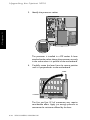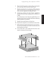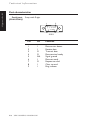
1
OWNER'S HANDBOOK
XEN
Pentium 60/66
apricot
MITSUBISHI ELECTRIC
OWNER'S HANDBOOK
Chapter
Microsoft, MS, and MS-DOS are registered trademarks, and Windows is a trademark, of Microsoft
Corporation.
IBM is a registered trademark, and VGA and PS/2 are trademarks, of International Business
Machines Corporation.
Intel is a registered trademark, and Pentium and OverDrive are trademarks, of Intel Corporation.
Information contained in this document is subject to change without notice and does not
represent a commitment on the part of Apricot Computers Limited. Any software described in
this manual is furnished under a license agreement. The software may be used or copied only in
accordance with the terms of this agreement. It is against the law to copy any disk supplied for any
purpose other than the purchaser’s personal use.
All rights reserved; no use or disclosure without written consent.
Copyright © Apricot Computers Limited 1994
Published by
Apricot Computers Limited
3500 Parkside
Birmingham Business Park
Birmingham B37 7YS
MITSUBISHI ELECTRIC
Printed in the United Kingdom
Part No. 15273131
Revision 01
Safety and Regulatory Notices
Safety and Regulatory Notices
The Apricot XEN uses a safety ground and must be earthed.
The system unit AC power cord is its “disconnect device”.
Ensure that the system unit is positioned close to the AC
power outlet, and that the plug is easily accessible.
It is imperative that the Apricot XEN is set to the correct
voltage range before use. If not, the machine may be irreparably
damaged.
Turn off the Apricot XEN and unplug all power cords before
moving the system unit, cleaning the computer or removing the
system unit top cover.
The CD-ROM drive contains a laser system which is harmful to
the eyes, and is classified as a CLASS 1 LASER PRODUCT
according to IEC 825 Radiation Safety of Laser Products (Equipment
Classification: Requirements & User's Guide). Do not attempt to
disassemble the CD-ROM drive; if a fault occurs, call an
authorized Apricot maintainer. Use the CD-ROM drive only as
described in this manual; failure to do so may result in exposure
to hazardous radiation.
To prevent fire and electric shock, do not expose any part of
the system unit to rain or moisture.
When positioning the Apricot XEN system unit, monitor and
keyboard, take into account any local or national regulations
relating to ergonomic requirements.
The Real Time Clock chip on the motherboard includes a lithium
battery. This component may explode if handled incorrectly.
Do not attempt to recharge, disassemble or dispose of in fire.
Keep away from children.
Do not dispose of the Real Time Clock chip, or any assembly
which contains it in domestic waste.
XEN OWNER'S HANDBOOK
I
Safety
Read the separate Power Connection Guide before using the
Apricot XEN for the first time. Information in the Owner’s
Handbook relating to connection to the AC power supply may
not apply outside the United Kingdom.
Safety and Regulatory Notices
Safety
Power cord
requirements
The power cord packed with the Apricot XEN complies with
the safety standards applicable in the country in which it is sold.
Use only this power cord; do not substitute a power cord from
any other equipment.
If you wish to use the computer in another country, you must
ensure that you use a power cord and plug which complies with
the safety standards of that country.
Plug
Standard
Countries
BS1363A
United Kingdom
SHUCO
Austria, Belgium, Finland,
France, Germany, Holland,
Italy, Norway, Sweden
250V
E
L
N
250V
E
N
L
250V
N
L
SRAF 1962/
DB16/87
Denmark
NEMA 5-15P
USA, Canada
ASE 1011
Switzerland
AS 3112-1981
Australia
E
125V
E
N
L
250V
250V
The power cord fittings must bear the certification mark of the
agency responsible for evaluation.
Refer to your authorized Apricot supplier if you ever require
additional or alternative power cables.
II
XEN OWNER'S HANDBOOK
Safety and Regulatory Notices
UK plug wiring instructions
The wire which is coloured blue must be connected
to the terminal which is marked with the letter N or
coloured black. The wire which is coloured brown
must be connected to the terminal which is marked
with the letter L or coloured red.
This appliance is supplied with a mains lead that
has a non-removable moulded plug. If the socket
outlets are not suitable for the plug supplied with
this appliance, it should be cut off and an
appropriate three-pin plug fitted.
Use a fuse approved by ASTA to BS1362, i.e.
carries the
mark.
ASA
Always replace the fuse cover, never use the plug
with the fuse cover omitted.
Note: The plug severed from the mains lead must
be destroyed, as a plug with the bared flexible
cord is hazardous if engaged in a live socket
outlet.
Replace with same colour fuse cover only.
Replacement fuse covers may be obtained from
your dealer.
The following wiring information should be
employed when adding the replacement plug.
WARNING THIS APPLIANCE MUST BE
EARTHED
The wires in the mains lead are coloured in
accordance with the following code:
Green and Yellow
Blue
Brown
Earth
Neutral
Live
This diagram
shows the wiring
inside the moulded
plug. Use it as a
guideline if you
need to re-fit a plug
of a similar type to
the mains lead.
As the colours of the wires in the mains lead of
this appliance may not correspond with the
coloured markings identifying the terminals in
your plug, proceed as follows.
E
L
N
The wire which is coloured green-and-yellow
must be connected to the terminal in the plug
which is marked with the letter E, or by the earth
or coloured green or green-andsymbol
yellow.
Noise levels
German Acoustic Noise Regulation
Sound power level is less than 70 dB(A) according to DIN
45635 Part 19 (ISO 7779).
Die Deutsche Akoustische Lärm-Regulierung
Der Grad der Klangstärke ist weniger als 70 dB(A) je nach DIN
45635 Teil 19 (ISO 7779).
CLASS 1
LASER PRODUCT TO IEC 825
LASER KLASSE 1
PRODUKT NACH IEC 825
The CD-ROM drive is
classified as a CLASS 1
LASER PRODUCT.
The CLASS 1 LASER
PRODUCT label is
located on the under
side of the system unit.
XEN OWNER'S HANDBOOK
III
Safety
IMPORTANT Power
Cable Connections
Safety and Regulatory Notices
Safety
Refer to the labels on the rear of your computer to establish which of the following warnings
apply.
FCC Class A
Warning - this equipment has been tested and found to comply with the limits for a Class A
computing device, pursuant to Subpart J of Part 15 of FCC rules. Only peripherals (computer
input/output devices, terminals, printer, etc.) certified to comply with the Class A limits may be
attached to this computer. Operation of this equipment in a residential area may cause
unacceptable interference to radio and television reception requiring the operator to take
whatever steps are necessary to correct the interference.
FCC Class B
Warning - this equipment has been certified to comply with the limits for a Class B computing
device, pursuant to Subpart J of Part 15 of FCC rules. Only peripherals (computer input/output
devices, terminals, printer, etc.) certified to comply with the Class B limits may be attached to this
computer. Operation with non-certified peripherals is likely to result in interference with radio
and TV reception.
Radio and television interference
The computer described in this manual generates and uses radio frequency energy for its
operation. If it is not installed and used properly, in strict accordance with the manual, it may
cause interference with radio and television reception.
The computer has been tested and found to comply with the RF emission limits for an FCC Class
B computing device which is intended to provide reasonable protection against such interference
in a residential installation. However, there is no guarantee that interference will not occur in a
particular installation.
If this equipment does cause interference with radio or television reception, which can be
determined by turning the equipment off and on, the user is encouraged to try to correct the
interference by one or more of the following measures:
• Move the computer away from the receiver being interfered with.
• Turn the computer with respect to the receiver.
• Turn the receiver with respect to the computer.
• Plug the computer into an outlet that is on a different branch circuit from the receiver.
• Disconnect and remove any I/O cables that are not being used.
• Unplug and remove any expansion cards that are not being used, and replace the relevant
blanking plates.
• Make sure that the computer is plugged into a grounded outlet.
If you need additional help, consult your supplier. You may find the following booklet helpful: How
to Identify and Resolve Radio-TV Interference Problems. This booklet is available from the US
Government Printing Office: Washington DC 20402 - Stock No. 004-000-000345-4.
DOC Class A
The computer described in this manual complies with: Canadian DOC radio interference
regulations CRCc 1374 governing Class A digital devices.
DOC Class B
The computer described in this manual complies with: Canadian DOC radio interference
regulations CRCc 1374 governing Class B digital devices.
IV
XEN OWNER'S HANDBOOK
CONTENTS
Chapter
Contents
CONTENTS
1
Introducing the Apricot XEN
2
Getting Started with the Apricot XEN
3
Operating the Apricot XEN
Using the front panel controls 3/2
Using the 3.5" diskette drive 3/3
Using the 5.25" floppy disk drive 3/4
Using the SLCD CD-ROM drive 3/5
Using the Irwin FTD tape drive 3/7
Using the SCSI QIC tape drive 3/9
Using the SCSI DDS or DDS-DC tape drive 3/12
Using the SCSI CD-ROM drive 3/16
Using the Apricot XEN abroad 3/20
4
Caring for the Apricot XEN
Cleaning the Apricot XEN 4/2
Transporting the Apricot XEN 4/6
XEN OWNER'S HANDBOOK I
Contents
General advice 2/2
Connecting the components 2/3
Turning on and booting the computer 2/4
Preparing a second hard disk 2/6
The software on your computer 2/6
Using the SETUP utility 2/7
Using Apricot Help 2/8
Contents
5
Upgrading the Apricot XEN
Contents
Expansion cards 5/2
Memory upgrades 5/6
Processor upgrades 5/9
Installing additional video RAM 5/12
5.25" drives 5/13
3.5" hard disk drives 5/19
6
Using the SETUP utility
Introduction 6/1
Invoking SETUP 6/1
Using SETUP 6/2
Opening menu 6/3
Standard CMOS SETUP 6/4
Date 6/4
Time 6/4
Floppy drive A: 6/4
Floppy drive B: 6/4
Drive C, D, E, F: type 6/4
Drive C, D, E, F: timeout 6/5
Keyboard 6/5
Base Memory 6/5
Extended Memory 6/5
Advanced CMOS SETUP 6/5
Typematic Rate Programming 6/5
Hit <F1> Message Display 6/5
System Boot-up Num Lock 6/6
System Boot-up Sequence 6/6
System Boot Up CPU Speed 6/6
Cache Memory 6/6
Network Password Checking 6/6
ISA Linear Frame Buffer 6/6
Set Linear Frame Address To 6/6
Disable Shadow Memory Size 6/7
Disable Shadow Memory Base 6/7
Base Memory Size 6/7
IDE DMA Transfer Mode 6/7
IDE Multiple Sector Mode 6/7
II
XEN OWNER'S HANDBOOK
Contents
7
Troubleshooting
Problems when starting 7/2
Troubleshooting charts 7/4
A
Inside the Apricot XEN
Anti-static precautions A/2
Removing the top cover A/3
Configuring expansion cards A/4
Motherboard jumper settings A/14
B
Technical Information
Specifications B/2
Physical characteristics B/6
Electrical characteristics B/7
Port characteristics B/8
XEN OWNER'S HANDBOOK III
Contents
Advanced CMOS SETUP continued
IDE LBA translation 6/7
Enhanced ISA Timing 6/8
ISA IRQ 9 6/8
ISA IRQ 10 6/8
ISA IRQ 11 6/8
Peripheral Management SETUP 6/8
Programming Option 6/8
Onboard Floppy Drive 6/8
Onboard IDE drive 6/9
First Serial Port Address 6/9
Second Serial Port Address 6/9
Parallel Port Address 6/9
IRQ active State 6/9
Parallel Port Mode 6/9
Configure with BIOS Defaults 6/9
Configure with Power-on Defaults 6/9
Change Password 6/10
Write to CMOS and Exit 6/10
Do Not Write to CMOS and Exit 6/10
INTRODUCING THE APRICOT XEN
Chapter 1
Chapter
Introducing the Apricot XEN
1
INTRODUCING THE
APRICOT XEN
The Apricot XEN Pentium 60/66, is ideally suited for use as high
performance, general-purpose personal computers, networked
business workstations and workgroup servers.
Read the separate Power Connection Guide before using
the Apricot XEN for the first time.
Chapter 1
XEN OWNER'S HANDBOOK 1/1
Introducing the Apricot XEN
Standard
features
The standard features of the Apricot XEN Pentium 60/66 range
include:
• Intel Pentium system processor with OverDrive upgrade
capability.
• Two full-length, one half length 16-bit Industry Standard
Architecture (ISA) expansion card slots, and one full
length PCI slot.
• Standard 8 Mbytes of motherboard random access
memory (RAM) upgradable to 128 Mbytes by the use of
single in-line memory modules (SIMMs).
• SETUP configuration utility in read-only memory (ROM).
• On-board high performance PCI bus video based on an
Chapter 1
ATI 68800AX controller. Equipped with at least 1 Mbyte
of video RAM.
• 256 Kbyte system memory cache.
• PCI Integrated Drive Electronics (IDE) disk drive system.
• Extended keyboard, two-button mouse, parallel and dual
serial ports.
• 1.44 Mbyte 3.5" diskette drive; 3.5" hard disk drive bay
with room for two one-inch drives; one 5.25" removable
media drive bay.
These standard features can be enhanced by various hard disk
and removable media drives, LAN adapter cards, and so on. For
an outline of these options, see Chapter 5, “Upgrading the
Apricot XEN”.
1/2
XEN OWNER'S HANDBOOK
Introducing the Apricot XEN
Unpacking
On unpacking the computer, you should find:
• Apricot XEN system unit.
• Apricot/Mitsubishi monitor and accompanying User’s
Guide.
• Apricot extended keyboard and two-button mouse.
• System unit AC power cord appropriate for the country
of sale.
• System documentation.
• Microsoft MS-DOS pack.
• Microsoft Windows pack (if the system has a hard disk).
Keep the cartons, boxes and packaging materials; you will need
them again if you have to transport the computer elsewhere.
Make a note of the manufacturer’s data recorded on the various
components (product codes, serial numbers, etc.). You may
need this information if the XEN develops a fault.
Instructions for removing the top cover are given in Appendix
A, “Inside the Apricot XEN”.
Turn off the Apricot XEN and unplug all power cords
before removing the top cover.
XEN OWNER'S HANDBOOK 1/3
Chapter 1
More elaborate systems may include software or hardware
options with accompanying installation diskettes and additional
documentation. Some of these options may have been factoryconfigured or installed by your Apricot supplier.
2
1
3
Chapter 1
4
5
Introducing the Apricot XEN
1/4
XEN OWNER'S HANDBOOK
Introducing the Apricot XEN
1
POWER button: press to turn the system on or off.
The green indicator on the button lights when the
system unit is powered.
2
activity indicators, from left to right:
lights when a diskette, floppy disk or Irwin tape
drive is accessed (depending on the operating system).
lights when a hard disk drive is accessed (depending
on the operating system).
door (shown closed): hinges down to reveal the
removable-media drive bay.
4
3.5" diskette drive: fitted as standard in every Apricot
XEN system.
5
system lock: prevents unauthorized access to the
inside of the system unit.
XEN OWNER'S HANDBOOK 1/5
Chapter 1
3
1
2
10
3
4
5
6
7
11
8
12
9
Chapter 1
10
13
Introducing the Apricot XEN
1/6
XEN OWNER'S HANDBOOK
Introducing the Apricot XEN
AC power outlet: where the monitor power cord
can plug in. Only Apricot-approved monitors should
be powered from this outlet.
2
voltage selection switch: the Apricot XEN can be
set to operate with a 100-120 volt or 220-240 volt AC
power supply.
3
AC power inlet: where the system unit AC power
cord plugs in.
4
keyboard port: connect the keyboard to this port.
5
mouse port: connect the (optional) Apricot mouse
to this port.
6
serial port 1: (110 baud to 14.4k baud): typically used
for connecting an external modem or a serial printer
signal cable.
7
serial port 2: (110 baud to 14.4k baud): typically used
for connecting an external modem or a serial printer
signal cable.
8
parallel port that supports EPP and ECP
features: typically used for a printer signal cable.
9
monitor port: connect the monitor signal cable to
this port (if you are using the on-board video controller).
10
casing screws: loosen these to remove the top cover.
11
security loop: you can feed a security chain or cable
through this loop and secure it to prevent theft of the
system unit.
12
blanking plates: for Industry Standard Architecture
(ISA) expansion card slots.
13
air vent: do not block this vent or the system will
overheat.
XEN OWNER'S HANDBOOK 1/7
Chapter 1
1
Introducing the Apricot XEN
1
2
3
6
4
Chapter 1
5
1/8
7
1
motherboard: see the label inside the system unit lid
for up-to-date information on the layout of the
motherboard.
2
expansion card slots: Three expansion slots, one half
length and one full length ISA, and one full length slot
which can be used by either an ISA or a PCI card. An
additional connector is provided on the rear of the
backplane, this is an Apricot proprietary connector which
may be used in future developments of the XEN range.
3
SIMM sockets: every XEN has 8 Mbytes of
motherboard memory which can be upgraded to 128
Mbytes by the use of single in-line memory modules.
4
processor socket: insert an OverDrive processor
here to upgrade the processing power of your Apricot
XEN.
5
5.25" removable-media drive bay: may be occupied
by a removable media drive.
6
3.5" hard-disk drive bay: this bay has room for two
one-inch high IDE hard disk drives.
7
3.5" diskette drive: fitted as standard in every Apricot
XEN system.
XEN OWNER'S HANDBOOK
GETTING STARTED WITH THE
APRICOT XEN
Chapter
Chapter 2
Getting started with the Apricot XEN
2
GETTING STARTED WITH THE
APRICOT XEN
You should read this chapter even if you do not read any other.
It provides important information to help you site, connect,
power and configure the Apricot XEN.
If you are familiar with the operation of personal computers,
this chapter will probably tell you all you need to know in order
to start working with your XEN. Chapter 3, “Operating the
Apricot XEN”, has more information about the use of the
various disk and tape drives with which the XEN may be fitted.
Read the separate Power Connection Guide before using
the Apricot XEN for the first time.
Chapter 2
XEN OWNER'S HANDBOOK 2/1
Getting started with the Apricot XEN
General advice
The Apricot XEN is designed to be used in a normal office
environment. Here are a few hints for choosing a suitable site:
• Place the XEN system unit flat on a sturdy, level surface.
Unlike some other computers, the system unit is not
designed to be stood on its side.
• Site the XEN away from moisture, direct sunlight, and
extremes of heat and cold. Avoid situations in which the
surrounding temperature or humidity may change rapidly.
See Appendix B, “Technical Information”, for
recommended temperature and humidity ranges.
• When positioning the XEN system unit, monitor and
keyboard, take into account any local or national
regulations relating to ergonomic requirements. For
example, you should ensure that little or no ambient light
is reflected off the monitor screen as glare, and that the
keyboard is placed in a comfortable position for typing.
• Give the XEN plenty of room so that air can circulate on
Chapter 2
all sides. Air is drawn into the system unit through the
vent on the left-hand side. Ensure that this vent is never
obstructed.
• Do not allow any cables, particularly power cords, to
trail across the floor where they can be snagged by people
walking past.
The Apricot XEN uses the system unit AC power cord
as its “disconnect device”. Ensure that the system unit
is positioned close to the AC power outlet, and that the
plug is easily accessible.
To prevent fire and electric shock, do not expose any
part of the system unit to rain or moisture.
2/2
XEN OWNER'S HANDBOOK
Getting started with the Apricot XEN
Connecting the components
See Chapter 1, “Introducing the Apricot XEN”, if you need
help indentifying the various ports on the system unit.
Checking
the AC
power supply
When your Apricot XEN is delivered, it is ready for the
commercial AC power supply generally available in the country
in which it is sold. It has been set for the correct voltage range,
and is supplied with an AC power cord and plug which comply
with the relevant safety standards.
Before using your XEN in a country other than which it was
originally sold, you must check the voltage and frequency of
that country’s AC power supply, and the type of power cord
required there.
If necessary, the AC voltage setting of the Apricot XEN can be
adjusted by the voltage selection switch on the rear of the
system unit (see the section on “Using the Apricot XEN abroad”
in Chapter 3, “Operating the Apricot XEN”). Note that the
monitor’s voltage setting will probably also need adjusting;
consult the User’s Guide that accompanies the monitor, or ask
your Apricot supplier for help.
Installing
add-on
options
If your XEN arrived with uninstalled add-on options, (such
expansion cards or memory modules) consult Chapter 5
"Upgrading the Apricot XEN" for step-by-step instructions
installing them. Expansion cards may also have their own
documentation.
Note that some options for which you have installation guides
may have already been installed for you at the factory or by your
Apricot supplier.
XEN OWNER'S HANDBOOK 2/3
Chapter 2
The “Safety and Regulatory Notices” section at the start of the
Owner’s Handbook includes advice about suitable power cords.
Getting started with the Apricot XEN
Connecting
the
components
Having assured yourself that the voltage settings and the AC
power cords of the computer, the monitor and any other
peripherals are correct:
1.
If your AC power outlets have switches, set them to
their Off positions.
2.
Ensure that the system unit, the monitor, and any
peripherals are turned off.
3.
Connect signal cables and power cords (in that order)
to their respective ports and inlets on the XEN system
unit, the monitor, and any peripherals. Make sure the
cables are connected securely.
Chapter 2
When you plug the keyboard cable into the rear of the
XEN, be careful not to plug it into the mouse port by
mistake. Never plug a keyboard or mouse in with the
system powered up.
4.
Connect the system unit and peripheral power cords
to nearby, grounded AC power outlets.
5.
If your AC power outlets have switches, set them to
their On positions.
Your Apricot XEN is now ready to use. The rest of this chapter
tells you how to turn your XEN on and off, and how to configure
it using the built-in SETUP utility.
Turning on and booting the computer
Turning the
power on
To turn on the Apricot XEN, simply press the POWER button. The
green indicator on the POWER button lights to show that the
system unit is powered. Remember that the monitor has own
power control; see the monitor’s User’s Guide for details.
Always make sure that the XEN is turned on before turning on
any attached peripherals, particularly a printer attached to the
parallel port. The computer's parallel port is vulnerable to
surges in the AC power supply, which can be passed onto it via
the printer's parallel cable.
2/4
XEN OWNER'S HANDBOOK
Getting started with the Apricot XEN
Power-on
self-test
Whenever the XEN is turned on, the power-on self-test (POST)
routine tests various hardware components, including memory,
and checks the computer’s configuration. During this time, BIOS
sign-on and POST messages are displayed.
The boot
sequence
Provided that POST succeeds without discovering any serious
errors or configuration discrepancies, the XEN attempts to
find an operating system; that is, it attempts to boot. It will look
first for a system diskette, then for a bootable hard disk partition.
Turning the
power off
When you have finished using the XEN and want to turn it off,
be sure that any information you want to keep is stored on a
diskette or on a hard disk. Any information held in the computer’s
system memory will be lost when you turn off the computer.
Always turn off any attached peripherals first, particularly a
printer attached to the parallel port.
If you are logged-in to a network, log out before turning off the
computer. Similarly, close down or exit from any software
which employs virtual memory or disk-caching (for example,
Microsoft Windows v3.1x with SMARTDrive).
To turn off the XEN, simply press the POWER button again. The
green indicator on the button goes out. (Remember that the
monitor is powered from the system unit.)
After you turn the computer off, wait at least 5 seconds before
turning it on again. The computer may not initialize itself properly
if you turn it off then on again in quick succession.
XEN OWNER'S HANDBOOK 2/5
Chapter 2
Do not turn off the computer if any of the activity indicators on
the front panel are lit; this means that the computer is accessing
a drive. Wait until that operation is completed before turning
off the computer.
Getting started with the Apricot XEN
Preparing a second hard disk
Some Apricot XEN computers have two hard disk drives, known
as master and slave.
Apricot partitions and formats the master drive with Microsoft
MS-DOS at the factory. The drive is given a single primary DOS
partition, which is the active partition. When you turn the
computer on, it will boot (load its operating system) from the
master drive, which will appear as MS-DOS drive C.
The slave drive is not partitioned or formatted. You must
partition the slave drive with the MS-DOS Fdisk program, and
format the partitions with the Format command. Until you do
this, you will be unable to use the slave drive. See your MS-DOS
manual for instructions on using Fdisk and Format.
Chapter 2
Caution: When you run Fdisk, it assumes you want to work
with the first, or master, drive (it says the “Current fixed disk
drive” is “1”). To switch attention to the slave drive, choose
Select next fixed disk drive(option 5) from the main menu.
Of course, you may also want to use Fdisk to repartition the
master drive. If you decide to do this, be sure to make a back
up copy of all the information on the drive first, including MSDOS itself, as repartitioning will cause the master drive’s existing
contents to be lost.
The software on your computer
Apricot XEN computers with a hard disk drive arrive with
Microsoft MS-DOS and Microsoft Windows pre-installed.
Other software may be pre-installed by Apricot or your Apricot
supplier.
Hard disks also contain a copy of the Windows display driver
for the XEN video subsystem, but Windows is not configured
to use the driver. For instructions on changing the Windows
display setup refer to the mach32 help file in the Apricot
group within Windows.
2/6
XEN OWNER'S HANDBOOK
Getting started with the Apricot XEN
In addition to a working copy of MS-DOS, Windows and the
Windows display driver, your hard disk will contain images of
DOS and Windows installation diskettes, and any drivers
diskettes for your computer. A Windows utility is provided to
allow you to create copies of these diskettes. This utility is run
whenever you start Windows.
You will need a copy of the display driver diskettes should you
wish to install a display driver for a non-Windows application.
Refer to the mach32 help file in the Apricot group within
Windows for information on the drivers and utilities supplied.
Copies of the DOS and Windows diskettes will safeguard against
hard disk failure or you accidentally overwriting or deleting
files. It is recommended that you use the utility to create copies
of the diskettes soon after setting up your system.
Using the SETUP utility
What is
SETUP?
SETUP’s purpose is to allow you to view and alter your
computer’s configuration. To configure a computer means to
declare its hardware components, such as the amount of memory
it has or the type of monitor, and to say how you want them
to be used. Configuring your computer is often necessary to
ensure that the software you use can recognise and exploit the
system’s capabilities.
The configuration data is kept in a special part of the computer’s
memory, known as configuration memory or CMOS memory.
This memory is sustained by a small battery, so its contents are
preserved while the computer is turned off.
XEN OWNER'S HANDBOOK 2/7
Chapter 2
SETUP is a configuration utility programmed into the
XEN’s read-only memory (ROM). Because it is permanently
kept in ROM, SETUP does not need an operating system to
function and can be invoked whenever you wish to reconfigure
your computer.
Getting started with the Apricot XEN
Your XEN arrives preconfigured, but may need to be
reconfigured after you add or remove add-on options such as
memory modules or expansion cards.
Invoking
SETUP
The SETUP utility can be invoked during the power up sequence.
It is invoked by pressing the DEL or F1 key.
Once you have reconfigured your computer you can exit SETUP.
The XEN will then automatically reboot, and the changes come
into effect.
A full description of the SETUP utility is given in Chapter 6
"Using the SETUP utility".
Using Apricot Help
Along with the software preinstalled on your hard disk you will
find an Apricot Help file. This explains what software is on your
hard disk, and how to install drivers to use the enhanced features
of the system.
Chapter 2
Apricot Help may be supplied in various forms, according to
the target operating system. The two most common forms are
ASCII text files and Microsoft Windows help files.
Viewing
text files
ASCII text files, identified by their .txt file extensions, can be
read by most text editors and wordprocessing programs.
Alternatively they can be displayed, one screenful at a time,
using the DOS Type command; for example:
type helpfile.txt | more
Viewing
Windows
help files
Windows help files can be displayed only by the Microsoft
Windows Help program (v3.1 or later).
If your computer has a hard disk on which Apricot has preinstalled Microsoft Windows, copies of some Windows help
files may already be available as icons in the “Apricot” program
group. To view a help file, simply double-click on its icon, or
select the icon and press ENTER. For more information about
using Help, see your Windows documentation.
2/8
XEN OWNER'S HANDBOOK
Getting started with the Apricot XEN
If the Windows help file you want to view is not already installed,
or if for any other reason you need to view a Windows help file
directly from a diskette:
1.
Insert the diskette into a suitable drive.
2.
Use Windows File Manager to view the contents of the
diskette.
3.
Choose the help file, identified by its .hlp file extension,
either by double-clicking on its filename or by selecting
the filename with the cursor and then pressing ENTER.
The Windows Help program starts, displaying the first
topic in the help file. For more information about using
Help, see your Windows documentation.
Alternatively, you can copy the Windows help file from the
diskette to a hard disk or network drive, and create a program
item for it using Program Manager. The help file can then be
viewed at any time simply by double-clicking on its icon. To do
this:
Insert the diskette into a suitable drive. Copy the
Windows help file, and also the diskhelp.ico icon file,
from the diskette to a hard disk or network drive.
2.
Choose New from the File menu in Program Manager.
Select the Program Item option in the New Program
Object dialog box, then choose OK. The Program
Item Properties dialog box appears.
3.
In the Description text box, type the title of the diskette
from which the help file was copied.
4.
In the Command Line text box, type the path and
filename of the help file (including its .hlp extension).
5.
Choose Change Icon. The Change Icon dialog box
appears. In the File Name text box, type the path and
filename of the diskhelp.ico icon file. Choose OK.
6.
In the Program Item Properties dialog box, choose
OK. The dialog box closes and the Apricot disk help
icon appears in the program group.
XEN OWNER'S HANDBOOK 2/9
Chapter 2
1.
Getting started with the Apricot XEN
Chapter 2
All the help files provided by Apricot have a version number so
you can tell whether you’re looking at the most up-to-date
version. You can discover the version number of a Windows
help file by viewing it with Help and choosing About Help
from the Help menu.
2/10
XEN OWNER'S HANDBOOK
OPERATING THE APRICOT XEN
Chapter
Chapter 3
Operating the Apricot XEN
3
OPERATING THE APRICOT XEN
This chapter contains all you need to know for the day-to-day
operation of an Apricot XEN system. Note that the monitor
has its own User’s Guide.
Read the separate Power Connection Guide before using
the Apricot XEN for the first time.
Chapter 3
XEN OWNER'S HANDBOOK 3/1
Operating the Apricot XEN
Using the front panel controls
The Apricot XEN has only a few front panel controls and
activity indicators, and is very simple to use.
DISKETTE
ACTIVITY HARD DISK
INDICATOR ACTIVITY
INDICATOR
POWER
BUTTON
The POWER button is used to turn the computer on and off. The
green indicator in the button lights when the system is powered.
This button also controls the power supply through the AC
power outlet to the monitor.
There are two activity indicators on the front panel:
Inactive
Active
Meaning when active
Chapter 3
The XEN is using a 3.5" diskette
drive, a 5.25" floppy disk drive or
an FTD (floppy tape drive).
The XEN is using a hard disk drive.
3/2
XEN OWNER'S HANDBOOK
Operating the Apricot XEN
Using the 3.5" diskette drive
The 3.5" diskette drive can read and write double-sided diskettes
with a formatted capacity of either 1.44 Mbytes (if marked
“HD” or “high density”) or 720 Kbytes (if marked “DD” or
“double density”).
Each diskette has a rigid plastic cover with a metal shutter that
guards the disk surface. The drive automatically moves the
shutter aside to read the diskette. Never touch the exposed
surface under the shutter.
Keep diskettes well away from dust, moisture, magnetic objects,
and equipment that generates magnetic fields. Also, avoid
extremes of temperature and exposure to direct sunlight.
Otherwise, data recorded on the diskette may become
corrupted.
Inserting a
diskette
Insert the diskette into the slot with the arrowhead on the face
of the diskette pointing towards the drive. Push the diskette in
until it engages with the drive mechanism.
Chapter 3
XEN OWNER'S HANDBOOK 3/3
Operating the Apricot XEN
Removing
a diskette
Before attempting to remove a diskette, ensure that the drive
is not currently in use (the diskette activity indicator must be
unlit).
Press the EJECT button. The drive mechanism disengages and
the diskette is ejected halfway out of the drive.
Writeprotecting
a diskette
A diskette can be write-protected by sliding the small tab toward
the edge of the diskette to expose the little hole beneath it (as
shown below). With the tab in this position, you can read or
print files from the diskette, but you cannot create, rename or
delete any files.
PROTECTED
UNPROTECTED
Using the 5.25" floppy disk drive
Your Apricot XEN may be configured with a 5.25" floppy disk
drive. This drive can read and write double-sided disks with a
formatted capacity of either 1.2 Mbytes (if marked “HD” or
“high density”) or 360 Kbytes (if marked “DD” or “double
density”).
Chapter 3
Each floppy disk is sealed into a flexible plastic envelope with a
long, rounded aperture through which the read/write heads of
the disk drive can meet the disk surface. You must never touch
the exposed surface of the disk yourself.
Keep floppy disks well away from dust, moisture, magnetic
objects, and equipment that generates magnetic fields. Also,
avoid extremes of temperature and exposure to direct sunlight.
Otherwise, data recorded on the disk may become corrupted.
3/4
XEN OWNER'S HANDBOOK
Operating the Apricot XEN
Inserting a
floppy disk
Insert the disk into the drive slot with the read/write aperture
foremost. When the disk is fully inserted, turn the locking lever
one-quarter turn clockwise to engage the drive mechanism.
Removing a
floppy disk
Before attempting to remove a disk, ensure that the drive is not
currently in use (the drive’s LED must be unlit).
Turn the locking lever one-quarter turn counter-clockwise to
disengage the drive mechanism. The diskette is ejected halfway
out of the drive.
Writeprotecting
a floppy disk
A floppy disk can be write-protected by covering the small
notch in the edge of the disk envelope with a self-adhesive tab
(such tabs are typically supplied with new floppy disks). With
the tab in this position, you can read or print files from the disk,
but you cannot create, rename or delete any files.
WRITE-PROTECT
NOTCH
WRITE-PROTECT
TAB AFFIXED
Using the SLCD CD-ROM drive
The software required to control the SLCD drive depends on
your operating environment; see the Apricot Help provided
with your computer or ask your Apricot supplier for details.
With the appropriate software support, the SLCD drive can
retrieve multimedia data from CD-ROM discs and multisession
Photo-CD discs. It can also play commercial audio CDs. By
default, the drive spins at double normal speed except when
reading audio CDs.
XEN OWNER'S HANDBOOK 3/5
Chapter 3
Your Apricot XEN may be configured with an SLCD CD-ROM
drive. The SLCD drive requires an additional drive controller
expansion card.
Operating the Apricot XEN
The drive has its own headphone jack with associated volume
level control.
DISC DRAWER
COMPACT
HEADPHONE JACK
AND HEADPHONE LEVEL
BUSY
INDICATOR
EMERGENCY
EJECT HOLE
EJECT
BUTTON
Do not attempt to move the computer while a CD is in the
drive, especially if the CD is being played at the time.
The laser beam inside the SLCD CD-ROM drive is
harmful to the eyes. Do not attempt to disassemble
the CD-ROM drive. If a fault occurs, call an authorized
Apricot maintainer.
Chapter 3
Inserting a
compact disc
Removing a
compact disc
Press the EJECT button on the front of the drive to eject the
platter halfway out of the drive; note that the EJECT button will
not work unless the computer is turned on. Pull the platter out
to its fullest extent. Place the CD face up on the platter and
push the platter in until it engages with the drive mechanism.
Wait for the CD to spin up to speed before attempting to read
from it.
Before attempting to remove a CD, ensure that the drive is not
currently in use (the drive’s activity indicator must be unlit).
Press the EJECT button. The drive mechanism disengages and
the platter is ejected halfway out of the drive.
The EJECT button can be disabled by the software controlling
the CD-ROM drive. In this case pressing the EJECT button will
have no effect.
3/6
XEN OWNER'S HANDBOOK
Operating the Apricot XEN
To eject the drawer manually (for example, during a power
failure) you must first ensure that the computer is turned off.
Then insert a thin metal rod (such as an unwound paper clip)
into the emergency eject hole and push (see below).
COMPACT
Keep CDs well away from dust and moisture, and avoid touching
the surface of the CD. Also, avoid extremes of temperature
and exposure to direct sunlight.
Using the Irwin FTD tape drive
Your Apricot XEN may be configured with a 120 Mbyte Irwin
FTD (floppy tape drive). The Irwin FTD is so called because it
uses the on-board diskette/floppy disk interface and so does
not require an additional drive controller card like most other
tape drives.
Note that, although the drive is intended for use with 120
Mbyte cartridges, it is possible to read data previously recorded
on 40 Mbyte cartridges.
The tape drive can be damaged by incorrect insertion or removal
of cartridges, so always observe the following procedures:
XEN OWNER'S HANDBOOK 3/7
Chapter 3
The software required to control the tape drive depends on
your operating environment; ask your Apricot supplier for
details.
Operating the Apricot XEN
Inserting a
cartridge
1.
Remove the cartridge from its plastic holder.
2.
Hold the cartridge so that the metal plate faces
downwards, as shown below. Slide the cartridge into
the drive slot until you feel a slight resistance.
ACTIVITY
INDICATOR
WRITE-PROTECT
TAB
EJECT
BUTTON
METAL PLATE
Chapter 3
Removing a
cartridge
Writeenabling
a cartridge
3.
Carefully push the cartridge in a bit further until it
engages with the drive mechanism.
1.
Do not attempt to remove a cartridge while it is being
accessed by the computer (the drive’s activity indicator
must be unlit).
2.
Press the eject button then, pull the cartridge carefully
out of the drive slot, holding it between thumb and
forefinger.
3.
Return the cartridge to its plastic holder. This protects
the cartridge and prevents dust from collecting on the
surface of the tape.
A cartridge is normally write protected but can be write-enabled
by sliding the tag labelled <RECORD in the direction of the arrow
(that is, to the left). A cartridge must be write-enabled if you
intend to write data onto the tape.
Keep your tape cartridges well away from magnetic objects,
and equipment that generates magnetic fields. Avoid extremes
of temperature and exposure to direct sunlight; otherwise, the
data recorded on the tape may become corrupted.
3/8
XEN OWNER'S HANDBOOK
Operating the Apricot XEN
Using the SCSI QIC tape drive
Your Apricot XEN may be configured with a SCSI QIC tape
drive for quarter-inch tape cartridges. The software required
to control the QIC tape drive depends on your operating
environment; ask your Apricot supplier for details.
Apricot currently supplies 150 Mbyte and 525 Mbyte QIC tape
drives. However, these capacities depend on the type of cartridge
and the recording format used.
• The 525 Mbyte drive can use either DC6320 (600 ft, 320
Mbyte) or DC6525 (1000 ft, 525 Mbyte) cartridges and
can read and write in QIC-525, QIC-150 and QIC-120
formats.
• The 150 Mbyte drive can use DC6150 (600 ft, 150 Mbyte)
cartridges and can read and write in QIC-150 and QIC120 formats.
Both drives can also read from (but not write to) a QIC-24
formatted tape.
The drive automatically senses the cartridge type and uses the
maximum density QIC format possible for that cartridge
(thereby giving its nominal capacity) unless the cartridge has
already been used in a lower-density format.
The tape drive can be damaged by incorrect insertion or removal
of cartridges, so always observe the following procedures:
XEN OWNER'S HANDBOOK 3/9
Chapter 3
Apricot does not supply, support or recommend the use of
1000 ft, 250 Mbyte cartridges with the 150 Mbyte drive. If you
must use 1000 ft cartridges with the 150 Mbyte drive,
do not use 600 ft cartridges on the same drive. The
different cartridges produce different patterns of wear on the
read/write heads, resulting in increased error rates and reduced
head life. Standardize on one length only (preferably 600 ft) to
get the best performance from your drive.
Operating the Apricot XEN
Chapter 3
Inserting a
cartridge
Removing a
cartridge
3/10
1.
Check that the green indicator on the tape drive
is not lit. This indicates that the drive is ready to accept
a cartridge.
2.
Remove the cartridge from its plastic holder.
3.
Insert the cartridge as shown below. Push the cartridge
gently into the drive as far as it will go.
4.
Push the control lever to the right to engage the
mechanism.
1.
Do not attempt to remove the cartridge while it is
being accessed by the computer (that is, while the
green indicator is lit).
2.
Push the control lever to the left to release the
mechanism.
XEN OWNER'S HANDBOOK
Operating the Apricot XEN
Writeprotecting
a cartridge
3.
Push the control lever further to the left (you will feel
a slight resistance as you do so) until the cartridge
springs a short way out of the drive.
4.
Pull the cartridge out of the drive slot.
5.
Return the cartridge to its plastic holder. This protects
the cartridge and prevents dust from collecting on the
surface of the tape.
A cartridge can be write-protected by turning the circular plastic
plug in the top left corner of the cartridge so that it points to
SAFE. The plug can be turned with a screwdriver or the edge
of a coin.
SAFE
UNSAFE
POSITION
With the plug in this position, data can be read from the tape
but not written to it.
Keep your tape cartridges well away from magnetic objects,
and equipment that generates magnetic fields. Avoid extremes
of temperature and exposure to direct sunlight; otherwise, the
data recorded on the tape may become corrupted.
XEN OWNER'S HANDBOOK
3/11
Chapter 3
SAFE
POSITION
SAFE
Operating the Apricot XEN
Using the SCSI DDS or DDS-DC tape drive
Your Apricot XEN may be configured with a SCSI DDS (Digital
Data Storage) or SCSI DDS-DC (Digital Data Storage with
Data Compression) tape drive. The software needed to control
the drive depends on your operating environment; ask your
Apricot supplier for details.
The DDS-DC drive differs from the DDS drive in that it uses
a built-in compression algorithm which can typically double,
and in some cases quadruple, tape capacity. Data compression
and decompression is transparent to the host software.
The DDS-DC drive is illustrated below; the DDS drive is similar
except that the LED indicators and EJECT button are in different
positions. The way you use the drive and the meaning of the
indicators is the same for both types.
CASSETTE INSERTION SLOT
CASSETTE IN PLACE (GREEN)
EJECT BUTTON
Chapter 3
DRIVE BUSY (AMBER)
The DDS-DC and DDS drives use standard 60-metre or 90metre digital cassettes bearing the DDS symbol. The DDS-DC
drive writes compressed data by default, unless it finds
uncompressed data already on the cassette. The drive can also
write uncompressed data under software control. When reading
a cassette, the DDS-DC drive automatically distinguishes
compressed and uncompressed data and either decompresses
it or passes it through unaltered as appropriate.
3/12
XEN OWNER'S HANDBOOK
Operating the Apricot XEN
Use only cassettes bearing the DDS symbol; you cannot
play audio DAT cassettes with these drives.
The DDS drive has a nominal capacity of 1.3 Gbytes on a 60metre cassette, with a sustained transfer rate of 183 Kbytes/
second.
The DDS-DC drive writing uncompressed data has a nominal
capacity of 1.3 Gbytes on a 60-metre cassette or 2.0 Gbytes
on a 90-metre cassette, with a sustained transfer rate of 366
Kbytes/second. At a data compression ratio of 4:1 the DDSDC drive has a nominal maximum capacity of 5.2 Gbytes on
a 60-metre cassette or 8.0 Gbytes on a 90-metre cassette; the
sustained transfer rate is increased by the same ratio. However,
the actual compression ratio and transfer rate achievable in
any particular case depend on the characteristics of the data
being compressed, and may be higher or lower than these
nominal figures.
Interpreting
the LED
indicators
There are two LED (light-emitting diode) indicators on the
drive's front panel. The Cassette in Place (green) and Drive
Busy (amber) LEDs show the status of the drive:
Amber
Drive status
On
Off
Cassette inserted
On
On
Cassette inserted: tape being read or written
Flashing
slowly
On/Off
Media warning
Flashing
rapidly
On
Drive could not write to tape correctly
On/Off
Flashing
rapidly
Hardware error or high humidity
XEN OWNER'S HANDBOOK
Chapter 3
Green
3/13
Operating the Apricot XEN
Media
warning
A media warning, when the Cassette in Place (green) LED
flashes slowly, indicates that the tape may be becoming unreliable,
although at this point no data has been lost. First, clean the tape
head cylinder with the special cleaning cassette available from
Apricot, then try the data cassette again. If the warning persists,
copy the data onto a new cassette and discard the old one.
A media warning can also indicate that a prerecorded audio
DAT cassette has been inserted by mistake.
Drive could not write to tape
If the Cassette in Place (green) LED flashes rapidly, this means
that the drive could not write to the tape correctly, and indicates
that the tape has become unreliable. Remove the cassette and
use another.
Hardware error or high humidity
If the Drive Busy (amber) LED flashes rapidly, this indicates
either a hardware error or dew (high humidity). If this happens
soon after powering-up the computer, the drive’s diagnostic
test may have failed, in which case the drive will not operate.
Request help from your Apricot supplier or an authorized
Apricot maintainer.
Chapter 3
If the drive detects high humidity, the tape is automatically
ejected. As soon as the drive detects that the humidity is at an
acceptable level, it will return to normal operation.
Automatic
drive
operation
To prolong the life of the tape and the drive mechanism, the
drive “relaxes” during periods of inactivity (no read or write
operations):
• After 30 seconds, the capstan and pinch roller are released
and tape tension is removed.
• After 90 seconds, the tape is pulled away from the head
cylinder, and the cylinder stops rotating.
3/14
XEN OWNER'S HANDBOOK
Operating the Apricot XEN
Inserting a
cassette
Insert the cassette into the slot with the triangular arrowhead on
the cassette pointing towards the drive. As the tape is inserted, the
drive takes it and automatically loads it into the drive mechanism.
A load sequence checks ambient humidity, the tape format and
data integrity. Unless the tape is blank the tape log, which contains
a history of usage of the tape, is read into the drive’s memory.
The drive will automatically format a blank tape when data is
first written to it. Remember to allow time for the formatting
process when you use a new tape.
Removing
a cassette
Before attempting to remove a cassette, ensure that the drive
is not currently in use (the amber Drive Busy indicator must be
unlit).
XEN OWNER'S HANDBOOK
3/15
Chapter 3
Press the EJECT button on the front of the drive (depending on
your operating environment, the EJECT button may be disabled
while the drive is in use). If the tape is write-enabled, a copy
of the tape log, held in the drive’s memory, is written back to
tape. The drive rewinds to the beginning of the tape, unthreads
it, and ejects the cassette. Several seconds may pass between
the button being pressed and the cassette being ejected, so be
careful not to turn off the computer before the operation is
completed.
Operating the Apricot XEN
Writeprotecting
a cassette
A cassette can be write-protected by sliding the white tab on the
cassette so that the recess is revealed. In this position, data can be
read from the tape but not written to it.
WRITE
ENABLED
WRITE
PROTECT
The tape log, which includes a record of data integrity failures,
cannot be updated while the cassette is write-protected. It
follows that the tape log becomes inaccurate if a cassette is used
while write-protected, and the media warning LED status cannot
be relied upon to determine if the cassette needs to be copied
and replaced.
Keep your cassettes well away from magnetic objects, and
equipment that generates magnetic fields. Avoid extremes of
temperature and exposure to direct sunlight; otherwise, the
data recorded on the tape may become corrupted
Using the SCSI CD-ROM drive
Chapter 3
Your Apricot XEN may be configured with a SCSI CD-ROM
(Compact Disc ROM) drive. The software required to control
the CD-ROM drive depends on the your operating environment;
ask your Apricot supplier for details.
With the appropriate software support, the drive can retrieve
multimedia data from CD-ROM and Photo-CD (single and
multisession) discs. It can also play commercial audio CDs. By
default, the drive spins at double normal speed except when
reading audio CDs.
3/16
XEN OWNER'S HANDBOOK
Operating the Apricot XEN
The drive has its own headphone jack with associated volume
level control.
DISC CADDY SLOT
CD Caddy
COMPACT
HEADPHONE JACK
AND HEADPHONE LEVEL
BUSY
INDICATOR
EJECT
BUTTON
EMERGENCY
EJECT HOLE
Do not attempt to move the computer while a CD is in the
drive, especially if the CD is being played at the time.
The laser beam inside the SCSI CD-ROM drive is
harmful to the eyes. Do not attempt to disassemble
the CD-ROM drive. If a fault occurs, call an authorized
Apricot maintainer.
Inserting a
compact disc
The SCSI CD-ROM drive uses a special removable disc caddy
to hold a CD within the drive mechanism. The caddy has a metal
shutter that guards the disc’s surface; the drive automatically
moves the shutter aside to read the disc. One disc caddy is
provided free with the drive; more can be obtained from your
Apricot supplier. Use only disc caddies supplied by Apricot.
1.
Ensure that the computer is turned on and that the
drive is empty (the legend “CD Caddy” should appear
on the flap covering of the drive slot).
XEN OWNER'S HANDBOOK
3/17
Chapter 3
Do not confuse a CD’s storage case with a proper disc
caddy; if you attempt to insert a disc storage case you
will damage the drive.
Operating the Apricot XEN
2.
If there is a protective film on the centre of the caddy
lid, remove it before using the caddy.
3.
To open the caddy, press the tabs on both edges at the
end opposite the shutter.
4.
Set the disc, with its label upward, in the caddy. Handle
the disc only by its edge.
5.
Close the lid of the caddy firmly.
6.
Insert the caddy into the slot of the drive with the
disc’s label facing up and the arrow on the caddy
pointing towards the drive (that is, shutter end
foremost). Push the caddy in until it is completely
swallowed up by the drive.
Chapter 3
The drive begins reading the disc’s table of contents. The drive’s
activity indicator lights while the table of contents is being read.
When the activity indicator goes out, the drive is ready for use.
If the activity indicator remains on, this may indicate that the
disc is not properly positioned within the caddy. In this case,
press the EJECT button to remove the caddy and try again. If the
problem persists, consult your Apricot supplier or an authorized
Apricot maintainer.
Note too that the software controlling the CD-ROM drive may
be able to prevent the insertion of a disc.
3/18
XEN OWNER'S HANDBOOK
Operating the Apricot XEN
Removing a
compact disc
1.
Ensure that the computer is turned on (otherwise the
EJECT button will not work) and that the drive is not
currently in use (the drive’s activity indicator must be
unlit).
2.
Press the EJECT button. The drive mechanism disengages
and the caddy is partially ejected from the drive.
The EJECT button can be disabled by the software
controlling the CD-ROM drive. In this case pressing
the EJECT button will have no effect.
To eject the drawer manually (for example, after a power
failure) you must first ensure that the computer is turned off.
Then insert a thin metal rod (such as an unwound paper clip)
into the emergency eject hole and push hard (see below). The
rod must be at least 35 mm long.
CADDY LOADED
COMPACT
Keep CDs and caddies well away from dust and moisture.
Avoid touching the surface of the disc; for example, when the
disc is inside a caddy, do not open the shutter manually and
touch the disc. Also, avoid extremes of temperature and
exposure to direct sunlight.
XEN OWNER'S HANDBOOK
3/19
Chapter 3
Caring for
compact discs
Operating the Apricot XEN
Using the Apricot XEN abroad
Your Apricot XEN arrives ready to work with the commercial
AC power supply available in the country in which it is first sold.
If you plan to use your XEN in another country, you should first
check the following facts about your destination:
1. The voltage and frequency of the commercial AC power
supply.
2. The type of plug required for the AC power outlets.
The XEN can function within two alternative AC power supply
ranges, according to the position of the voltage selection switch
on the rear of the system unit:
Switch setting
115
230
AC power supply
(voltage and frequency)
100 - 120 volt AC, 50 - 60 Hz
220 - 240 volt AC, 50 - 60 Hz
It is imperative that the Apricot XEN is set to the
correct voltage range before use. If not, the machine
may be irreparably damaged.
The voltage setting of the monitor must always be the same as
the voltage setting of the system unit. See the User’s Guide that
accompanies the monitor or consult your Apricot supplier to
find out how to change the voltage setting.
Chapter 3
Make sure that the Apricot XEN and its monitor are returned
to their original voltage settings when you return home.
The AC power cord and plug supplied with the Apricot XEN
comply with the safety standards applicable in the country in
which it is first sold. If you plan to use your computer in another
country, you must get a power cord that complies with the
safety standards of the destination country. For further details,
see the “Safety and Regulatory Notices” section at the start of
this handbook.
See Chapter 4, “Caring for the Apricot XEN”, for more
information about transporting the XEN.
3/20
XEN OWNER'S HANDBOOK
CARING FOR THE APRICOT XEN
Chapter
Chapter 4
Caring for the Apricot XEN
4
This chapter provides information on how to care for your
computer. The Apricot XEN requires little physical maintenance
other than occasional cleaning. But you must take care when
transporting it to avoid damage to its delicate components,
particularly the hard disks.
XEN OWNER'S HANDBOOK 4/1
Chapter 4
CARING FOR THE
APRICOT XEN
Caring for the Apricot XEN
Chapter 4
Cleaning the Apricot XEN
Turn off the Apricot XEN and unplug all power cords
before cleaning the computer.
If you have any problems with the Apricot XEN which can’t be
resolved by cleaning it, consult the “Troubleshooting” chapter.
The
system unit
Do not use sprays, solvents or abrasives that might damage the
computer’s surface. Do not use cleaning fluids or sprays near
air vents, ports, or removable-media drives.
• Occasionally wipe the system unit with a soft, slightly
damp, lint-free cloth.
• Occasionally wipe the air vents on the rear and sides of
the system unit. Dust and fluff can block the vents and
limit the airflow.
• Occasionally clean the diskette drive using a proprietary
head cleaner.
The
monitor
4/2
Occasionally wipe the monitor with a soft, slightly damp, lintfree cloth. It is best to use anti-static glass cleaner on the
monitor screen, but do not spray glass cleaner directly onto the
screen; it could run down inside the case and damage the circuitry.
XEN OWNER'S HANDBOOK
Caring for the Apricot XEN
When necessary, clean the keycaps with a slightly damp cloth
and a minimum amount of a non-abrasive cleaning agent.
Take care not to spill any liquid onto the keyboard. Follow
these steps if you spill something on the keyboard and it stops
working:
1.
If the liquid is viscous, unplug the keyboard and call
your Apricot supplier or an authorized Apricot
maintainer.
2.
If the liquid is thin and clear, try unplugging the keyboard,
turning it upside down to let the liquid drain out, and
drying it for at least 24 hours at room temperature. If
the keyboard still won’t work, call your Apricot supplier
or an authorized Apricot maintainer.
If a solid object drops between the keys, turn the keyboard
upside down and shake it; do not probe between the keys as
this may cause damage.
The mouse
Dust and dirt may accumulate in the ball tracking mechanism of
the mouse. To clean the mouse:
1.
Unplug the mouse, turn it upside down and locate the plastic
cover that holds the ball in place. Depending on the model,
the plastic cover can be removed either by rotatingitcounterclockwise or by sliding it forward slightly.
2.
Remove the cover and set it aside.
3.
Cupping one hand over the underside, turn the mouse
back the right way up. The ball will drop into your hand.
4.
Blow gently into the mouse to remove any dust that
has collected there.
5.
Inside the mouse there are three plastic rollers. Using
a cotton swab moistened with a solvent cleaner, gently
wipe off any oil or dust that has collected on the rollers,
rotating them to reach all surfaces.
6.
Use clear water, or water with a mild detergent, to
clean the ball. Then dry it with a clean, lint-free cloth.
7.
Put the ball back in its socket and replace the plastic
cover. It should click into place.
XEN OWNER'S HANDBOOK 4/3
Chapter 4
The
keyboard
Caring for the Apricot XEN
Chapter 4
The
Irwin FTD
tape drive
You should clean the read/write head and the capstan of the
Irwin FTD frequently to prevent the accumulation of dust and
metallic particles.
If you notice read or write errors, or many bad blocks when
using the drive, be sure to clean the head and capstan thoroughly
before concluding that the drive or your tapes are defective.
The read/write head and the capstan are accessible through the
flip-up drive door, as shown below.
Although it is possible to use special kits to clean the drive,
Apricot recommends the use of 90% isopropyl alcohol and
several non-abrasive, lint free swabs, as follows:
1.
4/4
Gently rub an alcohol-dampened swab against the
surface of the read/write head. If the swab becomes
too discoloured, use additional swabs until there is no
further discolouration.
XEN OWNER'S HANDBOOK
Caring for the Apricot XEN
Rub an alcohol-dampened swab against the surface of
the capstan using an up and down motion. Gently rotate
the capstan and continue rubbing until the entire surface
is clean.
3.
Wait for at least one minute before using the tape
drive. This allows any residual alcohol to evaporate.
If you clean the read/write head first, and the swab is not too
discoloured, you may use the same swab to clean the capstan.
But if you clean the capstan first, you must not use the same
swab to clean the read/write head.
The
SCSI QIC
tape drive
You should clean the SCSI QIC tape drive after every 8 hours’
use, using the special cleaning kit available from your Apricot
supplier. Full instructions for cleaning are provided with this kit.
It is also advisable to clean the tape drive after the first use of
a new tape.
The SCSI DDS
or DDS-DC
tape drive
The read/write heads in the tape drive are protected during
normal operation by a built-in cleaning roller. In addition, a
special cleaning cassette is available from your Apricot supplier.
This cassette should be used:
• Every 25 operating hours.
• When a media warning status is indicated.
When you insert the cleaning cassette, the drive recognises it
as a cleaning cassette, runs it for about 20 seconds, then ejects
it automatically. Each time the cleaning cassette is used the
tape advances over an unused portion of the tape. If the drive
ejects the cleaning cassette immediately after you insert it, this
means that the entire tape has been used and a new cleaning
cassette is required. You cannot rewind a cleaning cassette.
Do not attempt to use an ordinary audio DAT cleaning cassette.
The drive will be unable to recognise it as a cleaning cassette.
XEN OWNER'S HANDBOOK 4/5
Chapter 4
2.
Caring for the Apricot XEN
Chapter 4
Transporting the Apricot XEN
Turn off the Apricot XEN and unplug all power cords
before moving the computer.
Use common sense when handling the Apricot XEN; hard
disks in particular can be damaged if the computer is dropped
or handled roughly. As a precaution, back up (copy) the contents
of your hard disks to tape or diskettes before moving the
computer.
Don’t try to move the computer while it is plugged into the AC
power supply or with any other cables, including network cables,
still attached.
When lifting and carrying the computer, grip the metal underside
of the system unit. Do not lift the unit by the plastic side trims
or the front bezel. Never attempt to use the door as a carrying
handle. Never attempt to lift the system unit with a monitor on
top.
If you need to transport the Apricot XEN any great distance,
use the original packing materials.
If you intend to use your Apricot XEN in another country, see
Chapter 3, “Operating the Apricot XEN”, for some important
advice.
4/6
XEN OWNER'S HANDBOOK
UPGRADING THE APRICOT XEN
Chapter
Chapter 5
Upgrading the Apricot XEN
5
UPGRADING THE APRICOT
XEN
This chapter contains instructions on installing add-ons and
upgrades in the XEN. The areas covered include:
expansion cards
additional memory
Chapter 5
•
•
•
•
•
processor upgrades
video RAM
additional drives
Read this chapter before purchasing an add-on or upgrade. If,
having read the relevant instructions, you are not confident
about installing the upgrade, you may wish to have your supplier
or service organisation install it for you.
Before you start installing the upgrade you should be thoroughly
familiar with all the relevant instructions.
Warning
Never carry out any work on the equipment with power applied.
Always switch off at the mains and remove the power lead from the
equipment before starting work.
Appendix A at the rear of this manual provides: a guide to
recommended anti-static precautions, instructions on removing
the system unit top cover, information on motherboard jumpers
and expansion card configuration.
The only tool required to complete the installation of any of the
upgrades is a small cross-head screwdriver.
XEN OWNER'S HANDBOOK 5/1
Upgrading the Apricot XEN
Inside the
system unit
The illustration below identifies the major components inside
the XEN system unit that are affected by the installation
instructions later in this section.
BLANKING
PLATES
POWER
SUPPLY
Chapter 5
EXPANSION
CARD
CONNECTORS
SIMM
SOCKETS
TM
DX2-66
486
3.5"
DRIVE BAY
intel
i
PROCESSOR
SOCKET
CARD
GUIDES
5.25"
DRIVE BAY
Expansion cards
Expansion cards, sometimes known as expansion boards, options
or adapters, are small self-contained circuit boards which extend
the capabilities of your computer. Here are just two examples:
• A graphics card can provide more specialized video
functions than those offered by the on-board video subsystem.
• A modem or facsimile card can provide a connection to
a telephone line.
The Apricot XEN has three expansion slots, one half length and
one full length 16-bit Industry Standard Architecture (ISA) and
one full length slot which can be used by either an ISA or a PCI
card. An additional connector is provided on the rear of the
backplane, this is an Apricot proprietary connector which may
be used in future developments of the XEN range. If your
computer has a Small Computer Systems Interface (SCSI) device
such as a QIC tape drive, one of these slots will be occupied by
an SCSI drive controller. Other cards may be pre-installed at
the factory or by your Apricot supplier.
5/2
XEN OWNER'S HANDBOOK
Upgrading the Apricot XEN
Expansion cards are a relatively cheap way of upgrading your
system. Moreover, they are usually quite easy to install, requiring
no more than a cross-head screwdriver and a steady hand.
Installation
Installation of an expansion card in the XEN is a simple process
requiring the removal of only the system unit cover and a
blanking plate. The following instructions and illustrations
describe how to install a card in a simple step-by-step sequence.
Power the system down.
2.
Take suitable anti-static precautions and remove the
system unit cover.
If you are unfamiliar with Apricot’s recommended antistatic precautions and/or the process of removing the
system unit cover refer to the appendices at the rear
of this manual.
3.
With the system unit cover removed, the space for
expansion cards will be visible. It is on the left side of
the system unit behind the activity indicators. Use the
illustration below to help you identify this area.
EXPANSION CARD
CONNECTORS
BLANKING PLATES
CARD GUIDES
At the rear of the area are three metal blanking plates,
one for each expansion card slot. These plates cover
slots in the rear of the system unit which will be used
by expansion cards.
At the front of the area are three guides. These ensure
that the front edge of any full length card is secured.
XEN OWNER'S HANDBOOK 5/3
Chapter 5
1.
Upgrading the Apricot XEN
4.
The blanking plates described above are each secured
by a screw. Using the following guidelines decide in
which of the available slots you wish to install the card,
then remove the appropriate blanking plate.
Chapter 5
In general it is easiest to start with the lowest slot and
work towards the top, but there a couple of exceptions.
If you are installing a card that uses the video feature
connector on the motherboard, it is best to install the
card in the lowest slot. If you are installing a drive
controller card that you want to connect to a drive in
the 5.25" drive bay it is easiest to install it in the top
slot.
To remove the blanking plate, first unscrew the securing
screw, then slide the plate out of its slot. Keep the
screw, you will use it later to secure the card.
5.
Your are now ready to install the card. However, before
you do so you must first ensure that the card is correctly
configured for your system.
Information on configuring cards for use in the XEN is
given in the Appendix A at the rear of this manual. Use
this information in conjunction with the documentation
supplied with your card to configure the card so that
it will not clash with any of the features on the XEN
motherboard, or any other expansion cards already
installed.
5/4
XEN OWNER'S HANDBOOK
Upgrading the Apricot XEN
6.
Position the expansion card alongside the slot in which
you wish to install it. Align the rear of the card with the
slot in the rear of the system unit, and, if the card is full
length, the front of the card with the card guide.
7.
Slide the card into the slot ensuring that the card edge
connector engages correctly with the backplane.
8.
Carefully push the card fully home. Do not apply
excessive pressure.
9.
Secure the card by replacing the screw that you
removed in step 4.
10. Connect any signal cables to the card.
11. Replace the system unit cover.
XEN OWNER'S HANDBOOK 5/5
Chapter 5
Note
If the card uses the video feature connector on the
motherboard, you must plug the video feature cable into
the motherboard socket before you install the card.
Upgrading the Apricot XEN
Memory upgrades
The XEN motherboard is fitted with sockets for four SIMMs
(Single In-line Memory Modules) these allow system RAM to be
expanded to up to 128Mbytes using standard 72 pin, 70 nS
SIMMs.
Chapter 5
The SIMM sockets are located at the front of the motherboard,
beneath the 5.25" drive bay.
SIMMs must be installed in pairs. Each pair is called a bank, bank
0 is formed by the pair of sockets nearest the hard disk drive
bay, bank 1 is formed by the pair nearest the processor.
Apricot supplies 1 Mbyte (256kx36), 2 Mbyte (512kx36), 4
Mbyte (1Mx36), 8 Mbyte (2Mx36), 16 Mbyte (4Mx36) and 32
Mbyte (8Mx36) SIMMs, giving upgrade capacities of 2, 4, 8, 16,
32 and 64 Mbytes. Any combination of these capacities is possible,
using any capacity in either of the two pairs.
Installation
In order to install a memory upgrade you must:
1.
Power the system down.
2.
Take suitable anti-static precautions and remove the
system unit cover.
If you are unfamiliar with Apricot’s recommended antistatic precautions and/or the process of removing the
system unit cover refer to Appendix A.
The SIMM connectors are located beneath the 5.25"
drive bay. In order to install a memory upgrade you
must remove the 5.25" drive bay.
3.
If there is a 5.25" drive fitted disconnect the power and
signal cables from the rear of the drive.
If no drive is fitted unclip the power cable from the
drive bay.
4.
5/6
Remove the two screws that secure the drive bay and
slide the bay backwards.
XEN OWNER'S HANDBOOK
Upgrading the Apricot XEN
5.
Lift the bay out of the system unit and put it down on
a safe flat surface.
Removing SIMMs
If you wish to install an upgrade in a bank which is already
occupied you must first remove the existing SIMMs.
For the first SIMM, lever the metal clips on each side
of the socket gently away from the SIMM using your
forefingers.
2.
Place your thumbs on the top edge of the SIMM and
move it gently towards the vertical.
3.
When the SIMM has rotated through 20°, taking care
to avoid touching any of the components on the SIMM,
grip the top corners of the SIMM between thumb and
first finger and carefully pull the SIMM out of the socket.
4.
Repeat steps 1 to 3 for the second SIMM.
Inserting SIMMs
Make sure that the pair of SIMMs you intend to install in a bank
are matching, then:
1.
The SIMMs will only install in one orientation. There
is a cutout at one end of the SIMM next to the connector
strip.
Hold the first SIMM with the cutout to the rear and the
metal connector strip nearest the motherboard.
XEN OWNER'S HANDBOOK 5/7
Chapter 5
1.
Chapter 5
Upgrading the Apricot XEN
2.
Position the SIMM above the socket with the SIMM
tilted slightly towards the front of the system unit.
3.
Lower the SIMM into the socket, and ensure that the
SIMM is properly located in the connector.
4.
Pushing gently on the top corners rotate the SIMM
towards horizontal until it clips into place. Do not use
excessive force.
If the SIMM will not rotate easily remove it and start
again.
5.
If the SIMM is properly located it should remain in
position held by the securing clips, and with a small
plastic lugs through the holes on either side of the
SIMM.
6.
Repeat steps 1 to 5 for the second SIMM.
If you wish to install SIMMs in the other memory bank repeat
the process above. Once you have completed installation you
can replace the 5.25" drive bay and reassemble the system.
1.
5/8
Replace the 5.25" bay in the system unit.
XEN OWNER'S HANDBOOK
Upgrading the Apricot XEN
Slide the bay forward until the two holes in the bay line
up with those in the hard drive assembly and the 5.25"
bay securing bracket.
3.
Replace the two screws that secure the 5.25" drive
bay.
4.
If there is a drive in the bay reconnect its power and
signal cables.
5.
Replace the system unit cover.
Processor upgrades
The XEN motherboard is fitted with a Zero Insertion Force
(ZIF) processor socket ready to accept any processor with a
Pentium compatible pinout, and an external clock speed of 60
or 66 MHz.
The motherboard includes one jumper to select the processor
clock speed (J7A1), and a second jumper to select the voltage
supplied to the processor (J13H3).
When shipped, the clock speed is set to match that of the
processor. The processor voltage is set to 5V for a 60MHz
system and 5.25V for a 66MHz system. It is likely that future
upgrade processors will require the jumper to be in the 5V
position. Refer to Appendix A for details of the jumpers.
Removing
the processor
Before installing the upgrade processor you must first remove
the existing processor. The processor is at the front left of the
motherboard. Instructions on locating the socket and removing
a processor are given below.
1.
Power the system down.
2.
Take suitable anti-static precautions and remove the
system unit cover.
If you are unfamiliar with Apricot’s recommended antistatic precautions and/or the process of removing the
system unit cover refer to the appendices at the rear
of this manual.
XEN OWNER'S HANDBOOK 5/9
Chapter 5
2.
Upgrading the Apricot XEN
Identify the processor socket.
TM
DX2-66
486
intel
i
Chapter 5
3.
TM
DX2-66
486
intel
i
The processor is installed in a ZIF socket. A lever
attached to the socket clamps the processor securely
in the socket when it is parallel to the motherboard.
4.
Carefully rotate the lever from the secure position
until it is perpendicular to the motherboard.
FREE
LOCKED
The first and last 15° of movement may require
considerable effort. Apply just enough pressure to
overcome the resistance offered by the lever.
5/10
XEN OWNER'S HANDBOOK
Upgrading the Apricot XEN
Installation
Once the processor is free of its socket lift it out of the
system unit and place it on the anti-static foam provided
with the upgrade processor.
1.
The upgrade processor and socket are keyed to ensure
that the processor can only be installed in one
orientation. The inside of one corner of the socket has
a key hole. The processor has a positioning guide in the
form of a small dot of paint.
2.
Carefully position the upgrade processor above the
socket with the positioning guide on the processor
over the keyed corner of the socket and the securing
lever in the perpendicular position.
PROCESSOR
IN CENTRE
Warning
If the processor is misaligned it will not go into the socket,
and any attempt to force it will damage the processor, or
the socket, or both.
3.
Gently insert the upgrade processor making sure that
it is correctly aligned with the socket and that you do
not bend or otherwise damage the pins.
XEN OWNER'S HANDBOOK
5/11
Chapter 5
5.
Upgrading the Apricot XEN
4.
Once you are certain that all the pins on the processor
are in the holes in the socket carefully move the securing
lever to the locked position.
Chapter 5
The lever may require a considerable amount of force
in order to lock the processor in place. Take care to
exert no more force than is necessary.
5.
Check that the clock speed and processor voltage
jumpers are set correctly for the new processor. Refer
to Appendix A and the documentation supplied with
the upgrade processor.
6
You may now reassemble the system unit.
Installing additional video RAM
The XEN motherboard is fitted with eight sockets which allow
the video RAM to be expanded from 1 Mbyte to 2 Mbytes using
eight 256k x 4 RAM chips.
1.
Power the system down.
2.
Take suitable anti-static precautions and remove the
system unit cover.
If you are unfamiliar with Apricot’s recommended antistatic precautions and/or the process of removing the
system unit cover refer to Appendix A at the rear of
this manual.
The video RAM sockets connectors are located at the left side
of the system unit beneath the adapter card slots, towards the
rear. In order to install a video RAM upgrade you must remove
any adapter cards installed in the system.
5/12
3.
If there are adapter cards fitted, disconnect any cables
connected to the cards.
4.
Remove the screws that secure the cards to the rear
of the system unit.
5.
Remove the cards.
XEN OWNER'S HANDBOOK
Upgrading the Apricot XEN
Identify the video RAM sockets from the following
illustration.
7.
One by one, carefully align the video RAM chips over
the sockets. Make sure that they are in the correct
orientation.
Pin 1
6.
Chapter 5
TM
DX2-66
486
intel
i
5.25" drives
The 5.25" drive tray in the XEN system unit can contain any half
height 5.25" device. Apricot supplies a range of tape and CDROM drives, and a 5.25" floppy drive, for this bay.
The following instructions describe the installation of a drive in
the bay. The Generic instructions apply to all drives, and describe
the physical installation of a drive.
Instructions specific to each drive type are given after the generic
instructions.
Generic
1.
Power the system down.
2.
Take suitable anti-static precautions and remove the
system unit cover.
XEN OWNER'S HANDBOOK
5/13
Upgrading the Apricot XEN
If you are unfamiliar with Apricot’s recommended antistatic precautions and/or the process of removing the
system unit cover refer to Appendix A.
TM
Chapter 5
DX2-66
486
intel
i
SECURING SCREWS
3.
Loosen the two screws that secure the drive bay and
slide the bay backwards.
4.
Lift the bay out of the system unit.
5.
The 5.25" drive aperture in the chassis at the front of
the drive bay is obscured by a blanking plate. The
blanking plate is attached to the top of the chassis and
must be removed in order to install a drive in the 5.25"
drive bay.
Open the drive bay door and identify the blanking plate.
BLANKING PLATE
5/14
XEN OWNER'S HANDBOOK
Upgrading the Apricot XEN
Break the blanking plate out by bending it backwards
and returning it to the vertical several times.
7.
Remove the drive from its packaging. With the drive
there should be four screws and a signal cable. Some
drives may be supplied with additional items.
8.
If necessary configure the drive. Drives supplied by
Apricot will be correctly configured for installation in
a XEN.
For information on how Apricot-supplied drives are
configured see the drive specific information following
these installation instructions.
9.
Identify the top and bottom of the drive.
10. Rest the drive, top down, on a suitable anti-static surface.
11. With the drive bay upside-down place it over the drive.
The front of the drive must be at the end where the
blanking plate was fitted.
12. Line up the holes in the underside of the drive with
those in the base of the drive bay.
SECURING
SCREW
HOLES
ACT
COMP
XEN OWNER'S HANDBOOK
5/15
Chapter 5
6.
Upgrading the Apricot XEN
13. Insert the four drive securing screws, and tighten them
until they are finger tight.
Chapter 5
SECURING SCREWS
ACT
COMP
14. Gently tighten the four screws.
15. Turn the drive bay over and replace it in the system
unit.
16. Slide the bay forwards until the two holes in the bay
line up with those in the hard drive assembly and the
system unit brace.
5/16
XEN OWNER'S HANDBOOK
Upgrading the Apricot XEN
17. Replace the two screws that secure the drive bay.
18. Behind the 5.25" drive bay is an unused power cable
from the power supply. Connect this power cable to
the power connector on the drive.
5.25" DRIVE
POWER CABLE
Chapter 5
TM
DX2-66
486
intel
i
19. The drive has now been installed and connected to a
power cable. You must now connect it to a signal
cable. Instructions on connecting each of the types of
drive to a signal cable is given under the appropriate
heading overleaf.
5.25" floppy
or Irwin FTD
Cabling
The signal cable must be connected between the signal connector
on the rear of the 5.25" floppy or Irwin FTD drive, the 3.5"
floppy drive and the socket marked FLOPPY on the motherboard.
XEN OWNER'S HANDBOOK
5/17
Upgrading the Apricot XEN
Configuration
The only configuration on these drives is via the drive select
jumpers at the rear of the drive. The jumpers should be set to
drive select 1 (DS1).
SCSI drives
Cabling
Chapter 5
Apricot SCSI drive kits are supplied with a fitting kit. This kit
includes a signal cable which is suitable for use with the drive
supplied. The cable should be connected between the SCSI
card and the rear of the drive.
The following illustration shows the correct routing of the
cable.
SCSI CABLE
TM
DX2-66
486
intel
i
Configuration
Each SCSI drive is assigned an identity on the SCSI bus, these
are known as SCSI IDs. All Apricot SCSI drives for XEN are
supplied configured with SCSI ID 2.
All Apricot SCSI drives are supplied with termination resistors
fitted.
5/18
XEN OWNER'S HANDBOOK
Upgrading the Apricot XEN
3.5" hard disk drive
The XEN supports one 1.6" high or two 1" high, 3.5" hard disk
drives.
Preparation
To install a hard disk drive you must first remove the 3.5" drive
bay:
Power the system down.
2.
If there is a diskette in the 3.5" floppy drive, remove it.
3.
Take suitable anti-static precautions and remove the
system unit cover.
If you are unfamiliar with Apricot’s recommended antistatic precautions and/or the process of removing the
system unit cover refer to the appendices at the rear
of this manual.
In order to remove the 3.5" drive bay you must first remove the
5.25" drive bay.
4.
If there is a drive fitted in the 5.25" bay disconnect the
power and signal cables from the rear of the drive.
5.
Remove the two screws that secure the 5.25" drive
bay and slide the bay backwards.
6.
Lift the 5.25" bay out of the system unit and put it down
on a safe flat surface.
7.
Disconnect the cable from the rear of the 3.5" floppy
drive.
8.
If a 3.5" hard disk is fitted remove the signal and power
cables from the rear of the drive.
XEN OWNER'S HANDBOOK
5/19
Chapter 5
1.
Upgrading the Apricot XEN
The 3.5" drive bay is secured by two screws and two
lugs in the system unit base. Identify the screws and
lugs from the following illustration.
TM
DX2-66
486
intel
i
Chapter 5
9.
SECURING
SCREWS
10. Remove the two securing screws shown in the
illustration above.
11. Slide the 3.5" drive bay backwards and lift it out of the
system unit.
Drive
configuration
The XEN 3.5" drive bay supports two 1" high hard disk drives.
In order for the drive or drives to operate they must be correctly
configured.
The IDE interface supports a maximum of two drives. These
drives are known as Master and Slave. A single drive, or the
boot device in a dual drive system, must be configured as Master.
The second, non-bootable, drive in a dual drive system must be
configured as Slave.
IDE drives are normally configured using jumpers on the drive.
Configuration details may vary from drive to drive. Apricot
drives are supplied with documentation describing how to
configure the drive.
If you are uncertain about configuring the drive check with your
supplier.
5/20
XEN OWNER'S HANDBOOK
Upgrading the Apricot XEN
Installing
the drive
1.
Having configured the drive, turn the drive bay upsidedown and rest it on a flat surface with the front of the
floppy drive towards you.
2.
Slide the hard disk drive you are installing into the bay
form the front, with the drive circuit board up, and its
connectors away from you.
Chapter 5
Warning
If there is a drive in the bay already, be careful to ensure
that the new drive does not touch it.
3.
Line up the screw holes on the drive with those in the
bay, insert the securing screws and tighten them until
they are finger tight.
Note
If you are installing a hard disk drive in a system that
previously had only a floppy drive there will be two sets of
holes available in the bay. Install the hard drive in the
position closer to the floppy drive.
4.
Carefully tighten the screws.
5.
Turn the bay over.
XEN OWNER'S HANDBOOK
5/21
Upgrading the Apricot XEN
Chapter 5
Reassembling
the system
1.
Replace the 3.5" drive bay in the system unit. Making
sure that the cutouts in the bay align with the lugs in
the base of the system unit.
2.
Carefully slide the 3.5" drive bay forwards. The bay is
in position when the floppy drive operating button
protrudes through the front bezel and the two screw
holes in the bay line up with those in the base of the
system unit.
3.
Replace the two securing screws.
4.
Connect the 3.5" hard disk(s) to their signal and power
cables.
5.
Reconnect the 3.5" floppy drive cable.
6.
Replace the 5.25" bay in the system unit.
7.
Slide the bay forwards until the two holes in the bay
line up with those in the hard drive assembly and the
system unit brace.
8.
Replace the two screws which secure the 5.25" drive
bay.
9.
If there is a drive in the bay reconnect its power and
signal cables.
10. Replace the system unit cover.
5/22
XEN OWNER'S HANDBOOK
USING THE SETUP UTILITY
Chapter
Chapter 6
Using the SETUP utility
6
USING THE SETUP UTILITY
Introduction
The Apricot XEN motherboard is fitted with a small area of
memory which is used to store information about the
configuration of the computer. The computer’s configuration
is modified using a SETUP utility provided in Read Only Memory
(ROM) on the motherboard.
A battery on the XEN motherboard maintains the configuration
memory when the computer is switched off.
Invoking
SETUP
To enter SETUP press either the DEL or F1 key after the BIOS
signs on, but before the “Please wait .....” prompt appears.
Chapter 6
XEN OWNER'S HANDBOOK 6/1
Using the SETUP utility
Using SETUP
A number of keys are used to move around the SETUP utility
and change the configuration. The following list describes the
use of each key.
Esc
Exits the current screen.
Moves the highlight to the next/previous
option.
Chapter 6
In the opening screen the enter key invokes
the selected option.
6/2
F1
Calls context sensitive help when available.
F2/F3
These two keys scroll through the possible
colour combinations.
F5
The F5 key restores the values to those
that were present when SETUP was
loaded.
F6
The F6 key restores the values to the BIOS
defaults.
F7
The F7 key restores the values to the
power on defaults.
F10
The F10 key saves the changes made to
CMOS, exits SETUP and reboots the
system.
PgUp, PgDn
These two keys scroll through the possible
settings for each option.
XEN OWNER'S HANDBOOK
Using the SETUP utility
Opening menu
The SETUP program initially displays a menu to select three
screens of SETUP options, and various actions including setting
a password, and saving or discarding changes that you’ve made.
Description
Standard CMOS
SETUP
Sets up and modifies some basic
options, such as time, date, floppy
drives, hard drives, keyboard.
Advanced CMOS
SETUP
Modifies more advanced features, such
as enabling or disabling parity checking,
cache, Num Lock, shadowing, IDE
DMA transfer modes, ISA interrupts,
and ISA linear frame buffers.
Peripheral
Management SETUP
Sets up and modifies the peripherals
integrated in the SMC37C665 super
I/O controller. This utility specifies the
serial and parallel port addresses.
Configure with
BIOS defaults
Reloads the CMOS RAM with default
values from the ROM table.
Configure with
Power-On defaults
Reloads CMOS with settings at powerup.
Change Password
Specifies a password required to boot
the system.
Write to CMOS
and exit
After modifying any of the SETUP
options, choose this option to save the
new configuration to CMOS.
Do not write to
CMOS and exit
After modifying any of the SETUP
options, choose this option to discard
any changes made to the configuration
and not save it to CMOS.
XEN OWNER'S HANDBOOK 6/3
Chapter 6
SETUP option
Using the SETUP utility
Chapter 6
Standard CMOS SETUP
Date
Specifies the system date. This is the date used by the operating
system. It can also be set from the Windows Control Panel or
at the DOS prompt.
Time
Specifies the system time. This is the time used by the operating
system. It can also be set from the Windows Control Panel or
at the DOS prompt.
Floppy
drive A:
Floppy drive A: is always fitted in this implementation and is
always a 1.44 MB, 3.5-inch drive.
Floppy
drive B:
If a second floppy is present, select the correct size and type.
In this implementation if a second floppy is fitted it will normally
be a 1.2MB 5.25" drive. The default for this option is
not installed.
Drive C, D,
E, F: type
There are three choices for configuring each IDE hard disk
drive. In this implementation only drives C: and D: are supported.
The three choices are:
1.
Auto Configure: the BIOS automatically interrogates
the hard drive and configures it appropriately.
2.
User Type 1: allows you to explicitly configure the
hard drive if the drive is not supported by Auto
Configure.
3.
User Type 2: allows you to explicitly configure a second
type of hard drive if the drives are not supported by
Auto Configure.
For drives of capacity less than 528 Mbytes this option should
be set to Auto, and the IDE LBA translation option in Advanced
CMOS SETUP must be disabled.
For the Quantum LPS540A drive this option should be set to
User Type 1, and configured with 1024 cylinders, 16 heads and
63 sectors per track. The IDE LBA translation option in Advanced
CMOS SETUP must be disabled.
6/4
XEN OWNER'S HANDBOOK
Using the SETUP utility
For drives of capacity greater than 528 Mbytes (e.g. the 1 Gbyte
drive shipped in XEN) this option should be set to Auto, and
the IDE LBA translation option in Advanced CMOS SETUP
must be enabled.
Drive C, D,
E, F: timeout
Specifies for the time that the BIOS will spend interrogating the
drive for IDE auto-configuration before displaying an error
message. The options are 0, 5, 15, or 31 seconds, default is 5
seconds.
If the default returns an error message try the 15 and 31 second
timeouts before resorting to manually entering drive type
information.
Keyboard
Extended
Memory
Reports the amount of base memory.
Reports the amount of extended memory.
Advanced CMOS SETUP
Typematic
Rate
Programming
Hit <F1>
Message
Display
This option is either enabled or disabled. The default is disabled.
When enabled, the following two typematic options are valid.
1.
Typematic Rate Delay (in milliseconds): choose 250,
500, 750, or 1000 millisecond delays. The default is
500. This determines how long it takes for the keyrepeat function to start when a key is held down.
2.
Typematic Rate (in characters per second): choose 30,
24, 20, 15, 12, 10, 8, or 6 characters per second. The
default is 15. This determines the speed at which
characters repeat when a key is held down. The higher
the number, the faster the characters repeat.
Choices are either enabled or disabled. The default is disabled.
If you enable this option, the message “Hit <F1> to Enter
SETUP” will appear on the screen during the power-up sequence.
XEN OWNER'S HANDBOOK 6/5
Chapter 6
Base Memory
The choices are installed or not installed. The default is installed.
Using the SETUP utility
System
Boot-up
Num Lock
Choices are either On or Off. The default is on. This sets the
state of the “Num Lock” key on your keyboard when the
system boots.
If you regularly use the numeric keypad on your keyboard to
enter numerical data then the default will suit you. If, on the
other hand, you use the numeric keypad as cursor control keys
then you may prefer to select Off.
System
Boot-up
Sequence
This option determines which drive the system checks first to
find an operating system to boot from. The following options
are available:
• Drive A: before C: (default). The system checks drive A
Chapter 6
before checking drive C. This selection allows you to
boot from a diskette if necessary.
• Drive C: before A: The system checks drive C first.
• Check only C: The system checks drive C and no other
drives.
System
Boot Up
CPU Speed
The choices are either HIGH or LOW. The default is high. If
high is selected, the system boots with the processor running
at full speed. If low is selected, the system goes into deturbo
mode, which results in slower operation, equivalent to a 10MHz
80286 processor.
Cache
Memory
The choices are either enabled or disabled. The default is enabled.
This option enables or disables the cache integrated in the
processor and the external cache.
Network
Password
Checking
The choices are either enabled or disabled. The default is disabled.
If this option is enabled, the user will be prompted for a password
when attempting to connect to a network.
ISA Linear
Frame Buffer
This option currently has no effect.
Set Linear
Frame
Address To
This option currently has no effect.
6/6
XEN OWNER'S HANDBOOK
Using the SETUP utility
Select either Enabled or Disabled. The default is disabled. This
selection is tied to the next selection “Disable Shadow Memory
Base”. If the shadow memory base address is set to either
C0000H or D0000H, you can select a shadow memory size of
16, 32, 48, or 64 KB.
Disable
Shadow
Memory Base
This selection allows you to alter the location of the shadow
memory base address. The choices are in the C0000H or
D0000H range, with several options in each range. For example,
within the C0000H range, you can choose C0000H, C4000H,
C8000H, or CC000H. This setting affects the previous menu
selection. Once you make a selection in this menu, you can alter
the previous menu, “Disable Shadow Memory Size.” The
maximum shadow memory size is 64 KB. You can only achieve
64 KB if you specify the Shadow Memory Base to be at C0000H
or D0000H. Selecting the other shadow memory base options
causes the shadow memory size to be smaller.
Base Memory
Size
Select either 640 KB or 512 KB. Default is 640 KB.
IDE DMA The choices are enabled or disabled. The default is disabled. If
Transfer Mode you select enabled, you can choose from three types of IDE
DMA transfers: Standard (compatible), Type B, or Type F. Type
F is the fastest DMA transfer mode. This option has no effect
on the primary IDE interface.
IDE Multiple
Sector Mode
There are several choices for this SETUP option. The default
is disabled. The other choices are 1, 2, 4, 8, 16, 32, or 64 S/B
(S/B = sectors per burst). This setting programs the IDE DMA
cycles to transfer multiple sectors per burst.
IDE LBA
translation
This option enables or disables IDE LBA (Logical Block Address)
translation. LBA supports drives of greater than 528 Mbytes
under DOS and can offer significant performance benefits. The
1Gbyte drive shipped in XEN is the first Apricot drive to support
LBA. In order to access the full capacity of the drive LBA must
be enabled.
XEN OWNER'S HANDBOOK 6/7
Chapter 6
Disable
Shadow
Memory Size
Chapter 6
Using the SETUP utility
Enhanced
ISA Timing
This selection is either enabled or disabled. The default is disabled.
When this option is enabled, the ISA bus will operate at 10
MHz. This can result in faster system performance if the ISA
adapters in the system can tolerate 10 MHz (instead of the
standard 8 MHz).
ISA IRQ 9
Select free or used. Select used if your system contains an ISA
adapter that uses this interrupt. The PCI auto-configuration
code will look here to see if this interrupt is “free”. If this
interrupt is specified as free, then the PCI auto-configuration
code may attempt to use it.
ISA IRQ 10
Select free or used. Select used if there is an ISA adapter in your
system that uses this interrupt. The PCI auto-configuration
code will look here to see if this interrupt is “free.” If this
interrupt is specified as free, then the PCI auto-configuration
code may attempt to use it.
ISA IRQ 11
Select free or used. Select used if there is an ISA adapter in your
system that uses this interrupt. The PCI auto-configuration
code will look here to see if this interrupt is “free.” If this
interrupt is specified as free, then the PCI auto-configuration
code may attempt to use it.
Peripheral Management SETUP
Programming
Option
Select either auto or manual. The default is auto. Auto means
that the system peripherals listed (peripherals controlled by
the SMC37C665 super I/O controller) are automatically
configured during power up. If auto is selected, then the following
menu options have no effect.
Manual means that all of the following peripherals must be
explicitly specified in this utility.
Onboard
Floppy Drive
6/8
Enabled or disabled.
XEN OWNER'S HANDBOOK
Using the SETUP utility
Onboard
IDE drive
First Serial
Port Address
Enabled or disabled.
Choices include disabled, or address 2E8H, 3E8H, 2F8H, or
3F8H. If “Programming Option” has been set to auto, this
address will display “disabled.”
Warning
Do not select the 2E8H option. This may adversely affect the operation
of the on-board video.
Second Serial
Port Address
Select Disabled or address 2E8H, 3E8H, 2F8H, or 3F8H. If
“Programming Option” has been set to auto, this address will
display “disabled.”
Parallel Port
Address
IRQ active
State
Parallel Port
Mode
Select Disabled, or address 278H, 378H, or 3BCH. If
“Programming Option” has been set to auto, this address will
display “disabled.”
High or low. The default is high.
Normal or extended. The default is normal. Extended enables
the Enhanced Parallel Port (EPP), and Enhanced Capabilities
Port (ECP) features of the parallel port.
Configure with BIOS Defaults
This selection loads the default SETUP values from the ROM
table.
Configure with Power-on Defaults
This selection loads the power-on default values from the ROM
table.
XEN OWNER'S HANDBOOK 6/9
Chapter 6
Warning
Do not select the 2E8H option. This may adversely affect the operation
of the on-board video.
Using the SETUP utility
Change Password
Specifying a password in this utility enables the system password
function. When a password is specified it must be entered
every time the system is booted.
The password can be changed or deleted using this utility. To
delete the password or disable the password function, specify
the new password to be a carriage return.
Chapter 6
Once you specify a password, you cannot enter SETUP without
entering the password. If you forget the password, you must
move the password jumper on the motherboard to the “disable
password” position.
A second jumper on the motherboard allows you to disable
SETUP. Information about jumpers is given in Appendix A.
Write to CMOS and Exit
After making any changes to SETUP, select “Write to CMOS
and exit” to save the changes to CMOS and exit the SETUP
program.
Do Not Write to CMOS and Exit
This menu selection exits the SETUP program and discards any
changes made.
6/10
XEN OWNER'S HANDBOOK
TROUBLESHOOTING
Chapter
Chapter 7
Troubleshooting
7
TROUBLESHOOTING
This chapter offers advice if you suspect a fault with your Apricot
XEN. If in doubt, turn off the computer and unplug all power
cords before consulting your Apricot supplier or an authorized
Apricot maintainer.
This chapter is concerned only with problems caused by the
Apricot XEN itself; remember that problems can also arise
from other sources such as your network cabling, operating
system or application software.
Chapter 7
XEN OWNER'S HANDBOOK 7/1
Troubleshooting
Problems when starting
Power-on
self-test
Whenever the Apricot XEN is turned on or reset, the power-on
self-test (POST) routine tests various hardware components,
including memory, and compares the actual configuration of
the machine with that recorded in configuration (CMOS) memory.
A configuration discrepancy could arise if you have just installed
or removed a hardware option (for example, if you have added
or replaced a SIMM).
If POST detects a hardware fault, one or more error messages
are displayed. You may also be prompted to “Press the F1 key
to continue”.
Chapter 7
Your first action should be to turn the computer off, wait at
least 30 seconds, then turn it on again to see if the error
condition is transient or persistent. Persistent POST error
messages may indicate a fault in your system. If you press F1, the
XEN attempts to boot despite the error indication (for example,
if a memory chip fails POST, the computer can continue with
less memory). If the problem persists, make a note of the error
messages and the conditions under which they occur, and consult
your Apricot supplier or an approved Apricot maintainer.
Beep codes
The XEN uses special audio beep codes to signal certain
hardware faults. If you hear a beep code which is not accompanied
by a POST error message (see above), call your Apricot supplier
or an authorized Apricot maintainer.
Failure
to boot
On the completion of POST, the XEN attempts to boot from
a system diskette then a bootable hard disk partition.
Note
SETUP allows the drives, and the order in which they are checked to
be modified.
MS-DOS is normally pre-installed on XEN systems with a hard
disk.
If necessary, your operating system manuals should tell you
how to format a blank diskette as a system diskette (for example,
DOS uses the Format a: /s command) or how to partition
and format a hard disk (DOS uses the Fdisk utility and Format
command).
7/2
XEN OWNER'S HANDBOOK
Troubleshooting
The rest of this section lists some of the error messages that
can be displayed when the XEN fails to boot.
Non-system disk or disk error
Press the F1 key to continue
The diskette drive contains a non-system diskette. Replace it
with a system diskette and press F1.
Diskette read failure
Press the F1 key to continue
The diskette is either not formatted or defective. Replace it
with a system diskette and press F1.
No boot sector on fixed disk
Press the F1 key to continue
The hard disk has no active, bootable partition or is not
formatted. Insert a system diskette, press F1, and format the
hard disk as described in your operating system manuals.
Fixed disk read failure
Press the F1 key to continue
The hard disk may be defective. Press F1 to retry. If the problem
persists, insert a system diskette, press F1, back-up the data
held on the defective hard disk and try reformatting it.
This may indicate a fault in the diskette or hard disk drive, or
perhaps a damaged system diskette. Press F1 to retry, using
another system diskette if possible. If the problem persists,
consult your Apricot supplier or an approved Apricot
maintainer.
XEN OWNER'S HANDBOOK 7/3
Chapter 7
No boot device available
Press the F1 key to continue
Troubleshooting
Troubleshooting charts
The charts on the following pages should help you diagnose and
remedy problems with your Apricot XEN. The charts are
organized by hardware component.
Problems with the system unit
Problem
Diagnosis
The XEN will not start
when the POWER button
is pressed.
The AC power supply is not switched on.
The XEN power cord is loose.
The fuse in the AC plug has blown.
Chapter 7
The power cord is broken inside.
The power-on LED is
unlit, although the XEN
is working correctly.
The LED circuitry is faulty.
Intermittent problems.
A cable or cord may be loose.
7/4
XEN OWNER'S HANDBOOK
Troubleshooting
Note that, within a chart, the possible diagnoses of a problem
are listed in order of decreasing likelihood.
Remedy
Switch on the supply at the AC power outlet.
Push the plugs in firmly at the AC power outlet and at the XEN power inlet.
This may be caused by a AC power surge, but is more often a symptom
of problems with the XEN or its peripherals.
Switch the computer off and disconnect the AC power supply. Unplug all
peripherals. Try to discover the cause of the fault. Replace the blown
fuse with one of the same rating and try again.
If the replacement fuse blows, call an authorized Apricot maintainer. If the
replacement fuse does not blow, switch off, reconnect a peripheral and
switch on. Repeat this procedure for each peripheral in turn.
The power-on LED should be lit while the XEN is plugged into a
working AC power supply and switched on. Call an authorized
Apricot maintainer.
Ensure that all cables and cords are tightly connected to the system unit
and any peripherals.
XEN OWNER'S HANDBOOK 7/5
Chapter 7
If power is lost when you deliberately flex the cable, replace the cord
with an identical one obtained from your Apricot supplier or an
authorized Apricot maintainer.
Troubleshooting
Problems with expansion cards
Problem
Diagnosis
A card that was just
installed does not seem
to work.
The card is installed incorrectly.
The software that drives or uses the
card is configured incorrectly.
You may have inadvertently loosened
other cards or cables inside the XEN.
The card is faulty.
A card that used to work
does not work now.
You may have inadvertently loosened
the card or its cables inside the XEN.
The card's configuration clashes with that
of another card installed later.
Chapter 7
The card is faulty.
7/6
XEN OWNER'S HANDBOOK
Troubleshooting
Remedy
Read the installation guide or user’s guide that accompanies the card very
carefully. Make sure that the card has been configured correctly and
that there are no configuration clashes between the card and other
cards or XEN components. If a diskette came with the card, look
for a “readme” file which might contain up-to-date installation instructions.
Sometimes the software that drives or uses an expansion card needs
to know the card’s configuration settings. Check the documentation that
came with the card or the software.
Isolate the XEN, remove the top cover, and check.
Contact your supplier.
Isolate the XEN, remove the top cover, and check.
Reconfigure one or other of the cards.
Contact your supplier.
Chapter 7
XEN OWNER'S HANDBOOK 7/7
Troubleshooting
Problems with the diskette or floppy disk drive
Problem
Diagnosis
A diskette refuses to load
into the disk drive.
You may be inserting the disk
incorrectly.
Something is stuck in the drive slot
(for example, a disk label).
The drive does not seem able
to read a disk correctly.
The disk may not have been
formatted for your operating system.
The disk may have become corrupted
by strong magnetic fields, or subjected
to extremes of temperature and humidity.
There may be condensation on the
surface of the disk.
Chapter 7
The drive cannot write to a
disk.
The disk may be write-protected.
You are attempting to change a file with a
“read-only” attribute or for which you do not
have the necessary access permissions.
The disk eject lever will
not turn. (51/4" drive only)
There is no disk in the drive.
The drive cannot access
the disk.
The disk is not properly loaded.
The diskette indicator
doesn't light when a disk
is accessed.
The LED circuitry is faulty.
The disk drive is faulty.
7/8
XEN OWNER'S HANDBOOK
Troubleshooting
Remedy
Insert a 31/2" diskette metal-shutter end first, with the label side facing up.
Insert a 51/4" disk with the write protect notch near you and to the left.
Do not try to remove the object with tweezers or any similar implement:
you will damage the drive. Call an authorized Apricot maintainer.
Consult your operating system documentation.
Try a proprietary data recovery utility. Ask your Apricot supplier or an
authorized Apricot maintainer for advice.
A cold disk brought into a warm room may collect condensation.
Wait until the disk has adjusted to room temperature before using it.
If you are using a 31/2" floppy disk, slide the small tab on the back of the
diskette to cover the hole beneath. Re-insert the diskette and try again.
If you are using a 51/4" floppy disk, check that the write protect notch on the
edge of the disk is uncovered. Remove any write protect sticker and try again.
Do not force the lever when there is no disk in the drive as doing so
will break the mechanism.
The drive mechanism may not drop downwards properly onto a 31/2"
disk. Try ejecting and reloading the disk.
In a 51/4" disk drive turning the disk eject lever engages the drive
mechanism. Make sure that the disk is fully home and the lever is in
the locked position.
Try loading a disk and displaying its directory. If the directory appears,
then LED failure is indicated. Call an authorized Apricot maintainer.
If the indicator doesn't light and you cannot display the directory
of a disk loaded in the drive, there is probably a fault with the drive
XEN OWNER'S HANDBOOK 7/9
Chapter 7
File attributes and access permissions may be set by your operating system.
Consult your operating system documentation. The SETUP utility may also
prevent access to the drive.
Troubleshooting
Problems with a hard disk drive
Problem
Diagnosis
The hard disk drive LED
does not light while a drive
is being accessed.
The LED circuitry is faulty.
The drive does not seem
able to read data correctly.
The disk may not have been formatted
for your operating system.
The hard disk drive is faulty.
The disk may have become corrupted
by strong magnetic fields, or subjected
to extremes of temperature and humidity.
There may be condensation on the
surface of the disk.
Chapter 7
The drive cannot write to a
disk.
7/10
XEN OWNER'S HANDBOOK
You are attempting to change a file with
a “read-only” attribute or for which you
do not have the necessary access
permissions.
Troubleshooting
Remedy
Call an authorized Apricot maintainer.
Call an authorized Apricot maintainer.
Consult your operating system documentation.
Try a proprietary data recovery utility. Ask your Apricot supplier or an
authorized Apricot maintainer for advice.
A cold system unit brought into a humid room may collect condensation
on its hard disks. Wait until the system unit has adjusted to room
temperature before using it.
File attributes and access permissions may be set by your operating system.
Consult your operating system documentation. The SETUP utility may also
prevent access to the drive.
Chapter 7
XEN OWNER'S HANDBOOK
7/11
Troubleshooting
Problems with the keyboard
Problem
Diagnosis
The keyboard does not
seem to work.
The keyboard is plugged into the
mouse port.
The keyboard signal cable is loose.
The key functions have been
“remapped” by software.
Some small object has fallen between
the keys.
Liquid has seeped between the keys.
The keyboard was plugged in while
the system was powered up.
Chapter 7
The keyboard is faulty or the keyboard
signal cable is broken inside.
The numeric keypad does
not seem to work (instead
of numbers you get cursor
controls).
7/12
XEN OWNER'S HANDBOOK
The keypad has not been enabled.
Troubleshooting
Remedy
This is easily done as the two ports look identical. The keyboard port is
the small circular port nearest the power supply.
Push the plug firmly into the keyboard port.
Consult your software documentation.
Unplug the keyboard, turn it upside down and shake it. If you cannot
dislodge the object, call an authorized Apricot maintainer.
If the liquid is viscous, unplug the keyboard and call an authorized
Apricot maintainer. If the liquid is thin and clear, try unplugging the
keyboard, turning it upside down to let the liquid run out, and drying
it at room temperature for 24 hours. If it still doesn’t work, call an
authorized Apricot maintainer.
The keyboard controller is protected by a "Polyswitch" circuit. This acts like
a self healing fuse. Turn the system off, wait two minutes, then turn it on again.
Call an authorized Apricot maintainer.
Press the NUMLOCK key (in the top left corner of the keypad). The
NumLock LED should light.
Chapter 7
XEN OWNER'S HANDBOOK
7/13
Troubleshooting
Problems with the mouse
Problem
Diagnosis
The mouse does not seem
to work, or cursor movement
on the screen is erratic.
The mouse is plugged into the
keyboard port.
The mouse signal cable is loose.
The mouse is dirty.
The mouse device driver is not
loaded.
The mouse was plugged in while the
system was powered up.
The mouse is faulty or the mouse
signal cable is broken inside.
Problems with the monitor
Diagnosis
There is no display, or the
display is poor.
The monitor is not switched on.
Chapter 7
Problem
The brightness and/or contrast controls
need adjustment.
The monitor screen is dirty.
The monitor power cord is loose.
The signal cable between the monitor
and the XEN system unit is loose.
The monitor signal cable or power cord
is broken inside.
The monitor is faulty.
A VGA colour monitor
displays only in monochrome.
The monitor is in the wrong mode.
The monitor signal cable was not
connected when the XEN was
switched on.
7/14
XEN OWNER'S HANDBOOK
Troubleshooting
Remedy
This is easily done as the two ports look identical. The keyboard port
is the small circular port nearest the power supply.
Push the plug firmly into the mouse port.
Clean the mouse as described in Chapter 4, "Caring for the Apricot XEN".
A mouse device driver is software which mediates between the mouse
and your operating system. This driver must be loaded into the
computer’s memory. Check your operating system documentation
to ensure that it is being used correctly.
The keyboard controller is protected by a "Polyswitch" circuit. This acts like a
self healing fuse. Turn the system off, wait two minutes, then turn it on again.
Call an authorized Apricot maintainer.
Remedy
Switch on the monitor.
Clean the monitor as described in Chapter 4, "Caring for the Apricot XEN".
Push the plugs in firmly at the AC power outlet and at the monitor
power inlet.
Push the plugs firmly into their ports and tighten the securing screws.
Replace the signal cable or power cord with an identical one obtained
from your Apricot supplier or an authorized Apricot maintainer.
Call an authorized Apricot maintainer.
If the monitor has a mode selection switch, try switching modes.
Consult the monitor's documentation.
Connect the signal cable and then re-boot your computer.
XEN OWNER'S HANDBOOK
7/15
Chapter 7
Adjust the controls until an acceptable display appears. Consult the
monitor’s documentation (if any).
INSIDE THE APRICOT XEN
Chapter
Appendix A
Inside the Apricot XEN
A
INSIDE THE APRICOT XEN
This appendix provides step-by-step instructions on obtaining
access to the inside of the Apricot XEN system unit. Note that
instructions for installing upgrade options are provided in
Chapter 5 "Upgrading the Apricot XEN".
Turn off the Apricot XEN and unplug all power cords
before removing the top cover.
Also included here is information on configuring expansion
cards, and on motherboard jumper settings.
Appendix A
XEN OWNER'S HANDBOOK A/1
Inside the Apricot XEN
Anti-static precautions
Static electricity can cause permanent damage to electronic
components. You should be aware of this risk, and take
precautions against the discharge of static electricity into your
computer.
Anyone can generate static electricity by moving on a chair,
brushing against desks or walls, or simply walking across an
ordinary carpet. Items handed from one person to another, or
being wrapped or unwrapped, can acquire a static charge. Air
conditioning systems can also result in ambient static. Clothing
made of synthetic fibres is particularly likely to generate static
electricity; this static electricity is often completely unnoticed
by the wearer, but can be sufficient to cripple or impair an
electronic component.
Your computer is at risk from static discharge while the top
cover is off. This is because the electronic components of the
motherboard are exposed. Expansion cards, SIMMs and
OverDrive processors are other examples of electrostatic
sensitive devices (ESSDs).
Appendix A
All work that involves removing the XEN’s top cover must be
done in an area completely free of static electricity. Apricot
recommends using a Special Handling Area (SHA) as defined by
BS CECC 00015:Part 1. This means that working surfaces, floor
coverings and chairs must be connected to a common earth
reference point, and you should wear an earthed wrist strap
and anti-static clothing. It is also a good idea to use an ionizer
or humidifier to remove static from the air.
When installing any add-on, be sure you understand what the
installation procedure involves before you start. This will enable
you to plan your work, and so minimize the amount of time that
sensitive components are exposed.
Do not remove the computer's top cover, nor the anti-static
bag or wrapping of any add-on, until you need to.
A/2
XEN OWNER'S HANDBOOK
Inside the Apricot XEN
Handle static-sensitive items with extreme care. Hold expansion
cards and add-on components only by their edges, avoiding
their electrical contacts. Never touch the components or
electrical contacts on the motherboard or on expansion cards.
In general, do not handle static-sensitive items unnecessarily.
Keep all conductive material, and food and drink, away from
your work area and the open computer.
Removing the top cover
1.
Turn off both the Apricot XEN system unit and the
monitor.
2.
If your AC power outlets have switches, set them to
their Off positions.
3.
Unplug all power cords from rear of the system unit.
4.
If the system unit has a caselock (on the right-hand
side), turn the caselock key to the unlocked position.
5.
Loosen the two casing screws.
6.
Slide the top cover rearwards slightly, then lift it off.
Refitting the cover is the reverse of removal. Take effective
anti-static precautions while the top cover is off.
Appendix A
CASING SCREW
CASING SCREW
XEN OWNER'S HANDBOOK A/3
Inside the Apricot XEN
Configuring expansion cards
Many expansion cards have a number of configurable options.
These options can include items such as: the interrupt used, the
DMA channel used, where any ROM on the card will appear in
the processor’s memory map and which I/O ports are used to
control the card.
Most ISA cards use jumpers and/or switches to select their
configuration options. If this is the case then the card should be
configured before you install it. A few cards are configured
using a software utility supplied with the card, this can only be
done after the card is installed. PCI cards are automatically
configured by a utility included in the BIOS.
The SETUP utility includes the facility to indicate to the PCI
auto-configuration utility whether or not each of three interrupts
(IRQ9, 10 and 11) are used by ISA cards. If you use SETUP to
indicate that one of these interrupts is used, then the autoconfiguration utility will not attempt to configure a PCI card to
use that interrupt.
For ISA cards how configuration options are selected varies
from card to card and will be described in documentation
supplied with the card. Remember to check any floppy disks
supplied with the card for README or Help files.
Appendix A
If you are not familiar with the concepts of interrupts, DMA
channels, memory maps and I/O ports the following text
attempts to explain what they are, and how to decide which
option to select.
For the following explanations it should be understood that a
peripheral can be either, a subsystem on the motherboard, or
an expansion card.
A/4
XEN OWNER'S HANDBOOK
Inside the Apricot XEN
Interrupts
(IRQ)
The XEN (like every other ISA compatible PC) supports 15
hardware interrupts. These interrupts are used to alert the
processor that a peripheral (e.g. the keyboard controller, or an
expansion card) requires a particular piece of software to be
executed. This piece of software is known as an interrupt service
routine.
Each peripheral has a unique interrupt service routine that is
executed in response to the interrupt assigned to that peripheral.
When an interrupt occurs the processor stops executing its
current task, executes the interrupt service routine, then returns
to its original task. The processor is, literally, interrupted.
A hardware interrupt may be referred to as an IRQ. This is
because the motherboard signals used to generate the interrupts
are labelled IRQx where x is a number between 0 and 15,
excluding 2.
Some interrupts are assigned to standard functions and are
essential for the operation of the board. Examples of these are,
IRQ0 which is used to maintain the system time, and IRQ13
which is used by the coprocessor.
Appendix A
XEN OWNER'S HANDBOOK A/5
Inside the Apricot XEN
Selecting IRQs for cards
The table below lists the interrupts available on the motherboard
and their default functions. The notes explain whether the
default function can be disabled, if so how, and under what
circumstances it is safe to do so.
Interrupts
Default
Function
Notes
IRQ5, IRQ9
IRQ10,
IRQ11
Not used
These interrupts are not used by the
motherboard and are available for
expansion cards.
IRQ7
Parallel
port
IRQ7 is not normally used, and can be
used by expansion cards without
affecting the operation of the parallel
port. It is possible for software to
enable the parallel port’s use of IRQ7.
This is rare but could cause problems
with a card using IRQ7.
Appendix A
If you are not using the parallel port it
can be disabled using SETUP, freeing
IRQ7 to be used by an expansion card.
IRQ15
Secondary
hard disk
controller
This interrupt is available for use by an
expansion card unless an IDE device is
connected to the secondary IDE
interface.
IRQ3
IRQ4
Serial port 2
Serial port 1
Each of the serial ports, can be
individually disabled using SETUP.
When a port is disabled, the interrupt
assigned to it is free and can be used
by an expansion card. You should only
disable a port if you are certain that
you will not be using it.
IRQ1
IRQ6
Keyboard
Floppy disk
controller
Real time
clock
Mouse
Hard disk
controller
These interrupts cannot be used by an
expansion card under any circumstances.
IRQ8
IRQ12
IRQ14
Refer to the table above, and the documentation supplied with the
card to establish which IRQ, if any, to use and how to select it.
A/6
XEN OWNER'S HANDBOOK
Inside the Apricot XEN
DMA
channels
ISA compatible PCs are equipped with a seven channel DMA
(Direct Memory Access) controller. This DMA subsystem allows
peripherals to access motherboard memory directly.
Without the DMA subsystem every memory access would
have to involve the processor. Using DMA, peripherals can
access memory without stopping the processor executing its
current task.
On the XEN motherboard only DMA channel 2 is used, the
other six channels are all available for use by expansion cards.
Expansion
card memory
Some expansion cards are fitted with ROM. Typically expansion
card ROM contains extensions to the motherboard BIOS
providing additional functionality.
Expansion card ROM (sometimes known as slot ROM) must be
addressed somewhere in the processor’s memory map. An
area of the memory map of an ISA compatible PC is allocated
for expansion card ROM.
If you are unfamiliar with the concept of memory maps, and the
hexadecimal numbering system the following text attempts to
explain them. If you are familiar with the memory map of an ISA
PC then continue to Memory configuration.
Numbers and computers
XEN OWNER'S HANDBOOK A/7
Appendix A
For a variety of reasons, in computer literature and terminology,
numbers are sometimes in hexadecimal notation rather than
the decimal that we are all familiar with. Hexadecimal is a long
word and it is often shortened to hex.
Inside the Apricot XEN
If you think of the decimal system using columns:
1000
(10x10x10)
100
(10x10)
10
(10)
1
(1)
100
0
10
1
1
9
The number 1019 is:
1000
1
Each time you add 1 to a column that contains 9, that column
goes back to 0 and you add 1 to the column to the left. The
columns represent powers of 10: 10x10, 10x10x10 and so on,
and the decimal system is said to be base 10.
The hex numbering system uses a base of 16. Hex numbering
works in exactly the same way as the decimal system, except
you must add 1 to a column that contains 15 before you add 1
to the column to the left.
As we have no single character to represent the numbers 10
to 15, we substitute the first six letters of the alphabet, so that:
A represents 10
B represents 11
C represents 12
D represents 13
E represents 14
F represents 15
Appendix A
The example number 1019 can then be represented in hex by:
4096
(16x16x16)
0
A/8
XEN OWNER'S HANDBOOK
256
(16x16)
3
16
(16)
F
1
(1)
B
Inside the Apricot XEN
We can demonstrate that 3FB is exactly the same as 1019 by:
(4096x0)+(256x3)+(16xF)+(1xB)=768+240+11=1019
Note
A lower case h is often used at the end of a number to ensure that
you realise it is in hex format e.g. 3FBh.
A larger hex number and one that you will come across in the
Memory map description below is A0000h. To see this as a
decimal number:
16x16x16x16
A
16x16x16
0
16x16
0
16 1
0 0
16x16x16x16=65536
So A0000h is 65536x10=655360.
If you have Microsoft Windows 3.x on your XEN you may find
it helpful to use the Windows Calculator. In Scientific View the
calculator allows you to enter decimal numbers and convert
them to hex, and vice versa.
Another commonly used notation is to describe numbers as xK
or
xM.
Where
1K=1024
and
1M=1048576
(1048576=1024x1024). In this notation 655360 (that is A0000h)
is 640K.
Memory maps
The processor’s address space can be thought of as a list of
locations, the locations are each identified by a number. The
first, or bottom, location is address 0.
XEN OWNER'S HANDBOOK A/9
Appendix A
All memory, whether it is on the motherboard or an expansion
card, is accessed somewhere in the processor’s address space.
Inside the Apricot XEN
Every address contains 8-bits of data, a byte. Each bit can be
thought of as a switch which can be either on or off. A byte is
like a bank of 8-switches, where each switch can be on or off.
ON
OFF
ON
1
OFF
1
2
3
BIT
4
5
6
7
8
BYTE
So 1Mbyte of memory consists of 1048576 (see Numbers and
computers) locations each containing one byte of data.
When installing expansion cards it is the first (bottom) Mbyte
of address space that is of most interest. The following diagram
shows how the bottom 1M of address space is used in a XEN.
Diagrams like these are called memory maps, and are a
convenient way of representing processor address space.
1M-1
960K
FFFFFh
BIOS
RESERVED
896K
F0000h
E0000h
EXPANSION CARD ROM
800K
768K
VIDEO BIOS
C8000h
C0000h
VIDEO MEMORY
A0000h
640K
Appendix A
DOS
0
A/10
XEN OWNER'S HANDBOOK
00000h
Inside the Apricot XEN
Note
The top location of this first Mbyte is 1M-1 or FFFFFh. This is because
in the first Mbyte there are 1M locations, starting at 0. Location 1M
is the start of the second Mbyte of address space.
The memory map above shows the uses of the first Mbyte of
address space. The memory map is arranged in this way in
order to be compatible with the ISA standard.
The region from 0 to 640k-1 (00000h to 9FFFFh) is used by
DOS. The operating system is loaded at the bottom of this area
and it uses the remainder to load applications and data.
Motherboard video adapter memory is accessed between 640k
and 768k-1 (A0000h to BFFFFh). In the XEN the motherboard
video BIOS is addressed between 768k and 800k-1 (C0000h to
C7FFFh).
Note
This region is often used by video BIOS on expansion cards. If an
expansion card with video BIOS is installed in a XEN the motherboard
video adapter must be disabled by removing jumper JP14.
The region from 800k to 896k-1 (C8000h to DFFFFh) is available
for expansion card ROM, other than video BIOS. The region
from 896k to 960k-1 (E0000h to EFFFFh) is reserved. While
address space from 960k to 1M-1 (F0000h to FFFFFh) is used
by the motherboard BIOS.
Configuring expansion ROM
Expansion card ROM is addressed in the C0000h to DFFFFh
region of processor address space.
XEN OWNER'S HANDBOOK
A/11
Appendix A
When installing expansion cards the area of most interest is
between 768k and 896k-1 (C0000h to DFFFFh).
Inside the Apricot XEN
On the XEN motherboard video BIOS is accessed from C0000h
to C7FFFh. If you are installing a video card it should be configured
with its BIOS occupying this region.
Note
If your video card does not allow you to configure the address range
of its BIOS it will be set to the C0000h range.
The region from C8000h to DFFFFh is available for expansion
card ROM other than video BIOS. It is recommended that you
configure expansion card ROM at the bottom of this region,
with the address ranges as close together as possible without
any overlapping.
This will leave the maximum amount of memory free for use as
UMB space. For information on UMB space refer to your DOS
documentation, and the help files supplied with your computer.
I/O ports
I/O ports are used by the processor to control the operation
of peripherals. Some expansion cards are controlled via an I/O
port or group of ports.
Appendix A
Which port or ports the card uses can normally be selected on
the card. The following table lists the I/O ports used by the XEN
motherboard. Any ports not listed below may be used by an
expansion card. Refer to the table, and the documentation
supplied with the card to establish which ports, if any, to use
and how to select them.
A/12
XEN OWNER'S HANDBOOK
Inside the Apricot XEN
I/O ports
(Hex)
000 - 00F
020 - 021
040 - 043
048
060 - 064
070 - 078
080 - 08F
0A0 - 0BF
0C0 - 0DF
0F0
1F0 - 1F7
278 - 27F
2F8 - 2FF
378 - 37F
3B8 - 3BF
3E8 - 3EF
3F0 - 3F7
3F8 - 3FF
0CF8
0CF9
C000 - C3FF
Used by
DMA controller
Interrupt controller 1
System timer
System timer
Keyboard controller
Real time clock, NMI mask
DMA page register
Interrupt controller 2
DMA controller 2
Math coprocessor
Hard disk drive controller
Parallel port 3
Serial port 2
Parallel port 2
Parallel port 1
Serial port 3
Diskette drive controller
Serial port 1
PCI configuration space enable
Deturbo mode enable
Chipset configuration
Note
I/O ports are always given in hex notation. If you are unfamiliar with
this notation refer to Numbers and computers earlier in this appendix.
Appendix A
XEN OWNER'S HANDBOOK
A/13
Inside the Apricot XEN
Motherboard jumper settings
The XEN motherboard is fitted with a number of jumpers that
are used to configure the operation of the system. The following
illustration shows the position of the jumpers.
J12 G3
J12 G5
(1) (2)
(1) (2)
J13 H1
(1) (2) (3)
J12 G1
(1) (2)
J7 A1
(1) (2)
Appendix A
The illustration above shows the location of the jumpers on the
motherboard. The table opposite lists the motherboard jumpers
by function, tells what each jumper is for, and indicates the
settings shown by the dark blocks on the illustration above.
The jumper block numbers (e.g., J7A1, J12H1) are printed on
the motherboard.
A/14
XEN OWNER'S HANDBOOK
Inside the Apricot XEN
System
Board
Location
Setting
Illustrated
Reserved
J7A1(1)
Not fitted
66MHz/60MHz: CPU clock speed
J7A1(2)
66MHz
Clear/don't clear CMOS:
allows CMOS to be reset to
factory-default settings.
J12G1(1)
Don't reset CMOS
defaults
Clear/don't clear password:
allows the BIOS password to be
overridden.
J12G1(2)
Don't clear
password
Flash normal/flash recovery:
allows recovery of the default
BIOS, if the BIOS is corrupted
during an upgrade.
J12G3(1)
Flash normal
Enable/disable flash updates:
allows upgrading the BIOS stored
in the flash EEPROM.
J12G3(2)
Disable flash
updates
Monochrome/colour video mode
J12G5(1)
Colour
Enable/disable entry into SETUP
program: allows user to disable
entry into the SETUP program at
boot-up.
J12G5(2)
Enable entry into
SETUP
5.25V Processor voltage
J13H1(1)
Fitted
Reserved
J13H1(2)
Not fitted
5V Processor voltage
J13H1(3)
Not fitted
Note
Jumper J13H1 must have a jumper clip fitted either in position 1 or position 3, never both.
XEN OWNER'S HANDBOOK
A/15
Appendix A
Function
TECHNICAL INFORMATION
Chapter
Appendix B
Technical Information
TECHNICAL INFORMATION
This appendix provides some technical information about the
Apricot XEN. More detailed information is available from your
Apricot supplier.
XEN OWNER'S HANDBOOK B/1
Appendix B
B
Appendix B
Technical Information
Specifications
System
processor
Intel Pentium 66
Intel Pentium 60
BIOS ROM
128 Kb 8-bit
Memory
Four 36-bit 70ns SIMMs (128 Mb maximum)
Apricot
Advanced
Graphics
Controller
Video RAM
Resolutions
ATI 68800AX
1 Mb or 2 Mb
EVGA 1280 x 1024
EVGA 1024 x 768
SVGA 800 x 600
VGA 640 x 480
I/O ports
Serial
dual 9-way male D-type
RS-232 supporting baud rates from
110 baud to 14.4K baud
25-way female D-type supporting
ECP and EPP
Parallel
Keyboard
Mouse
B/2
102 key AT-compatible
PS/2-compatible two-button
Diskette
drive
Capacity
Access time
1.44 Mb
94 ms (average)
Hard disk
drive bay
Interface
Form factor
Capacity
IDE
3.5"
One 1.6" drive or Two 1" drives
Removable
media drive
bay
Form factor
Interfaces
Half-height 5.25"
Floppy disk/tape SLCD CD-ROM
XEN OWNER'S HANDBOOK
Technical Information
Discs
Acceptable discs
Disc diameter
CD-ROM mode 1 data discs
CD-ROM mode 2 data discs
CD audio discs
Audio-combined CD-ROM
Multisession Photo-CD
12 cm, 8 cm
Transfer rate
Sustained
Burst
150 Kbyte/s, normal
300 Kbyte/s, double
Access time
Full stroke
0.65s, typical, normal
0.60s, typical, double
0.40, typical, normal
0.35, typical, double
Average (random)
Audio
output
Power
requirement
Line
Headphone
0.7 V at 47 kOhm
0.5 V at 32 Ohm
Voltage
+5 V dc + 5%
+12 V dc + 10%
+5 V: 0.05 Vp-p at 250 mA
+12 V: 0.1 Vp-p at 500 mA
+5 V: 800 mA at Seek
+12 V: 1300 mA at Seek or Spin up
Ripple
Current (max)
Laser
Type
Wavelength
Output power
GaAlAs semiconductor
780 nm
0.6 mW
XEN OWNER'S HANDBOOK B/3
Appendix B
SLCD CD-ROM drive (CDU33A)
Technical Information
Appendix B
SCSI DDS
tape drive
Nominal
capacity
Transfer rate
Unrecoverable
errors
Recording
format
These specifications apply when a cassette is inserted. Power
specifications are measured at the tape drive power connector
and are nominal values.
60-metre cassette
1.3 Gbyte
Sustained
183 Kbyte/s (max)
Less than 1 in 1015 data bits
ANSI Digital Data
Storage (DDS)
Power
specification
Current (max)
SCSI
DDS-DC
tape drive
Performance specifications apply when using data compression.
Power specifications are measured at the tape drive power
connector and are nominal values.
Nominal
capacity
60-metre cassette
90-metre cassette
Transfer rate
Sustained
1
Unrecoverable
errors
Recording
format
B/4
1.35 A @ +12 V dc
0.71 A @ +5 V dc
1.3 Gbyte (1:1 base)
2.6 Gbyte (2:1 typical)
5.2 Gbyte (4:1 max1)
2.0 Gbyte (1:1 base)
4.0 Gbyte (2:1 typical)
8.0 Gbyte (4:1 max1)
366 Kbyte/s (1:1 base)
732 Kbyte/s (2:1 typical)
1464 Kbyte/s (4:1 max1)
Nominal maximum only; can be exceeded for highly-compressible data.
Less than 1 in 1015 data bits
ANSI/ECMA Digital Data Storage with Data
Compression (DDS-DC)
XEN OWNER'S HANDBOOK
Technical Information
Voltage
Ripple
Current (max)
+12 V dc + 10%
+5 V dc + 7%
+12 V: 100 mVp-p
+5 V: 100 mVp-p
1.40 A @ +12 V dc
1.30 A @ +5 V dc
SCSI CD-ROM drive (CDU561)
Discs
Transfer rate
Access time
Acceptable discs
Disc diameter
CD-ROM mode 1 data discs
CD-ROM mode 2 data discs
CD audio discs
Audio-combined CD-ROM discs
Photo-CD discs
12 cm, 8 cm
Sustained
from media
Burst across
SCSI bus
150 Kbyte/s (normal)
300 Kbyte/s (double)
2.1 Mbyte/s
4.0 Mbyte/s (synchronous)
Full stroke
550 ms (typical/normal)
520 ms (typical/double)
350 ms (typical/normal)
295 ms (typical/double)
Average
Audio output
Host interface
Power
specification
Line
Headphone
SCSI-2
Voltage
Ripple
Current (max)
Laser
0.7 V at 47 kOhm
0.55 V at 32 Ohm
Type
Wavelength
Output power
+5 V dc + 5%
+12 V dc + 10%
+5 V: 0.05 Vp-p
+12 V: 0.1 Vp-p
+5 V: 1.6 A at Spin up
+12 V: 1.8 A at Spin up
GaAlAs semiconductor
780 nm
0.6 mW
XEN OWNER'S HANDBOOK B/5
Appendix B
Power
specification
Appendix B
Technical Information
Physical characteristics
Weight and
dimensions
Component
Height
Depth
Width
System unit
94 mm
430 mm 428 mm
Keyboard
40 mm
205 mm 488 mm
1
depending on configuration
Temperature
and humidity
ranges
9.5-12 kg 1
1.4 kg
The Apricot XEN is designed to operate in a normal office
environment, but during storage and transportation the system
is more tolerant of environmental factors.
Range
Temperature
Relative humidity
with no condensation
Storage/
Transport
0 to +55 oC
20% to 80%
Operational
B/6
Mass
XEN OWNER'S HANDBOOK
o
+10 to +35 C
20% to 80%
Technical Information
Voltage
ranges
The PSU voltage range is initially set to that appropriate for the
country in which the computer is first sold.
Setting
AC Voltage
Frequency
115V
100 to 120 V
50 to 60 Hz
230V
220 to 240 V
50 to 60 Hz
The voltage range setting of the monitor must always agree
with that of the system unit PSU.
Power cords
Current
ratings
The power cord supplied with the Apricot XEN complies with
the safety standards applicable in the country in which it is first
sold. If you wish to use the computer in another country, you
must ensure that you use a power cord which complies with
the safety standards of that country.
AC power inlet
4.5 A at 100-120 V
3.0 A at 220-240 V
AC power outlet
1.5 A at 100-120 V
1.0 A at 220-240 V
Connect only manufacturer-approved monitors to the AC
power outlet.
Expansion
slots
Total available power for all three ISA expansion slots:
8.0 A at 5 V
1.0 A at 12 V
0.3 A at -5V
0.3 A at -12V
XEN OWNER'S HANDBOOK B/7
Appendix B
Electrical characteristics
Appendix B
Technical Information
Port characteristics
Serial ports
(COM1/COM2)
9-way male D-type
1
5
9
6
10101
B/8
Pin
I/O
Function
1
2
3
4
5
6
7
8
9
I
I
O
O
NA
I
O
I
I
Data carrier detect
Receive data
Transmit data
Data terminal ready
Signal ground
Data set ready
Request to send
Clear to send
Ring indicate
XEN OWNER'S HANDBOOK
Technical Information
25-way female D-type
13
1
25
14
Pin
I/O
Function
1
2
3
4
5
6
7
8
9
10
11
12
13
14
15
16
17
18
19
20
21
22
23
24
25
I/O
I/O
I/O
I/O
I/O
I/O
I/O
I/O
I/O
I
I
I
I
O
I
O
O
NA
NA
NA
NA
NA
NA
NA
NA
-STROBE
Data bit 0
Data bit 1
Data bit 2
Data bit 3
Data bit 4
Data bit 5
Data bit 6
Data bit 7
-ACK
BUSY
PE
SLCT
-AUTO FEED
-ERROR
-INIT
-SLCT IN
Ground
Ground
Ground
Ground
Ground
Ground
Ground
Ground
XEN OWNER'S HANDBOOK B/9
Appendix B
Parallel port
(LPT1)
Appendix B
Technical Information
Monitor port
(VGA)
15-way female D-type
5
1
6
10
15
11
Pin
I/O
Output
Monochrome
Colour
1
2
3
4
5
6
7
8
9
10
11
12
13
14
15
O
O
O
NA
NA
NA
NA
NA
NA
NA
NA
NA
O
O
NA
Red
Green
Blue
Reserved
Digital G
Red Rtn
Green Rtn
Blue Rtn
Plug
Digital G
Reserved
Reserved
Hsync
Vsync
Reserved
No pin
Mono
No pin
No pin
Self test
Key pin
Mono Rtn
No pin
No pin
Digital G
No pin
Digital G
Hsync
Vsync
No pin
Red
Green
Blue
No pin
Self test
Red Rtn
Green Rtn
Blue Rtn
No pin
Digital G
Digital G
No pin
Hsync
Vsync
No pin
Red Rtn, Green Rtn, Blue Rtn = Analog grounds
Digital G = Digital ground for sync returns and self test.
B/10
XEN OWNER'S HANDBOOK
Technical Information
Both the keyboard and mouse ports accept 6-pin miniature
DIN connectors. The voltages and signals are the same for both
connectors.
5
6
6
3
4
4
1
2
5
3
2
1
Pin
I/O
Function
1
2
3
4
5
6
I/O
NA
NA
NA
I/O
NA
Data
Reserved
Ground
+5 Vdc
Clock
Reserved
Although the keyboard and mouse ports are physically and
electrically compatible, neither the keyboard nor the mouse
will operate if plugged into the other’s socket.
XEN OWNER'S HANDBOOK
B/11
Appendix B
Keyboard and
mouse ports
Appendix B
Technical Information
Video feature connector
The XEN motherboard video adapter provides a video feature
connector. The connector on the motherboard uses a standard
pinout and a standard cable may be used to connect the feature
connector to an expansion card. In case you have difficulty
obtaining a cable the pinout of the motherboard connector is
given in the following table.
B/12
Pin
Function
Pin
Function
1
3
5
7
9
11
13
15
17
19
21
23
25
Ground
Ground
Ground
-EVIDEO
-ESYNC
-EDCLK
No connect
Ground
Ground
Ground
Ground
Ground
Ground
2
4
6
8
10
12
14
16
18
20
22
24
26
P0
P1
P2
P3
P4
P5
P6
P7
DCLK
-BLNK
HSYNC
VSYNC
Ground
XEN OWNER'S HANDBOOK
apricot
APRICOT COMPUTERS LIMITED
3500 PARKSIDE
BIRMINGHAM BUSINESS PARK
BIRMINGHAM B37 7YS.
MITSUBISHI ELECTRIC
Part No 15273131
Revision No 01