
1
EOS 6D Y(WG)
P
O
Wi-FiCFunction
Instruction Manual
E
INSTRUCTION
MANUAL
What You Can Do Using the Wireless LAN Functions
This camera’s wireless LAN functions let you perform a range of tasks
wirelessly, from sending images to Web services and other cameras to
controlling the camera remotely, simply by connecting to a Wi-Fi network
or other device supporting this camera’s wireless LAN functions.
(1) Transfer images
between cameras
Exchange images
(2) Connect to a
smartphone
Make images
viewable
Remote shooting
(6) View images using
a media player
View images
PY
O
C
(Canon Image Gateway)
(5) Send images to
a Web service
(3) Print images using
a Wi-Fi printer
Save and share images
Print images
(4) Operate the camera
remotely using EOS Utility
Remotely control the camera
CANON iMAGE GATEWAY Web services are not supported in certain countries
and areas. For information on countries and areas supporting CANON iMAGE
GATEWAY services, refer to Canon Web site (http://canon.com/cig).
Settings for “Send images to a Web service” may not be performed from
a computer in certain countries and areas.
2
What You Can Do Using the Wireless LAN Functions
(1) z Transfer images between cameras (p.19)
Transfer images between this camera and other Canon cameras
with built-in wireless LAN functions.
(2) q Connect to a smartphone (p.31, 75)
View saved images or operate the camera from your smartphone.
You must install the dedicated application “EOS Remote” on your
smartphone to use these functions.
(3) l Print images using a Wi-Fi printer (p.45, 87)
Connect the camera to a wireless LAN compatible printer supporting
PictBridge (DPS over IP) to print images wirelessly.
(4) D Operate the camera remotely using EOS Utility (p.93)
Use EOS Utility via a wireless LAN instead of an interface cable, and
operate your camera from computer wirelessly.
PY
O
Upload your images to CANON
C iMAGE GATEWAY, an online photo
(5) w Send images to a Web service (p.103)
service for Canon users (free registration required), to share them
with family and friends.
(6)
View images using a media player (p.131)
Display images on the camera’s memory card on your TV set, by
using a media player supporting DLNA* via a wireless LAN.
* Digital Living Network Alliance
3
Wi-Fi Function Flowchart
Setup
Connect the cameras
• Install EOS Remote on a
smartphone
• Connect the camera to the
smartphone
Connection
q Connect to a smartphone
Connect the cameras directly via a
wireless LAN
• Camera access point mode*1
• Infrastructure mode*2
Now you
can...
z Transfer images between cameras
Transfer images between cameras
PY
O
C
• Set up a Wi-Fi printer supporting
PictBridge (DPS over IP)
• Connect the camera and printer via
wireless LAN
• Set up a wireless LAN and a
computer with EOS Utility installed
• Connect the camera and computer
via wireless LAN
• Camera access point mode*1
• Infrastructure mode*2
• Ad hoc mode*3
• Infrastructure mode*2
Play and print images
Operate the camera remotely using
EOS Utility
Now you
can...
Setup
D Operate the camera remotely
using EOS Utility
Connection
l Print images using a Wi-Fi printer
• View images on the camera
• Shoot remotely
4
Wi-Fi Function Flowchart
View images using a media
player
Setup
• Set up devices supporting DLNA
and a wireless LAN access point
• Connect a media player to a TV set
• Connect the camera and the media
player via a wireless LAN
Infrastructure mode*2
Infrastructure mode*2
Now you
can...
• Set up a computer with EOS Utility
installed and a wireless LAN access
point that can access the Internet
• Sign up as a CANON iMAGE
GATEWAY member
• Configure the camera for Web
service access
Connection
w Send images to a Web service
PY
O
C
• Send images to Web services
• Send emails to your acquaintances
View images on the camera by
operating the media player
*1 Camera access point mode:
A simple wireless LAN mode where a camera and smartphone or a camera and
printer can be directly connected via a wireless LAN.
*2 Infrastructure mode:
A wireless LAN mode that connects to each Wi-Fi device via a wireless LAN access
point. In this mode, communication to a distant Wi-Fi device can be established as
long as a wireless LAN access point is located nearby.
*3 Ad hoc mode:
A wireless LAN mode that connects directly to a computer with built-in wireless LAN
functions. The computer’s wireless LAN functions need to be set to ad hoc mode in
advance.
CANON iMAGE GATEWAY Web services are not supported in certain
countries and areas. For information on countries and areas supporting
CANON iMAGE GATEWAY services, refer to Canon Web site (http://
canon.com/cig).
Settings for “Send images to a Web service” may not be performed from
a computer in certain countries and areas.
5
Conventions Used in This Manual
In this manual, the term “wireless LAN” is used as a general term for
Wi-Fi and Canon’s original wireless communication functions.
The term “access point” indicates wireless LAN terminals (wireless
LAN access points or wireless LAN adapters) that relay wireless
LAN connection.
Brackets [ ] indicate buttons or icon names or other software
elements displayed on the computer screen. Brackets also indicate
camera menu items.
The ** (numbers) for “(p.**)” in this manual indicate reference page
numbers for more information.
Sections of this manual labeled with the following symbols contain
particular types of information as described below.
: Warnings to prevent potential problems during operation.
: Supplemental information to basic operation.
PY
O
C
Windows is a trademark or registered trademark of Microsoft Corporation in
the United States and other countries.
Macintosh is a registered trademark of Apple Inc. in the United States and
other countries.
Wi-Fi is a registered trademark of the Wi-Fi Alliance.
Wi-Fi Certified, WPA, WPA2, and the Wi-Fi Certified logo are trademarks of
the Wi-Fi Alliance.
WPS used on camera settings screens and in this manual stands for Wi-Fi
Protected Setup.
UPnP is a trademark of the UPnP Implementers Corporation.
All other corporate and product names and trademarks mentioned in this
manual are the property of their respective owners.
Note that Canon cannot be held liable for any loss or damage from erroneous
wireless LAN settings for using the camera. In addition, Canon cannot be held
liable for any other loss or damage caused by use of the camera.
6
Chapters
Introduction
1
2
3
4
5
6
7
8
9
10
11
12
13
14
2
Basic Settings for Wireless LAN Functions
11
Transferring Images Between Cameras
19
Connecting to a Smartphone - 1
31
Printing Images Using a Wi-Fi Printer - 1
45
Using a Wi-Fi Wireless LAN Access Point
55
Connecting to a Smartphone - 2
PY
Printing Images UsingO
a Wi-Fi Printer - 2
C
75
Remote Operation Using EOS Utility
93
87
Sending Images to a Web Service
103
Viewing Images Using a Media Player
131
Using Quick Control to Connect to a Wireless LAN
139
Managing Settings
145
Troubleshooting Guide
151
Reference
169
7
Contents
Introduction
2
What You Can Do Using the Wireless LAN Functions ..................... 2
Wi-Fi Function Flowchart.................................................................. 4
Conventions Used in This Manual.................................................... 6
Chapters........................................................................................... 7
1
Basic Settings for Wireless LAN Functions
11
Registering a Nickname ................................................................. 12
Basic Operation and Settings ......................................................... 15
2
Transferring Images Between Cameras
19
Selecting the Connection Destination ............................................ 20
Sending Images ............................................................................. 22
PY
O
Changing Setting Names ...............................................................
28
C
Reconnecting ................................................................................. 26
Registering Multiple Connection Settings....................................... 27
3
Connecting to a Smartphone - 1
31
Preparation..................................................................................... 32
Using Camera Access Point Mode to Establish a Connection ....... 33
Operating the Camera Using a Smartphone .................................. 37
Reconnecting ................................................................................. 39
Specifying Viewable Images .......................................................... 40
Registering Multiple Connection Settings....................................... 43
4
Printing Images Using a Wi-Fi Printer - 1
45
Using Camera Access Point Mode to Establish a Connection ....... 46
Printing ........................................................................................... 50
Reconnecting ................................................................................. 51
Registering Multiple Connection Settings....................................... 52
8
Contents
5
Using a Wi-Fi Wireless LAN Access Point
55
Checking the Type of Access Point ................................................ 56
Easy Connection via WPS (PBC Mode) ......................................... 57
Easy Connection via WPS (PIN Mode)........................................... 62
Manual Connection by Searching Networks ................................... 67
6
Connecting to a Smartphone - 2
75
Using Infrastructure Mode to Establish a Connection..................... 76
Operating the Camera Using a Smartphone................................... 78
Reconnecting .................................................................................. 80
Specifying Viewable Images ........................................................... 81
Registering Multiple Connection Settings ....................................... 84
7
87
Y
P
Using Infrastructure Mode to Establish a Connection..................... 88
Printing............................................................................................
90
CO
Printing Images Using a Wi-Fi Printer - 2
Reconnecting .................................................................................. 91
Registering Multiple Connection Settings ....................................... 92
8
Remote Operation Using EOS Utility
93
Configuring EOS Utility Communication Settings ........................... 94
Using EOS Utility ............................................................................ 98
Reconnecting .................................................................................. 99
Registering Multiple Connection Settings ..................................... 100
9
Sending Images to a Web Service
103
Preparation ................................................................................... 104
Checking the Type of Access Point .............................................. 106
Easy Connection via WPS (PBC Mode) ....................................... 107
Easy Connection via WPS (PIN Mode)......................................... 111
9
Contents
Manual Connection by Searching Networks ................................ 115
Sending Images to a Web Service ............................................... 120
Reconnecting ............................................................................... 126
Registering Multiple Connection Settings..................................... 127
10
Viewing Images Using a Media Player
131
Configuring Media Player Communication Settings ..................... 132
Displaying Images on a TV set..................................................... 133
Reconnecting ............................................................................... 135
Registering Multiple Connection Settings..................................... 136
11
Using Quick Control to Connect to a Wireless LAN
139
Connecting from Quick Control .................................................... 140
Connecting from a Playback Screen ............................................ 141
12
145
PY
O
Checking/Changing SettingsC
........................................................ 146
Managing Settings
Clearing Wireless LAN Settings ................................................... 149
13
Troubleshooting Guide
151
Responding to Error Messages .................................................... 152
Troubleshooting Guide ................................................................. 163
Wireless LAN Notes ..................................................................... 164
Checking Network Settings .......................................................... 166
14
Reference
169
Specifications ............................................................................... 170
Index............................................................................................. 171
10
Basic Settings for
Wireless LAN Functions
This chapter describes settings necessary for using the
camera’s wireless LAN functions.
PY
O
C
11
Registering a Nickname
First, set the camera’s nickname.
When the camera is connected to another device via a wireless LAN,
the nickname will be displayed on the device. Be sure to set a nickname
for your camera.
1
Select [Wi-Fi].
Under the [53] tab, select [Wi-Fi],
then press <0>.
[Enable].
2 Select
Press the <V> key to select
[Enable], then press <0>.
X [Wi-Fi function] is now selectable.
3
12
PY
O
Select
C [Wi-Fi function].
Under the [53] tab, select [Wi-Fi
function], then press <0>.
X When this setting is selected for the
first time, a screen to register a
nickname is displayed. Select [OK]
and proceed on to step 4.
Registering a Nickname
a nickname.
4 Enter
For instructions on entering
characters, see “Virtual Keyboard
Operation” on the next page.
Up to 16 characters can be entered.
5 Finish.
When you are finished, press the
<M> button.
Select [OK] on the confirmation
screen, then press <0>. The
nickname is registered, and [Wi-Fi
function] screen will appear.
PY
O
C
To change the nickname, press the
<B> button on the screen above,
then select [Edit nickname] on the
screen displayed.
13
Registering a Nickname
Virtual Keyboard Operation
Switching to other input areas
To switch between top and bottom
input areas, press the <Q> button.
Moving the cursor
To move the cursor, press the <U>
key in the top area.
Entering text
In the bottom input area, press the <V> or <U> key to select
characters and press <0> to enter them.
You can check how many characters you have entered, and how
many more can be entered, by referring to [*/*] on the upper right of
the screen.
Deleting text
If you make a mistake, press the <L> button to erase it.
PY
O
C
Finishing text entry
Press the <M> button to confirm what you have entered and
exit. If a confirmation screen is displayed, select [OK] to exit.
Canceling text entry
Press the <B> button to cancel text entry and exit. If a
confirmation screen is displayed, select [OK] to exit.
14
Basic Operation and Settings
Using the Camera While Wireless LAN Functions Are Active
When you want to prioritize wireless LAN functions, do not operate
the shutter button, Mode Dial, or playback button. Otherwise,
shooting or playback operation may be prioritized and wireless LAN
functions may be ended during the process.
When [Wi-Fi] is set to [Enable], movie shooting is disabled. Even if
the camera is connected to a computer, printer, GPS receiver, or
other devices via an interface cable, they cannot be used (p.17).
Auto Power Off
Under the [52] tab, set [Auto power
off] to [Disable] if necessary.
If the camera’s auto power off is
activated during the wireless LAN
connection, the camera will switch to
standby mode. Wireless LAN
connection is restored when the
camera wakes up from auto power
off.
PY
O
C
[Wi-Fi] Under the [53] Tab
If the use of electronic devices and
wireless devices is prohibited on
board airplanes or in hospitals, set
[Wi-Fi] under the [53] tab to
[Disable].
15
Basic Operation and Settings
[Wi-Fi] Settings and Connection Status
Settings and connection status for [Wi-Fi] under the [53] tab can be
checked on the camera’s LCD panel and LCD monitor.
Wi-Fi function
When [53: Wi-Fi] is set to
[Disable]
When [53: Wi-Fi] is set to
[Enable] but there is no
connection
Connected
( I J)
Wi-Fi connection status
z
(Blinking)
(Blinking)
PY
O
C
(Off)
Connection error
Waiting for connection
Waiting for reconnection
Not connected
Connected
Data is being transmitted
Waiting for connection
Wi-Fi function
(Blinking)
(Blinking)
(Blinking)
16
Data is being transmitted
Waiting for reconnection
Connection error
Basic Operation and Settings
Connecting with an Interface Cable
When [Wi-Fi] under the [53] tab is set to [Enable], interface cable
connection is disabled. Set it to [Disable] to connect the interface cable.
When the camera is connected to a computer, printer, GPS receiver, or
any other devices via an interface cable, the settings for [Wi-Fi] cannot
be changed. Disconnect the interface cable and then configure settings.
Using an Eye-Fi card
When [Wi-Fi] under the [53] tab is set to [Enable], image transfer using
an Eye-Fi card is disabled.
PY
O
C
17
MEMO
PY
O
C
18
Transferring Images
Between Cameras
Images can be transferred between Canon cameras via
the built-in wireless LAN functions.
PY
O
C
Wireless connection is possible for Canon cameras with built-in
wireless LAN functions marketed in 2012 or later. Note that the
camera cannot be connected to Canon camcorders, even if they
have built-in wireless LAN functions.
The camera cannot be connected to Canon cameras without
built-in wireless LAN functions, even if they support Eye-Fi
cards.
Still photos can be transferred only if their file format is JPEG.
Although movies can be transferred, they cannot be played if
the target camera does not support the file format of the
received movies.
19
Selecting the Connection Destination
Register the target camera to connect to via a wireless LAN.
The camera can be connected to only one camera at a time.
1
Select [Wi-Fi function].
Under the [53] tab, set [Wi-Fi] to
[Enable], then select [Wi-Fi
function].
[z].
2 Select
Press the <V> or <U> key to
select [z] (Transfer imgs between
cameras), then press <0>.
the Y
3 Start
Pconnection on the target
camera.
O
CWhen the screen on the left is
displayed, start the connection on the
target camera as well. For the
operation procedure, refer to the
instruction manual of the target
camera.
When a connection is established,
the settings are automatically saved
and the images on the card are
displayed.
20
Selecting the Connection Destination
the images to send.
4 Select
Select images on the camera sending
the images (p.22).
Do not operate the camera receiving
the images.
PY
O
C
Note that GPS information is not displayed on the camera’s playback
screen even if GPS information is appended to the received image.
Shooting locations can be viewed on a virtual map, using the Map Utility
software.
The connection settings are automatically saved/registered with the
nickname of the camera to which a connection was established.
Auto power off does not function when the camera is connected to
another camera.
21
Sending Images
Sending Images One by One
Selected images are sent one by one.
1
Select an image to send.
Press the <U> key to select an
image to send, then press <0>.
Press the <u> button and turn the
<6> dial to the left to select an
image on the index display. To return
to the single-image display, turn the
<6> dial to the right.
[Send img shown].
2 Select
To select the size of the image to
send, press the <U> key and
select [Resize image].
Press the <U> key to select [Send
img shown], then press <0>.
X The transfer progress screen is
displayed.
To send another image, repeat steps
1 and 2.
PY
O
C
connection.
3 Terminate
Press the <M> button to display
the confirmation screen. Press the
<U> key to select [OK], then press
<0> to terminate the connection.
X The [Wi-Fi function] setting screen
will reappear.
If playback or shooting operation is started during the connection, the
connection will be terminated.
RAW images cannot be sent.
22
Sending Images
Sending Selected Images
Multiple images (up to 50 files) can be selected and sent.
1
Press <0>.
[Send selected].
2 Select
To select the size of the image to
send, press the <U> key and
select [Resize image].
Press the <U> key to select [Send
selected], then press <0>.
PYthe images to send.
OPress
3 CSelect
the <U> key to select the
images to send, then press <0>.
X <X> is displayed on the upper left of
the image to send.
Press the <u> button and turn the
<6> dial to the left to select an
image on the three-image display. To
return to the single-image display,
turn the <6> dial to the right.
After selecting the images to send,
press the <Q> button.
23
Sending Images
the image size.
4 Reduce
Set it if necessary.
For the setting procedures, see the
next page.
the images.
5 Send
Press the <V> key to select [Send],
then press <0> to send the images.
X The transfer progress screen is
displayed.
To transfer other images, repeat
steps 1 to 5.
connection.
6 Terminate
Press the <M> button to display
Y screen. Press the
the confirmation
P
O
C<U> key to select [OK], then press
<0> to terminate the connection.
X The [Wi-Fi function] setting screen
will reappear.
When sending large files, make sure that the battery is adequately
charged so it does not run out during the process.
If playback or shooting operation is started during the connection, the
connection will be terminated.
RAW images cannot be sent.
You can send up to 50 files.
24
Sending Images
Reducing the Size of the Image to Send
When [Send selected] is selected, you can also select a size of the
images to send in the confirmation screen for sending them.
1
Select [Resize images to send].
On the confirmation screen for
sending images, press the <V> key
to select [Resize images to send],
then press <0>.
the image size.
2 Select
Press the <V> key to select an
image size, then press <0>.
3
PY
O
CSend the images.
Press the <V> key to select [Send],
then press <0> to send the images.
Only images larger than the selected image size are resized.
Movies cannot be resized.
[Resize:S2] and [Resize:S3] are enabled only for still photos taken by
the EOS 6D (WG). Images taken by other cameras are sent without
resizing.
25
Reconnecting
The camera can reconnect to another camera for which connection
settings have been registered.
1
Select [Wi-Fi function].
Under the [53] tab, set [Wi-Fi] to
[Enable], then select [Wi-Fi
function].
[z].
2 Select
Select [z] (Transfer imgs between
cameras) and press <0>.
Ya connection.
3 Establish
P
Select
[Connect]
and press <0>.
COnOthe confirmation screen, select
[OK].
Perform the reconnection procedure
on the target camera as well.
X The images on the card are displayed
and the images to send can be
selected.
When settings for multiple connection
destinations are registered, select
[Choose set.], select the connection
destination, then connect to the
destination.
By default, settings are named after
the nickname of the camera that was
connected to.
26
Registering Multiple Connection Settings
You can register up to three connection settings between cameras.
1
Select [Wi-Fi function].
Under the [53] tab, set [Wi-Fi] to
[Enable], then select [Wi-Fi
function].
[z].
2 Select
Select [z] (Transfer imgs between
cameras) and press <0>.
[Choose set.].
3 Select
Select
Y
P [Choose set.] and press
<0>.
O
C
[Unspecified].
4 Select
Select [Unspecified] and press
<0>.
X The connection settings screen is
displayed. Follow the procedures
displayed to complete the connection
settings.
The name of the setting can be changed later (p.28).
27
Changing Setting Names
The names displayed for reconnection settings can be changed after
the settings are completed.
1
Select [Wi-Fi function].
Under the [53] tab, set [Wi-Fi] to
[Enable], then select [Wi-Fi
function].
[z].
2 Select
Select [z] (Transfer imgs between
cameras) and press <0>.
[Review/change
settings].
Y
3 Select
P
Select
[Review/change
settings]
CandOpress <0>.
[Change settings name].
4 Select
Select [Change settings name] and
press <0>.
28
Changing Setting Names
the setting name.
5 Change
Change the name of the setting using
the virtual keyboard (p.14). Up to 30
characters can be entered.
When you are finished, press the
<M> button.
Select [OK] on the confirmation
screen and press <0> to complete
the change.
Press the <M> button three
times to return to the menu screen.
PY
O
C
29
MEMO
PY
O
C
30
Connecting to a
Smartphone - 1
Connecting the camera to a smartphone lets you use
the smartphone to view, manage, and receive images
stored in the camera. You can also use the smartphone
to perform remote shooting.
PY
O
C
31
Preparation
Supported Smartphone Operating Systems
The following smartphone operating systems are supported (as of
September 2012).
For updated information on supported operating systems, refer to the
download site of EOS Remote software.
• iOS: Version 5.0 to 5.1
• Android: Version 2.3.3 to 4.0
EOS Remote Installation Required
To communicate with a smartphone, the camera needs to be connected
to the smartphone using the dedicated application EOS Remote.
EOS Remote can be downloaded from the App Store or Google Play.
Install EOS Remote on the smartphone and then perform the
procedures to establish the connection.
PY
O
C
32
Using Camera Access Point Mode to Establish a Connection
The camera and smartphone can be directly connected via a wireless
LAN.
Because the camera acts as an access point, no other access point is
necessary, so you can establish communications easily even when you
are out.
To establish connection, operations on the smartphone is required. For
details, refer to the smartphone instruction manual.
1
Select [Wi-Fi function].
Under the [53] tab, set [Wi-Fi] to
[Enable], then select [Wi-Fi
function].
[q].
2 Select
Select [q] (Connect to smartphone)
and
press <0>.
PY
O
C
[Camera access point
3 Select
mode].
Press the <V> key to select
[Camera access point mode], then
press <0>.
Select [OK] and press <0> to go to
the next screen.
[Easy connection].
4 Select
Press the <V> key to select [Easy
connection], then press <0>.
Select [OK] and press <0> to go to
the next screen.
For manual connection, see page 36.
33
Using Camera Access Point Mode to Establish a Connection
the smartphone to the
5 Connect
camera.
On the Wi-Fi settings menu of the
smartphone, select the SSID
(network name) displayed on the
camera’s LCD monitor.
For the password, enter the
encryption key displayed on the
camera’s LCD monitor.
X The next screen may be
automatically displayed even when
the operation on the smartphone is
not completed.
EOS Remote on the
6 Start
smartphone.
When the
settings are
PYWi-Fi
completed,
start EOS Remote on the
O
Csmartphone.
[Camera Connection] on
7 Select
the smartphone.
Select [Camera Connection] on
EOS Remote.
the target camera on the
8 Select
smartphone.
Select the camera to connect to from
the [Detected Cameras] on EOS
Remote.
X Pairing starts.
34
Using Camera Access Point Mode to Establish a Connection
to the camera.
9 Connect
When pairing is completed, the
A character other than in ASCII
format is displayed as 8.
screen on the left is displayed. Press
the <U> key to select [OK], then
press <0>.
To limit viewable images, press the
<B> button. For details, see
“Specifying Viewable Images” (p.40).
further settings.
10 Perform
To finish settings in this stage, press
the <V> key to select [OK], then
press <0> to go to step 11.
To change the name of the settings,
select [Settings name] and press
<0>.
X The virtual keyboard is displayed
(p.14). Up to 30 characters can be
entered for a settings name.
PY
O
C
the settings.
11 Save
Select [OK] and press <0> to save
the settings.
X The [qConnection] screen will be
displayed.
The settings for communicating with a smartphone are now complete.
35
Using Camera Access Point Mode to Establish a Connection
When [Manual connection] Is Selected
Set [SSID], [Channel setting], and [Encryption settings] on each
screen displayed.
1
Enter an SSID.
Enter any character using the virtual
keyboard (p.14).
When you are finished, press the
<M> button.
[Auto setting].
2 Select
Select [Auto setting] and press
<0>.
Select [OK] and press <0> to go to
the next screen.
To select manually, select [Manual
setting] and turn the <6> dial.
Y
P
O
C [None].
3 Select
Select [None] and press <0>.
Select [OK] and press <0>. The
screen shown in step 5 on page 34
will appear.
For encryption, select [AES], then
enter any encryption key using the
virtual keyboard (p.14).
36
Operating the Camera Using a Smartphone
You can use a smartphone with EOS Remote installed to view images
stored in the camera and shoot remotely.
EOS Remote Main Screen
The main functions of EOS Remote are
described below. Touch the screen to
learn the operation procedures.
[Camera Image Viewing]
Images stored in the camera can be
viewed.
Images stored in the camera can be
saved on a smartphone.
Operations such as deletion can be
performed on images stored in the
camera.
PY
O
C The camera’s Live View image can
[Remote Shooting]
be viewed using a smartphone.
Camera settings can be changed.
You can shoot using the release
operation.
(Settings button)
Use this button to access various
settings for EOS Remote.
When viewable images are limited (p.40), functions of EOS Remote will
be limited.
Shooting may not be possible when the camera is connected to a
smartphone.
37
Operating the Camera Using a Smartphone
Terminating the Connection
1
Select [Exit].
If the screen on the left is not
displayed, select [Wi-Fi function]
under the [53] tab on the camera’s
menu screen.
Select [Exit] and press <0>.
[OK].
2 Select
Press the <U> key to select [OK],
then press <0> to terminate the
connection.
PY
O
C
Images are saved in S2 size JPEG format on smartphones. RAW
images are also saved as S2 size JPEG images.
Although movies are included in the list, they cannot be saved.
If the camera’s auto power off is activated during the wireless LAN
connection, the camera will switch to standby mode. Wireless LAN
connection is restored when the camera wakes up from auto power off.
38
Reconnecting
The camera can reconnect to a smartphone for which connection
settings have been registered.
1
Select [Wi-Fi function].
Under the [53] tab, set [Wi-Fi] to
[Enable], then select [Wi-Fi
function].
[q].
2 Select
Select [q] (Connect to smartphone)
and press <0>.
a connection.
Y[Connect]
3 Establish
P
Select
and press <0>.
COOn the confirmation screen, select
[OK].
X The camera will reconnect to the
smartphone.
When settings for multiple connection
destinations are registered, select
[Choose set.], select the connection
destination, then connect to the
destination.
39
Specifying Viewable Images
You can specify images viewable from a smartphone by operating the
camera.
1
Select [Wi-Fi function].
Under the [53] tab, set [Wi-Fi] to
[Enable], then select [Wi-Fi
function].
[q].
2 Select
Select [q] (Connect to smartphone)
and press <0>.
[Review/change
settings].
Y
3 Select
P
Select
[Review/change
settings]
CandOpress <0>.
[Viewable imgs].
4 Select
Select [Viewable imgs] and press
<0>.
40
Specifying Viewable Images
an item.
5 Select
Press the <V> key to select an item,
then press <0>.
Select [OK] and press <0> to
display the setting screen.
[All images]
All images stored on the card become viewable.
[Images from past days]
Specify viewable images on the
shooting-date basis. Images taken up to
nine days ago can be specified.
Press the <V> key to select an item,
then press <0>.
When [Images shot in past days] is
selected, images taken up to the
specified number of days before the
current date become viewable. When
<r> is shown for the number of
days, turn the <5> dial to specify the
number of days, and press <0> to
confirm the selection.
Select [OK] and press <0> to
specify the viewable images.
PY
O
C
[Select by rating]
Specify viewable images depending on
whether a rating has been added (or not
added) or by the type of rating.
Press the <V> key to select a
rating, then press <0> to specify the
viewable images.
41
Specifying Viewable Images
[Select range]
First image Last image
Select the first and last images from
images arranged by the file number to
specify the viewable images.
1 Press the <U> key to select the
first image of the file.
2 Press <0> to display the image
selection screen.
Select an image using the <U>
key, <5>, or <6> dial.
Press the <u> button and turn the
<6> dial to the left to select an
image on the index display. To return
to the single-image display, turn the
<6> dial to the right.
3 Select an image and press <0> to
determine the selection.
4 Specify the last image of the file by
the same operation.
Select an image taken later than the
image selected as the first image.
5 When the first and last images are
specified, press the <V> key to
select [OK], then press <0>.
PY
O
C
42
Registering Multiple Connection Settings
You can register up to three connection settings for smartphones.
1
Select [Wi-Fi function].
Under the [53] tab, set [Wi-Fi] to
[Enable], then select [Wi-Fi
function].
[q].
2 Select
Select [q] (Connect to smartphone)
and press <0>.
[Choose set.].
3 Select
Select
Y
P [Choose set.] and press
<0>.
O
C
[Unspecified].
4 Select
Select [Unspecified] and press
<0>.
X The connection settings screen is
displayed. Follow the procedures
displayed to complete the connection
settings.
43
MEMO
PY
O
C
44
Printing Images Using
a Wi-Fi Printer - 1
You can directly print images by connecting the camera
with a wireless LAN compatible printer supporting
PictBridge (DPS over IP) via a wireless LAN.
For printing images via an access point, see page 55.
PY
O
C
Images can be printed by connecting this camera with a
printer by PictBridge via a wireless LAN. PictBridge is a
standard for easily printing images by directly connecting
digital cameras to printers and other devices supporting
the standard. A standard called DPS over IP has been
established for using PictBridge in network
environments. This camera conforms with the standard.
45
Using Camera Access Point Mode to Establish a Connection
The camera and a printer can be directly connected via a wireless LAN.
Because the camera acts as an access point, no other access point is
necessary, so you can print images easily no matter where you are.
To print images via a Wi-Fi access point, see “Using a Wi-Fi Wireless
LAN Access Point” (p.55).
1
Select [Wi-Fi function].
Under the [53] tab, set [Wi-Fi] to
[Enable], then select [Wi-Fi
function].
[l].
2 Select
Select [l] (Print from Wi-Fi printer)
and press <0>.
PY
O
C
[Camera access point
3 Select
mode].
Press the <V> key to select
[Camera access point mode], then
press <0>.
Select [OK] and press <0> to go to
the next screen.
[Easy connection].
4 Select
Press the <V> key to select [Easy
connection], then press <0>.
Select [OK] and press <0> to go to
the next screen.
For manual connection, see page 49.
46
Using Camera Access Point Mode to Establish a Connection
the printer.
5 Connect
On the Wi-Fi settings menu of the
printer to be used, select the SSID
(network name) displayed on the
camera’s LCD monitor.
For the password, enter the
encryption key displayed on the
camera’s LCD monitor.
For the printer operation procedure,
refer to the printer’s instruction
manual.
the printer to connect to.
6 Select
When a list of detected printers is
displayed, select the printer to
connect to and press <0>.
X Some printers may make a beeping
sound.
When 16 or more printers are
detected or search takes over 3
minutes, you can select [Search
again].
PY
O
C
47
Using Camera Access Point Mode to Establish a Connection
further settings.
7 Perform
To finish settings in this stage, press
the <V> key to select [OK], then
press <0> to go to step 8.
To change the name of the settings,
select [Settings name] and press
<0>.
X The virtual keyboard is displayed
(p.14). Up to 30 characters can be
entered for a settings name.
the settings.
8 Save
Select [OK] and press <0> to save
the settings.
PY
X The [lConnection]
screen will be
O
Cdisplayed.
The settings for communicating with a printer are now complete.
48
Using Camera Access Point Mode to Establish a Connection
When [Manual connection] Is Selected
Set [SSID], [Channel setting], and [Encryption settings] on each
screen displayed.
1
Enter an SSID.
Enter any character using the virtual
keyboard (p.14).
When you are finished, press the
<M> button.
[Auto setting].
2 Select
Select [Auto setting] and press
<0>.
Select [OK] and press <0> to go to
the next screen.
To select manually, select [Manual
setting] and turn the <6> dial.
Y
P
O
3 CSelect [None].
Select [None] and press <0>.
Select [OK] and press <0>. The
screen shown in step 5 on page 47
will be displayed.
For encryption, select [AES], then
enter any encryption key using the
virtual keyboard (p.14).
49
Printing
Play back an image.
Press the <x> button.
X An image is displayed and the <w>
icon appears on the upper left of the
screen indicating that the printer is
connected.
For further operations, refer to
“Printing Images” in the Camera
Instruction Manual.
You can also perform what is
described in “Direct Printing of PrintOrdered Images” in the Camera
Instruction Manual.
Terminating the Connection
1
PY
O
C
Select [Exit].
If the screen on the left is not
displayed, select [Wi-Fi function]
under the [53] tab on the camera’s
menu screen.
Select [Exit] and press <0>.
[OK].
2 Select
Press the <U> key to select [OK],
then press <0> to terminate the
connection.
50
Reconnecting
The camera can reconnect to a printer for which connection settings
have been registered.
1
Select [Wi-Fi function].
Under the [53] tab, set [Wi-Fi] to
[Enable], then select [Wi-Fi
function].
[l].
2 Select
Select [l] (Print from Wi-Fi printer)
and press <0>.
a connection.
Y[Connect]
3 Establish
P
Select
and press <0>.
COOn the confirmation screen, select
[OK].
X The camera will reconnect to the
printer.
When settings for multiple connection
destinations are registered, select
[Choose set.], select the connection
destination, then connect to the
destination.
51
Registering Multiple Connection Settings
You can register up to three connection settings for printers.
1
Select [Wi-Fi function].
Under the [53] tab, set [Wi-Fi] to
[Enable], then select [Wi-Fi
function].
[l].
2 Select
Select [l] (Print from Wi-Fi printer)
and press <0>.
[Choose set.].
3 Select
Select [Choose
PY set.] and press
<0>.
O
C
[Unspecified].
4 Select
Select [Unspecified] and press
<0>.
X The connection settings screen is
displayed. Follow the procedures
displayed to complete the connection
settings.
52
MEMO
PY
O
C
53
MEMO
PY
O
C
54
Using a Wi-Fi Wireless
LAN Access Point
Connecting to a Wi-Fi wireless LAN access point gives
you access to the following functions:
•
•
•
•
•
PY
O
C
Connecting to a smartphone
Printing images using a Wi-Fi printer
Remote operation using EOS Utility
Sending images to a Web service*
Viewing images using a media player
* To send images to a Web service, skip the explanation in this chapter
and see page 103.
Connecting to a Smartphone
To use [q] (Connect to smartphone), a smartphone on which
one of the following operating systems installed is necessary
(as of September 2012).
• iOS: Version 5.0 to 5.1
• Android: Version 2.3.3 to 4.0
The dedicated application EOS Remote must also be installed
on the smartphone in advance. EOS Remote can be
downloaded from the App Store or Google Play.
55
Checking the Type of Access Point
When Wi-Fi Protected Setup (WPS) is supported
• p.57: Easy Connection via WPS (PBC Mode)
• p.62: Easy Connection via WPS (PIN Mode)
When WPS is not supported
• p.67: Manual Connection by Searching Networks
If you do not know if the access point you use is WPS-compatible, refer
to the access point instruction manual or other documents.
PY
O
C
When connecting to a network that has a network administrator, ask the
administrator about the detailed setting procedures.
If the network you use filters by MAC address, register the MAC address of
the camera at the access point. The MAC address can be checked on the
[General sett.] screen (p.149).
56
Easy Connection via WPS (PBC Mode)
This is a connection mode available when using an access point
compatible with Wi-Fi Protected Setup (WPS). In pushbutton
connection mode (PBC mode), the camera and the access point can be
connected simply by pressing the WPS button for the access point.
Note that if multiple access points are active in the surrounding area, it
may be more difficult to establish a connection. In this case, try using
[WPS (PIN mode)] to establish a connection.
Check the position of the WPS button at the access point in advance.
It may take about one minute to establish a connection.
If stealth functions of the access point are enabled, connection
may be disabled. Deactivate stealth functions.
1
2
Select [Wi-Fi function].
Under the [53] tab, set [Wi-Fi] to
[Enable], then select [Wi-Fi
function].
PY
O
CSelect an item.
Select either [q], [D], [l], or [
then press <0>.
],
57
Easy Connection via WPS (PBC Mode)
[Infrastructure mode].
3 Select
Displayed when [q] (Connect to
smartphone) or [l] (Print from Wi-Fi
printer) is selected.
Press the <V> key to select
[Infrastructure mode], then press
<0>.
Select [OK] and press <0> to go to
the next screen.
[WPS (PBC mode)].
4 Select
Press the <V> key to select [WPS
(PBC mode)], then press <0>.
Select [OK] and press <0> to go to
the next screen.
Y
to the access point.
P
5 Connect
O
Press the access point’s WPS button.
CFor details about where the button is
located and how long to press it, refer
to the access point’s instruction
manual.
Select [OK] and press <0> to
establish a connection with the
access point.
X When a connection with the access
point is established, the [IP address
set.] screen is displayed.
the IP address.
6 SetPress
the <V> key to select the
content of IP address setting, then
press <0>.
Select [OK] and press <0> to go to
the next screen.
58
Easy Connection via WPS (PBC Mode)
[Auto setting]
Configures the settings available in [Manual setting] automatically.
However, this option can only be used in environments using DHCP
servers or access points or routers with DHCP server functionality,
such that IP addresses and related settings are assigned and
configured automatically.
If an error is displayed even though the IP address and related
settings should be automatically assigned and configured, select
[Manual setting].
[Manual setting]
If [Auto setting] results in an error, enter the IP address manually.
Enter the IP address assigned to the camera when prompted for the
IP address.
Enter the [IP address], [Subnet mask], [Gateway], and [DNS
address] on each screen as they are displayed.
If you are not sure about what to enter, see “Checking Network
Settings” (p.166) or ask your network administrator or another
person knowledgeable about the network.
When entering numbers such as IP
address or subnet mask, turn the <6>
dial to move the input position on the
upper area and turn the <5> dial to
select the number. Press <0> to enter
the selected number.
When you have finished entering
information, press the <M> button.
A confirmation screen is not displayed.
PY
O
C
59
Easy Connection via WPS (PBC Mode)
Specifying Settings for the Communication Method
This section explains setting screens for the communication method of
each device and service that the camera is connected to. Read the
page that introduces the selected communication method.
Connecting to a Smartphone: Chapter 6 (p.75)
Printing Images Using a Wi-Fi Printer: Chapter 7 (p.87)
PY
O
C
Remote Operation Using EOS Utility: Chapter 8 (p.93)
60
Easy Connection via WPS (PBC Mode)
Windows 7 and Windows Vista Users
When operating the camera remotely using EOS Utility, perform the
operations as follows before performing the operations described on page
94 and after. If these operations are not performed, the Pairing Software
described on page 95 may not start.
Open the [C Drive] 9 [Program Files] 9 [Canon] 9 [EOS Utility] 9
[WFTPairing] folder (in this order), and then double-click the [WFT
FirewallSettings] icon. (The folder names above are examples. The
location of files differs according to the environment.) After performing this
operation, perform the operation described on page 94.
Viewing Images Using a Media Player: Chapter 10 (p.131)
PY
O
C
61
Easy Connection via WPS (PIN Mode)
This is a connection mode available when using an access point
compatible with Wi-Fi Protected Setup (WPS). In PIN code connection
mode (PIN mode), an 8-digit identification number specified on the
camera is set at the access point to establish a connection.
Even if there are multiple access points active in the surrounding area,
a relatively reliable connection can be established using this shared
identification number.
It may take about one minute to establish a connection.
If stealth functions of the access point are enabled, connection
may be disabled. Deactivate stealth functions.
1
Select [Wi-Fi function].
Under the [53] tab, set [Wi-Fi] to
[Enable], then select [Wi-Fi
function].
PY
O
2 CSelect either [q], [D], [l], or [
Select an item.
],
then press <0>.
[Infrastructure mode].
3 Select
Displayed when [q] (Connect to
smartphone) or [l] (Print from Wi-Fi
printer) is selected.
Press the <V> key to select
[Infrastructure mode], then press
<0>.
Select [OK] and press <0> to go to
the next screen.
62
Easy Connection via WPS (PIN Mode)
[WPS (PIN mode)].
4 Select
Press the <V> key to select [WPS
(PIN mode)], then press <0>.
Select [OK] and press <0> to go to
the next screen.
the PIN code at the
5 Specify
access point.
At the access point, specify the 8-digit
PIN code displayed on the camera’s
LCD monitor.
For instructions on setting PIN codes
at the access point, refer to the
access point’s instruction manual.
After the PIN code is specified, select
[OK] and press <0>.
Y
P
O
6 CConnect to the access point.
Select [OK] and press <0> to
establish a connection with the
access point.
X When a connection with the access
point is established, the [IP address
set.] screen is displayed.
the IP address.
7 SetPress
the <V> key to select the
content of IP address setting, then
press <0>.
Select [OK] and press <0> to go to
the next screen.
63
Easy Connection via WPS (PIN Mode)
[Auto setting]
Configures the settings available in [Manual setting] automatically.
However, this option can only be used in environments using DHCP
servers or access points or routers with DHCP server functionality,
such that IP addresses and related settings are assigned and
configured automatically.
If an error is displayed even though the IP address and related
settings should be automatically assigned and configured, select
[Manual setting].
[Manual setting]
If [Auto setting] results in an error, enter the IP address manually.
Enter the IP address assigned to the camera when prompted for the
IP address.
Enter the [IP address], [Subnet mask], [Gateway], and [DNS
address] on each screen as they are displayed.
If you are not sure about what to enter, see “Checking Network
Settings” (p.166) or ask your network administrator or another
person knowledgeable about the network.
When entering numbers such as IP
address or subnet mask, turn the <6>
dial to move the input position on the
upper area and turn the <5> dial to
select the number. Press <0> to enter
the selected number.
When you have finished entering
information, press the <M> button.
A confirmation screen is not displayed.
PY
O
C
64
Easy Connection via WPS (PIN Mode)
Specifying Settings for the Communication Method
This section explains setting screens for the communication method of
each device and service that the camera is connected to. Read the
page that introduces the selected communication method.
Connecting to a Smartphone: Chapter 6 (p.75)
Printing Images Using a Wi-Fi Printer: Chapter 7 (p.87)
PY
O
C
Remote Operation Using EOS Utility: Chapter 8 (p.93)
65
Easy Connection via WPS (PIN Mode)
Windows 7 and Windows Vista Users
When operating the camera remotely using EOS Utility, perform the
operations as follows before performing the operations described on page
94 and after. If these operations are not performed, the Pairing Software
described on page 95 may not start.
Open the [C Drive] 9 [Program Files] 9 [Canon] 9 [EOS Utility] 9
[WFTPairing] folder (in this order), and then double-click the [WFT
FirewallSettings] icon. (The folder names above are examples. The
location of files differs according to the environment.) After performing this
operation, perform the operation described on page 94.
Viewing Images Using a Media Player: Chapter 10 (p.131)
PY
O
C
66
Manual Connection by Searching Networks
Selecting the Wireless Network
When [Find network] is selected, a list of active access points nearby
is displayed, accompanied by information about them. Select the SSID
(or ESS-ID) of the access point to connect to.
1
Select [Wi-Fi function].
Under the [53] tab, set [Wi-Fi] to
[Enable], then select [Wi-Fi
function].
an item.
2 Select
Select either [q], [D], [l], or [
],
then press <0>.
PY
O
C
[Infrastructure mode].
3 Select
Displayed when [q] (Connect to
smartphone) or [l] (Print from Wi-Fi
printer) is selected.
Press the <V> key to select
[Infrastructure mode], then press
<0>.
Select [OK] and press <0> to go to
the next screen.
[Find network].
4 Select
Press the <V> key to select [Find
network], then press <0>.
Select [OK] and press <0> to go to
the next screen.
67
Manual Connection by Searching Networks
(1)
(2) (3)
(4)
an access point.
5 Select
Press <0> to enable the selection of
an access point.
Press the <V> key to select an
access point, then press <0>.
Select [OK] and press <0> to go to
the next screen.
(1) Indicates whether the device is in infrastructure or ad hoc mode
(2) An icon is displayed if the access point is encrypted
(3) First nine characters of the SSID
(4) Channel used
Access point encryption
This camera supports the following options for [Authentication] and
[Encryption settings]. Therefore, the encryption used by the access
point should be one of the following.
[Authentication]: Open system, Shared key, WPA-PSK, or WPA2PSK
[Encryption settings]: WEP, TKIP, and AES
PY
O
C
[Enter connection] and [Search again]
To configure settings for the access point manually, select [Enter
connection] and press <0>. Follow the procedures displayed to
complete the settings.
To search for access points again, select [Search again] and press
<0>.
68
Manual Connection by Searching Networks
Entering the Wireless LAN Encryption Key
Set the encryption key specified for the access point. For details on the
specified encryption key, refer to the access point’s instruction manual.
Note that the screens displayed in steps 1 to 3 below vary depending on
the authentication and encryption specified for the access point.
1
The [Key index] screen is displayed
only if WEP encryption is used by the
access point.
Press the <V> key to select the key
index number specified for the access
point, then press <0>.
Select [OK] and press <0> to go to
the next screen.
2
Press the <V> key to select the
format and the number of characters
used for the key, then press <0>.
Select [OK] and press <0> to go to
the next screen.
3
PY
O
C
Enter the encryption key using the
virtual keyboard (p.14).
X The [IP address set.] screen (p.70)
will be displayed.
69
Manual Connection by Searching Networks
Setting the IP Address
Press the <V> key to select how the
IP address should be set, then press
<0>.
Select [OK] and press <0> to go to
the next screen.
[Auto setting]
Configures the settings available in [Manual setting] automatically.
However, this option can only be used in environments using DHCP
servers or access points or routers with DHCP server functionality,
such that IP addresses and related settings are assigned and
configured automatically.
If an error is displayed even though the IP address and related
settings should be automatically assigned and configured, select
[Manual setting].
[Manual setting]
PY
O
C
If [Auto setting] results in an error, enter the IP address manually. Enter
the IP address assigned to the camera when prompted for the IP address.
Enter the [IP address], [Subnet mask], [Gateway], and [DNS
address] on each screen as they are displayed.
If you are not sure about what to enter, see “Checking Network
Settings” (p.166) or ask your network administrator or another
person knowledgeable about the network.
When entering numbers such as IP
address or subnet mask, turn the <6>
dial to move the input position on the
upper area and turn the <5> dial to
select the number. Press <0> to enter
the selected number.
When you have finished entering
information, press the <M> button.
A confirmation screen is not displayed.
70
Manual Connection by Searching Networks
Specifying Settings for the Communication Method
This section explains setting screens for the communication method of
each device and service that the camera is connected to. Read the
page that introduces the selected communication method.
Connecting to a Smartphone: Chapter 6 (p.75)
Printing Images Using a Wi-Fi Printer: Chapter 7 (p.87)
PY
O
C
Remote Operation Using EOS Utility: Chapter 8 (p.93)
71
Manual Connection by Searching Networks
Windows 7 and Windows Vista Users
When operating the camera remotely using EOS Utility, perform the
operations as follows before performing the operations described on page
94 and after. If these operations are not performed, the Pairing Software
described on page 95 may not start.
Open the [C Drive] 9 [Program Files] 9 [Canon] 9 [EOS Utility] 9
[WFTPairing] folder (in this order), and then double-click the [WFT
FirewallSettings] icon. (The folder names above are examples. The
location of files differs according to the environment.) After performing this
operation, perform the operation described on page 94.
Viewing Images Using a Media Player: Chapter 10 (p.131)
PY
O
C
72
MEMO
PY
O
C
73
MEMO
PY
O
C
74
Connecting to a
Smartphone - 2
Connecting the camera to a smartphone lets you use
the smartphone to view, manage, and receive images
stored in the camera. You can also use the smartphone
to perform remote shooting.
PY
O
C
These instructions should be followed only after the
smartphone is connected to an access point. For
information about settings and configuration, refer to the
documentation provided with each device or contact the
manufacturer.
75
Using Infrastructure Mode to Establish a Connection
These instructions are continued from Chapter 5.
To establish connection, operations on the smartphone is required. For
details, refer to the smartphone’s instruction manual.
To connect in the camera access point mode, see “Using Camera
Access Point Mode to Establish a Connection” (p.33).
1
Start EOS Remote on the
smartphone.
When the screen on the left is
displayed, start EOS Remote on the
smartphone.
[Camera Connection] on
2 Select
the smartphone.
Select [Camera Connection] on
EOS Remote.
PY
O
C
the camera to connect to
3 Select
on the smartphone.
Select the camera to connect to from
the [Detected Cameras] on EOS
Remote.
If multiple cameras are displayed,
identify the camera to connect to by
its MAC address displayed on the
camera’s LCD monitor.
The MAC address can also be
checked on the [General sett.]
screen (p.149).
X Pairing starts.
76
Using Infrastructure Mode to Establish a Connection
to the camera.
4 Connect
When pairing is completed, the
A character other than in ASCII
format is displayed as 8.
screen on the left is displayed. Press
the <U> key to select [OK], then
press <0>.
To limit viewable images, press the
<B> button. For details, see
“Specifying Viewable Images” (p.81).
further settings.
5 Perform
To finish settings in this stage, press
the <V> key to select [OK], then
press <0> to go to step 6.
To change the name of the settings,
select [Settings name] and press
<0>.
X The virtual keyboard is displayed
(p.14). Up to 30 characters can be
entered for a settings name.
PY
O
C
the settings.
6 Save
Select [OK] and press <0> to save
the settings.
X The [qConnection] screen will be
displayed.
The settings for networking with the smartphone are now complete.
77
Operating the Camera Using a Smartphone
You can use a smartphone with EOS Remote installed to view images
stored in the camera and shoot remotely.
EOS Remote Main Screen
The main functions of EOS Remote are
described below. Touch the screen to
learn the operation procedures.
[Camera Image Viewing]
Images stored in the camera can be
viewed.
Images stored in the camera can be
saved on a smartphone.
Operations such as deletion can be
performed on images stored in the
camera.
PY
O
CThe camera’s Live View image can
[Remote Shooting]
be viewed using a smartphone.
Camera settings can be changed.
You can shoot using the release
operation.
(Settings button)
Use this button to access various
settings for EOS Remote.
When viewable images are limited (p.81), functions of EOS Remote will
be limited.
Shooting may not be possible when the camera is connected to a
smartphone.
78
Operating the Camera Using a Smartphone
Terminating the Connection
1
Select [Exit].
If the screen on the left is not
displayed, select [Wi-Fi function]
under the [53] tab on the camera’s
menu screen.
Select [Exit] and press <0>.
[OK].
2 Select
Press the <U> key to select [OK],
and press <0> to terminate the
connection.
PY
O
C
Images are saved in S2 size JPEG format on smartphones. RAW
images are also saved as S2 size JPEG images.
Although movies are included in the list, they cannot be saved.
If the camera’s auto power off is activated during the wireless LAN
connection, the camera will switch to standby mode. Wireless LAN
connection is restored when the camera wakes up from auto power off.
79
Reconnecting
The camera can reconnect to a smartphone for which connection
settings have been registered.
1
Select [Wi-Fi function].
Under the [53] tab, set [Wi-Fi] to
[Enable], then select [Wi-Fi
function].
[q].
2 Select
Select [q] (Connect to smartphone)
and press <0>.
Ya connection.
3 Establish
P
Select
[Connect]
and press <0>.
COnOthe confirmation screen, select
[OK].
X The camera will reconnect to the
smartphone.
When settings for multiple connection
destinations are registered, select
[Choose set.], select the connection
destination, then connect to the
destination.
80
Specifying Viewable Images
You can specify images viewable from a smartphone by operating the
camera.
1
Select [Wi-Fi function].
Under the [53] tab, set [Wi-Fi] to
[Enable], then select [Wi-Fi
function].
[q].
2 Select
Select [q] (Connect to smartphone)
and press <0>.
settings].
Y[Review/change
3 Select
P
Select
[Review/change
settings]
COand press <0>.
[Viewable imgs].
4 Select
Select [Viewable imgs] and press
<0>.
81
Specifying Viewable Images
an item.
5 Select
Press the <V> key to select an item,
then press <0>.
Select [OK] and press <0> to
display the setting screen.
[All images]
All images stored on the card become viewable.
[Images from past days]
Specify viewable images on the
shooting-date basis. Images taken up to
nine days ago can be specified.
Press the <V> key to select an item,
then press <0>.
When [Images shot in past days] is
selected, images taken up to the
specified number of days before the
current date become viewable. When
<r> is shown for the number of
days, turn the <5> dial to specify the
number of days, and press <0> to
confirm the selection.
Select [OK] and press <0> to
specify the viewable images.
PY
O
C
[Select by rating]
Specify viewable images depending on
whether a rating has been added (or not
added) or by the type of rating.
Press the <V> key to select a
rating, then press <0> to specify the
viewable images.
82
Specifying Viewable Images
[Select range]
First image Last image
Select the first and last images from
images arranged by the file number to
specify the viewable images.
1 Press the <U> key to select the
first image of the file.
2 Press <0> to display the image
selection screen.
Select an image using the <U>
key, <5>, or <6> dial.
Press the <u> button and turn the
<6> dial to the left to select an
image on the index display. To return
to the single-image display, turn the
<6> dial to the right.
3 Select an image, then press <0> to
determine the selection.
4 Specify the last image of the file by
the same operation.
Select an image taken later than the
image selected as the first image.
5 When the first and last images are
specified, press the <V> key to
select [OK], then press <0>.
PY
O
C
83
Registering Multiple Connection Settings
You can register up to three connection settings for smartphones.
1
Select [Wi-Fi function].
Under the [53] tab, set [Wi-Fi] to
[Enable], then select [Wi-Fi
function].
[q].
2 Select
Select [q] (Connect to smartphone)
and press <0>.
[Choose set.].
3 Select
Select [Choose
PY set.] and press
<0>.
O
C
[Unspecified].
4 Select
Select [Unspecified] and press
<0>.
X The connection settings screen is
displayed. Follow the procedures
displayed to complete the connection
settings.
84
MEMO
PY
O
C
85
MEMO
PY
O
C
86
Printing Images Using
a Wi-Fi Printer - 2
You can directly print images by connecting the camera
with a wireless LAN compatible printer supporting
PictBridge (DPS over IP) via a wireless LAN.
PY
O
C
These instructions should be followed only after the
printer is connected to an access point. For information
about settings and configuration, refer to the
documentation provided with each device or contact the
manufacturer.
Images can be printed by connecting this camera with a
printer by PictBridge via a wireless LAN. PictBridge is a
standard for easily printing images by directly connecting
digital cameras to printers and other devices supporting
the standard. A standard called DPS over IP has been
established for using PictBridge in network
environments. This camera conforms with the standard.
87
Using Infrastructure Mode to Establish a Connection
These instructions are continued from Chapter 5.
To connect in camera access point mode, see “Using Camera Access
Point Mode to Establish a Connection” (p.46).
1
Select the printer to connect to.
When a list of detected printers is
displayed, select the printer to
connect to and press <0>.
X Some printers may make a beeping
sound.
When 16 or more printers are
detected or search takes over 3
minutes, you can select [Search
again].
further settings.
2 Perform
To finishY
settings in this stage, press
P
the <V>
[OK], then
O <0>keytotogoselect
to step 3.
Cpress
To change the name of the settings,
select [Settings name] and press
<0>.
X The virtual keyboard is displayed
(p.14). Up to 30 characters can be
entered for a settings name.
88
Using Infrastructure Mode to Establish a Connection
3
Save the settings.
Select [OK] and press <0> to save
the settings.
X The [lConnection] screen will be
displayed.
The settings for networking with the printer are now complete.
PY
O
C
89
Printing
Play back an image.
Press the <x> button.
X An image is displayed and the <w>
icon appears on the upper left of the
screen indicating that the printer is
connected.
For further operations, refer to
“Printing Images” in the Camera
Instruction Manual.
You can also perform what is
described in “Direct Printing of PrintOrdered Images” in the Camera
Instruction Manual.
Terminating the Connection
1
PY
O
C
Select [Exit].
If the screen on the left is not
displayed, select [Wi-Fi function]
under the [53] tab on the camera’s
menu screen.
Select [Exit] and press <0>.
[OK].
2 Select
Press the <U> key to select [OK],
then press <0> to terminate the
connection.
90
Reconnecting
The camera can reconnect to a printer for which connection settings
have been registered.
1
Select [Wi-Fi function].
Under the [53] tab, set [Wi-Fi] to
[Enable], then select [Wi-Fi
function].
[l].
2 Select
Select [l] (Print from Wi-Fi printer)
and press <0>.
a connection.
Y[Connect]
3 Establish
P
Select
and press <0>.
COOn the confirmation screen, select
[OK].
X The camera will reconnect to the
printer.
When settings for multiple connection
destinations are registered, select
[Choose set.], select the connection
destination, then connect to the
destination.
91
Registering Multiple Connection Settings
You can register up to three connection settings for printers.
1
Select [Wi-Fi function].
Under the [53] tab, set [Wi-Fi] to
[Enable], then select [Wi-Fi
function].
[l].
2 Select
Select [l] (Print from Wi-Fi printer)
and press <0>.
[Choose set.].
3 Select
Select [Choose
PY set.] and press
<0>.
O
C
[Unspecified].
4 Select
Select [Unspecified] and press
<0>.
X The connection settings screen is
displayed. Follow the procedures
displayed to complete the connection
settings.
92
Remote Operation
Using EOS Utility
You can perform remote operation using EOS Utility via
a wireless LAN. In addition to remote capture, various
camera operations available on EOS Utility are
supported because a wireless LAN is used instead of
an interface cable. Note that movie shooting is disabled.
PY
O
C
These instructions should be followed only after the
computer with EOS Utility installed is connected to an
access point. For information about settings and
configuration, refer to the documentation provided with
each device or contact the manufacturer.
Settings may be disabled when an older version of software is
used. Use the software installed from the CD provided with this
camera.
93
Configuring EOS Utility Communication Settings
These instructions are continued from Chapter 5.
With EOS Utility, you can use the provided Pairing Software to establish
a connection between the camera and a computer.
Pairing Software is installed automatically during “easy installation” of
the software provided with the camera. If it is not installed, install it on
the computer to be connected to the camera in advance.
The configuration procedure is as follows, using Windows 7 as an
example.
1
Select [OK].
First, the pairing screen is displayed.
Press the <U> key to select [OK],
then press <0>. The following
message is displayed. ******
represents the last six digits of the
MAC address of the camera to be
connected.
PY
O
C
94
Configuring EOS Utility Communication Settings
the pairing software.
2 StartNormally,
it is installed in the same
location as EOS Utility.
X After the pairing software starts up, an
icon is displayed on the task bar.
X When the camera is detected, a
message is displayed.
the pairing software
3 Double-click
icon.
X Detected cameras are listed.
Cameras that have already been
connected are not included in the list.
PY
O
C
Click [Connect].
If multiple cameras are displayed,
identify the camera to connect to by
its MAC address displayed on the
camera’s LCD monitor.
The MAC address can also be
checked on the [General sett.]
screen (p.149).
95
Configuring EOS Utility Communication Settings
[OK].
4 Select
When the camera detects the
computer on which you clicked
[Connect] in step 3, the screen on
the left is displayed.
Press the <U> key to select [OK],
then press <0>.
further settings.
5 Perform
To finish settings in this stage, press
the <V> key to select [OK], then
press <0> to go to step 6.
To change the name of the settings,
select [Settings name] and press
<0>.
X The virtual keyboard is displayed
(p.14). Up to 30 characters can be
entered for a settings name.
PY
O
C
the settings.
6 Save
Select [OK] and press <0> to save
the settings.
X The [DConnection] screen is
displayed.
The EOS Utility network settings are now complete.
96
Configuring EOS Utility Communication Settings
There is no need to complete pairing again if you will continue using
a particular camera and computer together after pairing without
changing the settings.
Before your next PTP session, simply turn on the camera and start
the pairing software. The connection between the camera and
computer will be established automatically.
You can add the pairing software to the software launched on your
computer at startup. In EOS Utility, select [Preferences] and the
[Basic Settings] tab, then append [Add WFT Pairing Software to
the Startup folder] (for Macintosh, [Register WFT Paring Software
in Login Options]) with a checkmark.
PY
O
C
In Remote Live View shooting, the rate of image transmission is slower as
compared to connection via an interface cable. Therefore, the motion of
moving subjects cannot be displayed smoothly.
If the camera’s auto power off is activated during the wireless LAN
connection, the camera will switch to standby mode. Wireless LAN
connection is restored when the camera wakes up from auto power off.
97
Using EOS Utility
For EOS Utility instructions, refer to the EOS Utility instruction manual
(CD-ROM). You can use functions of EOS Utility just as when the
camera and computer are connected via an interface cable.
PY
O
C
Terminating the Connection
1
Select [Exit].
If the screen on the left is not
displayed, select [Wi-Fi function]
under the [53] tab on the camera’s
menu screen.
Select [Exit] and press <0>.
[OK].
2 Select
Press the <U> key to select [OK],
then press <0> to terminate the
connection.
98
Reconnecting
The camera can reconnect to a computer for which connection settings
have been registered.
1
Select [Wi-Fi function].
Under the [53] tab, set [Wi-Fi] to
[Enable], then select [Wi-Fi
function].
[D].
2 Select
Select [D] (Remote control (EOS
Utility)) and press <0>.
a connection.
Y[Connect]
3 Establish
P
Select
and press <0>.
COOn the confirmation screen, select
[OK].
X The camera will reconnect to the
computer.
When settings for multiple connection
destinations are registered, select
[Choose set.], select the connection
destination, then connect to the
destination.
99
Registering Multiple Connection Settings
You can register up to three connection settings for EOS Utility.
1
Select [Wi-Fi function].
Under the [53] tab, set [Wi-Fi] to
[Enable], then select [Wi-Fi
function].
[D].
2 Select
Select [D] (Remote control (EOS
Utility)) and press <0>.
[Choose set.].
3 Select
Select [Choose
PY set.] and press
<0>.
O
C
[Unspecified].
4 Select
Select [Unspecified] and press
<0>.
X The connection settings screen is
displayed. Follow the procedures
displayed to complete the connection
settings.
100
MEMO
PY
O
C
101
MEMO
PY
O
C
102
Sending Images to
a Web Service
You can register various Web services on the camera
and send images stored in the camera to them.
PY
O
C
CANON iMAGE GATEWAY Web services are not supported in
certain countries and areas. For information on countries and
areas supporting CANON iMAGE GATEWAY services, refer to
Canon Web site (http://canon.com/cig).
Settings for “Send images to a Web service” may not be
performed from a computer in certain countries and areas.
103
Preparation
Signing Up as a CANON iMAGE GATEWAY Member
To send images to Web services, you need to sign up as a CANON
iMAGE GATEWAY member (free of charge).
Once you are a CANON iMAGE GATEWAY member, you can publish
photos you took in online photo albums and use a range of services.
The website also serves as a bridge to send images from the camera to
other Web services, such as Facebook, Twitter and YouTube and email.
Connect to the Internet using a computer or other device, access “http:/
/canon.com/cig” to enter the CANON iMAGE GATEWAY site for the
area you live in, then sign up as a member by following the instructions.
If you also intend to use Web services other than CANON iMAGE
GATEWAY, you must have an account with the services you intend to
use. For details, consult each individual Web service’s website.
PY
O
C
To use CANON iMAGE GATEWAY, you must be able to connect to the
Internet. (An account with an internet service provider is necessary,
browser software needs to be installed, and a line connection must be
completed.)
For information on browser (e.g. Microsoft Internet Explorer) versions
and settings required to access CANON iMAGE GATEWAY, check
CANON iMAGE GATEWAY.
Fees to connect to your provider and communication fees to access your
provider’s access point are charged separately.
Information about countries and areas where CANON iMAGE GATEWAY
service is provided is available at Canon’s website (http://canon.com/cig).
104
Preparation
The general procedure for sending images to a Web service is as
follows.
1
Prepare a computer on which EOS Utility has been
installed.
Use the software CD-ROM provided with the camera to install EOS
Utility.
2 Access Canon website from the computer and sign up
as a CANON iMAGE GATEWAY member (free of charge).
If you are already a member, proceed to step 3.
3 Connect the camera and computer with an interface
cable.
Before connection, set [Wi-Fi] to [Disable].
4 Start EOS Utility on the computer, log in to CANON
iMAGE GATEWAY, then configure the camera’s settings
to enable access to Web services.
PY
O
C
For details, refer to the EOS Utility instruction manual (CD-ROM).
5 Connect to the wireless LAN access point from the camera
(p.106).
6 Send images to a Web service registered on the camera
(p.120).
Still photos can be sent to CANON iMAGE GATEWAY and movies
can be sent to YouTube.
You can share images with your family and friends by posting a link
for the images on Facebook* or Twitter, or by sending it to email
addresses registered on the camera.
* You can also upload images directly to Facebook.
Configuring Settings to Use Web Services
Start EOS Utility on the computer, log in to CANON iMAGE GATEWAY,
then configure the camera’s settings to enable access to Web services.
For details, refer to the EOS Utility instruction manual (CD-ROM).
105
Checking the Type of Access Point
When Wi-Fi Protected Setup (WPS) is supported
• p.107: Easy Connection via WPS (PBC Mode)
• p.111: Easy Connection via WPS (PIN Mode)
When WPS is not supported
• p.115: Manual Connection by Searching Networks
If you do not know if the access point you use is WPS-compatible, refer
to the access point instruction manual or other documents.
PY
O
C
When connecting to a network that has a network administrator, ask the
administrator about the detailed setting procedures.
If the network you use filters by MAC address, register the MAC address of
the camera at the access point. The MAC address can be checked on the
[General sett.] screen (p.149).
106
Easy Connection via WPS (PBC Mode)
This is a connection mode available when using an access point
compatible with Wi-Fi Protected Setup (WPS). In pushbutton
connection mode (PBC mode), the camera and access point can be
connected simply by pressing the WPS button for the access point.
Note that if multiple access points are active in the surrounding area, it
may be more difficult to establish a connection. In this case, try using
[WPS (PIN mode)] to establish a connection.
Check the position of the WPS button at the access point in advance.
It may take about one minute to establish a connection.
If stealth functions of the access point are enabled, connection
may be disabled. Deactivate stealth functions.
1
2
Select [Wi-Fi function].
Under the [53] tab, set [Wi-Fi] to
[Enable], then select [Wi-Fi
function].
PY
O
CSelect [w].
Select [w] (Upload to Web service)
and press <0>.
107
Easy Connection via WPS (PBC Mode)
a Web service.
3 Select
Select a Web service to connect to,
then press <0>.
The contents and ordering of the list
of items displayed will vary depending
on settings.
The Web service to connect to can be
changed later (p.126).
X When [
] (Email) is selected, a list of
registered addresses is displayed (p.125).
[WPS (PBC mode)].
4 Select
Press the <V> key to select [WPS
(PBC mode)], then press <0>.
Select [OK] and press <0> to go to
the next screen.
PY
O
5 CPress the access point’s WPS button.
Connect to the access point.
For details about where the button is
located and how long to press it, refer to
the access point’s instruction manual.
Select [OK] and press <0> to
establish a connection with the
access point.
X When a connection with the access
point is established, the [IP address
set.] screen is displayed.
the IP Address.
6 SetPress
the <V> key to select how the
IP address should be set, then press
<0>.
Select [OK] and press <0> to go to
the next screen.
108
Easy Connection via WPS (PBC Mode)
[Auto setting]
Configures the settings available in [Manual setting] automatically.
However, this option can only be used in environments using DHCP
servers or access points or routers with DHCP server functionality,
such that IP addresses and related settings are assigned and
configured automatically.
If an error is displayed even though the IP address and related
settings should be automatically assigned and configured, select
[Manual setting].
[Manual setting]
If [Auto setting] results in an error, enter the IP address manually.
Enter the IP address assigned to the camera when prompted for the
IP address.
Enter the [IP address], [Subnet mask], [Gateway], and [DNS
address] on each screen as they are displayed.
If you are not sure about what to enter, see “Checking Network
Settings” (p.166) or ask your network administrator or another
person knowledgeable about the network.
When entering numbers such as IP
address or subnet mask, turn the <6>
dial to move the input position on the
upper area and turn the <5> dial to
select the number. Press <0> to enter
the selected number.
When you have finished entering
information, press the <M> button.
A confirmation screen is not displayed.
PY
O
C
109
Easy Connection via WPS (PBC Mode)
Connecting to a Web Service
1
Perform further settings.
To finish settings in this stage, press
the <V> key to select [OK], then
press <0> to go to step 2.
To change the name of the settings,
select [Settings name] and press
<0>.
X The virtual keyboard is displayed
(p.14). Up to 30 characters can be
entered for a settings name.
the settings.
2 Save
Y and press <0> to save
Select
P[OK]
theO
settings.
C
X After the settings are saved, the
images on the card are displayed and
the images to send can be selected.
The settings for networking with Web services are now complete.
110
Easy Connection via WPS (PIN Mode)
This is a connection mode available when using an access point
compatible with Wi-Fi Protected Setup (WPS). In the PIN code
connection mode (PIN mode), an 8-digit identification number specified
on the camera is set at the access point to establish a connection.
Even if there are multiple access points active in the surrounding area,
a relatively reliable connection can be established using a shared
identification number.
It may take about one minute to establish a connection.
If stealth functions of the access point are enabled, connection
may be disabled. Deactivate stealth functions.
1
Select [Wi-Fi function].
Under the [53] tab, set [Wi-Fi] to
[Enable], then select [Wi-Fi
function].
PY
O
2C
Select [w].
Select [w] (Upload to Web service)
and press <0>.
a Web service.
3 Select
Select a Web service to connect to
and press <0>.
The contents and ordering of the list
of items displayed will vary depending
on settings.
The Web service to connect to can be
changed later (p.126).
When [
] (Email) is selected, a list
of registered addresses is displayed
(p.125).
111
Easy Connection via WPS (PIN Mode)
[WPS (PIN mode)].
4 Select
Press the <V> key to select [WPS
(PIN mode)], then press <0>.
Select [OK] and press <0> to go to
the next screen.
the PIN code at the
5 Specify
access point.
At the access point, specify the 8-digit
PIN code displayed on the camera’s
LCD monitor.
For instructions on setting PIN codes
at the access point, refer to the
access point’s instruction manual.
After the PIN code is specified, select
[OK] and press <0>.
Y
P
O
C to the access point.
6 Connect
Select [OK] and press <0> to
establish a connection with the
access point.
X When a connection with the access
point is established, the [IP address
set.] screen is displayed.
the IP Address.
7 SetPress
the <V> key to select how the
IP address should be set, then press
<0>.
Select [OK] and press <0> to go to
the next screen.
112
Easy Connection via WPS (PIN Mode)
[Auto setting]
Configures the settings available in [Manual setting] automatically.
However, this option can only be used in environments using DHCP
servers or access points or routers with DHCP server functionality,
such that IP addresses and related settings are assigned and
configured automatically.
If an error is displayed even though the IP address and related
settings should be automatically assigned and configured, select
[Manual setting].
[Manual setting]
If [Auto setting] results in an error, enter the IP address manually.
Enter the IP address assigned to the camera when prompted for the
IP address.
Enter the [IP address], [Subnet mask], [Gateway], and [DNS
address] on each screen as they are displayed.
If you are not sure about what to enter, see “Checking Network
Settings” (p.166) or ask your network administrator or another
person knowledgeable about the network.
When entering numbers such as IP
address or subnet mask, turn the <6>
dial to move the input position on the
upper area and turn the <5> dial to
select the number. Press <0> to enter
the selected number.
When you have finished entering
information, press the <M> button.
A confirmation screen is not displayed.
PY
O
C
113
Easy Connection via WPS (PIN Mode)
Connecting to a Web Service
1
Perform further settings.
To finish settings in this stage, press
the <V> key to select [OK], then
press <0> to go to step 2.
To change the name of the settings,
select [Settings name] and press
<0>.
X The virtual keyboard is displayed
(p.14). Up to 30 characters can be
entered for a settings name.
the settings.
2 Save
Y and press <0> to save
Select
P[OK]
theO
settings.
C
X After the settings are saved, the
images on the card are displayed and
the images to send can be selected.
The settings for networking with Web services are now complete.
114
Manual Connection by Searching Networks
Selecting the Wireless Network
When [Find network] is selected, a list of active access points nearby
is displayed, accompanied by information about them. Select the SSID
(or ESS-ID) of the access point to connect to.
1
Select [Wi-Fi function].
Under the [53] tab, set [Wi-Fi] to
[Enable], then select [Wi-Fi
function].
[w].
2 Select
Select [w] (Upload to Web service)
and press <0>.
PY
O
C
a Web service.
3 Select
Select a Web service to connect to
and press <0>.
The contents and ordering of the list
of items displayed will vary depending
on settings.
The Web service to connect to can be
changed later (p.126).
When [
] (Email) is selected, a list
of registered addresses is displayed
(p.125).
115
Manual Connection by Searching Networks
[Find network].
4 Select
Press the <V> key to select [Find
network], then press <0>.
Select [OK] and press <0> to go to
the next screen.
(1)
(2) (3)
(4)
an access point.
5 Select
Press <0> to enable the selection of
an access point.
Press the <V> key to select an
access point, then press <0>.
Select [OK] and press <0> to go to
the next screen.
(1) Indicates whether the device is in infrastructure or ad hoc mode
(2) An icon is displayed if the access point is encrypted
(3) First nine characters of the SSID
(4) Channel used
PY
O
C
Access point encryption
This camera supports the following options for [Authentication] and
[Encryption settings]. Therefore, the encryption used by the access
point should be one of the following.
[Authentication]: Open system, Shared key, WPA-PSK, or WPA2PSK
[Encryption settings]: WEP, TKIP, and AES
[Enter connection] and [Search again]
To configure settings for the access point manually, select [Enter
connection] and press <0>. Follow the procedures displayed to
complete the settings.
To search for access points again, select [Search again] and press
<0>.
116
Manual Connection by Searching Networks
Entering the Wireless LAN Encryption Key
Set the encryption key specified for the access point. For details on the
specified encryption key, refer to the access point’s instruction manual.
Note that the screens displayed in steps 1 to 3 below vary depending on
the authentication and encryption specified for the access point.
1
The [Key index] screen is displayed
only if WEP encryption is used by the
access point.
Press the <V> key to select the key
index number specified for the access
point, then press <0>.
Select [OK] and press <0> to go to
the next screen.
2
Press the <V> key to select the
format and the number of characters
used for the key, then press <0>.
Select [OK] and press <0> to go to
the next screen.
3
PY
O
C
Enter the encryption key using the
virtual keyboard (p.14).
X The [IP address set.] screen (p.118)
will be displayed.
117
Manual Connection by Searching Networks
Setting the IP Address
Press the <V> key to select how the
IP address should be set, then press
<0>.
Select [OK] and press <0> to go to
the next screen.
[Auto setting]
Configures the settings available in [Manual setting] automatically.
However, this option can only be used in environments using DHCP
servers or access points or routers with DHCP server functionality,
such that IP addresses and related settings are assigned and
configured automatically.
If an error is displayed even though the IP address and related
settings should be automatically assigned and configured, select
[Manual setting].
[Manual setting]
PY
O
C
If [Auto setting] results in an error, enter the IP address manually. Enter
the IP address assigned to the camera when prompted for the IP address.
Enter the [IP address], [Subnet mask], [Gateway], and [DNS
address] on each screen as they are displayed.
If you are not sure about what to enter, see “Checking Network
Settings” (p.166) or ask your network administrator or another
person knowledgeable about the network.
When entering numbers such as IP
address or subnet mask, turn the <6>
dial to move the input position on the
upper area and turn the <5> dial to
select the number. Press <0 > to enter
the selected number.
When you have finished entering
information, press the <M> button.
A confirmation screen is not displayed.
118
Manual Connection by Searching Networks
Connecting to a Web Service
1
Perform further settings.
To finish settings in this stage, press
the <V> key to select [OK], then
press <0> to go to step 2.
To change the name of the settings,
select [Settings name] and press
<0>.
X The virtual keyboard is displayed
(p.14). Up to 30 characters can be
entered for a settings name.
the settings.
2 Save
Y[OK] and press <0> to save
Select
P
O
the settings.
CX After the settings are saved, the
images on the card are displayed and
the images to send can be selected.
The settings for networking with Web services are now complete.
119
Sending Images to a Web Service
You can share the images you take with other people by sending the
images to a Web service registered on the camera, such as Facebook,
Twitter and YouTube or email address.
When the destination is a Web service other than YouTube still photos
in JPEG format can be sent. Still photos are uploaded to CANON
iMAGE GATEWAY and a link to the album is sent to Facebook* or
Twitter and email addresses.
When YouTube is specified as the destination, movies can be sent.
Movies are uploaded to the YouTube website.
* You can also upload images directly to Facebook.
Sending Images One by One
Selected images are sent one by one.
1
Select an image to send.
PY
O
C
Press the <U> key to select an
image to send, then press <0>.
Press the <u> button and turn the
<6> dial to the left to select an
image on the index display. To return
to the single-image display, turn the
<6> dial to the right.
[Send img shown].
2 Select
To select the size of the image to
send, press the <U> key and
select [Resize image].
Press the <U> key to select [Send
img shown], then press <0>.
X The transfer progress screen is
displayed.
On the screen to complete the
process for sending the image, select
[OK] and press <0> to terminate the
connection.
120
Sending Images to a Web Service
When YouTube is selected as the
destination, the [Terms of use]
screen is displayed.
Read the terms of use thoroughly,
press the <U> key to select [I
Agree], then press <0>.
The viewing area of the screen can
be scrolled up and down by pressing
the <V> key.
PY
O
C
If playback or shooting operation is started during the connection, the
connection will be terminated.
When accessing CANON iMAGE GATEWAY from a computer, you can
check the uploading history to Facebook, Twitter, and YouTube, or email
sending history.
121
Sending Images to a Web Service
Sending Selected Images
Multiple images can be selected and sent.
1
Press <0>.
[Send selected].
2 Select
To select the size of the image to
send, press the <U> key and
select [Resize image].
Press the <U> key to select [Send
selected], then press <0>.
Y
P
the images to send.
O
3 Select
CPress the <U> key to select
images to send, then press <0>.
X <X> is displayed on the upper left of
the images to send.
Press the <u> button and turn the
<6> dial to the left to select an
image on the three-image display. To
return to the single-image display,
turn the <6> dial to the right.
After selecting the images to send,
press the <Q> button.
122
Sending Images to a Web Service
the image size.
4 Reduce
Set it if necessary.
For the setting procedures, see the
next page.
When YouTube is selected as the
destination, [Resize images to send]
is not displayed.
the images.
5 Send
Press the <V> key to select [Send],
then press <0>.
X The transfer progress screen is
displayed.
On the screen to complete the
process for sending images, select
[OK] and press <0> to terminate the
connection.
When YouTube is selected as the
destination, the [Terms of use]
screen is displayed.
Read the terms of use thoroughly,
press the <U> key to select [I
Agree], then press <0>.
The viewing area of the screen can
be scrolled up and down by pressing
the <V> key.
PY
O
C
When sending large-size data, make sure that the battery is adequately
charged so it does not run out during the process.
If playback or shooting operation is started during the connection, the
connection will be terminated.
Note that YouTube is not compatible with the movies recorded in ALL-I (Ionly) compression method (as of September, 2012).
You can send up to 50 files to CANON iMAGE GATEWAY at a time.
You can send up to 10 movie files at a time. To confirm the limits for file
size and playback time, check the YouTube website.
123
Sending Images to a Web Service
Reducing the Size of the Image to Send
When [Send selected] is selected, the size of the images to send can
be selected in the confirmation screen for sending them as well.
1
Select [Resize images to send].
On the confirmation screen for
sending images, press the <V> key
to select [Resize images to send],
then press <0>.
the image size.
2 Select
Press the <V> key to select an
image size, then press <0>.
3
PY
O
Send
C the images.
Press the <V> key to select [Send],
then press <0> to send the images.
Only images larger than the selected image size are resized.
Movies cannot be resized.
[Resize:S2] and [Resize:S3] are enabled only for still photos taken by
the EOS 6D (WG). Images taken by other cameras are sent without
resizing.
124
Sending Images to a Web Service
Sending an Email
You can send emails to registered destinations. Each email will contain
a link to the album to which the images were uploaded.
To register email destinations and specify the title and text of the emails
to be sent, you must use a computer. For more information, refer to the
EOS Utility instruction manual (CD-ROM).
When [
] (Email) is selected on the
[Upload to Web service] screen, the
[Send to] screen is displayed.
Select the destination from the list of
registered destinations and press
<0>.
The procedure for sending images is
the same as the procedure for
sending images to other Web
services.
PY
O
C
125
Reconnecting
The camera can reconnect to a Web service for which connection
settings have been registered. The connection to the access point only
has to be established once. You do not need to establish a new
connection for each Web service.
1
Select [Wi-Fi function].
Under the [53] tab, set [Wi-Fi] to
[Enable], then select [Wi-Fi
function].
[w].
2 Select
Select [w] (Upload to Web service)
and press <0>.
3
PY
O
Select
C a Web service.
Select a Web service and press
<0>.
X When [
] (Email) is selected, a list
of registered addresses is displayed
(p.125).
a connection.
4 Establish
Select [Connect] and press <0>.
On the confirmation screen, select [OK].
X The camera will reconnect to the Web
service.
When settings for multiple connection
destinations are registered, select
[Choose set.], select the connection
destination, then connect to the
destination.
126
Registering Multiple Connection Settings
You can register up to three connection settings for Web services.
1
Select [Wi-Fi function].
Under the [53] tab, set [Wi-Fi] to
[Enable], then select [Wi-Fi
function].
[w].
2 Select
Select [w] (Upload to Web service)
and press <0>.
a Web service.
3 Select
Select
Y
P a Web service and press
<0>.
O
CX When [ ] (Email) is selected, a list
of registered addresses is displayed
(p.125).
[Choose set.].
4 Select
Select [Choose set.] and press
<0>.
127
Registering Multiple Connection Settings
[Unspecified].
5 Select
Select [Unspecified] and press
<0>.
X The connection settings screen is
displayed. Follow the procedures
displayed to complete the connection
settings.
PY
O
C
128
MEMO
PY
O
C
129
MEMO
PY
O
C
130
Viewing Images Using
a Media Player
Images on a card in the camera can be viewed on a TV
set via a wireless LAN.
Y
P
O
This function requires a DLNA*-compatible TV set,
C
game machine, smartphone, or other media player. In
this manual, the term “media player” is used to refer to
any such device.
* DLNA: Digital Living Network Alliance
These instructions should be followed only after the
DLNA-compatible TV set or other device used is
connected to an access point. For information about
settings and configuration, refer to the documentation
provided with each device or contact the manufacturer.
131
Configuring Media Player Communication Settings
These instructions are continued from Chapter 5.
1
Perform further settings.
To finish settings in this stage, press
the <V> key to select [OK], then
press <0> to go to step 2.
To change the name of the settings,
select [Settings name] and press
<0>.
X The virtual keyboard is displayed
(p.14). Up to 30 characters can be
entered for a settings name.
the settings.
2 Save
Select [OK]
PY and press <0> to save
theO
settings.
XC
The [
Connection] screen is
displayed.
The settings for networking with the media player are now complete.
132
Displaying Images on a TV set
Images on the card in the camera can be displayed on a TV set using a
media player. Note that RAW images and movies cannot be displayed.
The following operations must be performed on the media player. For
details, refer to the media player’s instruction manual.
1
Display the media player settings
screen on your TV set.
Using the media player functions,
display the <
EOS6D> (media
player) icon on the TV set.
A different icon may be displayed,
depending on the media player. In
that case, locate the icon labeled
EOS6D.
EOS6D
the <
EOS6D> icon on
2 Select
the media player.
Selecting
PY the < EOS6D> icon will
O
display an icon of the card. After you
C
select this icon, you can select folders
and images.
Select an image to display it at a
larger size on the TV set. For details,
refer to the media player’s instruction
manual.
IMG_0001.JPG
08/28/2012
EOS 6D
SD
08/28/2012
100CANON
08/28/2012
1-100
08/28/2012
IMG_0002.JPG
IMG_0003.JPG
133
Displaying Images on a TV set
Terminating the Connection
1
Select [Exit].
If the screen on the left is not
displayed, select [Wi-Fi function]
under the [53] tab on the camera’s
menu screen.
Select [Exit] and press <0>.
[OK].
2 Select
Press the <V> key to select [OK],
then press <0> to terminate the
connection.
PY
O
C
When the Live View image is displayed on the camera, or during HDR
Backlight Control Shooting or Multi Shot Noise Reduction shooting, images
may not be played back properly on the media player.
Information overlay and details displayed on the TV set vary depending
on the media player. Note that depending on the media player, image
information may not be displayed.
Icons with labels such as “1-100” contain images grouped by file number
in the selected folder (***CANON).
Date information shown for images is based on Exif information added to
the images.
Date information shown for cards or folders may be the current date set
on the camera, in some cases.
If the camera’s auto power off is activated during the wireless LAN
connection, the camera will switch to standby mode. Wireless LAN
connection is restored when the camera wakes up from auto power off.
134
Reconnecting
The camera can reconnect to a media player for which connection
settings have been registered.
1
Select [Wi-Fi function].
Under the [53] tab, set [Wi-Fi] to
[Enable], then select [Wi-Fi
function].
[
2 Select
Select [
].
] (View images on DLNA
devices) and press <0>.
a connection.
Y[Connect]
3 Establish
P
Select
and press <0>.
COOn the confirmation screen, select
[OK].
X The camera will reconnect to the
media player.
When settings for multiple connection
destinations are registered, select
[Choose set.], select the connection
destination, then connect to the
destination.
135
Registering Multiple Connection Settings
You can register up to three connection settings for media players.
1
Select [Wi-Fi function].
Under the [53] tab, set [Wi-Fi] to
[Enable], then select [Wi-Fi
function].
[
2 Select
Select [
].
] (View images on DLNA
devices) and press <0>.
[Choose set.].
3 Select
Select [Choose
PY set.] and press
<0>.
O
C
[Unspecified].
4 Select
Select [Unspecified] and press
<0>.
X The connection settings screen is
displayed. Follow the procedures
displayed to complete the connection
settings.
136
MEMO
PY
O
C
137
MEMO
PY
O
C
138
Using Quick Control to
Connect to a Wireless LAN
Quick Control or Quick Control during playback lets you
connect to a wireless LAN using registered connection
destination settings.
PY
O
C
Connection destination settings cannot be set using Quick Control.
Set connection destination settings from the menu screen.
139
Connecting from Quick Control
You can use Quick Control to access Wi-Fi functions for which
connection destination settings have been registered. Three functions
are available in Quick Control: [q] (Connect to smartphone), [D]
(Remote control (EOS Utility)), and [ ] (View images on DLNA
devices).
Set the Mode Dial to the Creative Zone before using these functions.
1
Select [
].
Press the <Q> button to display
Quick Control.
Select [
] (Wi-Fi function) and
press <0>.
It cannot be selected if [Wi-Fi] under
the [53] tab is set to [Disable].
X During connection, the screen on the
left is displayed. To change the
connection destination, select [OK],
press <0> to terminate the
connection, then configure settings.
PY
O
C
the item to connect to.
2 Select
Select the item to connect to and
press <0>.
Items for which connection
destination settings have not been
registered are grayed out.
a connection.
3 Establish
Select [Connect] and press <0>.
When settings for multiple connection
destinations are registered, select
[Choose set.], select the connection
destination, then connect to the
destination.
140
Connecting from a Playback Screen
You can also use Quick Control during playback to access Wi-Fi
functions for which connection destination settings have been
registered. From Quick Control during playback, two functions can be
used: [z] (Transfer images between cameras) and [w] (Upload to
Web service).
1
Press the <Q> button.
While an image is displayed, press
the <Q> button.
X Quick Control items will be displayed.
[k].
2 Select
Select [k] (Wi-Fi function) and press
<0>.
It cannot be selected if [Wi-Fi] under
the [53] tab is set to [Disable].
PY
O
C
X During connection, the screen on the
left is displayed. Select [OK], press
<0> to terminate the connection,
then configure settings.
141
Connecting from a Playback Screen
the item to connect to.
3 Select
Select the item to connect to and
press <0>.
Items for which connection
destination settings have not been
registered are grayed out.
X When you select [w] (Upload to Web
service), a screen to select a Web
service is displayed. Select the item
to connect to and press <0>.
X When you select [
] (Email) on the
screen on the left, a list of
destinations is displayed (p.125).
a connection.
4 Establish
Select [Connect] and press <0>.
X The images
PY on the card are displayed
and
the images to send can be
O
Cselected.
When settings for multiple connection
destinations are registered, select
[Choose set.], select the connection
destination, then connect to the
destination.
142
MEMO
PY
O
C
143
MEMO
PY
O
C
144
Managing Settings
PY
O
C
145
Checking/Changing Settings
Check the network settings as follows.
1
Select [Wi-Fi function].
Under the [53] tab, set [Wi-Fi] to
[Enable], then select [Wi-Fi
function].
the item to check settings
2 Select
for.
Press the <V> or <U> key to
select an item, then press <0>.
When you select [w], a screen to
select a Web service is displayed.
The same settings are displayed for
any item selected.
During connection
PY
O
C
During connection, the screen on the
left is displayed.
Select [Confirm set.] and press
<0> to display the settings.
146
Checking/Changing Settings
When the connection has been terminated
Select the connection destination,
select [Review/change settings],
then press <0>.
Select [Confirm set.] and press
<0> to display the settings.
PY
O
C
147
Checking/Changing Settings
Changing Settings
To change settings, select [Change
set.] on the [Review/change
settings] screen shown on page 147.
X A screen for setting connection is
displayed. Configure connection
settings again following the
procedures.
Changing Setting Names
To change the name of the settings,
select [Change settings name] on
the [Review/change settings]
screen shown on page 147.
Enter the name of the settings using
the virtual keyboard (p.14).
PY
O
C
148
Clearing Wireless LAN Settings
All wireless LAN settings can be deleted by the procedure described
below. By deleting the wireless LAN settings, you can prevent them
from being exposed when you lend or give your camera to other people.
1
Select [Wi-Fi function].
Under the [53] tab, set [Wi-Fi] to
[Enable], then select [Wi-Fi
function].
the <B> button.
2 Press
X The general settings screen is
displayed.
PY
O
3 C Press the <V> key to select [Clear
Select [Clear Wi-Fi settings].
Wi-Fi settings], then press <0>.
[OK].
4 Select
Select [OK] and press <0>.
X Settings for [Wi-Fi function] are
cleared and the menu screen will
reappear.
Performing [Clear all camera settings] under the [54] tab does not clear
settings for [Wi-Fi function].
149
MEMO
PY
O
C
150
Troubleshooting Guide
PY
O
C
Transfer speed in ad hoc mode may become extremely slow when
the camera is used with certain types of computer. For more
information, contact your dealer or nearest Canon Service Center.
151
Responding to Error Messages
When <k> or <l> on the LCD panel blinks, display the error
content following one of the procedures below. Then, eliminate the
cause of the error referring to the examples shown in this chapter.
Under the [53] tab, select [Wi-Fi] 9 [General sett.] 9 [Error
details], then press <0>.
Under the [53] tab, select [Wi-Fi] and press <0>.
Click the error number in the following chart to jump to the
corresponding page.
11 (p.153)
12 (p.153)
21 (p.153)
22 (p.154)
23 (p.155)
61 (p.156)
62 (p.156)
63 (p.157)
64 (p.157)
66 (p.158)
67 (p.158)
68 (p.158)
69 (p.159)
101 (p.159)
102 (p.159)
103 (p.160)
104 (p.160)
106 (p.160)
107 (p.160)
108 (p.161)
109 (p.161)
121 (p.161)
122 (p.161)
123 (p.161)
124 (p.161)
126 (p.162)
127 (p.162)
65 (p.157)
91 (p.159)
141 (p.162)
152
PY
O
C
105 (p.160)
125 (p.162)
Responding to Error Messages
11: Connection target not found
In the case of [q], is EOS Remote running?
X Establish a connection using EOS Remote (p.37, 78).
In the case of [l], is the power of the printer on?
X Turn on the power of the printer.
Is the pairing software running?
X Start the pairing software and follow the instructions to re-establish
the connection (p.95).
Are the camera and the access point set to use the same
encryption key for authentication?
X This error occurs if the encryption keys do not match when the
authentication method for encryption is set to [Open system].
The setting is case-sensitive, so check upper- and lower-case
characters. Make sure that the correct encryption key for
authentication is entered on the camera (p.69, 117).
PY
O
Is the power of the target
Cdevice and access point on?
12: Connection target not found
X Turn on the power of the target device and access point.
21: No address assigned by DHCP server
What to check on the camera
On the camera, IP address is set to [Auto assign]. Is this the
correct setting?
X If no DHCP server is used, configure settings after setting the IP
address to [Manual setting] on the camera (p.59, 64, 70, 109, 113,
118).
What to check on the DHCP server
Is the DHCP server on?
X Turn the DHCP server on.
Are there enough addresses for assignment by the DHCP server?
X Increase the number of addresses assigned by the DHCP server.
X Remove devices assigned addresses by the DHCP server from
the network to reduce the number of addresses in use.
153
Responding to Error Messages
Is the DHCP server working correctly?
X Check the DHCP server settings to make sure it is working
correctly as a DHCP server.
X If applicable, ask your network administrator to ensure the DHCP
server is available.
Responding to Error Messages 21 - 23
Also check the following points when responding to errors numbered 21 - 23.
Are the camera and the access point set to use the same encryption
key for authentication?
X This error occurs if the encryption keys do not match when the authentication
method for encryption is set to [Open system]. The setting is case-sensitive,
so check upper- and lower-case characters. Make sure that the correct
encryption key for authentication is entered on the camera (p.69, 117).
22: No response from DNS server
What to check on the camera
On the camera, does the DNS server’s IP address setting
match the server’s actual address?
X Configure the IP address on the camera to match the actual DNS
server address (p.59, 64, 70, 109, 113, 118, 166).
PY
O
C
What to check on the DNS server
Is the DNS server on?
X Turn the DNS server on.
Are the DNS server settings for IP addresses and the
corresponding names correct?
X On the DNS server, make sure IP addresses and the
corresponding names are entered correctly.
Is the DNS server working correctly?
X Check the DNS server settings to make sure the server is working
correctly as a DNS server.
X If applicable, ask your network administrator to ensure that the
DNS server is available.
154
Responding to Error Messages
What to check on the network as a whole
Does your network include a router or similar device that
serves as a gateway?
X If applicable, ask your network administrator for the network
gateway address and enter it on the camera (p.59, 64, 70, 109,
113, 118, 166).
X Make sure that the gateway address setting is correctly entered on
all network devices, including the camera.
23: Duplicate IP address
What to check on the camera
Is another device on the camera network using the same IP
address as the camera?
X Change the camera’s IP address to avoid using the same address
as another device on the network. Otherwise, change the IP
address of the device that has a duplicate address.
X If the camera’s IP address is set to [Manual setting] in network
environments using a DHCP server, change the setting to [Auto
setting] (p.59, 64, 70, 109, 113, 118).
PY
O
C
155
Responding to Error Messages
61: Selected SSID wireless LAN network not found
Are any obstacles blocking the line of sight between the
camera and the antenna of the access point?
X Move the antenna of the access point to a position clearly visible
from the point of view of the camera (p.164).
What to check on the camera
Does the SSID setting on the camera match that of the access
point?
X Check the SSID at the access point, then set the same SSID on
the camera (p.68, 116).
What to check at the access point
Is the access point turned on?
X Turn on the access point.
If filtering by MAC address, is the MAC address of the camera
used registered at the access point?
X Register the MAC address of the camera used at the access point.
The MAC address can be checked on the [General sett.] screen
(p.149).
PY
O
C
62: No response from wireless LAN terminal
What to check on the wireless LAN terminal
Is there a wireless LAN terminal for ad hoc communication
nearby?
X Set up a wireless LAN terminal for ad hoc communication near the
camera.
156
Responding to Error Messages
63: Wireless LAN authentication failed
X
X
X
X
Are the camera and the access point set to use the same
authentication method?
The camera supports the following authentication methods: [Open
system], [Shared key], [WPA-PSK], and [WPA2-PSK] (p.68, 116).
When using an AirPort for communication in infrastructure mode,
[Open system] is not supported. Configure a [Shared key] on the
camera (p.68, 116).
Are the camera and the access point set to use the same
encryption key for authentication?
The setting is case-sensitive, so check upper- and lower-case
characters. Make sure that the correct encryption key for
authentication is entered on the camera and access point (p.69,
117).
If filtering by MAC address, is the MAC address of the camera
used registered at the access point?
Register the MAC address at the camera used at the access point. The
MAC address can be checked on the [General sett.] screen (p.149).
PY
O
C
64: Cannot connect to wireless LAN terminal
Are the camera and the access point set to use the same
encryption method?
X The camera supports the following encryption methods: [WEP],
[TKIP], and [AES] (p.68, 116).
If filtering by MAC address, is the MAC address of the camera
used registered at the access point?
X Register the MAC address of the camera used at the access point. The
MAC address can be checked on the [General sett.] screen (p.149).
65: Wireless LAN connection lost
Are any obstacles blocking the line of sight between the
camera and the antenna of the access point?
X Move the antenna of the access point to a position clearly visible
from the point of view of the camera (p.164).
157
Responding to Error Messages
The wireless LAN connection was lost, for some reason, and
the connection cannot be restored.
X The following are possible reasons: excessive access to the
access point from other device, a microwave oven or similar
appliance in use nearby (interfering with IEEE 802.11b/g/n (2.4
GHz band)), or influence of rain or high humidity (p.164).
66: Incorrect wireless LAN encryption key
Are the camera and the access point set to use the same
encryption key for authentication?
X The setting is case-sensitive, so check upper- and lower-case
characters. Make sure that the correct encryption key for
authentication is entered on the camera and access point (p.69,
117).
67: Incorrect wireless LAN encryption method
PY
O
C
Are the camera and the access point set to use the same
encryption method?
X The camera supports the following encryption methods: [WEP],
[TKIP], and [AES] (p.68, 116).
If filtering by MAC address, is the MAC address of the camera
used registered at the access point?
X Register the MAC address of the camera used at the access point.
The MAC address can be checked on the [General sett.] screen
(p.149).
68: Cannot connect to wireless LAN terminal. Retry from
the beginning.
Did you hold down the access point’s WPS (Wi-Fi Protected
Setup) button for the specified period of time?
X Hold down the WPS button for the period of time instructed by the
access point’s instruction manual.
Are you trying to establish a connection near the access point?
X Try establishing the connection when both devices are within reach
of each other.
158
Responding to Error Messages
69: Multiple wireless LAN terminals have been found.
Cannot connect. Retry from the beginning.
Connection is in progress by other access points in Pushbutton
Connection mode (PBC mode) of Wi-Fi Protected Setup (WPS).
X Wait a while before trying to establish the connection, or try to establish
a connection in PIN code connection mode (PIN mode) (p.62, 111).
91: Other error
A problem other than error number 11 to 69 occurred.
X Turn off and on the camera’s power switch.
101: Could not establish connection
Has the procedure to establish a connection between
cameras been performed on the other camera as well?
X Perform the procedure to establish a connection between cameras
on the other camera as well.
X When reconnecting cameras for which connection settings have been
registered, perform the reconnection procedure on both cameras.
Is connection being attempted by multiple cameras?
X The camera can be connected to only one camera at a time.
Confirm that no other camera is attempting to establish a
connection nearby and retry connection.
PY
O
C
102: Could not send files
Are both cameras attempting to send data?
X Cameras cannot receive and send data at the same time. Use only
one camera to send data, and send data only after all data
currently being sent has been received.
Does the card in the camera to receive data have sufficient space?
X Check the card in the camera to receive data. Replace the card or make
sufficient space available, then try sending the data to the camera again.
Is the card in the camera to receive data locked?
X Check the card in the camera to receive data. Release the lock,
then try sending the data to the camera again.
159
Responding to Error Messages
Check if the folder number of the camera to receive data is
999 and the file number 9999.
X Folder or file names cannot be created automatically. Replace the
card in the camera to receive data, then try sending the data again.
Is the card working properly?
X Replace the card in the camera to receive data, then try sending
the data again.
103: Could not receive files
Is the camera to receive data ready to receive data?
X Check the battery of the camera to receive data and connection
status, then try sending the data again.
104: Could not receive files. Card full
Does the card in the camera to receive data have sufficient space?
X Check the card in the camera to receive data. Replace the card or
PY
O
105: Could not receive files.
CCard’s write protect switch is
make sufficient space available, then try sending the data again.
set to lock
Is the card in the camera to receive data locked?
X Check the card in the camera to receive data. Release the lock,
then try sending the data again.
106: Could not receive files. Folder and file number have
reached maximum value
Check if the folder number of the camera to receive data is
999 and the file number 9999.
X Folder or file names cannot be created automatically. Replace the
card in the camera to receive data, then try sending the data again.
107: Could not receive files. Card cannot be accessed
Is the card working properly?
X Replace the card in the camera to receive data, then try sending
the data again.
160
Responding to Error Messages
108: Disconnected
Has the target camera terminated the connection?
X Check the connection status and connect the cameras again.
109: An error has occurred
A problem other than those described in errors 101 through
108 occurred during the connection between cameras.
X Connect the cameras again.
121: Not enough free space on server
The target Web server does not have enough free space.
X Delete unnecessary images on the Web server, check the free
space on the Web server, then try sending the data again.
122: Connect to a computer, and correct the settings for
the Web service with the provided software
PY
O
C
Is the Web service registered on the camera deleted on
CANON iMAGE GATEWAY?
X Connect the camera and computer using an interface cable and
reconfigure Web service settings using EOS Utility (p.105).
123: Cannot log in to Web service. Connect to a computer
and correct the settings with the provided software.
Have you changed the name or password for logging in to
CANON iMAGE GATEWAY?
X Connect the camera and computer using an interface cable and
reconfigure Web service settings using EOS Utility (p.105).
124: Invalid SSL certificate. Connect to a computer and
correct the settings with the the provided software.
The root certificate has expired or is invalid.
X Connect the camera and computer using an interface cable and
reconfigure Web service settings using EOS Utility (p.105).
161
Responding to Error Messages
125: Check the network settings
Is the network connected?
X Check the connection status of the network.
126: Could not connect to server
CANON iMAGE GATEWAY is under maintenance or load is
concentrated temporarily.
X Try connecting to the Web service again later.
127: An error has occurred
A problem other than error 121 to 126 occurred during the
connection to the Web service.
X Try connecting to the Web service again.
141: Printer is busy. Try connecting again.
PY
O
C to the printer?
Is another camera connected
Is the printer performing a printing process?
X Connect to the printer again after the printing process is finished.
X Connect to the printer again after the connection between the
printer and the other camera has been terminated.
162
Troubleshooting Guide
If a problem occurs with the camera, first refer to this Troubleshooting
Guide. If this Troubleshooting Guide does not resolve the problem,
contact your dealer or nearest Canon Service Center.
A computer, printer, GPS receiver, or other device
cannot be used with a cable connection.
Set [Wi-Fi] to [Disable]. If [Wi-Fi] is set to [Enable], even when the
camera is connected to a computer, printer, GPS receiver, or other
device via an interface cable, the device cannot be used (p.17).
[Wi-Fi] cannot be set to [Enable].
[Wi-Fi] cannot be set to [Enable] if the camera is connected to a
computer, printer, GPS receiver, or other device via an interface
cable (p.17).
If [Multiple exposure] is set to [Enable], multiple exposure
shooting is given priority and Wi-Fi function cannot be used. Even
though [Wi-Fi] is set to [Enable], options for the Wi-Fi function will
be grayed out and the function is not available.
PY
O
C
163
Wireless LAN Notes
If the transmission rate drops, the connection is lost, or other problems
occur when using the camera with a wireless LAN, try the following
corrective actions.
Access Point and Antenna Installation Location
When using indoors, install the device in the same room that you
are shooting.
Install the device higher than the camera.
Install the device where people or objects do not come between it
and the camera.
Install the device as close to the camera as possible. In particular,
note that during outdoor use in poor weather, rain may absorb
radio waves and disrupt the connection.
Nearby Electronic Devices
PY
O
C
If the transmission rate of a wireless LAN drops because of the
influence of the following electronic devices, stop using them or
establish a connection further away from them.
The camera communicates over wireless LANs via IEEE 802.11b/
g/n using radio waves in the 2.4 GHz band. For this reason, the
wireless LAN transmission rate may drop if there are microwave
ovens, cordless telephones, microphones, or similar devices
operating on the same frequency band nearby.
If a Wi-Fi device on the same frequency band as the camera is
used nearby, the transmission rate of the wireless LAN may drop.
Notes for Using Multiple Cameras
When connecting multiple cameras to one access point, make
sure that the cameras’ IP addresses are different.
When multiple cameras are connected to one access point, the
transmission rate drops.
When there are multiple IEEE 802.11b/g/n (2.4 GHz band) access
points, leave a gap of four channels between each wireless LAN
channel to reduce radio wave interference. For example, use
channels 1, 6, and 11, channels 2 and 7, or channels 3 and 8.
164
Wireless LAN Notes
Security
Wireless LAN radio waves can be easily intercepted. For this
reason, we recommend activating encrypted communication in the
access point settings.
Connecting with an Interface Cable
When [Wi-Fi] under the [53] tab is set to [Enable], interface cable
connection is disabled. Set it to [Disable] and then connect an
interface cable.
When the camera is connected to a computer, printer, or any other
device via an interface cable, settings for [Wi-Fi] cannot be
changed. Disconnect the interface cable before changing any
settings.
Using an Eye-Fi Card
PY
O
C
When [Wi-Fi] under the [53] tab is set to [Enable], image transfer
using an Eye-Fi card is disabled.
Movie Shooting
Movie shooting is disabled when [Wi-Fi] under the [53] tab is set
to [Enable].
165
Checking Network Settings
Windows
Click the Windows [Start] button 9 [All Programs] 9 [Accessories]
9 [Command Prompt]. Type ipconfig/all and press the <Enter> key.
The IP address assigned to the computer is displayed, as well as the
subnet mask, gateway, and DNS server information.
To avoid using the same IP address for the computer and other devices
on the network, change the rightmost number when configuring the IP
address assigned to the camera in the processes described in pages
59, 64, 70, 109, 113, and 118.
Macintosh
In Mac OS X, open the [Terminal] application, enter ifconfig -a, and
press the <Return> key. The IP address assigned to the computer is
indicated in the [en0] item by [inet], in the format ***.***.***.***.
To avoid using the same IP address for the computer and other devices
on the network, change the rightmost number when configuring the IP
address assigned to the camera in the processes described in pages
59, 64, 70, 109, 113, and 118.
PY
O
C
* For information about the [Terminal] application, refer to the Mac OS X help.
166
MEMO
PY
O
C
167
MEMO
PY
O
C
168
Reference
PY
O
C
169
Specifications
9Wireless LAN
Standards compliance:
IEEE 802.11b
IEEE 802.11g
IEEE 802.11n
Transmission method:
DS-SS modulation (IEEE 802.11b)
OFDM modulation (IEEE 802.11g, IEEE 802.11n)
Transmission range:
Approx. 30 m/98.4 ft.
* With no obstructions between the transmitting and
receiving antennas and no radio interference
* With a large, high-performance antenna attached to
the wireless LAN access point
Transmission frequency (central frequency):
Connection method:
Security:
9Network Functions
Frequency
Channels
2412 to 2462 MHz
1 to 11 ch
Infrastructure mode*, ad hoc mode, camera access
point mode
* Wi-Fi Protected Setup supported
Authentication method: Open system, Shared key,
WPA-PSK, WPA2-PSK
Encryption: WEP, TKIP, AES
PY
O
C
Transfer images
between cameras:
Transferring one image
Transferring selected images
Transferring resized images
Connection to smartphones: Images can be viewed, controlled, and received using a smartphone.
Remote control of the camera using a smartphone
Remote operation
Remote control functions and image viewing functions
using EOS Utility:
of EOS Utility can be used via a wireless LAN.
Print from Wi-Fi printers: Images to be printed can be sent to a printer
supporting DPS over IP.
Send images to
Images in the camera can be sent to CANON iMAGE
a Web service:
GATEWAY.
A link can be sent to Facebook*, Twitter, or email address.
Send movies in the camera to YouTube.
* You can also upload images directly to Facebook.
View images using
Images can be viewed using a DLNA-compatible
a media player:
media player.
All preceding specifications are based on Canon testing standards.
170
Index
A
K
Access point encryption ..........68, 117
Android......................................32, 55
Auto power off.................................15
C
M
MAC address........ 56, 76, 94, 95, 106
Media player................................. 131
Cable...............................................17
Camera access point mode ......33, 46
CANON iMAGE GATEWAY ..........104
Changing setting names .........28, 148
Changing settings .........................148
Checking settings..........................146
Clearing settings (Wireless LAN) ..149
Connecting to a smartphone.....31, 75
D
DLNA ............................................131
N
Nickname ....................................... 12
Notes (Wireless LAN)................... 164
P
PictBridge ................................. 45, 87
PIN code connection mode .... 62, 111
Printing ..................................... 45, 87
Printing images using a
Wi-Fi printer.............................. 45, 87
PYQ
O
C
DNS address..............59, 64, 70, 109,
113, 118
E
Keyboard ........................................ 14
Email .............................................125
EOS Remote.................32, 37, 55, 78
EOS Utility.......................................93
Eye-Fi card......................................17
G
Gateway......59, 64, 70, 109, 113, 118
I
Pushbutton connection mode. 57, 107
Quick Control................................ 139
R
Reconnecting ........ 26, 39, 51, 80, 91,
99, 126, 135
Reducing the image size ........ 25, 124
Registering access points .............. 55
Registering cameras ...................... 27
Registering computers ................. 100
Registering media players............ 136
Infrastructure mode.............58, 62, 67
Registering printers .................. 52, 92
iOS ............................................32, 55
Registering smartphone ........... 43, 84
IP address...58, 63, 70, 108, 112, 118
Remote operation........................... 93
Remote shooting ................ 37, 78, 98
171
Index
S
Sending images ......................22, 120
Sending images to a
Web service ..................................103
Stealth functions .......57, 62, 107, 111
Subnet mask..............59, 64, 70, 109,
113, 118
T
Transferring images between
cameras ..........................................19
Troubleshooting Guide .................151
V
Viewable images.......................40, 81
Viewing images.............................131
W
PY
O
C
Wi-Fi Protected Setup.............56, 106
Wireless LAN access point .....55, 106
WPS........................................56, 106
Y
YouTube........................................120
172
CANON INC. 30-2, Shimomaruko 3-chome, Ohta-ku, Tokyo 146-8501, Japan
U.S.A.
CANON U.S.A. INC.
http://www.usa.canon.com/eos
http://www.usa.canon.com/support
For all inquires concerning this product, call toll free in the U.S.
1-800-OK-CANON
CANADA
CANON CANADA INC. HEADQUARTERS
6390 Dixie Road, Mississauga, Ontario L5T 1P7, Canada
CANON CANADA INC. MONTREAL BRANCH
5990, Côte-de-Liesse, Montréal Québec H4T 1V7, Canada
CANON CANADA INC. CALGARY OFFICE
2828, 16th Street, N.E. Calgary, Alberta T2E 7K7, Canada
For all inquiries concerning this product, call toll free in Canada
1-800-OK-CANON
EUROPE,
AFRICA &
MIDDLE EAST
CANON EUROPA N.V.
Bovenkerkerweg 59-61, 1185 XB Amstelveen, The Netherlands
CANON FRANCE S.A.S.
17, Quai du Président Paul Doumer, 92414 Courbevoie Cedex, France
CANON UK LTD.
Woodhatch Reigate, Surrey RH2 8BF, United Kingdom
CANON DEUTSCHLAND GmbH
Europark Fichtenhain A10, 47807 Krefeld, Germany
CANON ITALIA S.p.A.
Via Milano 8, 20097 San Donato Milanese, (MI), Italy
CANON Schweiz A.G.
Industriestrasse 12, 8305 Dietlikon, Switzerland
Canon GmbH
Zetschegasse 11, A-1230 Vienna, Austria
CANON España,S.A.
Av. De Europa, 6 Alcobendas 28108 Madrid, Spain
CANON Portugal S.A.
Rua Alfredo da Silva,14 Alfragide 2610-016 Amadora, Portugal
PY
O
C
CENTRAL &
SOUTH AMERICA
CANON LATIN AMERICA, INC.
http://www.cla.canon.com
ASIA
CANON (China) Co., LTD.
15F Jinbao Building No.89 Jinbao Street, Dongcheng District, Beijing 100005, China
CANON HONGKONG CO., LTD.
19/F., The Metropolis Tower, 10 Metropolis Drive, Hunghom, Kowloon, Hong Kong
CANON SINGAPORE PTE. LTD.
1 Harbour Front Avenue, #04-01 Keppel Bay Tower, Singapore 098632
CANON KOREA CONSUMER IMAGING INC.
Canon BS Tower 5F, #168-12 Samseong-dong, Gangnam-gu, Seoul, Korea
OCEANIA
CANON AUSTRALIA PTY. LTD.
1 Thomas Holt Drive, North Ryde, Sydney N.S.W. 2113, Australia
CANON NEW ZEALAND LTD.
Akoranga Business Park, Akoranga Drive, Northcote, Auckland, New Zealand
JAPAN
CANON MARKETING JAPAN INC.
16-6, Kohnan 2-chome, Minato-ku, Tokyo 108-8011, Japan
CPY-E056-000
© CANON INC. 2012

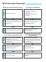
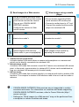

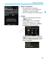
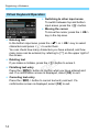
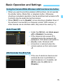
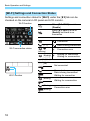


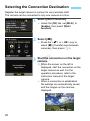
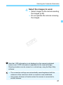
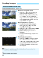
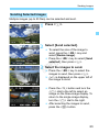
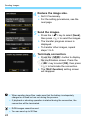
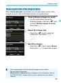
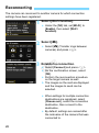
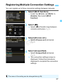

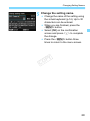

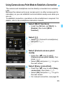
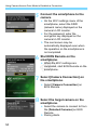
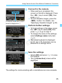
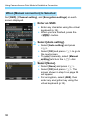
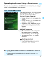
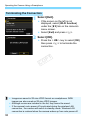

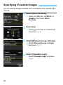
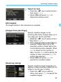
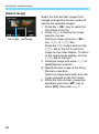
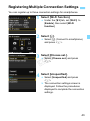


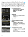
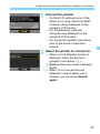
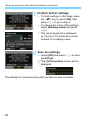

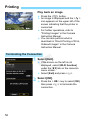


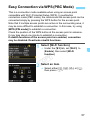
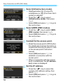
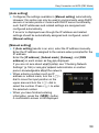
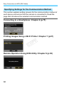
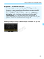
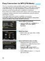
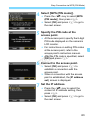
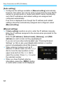


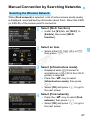
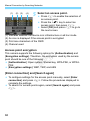
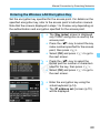
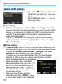
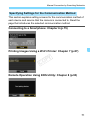
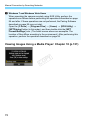


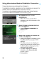
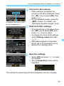
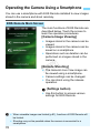
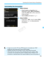
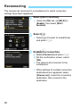
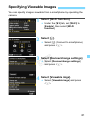

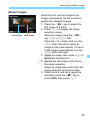
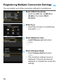


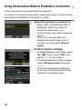
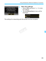

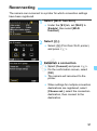
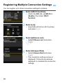


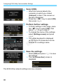

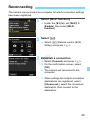
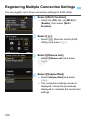


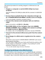

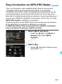


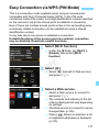
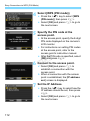
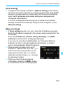
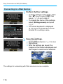
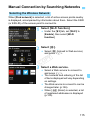

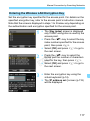

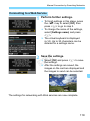
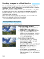
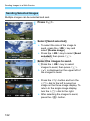


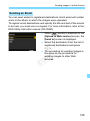

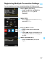


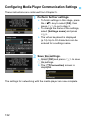
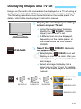
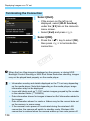
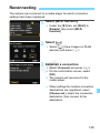
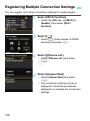


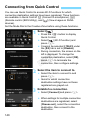
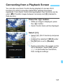
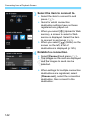


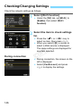
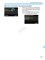

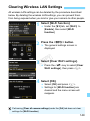


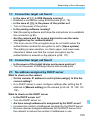


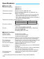


![1 Selezionare [Funzione Wi-Fi].](http://vs1.manualzilla.com/store/data/006122500_1-2575cdaa82f75317edde2332e97dcf6c-150x150.png)