1
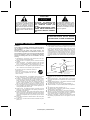
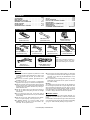
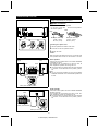
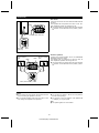
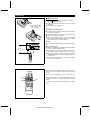
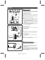
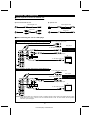
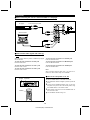
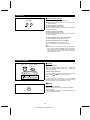
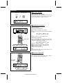
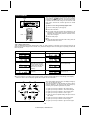
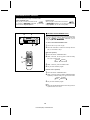
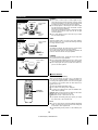
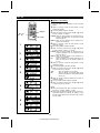
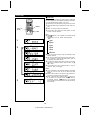
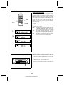
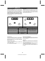
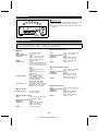
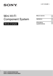
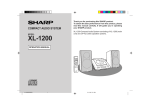
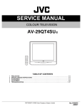
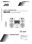
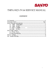
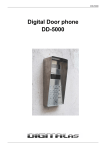
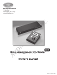
SM <P=001> MODEL HT-DD5000 HOME THEATER SYSTEM OPERATION MANUAL Thank you for purchasing this SHARP product. To obtain the best performance from this product, please read this manual carefully. It will guide you in operating your SHARP product. Note: This equipment has been tested and found to comply with the limits for a Class B digital device, pursuant to Part 15 of the FCC Rules. These limits are designed to provide reasonable protection against harmful interference in a residential installation. This equipment generates, uses, and can radiate radio frequency energy and, if not installed and used in accordance with the instructions, may cause harmful interference to radio communications. However, there is no guarantee that interference will not occur in a particular installation. If this equipment does cause harmful interference to radio or television reception, which can be determined by turning the equipment off and on, the user is encouraged to try to correct the interference by one or more of the following measures: ● Reorient or relocate the receiving antenna. ● Increase the separation between the equipment and receiver. ● Connect the equipment into an outlet on a circuit different from that to which the receiver is connected. ● Consult the dealer or an experienced radio/TV technician for help. WARNING FCC Regulations state that any unauthorized changes or modifications to this equipment not expressly approved by the manufacturer could void the user’s authority to operate this equipment. FOR YOUR RECORDS For your assistance in reporting this unit in case of loss or theft, please record below the model number and serial number which are located on the rear of the unit. Please retain this information. Model number ______________________________ Serial number_______________________________ Date of purchase ____________________________ Place of purchase ___________________________ Manufactured under license from Dolby Laboratories. "Dolby", "Pro Logic" and the double-D symbol are trademarks of Dolby Laboratories. Confidential Unpublished Works. 1992-1997 Dolby Laboratories, Inc. All rights reserved. HT-DD5000(SEC) TINSE0009SJZZ CAUTION RISK OF ELECTRIC SHOCK DO NOT OPEN The lightning flash with arrowhead symbol, within an equilateral triangle, is intended to alert the user to the presence of uninsulated "dangerous voltage" within the product’s enclosure that may be of sufficient magnitude to constitute a risk of electric shock to persons. CAU TI ON: TO REDUCE THE RISK OF ELECTRIC SHOCK, DO NO T R EMO VE CO VER (OR BACK). NO USER-SERVICEABLE PARTS INSIDE. REFER SERVICING TO QUALIFIED SERVICE PERSONNEL. The exclamation point within an equilateral triangle is intended to alert the user to the presence of important operating and maintenance (servicing) instructions in the literature accompanying the appliance. WARNING: TO REDUCE THE RISK OF FIRE OR ELECTRIC SHOCK, DO NOT EXPOSE THIS APPLIANCE TO RAIN OR MOISTURE. IMPORTANT SAFEGUARDS CAUTION All the safety and operating instructions should be read before the appliance is operated, and should be retained for future reference. Electrical energy can perform many useful functions. This unit has been engineered and manufactured to assure your personal safety. Improper use can result in potential electrical shock or fire hazards. In order not to defeat the safeguards, observe the following basic rules for its installation, use and servicing. 12 Outdoor Antenna Grounding - If an outside antenna is connected to the receiver, be sure the antenna system is grounded so as to provide some protection against voltage surges and built-up static charges. Section 810 of the National Electrical Code, ANSI/NFPA No. 70-1984, provides information with respect to proper grounding of the mast and supporting structure, grounding of the lead-in wire to an antenna discharge unit, size of grounding conductors, location of antenna-discharge unit, connection to grounding electrodes, and requirements for the grounding electrode. EXAMPLE OF ANTENNA GROUNDING AS PER NATIONAL ELECTRICAL CODE 1 Heed Warnings - All warnings on the appliance and in the operating instructions should be adhered to. 2 Follow Instructions - All operating and use instructions should be ANTENNA LEAD IN WIRE followed. 3 Water and Moisture - The appliance should not be used near water - for example, near a bathtub, washbowl, kitchen sink, laundry tub, in a wet basement, or near a swimming pool, etc. 4 Carts and Stands - The appliance should be used only with a cart or stand that is recommended by the manufacturer. G R O UN D CLAMP A N T E N NA DI SC H A RG E UNIT (NEC SECTION 810-20) ELEC TRIC SERVICE EQUIPMENT •An appliance and cart combination should be moved with care. Quick stops, excessive force, and uneven surfaces may cause the appliance and cart combination to overturn. GROUNDING CONDUCTORS (NEC SECTION 810-21) GROUND CLAMPS NEC - NATIONAL ELECTRICAL CODE S2898A P OWER SERVICE GROUNDING ELECTRODE SYSTEM (NEC ART 250, PART H) 13 Nonuse Periods - The power cord of the appliance should be 5 Wall or Ceiling Mounting - The appliance should be mounted to 6 7 8 9 10 11 a wall or ceiling only as recommended by the manufacturer. Ventilation - The appliance should be situated so that its location or position does not interfere with its proper ventilation. For example, the appliance should not be situated on a bed, sofa, rug, or similar surface that may block the ventilation openings; or, placed in a built-in installation, such as a bookcase or cabinet that may impede the flow of air through the ventilation openings. Heat - The appliance should be situated away from heat sources such as radiators, heat registers, stoves, or other appliances (including amplifiers) that produce heat. Power Sources - The appliance should be connected to a power supply only of the type described in the operating instructions or as marked on the appliance. Power-Cord Protection - Power-supply cords should be routed so that they are not likely to be walked on or pinched by items placed upon or against them, paying particular attention to cords at plugs, convenience receptacles, and the point where they exit from the appliance. Do not use liquid cleaners or aerosol cleaners. Use a damp cloth for cleaning. Power Lines - An outdoor antenna should be located away from power lines. 14 15 A B C D E 16 17 unplugged from the outlet when left unused for a long period of time. Object and Liquid Entry - Care should be taken so that objects do not fall and liquids are not spilled into the enclosure through openings. Damage Requiring Service - The appliance should be serviced by qualified service personnel when: The power-supply cord or the plug has been damaged; or Objects have fallen, or liquid has been spilled into the appliance; or The appliance has been exposed to rain; or The appliance does not appear to operate normally or exhibits a marked change in performance; or The appliance has been dropped, or the enclosure damaged. Servicing - The user should not attempt to service the appliance beyond that described in the operating instructions. All other servicing should be referred to qualified service personnel. Grounding or Polarization - Precautions should be taken so that the grounding or polarization means of an appliance is not defeated. 1 HT-DD5000(SEC) TINSE0009SJZZ CONTENTS Page ACCESSORIES . . . . . . . . . . . . . . . . . . . . . . . . . . . . . . . . . .2 PRECAUTIONS . . . . . . . . . . . . . . . . . . . . . . . . . . . . . . . . . .2 PREPARATION FOR USE . . . . . . . . . . . . . . . . . . . . . . . 3-7 EXTERNAL UNIT CONNECTION . . . . . . . . . . . . . . . . . 8-11 SOUND CONTROL . . . . . . . . . . . . . . . . . . . . . . . . . . . 11-12 DOLBY DIGITAL . . . . . . . . . . . . . . . . . . . . . . . . . . . . . . . .13 SURROUND EFFECT CONTROL . . . . . . . . . . . . . . . 14-15 Page SET UP . . . . . . . . . . . . . . . . . . . . . . . . . . . . . . . . . . . . 16-20 RADIO OPERATION . . . . . . . . . . . . . . . . . . . . . . . . . . 21-22 HOW TO USE THE BUILT-IN TIMER . . . . . . . . . . . . 23-24 HEADPHONES . . . . . . . . . . . . . . . . . . . . . . . . . . . . . . . . .24 DESCRIPTION OF TERMINOLOGY . . . . . . . . . . . . . . . .25 MAINTENANCE . . . . . . . . . . . . . . . . . . . . . . . . . . . . . . . . .26 SPECIFICATIONS . . . . . . . . . . . . . . . . . . . . . . . . . . . . . . .26 CONSUMER LIMITED WARRANTY . . . . . . . . Back cover ACCESSORIES Remote control x 1 (RRMCG0004SJSA) Front speaker wire × 2 (QCNWH0001SJZZ) FM antenna x 1 (QANTW0001SJZZ) AM loop antenna x 1 (QANTL0001SJZZ) Sub woofer wire × 1 (QCNWH0001SJZZ) Center speaker wire × 1 (QCNWH0001SJZZ) Surround speaker wire × 2 (QCNWH0002SJZZ) Note: Parts and accessories mentioned in this operation manual other than those in the drawing are not included. RCA cord x 1 (QCNWG0003SJZZ) Coaxial digital cord x 1 (QCNWG0004SJZZ) PRECAUTIONS ■ General ● Please ensure that the equipment is positioned in a well ventilated area and ensure that there is at least 4" (10 cm) of free space along the sides, top and back of the equipment. ● Do not use oil, solvents, gasoline, paint thinners or insecticides on the unit. ● Do not expose the unit to moisture, to temperatures higher than 140˚F (60˚C) or to extreme low temperatures. ● Keep the unit away from direct sunlight, strong magnetic fields, excessive dust, humidity and electronic/electrical equipment (home computers, facsimiles, etc.) which generates electrical noise. ● Hold the AC power plug by the head when removing it from the AC outlet, since pulling the cord can damage internal wires. ● Do not remove the outer cover, as this may result in electric shock. Refer internal service to your local SHARP service facility. ● Use the unit on a firm, level surface free from vibration, and do not place anything on the top of the unit. ● If "ERROR" appears or no sound is heard, set the POWER button on the main unit to OFF. About 5 seconds later, turn the power back on. ● If the unit does not work properly while in use, disconnect the AC power cord from the AC outlet. Plug the AC power cord back in, and then set the POWER button on the main unit to ON. ● If an electrical storm is taking place near you, it is suggested that you disconnect the AC power cord from the AC outlet for safety. Warning: The voltage used must be the same as that specified on this unit. Using this product with a higher voltage other than which is specified is dangerous and may result in a fire or other type of accident causing damage. SHARP will not be held responsible for any damage resulting from use of this unit with a voltage other than that which is specified. ■ Volume control The sound level at a given volume setting depends on a combination of speaker efficiency, location and various other factors. It is advisable to avoid exposure to high volume levels, which occur while turning the unit on with the volume control setting up high, or while continually listening at high volumes. 2 HT-DD5000(SEC) TINSE0009SJZZ PREPARATION FOR USE Unplug the AC power cord from the AC outlet before connecting or disconnecting any component. ■ Speaker connection Wires to be used with each speaker For the front, center and For the surround speakers sub woofer speakers Black Black 3 2 1 Black (with white line) Length: Approx. 98-7/16" (2.5 m) Black (with white line) L en gth : App ro x. 393-3/4" (10 m) Connecting the speaker wires 1 2 3 Hold the speaker wire release catch down. Insert the wire into the speaker terminal. Release the catch. Caution: When connecting the speakers to the unit, connect the wires to the speakers first, and then to the terminals on the unit. Black Front speakers Front speaker (Left) Front speaker (Right) Connect each front speaker wire to the FRONT SPEAKER A terminals as shown. Use speakers with an impedance of 8 ohms or more, as lower impedance speakers can damage the unit. ● Connect the black wire with the white line to the negative (–) terminal, and the black wire to the positive (+) terminal. Black Note: ● You can connect the speakers you have to the FRONT SPEAKER B terminals. The recommended impedance is 8 ohms. Black (with white line) Black (with white lline) Black Center speaker Connect the center speaker wire to the CENTER SPEAKER terminals as shown. Use a speaker with an impedance of 8 ohms or more, as a lower impedance speaker can damage the unit. ● Connect the black wire with the white line to the negative (–) terminal, and the black wire to the positive (+) terminal. Black Black (with white lline) Black (with white lline) Black 3 HT-DD5000(SEC) TINSE0009SJZZ (Continued) Sub woofer Connect the sub woofer wire to the SUB WOOFER terminals as shown. Use a speaker with an impedance of 8 ohms or more, as a lower impedance speaker can damage the unit. ● Connect the black wire with the white line to the negative (–) terminal, and the black wire to the positive (+) terminal. Black Black (with white line) Black (with white line) Black Surround speakers Surround speaker (Right) Black Black Connect each surround speaker wire to the SURROUND SPEAKER terminals as shown. Use speakers with an impedance of 8 ohms or more, as lower impedance speakers can damage the unit. ● Connect the black wire with the white line to the negative (–) terminal, and the black wire to the positive (+) terminal. Surround speaker (Left) Black (with white line) Black (with white line) Black Caution: ● Do not reverse the right channel and left channel wires when connecting the speakers to the unit. ● Do not let bare speaker wires touch each other, as this may damage the amplifier and/or speakers. ● Do not allow any objects to fall into or to be placed in the bass reflex openings. ● Do not stand or sit on the speakers. If the speakers fall or collapse, you may be injured. Note: ● The speaker grilles are not removable. 4 HT-DD5000(SEC) TINSE0009SJZZ (Continued) ■ Placing the speakers Center Front left Front right When you connect this unit to a DVD player playing a disc with the trademark, you can enjoy realistic, powerful sound by playing the soundtrack through 6 channels; the front left, front right, center, surround left, surround right and sub woofer speakers. Sub woofer The best sound will be achieved by placing each speaker the same distance from the listener. Arrange the speakers so that the layout is as close as possible to the diagram shown in this illustration. Surround left ● Front speakers Surround right Same distance For best performance, place the speakers as shown in the diagram to the left. Place a TV halfway between the front left and front right speakers. Front right Front left ● Center speaker Center It is recommended that the center speaker be placed between the left and right front speakers. Example: When installed on the wall ● Sub woofer Surround speaker Place the sub woofer near one of the front speakers, and orient it toward the listener as much as possible. Wall ● Surround speakers 23" - 35" (60 - 90 cm) The surround speakers can be used by installing them on the wall or on stands. Install them 23" - 35" (60 - 90 cm) above the height of your ears when seated, if possible. Example: When installed vertically Note: The front speakers, center speaker, and sub woofer are magnetically shielded. The front speakers and sub woofer may be used by the sides of the TV. The center speaker may be used on top of the TV. However, some color variation may occur, depending on the type of TV used. 5/32" (3.8 mm) If color variations occur .... Turn off the TV (from the power switch). After 15 - 30 minutes, turn the TV on again. If the color variation is still present .... Move the speakers further away from the TV. 3/32" (2.7 mm) ■ To mount the surround speakers on the Min. 9-27/32" (25 mm) 9/32" (7 mm) 1 Min. 8-1/4" (21 mm) wall 5/32" (4 mm) The design of the surround speakers allows them to be hung on the wall. Be sure to use the screw type and size shown to the left. Wall mounting screw 1 Wall surface Drive one screw into the wall for each speaker as shown in the illustration. ● Make sure that both the screw and the wall can support a load of 45 lbs. (20 kg). ● Drive the screws, so there is about a 5/32" (4 mm) space between the wall and the head of the screw. ● The screw is not included. 2 2 Wall surface Mount the surround speaker on the wall so that the screw head is inserted into the slot on the surround speaker. 5 HT-DD5000(SEC) TINSE0009SJZZ (Continued) ■ Remote control ● When inserting or removing the batteries, push them toward the battery terminal. ● Installing the batteries incorrectly may cause the unit to malfunction. ● The batteries are not included. ë ● 2 "AA" size batteries (U M / SU M- 3 , R6 , HP-7 or similar) Precautions for battery use: ● Insert the batteries according to the direction indicated in the battery compartment. ● Replace all old batteries with new ones at the same time. ● Do not mix old and new batteries. ● Remove the batteries if they are weak or if the unit will not be used for long periods of time. This will prevent potential damage due to battery leakage. + + - Caution: Do not use rechargeable batteries (nickel-cadmium battery, etc.). 15˚ Notes concerning use: ● Replace the batteries if the operating distance is reduced or if the operation becomes erratic. ● Periodically clean the transmitter LED on the remote control and the sensor on the main unit with a soft cloth. ● Exposing the sensor on the main unit to strong light may interfere with operation. Change the lighting or the direction of the unit. ● Keep the remote control away from moisture, excessive heat, shock, and vibrations. (A) (B)(C) SHARP TVs, VCRs and DVDs which are equipped with remote control can be controlled with button groups (A), (B) and (C). 8" - 20’ (0.2 m - 6 m) 15˚ Some TV and VCR models may not have some functions. Please refer to the TV’s, VCR’s and DVD’s operation manual. The remote control may not funciton with some TV and VCR models. (A) (B) (C) For details consult your nearest SHARP dealer or service center. 6 HT-DD5000(SEC) TINSE0009SJZZ (Continued) ■ Antenna connection 1 3 2 Supplied FM antenna Connect the FM antenna wire to the FM 75 OHMS terminal and position the FM antenna wire in the direction where the strongest signal can be received. AM loop antenna 1 Outdoor FM antenna 2 Supplied AM loop antenna FM antenna Connect the AM loop antenna wire to the AM and GND terminals. Position the AM loop antenna for optimum reception. Place the AM loop antenna on a shelf, etc., or attach it to a stand or wall with screws (not supplied). Notes: ● If you still hear static even after adjusting the position of the AM loop antenna, try reversing the wires or turn off the power to any external unit not in use. ● Do not place the antenna wires on the unit. It may result in noise generation, since the unit is equipped with digital electronics. Place the AM loop antenna and the FM antenna wire away from the unit for better reception. ● If the antenna wires are placed near the AC power cord, they may cause interference. 3 49 feet (15 m) Outdoor AM antenna Outdoor FM antenna Use an outdoor FM antenna (75 ohm coaxial cable) if you require better reception. Consult your dealer. 25 feet (7.5 m) Note: When an outdoor FM antenna is used, disconnect the supplied FM antenna wire from the FM 75 OHMS terminal. Ground rod Outdoor AM antenna Use an outdoor AM antenna if you need better reception. Consult your dealer. 75 ohm coaxial cable Note: When using an outdoor AM antenna, be sure to keep the wire of the AM loop antenna connected. Ground wire ■ Connecting the AC power cord After connecting the speakers and antennas, plug the AC power cord into a convenient AC outlet. AC OUTLET Note: ● Unplug the AC power cord from the AC outlet if the unit will not be in use for a prolonged period of time. AC 120 V, 60 Hz Unswitched AC Outlet Used to plug in the AC power plug from other equipment. The power consumption of any units connected to this outlet should not exceed a total of 120 W. The power to any equipment connected to this outlet is not switched by the POWER switch on the HT-DD5000. To an AC outlet 7 HT-DD5000(SEC) TINSE0009SJZZ EXTERNAL UNIT CONNECTION ■ Cords required to connect an external unit The following cords are available to connect an external unit. ● Cord included with this unit ● Optional cord Coaxial digital cord Optical digital cable RCA cord Video cord ■ When connecting the unit to a DVD player When connecting an audio signal using an optical digital cable To the audio (line) output jacks DVD player To the video output jack To the audio (digital) output jack TV To the video input jack When connecting an audio signal using a coaxial digital cord To the audio (line) output jacks DVD player To the video output jack To the audio (digital) output jack TV To the video input jack Caution: A DVD player allows you to select the "PCM" or "DOLBY DIGITAL" audio output mode. Before playing a Dolby digital sound disc, be sure to set the unit in the "DOLBY DIGITAL" mode. For more details, see the operation manual for your DVD player. 8 HT-DD5000(SEC) TINSE0009SJZZ (Continued) ■ When connecting the unit to a VCR or a camcorder To the audio output jacks VCR To the audio input jacks TV To the video output jack To the video input jack To the video input jack Camcorder To the audio output jacks VCR To the video output jack ■ When connecting the unit to a tape deck or an MD deck To the audio output jacks MD deck To the audio input jacks 9 HT-DD5000(SEC) TINSE0009SJZZ (Continued) ■ When connecting the unit to a stereo turntable or a CD player CD player To the audio output jacks Stereo turntable ■ How to switch audio signals and video signals When the function button is pressed, a different input signal can be selected. To select the unit connected to the CD/AUX jacks Press the CD/AUX button. To select the unit connected to the DVD jacks Press the DVD button. To select the unit connected to the MD/TAPE jacks Press the MD/TAPE button. To select the unit connected to the VCR 1 jacks Press the VCR 1 button. To select the unit connected to the PHONO jacks Press the PHONO button. To select the unit connected to the VCR 2 jacks Press the VCR 2 button. Note: When a function other than DVD, VCR 1 or VCR 2 is selected, the video monitor output is not available. ■ How to turn the power on or off POWER STAND-BY 1 Set the POWER button on the main unit to ON. ● The STAND-BY indicator will light up and the power will be on. 2 3 POWER As long as the STAND-BY indicator is lit, you can turn the power on or put the unit in the stand-by mode, using the POWER button on the remote control. When through using this unit, set the POWER button on the main unit to OFF. ● The STAND-BY indicator will go out. 10 HT-DD5000(SEC) TINSE0009SJZZ (Continued) ■ Front speaker selector SPEAKERS A B ● Select the front speakers you want to use. ● Before selecting the switches, be sure to set the VOLUME control to 0. OFF To listen using the "A" speakers: Set the SPEAKERS A button to ON. ● Sound will also be heard from the center, sub woofer and surround speakers. ON To listen using the "B" speakers: Set the SPEAKERS B button to ON. ● No sound will be heard from the center, sub woofer or surround speakers. To listen using both the "A" and "B" speakers: Set the SPEAKERS A and B buttons to ON. To stop the sound from all of the speakers: Set the SPEAKERS A and B buttons to OFF. ● To use headphones, set both buttons to OFF. Note: ● If either pair of the speakers, A or B, are connected to this unit, when both the SPEAKER A and B buttons are select to ON, no sound will be heard from the front speakers. Set the button for the speakers which you have connected to this unit to ON. SOUND CONTROL ■ Volume (Main unit) (Remote control) (Main unit operation) VOLUME When the VOLUME control is held in the + position, the volume will increase. When it is held in the − position, the volume will decrease. VOLUME 0 1 2 79 (Remote control operation) 80 Press the VOLUME button to increase the volume and the VOLUME button to decrease the volume. Note: If you were listening at a volume of "71" or louder before turning the power off, when the power is turned on next time, the volume will be set back automatically to "70". ■ Muting (Remote control operation) MUTE Press the MUTE button to mute the sound immediately. "MUTE" will flash. Press the MUTE button again to switch the sound back up to its previous volume level. 11 HT-DD5000(SEC) TINSE0009SJZZ (Continued) (Main unit) ■ Extra bass (X-BASS) (Remote control) (Main unit/remote control operation) X-BASS Press the X-BASS button to emphasize the bass region of the frequency spectrum. To cancel the extra bass mode, press the X-BASS button. "X-BASS" will go out. X-BASS ■ Pre-programmed equalizer 1 (Main unit operation) 1 Press the EQUALIZER button. ● The current mode setting will be displayed. 2 2 Within 3 seconds, turn the jog dial to change to a different mode. FLAT HEAVY 1 HEAVY 2 SOFT 2 SOFT 1 3 3 Within 5 seconds, press the ENTER button. (Remote control operation) When the EQUALIZER button is pressed, the current mode setting will be displayed. To change to a different mode, press the EQUALIZER button repeatedly. EQUALIZER FLAT HEAVY 1 HEAVY 2 SOFT 2 SOFT 1 FLAT: The sound is not modified. HEAVY 1: Bass and treble are slightly emphasized. HEAVY 2: Bass and treble are emphasized more. SOFT 1: Treble is cut a little. SOFT 2: Treble is reduced a lot. FLAT HEAVY 1 HEAVY 2 SOFT 2 SOFT 1 Note: When the equalizer mode is being used, the Dolby Pro Logic Surround mode is canceled. ■ Sub woofer output level (Remote control operation) W X When the SUB WOOFER LEVEL ( / ) button is pressed, the sub woofer output level can be changed. XW SUB WOOFER LEVEL ( ) -10 9 +9 +10 12 HT-DD5000(SEC) TINSE0009SJZZ DOLBY DIGITAL When you connect this unit to a DVD player which is playing a disc with the trademark, you can enjoy realistic, powerful sound by playing back the recorded signal through 6 speakers with the sound coming from the front left, front right, center, surround left, surround right and sub woofer speakers. DVD To listen to a disc using the Dolby Digital mode: 1 2 Connect a DVD player. (See page 8.) Press the DVD button. ● The current DVD input channel will be displayed. If the DVD button is pressed while the current DVD channel is displayed, the input channel (ANALOG, COAXIAL, OPTICAL) can be changed. DVD 3 Start the DVD player. Note: ● When the Dolby Digital surround mode is being used, the equalizer will be set to FLAT. Type of Dolby digital signal There are different types of Dolby digital signals. When you select COAXIAL or OPTICAL for the DVD input channel, the following items will be displayed for 2 seconds. They will also be displayed when the DVD player is operating and the DVD button is pressed. Display Channels available DIGITAL Display Normal PCM playback DIGITAL Center only (monaural) DIGITAL Front (L, R) (When the surround mode is set to Normal, Phantom or Wide sound will also be heard from the surround speakers.) DIGITAL Front (L, R) + surround (L, R) Front (L, R) + center Front (L, R) + center + surround (monaural) DIGITAL Front (L, R) + surround (monaural) DIGITAL Channels available DIGITAL Front (L, R) + center + surround (L, R) ● If a low frequency sound effect (Low Frequency Effect) contains a Dolby digital signal, "LFE" will light in the display. When this "LFE" is lit, low frequency signals will be output from the sub woofer. ➁ ➀ When Dolby digital signals are input, the display will light up or go out, as shown to the left. The channel speaker and SW indicators are used to set the sound for listening in the surround mode and will light up according to the speaker signals that are present. ➂ ➀ ➁ ➂ ➃ ➄ Lights up if the Lights up if the Lights up if the Lights up if the Lights up when sub woofer. ➅ Lights up if the ➆ Lights up if the ➇ Lights up if the ➄ ➃ ➅ ➆ ➇ 13 HT-DD5000(SEC) TINSE0009SJZZ input contains a left channel signal. input contains a center channel signal. input contains a right channel signal. input contains an "LFE" signal. the amplifier setting will output sound to input contains a left surround signal. input contains surround signals. input contains a right surround signal. SURROUND EFFECT CONTROL This product allows you to enjoy 3 surround modes. Normal mode/Wide mode: When you play a sound source that has the (5.1 channels) or trademarks, you can enjoy surround sound using all 6 speakers. 2 Phantom mode: When you play a sound source that has the or trademarks, you can enjoy surround sound using 5 speakers, but not the center speaker. ■ NORMAL/PHANTOM/WIDE mode 3 When you connect this unit to other equipment (DVD player, LD player, video etc.) which is playing sound sources that have the or trademarks, you can enjoy Dolby surround sound. To listen to Normal/Phantom/Wide mode: 4 5 1 2 Connect the unit you want to play. Press the DVD button to select the DVD input from the jack you connected in step 1. (Main unit operation) 3 4 2 Press the DOLBY SURROUND button. Within 3 seconds, turn the jog dial to select the Dolby Pro Logic Surround mode. STEREO NORMAL WIDE PHANTOM 3 5 6 Within 5 seconds, press the ENTER button. Play the video software program. (Remote control operation) 3 4 Press the DOLBY SURROUND button. Within 3 seconds, press the DOLBY SURROUND button repeatedly to select the Dolby Pro Logic Surround mode. STEREO NORMAL WIDE PHANTOM 5 Play the video software program. Note: ● When the Normal/Phantom/Wide mode is being used, the equalizer will be set to FLAT. 14 HT-DD5000(SEC) TINSE0009SJZZ (Continued) NORMAL: NORMAL/WIDE ● For a stereo 2 channel input or a Dolby digital 2/0 input, sound will be output from the front left, front right, center and surround speakers. The same monaural channel will be output from the left and right surround speakers. ● For a Dolby digital 5.1 channel input, sound will be output from the front left, front right, center, sub woofer, surround left and surround right speakers. If the surround signal only contains 1 channel, the same monaural channel will be output from the left and right surround speakers. ● For a Dolby digital 1/0 input, sound will only be output from the center speaker. Center speaker Front speaker (Left) Front speaker (Right) Sub woofer Surround (Left) Surround (Right) WIDE: PHANTOM Front speaker (Left) Select the WIDE mode if you have a large center speaker. With the WIDE mode, you can take full advantage of Dolby Pro Logic Surround sound. Front speaker (Right) PHANTOM: Sub woofer Surround (Left) The difference between this mode and the normal mode is that no sound is output from the center speaker. The center speaker signal is split equally and added to the sound for the front left and front right speakers. Surround (Right) STEREO: Cancel the surround mode. Sound will only be output from the front left and front right speakers. ● For a Dolby digital multichannel input, any center or rear signals will be mixed and output from the front speakers. ● For a Dolby digital 1/0 input, monaural sound will be output from the front speakers. STEREO Front speaker (Left) Front speaker (Right) Sub woofer ■ Preset balance (Remote control operation) While you are listening to music in any of the Dolby Pro Logic Surround modes (NORMAL, PHANTOM, WIDE), you can change the apparent position of the sound coming from the speakers to any position which has been stored in the memory of this unit. 1 Press the PRESET BALANCE button. ● The current mode setting will be displayed. 2 PRESET BALANCE To change to a different mode, press the PRESET BALANCE button repeatedly. CENTER: More pronounced sound is heard from the center. BACK: More sound is heard from the rear. FRONT: More sound is heard from the front. 3 The speaker level setting (see page 18) lets you change the center level or the surround level. Notes: ● If you turn off the power or press the PRESET BALANCE button, the center level or the surround level settings will be returned to their original levels. ● The initial setting of this product is in the CENTER position. 15 HT-DD5000(SEC) TINSE0009SJZZ SET UP ■ Speaker size setting 1 2 3 SET UP 1 4 DIGITAL 5 DIGITAL 6 Within 10 seconds, press the ITEM button to make "SURR-SP" appear. ● The surround speaker indicators will flash. DIGITAL 7 2 seconds 5 Within 10 seconds, press the SET UP ( to select "SP-YES" or "SP-NO". YES: NO: DIGITAL DIGITAL 8 9 6 7 DIGITAL DIGITAL Within 10 seconds, press the ITEM button to make "SWOOFER" appear. Within 10 seconds, press the SET UP ( to select "SP-YES" or "SP-NO". DIGITAL 2 seconds 9 When the speakers are connected When no speaker is connected (When NO is selected, the indicator for that speaker position will go out.) W or X) button Notes: ● When all 6 speakers have been connected, set each of the items to "LARGE", "SMALL" or "YES". ● When using the speakers included with this unit, the recommended speaker size settings are "SMALL" for the front and center speakers and "SP-YES" for the surround and sub woofer. 2 seconds 8 W or X) button ● The sub woofer speaker indicators will flash. DIGITAL DIGITAL W X) button Within 10 seconds, press the SET UP ( or to select "LARGE", "SMALL" or "SP-NO". LARGE: When the center speaker can reproduce low frequencies (speakers which can reproduce sounds lower than 60 Hz) SMALL: When the center speaker cannot reproduce extremely low frequencies NO: When no speaker is connected (When NO is selected, the indicator for that speaker position will go out.) DIGITAL DIGITAL 4 W or X) button Within 10 seconds, press the ITEM button to make "CENT-SP" appear. ● The center speaker indicators will flash. 2 seconds 3 Within 10 seconds, press the SET UP ( to select "LARGE" or "SMALL". LARGE: When the front speakers can reproduce low frequencies (speakers which can reproduce sounds lower than 60 Hz) SMALL: When the front speakers cannot reproduce extremely low frequencies ITEM DIGITAL 2 Within 10 seconds, press the ITEM button to make "FRONT-SP" appear. ● The front speaker indicators will flash. MENU X W Press the MENU button repeatedly to make "SP SIZE" appear. DIGITAL DIGITAL 16 HT-DD5000(SEC) TINSE0009SJZZ (Continued) ■ Speaker delay setting The best sound will be achieved by placing the front speakers, center speaker and surround speakers at the same distance from the listener. When some of the speakers are at a different distance from the listener, you can select a speaker delay to make it seem as though the speaker distances are the same. (Factory-shipped settings: CENTER → 0 ms, SURROUND → 5 ms) If the settings need to be changed due to the type of sound source being played or the conditions in the room, change them as follows. MENU XW SET UP ITEM 1 2 1 DIGITAL Press the MENU button repeatedly to make "SP DELAY" appear. Within 10 seconds, press the ITEM button to select "CENT-SP" or "SURR-SP". CENT-SP: To delay the sound from the center speaker SURR-SP: To delay the sound from the surround speakers ● The selected speaker indicator(s) will flash. 2 DIGITAL 3 DIGITAL 3 Adjustable range CENTER: 0 ms - 5 ms SURROUND: 0 ms - 15 ms (When the DIGITAL indicator is lit) 15 ms - 30 ms (When the DIGITAL indicator is not lit) (Can be changed in 1 ms steps.) mS 0 2 DIGITAL 3 DIGITAL 1 4 5 Notes: ● As a guide for setting the correct delay time, 1 ms is equal to approximately 12" (30 cm) from where the selected speakers are placed further away from the listener than the typical location. ● If the delay time for the surround speakers is set to a large value, a large sound space will be created. If it is set to a small value, the sound space will be small and intimate. mS 0 1 14 W or X) button Within 10 seconds, press the SET UP ( to select a value. 15 17 HT-DD5000(SEC) TINSE0009SJZZ (Continued) ■ Front speaker balance adjustment You can adjust the balance between the left and right channels of the front speakers. 1 2 MENU X W SET UP Press the MENU button repeatedly to make "SP LEVEL" appear. Within 10 seconds, press the ITEM button to make "F-SP CEN" appear. ● The front speaker indicators will flash. 3 ITEM W W X DIGITAL 1 2 3 X Within 10 seconds, pressing the SET UP button will increase the right speaker level (the left speaker level will decrease), or pressing the SET UP button will increase the left speaker level (the right speaker level will decrease). ● If the SET UP ( or ) button is held down, the speaker level can be changed continuously. ● The speaker balance, as shown in the display, can be changed within a range of "1" to "20". DIGITAL Note: The surround speaker balance will not be changed. W X) button to make "F-SP To balance the front speaker(s): In step 3, press the SET UP ( or CEN" appear. DIGITAL 1 2 9 20 DIGITAL 1 ■ Speaker level setting 2 9 The output level of the center, surround or sub woofer speakers can be adjusted. 20 1 2 1 DIGITAL 2 DIGITAL Press the MENU button repeatedly to make "SP LEVEL" appear. Within 10 seconds, press the ITEM button repeatedly to select the speaker (CENT, RSUR, LSUR or SWFR) you want to adjust. ● The selected speaker indicator will flash. Note: ● While DIGITAL is lit, "RSUR" and "LSUR" will be displayed. If DIGITAL is not lit, "SURR" will be displayed. dB DIGITAL dB 3 DIGITAL Within 10 seconds, press the SET UP ( to adjust the output level. W or X) button ● You can change the level within a range of +10dB to -10dB, in 1dB steps. ● While DIGITAL is lit, the left and right speaker levels can be adjusted independently by displaying "RSUR" and "LSUR". However, if DIGITAL is not lit, "SURR 0dB" will be displayed, and both channels will be adjusted at the same time. dB DIGITAL dB 18 HT-DD5000(SEC) TINSE0009SJZZ (Continued) ■ Test tone You can check (and adjust) the speaker level by listening to the sound output from each speaker individually, while standing at the actual listening position in the room. The speaker level can be adjusted using the remote control. 1 MENU X W 2 SET UP Press the MENU button repeatedly to make "TEST" appear. Within 10 seconds, press the ITEM button. ● The test tone will be heard from each speaker, in order, at about 5 second intervals. ITEM Note: ● While DIGITAL is lit, "R-SURR" and "L-SURR" will be displayed. If DIGITAL is not lit, "SURR" will be displayed. 1 DIGITAL L-FRNT ↓ CENTER ↓ R-FRNT ↓ R-SURR ↓ L-SURR ↓ S-WOOFER DIGITAL 2 DIGITAL ● When the test tone is being output, the indicator for that speaker will flash. ● The test tone will be heard until the current menu selection is changed by pressing the MENU button again, or by selecting some other function. DIGITAL 3 DIGITAL W To adjust the speaker level while the test tone is being output from a particular speaker, press the SET UP ( or ) button. X ● The speaker level can be adjusted within a range of +10dB to -10dB, in 1dB steps. DIGITAL Notes: ● If "NO" is selected for any individual speaker’s size setting (page 16), the test tone will not be heard from that speaker. ● Please note that the front left and front right speaker levels cannot be adjusted using this method. ● When a surround test is performed while DIGITAL is lit, "R-SURR" and "L-SURR" will be displayed and can be adjusted. However, if DIGITAL is not lit, "SURR" will be displayed, and both channels will be adjusted at the same time. DIGITAL 3 DIGITAL 19 HT-DD5000(SEC) TINSE0009SJZZ (Continued) ■ Dynamic range setting DVD discs have a wider dynamic range (sound volume range) than existing VHS videotapes or CD discs. If they are played in home systems, there may be too much difference between the loud and quiet sounds. Therefore, if the volume is set so that the quiet sounds can be heard clearly, the loud sounds may be far too loud. On the other hand, if the volume is set so that the loud sounds are not too loud, you may not be able to hear the quiet sounds. Three settings are available to control the dynamic range easily. MENU XW SET UP 1 ITEM 2 Press the MENU button repeatedly to make "D-RANGE" appear. Within 10 seconds, press the ITEM button to select "MAX", "STD" or "MIN". MAX: 1 DIGITAL STD: MIN: 2 This setting does not compress the dynamic range of the Dolby digital signal, allowing you to enjoy the full, powerful sound of Dolby encoded digital signals. This setting compresses the dynamic range, and may produce a more appropriate volume range for home use. This setting compresses the dynamic range, allowing you to enjoy movies at a lower volume. DIGITAL DIGITAL DIGITAL Returning various surround settings to their default condition: 1 1 2 Hold down the DOLBY SURROUND button on the main unit until "CLEAR" appears. Within 5 seconds, press the ENTER button. ● As shown on the setup menu, any of the settings that have been changed will be returned to their factory default settings. 2 20 HT-DD5000(SEC) TINSE0009SJZZ RADIO OPERATION ■ Tuning 1 1 2 3 4 2,3,5,6 4 Set the POWER button on the main unit to ON. Press the TUNER (BAND) button. Press the TUNER (BAND) button again to select the desired frequency band. (FM ST, FM or AM) Press the TUNING (UP or DOWN) button to tune into the desired station. Manual tuning: Press the TUNING (UP or DOWN) button as many times as required to adjust the frequency shown in the display to the frequency of the desired station. Auto tuning: When the TUNING (UP or DOWN) button is pressed for more than 0.5 seconds, scanning will start automatically and the tuner will stop at the first receivable broadcast station. Notes: ● When radio interference occurs during auto scan tuning, auto scan tuning may stop automatically at that point. ● If a weak station signal is found during auto scan tuning, the station will be skipped. ● To stop auto tuning, press the TUNING (UP or DOWN) button again. 5 To receive an FM stereo transmission, press the TUNER (BAND) button so that the "STEREO" indicator on the display lights up. ● " 6 j" will appear when an FM broadcast is in stereo. If the FM reception is weak, press the TUNER (BAND) button so that the "STEREO" indicator goes out. ● Although the reception changes to monaural, the sound becomes clearer. After use: Set the POWER button on the main unit to OFF. Notes: ● The last station tuned in will be recalled, even after changing the tuning band or the function, or after turning the power off. ● When listening to a radio station broadcasting monaural sound, select STEREO in the Dolby Surround mode. 21 HT-DD5000(SEC) TINSE0009SJZZ (Continued) ■ Preset tuning You can store up to 40 stations in memory (40 stations consisting of any combination of FM and AM stations you like) and recall them at the push of a button. To enter stations into memory: 1 2 Perform steps 1 - 6 in the "Tuning" section. Press the MEMORY button. ● "MEMORY" will flash. 3 Within 5 seconds, turn the jog dial to make the preset channel number flash in the display. ● Store the stations in memory, in order, starting with preset channel 1. 2 3 4 4 Within 5 seconds, press the ENTER button to store that station in the selected station preset number memory. ● If the "MEMORY" and preset number indicators go out before the station is memorized, repeat the operation from step 2. 5 Repeat steps 1 - 4 to set other preset stations, or to change a preset station. To recall a memorized station: X W Turn the jog dial on the main unit or press the PRESET ( or ) button on the remote control for less than 0.5 seconds to select the desired station. ● The stations (preset channel number, frequency and frequency band) which have been stored in memory will appear in the display in numerical order, irrespective of the frequency bands. Note: When searching for a memorized station, do not press the PRESET button for more than 0,5 seconds. When the PRESET button is pressed for more than 0,5 seconds, the unit will enter the preset memory scan mode. Backup function: The backup function protects all station presets for a few hours should there be a power failure or the AC power cord is removed from the AC outlet. ■ Preset memory scan The stations saved in the preset memory can be scanned automatically. 1 X PRESET W To scan the preset stations, press the PRESET ( button for more than 0,5 seconds. X or W) ● The station preset number will flash and the programmed stations will be tuned in sequentially, for 5 seconds each. 2 X W Press the PRESET ( or ) button again to stop the memory scan at the desired station. Note: When the preset memory does not have any stations stored in it, the preset memory scan will not function. To erase the contents in the preset memory: 1 2 3 Select the preset channel number you want to erase. Hold down the MEMORY button until "CLR" appears. Within 5 seconds, press the ENTER button. ● After performing this operation, the preset memory information will be erased. 22 HT-DD5000(SEC) TINSE0009SJZZ HOW TO USE THE BUILT-IN TIMER ■ Timer playback 1 ● Timer operation is only possible when the TUNER function is selected. TIMER 1 2 Set the POWER button on the main unit to ON. Press the TUNER (BAND) button. ● Tune in the desired station. 3 2 3 4 4 5 Press the TIMER/SLEEP button repeatedly until "TIMER" is displayed. Turn the jog dial to select how many hours from now you want to start timer playback. ● The maximum time that you can specify is 12 hours, in 15-minute intervals. OFF ↔ 0:15 ↔ 0:30 ....... 11:45 ↔ 12:00 3 5 Press the ENTER button. ● After the timer setting has been displayed for 2 seconds, the tuner band and station will be displayed. ● The TIMER indicator will light up. The unit will enter the timer stand-by mode. 4 6 7 Adjust the volume level. Press the POWER button on the remote control to turn the power off. Note: ● When you set the POWER button on the main unit to OFF, the main power will be turned off, and timer playback will not work. 8 7 When the timer start time is reached, timer playback will start. ● The volume will increase gradually until it reaches the volume you were listening to before turning off the unit. ● Even if you selected a different function other than the tuner before turning off the power, the tuner will be selected. 9 The power will be turned off one hour after the timer has started. ● When it is one minute before the timer-off time, the volume will start to fade. To check the timer setting (when in the timer playback stand-by mode): Press the TIMER/SLEEP button once. ● The remaining operation time will be displayed for 2 seconds. Then the tuner band and station will be displayed for 2 seconds. To cancel the timer operation: Press the POWER button to turn the power on. To resume timer playback: To set timer playback again after a timer playback operation has finished, perform steps 1 - 7 above. ● The timer playback setting time will be canceled after a timer playback operation has finished. 23 HT-DD5000(SEC) TINSE0009SJZZ (Continued) ■ Sleep operation The tuner and any components that are connected to the DVD, VCR-1, VCR-2, CD/AUX, MD/TAPE or PHONO jacks can be turned off automatically. 1 2 3 1 2 3 4 Play back the desired sound source. Press the TIMER/SLEEP button repeatedly until "SLEEP" is displayed. Turn the jog dial to set the sleep time. ● The maximum sleep time you can specify is 2 hours, in 5-minute intervals. OFF ↔ 5 ↔ 10 ............ 1:55 ↔ 2:00 4 5 2 Press the ENTER button. The unit will turn off automatically after the preset sleep time has elapsed. ● When it is one minute before the sleep-off time, the volume will start to fade. 3 To check the remaining sleep time: Press the TIMER/SLEEP button twice. To cancel the sleep operation: Press the POWER button to turn the power off. Notes: ● After the sleep operation has finished, the sleep setting time will be canceled. If you want to set the sleep operation again, start from the beginning of this procedure. ● The sleep operation cannot control any components that are connected to the DVD, VCR-1, VCR-2, CD/AUX, MD/TAPE or PHONO jacks. HEADPHONES ● Before plugging in or unplugging the headphones, make sure the volume level is reduced. ● Be sure your headphones have a 1/4" (6.3 mm) diameter plug and are between 16 ohms and 50 ohms impedance. The recommended impedance is 32 ohms. 1 2 Set the SPEAKERS A and B button to OFF. When headphones are connected, adjust the VOLUME control for the desired volume. Note: ● When using headphones, it is recommended that you select STEREO in the Dolby Surround mode. 24 HT-DD5000(SEC) TINSE0009SJZZ DESCRIPTION OF TERMINOLOGY Dolby Pro Logic Surround: This refers to the Dolby Surround sound decoder system which is used for movies. Using 4 channels, the sound effects, dialog, sound direction, music, etc. are all reproduced more realistically. Dolby Pro Logic Surround makes the location and movement of sounds much more natural than the original Dolby Surround system. You can enjoy a realistic, powerful feeling like being at a live performance or as if you were at a movie theater or in a concert hall. In order to enjoy this effect, you need at least one pair of surround speakers and center speaker. C L R C R R S LS S Dolby Pro Logic Dolby Digital 2 4 Number of recording channels Number of playback channels Front (L, R) + Center + Rear Playback configuration of channels Matrix processing, Dolby Surround Sound processing 16 bits Number of signal processing bits Surround Sound high-frequency playback limit 7 kHz S SW L Dolby Digital: This is the new digital surround system that was created to reproduce theater quality stereophonic Dolby Surround sound at home. Films are now recorded using the 5.1 channel system. Dolby Digital can handle the original soundtrack without modification, allowing you to enjoy the sound field created by the film maker at home. Dolby Surround: This is the encoding/decoding system for general-purpose Dolby Surround. When the sound from films recorded in Dolby Surround are reproduced, you will have the feeling of being at a live performance, as if the action is taking place right in front of you. 6 6 Front (L, R) + Center + Rear (L, R) + Low frequency effects (sub woofer) Discrete processing, Dolby digital encoding/decoding 20 bits 20 kHz PCM (Pulse Code Modulation) This is a recording/transmission system used for digital audio signals. This unit can handle sampling frequencies of 32 kHz, 44.1 kHz and 48 kHz. Sub woofer: The sub woofer is a special speaker used to emphasize bass sounds. In Dolby Digital, this speaker reproduces the LFE signals as well as the low-frequency signals being sent to the front, center and surround speakers. In Dolby Pro Logic, this speaker reproduces the low-frequency signals sent to the front and center speakers. It also reproduces low frequency sounds from ordinary stereo recordings. LFE (Low Frequency Effect): This refers to the special low-frequency sound effects used in Dolby Digital recordings. When a signal containing LFE encoding is played by this unit, "LFE" will appear in the display. 25 HT-DD5000(SEC) TINSE0009SJZZ MAINTENANCE ■ External care ● Periodically wipe the cabinet with a soft cloth and a diluted soap solution, then wipe with a dry cloth. ● Do not use chemically treated cleaning cloths or other chemicals. SPECIFICATIONS As part of our policy of continuous improvement, SHARP reserves the right to make design and specification changes for product improvement without prior notice. The performance specification figures indicated are nominal values of production units. There may be some deviations from these values in individual units. ● Center speaker section ● General Type: Power source: Power consumption: Dimensions: Weight: Output power: Output terminals: Input terminals: Type: 2-way, 5-1/8" (13 cm) woofer, and 2" (5 cm) tweeter Maximum input power: 80 W Impedance: 8 ohms Dimensions: Width; 15-3/4" (400 mm) Height; 6-1/2" (165 mm) Depth; 6-7/16" (163 mm) Weight: 6.4 lbs. (2.9 kg) Home theater receiver AC 120 V, 60 Hz 170 W Width; 16-15/16" (430 mm) Height; 5-15/16" (150 mm) Depth; 13-11/16" (347 mm) 21.6 lbs. (9.8 kg) (Front) 40 watts minimum RMS per channel into 8 ohms from 60 Hz to 20 kHz, 0.9% total harmonic distortion. (Center) RMS; 40 W (0.9% T.H.D.) (Surround) RMS; 40 W/CH (0.9% T.H.D.) (Sub woofer) RMS; 40 W (0.9% T.H.D.) Front speakers; 8 ohms Center speaker; 8 ohms Surround speakers; 8 ohms Sub woofer; 8 ohms Headphones; 16-50 ohms (recommended; 32 ohms) DVD, VCR-1, VCR-2, CD/AUX, MD/TAPE; 500 mV/47 kohms PHONO; 3.5 mV/47 kohms ● Surround speaker section Type: 2-way 5-1/8" (13 cm) woofer, and 2" (5 cm) tweeter Maximum input power: 80 W Impedance: 8 ohms Dimensions: Width; 8-5/16" (210 mm) Height; 6-1/2" (165 mm) Depth; 6-7/16" (163 mm) Weight: 3.5 lbs. (1.6 kg)/each ● Sub woofer section Type: 6-5/16" (16 cm) super woofer Maximum input power: 80 W Impedance: 8 ohms Dimensions: Width; 8-5/16" (210 mm) Height; 13" (330 mm) Depth; 13-3/8" (340 mm) Weight: 11.5 lbs. (5.2 kg) ● Tuner section Frequency range: FM; 87.5-108 MHz AM; 530-1,720 kHz ● Front speaker section Type: 2-way, 6-5/16" (16 cm) woofer, and 2" (5 cm) tweeter Maximum input power: 80 W Impedance: 8 ohms Dimensions: Width; 8-5/16" (210 mm) Height; 13" (330 mm) Depth; 8-5/8" (218 mm) Weight: 8.2 lbs. (3.7 kg)/each 26 HT-DD5000(SEC) TINSE0009SJZZ CONSUMER LIMITED WARRANTY SHARP ELECTRONICS CORPORATION warrants to the first consumer purchaser that this Sharp brand product (the “Product”), when shipped in its original container, will be free from defective workmanship and materials, and agrees that it will, at its option, either repair the defect or replace the defective Product or part thereof with a new or remanufactured equivalent at no charge to the purchaser for parts or labor for the period(s) set forth below. This warranty does not apply to any appearance items of the Product nor to the additional excluded item(s) set forth below nor to any Product the exterior of which has been damaged or defaced, which has been subjected to improper voltage or other misuse, abnormal service or handling, or which has been altered or modified in design or construction. In order to enforce the rights under this limited warranty, the purchaser should follow the steps set forth below and provide proof of purchase to the servicer. The limited warranty described herein is in addition to whatever implied warranties may be granted to purchasers by law. ALL IMPLIED WARRANTIES INCLUDING THE WARRANTIES OF MERCHANTABILITY AND FITNESS FOR USE ARE LIMITED TO THE PERIOD(S) FROM THE DATE OF PURCHASE SET FORTH BELOW. Some states do not allow limitations on how long an implied warranty lasts, so the above limitation may not apply to you. Neither the sales personnel of the seller nor any other person is authorized to make any warranties other than those described herein, or to extend the duration of any warranties beyond the time period described herein on behalf of Sharp. The warranties described herein shall be the sole and exclusive warranties granted by Sharp and shall be the sole and exclusive remedy available to the purchaser. Correction of defects, in the manner and for the period of time described herein, shall constitute complete fulfillment of all liabilities and responsibilities of Sharp to the purchaser with respect to the Product, and shall constitute full satisfaction of all claims, whether based on contract, negligence, strict liability or otherwise. In no event shall Sharp be liable, or in any way responsible, for any damages or defects in the Product which were caused by repairs or attempted repairs performed by anyone other than an authorized servicer. Nor shall Sharp be liable or in any way responsible for any incidental or consequential economic or property damage. Some states do not allow the exclusion of incidental or consequential damages, so the above exclusion may not apply to you. THIS WARRANTY GIVES YOU SPECIFIC LEGAL RIGHTS. YOU MAY ALSO HAVE OTHER RIGHTS WHICH VARY FROM STATE TO STATE. Model Specific Section Your Product Model Number & Description: HT-DD5000 Home Theater System (Be sure to have this information available when you need service for your Product.) Warranty Period for this Product: One (1) year parts and labor from the date of purchase. Additional Item(s) Excluded from Warranty Coverage (if any): Non-functional accessories, supplies and consumable items. Where to Obtain Service: At a Sharp Authorized Servicer located in the United States. To find a location of the nearest Sharp Authorized Servicer, call Sharp toll free at 1-800-BE-SHARP. What to do to Obtain Service: Ship prepaid or carry in your Product to a Sharp Authorized Servicer. Be sure to have Proof of Purchase available. If you ship the Product, be sure it is insured and packaged securely. TO OBTAIN SUPPLY, ACCESSORY OR PRODUCT INFORMATION, CALL 1-800-BE-SHARP. SHARP ELECTRONICS CORPORATION Sharp Plaza, Mahwah, New Jersey 07430-2135 SHARP CORPORATION TINSE0009SJZZ Printed in China A9806.SM HT-DD5000(SEC) TINSE0009SJZZ