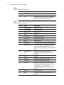
1
Vehicle Installation
Guide
Mobile
Workstation
MW 800
Series
ab
Models:
F5206, F5207 & F5217
6802967C20-E
@6802967C20@
COMPUTER SOFTWARE COPYRIGHTS
The Motorola products described in this instruction manual may include copyrighted Motorola computer programs stored in semiconductor memories or
other media. Laws in the United States and other countries preserve for Motorola certain exclusive rights for copyrighted computer programs, including
the exclusive right to copy or reproduce in any form the copyrighted computer program. Accordingly, any copyrighted Motorola computer programs contained In the Motorola products described in this instruction manual may not be copied or reproduced in any manner without the express written permission of Motorola. Furthermore, the purchase of Motorola products shall not be deemed to grant either directly or by implication, estoppel or otherwise,
any license under the copyrights, patents or patent applications of Motorola, except for the normal non-exclusive, royalty free license to use that arises
by operation of law in the sale of a product.
EPS – 34440- B
This warranty applies within the fifty (50) United States, the District of Columbia and Canada.
LIMITED WARRANTY
MOTOROLA COMMUNICATION PRODUCTS
If the affected product is being purchased pursuant to a written Communications System Agreement signed by Motorola, the warranty contained in that
written agreement will apply. Otherwise, the following warranty applies.
I. WHAT THIS WARRANTY COVERS AND FOR HOW LONG:
Motorola Inc. or, if applicable, Motorola Canada Limited ("Motorola") warrants the Motorola manufactured radio communications product, including
original equipment crystal devices and channel elements ("Product"), against material defects in material and workmanship under normal use and
service for a period of One (1) Year from the date of shipment.
Motorola, at its option, will at no charge either repair the Product (with new or reconditioned parts), replace it with the same or equivalent Product
(using new or reconditioned Product), or refund the purchase price of the Product during the warranty period provided purchaser notifies Motorola
according to the terms of this warranty. Repaired or replaced Product is warranted for the balance of the original applicable warranty period. All
replaced parts of the Product shall become the property of Motorola.
This express limited warranty is extended by Motorola to the original end user purchaser purchasing the Product for purposes of leasing or for commercial, industrial, or governmental use only, and is not assignable or transferable to any other party. This is the complete warranty for the Product
manufactured by Motorola. Motorola assumes no obligations or liability for additions or modifications to this warranty unless made in writing and
signed by an officer of Motorola. Unless made in a separate written agreement between Motorola and the original end user purchaser, Motorola does
not warrant the installation, maintenance or service of the Product.
Motorola cannot be responsible in any way for any ancillary equipment not furnished by Motorola which is attached to or used in connection with the
Product, or for operation of the Product with any ancillary equipment, and all such equipment is expressly excluded from this warranty. Because each
system which may use the Product is unique, Motorola disclaims liability for range, coverage, or operation of the system as a whole under this warranty.
II. GENERAL PROVISIONS:
This warranty sets forth the full extent of Motorola’s responsibilities regarding the Product. Repair, replacement or refund of the purchase price, at
Motorola’s option, is the exclusive remedy. THIS WARRANTY IS GIVEN IN LIEU OF ALL OTHER EXPRESS WARRANTIES. MOTOROLA DISCLAIMS ALL OTHER WARRANTIES OR CONDITIONS, EXPRESS OR IMPLIED, INCLUDING THE IMPLIED WARRANTIES OR CONDITIONS OF
MERCHANTABILITY AND FITNESS FOR A PARTICULAR PURPOSE. IN NO EVENT SHALL MOTOROLA BE LIABLE FOR DAMAGES IN
EXCESS OF THE PURCHASE PRICE OF THE PRODUCT, FOR ANY LOSS OF USE, LOSS OF TIME, INCONVENIENCE, COMMERCIAL LOSS,
LOST PROFITS OR SAVINGS OR OTHER INCIDENTAL, SPECIAL, INDIRECT OR CONSEQUENTIAL DAMAGES ARISING OUT OF THE USE
OR INABILITY TO USE SUCH PRODUCT, TO THE FULL EXTENT SUCH MAY BE DISCLAIMED BY LAW.
III. HOW TO GET WARRANTY SERVICE:
Purchaser must notify Motorola’s representative or call Motorola’s Customer Response Center at 1-800-247-2346 within the applicable warranty
period for information regarding warranty service.
IV. WHAT THIS WARRANTY DOES NOT COVER:
A)
B)
C)
D)
E)
Defects or damage resulting from use of the Product in other than its normal and customary manner.
Defects or damage from misuse, accident, water, or neglect.
Defects or damage from improper testing, operation, maintenance, installation, alteration, modification, or adjustment.
Breakage or damage to antennas unless caused directly by defects in material workmanship.
A Product subjected to unauthorized Product modifications, disassemblies or repairs (including, without limitation, the addition to the Product of nonMotorola supplied equipment) which adversely affect performance of the Product or interfere with Motorola’s normal warranty inspection and testing
of the Product to verify any warranty claim.
F) Product which has had the serial number removed or made illegible.
G) Batteries (they carry their own separate limited warranty).
H) Freight costs to the repair depot.
I) A Product which, due to illegal or unauthorized alteration of the software/firmware in the Product, does not function in accordance with Motorola’s
published specifications or with the FCC type acceptance labeling in effect for the Product at the time the Product was initially distributed from Motorola.
J) Scratches or other cosmetic damage to Product surfaces that do not affect the operation of the Product.
K) That the software in the Product will meet the purchaser’s requirements or that the operation of the software will be uninterrupted or error-free.
L) Normal and customary wear and tear.
M) Non-Motorola manufactured equipment unless bearing a Motorola Part Number in the form of an alpha numeric number (i.e., TDE6030B).
V. GOVERNING LAW
In the case of a Product sold in the United States and Canada, this Warranty is governed by the laws of the State of Illinois and the Province of
Ontario, respectively.
VI. PATENT AND SOFTWARE PROVISIONS:
Motorola will defend, at its own expense, any suit brought against the end user purchaser to the extent that it is based on a claim that the Product or
its parts infringe a United States patent, and Motorola will pay those costs and damages finally awarded against the end user purchaser in any such
suit which are attributable to any such claim, but such defense and payments are conditioned on the following:
A) that Motorola will be notified promptly in writing by such purchaser of any notice of such claim;
B) that Motorola will have sole control of the defense of such suit and all negotiations for its settlement or compromise; and
C) should the Product or its parts become, or in Motorola's opinion be likely to become, the subject of a claim of infringement of a United States patent,
that such purchaser will permit Motorola, at its option and expense, either to procure for such purchaser the right to continue using the Product or its
parts or to replace or modify the same so that it becomes non-infringing or to grant such purchaser a credit for the Product or its parts as depreciated
and accept its return. The depreciation will be an equal amount per year over the lifetime of the Product or its parts as established by Motorola.
Motorola will have no liability with respect to any claim of patent infringement which is based upon the combination of the Product or its parts furnished hereunder with software, apparatus or devices not furnished by Motorola, nor will Motorola have any liability for the use of ancillary equipment
or software not furnished by Motorola which is attached to or used in connection with the Product. The foregoing states the entire liability of Motorola
with respect to infringement of patents by the Product or any of its parts thereof.
Laws in the United States and other countries preserve for Motorola certain exclusive rights for copyrighted Motorola software such as the exclusive
rights to reproduce in copies and distribute copies of such Motorola software. Motorola software may be used only in the Product in which the software was originally embodied and such software in such Product may not be replaced, copied, distributed, modified in any way, or used to produce
any derivative thereof. No other use including, without limitation, alteration, modification, reproduction, distribution, or reverse engineering of such
Motorola software or exercise of rights in such Motorola software is permitted. No license is granted by implication, estoppel or otherwise under
Motorola patent rights or copyrights.
EPS – 48759 – O
FCC INTERFERENCE WARNING
The FCC requires that manuals pertaining to Class A and Class B computing devices must contain warnings about possible interference with local residential radio and TV reception. This warning reads as follows:
NOTE: This equipment has been tested and found to comply with limits for a Class B digital device, pursuant to Part 90 of the FCC Rules. These limits
are designed to provide reasonable protection against harmful interference when the equipment is operated in a commercial or residential environment.
This equipment generates, uses, and can radiate radio frequency energy and, if not installed and used in accordance with the instruction manual, may
cause harmful interference to radio communications.
For detailed product safety and RF exposure for mobile stations with two-way radios installed in vehicles, refer to Electromagnetic Emission (EME)
safety leaflet, Motorola publication Number 68P02967C16.
Trademarks
Trademarks
Motorola and the Stylized M logo are registered trademarks of Motorola Inc.
Private DataTAC is a registered trademark of Motorola Inc.
iDEN is a registered trademark of Motorola Inc.
Microsoft, Windows and the Windows logo are registered trademarks of Microsoft Corporation.
Pentium, Intel and FlashFile are registered trademarks of Intel Corporation.
GlidePoint is a registered trademark of Cirque Corporation.
The Bluetooth trademarks are owned by their proprietor and used by Motorola, Inc. under license in the U.S. and other countries.
IBM is a registered trademark of International Business Machines Corp.
Symbol is a registered trademark of Symbol Technologies Inc.
Trimble is a registered trademark of Trimble Navigation Limited
Mobile Mark is a registered trademark of Mobile Mark Inc.
All other product or service names are the property of their respective owners.
Internet Web Site Notice
The URL references in this manual are subject to change without notice.
Contents
References............................................................................................. 1
MW 800 Publications ............................................................................................ 1
Internet Web Sites.................................................................................................. 1
Using this Manual ................................................................................ 3
Who Should Use this Manual ................................................................................ 3
What is in this Manual ........................................................................................... 3
Safe Handling Instructions..................................................................................... 3
FCC Compliance Notice...........................................................................................
FCC Grant Of Equipment Authorization .................................................................
Notational Conventions ............................................................................................
Warning ....................................................................................................................
Caution .....................................................................................................................
Note ..........................................................................................................................
3
4
4
4
4
4
Introduction ......................................................................................... 5
Mount Features ...................................................................................................... 5
General Description ............................................................................................... 5
Installation............................................................................................ 7
Unpacking .............................................................................................................. 7
Preparing to Install the MW 800 Inside the Vehicle ............................................. 7
Tools ......................................................................................................................... 7
Planning.................................................................................................................... 7
MW 800 Mounting Location.................................................................................... 8
Equipment Ventilation.............................................................................................. 8
Air Bag Considerations ............................................................................................ 9
Environmental Considerations ............................................................................... 11
Electrical Guidelines .............................................................................................. 11
Mobile Antenna Installation ................................................................................... 11
Installation Procedure .......................................................................................... 12
Mounting the MW 800 ...........................................................................................
MW 800 Keyboard .................................................................................................
MW 800 Display ....................................................................................................
MW 800 CPU Box .................................................................................................
MW 800 GPS Antenna...........................................................................................
12
13
14
15
16
Government & Enterprise Mobility Solutions
1301 E. Algonquin Road, Schaumburg, IL 60196
Copyright © 2005 Motorola All Rights Reserved.
6802967C20-E
March, 2005
2
MW 800 Vehicle Installation Guide
Interconnection of the MW 800 CPU Box .......................................................... 17
................................................................................................................................
W-WAN Antenna Connection ...............................................................................
W-LAN Radio (802.11b) Connection ....................................................................
GPS Connection .....................................................................................................
Video In Connection...............................................................................................
Display Connections...............................................................................................
USB Connections ...................................................................................................
Firewire Connection ...............................................................................................
Serial Connection ...................................................................................................
LAN Connection ....................................................................................................
Microphone Connection .........................................................................................
Audio Out Connection............................................................................................
PWR Connection ....................................................................................................
AUX Connection ....................................................................................................
19
19
19
19
19
19
20
20
20
20
20
20
20
21
Ignition Sense Connection ................................................................................... 21
Turn-on Modes .................................................................................................... 22
Using the Power Button or Ignition Key to Start the MW 800 ..............................
Using the Power Button and Ignition Key to Start the MW 800............................
Using the Power Button to Start the MW 800........................................................
Using the Ignition Key to Start the MW 800 .........................................................
22
22
22
22
Turning On the MW 800 ..................................................................................... 23
Turning Off the MW 800..................................................................................... 23
Replacing Power Cable Fuse (Vehicle Power).................................................... 23
Storage ................................................................................................................. 24
Receptacles ......................................................................................... 25
Accessories.......................................................................................... 35
Acronyms............................................................................................ 39
Glossary .............................................................................................. 41
General Specifications ....................................................................... 43
References
You may need to refer to the documents listed below for further information. These
documents can be obtained from the following source:
Motorola Americas Parts Division
Motorola Literature Distribution Center
Motorola Centralized Customer Service
1313 E. Algonquin Road
Schaumburg, IL 60196
2290 Hammond Drive
Schaumburg, IL 60172
1-800-422-4210 FAX 1-847-538-8198
1-847-576-2828 FAX 1-800-576-5891
Please note that this manual provides general references to SDI (Scientific Dimensions, Inc.)
mounts and accessories. To obtain detailed information regarding SDI mounts, please refer to
SDI publications.
MW 800 Publications
Document
Equip. Model No.
Document No.
Mobile Workstation MW 800 Owner’s Manual
F5206
6802967C30
Mobile Workstation MW 800
Product Safety and RF Exposure for Mobile
Stations
F5206, F5207,
F5217
6802967C16
Mobile Workstation MW 800 Owner’s Manual
F5207, F5217
6802976C60
Mobile Workstation MW 800 User’s Guide
F5207, F5217
6802976C65
Mobile Workstation MW 800 Maintenance
Programming Software
F5207, F5217
6802976C70
Mobile Workstation MW 800 12.1” Display
Owner’s Manual
FLN3157,
FLN3167,
FLN3168,
FLN3169
6802976C75
Mobile Workstation MW 800 8.4” Display
Owner’s Manual
FLN3221
6802970C95
Mobile Workstation MW 800 8.4” Display
Vehicle Installation Guide
FLN3221
6802973C30
Internet Web Sites
Motorola Web site: http://www.motorola.com
SDI Web site: http://www.sdi.cc
Please note that the Web site location references in this manual are subject to change without
notice.
2
MW 800 Vehicle Installation Guide
This page Intentionally left blank
Using this Manual
Who Should Use this Manual
This manual is intended for trained service technicians, radio engineers, and technical
operation support staff who install the Mobile Workstation 800 (MW 800) (Models F5206,
F5207 and F5217) in a vehicle.
What is in this Manual
“Introduction”, lists the features of the MW 800 vehicle mount.
“Installation”, describes the tools and equipment, planning requirements, and product
inspections necessary for a smooth installation of the MW 800.
Safe Handling Instructions
FCC Compliance Notice
This equipment has been tested and found to comply with the limits for a Class B digital
device, pursuant to Part 90 of the FCC Rules. These limits are designed to provide reasonable
protection against harmful interference in a residential installation. This equipment
generates, uses, and can radiate radio frequency energy and, if not installed and used in
accordance with the instructions, may cause harmful interference to radio communications.
However, there is no guarantee that interference will not occur in a particular installation. If
this equipment does cause harmful interference to radio or television reception, which can be
determined by turning the equipment OFF and ON, the technician is encouraged to try to
correct the interference by one or more of the following measures:
• Reorient or relocate the receiving antenna.
• Increase the separation between the equipment and the receiver.
• Connect the equipment into an outlet on a different circuit from that to which the receiver
is connected.
• Consult the dealer or an experienced radio/TV technician for help.
For detailed product safety and RF exposure for mobile stations with two-way radios
installed in vehicles, refer to Electromagnetic Emission (EME) safety leaflet, Motorola
publication Number 68P02967C16.
4
MW 800 Vehicle Installation Guide
FCC Grant Of Equipment Authorization
Table 1
FCC Grant of Equipment Authorization
Radio
Network
FCC ID
Freq Band (MHz)
Power
DataTAC
Private DataTAC
PQS-BM28001
806-825
1.8W
g18
GPRS
IHDT6AC1
900/1900 or 925/1800
2W/1W
iO1000
iDEN
AZ489FT5796
806-821
0.6W
Wireless LAN
WLAN 2.4 GHz
H9PLA4137
2400
100 mW
2400
1 mW
(for model F5206)
PD9WM3B2200BG
(for model F5207)
Bluetooth
WPAN
AZ489FT7006
Notational Conventions
Throughout this publication, you will notice the use of warnings, cautions, and notes. These
notations are used to emphasize that safety hazards exist, and care must be taken.
Do not proceed beyond a WARNING or CAUTION until the indicated conditions are fully
understood and met.
Warning
.
!
Indicates a potentially hazardous situation which, if not avoided, COULD
result in death or serious injury.
!
Indicates a potentially hazardous situation which, if not avoided, MAY result in
minor or moderate injury. CAUTION may also be used to alert against unsafe
practices and property-damage-only accident hazards.
Warning
Caution
.
Caution
Note
.
An operational procedure, practice, condition, etc., which it is essential to
emphasize.
Note
.
Introduction
This section lists the features of the Mobile Workstation 800 (MW 800) vehicle mount.
Note
This section refers to a specific models of Motorola or SDI
manufactured mounts. Please note that the MW 800 may also be
installed with any other models of Motorola or SDI manufactured
mounts.
Mount Features
The MW 800 mount:
• Holds the MW 800 display within easy view of the driver
• Permits easy access to the dashboard controls
• Permits easy access to and removal of the keyboard
• Enables easy access or, if preferred, prevents access with flexible placement of the CPU
box
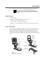
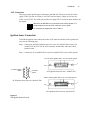
General Description
The MW 800 Mount assembly (DSSDI 8400) is comprised of five major components: the
base plate, pedestal, keyboard holder, display holder and an optional CPU box mount (see
Figure 1). All four assemblies are shipped as a complete unit with a hardware bag for
mounting to the customer’s vehicle hump. In case your vehicle does not have an hump,
elevate the mount assembly by installing a tunnel plate between the driver and the passenger
seats
Display
Holder
Keyboard
Holder
Display
Keyboard
CPU Box
Pedestal
Base Plate
Tunnel Plate
DSSDI MW800K1
Figure 1
MW 800 Mount Assembly Parts
CPU Box
Mount
DSSDI 8410
6
MW 800 Vehicle Installation Guide
The pedestal assembly is mounted on a base plate, terminating in a double clevis that accepts
the display assembly. The base plate is connected to the vehicle hump (or tunnel plate) by
eight bolts. The pedestal assembly has horizontal extension pedestal attached at the middle of
the vertical assembly to accommodate the simple attachment of the keyboard assembly and
CPU box mount.
The keyboard assembly allows for the quick insertion and removal of the MW 800 keyboard.
The keyboard platform swivels left and right freely, with adjustment friction setting. The
keyboard platform can also be tilted and locked in the required position by loosening a knob
on the underside of the platform. The keyboard is removed by pressing up on the spring
loaded flange, under the keyboard platform. The keyboard is installed by placing the back of
the keyboard against the locating flanges on the back vertical wall of the platform and
pressing down the front so that the spring flange engages the detente on the front of the
keyboard.
The CPU box mount allows the CPU box to be mounted on the pedestal and can protrude
forward or backward from the pedestal (see Figure 8 and Figure 9). The CPU box mount can
be installed in any other suitable location inside the vehicle.
Motorola recommends the use of the CPU mount. Failure to do so
may result in hard drive damage due to vibration.
Note
The display assembly is attached directly to the MW 800 display using the provided
hardware in the display kit (not SDI supplied). The display can be swiveled a total of 20
degrees, ±10 degrees in each direction. The display tilt limits are 10 degree backward
towards the dashboard and 45 degrees forward tilt. The swivel friction is adjustable by
tightening the 10-32 nylok nuts under the display perch. The handle at the top center of the
display (part of the display) is used to bring the display down. Grabbing the display on both
sides and twisting it slightly allows the rotation of swivel to occur.
Installation
This section describes the tools and equipment, planning requirements, and product
inspections necessary for a smooth installation of the Mobile Workstation 800 (MW 800).
Proper planning will help to ensure that the installation is completed without difficulty and
that no damage occurs to the units or the vehicle.
!
Caution
!
The MW 800 is a reliable product when installed correctly. However,
performance can be seriously impaired if it is not installed correctly.
Thoughtful planning can make the difference.
Please note that installing any part of the MW 800 must be according to
the instructions provided in this manual or by SDI.
Warning
Unpacking
Carefully unpack each item from the shipping carton. Check all items for shipping damage,
and make sure you have received all items ordered.
If there is damage or missing items, retain the shipping carton for inspection.
The following parts are used to mount the MW 800:
• Mount assembly
• CPU box mount kit for the MW 800 CPU V056AQ (optional)
• Mobile Workstation MW 800 Vehicle Installation Guide, 68P02967C20
Preparing to Install the MW 800 Inside the Vehicle
Tools
The following tools and service aids are required for installation:
• 3/8” nut driver
• 1/2”, 3/8” or 7/16” wrench
• No. 2 and 4 Phillips screwdriver
• Drill with 3/16” drill bit
Planning
Be sure to consider the following issues when planning the installation:
• Keyboard and display location relative to air bag deployment zones
• Environmental considerations
• Electrical guidelines
• Liquid Propane (LP) gas warning
8
MW 800 Vehicle Installation Guide
• Usability by driver/operator
• Vehicle vendor instructions
• Local vehicle authority regulations/design rules
When installing the MW 800, make sure that the CPU box mount or
any support is tightly anchored to the vehicle structure. Wobbly mount
can damage the hard drive.
!
Caution
MW 800 Mounting Location
The MW 800 is typically installed on a mount assembly, which affixes directly to the vehicle
transmission hump or to the Tunnel plate (preferred and not included in the kit).
Using an optional tall pedestal under the MW 800 is recommended only for use in vehicles
where air bag compliance is not required. An example of this is a utility van which does not
have passenger-side air bags for the given model year.
Correct positioning of the pedestal will ensure that the MW 800 meets the following
requirements:
• It is within easy reach of the driver/operator (more difficult due to air bag constraints)
• It will not injure the operator or passenger in case of an accident
• It does not interfere with the driver’s vision
• The workstation is properly ventilated
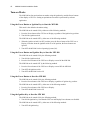
Equipment Ventilation
The display and CPU box are designed to operate properly in an ambient temperature range
of -22°F to 158°F (-30°C to +70°C). The MW 800 CPU must be installed in an area with
adequate air flow to allow for proper ventilation. Installers must install the CPU in an
unobstructed location in order to allow proper air flow (see Figure 2). It is imperative to
avoid installing the CPU in an enclosure or next to heat generating equipment such as: radio
transmitters, power amplifiers or a cabin heater.
Clear 1.6”
(40 mm)
Clear 0.4” (10 mm)
Air Outlet from Fans
Clear 1.6”
(40 mm)
Clear 0.4”
(10 mm)
Air Inlet to Fans
Clear 0.4” (10 mm)
Figure 2
Clear Ventilation Area Around the CPU Box
Installation
9
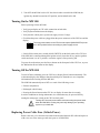
Air Bag Considerations
Provided for your reference are several air bag deployment zone templates from automobiles
used in public safety roles (Figure 3, Figure 4 and Figure 5). It is very important to obtain the
official documents of the automobile to ensure the safe installation.
Copyright © 2002 Ford Motor Company
Figure 3
Air Bag Deployment Zones - Crown Victoria
.
Figure 4
Air Bag Deployment Zones - Caprice
10
MW 800 Vehicle Installation Guide
.
Figure 5
Air Bag Deployment Zones - Lumina
Installation
11
Environmental Considerations
Consider the environmental parameters listed in the General Specifications section before
installing the MW 800.
.
!
For operation in hot climates, the vehicle must be adequately
ventilated (for temperatures see General Specifications section).
Caution
Electrical Guidelines
Be sure that the vehicle’s electrical system is in good condition. Faults in the alternator and
ignition system can be a source of severe Radio Frequency Interference (RFI) and can result
in MW 800 operating problems. Correct any problems in the alternator output, ignition
system, and battery condition before beginning the installation.
!
DO NOT install the workstation in a vehicle with a positive-ground
electrical system.
Caution
The power requirement for operating the MW 800 is 13.8VDC +/- 20%, 15A, negative
ground. The vehicle must have an alternator that can produce a high-current output at low
speed (below 18 m.p.h. or 29 km/h) and in an idle state. It also needs the highest rated heavyduty battery available for the vehicle. The power cables of the MW 800 should be directly
connected to the power system of the vehicle.
!
Caution
Avoid using power Battery Saver relays that cut-off power ruthlessly
between the MW 800 main power and the power system of the vehicle.
Uncontrolled power cut-off can damage the MW 800 operating system
and may require re-imaging of the hard drive. If a power cut-off device
is used in order to conserve vehicle battery life, please consult a
qualified Motorola authorized installation shop or contact the Motorola
system support center for assistance..
Cables longer than 10 ft. (3.05 m) should be routed through special UL listed conduit/duct
for electrical cables. This conduit/duct should fully enclose the cable along its whole length.
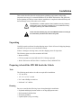
Mobile Antenna Installation
Vehicle antennas must be installed external to the vehicle and in accordance with:
• The requirements of the antenna manufacturer/supplier.
• Instructions in the installation manual of the external radio (in case an external radio is
used).
12
MW 800 Vehicle Installation Guide
Installation Procedure
Mounting the MW 800
Perform the following steps to install the MW 800:
Step 1. Determine the proper mounting location.
Step 2. Remove the hardware bag from the shipping container.
Step 3. Ensure that the pedestal is securely bolted together.
Step 4. The mount assembly can be mounted directly on the vehicle transmission hump
secured rigidly to the vehicle transmission hump. (Commercial hump plates are
available, such as the SDI 7200 system or equivalent).
Figure 6
Figure 7
Mount Assembly General View (CPU Box Mount at rear)
Mount Assembly General View (CPU Box Mount at front)
Figure 8
Figure 9
MW 800 on Mount Assembly (CPU Box at rear)
MW 800 on Mount Assembly (CPU Box at front)
Installation
13
Step 5. Place the mount assembly with the CPU Box mount (if desired) in the vehicle and
use it for marking the location of the base plate or the hump plate on the vehicle
transmission hump. If no hump exists, place the pedestal or SDI tunnel plate between
the driver and the passenger seats for marking the location.
Step 6. At the proper location, drill four 1/4” holes into the transmission hump or the hump
plate in order to achieve optimal functionality and use of the MW 800.
.
!
Caution
Be careful not to drill into the transmission. Some commercially
available hump plates, such as the SDI 7200 system, may
have the hole pattern already pre-drilled.
Step 7. Attach the pedestal to the desired anchor point on the transmission hump or on the
hump plate, using studs and nuts, screws and nuts or self-tapping screws, as required.
Steps 8 and 9 are optional for adjusting the tilt tension.
Step 8. Remove the two end caps.
Step 9. Fold down tension should be adjusted by tightening the two 5/16” nuts at the edges
of the folding mechanism. This can also be done when the MW 800 display is
installed on the mount assembly.
Step 10. Attach the display to the mount and route the Display Signal Cable down the
pedestal. Ensure that the Display Signal Cable has enough slack to move when the
display is tilted down.
Step 11. Rotate the keyboard left and right to determine the range of swivel. Some hump
plates are attached to the anchor points of the seats. These hump plates allow
adjustment front to back, thus allowing for fine-tuning of the installation.
Step 12. Fold the display up and down to determine the available range for the given vehicle
and application. When mounting the keyboard, care must be exercised to ensure
sufficient space for proper installation of the device. This will restrict the amount of
tilt/swivel available.
MW 800 Keyboard
The keyboard tray is attached to the MW 800 mount. The keyboard tray may be removed if
desired and can be tilted or swiveled.
If required, the keyboard can be placed elsewhere in the vehicle to allow for use of other
installed equipment. Please ensure that all safety guidelines and air-bag deployment
requirements are met.
The keyboard is provided with a quick release holder to allow operation of the keyboard
when out of the holder. Care must be used to ensure ample space for extracting and
reinserting the keyboard into the holder. Ensure that the cable is routed in a manner that
allows the operator to remove the keyboard from the mounting tray and operate the keyboard
in their lap.
14
MW 800 Vehicle Installation Guide
MW 800 Display
The MW 800 display is attached to the display mount by Phillips screws (M4), supplied in
the display shipping carton. The Display Signal Cable is routed from the CPU box, through
the mount, and connected to the lower back side of the display. Use caution when assembling
the cable to the display, to prevent damage to the display or the cable. Form a service loop for
the Power and Display Signal Cables to reduce cable tension. Use plastic cable ties to secure
the cables to cable tie points.
Allow Service
Loop
Power Cable
USB Keyboard Cable
Display Signal Cable
Figure 10
Display Cable Route
!
Caution
Long Display Signal Cables (longer than 3 Meter, 9.14 foot) should be routed
inside protective ducts to avoid damage
Installation
15
MW 800 CPU Box
The MW 800 CPU box should be mounted so that the cables from the keyboard(s),
display(s), power system and peripherals can be attached. The limiting factor is the 17 feet
length of the display signal cable. When attached to the display, this cable is routed down
through the pedestal to the CPU box. Use plastic cable ties to secure the cables to the cable
tie bracket.
Cable Tie Bracket
Figure 11
CPU Box - Cable Tie Bracket (F5206 only)
Radio modems can be installed inside the CPU box via the PC card slot. The antenna cable
can be routed to an external antenna through one of the two openings located on the back side
of the PC card door (see Figure 12).
Do not remove the seals from the PC card door. The seals press
against the antenna cable when the door is closed.
Note
Radio Modem
Openings in PC Card Door
Seal
Seal
Antenna Cable
Figure 12
CPU Box - Antenna Cable Route of Radio Modem Installed in PC Card Slot
16
MW 800 Vehicle Installation Guide
The CPU box can be mounted anywhere in the passenger compartment of the vehicle that
provides adequate ventilation (see Figure 2).
It is recommended that the CPU box be mounted in a place where the PC Card slot can be
easily accessed.
In addition, attach the adhesive tapes provided in the shipping carton to the PC Card to
facilitate easy removal.
Suggested locations, in order of preference, are: on the CPU box mount, on the prisoner cage,
under the dashboard, in the console, or under the seat (not in the direct path of the vehicle
heater air flow). If the CPU box is mounted on the base plate of the mount assembly, it must
be mounted using the CPU box mount.
The CPU box mount can be affixed to the base plate in two possible orientations (see Figure
8 and Figure 9):
1. On the base plate, directly under the keyboard tray (see Figure 9).
2. On the base plate, using different mounting holes in the opposite direction to the
keyboard tray (see Figure 8).
MW 800 GPS Antenna
To install the GPS antenna, perform the following steps:
Step 1. Drill a hole into the mounting surface for the antenna post.
Step 2. Release the nut and the flat washer from the antenna post and insert the post into the
hole.
Step 3. Secure the post with the flat washer and the nut.
Installation
17
Interconnection of the MW 800 CPU Box
This section refers to MW 800 with display, keyboard and peripherals. Figure 13 and Figure
14 show an optional connection layout for the MW 800, and Figure 16 shows the display
connections. Note that any USB 1.1(model F5206) or USB 2 (model F5207), RS-232,
Firewire or Bluetooth based devices may be used.
With the mechanical installation complete, hook up the optional antennas and other required
options to the CPU box and display.
Ensure that the cables are properly routed to prevent damage to the cables and any operator
hazards. Connect the DC Power cables at the end of the connection procedure.
Camera
Vehicle Power
System
GPS Antenna
15 A Fuse
DC Power
Cable
15 A Fuse
15 A
Fuse
Wireless LAN
Antenna
GPRS
Antenna
Bluetooth
Display
Signal Cable
Ignition Sense
Input
Display 1
USB 1
Digital
I/O
Power
Cable
USB 2
12VDC & 5VDC
(2 Amps Max)
Power Output
Display RGB
Signal Cable
Headset
Bluetooth
Display 2
USB 1
LAN Network
USB 2
Mic
Data Storage Device
External Radio
Figure 13
MW 800 - Optional Connection Layout for Model F5206
Power Cable
18
MW 800 Vehicle Installation Guide
Vehicle Power System
15 A Fuse
GPS Antenna
15 A Fuse
Wireless LAN
Antenna
15 A
Fuse
Bluetooth
GPRS
Antenna
Camera
DC Power
Cable
Ignition Sense
Input
Display
Signal Cable
MAIN SWITCH
W-
LAN
MIC
SERIAL
AUX
Digital
I/O
Display 1
PWR
GPS
IN
W-WAN
13.8V
AUDIO OUT
VIDEO IN
DISPLAY 1
USB 1
Power
Cable
USB
LAN
USB
DISPLAY 2
12VDC & 5VDC
(2 Amps Max)
Power Output
End
F1
Caps
Lock
USB 2
F2
~
Tab
FIREWIRE
F3
!
1
Q
@
2
E
S
Z
Ctrl
F4
F5
#
3
W
A
$
4
R
D
X
F
C
F6
%
5
6
T
Y
G
V
F7
F8
&
7
B
7
U
H
N
F9
8
1
M
(
9
8
I
4
J
0
P
<
,
>
.
Ins
Alt
.
+
=
?
/
Del
}
]
"
'
+
|
\
Shift
/
Fn
B
Display RGB or DVI
Signal Cable
Bluetooth
Display 2
USB 1
LAN Network
Headset
USB 2
Power Cable
End
F1
F2
~
Tab
Caps
Lock
F3
@
2
!
1
Q
W
A
#
3
E
S
Z
Ctrl
F4
F5
$
4
R
D
X
F6
%
5
T
F
C
F7
Y
G
V
F8
&
7
6
U
H
B
F9
1
M
(
9
8
I
4
J
N
8
7
<
,
B
Data Storage Device
External Radio
Figure 14
MW 800 - Optional Connection Layout for Model F5207
Figure 15
MW 800 - Optional Connection Layout for Model F5217
>
.
.
F12
Num
Lock
+
=
Back Spa ce
{
[
-
:
;
3
Ins
A
_
P
6
L
2
Alt
F11
)
0
O
5
K
0
F10
9
?
/
}
]
"
'
+
Del
Prt Scr
|
\
Pa use
PgUp
Enter
Shift
/
Fn
Esc
Pau se
PgUp
Enter
A
Mic
Prt Scr
Back Space
{
[
-
:
;
3
N um
Lock
F12
_
)
0
6
L
2
F11
F10
9
O
5
K
Esc
Installation
19
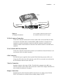
Display
To USB Peripheral Device
USB 1
To Vehicle Power
System
DC Cable
15 A Fuse
DC Power
Figure 16
12” Display Connections
Display Signal USB 2
Cable
To Keyboard
For 8.4" display connections, please refer to
the installation manual of the 8.4” display
W-WAN Antenna Connection
Connect the vehicle RF antenna cable connector (Mini UHF) if an internal Wireless Wide
Area Network (W-WAN) radio is installed (iDEN, GPRS, DataTAC). If the RF Power
Amplifier is used, this connection is made to the RF-IN connection on the RF Power
Amplifier, and the vehicle antenna is connected to the antenna connector on the RF Power
Amplifier.
W-LAN Radio (802.11b) Connection
Connect the vehicle RF antenna cable connector (reversed SMA) if internal Wireless Local
Area Network (W-LAN) radio is installed.
GPS Connection
The MW 800 may be supplied with an optional Global Positioning System (GPS) card.
Connect the GPS cable to the GPS connector on the CPU box rear panel on one side and to
the GPS antenna connector on the other side.
Video In Connection
Standard Composite video input (CVBS). The MW 800 is equipped with a BNC type
connector to which a video camera can be connected. A BNC to RCA adapter 5802810C07 is
also available from Motorola, if required.
Display Connections
Standard Interfaces Red Green Blue (RGB) connection for two display units (F5206 &
F5207). DVI interface is available for the secondary display of F5207.
20
MW 800 Vehicle Installation Guide
USB Connections
The MW 800 has use standard Universal Serial Bus (USB) type A receptacle connectors to
which any standard USB 1.1 (model F5206) or USB 2 (model F5207) device can be
connected. The CPU box USB connection is used for general purpose, and the display USB
receptacles are for QWERTY style keyboard and any general purpose device.
Firewire Connection
The MW 800 is equipped with one standard Firewire (IEEE1394) receptacle, to which any
standard Firewire device can be connected.
Serial Connection
The RS-232 port is an IBM® PC standard DB-9 male connector. This port can be used to
attach a radio modem, or any other serial device.
LAN Connection
Ethernet 10/100 Mb/s wire connection to Local Area Network (LAN) support.
Microphone Connection
The MW 800 is equipped with an Audio In connector to which an external microphone can
be connected.
Audio Out Connection
The MW 800 is equipped with an Audio Out connector to which external mono earphones
can be connected or external speaker with built-in amplifier. Adjustable volume buttons are
located on the display.
PWR Connection
The MW 800 is equipped with two Motorola DC power cables and fuses, one for the CPU
box and the second for the display. To connect power to the MW 800 units perform the
following steps:
Step 1. Route the power cable from the power connector on the MW 800 CPU box or display
to the vehicle power system using accepted industry methods and standards.
Step 2. Plug the cable tightly into the DC power connectors.
Step 3. Be sure to grommet the vehicle fire wall to protect the cable.
Connect the red wire to the positive (+) terminal of the battery, and the black wire to
the negative (-) terminal.
!
Caution
The black wire should be connected directly to the battery and
not to the chassis of the vehicle.
Installation
21
AUX Connection
This port provides ignition sense connection to the MW 800. This port can also be used to
supply 5VDC (2A max for F5206 1A for F5207) and car battery voltage out (2A max for
F5206 1A for F5207). The AUX port provides two digital TTL level one bit inputs and two one
bit outputs.
Whenever the MW 800 is not connected to the vehicle ignition, it is
recommended to leave the AUX connector cover in place.
Note
For complete pin assignment refer to Table 3.
Ignition Sense Connection
To install the ignition-sense cable between the AUX connector and the vehicle ignition line,
carry out the following steps:
Step 1. Connect one end of the ignition-sense wire to pin 1 (in model F5206) or pin 8 (in
models F5207 & F5217) of the AUX connector, and the other end to the vehicle
ignition switch.
Step 2. Connect pin 12 (in model F5206) or pin 4 (in model F5207) to the vehicle ground.
.
Pin 8 to vehicle ignition switch Pin 4 to vehicle ground
1
26
To vehicle ignition
switch
12
To vehicle
ground
AUX Ignition-Sense Pin-outs - Model F5207
Pin 8 to vehicle ignition switch Pin 5 to vehicle ground
AUX Ignition-Sense Pin-outs - Model F5206
1
26
AUX Ignition-Sense Pin-outs - Model F5217
Figure 17
AUX Ignition-Sense Pin-outs
22
MW 800 Vehicle Installation Guide
Turn-on Modes
The MW 800 has four optional turn-on modes using the ignition key and the Power buttons
of the display or CPU box. Setting an optional turn-on mode is performed by software
application.
Using the Power Button or Ignition Key to Start the MW 800
This mode is the default workstation setting.
The MW 800 can be turned ON by either one of the following methods:
1. Press the Power button of the CPU box or Display, regardless of the ignition key position.
2. Turn ON the ignition switch.
The MW 800 can be turned OFF by either one of the following methods:
1. When the ignition switch is in OFF position, press the Power button of the CPU box or
Display. Note that when the ignition switch is in ON position, the Power buttons are
ignored.
2. Turn OFF the MW 800 via the Operating System (OS).
Using the Power Button and Ignition Key to Start the MW 800
The MW 800 can be turned ON by the following method:
1. Turn ON the ignition switch.
2. Press the Power button of the CPU box or Display to turn ON the MW 800.
The MW 800 can be turned OFF by the following method:
1. Press the Power button of the CPU box or Display to turn OFF the MW 800.
2. Turn OFF the ignition switch.
3. Turn OFF the MW 800 via the OS.
Using the Power Button to Start the MW 800
The MW 800 can be turned ON by the following method:
1. Press the Power button of the CPU box or Display, regardless of ignition key position.
The MW 800 can be turned OFF by either one of the following method:
1. Press the Power button of the CPU box or Display.
2. Turn OFF the MW 800 via the OS.
Using the Ignition Key to Start the MW 800
The MW 800 can be turned ON by the following method:
1. Turn ON the ignition key. Note that the CPU box and Display Power buttons are disabled.
The MW 800 can be turned OFF by either one of the following methods:
1. Turn OFF the ignition key.
2. Turn OFF the MW 800 via the OS. Note that in order to turn ON the MW 800, the
ignition key should be turned to OFF position, and switched back to ON.
Turning On the MW 800
Before powering ON the MW 800:
• Verify proper display to CPU cable connection on both sides.
• Verify keyboard connection to the display.
• Verify that the vehicle power system can supply at least 15 Amps.
• Check that the power cables are plugged into the power connectors of the CPU box and the
display.
The main power switch on the CPU box back panel (MAIN SWITCH) must
be in OFF position before connecting to power supply source.
Note
• Switch ON the main power switch (MAIN SWITCH) on the back panel of the CPU box.
If the MW 800 is connected through the ignition switch, insert the car key into the ignition
switch and rotate it to ACC position, or start the engine, before powering ON.
To power the workstation, press the Power button on the front panel of the CPU box, or press
the Workstation Power button on the display.
Turning Off the MW 800
To turn Off the workstation, press the CPU box or display Power button momentarily. The
workstation displays the Windows shut-down dialog box. Remember to save important
information before turning OFF the MW 800.
The MW 800 automatically turns OFF as a result of the following events:
• Extreme temperatures
• Discharged vehicle battery
• Pressing the Power button on the CPU box or display for more than six seconds
In critical conditions or during maintenance, the workstation may be powered OFF by
turning the main power switch on the CPU box back panel.
!
Caution
Turning OFF the main power switch or disconnecting the power cable
when the MW 800 is running may seriously damage your operating
system or your hard disk.
Replacing Power Cable Fuse (Vehicle Power)
Remove the fuse (15A) from the fuse holder located on the Motorola DC cable and replace it
with a new one of the same type and value (part no. 6580283E06).
24
MW 800 Vehicle Installation Guide
Storage
Important Note: Maximum storage period in shipping package is six months. To refresh
storage, assemble the workstation and run Disk Defragmenter (Go to: Start->Programs>Accessories->System Tools->Disk Defragmenter)
Receptacles
25
Receptacles
Table 2
SERIAL Connection
Pin No.
Signal
1
DC0
2
RX1
3
TX1
4
DTR1
5
2_GND
6
DSR1
7
STS1
8
CTS1
9
RI1
Table 3
AUX Connection - Model F5206
Pin No.
Signal
Description
1
IGNITION_MODE
12V DC Ignition sense input from ignition key
2
INPUT1
Digital input TTL (5V) level
3
INPUT2
Digital input TTL level
4
OUTPUT1
Digital output TTL level
5
OUTPUT2
Digital output TTL level
6
DSC_EN
Aux Radio Enable input signal
7
DSC-UPLINK
Radio Output
8
DSC-DOWNLINK
Radio Input
9
+12V
Output power. Maximum 1 Amps. Output
inhibits when CPU box temperature is above
operating range
10
+12V
Output power. Maximum 1 Amps. Output
inhibits when CPU box temperature is above
operating range
11
N.C
-
12
GND
Ground
13
GND
Ground
26
MW 800 Vehicle Installation Guide
Table 3
AUX Connection - Model F5206
Pin No.
Signal
Description
14
MONITOR_MODE
Service input signal
15
+5V
Output power. Maximum 2 Amps. Output is
automatically disconnected when CPU box
temperature is above operating range
Table 4
AUX Connection - Model F5207
Pin No.
Signal
Description
1
USB-AUXPOS
USB I/O Positive
2
USB-AUXNEG
USB I/O Negative
3
VBUS-AUX
USB Output
4
GND
Ground
5
LINE-OUT-R
Right Speaker Output
6
LINE-OUT-L
Left Speaker Output
7
SPDIF
Digital Audio I/O
8
IGNITION
12V DC Ignition sense input from ignition key
9
BOOTBLOCK#
Crisis BIOS boot-up input signal (active low
signal). Used to boot the CPU box from an
external drive that connects to any of the USB
ports.
10
PROG-ENTERAUX
Enable input signal for the “one wire”
programming of the HC08 controller in the
CPU box
11
GND
Ground
12
MICNEG
Microphone negative output signal
13
VREF-MIC
Microphone positive output signal
14
V12-OUT
Output power. Maximum 1 Amps. Output
inhibits when CPU box temperature is above
operating range. The output power
corresponds to the power that operates the
CPU box
15
V12-OUT
Identical to pin 14
16
GPI0
General purpose digital input number 0, TTL
level (5V)
Receptacles
27
Pin No.
Signal
Description
17
GPI1
General purpose digital input number 1, TTL
level (5V)
18
GPO0
General purpose digital output number 0, TTL
level
19
GPO1
General purpose digital output number 1, TTL
level
20
1W
I/O data for “one wire” programming of the
HC08 controller in the CPU box
21
DSC-EN
Aux Radio Enable input signal for GPRS radio
programming
22
DSC-UPLINK
Radio Output
23
DSC-DOWNLINK
Radio Input
24
GND
Ground
25
V5-OUT
Power output. Maximum 1 Amps. Output is
automatically disconnected when CPU box
temperature is exceeds operating range
26
V5-OUT
Power output. Maximum 1 Amps. Output is
automatically disconnected when CPU box
temperature is exceeds operating range
Table 5
AUX Connection - Model F5217
Pin No.
Signal
Description
1
SPEED+
Positive vehicle
2
SPEED-
Negative vehicle
3
FWD+
Forward/Backward drive direction input signals
4
FWD-
Forward/Backward drive direction input signals
5
GND
Ground
6
GND
Ground
7
GND
Ground
8
IGNITION
12V DC Ignition sense input from ignition key
9
BOOTBLOCK#
Crisis BIOS boot-up input signal (active low signal).
Used to boot the CPU box from an external drive that
connects to any of the USB ports.
10
PROG-ENTERAUX
Enable input signal for the “one wire” programming of
the HC08 controller in the CPU box
speed input signals
speed input signals
28
MW 800 Vehicle Installation Guide
Pin No.
Signal
Description
11
GND
Ground
12
GND
Ground
13
GND
Ground
14
V12-OUT
Output power. Maximum 1 Amps. Output inhibits
when CPU box temperature is above operating
range. The output power corresponds to the power
that operates the CPU box
15
V12-OUT
Identical to pin 14
16
GPI0
General purpose digital input number 0, TTL level
(5V)
17
GPI1
General purpose digital input number 1, TTL level
(5V)
18
GPO0
General purpose digital output number 0, TTL level
19
GPO1
General purpose digital output number 1, TTL level
20
1W
I/O data for “one wire” programming of the HC08
controller in the CPU box
21
DSC-EN
Aux Radio Enable input signal for GPRS radio
programming
22
DSC-UPLINK
Radio Output
23
DSCDOWNLINK
Radio Input
24
GND
Ground
25
V5-OUT
Power output. Maximum 1 Amps. Output is
automatically disconnected when CPU box
temperature is exceeds operating range
26
V5-OUT
Power output. Maximum 1 Amps. Output is
automatically disconnected when CPU box
temperature is exceeds operating range
Table 6
USB Connection
Pin No.
Signal
1
VBUS0
2
USB0-
3
USB0+
4
3_GND
Table 7
IEEE 1394a (Firewire)
Pin No.
Signal
1
VFW
2
GND
3
TPB0-
4
TPB0+
5
TPA0-
6
TPA0+
Pin No.
Signal
1
TX_ENG
2
CTS1
3
TX_POS
4
RX_ENG
5
CT2
6
RX_PDS
Pin No.
Signal
1
Red
2
Green
3
Blue
4
VSYNC
5
USB(+)
6
USB(-)
7
SP4-L1
8
SP4-R1
9
MIC_POS
Table 8
LAN Connection
Table 9
DISPLAY 1 Connection
30
MW 800 Vehicle Installation Guide
Table 9
DISPLAY 1 Connection
Pin No.
Signal
10
USB-5V
11
POWERON1
12
USB-5V
13
SPARE
14
DDC_DATA
15
DDC_CLK
16
N.C
17
N.C
18
GND
19
GND
20
GND
21
GND
22
HSYNC
23
GND
24
N.C
25
SP4-L2
26
SP4-R2
27
MIC_NEG
28
GND
29
PRIMARY_MDR
30
GND
31
1_WIRE
32
N.C
33
N.C
34
N.C
35
N.C
36
GND
Table 10
DISPLAY 2 Connection - Model F5206
Pin No.
Signal
1
R_5
2
G_5
3
B_5
4
VSYNC_5
5
USB(+)_5
6
USB(-)_5
7
SP4-L1_5
8
SP4-R1_5
9
MIC1_5
10
USB-5V_5
11
POWERON1_5
12
USB-5V_5
13
GND
14
DDC1_5
15
DDC2_5
16
N.C
17
N.C
18
GND
19
GND
20
GND
21
GND
22
HSYNC_5
23
GND
24
N.C
25
SP4-L2_5
26
SP4-R2_5
27
MIC2_5
28
GND
29
POWERON2_5
30
GND
32
MW 800 Vehicle Installation Guide
Table 10
DISPLAY 2 Connection - Model F5206
Pin No.
Signal
31
DD_5
32
N.C
33
N.C
34
N.C
35
N.C
36
GND
Pin No.
Signal
1
TDC2
2
TDC2#
3
GND
4
TDC1#
5
TDC
6
GND
7
TDC0
8
TDC0#
9
GND
10
HSYNC
11
GND
12
VSYNC
13
GND
14
SPCLK
15
GND
16
SPDATA
17
GND
18
SECOND MDR
19
GND
Table 11
DISPLAY 2 Connection - Model F5207
Table 11
DISPLAY 2 Connection - Model F5207
20
SPARE1
21
GND
22
1W
23
GND
24
ON-OFF
25
GND
26
TLC
27
TLC#
28
GND
29
USB_NEG
30
USB_POS
31
GND
32
VBUS
33
GND
34
GND
35
RED
36
GND
37
BLUE
38
GND
39
GREEN
40
GND
41
HPDET
42
SECOND SPARE
43
GND
44
MICNEG
45
MICPOS
46
GND
47
HP-L
48
HP-L#
34
MW 800 Vehicle Installation Guide
Table 11
DISPLAY 2 Connection - Model F5207
49
HP-R
50
HP-R#
Speakers Out
4
3
2
Line Out Right
1
5
Line Out Left
Microphone In
4
3
2
IN and VREF
1
NC
5
Accessories
35
Accessories
Displays
Description
Nomenclature
COLOR DISPLAY 12.1" SVGA 300NIT HB. TOUCH SCREEN
FLN3157
COLOR DISPLAY 12.1" XGA 1200NIT HB. TOUCH SCREEN
FLN3167
COLOR DISP. 12.1" SVGA 300NIT With Bluetooth
FLN3168
COLOR DISP. 12.1" XGA 1200NIT With Bluetooth
FLN3169
DO NOT order secondary display with Bluetooth if primary display has
Bluetooth. ONLY one (1) display should have Bluetooth functionality.
COLOR DISPLAY 8.4" SVGA 350NIT, TOUCH SCREEN
FLN3221
Cables for 12.1" (for Primary Display)
Description
Nomenclature
4.5FT(1.5M) DISPLAY-CPU CABLE MW800
FKN8068
9.6FT (3M) DISPLAY-CPU CABLE, MW800
FKN8069
17FT (5.0M) DISPLAY-CPU CABLE, MW800
FKN8070
LINE OUT CABLE ADAPTOR, MW800 (F5206)
FKN8081
1.6FT(0.5M) LAP-TOP TO MW800 DISPLAY CABLE
FKN8090
1.6FT(0.5M) DISPLAY-CPU CABLE, MW800
FKN8131
12FT (3.6M) DISPLAY-CPU CABLE MW800
FKN8143
EXT. SPEAKER CABLE ADAPTOR (F5207 & F5217)
FKN8340
KEYBOARD EXTENDER CABLE, USB 6FT
FKN8201
MODS ADAPTER CABLE
FKN8215
Cables for 8.4" Display (for Primary Display)
Description
Nomenclature
12FT (3.5M) CPU TO 8.4' DISPLAY
FKN8216
16FT (5.0M) CPU TO 8.4' DISPLAY
FKN8217
Cables for Secondary Display
Description
Nomenclature
4.5FT(1.5M) CPU 2ND TO 8.4" DISPLAY (F5207)
FKN8336
9.6FT(3.0M) CPU 2ND TO 8.4" DISPLAY (F5207)
FKN8304
36
MW 800 Vehicle Installation Guide
16FT(5.0M) CPU 2ND TO 8.4" DISPLAY (F5207)
FKN8305
4.5FT(1.5M) CPU 2ND TO 12.1" DISPLAY (F5207)
FKN8306
9.6FT(3.0M) CPU 2ND TO 12.1" DISPLAY (F5207)
FKN8337
16FT(5.0M) CPU 2ND TO 12.1" DISPLAY (F5207)
FKN8307
Drives
Description
Nomenclature
USB FLOPPY DISK DRIVE
DDN6871
HARDWARE H.D 40GB
FHN6480
ML850 RM8 KIT DVD COMBO DRIVE
DDN7541
Keyboard
Description
Nomenclature
KEYBOARD,USB, BACKLIT,US, MW800
FLN9890
Microphones
Description
Nomenclature
MICROPHONE EXTERNAL MW 800 (F5207, F5217)
FLN3482
MICROPHONE EXTERNAL MW 800 (F5206)
FLN2957
Mounting Kits
Description
Nomenclature
MOUNTING TRUNNION
FHN6388
MOUNT, IN DASH SINGLE DIN, 8.4" DISPLAY
FLN3303
BALL JOINT CRADLE W/BASE & VESA PLATE, 8.4" DISPLAY
FLN3304
Speaker
Description
Nomenclature
SPEAKER KIT MOBILE (F5207, F5217)
FLN3481
EXT. SPEAKER CABLE ADAPTOR (F5207, F5217)
FKN8340
EXT. SPEAKER CABLE ADAPTOR (F5206)
FKN8186
SPEAKER KIT MOBILE (F5206)
FHN1669
Converter
Description
Nomenclature
Accessories
CONVERTER, USB TO 4 RS232
FLN2955
Others
Description
Nomenclature
9.6FT(3.0M) AUX cable 26/open (F5207, F5217)
FKN8338
9.6FT(3.0M) CPU DVI-D cable (F5207)
FKN8339
37
38
MW 800 Vehicle Installation Guide
This page Intentionally left blank
Acronyms
39
Acronyms
A
Ampere
ACK
Positive (Acknowledgment)
AUX
Auxiliary
CPU
Central Processing Unit
DC
Direct Current
DDRAM
Double Data Rate-Synchronous DRAM, a type of SDRAM
DRAM
Dynamic Random Access Memory
DTE
Data Terminal Equipment
DVI
Digital Video Interface
FCC
Federal Communications Commission
GHz
Gigahertz
GPI
General Purpose Input
GPO
General Purpose Output
GPRS
General Packet Radio Service
GPS
Global Positioning System
GSM
Global System for Mobile communication
I/O
Input/Output
iDEN
Integrated Digital Enhanced Network
IEEE
Institute of Electrical and Electronic Engineers
LAN
Local Area Network
LCD
Liquid Crystal Display
LP
Liquid Propane
MB
Megabyte
MDT
Mobile Data Terminal
MW
Mobile Workstation
NFPA
National Fire Protection Association
NIT
Near Infrared Transmission (also cd/m2, a measure of luminance)
NTSC
National Television System Committee
OS
Operating System
40
MW 800 Vehicle Installation Guide
PA
Power Amplifier
PAL
Phase Alternation Line
PC
Personal Computer
PC
Personal Card
PCI
Peripheral Component Interconnect
PRM
Portable Radio Modem
PWR
Power
RF
Radio Frequency
RFI
Radio Frequency Interference
SIM
Subscriber Identity Module
SVGA
Super Video Graphics Array
TFT
Thin Film Transistor
TTL
Transistor-Transistor Logic
UHF
Ultra High Frequency
UL
Underwriter’s Laboratories
USB
Universal Serial Bus
V
Volt
VDC
Volts Direct Current
VRM
Vehicular Radio Modem
WLAN
Wireless Local Area Network
WWAN
Wireless Wide Area Network
XGA
eXtended Video Graphics Array
Glossary
41
Glossary
C
Central Processing Unit (CPU): The computer in charge of fetching, processing, and
storing data, generally used to refer to the entire microprocessor chip.
D
Data Terminal Equipment (DTE): User terminal equipment which creates information
for transmission, for example, a user’s PC.
DB-25: A 25-pin connector used for V.24 or RS-232C interfaces.
DB-9: A standard 9-pin connector used for serial interfaces.
Direct Current (DC): Current that flows through a circuit in only one direction.
G
Global Positioning System (GPS): A constellation of 24 radio navigation (not
communication) satellites in six different orbits, which transmit signals used by GPS
receivers to determine precise location (position, velocity, and time) solutions.
M
Mobile Data Terminal (MDT): Vehicle installed device providing a data entry and display
user interface for data communication functions.
P
Personal Computer (PC): The generic term for a single user, microprocessor based
computer whose architecture is derived from the original IBM® Personal Computer.
R
Radio Frequency (RF): Refers to the electromagnetic energy wavelengths between the
audio and the light range (usually somewhere between 10 kHz and 300 GHz).
42
MW 800 Vehicle Installation Guide
Radio Frequency Interference (RFI): 1) The Radio Frequency (RF) radiation which
leaks from a device when it is transmitting. 2) Electrical disruption (noise) created by certain
types of equipment that may be radiated through air.
RS-232: The most common, standard interface used to connect Data Terminal Equipment
(DTE) to modems. It uses a DB-25 connector, although the DB-9 version has become
popular on PCs which have limited space for connectors.
U
Ultra High Frequency (UHF): Radio frequency, extending from 300 MHz to 600 MHz.
Underwriter’s Laboratories (UL): An independent and non-profit USA testing/
certification agency that was created by insurance companies to inspect electrical devices to
ensure there are no shock or fire hazards present.
Universal Serial Bus (USB): industry standard for PC bus interface enabling multi-drop
connection of both high-speed (12 Mb/s) and low-speed (1 Mb/s) serial port devices
V
Vehicular Radio Modem (VRM): VRM 650 or 850 - External radio modem integrated
with MCS2000 mobile radio into a single unit for use with separate MDT.
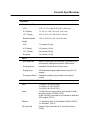
General Specifications
PHYSICAL
Size (H x W x D)
CPU
2.74" x 7.75" x 9.45” (6.95 x 19.7 x 24.0 cm)
8.4" Display
7.1" x 9.1" x 1.69” (18.1 x 23.1 x 4.3 cm)
12.1" Display
10.6" x 12.2" x 2.2” (26.9 x 31 x 5.6 cm)
Backlit Keyboard
1.26" x 12.60" x 8” (3.2 x 32 x 20.3 cm)
Weight
CPU
7.7 pounds (3.5 Kg)
8.4" Display
3.3 pounds (1.5 Kg)
12.1" Display
8.4 pounds (3.8 Kg)
Keyboard
2.2 pounds (1.0 Kg)
INPUT
Main Keyboard
QWERTY style layout, 85 total keys, 12 function keys,
spill resistant, backlight illuminated, USB interface
Pointing Device
Integrated Touch-Pad and Touch screen
Display Keys
6/8 illuminated programmable function keys (8.4”/12”
display)
Emergency Button
Dedicated emergency key located on the display
module
COMMUNICATIONS / EXPANSION PORTS
USB
1 x USB 1.1 on CPU (F5206)
2 x USB 2.0 on CPU (F5207)
3 x USB 2.0 on CPU (F5217)
Serial
3 X RS-232 ports: one external, two internal for WAN
and GPS support (F5206 & F5207)
4x RS-232 ports: two external, two internal for WAN and
GPS support (F5217)
Ethernet
1 X 100 BaseT both 10 & 100 Mbps (F5206 & F5207)
3 x 100 BaseT (F5217)
PC Card Slots
External Type II and internal CF (for WLAN radio in
F5206)
44
MW 800 Vehicle Installation Guide
PCI (F5207 & F5217) Internal Mini PCI (used for WLAN radio)
Video Input
1 X standard Composite video input (CVBS) port, (PAL
or NTSC)
Sound
Two 0.5 W speakers with adjustable volume on 12.1"
display
One 0.5 W speaker with adjustable volume on 8.4"
display
Line out (non-amplified) for external speaker
External microphone in
Primary Display
Interface
RGB, USB, 2-line audio out (balanced, non-amplified)
Secondary Display
Interface
F5206 - RGB, USB, 2-line audio out (balanced, nonamplified)
F5207 - RGB or DVI, USB, 2-line audio out (balanced,
non-amplified)
Firewire 400
One IEEE 1394
Aux Port
F5206 - 2x general purpose inputs; 2x general purpose
outputs; ignition sense; 12V battery voltage out (2A) and
5V DC out (2A)
F5207 - 2x general purpose inputs; 2x general purpose
outputs; ignition sense; 12V battery voltage out (1A) and
5V DC out (1A); USB 2.0; Audio In/Out
F5217 - 2x general purpose inputs; 2x general purpose
outputs; ignition sense; 12V battery voltage out (1A) and
5V DC out (1A); Speed and Direction signals
COMPUTER
Processor
F5206 - Intel® Pentium® 4-M 1.7 GHz
Intel Pentium 4-M 2.2 GHz
Intel Celeron® 1.8 GHz
F5207 & F5207 - Intel Pentium-M processor 745; 1.8
GHz, 2MB cache
Intel Pentium-M processor 715; 1.5
GHz, 2MB cache
Intel Celeron-M processor 320; 1.3
GHz
General Specifications
45
VGA Controller
16 MB (F5206), 32 MB (F5207 & F5217) internal video
RAM
Video Capture
Conexant BT878A
Power Management
Embedded controller supports intelligent thermal and
power management.
Mass Storage
Removable Hard Disk: 40 GB (60 GB optional) with
three dimensional Shock absorber, with heater
2/4 GB Flash Disk available as an alternate to the Hard
Drive
Internal Memory
Optional: 256 MB, 512 MB or 1GB DDRAM
Operating System
Supports Microsoft Windows 2000 and XP Pro
DISPLAY WITH THERMAL PROTECTION MECHANISM
LCD Type
Color Active Matrix, TFT transmissive
LCD Size
12.1" Diagonal XGA or SVGA
8.4" Diagonal SVGA
Resolution
1024 x 768 XGA LCD panel /
800 x 600 SVGA LCD panel
LCD Luminance
Standard SVGA: 300/350 NIT(cd/sq.m)
High-bright XGA: 1200 NIT (cd/sq.m)
Standard Touch
screen
8 Wire Resistive, tempered glass with anti- reflective
coating, impact-proof
COMMUNICATION PROTOCOLS – INTERNAL RADIOS (OPTIONAL)
Private DataTAC
(optional)
Frequency
806-824 MHz Tx, 851-869 MHz Rx
Protocol
RD-LAP 9.6, RD-LAP 19.2
RF Power Output
1.8 Watt into 50-ohm load
GPRS
Frequency
900 MHZ, 1800 MHz, 1900 MHz
Protocol
GPRS packet data
RF Power Output
1.8 Watts at 900 MHz
1 Watt at 1800 MHz and 1900 MHz
iDEN Packet Data
Frequency
806-821 MHz Tx, 851-869 MHz Rx
46
MW 800 Vehicle Installation Guide
Protocol
iDEN (25 kHz spacing)
RF Power Output
0.6 Watts (variable in 6 steps) into 50-Ohm load
GPS
F5206 - Internal Trimble™, SK II
F5207 - F5217 - Internal Trimble™, SQ
F5217 - Internal U-Blox with Dead Reckoning
WLAN
F5206 - IEEE 802.11b, 11 Mbps
F5207 & F5217 - IEEE 802.11b/g, 11/54 Mbps
Bluetooth
Version 1.1 compatible (in 12.1”display model) Supports
data and voice profiles
ENVIRONMENTAL
Operating
Temperature
F5206: -22 to 158°F (–30 to +70°C) for the 1.7 GHz
processor
-22 to 122°F (–30 to +50°C) for all other processors
Notes:
• Performance at extremes include start-ups (with
occasional slight delay due to hard drive heater rampup time) and sustained operations of typical mobile
workstation applications.
• UL certification is available only to 131°F (55°C),
though continued operations are available above this
limit.
• When using 9 VDC battery to power the workstation,
the workstation will not power up if the temperature
range is below -22°F (-30°C)
F5207 & F5217: -22 to 158°F (-30 to +70°C)
Storage Temperature
–40 to 158°F (–40 to +70°C)
Humidity
90 to 95% Relative humidity at 50°C for 8 hours
DURABILITY
Shock
20g peak 1/2 sine wave @ 11ms, 30 impacts
Vibration
Per TIA/EIA 603 Paragraph 3.3.4 and MIL-STD-810F
method 514.5, Fig 514.5C-1
Drip
Per MIL-STD-810F method 506.4 Procedure III
Dust Blowing
Five hours in dust (140 mesh silica flour), laden
atmosphere dust agitation time is for 2 seconds every 15
minutes
Salt Fog
8 hours, 5% Sodium Chloride at 35°C, after exposure,
per MIL-STD-810F 509.4, Procedure I
General Specifications
47
Flammability
Per UL94-HB
Solar Radiation
7 cycles of 24 hours with no functional degradation per
MIL-STD-810F, 505.4, Procedure I
Shock Crash Hazard
75g, 6 ms per MIL-STD-810F method 516.5, Procedure V
ELECTRICAL ENVIRONMENT
Power Source
Vehicle Battery (12 V, negative ground)
Power Range
13.8 VDC ±20%, with no loss of functionality
Electrical Transients
Meets ISO7637-1
Power Consumption
(at 13.8 VDC)
CPU Box
Maximum: 5 A
Typical: 3A (F5206) 1.5 A (F5207 & F5217)
Suspend Mode: 0.7 A (F5206 when fans are not
working)
Suspend Mode: 0.4 A (F5207, F5217)
12.1. XGA Display
Maximum (when heater is not working): 3.5 A
Maximum (when heater is working): 6.5 A
Typical: 3 A
12.1. SVGA Display
Maximum (when heater is not working): 2 A
Maximum (when heater is working): 5 A
Typical: 1.5 A
FCC INFORMATION
GPRS Radio
Acceptance Number: IHDT6AC1
iDEN Packet Data
Radio
Acceptance Number: AZ489FT5796
Private DataTAC
Acceptance Number: PQS-BM28001
WLAN
F5206 Acceptance Number: H9PLA4137
F5207 & F5217 Acceptance Number:
PD9WM3B2200BG
United States
Radiated Emission
FCC Part 15, Class B
Radio Acceptance
FCC Part 90, Part 22, Part 24
Safety
CUL60950-1
48
MW 800 Vehicle Installation Guide
Canada
Radiated Emission
ICES003 (equivalent to FCC Part 15, Class B)
Radio Acceptance
DOC RSS119
Safety
cUL60950-1
Europe
Radiated Emission
EN55022 Class B
Safety
EN60950-1
EMC Immunity
EN50024
R&TTE
EN-301489
eMark
Directive 72/245EC (95/54EC)
Australia
Radiated Emission
AS/NZS 3548 (1995)
Amendment 2 -1997
CISPR 22
Safety
AS/NZS 60950
Specifications subject to change without notice.
HOW TO REACH US:
Government & Enterprise Mobility Solutions
1301 E. Algonquin Road,
Schaumburg, IL 60196
In the USA call: 1-888-567-7347
Outside the USA call: 847-576-5000
Visit our Web site at:
http://www.motorola.com
a
MOTOROLA and the Stylized M Logo are registered in the U.S. Patent and
Trademark Office. All other product or service names are the property of their
respective owners.
Copyright © 2005 Motorola all rights reserved.