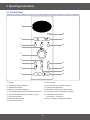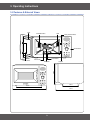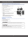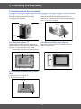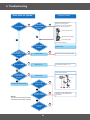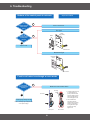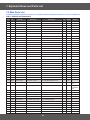
1
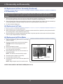
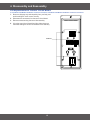
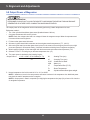
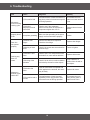
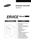
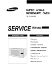
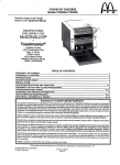
BASIC:
C100R-5U/BWT
MODEL:
C100R-5D
MODEL CODE: C100R-5D/BWT
1. 1.0 cu.ft convection
2. LED - Bar
• Contents
1. Precaution . . . . . . . . . . . . . . . . . . . . . . . . . . . . . . . . . . . . . . . . . . . . . . . . . . . . . . . . . . . . . . . . . . . . . . . . . . . . . . . . . . . . . . . . . . . . 3
1-1 Safety precautions. . . . . . . . . . . . . . . . . . . . . . . . . . . . . . . . . . . . . . . . . . . . . . . . . . . . . . . . . . . . . . . . . . . . . . . . . . . . . . . . . . . 4
1-2 Special High Voltage Precautions . . . . . . . . . . . . . . . . . . . . . . . . . . . . . . . . . . . . . . . . . . . . . . . . . . . . . . . . . . . . . . . . . . . . . . . 5
2. Specifications . . . . . . . . . . . . . . . . . . . . . . . . . . . . . . . . . . . . . . . . . . . . . . . . . . . . . . . . . . . . . . . . . . . . . . . . . . . . . . . . . . . . . . . . . 6
2-1 Table of Specifications. . . . . . . . . . . . . . . . . . . . . . . . . . . . . . . . . . . . . . . . . . . . . . . . . . . . . . . . . . . . . . . . . . . . . . . . . . . . . . . . 6
2-2 Accessory . . . . . . . . . . . . . . . . . . . . . . . . . . . . . . . . . . . . . . . . . . . . . . . . . . . . . . . . . . . . . . . . . . . . . . . . . . . . . . . . . . . . . . . . . 7
3. Operating Instructions . . . . . . . . . . . . . . . . . . . . . . . . . . . . . . . . . . . . . . . . . . . . . . . . . . . . . . . . . . . . . . . . . . . . . . . . . . . . . . . . . . 8
3-1 Control Panel. . . . . . . . . . . . . . . . . . . . . . . . . . . . . . . . . . . . . . . . . . . . . . . . . . . . . . . . . . . . . . . . . . . . . . . . . . . . . . . . . . . . . . . 8
3-2 Features & External Views . . . . . . . . . . . . . . . . . . . . . . . . . . . . . . . . . . . . . . . . . . . . . . . . . . . . . . . . . . . . . . . . . . . . . . . . . . . . 9
4. Disassembly and Reassembly . . . . . . . . . . . . . . . . . . . . . . . . . . . . . . . . . . . . . . . . . . . . . . . . . . . . . . . . . . . . . . . . . . . . . . . . . . . 10
4-1 Replacement of Magnetron, Motor Assembly and Lamp . . . . . . . . . . . . . . . . . . . . . . . . . . . . . . . . . . . . . . . . . . . . . . . . . . . . 10
4-2 Replacement of High Voltage Transformer . . . . . . . . . . . . . . . . . . . . . . . . . . . . . . . . . . . . . . . . . . . . . . . . . . . . . . . . . . . . . . . 10
4-3 Replacement of Door Assembly . . . . . . . . . . . . . . . . . . . . . . . . . . . . . . . . . . . . . . . . . . . . . . . . . . . . . . . . . . . . . . . . . . . . . . . 11
4-3-1 Removal of Door Assembly . . . . . . . . . . . . . . . . . . . . . . . . . . . . . . . . . . . . . . . . . . . . . . . . . . . . . . . . . . . . . . . . . . . . . . 11
4-3-2 Removal of Door “C” . . . . . . . . . . . . . . . . . . . . . . . . . . . . . . . . . . . . . . . . . . . . . . . . . . . . . . . . . . . . . . . . . . . . . . . . . . . 11
4-3-3 Removal of Door “E” . . . . . . . . . . . . . . . . . . . . . . . . . . . . . . . . . . . . . . . . . . . . . . . . . . . . . . . . . . . . . . . . . . . . . . . . . . . 11
4-3-4 Removal of Key Door & Spring . . . . . . . . . . . . . . . . . . . . . . . . . . . . . . . . . . . . . . . . . . . . . . . . . . . . . . . . . . . . . . . . . . . 11
4-3-5 Removal of Screen-Door & Deco-door . . . . . . . . . . . . . . . . . . . . . . . . . . . . . . . . . . . . . . . . . . . . . . . . . . . . . . . . . . . . . 11
4-3-6 Reassembly Test . . . . . . . . . . . . . . . . . . . . . . . . . . . . . . . . . . . . . . . . . . . . . . . . . . . . . . . . . . . . . . . . . . . . . . . . . . . . . . 12
4-4 Replacement of Fuse . . . . . . . . . . . . . . . . . . . . . . . . . . . . . . . . . . . . . . . . . . . . . . . . . . . . . . . . . . . . . . . . . . . . . . . . . . . . . . . 12
4-5 Replacement of Drive Motor . . . . . . . . . . . . . . . . . . . . . . . . . . . . . . . . . . . . . . . . . . . . . . . . . . . . . . . . . . . . . . . . . . . . . . . . . . 12
4-6 Replacement of Control Circuit Board . . . . . . . . . . . . . . . . . . . . . . . . . . . . . . . . . . . . . . . . . . . . . . . . . . . . . . . . . . . . . . . . . . . 13
5. Alignment and Adjustments . . . . . . . . . . . . . . . . . . . . . . . . . . . . . . . . . . . . . . . . . . . . . . . . . . . . . . . . . . . . . . . . . . . . . . . . . . . . . 14
5-1 High Voltage Transformer . . . . . . . . . . . . . . . . . . . . . . . . . . . . . . . . . . . . . . . . . . . . . . . . . . . . . . . . . . . . . . . . . . . . . . . . . . . . 14
5-2 Low Voltage Transformer . . . . . . . . . . . . . . . . . . . . . . . . . . . . . . . . . . . . . . . . . . . . . . . . . . . . . . . . . . . . . . . . . . . . . . . . . . . . 14
5-3 Magnetron . . . . . . . . . . . . . . . . . . . . . . . . . . . . . . . . . . . . . . . . . . . . . . . . . . . . . . . . . . . . . . . . . . . . . . . . . . . . . . . . . . . . . . . . 14
5-4 High Voltage Capacitor . . . . . . . . . . . . . . . . . . . . . . . . . . . . . . . . . . . . . . . . . . . . . . . . . . . . . . . . . . . . . . . . . . . . . . . . . . . . . . 15
5-5 High Voltage Diode . . . . . . . . . . . . . . . . . . . . . . . . . . . . . . . . . . . . . . . . . . . . . . . . . . . . . . . . . . . . . . . . . . . . . . . . . . . . . . . . . 15
5-6 Main Relay and Power Control RelayA . . . . . . . . . . . . . . . . . . . . . . . . . . . . . . . . . . . . . . . . . . . . . . . . . . . . . . . . . . . . . . . . . . 15
5-7 Adjustment of Primary Switch, Door Sensing Switch and Monitor Switch. . . . . . . . . . . . . . . . . . . . . . . . . . . . . . . . . . . . . . . . 15
5-8 Output Power of Magnetron . . . . . . . . . . . . . . . . . . . . . . . . . . . . . . . . . . . . . . . . . . . . . . . . . . . . . . . . . . . . . . . . . . . . . . . . . . 16
5-9 Procedure for Measurement of Microwave Energy Leakage . . . . . . . . . . . . . . . . . . . . . . . . . . . . . . . . . . . . . . . . . . . . . . . . . 17
5-10 Check for Microwave Leakage . . . . . . . . . . . . . . . . . . . . . . . . . . . . . . . . . . . . . . . . . . . . . . . . . . . . . . . . . . . . . . . . . . . . . . . 17
5-11 Note on Measurement . . . . . . . . . . . . . . . . . . . . . . . . . . . . . . . . . . . . . . . . . . . . . . . . . . . . . . . . . . . . . . . . . . . . . . . . . . . . . . 17
5-12 Leakage Measuring Procedure . . . . . . . . . . . . . . . . . . . . . . . . . . . . . . . . . . . . . . . . . . . . . . . . . . . . . . . . . . . . . . . . . . . . . . . 17
5-12-1 Record keeping and notification after measurement . . . . . . . . . . . . . . . . . . . . . . . . . . . . . . . . . . . . . . . . . . . . . . . . . . 17
5-12-2 At least once a year have the microwave energy survey meter checked for accuracy by its manufacturer. . . . . . . . . 17
6. Troubleshooting . . . . . . . . . . . . . . . . . . . . . . . . . . . . . . . . . . . . . . . . . . . . . . . . . . . . . . . . . . . . . . . . . . . . . . . . . . . . . . . . . . . . . . 18
6-1 Electrical Malfunction . . . . . . . . . . . . . . . . . . . . . . . . . . . . . . . . . . . . . . . . . . . . . . . . . . . . . . . . . . . . . . . . . . . . . . . . . . . . . . . 18
6-2 Unsatisfactory Cooking . . . . . . . . . . . . . . . . . . . . . . . . . . . . . . . . . . . . . . . . . . . . . . . . . . . . . . . . . . . . . . . . . . . . . . . . . . . . . . 22
6-3 Part Check List . . . . . . . . . . . . . . . . . . . . . . . . . . . . . . . . . . . . . . . . . . . . . . . . . . . . . . . . . . . . . . . . . . . . . . . . . . . . . . . . . . . . 22
7. Exploded Views and Parts List . . . . . . . . . . . . . . . . . . . . . . . . . . . . . . . . . . . . . . . . . . . . . . . . . . . . . . . . . . . . . . . . . . . . . . . . . . 23
7-1 Exploded Views . . . . . . . . . . . . . . . . . . . . . . . . . . . . . . . . . . . . . . . . . . . . . . . . . . . . . . . . . . . . . . . . . . . . . . . . . . . . . . . . . . . . 23
7-2 Main Parts List. . . . . . . . . . . . . . . . . . . . . . . . . . . . . . . . . . . . . . . . . . . . . . . . . . . . . . . . . . . . . . . . . . . . . . . . . . . . . . . . . . . . . 24
7-3 Door Parts List. . . . . . . . . . . . . . . . . . . . . . . . . . . . . . . . . . . . . . . . . . . . . . . . . . . . . . . . . . . . . . . . . . . . . . . . . . . . . . . . . . . . . 26
7-4 Control Parts List . . . . . . . . . . . . . . . . . . . . . . . . . . . . . . . . . . . . . . . . . . . . . . . . . . . . . . . . . . . . . . . . . . . . . . . . . . . . . . . . . . . 27
7-5 Casing Parts List . . . . . . . . . . . . . . . . . . . . . . . . . . . . . . . . . . . . . . . . . . . . . . . . . . . . . . . . . . . . . . . . . . . . . . . . . . . . . . . . . . . 28
7-6 Standard Parts List . . . . . . . . . . . . . . . . . . . . . . . . . . . . . . . . . . . . . . . . . . . . . . . . . . . . . . . . . . . . . . . . . . . . . . . . . . . . . . . . . 29
8. Schematic Diagrams . . . . . . . . . . . . . . . . . . . . . . . . . . . . . . . . . . . . . . . . . . . . . . . . . . . . . . . . . . . . . . . . . . . . . . . . . . . . . . . . . . . 30
8-1. Schematic Diagrams . . . . . . . . . . . . . . . . . . . . . . . . . . . . . . . . . . . . . . . . . . . . . . . . . . . . . . . . . . . . . . . . . . . . . . . . . . . . . . . 30
9. Electrical Parts List . . . . . . . . . . . . . . . . . . . . . . . . . . . . . . . . . . . . . . . . . . . . . . . . . . . . . . . . . . . . . . . . . . . . . . . . . . . . . . . . . . . . 31
9-1. Electrical Parts List . . . . . . . . . . . . . . . . . . . . . . . . . . . . . . . . . . . . . . . . . . . . . . . . . . . . . . . . . . . . . . . . . . . . . . . . . . . . . . . . . 31
10. Wiring Diagrams . . . . . . . . . . . . . . . . . . . . . . . . . . . . . . . . . . . . . . . . . . . . . . . . . . . . . . . . . . . . . . . . . . . . . . . . . . . . . . . . . . . . . 33
10-1 Wiring Diagrams . . . . . . . . . . . . . . . . . . . . . . . . . . . . . . . . . . . . . . . . . . . . . . . . . . . . . . . . . . . . . . . . . . . . . . . . . . . . . . . . . . 33
11. Reference . . . . . . . . . . . . . . . . . . . . . . . . . . . . . . . . . . . . . . . . . . . . . . . . . . . . . . . . . . . . . . . . . . . . . . . . . . . . . . . . . . . . . . . . . . . 34
11-1 Model name standard . . . . . . . . . . . . . . . . . . . . . . . . . . . . . . . . . . . . . . . . . . . . . . . . . . . . . . . . . . . . . . . . . . . . . . . . . . . . . . 34
11-2 Customer inquiry cases and countermeasures . . . . . . . . . . . . . . . . . . . . . . . . . . . . . . . . . . . . . . . . . . . . . . . . . . . . . . . . . . . 35
2
1. Precaution
3
1. Precaution
Follow these special safety precautions. Although the microwave oven is completely safe during ordinary use,
repair work can be extremely hazardous due to possible exposure to microwave radiation, as well as potentially
lethal high voltages and currents.
1-1 Safety precautions (
)
1.
13. Design Alteration Warning: Use exact replacement
parts only, i.e.,only those that are specified in
thedrawings and parts lists of this manual. This
is especially important for the Interlock switches,
described above. Never alter or add to the
mechanical or electrical design of the MWO.
Any design changes or additions will void the
manufacturer’s warranty. Always unplug the unit’s
AC power cord from the AC power source before
attempting to remove or reinstall any component or
assembly.
14. Never defeat any of the B+ voltage interlocks. Do not
apply AC power to the unit (or any of its assemblies)
unless all solid-state heat sinks are correctly
installed.
15. Some semiconductor (“solid state”) devices
are easily damaged by static electricity. Such
components are called Electrostatically Sensitive
Devices (ESDs). Examples include integrated
circuits and field-effect transistors. Immediately
before handling any semiconductor components or
assemblies, drain the electrostatic charge from your
body by touching a known earth ground.
16. Always connect a test instrument’s ground lead to
the instrument chassis ground before connecting the
positive lead; always remove the instrument’s ground
lead last.
17. When checking the continuity of the witches or
transformer, always make sure that the power is
OFF, and one of the lead wires is disconnected.
18. Components that are critical for safety are indicated
in the circuit diagram by shading, or .
19. Use replacement components that have the same
ratings, especially for flame resistance and dielectric
strength specifications. A replacement part that does
not have the same safety characteristics as the
original might create shock, fire or other hazards.
NOTE : Connect the oven to a 20A. When
connecting the oven to a 15A,make sure that circuit
breaker can operate.
All repairs should be done in accordance with the
procedures described in this manual. This product
complies with Federal Performance Standard 21
CFR
2. Microwave emission check should be performed to
prior to servicing if the oven is operative.
3. If the oven operates with the door open :Instruct
the user not to operate the oven and contact
the manufacturer and the center for devices and
radiological health immediately.
4. Notify the Central Service Center if the microwave
leakage exceeds 5 mW/cm2.
5. Check all grounds.
6. Do not power the MWO from a “2-prong” AC cord.
Be sure that all of the built-in protective devices are
replaced. Restore any missing protective shields.
7. When reinstalling the chassis and its assemblies,
be sure to restore all protective devices, including:
nonmetallic control knobs and compartment covers.
8. Make sure that there are no cabinet openings
through which people --particularly children--might
insert objects and contact dangerous voltages.
Examples: Lamp hole,ventilation slots.
9. Inform the manufacturer of any oven foundto have
emission in excess of 5 mW/cm2 ,Make repairs to
bring the unit into compliance at no cost to owner
and try to determine cause. Instruct owner not to use
oven until it has been brought into compliance.
CENTRAL SERVICE CENTER
10. Service technicians should remove their watches
while repairing an MWO.
11. To avoid any possible radiation hazard,replace parts
in accordance with the wiring diagram. Also, use
only the exact replacements for the following parts:
Primary and secondary interlock switches, interlock
monitor switch.
12. If the fuse is blown by the Interlock Monitor Switch:
Replace all of the following at the same time:
Primary, door sensing switch and power relay, as
well as the Interlock Monitor Switch. The correct
adjustment of these switches is described elsewhere
in this manual. Make sure that the fuse has the
correct rating for the particular model being repaired.
4
1. Precaution
1-2 Special High Voltage Precautions
1.
2.
3.
High Voltage Warning Do not attempt to measure any
of the high voltages --this includes the filament voltage
of the magnetron. High voltage is present during any
cook cycle. Before touching any components or wiring,
always unplug the oven and discharge the high voltage
capacitor (See Figure 1-1)
The high-voltage capacitor remains charged about
30 seconds after disconnection. Short the negative
terminal of the high-voltage capacitor to to the oven
chassis. (Use a screwdriver.)
High voltage is maintained within specified limits
by close-tolerance, safety-related components and
adjustments. If the high voltage exceeds the specified
limits, check each of the special components.
H. V. Capacitor
Short
Touch chassis ground first then short to the
high voltage capacitor terminal by using
screwdriver or jumper wire.
There exists HIGH VOLTAGE ELECTRICITY with high current capabilities in the circuits of the HIGH
VOLTAGE TRANSFORMER secondary and filament terminals. It is extremely dangerous to work on or near
these circuits with the oven energized.
DO NOT measure the voltage in the high voltage circuit including filament voltage of magnetron.
Never touch any circuit wiring with your hand nor
with uninsulated tool during operation.
Servicemen should remove their watches
whenever working close to or replacing the
magnetron.
5
2. Specifications
2-1 Table of Specifications
Items
Model
Sub Items
C100R-5D
Power source
C100R-5U
230 V ~ 50 Hz AC
230 V ~ 50 Hz AC
Maximum Power
3100 W
3100 W
Microwave
1400 W
1400 W
Grill
1300 W
1300 W
Convection
1700 W
1700 W
Output Power
100 W / 900 W
100 W / 900 W
Operating Frequency
2450 MHz
2450 MHz
Outside
517 x 511 x 310 mm
517 x 516 x 310 mm
Oven cavity
336 x 346 x 222 mm
352 x 348 x 235 mm
1.0 CU. FT
1.0 CU. FT
Shipping
24.5 Kg approx
22.5 Kg approx
Net
22.5 Kg approx
19 Kg approx
Power
comsumption
Dimension (W x D
xH)
Volume
Weight
6
2. Specifications
2-2 Accessory
Item
Description
Code No.
Q’ty
Coupler
DE67-00182A
1
ASSY-GUIDE ROLLER
DE97-00222A
1
TRAY-COOKING
DE74-20015G
1
ASSY-WIRE RACK
DE97-00216E
1
ASSY-WIRE RACK
DE97-00136B
1
7
3. Operating Instructions
3-1 Control Panel
1
10
2
11
3
4
12
5
6
7
13
8
14
15
9
1.
2.
3.
4.
5.
6.
7.
8.
9.
16
Display
Auto defrost feature selection
Standing time setting
Memory cook feature selection
Time setting weight selection and recipe selection
Combined mode selection (microwave + grill)
Grill mode selection
preheat mode selection
Stop / cabcel button
10. Clock setting
11. Auto reheat & Cook feature selection
12. Cooking time adjustment
13. Microwave / Power level mode selection
14. Convection mode / Temperature selection
15. Combined mode selection
(microwave + convection)
16. Start / cooking time adjustment button
8
3. Operating Instructions
3-2 Features & External Views
Door
Ventilation Holes
Light
Safety Interlock Holes
Control Pane
Coupler
Grill Rack
310mm
Door Latches
Guide Roller
Glass Plate
346mm
336mm
517mm
511mm
�����
9
4. Disassembly and Reassembly
4-1 Replacement of Magnetron, Motor Assembly and Lamp
Remove the magnetron including the shield case, permanent magnet, choke coils and capacitors (all of which
are contained in one assembly).
1. Disconnect all lead wires from the magnetron and lamp.
2. Remove a screw securing air cover.
Thermo S/W
Cover Air
3. Remove the air cover.
4. Remove screws securing the magnetron to the wave
guide.
5. Take out the magnetron very carefully.
Fan Motor
6. Remove tow from the back panel of fan motor
assembly.
7. Take out the fan motor assembly.
Magnetron
8. Remove the oven lamp by rotating to pull out from hole of
air cover.
NOTE1: When removing the magnetron, make sure that
its antenna does not hit any adjacent parts, or it may be
damaged.
NOTE2: When replacing the magnetron, be sure to
Screw
H. V. Trans
remount the magnetron gasket in the correct position and
H.V Capacitor
make sure the gasket is in good condition.
4-2 Replacement of High Voltage
Transformer
1.
2.
3.
4.
Discharge the high voltage capacitor.
Disconnect all the leads.
Remove the mounting bolts.
Reconnect the leads correctly and firmly.
Servicemen should remove their watches whenever working close to or replacing the magnetron.
There exists HIGH VOLTAGE ELECTRICITY with high current capabilities in the circuits of the
HIGHVOLTAGE TRANSFORMER secondary and filament terminals. It is extremely dangerous to work on
or near these circuits with the oven energized.
DO NOT measure the voltage in the high voltage circuit including filament voltage of magnetron.
10
Screws
4. Disassembly and Reassembly
Low Hinge
Low Hinge
4-3 Replacement of Door
Assembly
Screws
Spring Screws
Key Door
4-3-1 Removal of Door Assembly
4-3-2 Removal of Door “C”
Securing the upper hinge and lower hinge.
The remove door assembly
Insert flat screwdriver into the gap between Door “A”
and Door “C” to remove Door “C” Be caful when handing
Door “C” because it is fragile
Upper Hinge
Door "C"
Screws
Deco-Door
Door "E"
Upper Hinge
Deco-Door
Door "C"
Door "E"
Screws
Low Hinge
Key Door
Screws
Door
"A"
Low Hinge
Key Door
Screws
4-3-3 Removal of Door “E”
Spring
4-3-4 Removal of Key Door & Spring
Following the procedure as shown in the figure,
insert and bend a thin metal plate between Door “E”
and Door “A” until you hear the ‘tick’ sound.
•
Insertion depth of the
Doorthin
"C" metal plate should be
Door "E"
Spring Door "A"
Remove pin hinge grom Door “E” Datach spring from
Door “E” and key door
Deco-Door
Deco-Door
Door "C"
Door "E"
Door "A"
Door "A"
4-3-5 Removal of Screen-Door & Decodoor
�����
�����
1. Remove Door “E” from Door “A”
Door “B”
"E"
2. Remove Door-screen
Upper Hinge
Door "E"
Door "E"
Key Door
Screws
Spring
�����
�����
Deco-Door
11
4. Disassembly and Reassembly
4-3 Replacement of Door Assembly (Continued)
4-3-6 Reassembly Test
After replacement of the defective component parts of the door, reassemble it and follow the
instructions below for proper installation and adjustment so as to prevent an excessive microwave
leakage.
1.
2.
3.
When mounting the door to the oven, be sure to adjust the door parallel to the bottom line of the oven face plate
by moving the upper hinge and lower hinge in the direction necessary for proper alignment.
Adjust so that the door has no play between the inner door surface and oven front surface. If the door assembly is
not mounted properly, microwave energy may leak from the space between the door and oven.
Do the microwave leakage test.
4-4 Replacement of Fuse
1.
2.
3.
Disconnect the oven from the power source.
When 12A fuse blows out by the operation of interlock monitor switch failure, replace the primary interlock switch,
door sensing switch, monitor switch and power relay.
When the above three switches operate properly, check if any other part such as the control circuit board, blower
motor or high voltage transformer is defective.
4-5 Replacement of Drive Motor
1.
2.
3.
4.
5.
6.
7.
8.
Take out the glass tray, guide roller from oven cavity,
disconnect power.
Remove turn table motor cover from case bottom.
CAUTION : Remove sharp edge after cover
removal.
Disconnect leads from motor.
Remove the screws securing motor to bottom of
over cavity and lift out the motor.
When replacing the motor, be sure to remount it in
the correct position.
NOTE : The shaft of motor should fit tip coupler.
Screw the motor to bottom of oven cavity.
Connect leads to the drive motor.
Screw the drive motor cover to the base plate with a
screw driver.
NOTE : Bring the spare screw from service center.
Screw
Drive Motor
Base Plate
Drive Motor Cover
COVER FIXING SCREW : MATCHINE SCREW(6006-001170)
12
4. Disassembly and Reassembly
4-6 Replacement of Control Circuit Board
1.
2.
3.
4.
Be sure to dislyarge any static electricity from your body, and
avoid touching the “touch control” circuitry
Disconnect the connectors from the control circuit board.
Remove screws securing the control box assembly.
Lift up the control circuit board from right side and remove
the hooks holding the control circuit board to box assembly
SCREWS
13
5. Alignment and Adjustments
1. High voltage is present at the high voltage terminals during any cook cycle.
2. It is neither necessary nor advisable to attempt measurement of the high voltage.
3. Before touching any oven components or wiring, always unplug the oven from its power source and
discharge the high voltage capacitor.
5-1 High Voltage Transformer
1.
2.
Remove connectors from the transformer terminals and
check continuity.
Normal resistance readings are as follows:
Secondary
Approx. 162Ω
Filament
Approx. 0Ω
Primary
Approx. 2.14Ω
Filament Terminals
Secondary
Terminal
Primary
Terminals
(Room temperature = 20°C)
5-2 Low Voltage Transformer
1.
2.
3.
The low voltage transformer is located on the control circuit board.
Remove the low voltage transformer from the PCB Ass’y and check continuity.
Normal resistor reading is shown in the table.
Terminals
Resistance
1~2(Input)
290Ω.
3~4(Output)
4.0Ω.
5~6(Output)
1.0Ω.
5-3 Magnetron
1.
2.
3.
4.
Continuity checks can indicate only an open filament or
a shorted magnetron. To diagnose an open filament or
shorted magnetron.
Isolate the magnetron from the circuit by disconnecting its
leads.
A continuity check across the magnetron filament terminals
should indicate one ohm or less.
A continuity check between each filament terminal and
magnetron case should read open.
14
Magnetron Antenna
Gasket Plate
Cooling Fins
5. Alignment and Adjustments
5-4 High Voltage Capacitor
1.
2.
3.
4.
5.
Check continuity of the capacitor with the meter set at the highest resistance scale.
Once the capacitor is charged, a normal capacitor shows continuity for a short time, and then indicates 9MΩ.
A shorted capacitor will show continuous continuity.
An open capacitor will show constant 9MΩ.
Resistance between each terminal and chassis should read infinite.
5-5 High Voltage Diode
1.
2.
Isolate the diode from the circuit by disconnecting its leads.
With the ohm-meter set at the highest resistance scale, measure across the diode terminals. Reverse the meter
leads and read the resistance. A meter with 6V, 9V or higher voltage batteries should be used to check the front-to
back resistance of the diode (otherwise an infinite resistance may be read in both directions). The resistance of a
normal diode will be infinite in one direction and several hundred KΩ in the other direction.
5-6 Main Relay and Power Control RelayA
1.
2.
3.
The relays are located on the PCB Ass’y. Isolate them from the main circuit by disconnecting the leads.
Operate the microwave oven with a water load in the oven. Set the power level set to high.
Check continuity between terminals of the relays after the start pad is pressed.
5-7 Adjustment of Primary Switch, Door Sensing Switch and Monitor Switch
For continued protection against radiation hazard, replace parts in accordance with the wiring diagram
and be sure to use the correct part number for the following switches: Primary and secondary interlock
switches, and the interlock monitor switch (replace all together). Then follow the adjustment procedures
below. After repair and adjustment, be sure to check the continuity of all interlock switches and the interlock
monitor switch.
1.
2.
3.
4.
5.
6.
When mounting Primary switch and Interlock Monitor
switch to Latch Body, consult the figure.
No specific adjustment during installation of Primary switch
and Monitor switch to the latch body is necessary.
When mounting the Latch Body to the oven assembly,
adjust the Latch Body by moving it so that the oven door
will not have any play in it. Check for play in the door by
pulling the door assembly. Make sure that the latch keys
move smoothly after adjustment is completed. Completely
tighten the screws holding the Latch Body to the oven
assembly.
Reconnect to Monitor switch and check the continuity of
the monitor circuit and all latch switches again by following
the components test procedures.
Confirm that the gap between the switch housing and
the switch actuator is no more than 0.5mm when door is
closed.
Interlock Switch Replacement - When replacing faulty
switches, be sure switch mounting tabs are not bent,
broken or otherwise deficient in their ability to secure the
switches in place.
15
Primary Interlock Switch
Interlock Monitor
Switch
Body Latch
Primary Interlock switch
Monitor switch(COM-NC)
Door Sensing S/W
(Secondary interlock)
Lever Door(B)
Door Sensing
Switch
Door Open Door Closed
∞
0
0
∞
∞
0
∞
0
5. Alignment and Adjustments
5-8 Output Power of Magnetron
MICROWAVE RADIATION
PERSONNEL SHOULD NOT ALLOW EXPOSURE TO MICROWAVE RADIATION FROM MICROWAVE
GENERATOR OR OTHER PARTS CONDUCTING MICROWAVE ENERGY.
The output power of the magnetron can be measured by performing a water temperature rise test.
Equipment needed :
•
Two 1-liter cylindrical borosilicate glass vessel (Outside diameter 190 mm)
•
One glass thermometer with mercury column
NOTE: Check line voltage under load. Low voltage will lower the magnetron output. Make all temperature and
time tests with accurate equipment.
1. Fill the one liter glass vessel with water.
2. Stir water in glass vessel with thermometer, and record glass vessel’s temperature (“T1”, 10±1°C).
3. After moving the water into another glass vessel, place it in the center of the cooking tray. Set the oven to high
power and operate for 50 seconds exactly. (3 seconds included as a holding time of magnetron oscillation:)
4. When heating is finished, stir the water again with the thermometer and measure the temperature (“T2”).
5. Subtract T1 from T2. This will give you the water temperature rise. (∆T)
6. The output power is obtained by the following formula;
Output Power =
7.
4.187 x 1000 x ∆T+0.55xMcx(T2 -T1)
50
: Heating Time (sec)
47
: Counting Time (sec)
47
4.187 : Coefficient for Water
1000 : Water (cc)
∆T
: Temperature Rise (T2-T1)
To
: Room Temperature
Mc
: Cylindrical borosilicate glass weight
Normal temperature rise for this model is 9°C to 11°C at ‘HIGH’.
NOTE 1: Variations or errors in the test procedure will cause a variance in the temperature rise. Additional power
test should be made if temperature rise is marginal.
NOTE 2: Output power in watts is computed by multiplying the temperature rise (step 5) by a factor of 91 times the
of centigrade temperature.
16
5. Alignment and Adjustments
5-9 Procedure for Measurement of Microwave Energy Leakage
1.
2.
3.
4.
5.
Pour 275±15cc of 20±5°C(68±9°F) water in a beaker which is graduated to
600cc, and place the beaker in the center of the oven.
Start to operate the oven and measure the leakage by using a microwave
energy survey meter.
Set survey meter with dual ranges to 2,450MHz.
When measuring the leakage, always use the 2 inch spacer cone with the
probe. Hold the probe perpendicular to the cabinet door. Place the spacer
cone of the probe on the door and/or cabinet door seam and move along
the seam, the door viewing window and the exhaust openings moving the
probe in a clockwise direction at a rate of 1 inch/sec. If the leakage testing of the cabinet door seam is taken near
a corner of the door, keep the probe perpendicular to the areas making sure that the probe end at the base of the
cone does not get closer than 5cm to any metal. If it gets closer than 5cm, erroneous readings may result.
Measured leakage must be less than 4mW/cm2 , after repair or adjustment.
Maximum allowable leakage is 5mW/cm2 .
4mW/cm2 is used to allow for measurement and meter accuracy
5-10 Check for Microwave Leakage
1.
2.
3.
4.
5.
Remove the outer panel.
Pour 275±15cc of 20±5°C(68±9°F) water in a beaker which is graduated to 600cc,
and place the beaker in the center of the oven.
Start the oven at the highest power level.
Set survey meter dual ranges to 2,450MHz.
Using the survey meter and spacer cone as described above, measure near the
opening of magnetron, the surface of the air guide and the surface of the wave
guide as shown in the following photo.( but avoid the high voltage components.)
The reading should be less than 4mW/cm2 .
5-11 Note on Measurement
1.
2.
3.
4.
Do not exceed the limited scale.
The test probe must be held on the grip of the handle, otherwise a false reading may result when the operator’s
hand is between the handle and the probe.
When high leakage is suspected, do not move the probe horizontally along the oven surface; this may cause
damage to the probe.
Follow the recommendation of the manufacturer of the microwave energy survey meter.
5-12 Leakage Measuring Procedure
5-12-1 Record keeping and notification after measurement
1) After adjustment and repair of a radiation preventing device, make a repair record for the measured values, and
keep the data.
2) If the radiation leakage is more than 4mW/cm2 after determining that all parts are in good condition, functioning
properly and the identical parts are replaced as listed in this manual notify that fact to ;
CENTRAL SERVICE CENTER
5-12-2 At least once a year have the microwave energy survey meter checked for
accuracy by its manufacturer.
17
6. Troubleshooting
WARNING FOR HIGH VOLTAGE
4000 VOLTS EXIST AT THE HIGH VOLTAGE AREA. DO NOT OPERATE THE OVEN WITH CABINET PARTS
REMOVED. DO NOT REMOVE THE CABINET PARTS IF THE POWER SUPPLY CORD IS PLUGGED IN
THE WALL OUTLET. UNPLUG THE POWER CORD BEFORE SERVICING.
6-1 Electrical Malfunction
Parts
Fuse blows
out when
door is
opened.
Fuse is
Open
Oven lamp
does not
light.
Fan does
not operate.
Cause
Diagnosis
Remedy
Defective primary
interlock switch
are winding.
Check continuity of the primary switch
terminals with wire removed using a
multimeter. If there is continuity inter
between switch terminals when door is
opened,the switch is defective.
Replace the primary
interlock switch
Defective in terlock
monitor switch
Check continuity of the monitor switch
terminals with wire removed by using a
multimeter. If there is continuity between
switch terminals the door is closed, the
switch is defective.
Replace the interlock
monitor switch
Layer short of the
secondary coil of
H. V. Transformer
The fuse will not blow right away, but if it
blows in a few seconds, then there is a
layer short If the fuse blows with H. V. Trans
secondary open, the transformer may be
faulty.
Replace
H.V.Transformer
1) Fuse blown out
Check fuse.
Replace the fuse.
2) Poor contact of
power cord.
Check continuity of power supply cord. Also
check whether the power cord is securely
wired.
Adjust or replace the
power supply cord
3) Defective lamp
The fan motor rotates, but lamp does not
light.
Replace the lamp.
4) Defective timer
contacts
Check the terminals of timer for continuity,
turning the timer knob ON and OFF
repeatedly.
Replace the timer.
5) Thermal cutout
S/W open
In this case the oven lamp and fan do not
turn on
Replace the thermal
cutout S/W
1) Defective fan
motor.
If 230V is found at motor terminals, the
motor should be replaced.
Replace the motor.
2) Defective con
tacts of timer
The oven lamp does not light and fan motor
does not operate.
Replace the timer.
NOTE: Interlock monitor switch must be replaced when the fuse is blown out.
18
6. Troubleshooting
part
Microwave
turns off during
cooking cycle.
properly shock
is felt.
Door doe
not operate
properly
Cooking tray
does not
rotate.
Magnetron
thermal cutout
switch OFF
Cause
Diagnosis
Remedy
1) Too small a load
If a small amount of food is heated for a
long time, period of microwave may turn
off during operation.
To increase the oven
water into water into the
oven.
2) Defective
magnetron thermal
cutout S/W
Check to see if the magnetron
thermal cutout switch is activated at a
temperature higher than 150 ºC.
Replace thermal cutout
switch.
Incomplete grounding
Make sure that qrounding of the power
supply cord has been done properly.
Rewire.
1) Broken door
hinges
Remove the cabinet for inspection.
Check the door hinge.
Replace door hinges.
2) Missing or loose
screw
Check if the screws are secured well to
the door hinge.
Fasten or tighten.
1) Defective drive
motor
Check to see if 21V exists at the motor
terminals.If so, motor will be defective.
Replace drive motor.
1) Blocking of the
ventilatior
Check if the air inlet or outlet ventilation
is blocked by the wall or other objects.
Keep a distance of
100mm from the wall or
the objects.
2) Defective fan
motor
If the fan motor does not operate with
230V applied to the terminal, the motor
may be faulty.
Replace fan motor.
3) Too small a load or
no load
If a small amount of food is heated
repeatedly over a long period of time,
microwave turns off during operation.
To increase the oven
load, place a glass of
water into the oven.
19
6. Troubleshooting
Oven does not operate.
Is Fuse OK?
NO
*Inspection method
Is Primary
interlock switch
normal?
NO
Make sure to inspect the power
relay after replacing primary
interlock switch, secondary interlock
switch and door sensing switch.
Primary interlock switch
YES
Secondary interlock switch
Door sensing switch
YES
*Latch switch assembly
Is Power Relay
normal?
Is the
magnetron
temperature switch
normal?
Replace Relay
NO
NO
Replace switch
Check a fan motor after replacing switch
Replace L.V.T.
Check PCB after replacing L.V.T.
YES
Is L.V.T normal?
NO
YES
Power Point Check Point
Is the IC01
output of PCB
normal?
NO
Replace PCB.
YES
Checking high voltagecircuits
Is high voltage
diode normal?
NO
YES
Caution
1.Be careful of high voltage circuits.
2. Discharge high voltage capacitor.
Is high voltage
capacitor normal?
NO
YES
Is magnetron
normal?
20
NO
In case any of high voltage parts is
damaged, check all parts related to
high votlage.
6. Troubleshooting
Buttons of the control panel do not work.
Are
buttons pressed
in the correct
order?
*Inspection method
NO
Refer to User Manual
Tact Type
YES
Is the
connector of the
control panel
normal?
Switch
(Tact Switch)
NO
Button
YES
Replace PCB.
Connector
Membrane Type
Membrane
Switch
Connector
Food is not heated even though an oven works.
Is the latch
switch operating
normally?
NO
Method to control latch switch
Securing
nuts
YES
Door Key
Checking high voltage circuits
1. Loosenly tighten the nuts
to check whether the
primary interlock switch
works by slightly moving
latches to right and left.
Then firmly tighten nuts.
2. Check whether the
secondary interlock
switch and door sensing
switch work by slightly
moving latches to right
and left, then firmly
tighten nuts.
Refer to "Checking high voltage circuits"
on the previous page.
*Door open
21
*Door closed
6. Troubleshooting
6-2 Unsatisfactory Cooking
Parts
Food is
not
heated.
Cause
Diagnosis
Remedy
1) Open cathode
of magnetron
Check the terminals with a multimeter to see
if the heater circuit is open.
Replace magnetron.
2) Defective H. V.
Diode
Check the H. V. Diode for continuity in the
reverse and normal directions using meter. If
there is continuity in the reverse direction, the
H. V. Diode may be faulty. (In this event H. V.
Capacitor will be hot)
Replace H. V.
Diode.
3) Shorted magnetron
Connect megger leads to quick-connect terminal & body of the magnetron if there is continuity, the magnetron may be fuse will be blown)
faulty. (In this case the main fuse will be blown)
Replace magnetron.
4) Defective magnetron
If there is a crack in the magnetron antenna
(dome), the magnetron is defective.
Replace magnetron.
5) Poor contact of
primary interlock switch
Check if the screws are secured well to the
door hinge. and pressing it ON and OFF repeatedly.
Replace or adjust.
6) Open coil of H.
V. Transformer
Check the continuity of primary coil and
secondary coil. If there is no continuity, H. V.
Transformer is defective.
Replace the H. V.
Transformer.
7) Shorted H. V.
capacitor
Check the continuity of capacitor.
If the capacitor shorts, the fuse blows
Replace the H. V.
Capacitor.
8) Monitor Fuse
out
Check the monitor fuse (on the PCB)
Replace the Monitor
fuse
6-3 Part Check List
Symptom
Microwave
cooking does
not work.
Fan motor
does not
rotate.
Related Parts
Check Points
Remedy
H.V.Transformer
1) Check if the primary and secondary coil is open or
shorted.
* Resistance of primary coil: . 1.7Ω Approx.
Resistance of secondary coil: Approx. 142Ω
2) Check if the MGT Heater Voltage is approx. 3.3V AC.
Caution : High voltage !
Replace.
H.V.Capacitor
Check continuity of capacitor between two
terminals with H.V.wire lead removed.
The resistance should be approx. 10MW, it’s failure..
Replace.
H.V.Diode
1) If there is no continuity in forward, direction the
H.V.Diode is open.
2) If there is continuity in reverse direction, it’s shorted.
Replace.
Fan motor
Check if the motor coil is open.
Replace.
22
7. Exploded Views and Parts List
7-1 Exploded Views
M001
W003
M005
P186
W006
M013
M095
M113
M008
M010
M011
M053
M015
M058
H008
M012
M019
W002
M054
P109
H013
M023
T030
T026
H018
M036
T026
T030
M051
T010
T009
B006
M038
M049
T032
B018
B001
M035
B002
B010
M037
T001
B024
B011
T017
M034
M048
M041
M039
M047
M042
M046
23
M045
M040
7. Exploded Views and Parts List
7-2 Main Parts List
(S.N.A : SERVICE NOT AVAILABLE)
Level
No.
1-1
M041
Code No.
1-1
M039
2501-001015
1-1
M019
3601-001197
1-1
M036
4713-001046
1-1
H008
6031-001424
1-1
M038
1-1
M023
1-1
1-1
0402-001554
Description
DIODE-RECTIFIER
Specification
Q’ty SA/SNA
Remark
HV03-12T01,12000V,0.4A,D
1
SNA
P--B/PLATE
C-OIL
1.0uF,2100V,BK,35X54X80,20mm
1
SA
P--B/PLATE
FUSE-CARTRIDGE
250V,15A,SLOW-BLOW,CERAMI
1
SA
P--N/F
LAMP-INCANDESCENT
240V,104mA,25W,ORG,-,-
1
SA
M--CV/AIR
WASHER-PLAIN
PTFE,-,ID22.2,OD28,T1.7,WHT
1
SNA
DE26-00096A
TRANS H.V
SHV-EURO2-1,230V,50Hz,2350V,3.
1
SA
P--
DE31-10155R
MOTOR FAN
-,230V50HZ,-,SMF-745EA1,2320RP
1
SA
P--M/FAN
M049
DE31-10170A
MOTOR SYNCHRONOUS
M2LJ24Z702,ST-16F,220/
1
SA
M--
H018
DE31-90051A
BLADE-FAN
P.P,T,D130,-,-,-,-
1
SA
P--M/FAN
1-1
M054
DE32-10013A
SENSOR THERMISTOR
PT-312-K2,-,-,-,-,-,-
1
SA
M--
1-1
M095
DE47-00001A
HEATER
SHG-2933E,-,-,1300W(1250W),-,2
1
SA
M--
1-1
H013
DE47-20009A
THERMOSTAT
PW2N-520PB,160/60,250V/7.5A,H
1
SA
P--MGT
1-1
M053
DE61-00623A
GUIDE-AIR
-,SECC(PHOSPHATE),T0.5,-,-,-,E
1
SA
M--
1-1
P109
DE61-10006B
COVER-MOTOR
M1D33CE/XSA.RAD,PP(FB53),-,-
1
SA
P--
1-1
M113
DE61-30006A
SUPPORT-HEATER
-,ALUMINA,5G,2ND-W/P,-,-,
1
SNA
M--
1-1
M010
DE61-50021A
BRACKET-FLANGE
-,SECC1,T0.8,32,32,-,-
1
SA
M--
1-1
M012
DE61-50027B
BRACKET-HEATER
-,SECC,T1.0,W51,L55,CE945
1
SA
M--
1-1
M040
DE61-50106A
BRACKET-HVC
-,SECC,T0.8,W31,L125.8,-,-
1
SNA
1-1
M013
DE61-50570C
BRACKET-AIR GUIDE
CK95,SECC,T0.8,-,-,-,D
1
SA
M--
1-1
M005
DE61-70060A
SPRING-PLATE
-,SK-5,T0.5,-,-,-,-,-,-,-,-
1
SA
M--
1-1
M051
DE63-00237A
COVER-CEILING
CE297DN-5,MICA-SHEET,T0.3,
1
SA
M--
1-1
P186
DE63-00240A
COVER-BACK
EU-1.0 CONV,SECC/PHOSPHATE,T0
1
SA
M--
1-1
M037
DE63-00248A
COVER-AIR
5TH/1.0 CONVECTION,NYLON #66(T
1
SA
M--
1-1
M008
DE63-20017A
GASKET-HEATER
-,BRASS,T1.5,OD30.5,ID22.5
1
SA
M--
1-1
M001
DE64-01161G
PANEL-OUTER
5TH/1.0 CONVECTION,SECC,T0.6
1
SA
M--
1-1
M058
DE65-20014A
CABLE CLAMP
-,-,-,NY-66,-,DA-6N
1
SNA
1-1
M034
DE67-00182A
COUPLER
5TH-1.0,PPS,-,-,-,-
1
SA
M--
1-1
M042
DE91-70061A
ASSY-H.V.FUSE
THV060T-0800-H,5KV/0.80A,W
1
SA
P--
1-1
B018
DE96-00120Q
ASSY BODY LATCH
PG117R(TBMO/SIDE),NYLON
1
SA
M--
1-2
B002
3405-001032
SWITCH-MICRO
125/250VAC,16A,200GF,SPDT
1
SA
MONITOR
S/W
1-2
B001
3405-001034
SWITCH-MICRO
125/250VAC,16A,200GF,SPST-N
2
SA
DOOR S/
W,PRIMARY
S/W
1-2
B024
DE96-00120T
ASSY BODY LATCH-SUB
PG117R(TBMO/SIDE),NY
1
SA
1-3
B010
DE66-00093B
LEVER-SWITCH(A)
PG113R,NYLON,NTR,HANDLE,
1
SA
1-3
B011
DE66-00094B
LEVER-SWITCH(B)
PG113R,NYLON,NTR,HANDLE,
1
SA
1-3
B006
DE72-00137B
LATCH-BODY
PG113R,NYLON,WHT,-,-,-,-,-
1
SA
1-1
M045
DE96-00295E
ASSY BASE PLATE-SUB
5TH/1.0 CONVECTION,-
1
SA
1-2
M046
DE60-60025A
PIN-FOOT
PP-JI350,BLK,-,-,-,-,-,-
1
SA
1-2
M048
DE61-00557F
BASE-PLATE
5TH/1.0 CONVECTION,SGCC,T0.6,
1
SNA
1-2
M047
DE61-40065A
FOOT
-,PP,T2x22x17mm,BLK,-,-,-
1
SA
1-1
W003
DE96-00296A
ASSY-WIRE HARNESS B
CE1100/XEF,CONVECTIO
1
SA
M--
1-1
W002
DE96-00359A
ASSY-WIRE HARNESS A
C100-5TH,CONVECTION
1
SA
M--
1-1
M015
DE96-00385A
ASSY POWER CORD
EU(ST),EURO,230V/50HZ,TL
1
SA
P--
24
M--
P--B/PLATE
P--P/CORD
M--
7. Exploded Views and Parts List
7-2 Main Parts List (Continued)
(S.N.A : SERVICE NOT AVAILABLE)
Level
No.
Code No.
Description
1-2
W006
DE39-40409A
WIRE HARNESS-E
1-2
M011
DE61-50347A
1-2
T001
DE74-20015G
1-2
T032
1-3
T009
1-4
1-4
Specification
Q’ty SA/SNA
230V50HZ,M9G45,CTW,-,-,-
1
SA
BRACKET-EARTH
-,BSS2-A,T1.0,W35,L43,MBGF
1
SA
TRAY-COOKING
3RD-1.0,T6,1115G,HKS,-,-,-,
1
SA
DE97-00216E
ASSY-WIRE RACK
C100,HIGH-RACK/LOW-RACKAS
1
SA
DE97-00136B
ASSY-WIRE RACK
CK95,LOW-RACK,-,-,-,-
1
SA
T030
DE74-00018B
RACK-WIRE
MSWR10,D268,CK95,-,H35,SNC2,LO
1
SNA
T026
DE61-40022B
FOOT-RACK
-,SILICONE,1G,DARKVIOLET,-,-,-
1
SA
1-3
T010
DE97-00136E
ASSY-WIRE RACK
MG104WA,114,FOOT,VE-TYPE
1
SNA
1-4
T030
DE74-00018D
RACK-WIRE
MSWR10,PI3.0,3RD-1.0,-,110,SNC
1
SNA
1-4
T026
DE61-40022B
FOOT-RACK
-,SILICONE,1G,DARKVIOLET,-,-,-
1
SA
1-2
T017
DE97-00222A
ASSY-GUIDE ROLLER
NC-1.2CUFT,SPS(C832) B
1
SA
1-1
M035
OM75P(31)MTMN
ASSY-MGT
1
SA
25
Remark
P--
7. Exploded Views and Parts List
7-3 Door Parts List
D049
D047
D009
D006
D024
D002
D010
D007
D011
D021
(S.N.A : SERVICE NOT AVAILABLE)
Level
No.
Code No.
Description
1-1
D049
DE94-00644M
ASSY DOOR
1-2
D006
DE64-40012C
1-2
D002
DE64-40319A
1-2
D021
1-2
D024
1-2
Specification
Q’ty
SA/SNA
Remark
C100-5,WHT,5th. 1.0 Convection
1
SA
M--
DOOR-C
CK95,PBT,-,-,-,-,BLK,-
1
SA
DOOR-A
CK95,PC,-,-,-,-,WHT,-
1
SA
DE64-90160A
DECORATION-DOOR
-,Y745STC,S7A77,-,-,-,-,
1
SA
DE67-20184K
SCREEN-DOOR(B)
-,CK920T,TEMP GLASS,T3.2,
1
SA
D047
DE94-01031A
ASSY DOOR-E(SEALANT)
5TH/1.0 CONVECTION,
1
SA
1-2
D011
DE64-00264B
KEY-DOOR
1.0 CONV,NYLON#66,-,-,BLK,-,-
1
SA
1-2
D043
DE63-00205A
CUSHION-SCREEN
C115,PC,T2.0,W12,L150,-,-
1
SNA
1-2
D007
DE61-00198A
SPRING-KEY
M1877,HSWR,PI0.7,-,D6,23 1/4,
1
SA
26
7. Exploded Views and Parts List
7-4 Control Parts List
C002
C082
C009
C005
C003
C071
C043
C045
C011
C012
C025
C041
(S.N.A : SERVICE NOT AVAILABLE)
Level
No.
1-1
C082
1-2
C071
1-2
1-2
Code No.
Description
Specification
Q’ty
SA/SNA
Remark
DE94-00646V
ASSY CONTROL-BOX
DE63-00088A
COVER-LED
-,C100-5R/BWT,PC/WHT,5t
1
SNA
M--
C100,PUT-FORM,-,-,-,-,-,-,CK95
1
SA
C025
DE64-00370A
C045
DE64-00371A
KNOB
CK95(VI),PC,-,-,-,-,PURE-WHT,-
1
SA
BUTTON-MORE
CK95(VI),PC,-,-,PURE-WHT,1 B
1
SA
1-2
C043
1-2
C011
DE64-00372B
BUTTON-DEFROST
C100-R/BWT,PC,-,-,PURE-WH
1
SA
DE64-00373A
BUTTON-SELECT(A)
CK95(VI),PC,-,-,PURE-WH
1
SA
1-2
1-2
C041
DE64-00374B
BUTTON-CANCEL
C100-R/BWT,PC,-,-,PURE-WHT
1
SA
C012
DE64-00375A
BUTTON-SELECT(B)
CK95(VI),PC,-,-,PURE-WH
1
SA
1-2
C001
DE94-00647B
ASSY CONTROL-PANEL
-,C100-R/BWT,-,RUSSIA
1
SA
1-3
C005
DE64-00369B
CONTROL-PANEL
C100-R/BWT,PC,-,-,-,-,PURE
1
SA
1-3
C009
DE67-40173B
WINDOW-DISPLAY
RE-MF70,SAN-20%(CR5381G01
1
SA
1-2
C003
RCS-C100-04
ASSY PCB PARTS
C100-5/XEE,230V50HZ
1
SA
27
7. Exploded Views and Parts List
7-5 Casing Parts List
H001
H003
H002
H005
H011
H004
Z009
H013
H012
H010
H006 H014 H015
H002
H005
H010
H007
H008
(S.N.A : SERVICE NOT AVAILABLE)
Level
No.
Code No.
Description
Specification
1-1
H005
DE97-00472A
ASSY-COVER CASING
-,5TH/1.0 CONVECTION,2
1
SA
1-2
H001
DE31-10171A
MOTOR CONVECTION
SMC-105EA,230V/50HZ,280
1
SA
1-2
H002
DE31-90019A
BLADE-FAN
SECC,T0.6,-,-,-,-,-
1
SA
1-2
H002
DE31-90020A
BLADE-FAN
ALSTAR,T0.6,W250,L250,-,-,-
1
SNA
1-2
H003
DE47-70077A
HEATER-CONVECTION
SHC-118E1,-,-,1680W,-,
1
SA
1-2
H010
DE60-30016B
NUT-FLANGE
M4,MSWR10,FEFN,-,-,-,-,-,-
2
SA
1-2
H011
DE60-40014B
WASHER-C MOTOR
M16,T1.0,SECC,ZNC3,-,-,-,
1
SA
1-2
H008
DE60-40026B
WASHER-PLAIN
ID5.5,OD12,T1.0,SBC1,ZNC3,-
1
SNA
1-2
H004
DE61-50484A
BRACKET-HEATER
-,STS430,T0.8,W27.2,L26,C
1
SA
1-2
H007
DE72-30016B
BUSH-MOTOR
-,MSWR3,L15.7,D5.6,CE115K,-,-
1
SA
1-2
H005
DE97-00491A
ASSY-COVER CASING
1.0 CONVECTION,5TH/TSE
1
SA
1-3
H014
DE61-00624A
BRACKET-CASING
-,ALCOAT-2,T0.6,-,-,-,EUR
1
SA
1-3
H006
DE62-00029A
ADIABATIC-CASING
C115,FINE GLASS WOOL,T0
1
SNA
1-3
H015
DE63-00239A
COVER-CASING
SECC,-,T0.5,-,-,-,-,-,EU 1.
1
SA
1-2
Z009
DE91-70101C
ASSY-THERMOSTAT
MW5574W,160/60,187-HORIZ
1
SNA
1-3
H013
DE47-20009A
THERMOSTAT
PW2N-520PB,160/60,250V/7.5A,H
1
SA
1-3
H012
DE61-50490A
BRACKET-TCO
-,SECC1,T0.6,34,58,-,-
1
SNA
28
Q’ty SA/SNA
Remark
M--
MOTORCONV,HEATER-CONV
7. Exploded Views and Parts List
7-6 Standard Parts List
(S.N.A : SERVICE NOT AVAILABLE)
Level
Code No.
Description
Q’ty
SA/SNA
1-1
6001-000033
SCREW-MACHINE
TH,M4X10,STS304
Specification
1
SNA
1-1
6002-001079
SCREW-TAPPING
TH,+,-,2S,M4,L10,PASS,STS3
1
SNA
M--C/CEILING
1-1
6002-001320
SCREW-TAPPING
TH,+,2S,M4,L8,PASS,STS304,
1
SNA
M--B/HEATER
1-1
6002-001321
SCREW-TAPPING
PWH,+,2S,M5,L10,ZPC(YEL)
2
SNA
M--HVT,P--MGT
1-1
6002-001325
SCREW-TAPPING
TH,TORX,2S,M4,L12,ZPC(YEL)
2
SNA
P--P/CORD,M--BKT
A/GUIDE
1-1
6006-001170
SCREW-ASSY TAPP
WS,TH,+,M4,L10,ZPC(YEL)
4
SNA
P--P/CORD,P--O/PANEL
SIDE,P--N/F,M--W
1-1
6006-001171
SCREW-ASSY MACH
WS,PH,+,M4,L8,NI PLT
1
SNA
M--B/EARTH
1-1
6006-001174
SCREW-ASSY TAPP
WE,TH,+,M4,L12,ZPC(YEL)
9
SA
1-1
6006-001176
SCREW-ASSY TAPT
WT,PH,+,M4,L8,ZPC(YEL)
3
SNA
P--TCO,P--HVD,M--M/
DRIVE
1-1
DE60-10193A
SCREW-TAPPING
-,YEL,MSWR18,FEFZY,TH,M4,-
1
SNA
P--M/FAN
1-1
DE60-30016A
NUT-FLANGE
M4,MSWR10,-,-,-,-,-,-,-
1
SNA
M--SENSOR
1-2
6002-001320
SCREW-TAPPING
TH,+,2S,M4,L8,PASS,STS304,
2
SNA
BKT-HEA-CONV,TCOCONV
1-2
DE60-30016B
NUT-FLANGE
M4,MSWR10,FEFN,-,-,-,-,-,-
2
SA
1-3
6002-001320
SCREW-TAPPING
TH,+,2S,M4,L8,PASS,STS304,
1
SNA
1-2
6002-001079
SCREW-TAPPING
TH,+,-,2S,M4,L10,PASS,STS3
1
SNA
C/MOTOR CONV
1-2
6002-000170
SCREW-TAPPING
PH,+,2S,M3,L6,ZPC(YEL),SWR
1
SNA
BKT-TCO
1-2
6002-000630
SCREW-TAPPING
PH,+,2S,M3,L8,ZPC(YEL),SWR
1
SA
29
Remark
M--SENSOR
M--COVER CASING,M-GUIDE-AIR,M--PN/OU
MOTOR-CONV,HEATERCONV
8. Schematic Diagrams
8-1. Schematic Diagrams
(This Document can not be used without Samsung’s authorization)
����
���������������
�
�
����
����������������
�
����
����
����
�����
������
���������
����
������
������
���
����
������
����
������
�
�
�
��������
����
��������������������
�
�
�
�
�
����
����
���
����
���
�����
���
����
���
���
��
����
����
���
���
������
���
���
����
�����
���
�����
����
����
����
����
����
���������������
�
�
�
�
�
���
���
�����
���
��
����
����
��������
���
����
���
���
������
���
������
��
���
���
����
����
���
�����
���
�����
����
����
��
����
������
���
������
���
���
�����
���
���
�����
��
����
��
����
������������
���
���
����
���
��
���
���
���
����
����
����
��
���
����
����
���
����
�����
���
���
����
������
���
���
���
��
���
��
��
�
�
�
��
����
����������
��
��
�
���
���
��
��
���
���
��
��
���
�
�
��
�
�
��
���
�
��
���
���
�
��
�
�
��
��
��
��
��
���
�
��
�
���
��
�
�
���
��
���
���
��
���
������
�
���
������
�
���
������
��
���
������
�
���
������
���
���
������
���
���
������
��
���
��
��
��
��
��
��
��
�
����
����������
������
�
���
���
���
���
���
���
���
���
���
���
���
���
��
���
��
�
��
��
���
���
���
���
���
���
���
���
���
���
���
���
���
�
���
���
��
��
��
��
��
��
���
���
���
���
�
���
���
���
���
���
���
���
���
���
���
���
����
��
���
���
���
�
��
�
���
�
��
�
��
�
�
�
���
�
�����
���
�����
����
�
��
���
���
��
�����
���
��
��
����
�����
��
��
��
���
���
��
���
��
��
���
���
��
���
��
��
���
������
���
��
��
�
����
����
��������
�
����
������������
�����
������������
����
������
���
������
����
���
�����
����
������
����
30
������
����
������
���
����
����
���������
������������
����
������
���
����
������
����
������
����
����
������
����
������
����
����
������������
����
�����
��
�������
������
���
������
���
���
����
������
���
����
����
������
���
������������
����
���
������������
����
�������
������������
����
����
������
���
��
�
�
����
����
������������
����
�����
���
����
����
9. Electrical Parts List
9-1. Electrical Parts List
(S.N.A : SERVICE NOT AVAILABLE)
Level
Code No.
Description
Specification
1-2
RCS-C100-04
ASSY PCB PARTS
C100-5/XEE,230V50HZ
1
SA
1-3
3501-001155
RELAY-MINIATURE
24VDC,200MW,3000MA,1FORM
4
SA
RY07,RY06,RY03,RY01
1-3
3601-001126
FUSE-CARTRIDGE
250V,1.6A,FAST-ACTING,CER
1
SA
FUSE
1-3
DE07-00031B
LED DISPLAY
CSE-4258ESM1,C130,-,56SEG,8D
1
SA
LED1
1-3
DE26-00078A TRANS L.V
SLV-C100,230V,50HZ,AC17.0V/6.8
1
SA
LVT1
1-3
DE30-20016A BUZZER
CBE2220BA,STICK,-,-,-,-,-,-,-
1
SNA
BUZ1
1-3
DE34-00041A SWITCH-ENCODER
28VDC,10mA,ENDLESS,-,JES1
1
SNA
ECD1
1-3
DE47-40024A HOLDER-FUSE
FH-51H,7.5A,-,-,-,-,-
1
SNA
FUSE
1-3
DE92-01267A ASSY PCB AUTO
230V50HZ,LED-MODULE,RC-C10
1
SNA
1-4
0401-001083
DIODE-SWITCHING
MM4148,100V,150MA,LL-34,
15
SNA
D09,D10,D11,D04,D05,D06,D07,
D08,D12,D
1-4
0402-001080
DIODE-RECTIFIER
GF1G,400V,1A,DO,TP
3
SNA
D02,D03,D01
1-4
0402-001298
DIODE-BRIDGE
DF06S,600V,1A,SMD-4,TP
1
SNA
BD01
1-4
0403-001288
DIODE-ZENER
ZMM55C5V1,4.8-5.4V,500MW,LL-
1
SNA
ZD01
1-4
0501-000465
TR-SMALL SIGNAL
MMBT3904,NPN,350MW,SOT-2
1
SNA
TR01
1-4
0504-001080
TR-DIGITAL
KRC246S,NPN,200mW,2.2K/
10K,SO
8
SNA
TR02,TR03,TR04,TR05,TR06,TR
07,TR08,TR
1-4
1202-000141
IC-VOLTAGE COMP.
7033,SOT-89,3P,-,SINGLE
1
SNA
IC03
1-4
1203-001037
IC-POSI.FIXED REG.
78L05,SOT-89,3P,185MI
1
SNA
IC02
1-4
1404-000230
THERMISTOR-PTC
27ohm,20%,-,265V,1.5A,360
2
SNA
PTC2,PTC1
1-4
2007-000033
R-CHIP
0ohm,5%,1/4W,TP,3216
14
SNA
J06,J07,J08,J09,J10,J01,J02,J0
3,J04,J
1-4
2007-000277
R-CHIP
100Kohm,1%,1/8W,TP,2012
1
SNA
R13
1-4
2007-000300
R-CHIP
10Kohm,5%,1/8W,TP,2012
5
SNA
R17,R16,R09,R08,R07
1-4
2007-000468
R-CHIP
1Kohm,5%,1/8W,TP,2012
7
SNA
R15,R14,R10,R05,R04,R03,R01
1-4
2007-000671
R-CHIP
2Kohm,5%,1/8W,TP,2012
2
SNA
R11,R02
1-4
2007-000868
R-CHIP
4.7Kohm,1%,1/8W,TP,2012
1
SNA
R12
1-4
2007-000931
R-CHIP
470ohm,5%,1/8W,TP,2012
1
SNA
R06
1-4
2007-000941
R-CHIP
47Kohm,5%,1/8W,TP,2012
4
SNA
R21,R18,R19,R20
1-4
2203-000192
C-CER,CHIP
100nF,+80-20%,50V,Y5V,TP,2012
4
SNA
C08,C09,C10,C11
1-4
2203-000260
C-CER,CHIP
10nF,10%,50V,X7R,2012
2
SNA
C12,C13
1-4
2203-000444
C-CER,CHIP
1nF,10%,50V,X7R,2012
4
SNA
C17,C16,C15,C14
1-4
2203-000555
C-CER,CHIP
0.02NF,5%,50V,C0G,TP,2012
2
SNA
C18,C19
1-4
2401-000151
C-AL
1000uF,20%,25V,GP,TP,10x20,5
1
SNA
C02
1-4
2401-000244
C-AL
100uF,20%,10V,GP,TP,6.3x7,5
1
SNA
C03
1-4
2401-000598
C-AL
1uF,20%,50V,GP,TP,4x7,5
1
SNA
C07
1-4
2401-000911
C-AL
22uF,20%,16V,GP,TP,5x7,5
2
SNA
C04,C06
1-4
2401-001428
C-AL
470uF,20%,50V,GP,TP,10x20,5
1
SNA
C01
1-4
2401-002075
C-AL
4.7uF,20%,50V,GP,TP,5x11,5
1
SNA
C05
1-4
2801-003933
CRYSTAL-UNIT
8MHz,50ppm,28-AAA,12pF,70oh
1
SNA
XTL1
1-4
3404-001128
SWITCH-TACT
12VDC,50mA,160gf,6.6x6.6x6.8
14
SNA
SW09,SW08,SW07,SW06,SW05,
SW04,SW03,SW
1-4
3711-001038
HEADER-BOARD TO
CABLE
BOX,6P,1R,2.5mm,ST
1
SNA
CN04
1-4
3711-004143
CONNECTORHEADER
BOX,2P,1R,5MM,STRAIGHT,
1
SNA
CN02
31
Q’ty SA/SNA
Remark
9. Electrical Parts List
(S.N.A : SERVICE NOT AVAILABLE)
Level
Code No.
1-4
3711-004200
1-4
1-4
Description
Specification
Q’ty SA/SNA
Remark
BOX,4P/7P,1R,2.5MM,STRA
1
SNA
DE41-00227A PCB-MAIN
RC-C100-**,FR-1,1,-,-,T1.6*W19
1
SNA
DE60-60012A PIN-EYELET
ID2.1,OD2.5,L3.0,SN,BSP,T0.25
1
SNA
1-3
DE09-00378A IC MICOM
TMP87CH47U-5CD6,C100 - 5/
XEF,4
1
SNA
IC01
1-3
3501-001188
RELAY-POWER
24V DC,0.53W,-,1FORMA,9.3MS,
1
SA
RY02
1-3
3501-001209
RELAY-POWER
24V DC,0.53W,-,1FORMA,9.3MS,
2
SA
RY05,RY04
1-3
0202-000176
SOLDER-BAR
VACULOY,-,22X337X16,96.5SN/3A
1
SNA
1-3
0201-001822
ADHESIVE-STR
3629(LID4417),Pink,2500mPa.
1
SNA
CONNECTORHEADER
32
CN01
10. Wiring Diagrams
10-1 Wiring Diagrams
(This Document can not be used without Samsung’s authorization)
MAGNETRON
HIGH VOLTAGE
DIODE
FA
TO CHASSIS
F
RED
HIGH VOLTAGE CAPACITOR
RED
RED
H.V.FUSE
BLK
WHT
RED
HIGH VOLTAGE
TRANSFORMER
33
SYMBOL
BRN
BLK
RED
BLU
COLOR
BROWN
BLACK
RED
BLUE
11. Reference
11-1 Model name standard
Baoad
Classification
USA CMO
USA RV
Distinguisher
M
R
USA Junior
SJ
USA OTR
SM
Middle
Distinguisher
Product
Code
Full Nane
CMO
(Counter-top MWO)
W
MW
USA CMO (EPOXY CAVITY)
UTC
(Under The Cabinet)
U
MU
USA UTC
Browner, Grill
G
MG
USA GRILL
Convection
C
MC
USA CONVECTION
Sensor
S
MS
USA CMO SENSOR
DC MWO
D
MD
USA DC MWO
Hospital MWO
H
MH
USA Hospital MWO
Ceramic Enamel
E
ME
USA CMO (CERAMIC ENAMEL)
SOLO
M
RM
USA RV SOLO
CONVECTION
C
RC
USA RV CONVECTION
BUILT-IN
B
RB
USA RV BUILT-IN
SJ
USA Junior MWO
Classfication
SOLO
H
SMH
USA OTR SOLO
CONVECTION
V
SMV
USA OTR CONVECTION
SOLO
1
M1
EUROPE SOLO (EPOXY CAVITY)
GRILL
2
M2
EUROPE GRILL (EPOXY CAVITY)
SOLO
1
CE1
EUROPE SOLO (CERAMIC ENAMEL)
GRILL
2
CE2
EUROPE GRILL (CERAMIC ENAMEL)
EUROPE
Epoxy Cavity
M
EUROPE
Ceramic Enamel
CE
EUROPE
Quartz GRILL
G2
G2
EUROPE Quartz GRILL
EUROPE
Power Grill
PG
PG
POWER GRILL
CK
CK
EUROPE CONVECTION
C
C
EUROPE CONVECTION
EUROPE
Convection
EUROPE
Fully Built-In
F
SOLO
W
FW
EUROPE SOLO FULLY BUILT-IN
GRILL
G
FG
EUROPE GRILL FULLY BUILT-IN
CONVECTION
C
FC
EUROPE CONVECTION FULLY BUILT-IN
34
11. Reference
11-2 Customer inquiry cases and countermeasures
Symptom
Cause
•
The vent of the oven
is designed to be
placed on the bottom
of the product, and air
is evacuated from the
oven.
•
In the past, the vent was placed on the back panel of
the oven. Since the oven was placed near the wall of
a kitchen, the wall behind the oven was discolored.
Thus, the vent of a new oven is placed on the bottom
of the product, and air is evacuated from the oven.
•
It may happen due
to power failure or
abnormal voltage.
It may happen when
the door does not close
completely.
•
Connect the power plug three seconds after
disconnecting the power plug.
Close the door completely => Press the Cancel button
=> Press the Start button.
In many cases, it
may happen when
the power level is
incorrectly set.
It may happen when
the door does not close
completely.
It may happen when
the oven is out of order.
•
Air is evacuated from
the oven.
The oven works
automatically
whenever the power
is turned on.
Countermeasures
•
•
•
Heating
•
•
•
•
•
Ground problem may
happen when the oven
is placed in a humid
area and the over is
not grounded.
Ground is not provided
by an extended electric
outlet.
•
•
Turntable has been
designed to rotate in
either direction since
1994.
•
In the past, the gear of the turntable was easily worn
by turning it during cleaning. Now, the turntable of the
oven is designed to rotate in both directions to prevent
damage during cleaning. (Rotation direction is set
when the oven initially operates.)
•
The oven beeps every
minute unless the food
is in the oven after
the food is cooked
completely.
The oven occasionally
beeps during cooking.
•
Open and close the door again. (Beeping sounds
indicate that the food is ready to be removed from the
oven after cooking is complete.)
Ground
•
Turn table
occasionally rotates
in reverse order.
Select HIGH by rotating the Cooking Power Control
knob.
- KEEP WARM: This function is used to warm the
cooked food for a certain time period, not to heat the
food.
- MEDIUM/LOW: This function is used to cook the food
slowly.
Close the door completely. => Press the Cancel
button. => Press the Start button.
Contact the nearest Samsung after-sales service
center.
The oven sometimes
beeps.
•
•
35
If the oven is placed in a humid area, buy an electric
wire in a store selling electrical products. (Electric
wires for home use are also allowed) Ground the oven
through the electric wire.
Buy an electric wire in a store selling electrical
products. (Electric wires for home use are also
allowed) Ground the oven through the electric wire.
11. Reference
11-2 Customer inquiry cases and countermeasures (Continued)
Symptom
Cause
•
Since fish is salty and
maintains its moisture,
it is cooked while
making a series of soft
popping sounds. (The
liquid may come out of
the fish when the fish is
cooked.)
•
Food with bones such as fish (e.g. mackerel) and pork
(e.g. pork chops) is cooked while making a series of
soft popping sounds. Wrap the food completely so that
food particles or spattered oils do not stick to the oven
walls or floor.
•
It may happen when
food particles stuck to
oven walls or floor.
•
Clean the inside of the oven. => Remove strange
smell through the Deodorant button => If the strange
smell still remains, place a piece of lemon on the
turntable and operate the oven for 5 minutes by
pressing the Deodorant button.(However, the smells
produced from the food exposed such as herbal
remedies are not removed.)
•
Errors are classified
with Failure and Nonfailure.
•
Refer to the section of ERROR in User Manual.
•
Visit the nearest Samsung Service Center or local
dealer to buy accessories. Before visiting, check the
model name printed on the lower right side of the front
panel of the oven.
•
Since the government recommends the reduction
of electricity, the power saving function is performed
for number display like that power cord is unplugged
when the oven is not used. (Numbers are displayed
when another button is pressed or when the door
opens.)
Strange popping
sounds are produced
while fish is cooked.
Strange smell is
produced in the oven.
Error
Countermeasures
Accessory
•
Number does not
appear on the display
screen.
It happens when the
power saving function
is activated.
36
© Samsung Electronics Co., Ltd. June 2006
Printed in Korea
Code No. : DE68-04131A