1
User’s Guide
Publication number E3453-97001
May 2000
© Copyright Agilent Technologies 1994-2000
All Rights Reserved
For Safety information, Warranties, and Regulatory information, see the pages
behind the index.
Emulation for Motorola
MPC8240 and MPC8260
PowerQUICC II
Motorola MPC8240 and MPC8260 Emulation—At a
Glance
This manual describes how to set up several Agilent Technologies
emulation products: an emulation probe, an emulation module, and an
emulation migration.
These emulators provide a low-cost way to debug embedded software
for Motorola MPC8240 and MPC8260 microprocessors. The emulator
lets you use the target processor’s built-in background debugging
features, including run control and access to registers and memory. A
high-level source debugger can use the emulator to debug code
running on the target system.
The emulator can be controlled by a debugger on a host computer or
by the Emulation Control Interface on an Agilent Technologies 16600A/
700A-series logic analysis system.
Emulation Probe
The emulation probe is a stand-alone emulator.
2
Emulation Module
The emulation module plugs into your Agilent Technologies 16600A/
700A-series logic analysis system frame.
You can connect the emulation module a debug port on the target
system or analysis probe through the provided target interface module
(TIM).
OR
Emulation Migration
The emulation migration includes a target interface module and
firmware. Use the emulation migration if you already have an
emulation probe or an emulation module for another processor.
3
In This Book
This book documents the following products:
Emulation Probe
Processor supported
Product ordered
Includes
MPC8240
Agilent Technologies
E5900A Option #100
Agilent Technologies 16610A emulation
probe, target interface module (TIM)
MPC8260
Agilent Technologies
E5900A Option #100
Agilent Technologies 16610A emulation
probe, target interface module (TIM)
Emulation Module
Processor supported
Product ordered
Includes
MPC8240
Agilent Technologies
E5901A Option #100
Agilent Technologies 16610A emulation
module, target interface module (TIM)
MPC8260
Agilent Technologies
E5901A Option #100
Agilent Technologies 16610A emulation
module, target interface module (TIM)
Emulation Migration
Processor supported
Product ordered
Includes
MPC8240
Agilent Technologies
E5902A Option #100
Target interface module (TIM)
MPC8260
Agilent Technologies
E5902A Option #100
Target interface module (TIM)
4
Contents
Motorola MPC8240 and MPC8260 Emulation—At a Glance
Emulation Probe 2
Emulation Module 3
Emulation Migration 3
In This Book
1 Overview
Setup Flowchart
15
Emulation Probe
16
Equipment supplied 16
Minimum equipment required 18
To connect the emulation probe to a power source
To power on the system 20
To power off the system 20
Connection Sequence 20
Emulation Module
21
Equipment supplied 21
Minimum equipment required
Emulation Migration
Equipment supplied
18
22
23
23
Minimum equipment required
Additional Information Sources
24
25
5
Contents
2 Connecting the Emulation Probe to a LAN
Setting Up a LAN Connection to a PC or Workstation 29
To obtain an IP address 30
To configure LAN parameters using the built-in terminal interface
To configure LAN parameters using BOOTP 35
To set the 10BASE-T configuration switches 38
To verify LAN communications 39
Setting Up a Serial Connection
32
40
To set the serial configuration switches
To connect a serial cable 42
To verify serial communications 44
41
3 Installing the Emulation Module
To install the emulation module in a 16700A-series logic analysis system or a
16701A expansion frame 47
To install the emulation module in a 16600A-series logic analysis system 49
4 Installing Software on a 16600A/700A
Installing and loading 52
What needs to be installed 52
To install the software from CD-ROM (16600A/700A) 53
To list software packages which are installed (16600A/700A)
54
5 Connecting and Configuring the Emulator
Using the Emulation Control Interface
59
To start the Emulation Control Interface from the main System window (emulation module) 60
To start the Emulation Control Interface from the Workspace window (emulation module) 61
To start the Emulation Control Interface from the Workspace window for an
6
Contents
emulation probe
62
Designing a MPC8240 or MPC8260 Target System
Debug Port Connection 63
Reset Signals for the MPC8240
Reset Signals for the MPC8260
To test the emulator 65
63
64
64
Connecting the Emulator to the Target System
66
To connect to a target system using a 16-pin debug port 67
To connect to a target system using an analysis probe 68
To verify communication between the emulator and target system
Configuring the Emulator
69
70
To configure using the Emulation Control Interface 71
To configure using the built-in commands 72
To configure using a debugger 73
To configure the processor type 74
To configure reset operation 74
To configure reset vector address 75
To configure restriction to real-time runs 75
To configure the BNC Break In control 76
To configure the Trigger Out BNC (Emulation Probe Only) 76
To configure the JTAG clock speed (communication speed) 77
Configuration registers (MPC8260 Only) 78
Cache support 79
Break 79
Software Breakpoints 80
Hardware Breakpoints 80
Testing the emulator and target system
To test memory accesses 81
To test with a running program
81
82
7
Contents
6 Using the Emulator with a Debugger
Setting Up Debugger Software
87
To connect the logic analysis system to the LAN 88
To change the port number of an emulation module 89
To verify communication with the emulator 90
To export the logic analysis system’s display to a workstation
To export the logic analysis system’s display to a PC 92
91
7 Using the Analysis Probe and Emulation Module Together
What are some of the tools I can use? 94
Which assembly-level listing should I use? 94
Which source-level listing should I use? 95
Where can I find practical examples of measurements?
Triggering the Emulation Module from the Analyzer
95
96
To stop the processor when the logic analyzer triggers on a line of source code
(Source Viewer window) 96
To stop the processor when the logic analyzer triggers (Intermodule
window) 97
To minimize the “skid” effect 98
To stop the analyzer and view a measurement 99
Tracing Until the Processor Halts
100
To capture a trace before the processor halts
100
Triggering the Logic Analyzer from the Emulation Module
101
The emulation module trigger signal 101
Group Run 102
To trigger the analyzer when the processor halts 104
To trigger the analyzer when the processor reaches a breakpoint
105
8
Contents
8 Updating Firmware
Emulation Probe Firmware
109
To display current firmware version information 109
To update firmware for an emulation probe 109
Emulation Module Firmware
110
To display current firmware version information 110
To update firmware for an emulation module using the Emulation Control
Interface 110
To update firmware for an emulation module using the Setup Assistant 112
9 Specifications and Characteristics
Emulation module and emulation probe—operating
characteristics 114
Emulation probe electrical characteristics
115
Emulation Probe and Emulation Module Electrical
Characteristics 116
Emulation probe environmental characteristics 117
Emulation module environmental characteristics 117
10 Troubleshooting the Emulator
Troubleshooting Guide
Status Lights
121
122
Emulation Module Status Lights 122
Emulation Probe Status Lights 123
Emulation Probe Status Lights 124
9
Contents
Emulator Built-in Commands
125
To telnet to the emulation module 125
To telnet to the emulation probe 126
To use the built-in commands 127
Problems with the Target System
129
What to check first 129
To check the debug port connector signals 130
To interpret the initial prompt 132
If you see memory-related problems 136
If running from reset causes problems 137
If you see the "!ASYNC_STAT 173!" error message 137
If you see the “!ERROR 145!” error message 138
Other error messages 138
Problems with the LAN Interface (Emulation Module Only)
If LAN communication does not work 139
If it takes a long time to connect to the network
Problems with the Emulation Module
139
140
141
To run the built-in performance verification test using the logic analysis system
(Emulation Module Only) 141
To run complete performance verification tests using a telnet connection (Emulation Module Only) 142
If a performance verification test fails 143
Problems with the LAN Interface (Emulation Probe Only)
If you cannot verify LAN communication 144
If you have LAN connection problems 145
If the "POL" LED is lit 146
If it takes a long time to connect to the network
144
146
Problems with the Serial Interface (Emulation Probe Only)
147
If you cannot verify RS-232 communication 147
If you have RS-232 connection problems with the MS Windows Terminal
program 148
10
Contents
Problems with the Emulation Probe
149
To run the power up self test 149
To run the emulation probe performance verification tests 151
To run the performance verification tests using the logic analysis system 151
To run complete performance verification tests for an emulation probe 152
If a performance verification test fails 154
Returning Parts to Agilent Technologies for Service
To return a part to Agilent Technologies
To obtain replacement parts 158
To clean the instrument 159
157
157
Glossary
Index
11
Contents
12
1
Overview
13
Chapter 1: Overview
This chapter describes:
•
Setup flowchart
•
Equipment used with the emulation probe
•
Connection sequences for the emulation probe
•
Equipment used with the emulation module
•
Additional information sources
14
MPC8240 and MPC8260 Emulation
Chapter 1: Overview
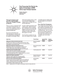
Setup Flowchart
Setup Flowchart
Emulation module
Emulation migration
E5901A
Emulation probe
E5902A
Install emulation
module
(if necessary)
E5900A
Migrating
a module or
a probe?
Module
Probe
Connect power
supply
Connect to LAN
Install software on
logic analysis system
Update emulator
firmware
Target
Interface
Module
Connection
type?
Connect emulator
Analysis
Probe
Connect emulation
module to analysis
probe.
Connect emulator to target
interface module
See solution or analysis
probe manual.
Connect target interface
module to target
Installation done. Begin
making measurements.
E3497F01.VSD
MPC8240 and MPC8260 Emulation
15
Chapter 1: Overview
Emulation Probe
Emulation Probe
Equipment supplied
•
An emulation probe.
•
A 12V power supply for the emulation probe.
•
A power cord.
•
A target interface module (TIM) circuit board.
•
An emulation probe loopback test board (Agilent part number E349666502).
•
A 50-pin ribbon cable (connects the emulation probe to the target
interface module).
•
A 16-pin ribbon cable (connects the target interface module to your target
system).
•
Firmware for the emulation probe on 3.5-inch disks.
•
This User’s Guide.
16
MPC8240 and MPC8260 Emulation
Chapter 1: Overview
Emulation Probe
Equipment Supplied with the Emulation Probe
MPC8240 and MPC8260 Emulation
17
Chapter 1: Overview
Emulation Probe
Minimum equipment required
The following equipment is required to use the emulation probe:
•
A method for connecting the emulator to the target system. You can use an
Agilent Technologies analysis probe or you can design a debug port
connector on the target system. The target system must meet the criteria
on page 63.
•
A host computer, such as a PC or workstation. You can also connect the
emulation probe to an Agilent Technologies 16600A or 16700A logic
analysis system.
•
A LAN (local area network) to connect the emulation probe to the host
computer.
•
A user interface on the host computer, such as a high-level source
debugger or the logic analysis system’s Emulation Control Interface.
To connect the emulation probe to a power
source
The emulation probe does not have an On/Off switch. To turn the
emulation probe on or off, plug or unplug it from the power supply.
The emulation probe is shipped from the factory with a power supply
and cord appropriate for your country. If the cord you received is not
appropriate for your electrical power outlet type, contact your Agilent
Technologies sales and service office.
WARNING:
Use only the supplied Agilent Technologies power supply and cord. Failure to
use the proper power supply could result in electric shock.
CAUTION:
Use only the supplied Agilent Technologies power supply and cord. Failure to
use the proper power supply could result in equipment damage.
18
MPC8240 and MPC8260 Emulation
Chapter 1: Overview
Emulation Probe
1 Connect the power cord to the power supply and to a socket
outlet.
2 Connect the 12V power cord to the back of the emulation probe.
The power light on the target side of the emulation probe will be light.
The emulation probe does not have an On/Off switch.
MPC8240 and MPC8260 Emulation
19
Chapter 1: Overview
Emulation Probe
To power on the system
With all components connected, power on your system as follows:
1 Logic analyzer, if you are using one.
2 Emulation probe.
3 Your target system.
To power off the system
Power off your system as follows:
1 Your target system.
2 Emulation probe.
3 Logic analyzer, if you are using one.
Connection Sequence
Disconnect power from the target system, emulation probe, and logic
analyzer before you make or break connections.
1 Connect the emulation probe to a LAN (page 28).
2 Connect the emulation probe to your target system (page
57).
3 Configure the emulation probe (page 70).
20
MPC8240 and MPC8260 Emulation
Chapter 1: Overview
Emulation Module
Emulation Module
This section lists equipment supplied with the emulation module and
lists the minimum equipment required to use the emulation module.
Equipment supplied
The equipment supplied with your emulation module includes:
•
An Agilent Technologies 16610A emulation module. If you ordered an
emulation module as part of your Agilent Technologies 16600A or 16700A
logic analysis system, it is already installed in the frame.
•
A target interface module (TIM) circuit board.
•
An emulation module loopback test board (Agilent part number E349666502).
•
Firmware for the emulation module and/or updated software for the
Emulation Control Interface on a CD-ROM.
•
A 50-pin ribbon cable for connecting the emulation module to the target
interface module or the Agilent Technologies E2480A analysis probe.
•
A 16-pin ribbon cable for connecting the target interface module to the
target system.
•
Torx T-8, T-10 and T-15 screwdrivers.
•
This User’s Guide.
MPC8240 and MPC8260 Emulation
21
Chapter 1: Overview
Emulation Module
Equipment Supplied with the Emulation Module
Minimum equipment required
The following equipment is required to use the emulation module:
A method for connecting to the target system. The Agilent
Technologies analysis probe provides a debug port connector.
You can also design a debug port connector on the target
system (see “Designing a MPC8240 or MPC8260 Target
System” on page 63).
•
An Agilent Technologies 16600A or 16700A logic analysis system.
•
A user interface, such as a high-level source debugger or the logic analysis
system’s Emulation Control Interface.
22
MPC8240 and MPC8260 Emulation
Chapter 1: Overview
Emulation Migration
Emulation Migration
This section lists equipment supplied with the emulation migration and
lists the minimum equipment required to use the emulation migration.
Equipment supplied
The equipment supplied with your emulation migration includes:
•
A target interface module (TIM) circuit board.
•
Firmware for the emulation module and/or updated software for the
Emulation Control Interface on a CD-ROM.
•
A 16-pin ribbon cable for connecting the target interface module to the
target system.
•
This User's Guide.
MPC8240 and MPC8260 Emulation
23
Chapter 1: Overview
Minimum equipment required
Minimum equipment required
The following equipment is required to use the emulation migration:
•
An emulation module or emulation probe.
•
A 50-pin data cable (supplied with the emulation module or probe).
•
A method for connecting to the target system. An Agilent Technologies
analysis probe provides a debug port connector. You can also design a
debug port connector on the target system.
•
A host computer such as a PC, a workstation, or an Agilent Technologies
16600A or 16700A logic analysis system.
•
A user interface, such as a high-level source debugger or the logic analysis
system's Emulation Control Interface.
24
MPC8240 and MPC8260 Emulation
Chapter 1: Overview
Additional Information Sources
Additional Information Sources
Additional or updated information can be found in the following places:
Newer editions of this manual may be available. Contact your local
Agilent Technologies representative.
If you have an analysis probe, the instructions for connecting the probe
to your target microprocessor are in the analysis probe documentation.
The Solutions User’s Guide for your microprocessor provides
information on using the analysis probe and emulation module
together.
Application notes may be available from your local Agilent
Technologies representative or on the World Wide Web at:
http://www.agilent.com/find/logicanalyzer
If you have an Agilent Technologies 16600A or 16700A logic analysis
system, the online help for the Emulation Control Interface has
additional information on using the emulator.
The measurement examples include valuable tips for making
emulation and analysis measurements. You can find the measurement
examples under the system help in your Agilent Technologies 16600A/
700A logic analysis system.
MPC8240 and MPC8260 Emulation
25
26
MPC8240 and MPC8260 Emulation
2
Connecting the Emulation Probe
to a LAN
27
Chapter 2: Connecting the Emulation Probe to a LAN
You can connect your PC, workstation, or logic analysis
system to the emulation probe via a serial or LAN connection.
Serial connection
A serial connection allows you to complete all of the
performance verification tests and set LAN parameters. Other
use of the serial port is not supported.
LAN connection
A LAN connection will allow you to make your measurements
quickly and easily. A few of the performance verification tests
cannot be run over a LAN.
Recommended connection
Use a LAN connection for routine use, and a serial connection
for LAN configuration and for troubleshooting.
28
MPC8240 and MPC8260 Emulation
Chapter 2: Connecting the Emulation Probe to a LAN
Setting Up a LAN Connection to a PC or
Workstation
The emulation probe has two LAN connectors:
•
A BNC connector that can be directly connected to
an IEEE 802.3 Type 10BASE2 cable (ThinLAN).
When using this connector, the emulation probe
provides the functional equivalent of a Medium Attachment Unit
(MAU) for ThinLAN.
•
An IEEE 802.3 Type 10BASE-T (StarLAN) connector.
Use either the 10BASE2 or the 10BASE-T connector. Do not
use both. The emulation probe will not work with both
connected at the same time.
You must assign an IP address (Internet address) to the
emulation probe before it can operate on the LAN. You can also
set other network parameters such as a gateway address. The
IP address and other network parameters are stored in
nonvolatile memory within the emulation probe.
The emulation probe automatically sets a subnet mask based
on the subnet mask used by other devices on the network.
You can configure LAN parameters in any of the following
ways:
•
Using the built-in terminal interface over a serial connection. This
is the most reliable method.
•
Using BOOTP, which is part of the HP-UX, SunOS, and Solaris
operating systems.
MPC8240 and MPC8260 Emulation
29
Chapter 2: Connecting the Emulation Probe to a LAN
To obtain an IP address
1 Obtain the following information from your local network
administrator or system administrator:
•
An IP address for the emulation probe.
You can also use a "LAN name" for the emulation probe, but you
must configure it using the integer dot notation (such as
127.0.0.1).
•
The gateway address.
The gateway address is an IP address and is entered in integer dot
notation. The default gateway address is 0.0.0.0, which allows all
connections on the local network or subnet. If connections are to
be made to workstations on other networks or subnets, this
address must be set to the address of the gateway machine.
2 Find out whether port numbers 6470 and 6471 are
already in use on your network and if that use
constitutes a conflict.
The host computer interfaces communicate with the
emulation probe through two TCP service ports. The default
base port number is 6470. The second port has the next
higher number (default 6471).
In almost all cases, the default numbers (6470, 6471) can be
used without change. If necessary the default numbers can be
changed if they conflict with some other product on your
network.
To change the port numbers, see page 32. If you have already
set the IP address, you can use a telnet connection instead of a
serial connection to connect to the emulation probe.
30
MPC8240 and MPC8260 Emulation
Chapter 2: Connecting the Emulation Probe to a LAN
3 Write down the link-level address of the emulation probe.
You will need this address if you use BOOTP to set the IP
address.
The link-level address (LLA) is printed on a label above the LAN
connectors on the emulation probe. This address is configured
in each emulation probe shipped from the factory and cannot
be changed.
IP Address of Emulation probe
__________________________
LAN Name of Emulation Probe
__________________________
Gateway Address
__________________________
Link-Level Address of Emulation Probe
__________________________
MPC8240 and MPC8260 Emulation
31
Chapter 2: Connecting the Emulation Probe to a LAN
To configure LAN parameters using the
built-in terminal interface
1 Set configuration switches S1 through S4 to ON, and set
the other switches as appropriate for your serial
interface.
Switch settings are printed on the bottom of the emulation
probe. If you will use a baud rate of 9600 baud, set the
switches like this:
2 Connect an ASCII terminal (or terminal emulator) to the
emulation probe’s RS-232 port with a 9-pin RS-232
cable.
Complete instructions for setting up a serial connection begin
on page 41.
3 Plug in the emulation probe’s power cord. Press the
terminal’s <RETURN> key a couple times. You should see
a prompt such as "p>", "?>", or "R>".
At this point, you are communicating with the emulation
probe’s built-in terminal interface.
32
MPC8240 and MPC8260 Emulation
Chapter 2: Connecting the Emulation Probe to a LAN
4 Display the current LAN configuration values by entering
the lan command:
R>
lan lan is disabled
lan -i 0.0.0.0
lan -g 0.0.0.0
lan -p 6470
Ethernet Address : 08000903212f
The "lan -i" line shows the current IP address (IP address) of
the emulation probe.
The Ethernet address, also known as the link level address, is
preassigned at the factory, and is printed on a label above the
LAN connectors.
5 Enter the following command:
lan -i > [-g >] [-p >]
The lan command parameters are:
-i <internet> The IP address which you obtained from your network
administrator.
-g <gateway> The gateway address. Setting the gateway address allows
access outside your local network or subnet.
-p <port> This changes the base TCP service port number.
The default numbers (6470, 6471) can be changed if they
conflict with some other product on your network. TCP service
port numbers must be greater than 1024. If you change the
base port, the new value must also be entered in the /etc/
services file on the host computer. For example, you could
modify the line:
64700
6470/tcp
The IP address and any other LAN parameters you change are
stored in nonvolatile memory and will take effect the next time
the emulation probe is powered off and back on again.
6 Disconnect the power cord from the emulation probe,
MPC8240 and MPC8260 Emulation
33
Chapter 2: Connecting the Emulation Probe to a LAN
and connect the emulation probe to your network.
This connection can be made by using either the 10BASE-T
connector or the 10BASE2 (BNC) connector on the emulation
probe. Do not use both connectors at the same time.
7 Set the configuration switches to indicate the type of
connection that is to be made.
Switch S1 must be set to OFF, indicating that a LAN
connection is being made.
Switch S5 should be ON if you are connecting to the BNC
connector:
Switch S5 should be OFF if you are connecting to the 10BASET connector:
Set all other switches to ON.
8 Connect the power cord to the emulation probe.
9 Verify your emulation probe is now active and on the
network. See “To verify LAN communications” on
page 39.
Once you have set a valid IP address, you can use the telnet
utility to connect to the emulation probe, and use the lan
command to change LAN parameters.
34
MPC8240 and MPC8260 Emulation
Chapter 2: Connecting the Emulation Probe to a LAN
Example
To assign an IP address of 192.6.94.2 to the emulation
probe, enter the following command:
R>lan -i 192.6.94.2
Now, cycle power on the emulation probe so that the new
address will take effect.
See Also
Page 139, if you have problems verifying LAN communication.
To configure LAN parameters using
BOOTP
Use this method only on a workstation which is running
bootpd, the BOOTP daemon.
1 Make sure that BOOTP is enabled on your host
computer.
If the following commands yield the results shown below, the
BOOTP protocol is enabled:
$ grep bootp /etc/services
bootps
67/udp
bootpc
68/udp
$ grep bootp /etc/inetd.conf
bootps dgram udp wait
root
/etc/bootpd
bootpd
If the commands did not yield the results shown, you must
either add BOOTP support to your workstation or use a
different method to configure the emulation probe LAN
parameters.
MPC8240 and MPC8260 Emulation
35
Chapter 2: Connecting the Emulation Probe to a LAN
2 Add an entry to the host BOOTP database file, /etc/
bootptab.
Example
# Global template for options common to all Agilent
64700
# emulators and Emulation Probes.
# Use a different gateway addresses if necessary.
64700.global:\
:gw=0.0.0.0:\
:vm=auto:\
:hn:\
:bs=auto:\
:ht=ether
# Specific emulator entry specifying hardware
address
# (link-level address) and ip address.
probe.example.com:\
:tc=64700.global:\
:ha=080009090B0E:\
:ip=192.6.29.31
In this example, the "ha=080009090B0E" identifies the
link-level address of the emulation probe. The
"ip=192.6.29.31" specifies the IP address that is assigned
to the emulation probe. The node name is
"probe.example.com".
3 Connect the emulation probe to your network.
This connection can be made by using either LAN connector
on the emulation probe.
4 Set the configuration switches to indicate the type of
connection that is to be made.
Switch S1 must be set to OFF, indicating that a LAN
connection is being made.
Switch S6 must be set to OFF to enable BOOTP mode.
36
MPC8240 and MPC8260 Emulation
Chapter 2: Connecting the Emulation Probe to a LAN
Switch S5 should be set to OFF if you are connecting to the
BNC connector
Switch S5 should be set to ON if you are connecting to the
10BASE-T connector.
Set all other switches to ON.
5 Connect the power cord to the emulation probe.
6 Verify that the power light stays on after 10 seconds.
The IP address will be stored in EEPROM.
7 Set switch S6 back to ON.
Do this so that the emulation probe does not request its IP
address each time power is cycled. The IP address is stored in
EEPROM, so BOOTP does not need to be run again. Leaving
this switch on will result in slower performance, increased
LAN traffic, and even failure to power up (if the BOOTP server
becomes inactive).
8 Verify your emulation probe is now active and on the
network. See "To verify LAN communications" on page
39.
See Also
For additional information about using bootpd, refer to the
bootpd (1M) man page.
MPC8240 and MPC8260 Emulation
37
Chapter 2: Connecting the Emulation Probe to a LAN
To set the 10BASE-T configuration
switches
Set switches S7 and S8 to ON unless one of the following
conditions is true:
• If the LAN cable exceeds the standard length, set switch
S7 to OFF.
The emulation probe has a switch-selectable, twisted-pair
receiver threshold. With switch S7 set to OFF, the twisted-pair
receiver threshold is lowered by 4.5 dB. This should allow you
to use cable lengths of up to about 200 meters. If you use a
long cable, you should consult with your LAN cabling installer
to ensure that:
•
The device at the other end of the cable has long cable
capability, and
•
The cable is high-grade, low-crosstalk cable with crosstalk
attenuation of greater than 27.5 dB.
When switch S7 is set to ON, the LAN port operates at
standard 10BASE-T levels. A maximum of 100 meters of UTP
cable can be used.
• If your network doesn’t support Link Beat integrity
checking or if the emulation probe is connected to a non
10BASE-T network (such as StarLAN) set this switch to
LINK BEAT OFF (0 or OPEN).
In normal mode (switch S8 set to ON), a link integrity pulse is
transmitted every 15 milliseconds in the absence of
transmitted data. It expects to receive a similar pulse from the
remote MAU. This is the standard link integrity test for
10BASE-T networks. If your network doesn’t support the Link
Beat integrity checking or if the emulation probe is used on a
non 10BASE-T network (such as StarLAN) set this switch to
LINK BEAT OFF (OFF).
38
MPC8240 and MPC8260 Emulation
Chapter 2: Connecting the Emulation Probe to a LAN
NOTE:
Setting switch S8 to OFF when Link Beat integrity checking is
required by your network will cause the remote MAU to disable
communications.
To verify LAN communications
1 Verify your emulation probe is now active and on the
network by issuing a telnet to the IP address.
This connection will give you access to the emulation probe’s
built-in terminal interface.
2 To view the LAN parameters, enter the lan command at
the terminal interface prompt.
3 To exit from this telnet session, type <CTRL>D at the
prompt.
The best way to change the emulation probe’s IP address, once
it has already been set, is to telnet to the emulation probe and
use the terminal interface lan command to make the change.
Remember, after making your changes, you must cycle power
or enter a terminal interface init -p command before the
changes take effect. Doing this will break the connection and
end the telnet session.
If You Have
Problems
“If you have problems with the emulator, your first task is to
determine the source of the problem. Problems may originate
in any of the following places:” on page 120.
MPC8240 and MPC8260 Emulation
39
Chapter 2: Connecting the Emulation Probe to a LAN
Example
$ telnet 192.35.12.6
R>lan
lan is enabled
lan -i 192.35.12.6
lan -g 0.0.0.0
lan -p 6470
Ethernet Address : 08000F090B30
40
MPC8240 and MPC8260 Emulation
Chapter 2: Connecting the Emulation Probe to a LAN
Setting Up a Serial Connection
Setting Up a Serial Connection
To set up a serial connection to an emulation probe, you will
need to:
•
Set the serial configuration switches
•
Connect a serial cable between the host computer and the
emulation probe
•
Verify communications
Serial connections on a workstation
If you are using a UNIX workstation as the host computer, you
need to use a serial device file. If a serial device file does not
already exist on your host, you need to create one. Once it
exists, you need to ensure that it has the appropriate
permissions so that you can access it. See the system
documentation for your workstation for help with setting up a
serial device.
Serial connections on a PC
Serial connections are supported on PCs. You must use
hardware handshaking if you will use the serial connection for
anything other than setting LAN parameters.
If you are using a PC as the host computer, you do not need to
set up any special files.
MPC8240 and MPC8260 Emulation
41
Chapter 2: Connecting the Emulation Probe to a LAN
Setting Up a Serial Connection
To set the serial configuration switches
1 Set switch S1 to ON (RS-232).
2 Set switches S2-S4 to ON.
3 Set switch S5 to ON (HW HANDSHAKE ON) if your serial
interface uses the DSR:CTS/RTS lines for flow control.
Set S5 to OFF (HW HANDSHAKE OFF) if your serial
interface uses software flow control (XON/XOFF).
If your serial interface supports hardware handshaking, you
should use it (set switch S5 to ON). Hardware handshaking
will make the serial connection much more reliable.
4 Set switches S6-S8 for the baud rate you will use. These
switch settings are listed on the bottom of the emulation
probe.
The higher baud rates may not work reliably with all hosts and
user interfaces. Make sure the baud rate you choose is
supported by your host and user interface.
Example
To use a baud rate of 9600 baud, set the switches as
follows:
42
MPC8240 and MPC8260 Emulation
Chapter 2: Connecting the Emulation Probe to a LAN
Setting Up a Serial Connection
To connect a serial cable
CAUTION:
Use a grounded, shielded cable. If the cable is not shielded, or if the
cable is not grounded at the serial controller, the emulation probe
may be damaged by electrostatic discharge.
Connect an RS-232C modem cable from the host computer to
the emulation probe. Use a 9-pin cable with one-to-one pin
connections.
If you want to build your own RS-232 cable, follow the pinout
shown in the following figure:
MPC8240 and MPC8260 Emulation
43
Chapter 2: Connecting the Emulation Probe to a LAN
Setting Up a Serial Connection
Serial Cable Pinout
Pin
Number
Signal
Signal Description
1
DCD
Data Carrier Detect (not used)
2
TD
Transmit Data (data coming from Agilent
Technologies emulation probe)
3
RD
Receive Data (data going to
Agilent Technologies emulation probe)
4
DTR
Data Terminal Ready (not used)
5
GND
Signal Ground
6
DSR
Data Set Ready (Output from Agilent
Technologies emulation probe)
7
RTS
Request to Send (Input to Agilent
Technologies emulation probe)
8
CTS
Clear to Send (connected to pin 6)
9
RING
Ring Indicator (not used)
44
MPC8240 and MPC8260 Emulation
Chapter 2: Connecting the Emulation Probe to a LAN
Setting Up a Serial Connection
To verify serial communications
1 Start a terminal emulator program on the host computer.
If you are using a PC, the Terminal application in Microsoft
Windows will work fine.
If you are using a UNIX workstation, you can use a terminal
emulator such as cu or kermit.
2 Plug the power cord into the emulation probe.
When the emulation probe powers up, it sends a message
(similar to the one that follows) to the serial port and then
displays a prompt:
Copyright (c) Agilent Technologies 1987
All Rights Reserved. Reproduction, adaptation, or translation without
prior written permission is prohibited, except as allowed under
copyright laws.
E3499B Series Emulation System
Version:
A.07.56 28Sep98
Location: Generics
E3453A Motorola MPC8200 Embedded PowerPC Emulator
Version:
A.01.00 18Feb99
R>
The version numbers may be different for your emulation
probe.
3 Press the Return or Enter key a few times.
You should see a prompt such as "p>", "R>", or "?>".
For information about the commands you can use, enter ? or
help at the prompt.
See Also
“If you have problems with the emulator, your first task is to
determine the source of the problem. Problems may originate
in any of the following places:” on page 120.
MPC8240 and MPC8260 Emulation
45
Chapter 2: Connecting the Emulation Probe to a LAN
Setting Up a Serial Connection
46
MPC8240 and MPC8260 Emulation
3
Installing the Emulation Module
45
Chapter 3: Installing the Emulation Module
This chapter shows you how to install an emulation module in your
Agilent Technologies 16600A/700A-series logic analysis system.
If your emulation module is already installed in your logic analysis
system frame, you may skip this chapter.
CAUTION:
These instructions are for trained service personnel. To avoid dangerous
electric shock, do not perform any service unless qualified to do so. Do not
attempt internal service or adjustment unless another person, capable of
rendering first aid and resuscitation, is present.
Electrostatic discharge can damage electronic components. Use grounded
wrist straps and mats when you handle modules.
46
MPC8240 and MPC8260 Emulation
Chapter 3: Installing the Emulation Module
To install the emulation module in a 16700Aseries logic analysis system or a 16701A
expansion frame
You will need T-10 and T-15 Torx screw drivers.
1 Turn off the logic analysis system and REMOVE THE POWER
CORD.
Remove any other cables (including mouse or video monitor cables).
2 Turn the logic analysis system frame upside-down.
3 Remove the bottom cover.
4 Remove the slot cover.
You may use either slot.
MPC8240 and MPC8260 Emulation
47
Chapter 3: Installing the Emulation Module
5 Install the emulation module.
6 Connect the cable and re-install the screws.
You may connect the cable to either of the two connectors. If you have
two emulation modules, note that many debuggers will work only with
the "first" module: the one toward the top of the frame ("Slot 1"),
plugged into the connector nearest the back of the frame.
7 Reinstall the bottom cover, then turn the frame right-side-up.
8 Plug in the power cord, reconnect the other cables, and turn on
the logic analysis system.
The new emulation module will be shown in the system window.
48
MPC8240 and MPC8260 Emulation
Chapter 3: Installing the Emulation Module
To install the emulation module in a 16600Aseries logic analysis system
You will need T-8, T-10, and T-15 Torx screw drivers (supplied with the
modules).
1 Turn off the logic analysis system and REMOVE THE POWER
CORD.
Remove any other cables (such as probes, mouse, or video monitor).
2 Slide the cover back.
3 Remove the slot cover.
MPC8240 and MPC8260 Emulation
49
Chapter 3: Installing the Emulation Module
4 Install the emulation module.
5 Connect the cable and re-install the screws.
6 Reinstall the cover.
Tighten the screws snugly ( 2 N-m or 18 inch-pounds).
7 Plug in the power cord, reconnect the other cables, and turn on
the logic analysis system.
The new emulation module will be shown in the system window.
50
MPC8240 and MPC8260 Emulation
4
Installing Software on a 16600A/700A
51
Chapter 4: Installing Software on a 16600A/700A
This chapter explains how to install the software you will need for your
analysis probe or emulation solution.
Installing and loading
Installing the software will copy the files to the hard disk of your logic
analysis system. Later, you will need to load some of the files into the
appropriate hardware module.
Logic analysis system or logic analyzer frame
CD-ROM or
flexible disk
Install
Load
Hard Disk
Logic analyzer
or emulation
module
What needs to be installed
Agilent Technologies 16600A/700A-series logic analysis
systems
If you ordered an emulation solution with your logic analysis system,
the software was installed at the factory.
The following files are installed when you install a processor support
package from the CD-ROM:
•
Logic analysis system configuration files
•
Inverse assembler (automatically loaded with the configuration files)
•
Personality files for the Setup Assistant
•
Emulation module firmware (for emulation solutions)
•
Emulation Control Interface (for emulation solutions)
The Agilent Technologies B4620B Source Correlation Tool Set is
installed with the logic analysis system’s operating system.
52
MPC8240 and MPC8260 Emulation
Chapter 4: Installing Software on a 16600A/700A
To install the software from CD-ROM (16600A/
700A)
Installing a processor support package from a CD-ROM will take just a
few minutes. If the processor support package requires an update to
the Agilent Technologies 16600A/700A logic analysis system operating
system, installation may take approximately 15 minutes.
If the CD-ROM drive is not connected, see the instructions printed on
the CD-ROM package.
1 Turn on the CD-ROM drive first and then turn on the logic
analysis system.
2 Insert the CD-ROM in the drive.
3 Click the System Admin icon.
4 Click Install... .
Change the media type to “CD-ROM” if necessary.
5 Click Apply.
6 From the list of types of packages, select “PROC-SUPPORT.”
A list of the available processor support packages will be displayed.
7 Click on the “MPC82XX” package.
If you are unsure if this is the correct package, click Details for
information on what the package contains.
8 Click Install... .
The dialog box will display “Progress: completed successfully” when
the installation is complete.
MPC8240 and MPC8260 Emulation
53
Chapter 4: Installing Software on a 16600A/700A
9 Click Close.
The configuration files are stored in /logic/configs/hp/
processor. The inverse assemblers are stored in /logic/ia.
See Also
The instructions printed on the CD-ROM package for a summary of the
installation instructions.
The online help for more information on installing, licensing, and
removing software.
To list software packages which are installed
(16600A/700A)
In the System Administration Tools window, click List... .
54
MPC8240 and MPC8260 Emulation
Chapter 4: Installing Software on a 16600A/700A
MPC8240 and MPC8260 Emulation
55
56
MPC8240 and MPC8260 Emulation
5
Connecting and Configuring the
Emulator
57
Chapter 5: Connecting and Configuring the Emulator
This chapter shows you how to connect the emulator to the target
system and how to configure the emulator and target.
Here is a summary of the steps for connecting and configuring the
emulator:
1 Make sure the target system is designed to work properly with
the emulator. (page 63)
2 Install the emulation module in your logic analysis system, if
necessary. (page 45)
3 Connect the emulator to your target system using the 16-pin
cable and the TIM or an analysis probe. (page 66)
4 Update the firmware of the emulator, if necessary. (page
107)
5 Verify communication between the emulator and the
target. (page 69)
6 Configure the emulator. (page 70)
7 Test the connection between the emulator and the target.
(page 81)
8 Connect a debugger to the emulator, if applicable. (page
83.)
See Also
Chapter 6, “Using the Emulator with a Debugger,” beginning
on page 83 for information on configuration with a debugger,
and on configuring LAN port numbers.
58
MPC8240 and MPC8260 Emulation
Chapter 5: Connecting and Configuring the Emulator
Using the Emulation Control Interface
Using the Emulation Control Interface
The Emulation Control Interface in your Agilent Technologies 16600A/
700A-series logic analysis system allows you to control an emulator (an
emulation module or an emulation probe).
As you set up the emulator, you will use the Emulation Control
Interface to:
•
Update firmware (which reloads or changes the processor-specific
personality of the emulator).
•
Change the LAN port assignment (rarely necessary).
•
Run performance verification tests on the emulator.
The Emulation Control Interface allows you to:
•
Run, break, reset, and step the target processor.
•
Set and clear breakpoints.
•
Read and write registers.
•
Read and write memory.
•
Read and write I/O memory.
•
View memory in mnemonic form.
•
Read and write the emulator configuration.
•
Download programs (in Motorola S-Record or Intel Hex format) to the
target system RAM or ROM.
•
View emulator status and errors.
•
Write and play back emulator command script files.
If you have an emulation probe, this interface also allows you to
configure the LAN address of the emulation probe.
Using the logic analysis system’s intermodule bus does not require the
Emulation Control Interface to be running. If the emulation module
icon is in the Intermodule window, then it will be able to send and
receive signals. Therefore if you are using a debugger, you can use an
MPC8240 and MPC8260 Emulation
59
Chapter 5: Connecting and Configuring the Emulator
Using the Emulation Control Interface
analyzer to cause a break.
Using a debugger with the Emulation Control Interface is not
recommended because:
See Also
•
The interfaces can get out of synchronization when commands are issued
from both interfaces. This causes windows to be out-of-date and can cause
confusion.
•
Most debuggers cannot tolerate another interface issuing commands and
may not start properly if another interface is running.
All of the Emulation Control Interface windows provide online help
with a Help button or a Help➞On this window menu selection. Refer
to the online help for complete details about how to use a particular
window.
To start the Emulation Control Interface from
the main System window (emulation module)
1 In the System window, click the emulation module icon.
2 Select Start Session....
60
MPC8240 and MPC8260 Emulation
Chapter 5: Connecting and Configuring the Emulator
Using the Emulation Control Interface
To start the Emulation Control Interface from
the Workspace window (emulation module)
1 Open the Workspace window.
2 Drag the Emulator icon onto the workspace.
3 Right-click on the Emulator icon, then select Start Session....
MPC8240 and MPC8260 Emulation
61
Chapter 5: Connecting and Configuring the Emulator
Using the Emulation Control Interface
To start the Emulation Control Interface from
the Workspace window for an emulation probe
If you have a stand-alone emulation probe connected to the logic
analysis system via LAN, use the Emulation Probe icon instead of the
Emulator icon.
1 Open the Workspace window.
2 Drag the Emulation Probe icon onto the workspace.
3 Right-click on the Emulation Probe icon, then select Start
Session....
4 In the Session window, enter the IP address or LAN name of the
emulation probe, then click Start Session.
62
MPC8240 and MPC8260 Emulation
Chapter 5: Connecting and Configuring the Emulator
Designing a MPC8240 or MPC8260 Target System
Designing a MPC8240 or MPC8260 Target
System
Debug Port Connection
A 2x8 0.1 inch center BERG-style connector is required to connect the
emulation probe to the MPC8260 PowerQUICC II JTAG interface or the
MPC8240 JTAG interface. The header should be placed as close to the
microprocessor as possible to ensure signal integrity. TDO, TDI, TCK,
TMS, and TRST should have signal traces less than three inches
between the JTAG connector and the microprocessor. If these signals
are connected to other nodes, it is required that they connect in a daisy
chain between the JTAG debug connector and the MPC8260
PowerQUICC II or the MPC8240. These signals are sensitive to crosstalk and cannot be routed next to active signals such as clocks.
The TDI, TCK, TMS, and TRST signals must not be actively driven by
the target system when the debug port is being used.
The Agilent Technologies emulation probe/module adds about 40pF to
all target system signals routed to the debug connector. This added
capacitance may reduce the rise time of the HRESET and SRESET
signals beyond the processor specifications. If so, the target may need
to increase the pull-up current on these signal lines.
When the 'rst' command on the probe/module is used, HRESET is held
low for approximately 300ms.
MPC8240 and MPC8260 Emulation
63
Chapter 5: Connecting and Configuring the Emulator
Designing a MPC8240 or MPC8260 Target System
Reset Signals for the MPC8240
The SRESET, HRESET signals from the JTAG connector may be
logically ORed with their respective signals on the target system. The
MPC8240 has two hard resets, HRST_CPU and HRST_CTRL. HRESET
from the debug connector must be routed to the HRST_CPU reset logic
and optionally routed to the HRST_CTRL reset logic depending on
system requirements.
The emulation probe/module drives SRESET and HRESET with opendrain drivers using 2.7 Kohm pullups to VDD. The target system
designer may take advantage of these open-drain drivers by wireORing SRESET and/or HRESET to open-drain drivers on the target
system. It is not necessary to use a wire-OR configuration, but reset
status messages can only be generated by the probe/module when
using the wire-ORed configuration.
The TRST signal from the JTAG connector must be logically ORed with
TRST on the target system. TRST is actively driven by the probe/
module and cannot be wire-ORed.
Reset Signals for the MPC8260
SRESET and HRESET from the debug connector must be ORed with
the respective SRESET and HRESET signals on the target system.
They they can be logically ORed or wire-ORed on the target system.
The emulation probe/module drives SRESET and HRESET with opendrain drivers using 2.7 Kohm pullups to VDD.
It is not necessary to use a wire-OR configuration, but reset status
messages can only be generated by the probe/module when using the
wire-ORed configuration.
The TRST signal from the JTAG connector must be logically ORed with
TRST on the target system. TRST is actively driven by the probe/
module and cannot be wire-ORed.
64
MPC8240 and MPC8260 Emulation
Chapter 5: Connecting and Configuring the Emulator
Designing a MPC8240 or MPC8260 Target System
JTAG Connector Pinout and Electrical Information
!"#!
$
%
&
'
((
)((
(*
)
+
,
To test the emulator
If this is the first time that you have used the emulator, you should run
the built-in performance verification test before you connect to a target
system. Refer to page 141 for information on performance
verification.
MPC8240 and MPC8260 Emulation
65
Chapter 5: Connecting and Configuring the Emulator
Connecting the Emulator to the Target System
Connecting the Emulator to the Target System
Choose one of the following methods for connecting the emulator to a
target system.
•
Directly through a debug port connector on the target board.
•
Through an Agilent Technologies analysis probe, which provides a direct
connection to the debug port pins.
66
MPC8240 and MPC8260 Emulation
Chapter 5: Connecting and Configuring the Emulator
Connecting the Emulator to the Target System
After you have connected the emulator to your target system, you may
need to update the firmware in the emulator.
See Also
For information on designing a debug port on your target
board, see page 63.
For a list of the parts supplied with the emulator, see page 21.
To connect to a target system using a 16-pin
debug port
The emulator can be connected to a target system through a 16-pin
debug port (JTAG connector).
The emulator should be connected to the target system using the 16conductor cable assembly provided.
In order to connect the emulator to the microcontroller, a 16-pin male
2x8 header connector must be available on the target system.
1 Remove power from the target system and the emulator.
2 Plug one end of the 50-pin cable into the emulator.
3 Plug the other end of the 50-pin cable into the target interface
module.
4 Plug one end of the 16-pin cable into the target interface module.
MPC8240 and MPC8260 Emulation
67
Chapter 5: Connecting and Configuring the Emulator
Connecting the Emulator to the Target System
5 Plug the other end of the 16-pin cable into the target system.
Orient the red wire away from pin 1 of the connector and towards the
key pin. See the drawing on page 65.
CAUTION:
Be careful to orient the connector as described above. If the connector is
rotated, your target system or the emulator may be damaged.
6 Turn on the power to the logic analysis system, then turn on the
power to the target system.
To connect to a target system using an analysis
probe
1 Remove power from the target system.
2 Plug one end of the 16-pin cable into the emulator. The
connectors are keyed.
3 Plug the other end of the 16-pin cable into the connector on the
analysis probe.
68
MPC8240 and MPC8260 Emulation
Chapter 5: Connecting and Configuring the Emulator
Connecting the Emulator to the Target System
To verify communication between the
emulator and target system
1 Turn on the target system.
2 Start the Emulation Control Interface.
If the electrical connections are correct, and if the emulator firmware
and analysis probe or TIM match your target processor, the Run
Control window should be displayed:
MPC8240 and MPC8260 Emulation
69
Chapter 5: Connecting and Configuring the Emulator
Configuring the Emulator
Configuring the Emulator
The emulator has several user-configurable options. These options may
be customized for specific target systems and saved in configuration
files for future use.
The easiest way to configure the emulator is through the Emulation
Control Interface in an Agilent Technologies 16600A or 16700A
logic analysis system.
If you use the Emulation Control Interface, please refer to the online
help in the Configuration window for information on each of the
configuration options.
Other ways to configure the emulator are by using:
•
•
70
the emulator’s built-in terminal interface
your debugger, if it provides an “emulator configuration” window which
can be used with this Agilent Technologies emulator
MPC8240 and MPC8260 Emulation
Chapter 5: Connecting and Configuring the Emulator
Configuring the Emulator
To configure using the Emulation Control
Interface
The easiest way to configure the emulator is to use the Emulation
Control Interface.
1 Start an Emulation Control Interface session.
In the system window, click the Emulation Control Interface icon, and
then select Start Session....
2 Open a Configuration window.
Select Configuration... from the Emulation Control Interface icon or
from the Navigate menu in any Emulation Control Interface window.
3 Set the configuration options, as needed.
Configuration changes will take effect when you close the configuration
window or when you move the mouse pointer outside the window.
4 Save the configuration settings.
To save the configuration settings, open the File Manager window and
click Save....
See Also
Help➞Help on this window in the Configuration window for
MPC8240 and MPC8260 Emulation
71
Chapter 5: Connecting and Configuring the Emulator
Configuring the Emulator
information on each of the configuration options.
Help in the Emulation Control Interface menu for help on starting an
Emulation Control session.
To configure using the built-in commands
If you are unable to configure the emulator with the Emulation Control
Interface or a debugger interface, you can configure the emulator using
the built-in “terminal interface” commands.
1 Connect a telnet session to the emulator over the LAN.
For example, on a UNIX system, for an emulation module in Slot 1
enter:
telnet LAN_address 6472
2 Enter cf to see the current configuration settings.
3 Use the cf command to change the configuration settings.
See Also
Enter help cf for help on the configuration commands.
For information on connecting using telnet, and for information on
other built-in commands, see page 125.
72
MPC8240 and MPC8260 Emulation
Chapter 5: Connecting and Configuring the Emulator
Configuring the Emulator
Example
To see a complete list of configuration items, type help cf. This
command displays:
M>help cf
cf - display or set emulation configuration
cf
- display current settings for all config items
cf <item>
- display current setting for specified <item>
cf <item>=<value> - set new <value> for specified <item>
cf <item> <item>=<value> <item> - set and display can be combined
help cf <item>
- display long help for specified <item>
--- VALID CONFIGURATION <item> NAMES --proc
- Set type of processor
reset
- Run or stop after reset
vector
- Reset vector address
rrt
- Set restriction to real time runs
breakin - BNC break in control
trigout - Trigger out control
speed
- Set JTAG Clock Divisor
M>
To configure using a debugger
Because the Agilent Technologies emulator can be used with several
third-party debuggers, specific details for sending the configuration
commands from the debugger to the emulator cannot be given here.
However, all debuggers should provide a way of directly entering
terminal mode commands to the emulator. Ideally, you would create a
file that contains the modified configuration entries to be sent to the
emulator at the beginning of each debugger session.
See Also
Information about specific debuggers in Chapter 6, “Using the
Emulator with a Debugger,” beginning on page 83.
Your debugger manual.
MPC8240 and MPC8260 Emulation
73
Chapter 5: Connecting and Configuring the Emulator
Configuring the Emulator
To configure the processor type
Processor type configuration
Value
Emulation module configured for
Built-in command
MPC8260
Motorola MPC8260 (ver. 1.0)
cf proc=MPC8260
MPC8240
Motorola MPC8240 (ver. 1.0)
cf proc=MPC8240
The cfsave -s command will store the processor type configuration in
the emulation module’s flash memory. The cfsave -r command will
restore this configuration.
To configure reset operation
The reset configuration item controls what kind of reset is performed
and what state the processor will be in after the reset.
Reset configuration
Value
Effect of a reset from the emulation module Built-in command
run
Issuing the rst command will hard reset the cf reset=run
processor, reset the JTAG interface, and
allow the processor to run. (Default)
stop
Issuing the rst command will hard reset the cf reset=stop
processor, reset the JTAG interface, and
cause the processor to stop at the reset
exception vector 0xfff00100 or 0x00000100.
The address used is determined by the
config item 'vector'.
74
MPC8240 and MPC8260 Emulation
Chapter 5: Connecting and Configuring the Emulator
Configuring the Emulator
To configure reset vector address
The reset vector address configuration item specifies which reset
vector the target hardware is using. This value does not set the reset
vector. This is done by the hardware.
Vector address configuration
Value
Emulation module configured for
Built-in command
fff00100
Default
cf vector=fff00100
00000100
cf vector=00000100
To configure restriction to real-time runs
This option enables or disables restriction to real-time runs
implemented for all commands other than "rst", "b", "s" and "r".
Real-time runs configuration
Value
Emulation module configured for
Built-in command
no
cf rrt=no
If the processor is running user code, a
request for a register or memory display
will put the processor in monitor mode,
read the requested register(s), then restore
the processor to running user code.
(Default)
yes
If the processor is running user code, a
cf rrt=yes
request for a memory or register display
will return: !ERROR 647! Restricted to Real
Time
If your debugger allows displaying or modifying memory or registers
while the processor is running, you must set rrt=no in order to use that
feature.
MPC8240 and MPC8260 Emulation
75
Chapter 5: Connecting and Configuring the Emulator
Configuring the Emulator
To configure the BNC Break In control
BNC Break In control configuration
Value
Emulation module configured for
Built-in command
rising
Causes the 'break in' input to halt the
processor on a rising edge (Default).
cf breakin=rising
falling
Breaks the processor on a falling edge.
off
cf breakin=falling
cf breakin=off
To configure the Trigger Out BNC (Emulation
Probe Only)
With an emulation module, this configuration item is always set to the
default setting and cannot be changed with a cf command. The
Intermodule window of the logic analysis system must be used instead.
Trigger out configuration
Value
The Trigger Out BNC will
Built-in command
fixhigh
Always be high
cf trigout=fixhigh
fixlow
Always be low
cf trigout=fixlow
monhigh
Go high when the processor is running in
background (Default)
cf trigout=monhigh
monlow
Go low when the processor is running in
background
cf trigout=monlow
76
MPC8240 and MPC8260 Emulation
Chapter 5: Connecting and Configuring the Emulator
Configuring the Emulator
To configure the JTAG clock speed
(communication speed)
The Agilent Technologies emulation module needs to be configured to
communicate at a rate which is compatible with your target processor.
The JTAG clock speed is independent of processor clock speed.
The base JTAG clock frequency is 10MHz. This configuration item
selects the division factor for the clock.
Processor clock speed configuration
Value
Processor clock (CLKIN) is at least
Built-in command
1
10 MHz (default)
cf speed=1
2
5 MHz
cf speed=2
3
2.5 MHz
cf speed=3
4
1.25 MHz
cf speed=4
5
625 KHz
cf speed=5
MPC8240 and MPC8260 Emulation
77
Chapter 5: Connecting and Configuring the Emulator
Configuring the Emulator
Configuration registers (MPC8260 Only)
Configuration registers are emulation probe copies of particular
registers and are used as described below. These registers may be
read/written by using the 'reg' command.
cf_immr
The cf_immr register is used by the probe to determine the location of
the internal memory map and to read/write the IMMR memory mapped
register.
Do not modify the IMMR by using a direct memory access. This will
cause the cf_immr register to be out of sync with the real IMMR
causing the emulation probe to lose track of the IMMR location.
Reading the cf_immr checks to see if the processor memory map has
moved. If the cf_immr is does not reflect the actual IMMR, then an
error is generated stating that the memory map has moved and its
location is unknown.
To recover from the condition when the cf_immr does not match the
actual IMMR, either update the cf_immr with the correct value (reg
cf_immr=xxxxxxxx) or set the cf_immr to the reset value and issue the
probe reset command (rst).
A write to the cf_immr causes a write to the real IMMR if its location is
known. Writing to the cf_immr changes the cf_immr contents and also
changes the memory mapped IMMR contents. Once again an error is
generated if the memory map has moved and cannot be located.
78
MPC8240 and MPC8260 Emulation
Chapter 5: Connecting and Configuring the Emulator
Configuring the Emulator
Before resetting the target or issuing the probe reset command (rst),
the cf_immr register must be set to the reset value as defined by the
reset configuration word. If after reset user code changes the IMMR
value, then the cf_immr copy must also be updated.
The default value for cf_immr is 0x0f000000 when the emulation probe
is powered on or when the 'init -c' command is issued.
cf_sypcr
The cf_sypcr register is used to disable the watchdog timer after a
probe reset command (rst) is issued. Since the SYPCR is a write once
register, direct writes to the SYPCR register have no effect while using
the probe.
If a value other than the default is desired, then the cf_sypcr register
must be set (reg cf_sypcr=xxxxxxxx) and the SYPCR will be updated
on the next probe reset command (rst). The probe can only disable
the watchdog timer if the 'rst' command is used. Pressing the target
reset button will not disable the timer. The default value is 0xffffffc3.
Cache support
This version of the firmware does not support the cpu running with
cache on. Targets must not enable cache.
Break
If the following error occurs, the processor is in an unstable state and
should be reset via a hard reset or a power-on reset. The 'rst' command
may not be able to bring the processor into a known state.
!ERROR
clocks
145! Unable to soft stop - freezing the processor
MPC8240 and MPC8260 Emulation
79
Chapter 5: Connecting and Configuring the Emulator
Configuring the Emulator
Software Breakpoints
The number of software breakpoints is unlimited but they cannot be
used with ROM or FLASH memory. Software breakpoints cannot be
used to debug exceptions. Do not modify the IABR register while
software breakpoints are enabled.
It is recommended that only -t (temporary) or -p (permanent)
breakpoints be used by a debugger. If neither option is given, the
breakpoint acts much like a temporary breakpoint except that when
the breakpoint is hit, it is disabled but remains in the breakpoint list. A
temporary breakpoint is removed from the breakpoint list when hit.
NOTE:
For software breakpoints, the break conditions set are dependent on the value
of the MSR(IP) bit value. When software breakpoints are enabled, the value of
this bit determines the break condition. If user code or debuggers change this
value after software breakpoints have been enabled, software breakpoints will
not work. The work around for this is to set a hardware breakpoint to an
instruction after the code that changes the MSR(IP), then after hitting the
hardware breakpoint, disable hardware breakpoints and enable software
breakpoints.
Hardware Breakpoints
One hardware breakpoint is available. Since using software
breakpoints requires the use of the hardware breakpoint, both types of
breakpoints cannot be used at the same time. Enable hardware
breakponts using 'bc -e hwbp'. Set a hardware breakpoint using 'bp -h
<-p | -t> <address>. Use either the -p or -t option when setting the
hardware breakpoints.
80
MPC8240 and MPC8260 Emulation
Chapter 5: Connecting and Configuring the Emulator
Testing the emulator and target system
Testing the emulator and target system
After you have connected and configured the emulator, you should
perform some simple tests to verify that everything is working.
See Also
Chapter 10, “Troubleshooting the Emulator,” beginning on
page 120, for information on testing the emulator hardware.
To test memory accesses
1 Start the Emulation Control Interface and configure the emulator
and target memory system.
2 Open the Memory window.
3 Write individual locations or fill blocks of memory with patterns
of your choosing.
The access size is the size of memory access that will be used to write
or read the memory values.
4 Use the Memory I/O window to stimulate I/O locations by reading
and writing individual memory locations.
MPC8240 and MPC8260 Emulation
81
Chapter 5: Connecting and Configuring the Emulator
Testing the emulator and target system
To test with a running program
To more fully test your target, you can load simple programs and
execute them.
1 Compile or assemble a small program and store it in a Motorola SRecord or Intel Hex file.
2 Use the Load Executable window to download the program into
RAM or flash memory.
3 Use the Breakpoints window to set breakpoints. Use the
Registers window to initialize register values.
The new register or breakpoint values are sent to the processor when
you press the Enter key or when you move the cursor out of the
selected register field.
4 In the Run Control window, click Run.
5 Use the Memory Mnemonic window to view the program and use
the Memory window to view any output which has been written
to memory.
82
MPC8240 and MPC8260 Emulation
6
Using the Emulator with a Debugger
83
Chapter 6: Using the Emulator with a Debugger
Several prominent companies design and sell state-of-the-art source
debuggers which work with the Agilent Technologies emulation module
and emulation probe.
Benefits of using a debugger
The debugger will enable you to control the execution of your
processor from the familiar environment of your debugger. Using a
debugger lets you step through your code at the source-code level.
With a debugger connection, you can set breakpoints, single-step
through source code, examine variables, and modify source code
variables from the debugger interface. The debugger can also be used
to download executable code to your target system.
Using a debugger to connect to the emulator allows the entire design
team to have a consistent interface from software development to
hardware/software integration.
Debugger interfaces must be ordered directly from the debugger
vendor.
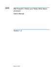
Compatibility with other logic analysis system tools
You can use your logic analysis system to collect and analyze trace data
while you use your debugger. If you are using an X windows
workstation or a PC with an X terminal emulator, you can display the
logic analyzer windows right next to your debugger.
84
MPC8240 and MPC8260 Emulation
Chapter 6: Using the Emulator with a Debugger
Here is an example of what the display on your PC or workstation
might look like:
MPC8240 and MPC8260 Emulation
85
Chapter 6: Using the Emulator with a Debugger
Minimum requirements
To use a debugger with the emulator, you will need:
•
A debugger which is compatible with the emulator
•
A LAN connection to the PC or workstation that is running the debugger
•
X windows or an X terminal emulator, such as Reflection X on a PC. This is
required only if you wish to have the logic analysis system user interface
displayed on your PC or workstation screen, along with the debugger.
Is your debugger compatible with the emulator?
Ask your debugger vendor whether the debugger can be used with an
Agilent Technologies emulation module or Agilent Technologies
emulation probe (also known as a "processor probe" or "software
probe").
LAN connection
You will use a LAN connection to allow the debugger to communicate
with the emulator.
Compatibility with the Emulation Control Interface
Do not use the logic analysis system's Emulation Control Interface and
your debugger at the same time.
86
MPC8240 and MPC8260 Emulation
Chapter 6: Using the Emulator with a Debugger
Setting Up Debugger Software
Setting Up Debugger Software
The instructions in this manual assume that your PC or workstation is
already connected to the LAN, and that you have already installed the
debugger software according to the debugger vendor's documentation.
To use your debugger with the emulator, follow these general steps:
•
Connect the emulator to your target system (see page 66).
•
Connect the emulator or logic analysis system to the LAN (page
88).
•
Export the logic analysis system's display to your PC or workstation
(page 91).
•
Configure the emulator (page 70).
•
Begin using your debugger.
If you use the Emulation Control Interface to configure the emulator,
remember to end the Emulation Control Interface session before you
start the debugger.
CAUTION:
Do not use the Emulation Control Interface at the same time as a debugger.
The Emulation Control Interface and debuggers do not keep track of
commands issued by other tools. If you use both at the same time, the tools
may display incorrect information about the state of the processor, possibly
resulting in lost data.
See Also
Refer to the documentation for your debugger for more information on
connecting the debugger to the emulator.
MPC8240 and MPC8260 Emulation
87
Chapter 6: Using the Emulator with a Debugger
Setting Up Debugger Software
To connect the logic analysis system to the
LAN
Information on setting up a LAN connection is provided in the online
help or installation manual for your logic analysis system.
Your debugger will require some information about the LAN connection
before it can connect to the emulator. This information may include:
•
IP address (Internet address) or LAN name of the logic analysis system.
•
Gateway address of the logic analysis system.
•
Port number of the emulator.
Port numbers for emulators
Port number
Debugger connections
6470
6474
6478
6482
Telnet connections
6472
6476
6480
6484
Use for
Slot 1 (First emulator in an Agilent Technologies
16600A/700A-series logic analysis system)
Slot 2 (Second emulator in an Agilent Technologies
16700A-series system)
Slot 3 (Third emulator in an expansion frame)
Slot 4 (Fourth emulator in an expansion frame)
Slot 1 (First emulator)
Slot 2 (Second emulator)
Slot 3 (Third emulator)
Slot 4 (Fourth emulator)
Write the information here for future reference:
IP Address of Logic Analysis System
___________________________
LAN Name of Logic Analysis System
___________________________
Gateway Address
___________________________
Port Number of Emulator
___________________________
88
MPC8240 and MPC8260 Emulation
Chapter 6: Using the Emulator with a Debugger
Setting Up Debugger Software
To change the port number of an emulation
module
Some debuggers do not provide a means to specify a port number. In
that case, the debugger will always connect to port 6470 (the first
emulator). If you need to connect to another module, or if the port
number of the first module has been changed, you must change the
port number to be 6470.
To view or change the port number:
1 Click on the emulation module icon in the system window of the
logic analysis system, then select Update Firmware.
2 Select Modify Lan Port...
3 If necessary, enter the new port number in the Lan Port
Address field.
The new port number must be greater than 1024 and must not already
be assigned to another emulator.
MPC8240 and MPC8260 Emulation
89
Chapter 6: Using the Emulator with a Debugger
Setting Up Debugger Software
To verify communication with the emulator
1 Telnet to the IP address.
For example, on a UNIX system, enter “telnet <IP_address> 6472”.
This connection will give you access to the emulator’s built-in terminal
interface. You should see a prompt, such as “M>”.
2 At the prompt, type:
ver
You should then see information about the emulator and firmware
version.
3 To exit from this telnet session, type <CTRL>D at the prompt.
See Also
The online help or manual for your logic analysis system, for
information on physically connecting the system to the LAN and
configuring LAN parameters.
90
MPC8240 and MPC8260 Emulation
Chapter 6: Using the Emulator with a Debugger
Setting Up Debugger Software
To export the logic analysis system’s display to
a workstation
By exporting the logic analyzer’s display, you can see and use the logic
analysis system’s windows on the screen of your workstation. To do
this, you must have telnet software and X window installed on your
computer.
1 On the workstation, add the host name of the logic analysis
system to the list of systems allowed to make connections:
xhost +<IP_address>
2 Use telnet to connect to the logic analysis system.
telnet <IP_address>
3 Log in as “logic”.
The logic analysis system will open a Session Manager window on your
display.
4 In the Session Manager, click Start Session on This Display.
Example
On a UNIX workstation, you could use the following commands to
export the display of a logic analysis system named “mylogic”:
$ xhost +mylogic
$ telnet mylogic
Trying...
Connected to mylogic.mycompany.com.
Escape character is ‘^]’.
Local flow control on
Telnet TERMINAL-SPEED option ON
Agilent Technologies Logic Analysis System
Please Log in as: logic [displayname:0]
login: logic
Connection closed by foreign host.
MPC8240 and MPC8260 Emulation
91
Chapter 6: Using the Emulator with a Debugger
Setting Up Debugger Software
To export the logic analysis system’s display to
a PC
By exporting the logic analyzer’s display, you can see and use the logic
analysis system’s windows on the screen of your PC. To do this, you
must have telnet software and an X terminal emulator installed on your
computer. The following instructions use the Reflection X emulator
from WRQ, running on Windows 95, as an example.
1 On the PC, start the X terminal emulator software.
To start Reflection X, click the Reflection X Client Startup icon.
2 Start a telnet connection to the logic analysis system.
Log in as “logic”.
For Reflection X, enter the following values in the Reflection X Client
Startup dialog:
a In the Host field, enter the LAN name or IP address of the
logic analysis system.
b In the User Name field, enter “logic”.
c Leave the Password field blank.
d Leave the Command field blank.
e Click Run to start the connection.
The logic analysis system will open a Session Manager window on your
display.
3 In the Session Manager window, click Start Session on This
Display.
92
MPC8240 and MPC8260 Emulation
7
Using the Analysis Probe and
Emulation Module Together
93
Chapter 7: Using the Analysis Probe and Emulation Module Together
This chapter describes how to use an analysis probe, an emulation
module, and other features of your Agilent Technologies 16600A or
16700A logic analysis system to gain insight into your target system.
What are some of the tools I can use?
You can use a combination of all of the following tools to control and
measure the behavior of your target system:
•
Your analysis probe, to acquire data from the processor bus while it is
running full-speed.
•
Your emulation module, to control the execution of your target processor
and to examine the state of the processor and of the target system.
•
The Emulation Control Interface, to control and configure the emulation
module, and to display or change target registers and memory.
•
Display tools including the Listing tool, Chart tool, and System
Performance Analyzer tool to make sense of the data collected using the
analysis probe.
•
Your debugger, to control your target system using the emulation module.
Do not use the debugger at the same time as the Emulation Control
Interface.
•
The Agilent Technologies B4620B Source Correlation Tool Set, to relate
the analysis trace to your high-level source code.
Which assembly-level listing should I use?
Several windows display assembly language instructions. Be careful to
use to the correct window for your purposes:
•
The Listing tool shows processor states that were captured during a “Run”
of the logic analyzer. Those states are disassembled and displayed in the
Listing window.
•
The Emulation Control Interface shows the disassembled contents of a
section of memory in the Memory Disassembly window.
•
Your debugger shows your program as it was actually assembled, and (if it
supports the emulation module) shows which line of assembly code
corresponds to the value of the program counter on your target system.
94
MPC8240 and MPC8260 Emulation
Chapter 7: Using the Analysis Probe and Emulation Module Together
Which source-level listing should I use?
Different tools display source code for different uses:
•
The Source Viewer window allows you to follow how the processor
executed code as the analyzer captured a trace. Use the Source Viewer to
set analyzer triggers. The Source Viewer window is available only if you
have licensed the Agilent Technologies B4620B Source Correlation Tool
Set.
•
Your debugger shows which line of code corresponds to the current value
of the program counter on your target system. Use your debugger to set
breakpoints.
Where can I find practical examples of
measurements?
The Measurement Examples section in the online help contains
examples of measurements which will save you time throughout the
phases of system development: hardware turn-on, firmware
development, software development, and system integration.
A few of the many things you can learn from the measurement
examples are:
•
How to find glitches.
•
How to find NULL pointer de-references.
•
How to profile system performance.
To find the measurement examples, click on the Help icon in the logic
analysis system window, then click on “Measurement Examples.”
MPC8240 and MPC8260 Emulation
95
Chapter 7: Using the Analysis Probe and Emulation Module Together
Triggering the Emulation Module from the Analyzer
Triggering the Emulation Module from the
Analyzer
You can trigger the emulation module from the logic analyzer using
either the Source Viewer window or the Intermodule window. If you are
using the Agilent Technologies B4620B Source Correlation Tool Set,
using the Source Viewer window is the easiest method.
To stop the processor when the logic analyzer
triggers on a line of source code (Source
Viewer window)
If you have the Agilent Technologies B4620B Source Correlation Tool
Set, you can easily stop the processor when a particular line of code is
reached.
1 In the Source window, click on the line of source code where you
want to set the trigger, then select Trace about this line.
The logic analyzer trigger is now set.
2 Select Trace➞Enable - Break Emulator On Trigger.
96
MPC8240 and MPC8260 Emulation
Chapter 7: Using the Analysis Probe and Emulation Module Together
Triggering the Emulation Module from the Analyzer
The emulation module is now set to halt the processor after receiving a
trigger from the logic analyzer.
To disable the processor stop on trigger, select Trace➞Disable Break Emulator On Trigger.
3 Click Group Run in the Source window (or other logic analyzer
window).
4 If your target system is not already running, click Run in the
emulation Run Control window to start your target.
To stop the processor when the logic analyzer
triggers (Intermodule window)
Use the Intermodule window if you do not have the Agilent
Technologies B4620B Source Correlation Tool Set or if you need to use
a more sophisticated trigger than is possible in the Source Viewer
window.
1 Create a logic analyzer trigger.
2 In the Intermodule window, click the emulation module icon,
then select the analyzer which is intended to trigger it.
MPC8240 and MPC8260 Emulation
97
Chapter 7: Using the Analysis Probe and Emulation Module Together
Triggering the Emulation Module from the Analyzer
The emulation module is now set to stop the processor when the logic
analyzer triggers.
3 Click Group Run in the Source window (or other logic analyzer
window).
4 If your target system is not already running, click Run in the
emulation Run Control window to start your target.
See Also
See the online help for your logic analysis system for more information
on setting triggers.
To minimize the “skid” effect
There is a finite amount of time between when the logic analyzer
triggers, and when the processor actually stops. During this time, the
processor will continue to execute instructions. This latency is referred
to as the skid effect.
To minimize the skid effect:
1 In the Emulation Control Interface, open the Configuration
window.
2 Set the JTAG clock speed to the maximum value which your
target can support.
The amount of skid will depend on the processor’s execution speed and
whether code is executing from the cache. See page 74 for
information on how to configure the JTAG clock speed.
98
MPC8240 and MPC8260 Emulation
Chapter 7: Using the Analysis Probe and Emulation Module Together
Triggering the Emulation Module from the Analyzer
To stop the analyzer and view a measurement
• To view an analysis measurement you may have to click Stop
after the trigger occurs.
When the target processor stops it may cause the analyzer qualified
clock to stop. Therefore most intermodule measurements will have to
be stopped to see the measurement.
Example
An intermodule measurement has been set up where the analyzer
is triggering the emulation module. The following sequence could
occur:
1. The analyzer triggers.
2. The trigger (“Break In”) is sent to the emulation module.
3. The emulation module stops the user program which is running on
the target processor. The processor enters a background debug
monitor.
4. Because the processor has stopped, the analyzer stops receiving a
qualified clock signal.
5. If the trigger position is “End”, the measurement will be completed.
If the trigger position is not “End”, the analyzer may continue waiting
for more states.
6. The user clicks Stop in a logic analyzer window, which tells the logic
analyzer to stop waiting, and to display the trace.
MPC8240 and MPC8260 Emulation
99
Chapter 7: Using the Analysis Probe and Emulation Module Together
Tracing Until the Processor Halts
Tracing Until the Processor Halts
If you are using a state analyzer, you can begin a trace, run the
processor, then manually end the trace when the processor has halted.
To halt the processor, you can set a breakpoint using the Emulation
Control Interface or a debugger.
Some possible uses for this measurement are:
•
•
•
To store and display processor bus activity leading up to a system crash.
To capture processor activity before a breakpoint.
To determine why a function is being called. To do this, you could set a
breakpoint at the start of the function then use this measurement to see
how the function is getting called.
This kind of measurement is easier than setting up an intermodule
measurement trigger.
To capture a trace before the processor halts
1 Set the logic analyzer to trigger on nostate.
2 Set the trigger point (position) to End.
3 In a logic analyzer window, click Run.
4 In the Emulation Control Interface or debugger click Run.
5 When the emulation module halts click Stop in the logic analyzer
window to complete the measurement.
This is the recommended method to do state analysis of the processor
bus when the processor halts.
If you need to capture the interaction of another bus when the
processor halts or you need to make a timing or oscilloscope
measurement you will need to trigger the logic analyzer from the
emulation module (described in the next section).
100
MPC8240 and MPC8260 Emulation
Chapter 7: Using the Analysis Probe and Emulation Module Together
Triggering the Logic Analyzer from the Emulation Module
Triggering the Logic Analyzer from the
Emulation Module
You can create an intermodule measurement which will allow the
emulation module to trigger another module such as a timing analyzer
or oscilloscope.
If you are only using a state analyzer to capture the processor bus then
it will be much simpler to use “Tracing until processor halts” as
described on page 100.
Before you trigger a logic analyzer (or another module) from the
emulation module, you should understand a few things about the
emulation module trigger:
The emulation module trigger signal
The trigger signal coming from the emulation module is an “In
Background Debug Monitor” (“In Monitor”) signal. This may cause
confusion because a variety of conditions could cause this signal and
falsely trigger your analyzer.
The “In Monitor” trigger signal can be caused by:
•
The most common method to generate the signal is to click Run and then
click Break in the Emulation Control Interface. Going from “Run”
(Running User Program) to “Break” (“In Monitor”) generates the trigger
signal.
•
Another method to generate the “In Monitor” signal is to click Reset and
then click Break. Going from the reset state of the processor to the “In
Monitor” state will generate the signal.
•
In addition, an “In Monitor” signal is generated any time a debugger or
other user interface reads a register, reads memory, sets breakpoints or
steps. Care must be taken to not falsely trigger the logic analyzers listening
to the “In Monitor” signal.
MPC8240 and MPC8260 Emulation
101
Chapter 7: Using the Analysis Probe and Emulation Module Together
Triggering the Logic Analyzer from the Emulation Module
Group Run
The intermodule bus signals can still be active even without a
Group Run.
The following setups can operate independently of Group Run:
•
Port In connected to an emulation module
•
Emulation modules connected in series
•
Emulation module connected to Port Out
Here are some examples:
•
If “Group Run” is armed from “Port In” and an emulation module is
connected to Group Run, then any “Port In” signal will cause the emulation
module to go into monitor. The Group Run button does not have to be
pressed for this to operate.
•
If two emulation modules are connected together so that one triggers
another, then the first one going into monitor will cause the second one to
go into monitor.
•
If an emulation module is connected to Port Out, then the state of the
emulation module will be sent out the Port Out without regard to “Group
Run”.
The current emulation module state (Running or In Monitor) should be
monitored closely when they are part of a Group Run measurement so
that valid measurements are obtained.
Group Run into an emulation module does not mean that
the Group Run will Run the emulation module.
The emulation module Run, Break, Step, and Reset are independent of
the Group Run of the Analyzers.
102
MPC8240 and MPC8260 Emulation
Chapter 7: Using the Analysis Probe and Emulation Module Together
Triggering the Logic Analyzer from the Emulation Module
For example, suppose you have the following IMB measurement set up:
Clicking the Group Run button (at the very top of the Intermodule
window or a logic analyzer window) will start the analyzer running. The
analyzer will then wait for an arm signal. Now when the emulation
module transitions into “Monitor” from “Running” (or from “Reset”), it
will send the arm signal to the analyzer. If the emulation module is “In
Monitor” when you click Group Run, you will then have to go to the
emulation module or your debugger interface and manually start it
running.
Debuggers can cause triggers
Emulation module user interfaces may introduce additional states into
your analysis measurement and in some cases falsely trigger your
analysis measurement.
When a debugger causes your target to break into monitor it will
typically read memory around the program stack and around the
current program counter. This will generate additional states which
appear in the listing.
You can often distinguish these additional states because the time tags
will be in the ms and ms range. You can use the time tag information to
determine when the processor went into monitor. Typically the time
between states will be in the nanoseconds while the processor is
running and will be in the ms and ms range when the debugger has
halted the processor and is reading memory.
Not also that some debugger commands may cause the processor to
break temporarily to read registers and memory. These states that the
debugger introduces will also show up in you trace listing.
MPC8240 and MPC8260 Emulation
103
Chapter 7: Using the Analysis Probe and Emulation Module Together
Triggering the Logic Analyzer from the Emulation Module
If you define a trigger on some state and the debugger happens to read
the same state, then you may falsely trigger your analyzer
measurement. In summary, when you are making an analysis
measurement be aware that the debugger could be impacting your
measurement.
To trigger the analyzer when the processor
halts
Remember: if you are only using a state analyzer to capture the
processor bus then it will be much simpler to use “Tracing until
processor halts” as described on page 100.
1 Set the logic analyzer to trigger on anystate.
2 Set the trigger point to center or end.
3 In the Intermodule window, click on the logic analyzer you want
to trigger and select the emulation module.
The logic analyzer is now set to trigger on a processor halt.
4 Click Group Run to start the analyzer(s).
5 Click Run in the Emulation Control Interface or use your
debugger to start the target processor running.
Clicking Group Run will not start the emulation module. The
emulation module run, break, step, and reset are independent of the
Group Run of the analyzers.
6 Wait for the Run Control window in the Emulation Control
Interface or the status display in your debugger to show that the
processor has stopped.
The logic analyzer will store states up until the processor stops, but
may continue running.
You may or may not see a “slow clock” error message. In fact, if you are
104
MPC8240 and MPC8260 Emulation
Chapter 7: Using the Analysis Probe and Emulation Module Together
Triggering the Logic Analyzer from the Emulation Module
using a state analyzer on the processor bus the status may never
change upon receiving the emulation module trigger (analysis arm).
This occurs because the qualified processor clock needed to switch the
state analyzer to the next state is stopped. For example, the state
analyzer before the arm event may have a status of “Occurrences
Remaining in Level 1: 1” and after the arm event it may have the same
status of “Occurrences Remaining in Level 1: 1”.
7 If necessary, in the logic analyzer window, click Stop to complete
the measurement.
If you are using a timing analyzer or oscilloscope the measurement
should complete automatically when the processor halts. If you are
using a state logic analyzer, click Stop if needed to complete the
measurement.
To trigger the analyzer when the processor
reaches a breakpoint
This measurement is exactly like the previous one, but with the one
additional complexity of setting breakpoints. Be aware that setting
breakpoints may cause a false trigger and that the breakpoints set may
not be valid after a reset.
Remember: if you are only using a state analyzer to capture the
processor bus then it will be much simpler to use “Tracing until
processor halts” as described on page 100.
1 Set the logic analyzer to trigger on anystate.
2 Set the trigger point to center or end.
3 In the Intermodule window, click on the logic analyzer you want
to trigger and select the emulation module.
The logic analyzer is now set to trigger on a processor halt.
4 Set the breakpoint.
MPC8240 and MPC8260 Emulation
105
Chapter 7: Using the Analysis Probe and Emulation Module Together
Triggering the Logic Analyzer from the Emulation Module
If you are going to run the emulation module from Reset you must do a
Reset followed by Break to properly set the breakpoints. The Reset
will clear all on-chip hardware breakpoint registers. The Break
command will then reinitialize the breakpoint registers. If you are using
software breakpoints which insert an illegal instruction into your
program at the breakpoint location you will not need to do the Reset,
Break sequence. Instead you must take care to properly insert your
software breakpoint in your RAM program location.
5 Click Group Run to start the analyzer(s).
6 Click Run in the Emulation Control Interface or use your
debugger to start the target processor running.
Clicking Group Run will not start the emulation module. The
emulation module run, break, step, reset are independent of the Group
Run of the analyzers.
7 Wait for the Run Control window in the Emulation Control
Interface or the status display in your debugger to show that the
processor has stopped.
The logic analyzer will store states up until the processor stops, but
may continue running.
You may or may not see a “slow clock” error message. In fact, if you are
using a state analyzer on the processor bus the status may never
change upon receiving the emulation module trigger (analysis arm).
This occurs because the qualified processor clock needed to switch the
state analyzer to the next state is stopped. For example, the state
analyzer before the arm event may have a status of “Occurrences
Remaining in Level 1: 1” and after the arm event it may have the same
status of “Occurrences Remaining in Level 1: 1”
8 If necessary, in the logic analyzer window, click Stop to complete
the measurement.
If you are using a timing analyzer or oscilloscope the measurement
should complete automatically when the processor halts. If you are
using a state logic analyzer, click Stop if needed to complete the
measurement.
106
MPC8240 and MPC8260 Emulation
8
Updating Firmware
107
Chapter 8: Updating Firmware
Firmware gives your emulator a “personality” for a particular processor
or processor family.
After you have connected the emulator to your target system, you may
need to update the firmware to give it the right personality for your
processor.
You must update the firmware if:
•
You have an emulation module which was not shipped already installed in
the logic analysis system.
•
You need to change the personality of the emulator for a new processor.
•
You have an updated version of the firmware from Agilent Technologies.
The procedure for updating firmware for an emulation probe is
different from the procedure for updating firmware for an emulation
module.
108
MPC8240 and MPC8260 Emulation
Chapter 8: Updating Firmware
Emulation Probe Firmware
Emulation Probe Firmware
To display current firmware version
information
• Use telnet or a terminal emulator to access the built-in
"terminal interface" and use the ver command to view the
version information for firmware currently in the emulation
probe.
To update firmware for an emulation probe
To update the firmware, you must have access to the World Wide Web
and a PC or a workstation connected to your emulation probe.
1 Download the new firmware from the following World Wide Web
site:
http://www.agilent.com/find/emulator
The firmware will be in the “Technical Support Information” section of
this web site.
2 Follow the instructions on the web site for installing the
firmware.
If Agilent Technologies sends you firmware on a floppy disk, install the
firmware from the floppy disk. The README file on the floppy disk
contains instructions for installing the firmware using a PC or
workstation.
MPC8240 and MPC8260 Emulation
109
Chapter 8: Updating Firmware
Emulation Module Firmware
Emulation Module Firmware
Always update firmware by installing a processor support package.
This will ensure that the version of the Emulation Control Interface
software is compatible the version of the emulator firmware.
To display current firmware version
information
1 In the Update Firmware window, click Display Current Version.
There are usually two firmware version numbers: one for “Generics” and
one for the personality of your processor.
To update firmware for an emulation module
using the Emulation Control Interface
1 End any run control sessions which may be running.
2 In the Workspace window, remove any Emulator icons from the
workspace.
3 Install the processor support package from the CD-ROM, if
necessary.
110
MPC8240 and MPC8260 Emulation
Chapter 8: Updating Firmware
Emulation Module Firmware
4 In the system window, click the emulation module and select
Update Firmware.
5 In the Update Firmware window, select the firmware to load into
the emulation module.
6 Click Update Firmware.
In about 20 seconds, the firmware will be installed and the screen will
update to show the current firmware version.
See also
“Installing Software” beginning on page 52 for instructions on
how to install the processor support package from the CDROM.
MPC8240 and MPC8260 Emulation
111
Chapter 8: Updating Firmware
Emulation Module Firmware
To update firmware for an emulation module
using the Setup Assistant
The Setup Assistant is an online tool for connecting and configuring
your logic analysis system for microprocessor and bus analysis. The
Setup Assistant is available on the Agilent Technologies 16600A and
16700A-series logic analysis systems.
This menu-driven tool will guide you through the connection
procedures for connecting the logic analyzer to an analysis probe, an
emulation module, or other supported equipment. It will also guide you
through connecting an analysis probe to the target system.
Do not use the Setup Assistant to connect an emulation probe if you
already have an emulation module installed.
1 Install the processor support package from the CD-ROM.
2 Start the Setup Assistant by clicking its icon in the system
window.
3 Follow the instructions displayed by the Setup Assistant.
See also
Page page 52 for instructions on how to install a the processor
support package from the CD-ROM.
112
MPC8240 and MPC8260 Emulation
9
Specifications and Characteristics
113
Chapter 9: Specifications and Characteristics
Emulation module and emulation probe—operating characteristics
Emulation module and emulation probe—
operating characteristics
The following operating characteristics are not specifications, but are
typical operating characteristics for the Agilent Technologies 16610A
emulation module, emulation probe, and MPC8240 or MPC8260 target
interface module.
Operating Characteristics
Microprocessor
Compatibility
Motorola MPC8240 or MPC8260 PowerQUICC II
Embedded PowerPC microprocessors.
Environmental
Characteristics
(Temperature, Altitude,
Humidity)
The Agilent Technologies 16610A emulation
module meets the environmental characteristics
of the logic analysis system in which it is installed.
For indoor use only.
114
MPC8240 and MPC8260 Emulation
Chapter 9: Specifications and Characteristics
Emulation module and emulation probe—operating characteristics
Emulation probe electrical characteristics
BNC, labeled TRIGGER OUT
Output Drive. Logic high level with 50-ohm load >= 2.0 V. Logic low
level with 50-ohm load <= 0.4 V. Output function is selectable, see the
configuration section (page 70).
BNC, labeled BREAK IN
Input. Edge-triggered TTL level input (active high), 20 pf, with 2K
ohms to ground in parallel. Maximum input: 5V above VCC; 5
V below ground. Input function is selectable, see the
configuration section (page 81).
Communications
Serial Port. 9-pin female type D subminiature connector. RS-232 DCE
to 115.2 kbaud.
10BASE-T LAN Port. RJ-45 connector. IEEE 802.3 10BASE-T
(StarLAN).
10BASE 2 LAN Port. 50-ohm BNC connector. IEEE 802.3 10BASE2
(ThinLAN). When using this connector, the Agilent Technologies
emulator provides the functional equivalent of a Medium Attachment
Unit (MAU) for ThinLAN.
Accessory Power Out
12 V, 3.0A, center negative
Power Supply
Input. 100-240 V, 9.75 A, 50/60 Hz, IEC 320 connector.
Output. 12 V, 3.3 A
MPC8240 and MPC8260 Emulation
115
Chapter 9: Specifications and Characteristics
Emulation Probe and Emulation Module Electrical Characteristics
Emulation Probe and Emulation Module
Electrical Characteristics
- )(
+
#
#
- - '- % #
. /
#
0
1 2 /
1 2 /3 44 2 % - '- 0
0
+!" ! !
((- )((
#
#
% 1 2 /
0
! ! #56 7 7 8! 647#9!: "#9! 8: 7! 76"5!7 : 7! ! 7! !85 "7 # 8!#5 !
+ !" ! ! # ! : 7 !7!"#! 76"5!7 !"! 767 ! !67# ! ! 7 "6
!" ;" 7#
"4!
! "6# 77 - ! 7 6 5!!"67! 9765! !<#96!7 7 7! +!" ! ! 9765! #7 6 "! # 7"
116
MPC8240 and MPC8260 Emulation
Chapter 9: Specifications and Characteristics
Emulation Probe and Emulation Module Electrical Characteristics
Emulation probe environmental characteristics
Temperature
Operating, +0 C to +40 C (+32 to +104 F); nonoperating, -40 to +60 C
(-40 to +140 F).
Altitude
Operating/nonoperating 4600 m (15 000 ft).
Relative Humidity
15% to 95%.
For indoor use only.
Emulation module environmental
characteristics
The Agilent Technologies 16610A emulation module meets the
environmental characteristics of the logic analysis system in which it is
installed.
For indoor use only.
MPC8240 and MPC8260 Emulation
117
118
MPC8240 and MPC8260 Emulation
10
Troubleshooting the Emulator
119
Chapter 10: Troubleshooting the Emulator
If you have problems with the emulator, your first task is to determine
the source of the problem. Problems may originate in any of the
following places:
•
The connection between the emulator and your debugger
•
The emulation module or emulation probe itself
•
The connection between the emulator and the target interface module
•
The connection between the target interface module and the target system
•
The target system
You can use several means to determine the source of the problem:
•
The troubleshooting guide on the next page
•
The status lights on the emulator
•
The emulator "performance verification" tests
•
The emulator's built-in commands
120
MPC8240 and MPC8260 Emulation
Chapter 10: Troubleshooting the Emulator
Troubleshooting Guide
Common problems and what to do about them
Symptom
What to do
See also
Commands from the Emulation
Control Interface or debugger
have no effect
1 Verify LAN communication.
2 Check that you are using the correct firmware.
3 Use the Emulation Control Interface or a telnet
connection to try a few built-in commands. If this works,
your debugger may not be configured properly. If this
does not work, continue with the steps for the next
symptom....
1 Check that the emulator has been properly configured
for your target system.
2 Run the emulator performance verification tests.
3 If the performance verification tests pass, then there is
an electrical problem with the connection to the target
processor OR the target system may not have been
designed according to "Designing a Target System."
Check that the target system is running user code or is in
reset. (This message can appear if the processor is in
background mode.)
Check that the clock rate is properly configured.
page 39
Emulator built-in commands do
not work
"Slow or missing clock" message
after a logic analyzer run
"Slow clock" message in the
Emulation Control Interface
Some commands fail
Host computer reports LAN
connection problems
Check the "restrict to real-time runs" configuration
Follow the checklists in this chapter.
MPC8240 and MPC8260 Emulation
page 125
page 70
page 141
page 63
page 129
page 74
page 76
page 144
page 139
121
Chapter 10: Troubleshooting the Emulator
Status Lights
Status Lights
Emulation Module Status Lights
The emulation module uses status lights to communicate various
modes and error conditions.
The following table gives more information about the meaning of the
power and target status lights.
❍ = LED is off
● = LED is on
✳ = Not applicable (LED is off or on)
Power/Target Status Lights
Pwr/Target
LEDs
Meaning
❍ Reset
❍ Break
❍ Run
No target system power, or emulation module is not
connected to the target system
● Reset
❍ Break
❍ Run
Target system is in a reset state
❍ Reset
● Break
❍ Run
The target processor is in Debug Mode
❍ Reset
❍ Break
● Run
The target processor is executing user code
❍ Reset
● Break
● Run
Only boot firmware is good (other firmware has been
corrupted)
122
MPC8240 and MPC8260 Emulation
Chapter 10: Troubleshooting the Emulator
Status Lights
Emulation Probe Status Lights
The following illustration shows the status lights on both sides of the
emulation probe and what they mean:
Lit when the power suply is properly
connected to the emulation probe
Lit when the target processor is running in
debug mode
Lit when the target system is in a
reset state
Lit when the target processor is running in
normal (user program) mode
Lit when LAN data is being transmitted
Lit when 10BASE-T connection has a good
link; not used for 10BASE2
Lit when the polarity on the receive twisted
pair is reversed for a 10BASE-T connection
MPC8240 and MPC8260 Emulation
Lit when LAN data is being
received
123
Chapter 10: Troubleshooting the Emulator
Status Lights
Emulation Probe Status Lights
The emulation probe uses status lights to communicate various modes
and error conditions.
The following table gives more information about the meaning of the
power and target status lights.
❍ = LED is off
● = LED is on
✳ = Not applicable (LED is off or on)
Power/Target Status Lights
Pwr/Target
LEDs
Meaning
❍❍
❍❍
Emulation probe is not connected to power supply
❍●
❍❍
No target system power, or emulation probe is not
connected to the target system
❍●
❍●
Target system is in a reset state
●●
❍❍
The target processor is in Debug Mode
❍●
●❍
The target processor is executing user code
●●
●❍
Only boot firmware is good (other firmware has been
corrupted)
124
MPC8240 and MPC8260 Emulation
Chapter 10: Troubleshooting the Emulator
Emulator Built-in Commands
Emulator Built-in Commands
The emulator has some built-in commands (sometimes called the
“terminal interface”) which you can use for troubleshooting.
You can enter the built-in commands using:
•
A telnet (LAN) connection
•
The Command Line window in the Emulation Control Interface
•
A “debugger command” window in your debugger
•
A serial connection (emulation probe only; see page 41)
To telnet to the emulation module
You can establish a telnet connection to the emulation module if:
•
A host computer and the logic analysis system are both connected to a
local-area network (LAN), and
•
The host computer has the telnet program (often part of the operating
system or an internet software package).
To establish a telnet connection:
1 Find out the port number of the emulation module.
The default port number of the first emulation module in an Agilent
Technologies 16600A/700A series logic analysis system is 6472. The
default port of a second module in an 16600A-series system is 6476.
The default port numbers of a third and fourth module in an expansion
frame are 6480 and 6484. These port numbers can be changed, but that
is rarely necessary.
2 Find out the LAN address or LAN name of the logic analysis
system.
3 Start the telnet program.
MPC8240 and MPC8260 Emulation
125
Chapter 10: Troubleshooting the Emulator
Emulator Built-in Commands
If the LAN name of the logic analysis system is “test2” and you have
only one emulation module installed, the command might look like this:
telnet test2 6472
4 If you do not see a prompt, press the <Return> key a few times.
To exit from this telnet session, type <CTRL>D at the prompt.
To telnet to the emulation probe
You can establish a telnet connection to the emulation probe if:
•
A host computer and the probe are both connected to a local-area network
(LAN), and
•
The host computer has the telnet program (often part of the operating
system or an internet software package).
To establish a telnet connection:
1 Find out the LAN address or LAN name of the emulation probe.
2 Start the telnet program.
If the LAN name of the emulation probe is “test2”, the command might
look like this:
telnet test2
3 If you do not see a prompt, press the <Return> key a few times.
To exit from this telnet session, type <CTRL>D at the prompt.
126
MPC8240 and MPC8260 Emulation
Chapter 10: Troubleshooting the Emulator
Emulator Built-in Commands
To use the built-in commands
Here are a few commonly used built-in commands:
Useful built-in commands
b
cf
help
init
lan
m
reg
mtest
r
rep
rst
s
ver
Break—go into the background monitor state
Configuration—read or write configuration options
Help—display online help for built-in commands
Initialize—init -c re-initializes everything in the emulator
except for the LAN software; init -p is the equivalent of
cycling power (it will break LAN connections)
configure LAN address (emulation probes only)
Memory—read or write memory
Register—read or write a register
Memory test—test target memory system
Run—start running user code
Repeat—repeat a command or group of commands
Reset—reset the target processor (the emulator will wait for you
to press the target’s RESET button)
Step—do a low-level single step
Version—display the product number and firmware version of the
emulator
MPC8240 and MPC8260 Emulation
127
Chapter 10: Troubleshooting the Emulator
Emulator Built-in Commands
The prompt indicates the status of the emulator:
Emulator prompts
U
M
p
R
r
c
?
Running user program
Running in background monitor
No target power
Emulation reset
Target reset
Checkstop
Unknown state
Examples
To set register r0, then view r0 to verify that is was set, enter:
U>rst
M>b
M>reg r0=1234abcd
M>reg r0
reg r0=1234abcdf
To break execution then step a single instruction, enter:
U>b
M>s
PC=fff00108
M>
To determine what firmware version is installed in the emulator,
enter:
M>ver
See Also
Use the help command for more information on these and other
commands. Note that some of commands listed in the help screens are
generic commands for Agilent Technologies emulators and may not be
available for your product.
If you are writing your own debugger, contact Agilent Technologies for
more information.
128
MPC8240 and MPC8260 Emulation
Chapter 10: Troubleshooting the Emulator
Problems with the Target System
Problems with the Target System
What to check first
Verify that the cf options are correct for your target.
1 Try some basic built-in commands using the Command Line
window or a telnet connection:
U>rst
U>
This should reset the target and display a "U>" prompt if 'cf reset=run'.
U>rst
M>
This should reset the target and display an "M>" prompt if 'cf
reset=stop'.
M>vads
If you are using the Motorola MPC8260 VADS evaluation target, this
command will configure the memory system.
M>m 0..=abcd1234
M>m 0..
00000000 abcd1234
00000010 abcd1234
00000020 abcd1234
00000030 abcd1234
00000040 abcd1234
00000050 abcd1234
00000060 abcd1234
00000070 abcd1234
M>
abcd1234
abcd1234
abcd1234
abcd1234
abcd1234
abcd1234
abcd1234
abcd1234
abcd1234
abcd1234
abcd1234
abcd1234
abcd1234
abcd1234
abcd1234
abcd1234
abcd1234
abcd1234
abcd1234
abcd1234
abcd1234
abcd1234
abcd1234
abcd1234
This should display memory values starting at address 0.
M>s
This should execute one instruction at the current program counter.
MPC8240 and MPC8260 Emulation
129
Chapter 10: Troubleshooting the Emulator
Problems with the Target System
If any of these commands don’t work, there may be a problem with the
design of your target system, a problem with the revision of the
processor you are using, or a problem with the configuration of the
emulation module.
2 Check that the emulation module firmware matches your
processor. To do this, enter:
M>ver
To check the debug port connector signals
• Check for the following logic levels on the target debug port. The
signal names are for the MPC8200.
Levels with the emulation module not connected:
=
)#5
+>(
$
)#5
&
'
)#5
((
)#5
)((
)#5
)(
+
)#5
,
=
130
MPC8240 and MPC8260 Emulation
Chapter 10: Troubleshooting the Emulator
Problems with the Target System
Levels with the emulation module connected:
!"#
55! #7 ?! ? 46
55! #7 ?! ? 46
= ! #7 ?" 7? 46
+>(
$
')@ 44A B!;67C
&
'
=- ! #7 ?! ? 46
((
)#5- ! #7 ?" 7? 46
)((
)#5- ! #7 ?" 7? 46
)(
+
)#5
,
=
MPC8240 and MPC8260 Emulation
131
Chapter 10: Troubleshooting the Emulator
Problems with the Target System
To interpret the initial prompt
The initial prompt can be used to diagnose several common problems.
To get the most information from the prompt, follow this procedure:
1 Connect the emulation module to your target system.
2 Set the default configuration settings. Enter:
M>init -c
If you are using the MPC8240, also enter:
M>cf proc=MPC8240
You can enter this command at any prompt. The emulation module will
respond with the same information as printed by the “ver” command.
If the response is “!ERROR
905! Driver firmware is
incompatible with ID of
attached device”
Make sure the target interface module is
connected to the cable of the emulation
module, then try the “init -c” command
again.
If the initial prompt is “p>”
Check pin 6 on header, 3.3V (VDD).
If the initial prompt is “M>”
The processor entered debug mode without
the help of the emulation module. Is
another debugger connected?
If the initial prompt is "c>"
Processor is checkstopped. Something
caused a machine exception before the
emulation module connected or
CHECKSTOP is being pulled or held low.
If the initial prompt is "?>"
A bad status code (0xXX) was received
from the processor. Valid status is 0x01 or
0x05. Any other status indicates a bad scan
of the instruction register. Check TCK,
TDO, TDI, TMS, and TRST signals. Check
the firmware revision.
If the initial prompt is “U>”
Processor is running and the emulation
module is scanning the instruction register
correctly.
132
MPC8240 and MPC8260 Emulation
Chapter 10: Troubleshooting the Emulator
Problems with the Target System
Now you can do some more tests:
3 Enter the reset command:
U>rst
U>
If the prompt after rst is "?>"
A bad status code (0xXX) was received
from the processor. Valid status is 0x01, any
other status indicates bad scan of the
instriction register or failure of the reset
signals. Verify TCK, TDO, TDI, TMS, and
TRST are all changing state on an HRESET.
If the rst command fails
Set "cf reset=stop" (no external bus cycles
used in this mode), then enter the "rst"
command again:
*>cf reset=stop
*>rst
M>
You can enter these commands at any
prompt, shown here as "*>".
If the prompt after rst is
"U>"
MPC8240 and MPC8260 Emulation
•
If the prompt is "M>" with no error
messages, all scans worked. We have
control as long as we don’t try to run
code.
•
If an error message is displayed, verify
that HRESET and SRESET are being
driven.
•
If the prompt is "c>", there was bad
scanning of the data scan chain. Check
processor mask revision.
•
If the prompt is "U>", the processor
failed to stop soft or hard. Check reset
lines, mask revision, processor type and
firmware version.
The HRESET and SRESET lines are
working.
133
Chapter 10: Troubleshooting the Emulator
Problems with the Target System
Continue with more tests:
4 Enter the break command:
U>b
M>
If the prompt after b is "M>"
with error messages
If you see: "!ERROR 145! Unable to soft stop
- freezing the processor clocks" the
processor is hard stopped. Check the mask
revision, processor type, and firmware
version. If all of these look good, the target
may not be terminating cycles (pending
external bus cycles). Successive run ("r")
and step ("s") commands will fail. The
processor may have fetched an invalid
instruction.
Check the value of the PC (IAR):
M>reg PC
reg PC= xxxxxxxx
M>
If the value is fff00100, the processor had a
problem accessing the boot ROM and
crashed during boot.
Processor and/or board level reset is
required to recover from "freezing
processor clocks" -- register and memory
commands should still work.
If the prompt after b is "M>"
with no error messages
Everything is still working correctly.
If you can get to the "M>" prompt, continue with more tests:
5 At the "M>" prompt , check register and memory access:
M>reg r0=12345678
M>reg r0
reg r0=12345678
M>
If the returned value is equal to the written value, then the VDD level of
134
MPC8240 and MPC8260 Emulation
Chapter 10: Troubleshooting the Emulator
Problems with the Target System
the chip is probably correct.
Now enter:
M>m -d4 -a4 0=11111111,22222222,33333333,44444444
M>m -d4 -a4 0..
00000000 11111111 22222222 33333333 44444444
00000010 00000000 00000000 00000000 00000000
00000020 00000000 00000000 00000000 00000000
00000030 00000000 00000000 00000000 00000000
00000040 00000000 00000000 00000000 00000000
00000050 00000000 00000000 00000000 00000000
00000060 00000000 00000000 00000000 00000000
00000070 00000000 00000000 00000000 00000000
If the target memory system is configured, this should
write abcd1234 to memory starting at 0 and then read back
the same values.
M>
•
Returned value is equal to the written value implies that memory is
working.
•
Returned value is not equal to the written value implies that memory
control may not be initialized. Try to initialize by:
M>cf reset=run;rst;w 5
#waiting for 5 seconds...
U>b
M>
•
Repeat above memory test.
•
Check memory access size using the mo command:
M>mo
•
Check access size matches target memory -a0. The default access size -a0
is the 64-bit access.
M>mo -d4 -a0
•
Repeat above memory test.
MPC8240 and MPC8260 Emulation
135
Chapter 10: Troubleshooting the Emulator
Problems with the Target System
6 At the "M>" prompt , check the processor’s revision level:
For example:
M> reg pvr
reg pvr=xxxxxxxx
M>
At the time of this release both 8240 and 8260 the pvr part number
00910101 or 00810101.
If you see memory-related problems
1 Enter:
M>m -d4 -a4 0=11111111,22222222,33333333,44444444
M>m -d4 -a4 0..
00000000 11111111 02222222 33333333 44444444
00000010 00000000 00000000 00000000 00000000
00000020 00000000 00000000 00000000 00000000
00000030 00000000 00000000 00000000 00000000
00000040 00000000 00000000 00000000 00000000
00000050 00000000 00000000 00000000 00000000
00000060 00000000 00000000 00000000 00000000
00000070 00000000 00000000 00000000 00000000
M>
•
RAM must be at address 0.
•
Read value not equal to the written value implies that the memory
controller is not setup correctly.
136
MPC8240 and MPC8260 Emulation
Chapter 10: Troubleshooting the Emulator
Problems with the Target System
2 Hand load a little program:
start: addi r1,1
nop
nop
bra start
-
0x38210001
0x60000000
0x60000000
0x4bfffff4
The opcode 0x4bfffff4 is a branch to a relative offset, so this program
can be placed at any start address.
M>reg r1=0
M>m -a2 -d2 10000=3821,1,6000,0,6000,0,4bff,fff4
M>r 10000
U>reg r1
reg r1=00034567 # or some number
U>reg r1
reg r1=00102333 # or some number
U>
This program will loop forever, incrementing r1. This is a good test
program to load once a memory system is up to make sure the
microprocessor can run code out of memory.
If running from reset causes problems
Running from reset may cause some problems once background is
entered. To ensure proper operation, the DER register must have bits
31,30,29,28 set (0x0000000f), and the SYPCR register must have the
’Disable watchdog freeze’ bit set (0x00000080).
If you see the "!ASYNC_STAT 173!" error
message
If after a break, the following error arises:
!ASYNC_STAT 173! MSR.RI bit not set - Break may not be
recoverable
This indicates that the MSR.RI bit is not set, implying that a nonmaskable break was needed, and the interrupt may not be recoverable.
If this occurs while breaking out of regular code, then the MSR.RI bit
MPC8240 and MPC8260 Emulation
137
Chapter 10: Troubleshooting the Emulator
Problems with the Target System
was not set in the boot code. This can be fixed by ’ORing’ in
0x00000002 into the SRR1 register and resuming the run.
If you see the “!ERROR 145!” error message
If the following error arises:
!ERROR
clocks
145! Unable to soft stop - freezing the processor
The processor is in an unstable state and should be reset via a hard
reset or a power-on reset. The 'rst' command may not be able to bring
the processor into a known state.
Other error messages
The following is a list of unique error messages that may be
encountered for this product.
•
•
•
!ERROR 644! Could not update IMMR register
!ERROR 644! cf_immr does not match actual IMMR
!ERROR 644! Unable to modify SYPCR register
Refer to “Configuration registers” on page 81
•
!ERROR 644! Register <reg> does not match its shadow segment register
To synchronize the segment register with its shadow register, write a
value to the segment register. For example: m>reg sr0=0.
138
MPC8240 and MPC8260 Emulation
Chapter 10: Troubleshooting the Emulator
Problems with the LAN Interface (Emulation Module Only)
Problems with the LAN Interface (Emulation
Module Only)
If LAN communication does not work
If you cannot verify the connection, or if the commands are not
accepted by the emulation module:
❏ Make sure that you wait for the power-on self test to complete before
connecting.
❏ Make sure that the LAN cable is connected. Watch the LAN LED’s on the
back of the logic analysis system to see whether the system is seeing LAN
activity. Refer to your LAN documentation for testing connectivity.
❏ Check that the host computer or debugger was configured with the correct
LAN address. If the logic analysis system is on a different subnet than the
host computer, check that the gateway address is correct.
❏ Make sure that the logic analysis system’s IP address is set up correctly.
❏ Refer to the online help in the logic analysis system for more information.
MPC8240 and MPC8260 Emulation
139
Chapter 10: Troubleshooting the Emulator
Problems with the LAN Interface (Emulation Module Only)
If it takes a long time to connect to the network
❏ Check the subnet masks on the other LAN devices connected to your
network. All of the devices should be configured to use the same subnet
mask.
Subnet mask error messages do not indicate a major problem. You can
continue using the emulation module.
The subnet mask is set in the logic analysis system’s System Admin
window. If it then detects other subnet masks, it will generate error
messages.
If there are many subnet masks in use on the local subnet, the logic
analysis system may take a very long time to connect to the network after
it is turned on.
140
MPC8240 and MPC8260 Emulation
Chapter 10: Troubleshooting the Emulator
Problems with the Emulation Module
Problems with the Emulation Module
Occasionally you may suspect a hardware problem with the emulation
module or target interface module. The procedures in this section
describe how to test the hardware, and if a problem is found, how to
repair or replace the broken component.
To run the built-in performance verification
test using the logic analysis system (Emulation
Module Only)
1 End any Emulation Control Interface or debugger sessions.
2 Disconnect the 50-pin cable from the emulation module, and plug
the loopback test board (Agilent part number E3496-66502) into
the emulation module.
3 In the system window, click the emulation module and select
Performance Verification .
4 Click Start PV.
The results will appear onscreen.
MPC8240 and MPC8260 Emulation
141
Chapter 10: Troubleshooting the Emulator
Problems with the Emulation Module
To run complete performance verification tests
using a telnet connection (Emulation Module
Only)
1 Disconnect the 50-pin cable from the emulation module, and plug
the loopback test board (Agilent part number E3496-66502)
directly into the emulation module. Do not plug anything into the
other end of the loopback test board.
On a good system, the RESET LED will light and the BKG and USER
LEDs will be out.
2 telnet to the emulation module.
3 Enter the pv 1 command.
See Also
Options available for the “pv” command are explained in the help
screen displayed by typing “help pv” or “? pv” at the prompt. Note,
however, that some of the options listed may not apply to your
emulation module.
Examples
If you are using a UNIX system, to telnet to a logic analysis system
named “mylogic”, enter:
telnet mylogic 6472
Here are some examples of ways to use the pv command.
To execute both tests one time:
pv 1
To execute test 2 with maximum debug output repeatedly until a
^C is entered:
pv -t2 -v9 0
142
MPC8240 and MPC8260 Emulation
Chapter 10: Troubleshooting the Emulator
Problems with the Emulation Module
To execute tests 3, 4, and 5 only for 2 cycles:
pv -t3-5 2
The results on a good system with the loopback test board
connected, are as follows:
M>pv 1
Testing: E3499B Series Emulation System
Test 1: Powerup PV Results
Test 2: Target Probe Feedback Test
Test 3: Boundary Scan Master Test
Test 4: I2C Test
Test 5: Data Lines Test
Number of tests: 1
Number of failures: 0
Passed!
Passed!
Passed!
Passed!
Passed!
Copyright (c) Agilent Technologies 1987
All Rights Reserved. Reproduction, adaptation, or translation without
prior
written permission is prohibited, except as allowed under copyright laws.
E3499B Series Emulation System
Version:
A.07.56 28Sep98
Location: Generics
E3453A Motorola MPC8200 Embedded PowerPC Emulator
Version:
A.01.00 18Feb99
M>
If a performance verification test fails
❏ Details of the failure can be obtained through using a -v option (“verbose”
level) of 2 or more.
❏ Check that the loopback test board is connected.
❏ If the problem persists, contact Agilent Technologies for assistance.
MPC8240 and MPC8260 Emulation
143
Chapter 10: Troubleshooting the Emulator
Problems with the LAN Interface (Emulation Probe Only)
Problems with the LAN Interface (Emulation
Probe Only)
If you cannot verify LAN communication
If you cannot verify connection using the procedure in "To verify LAN
communication", or if the commands are not accepted by the emulation
probe:
❏ Make sure that you have connected the emulation probe to the proper
power source and that the power light is lit.
❏ Make sure that you wait for the power-on self test to complete before
connecting.
❏ Make sure that the LAN cable is connected. Watch the LAN LED’s to see
whether the emulation probe is seeing LAN activity. Refer to your LAN
documentation for testing connectivity.
❏ Make sure that only one of the LAN ports is connected.
❏ Make sure the emulation probe communication configuration switches are
set correctly. Unplug the emulation probe power cord, then plug it in again
to make sure the switch settings are read correctly by the emulation probe.
❏ Check that the Emulation Control Interface or debugger was configured
with the correct LAN address. If the emulation probe is on a different
subnet than the host computer, check that the gateway address is correct.
❏ Make sure that the emulation probe’s IP address is set up correctly. Use
the RS-232 port to verify this that the IP address is set up correctly. When
you are connected to the RS-232 port, run performance verification on the
emulation probe’s LAN interface with the "pv" command.
❏ It’s also possible for there to be a problem with the emulation probe
firmware while the LAN interface is still up and running. In this case, you
must reboot the emulation probe by disconnecting power to the emulation
probe and reconnecting it again.
144
MPC8240 and MPC8260 Emulation
Chapter 10: Troubleshooting the Emulator
Problems with the LAN Interface (Emulation Probe Only)
❏ Use a serial connection to run the LAN performance verification
tests (see page 141).
If you have LAN connection problems
❏ If the emulation probe does not accept commands from the
Agilent Technologies 16600A/700A:
1. Check that switch S1 is "0" (attached to LAN, not RS-232).
2. Check that switch S5 is in the correct position for your LAN interface
(either 10BASE2 or 10BASE-T).
(Remember: if you change any switch settings, the changes do not take
effect until you cycle power.)
❏ If the emulation probe still does not respond, you need to verify the IP
address and gateway mask of the emulation probe. To do this, connect the
emulation probe to a terminal or terminal emulator (see page 41),
change the switch settings so it is connected to RS-232, and enter
the "lan" command. The output looks something like this:
...lan -i 15.5.24.116
...lan -g 15.5.23.1
...lan -p 6470
...Ethernet Address : 08000909BAC1
"lan -i" shows the internet address is 15.5.24.116 in this case. If the
Internet address (IP) is not what you expect, you can change it with
the ’lan -i >’ command.
"lan -g" shows the gateway address. Make sure it is the address of your
gateway if you are connecting from another subnet, or 0.0.0.0 if you are
connecting from the local subnet.
"lan -p" shows the port is 6470.
MPC8240 and MPC8260 Emulation
145
Chapter 10: Troubleshooting the Emulator
Problems with the LAN Interface (Emulation Probe Only)
If the "POL" LED is lit
The "POL" LED indicates that the polarity is reversed on the receive
pair if you are using a 10BASE-T connection. The emulator should still
work properly in this situation, but other LAN devices may not work.
If it takes a long time to connect to the network
❏ Check the subnet masks on the other LAN devices connected to your
network. All of the devices should be configured to use the same subnet
mask.
Subnet mask error messages do not indicate a major problem. You can
continue using the emulation probe.
The emulation probe automatically sets its subnet mask based on the
first subnet mask it detects on the network. If it then detects other
subnet masks, it will generate error messages.
If there are many subnet masks in use on the local subnet, the
emulation probe may take a very long time to connect to the network
after it is turned on.
To "clean up" the network, connect a terminal to the emulation porbe.
You can then see error messages which will help you identify which
devices on the network are using the wrong subnet masks.
146
MPC8240 and MPC8260 Emulation
Chapter 10: Troubleshooting the Emulator
Problems with the Serial Interface (Emulation Probe Only)
Problems with the Serial Interface (Emulation
Probe Only)
If you cannot verify RS-232 communication
If the emulation probe prompt does not appear in the terminal
emulator window:
❏ Make sure that you have connected the emulation probe to the proper
power source and that the power light is lit.
❏ Make sure that you have properly configured the data communications
switches on the emulation probe and the data communications parameters
on the host computer. You should also verify that you are using the correct
cable.
The most common type of data communications configuration problem
involves the configuration of the emulator as a DTE device instead of as
a DCE device. If you are using the wrong type of cable, no prompt will
be displayed.
A cable with one-to-one connections will work with a PC or an HP 9000
Series 700 workstation.
MPC8240 and MPC8260 Emulation
147
Chapter 10: Troubleshooting the Emulator
Problems with the Serial Interface (Emulation Probe Only)
If you have RS-232 connection problems with
the MS Windows Terminal program
❏ Remember that Windows 3.1 only allows two active RS-232 connections at
a time. To be warned when you violate this restriction, choose Always
Warn in the Device Contention group box under 386 Enhanced in the
Control Panel.
❏ Use the "Terminal" program (usually found in the Accessories windows
program group) and set up the "Communications..." settings as follows:
•
•
•
•
•
Baud Rate: 9600 (or whatever you have chosen for the emulation
probe)
Data Bits: 8
Parity: None
Flow Control: hardware
Stop Bits: 1
When you are connected, hit the Enter key. You should get a prompt back.
If nothing echos back, check the switch settings on the emulation probe.
❏ If the switches are in the correct position and you still do not get a prompt
when you hit return, try turning OFF the power to the emulation probe
and turning it ON again.
❏ If you still don’t get a prompt, make sure the RS-232 cable is connected to
the correct port on your PC, and that the cable is appropriate for
connecting the PC to a DCE device.
With certain RS-232 cards, connecting to an RS-232 port where the
emulation probe is turned OFF (or is not connected) will hang the PC.
The only way to get control back is to reboot the PC. Therefore, we
recommend that you always turn ON the emulation probe before
attempting to connect via RS-232.
148
MPC8240 and MPC8260 Emulation
Chapter 10: Troubleshooting the Emulator
Problems with the Emulation Probe
Problems with the Emulation Probe
To run the power up self test
1 Unplug the emulation probe, then plug it in.
2 Watch the status lights. They should show the following pattern:
❍ = LED is off
● = LED is on
✳ = Not applicable (LED is off or on)
Normal sequence during power up self test
Pwr/Target
LEDs
Meaning
1
❍●
❍❍
Initial power up, system reset
2
❍●
❍❍
XILINX array initialized successfully
3
❍●
●❍
XILINX array tested successfully
4
●●
❍❍
BOOT ROM space tested successfully
5
❍●
●❍
GENERIC ROM space tested successfully
6
●●
❍❍
DRIVER ROM space tested successfully
7
❍●
●❍
RESERVED ROM space tested successfully
MPC8240 and MPC8260 Emulation
149
Chapter 10: Troubleshooting the Emulator
Problems with the Emulation Probe
Pwr/Target
LEDs
Meaning
8
●●
❍❍
RAM tested successfully
9
❍●
●❍
LAN internal feedback tested successfully
10
❍●
❍❍
Boundary scan master (BSM) test begun
11
●●
●❍
BSM test completed, start system, load drivers, initialize
LAN
If the power up self test fails, the RESET LED will flash the number of
the test, then stay lit.
If any of the LEDs fail to change, or all of them remain on, there is a
system failure.
Following power up, the LEDs will enter one of the following states
shown on page 124.
Starting a user interface will change the pattern to the one requested
by the interface.
If the power up self tests fail, try the following:
❏ Check and reset the LAN address. LAN powerup failures will occur if the
emulation probe does not have a valid link-level address and IP address.
❏ Disconnect all external connections, including the LAN, serial (RS-232),
and BNC break and trigger cables, then cycle power.
❏ To ensure that the firmware is working as it should, reprogram the
firmware, then cycle power.
150
MPC8240 and MPC8260 Emulation
Chapter 10: Troubleshooting the Emulator
Problems with the Emulation Probe
To run the emulation probe performance
verification tests
In addition to the powerup tests, there are several additional
performance verification (PV) tests available.
Some of these tests can be performed through the Agilent
Technologies 16700A/16700A-series logic analysis system.
The LAN tests for an emulation probe can only be executed
through the RS-232 port.
To fully test the emulation probe, you will need to run the PV
test with several hardware configurations:
•
For the BREAK IN, TRIGGER OUT BNC FEEDBACK TEST,
connect a coaxial cable between BREAK IN and TRIGGER OUT.
To run the performance verification tests using
the logic analysis system
1 End any Emulation Control Interface or debugger sessions.
2 Disconnect the 50-pin cable from the emulation probe, and plug
the loopback test board (Agilent part number E3496-66502) into
the emulation probe.
3 In the system window, click the emulation probe and select
Performance Verification.
4 Click Start PV.
The results will appear on screen.
MPC8240 and MPC8260 Emulation
151
Chapter 10: Troubleshooting the Emulator
Problems with the Emulation Probe
To run complete performance verification tests
for an emulation probe
The LAN tests can only be executed through the RS-232 port. The
remainder of this section assumes that the tests are being run from a
terminal emulator connected to the RS-232 port.
1 Disconnect the 50-pin cable from the emulation probe, and plug
the emulator loopback test board (Agilent part number E349666502) directly into the emulator. Do not plug anything into the
other end of the emulator loopback test board.
On a good system, the RESET LED will light and the BKG and USER
LEDs will be out.
2 Connect a coaxial cable between BREAK IN and TRIGGER OUT.
3 Set all of the switches to CLOSED.
This is standard RS-232 at 9600 baud which can be connected directly
to a 9 pin RS-232 interface that conforms to the IBM PC-AT 9 pin
standard.
4 Use a terminal emulator to connect to the emulation probe.
152
MPC8240 and MPC8260 Emulation
Chapter 10: Troubleshooting the Emulator
Problems with the Emulation Probe
5 Enter the pv 1 command.
See Also
Options available for the pv command are explained in the help screen
displayed by typing help pv or ? pv at the prompt.
Examples
Here are some examples of ways to use the pv command.
To execute both tests one time:
pv 1
To execute test 2 with maximum debug output repeatedly until a
Ctrl-c is entered:
pv -t2 -v9 0
To execute tests 3, 4, and 5 only for 2 cycles:
pv -t3-5 2
The results on a good system, with the BNCs connected, and with
the loopback test board connected, are as follows:
c>pv 1
Testing:
Test #
Test #
Test #
Test #
Test #
Test #
Test #
Test #
PASSED
E3499B Series Emulation System passed!
1: Powerup PV Results
passed!
2: LAN 10Base2 Feedback Test
passed!
3: LAN 10BaseT Feedback Test
passed!
4: Break In and Trigger Out BNC Feedback Test
passed!
5: Target Probe Feedback Test
passed!
6: Boundary Scan Master Test
passed!
7: 12C Test
passed!
8: Data Lines Test
passed!
Number of tests: 1
Number of failures: 0
Copyright (c) Agilent Technologies 1987
All Rights Reserved. Reproduction, adaptation, or translation without
prior written permission is prohibited, except as allowed under copyright
laws.
E3499B Series Emulation System
Version:
A.07.56 28Sep98
Location: Generics
E3453A Motorola MPC8200 Embedded PowerPC Emulator
Version:
A.01.00 18Feb99
R>
MPC8240 and MPC8260 Emulation
153
Chapter 10: Troubleshooting the Emulator
Problems with the Emulation Probe
If a performance verification test fails
There are some things you can do if a failure is found on one of these
tests. Details of the failure can be obtained through using a -v value
(“verbose level”) of 2 or more.
TEST 2: LAN 10BASE2 Feedback Test failed
For LAN 10BASE2 test, the following is an example of a failure which is
not caused by a broken emulator.
R>pv -t2 -v2 1
Testing: E3499B Series Emulation System
Test # 2: LAN 10Base2 Feedback Test
failed!
FAILED - no lan connection (LAN probably not terminated
FAILED Number of tests: 1
Number of failures: 1
Check to see that the port under test has a good cable connected to it
and that the cable is properly terminated with a 50 ohm terminator on
each end of the overall cable.
R>pv -t2 -v2 1
Testing: E3499B Series Emulation System
Test # 2: LAN 10Base2 Feedback Test
failed!
FAILED due to excessive collisions
FAILED Number of tests: 1
Number of failures: 1
The most common cause of this problem is poor termination of the
cable or failure to remove the port under test from the LAN before
performing the test. Check to see that the terminators are good (50
ohms) and that you are isolated from any traffic on a system LAN.
R>pv -t2 -v2 1
Testing: E3499B Series Emulation System
Test # 2: LAN 10Base2 Feedback Test
failed!
FAILED - invalid Ethernet address in EEPROM
FAILED Number of tests: 1
Number of failures: 1
First check to see that a correct link-level address and IP address have
been set in the virtual EEPROM through the “lan” command. If the
“lan” command shows bad information for the link-level address and IP,
154
MPC8240 and MPC8260 Emulation
Chapter 10: Troubleshooting the Emulator
Problems with the Emulation Probe
then try to set them to correct values. If you are unable to set them to
correct values, their is a failure in the FLASH ROM which requires
service from Agilent Technologies.
Test 3: 10BaseT Feedback Test failed here
R>pv -t3 -v2 1
Testing: E3499B Series Emulation System
Test # 3: LAN 10BaseT Feedback Test
failed!
FAILED Number of tests: 1
Number of failures: 1
In addition to the internal checks performed in Test 2, this test also
checks for shorts on the cable connected to the network. If this test
fails, disconnect the cable and run the test again. If it then passes, the
cable is faulty. If it still fails, it requires service from Agilent
Technologies.
If the emulator passes this “pv” test, additional testing can be
performed through exercising the connection to the network. To run
this test, set configuration switch 1 and switch 5 to OPEN, all other
configuration switches CLOSED (this enables LAN using 10BaseT).
Cycle power and wait for 15 to 30 seconds. Then “ping” the emulator
from your host computer or PC. See the LAN documentation for your
host computer for the location and action of the “ping” utility. If the
emulator fails to respond to the “ping” request, verify that the LAN
parameters (IP address and gateway address) are set correctly and
that your host computer recognizes the IP address of the emulator. If
all else is good, then failure to respond to ping indicates a faulty
emulator.
Test 4: Break In and Trigger Out BNC Feedback Test
R>pv -t4 -v2 1
Testing: E3499B Series Emulation System
Test # 4: Break In and Trigger Out BNC Feedback Test failed!
Break In not receiving Break Out HIGH
FAILED Number of tests: 1
Number of failures: 1
Before returning to Agilent Technologies, check to ensure that you
have connected a good coaxial cable between the two BNCs. If the
cable is good, the emulator is bad.
MPC8240 and MPC8260 Emulation
155
Chapter 10: Troubleshooting the Emulator
Problems with the Emulation Probe
TEST 5: Target Probe Feedback Test
TEST 6: Boundary Scan Master Test
TEST 7: I2C Test
TEST 8: Data Line Test
If these tests are not executed, check that you have connected the
emulator loopback test board.
If these tests fail, return the emulator to Agilent Technologies for
replacement.
156
MPC8240 and MPC8260 Emulation
Chapter 10: Troubleshooting the Emulator
Returning Parts to Agilent Technologies for Service
Returning Parts to Agilent Technologies for
Service
The repair strategy for this emulation solution is board replacement.
Exchange assemblies are available when a repairable assembly is
returned to Agilent Technologies. These assemblies have been set up
on the “Exchange Assembly” program. This lets you exchange a faulty
assembly with one that has been repaired, calibrated, and performance
verified by the factory. The cost is significantly less than that of a new
assembly.
To return a part to Agilent Technologies
1 Follow the procedures in this chapter to make sure that the
problem is caused by a hardware failure, not by configuration or
cabling problems.
2 In the U.S., call 1-800-403-0801. Outside the U.S., call your
nearest Agilent Technologies sales office. Ask them for the
address of the nearest Agilent Technologies service center.
3 Package the part and send it to the Agilent Technologies service
center.
Keep any parts which you know are working. For example, if only the
target interface module is broken, keep the emulation module and
cables.
4 When the part has been replaced, it will be sent back to you.
The unit returned to you will have the same serial number as the unit
you sent to Agilent Technologies.
The Agilent Technologies service center can also troubleshoot the
hardware and replace the failed part. To do this, send your entire
MPC8240 and MPC8260 Emulation
157
Chapter 10: Troubleshooting the Emulator
Returning Parts to Agilent Technologies for Service
measurement system to the service center, including the logic analysis
system, target interface module, and cables.
In some parts of the world, on-site repair service is available. Ask an
Agilent Technologies sales or service representative for details.
To obtain replacement parts
The following table lists some parts that may be replaced if they are
damaged or lost. The part numbers are subject to change. Contact your
nearest Agilent Technologies Sales Office for further information.
Exchange assemblies
Part number
Description
16600-69515
Emulation module
E3458-69401
Programmed emulation probe assembly
Replacement assemblies
Part number
Description
E3496-61601
50-pin control cable
E3494-61604
16-pin cable
E3496-66502
Loopback test board
E3452-66503
MPC8240 target interface module
E3452-66503
MPC8260 PowerQUICC II target interface module
16700-61608
Expansion cable for emulation module
0950-3043
Power supply for emulation probe
158
MPC8240 and MPC8260 Emulation
Chapter 10: Troubleshooting the Emulator
Returning Parts to Agilent Technologies for Service
To clean the instrument
If the instrument requires cleaning:
1 Remove power from the instrument.
2 Clean with a mild detergent and water.
3 Make sure that the instrument is completely dry before
reconnecting it to a power source.
MPC8240 and MPC8260 Emulation
159
Chapter 10: Troubleshooting the Emulator
Returning Parts to Agilent Technologies for Service
160
MPC8240 and MPC8260 Emulation
Glossary
Analysis Probe A probing solution
connected to the target
microcontroller. It provides an
interface between the signals of the
target microcontroller and the inputs
of the logic analyzer. Formerly called
a “preprocessor.”
Elastomeric Probe Adapter A
connector that is fastened on top of a
target microcontroller using a
retainer and knurled nut. The
conductive elastomer on the bottom
of the probe adapter makes contact
with pins of the target
microcontroller and delivers their
signals to connection points on top of
the probe adapter.
Emulation Module An emulation
module is installed within the
mainframe of a logic analyzer. It
provides run control within an
emulation and analysis test setup.
See Emulation Probe.
Emulation Probe An emulation
probe is a standalone instrument
connected via LAN to the mainframe
of a logic analyzer or to a host
computer. It provides run control
within an emulation and analysis test
setup. Formerly called a “processor
probe” or “software probe.” See
Emulation Module.
Emulator An emulation module or
MPC8240 and MPC8260 Emulation
an emulation probe.
Extender A part whose only
function is to provide connections
from one location to another. One or
more extenders might be stacked to
raise a probe above a target
microprocessor to avoid mechanical
contact with other components
installed close to the target
microcontroller. Sometimes called a
“connector board.”
Flexible Adapter Two connection
devices coupled with a flexible cable.
Used for connecting probing
hardware on the target
microcontroller to the analysis probe.
General-Purpose Flexible
Adapter A cable assembly that
connects the signals from an
elastomeric probe adapter to an
analysis probe. Normally, a male-tomale header or transition board
makes the connections from the
general-purpose flexible adapter to
the analysis probe.
High-Density Adapter Cable A
cable assembly that delivers signals
from an analysis probe hardware
interface to the logic analyzer pod
cables. A high-density adapter cable
has a single Mictor connector that is
installed into the analysis probe, and
two cables that are connected to
161
Glossary
corresponding odd and even logic
analyzer pod cables.
High-Density Termination
Adapter Cable Same as a HighDensity Adapter Cable, except it has
a termination in the Mictor
connector.
Jumper Moveable direct electrical
connection between two points.
Mainframe Logic Analyzer A logic
analyzer that resides on one or more
board assemblies installed in an
Agilent Technologies 16500, 1660series, or 16600A/700A-series
mainframe.
Male-to-male Header A board
assembly that makes point-to-point
connections between the female pins
of a flexible adapter or transition
board and the female pins of an
analysis probe.
Preprocessor See Analysis Probe.
Preprocessor Interface See
Analysis Probe.
Probe adapter See Elastomeric
Probe Adapter.
Processor Probe See Emulation
Probe.
162
Prototype Analyzer The Agilent
Technologies 16505A prototype
analyzer acts as an analysis and
display processor for the Agilent
Technologies 16500B/C logic analysis
system. It provides a windowed
interface and powerful analysis
capabilities. Replaced by Agilent
Technologies 16600A/700A-series
logic analysis systems.
Run Control Probe See Emulation
Probe and Emulation Module.
Setup Assistant A software
program that guides a user through
the process of connecting and
configuring a logic analyzer to make
measurements on a specific
microcontroller.
Shunt Connector. See Jumper.
Software Probe See Emulation
Probe.
Solution Agilent Technologies’ term
for a set of tools for debugging your
target system. A solution includes
probing, inverse assembly, the
Agilent Technologies B4620B Source
Correlation Tool Set, and an
emulation module.
Stand-alone Logic Analyzer A
standalone logic analyzer has a
predefined set of hardware
MPC8240 and MPC8260 Emulation
Glossary
components which provide a specific
set of capabilities. It is designed to
perform logic analysis. A standalone
logic analyzer differs from a
mainframe logic analyzer in that it
does not offer card slots for
installation of additional capabilities,
and its specifications are not
modified based upon selection from a
set of optional hardware boards that
might be installed within its frame.
different order for delivery at the
other side of the board.
1/4-Flexible Adapter An adapter
that obtains one-quarter of the
signals from an elastomeric probe
adapter (one side of a target
microcontroller) and makes them
available for probing.
Target Control Port An 8-bit, TTL
port on a logic analysis system that
you can use to send signals to your
target system. It does not function
like a pattern generator or emulation
module, but more like a remote
control for the target’s switches.
Target Interface Module A small
circuit board which connects the 50pin cable from an emulation module
or emulation probe to signals from
the debug port on a target system.
TIM See Target Interface Module.
Trigger Specification A set of
conditions that must be true before
the instrument triggers. See the
printed or online documentation for
your logic analyzer for details.
Transition Board A board assembly
that obtains signals connected to one
side and rearranges them in a
MPC8240 and MPC8260 Emulation
163
164
MPC8240 and MPC8260 Emulation
Index
A
active signals 63
address, IP
IP address 30
altitude specifications 117
analysis probe
connecting to 68
definition 161
processors supported 4
product numbers 4
assistant
See setup assistant
!ASYNC_STAT 173! MSR.RI bit not
set - Break may not be
recoverable 137
ASYNC_STAT 173 137
B
BDM port
See debug port
BKG light 122, 124, 152
BNC
trigger out 76
BNC, LAN 29, 115
boot ROM 134
bootp 35, 36
breakpoints 80
tracing until 105
built-in commands 129
configuration 72
LAN configuration 32
list of commands 125
C
cables
emulator 67
LAN 38
serial 42
CD-ROM, installing software from
53
cf commands 72
cf rrt 75
cf speed 77
cfsave -r command 74
cfsave -s command 74
characteristics
emulation module 116
CHECKSTOP signal 116, 130, 131,
132
CHKSTP signal 65
cleaning 159
clocks
qualified, and emulator 99
slow 104, 106
specifications 115
Command Line window 129
communication speed 77
configuration
emulation module
overview 70
using debugger 73
configuration files
installing 51
connecting 18
connection 20, 145, 148
emulation module 57, 58
host workstation 27
problems, LAN 139
connector
10BASE2 29, 115
10BASE-T 29, 115
debug port 65
serial 115
connector board 161
cross-talk 63
D
data communications
specifications 115
data scan chain 133
DCE or DTE selection and RS-232
cable 147
debug mode 132
debug port
connecting to 67
connections 65
debug port connector signals 130
debugger 132
debuggers
configuration 73
writing 128
DER register 137
development port
See debug port
disable watchdog freeze 137
E
elastomeric probe adapter
definition 161
Emulation Control Interface
configuration 71
introduction 59
when to use 94
emulation module
configuration 73
connecting 58, 66
definition 161
description of 3
firmware 130
flash memory 74
product numbers 4
target system design 63
emulation probe
definition 161
problems, solving 149
emulation solution
See solution
emulator
definition 161
environmental characteristics
emulation module 114
equipment required
emulation module 22
equipment supplied
emulation migration 23
emulation module 21
165
Index
ordering information 4
overview 4
!ERROR 145! Unable to soft stop freezing the processor clocks
134
ERROR 145 138
ERROR 905 132
error messages 138
ethernet address 33
examples, measurement 95
extender 161
F
files
loading vs. installing 52
firmware
version 109, 110
firmware revision 132
firmware version 133, 134
flash memory 74
flexible adapter
definition 161
freezing processor clocks 134
G
gateway address 33, 145
general-purpose flexible adapter
definition 161
GND line 65, 130, 131
H
high-density adapter cable
definition 161
high-density termination adapter
definition 162
host computer
connecting to 27
HRESET signal 63, 65, 116, 130,
131, 133
166
I
IEEE 802.3 29
information sources 25
initial prompt 132
installation, software 51
instriction register 133
instruction register 132
intermodule measurement
creating 97
intermodule measurement
problems
analyzer doesn’t stop 99
internet address 30
invalid instruction 134
inverse assembly
displays 94
IP address 29, 30, 33, 144, 145
IPC
connecting to 27
J
JTAG clock speed 77
JTAG connector
electrical information 65
pinout 65
JTAG debug connector 63
JTAG interface 63
jumper, definition 162
L
lan command 32
LAN connection problems 139,
145, 154, 155
LAN interface 29
LAN parameters, configuring
BOOTP 35
methods 29
terminal interface 32
lights
See status lights
link beat 38
link level address 33, 36
listing windows 94
loading configurations
vs. installing 51
loopback test board 151
M
mainframe logic analyzer
definition 162
male-to-male header
definition 162
mask revision 133, 134
mask, subnet 140, 146
MAU 29, 115
measurement examples 95
memory-related problems 136
microprocessors supported 4
minimum equipment 18
MPC505/509 debug port connector
65
MPC8240 processor type 74
MPC8260 processor type 74
MPC8260 target system, designing
63
MSR.RI bit 137
N
non-maskable break 137
O
operating characteristics
emulation module 114
P
pending external bus cycles 134
performance verification tests 151,
152
ping command 145
POL light 146
port number, emulation module
125
port number, emulation probe 33
Index
POWER line 65, 130, 131
Power Sense 116
power supply 18
power-on self test 149
preprocessor
See analysis probe
problems, LAN 145
problems, RS-232 148
processor clock speed 77
processor mask revision 133
processor revision 130
processor support package 53
processor type 74, 133, 134
processors supported 4
program counter 129
prompt, initial 132
prompts 128
list of 128
prototype analyzer
definition 162
PV
See performance verification
R
real-time runs 75
references 25
repair
emulation module 157
requirements 18
target system 63
RESET
light 122, 124
RESET LED 150, 152
reset lines 133
reset operation 74, 75
restrict to real-time runs 75
revision level 136
revision, processor 130
rst command fails 133
run control tool
See emulation control interface
running from reset 137
S
scan chain 133
self test 149
sequence 20
serial connection
DCE or DTE selection 147
number of connections 148
problems 148
setting up 40
verifying 44
service ports 33
service, how to obtain 157
setup
See configuration
setup assistant 112
definition 162
signals
debug port 65
skid, reducing 98
slow clock message 104, 106, 121
software
installing 51
list of installed 54
software breakpoints 80
software probe
See emulation probe
solution
at a glance 2
definition 162
description of 2
solving problems
emulation probe 149
source code
displays 94
specifications
altitude 117
clock 115
data communications 115
See characteristics
temperature 117
trigger in/out 115
SRESET signal 63, 65, 116, 130,
131, 133
SRR1 register 138
StarLAN 29, 38
status code 132, 133
status lights 122, 124, 149
subnet mask 29, 140, 145, 146
switches 36
bootp 36
LAN configuration 32, 38
serial configuration 41
SYPCR register 137
T
target control port
definition 163
target interface module (TIM)
connecting 67
definition 163
target system
connecting to 58
requirements for emulation 63
TCK signal 63, 65, 116, 130, 131,
132, 133
TCP 33
TDI signal 63, 65, 116, 130, 131,
132, 133
TDO signal 63, 65, 116, 131, 132,
133
telnet 39, 125, 126, 129, 144
temperature specifications 117
terminal (MS Windows program)
148
terminal interface 39
LAN parameters, setting 32
See also built-in commands
terminating cycles 134
test program 137
tests, emulation module 141
ThinLAN 29, 115
TMS signal 63, 65, 116, 130, 131,
132, 133
trace 100
transition board
167
Index
definition 163
trigger
emulation module 96
in/out specifications 115
on break 101
trigger out configuration 76
troubleshooting 121
TRST signal 63, 65, 116, 130, 131,
133
TRST_L signal 132
U
until processor halts 100
Updating Firmware 108
USER LED 152
USER light 122, 124
V
versions
emulation module firmware 110
emulation probe firmware 109
voltage
emulation module 116
W
watchdog freeze 137
web sites
logic analyzers 25
See Also under debugger names
wizard
See setup assistant
workstation
connecting to 27
168
DECLARATION OF CONFORMITY
according to ISO/IEC Guide 22 and EN 45014
Manufacturer’s Name:
Agilent Technologies
Manufacturer’s Address:
Digital Design Product Generation Unit
1900 Garden of the Gods Road
Colorado Springs, CO 80907 USA
declares, that the product
Product Name:
Emulation Probe
Model Number(s):
E3453A
Product Option(s):
All
conforms to the following Product Specifications:
Safety:
IEC 1010-1:1990+A1 / EN 61010-1:1993
UL3111
CSA-C22.2 No. 1010.1:1993
EMC:
CISPR 11:1990 / EN 55011:1991
Group 1 Class A
IEC 555-2:1982 + A1:1985 / EN 60555-2:1987
IEC 555-3:1982 + A1:1990 / EN 60555-3:1987 + A1:1991
IEC 801-2:1991 / EN 50082-1:1992
4 kV CD, 8 kV AD
IEC 801-3:1984 / EN 50082-1:1992
3 V/m, {1kHz 80% AM, 27-1000 MHz}
IEC 801-4:1998 / EN 50082-1:1992
0.5 kV Sig. Lines, 1 kV Power Lines
Supplementary Information:
The product herewith complies with the requirements of the Low Voltage Directive 73/23/EEC and the
EMC Directive 89/336/EEC and carries the CE marking accordingly.
This product was tested in a typical configuration with Agilent Technologies test systems.
Colorado Springs, 03/19/99
John Strathman, Quality Manager
European Contact: Your local Agilent Technologies Sales and Service Office or Agilent Technologies GmbH, Department ZQ /
Standards Europe, Herrenberger Strasse 130, D-71034 Böblingen Germany (FAX: +49-7031-14-3143)
Product Regulations
Safety
EMC
IEC 1010-1:1990+A1 / EN 61010-1:1993
UL3111
CSA-C22.2 No. 1010.1:1993
This Product meets the requirement of the European Communities (EC) EMC
Directive 89/336/EEC.
Emissions
EN55011/CISPR 11 (ISM, Group 1, Class A equipment),
Immunity
EN50082-1
Code1
IEC 555-2
IEC 555-3
IEC 801-2 (ESD) 4kV CD, 8kV AD
IEC 801-3 (Rad.) 3 V/m
IEC 801-4 (EFT) 0.5 kV, 1kV
1
1
1
1
1
Notes2
1,2
2
1
Performance Codes:
1 PASS - Normal operation, no effect.
2 PASS - Temporary degradation, self recoverable.
3 PASS - Temporary degradation, operator intervention required.
4 FAIL - Not recoverable, component damage.
2
Notes:
1 The target cable assembly is sensitive to ESD events. use standard ESD
preventative practices to avoid component damage.
2 The target cable assembly, 10Base-T and 10Base-2, cables were
disconnected.
Sound Pressure
Level
N/A
© Copyright Agilent Technologies
1994-2000
All Rights Reserved.
Reproduction, adaptation, or
translation without prior written
permission is prohibited, except
as allowed under the copyright
laws.
Restricted Rights Legend
Use, duplication, or disclosure by
the U.S. Government is subject to
restrictions set forth in
subparagraph (C) (1) (ii) of the
Rights in Technical Data and
Computer Software Clause in
DFARS 252.227-7013. Agilent
Technologies,3000 Hanover
Street, Palo Alto, CA 94304 U.S.A.
Rights for non-DOD U.S.
Government Departments and
Agencies are set forth in FAR
52.227-19 (c) (1,2).
Document Warranty
The information contained in this
document is subject to change
without notice.
Agilent Technologies makes
no warranty of any kind with
regard to this material,
including, but not limited to,
the implied warranties of
merchantability or fitness for
a particular purpose.
Agilent Technologies shall not be
liable for errors contained herein
or for damages in connection with
the furnishing, performance, or
use of this material.
Safety
This apparatus has been designed
and tested in accordance with
IEC Publication 1010, Safety
Requirements for Measuring
Apparatus, and has been supplied
in a safe condition. This is a
Safety Class I instrument
(provided with terminal for
protective earthing). Before
applying power, verify that the
correct safety precautions are
taken (see the following
warnings). In addition, note the
external markings on the
instrument that are described
under "Safety Symbols."
Warning
• Before turning on the
instrument, you must connect the
protective earth terminal of the
instrument to the protective
conductor of the (mains) power
cord. The mains plug shall only be
inserted in a socket outlet
provided with a protective earth
contact. You must not negate the
protective action by using an
extension cord (power cable)
without a protective conductor
(grounding). Grounding one
conductor of a two-conductor
outlet is not sufficient protection.
• Only fuses with the required
rated current, voltage, and
specified type (normal blow, time
delay, etc.) should be used. Do
not use repaired fuses or shortcircuited fuseholders. To do so
could cause a shock of fire hazard.
Agilent Technologies
P.O. Box 2197
1900 Garden of the Gods Road
Colorado Springs, CO 80901-2197, U.S.A.
• Service instructions are for
trained service personnel. To
avoid dangerous electric shock,
do not perform any service unless
qualified to do so. Do not attempt
internal service or adjustment
unless another person, capable of
rendering first aid and
resuscitation, is present.
• If you energize this instrument
by an auto transformer (for
voltage reduction), make sure the
common terminal is connected to
the earth terminal of the power
source.
• Whenever it is likely that the
ground protection is impaired,
you must make the instrument
inoperative and secure it against
any unintended operation.
• Do not operate the instrument
in the presence of flammable
gasses or fumes. Operation of any
electrical instrument in such an
environment constitutes a definite
safety hazard.
• Do not install substitute parts or
perform any unauthorized
modification to the instrument.
• Capacitors inside the
instrument may retain a charge
even if the instrument is
disconnected from its source of
supply.
Safety Symbols
!
Instruction manual symbol: the
product is marked with this
symbol when it is necessary for
you to refer to the instruction
manual in order to protect against
damage to the product.
Hazardous voltage symbol.
Earth terminal symbol: Used to
indicate a circuit common
connected to grounded chassis.
WARNING
The Warning sign denotes a
hazard. It calls attention to a
procedure, practice, or the like,
which, if not correctly performed
or adhered to, could result in
personal injury. Do not proceed
beyond a Warning sign until the
indicated conditions are fully
understood and met.
CAUTION
The Caution sign denotes a
hazard. It calls attention to an
operating procedure, practice, or
the like, which, if not correctly
performed or adhered to, could
result in damage to or destruction
of part or all of the product. Do
not proceed beyond a Caution
symbol until the indicated
conditions are fully understood or
met.
Product Warranty
This Agilent Technologies
product has a warranty against
defects in material and
workmanship for a period of one
year from date of shipment.
During the warranty period,
Agilent Technologies will, at its
option, either repair or replace
products that prove to be
defective.
For warranty service or repair,
this product must be returned to
a service facility designated by
Agilent Technologies.
For products returned to Agilent
Technologies for warranty
service, the Buyer shall prepay
shipping charges to Agilent
Technologies and Agilent
Technologies shall pay shipping
charges to return the product to
the Buyer. However, the Buyer
shall pay all shipping charges,
duties, and taxes for products
returned to Agilent Technologies
from another country.
Agilent Technologies warrants
that its software and firmware
designated by Agilent
Technologies for use with an
instrument will execute its
programming instructions when
properly installed on that
instrument. Agilent Technologies
does not warrant that the
operation of the instrument
software, or firmware will be
uninterrupted or error free.
Limitation of Warranty
The foregoing warranty shall not
apply to defects resulting from
improper or inadequate
maintenance by the Buyer,
Buyer- supplied software or
interfacing, unauthorized
modification or misuse, operation
outside of the environmental
specifications for the product, or
improper site preparation or
maintenance.
No other warranty is
expressed or implied. Agilent
Technologies specifically
disclaims the implied
warranties of merchantability
or fitness for a particular
purpose.
Exclusive Remedies
The remedies provided herein are
the buyer's sole and exclusive
remedies. Agilent Technologies
shall not be liable for any direct,
indirect, special, incidental, or
consequential damages, whether
based on contract, tort, or any
other legal theory.
Assistance
Product maintenance agreements
and other customer assistance
agreements are available for
Agilent Technologies products.
For any assistance, contact your
nearest Agilent Technologies
Sales Office.
Certification
Agilent Technologies certifies that
this product met its published
specifications at the time of
shipment from the factory.
Agilent Technologies further
certifies that its calibration
measurements are traceable to
the United States National
Institute of Standards and
Technology, to the extent allowed
by the Institute's calibration
facility, and to the calibration
facilities of other International
Standards Organization members.
About this edition
This is the Emulation for
Motorola MPC8240 and
MPC8260 PowerQUICC II
User’s Guide.
Publication number
E3453-97001, May 2000
Printed in USA.
Many product updates do not
require manual changes, and
manual corrections may be done
without accompanying product
changes. Therefore, do not expect
a one-to-one correspondence
between product updates and
manual updates.
Reflection 1 is a U.S. trademark of
Walker, Richer & Quinn, Inc.
UNIX is a registered trademark of
The Open Group.
Windows, MS Windows, Windows
NT, and MS-DOS are U.S.
registered trademarks of
Microsoft Corporation.
X/Open is a registered trademark,
and the X device is a trademark of
X/Open Company Ltd. in the UK
and other countries.