1
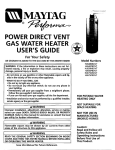
DIRECT VENT
USER'S GUIDE
GAS WATER
HEATE
For Your Safety
AN ODORANT IS ADDED TO THE GAS USED BY THIS
WATER HEATER
Model Numbers
HJ640NBDS
HJ640PBDS
I-IJ650NBDS
HJ650PBDS
WARNING: If the information in these instructions are not followed exactly, a fire or explosion may result, causing property
damage, personal injury or death.
-Do not store or use gasoline or other flammable vapors and liquids in the vicinity of this or any other appliance.
-WHAT TO DO IF YOU SMELLGAS
• Do not try to light any appliance.
• Do not touch any electrical switch; do not use any phone in
your building.
• Immediately call your gas supplier from a neighbor's phone,
Follow the gas supplier'sinstructions.
• If you can not reachyour gas supplier,callthe fire department.
-Installation and servicemust be performed by a qualified installer,
serviceagencyor the gassupplier.
FOR POTABLE WATER
•,WARNING
Improper installation, adjustment, alteration, service or maintenance can cause DEATH, SERIOUSBODILY INJURY,OR PROPERTY
DAMAGE. Refer to this manual for assistanceor consult the local
gas utility for further information.
HEATING ONLY
NOT SUITABLEFOR
SPACE HEATING
NOT FOR USE IN
MANUFACTURED
Flammable vapors may be drawn by air currents
areas of the structure to AWARNING
this app lance.
•,WARNING
from
other
I
COVER AND THEN THIS ENTIRE MANUAL BEFORE INSTALLING
READ
THE GENERAL
SAFETYHEATER.
SECTION BEGINNING ON INSIDE I
OR
OPERATING
THIS WATER
Save this Manual for Future Reference.
(MOBILE)
Caution: HOMES
Read and Follow All
Safety Rules and
Before First Use of
Operating
Instructions
This
Product.
Safety Instructions
&WARNING
The water heater must be properly vented outdoors. Never operate the water heater unless it is
vented to the outdoors and has adequate air supply to avoid risks of improper operation, explosion
or asphyx ation.
_,WARNING
HYDROGEN GAS: Hydrogen gas can be produced in
a hot water system that has not been used for a
long period of time (generally two weeks or more).
Hydrogen gas is extremely flammable and explosive.
To prevent the possibility of injury under these conditions, we recommend the hot water faucet be
opened for several minutes at the kitchen sink
_WARNING
before
appliances
which(such
are connected
to the any
hot electrical
water system
are used
as a dishwasher or washing machine). If hydrogen gas is present, there will probably be an unusual sound similar to air escaping through the pipe as the hot water
faucet is opened. There must be no smoking or open
flame near the faucet at the time it is open.
Minimum clearances between the water heater and
combustible and noncombustible construction are: 0
inches from sides, 0 inches from back, 4 inches from
front of jacket to closet door and 3 inches from top
of jacket to combustible and noncombustible ceiling,
Minimum vent clearance: 0 inches. NOTE: provide 24
inches front clearance for servicing. (See Figure 1)
Page 9.
A, CAUTION
WATER HEATERS EVENTUALLY LEAK: Installation of
the water heater must be accomplished in such a
_,WARNING
Flood damage to a water heater may not be readily
I visible or immediately detectible. However, over a
period of time a flooded water heater will create
dangerous conditions which can cause DEATH, SERIOUS BODILY INJURY, OR PROPERTY DAMAGE.
manner that if the tank or any connections should:
leak, the flow of water will not cause damage to the
structure. For this reason, it is not advisable to install
the water heater in an attic or upper floor. When
such locations cannot be avoided, a suitable drain
pan should be installed under the water heater. Such
a drain pan must have a minimum length and width I
of at least 2 inches greater than the water heater
dimensions and must be piped to an adequate drain.
Drain pan depth must allow for access to the outer
doors for lighting the pilot and servicing the burner.
Under no circumstances is the manufacturer
or
Maytag to be held liable for any water damage in'
connection with this water heater.
Contact the Maytag dealer from whom the appliance was purchased or call Maytag Customer Service
at 1-800-788-8899
for an authorized servicer to
replace a flooded water heater. Do not attempt to
repair the unitJ It must be replaced!
A WARNING
INSULATING JACKETS: When installing an external
water heater insulation jacket on a gas water
heater:
a. DO NOT cover the temperature-pressure
relief
valve.
b. DO NOT put insulation over any part of the top of
the gas water heater.
c. DO NOT put insulation over the gas control valve
or gas control valve/burner cover, or any access
areas to the burner.
d. DO NOT let insulation around the gas water
heater to get within 8 inches of the floor to allow
access to the burner assembly.
e° DO NOT cover or remove operating instructions,
and safety related warning labels and materials
affixed to the water heater,
Failure to heed this will result in the possibility of a
fire or explosion.
4
Table of Contents
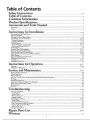
Safety Instructions ................................................................................................................................
2-4
Table of Contents .........................................................................................
5
Customer Information ...........................................................................
6
Product Specifications
................................................................................
6
Accessories and Tools Needed ...............................................................
7
Accessories ............................................................................................................................................................................
Tools .....................................................................................................................................................................................
Instructions
for Installation
7
7
.....................................................................
_-_
Removing the Old Water Heater ..........................................................................................................................................
Typical Installation ................................................................................................................................................................
Locating the New Water Heater .........................................................................................................................................
Combustion Air and Ventilation ...................................................................................................................................
Venting Clearances .....................................................................................................................................................
Optional Wire Grill ..........................................................................................................................................................
Flue Extensions .............................................................................................................................................................
Vertical (Extension Kit) Height ..................................................................................................................................
Horizontal (Extension Kit) ...............................................................................................................................................
All Installations ...................................................................................................................................................................
Standard Vent Kit Installation .......................................................................................................................................
Optional Vertical Kit Installation ..................................................................................................................................
Optional Horizontal Kit Installation .............................................................................................................................
O_tlonal Vertical and Horizontal Kit Installation .........................................................................................................
water Piping .......................................................................................................................................................................
Temperature-Pressure Relief Valve .....................................................................................................................................
8
9
10
11, 12
11, 12
12
12, 13
12, 13
13
14
14-I7
17-21
21-25
25-29
30
31
Fillip. the Water Heater .....................................................................................................................................................
Gas Piping ....................................................................................................................................................................
Installation Checklist ..........................................................................................................................................................
32
32, 33
34
Instructions
for Operation .........................................................................
a5-3_
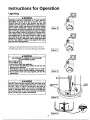
Lighting ........................................................................................................................................................................
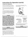
Temperature Regulation ......................................................................................................................................................
Service and Maintenance
.......................................................................................................
Venting System Inspection ..................................................................................................................................................
Burner Inspection ...............................................................................................................................................................
Burner Cleaning ..................................................................................................................................................................
LR Gas Control Valve and Burner Assembly Replacement information ..........................................................................
Draining ..............................................................................................................................................................................
Anode tcod Inspection ........................................................................................................................................................
Temperature-Pressure Relief Valve Operation ....................................................................................................................
Drain Valve Washer Replacement ......................................................................................................................................
Housekeeping .....................................................................................................................................................................
Service .................................................................................................................................................................................
Troubleshooting
....................................................................................................................................
Start Up Cor_ditioas ............................................................................................................................................................
Condensation ....................................................................................................................................................................
Smoke/Odor .....................................................................................................................................................................
Thermal Expansion ...........................................................................................................................................................
Strange Sounds .................................................................................................................................................................
Operational Conditions ................................................................................................................................................
_meUcvWater
.....................................................................................................................................................................
'_lir m Hot Water
Faucets ...............................................................................................................................................
High Temperature Shut Off System .................................................................................................................................
Not
Hot Water .........................................................................................................................................
WaterEnoch
Is xoo or
HotNo..............................................................................................................................................................
Leakage Checkpoints ..........................................................................................................................................................
35, 36
37
38-40
38
38
38
39
39
39
40
40
40
40
41-44
41
41
41
41
41
42, 43
42
42
42
42
43
44
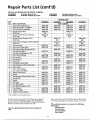
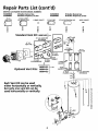
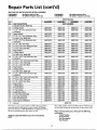
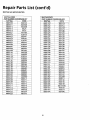
Repair Parts List ......................................................................................
46-_0
Warranty .........................................................................................................
52
5
Customer Information
Thank You for purchasing a Maytag water heater,
cannot put everything on the first few pages, READ THE
ENTIRE MANUAL BEFORE ATTEMPTING TO
INSTALL OR OPERATE THE WATER HEATER.
The installation must conform with the instructions in this
manual; gas company rules; and Local Codes, or in the absence
ofLoca/Codes, with the current edition of the National Fuel
Gas code, ANSI Z223.1, also referred to as NFPA 54. This
Properly installed and maintained, it should give you years of
trouble free service. It is strongly suggested that this new water
heater be professionally installed, contact Maytag Customer
Service (1-800-788-8899) for recommended installers,
Abbreviations
Found In This Instruction
Manual
CSA - Canadian Standards Association
ANSI - American National Standards Institute
NFPA - National Fire Protection Association
publication is available from your local government or public
library or gas company or by writing NFPA, Batterymarch
Park, Quincy, MA 02269.
• After reading this manual you have any questions or do not
understand any portion of the instructions, call Maytag
Customer Service at 1-800-788-8899 for an authorized servicer.
&WARNING
This gas-fired water heater is design certified by
CSA INTERNATIONAL
under American National
Standard/CSA Standard for Gas Water Heaters ANS
Z21.10.1 • CSA 4.1 (current edition). The installation
must conform with this manual, Local Codes and
with the current edition of the National Fuel Gas
Code, ANSI Z223.1,
This publication is available from your local government or public library, gas company, or by writing'
NFPA, Batterymarch Park, Quincy, MA 02269.
I
• Carefully plan the place where you are going to put the water
heater. Correct combustion, vent action, and vent pipe installation are very important in preventing death from possible carbon monoxide poisoning and fires.
Examine the location to ensure the water heater complies with
the "Locating the New Water Heater" section in tbJs manual.
• For California installation this water heater must be braced,
• Read the "Safety Instructions" section, pages 2, 3 and 4 of this
manual first and then the entire manual carefully.If you don't
follow the safety rules, the water heater will not operate proper13_It could cause DEATH, SERIOUS BODILY INJURY
AND/OR PROPERTY DAMAGE.
anchored, or strapped to avoid tailing or moving during an
earthquake. See instructions for correct installation procedures.
Instructions maybe obtained from your local dealer, wholesaler,public utilities or California Office of the State Architect,
400 P Street, Sacramento, CA 95814.
• This manual contains instructions for the installation, operation, and maintenance of the gas-fired water heater. It also con-
• Massachusetts Code requires this water heater to be installed in
accordance with Massachusetts 248-CMR 2.00: State
tains warnings that you must read and be aware of through out
the rnanual. All wamlngs and all instructions are essential to the
proper operation of the water heater and your safety. Since we
Plumbing Code and 248-CMR 5.00.
• Complies with SCAQ_MD rule #1121 and districts having
equivalent NOx requirements.
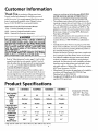
Product Specifications
• Model
HJ640NBDS
HJ640PBDS
HJ650NBDS
HJ650PBDS
Tank Capacity
In Gallons
40
40
50
50
Natural
Propane
Natural
Propane
40,000
40,000
48,000
44,000
41
41
49
45
6" (3")
21"
6" (3")
21"
6" (3")
21"
6" (3")
21"
483/4"
48'/,"
61"
61"
Type of
Gas
B.T.U.
Rate
Recovery Rate
In Gals Per Hour
@ 90°F Rise
Vent Inlet
(Outlet) Size
Diameter
Height To
Top of
Water Heater
• High altitude models have a B.T.U./Recovery Rate 10% less than shown.
6
AVAILABLE OPTIONS:
Suffix "W" - Heat Traps
* Suff,x "D" - High Altitude
Accessories and Tools Needed
Accessories
To simplify
the installation
Maytag
has available the installa-
tion parts shown below. You may or may not need alI of these
accessoriesdependingon yourtypeof installation.Call
Maytag Customer Service
authorized installer.
at 1-800-788-8899
for an
DRAINPANSAVAILABLEIN 22" DIAMETER
(PARTNUMBER 66001011) FORWATER
HEATERSHAVING A DIAMETER20° OR LESS,
24" DIAMETER(PARTNUMBER 66001105) FOR
WATERHEATERSHAVING A DIAMETER22"
OR LESSAND 28" DIAMETER(PARTNUMBER
66001012) FORWATERHEATERSHAVING A
DIAMETER26_'OR LESS
EXPANSIONTANKSFORTHERMALEXPANSION
CONDITIONSAVAILABLEIN 2 GALLON(PART
NUMBER66001013) AND 5 GALLON(PART
NUMBER66001014) CAPACITY
Tools
You may or may not need all of these tools, depending
type of installation.
hardware store.
These
tools can be purchased
• Pipe Wrenches
(2) 14"
• Tin Snips
• 6 Foot Tape of Folding
• Garden Hose
• Drill
• Pipe dope or Teflon
• Screwdriver
ADDITIONAL
on your
TOOLS
NEEDED
WHEN SWEAT SOLDERING
* Tubing Cutters or Hacksaw
• Propane Torch
at your local
• Soft Solder
• Emery Cloth
• Wire Brushes
Rule
GARDENHOSE
Tape
_
_
6 FOOTTAPE
P,PE
Flux
HACKSAW
WRENCH
ROLLOF TEFLONTAPE
(USE ONLYON WATER
CONNECTIONS)
_
SLOT-HEADSCREWDRIVER
• Solder
3/4" WIRE BRUSH
1/2" WIRE BRUSH
_
PROPANETORCH
TIN SNIPS
_;_
ROLLOF LEADFREE
SOFTSOLDER
PHILLIPSSCREWDRIVER
PIPEDOPE(SQUEEZETUBE)
(USE FORWATERAND
GAS CONNECTIONS)
ROLLOF EMERY
CLOTH
7
SOLDERFLUX
TUBINGCU'I'I'ER
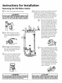
Instructions for Installation
Removing the Old Water Heater
@
Turn "OFF" the gas supply to the water heater.
@
iI WARNING
If the main gas line shutoff servingall gas appliancesis used,
alsoshut "OFF"the gasat eachappliance.Leaveall gasappliancesshut"OFF"untilthe waterheater nsta at on iscomplete,
Disconnect the vent pipe from the draft hood, if provided, where they connect to the water heater. In most
installations
vent pipe(s)
canare
be removed.
lifted off Dispose
after anyof
screw or othertheattached
devices
the draft hood, if provided. The new water heater has a
vent kit which must be usedfor proper operation.
a. If you have copper piping to the water
heater, the two copper water pipes can
four inches away from where they connect to the water heater. This will
avoid cutting off the pipes too short.
@
@
the water to the water
Turn
heater. Some installations require that
house.the
water be turned offto the entire
to make
the
Check again
sure
gas supply is "OFF" to the water heater. Then
{J_
_
Q1)
now completely disconnected and
ready to be removed.
la_ I_
ll_l
from the gas control valve,
hose to the water heater drain
Attach a
valve and put
in a floor
disconnect
the the
gas other
supplyend
connection
drain or outdoors. Open the water
heater drain valve. Open a nearby hot
water faucet which will relieve pressure
in the water heater and speed draining,
necessary. Disconnect the temperaturebe cut with a hacksaw approximately
pressure relief valve drain line. When
the water heater
is drained,
Additional
cuts can
be madedisconnect
later if
the hose from the drain valve. Close
the drain valve. The water heater is
@
b. If you have galvanized pipe to the water
with a pipe wrench at the union in each
line. Also disconnect the piping
remaining to the water heater. These
pieces should be saved since they may
be
needed
whenthereconnecting
the pipes
new
heater,
loosen
two galvanized
water heater. Disconnect the temperature-pressure relief valve drain line.
When the water heater is drained, disconnect the hose from the drain valve.
Close the drain valve. The water heater
_
r;LW'° bmPrleCte°lv
and
WARNING
Thewater passingout of the drainvalvemay beextremelyhot.
Toavoidbeingscalded,makesureall connections
aretight and
that the waterflow isdirectedaway fromanyperson,
& CAUTION
Mineralbuildupor sedimentmay haveaccumulatedin the old I
water heater.Thiscausesthe water heaterto be muchheavier
8
than normaland th s residue,f spi ed out,coud causestan ng.
Instructions for Installation (cont'd)
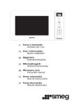
Typical Installation
CHECK ALL CONNECTIONS
PRIETY AND SAFETY.
FOR LEAKS. CONSULT THE LOCAL UTILITY COMPANY
TO EXAMINE
INSTALLATION
FOR PRO-
i VACUUM RELIEFREQUIREDBY SOME CODES
' (REFERTO LOCALCODES)
VENTTO
OUTDOORS
WATERINLET
\\
\\
TEMPERED -- _'_
WATEROUTLET \\
\\
\\
MtXtNGVALVE"
\\_
\\
_\
GAS
SUPPLY
RELIEFVALVE
\\
\\
\\
-DISCHARGEPIPE
(Do not cap or plug)
\\
\\
\\
\\
\\
\\
\\
\\
DRAIN PAN
This appliance
sideredsoitable
Water
(Potable)
HOTTER
has been design certified
for:
Heating:
WATER
as complying
A]J models are "considered
CAN
SCALD:
AWARNING
temperature
which will
intended
to produce
hot
dish
washing,
end other
and permanently
injure
people are more likely to
Water
TO SUITABLEDRAIN
with American
suitable
heaters
for water (potable)
are
Standard/CSA
Standard
for water heaters and is con-
heating."
This water
satisfy Water
clothes heated
washing,
water.
to a
sanitizing
needs can scald
you upon contact.
Some
be permanently
injured by
heater shall
not be connected
A WARNING
non-potable
heating appliance.
ing systems water
or component(s)
previously
to any heatused w th a
_, WARNING
!hot
water thethaninfirm,
others.
These include the elderly,
children,
or physically/mentally
handicapped. If anyone using hot water in your home fits
into one of these groups or if there is a local code or
state law requiring
a certain temperature
water at
the hot water tap, then you must take special prei cautions. In addition
to using the lowest possible
temperature
setting that satisfies your hot water
needs, a means such as a mixing valve, should be
used at the hot water taps used by these people or
at the water heater. Mixing valves are available
at
plumbing
supply or hardware
stores. Follow manufacturers instructions
for installation
of the valves,
Before
changing
the factory
,stat, read the "Temperature
this manual.
National
iToxic chemicals such as used for treatment
of boilers
or non-potable
water heating appliances shall never
be introduced
into a potable water space heating|
system.
NOTE: To protect against untimely corrosion of hot and
cold water fittings, it is strongly recommended
that di-electric unions or couplings be installed on this water heater
setting
on the thermoRegulation"
section in
when connected
9
to copper pipe.
I
J
Instructions for Installation (cont'd)
Locating the New Water Heater
• The location selection must provide adequateclearancesfor
You should carefully choose an indoor location for the new water
heater, because the placement is a very important consideration
servicing and proper operation of the water heater.
&WARNING
[
for the safety of the occupants in the building and for the most
economical use of the appliance. Thiswater heateris not foruse
inmanu_ctured(mobile)homesoroutdoorinstallation.
Whether replacing an old water heater or putting the water
heater in a new location, the following critical points must be
[ Propellants
of ae_and
volatile
com|pounds, (cleaners, chlorine based chemicals, refrig/erants, etc.) in addition to being highly flammable
in many cases, will also change to corrosive
hydrochloric acid when exposed to the combustion
products of the water heater. The results can be
observed.
[hazardous,
and a so cause
product
fa ure.
The location selected should be indoors as dose as practical to
AWARNING
the outside wall to which the water heater vent is going to be
This water heater must not be installed directly on
carpeting. Carpeting must be protected by a metal
or wood panel beneath the appliance extending
beyond the full width and depth of the appliance by
at least 3 inches (76.2mm) in any direction, or if the
appliance is installed in an alcove or closet, the
entire floor must be covered by the panel. Failure to
heed this warning may result in a fire hazard.
installed through, and as centralized with the water piping systern as possible. The water heater, as all water heaters, wiU eventually leak. Do not install without adequate drainage provisions
where water flow will cause damage,
ACAUTION
WATER HEATERS EVENTUALLY LEAK: Installation of
the water heater must be accomplished in such a
manner that if the tank or any connections should
leak, the flow of water will not cause damage to the
structure. For this reason, it is not advisable to install
the water heater in an attic or upper floor. When
such locations cannot be avoided, a suitable drain
pan should be installed under the water heater. Such
a drain pan must have a minimum length and width
of at least 2 inches greater than the water heater
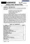
AWARNING
Minimum clearances between the water heater and
combustible and noncombustible construction are: 0
inches from sides, 0 inches from back, 4 inches from
front of jacket to closet door and 3 inches from top I
of jacket to combustible and noncombustible ceiling. I
Minimum vent clearance: 0 inches. NOTE: provide 24
dimensions
and must
pipedfor
to access
an adequate
Drain
pan depth
mustbeallow
to the drain,
outer
doors for lighting the pilot and servicing the burner.
Under no circumstances is the manufacturer
or
inches front clearance for servicing. (See F gure 1).
Ventto
Maytag to be held liable for any water damage in
connection with this water heater.
ou__
0-m_:._;,l_0" rain. >
AWARNING
INSTALLATIONS IN AREAS WHERE FLAMMABLE LIQUIDS (VAPORS) ARE LIKELYTO BEPRESENTOR STORED
(GARAGES, STORAGE, AND UTILITY AREAS, ETC):
Flammable liquids (such as gasoline, solvents, propane
(LP) or butane, etc.), all of which emit flammable
vapors, may be improperly stored or used in such
areas. The gas water heater pilot light or main burner
can ignite such vapors, The resulting flashback and fire
_i_j"
_
0"
outdoors
_- --
can cause death or serious burns to anyone in the
area, as well as property damage.
If installation in such areas is your only option, then
the installation must be accomplished in a way that
the pilot flame and main burner flame are elevated
from the floor at least 18 inches. While this may reduce
the chances of flammable vapors from a floor spill
being ignited, gasoline and other flammable substances should never be stored or used in the same
room or area containing a gas water heater or other
open flame or spark producing appliance.
NOTE: Flammable vapors may be drawn by air currents
[,from other areas of the structure to the app lance.
_
--°m_n"
....._.........
........
I
I
I Figure 1 ]
10
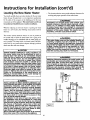
Instructions for Installation (cont'd)
Combustion Air and Ventilation
When determining the installation location for a direct vent
water heater, snow accumulation and drifting should be considered in areas where applicable.
any overhang
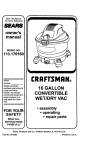
VENTING CLEARANCES
18"mJn.
• 18" minimum in all directions from any obstruction that may
interfere.
I Figure2 ]
• 18" minimum from the ground and 12" from ceiling overhangs.
Figure 2.
• The direct vent terminal shall terminate at least 3 feet above any
gravityair inlet into the building.
* 12" minimum below any door, window or gravity air inlet into the
building.
IF LESS
_
• 18"minimumfromothergravityornaturalapplianceoutletvents
-._1_ _'_'_
* 9" minimum horizontally from or aboveany door, window or
• 36" minimum from any outlet vents when directly below or 45° to
either side of center line. Figure 5, page 12.
"i -N120
CT
VE'V_N_
_'_
9"__
TERMI
IR
• 36" minlmum in all directions from any other forced air appfiance
when
ab°ve5,°r4"page
135°t°
outlet dimcdy
vent. Figure
12. either side °fcenter line"Figum
DIRE__
[ Figure 3 ]
/_
_FtRC[DTA
• The location selection must provide clearancesfor servicing and
proper operation of the water heater. Figure 6, page 12.
• Vent termination must not be within 4 feet of any items such as
/
gas meters, gas valves or other gas regulating equipment.
WARNING
such
as gas meters, gas valves or other gas regulating
equipment.
appliance.
_vented
THEN THE DIMENSION
a_
Any gravity or natural
IS
_
18"min._ '
I
/-
i
INCREASED TO 24"
I
_--
Failure to have required clearancesbetween vent piping I
and combustible material will result in a fire hazard.
I
II Figure 4 II
11
_..z_'_'\
"
\
t3_°
_
---
\
_
13s°--
---
--
,,
Instructions for Installation (cont'd)
Combustion Air and Ventilation
(cont'd)
Flue Extensions
There are three optional extension kits available. Any combination of the three kits can be chosen; however, only one kit
(See Figures 8 & 9.)
can be used vertically and/or horizontally.
4_
/36" min.if withid"
thisiarea \
e
_
36" min. within a 360° rad_
if vent is a forced air appliante outlet vent.
Unless otherwise specified at the time of ordering, a standard
shipped within the water heater carton.
extension kit (66001422) is individually packaged and
Any other gravity or natural
appliance outlet vent
POSSIBLE
EXTENSION
COMBINATIONS
[Figure,
]
-Must maintain
adequate
service
and maintenance
accessibility._
__ I'''"
_
_
_.¢
_o)
_
"_
i
_
\
/
TAL
TWO VERTICAL
KITS
NOT OK
'_
J
J
KITS
NOT OK
i_!_N i%_
IFigure"
I
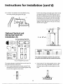
Optional Wire
i_
• _
-------
available for vent
RT, L
.--,on
_U_
°
OK
0
HORIZONTAL
I----I
KITOK
_
Grill
i
i
accidentally, or is accessible to small children, installation of a
_A_'T--"_C
AL KITAND
[ I
ONEHORIZONTAL
I I
K/r OK
protective
is recommended.
codes
may
When the vent
watercover
heater
vent cap is low Some
enoughlocal
to be
touched
require a vent cap cover. Figure 7 shows the optional wire vent
cap protector available from the water heater manufacturer.
I Figure8
A wire mesh chain link fence (as shown in Figure 7) may be
used instead of the factory cover. Care should be taken to
maintain adequate ventilation around the vent cap. If a chain
J4_
I'--I
Horizontal Vent Kit be used.
VERTICAL
NOttobeused
asa storage area
I
_k WARNING
At no time can more
than one Vertical and/or one
link fence is installed, it must not be used as a storage area for
items that may block proper ventilation.
/
I
(EXTENSION
I
I
KIT) HEIGHT
It is simple to determine which kit is needed for vertical height.
Take the total height (to the top of the flue) required and com-
_
_-I-
pating that to "F dim." in the chart #1, it can be determined
Failure to have required clearances between vent
piping and combustible material will result in a fire
hazard.
]
Obstructions and deteriorated vent systems
present serious health risk or asphyxiation.
12
WARN, G may
Instructions for Installation (cont'd)
I
A
r
66001423
66001424
[
6600142S
HORIZONTAL (EXTENSION KIT)
simply plug the dimensions "D" and "G" into the equation
,_v-, [r_
_7_
below.size
The
answer
"E" should
then be located
in chart the
#2. kit
The
range
in which
"E" dimension
falls indicates
"G" -- The distance wanted between the edge of the water
heater and the inside edge of the wall
"E" = The distance the extension kit must be able to extend
_
"
e!ste!teithe_r
"
)U
The Equation
D + G =E
"D"that
should
length.=
The wall
be used
thickness
horizontally to obtain the desired
__
Iigure'
I one::°°0',::;
NOTE: Only
vent kit can be used horizontally
,
and/or
CHART #2
!0
DIMENSION
40-50 Gal.
VENT KITS
MIN
MAX
66001422-Std.
3½
10
66001423
10
15Y2
66001424
15½
26½
66001425
26½
48
, _
..
CHART #1
in1000'SNAT.
_
40/40
BTU's _
48144
*GAL.
CAP.
in 1000's
*BTU'S
NAT
A
B
C
40
50
40/40
48144
483h
61
413/,,
54
21
21
*See models and rating plate attached to the water heater for
&WARNING
_MIN'
[ MIN '
'
I MAXI
I MAX I
77 I 88 I 88 I 110 I
893h]100%11003h
1122V4
[
I
Be sure vent pipe is properly connected to prevent I
escape of dan_ierous flue gases which could cause
specific
number and other detailed informafion
deadlymodel
asphyxiation.
*See model and rating plate attached to the water heater for
specific model number and other detailed information.
A WARNING
Obstructions and deteriorated vent systemsmay present
serious health risk or asphyxiation.
13
]
L
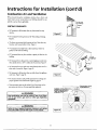
Instructions for Installation (cont'd)
All Installations
Furease
ofassembly
theinstalladon
ofthe
various
kit
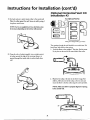
Standard Vent Kit
Installation #1
combinations has been broken into individual sections,
The two steps below are common to all installations.
Once these have been performed, you need only to refer
Standard Vent Kit 66001422
o.ee
oo.teoyou
,
Installation Using Vent Kits:
1. Standard Vent Kit 66001422 ...........................
2. Optional Vertical Vent Kit
with Standard Vent Kit ..................................
3. Optional Horizontal Vent Kit ........................
4. Optional Hotizontal
and Vertical Vent Kits ....................................
CUTTING
WALL
THE OPENING THROUGH
Page 14
_
Page 17
Page 21
Page 25
*Eachpart is stampedwith a part number
THE OUTSIDE
The opening through the wall should be cut at this time. If it
hasn't been, refer back to that section.
After thoroughly reading the "Locating the New Water
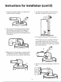
Heater" section of this manual and you have chosen a suitable water heater installation site, use the chart below to
1. Lock the elbow to the straight 3" flue pipe. Set this assembly in place on the end of the water heater's flue collar.
determine dimensions for the opening in the wall.
Cut a C/4" diameter hole completely through the outside
wall.
2. Mark the flue collar at the slots in the elbow. Using a #22
drill hit, drill holes into the flue collar at the two slots and
secure the elbow to the flue collar using the screws provided.
WATER HEATER ATTITUDE
There is a certain amount of variance with regard to the direction the water heater faces,
NOTE: Make sure elbow is properly aligned to opening
in the outside wall.
Standing in front of the water heater (gas control facing you),
set the 3" diameter elbow (slotted end) on the flue. This will
assembly to the opening in the wafl and more importantly any
possibility of interference of venting and water piping.
give you a better understanding of the relation of the vent
The direction of the water heater can now be made. Also con-
__//)I_
"_"
_
_
maintenance accessibility are retained.
sider the gas control valve to insure installation, lighting, and
0" --__"I_S
14
_
_
_ -#
Instructions for Installation (cont'd)
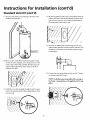
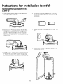
3. Using the tube of sealant supplied, run an ample amount
6. The standard vent kit includes a 6° diameter extension
around the oval flare of the jacket,
pipe which is used when "E" dimension is over 6V2".
4. First remo e the 3 honzontaI extension from the elbow.
X
Starting with the long end (with four securing holes),
place the 6" diameter vent elbow over the 3" diameter
elbow. Bend the round end "oval_ to fit the flared oval end
of the jacket top.
I
7
_]
--_
/
I
_ ,__
,,
If_E " dimension is less than 6VI' move to next step.
extension pipe (crimped end) to the 6" diameter vent
elbow and secure using two sheet metal screws. Using the
tube of sealant supplied, run an ample amount around the
joint to insure a good seal.
_)_
If"E" dim ensionis over6_/I', assemble the 6" diameter
t
5. Making sure the 6" diameter elbow is centered around the
3" diameter flue, secure the 6" diameter vent pipe using
four sheet metal screws at the connection of the jacket top.
(_)-?__
__
_-'"
__
8. eSll_do;ihevent collar (to be installed later)over the 6" vent
15
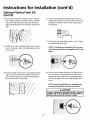
Instructions for Installation (cont'd)
Standard
Vent Kit (cont'd)
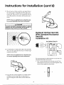
9. Place the water heater at the opening in the wall, at the
predetermined clearance,
12. We have supplied 4 wood screws to temporarily attach the
collar to the exterior wall of the building. However, other
types of screws may have to be substituted depending on
\\
\\
\\
\\
'\ \
13. Insert the 3" diameter flue extension pipe into the vent
collar assembly (flared & notched end first) and lock (turn
clockwise to lock studs to slots) the flue extension pipe to
\\
\\
_
_
the flue elbow.
10. Move outdoors with all the remaining vent parts. Using
the tube of seal.ant supplied, run an ample amount on the
inside surface of the collar assembly that will contact the
exterior wall and also fill the bead on the end of the 6"
diameter vent collar.
_
::
.....
....
_ ....
ter extension pipe and O-ring.
NOTE: To facilitate ease of assembly of the vent cap to
the 3" pipe, a soap solution can be applied to the O-ring
gasket.
__
14. Connect the vent cap by sliding its end over the 3" diame-
11. In:t tallt:htheVenteCOsUo_
na:sTolz_yeltbho_u(ghe;ehediwa_g
,oCOnh_:h
VJ_/////_
16
Instructions for Installation (cont'd)
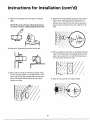
15. The vent cap has 4 holes around the outer edge. Remove
the 4 screws used to temporarily attach the collar to the
exterior wall. Then secure the vent cap assembly with the
vent collar assembly to the exterior wall using the same 4
screws.
NOTE: Screws are suppfied; however, substitution may
be necessary depending on the exterior wall material.
A CAUTION
To prevent unlocking the previously installed 3" diameter
extension, the vent cap assembly must be rotated in a
c ockwise mot on when the vent cap s nsta ed.
OW/_ihO
_(/n_er _idca/oVre22K ia_
Any Optional Vent Kit
16. Go back indoors to attach inside collar to the inside wall.
Place the collar against the wall. Secure to wall by using 4
long sheet metal screws.
_
_
UU
NOTE: Screws are supplied; however, substitution may
be necessary depending on the interior wall material.
The opening through the wall should be cut at this time. If it
hasn't been, refer back to that section.
telescoping flue sections are set and locked together using
the two screws supplied as shown below.
I
1. First it must be determined how far the vertical (3" dia.)
17. Using the tube of sealant supplied, run an ample amount
of sealant around the edge of the vent pipe where it is
inserted through the inside collar to seal air drafts from
wall.
II I
____
17
Instructions for Installation (cont'd)
Optional Vertical Vent Kit
(Cont'd)
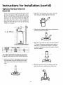
Use the chart, drawing and simple equation below to find
the length of expansion of the telescoping flue sections,
Because of manufacturing tolerances, place the telescoping
extension on the water heater and adjust the height ("X"
Dimension) and mark the point. Once the length has
been determined,
lock the two sections together by
3.
drilling
holes
(180" apart) in the pipe and securing
with
the two
screws
supplied.
7--L-_-10"
' _
C- A- 10"= X
*GALLON
CAPACITY
40
50
H-6,/,-
i :....
H
_
_
!I
4. Using
amoUntaround
the
thetube
ovalofflare
sealant
of thesupplied,
j acket. run an ample
A _
*BTU'sNAT.
in 1000's
40140
48/44
_
,1
.a_
]'-- _
Sfide the 6"vent telescoping section apart to reveal the
beads. Using the caulking supplied, fill the beads.
%" from
X dimension
usedthe
earlier
andsection.
this gives
the
5. Place
the the
6" vent
section over
3" flue
Subtract
length of the 6" vent extension. Slide the 6" vent extension apart to this dimension and lock it together using the
two screwssupplied.
A
48%
61
*See models and rating plate attached to the water heater
for specific model number and other detailed information.
_
2. Set the vertical (3" dia.) telescoping flue section in place
on the flue collar. Using a #22 drill bit, drill two holes
(180 ° apart) and secure the vertical assembly to the flue
coUaL
6. Bend the round end of the 6" vent extension oval at the
jacket top and secure it using four sheet metal screws.
18
Instructions for Installation (cont'd)
7. Place the 3" elbow on the flue extension.
10. If"E" Dimension is less than 61/2# move to next step.
NOTE:
Make sure elbow is properly aligned to opening
If "E" dimension is over 6V:', assemble the 6" diameter
in the outside wail.
extension pipe to the 6" diameter vent elbow and secure
Mark the 3" dia. end of the flue extension at the slots the
using two sheet metal screws. Using the tube of sealant
elbow. Using a #22 drill bit, drill holes into the flue extension at the two slots and secure the elbow to the flue
supplied, run an ample amount around the joint to insure
a good seal.
extension using the screws provided.
__t_o!s,
_[
___
3.1.Slide the vent collar (to be installed later) over the 6" vent
elbow.
8. Making sure the 6" diameter elbow is centered around the
"
3" diameter flue, sec ure the 6 " diameter
vent pipe using
two sheet metal screws at the connection of the elbow and
6" vertical extension.
12. Place the water heater at the opening in the walI, at the
predetermined clearance.
9. The
standard
vent kit
includes
a 6# diameter
extension pipe which is
used when "E" dimension
[_J[
_1
,_
over 6V:'.
\\
19
Instructions for Installation (cont'd)
Optional Vertical Vent Kit
(cont'd)
13. Move outdoors with all the remaining vent pans. Using the
tube of sealant supplied, run an ample amount on the inside
surface of the collar assembly that will contact the exterior
wall and also fill the bead on the end of the 6" diameter vent
16. Insert the 3" diameter flue extension pipe into the vent
collar assembly (flared &. notched end first) and lock (turn
clockwise to lock studs to slots) the flue extension pipe to
the flue elbow.
collar.
/
1
17. Connect the vent cap by sliding its end over the 3" diameter extension pipe and O-ring.
14. Install the vent collar assembly through the wall, connecting it to the extension and/or elbow (depending on which
one was used),
NOTE: To _¢ili_ate ease of _ssembly of the vent cap to
the 3" pipe, a soap solution can be applied to the O-ring
gasket.
15. We have supplied 4 wood screws to temporarily attach the
collar to the exterior wall of the building. However, other
types of screws may have to be substituted depending on
the construction of the external wall.
18. The vent cap has 4 holes around the outer edge. Remove
the 4 screws used to temporarily attach the collar to the
exterior wall. Then secure the vent cap assembly with the
vent collar assembly to the exterior wall using the same 4
screws.
A CAUTION
j__41
/
/
I TOprevent
extension, unlocking
the vent cap
be rotated
in a
the assembly
previouslymust
installed
3" diameter
[ clockwise motion when the vent cap is installed.
20
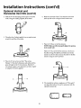
Instructions for Installation (cont'd)
Optional Horizontal
Installation #3
19. Go back indoors to attach inside collar to the inside wall.
Vent Kit
Any Optional Vent Kit
NOTE:
supplied; however, substitution
may
lottgPlace
4sheet
theScrews
collaragainstthewaU.Secureto
metaJ,are
screws.
waUbyusing
be necessary depending on the interior wall material.
___
_
_
_
parts are
not used
These
_
*Each part is stamped with a part number
The opening through the wall should be cut at this time. If it
hasn't been, refer back to that section.
1. Lock the elbow to the straight 3" flue pipe. Set the assembly in place on the end of the water heater's flue collar.
20. Using the tube of sealant supplied, run an ample amount
of sealant around the edge of the vent pipe where it is
inserted through the inside collar to seal air drafts from
=,_
._ _ __
wall.
2. Mark the flue collar at the slots in the elbow. Using a #22
drill bit, drill holes into the flue collar at the two slots and
secure the elbow to the flue collar using the screws provided.
NOTE: Make sure elbow is properly aligned to opening
in the outside wall.
21
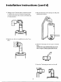
Instructions for Installation (cont'd)
Optional
(Cont'd)
Horizontal
Vent Kit
3. Using the mbe ofsealant supplied, run an ample amount
around the oval flare of the jacket,
6. The standard kit includes a single piece of3" flue and 6"
vent pipe which will not be used in conjunction with the
horizontal kit.
4. First remove the 3" horizontal extension from the elbow.
7. Slide the vent collar (to be installed later) over the 6" vent
elbow.
Starting with the long end (with four securing holes),
place the 6" diameter vent elbow over the 3" diameter
of the jacket
elbow.
Bend top.
the round end "oval" to fit the flared oval end
_
_/_
"_
/"_"',_
8. Place
the water clearance.
heate r at the opening in the wall, at the
predetermined
3" diameter flue, secure the 6" diameter vent pipe using
four sheet metal screws at the connection of the jacket top.
_
E
\\
5. Making sure the 6" diameter elbow is centered around the
_4_
\\
22
0_
_111
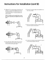
Instructions for Installation (cont'd)
9. Slide the 6" telescoping vent section apart to reveal the
12. Install the vent collar assembly through the wall, connect-
beads,
ing it to the 6" telescoping extension. Remember, the
extension is not connected yet and it may be necessary to
go back indoors and push it back up for a tight fit to the
coUar.
NOTE: The section of 6" pipe with beads will connect
to the elbow. Using the caulking supplied, fill the beads,
10. Insert the 6" telescoping vent section into the wall.
I1'
I3. We have supplied 4 wood screws to temporarily attach the
II
II _. _[&
[L
[I
I
.....
collar to the exterior wall to the building. However, other
II
_
types of screws may have to be substituted depending on
11. Move outdoors with all the remaining vent parts. Using
the robe of sealant supplied, run an ample amount on the
inside surface of the collar assembly that will contact the
¢'<__,-r
-J
.....
exterior wall and also fall the bead on the end o£the 6"
diameter vent collar.
14. Place the vent cap in the vent collar assembly.
23
Instructions for Installation (cont'd)
Optional Horizontal Vent Kit
(cont'd)
15. The vent cap has 4 holes around the outer edge. Remove
the 4 screws used to temporarily attach the collar to the
exterior wall. Then secure the vent cap assembly with the
vent coUar assembly to the exterior wall using the same 4
18. Using a #22 drill bit, drill holes 180 ° apart at the connection point of the two 3" flue extensions. Then using 2
screws provided, lock these pipes together.
screws.
be necessary, depending on the exterior wall material.
/_
I
i
NOTE: Screws are supplied; however, substitution may
i _tt[.
19. Now the 6" vent extension pipes can be expanded to connect at the vent elbow.
16. Move indoors to complete the assembly process.
and install the 3" extension by first slipping the end with
the O-ring approximately 1V," into the end of the vent
cap. Lock the other end of the 3" extension to the studs in
the elbow.
NOTE: To facilitate ease of assembly of the vent cap to
the 3" pipe, a soap solution can be applied to the O-ring
17. Collapse the 6" flue extension assembly as shown below
gasket.
j_/A,_//
20. Pull the vent collar from the elbow to be against the wall
and secure it using the screws provided.
24
Instructions for Installation (cont'd)
21. Lock the 6" vent extension to the vent elbow by using
Use the chart, drawing and simple equation below to find
two screws provided, placiag them 1800 apart,
the length of expansion of the telescoping flue sections.
Because of manufacturing tolerances, place the telescop-
_"/_'
("X" Dimension) and mark the point. Once the length
has been determined, lock the two sections together by
drilling two holes (180" apart) in the pipe and securing
with the screws supplied.
2"_
--
__._
ing extension on the warer heater and adjust the height
Optional Vertical and
Horizontal Vent Kit
Installation #4
Any TWO Optional
c- A- 10"=X
Vent Kits
I
I
2
CAPACITY
40
used
NAT.
40140
A
48%
*Seespecific
models model
and rating
plate
to the water
heater
for
number
andattached
other detailed
information.
*Eachpart is stampedwith a part number
The opening through the wall should be cut at this time. If it
hasn't been, refer back to that section,
1. First it must be determined how far the vertical (3" dia.)
telescoping flue sections are set and locked together using
the two screws supplied as shown below.
2.
25
Set the vertical (3" dia.) telescoping flue section in place
on the flue collar. Using a #22 drill bit, drill two holes
(180" apart) and screw the vertical assembly to the flue
collar.
Installation Instructions (cont'd)
Optional Vertical and
Horizontal Vent Kits (cont'd)
3. Slide the 6" vent telescoping section apart to reveal the
beads. Using the caulking supplied, fdl the beads,
6. Bend the round end of the 6" vent extension oval at the
jacket tip and secure it using four sheet metal screws.
4. Uslng the tube of sealant supplied, run an ample amount
around the oval flare of the jacket.
_._
7. Place the 3" elbow on the flue extenmon."
in the outside wall.
Mark the 3" dia. end of the flue extension at the slots in
the elbow. Using a #22 drill bit, drill holes into the flue
extension at the two slots and secure the elbow to the flue
NOTE:
elbow provided
is properly aligned to opening
extension Make
using sure
the screws
5.
Place the if'vent section over the 3" flue section.
Subtract 3/,, from the X dimension used earlier and this
gives the length of the 6" vent extension. Slide the 6"
vent extension apart to this dimension and lock it together using the two screws supplied.
--_'_
'7._
g_
,.
8. The standard kit includes a single piece of 3" flue and 6"
vent pipe which will not be used in conjunction with the
optional horizontal kit.
0-:-)
26
Installation Instructions (cont'd)
9. Making sure the 6" diameter elbow is centered around the
3" diameter flue, secure the 6" diameter vent pipe using
two sheet metal screws at the connection of the elbow and
6 M vertical
extension.
.
.
11. Place the water heater at the opening in the waU, at the
predetermined clearance.
I
10. Slide the vent collar (to be installed later) over the 6" vent
elbow.
¢
_
12. Slide the 6" telescoping vent section apart to reveal the
___
beaas
NOTE: The 6" plpe with beads MI1 connect to the
elbow. Using the caulking supplied, fill the beads.
U
13. Insert the 6" telescoping vent section into the wall.
Z[IIIIEI
27
Instructions for Installation (cont'd)
Optional Vertical and
Horizontal Vent Kits (Cont'd)
the tube of sealant supplied, run an ample amount on the
inside surface of the collar assembly that will contact the
/
•
,
diameter vent collar,
s
// /
_ _i
t/
It
exterior wall and also fiLlthe bead on the end of the 6"
////7
7.?/_--_/-2/L',--
/ /
N"_ }l_/_//
_
I
_\/7"x /
/
i
17. Place the vent cap in the vent collar assembly.
it tothe
thevent
6" telescoping
extension.
the
15. ing
Install
collar assembly
throughRemember,
the waU, connect-_'/_//7_
go back indoors and push it back up for a tight fit to the
COllar.
extension is not connected yet and it may be necessary to
_/'//_7//_
18. The vent cap has 4 holes around the outer edge. Remove
k/_/_/#/_##__
exterior waU. Then secure the vent cap assembly with the
vent collar assembly to the exterior wall using the same 4
[l
•
screws.
NOTE: Screws are supplied; however, substitution may
be necessary, depending on the exterior wall material.
the 4 screws used to temporarily attach the collar to the
I_/?__
collar to the exterior wall of the building. However, other
types of screws may have to be substituted depending on
the construction of the exterior wall.
19. Move indoors to complete the assembly process.
28
Instructionsfor Installation (cont'd)
20. Collapse the 6" vent extension pipes as shown below and
install the 3" extension by first sfipping the end with the
O-ring approximately 1_/," into the end of the vent cap.
22. Now the 6" vent extension pipes can be expanded to connect at the vent elbow.
Lock the other end of the 3" extension assembly to the
ease ofasserably
vent cap to
the 3" pipe, a soap solution can be appfied to the O-ring
gasket.
studs in the
NOTE:
elbOW.To
facilitate
of the
_
_--_r_
[_
23. Pull the vent collar from the elbow to he against the wall
and secure it using the screws provided.
V
iI
i ,
:I
24. Lock the 6" vent extension to the vent elbow by using two
21. Using a #22 drill bit, drill holes 180° apart at the connection point of the two 3" flue extensions. Then using 2
screws provided, lock these pipes together.
screws provided, placing them 180" apart.
//
29
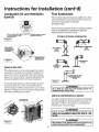
Instructions for Installation (cont'd)
Water Piping
AWARNING
• Look at the top cover of the water heater. The water outlet
is marked hot. Put two or three turns of teflon tape around
the threaded end of the threaded-to-sweat
coupling and
around both ends of the 3/, ,, threaded nipple. Using flexible
HOTTER WATER CAN SCALD: Water heaters are
intended to produce hot water. Water heated to a
!temperature which will satisfy clothes washing, dish
washing, and other sanitizing needs can scald and
permanently injure you upon contact. Some people
are more likely to be permanently injured by hot
water than others. These include the elderly, children,
the infirm, or physically/mentally
handicapped. If
anyone using hot water in your home fits into one of
these, groups or if there is a local code or state law
requiring a certain temperature water at the hot
water tap, then you must take special precautions. In
addition to using the lowest possible temperature
setting that satisfies your hot water needs, a means
such as a mixing valve, should be used at the hot
water taps used by these people or at the water
heater. Mixing valves are available at plumbing supply or hardware stores. Follow manufacturers instructions for installation
of the valves. Before changing
the factory setting on the thermostat,
read the
"Temperature Regulation" section in this manual.
connectors, connect the hot water pipe to the hot water
outlet on the water heater.
• Look at the top cover of the water heater. The cold water
inlet is marked cold. Put two or three turns of teflon tape
around the threaded end of the threaded-to-sweat coupling
and around both ends of the 3//, threaded nipple. Using flexible connectors, comlect the cold water pipe to the cold water
inJ.etof the water heater.
NOTE: This water heater is insulated to minJntiz¢hcat loss
from the tank. Further reduction in heat loss can be aceompfishedbyinsulatlngthehotwaterlinesfromthewaterhcater.
THREADED
TO
SWEATCOUPLINGS
if a water heater is installed in a closed water supply system;
meter with a check valve, etc.., in the cold water supply;
means shall be provided to control thermal expansion.
Contact
the having
local utl/ity
or call Maytag
Service
such as one
a back-t']ow
preventer,Customer
check valve,
water
Center at 1-800-788-8899
for an authorized installer on how
/_
SHUT-OFF
VALVE
___._
riOTOUTLET
TO
to control this situation.
NOTE:
_
HOUSE
_
_[_
COLDINLET
[ _
WATERLINE
To protect against untimely corrosion of hot and
cold water fittings, it is strongly recommended that dl-electric unions or couplings be installed on this water heater
when connected to copper pipe.
3/4" THREADED
NIPPLE
The illustration shows the attachment of the water piping to
the water heater. The water heater is equipped with 3/, inch
water connections.
_
[
NOTE: If using copper tubing, solder tubing to an adapter
before attaching the adapter to the cold water inlet connection.
Do Rot solder the cold water supply line direcdy to the cold
_
__[
_11
TEMPERATURERELIEF
/PRESSURE
/[
|
"_"-'1"/ /
_
water inlet. It will harm the dip robe and damage the tank.
/
"i_/4 " THREADED
NIPPLE
VALVE
PIPE
(Do not cap
DISCHARGE
orplug)
FLOORDRAIN
3O
Instructions for Installation (cont'd)
Temperature-Pressure
Relief Valve
AWARNING
At the time of manufacture this water heater was provided with a combination temperature-pressuresrelief valve
certified by a nationally recognizedtesting laboratory that
maintains periodic inspection of production of listed
equipment or materials, as meeting the requirements for
Relief Valves and Automatic Gas Shutoff Devices for Hot
Water Supply Systems, and the current edition of ANSI
z21.22 and the code requirements of ASME. If replaced,
the valve must meet the requirements of local codes, but
not less than a combination temperature and pressure
relief valve certified as meeting the requirements for
Relief Valves and Automatic Gas Shutoff Devicesfor Hot
Water Supply Systems,ANSI Z21.22 by a nationally recog, t
nized testing laboratory that maintains periodic inspection
of productionof listed equipment or materials.
The valve must be marked with a maximum set pressure
not to exceedthe marked hydrostaticworking pressureof !
&WARNING
The temperature-pressure relief valve must be manually operated at least once a year. Caution should be
taken to ensure that (1) no one is in front of or
around the outlet of the temperature-pressure relief
valve discharge line, and (2) the water manually discharged will not cause any bodily injury or property
damage because the water may be extremely hot.
If after manually operating the valve, it fails to completely reset and continues to release water, immediately close the cold water inlet to the water heater,
follow the draining instructions, and replace the
temperature-pressure relief valve with a new one.
_/_l
not lessthan the water heater input rate as shown on the
model rating plate, (Electric heaters - watts divided by,
1000 x 3415 equal BTU/Hr.rate.)
Your local jurisdictional authority, while mandating the
useof a temperature-pressurerelief valve complying with
ANSI Z21.22 and ASME, may require a valve model different from the one furnished with the water heater.
the water heater (150 Ibs./sq. in.) and a dischargecapacity
Compliancewith suchlocalrequirements must be satisfied
by the installer or end user of the water heater with a
locally prescribed temperature-pressure relief valve
installed in the designated opening in the water heater in
placeof the factory furnished valve.
For safe operation of the water heater, the relief valve
must not be removed from it's designated opening or
plugged.
The temperature-pressure relief valve must be installed
directly into the fitting of the water heater designatedfor
the relief valve. Positionthe valve downward and provide
tubing so that any discharge will exit only within 6 inches
above, or at any distance below the structural floor. Re
certain that no contact is made with any live electrical
part. The discharge opening must not be blocked or
reduced in size under any circumstances.Excessivelength,
over 30 feet, or use of more than four elbows can cause
restrictionand reducethe dischargecapacity of the valve.
/
_l_J
I
I
SHUTOFFvALVE
(/_
,[
COLD
_
__
-TEMPERATUREPRESSURE
RELIEF
VALVE
L
- DISCHARGE
PIPE
(Donot capor plug]
__
No valve or other obstructionisto be placed between the
I dischargedrain
unlessa
6" air
is provided.
Tothe
prevent
bodily injury, hazard
to life,
or gap
property
damage,
relief
relief valve
the tank.to
Dodischarge
not connect
tubing
directly to
valve
mustand
be allowed
water
in quantities
_
FLOOR_RA_----------J_IN
should circumstancesdemand. If the dischargepipe is not
connected to a drain or other suitable means, the water
flow may causeproperty damage.
The DischargePipe:
Must not be smaller in size than the outlet pipe size of
the valve, or have any reducing couplings or other
restrictions.
Must not be plugc_edor blocked,
Must be of material listed for hot water distribution.
Must be installed so as to allow complete drainage of I
both the temperature-pressurerelief valve, and the dis- I
chargepipe.
I
Must terminate at an adequate drain.
Must not have any valve between the relief valve and [
tank,
_[_
[
I
I
RELIEF
VALVE
6 AIRGAP
_-_
OPENING
"THIS
WATER
HEATER
ISAPPROVED
WITHACOMBINATION
TEMPERATUREPRESSURE
RELIEF
VALVE.
FOR
SAFE
OPERATION
OFTHE
WATER
HEATER,
THE
RELIEF
VALVE(S)
MUST
NOT
BEREMOVED
FROMITS
DESIGNATED
POINT
OFINSTALLATION
ORPLUGGED."
YOURLOCAL
JURISDICTIONAL
AUTHORITY,
WHILE
MANDATING
THEUSE
OFATEMPERATURE-PRESSURE
RELIEF
VALVE
COMPLYING
WITHANSI
z21.22ANDASME,
MAYREQUIRE
AVALVE
MODEL
DIFFERENT
FROM
THE
ONE
FURNISHED
WITHTHEWATER
HEATER.
COMPLIANCE
WITHSUCH
LOCAL
REQUIREMENTS
MUSTBESATISFIED
BY
THEINSTALLER
ORENDUSER
OFTHEWATER
HEATER
WITHA LOCALLY
PRESCRIBED
TEMPERATURE-PRESSURE
RELIEF
VALVE
INSTALLED
iN THE
DESIGNATED
OPENING
INTHEWATER
HEATER.
MANUAL
HEADING
- "TEMPERATURE-PRESSURE
RELIEF
VALVES"
FOR
i SEE
INSTALLATION
ANDMAINTENANCE
OFRELIEF
VALVE,
DISCHARGE
LINE
ANDOTHER
SAFETY
PRECAUTIONS.
(
I
31
Instructions for Installation (cont'd)
Filling the Water Heater
A CAUTION
Never use this water heater unless it is completely
filled with water. Toprevent damage to the tank, [
the tank must be filledwith water. Water must flow
from the hot water faucet before turning "ON" gas
to the water heater,
There must be:
• A readily accessiblemanual shut offvalve in the gas supply
line serving the water heater, and
• A drip leg (sediment trap) ahead of the gas control valve to
help prevent dirt and foreign materials from entering the gas
control valve.
• A flexible gas connector or a ground joint union between the
To fill the water heater with water:
•
shutoffvalve and control valve to permit servicing of the unit.
Close the water heater drain valve by turning the handle to
the right (clockwise). The drain valve is on the lower front
of the water heater,
Be sure to check all the gas piping for leaks before lighting the
water heater. Use a soapy water solution, not a match or open
•
Open the cold water supply valve to the water heater,
NOTE: The cold water supply valve must be left open
when the water heater is in use.
flame. Rinse off soapy solution and wipe dry.
•
To insure complete ftUing of the tank, aUow air to exit by
opening the nearest hot water faucet. Allow water to run
until a constant flow is obtained. This will let air out of the
sea level.
water heater and the piping.
5,500 feet above sea level.
•
Check all new water piping for leaks. Repair as needed.
G
as Pip ing
If a standard model is installed above 3,300 feet or a high altitude model is installed above 5,500 feet, the input rating must
be reduced at the rate of 4 percent for each 1,000 feet above sea
Standard Models are for installation up to 3,300 feet above
High Altltude Models are for installation from 3,300 to
leva which requires replacement of the burner orifice in accordance with the National Fuel Gas Code ANSI Z223.1 / NF'PA
AWARNING
54. Contact your bcal gas utility for further information.
Make sure the gas supplied is the same type listed
on the model rating plate, The inlet gas pressure
must not exceed 10.5 in. water column (2.6kPa) for
natural gas or 13 in. water column (3,2kPa) for
propane (L.R) gas, The minimum inlet gas pressure
listed on the model rating plate is for the purpose
of input adjustment,
AWARNING
Failure to replace the orifice could result in improper
and inefficient operation of the appliance, producing carbon monoxide gas in excess of safe limits,
which could result in serious injury or death.
Contact your gas supplier for any specific changes
which may be required in your area.
I
AWARNING
AWARNING
exceeding
If thegas control
½ poundvalve
per square
is subjected
inch (3.5kPa),
to pressures
the
damage to the gas control valve could result in a
fire or explos on from eak ng gas.
J
The appliance and its gas connection must be leak I
testedbefore placing the appliance in operation.
I
AWARNING
If the maingas line shutoff serving all gas appliances is used, also turn nOFF" the gas at each appliance. Leave all gas appliances shut off until the
AWARNING
The appliance and its individual shutoff valve must i
be disconnected from the gas supply piping system I
water heater nstallat on is compete,
test
pressures
in excess
of ½ pound
during
any pressure
testing
of the per
gassquare
systeminch
at
(3.5kPa).
The appliance must be isolated from the gas supply piping system by closing its individual manual
shutoff valve during any pressure testing of the
gas suppl_, piping system at test pressures equal or
less than ½ pound per square inch (:L5kPa).
A gas line ofsttffident size must be run to the water heater,
Consttlt the current edition of National Fuel Gas Code ANSI
Z223.1, also referred to as NFPA 54 and the gas company
concerning pipe size.
32
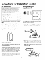
Instructions for Installation (cont'd)
AWARNING
I
GAS PIPING
Use pipe joint compound or teflon tape marked as '
being resistant to the action of petroleum [Propane
(LR)]gases.
I
SEDIMENT
FLEXIBLE
heater
CONNECTOR
GAS SI. PPLY PIPING
TRAP
MANUAL
SHUTOFF
A sediment trap shall be installed as close to the inlet of the
water
WITH
as practical
at the
time
of water
heater
_ _
VALVE
instaUa-
tion. The sediment trap shall be either a tee fitting with a
capped nipple in the bottom outlet or other device recognized
as an effective sediment trap. Ifa tee fitting is used, it shall be
installed in conformance with one of the methods of installation shown below.
Connecting
the gas piping
water
can be accomplished
ods
heater
to the gas control
by either
valve
of the
--t...
FLEXIBLE
GASCONNECTOR
LABELED
ASCOMPLYING
WITHANSISTANDARDS
GROUNDJOINT
UNION
(OPTIONAL)
of the
two meth-
shown.
_
/
DRIPLEG
(SEDIMENT
TRAP/
3 _ MIN.
GAS
VALVE
CONTROL
CAP
_,WARNING
Contaminants in the gas lines may cause improper
operation of the gas control valve that may result
in fire or explosion. Before attaching the gas line
be sure that all gas pipe is clean on the inside. To
trap any dirt or foreign material in the gas supply
line, a drip leg (sometimes called a sediment trap)
must be incurs.orated in the piping. The drip leg
must be readily accessible. Install in accordance
with the "Gas Piping" section. Refer to the current
edition of the National Fuel Gas Code, ANSI Z223.1
also referred to as NFPA 54.
GAS PIPING
WITH
ALL BLACK IRON
PIPE
GAS CONTROL
GASSUPPLY
PIPING
SHUTOFF
VALVE
MANUAL
_
GROUND JOINT_
UN,ON
_ .I
3" MIN
33
I
_:R
BLACK PIPE
I (SEDIMENT
I I TRAP)
--
GAS
TO
Instructions for Installation (cont'd)
Installation
Checklist
BEFORE LIGHTING THE PILOT:
CHECK FOR LEAKS
Check the gas lines for Ieaks.
Be sure to check all your gas pipes for leaks before lighting
a. Use a soapy water solution.
using a match
DO NOT
test for gas leaks
c. Check for bubbling
on all gas pipes, joints
Turn "OFF" gas and make the necessary
d. Recheck
for leaks,
e.
Rinse offsoapy
soiution and wipe dry.
"Temperature-Pressure
•
soapy water solution
repairs.
not a match or
after pilot is lit and
for this, too.
_
_
(
\
relief valve properly
and piped to an adequate
solution,
the factory gas fittings
gas control knob is still in "PILOT"
position. Then, check
the fittings when the main burner is turned "ON". Use a
soap. This means you have a leak.
Is the new temperature-pressure
Use a soapy water
open flame. Check
b. Brush the soapy water solution
and fittings,
installed
your water heater.
or open flame,
f_
l/'J
-4-
SHUTOFF
VALVE
-,t---HOT
COLD
drain? See
Relief Valve" section.
Are the cold and hot water lines connected
heater correctly? See "Water
Instruetmns
for Installatmn
to the water
Piping" instructions
sectmn.
in the
GAS
SUPPLY
•
Is the water heater completely filled with water? See
"Filling" instructions
in the "Instructions
for Installation"
section.
•
Will a water leak damage
New Water Heater"
Is there proper
anything
anything?
See the "Locating
DISCHARGEPiPE
the
section.
clearance
between
the water heater and
the New
TEE
DRiPLEG'--_IJ
(Sediment
J[
section.
Do you have adequate
ventilation
trap)
so that the water heater
will operate properly? See "Combustion Air and Ventilation"
m the Instructxons for Installation
sectaon.
Is the draft hood vent piping properly
"Venting"
instructions
[Do not cap or plug)
_
that might catch fire? See the "Locating
water Heater"
TEMPERATUREPRESSURE
RELIEFVALVE
secured?
in the "Instructions
tD
PiPE
CAP
;" AIR GAP
See
for Installation"
_POTABLE)
sectioIFl.
HEATING
ONLY
_COELN_C_E_R
Is there proper
clearance
between
thing that might catch on fire? See "Venting"
in the "Instructions
for Installation"
CJ&pAOTY
the vent pipe and any-
]us
instructions
_o
section.
c_s
Is the vent pipe properly sloped and does the vent termi .......................
hate outdoors? See ........
Venting
mstmctaons m the
Instructions
for Installation
sectmn.
Do yon need to call your gas company
_
ot.t
,_
I um._,a
[
ea_.a_R
J
_,,_,
I
'_
]
]
.o
_
AUTOMATIC
STORAGE
WATER
H
EATER
FOR DIRECT VENT fNSTALLATION
J
_
to check the gas
pipe and its hookup?
M,_
I
isaTrademark
ofMay_ag
Ca_po_a6o_
_ecl
is used u_der License to State Industries, ]ne
MODEL
34
RATING PLATE
i
Instructions for Operation
AWARNING
BEFORE LIGHTING [PROPANE (L.P.) GAS WATER
HEATERS]: Propane (L.P.) gas is heavier than air.
Should there be a leak in the system, the gas will
settle near the ground. Basements, crawl spaces,
skirted areas under manufactured (mobile) homes
(even when ventilated),
closets and areas below
for the accumulato light or relight
the water heater's pilot or turning on a nearby electrical light switch, be absolutely sure there is no
accumulated gas in the area. Search for odor of gas
by sniffing at ground level in the vicinity of the
appliance. If odor is detected, follow steps indicated
at "For Your Safety" on the cover page of this man-
/Figure 10_
ground level will serve as pockets
Lighting
tion of this gas. Before attempting
[
J
,_
ual then leave the premises.
Lighting and operating instructions are located on front of
the water heater, above or to one side of the gas control valve.
_
i
Figure 1 1
I
I
AN ODORANT IS ADDED TO THE GAS USED
BY THIS
AWARNING
WATER HEATER.
FOR YOUR SAFETY
IF YOU SMELL GAS:
Do not try to light any appliance.
Do not touch any electrical switch; do not use any
phone in your building.
Immediately call your gas supplier from a neighbor's
If
youphone.
cannotFollow
reach the
your
gas
gas
supplier's
supplier,instructions.
call the fire
department.
G
[Figure 12]
DO NOT force the gas control knob. Use only your
OBSERVATION
. WAN,NG
to "ON", "OFF" or "PILOT". Never use a tool such as
hand to push it down to light the pilot, or to turn it
PORT_
n
It
PIEZO
_
_
knob. A damaged knob may result in an explosion
and serious injury. If you have problem turning the
knob, call the gas supplier immediately.
alever, wrench or pliers. Do not hit or damage the
Figure 13
35
__
IFi,ure
14I
t
IGNITOR
Instructions for Operation (cont'd)
Lighting
label on the water
heater as it appears above the thermostat
FOR YOUR SAFETY READ BEFORE LIGHTING
If you do not follow these instructions exactly, a fire or explosion
may resultcausing propertydamage,
WARNING personal injury or loss of life. I
A. Thisappliancehasa pilotwhichmustbe lightedby
hand.Whenlighting
thepilot,followtheseinstructions
exactly.
B.BEFORE
LiGHTiNG
smellallaroundtheappliance
area
for gas.Besureto smellnextto thefloorbecause
somegasisheavier
thanairandwillsettleonthefloor,
WHATTODOIFYOUSMELLGAS
• Donottrytolightanyappliance.
• Do nottouchanyelectricswitch;do notuseany
phoneinyourbuilding,
• Immediately
callyourgassupplierfroma neighbor's
phone.Followthegassupplier's
instructions,
LIGHTING
• If youcannotreachyourgassupplier,callthefir
department.
C.Useonlyyourhandtopushin orturnthegascontrol
knob.Neverusetools.Iftheknobwillnotpushin or
turnbyhand,don'ttryto repairit, calla qualified
servicetechnician.
Forceor attempted
repairmayresult
inafireorexplosion.
D.Donotusethisappliance
if anyparthasbeenunder
water.Immediately
calla qualified
servicetechnician
toinspect
theappliance
andto replace
anypartofthe
controlsystemandanygascontrolwhichhasbeen
underwater.
INSTRUCTIONS
1. STOP!Readthesa;_r information
aboveonthislabel.
7. Depressthe gas controlknoball the waydown.
2. Setthethermostat
tolowest
setting.L_y
turning
thewater
Immediately
depress
thepiezoignitor
buttonuntila click
temperaturedialclockwise,( f
_, ) to its lowest
is heardandthenrelease.Checkto seeif pilotis lit
temperature
setting(withan'owondial)asshown.DO
through
the observation
port.ifpilotisnotlit,continue
NOTFORCE. L_,_
todepress
andreleasepiezoignitorbuttonuptosix(6)
times.If pilotis stillnotlit, repeatsteps3 through7.
Afterthepilotislit,continue
toholdcontrolknobdown
for aboutone(1)minute,Releaseknobanditwillpop
.._.
backup.Pilotshouldremainlit. If it goesoutrepeat
3. Turngascontrolknobclockwise
to "OFF" posJsteps2 through
7.
tion.Knobcannotbeturnedfrom"PILOT"to "OFF"
• If knobdoesnotpopupwhenreleased,
stopand
unlessknobis depressed
slightly.DO NOT FORCE.
immediately
callyourservicetechnician
orgassup(Figure10,page35)
plier.
4. Waitfive(5)minutes
toclearoutanygas.Ifyouthensmell
• If the pilotwill notstay lit after severaltries,
gas,STOP!Folfow"B"in thesafetyinformation
aboveon
depressandturnthegascontrolknobclockwise
thislabel.Ifyoudon'tsmellgas,gotothenextstep.
@ J to"OFF"andcallyourservicetechnician
or
5. Ifyoudon'tsmellgas,turnknobongascontrolcounter
gassupplier.
(Figure10,page35)
clockwise_@to"PILOT"peaition.(Figure
11,page35) 8. At armslengthaway,turngascontrolknobcounter6. Pilotcanbeviewed
through
observation
pert.NoteIocaclockwise
_@to thefull "ON"position.
WARNING
tionofpiezoignitor.
(Figure13,pa e35)
Donotusegascontrolknobto regulategasflow.
OBSERVATION
PORT
PIEZO
IGNITOR
9. Atarmslengthaway,setthethermostat
todesiredsetting.Themark(A) indicative
of approximate
120°Fis
preferred
startingpoint,Somelocallawsmayrequirea
lowerstartingpoint.If hotterwateris desired,see
instruction
manual
and"waming"below.
(Figure12,page35)
Beforechangingtemperaturesettingseeinstructionmanual.
Hotterwaterincreasestheriskof scaldinjury.WARNING
TO TURN OFF GAS TO APPLIANCE
1. Set the thermostat to lowestsetting bv turning
the watertemperature
dialclockwise
( ,I"- _) to its
lowesttemperaturesetting(witharrowon dial)as
shown.DONOTFORCE.
36
2. Turngascontrolknobclockwise_)
to "OFF"
position.Knobcannotbeturnedfrom"PILOT"to
"OFF"unlessknobis depressed
slightly.DO NOT
FORCE.(Figure10,page35)
Instructions for Operation (cont'd)
Temperature
Regulation
Due to the nature of the typical gas water heater, the water
temperature in certain situations may vary up to 30°F higher or
Turn the water temperature dial clockwise (_-"%) to
decrease the temperature, or counterclockwise (("_)
to
lower at the point of use such as, bathtubs, showers, sink, etc.
increase the temperature.
J]-[1
This means that when the temperature adjustment dial is set
ture at any hot water tap could be as high as 150°F or as low
at
mark approximating 120 ° F, the actual water temperaas the
90°F.
F-GAS CONTROL
KNOB
_
o
Any water heater's intended purpose is to heat water. Hot
water will present a scald hazard. Depending on the time element, and the people involved (normal adults, children, toddlers, elderly, infirm, etc.) scalding may occur at different
E
water
temperatures.
is oeeded for cleaning (bodies, dishes, clothing). Hot
i
_
_¢_'_'W_
WATER
TEMPERATURE
_ADJUSTWG DIAL)
&WARNING
HOTTER WATER CAN SCALD: Water heaters are
intended to produce hot water• Water heated to a
temperature which will satisfy clothes washing, dish
washing, and other sanitizing needs can scald and
PILOT LIGHTING-
i permanently
injure
upon contact.injured
Some by
people
are more likely
to you
be permanently
hot
water than others. These include the elderly, children,
the infirm, or physically/mentally
handicapped If l
anyone usmg hot water m your home fits mto one of
I these groups or if then is a local code or state law]
requiring a certain temperature water at the hot I
water tap, then you must take special precautions. In
addition to using the lowest possible temperature
se_ing that satisfies your hot water needs, a means
such as a mixing valve, should be used at the hot
water taps used by these people or at the water
heater. Mixing valves are available at plumbing supply or hardware stores. Follow manufacturers instructions for installation of the valves. Before changing
the factory setting on the thermostat,
read the
Temperature
VERY HOT=
C=
B=
A =
Set here before attempting to light
pilot.
Setting
approx. 160°F
approx• 150°F
approx• 140°F
approx. 130°F
• = approx. 120°F
LOW-- approx. 80°F
Time
to Produce
2nd &
3rd Degree
Barnson
Adult Skin
About 1/2 second
About 1-1/2 seconds
Less than 5 seconds
About 30 seconds
More than 5 minutes
..........
NOTE: Water temperature range of 1200-140"F (49°-60°C)
recommendedbymost
dishwasher manufacturers.
I "Temperature Regulation" section in this manual.
_WARNING
turn
"OFF"the
manualgascontrel
valveto
the appliance.
Should
overheating
occuror the gas
supplyfail
to shut off
&WARNING
Never allow small children to use a hot water tap,
or to draw their own bath water• Never leave a
child or handicapped person unattended in a bath- I
tub or shower.
I
The thermostat of this water heater has been factory set at its
lowest position, to reduce the risk of scald injury. It is
adjustable and must be reset to the desired temperature setting. The mark (•) indicative of approximately 120°F is the
preferred starting point. Some states have a requirement for a
lower setting. If you need hotter water, follow directions for
temperature adjustment, but beware of the warnings in this
section.
37
Service and Maintenance
Venting
System Inspection
Burner Inspection
AWARNING
At least once a year a visual inspection should be made of the
venting system.You should look for:
Flood damage to a water heater may not be readily
visible or immediately detectible. However, over a
• Obstructions which could cause improper venting. The
combustion and exhaust air flow must not be obstructed.
period
of time
a flooded
heaterDEATH,
w II create
dangerous
conditions
whichwater
can cause
SERI-I
OUS BODILY INJURY, OR PROPERTY DAMAGE.
Contact the Maytag dealer from whom the appli-
• Damage or deterioration which could cause improper vent-
ance
was purchased or
Customer
Service
at 1-800-788-8899
for call
an Maytag
authorized
servicer
to '
replace a flooded water heater. Do not attempt to
repair the unit! It must be replaced!
ing or leakage of combustion products,
• Rusted flakes around top of water heater.
At least once a year a visual inspection should be made of the
A WARNING
main burner and pilot burner. The drawing is for your reference.
Chemical vapor corrosion of the flue and vent system may occur if air for combustion contains certain
chemical vapors. Spray can propellants, cleaning solvents, refrigerator and air conditioner refrigerants,
swimming pool chemicals, calcium and sodium chloride, waxes, bleach, and process chemicals are typi-
You should check for sooting which is not normal and wiLt
impair proper combustion.
cal compounds which are potentially corrosive,
Obstructed or deteriorated vent systems may present a serious health
AWARNING
risk or asphyxtation.
I
\7/S/%
AWARNING
Soot build-up indicates a problem that requires cor-
AWARNING
heater before
rection
and leave
further
UOFF"
use. until
Turn "OFF"
repairsgas
are
to made,
water
because failure to correct the cause of the sooting
can result in a fire or explosion causing DEATH,
SERIOUS BODILY INJURY, OR PROPERTY DAMAGE.
Be sure the vent piping is properly connected to
prevent escape of dangerous flue gasses which
could cause deadly asphyxiation.
Burner Cleaning
AWARNING
If after inspection of the vent system you found
sooting or deterioration,
something is wrong. Call
the local gas utility or Maytag Customer Service at
1-800-788-8899 for an authorized servicer to correct
the problem and clean or replace the flue and ventinc_ before resuming operation of the water heater,
fadure to make corrections
can result in a fire, or
explosion causing DEATH, SERIOUS BODILY INJURY,
)R PROPERTY DAMAGE.
In the event your burner needs cleaning, use the following
instructions:
If inspection of the burner shows that cleaning is required,
turn the gas control knob clockwise (f'_)
to the "OFF"
position, depressing slightly.
NOTE:
The knob cannot be turned from "PILOT" to
"OFF" unless knob is depressed slightly. DO NOT
FORCE.
Loose deposits on or around the burner can be removed by
carefully using the hose of a vacuum cleaner inserted through
the access door of the water heater. If the burner needs to be
removed for additional cleaning, call Maytag Customer
Service at 1-800-788-8899 for an authorized servicer to
remove and clean the burner and correct the problem that
required the burner to be cleaned,
38
Serviceand Maintenance (cont'd)
L.R Gas Control Valve & Burner
Assembly Replacement
Draining
The water heater should be drained if being shut down during
Information
freezing temperatures. Also periodic draining and cleaning of
AWARNING
sediment from the tank may be necessary.
PROPANE (L.P.)
GAS CONTROL
VALVE AN BURNER
ASSEMBLY
REPLACEMENT
INFORMATION.
• Turn tl_e gas control knob to the "OFF" position.
For Propane (L.R) Gas Models Only:
Your water heater is equipped with a Propane (L.R)
gas control valve and a main burner assembly with
left hand threads for the following fittings and their
connections,
• CLOSE the cold water inlet valve to the water heater.
• OPEN a nearby hot water faucet and leave open to allow
for draining.
• Connect a hose to the drain valve and terminate to an ade-
• The connection between the manifold and the gas control
valve (A to B) are left hand threads,
quate drain.
• OPEN the water heater drain valve to allow for tank
• The connection between the main burner orifice and the manifold (C to D) are left hand threads,
draining.
NOTE: If the water heater is going to be shut down and
For ordering these replacement parts, please refer to the "Repair
Parts List" section of this manual
drained for an extended period, the drain valve should be
left open with hose connected allowing water to terminate
to an adequate drain.
• Close the drain valve.
section.
• Follow the fighting instructions in the "Lighting" section to
" Follow instructions in the "Filling The Water Heater"
restart the water heater.
__
B
_
Anode
Rod Inspection
The rod must be maintained to keep the tank in operating
not necessarily water condition. It may be necessary to have
the anode rod inspected a few times during the first year to
see what effect the water has had. A corroded or pitted anode
condition. Anode deterioration depends on water conductivity,
rod, in the first year, indicates high water conductivity and
should be checked and or replaced more often than an anode
rod that appears to be fairly clean. Inspection should be conducted by a qualified technician.
39
Service and Maintenance (cont'd)
Temperature-Pressure Relief
Valve Operation
Drain Valve Washer
Replacement
The temperature-pressure
ated at least once a year.
NOTE: For replacement, use a W_"x Wd'x ½" thick washer
available at your nearest hardwa_ store. For ordering
replacement washers, refer to the "Repair Parts List" section.
rellef valve must be manually oper-
TEMPERATURE-PRESSURE
1. Turn "OFF" gassupply to water heater.
3. Turning counter clockwise, remove the hex cap below the
screw handle,
4. Remove the washer and put the new one in place.
2. Follow
"Draining"
instructions.
5.
Screw the
handle and
cap assembly back into the drain
valve and retighten using a wrench. DO NOT OVER
TIGHTEN.
DISCHARGE
PIPE
6. Follow instructions in the "Filling The Water Heater"
section.
7. Check for leaks.
Failure to instal/and maintain a new properly listed temperature-pressure refiefvalve _
release the manufacturer from
any claim which might result from excessive temperature or
8. Follow the lighting instructions in the "Instructions for
Operation" section to restart the water heater.
pressure.
AWARNING relief valve on the
f the temperature-pressure
appliance weeps or discharges periodically, this
_ay be due to thermal expansion.
Your water
aeater may have a check valve installed in the
water line or a water meter with a check valve. Call;
Maytag Customer Service at 1-800-788-8899 for an
authorized servicer for further information. Do not
plug the temperature-pressure relief valve.
t_
_"
HANDLEAND
CAPASSEMBLY
WASHER
Housekeeping
AWARNING
When checking the temperature-pressure
relief
valve operation, make sure that (1) no one is in front i
of or around the outlet of the temperature-pressure I
relief valve discharge line, and (2) that the water
manually discharged will not cause any property
damage because the water may be extremely hot.
Vacuum around base of water heater for dust, dirt, and llnt on
a regular basis.
If after manually operating the valve, it fails to completely reset and continues to release water, immediately close the cold water inlet to the water heater,
follow the draining instructions, and replace the
temperature-pressure relief valve with a new one.
To insure sufficient ventilation and combustion air supply,
proper clearances from the water heater must be maintained
Combustible materials such as clothing, cleaning materials, or
flammable liquids, etc. must not be placed against or adjacent
to the water heater.
at all times.
Service
Before calling for repair service, read the Start Up Conditions
and Operational Conditions found in the Troubleshooting
Guide of this manual.
If a condition persists or you are uncertain about the operation of the water heater, let a qualified person check it out.
Call Maytag Customer Service at 1-800-788-8899
authorized servicer.
4O
for an
Troubleshooting
Start Up Conditions
CONDENSATION
THERMAL
Whenever the water heater is ftUedwith cold water, a certain
amount of condensation will form while the burner is on. A
water heater may appear to be leaking when in fact the water
is condensation. This usually happens when:
When a new water heater is filled with cold water for
the first time.
Water supply systems may, because of high fine pressure, frequent cut-offs, the effects of water hammer and others, have
installed devices such as pressure reducing valves, check
valves, back flow preventers, etc. to control these types of
problems. When these devices are not equipped with an internal by-pass, and no other measures are taken, the devices
cause the water system to be closed. As water is heated, it
• When gas burns and water vapor is produced in water
heaters, particularly high efficiency models where flue
expands (thermal expansion) and closed systems do not allow
for the expansion of heated water.
-
temperatures are lower.
EXPANSION
The water within the water heater tank expands as it is heated
• When you use large amounts of hot water in a short
and increases the pressure of the water system. If the relieving
time and the refRl water is very cold.
point of the water heater's temperature-pressure relief valve is
reached, the valve will refieve the excess pressure. The tern-
Moisture from the products of combustion condense on the
cooler tank surfaces and form drops of water which may fail
perature-pressure relief valve is not intended for the constunt relief of thermal expansion. This is an unacceptable
onto the burner or other hot surfaces to produce a "sizzling" or
"frying" noise.
condition and must be corrected.
Excessive condensation can cause pilot outage due to water
running down the flue tube onto the main burner and putting
out the pilot,
a closed system have a by-pass and/or the system have an
expansion tank to relieve the pressure built by thermal expansion in the water system. Expansion tanks are available for
ordering through Maytag Customer Service (1-800-788-8899).
Contact the local plumbing inspector, water supplier, and/or
call Maytag Customer Service at 1-800-788-8899 for an
authorized servicer for assistance in controlling these situafons.
It is recommended that any devices installed which could create
Because of the suddenness and amount of water, condensation
water may be diagnosed as a "tank leak". After the water in
the tank warms up (about 1-2 hours), the condition should
disappear.
Do not assume the water heater is leaking until there has been
enough time for the water in the tank to warm up.
STRANGE
An undersized water heater will cause more condensation.
Possible noises due to expansion and contraction of some
The water heater must be sized properly to meet the family's
demands for hot water including dishwashers, washing
metal parts during periods of heat-up and cool-down do not
represent harmful or dangerous conditions.
machines and shower heads.
Condensation
Excessive condensation may be noticed during the winter and
early spring months when incoming water temperatures are at
their lowest.
area during heating and cooling periods and should be considered normal. See "Condensation" section.
Good venting is essential for a gas fired water heater to oper_
ate properly as well as to carry away products of combustion
and water vapor.
SMOKE/ODOR
][tis not uncommon to experience a small amount of smoke
and odor during the initial start-up. This is due to burning off
of oil from metal parts, and will disappear in a short while.
41
SOUNDS
causes sizzling and popping with the burner
Troubleshooting (cont'd)
Operational
Conditions
SMELLY WATER
HIGH TEMPERATURE SHUT OFF SYSTEM
In each glasslined water heater there is installed at least one
anode rod (see parts section) for corrosion protection of the
tank. Certain water conditions will cause a reaction between
This water heater is equipped with an automatic gas shut off
system. The high temperature shut offis built into the gas
control valve. This system shuts offthe gas supply to the
this rod and the water. The most common complaint associated with the anode rod is one of a "rotten egg smell". This
odor is derived from hydrogen sulfide gas dissolved in the
water. The smell is the result of four factors which must all be
present for the odor to develop:
water heater burners when high water temperatures are present. It is non-msettable. If the high temperature shut off
activates, the gas control valve must be replaced. If this were
to occur, turn "OFF" the entire gas supply to the water heater.
Call Maytag Customer Service at 1-800-788-8899 for an
authorized servicer.
a. a concentration of suffate in the supply water.
b. little or no dissolved oxygen in the water.
&WARNING
c. a sulfate reducing bacteria within the water heater.
(This harmless bacteria is non-toxic to humans.)
I
Should overheating
occur or the gas supply fail to I
off, turn "OFF" the manual gas control valve to I
I shut
[the appliance.
d. an excess of active hydrogen in the tank. This is caused
by the corrosion protective action of the anode.
]
NOT ENOUGH OR NO HOT WATER
Smelly water may be eliminated or reduced in some water
heater models by replacing the anode(s) with one of less active
material, and then chlorinating the water heater tank and all
1. Check the manual gas shut offvalve to be sure it is open.
hot water lines. Call Maytag Customer Service at 1-800-7888899 for an authorized servicer for further information concerning an Anode Replacement Kit #66001068 and this
Chlorination Treatment.
2. Check the pilot flame. It may have gone out. All models
have an opening in the outer door for viewing the pilot.
3. If the pilot is not lit, follow the "Lighting" instructions in this
manual or located above the gas control valve on the water
If the smelly water persists after the anode replacement and
chlorination treatment, we can only suggest that continuous
chlorination and filtering conditioning equipment be considered to eliminate the water problem,
heater to refight the pilot. If the water was extremely hot and
is now cold, the high limit safety temperature shut offmay
have put out the burner and pilot. If the high temperature
shut off activates, the gas control valve must be replaced. Call
Maytag Customer Service at 1-800-788-8899 for an autho-
Do not remove the a_aodeleaving the tank unprotected. By
doing so, all warranty on the water heater tank is voided.
rized servicer.
4. The gas control knob must be turned to the "ON" position.
"AIR"
IN HOT WATER
FAUCETS
5. The temperature adjustment dial may be set too low. See the
"Temperature Regulation" section.
A WARNING
6. The gas company can check the gas input to see if it is correct.
HYDROGEN GAS: Hydrogen gas can be produced in
a hot water system that has not been used for a
long period of time (generally two weeks or more).
Hydrogen gas is extremely flammable and explosive. To prevent the possibility of injury under these
conditions, we recommend the hot water faucet be
opened for several minutes at the kitchen sink
before any electrical appliances which are connected to the hot water system are used (such as a dishwasher or washing machine). If hydrogen gas is present, there will probably be an unusual sound similar to air escaping through the pipe as the hot
water faucet is opened. There must be no smoking
or open flame near the faucet at the time it is open.
An underfired water heater will not heat water as quickly.
7. Look for leaking or open hot water faucets. Make sure all are
closed.
8. The cold water inlet temperature maybe colder during the
winter months. It will take longer to heat the water and
seemlike tesshot water.
9. If you cannot find what is wrong, call Maytag Customer
Service (1-800-788-8899 for an authorized servicer.
42
Troubleshooting (cont'd)
WATER
IS TOO HOT
1. The temperature adjustment dial may be set too high, See the
"Temperature Adjustment" section.
NOTE: A period of time is necessary after an adjustment
has been made for the water temperature m reach the new
temperatu_ setting.
2. If lower temperature settings wil/not lower the water temperature, call Mayt'ag Customer Service (1-800-788-8899) for an
authorized servicer.
AWARNING
Due to the nature of the typical gas water heater,
the water temperature in certain situations may be
hotter than the thermostat setting.
Short, frequent draws of hot water - especially with
very coldincoming water - can shock the thermostat into brief operation resulting in hotter and hotter layers of water closer to the top of the tank.
Changes in hot water usage patterns or ralsinq the
temperature differential between the cut-on of the
thermostat and the cold water temperature
will
usually eliminate the problem.
43
Troubleshooting (cont'd)
Leakage Checkpoints
Use this guide to check a "Leaking" water heater. Many suspected "Leakers" are not leaking tanks. Often the source of
IRead this manual _efore
checking the |
]water heater make sure the gas supply hasbeen]
I turned "OFF", and never turn the gas "ON" before
the water can be found and corrected.
[ the tank is completely
If you are not thoroughly familiar with your local gas codes
your water heater, and safety practices, contact your local gas
utility or call Maytag Customer Service at 1-800-788-8899
for an authorized servicer to check the water heater,
lk CAUTION
Never use this water heater unless
it is completely filled with water. To
prevent damage to the tank, the
tank must be filled with water.
Water must flow from the hot
water faucet before turning "ON"
gas to the water heater.
O
_I
Nil
Ill
II
D_t,
O
_
•
= "
full of water.
water vapor
conthe draft hood is
which has
densed
out of the combustion products. This is caused
by a problem in the vent. Call Maytag Customer Service
Water
at
be
in humid weather
*Condensation may
seen on pipes
or pipe connections may be leaking.
at 1-800-788-8899 for an authorized servicer.
primary
anode
rodtting
maybe
leakiog
lit)
ILl
0
Small amounts of water from temperature-pressure relief
valve may be due to thermal expansion or high water
[11
' "
-_[_
pressure in your area.
* The temperature-pressure
relief valve may be leaking
at
Water from a drain valve may be due to the valve opened
slightly.
[|
m
_
*The drain valve may be leaking at the tank fitting.
_]_
Combustion products contain water vapor which can
condense on the cooler surfaces of the tank. Droplets
form and drip into the fire or run on the floor. This is
common at
startup
the time of
after installation and
when incoming water is cold.
O
Water in the water heater bottom or on the floor may be
from condensation, loose connections, or the relief valve.
|1£
i
Ig-
DO NOT replace the water heater until a full inspection
of all possible water sources is made and necessary corrective steps taken. Leakage from other appliances, water
lines, or ground seepage should also be checked.
•NOTE: To check where threaded portion enters tank, insert cotton swab between jacket opening and £tting. If cotton is wet, follow
"Draining" instructions in the "Service and Maintenance" section and then remove fitting. Put pipe dope or teflon tape on the threads
and replace. Then follow "Filling the Water Heater" instructions in the "Instructions for Installation" section.
44
Notes
45
Repair Parts List
MAYTAG GAS WATER HEATERS MODEL NUMBERS:
HJ640NBDS
HJ640PBDS
40 Gallon Natural Gas
40 Gallon Propane (L.R) Gas
6" I.D.
VENT PIPE
6" O.D. VENT
EXTENSIONPIPE
27
29
37
43
HJ650NBDS
HJ650PBDS
O-RINGGASKET
30
35
41
3_ FLUEPIPE
24
33
39
45
Standard Vent
Kit:
6,,,° I
50 Gallon Natural Gas
50 Gallon Propane (L.R) Gas
3" FLUEEXTENSIONPIPE
31
36
42
ROPEGASKET
25
28
34
40
26
32
38
44
66001422]--_
EXTENSION
/ _
6" O.D. VENT PIPE
_
_:_'_.
46
(_7_
VENTPIPE
(FLARED)
N
ROPE
50
_!11_51
_
50
3" FLUE
J
J
Jj
JJ
O-RING
EXTENS,ON
P,PE
_GASKET
GASKET
GASKETO'R'NG
_ L_J__
L__J.__.
• '66001423
1 - ROPE
Optional Vent Kits: 66001424I
J
66001425
"
GASKET
_.b_
3" FLUE I
(FLARED) 23 _
22 C:_
21
6" O.D. VENT PIPE
EXTENSION
j ...................
"- .-Z----Z_---.....
Each Vent Kit can be used
either horizontally or vertically,
but only one vent kit can be
used horizontally or vertically,
[---_
I
= _
is
c_
l_ _52
46
" " ii
'
_
18
i
i
!I
i
\
Repair Parts List (cont'd)
MAYTAG GAS WATER HEATERS MODEL NUMBERS:
HJ640NBDS
40 Gallon Natural Gas
HJ640PBDS
40 Gallon Propane (L.P.) Gas
HJ650NBDS
HJ650PBDS
50 Gallon Natural Gas
50 Gallon Propane (LR) Gas
Model Number
KEY
NO.
HJ640NBDS
PARTDESCRIPTION
HJ640PBDS
HJ650NBDS
PARTNUMBERS
HJ6SOPBDS
1.
2.
3.
AccessDoor Clips (Pkg. 2)
Right AccessDoor w/Gasket
Left Access Door w/Gasket
66001204
66001205
66001206
66001204
66001205
66001206
66001204
66001205
66001206
66001204
66001205
66001206
4.
Burner Orifice (Nat.)
(Drill Size)
Burner Orifice (Nat.) Hi-Altitude
(Drill Size)
66001025
#33
66001035
#36
--
66001159
V8
66001025
#33
--
4.
--
--
4.
Burner Orifice [Propane (L.R)]
(Drill Size)
--
66001172
#50
--
66001040
#49
4.
-66001391
66001183
66001041
#51
66001391
--
--
5.
6.
Burner Orifice [Propane (LR)] Hi-Altitude
(Drill Size)
Thermocouple
Gas Control Valve (Nat.)
66001391
66001183
66001172
#50
66001391
--
6.
7.
7.
Gas Control Valve [Propane (L.P.)]
Gas Manifold (Nat.)
Gas Manifold [Propane (L.P.)]
-66001037
--
66001004
-66001044
-66001037
--
66001004
-66001044
8.
Pilot Tube w/Fittings
66001188
66001188
66001188
66001188
9.
9.
10.
Burner (Nat.)
Burner (Nat.)
Inner Door
66001027
-66001029
-66001027
66001029
66001027
-66001029
-66001185
66001029
11.
Pilot (Nat.) w/electrode
66001472
--
66001472
--
11.
12.
13.
-66001181
66001021
66001473
66001181
66001021
-66001181
66001021
66001473
66001181
66001021
14.
15.
16.
17.
Pilot [Propane (L.P.)] w/electrode
Drain Valve
Drain Valve Washer*
(_2" x _Yo_"
x W' thick)*
Jacket Clips (Pkg. 8)
Nipple
Temperature-Pressure Relief Valve
Anode Rod
66001242
66001311
66001216
66001157
66001242
66001311
66001216
66001157
66001242
66001311
66001216
66001157
66001242
66001311
66001216
66001157
18.
19.
20.
Nipple
Dip Tube
Flue Baffle (Nat.)
66001311
66001279
66001347
66001311
66001279
--
66001311
66001278
66001235
66001311
66001278
--
20.
21.
22.
23.
Flue Baffle [Propane (L.R)]
Flue Adaptor
Adaptor Gasket
Adaptor Plate w/Gasket
-66001236
66001238
66001240
66001234
66001236
66001238
66001240
-66001237
66001239
66001241
66001235
66001237
66001239
66001241
* Also available at most hardware stores.
Now that you have purchased this Gas Water Heater, should a
need ever exist for repair parts or service, simply call Maytag
Customer Service at 1-800-788-8899 for an authorized servicer.
The model number of this Gas Water Heater will be found
on the model rating plate located near the gas control valve.
Be sure to provide pertinent facts when you call.
When ordering repair parts, always give the following
information:
THIS IS A REPAIR PARTS LIST, NOTA PACKING
Model Number
Serial Number
Part Description
Part Number
LIST.
47
Repair Parts List (cont'd)
MAYTAG GAS WATER HEATERS MODEL NUMBERS:
HJ640NBDS
HJ640PBDS
6" I.D.
VENT PIPE
40 Gallon Natural Gas
40 Gallon Propane (L.P.) Gas
6" O.D. VENT
EXTENSIONPIPE
27
29
37
43
HJ650NBDS
HJ650PBDS
O-RINGGASKET
30
35
41
3"FLUEPIPE
24
33
39
45
Standard Vent
Kit:
6 ID
25
28
34
40
II_i__/_
'_1_=4
t49
_1
_-,_1_
\'_
_
_)1
_f_'_47
_ _ _1_ _J,
_
I
_<_1
_
_'
•
.
Vent
Kits:
26
32
38
44
_-_6
--
_
EXTENSON
XI
PiPE
3" FLUE
O-RING GOAPEKET
I
EXTENSIONPIPE , GASKET
OoRING
J: U
Optional
_
EXTENSION
_
_
ROPEGASKET
66001422_-_
t i_'
•|
3"FLUEEXTENSIONPIPE
31
36
42
6" O.D. VENT PIPE
•,
VENT PIPE
50 Gallon Natural Gas
50 Gallon Propane (LR) Gas
'
f
I
660014231
66001424 I
660014251
J
°
I
6" D
,!
VENT PIPE
I I1_
_-_
_
'1
I
I
GASKET| _1
"
Lt L II
RoPEL
GASKET!,,,__,_,_
_
3 FLUE
i
(FLARED) 23 _
22 (:_
I
60.D. VENTPIPE
EXTENSION
i...................
"- i-------------.....
EachVent Kit can be used
either horizontally or vertically,
but only one vent kit can be
used horizontally or vertically.
" i!
i
_s _
_
"
18
16
17
Q
10
48
20
,'-14
Repair Parts List (cont'd)
MAYTAG GAS WATER HEATERS MODEL NUMBERS:
HJ640NBDS
HJ640PBDS
40 Gallon Natural Gas
40 Gallon Propane (L.R) Gas
HJ650NBDS
HJ650PBDS
50 Gallon Natural Gas
S0 Gallon Propane (L.R) Gas
Model Number
KEY
NO
HJ640NBDS
PARTDESCRIPTION
Standard Kit No. 66001422
HJ640PBDS
HJ650NBDS
PARTNUMBERS
HJ650PBDS
24.
25.
O-Rin_ Gasket
3" I.D. x 9½" Flue Extension Pipe
w/Gaskets
66001207
66001208
66001207
66001208
66001207
66001208
66001207
66001208
26.
Rope Gaskets
66001209
66001209
66001209
66001209
27.
6" I.D. x 5½" Vent Extension Pipe
Kit AVK-1 No. 66001423
66001210
66001210
66001210
66001210
28.
3" I.D. x 7'/`" Flue Extension Pipe
w/Gaskets
66001228
66001228
66001228
66001228
29.
30.
31.
32.
6" I.D. x 8'/," Vent Pipe
6" O.D. x 8'/`" Vent Extension Pipe
3" O.D. x 83/," Flue Pipe
Rope Gasket
66001225
66001222
66001231
66001209
66001225
66001222
66001231
66001209
66001225
66001222
66001231
66001209
66001225
66001222
66001231
66001209
33.
O-Rin9 Gasket
Kit AVK-2 No. 66001424
66001207
66001207
66001207
66001207
34.
3_ I.D. x 13_" Flue Extension Pipe
w/Gaskets
66001229
66001229
66001229
66001229
35.
36.
37.
38.
6" O.D. x 131" Vent Extension Pipe
3" O.D. x 13_" Flue Pipe
6" I.D. x 13_" Vent Pipe
Rope Gasket
66001223
66001232
66001226
66001209
66001223
66001232
66001226
66001209
66001223
66001232
66001226
66001209
66001223
66001232
66001226
66001209
39.
O-Ring Gasket
Kit AVK-3 No. 66001425
3" I.D. x 243/," Flue Extension Pipe
w/Gaskets
66001207
66001207
66001207
66001207
66001230
66001230
66001230
66001230
40.
41.
6" O.D. x 243/`"Vent Extension Pipe
66001224
66001224
66001224
66001224
42.
43.
44.
3" O.D. x 24_" Flue Pipe
6" I.D. x 24_" Vent Pipe
Rope Gasket
66001233
66001227
66001209
66001233
66001227
66001209
66001233
66001227
66001209
66001233
66001227
66001209
45.
46.
47.
48.
O-Ring Gasket
6" Vent Elbow
3" Flue Elbow
Inside Wall Collar
66001207
66001212
66001211
66001446
66001207
66001212
66001211
66001446
66001207
66001212
66001211
66001446
66001207
66001212
66001211
66001446
49.
50.
51.
6" Vent Wall Assembly
Vent Cap Assembly
Wire Grill Protector
66001444
66001445
66001426
66001444
66001445
66001426
66001444
66001445
66001426
66001444
66001445
66001426
52.
#
Piezo Ignitor w/Bracket
Manual
66001474
66001474
66001474
66001474
66001470
Now that you have purchased this Gas Water Heater, should a
need ever exist for repairparts or service, simply call Maytag
Customer Service at 1-800-788-8899 for an authorized servicer.
The model number of this Gas Water Heater will be found
on the model rating plate located near the gas control valve.
Be sure to provide pertinent facts when you call.
When ordering repair parts, always give the following
information:
THIS IS A REPAIR PARTS LIST, NOT A PACKING
Model
Number
Serial Number
Part Description
Part Number
LIST.
49
Repair Parts List (cont'd)
MAYTAG GAS WATER HEATERS
M AYTAG/STATE
PART NUMBER CONVERSION KEY
MAYTAG
STATE
66001004
9002123
66001011
9001609
66001012
9001608
66001013
ETC2X
66001014
ETC5X
66001021
9001584
66001025
0230120
66001027
9002411
66001029
9000281
66001035
0230141
66001037
9002413
66001040
0230223
66001041
0230224
66001044
9002415
66001068
9001453
66001105
9002769
66001157
9000029
66001159
0230125
66001172
0230225
66001181
9000058
66001183
9000249
66001185
9000349
66001188
9000278
66001192
9000285
66001194
9000287
66001204
9000694
66001205
9000695
66001206
9000696
66001207
9000710
66001208
9000711
66001209
9000712
66001210
9000713
66001211
9000718
66001212
9000719
66001216
9000728
66001222
9001274
66001223
9001275
MAYTAG/STATE
PART NUMBER CONVERSION KEY
MAYTAG
STATE
66001224
9001276
66001225
9001277
66001226
9001278
66001227
9001279
66001228
9001280
66001229
9001281
66001230
9001282
66001231
9001283
66001232
9001284
66001233
9001285
66001234
9001287
66001235
9001288
66001236
9001289
66001237
9001290
66001238
9001291
66001239
9001292
66001240
9001293
66001241
9001294
66001242
9001305
66001278
9002361
66001279
9002365
66001311
9002563
66001347
9002837
66001391
9000876
66001422
9000687
66001423
9001246
66001424
9001247
66001425
9001248
66001426
9000915
66001444
9003166
66001445
9003165
66001446
9003168
66001470
183779-000
66001472
9003320
60001473
9003319
66001474
9001940
5O
Notes
51
Warranty
FULL ONE YEAR WARRANTY
For One Year from the date of Original Retail Purchase, any part which fails in normal home use will be repaired or
replaced free of charge.
If a leak occurs in the Tank, a new water heater of the closest capacity and quality then available, will be replaced flee
of charge.
The warranty of the replacement is the balance of the original water heater's Warranty.
LIMITED
PARTS WARRANTY
After the First year and through the Sixth Year from the date of Original Retail Purchase, any Parts which faii due to
a defect in materials or workmanship, will be replaced or repaired free of charge for the part itself, with the owner
paying all other costs, including labor, mileage and transportation.
If the water heater is subjected to commercial, institutional, industrial or non-residential use, the above warranty coverage for parts that are proved to be defective in material or workmanship is effective for one year from the date of
the Original Retail Purchase.
The warranty of the replacement is the balance of the original water heater's Warranty, or twelve months from the
date of the part(s) purchase, whichever comes first.
This warranty is limited to the original owner of the water heater.
LIMITED
TANK WARRANTY
AGAINST
LEAKS
After the First Year and through the Sixth Year from the date of Original Retail Purchase, if a leak occurs in the
Tank, a new water heater of the closest capacity and quality then available, will be replaced free of charge for the
water heater, with the owner paying all other costs, including labor, mileage and transportation.
If the water heater is subjected to commercial, institutional, industrial or non-residential use, the above warranty coverage for tanks that are proved to be defective in material or workmanship is effective for two years from the date of
the Original Retail Purchase.
The warranty of the replacement is the balance of the original water heater's Warranty.
Please note: The Full and Limited Warranty applies only while this water heater is used in the United States of America.
This warranty is limited to the original owner of the water heater.
TO RECEIVE
WARRANTY
SERVICE
To locate an authorized service company in your area contact the Maytag dealer from whom your appliance was purchased; or call Maytag Customer Service at the number listed below. Should you not receive satisfactory warranty
service, please call or write:
Maytag Customer Service
EO. Box 2370
Cleveland, TN 37320-2370
U.S.A. 1-800-788-8899
When contacting Maytag Customer Service be sure to provide the Model and Serial Number of your appliance, The
Name and Address of the Dealer from whom you purchased the appliance and the Date of Purchase.
MAYTAG WATER HEATERS ARE MANUFACTURED
AND THIS WARRANTY
STATE INDUSTRIES, INC., ASHLAND CITY, TN. MAYTAG IS A TRADEMARK
PORATION AND IS USED UNDER LICENSE TO STATE INDUSTRIES, INC.
08-02
PROVIDED BY
OF MAYTAG COR-
66001470
183779-000