1
Preface,
Contents
SIMATIC
ET 200pro
Motor starters
Description
1
Brief instructions
2
Installation
3
Commissioning
and diagnostics
4
General technical
specifications
5
Rear wall bus modules
6
Special modules
7
Motor starters
8
Connection
9
Manual
Device functions
10
Appendix
Order numbers
A
Dimensioned drawings
B
Applications
C
Data formats and data records
D
Glossary, Index
Release 07/2011
GWA 4NEB 950 5661-02 DS 06
Safety guidelines
This manual contains notices which you should observe to ensure your own personal safety, as well as to protect
the product and connected equipment. The information regarding your personal safety is indicated by a warning
triangle, while information regarding only property damage does not have a warning triangle. According to the
warning level, the warnings are shown in decreasing order as follows:
Safety note
Contains important information for the acceptance test and the safety-related use of the product.
Danger
Indicates that death or severe personal injury will result if proper precautions are not taken.
Warning
Indicates that death or severe personal injury can result if proper precautions are not taken.
Caution
With a warning triangle, this indicates that minor personal injury can result if proper precautions are not taken.
Caution
Without a safety alert symbol, indicates that property damage can result if proper precautions are not taken.
Attention
Indicates that an undesired result or state can occur if the corresponding notice is not observed.
Qualified personnel
The corresponding device / system must only be set up and operated in connection with this documentation.
Commissioning and operating of a device / system may only be carried out by qualified personnel.
Qualified personnel within the scope of the safety-related notices of this documentation are persons who
have the authorization to commission, earth, and label devices, systems, and power circuits according to
the standards of safety technology.
Correct usage
Note the following:
Warning
This device may only be used for the applications described in the catalog or the technical descriptions
and only in connection with devices or components from other manufacturers which have been approved
or recommended by Siemens.
This product can only function correctly and safely if it is transported, stored, set up, and installed correctly,
and operated and maintained as recommended.
Brands
All designations labelled with a trademark symbol ® are registered trademarks of Siemens AG. Some other
designations used in these documents are also brands; the owner's rights may be violated if they are used
by third parties for their own purposes.
Copyright Siemens AG 2006 All rights reserved
Disclaimer of liability
The reproduction, transmission or use of this document or its contents is not permitted without express written authority. Offenders
will be liable for damages. All rights, including rights created by patent grant or registration of a utility model or design, are reserved.
We have checked this manual to ensure that its contents are correct
and applicable in relation to the hardware and software it describes.
Despite our best efforts, however, discrepancies cannot be wholly
excluded and so we cannot guarantee complete correctness and
applicability. However, the data in this manual are reviewed regularly
and any necessary corrections included in subsequent editions.
Technical Assistance: Telephone: +49 (911) 895-5900 (8 am - 5:00 pm CET)
Fax: +49 (911) 895-5907
E-mail:
technical-assistance@siemens.com
Internet: www.siemens.com/industrial-controls/technical-assistance
Siemens AG
Automation and Drives
Postfach 4848, 90327 Nürnberg, Germany
Siemens AG 2005
Technical data subject to change without notice.
Siemens Aktiengesellschaft
Preface
Purpose of the manual
This manual is an addition to the manual
’ET 200pro distributed I/O device’.
The manual describes all functions of the ET 200pro motor starters.
The manual does not cover general ET 200S functions. Descriptions
of these can be found in the ’SIMATIC ET 200pro distributed I/O device’
manual.
Target group
This manual describes the ET 200pro motor starter hardware. It is aimed
at configuration engineers, commissioning engineers and maintenance
personnel.
Scope of validity
This manual is valid for the ET 200pro motor starters. It contains a description of the components that were valid at the time the manual was published. We reserve the right to enclose a product information document
containing up-to-date information about new components and new versions
of components.
Guide
You can find specific information in the manual quickly by using the following aids:
• At the start of the manual is a table of contents as well as lists of figures and tables
included in the manual.
• A glossary explaining the key terms, and an index, can be found at the end of
the manual.
Recycling and disposal
The ET 200pro can be recycled thanks to its low-pollutant equipment.
To ensure the environmentally friendly recycling and disposal of your old
equipment, please contact a certified disposal company for electronics
waste.
SIMATIC - ET 200pro motor starters
GWA 4NEB 950 5661-02 DS 06
i
Preface
Certification
The ET 200pro motor starter distributed I/O device product range conforms
to the following regulations:
•
•
•
•
EC Directive 73/23/EEC on low voltage
EC Directive (89/336/EEC) on electromagnetic compatibility
Underwriters Laboratories, Inc.: UL 508 registered (Industrial Control Equipment)
Canadian Standards Association: CSA C22.2 Number 142, tested (Process Control
Equipment)
Standards, certificates and approvals
Detailled information on the relevant standards and approvals can be found in
the SIMATIC ’ET 200pro distributed I/O device’ manual and on the internet:
www.siemens.de/industrial-controls/approvals
Disclaimer of liability
The products described in this manual were developed to discharge safetyoriented functions as part of a higher-order system or machine. A complete
safety system generally comprises sensors, analyzers, signalling devices
and concepts for safe shutdowns. The manufacturer of the system or
machine is responsible for ensuring correct overall functioning. Siemens AG,
its subsidiaries and its affiliated companies (hereinafter referred to as
"Siemens") are not in a position to guarantee all features of a higher-order
system or machine not designed by Siemens.
Siemens also refuses to accept liability for recommendations, express or
implicit, in the subsequent description. No warranty, guarantee or liability
claims above and beyond the General Terms and Conditions of Supply and
Sale of Siemens can be derived from the subsequent description.
Note
This is a product for environment A. This equipment may cause undesirable
radio interference in household environments.
In this case, you are required to complete appropriate measures.
ii
SIMATIC - ET 200pro motor starters
GWA 4NEB 950 5661-02 DS 06
Preface
Position in the information landscape
As well as this manual, you will need the manual for the DP master you are
using.
Note
A list of the contents of the SIMATIC ET 200pro manuals can be found in
chapter 1.5 of this manual.
We recommend that you begin by reading this section so as to find out
which parts of which manuals are most relevant to you in helping you to
do what you want to do.
Aids to accessing information
You can find specific information in the manual quickly by using the following aids:
• There is a list of contents at the front of the manual.
• Each chapter contains subheadings that provide you with an overview of the contents
of the relevant sections.
• Following the appendices you will find a glossary, in which important technical terms
used in the manual are defined.
• At the end of the manual you will find a detailed index, which makes it easy for you
to find the information you are looking for.
Constantly updated information
Should you have any queries regarding motor starters, please get in touch
with the point of contact in your region responsible for low-voltage switchgear/controlgear with communication capability. You can obtain a list
of the points of contact, along with the latest release of the manual,
at the following Internet address:
www.siemens.de/sirius-motorstarter
Abbreviated designations
The following abbreviated designations are used for motor starters and
special modules:
DSe
Direct starters
RSe
Reversing starters
sDSSte/
sDSte
Direct soft starters /
electronic direct starters
sRSSte/
sRSte
Reversing soft starters /
electronic reversing
starters
RSM
Repair switch module
F-RSM
Safety local repair switch
module
ASM 400
Trip module
SIMATIC - ET 200pro motor starters
GWA 4NEB 950 5661-02 DS 06
iii
Preface
iv
SIMATIC - ET 200pro motor starters
GWA 4NEB 950 5661-02 DS 06
Table of contents
1
Description . . . . . . . . . . . . . . . . . . . . . . . . . . . . . .
1-1
1.1
1.1.1
1.1.2
1.1.3
1.1.4
1.2
1.3
.
.
.
.
.
.
1-1
1-1
1-2
1-3
1-4
1-6
1.4
1.5
Overview . . . . . . . . . . . . . . . . .
Basic components . . . . . . . . . . . .
Special modules . . . . . . . . . . . . .
Motor starters . . . . . . . . . . . . . .
Accessories . . . . . . . . . . . . . . .
ET 200pro configuration options . . . . .
Maximum number of modules that can be
configuration . . . . . . . . . . . . . . .
PROFIenergy . . . . . . . . . . . . . . .
Guide to the ET 200pro manuals . . . . .
. . .
. . .
. . .
1-8
1-9
1-10
2
Brief instructions . . . . . . . . . . . . . . . . . . . . . . . . . . .
2-1
2.1
2.2
2.3
2.4
2.4.1
2.5
2.6
2.7
2.8
2.9
2.9.1
2.10
Brief commissioning instructions . . . .
ET 200pro components . . . . . . . . .
Requirements . . . . . . . . . . . . .
Installation . . . . . . . . . . . . . . .
Circuitry of the example setup . . . . .
Cabling and fitting . . . . . . . . . . .
Configuration . . . . . . . . . . . . . .
Integration into the user program . . .
Activation. . . . . . . . . . . . . . . .
Diagnostic options . . . . . . . . . . .
Diagnostics via ’HW Config’ of STEP 7 .
Help . . . . . . . . . . . . . . . . . .
.
.
.
.
.
.
.
.
.
.
.
.
2-1
2-2
2-3
2-3
2-5
2-6
2-7
2-8
2-9
2-11
2-12
2-13
3
Installation. . . . . . . . . . . . . . . . . . . . . . . . . . . . . . .
3-1
3.1
3.2
3.3
3.3.1
3.3.2
3.4
3.5
3.6
3.7
3.8
3.9
Installation rules . . . . . . . . . . . . . . . . .
Installation measurements and clearances . . . .
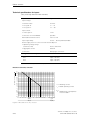
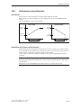
Derating . . . . . . . . . . . . . . . . . . . . .
What is derating?. . . . . . . . . . . . . . . . .
Derating factors . . . . . . . . . . . . . . . . .
Rear wall bus module installation . . . . . . . . .
Installation of special modules and motor starters
Installing the terminating module. . . . . . . . .
Connecting the cables . . . . . . . . . . . . . .
Fitting the caps . . . . . . . . . . . . . . . . . .
Removing the motor starters . . . . . . . . . . .
.
.
.
.
.
.
.
.
.
.
.
3-1
3-3
3-4
3-4
3-4
3-6
3-7
3-8
3-9
3-10
3-11
4
Commissioning and diagnostics . . . . . . . . . . . . . . . . . . .
4-1
4.1
4.2
4.3
4.3.1
Commissioning . . . . . . . . . . . . .
Configuration . . . . . . . . . . . . . .
Diagnostics . . . . . . . . . . . . . . .
Diagnostics and monitoring through the
4-1
4-3
4-5
4-5
.
.
.
.
.
.
.
.
.
.
.
.
. . . . . . . . . . . .
. . . . . . . . . . . .
. . . . . . . . . . . .
. . . . . . . . . . . .
. . . . . . . . . . . .
. . . . . . . . . . . .
connected/maximum
. . . . . . . . . . . .
. . . . . . . . . . . .
. . . . . . . . . . . .
.
.
.
.
.
.
.
.
.
.
.
.
.
.
.
.
.
.
.
.
.
.
.
.
.
.
.
.
.
.
.
.
.
.
.
.
.
.
.
.
.
.
.
.
.
.
.
.
.
.
.
.
.
.
.
.
.
.
.
.
.
.
.
.
.
.
.
.
.
.
.
.
.
.
.
.
.
.
.
.
.
.
.
.
.
.
.
.
.
.
.
.
.
.
. . . . . . .
. . . . . . .
. . . . . . .
user program
.
.
.
.
.
.
.
.
.
.
.
.
.
.
.
.
.
.
.
.
.
.
.
.
.
.
.
.
.
.
.
.
.
.
.
.
.
.
.
.
.
.
.
.
.
.
.
.
.
.
.
.
.
.
.
.
.
.
.
.
.
.
.
.
.
.
.
.
.
.
.
.
.
.
.
.
.
.
.
.
.
.
.
.
.
.
.
.
.
.
.
.
.
.
.
.
.
.
.
.
.
.
.
.
.
.
.
.
.
.
.
.
.
.
.
.
.
.
.
.
.
.
.
.
.
.
.
.
.
.
.
.
.
.
.
.
.
.
.
.
.
.
.
.
.
.
.
.
.
.
.
.
.
.
.
.
.
.
.
.
.
.
.
.
.
.
.
.
.
.
.
.
.
.
.
.
.
.
.
.
.
.
.
.
.
.
.
.
.
.
.
.
.
.
.
.
.
.
.
.
.
.
.
.
.
.
.
.
.
.
.
.
.
.
.
.
.
.
.
.
.
.
.
.
.
.
.
.
.
.
.
.
SIMATIC - ET 200pro motor starters
GWA 4NEB 950 5661-02 DS 06
v
4.4
4.4.1
4.4.2
4.4.3
4.4.4
4.5
4.5.1
4.5.2
4.6
LED indicators . . . . . . . . . . . . . . . . . . . . . .
Repair switch module (RSM) diagnostics . . . . . . . . .
Safety local repair switch module (F-RSM) diagnostics . .
400V shutdown module (ASM-400 V) diagnostics . . . .
DSe, sDSSte / sDSte, RSe, sRSSte / sRSte motor starter
diagnostics . . . . . . . . . . . . . . . . . . . . . . . .
Process image . . . . . . . . . . . . . . . . . . . . . .
Process image for special modules . . . . . . . . . . . .
Process image for motor starters. . . . . . . . . . . . .
Software ’ES Motor Starter’ . . . . . . . . . . . . . . .
.
.
.
.
.
4-9
4-11
4-11
4-12
4-17
5
General technical specifications . . . . . . . . . . . . . . . . . . .
5-1
5.1
5.2
Shipping and storage conditions . . . . . . . . . . . . . . . . . . . .
Mechanical and climatic environmental conditions . . . . . . . . . . .
5-1
5-2
6
Rear wall bus modules . . . . . . . . . . . . . . . . . . . . . . . .
6-1
6.1
6.1.1
Rear wall bus modules for special modules and motor starters. . . . .
Technical specifications. . . . . . . . . . . . . . . . . . . . . . . . .
6-1
6-2
7
Special modules. . . . . . . . . . . . . . . . . . . . . . . . . . . .
7-1
7.1
7.2
7.2.1
7.2.2
7.2.3
7.2.4
7.3
7.3.1
7.3.2
7.3.3
7.3.4
7.3.5
7.3.6
7.4
7.4.1
7.4.2
7.4.3
7.4.4
7.4.5
7.4.6
7.5
7.6
7.6.1
7.6.2
Overview . . . . . . . . . . . . . . . . . . .
Repair switch module (RSM) . . . . . . . . .
Features . . . . . . . . . . . . . . . . . . .
View of repair switch module . . . . . . . . .
Circuit diagram . . . . . . . . . . . . . . . .
Assignment of the main power connections .
Safety local repair switch module (F-RSM) . .
Features . . . . . . . . . . . . . . . . . . .
Description . . . . . . . . . . . . . . . . . .
View of the safety local repair switch module
Circuit diagram . . . . . . . . . . . . . . . .
Connection technology . . . . . . . . . . . .
Response in the case of a fault . . . . . . . .
400V shutdown module (ASM-400V) . . . . .
Features . . . . . . . . . . . . . . . . . . .
Description . . . . . . . . . . . . . . . . . .
View of 400 V shutdown module . . . . . . .
Circuit diagram . . . . . . . . . . . . . . . .
Assignment of the main power connections .
Response in the case of a fault . . . . . . . .
Power bus . . . . . . . . . . . . . . . . . .
Parameters and technical data . . . . . . . .
Parameters . . . . . . . . . . . . . . . . . .
Technical specifications. . . . . . . . . . . .
.
.
.
.
.
.
.
.
.
.
.
.
.
.
.
.
.
.
.
.
.
.
.
.
7-1
7-2
7-2
7-2
7-3
7-3
7-4
7-4
7-5
7-6
7-7
7-7
7-9
7-10
7-10
7-10
7-11
7-11
7-12
7-12
7-13
7-14
7-14
7-14
8
Motor starters . . . . . . . . . . . . . . . . . . . . . . . . . . . . .
8-1
8.1
8.1.1
8.1.2
Overview . . . . . . . . . . . . . . . . . . . . . . . . . . . . . . . .
Motor starters . . . . . . . . . . . . . . . . . . . . . . . . . . . . .
Electronic starters . . . . . . . . . . . . . . . . . . . . . . . . . . .
8-1
8-1
8-2
.
.
.
.
.
.
.
.
.
.
.
.
.
.
.
.
.
.
.
.
.
.
.
.
.
.
.
.
.
.
.
.
.
.
.
.
.
.
.
.
.
.
.
.
.
.
.
.
.
.
.
.
.
.
.
.
.
.
.
.
.
.
.
.
.
.
.
.
.
.
.
.
.
.
.
.
.
.
.
.
.
.
.
.
.
.
.
.
.
.
.
.
.
.
.
.
.
.
.
.
.
.
.
.
.
.
.
.
.
.
.
.
.
.
.
.
.
.
.
.
.
.
.
.
.
.
.
.
.
.
.
.
.
.
.
.
.
.
.
.
.
.
.
.
.
.
.
.
.
.
.
.
.
.
.
.
.
.
.
.
.
.
.
.
.
.
.
.
.
.
.
.
4-7
4-7
4-7
4-8
.
.
.
.
.
.
.
.
.
.
.
.
.
.
.
.
.
.
.
.
.
.
.
.
.
.
.
.
.
.
.
.
.
.
.
.
.
.
.
.
.
.
.
.
.
.
.
.
.
.
.
.
.
.
.
.
.
.
.
.
.
.
.
.
.
.
.
.
.
.
.
.
.
.
.
.
.
.
.
.
.
.
.
.
.
.
.
.
.
.
.
.
.
.
.
.
.
.
.
.
.
.
.
.
.
.
.
.
.
.
.
.
.
.
.
.
.
.
.
.
.
.
.
.
.
.
.
.
.
.
.
.
.
.
.
.
.
.
.
.
.
.
.
.
.
.
.
.
.
.
.
.
.
.
.
.
.
.
.
.
.
.
.
.
.
.
.
.
.
.
.
.
.
.
SIMATIC - ET 200pro motor starters
vi
GWA 4NEB 950 5661-02 DS 06
8.2
8.2.1
8.2.2
8.2.3
8.2.4
8.2.5
8.2.6
8.2.7
8.2.8
8.3
8.3.1
8.3.2
8.3.3
8.3.4
Motor starter properties . . . . . . . . . . . . . . . . . . . .
ET 200pro motor starters DSe ST, RSe ST . . . . . . . . . . .
ET 200pro motor starters DSe HF, RSe HF . . . . . . . . . . .
Electronic starters ET 200pro sDSSte / sDSte, sRSSte / sRSte .
View of DSe and RSe motor starters; Standard and high feature
View of electronic sDSSte / sDSte und sRSSte / sRSte starters
Connection technology . . . . . . . . . . . . . . . . . . . . .
Parameters . . . . . . . . . . . . . . . . . . . . . . . . . . .
Technical specifications. . . . . . . . . . . . . . . . . . . . .
sDSSte / sDSte / sRSSte / sRSte electronic starters . . . . . .
Physical principles . . . . . . . . . . . . . . . . . . . . . . .
Application and use. . . . . . . . . . . . . . . . . . . . . . .
Features . . . . . . . . . . . . . . . . . . . . . . . . . . . .
Notes on configuration . . . . . . . . . . . . . . . . . . . . .
.
.
.
.
.
.
.
.
.
.
.
.
.
.
8-3
8-3
8-3
8-4
8-4
8-5
8-6
8-10
8-13
8-17
8-17
8-21
8-22
8-32
9
Connection . . . . . . . . . . . . . . . . . . . . . . . . . . . . . .
9-1
9.1
9.1.1
9.1.2
9.2
9.2.1
9.2.2
9.2.3
9.2.4
9.3
9.4
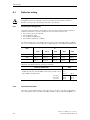
Rules for wiring . . . . . . . . . . . . . . . . . . . .
Selecting the energy lines . . . . . . . . . . . . . . .
Unused connections . . . . . . . . . . . . . . . . . .
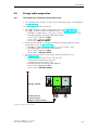
Energy cable preparation . . . . . . . . . . . . . . . .
The following is required for preparation work: . . . . .
Plug-in connector for RSM and F-RSM special modules
Plug-in connector for motor starters . . . . . . . . . .
Installing and wiring energy plug-in connectors. . . . .
Energy jumper plug. . . . . . . . . . . . . . . . . . .
Inputs with M12 connection . . . . . . . . . . . . . .
.
.
.
.
.
.
.
.
.
.
9-2
9-2
9-2
9-3
9-3
9-6
9-7
9-8
9-9
9-9
10
Device functions. . . . . . . . . . . . . . . . . . . . . . . . . . . .
10-1
10.1
10.2
10.2.1
10.2.2
10.3
10.3.1
10.3.2
10.3.3
10.4
10.4.1
10.4.2
10.4.3
10.4.4
10.5
10.5.1
10.5.2
10.5.3
10.6
10.7
10.7.1
10.7.2
10.7.3
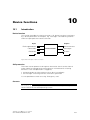
Introduction . . . . . . . . . . . . . . . . . . . . . . . . . . . .
Basic parameters . . . . . . . . . . . . . . . . . . . . . . . . . .
Device parameters . . . . . . . . . . . . . . . . . . . . . . . . .
Parameter – settings . . . . . . . . . . . . . . . . . . . . . . . .
Thermal motor model . . . . . . . . . . . . . . . . . . . . . . .
Device parameters . . . . . . . . . . . . . . . . . . . . . . . . .
Thermal motor model – settings . . . . . . . . . . . . . . . . . .
Messages and actions, measurements and statistics data . . . . .
Current limits . . . . . . . . . . . . . . . . . . . . . . . . . . . .
Device parameters . . . . . . . . . . . . . . . . . . . . . . . . .
Device parameters for current limit values – settings . . . . . . . .
Messages and actions . . . . . . . . . . . . . . . . . . . . . . .
Temperature sensor . . . . . . . . . . . . . . . . . . . . . . . .
Asymmetry . . . . . . . . . . . . . . . . . . . . . . . . . . . . .
Asymmetry parameter – descriptions . . . . . . . . . . . . . . .
Asymmetry parameter – settings . . . . . . . . . . . . . . . . . .
Messages, actions and measurements . . . . . . . . . . . . . . .
Trip reset . . . . . . . . . . . . . . . . . . . . . . . . . . . . . .
Inputs (can only be parameterized with high feature motor starters)
Device parameters . . . . . . . . . . . . . . . . . . . . . . . . .
Input parameters – settings . . . . . . . . . . . . . . . . . . . .
Messages and actions . . . . . . . . . . . . . . . . . . . . . . .
.
.
.
.
.
.
.
.
.
.
.
.
.
.
.
.
.
.
.
.
.
.
.
.
.
.
.
.
.
.
.
.
.
.
.
.
.
.
.
.
.
.
.
.
.
.
.
.
.
.
.
.
.
.
.
.
.
.
.
.
.
.
.
.
.
.
.
.
.
.
.
.
.
.
.
.
.
.
.
.
.
.
.
.
.
.
.
.
.
.
.
.
.
.
.
.
.
.
.
.
.
.
.
.
.
.
.
.
.
.
.
.
.
.
.
.
.
.
.
.
.
.
.
.
.
.
.
.
.
.
.
.
.
.
.
.
.
.
.
.
.
.
.
.
.
.
.
.
.
.
.
.
.
.
.
.
10-1
10-2
10-2
10-4
10-5
10-5
10-9
10-9
10-11
10-11
10-14
10-14
10-15
10-18
10-18
10-19
10-19
10-19
10-20
10-20
10-27
10-28
SIMATIC - ET 200pro motor starters
GWA 4NEB 950 5661-02 DS 06
vii
10.8 Soft-starter control function . . . . . . . . . . . . . . . .
10.9 Field bus interface . . . . . . . . . . . . . . . . . . . . .
10.9.1 Device parameters . . . . . . . . . . . . . . . . . . . . .
10.9.2 Device parameters for response on bus failure – settings .
10.10 Mechanical brake process . . . . . . . . . . . . . . . . .
10.10.1Device parameters . . . . . . . . . . . . . . . . . . . . .
10.10.2Parameters – settings . . . . . . . . . . . . . . . . . . .
10.10.3Message . . . . . . . . . . . . . . . . . . . . . . . . . .
10.11 Self-test . . . . . . . . . . . . . . . . . . . . . . . . . .
10.11.1 Messages . . . . . . . . . . . . . . . . . . . . . . . . .
10.12 Emergency start . . . . . . . . . . . . . . . . . . . . . .
10.12.1Message . . . . . . . . . . . . . . . . . . . . . . . . . .
10.13 Factory setting . . . . . . . . . . . . . . . . . . . . . . .
10.14 Maintenance . . . . . . . . . . . . . . . . . . . . . . . .
10.15 Reversing starter control function . . . . . . . . . . . . .
10.15.1Device parameters . . . . . . . . . . . . . . . . . . . . .
10.15.2Parameters – settings . . . . . . . . . . . . . . . . . . .
10.15.3Messages . . . . . . . . . . . . . . . . . . . . . . . . .
10.16 Electronic / mechanical switch technology . . . . . . . . .
10.16.1Messages and actions . . . . . . . . . . . . . . . . . . .
10.17 Local device interface . . . . . . . . . . . . . . . . . . .
10.18 Communication. . . . . . . . . . . . . . . . . . . . . . .
10.18.1Operating type monitoring . . . . . . . . . . . . . . . . .
10.18.2Commands . . . . . . . . . . . . . . . . . . . . . . . . .
10.18.3Plausibility check of data . . . . . . . . . . . . . . . . . .
10.18.4Output of messages . . . . . . . . . . . . . . . . . . . .
10.19 PROFIenergy . . . . . . . . . . . . . . . . . . . . . . . .
10.19.1What is PROFIenergy . . . . . . . . . . . . . . . . . . .
10.19.2PROFIenergy (version V1.0) in the ET 200pro motor starter
10.20 Log book . . . . . . . . . . . . . . . . . . . . . . . . . .
.
.
.
.
.
.
.
.
.
.
.
.
.
.
.
.
.
.
.
.
.
.
.
.
.
.
.
.
.
.
10-29
10-32
10-32
10-33
10-34
10-35
10-36
10-36
10-37
10-38
10-39
10-39
10-40
10-41
10-42
10-42
10-42
10-42
10-43
10-43
10-44
10-45
10-45
10-48
10-49
10-49
10-51
10-51
10-51
10-55
A
Order numbers . . . . . . . . . . . . . . . . . . . . . . . . . . . .
A-1
A.1
A.1.1
A.1.2
A.1.3
A.1.4
A.1.5
A.1.6
A.2
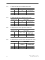
Motor starters . . . . . . . . . . . . . . . . . . . . . .
ET 200pro direct starters; Standard without inputs . . . .
ET 200pro direct starters; High feature with 4 inputs . . .
ET 200pro reversing starters; Standard without inputs . .
ET 200pro reversing starters; High feature with 4 inputs .
ET 200pro electronic starters; High feature with 4 inputs.
ET 200pro electronic reversing starters; High feature with
Components for ET 200pro motor starters . . . . . . . .
A-1
A-1
A-1
A-2
A-2
A-2
A-2
A-3
B
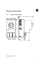
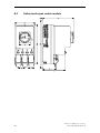
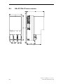
Dimensioned drawings . . . . . . . . . . . . . . . . . . . . . . . . . .
B-1
B.1
B.2
B.3
B.4
B.5
B.6
Repair switch module . . . . . . . . .
Safety local repair switch module. . . .
400 V shutdown module . . . . . . . .
DSe ST, RSe ST motor starters . . . . .
DSe HF, RSe HF motor starters. . . . .
sDSSte/sDSte, sRSSte/sRSte electronic
B-1
B-2
B-3
B-4
B-5
B-6
. . . . .
. . . . .
. . . . .
. . . . .
. . . . .
starters .
.
.
.
.
.
.
.
.
.
.
.
.
.
.
.
.
.
.
.
.
.
.
.
.
.
.
.
.
.
.
4
.
.
.
.
.
.
.
.
.
.
.
.
.
.
.
.
.
.
.
.
.
.
.
.
.
.
.
.
.
.
.
.
.
.
.
.
.
.
.
.
.
.
.
.
.
.
.
.
.
.
.
.
.
.
.
.
.
.
.
.
.
.
.
.
.
.
.
.
.
.
.
.
.
.
.
.
.
.
.
.
.
.
.
.
.
.
.
.
.
.
.
.
.
.
.
.
.
.
.
.
.
.
.
.
.
.
.
.
.
.
.
.
.
.
.
.
.
.
.
.
.
.
.
.
.
.
.
. . . .
. . . .
. . . .
. . . .
. . . .
. . . .
inputs
. . . .
.
.
.
.
.
.
.
.
.
.
.
.
.
.
.
.
.
.
.
.
.
.
.
.
.
.
.
.
.
.
.
.
.
.
.
.
.
.
.
.
.
.
.
.
.
.
.
.
.
.
.
.
.
.
.
.
.
.
.
.
.
.
.
.
.
.
.
.
.
.
.
.
.
.
.
.
.
.
.
.
.
.
SIMATIC - ET 200pro motor starters
viii
GWA 4NEB 950 5661-02 DS 06
C
Applications . . . . . . . . . . . . . . . . . . . . . . . . . . . . .
C.1
C.1.1
C.1.2
C.1.3
C.2
C.2.1
C.2.2
C.2.3
Standard applications . . . . . . . . . . . . . . . . . . .
With repair switch module and ECOFAST connection . .
No repair switch module . . . . . . . . . . . . . . . . .
For hot swapping . . . . . . . . . . . . . . . . . . . . .
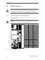
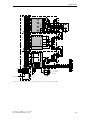
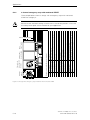
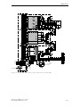
SAFETY applications . . . . . . . . . . . . . . . . . . .
1-channel emergency stop with monitored START . . . .
2-channel emergency stop with monitored START . . . .
Guard door monitoring 1-channel with automatic re-start .
.
.
.
.
.
.
.
.
C-2
C-2
C-4
C-6
C-8
C-8
C-10
C-12
D
Data formats and data records . . . . . . . . . . . . . . . . . . . .
D-1
D.1
D.2
D.2.1
D.3
D.4
D.5
D.5.1
D.5.2
D.5.3
D.5.4
D.5.5
D.5.6
D.5.7
D.6
D.6.1
D.6.2
D.6.3
D.7
D.7.1
D.7.2
D.8
D.8.1
Data formats . . . . . . . . . . . . . . . . . . . . . . .
Fault codes . . . . . . . . . . . . . . . . . . . . . . . .
Fault codes with negative data record acknowledgement
Data records . . . . . . . . . . . . . . . . . . . . . . .
DS68 process image for read/write outputs . . . . . . .
DS69 process image for the read / write inputs . . . . .
DS72 – Log book – Device faults . . . . . . . . . . . . .
DS73 – Log book – Read trips . . . . . . . . . . . . . .
DS75 – Log book – Read events . . . . . . . . . . . . .
DS81 – Read basic DS 131 setting . . . . . . . . . . . .
DS92 – Read device diagnostics . . . . . . . . . . . . .
DS93 – Write command . . . . . . . . . . . . . . . . .
DS94 – Read measurements . . . . . . . . . . . . . . .
DS95 - Read statistics . . . . . . . . . . . . . . . . . .
DS96 – Slave pointer . . . . . . . . . . . . . . . . . . .
DS100 – Read device identification . . . . . . . . . . . .
DS165 – Read / write comment . . . . . . . . . . . . .
Device parameters . . . . . . . . . . . . . . . . . . . .
DS131 – Device parameters . . . . . . . . . . . . . . .
DS134 – Maintenance . . . . . . . . . . . . . . . . . .
I&M data . . . . . . . . . . . . . . . . . . . . . . . . .
DS231 - device identification I&M 0 read . . . . . . . . .
.
.
.
.
.
.
.
.
.
.
.
.
.
.
.
.
.
.
.
.
.
.
.
.
.
.
.
.
.
.
.
.
.
.
.
.
.
.
.
.
.
.
.
.
.
.
.
.
.
.
.
.
.
.
.
.
.
.
.
.
.
.
.
.
.
.
.
.
.
.
.
.
.
.
.
.
.
.
.
.
.
.
.
.
.
.
.
.
.
.
.
.
.
.
.
.
.
.
.
.
.
.
.
.
.
.
.
.
.
.
.
.
.
.
.
.
.
.
.
.
.
.
.
.
.
.
.
.
.
.
.
.
.
.
.
.
.
.
.
.
.
.
.
.
.
.
.
.
.
.
.
.
.
.
.
.
.
.
.
.
.
.
.
.
.
.
.
.
.
.
.
.
.
.
.
.
.
.
.
.
.
.
.
.
.
.
.
.
.
.
.
.
.
.
.
.
.
.
.
.
.
.
C-1
D-1
D-3
D-3
D-5
D-6
D-7
D-8
D-9
D-10
D-12
D-12
D-18
D-20
D-21
D-22
D-24
D-25
D-26
D-26
D-34
D-35
D-35
Glossary . . . . . . . . . . . . . . . . . . . . . . . . . . . . . Glossary-1
Index . . . . . . . . . . . . . . . . . . . . . . . . . . . . . . . .Index-1
SIMATIC - ET 200pro motor starters
GWA 4NEB 950 5661-02 DS 06
ix
SIMATIC - ET 200pro motor starters
x
GWA 4NEB 950 5661-02 DS 06
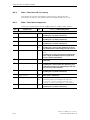
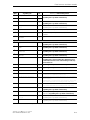
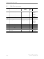
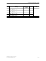
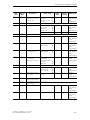
Figures
Figure 1-1:
Figure 1-2:
Figure 1-3:
Figure 2-1:
Figure 2-2:
Figure 2-3:
Figure 2-4:
Figure 2-5:
Figure 3-1:
Figure 3-2:
Figure 6-1:
Figure 7-1:
Figure 7-2:
Figure 7-3:
ET 200pro with motor starters . . . . . . . . . . . . . . . . . . .
ET 200pro with motor starters and electronic modules . . . . . .
ET 200pro with motor starters up to category 4 . . . . . . . . . .
Components and setup for the example . . . . . . . . . . . . . .
Set PROFIBUS address 6 . . . . . . . . . . . . . . . . . . . . .
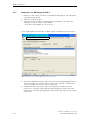
Circuitry for the example . . . . . . . . . . . . . . . . . . . . . .
Modules in ’HW Config’ . . . . . . . . . . . . . . . . . . . . . .
View of the ’DP-Slave Diagnostics’ status window . . . . . . . .
Installation position . . . . . . . . . . . . . . . . . . . . . . . . .
Derating diagrams . . . . . . . . . . . . . . . . . . . . . . . . .
Rear wall bus module . . . . . . . . . . . . . . . . . . . . . . .
View of repair switch module . . . . . . . . . . . . . . . . . . .
Circuit diagram for repair switch module . . . . . . . . . . . . . .
Assignment of the main power connections on the repair
switch module . . . . . . . . . . . . . . . . . . . . . . . . . . .
Figure 7-4: View of the safety local repair switch module . . . . . . . . . . .
Figure 7-5: Circuit diagram for safety local repair switch module . . . . . . .
Figure 7-6: Assignment of the main power connections on the safety
local repair switch module . . . . . . . . . . . . . . . . . . . . .
Figure 7-7: Assignment of the auxiliary circuits on the safety local repair
switch module . . . . . . . . . . . . . . . . . . . . . . . . . . .
Figure 7-8: Configuration of the safety local repair switch module . . . . . . .
Figure 7-9: View of 400 V shutdown module . . . . . . . . . . . . . . . . . .
Figure 7-10: 400V shutdown module circuit diagram . . . . . . . . . . . . . .
Figure 7-11: Assignment of the plugs on the 400V shutdown module . . . . .
Figure 7-12: Current flow in the power bus . . . . . . . . . . . . . . . . . . .
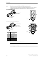
Figure 8-1: View of DSe and RSe motor starters; Standard and high feature .
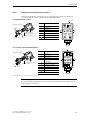
Figure 8-2: View of electronic sDSSte / sDSte und sRSSte / sRSte starters . .
Figure 8-3: Assignment of the main power connections on the motor starter .
Figure 8-4: Assignment of the M12 plug-in connector on the motor starter . .
Figure 8-5: Circuit diagram - DSe direct starter; Standard and high feature . .
Figure 8-6: Circuit diagram - RSe reversing starter; Standard and high feature
Figure 8-7: Electrical service life, contactor . . . . . . . . . . . . . . . . . .
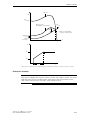
Figure 8-8: Typical current and torque curve of a three-phase
asynchronous motor . . . . . . . . . . . . . . . . . . . . . . . .
Figure 8-9: Current and torque curves for star-delta starting . . . . . . . . . .
Figure 8-10: Phase firing of the supply voltage by semiconductor elements
in the sDSSte / sRSSte soft starters . . . . . . . . . . . . . . . .
Figure 8-11: Current and torque curves for a soft starter . . . . . . . . . . . .
Figure 8-12: Time ramp / time diagram, sDSSte / sDSte, sRSSte / sRSte . . . .
Figure 8-13: Cyclic duration factor CD . . . . . . . . . . . . . . . . . . . . . .
SIMATIC - ET 200pro motor starters
GWA 4NEB 950 5661-02 DS 06
.
.
.
.
.
.
.
.
.
.
.
.
.
.
.
.
.
.
.
.
.
.
.
.
.
.
1-6
1-6
1-7
2-3
2-4
2-5
2-7
2-12
3-2
3-5
6-1
7-2
7-3
. .
. .
. .
7-3
7-6
7-7
. .
7-7
.
.
.
.
.
.
.
.
.
.
.
.
.
.
.
.
.
.
.
.
.
.
.
.
.
.
7-8
7-8
7-11
7-11
7-12
7-13
8-4
8-5
8-6
8-7
8-8
8-9
8-16
. .
. .
8-17
8-18
.
.
.
.
8-19
8-20
8-23
8-24
.
.
.
.
xi
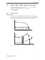
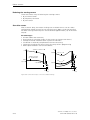
Figure 8-14: Load and motor torques and motor terminal voltage for operation
with soft starter . . . . . . . . . . . . . . . . . . . . . . . . . .
Figure 8-15: Reductions as a function of site altitude . . . . . . . . . . . . . .
Figure 9-1: Example: Power infeed . . . . . . . . . . . . . . . . . . . . . . .
Figure 9-2: Example: Power infeed with rotated socket insert . . . . . . . . .
Figure 9-3: Example: Power forwarding . . . . . . . . . . . . . . . . . . . .
Figure 9-4: Example: Motor connection cable . . . . . . . . . . . . . . . . .
Figure 9-5: Plug-in connector for RSM and F-RSM special modules . . . . . .
Figure 9-6: Plug-in connector for motor starters . . . . . . . . . . . . . . . .
Figure 10-1: Principle of device function . . . . . . . . . . . . . . . . . . . . .
Figure 10-2: Trip classes . . . . . . . . . . . . . . . . . . . . . . . . . . . . .
Figure 10-3: Cooling response with and without idle time . . . . . . . . . . .
Figure 10-4: Principle of anti-blocking function . . . . . . . . . . . . . . . . .
Figure 10-5: Soft startup / coasting down principle . . . . . . . . . . . . . . .
Figure 10-6: Switching example for mechanical brake process . . . . . . . . .
Figure 10-7: Local device interface . . . . . . . . . . . . . . . . . . . . . . .
Figure 10-8: Data channels . . . . . . . . . . . . . . . . . . . . . . . . . . .
Figure C-1: Design with repair switch module and ECOFAST connection . . .
Figure C-2: Design without repair switch module . . . . . . . . . . . . . . .
Figure C-3: Design for hot swapping . . . . . . . . . . . . . . . . . . . . . .
Figure C-4: Design with emergency stop 1-channel with monitored START . .
Figure C-5: Design with emergency stop 2-channel with monitored START . .
Figure C-6: Design for guard door monitoring 1-channel and automatic re-start
Figure D-1: Current formats . . . . . . . . . . . . . . . . . . . . . . . . . . .
Figure D-2: Byte layouts in the ’big endian’ format . . . . . . . . . . . . . . .
.
.
.
.
.
.
.
.
.
.
.
.
.
.
.
.
.
.
.
.
.
.
.
.
.
.
.
.
.
.
.
.
.
.
.
.
.
.
.
.
.
.
.
.
.
.
.
.
8-33
8-34
9-3
9-4
9-4
9-5
9-6
9-7
10-1
10-6
10-8
10-13
10-29
10-34
10-44
10-45
C-2
C-4
C-6
C-8
C-10
C-12
D-1
D-5
SIMATIC - ET 200pro motor starters
xii
GWA 4NEB 950 5661-02 DS 06
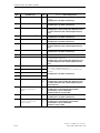
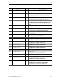
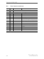
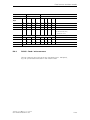
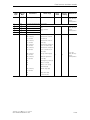
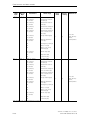
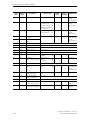
Tables
Table 1-1:
Table 1-2:
Table 1-3:
Table 1-4:
Table 1-5:
Table 1-6:
Table 2-1:
Table 2-2:
Table 3-1:
Table 3-2:
Table 3-3:
Table 3-4:
Table 3-5:
Table 3-6:
Table 3-7:
Table 4-1:
Table 4-2:
Table 4-3:
Table 4-4:
Table 4-5:
Table 4-6:
Table 6-1:
Table 7-1:
Table 7-2:
Table 8-1:
Table 8-2:
Table 8-3:
Table 8-4:
Table 8-5:
Table 8-6:
Table 8-7:
Table 9-1:
Table 9-2:
Table 9-3:
Table 9-4:
Table 10-1:
Table 10-2:
Table 10-3:
Basic components . . . . . . . . . . . . . . . . . . . . . . . . . . . . .
Special modules . . . . . . . . . . . . . . . . . . . . . . . . . . . . . .
Motor starters . . . . . . . . . . . . . . . . . . . . . . . . . . . . . . . .
Accessories . . . . . . . . . . . . . . . . . . . . . . . . . . . . . . . . .
Number of parameters of the modules . . . . . . . . . . . . . . . .
Maximum current-carrying capacity . . . . . . . . . . . . . . . . . .
Components for the example . . . . . . . . . . . . . . . . . . . . . .
Configuration table in ’HW Config’quot; . . . . . . . . . . . . . . . .
Installation measurements and clearances . . . . . . . . . . . . . .
Rear wall bus module installation . . . . . . . . . . . . . . . . . . . .
Repair switch module installation . . . . . . . . . . . . . . . . . . .
Installing the terminating module . . . . . . . . . . . . . . . . . . . .
Connecting the cables . . . . . . . . . . . . . . . . . . . . . . . . . .
Fitting the caps . . . . . . . . . . . . . . . . . . . . . . . . . . . . . . .
Removing motor starters . . . . . . . . . . . . . . . . . . . . . . . . .
Configuring motor starters . . . . . . . . . . . . . . . . . . . . . . . .
Fault types for special modules . . . . . . . . . . . . . . . . . . . . .
Fault types for motor starters . . . . . . . . . . . . . . . . . . . . . .
Status and fault displays via LEDs for DSe, sDSSte / sDSte, RSe,
sRSSte / sRSte . . . . . . . . . . . . . . . . . . . . . . . . . . . . . . .
Log book entries . . . . . . . . . . . . . . . . . . . . . . . . . . . . . .
System diagnostics . . . . . . . . . . . . . . . . . . . . . . . . . . . .
Technical specifications for rear wall bus module . . . . . . . . . .
Parameters of the special modules . . . . . . . . . . . . . . . . . . .
Technical specifications for the special modules . . . . . . . . . .
Motor starter overview . . . . . . . . . . . . . . . . . . . . . . . . . .
Parameters for DSe, RSe motor starters (standard and
high feature); sDSSte/sDSte, sRSSte/sRSte . . . . . . . . . . . . .
Technical specifications for the motor starters . . . . . . . . . . . .
Technical specifications for brake actuation . . . . . . . . . . . . . .
Technical specifications for inputs . . . . . . . . . . . . . . . . . . .
Switching frequencies with activated soft start function . . . . . .
Switching frequencies with deactivated soft start function
(direct start) . . . . . . . . . . . . . . . . . . . . . . . . . . . . . . . . .
Rules for wiring . . . . . . . . . . . . . . . . . . . . . . . . . . . . . . .
Installing and wiring energy plug-in connectors . . . . . . . . . . .
Energy jumper plug . . . . . . . . . . . . . . . . . . . . . . . . . . . .
M12 connection assignment . . . . . . . . . . . . . . . . . . . . . . .
Actual motor current . . . . . . . . . . . . . . . . . . . . . . . . . . . .
Basic parameter – settings . . . . . . . . . . . . . . . . . . . . . . . .
Thermal motor model device parameters - settings . . . . . . . .
.
.
.
.
.
.
.
.
.
.
.
.
.
.
.
.
.
.
1-1
1-2
1-3
1-4
1-8
1-8
2-2
2-7
3-3
3-6
3-7
3-8
3-9
3-10
3-11
4-3
4-5
4-6
.
.
.
.
.
.
.
4-9
4-14
4-16
6-2
7-14
7-14
8-2
.
.
.
.
.
8-10
8-13
8-15
8-16
8-25
.
.
.
.
.
.
.
.
8-30
9-2
9-8
9-9
9-9
10-3
10-4
10-9
SIMATIC - ET 200pro motor starters
GWA 4NEB 950 5661-02 DS 06
xiii
Table 10-4:
Table 10-5:
Table 10-6:
Table 10-7:
Table 10-8:
Table 10-9:
Table 10-10:
Table 10-11:
Table 10-12:
Table 10-13:
Table 10-15:
Table 10-16:
Table 10-17:
Table 10-18:
Table 10-19:
Table 10-20:
Table 10-21:
Table 10-22:
Table 10-23:
Table 10-24:
Table 10-25:
Table 10-26:
Table 10-27:
Table 10-28:
Table 10-29:
Table 10-30:
Table 10-31:
Table 10-32:
Table D-1:
Table D-2:
Table D-3:
Table D-4:
Table D-5:
Table D-6:
Table D-7:
Table D-8:
Table D-9:
Table D-10:
Table D-11:
Table D-12:
Thermal motor model – messages and actions . . . . . . . . .
Thermal motor model – Measurements and statistics data . .
Device parameters for current limit values – settings . . . . . .
Current limit values – messages and actions . . . . . . . . . . .
Temperature sensor parameter – settings . . . . . . . . . . . .
Temperature sensor – Messages and actions . . . . . . . . . .
Asymmetry parameter – settings . . . . . . . . . . . . . . . . . .
Asymmetry – Messages and actions . . . . . . . . . . . . . . . .
Asymmetry – measurements . . . . . . . . . . . . . . . . . . . .
Description of n input – action . . . . . . . . . . . . . . . . . . . .
Input parameters – settings . . . . . . . . . . . . . . . . . . . . .
Inputs – Messages and actions . . . . . . . . . . . . . . . . . . .
Soft starter control function parameter – settings . . . . . . . .
Device parameters for response on bus failure – settings . . .
Device parameters for mechanical brake process – Settings .
Mechanical brake process – message . . . . . . . . . . . . . . .
Self-test – test stages . . . . . . . . . . . . . . . . . . . . . . . . .
Self-test – Messages . . . . . . . . . . . . . . . . . . . . . . . . .
Emergency start – commands . . . . . . . . . . . . . . . . . . . .
Emergency start – message . . . . . . . . . . . . . . . . . . . . .
Factory setting – messages . . . . . . . . . . . . . . . . . . . . .
Device parameters for reversing starter control function –
settings . . . . . . . . . . . . . . . . . . . . . . . . . . . . . . . . . .
Reversing starter control function – messages . . . . . . . . . .
Electronic / mechanic switch technology –
messages and actions . . . . . . . . . . . . . . . . . . . . . . . .
Control priority of operating modes . . . . . . . . . . . . . . . .
Operating modes . . . . . . . . . . . . . . . . . . . . . . . . . . . .
Commands and their meaning . . . . . . . . . . . . . . . . . . . .
Communication – Messages . . . . . . . . . . . . . . . . . . . . .
Fault codes . . . . . . . . . . . . . . . . . . . . . . . . . . . . . . . .
DS68 process image for read/write outputs . . . . . . . . . . .
Meaning - Process image of the read / write outputs . . . . . .
DS69 process image for the read / write inputs . . . . . . . . .
Meaning - Process image of the read / write outputs . . . . . .
DS72 – Log book – Device faults . . . . . . . . . . . . . . . . . .
Messages in the log book – Device faults . . . . . . . . . . . .
DS73 – Log book – Read trips . . . . . . . . . . . . . . . . . . . .
Messages in the log book – Trips . . . . . . . . . . . . . . . .
DS75 – Log book – Read events . . . . . . . . . . . . . . . . . .
Messages in the log book – Events . . . . . . . . . . . . . . . .
DS92 – Read device diagnostics . . . . . . . . . . . . . . . . . .
..
..
..
..
..
..
..
..
..
..
..
..
..
..
..
..
..
..
..
..
..
.
.
.
.
.
.
.
.
.
.
.
.
.
.
.
.
.
.
.
.
.
10-9
10-10
10-14
10-14
10-16
10-17
10-19
10-19
10-19
10-22
10-27
10-28
10-31
10-33
10-36
10-36
10-37
10-38
10-39
10-39
10-40
.. .
.. .
10-42
10-42
..
..
..
..
..
..
..
..
..
..
..
..
..
..
..
..
..
10-43
10-46
10-47
10-48
10-49
D-4
D-6
D-6
D-7
D-7
D-8
D-8
D-9
D-9
D-10
D-11
D-12
.
.
.
.
.
.
.
.
.
.
.
.
.
.
.
.
.
SIMATIC - ET 200pro motor starters
xiv
GWA 4NEB 950 5661-02 DS 06
Table D-13:
Table D-14:
Table D-15:
Table D-16:
Table D-17:
Table D-18:
Table D-19:
Table D-20:
Table D-21:
Table D-22:
Structure of the command data record . .
DS93 – write command . . . . . . . . . . . .
DS94 – Read measurements . . . . . . . .
DS95 - Read statistics . . . . . . . . . . . . .
DS96 – Slave pointer . . . . . . . . . . . . . .
DS100 – Read device identification . . . . .
Time stamp . . . . . . . . . . . . . . . . . . .
DS131 – Device parameters . . . . . . . . .
DS134 - Maintenance . . . . . . . . . . . . .
DS231 - Read device identification I&M 0
..
..
..
..
..
..
..
..
..
..
..
..
..
..
..
..
..
..
..
..
..
..
..
..
..
..
..
..
..
..
..
..
..
..
..
..
..
..
..
..
..
..
..
..
..
..
..
..
..
..
..
..
..
..
..
..
..
..
..
..
..
..
..
..
..
..
..
..
..
..
.
.
.
.
.
.
.
.
.
.
D-18
D-18
D-20
D-21
D-22
D-24
D-25
D-26
D-34
D-35
SIMATIC - ET 200pro motor starters
GWA 4NEB 950 5661-02 DS 06
xv
SIMATIC - ET 200pro motor starters
xvi
GWA 4NEB 950 5661-02 DS 06
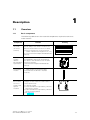
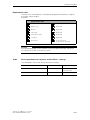
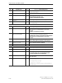
1
Description
1.1
Overview
1.1.1
Basic components
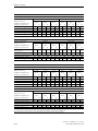
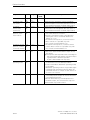
The following table shows the essential components required to construct
motor starters.
Component
Function
Module carrier, wide
(for motor
starters)
… is the mechanical carrier in which
the ET 200pro rear wall bus modules are
butt-mounted and the electronic modules
and motor starters are screw-mounted.
… can be ordered in the lengths 0.5 m, 1 m,
2 m (see manual ET 200pro Distributed I/O
Device).
Interface
module
IM 154-.
DP standard /
high feature
… connects the ET 200pro with
the PROFIBUS DP master and prepares
the data for the fitted electronic modules
and motor starters.
(see manual ET 200pro Distributed I/O
Device).
Terminating
module
… seals the bus on the last module
(included with the IM 154-. interface
module).
Rear wall
bus module
for motor
starters and
special
modules
… provides bus supply, forwards the supply
voltages for the electronics and actuator
control and houses:
• a special module
• a DSe (standard or high feature), sDSSte /
sDSte motor starter
• a RSe (standard or high feature), sRSSte /
sRSte reversing starter
(see chapter 6).
Drawing
Table 1-1: Basic components
SIMATIC - ET 200pro motor starters
GWA 4NEB 950 5661-02 DS 06
1-1
Description
Component
Rear wall bus
module for
safety local
repair switch
module
Function
Drawing
… houses a safety local repair switch
module.
Table 1-1: Basic components (Contd.)
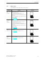
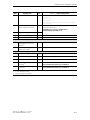
1.1.2
Special modules
Special modules are used if you
• … require a shutdown of the series-connected motor starters.
• … require safety up to category 4.
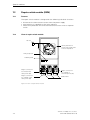
Repair switch
module
(RSM)
… with bus connection
… without digital inputs
… with SF-LED
… switches the power bus for the following
motor starters
… lockable disconnection function for
the main circuit
… for short-circuit protection
(see chapter 7.2).
Safety local
repair switch
module
(F-RSM)
… with bus connection
… with 3TK2841 functionality for
emergency stop
… with 2 digital inputs
… with 1 digital output
… with SF-LED
… switches the power bus for the following
motor starters
… lockable disconnection function for
the main circuit
… for short-circuit protection
(see chapter 7.3).
400V shutdown module
(ASM-400V)
… with bus connection
… without digital inputs
… with SF-LED
… switches off the power bus for
the following motor starters safely
(see chapter 7.4).
Drawing
ON
O
OFF
Function
ON
O
OFF
Component
Table 1-2: Special modules
SIMATIC - ET 200pro motor starters
1-2
GWA 4NEB 950 5661-02 DS 06
Description
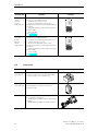
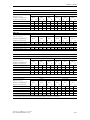
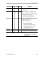
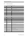
1.1.3
Motor starters
The table below shows the motor starter versions:
Component
Function
Direct starter
DSe;
Standard
Direct starter; Standard with electronic
overload protection
… switches a motor on or off.
… protects three-phase motors up to
5.5 kW in the event of overloading and short
circuiting.
… either with brake control, 400 V external
power supply.
… with SF-LED
(see chapter 8).
Reversing
starter
RSe;
Standard
Reversing starter; Standard with electronic
overload protection
… switches a motor rotating clockwise or
counterclockwise on or off.
… protects three-phase motors up to
5.5 kW in the event of overloading and short
circuiting.
… either with brake control, 400 V external
power supply.
… with SF-LED
(see chapter 8).
Direct starter
DSe;
High feature
… has the same features as a direct starter;
standard
… has an additional 4 digital inputs.
(see chapter 8).
Reversing
starter
RSe;
High feature
… has the same features as a reversing
starter; standard
… has an additional 4 digital inputs.
(see chapter 8.
Drawing
Table 1-3: Motor starters
SIMATIC - ET 200pro motor starters
GWA 4NEB 950 5661-02 DS 06
1-3
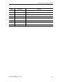
Description
Component
Function
Electronic
starter
sDSSte,
sDSte
High feature
Direct soft-starter; high feature with
electronic overload protection
… switches a motor on or off.
… protects three-phase motors up to
5.5 kW in the event of overloading and short
circuiting.
… either with brake control, 400 V external
power supply.
… with SF-LED
(see chapter 8).
Electronic
reversing
starter
sRSSte,
sRSte
High feature
Reversing soft starter; high feature with
electronic overload protection
… switches a motor rotating clockwise or
counterclockwise on or off.
… protects three-phase motors up to
5.5 kW in the event of overloading and short
circuiting.
… either with brake control, 400 V external
power supply.
… with SF-LED
(see chapter 8).
Drawing
Table 1-3: Motor starters (Contd.)
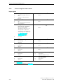
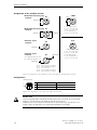
1.1.4
Accessories
Component
Function
Energy
jumper plug
… for forwarding the energy bus from
connection X3 to the next special module
or motor starter on connection X1.
Cap
for power bus
… seals the power bus on any connections
not required (not for power infeed on
connection X1)
Plug sets
… used to produce power cables and cables
for consumer connection.
… HAN Q4/2 is available with socket and pin
contacts.
… HAN Q8/0 is available with pin contacts.
Drawing
Table 1-4: Accessories
SIMATIC - ET 200pro motor starters
1-4
GWA 4NEB 950 5661-02 DS 06
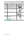
Description
Component
Function
Crimping
tools
… used to secure the socket and pin
contacts onto the ends of the cables.
… available for 0.14 - 4 mm2 and 4 - 6 mm2.
Removal tools
… are used to remove the contacts from
the plug housings.
… available for HAN Q4/2 and HAN Q8/0.
M12 cap with
O-ring
… used to cover the inputs not required.
PC cable with
RS232
… with optical interface for the communication with motor starters
Motor starter
ES software
on CD-ROM
… for:
• Parameterization
• Operate and observe
• Diagnostics
• Monitoring during ongoing operation
• Output of statistics data on preventative
maintenance, e.g. operating hours
(see chapter 4.6)
Drawing
Table 1-4: Accessories (Contd.)
SIMATIC - ET 200pro motor starters
GWA 4NEB 950 5661-02 DS 06
1-5
Description
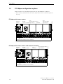
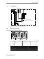
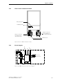
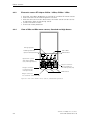
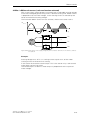
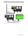
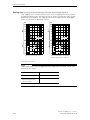
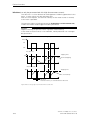
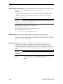
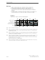
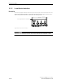
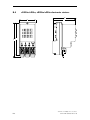
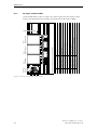
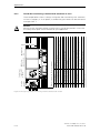
1.2
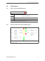
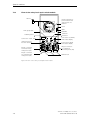
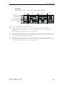
ET 200pro configuration options
Motor starters with the following features can be combined as follows:
• Motor starter; Standard and motor starter; High feature can be combined together in
any way.
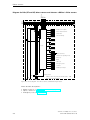
Interface
module
DSe,
Repair
sDSSte/ sDSte; DSe;
Standard
switch module High feature
RSe,
sRSSte/ sRSte
High feature
ON
OFF
O
Terminating module
ET 200pro with motor starters
Module carrier, wide (for motor starters)
Figure 1-1: ET 200pro with motor starters
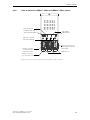
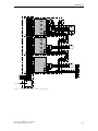
Interface
module
Repair
switch module
DSe;
Standard
RSe, sRSSte/ sRSte
High feature
ON
OFF
O
Terminating module
ET 200pro with motor starters and electronic modules
Module carrier, wide (for motor starters)
Figure 1-2: ET 200pro with motor starters and electronic modules
SIMATIC - ET 200pro motor starters
1-6
GWA 4NEB 950 5661-02 DS 06
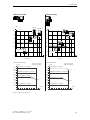
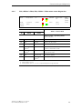
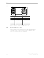
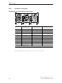
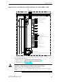
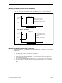
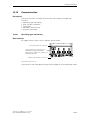
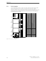
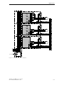
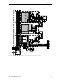
Description
Interface
module
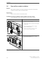
Safety local
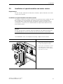
repair switch
module
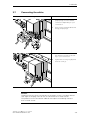
400V shutdown module
DSe;
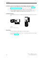
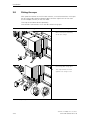
Standard
RSe, sRSSte/ sRSte
High feature
ON
OFF
O
Power infeed
Energy jumper plug
Terminating module
ET 200pro with motor starters up to category 4
Motor connection
Cap
Module carrier, wide (for motor starters)
Figure 1-3: ET 200pro with motor starters up to category 4
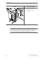
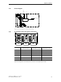
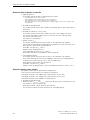
Parts list
The parts list below gives a list of all components required for an ET 200pro
sample configuration with motor starters (see figure 1-3).
Abbreviation
Order number
Description
—
6ES7194-4GB10-0AA0
Module carrier, wide (for motor starters), (length 1 m)
—
6ES7154-2AA00-0AB0
Interface module IM 154-2 DP high feature
with terminating module
—
3RK1922-2BA00
Rear wall bus module for special modules and motor starters
—
3RK1922-2BA01
Rear wall bus module for safety local repair switch module
F-RSM
3RK1304-0HS00-7AA0
Safety local repair switch module
ASM -400
3RK1304-0HS00-8AA0
400V shutdown module
DSe-ST
3RK1304-5xS40-4AA01) DSe direct starter; Standard
RSe-HF
3RK1304-5xS40-3AA01) RSe reversing starter; High feature
—
3RK1922-2BQ00
Energy jumper plug
—
3RK1902-0CJ00
3RK1902-0CK00
Cap for power bus
—
3RX9802-0AA00
Cap for unused M12 connections
—
3RK1911-2BE10
Plug set for power infeed (X1) for 4 mm2 HAN Q4/2
—
3RK1902-0CE00
Plug set for motor connection (X2) for 1.5 mm2 HAN Q8/0
1)
(x 10)
(x 1)
x = the current range should be selected according to your connected load
SIMATIC - ET 200pro motor starters
GWA 4NEB 950 5661-02 DS 06
1-7
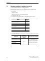
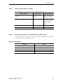
Description
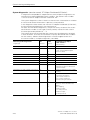
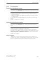
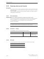
1.3
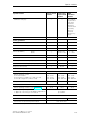
Maximum number of modules that can be
connected/maximum configuration
Please note the following rules when configuring your ET 200pro station:
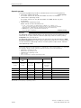
• The maximum number of modules totals 16.
This includes:
- Interface modules
- Electronic modules
- Modules for reserve
- Max. 8 special modules / motor starters permitted
• The maximum width is 1 m.
• The maximum current-carrying capacity of the power infeed is 25 A (4 mm2)
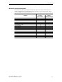
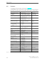
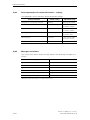
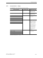
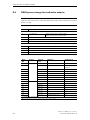
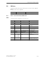
The table below shows the number of parameters of the individual modules in bytes:
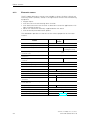
Module
PAA/PAE
(bytes)
Repair switch module
0/1
Safety local repair switch module
0/1
400V shutdown module
0/1
DSe; Standard
2/2
RSe Standard
2/2
sDSSte/ sDSte High feature
2/2
sRSSte/ sRSte High feature
2/2
Table 1-5: Number of parameters of the modules
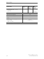
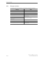
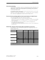
• The following table shows you the maximum current-carrying capacity of the modules
to take into consideration:
Component
Maximum
current-carrying
capacity
all motor starters
Repair switch module
Safety local repair
switch module
25 A
Modules that can be connected
The number of modules that can
be connected depends on the
total current of all the modules
in this potential group. This must
not exceed the relevant maximum current-carrying capacity.
400V shutdown module
Table 1-6: Maximum current-carrying capacity
SIMATIC - ET 200pro motor starters
1-8
GWA 4NEB 950 5661-02 DS 06
Description
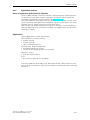
1.4
PROFIenergy
What is PROFIenergy
PROFIenergy is a manufacturer-independent profile on PROFINET. The profile
supports the shutdown in idle times (energy-saving function), measurement of
the energy flow (measurement function) and the status function that is used
to export the current status conditions and other information on PROFIenergy.
PROFIenergy uses field-tested PROFINET mechanisms ensuring rapid and
simple implementation
Origination
Both standards and regulations are increasingly focussing on environmental
protection and energy management as well as the desire to save energy costs
in a production plant and thus secure a sustainable competitive advantage.
As a result, the aim of industry is to save energy and to actively reduce CO2
emissions. The careful use of valuable resources means that the manufacturernonspecific PROFIenergy profile defined on PROFINET makes an active contribution to environmental protection.
PROFIenergy (Version1.0) in ET200pro motor starter
PROFIenergy allows consumption data from the equipment to be read in
a standardized format. This data is recorded during operation and displayed
on control device, for example, or transferred to higher level energy management software packages. This ensures that these measurements, as currently
present in motor starters, are available to the user for onward processing in
a standardized, manufacturer-nonspecific defined format and structure.
These PROFIenergy functions therefore form the basis for an active load and
energy management system in ongoing operations.
The system and device manufacturers provide the user with function blocks
for PROFIenergy and implement the relevant commands and status functions
in the field devices. The plant and machinery engineer and the plant operator
coordinate the switch-on and switch-off sequences as before, as well as the
enabling signals for the process. The control stores which components are
switched off with which pause type. The system operator does not need to
get involved with the technology in detail.
SIMATIC - ET 200pro motor starters
GWA 4NEB 950 5661-02 DS 06
1-9
Description
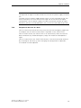
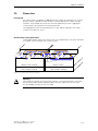
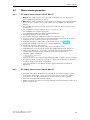
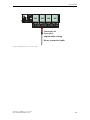
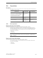
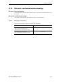
1.5
Guide to the ET 200pro manuals
The ET 200pro components are described in two manuals. The examples below
show the possible configurations of ET 200pro and the required manuals.
You use the following components …
ET 200pro consists of
the following components:
You need the information from
the following manuals:
ET 200pro Distributed I/O Device
ON
OFF
O
ET 200pro Distributed I/O Device
+
ET 200pro Motor Starters
The manuals are available in other languages on the internet.
SIMATIC - ET 200pro motor starters
1-10
GWA 4NEB 950 5661-02 DS 06
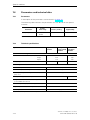
Description
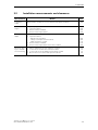
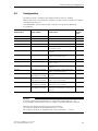
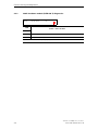
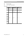
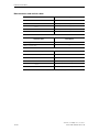
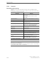
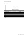
Where do you find information?
The following table is designed to help you quickly find the information you
need. It tells you which manual you need to refer to and which section deals
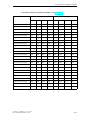
with the topic you are interested in.
Manual section/appendix
Subject
ET 200pro
Motor Starters
ET 200pro
Distributed I/O Device
ET 200pro components
1
2
Brief commissioning instructions
Installation
Commissioning and diagnostics
General technical specifications
Rear wall bus module
Special modules
Motor starters
Connection
Device functions
Order numbers
Dimensioned drawings
Applications
Data formats and data records
Glossary
2
3
4
5
6
7
8
9
10
A
B
C
D
Gl
—
4
7
11
—
—
—
5
9
A
A
—
—
Glossary
SIMATIC - ET 200pro motor starters
GWA 4NEB 950 5661-02 DS 06
1-11
Description
SIMATIC - ET 200pro motor starters
1-12
GWA 4NEB 950 5661-02 DS 06
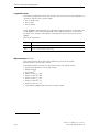
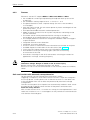
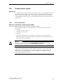
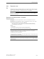
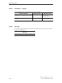
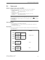
Brief instructions
2.1
2
Brief commissioning instructions
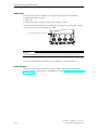
Introduction
The example below illustrates how to commission the ET 200S with motor
starters step by step.
DSe direct starter; By default is controlled by an ON button and an OFF button,
connected to an 8 DI 24V DC ST module.
The ’HW Config’ software in ’STEP 7’ is used for configuration.
Objective of the example
This example shall
1. show you how to commission a basic DSe direct starter; using ET 200pro
by default in just a few steps
2. let you modify this example for your application.
3. help you easily realize other applications.
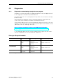
Essential steps
The essential steps with ET 200pro are always:
• Mounting of ET 200S components and the external wiring of control elements
(buttons) and actuators (e.g. motors)
• Configuration with STEP 7
• Integration into the user program
• Activation of the ET 200pro
• Evaluation of the diagnostics
SIMATIC - ET 200pro motor starters
GWA 4NEB 950 5661-02 DS 06
2-1
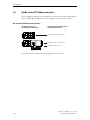
Brief instructions
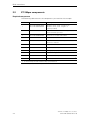
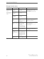
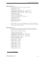
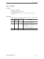
2.2
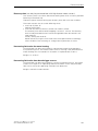
ET 200pro components
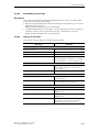
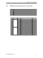
Required components
The following table contains the components you need for this example:
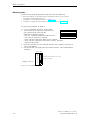
Number
Order number
Description
1
6ES7194-4GB00-0AA0
6ES7194-4GB10-0AA0
Module carrier, wide - length 0.5 m
Module carrier, wide - length 1 m
(either possible)
1
6ES7154-2AA00-0AB0
Interface module IM 154-2 DP high feature
with terminating module
1
6ES7194-4CB00-0AA0
Connection module CM 8xM12
1
6ES7141-4BF00-0AA0
Electronics module 8 DI 24V DC
2
3RK1922-2BA00
Rear wall bus module for special modules
and motor starters
1
3RK1304-0HS00-6AA0
Repair switch module
1
3RK1304-5xS40-4AA01)
DSe direct starter; standard
1
3RK1922-2BQ00
Energy jumper plug
2
3RK1902-0CK00
Cap for energy bus
1
3RK1911-2BE50
Connector set for power infeed (2.5 mm2)
1
3RK1902-0CC00
Connector set for motor connection (2.5 mm2)
1)
x = the current range should be selected according to your connected load
Table 2-1: Components for the example
SIMATIC - ET 200pro motor starters
2-2
GWA 4NEB 950 5661-02 DS 06
Brief instructions
2.3
Requirements
The requirements for the example are as follows:
• You have set up an S7 station, consisting of a power supply module and a DPV1
compatible master (e.g. CPU 315-2 DP(1), order number: 6ES7315-2AG10-0AB0).
For this example, a CPU 315-2 DP(1) was used as the DP master.
Every other DPV1 master (IEC 61784-1:2002 Ed1 CP 3/1 standard) can also be used,
of course.
• On your PG, STEP 7 (from V 5.3 with SP2) is fully installed. You have STEP 7
knowledge.
• The PG is connected to the DP master.
Note
Information regarding the operation of STEP 7 can be found in the online help.
2.4
Installation
Warning
Dangerous electrical voltage! This can lead to electrical shock and burns.
Before starting work, de-energize the plant and device.
Unused connections must be sealed using standard accessory components.
A1
Interface
module
A2
Repair
switch modul
A3
DSe;
Standard
A4
DI0.8
ON
OFF
O
Infeed
Cap
Module carrier, wide
A5
Terminating module
The following image shows you in which order you should mount the ET 200pro
components onto the module carrier.
Cap
Motor connection
Energy jumper plug
Figure 2-1: Components and setup for the example
SIMATIC - ET 200pro motor starters
GWA 4NEB 950 5661-02 DS 06
2-3
Brief instructions
Mounting order
A precise mounting description can be found for the following:
• IM 154 Installation of DP High Feature and digital modules in the manual
’ET 200pro Distributed I/O Device’
• Installation of rear wall bus modules in chapter 3.4
• Installation of repair switch modules and motor starters in chapter 3.5
For mounting, proceed as follows:
1. Install the module carrier on a solid base.
2. Start installing the individual modules onto
the module carrier from the left.
Observe the following order:
- IM 154-. interface module DP High Feature
- 8 DI 24V DC electronics module
- Rear wall bus module for repair switch module
- Rear wall bus module for DSe direct starters; Standard
- Terminating module
3. Place the relevant function module onto the rear wall bus module and
secure using bolts.
4. On the IM 154-. DP High Feature interface module, set the PROFIBUS
address 6.
OFF
PROFIBUS address 6
ON
64
32
16
8
4
2
1
Coding switch under screw cover
on the front side
Figure 2-2: Set PROFIBUS address 6
SIMATIC - ET 200pro motor starters
2-4
GWA 4NEB 950 5661-02 DS 06
Brief instructions
2.4.1
Circuitry of the example setup
Bus module
A1
Bus module
7
Terminating module
1L+
1M
2L+
2M
PROFIBUS-DP
The following image shows the circuitry of the main circuit and the control circuit for the example.
Bus module
7
7
IM 154
A3
A2
A4
IN1
IN2
IN3
IN4
RSM
Logic
DSe-ST
IN5
Logic
IN6
IN7
IN8
Q1
Q1
Logic
X3)
12 3
L1
L2
L3
PE
X2)
17 3
L1
L2
L3
PE
X1)
12 3
L1
L2
L3
PE
X3)
12 3
L1
L2
L3
PE
X2)
12 3
L1
L2
L3
PE
L1
L2
L3
PE
X1)
12 3
DI 8
A4
1
1
ON 13
M
3~
L1
L2
L3
PE
14
DC
24V
2 2
DI0 4
IN1
3
OFF
21
22
4 DI1
IN2
3
1M
5
5
FE
Figure 2-3: Circuitry for the example
SIMATIC - ET 200pro motor starters
GWA 4NEB 950 5661-02 DS 06
2-5
Brief instructions
2.5
Cabling and fitting
Perform the following steps:
1.
Caution
Provide sufficient short circuit and overload protection for the entire setup.
2. Cable the ET 200pro as shown in figure 2-3. Only the external lines shown in
bold should be connected. The functions are:
– 400 V AC and PE (power supply) on connection X1 of the repair switch
module
– Consumer (motor) on connection X2 of the motor starter
– Energy jumper plug between connection X3 of the repair switch
and connection X1 of the motor starter
– both switches for ON (NO contact) and OFF (NC contact) on electronics module 8 DI 24V DC
3. Seal the connection X2 of the repair switch module with a cap
4. Seal the connection X3 on the motor starter using a cap
5. Connect the DP Master to the ET 200pro using the PROFIBUS bus connection cable. The PROFIBUS DP interface is on the
IM 154-. DP High Feature.
6. Switch on the voltage supply for the DP master.
7. Observe the status LEDs on the DP master.
CPU 315-2 DP:
- 5 V DC green
- SF DP off
- BUSF flashes red
SIMATIC - ET 200pro motor starters
2-6
GWA 4NEB 950 5661-02 DS 06
Brief instructions
2.6
Configuration
1. Start the SIMATIC Manager and create a new project with a DP master
(e.g. CPU315-2 DP) (see figure 2-4).
2. Generate the PROFIBUS subnet.
3. Insert the ET 200pro on the PROFIBUS from the hardware catalog.
4. Set the PROFIBUS address 32 for ET 200pro.
5. If not already carried out, update your software (see chapter 4.2 - ’Updating
the software’), so that the ET 200pro modules are visible. Drag the individual
ET 200pro modules from the hardware catalog into the configuration table
(see figure 2-4).
6. For complete display of the parameter set for motor starters, in the screen
for the module IM 154-. under ’Operating parameters’, set the DP Alarm
Mode of ’DPV0’ (=preset) on ’DPV1’. If this is not possible, the CPU used
is not suitable for DPV1.
7. Parameterize the ’Response to residual current detection’ for the motor
starter for this example to "warning".
Module /
DP code
Order number
Input
address
2
3RK1304-0HS00-8AA0
0.0 - 0.7
3
3RK1304-5xS40-4AA01)
1.0 - 1.3
4
6ES7141-4BF00-0AA0
3.0 - 3.7
Output
address
Comment
Disconnecting
module
0.0 - 0.3
DSe motor starter
Electronics module
8 DI 24V DC
1) x = The current range should be selected according to your connected load
Table 2-2: Configuration table in ’HW Config’quot;
This should produce the following image.
Your file name
Figure 2-4: Modules in ’HW Config’
SIMATIC - ET 200pro motor starters
GWA 4NEB 950 5661-02 DS 06
2-7
Brief instructions
Setting the parameters for DP slave
8. To obtain diagnoses of the modules, set the following parameters for
the individual modules:
- In the properties of DP slave for ET 200pro dialog box
Start at setpoint <> actual setup: enable, module change in operation:
Enable
- in the dialog box Properties DP Slave for DSe, module / DP code 4
(in the configuration table), diagnostics: Enable group diagnosis
- for the motor starter, set the basic parameter for the rated operating
current
9. Save the configuration.
Setting the parameters for motor starters
10. As a minimum, set the rated operating current in the basic parameters of
the motor being operated on the motor starter. Other parameters can be
set as an option.
2.7
Integration into the user program
1. Create the user program using the KOP / AWL / FUP-Editor in the OB1.
AWL
U E
S A
UN E
R A
0.0
0.0
0.1
0.0
And input 0.0 (ON button)
Set output 0.0
And not input 0.1 (OFF button)
Reset output 0.0
2. Save the project in the SIMATIC Manager.
3. Load the configuration in the DP master.
SIMATIC - ET 200pro motor starters
2-8
GWA 4NEB 950 5661-02 DS 06
Brief instructions
2.8
Activation
1. Switch on the following voltage supplies on ET 200pro.
- 1L+ and 2L+ via the IM 154-. module
- Do not switch on the 400 V AC power supply!
2. Observe the status LEDs on the DP master and ET 200pro
- CPU 315-2 DP:
5V DC: Lights up
SF DP: off
BF: Off
3. Observe the status LEDs on the IM 154-. DP high feature.
- SF off
- BF off
- ON green
- 24 V DC green
4. Observe the status LEDs on the 8 DI 24V DC
- DI0 off
- DI1 green
- DI2 off
- DI3 off
5. Observe the status LEDs on the DSe motor starter
- SF off
- STATE off
- DEVICE green
SIMATIC - ET 200pro motor starters
GWA 4NEB 950 5661-02 DS 06
2-9
Brief instructions
Checking the wiring
Check the correct wiring of the ON and OFF buttons.
6. Press the ON switch
Observe the LEDs
- 8 DI 24V DC, DI0 green
- DSe motor starter, STATE green.
- DSe motor starter, DEVICE flashing in yellow.
- If on the motor starter DSe, SF is red, the parameter for
’Response to residual current detection’ should be set to "shut down".
Remove the ON command and to reset the fault,
switch the 1L+ voltage off for a brief time.
Danger
Make sure that no dangerous live parts can be touched.
7.
Switch on the supply voltage 400 V AC for the motor starter.
Warning
Make sure that the actuators connected to the motor starters do not present
a danger (e.g. uncontrolled rotary movements of the motor).
8. Repeat step 6 and observe the response of the connected consumer.
9. Press the OFF switch
Observe the LEDs
- 8 DI 24V DC, DI1 off
- DSe motor starter, STATE off.
- DSe motor starter, DEVICE green
SIMATIC - ET 200pro motor starters
2-10
GWA 4NEB 950 5661-02 DS 06
Brief instructions
2.9
Diagnostic options
There are several options for accessing the diagnostics of the ET 200pro
modules:
• Via the DP diagnostics modules for SIMATIC S7 "FB125" or "FC125".
You can download both modules or a description in *.pdf format on the Internet under:
http://support.automation.siemens.com/WW/view/de/387257
• Via ’HW Config’ S7.
See the following chapter 2.9.1
• Via the easy-to-use parameterization and diagnostics software ’ES Motor Starter’.
Using this software, which can be integrated into the S7, the ET 200pro motor
starters; parameterization, operation and monitoring (diagnostics) can be carried
out quickly and easily.
The software can be ordered online:
http://www.siemens.de/sirius/software
SIMATIC - ET 200pro motor starters
GWA 4NEB 950 5661-02 DS 06
2-11
Brief instructions
2.9.1
Diagnostics via ’HW Config’ of STEP 7
1. Open the ’HW Config’ window in the SIMATIC Manager on your computer
or programming device.
2. Open the "Online" station.
3. Simulate various windows and observe the messages in the ’DP Slave
Diagnostics’ status window, for example:
- Shut down the voltages 1L+ and / or 2L+
In the image below, for example, a motor starter is diagnosed on slot 2 and 3.
Your project path
Figure 2-5: View of the ’DP-Slave Diagnostics’ status window
4. After every performed action, press the F5 on the computer/programming
device to update the status window. The IM 154-. module is identified in
a fault message via a red dot with a white cross.
5. Double-clicking on the faulty station will display the module status of
the IM 154-. (’General’ tab). For precise fault diagnosis, select ’DP Slave
Diagnostics’. The individual diagnoses of the malfunctioning slave are shown
in text form.
SIMATIC - ET 200pro motor starters
2-12
GWA 4NEB 950 5661-02 DS 06
Brief instructions
2.10
Help
If you have problems or questions, please contact:
Technical Assistance: Telephone: +49 (911) 895-5900 (8 am - 5:00 pm CET) Fax: +49 (911) 895-5907
E-mail:
technical-assistance@siemens.com
Internet: www.siemens.com/industrial-controls/technical-assistance
SIMATIC - ET 200pro motor starters
GWA 4NEB 950 5661-02 DS 06
2-13
Brief instructions
SIMATIC - ET 200pro motor starters
2-14
GWA 4NEB 950 5661-02 DS 06
Installation
3.1
3
Installation rules
Install module carrier, wide
Information on the installation of the module carrier, wide, can be found in
the manual ’ET 200pro’ Distributed I/O Device.
Note the following during the installation process:
– Maximum permissible device length: 1 m
– A maximum of 8 motor starter modules can be operated on an ET 200pro interface
module
Easy installation
The ET 200pro distributed I/O device is designed for simple installation.
ET 200pro motor starters are designed as a complete device together with
a rear wall bus module (110 mm) on a module carrier, wide (press-drawn
section).
First fit the ET 200pro interface module IM 154-. onto the module carrier.
Then fit required rear wall bus modules in succession onto the right-hand side
of interface module IM 154-.
The function modules are fitted onto the rear wall bus modules in stages by
fitting them onto the right-hand side of the interface module IM 154-. or the
preceding module by fitting them on and then screwing them on using 3 Phillips
bolts.
SIMATIC - ET 200pro motor starters
GWA 4NEB 950 5661-02 DS 06
3-1
Installation
Installation rules for the configuration of an ET 200pro with motor starters
Observe the following rules for installation (see also figures in chapter 1.2
"ET 200pro configuration options"):
• The components are arranged in a single line on a module carrier, wide.
• Each line begins on the left with an IM 154-. interface module
• The ET 200pro distributed I/O device ends with the terminating module,
motor starter in addition with a cap for the X3 connection.
Installation position
The distributed I/O device is suitable for the following installations on a vertical
wall:
ON
ON
O
OFF
vertical
OFF
O
horizontal
Figure 3-1: Installation position
Please note:
During configuration, please observe the following points:
From an ambient temperature of Tu 40 °C, a derating may be required for motor
starters (see chapter 3.3).
SIMATIC - ET 200pro motor starters
3-2
GWA 4NEB 950 5661-02 DS 06
Installation
3.2
Installation measurements and clearances
Measurements
Module
mm
Installation
width
Rear wall bus module for motor starters and special modules
110
Installation
height
No
•
•
•
230
230
230
Installation
depth
On module carrier, wide, with rear wall bus module for:
• Special modules
- Repair switch module
- Safety local repair switch module
- 400V shutdown module
• Motor starter; standard
• Motor starter high feature with sensor cables
Minimum spacing for installation and wiring
•
•
•
•
power plug:
Special modules
Motor starter; standard
Motor starter high feature
Above and below the rear wall bus modules
To the left of the IM 154- interface module.
To the right of the ET 200pro terminating module
Below the motor starter and special modules
190
190
170
170
180
25
15
15
50
Table 3-1:Installation measurements and clearances
SIMATIC - ET 200pro motor starters
GWA 4NEB 950 5661-02 DS 06
3-3
Installation
3.3
Derating
3.3.1
What is derating?
Derating refers to the use of devices in difficult operating conditions by selectively limiting their performance. With special modules and motor starters,
these are operated at high ambient temperatures (>40 °C).
3.3.2
Derating factors
In the case of the ET 200pro special modules and motor starters, the following
factors must be taken into account and balanced against one another when
used in challenging ambient conditions:
• Ambient temperature Tu:
The ambient temperature Tu is the temperature surrounding the housing of
a special module and motor starter.
The lower the maximum ambient temperature Tu, the higher the current load
in the special modules and motor starters can be.
• Absolute current load Ie:
The lower the current through a special module and motor starter, the lower
the heat loss (= heat) within the device. If the device does not generate much
heat, the ambient temperature Tu can be higher.
SIMATIC - ET 200pro motor starters
3-4
GWA 4NEB 950 5661-02 DS 06
Installation
Horizontal assembly
Vertical assembly
ON
O
OFF
ON
O
OFF
Ie [A]
RSM ASM 400V
RSM
OFF
ON
30
O
ON
O
30
OFF
Ie [A]
25
ASM 400V
25
O
OFF
ON
F-RSM
20
20
10
O
10
OFF
15
ON
F-RSM
15
DSe, RSe
5
0
5
10
20
30
ϑu [°C]
40
+RUL]RQWDODVVHPEO\
60
sDSSte / sDSte
sRSSte / sRSte
,H>$@
$
50
:LWKE\SDVV$GHYLFH
0
$
$
$
$
$
$
$ :LWKRXWE\SDVV$GHYLFH
$
$
$
$
20
30
ϑu [°C]
40
:LWKE\SDVV$GHYLFH
$
'LUHFWVWDUWXSWR&ODVV$GHYLFH
$ :LWKRXWE\SDVV$GHYLFH
$
$
$
$
$
$
$
$ :LWKRXWE\SDVV$GHYLFH
$ :LWKRXWE\SDVV$GHYLFH
$
˽>r&@
60
50
sDSSte / sDSte
sRSSte / sRSte
,H>$@
$
'LUHFWVWDUWXSWR&ODVV$GHYLFH
10
9HUWLFDODVVHPEO\
$
$
DSe, RSe
$
$
˽>r&@
Figure 3-2: Derating diagrams
SIMATIC - ET 200pro motor starters
GWA 4NEB 950 5661-02 DS 06
3-5
Installation
3.4
Rear wall bus module installation
Features
Rear wall bus modules are used for the electrical connection of the special
modules and motor starters to the top module.
Requirements
Space is left for the IM 154 interface module.
Installing rear wall bus module for special modules and motor starters
The example below shows the installation of a rear wall bus module.
Drawing
Procedure
1
Check that the seals on the rear wall bus
module are correctly seated.
2
Insert the rear wall bus module into the installation plate and
3
allow the rear wall bus module to engage
into the installation plate.
4
Slide the rear wall bus module to the left
onto the modules already installed.
5
Allow the rear wall bus module to engage
into the adjacent module.
4
3
2
3
1
5
5
5
Table 3-2: Rear wall bus module installation
SIMATIC - ET 200pro motor starters
3-6
GWA 4NEB 950 5661-02 DS 06
Installation
3.5
Installation of special modules and motor starters
Requirements
All rear wall bus modules for electronics modules, special modules and motor
starters are installed.
Installation of special modules and motor starters
The special modules and motor starters are inserted onto the installed rear wall
bus modules and screwed onto the module carrier using 3 Phillips bolts.
The Phillips bolts are pre-fitted onto the special modules and motor starters
to avoid loss. A maximum of 3 ASM modules are permitted to be driven by
one F-RSM module.
Caution
Ensure that the seal is securely seated and observe the tightening torque of
the Phillips bolts of 1.5 Nm to ensure that the construction is fully sealed.
The table below uses an example of installing a repair switch module.
Drawing
Procedure / description
1
1
Set the repair switch with
the trunnion into both retainers
on the rear wall bus module.
2
Use a size 2 screwdriver to screw
the repair switch module using
the 3 Phillips bolts with a tightening torque of 1.5 Nm.
2
2
3 x 1.5 Nm
2
Table 3-3: Repair switch module installation
SIMATIC - ET 200pro motor starters
GWA 4NEB 950 5661-02 DS 06
3-7
Installation
3.6
Installing the terminating module
The last module to be installed with the ET 200pro distributed I/O device must
be the terminating module. The ET 200pro is ready for operation only when
the terminating module is inserted. The terminating module is included in
the delivery of the IM 154-.interface module. More information can be found
in the SIMATIC ET 200pro Distributed I/O Device manual.
Drawing
Procedure / description
2
1
1
Insert the terminating module
onto the module carrier until
it engages.
2
Slide the terminating module
to the left until it engages into
the last module.
3
Use a size 2 screwdriver to
secure the terminating module
using the 2 Phillips bolts at
a tightening torque of 1.5 Nm.
3 x 2)
Table 3-4:Installing the terminating module
SIMATIC - ET 200pro motor starters
3-8
GWA 4NEB 950 5661-02 DS 06
Installation
3.7
Connecting the cables
Drawing
Procedure / description
1
Insert the cables and energy
jumper plugs onto the relevant
connections depending on your
construction.
2
Then lock the inserted cables and
energy jumper plugs.
3
Insert the M12 cables into
the relevant connections according to your construction.
4
Tighten the securing ring by hand
as far as it will go.
1
1
1
2
4 3
Table 3-5:Connecting the cables
Caution
The plug insert on the X1 connection of the repair switch is installed rotated
180° against the plug insert on the X1 connection of a motor starter.
This prevents an X1 connection cable for the repair switch being inserted
onto a motor starter.
SIMATIC - ET 200pro motor starters
GWA 4NEB 950 5661-02 DS 06
3-9
Installation
3.8
Fitting the caps
With special modules and with motor starters, unused connections with caps
do not need to be sealed to protect open contacts against dirt and to seal
the ET 200pro securely in line with IP65.
The caps should be ordered separately.
Unused M12 connections must also be sealed using caps.
Drawing
Procedure / description
1/2
Screw the cap onto unused
M12 connections manually
as far as it will go.
3/4
Seal unused connections of
the energy bus using caps.
5
The caps can be secured
against loss using a cord.
1
2
3
3
4
5
Table 3-6:Fitting the caps
SIMATIC - ET 200pro motor starters
3-10
GWA 4NEB 950 5661-02 DS 06
Installation
3.9
Removing the motor starters
A motor starter can be removed from the rear wall bus module during operation.
The feeder must be de-energized, e.g. repair switch switched off. Remove
the cable to the motor and both energy jumper plugs on the left and right from
the motor starter to be replaced. Press the relevant locking lever on the plugs
downwards. Unfasten the 3 Phillips bolts as shown in the figure below and
remove the motor starter from the rear wall bus module.
Caution
If you remove more than one module from the ET 200pro, the station switches
to STOP.
The table below describes how to remove motor starters using the example
of a direct starter.
Drawing
7
23
6
Procedure / description
5
1
Ensure that the 400 V supply
is shut off (e.g. on the repair
switch).
If required, the repair switch can
be secured against reactivation
using a padlock.
2/3
Unscrew the connections for
the M12 cables.
4
Unlock the plugs or covers from
X1 to X3.
5/6/7
Remove the plugs and covers.
4
Table 3-7:Removing motor starters
SIMATIC - ET 200pro motor starters
GWA 4NEB 950 5661-02 DS 06
3-11
Installation
Drawing
Procedure / description
9
8
Unfasten the 3 Phillips bolts
on the motor starter.
9
Remove the motor starter
forwards.
8
8
8
Table 3-7:Removing motor starters (Contd.)
Note
It is advisable to inform maintenance and service personnel in detail about
correct handling of the motor starters before the system is handed over to
ensure that the advantages of ET 200pro can be deployed from the start.
SIMATIC - ET 200pro motor starters
3-12
GWA 4NEB 950 5661-02 DS 06
Commissioning and diagnostics
4.1
4
Commissioning
The motor starter modules are parameterized via the field bus standard procedure during startup. A change of parameters and B&B (operation and monitoring) can also be carried out during ongoing operation alternatively via bus and
the DP V1 mechanism or via the optical device interface on-site.
The group diagnostics parameter can be parameterized to disable or enable.
With disable, no fault messages are issued. In this case, the SF-LED when
a device diagnostics message occurs is no longer driven by the IM 154-. interface module.
A device fault can only be acknowledged via Power Off / On (1L+). If a faulty
response occurs repeatedly, the motor starter is faulty.
All other faults can be acknowledged via trip reset.
Attention
It is essential that the voltage tolerance for the 2L+ load power supply
(contactor and power electronics) is observed up to 55 °C: 20.4 V to 28.8 V.
Current set
With all motor starters you parameterize the current set via the relevant configuration and parameterization tool (e.g. GSD file, HW config, motor starter ES,
TIA portal, etc.).
External short-circuit protection
Safety note
External short-circuit protection
If the short-circuit current at the installation position of the motor starter, can
exceed the rated short-circuit breaking capacity (100 kA/400 V) of the integrated
fuses, you must provide additional external short-circuit protection (fuse or circuit breaker), see also chapter 7.4.
SIMATIC - ET 200pro motor starters
GWA 4NEB 950 5661-02 DS 06
4-1
Commissioning and diagnostics
After overload or short-circuit tripping
• After a short-circuit, the internal fuses and the switching elements may be
faulty in motor starters.
• After an overload trip - fuses OK - you have the option to reset the overload
trip via a reset.
Reset options are:
– Remote reset (via bus interface)
- cyclical process image (trip reset)
- via command ’trip reset’
– Local reset (via command)
– Trip reset via a parameterized input action on inputs 1-4 (only with motor
starters, high feature)
Caution
A reset is only accepted if the parameterized recovery time previously set is not
reached.
• Repair switch module or local safety module with integrated power switch of
size Ie 25 A.
Actuation value of the short-circuit protection at 13 x Ie.
Reset by pressing the rotary switch.
Disconnecting a load from the power supply
Pressing the rotary switch on the repair switch module in the OFF position gives
you the option to disconnect downstream consumers from the power supply.
Caution
Unplugging or plugging in a consumer during ongoing operation (i.e. under load)
is not permitted.
Reversing starters
Use the user program to ensure before a change of direction that the drive
is switched to "STOP" mode and remains in stop until the motor has stopped
turning.
SIMATIC - ET 200pro motor starters
4-2
GWA 4NEB 950 5661-02 DS 06
Commissioning and diagnostics
4.2
Configuration
Configuring means configuring and parameterizing the ET 200pro.
More information can be found in chapter 5 of the manual ’SIMATIC ET 200pro
Distributed I/O Device’.
The table below shows which STEP 7 version is required for operating
the modules.
Product label
Order number
Product brief
STEP 7
version
from
RSM
3RK1304-0HS00-6AA0
Repair switch module
5.3 SP2
F-RSM
3RK1304-0HS00-7AA0
Safety local repair switch module
5.3 SP2
ASM -400
3RK1304-0HS00-8AA0
400V shutdown module
5.3 SP2
DSe-ST
3RK1304-5xS40-4AA0
Direct starter; standard
5.3 SP2
DSe-ST
3RK1304-5xS40-4AA3
Direct starter; standard
with brake control
5.3 SP2
DSe-HF
3RK1304-5xS40-2AA0
Direct starter; High feature with
4 inputs
5.3 SP2
DSe-HF
3RK1304-5xS40-2AA3
Direct starter; High feature with
brake control and 4 inputs
5.3 SP2
RSe ST
3RK1304-5xS40-5AA0
Reversing starter; standard
5.3 SP2
RSe ST
3RK1304-5xS40-5AA3
Reversing starter; Standard with
brake control
5.3 SP2
RSe-HF
3RK1304-5xS40-3AA0
Reversing starter; High feature with
4 inputs
5.3 SP2
RSe-HF
3RK1304-5xS40-3AA3
Reversing starter; High feature with
brake control and 4 inputs
5.3 SP2
sDSSte/ sDSte
3RK1304-5KS70-2AA0
3RK1304-5LS70-2AA0
Electronic starter; High feature with
4 inputs
5.3 SP2
sDSSte/ sDSte
3RK1304-5KS70-2AA3
3RK1304-5LS70-2AA3
Electronic starter; High feature with
brake control and 4 inputs
5.3 SP2
sRSSte/ sRSte
3RK1304-5KS70-3AA0
3RK1304-5LS70-3AA0
Electronic reversing starter;
High feature with 4 inputs
5.3 SP2
sRSSte/ sRSte
3RK1304-5KS70-3AA3
3RK1304-5LS70-3AA3
Electronic reversing starter;
High feature with brake control and
4 inputs
5.3 SP2
Table 4-1: Configuring motor starters
Caution
If during the configuration process, the interface module IM 154-. and
the ET 200pro motor starters are not visible, a software update is required.
Observe the following sequence during installation:
[1] Hardware updates for ET 200pro IM 154-. - install.
[2] Hardware updates ET 200pro motor starter 3RK1304… - install.
SIMATIC - ET 200pro motor starters
GWA 4NEB 950 5661-02 DS 06
4-3
Commissioning and diagnostics
Software update
To update your software via the internet, proceed as follows:
1. Open the STEP 7 software ’HW config’
2. Open the menu option ’Tools’ > ’Install HW Updates’
3. In the screen that is opened, activate the ’Download from the internet’ option
(ensure that there is an active connection to the internet)
4. In the table, select the required updates or click the ’Select all’ button
5. Click ’Run’
6. The updates will be installed
SIMATIC - ET 200pro motor starters
4-4
GWA 4NEB 950 5661-02 DS 06
Commissioning and diagnostics
4.3
Diagnostics
4.3.1
Diagnostics and monitoring through the user program
Diagnostics and monitoring for ET 200pro take place via the user program and/
or the diagnostics channel of the PROFIBUS DP.
Any group faults (DI 0.2=1) and group warnings (DI 0.3=1) are sent to the input
process image.
For comprehensive diagnostic analysis and demo programs using STEP 5 and
STEP 7 see manual ’SIMATIC ET 200pro Distributed I/O Device’.
The S7 blocks FB125 and FC125 are available for diagnostic analysis in the user
program. The S7 blocks and the accompanying descriptions are available as free
downloads from the following addresses:
http://support.automation.siemens.com/WW/view/de/387257
http://support.automation.siemens.com/WW/view/de/5362473
In the following tables you will find the respective fault types and their meanings as a supplement to the channel-based diagnostics.
Fault types for special modules
Fault type
Repair switch module
Safety local repair
switch module
Meaning/cause
11000
Actuator shutdown
(F24)
• Module switched off
by hand
• tripped via shortcircuit
11000
Actuator shutdown
(F24)
• Module switched off
by hand
• tripped via shortcircuit
400V shutdown module 01001:
Fault (F9)
• Switching element
defective
Remedy
Rectify short-circuit.
Rectify short-circuit.
Replace device
Table 4-2: Fault types for special modules
SIMATIC - ET 200pro motor starters
GWA 4NEB 950 5661-02 DS 06
4-5
Commissioning and diagnostics
Fault types for motor starters
Motor starters
Fault type
Meaning/cause
Direct starter
DSe, sDSSte /
sDSte
00100:
Overload
(F4)
• Thermal motor model
overload
Reversing starter
RSe, sRSSte /
sRSte
00111:
Upper limit
violated
(F7)
• Ie upper current limit
violated
01000:
Lower limit
violated
(F8)
• Ie lower current limit
violated
01001:
Fault
(F9)
• Internal failure/device
fault
• Switching element
defective
Remedy
• Allow the motor to cool down
• Check the motor's current
consumption
• Check the set current limits
Switch the 1L+ supply voltage
on and off, if fault continues,
replace motor starter.
11000:
• Asymmetry
Actuator shutdown • Motor blocked
(F24)
• Residual current
detected
• Or in conjunction
with another type
of fault in this table
Check phases L1 to L3.
Clear stalled rotor.
Check main phases L1 to L3
for interruption.
11010:
External fault
(F26)
• Input tripping
• Input tripping limit
position
Eliminate the external fault
(withdraw from limit position,
for example)
00101
Overload
switching element
(F5)
• Thermal motor model
is at >178% load.
Shutdown as device
protection if "Thermal motor model"
parameter setting =
warning.
Check plant configuration
10001:
(F17)
• Switching element
power supply missing
Check 2L+
Table 4-3: Fault types for motor starters
SIMATIC - ET 200pro motor starters
4-6
GWA 4NEB 950 5661-02 DS 06
Commissioning and diagnostics
4.4
LED indicators
4.4.1
Repair switch module (RSM) diagnostics
Red
Group fault
SF
LED
Status / cause of fault
SF1)
Operating status
Red
Device fault (device diagnostics from interface module IM 154-. detected)
1) Status of the LEDs in this form only when group diagnostics activated
4.4.2
Safety local repair switch module (F-RSM) diagnostics
Red
Group fault
SF1)
POWER
L2 present
Green
Yellow
1-channel
operation
activated
1-CHANNEL
RUN
Output / F0
bar active
Green
Yellow
2-channel
operation
activated
2-CHANNEL
FAULT2)
Emergency
stop / emergency shutdown
Red
Green
Start signal
present
START
Green
Output set
OUT1
1)
2)
Status of the LEDs in this form only when group diagnostics activated
Flashes after starting operation for approx. 7 s due to self-test, change of the connection assignment in operation
or fault in the electronics
SIMATIC - ET 200pro motor starters
GWA 4NEB 950 5661-02 DS 06
4-7
Commissioning and diagnostics
4.4.3
400V shutdown module (ASM-400 V) diagnostics
Red
Group fault
SF
LED
Status / cause of fault
SF1)
Operating status
Red
Group fault (set by the IM 154-.) / device fault
1) Status of the LEDs in this form only when group diagnostics activated
SIMATIC - ET 200pro motor starters
4-8
GWA 4NEB 950 5661-02 DS 06
Commissioning and diagnostics
4.4.4
DSe, sDSSte / sDSte, RSe, sRSSte / sRSte motor starter diagnostics
Red
Group fault
SF
DEVICE
Device status
Red/
green/
yellow
Red/
green/
yellow
Contactor
status
STATE
In1-4
Input
1 to 4
Green
LEDs
Status / cause of fault
SF
STATE
Device
Device status / operating mode
Control by bus
Off
Green
Green
Motor on; no fault (cw or ccw with RSe)
Off
Off
Green
Motor off; No faults
Off
flickers green2)
Green
Motor on; Input control
Off
flashes
yellow1)
Green
Manual mode lost connection without
return to automatic mode
Off
flickers
yellow2)
Green
Shutdown via input control function
(e.g. Quick-Stop)
Off
Off
flashes red
Firmware update
Off
Off
flashes
green3)
Energy-saving mode active
1)
2)
3)
Flash frequency: 0.5 Hz
Flicker frequency: 8 to 10 Hz
Flashing sequence: 0.25 s on / 1.75 s off => unique flashing rhythm for energy-saving mode
Table 4-4: Status and fault displays via LEDs for DSe, sDSSte / sDSte, RSe, sRSSte / sRSte
SIMATIC - ET 200pro motor starters
GWA 4NEB 950 5661-02 DS 06
4-9
Commissioning and diagnostics
LEDs
Status / cause of fault
SF
STATE
Device
Off
Off
flickers red2)
Self-test running
Off
Off
flashes
green1)
Device not initialized
(send back device for repair)
Device fault
(fault sets group fault)
Red
Red
Red
Current flow present without switch-on
command (e.g. contactor welded shut)
Red
Off
Red
Electronics faulty, self-test fault
Red
Off
Off
No connection to rear wall bus interface
inside the device
Plant fault / warning
(device sets group fault)
Red
Off
Yellow
• No current flow despite switch-on
command (zero current detected)
• Internal shutdown
Off
green (with
switching element ON)
flashes
yellow1)
Group warning due to:
• Thermal motor model overload
• Asymmetry
• Current limit violation
• Group warning via input action
• Maintenance timer limit value exceeded
Red
Off
Off
Switching element power supply missing
Off
Off
flashes yellow
Switching element power supply missing
Parameterization (2)group warning
Red
Off
Off
No connection rear wall bus interface
inside the device (rear wall bus voltage
missing)
Off
Off
Off
Electronics power supply too low
Red
Off
Yellow
external short-circuit in transmitter supply
Plant fault (top module sets group fault)
Red
1)
2)
Off
Off
Device diagnostics present
(only if group diagnostics are enabled)
Flash frequency: 0.5 Hz
Flicker frequency: 8 to 10 Hz
Table 4-4: Status and fault displays via LEDs for DSe, sDSSte / sDSte, RSe, sRSSte / sRSte
(Contd.)
SIMATIC - ET 200pro motor starters
4-10
GWA 4NEB 950 5661-02 DS 06
Commissioning and diagnostics
4.5
Process image
4.5.1
Process image for special modules
Input signals
Repair switch
module
Safety Local repair
switch module
400V shutdown
module
DI 0.0
Module status:
Module status:
Module status:
0
ON
ON
OFF
1
OFF
OFF
ON
Status of the safety
bar
Status of the safety
bar
Bar not powered
Bar not powered
Bar powered
Bar powered
Not used
Not used
DI 0.1
0
Not used
1
DI 0.2
0
1
DI 0.3
0
1
DI 0.4
0
1
DI 0.5
Not used
0
1
DI 0.6
0
1
DI 0.7
0
1
SIMATIC - ET 200pro motor starters
GWA 4NEB 950 5661-02 DS 06
4-11
Commissioning and diagnostics
4.5.2
Process image for motor starters
Input signals
DI 0.0
Ready (automatic)
0
Starter not ready via host /
PLC
1
Starter can be operated
by host
DI 0.1
Motor on1)
0
Off
1
On (clockwise/counterclockwise rotation)
DI 0.2
Group fault
(short-circuit / overload)
DI 1.0
Bit 0
DI 1.1
No faults
1
Fault
DI 0.3
General warning
0
No warning
1
Warning
DI 0.4
Input 1
0
Not active
Motor current Iact2)
Bit 1
DI 1.2
(If one or more faults
described in table 4-6 occur,
"Group fault" is reported
irrespective of whether the
"Group diagnosis" parameter
(see chapter 7.6.1 and
chapter 8.2.4) is set to
"Disable" or "Enable").
0
Motor current Iact2)
Motor current Iact2)
Bit 2
DI 1.3
Motor current Iact2)
Bit 3
DI 1.4
Motor current Iact2)
Bit 4
1
Active
DI 0.5
Input 2
0
Not active
1
Active
DI 0.6
Input 3
DI 1.6
Manual local operating mode
0
Not active
0
Not active
1
Active
1
Manual operation local
DI 0.7
Input 4
DI 1.7
Ramp operation
(for soft starter)
0
Not active
0
Not active
Active
1
Active
1
1)
2)
DI 1.5
Motor current Iact2)
Bit 5
Signal is 1 if the motor current is >18.75% of the set rated current
See chapter 10.3.1
For a description of the parameters, see chapter 10.3
SIMATIC - ET 200pro motor starters
4-12
GWA 4NEB 950 5661-02 DS 06
Commissioning and diagnostics
Output signals
DO 0.0
Motor cw
0
Motor off
DO 1.0
Not used
1
Motor on
DO 0.1
Motor ccw (for RSe)
DO 1.1
Not used
0
Motor off
1
Motor on
DO 0.2
Brake actuation
DO 1.2
Not used
0
No drive
- brake active
- motor braked
1
Drive
- brake released
- motor unbraked
DO 0.3
Trip reset (edge 0
DO 1.3
Not used
0
Trip reset inactive
1
Trip reset active
DO 0.4
Emergency start
0
Not active
DO 1.4
Not used
1
Active
DO 0.5
Self-test
DO 1.5
Not used
0
Not active
1
Active
DO 0.6
Not supported
DO 1.6
Not used
DO 0.7
Not used
DO 1.7
Disable quick stop1)
0
not activated
1
activated
1)
1) High feature starter only
SIMATIC - ET 200pro motor starters
GWA 4NEB 950 5661-02 DS 06
4-13
Commissioning and diagnostics
Log book entries
The following log book entries are stored in the starter and can be exported via
’ES Motor Starter’ from version 2006:
• DS 72 device fault
• DS 73 trips
• DS 75 events
The 3 log books are organized as a ring buffer each of 126 bytes. The entries are
made together with the corresponding current operating hours of the device.
For each entry, 6 bytes are required, meaning that the last 20 entries remain
legible.
Format of the entries:
Byte
Meaning
0-3
Operating hours on device (h:mm:ss; storage in 1 s increments)
4-5
ID no. of device fault, trip, event
Table 4-5: Log book entries
Measurements (DS 94)
The measurements give the current operating status of the motor.
Measurements are transient values.
The following data are saved in data record 94 on the motor starter:
•
•
•
•
•
•
•
•
•
•
Remaining cool-down time of the motor1)
Motor heating
Asymmetry1)
Phase current IL1 (eff)
Phase current IL2 (eff)
Phase current IL3 (eff)
Phase current IL1 (%)
Phase current IL2 (%)
Phase current IL3 (%)
Time-based triggering of the thermal motor model
1) only with HF starters
SIMATIC - ET 200pro motor starters
4-14
GWA 4NEB 950 5661-02 DS 06
Commissioning and diagnostics
Statistics data (DS 95)
The following data are stored in the DS 95 of the starter:
•
•
•
•
•
•
•
•
•
•
•
•
•
•
•
•
Operating hours device
Operating hours - motor
Operating hours motor current = 18 … 49.9 % of Ie max1)
Operating hours motor current = 50 … 89.9 % x Ie max1)
Operating hours motor current = 90 … 119.9 % x Ie max1)
Operating hours motor current = 120 … 1000 % of Ie max1)
No. of starts, motor cw
No. of starts, motor ccw
Number of motor overload trips
Number of switching element overload trips
Last trip current IA (%)
Last trip current IA (eff)
Motor current Imax (%)
Motor current Imax (eff)
Number of starts output BO1)
Maintenance timer1)
With all ET 200pro motor starters, the operating hours are secured if the voltage fails
(a maximum of 6 minutes is lost). Statistics data can be exported via ’ES Motor Starter’
or via PLC DPV-1 with SFC59 or SFB 53.
Slave pointer (DS 96)
The slave pointers store the extreme values of individual measurements in
the time sequence. Slave pointers can be cleared or reset to "0" by the user
using the ’Clear slave pointer’ command.
The following data are stored in the DS 96:
•
•
•
•
•
•
•
•
•
•
•
•
•
•
•
•
•
•
•
Number of motor overload trips
Operating hours motor current =
Operating hours motor current =
Operating hours motor current =
Operating hours motor current =
Maximum trip current IA max(%)
Maximum trip current IA max(eff)
Phase current IL1 max(eff)
Phase current IL2 max (eff)
Phase current IL3 max (eff)
Phase current IL1 min(eff)
Phase current IL2 min (eff)
Phase current IL3 min (eff)
Phase current IL1 max (%)
Phase current IL2 max (%)
Phase current IL3 max (%)
Phase current IL1 min (%)
Phase current IL2 min (%)
Phase current IL3 min (%)
18 … 49.9 % of Ie1)
50 … 89.9 % of Ie1)
90 … 119.9 % of Ie1)
120 … 1000 % of Ie1)
1) only with HF starters
SIMATIC - ET 200pro motor starters
GWA 4NEB 950 5661-02 DS 06
4-15
Commissioning and diagnostics
System diagnostics (see also manual ’ET 200pro Distributed I/O Device’)
In diagnostics-compatible ET 200pro devices, device-specific diagnostics are
recorded via assigned PROFIBUS fault numbers. The relevant fault number
is issued to the ET 200pro interface module IM 154-. .
The system diagnostics show if there is a channel fault. Information on whether
or not channel-related information is present is also provided.
In the diagnostics data record (see manual "ET 200pro Distributed I/O Device“),
the channel-related diagnostics start from byte 19.
For each channel-related diagnostics, 3 bytes are always inserted. The associated DP fault number (= fault type) is binary-coded, inserted in each case in
the third byte on bit positions 0 … 4.
The stored values are extracted by the starter from the diagnostics recorded
in data record 92. As there are insufficient uniquely defined DP fault numbers
for the starters, different DS92 diagnostics must be mapped to one and
the same number (= multiple assignment; see table).
Channel-specific diagnostics
Single fault
DP
Fault no.
DS92:
Byte no.
1
22
Supported by ET 200pro
motor starters /
DS92 meaning
Reserved
32
Temperature sensor short-circuit
power switch tripped (repair
switch module)
4
23
Thermal motor model overload
Excess temperature
5
0
3
Upper limit exceeded
7
42
8
4
3
Ie limit value violated
0
4
Switching element defective
1
Short-circuit
Overload
Lower limit violated
Fault
9
Overload switching element
Ie limit exceeded
Parameterization fault
16
8
82
Invalid parameter value
Parameter change in ON status
not permissible
Transmitter or load voltage not present
17
10
Switching element power supply
missing
Actuator shutdown
24
24
41
44
46
47
Overload shutdown
Asymmetry shutdown
Ie limit value shutdown
Zero current shutdown
Motor blocking shutdown
External fault
26
33
Current limitation active
(sDSSte / sDSte and sRSSte /
sRSte)
Input tripping
Shutdown input
(ccw end position)
Shutdown input
(cw end position)
54
55
57
Table 4-6: System diagnostics
SIMATIC - ET 200pro motor starters
4-16
GWA 4NEB 950 5661-02 DS 06
Commissioning and diagnostics
Device diagnostics
In the input process image for the starters, the current group fault (DI 0.2)
and group warning messages (DI 0.3) are sent cyclically where necessary.
More in-depth information on the fault type are accessible where necessary
via a diagnostics call (V1-system diagnostics).
All device-specific diagnostics are summarized in the data record 92 (29 bytes).
The content of DS 92 can be exported using ’ES Motor Starter via the device
interface or online via DP V1 using the ’Read data record’ function.
4.6
Software ’ES Motor Starter’
Features
The ’ES Motor Starter’ software (from version 2006) offers you:
• Structured and tool-supported configuration of low-voltage switching devices
• Quick diagnostics
Local commissioning and monitoring on site such as:
• Parameter assignment during operation of the programmable controller and
control system
• Observation
• Diagnostics and testing
• Factory setting
• Read individual phase currents as direct values
• Residual current detection
• A parameterization block can be set
• Integrated online help
• Read statistics and measured values
SIMATIC - ET 200pro motor starters
GWA 4NEB 950 5661-02 DS 06
4-17
Commissioning and diagnostics
Application
The ’ES Motor Starter’ diagnostic and commissioning tool is suitable for
the following motor starters:
• DSe, RSe
• High feature DSe, sDSSte / sDSte, RSe, sRSSte / sRSte
The connection between the PC or programming device and the motor starter
is set up using an infrared RS232 PC cable.
Local optical device interface
Caution
To ensure fault-free data transfer, ensure that the infrared interface is clean.
You can find additional information on the software in the online help.
Order Numbers
The order numbers for the RS232 interface cable, USB cable, the ES Motor
Starter software can be found in the appendix under Components for ET 200pro
motor starters.
SIMATIC - ET 200pro motor starters
4-18
GWA 4NEB 950 5661-02 DS 06
General technical specifications
5.1
5
Shipping and storage conditions
Shipping and storage conditions
The motor starters fulfil the requirements according to IEC 61131, Part 2,
in regard to shipping and storage conditions. The following information applies
to modules that are shipped or stored in the original packaging.
Type of condition
Permissible range
Free fall
0.35 m
Temperature
from -40°C to +70°C
Temperature variation
20 K/h
Air pressure
from 1080 to 660 hPa
(corresponds to an altitude of -1000 to 3500 m)
Relative humidity
from 5 to 95 %, without condensation
SIMATIC - ET 200pro motor starters
GWA 4NEB 950 5661-02 DS 06
5-1
General technical specifications
5.2
Mechanical and climatic environmental conditions
Installation position
Horizontal installation on a vertical wall at a maximum inclination angle of 22.5°.
Mechanical environmental conditions
Oscillations tested in accordance with IEC 60068, Parts 2-6
•
•
Oscillation type:
Frequency sweeps with a rate of change of 1 octave
a minute
- 5 Hz < f < 9 Hz
Constant amplitude: 7 mm
- 9 Hz < f < 150 Hz
Constant acceleration: 2 g
Oscillation time:
10 frequency sweeps per axis in each of the 3 axes
arranged vertically in relation to each other
Shock tested to IEC 60068, Parts 2-27
•
•
•
Type of shock:
Intensity of shock:
Direction of shock:
Half sine
10 g peak value, 11 ms duration
3 shocks in the + / – directions in each of the 3 axes
arranged vertically in relation to each other
Climatic environmental conditions
Temperature
Temperature variation
-25 to 55 °C
10 K/h See installation rules chapter 3.1 ff.
Permissible rated current
see chapter 3.3
Relative humidity
from 5 to 95 %
Air pressure
from 1080 to 660 hPa
Corresponds to an
altitude of -1000 to
3500 m
Contaminant concentration
SO2 : < 0.5 ppm
rel. humidity < 60 %,
no condensation
Test:
10 ppm; 4 days
H2S: < 0.1 ppm
rel. humidity < 60 %,
no condensation
1 ppm; 4 days
SIMATIC - ET 200pro motor starters
5-2
GWA 4NEB 950 5661-02 DS 06
6
Rear wall bus modules
6.1
Rear wall bus modules for special modules and motor
starters
Features
• The 3RK1922-2BA00 rear wall bus module is suitable for housing a special
module or motor starter
• The 3RK1922-2BA01 rear wall bus module is suitable for housing a safety
local repair switch module
• Connection via plug
• Transfers the voltage for electronics / transmitter supply (1L+)
• Transfers the voltage for load power supply (2L+)
• Transfers the voltage for actuating the 400V shutdown module (ASM-400V)
• Transfers the data bus
Rear wall bus module layout
Snap-in nose
Snap-in nose
Retainers for spigot
of special modules
and motor starters
Busbars
Data bus
Snap-in nose
Snap-in nose
Coding for F-RSM with
3RK1922-2BA01
Connection for
special module or
motor starter
Figure 6-1: Rear wall bus module
SIMATIC - ET 200pro motor starters
GWA 4NEB 950 5661-02 DS 06
6-1
Rear wall bus modules
6.1.1
Technical specifications
Dimensions and weight
Installation dimensions W x H x D (mm)
110 x 130 x 22.5
Weight (g)
approx. 210
Shock protection
Type of protection according to IEC 60529
IP65 (following correct installation)
Rated data of the busbars
Power supply 1L+, 2L+
24 V DC
Current-carrying capacity Ie
10 A
Table 6-1: Technical specifications for rear wall bus module
SIMATIC - ET 200pro motor starters
6-2
GWA 4NEB 950 5661-02 DS 06
Special modules
7
Special modules are intended for power infeed, short-circuit protection and
shutdown for a series of downstream motor starters.
With the special modules ’Safety Local repair switch module’ and ’400V shutdown’, the safety level of category 4 can be achieved with the relevant wiring.
7.1
Overview
The following special modules are available:
• Repair switch module (RSM) (see chapter 7.2)
• Safety local repair switch module (F-RSM) (see chapter 7.3)
• 400V shutdown module (ASM-400V) (see chapter 7.4)
Parameters and technical specifications for the special modules, see chapter 7.6.
SIMATIC - ET 200pro motor starters
GWA 4NEB 950 5661-02 DS 06
7-1
Special modules
7.2
Repair switch module (RSM)
7.2.1
Features
The repair switch module is designed for the following individual functions:
• Disconnect the downstream starters from the power supply
• Start lockout via a padlock on the rotary element
• Shortcircuit protection for series-connected consumers with 25 A power
switch
7.2.2
View of repair switch module
≤8 mm
ON
OFF
O
Rotary element for
power switch with start
lockout via padlock
LED group fault
Labelling field
Plug-in connectors
for infeed of the
main power (X1)
Plug-in connectors
for outfeed of
the main power (X3)
Plug-in connectors
for outfeed of the
main power (X2)
Padlock bolt
Figure 7-1: View of repair switch module
SIMATIC - ET 200pro motor starters
7-2
GWA 4NEB 950 5661-02 DS 06
Special modules
L1 1
L2 2
L3 3
PE
X1)
1M
1L+
Circuit diagram
Data bus
7.2.3
7
DI 0.0
Q1
Module status
Logic
X3)
L1
L2
L3
PE
X2) 1 2 3
L1
L2
L3
PE
12 3
Figure 7-2: Circuit diagram for repair switch module
7.2.4
Assignment of the main power connections
1
2
3
4
3
4
11
12
11
12
11
12
3
4
1
2
1
2
X1)
X2)
X3)
Number
X1 connection
HAN Q4/2 (pin)
X2 connection
HAN Q4/2 (socket)
X3 connection
HAN Q4/2 (socket)
1
Phase L1
Phase L1
Phase L1
2
Phase L2
Phase L2
Phase L2
3
Phase L3
Phase L3
Phase L3
4
—
—
—
11
—
—
—
12
—
—
—
e
PE
PE
PE
Figure 7-3: Assignment of the main power connections on the repair switch module
SIMATIC - ET 200pro motor starters
GWA 4NEB 950 5661-02 DS 06
7-3
Special modules
7.3
Safety local repair switch module (F-RSM)
7.3.1
Features
Safety note
The module should be tested during commissioning and then every 12 months.
For the test, proceed as follows:
- Press the emergency stop switch
- Check that the OUT output has been switched off
- Check that the 400 V AC has been switched off
- Release the emergency stop switch
- With a monitored start, check that the OUT output and the 400 V are still
switched off; then press the START button
Repeat the test with the next emergency stop switch until all emergency stop
switches have been pressed.
The module with local safety function is designed for the following individual
functions:
• Has the same functions as a repair switch module
• 2 safe inputs for:
– Emergency stop / emergency off or safety door contacts, 2-channel
– Monitored start-up
• 2 safe outputs, incl.:
– 1 output on the front
– 1 output on the back with power infeed on 1 safety RW channel
• 2 sliding switches for setting the basic functions
– 1-channel / 2-channel
– Autostart / monitored start
• Low-demand and high-demand operating mode
• Use up to safety category 4 conforming to EN 954-1 or SIL 3 conforming
to IEC 61508
Caution
The safety local repair switch module can only be installed on the rear wall
bus module 3RK1922-2BA01.
SIMATIC - ET 200pro motor starters
7-4
GWA 4NEB 950 5661-02 DS 06
Special modules
7.3.2
Description
The safety local repair switch module includes a 3TK2841 module and is
equipped with M12 connections for connecting external safety components.
Either 1-channel or 2-channel emergency stop / emergency shutdown circuits or
safety door circuits can be connected to connection 1 (IN 1 / IN 2).
Both mechanical switches and electronic sensors can be connected. Electronic
sensors must be operated in the "1-channel mode" operating mode.
An external switch (NO contact) for monitored START can be connected (START)
on connection 2. The connected switch must not be pressed when switching
on or enabling the emergency stop / emergency shutdown function. The OUT
output or F0 bar is activated when the switch is released. The length of pressing
the switch should be in the range 200 ms … 5 s, otherwise this start command
is not accepted.
There is a safe output for connecting a door tumbler available (OUT) on
connection 3.
The required safety function can be set via 2 sliding switches located underneath the left-hand M12 opening.
The safe inputs are assigned to connection numbers 2 and 4.
The safe outputs are supplied with voltage via the rear wall bus module.
An output is looped through on the front and can be used to actuate a door
tumbler, for example (OUT).
The 2nd output switches the supply to the contactor coils (2L+) for the downstream motor starters via the rear wall bus module (F0).
Caution
The door tumbler above is only a simple mechanical lock, in other words this
door tumbler does not conform to the safety applications of category 4 conforming to EN 954-1, as a feedback of the mechanical lock bolts is not possible.
When connecting an electronic sensor with two outputs, ensure that the crosscircuit detection is realized in the sensor.
The electronic sensor and the ET 200pro station must be supplied from
the same power supply unit.
SIMATIC - ET 200pro motor starters
GWA 4NEB 950 5661-02 DS 06
7-5
Special modules
7.3.3
View of the safety local repair switch module
≤8 mm
ON
O
Rotary element for
power switch with
start lockout via
padlock
OFF
Fault
LED group fault
Labelling field
Connection 1 (IN1, IN2)
Sliding switch for
function selection
RUN
POWER
1-channel
2-channel
Connection 2 (START)
with status display
Connection 3 (OUT)
with status display
Plug-in connector
for infeed of the
main power (X1)
Plug-in connector
for outfeed of
the main power (X3)
Plug-in connector
for outfeed of the
main power (X2)
Padlock bolt
Figure 7-4: View of the safety local repair switch module
SIMATIC - ET 200pro motor starters
7-6
GWA 4NEB 950 5661-02 DS 06
Special modules
Circuit diagram
L1 1
L2 2
L3 3
PE
X1)
F0
Data bus
1L+
2L+
1M
2M
7.3.4
7
Q1
DI 0.0
Module status
DI 0.2
Safety output status
IN 1 emergency stop or guard door 1. Channel
IN 2 emergency stop or guard door 2. Channel
IN 3 monitored START
OUT
F0 power supply of the F0 bar
3TK2841
1-channel / 2-channel configuration
Monitored START / autostart configuration
Logic
X3)
L1
L2
L3
PE
X2) 1 2 3
L1
L2
L3
PE
12 3
Figure 7-5: Circuit diagram for safety local repair switch module
7.3.5
Connection technology
Assignment of the main power connections
1
2
3
4
3
4
11
12
11
12
11
12
3
4
1
2
1
2
X1)
X2)
X3)
Number
X1 connection
HAN Q4/2 (pin)
X2 connection
HAN Q4/2 (socket)
X3 connection
HAN Q4/2 (socket)
1
Phase L1
Phase L1
Phase L1
2
Phase L2
Phase L2
Phase L2
3
Phase L3
Phase L3
Phase L3
4
—
—
—
11
—
—
—
12
—
—
—
e
PE
PE
PE
Figure 7-6: Assignment of the main power connections on the safety local repair switch module
SIMATIC - ET 200pro motor starters
GWA 4NEB 950 5661-02 DS 06
7-7
Special modules
Assignment of the auxiliary circuits
Mechanical emergency stop IN1-channel
1
2
START
2L+ 1
2
5
Channel 1
5
3
4
4
3
INMechanical emergency stop IN2-channel
1
2
Channel 1
5
Channel 2
1:
2:
3:
4:
5:
Output (2L+)
not connected
not connected
Start input
not connected
3
4
Electronic sensor
1-channel
Pin
Pin
Pin
Pin
Pin
OUT
IN-
1
1
Channel 1
5
5
4
Electronic sensor
2-channel
3
OUT
1
Channel 1
2
1:
2:
3:
4:
5:
4
3
2M
not connected
not connected
Mass (2M)
F-output (2L+)
not connected
5
4
Pin
Pin
Pin
Pin
Pin
Pin
Pin
Pin
Pin
Pin
Channel 2
IN-
The operating mode should
be "1-channel operation“ set.
2
2
1:
2:
3:
4:
5:
3
Sensor channel
Sensor channel
not connected
Sensor channel
Sensor channel
1 output
2 F-input
1 F-input
2 output
Figure 7-7: Assignment of the auxiliary circuits on the safety local repair switch module
Configuration
Sliding switch
S1
1—
0—
S2
1
2-channel operation
autostart;
0
1-channel operation
Monitored START
S1 S2
Figure 7-8: Configuration of the safety local repair switch module
Safety note
The set configuration should be checked with the ’1-channel’ and ’2-channel’
displays. One of these two displays should always be lit.
If both are lit at the same time or are off at the same time, the device is no
longer ready for operation and should be replaced immediately.
SIMATIC - ET 200pro motor starters
7-8
GWA 4NEB 950 5661-02 DS 06
Special modules
Caution
Configuration changes must be carried out with the 2L+ power supply switched
off.
Changes with 2L+ power supply present result in a fault message and to shut
down the outputs. To reset the fault message and to transfer the changed
configuration, the 2L+ power supply must be switched off and back on again.
Electronic sensors must be operated in the "1-channel mode" operating mode.
7.3.6
Response in the case of a fault
With an internal or external fault (e.g. cross-circuit of the emergency stop lines),
the outputs are shut down and the fault is signalled via the ’FAULT’ LED.
With an external fault, the ’FAULT’ LED is on continuously. After the fault has
been corrected (e.g. enable emergency stop), the module can be operated
again.
With an internal fault, the ’FAULT’ LED flashes. If the fault cannot be resolved
by switching on and off, e.g. when changing the configuration in operation,
the module must be replaced.
SIMATIC - ET 200pro motor starters
GWA 4NEB 950 5661-02 DS 06
7-9
Special modules
7.4
400V shutdown module (ASM-400V)
7.4.1
Features
Safety note
The module should be tested on commissioning and after that,
every 12 months.
For the test, proceed as follows:
- The safety module supplying the F0 bar should be shut down.
- Check that the 400 V has been shut off.
- The safety module supplying the F0 bar should be switched on.
The 400V shutdown module is designed for the following individual functions:
• 2-way shutdown of the main circuit supply (category 4)
• Return message of the module functional status via bus
• Return message of the switching status of the contactor via bus
7.4.2
Description
The 400V shutdown module must only be used in combination with the safety
local repair switch module for local safety applications. It includes 2 series-connected contactors for the safety-oriented shutdown of the main supply circuit.
The operational switching of the connected consumer must be carried out via
a downstream motor starter. The auxiliary circuit supply of the device is provided via a safety bar in the rear wall bus module.
The 400V shutdown module can be used in combination with the safety local
repair switch module for safety applications up to category 4 conforming to
EN 954-1 or SIL 3 conforming to IEC 61508.
The operating mode is low-demand and high-demand.
Caution
The aggregate current via the 400V shutdown module must be max. 25 A.
Warning
With a load-side short-circuit (power switch on the F-RSM has tripped), there
is a risk of both contactors being welded in the ASM.
After a short-circuit shutdown, the ASM must therefore be checked for correct
functioning.
In switched off status, there must be no electrically conductive connection
between pins 1, 2 and 3 on the X1 connection and sockets 1, 2 and 3 on X2
connection.
Welding the contactors in the event of a short-circuit must be avoided via an
additional protection in the energy infeed with fuses (max. 16 A gL/gG NH
type 3NA, DIAZED type 5SB or NEOZED type 5SE).
SIMATIC - ET 200pro motor starters
7-10
GWA 4NEB 950 5661-02 DS 06
Special modules
7.4.3
View of 400 V shutdown module
LED group fault
Labelling field
Plug-in connector
for forwarding of
the main power (X2)
Plug-in connector
for infeed of the
main power (X1)
Padlock bolt
Figure 7-9: View of 400 V shutdown module
L1 1
L2 2
L3 3
PE
X1)
1M
OUT 2
2M
Circuit diagram
Data bus
1L+
7.4.4
7
Q1
DI 0.0
Module status
DI 0.1
Safety bar status
Logic
Q2
Q1
Q2
X2)
L1
L2
L3
PE
123
Figure 7-10: 400V shutdown module circuit diagram
SIMATIC - ET 200pro motor starters
GWA 4NEB 950 5661-02 DS 06
7-11
Special modules
7.4.5
Assignment of the main power connections
4
3
3
4
12
11
11
12
2
1
1
2
X1)
X2)
Number
X1 connection
HAN Q4/2 (pin)
X2 connection
HAN Q4/2 (socket)
1
2
3
4
11
12
Phase L1
Phase L2
Phase L3
—
—
—
PE
Phase L1
Phase L2
Phase L3
—
—
—
PE
e
Figure 7-11: Assignment of the plugs on the 400V shutdown module
7.4.6
Response in the case of a fault
If an internal fault occurs, the outputs remain without power and the fault
is signalled with the ’SF’ LED and notified via bus as diagnostics alarm.
In this case, the faulty module must be replaced.
SIMATIC - ET 200pro motor starters
7-12
GWA 4NEB 950 5661-02 DS 06
Special modules
7.5
Power bus
Load group
All motor starters supplied via one power bus infeed are referred to as a "load
group". Within a group of motor starters, another power bus infeed may be
required, for example to ensure that the rated operating current (aggregate
current) does not exceed the internal power bus.
The aggregate current of the power bus via the special modules and motor
starters must be max. 25 A.
Current flow via the power bus
The graphic below shows the current flow via the power bus using the example
of a repair switch module and a motor starter:
L1
L2
L3
T1
T2
T3
T1
T2
T3
Infeed
To load
To load
Jumper plug
Repair switch module
Motor starters
Rear wall bus module
Rear wall bus module
Figure 7-12: Current flow in the power bus
Warning
With special modules and with motor starters, unused connections with caps
do not need to be sealed to protect open contacts against dirt and to seal
the ET 200pro securely in line with IP65.
SIMATIC - ET 200pro motor starters
GWA 4NEB 950 5661-02 DS 06
7-13
Special modules
7.6
Parameters and technical data
7.6.1
Parameters
A description of the parameters can be found in chapter 10.
The following table indicates the parameters that can be set for the special
modules.
Action,
value range
Parameters
Group diagnostics
•
•
Factory setting
Disable
Enable
Disable
Applicability
Module
Table 7-1: Parameters of the special modules
7.6.2
Technical specifications
Repair switch
module
Special module
Safety local
repair switch
module
400V
shutdown
module
Dimensions and weight
Installation measurements (mm):
Width
Height
Depth
Weight (g)
110
230
170
1405
110
230
150
1600
2200
Module-specific data
Permissible position for use
any
Vibrostability conforming to IEC 60068, parts 2-6
2g
Shock-proofing conforming to IEC 60068,
parts 2-27
Assignment type conforming to IEC 947-4-1
Half-sine 10 g / 11 ms
2
1
Degree of contamination conforming
to IEC 60664 (IEC 61131)
3
Overvoltage category conforming to IEC 60664
II
Type of protection conforming to IEC 60529
Shock protection
IP65
finger-proof
Table 7-2: Technical specifications for the special modules
SIMATIC - ET 200pro motor starters
7-14
GWA 4NEB 950 5661-02 DS 06
Special modules
Special module
Repair switch
module
Safety local
repair switch
module
—
—
Utilization category
Maximum duration of use
no restriction
400V
shutdown
module
For conducting and shutting down
the rated
operating
current when
the safety
device is
pressed
(emergency
stop)
10 years
Safety guidelines
Category conforming to EN 954-1
—
4
4
—
3
3
Performance level (DIN EN ISO 13849-1)
—
e
e
Failure probability
—
—
5.358 x 10⁻¹¹
2.347 x 10⁻⁶
1 x 10-15
1 x 10-15
T1
—
10 years
10 years
B10
—
—
6 x 10⁵
Recovery time with emergency stop (enable)
—
min. 200 ms
—
Release time with emergency stop (trip)
—
30 ms
—
Response time (start)
—
40 ms
—
conforming to IEC 61508 (SIL level)
(PFH)
(PFD)
Control circuit
Rated operating voltage for electronics L+ / M
Rated operating current
from rear wall bus
from electronics supply 1L+ / 1M (no load)
from load voltage 2L+ / 2M (no load)
24 V DC (20.4 V - 28.8 V)
max. 3 mA
max. 4 mA
max. 20 mA
max. permissible line length
max. 3 mA
max. 4 mA
max. 120 mA
max. 3 mA
max. 4 mA
max. 600 mA
—
100 m
—
25 A
16 A
25 A
Main circuit
Rated operating current Ie (see chapter 3.3)
Rated operating voltage
• Approval conforming to EN 60947-1 Appendix N
• Approval conforming to CSA and UL
400 V
up to 400 V
up to 600 V
Rated short-circuit breaking capacity ICU
Instantaneous overcurrent release
50 kA at 400 V
fixed setting at 13 x I e
Connection cross-section power infeed
—
max. 6 x 4 mm²
Table 7-2: Technical specifications for the special modules (Contd.)
SIMATIC - ET 200pro motor starters
GWA 4NEB 950 5661-02 DS 06
7-15
Special modules
Special module
Repair switch
module
Safety local
repair switch
module
—
—
Switching times at 0.85 … 1.1 x U e
• Closing time
• Open delay
400V
shutdown
module
425…
525 ms1)
40 … 60 ms1)
Insulation resistance
Rated impulse strength Uimp
6 kV
Rated insulation voltage Ui
400 V
Protective separation between main and auxiliary
circuits
Circuits with rated voltage Ue against other
circuits or earth
• 0 V < Ue < 50 V
• 300 V < Ue < 600 V
1)
400 V, conforming to DIN EN 61140
Test voltage conforming to IEC 61131, Part 2
500 V DC
2.6 kV DC to ground
These values apply in combination with the F-RSM module
Table 7-2: Technical specifications for the special modules (Contd.)
SIMATIC - ET 200pro motor starters
7-16
GWA 4NEB 950 5661-02 DS 06
Motor starters
8.1
8
Overview
Due to the integrated electronic overload protection, a cover of the power range up
to 12 A with only two device versions is possible. The ET 200pro motor starters can
be parameterized and permit access to comprehensive diagnostic and statistics
data. The PC configuration tool ’ES motor starters’ is available for this purpose from
version 2006.
A connection to the motor starters can be established in two ways:
1. Locally on-site via the optical device interface of the motor starter
2. Remote on PROFIBUS DP via DPV1
Caution
Due to the operation of star-connected three-phase motors (especially if
<1 kW), high EMC interference may occur. Interference above the IEC limit
values can lead to an impairment of functions or failure of the electronics.
In case of high EMC interference, we recommend the use of motors with
EMC protection circuits.
(Exception: electronic starters may not be operated with a EMC protection
circuit).
The best filtering effect is achieved with three-phase RC interference inversion
modules.
Varistor interference inversion modules should not be used since they only
insufficiently filter out fast transients.
8.1.1
Motor starters
The ET 200pro motor starters are offered as direct (DSe) and reversing starters
(RSe) each in two versions:
• Standard series (code: DSe, RSe
– either with control for externally supplied brake with 400 V
– without digital inputs
• High feature range (short name for direct starters: DSe, RSe
– either with control for externally supplied brake with 400 V
– with 4 digital inputs
– with advanced parameterization options
SIMATIC - ET 200pro motor starters
GWA 4NEB 950 5661-02 DS 06
8-1
Motor starters
8.1.2
Electronic starters
The ET 200pro electronics starters are available as direct (sDSSte / sDSte) and
reversing starters (sRSSte / sRSte) in the high feature version with the following
equipment.
• 4 digital inputs
• with soft start and soft coasting-down function
• with deactivated soft start function as electronic starter for applications with
high switching frequency
• either with control for externally supplied brake with 400 V
• with advanced parameterization options
The table below provides an overview of the various properties of the motor
starters.
Feature
Standard
High
feature
Electronic starters
Installation width [mm]
110
For power ratings up to [kW] at 400 V AC
5.5
Integrated switchgear
SIRIUS contactor S00
Short-circuit protection via permanently
installed fuses
yes
Programmable electronic overload
protection
Switching function of main and auxiliary
contacts
Reversing contactor
and bypass relay
yes
mechanical
electronic
Rated operating current
0.15 - 2.0 / 1.5 - 12 A
Rated operating voltage
400 V AC
Parameterizable
CLASS tripping class
yes
10 (fixed)
5, 10, 15, 20
Asymmetry recognition
yes
Residual current detection
yes
Parameterizable current limits
no
yes, 2 limit values
Anti-blocking function with rapid
shutdown
no
yes
Assignment type conforming
to IEC 947-4-1
4 digital inputs
1
no
yes
Variant with / without brake function
yes
’ES Motor Starter’ usable?
yes
Derating in upper power range?
Diagnostics, fault types, see
yes (from tu = 40 °C)
yes (from tu = 40 °C)
chapter 4.3
Table 8-1: Motor starter overview
SIMATIC - ET 200pro motor starters
8-2
GWA 4NEB 950 5661-02 DS 06
Motor starters
8.2
Motor starter properties
8.2.1
ET 200pro motor starters DSe ST, RSe ST
• DSe ST are motor starters for a direction of rotation that can be used in
the ET 200pro distributed I/O device
• RSe ST are motor starters for two directions of rotation with mechanical lock
on cw and ccw motion that can be used in the ET 200pro distributed I/O
device
• Are suitable for switching and protecting three-phase loads up to 5.5 kW
at 400 V AC
• Are available in setting ranges of 0.15 - 2 A and 1.5 - 12 A
• are equipped with SIRIUS contactors
• Have parameterizable electronic overload protection
• Integrated residual current detection
• Asymmetry detection integrated (fixed limit value 30 % Ie)
• The as-is current is measured and the information transmitted to analyzers
• Detection of the switching status of the contactor
• Available diagnostic information of the motor starter (see table 4.3)
• Integrated log book functions with 3 device log books
• Integrated statistics data memory
• Circuit state and motor-starter status are indicated by LEDs
• Available either with control for externally supplied brake with 400 V AC
• Short-circuit protection via 3 fuses, meaning they can only be operated
without repair switch module / external short-circuit protection
• Separate supply voltage for
– Bus interface, electronics
– Contactor coils
• Manual control and local parameterization possible via optical device interface
• The power infeed, energy forwarding via a loop and load branch is provided
via power plug-in connector with padlock
• Firmware update via the optical device interface possible via specialist
personnel
8.2.2
ET 200pro motor starters DSe HF, RSe HF
• Have the same basic properties as the DSe ST and RSe ST motor starters
• Also have 4 digital inputs for 2-wire and 3-wire sensors with LED display.
The inputs can also be used for parameterized local control functions
• Have advanced parameterization options
• Upper and lower current limits can be defined and monitored for system and
process supervision
SIMATIC - ET 200pro motor starters
GWA 4NEB 950 5661-02 DS 06
8-3
Motor starters
8.2.3
Electronic starters ET 200pro sDSSte / sDSte, sRSSte / sRSte
• Have the same basic properties as the DSe HF and RSe HF motor starters
• Also have soft start and coasting down functions
• With the soft start function deactivated, the motor starter can be used as
an electronic direct and reversing starter
• Current limitation function
• Thermistor motor protection
8.2.4
View of DSe and RSe motor starters; Standard and high feature
LED group fault
Labelling field with
optical interface behind
LED STATE
LED DEVICE
Inputs IN 1 to IN 4
with status display
(only with high feature)
Plug-in connector
for infeed of the
main power (X1)
Plug-in connector
for forwarding of
the main power (X3)
Padlock bolt
Plug-in connector
for consumer connection (X2)
Figure 8-1: View of DSe and RSe motor starters; Standard and high feature
SIMATIC - ET 200pro motor starters
8-4
GWA 4NEB 950 5661-02 DS 06
Motor starters
8.2.5
View of electronic sDSSte / sDSte und sRSSte / sRSte starters
LED group fault
Labelling field with
optical interface behind
LED STATE
LED DEVICE
Inputs IN 1 to IN 4
with status display
Plug-in connector
for infeed of the
main power (X1)
Plug-in connector for
forwarding of the main
power (X3)
Padlock bolt
Plug-in connector
for consumer connection (X2)
Figure 8-2: View of electronic sDSSte / sDSte und sRSSte / sRSte starters
SIMATIC - ET 200pro motor starters
GWA 4NEB 950 5661-02 DS 06
8-5
Motor starters
8.2.6
Connection technology
Assignment of the main power connections
4
3
12
11
2
1
X1)
1)
6 47
8 5
1
3
2
X2)
Number
X1 connection
HAN Q4/2 (pin)
1
2
3
4
11
12
1
2
X3)
X2 connection
HAN Q8/0 (socket)
X3 connection
HAN Q4/2 (socket)
Phase L1
L1 out
Phase L1
Phase L2
Not used
Phase L2
3
Phase L3
L3 out
Phase L3
4
Not used
Brake L1 (switched)
5
—
6
—
Brake L3 (direct)
7
—
L2 out
8
—
Temperature sensor
Not used
1)
—
—
—
Temperature sensor
1)
—
11
Not used
—
Not used
12
Not used
—
Not used
e
PE
PE
PE
only sDSSte / sDSte and sRSSte / sRSte
Figure 8-3: Assignment of the main power connections on the motor starter
SIMATIC - ET 200pro motor starters
8-6
GWA 4NEB 950 5661-02 DS 06
Motor starters
Auxiliary circuits
There are the following auxiliary circuits on a ET 200pro motor starter:
• 1L+ Electronic voltage supply via the rear wall bus module to supply
electronics and connected sensors on inputs IN 1 to IN 4.
• 2L+ Load power supply ( 24 V DC) via the rear wall bus module for actuation
of the contactor.
• Sensor supply via M12 plug-in connector. Connections 2 and 4 are bridged.
Connection 5 is inside the device connection to functional earth.
The image below shows the assignment
+24 V
DI x
1
2
4
3
5
DI x
0V
FE (functional earth)
Figure 8-4: Assignment of the M12 plug-in connector on the motor starter
SIMATIC - ET 200pro motor starters
GWA 4NEB 950 5661-02 DS 06
8-7
Motor starters
Data bus
1L+
1M
2L+
2M
Diagram for DSe (ST and HF) direct starters and electron. sDSSte / sDSte starters
7
L1 1
L2 2
L3 3
PE
X1)
1 L1
2 L2
3 L3
X3) PE
DI 0.0
Ready from host/PLC
DI 0.1
Motor ON/current flow
DI 0.2
Group fault
DI 0.3
General warning
Input 12)
DI 0.4
Input 22)
DI 0.5
Input 32)
Logic
DI 0.6
Input 42)
DI 0.7
DI 1.0 - 1.5 Motor current Iact
DI 1.6
Manual local operating mode
DO 0.0
Motor cw
DO 0.2
Brake
DO 0.3
Trip reset
DO 0.4
Emergency start
DO 0.5
Self-test
DO 1.7
Disable quick stop2)
Q1
Auxiliary switch
Q1
1) Brake control only with order number suffix … AA3
1 7 3 X2)
2) not present with standard
L1
L2
L3
1) 6
Br.
Br.
PE
4
Figure 8-5: Circuit diagram - DSe direct starter; Standard and high feature
More detailed descriptions:
• Motor current Iact in ’Actual motor current’, page 10-3
• Inputs / actions in chapter 10.7
• Emergency start in chapter 10.12
SIMATIC - ET 200pro motor starters
8-8
GWA 4NEB 950 5661-02 DS 06
Motor starters
Data bus
1L+
1M
2L+
2M
Diagram for rev.-starter RSe (ST and HF) and electron. rev.-starter sRSSte / sRSte
7
L1 1
L2 2
L3 3
PE
X1)
1 L1
2 L2
3 L3
X3) PE
DI 0.0
Ready from host/PLC
DI 0.1
Motor ON/current flow
DI 0.2
Group fault
General warning
DI 0.3
Input 12
)
DI 0.4
Input 22)
DI 0.5
Logic
Input 32)
DI 0.6
Input 42)
DI 0.7
DI 1.0 - 1.5 Motor current Iact
Q1
Q1
Q2
DI 1.6
Manual local operating mode
DO 0.0
Motor cw
DO 0.1
Motor ccw
DO 0.2
Brake
DO 0.3
Trip reset
DO 0.4
Emergency start
DO 0.5
Self-test
DO 1.7
Disable quick stop2)
Q2
Auxiliary switch
1) Brake control only with order number suffix … AA3
1 7 3 X2)
2) not present with standard
L1
L2
L3
Br.
Br.
PE
4
1) 6
Figure 8-6: Circuit diagram - RSe reversing starter; Standard and high feature
More detailed descriptions:
• Motor current Iact in ’Actual motor current’, page 10-3
• Inputs / actions in chapter 10.7
• Emergency start in chapter 10.12
Danger
Hazardous voltage. Danger of death or risk of serious injury.
Before starting work, de-energize the plant and device.
Phase L1 is not run via the semiconductor in the sDSSte / sDSte and sRSSte /
sRSte.
SIMATIC - ET 200pro motor starters
GWA 4NEB 950 5661-02 DS 06
8-9
Motor starters
8.2.7
Parameters
A description of the parameters can be found in chapter 10.
The table below shows which actions or value ranges can be set for the relevant
parameters for motor starters DSe / sDSSte / sDSte and RSe / sRSSte /sRSte.
Parameters
Rated operating current
• Range 1
• Range 2
Behavior with supply voltage
switching element missing
Load type
Response on overload thermal motor model1)
Warning limit value1)
• Motor heating
• time-based trigger
reserve
Recovery time
Action, value range
Factory setting
Increment 10 mA
• 0.15 to 2 A (0.07 to 0.9 kW)
• 1.5 to 12 A (0.7 to 5.5 kW)
• Group fault
• Group fault for ON command
• General warning
• 3 - phase motor
• 1-phase motor
(not with electronic starters)
• Shutdown without restart
• Shutdown with restart
• Warning
GSD/device
• 0.15 / 2 A
• 1.5 / 12 A
Group fault
0% … 95%
0s … 500s
0%
0s
•
•
1.5 min.
1.5 min. (ST)
1 min. … 30 min. (HF)
increment 0.5 min.
Non-resetting on voltage
• yes
failure)
• no
Interlock time with reversing • 150 ms fixed
starter
• 0 s … 60 s1)
Tripping class
• CLASS 10
• CLASS 5, 10, 15, 201)
Idle time
Increment 1 s
Deletion of the thermal over- 0 to 255 s
load model during switching 0 = deactivated
while in operation
Response on current value
• Warning
violation1)
• Disconnect
• Deactivated
Temperature sensor4)
• Thermoclick
• PTC type A
Lower current limit1)
Increment 3.125 %
18.75 to 100 %2)
1)
Upper current limit
Increment 3.125 %
50 to 150 %2)
Response to residual current • Warning
detection
• Disconnect
Current asymmetry limit
• 30 % Ie
value
• 30 % … 60 % Ie1)
Response to asymmetry
• Warning
• Disconnect
Blocking current limit value1) 150 % … 1000 % Ie, with soft
starter only 800 %
Blocking time limit value1)
1s … 5s
Table 8-2:
3 - phase motor
Shutdown without
restart
yes
CLASS 10
0
Warning
Deactivated
18.75%
112.5%
Disconnect
30 %
Disconnect
800 %
1s
Parameters for DSe, RSe motor starters (standard and high feature); sDSSte/sDSte, sRSSte/sRSte
SIMATIC - ET 200pro motor starters
8-10
GWA 4NEB 950 5661-02 DS 06
Motor starters
Parameters
Start-up type4)
Coast type4)
Current limit
Startup time4)
Coast time4)
Start voltage4)
Stop voltage4)
Response to CPU/master
STOP
Group diagnostics
Digital inputs1)
• Signal
•
Level
•
•
•
Signal delay
Signal extension
Action
NO contact only
NO contact only
NO contact only
NO contact only
NO contact only
400 V brake output3)
• Brake enabling delay
• Holding time when
stopping
Action, value range
•
•
•
•
Factory setting
direct
Voltage ramp
Current limitation
Voltage ramp and current
limitation
• free coasting
• Voltage ramp
• 0.15 A - 9 A
0 - 600 %
• 9 A - 12 A
0 - 550 %
0s … 120s
0s … 120s
4 … 20
4 … 18
• Use dummy value
• Keep last value
• Disable
• Enable
4 inputs
• Retentive
• non-retentive
• NC
• NO
10ms 80ms
0 s … 200 ms
• No action
• Shutdown without restart
• Shutdown with restart
• Shutdown at limit position,
clockwise rotation
• Shutdown at limit position,
counterclockwise rotation
• General warning
• Operating mode
local manual
• Emergency start
• Motor cw
• Motor ccw
• Quick stop
• Trip reset
• Cold run
Voltage ramp and
current limitation
non-retentive
–2.5 s … 2.5 s
0s
0s … 25s
0s
free coasting
600%
20 s
0s
8
8
Use dummy value
Disable
NO
10 ms
0s
No action
1) High feature motor starters only
2) Of rated operational current
3) Order option
4) Only with soft starters
Table 8-2:
Parameters for DSe, RSe motor starters (standard and high feature); sDSSte/sDSte, sRSSte/sRSte
SIMATIC - ET 200pro motor starters
GWA 4NEB 950 5661-02 DS 06
8-11
Motor starters
Group diagnosis:
This parameter enables diagnosis messaging (fault types are listed in
chapter 4.3).
Note
The "Disable group diagnostics" parameter is also used to suppress the SF-LED
displays of faults set by the header. The changed fault detection and display via
SF-LED remains active.
Note
For electronic starters sDSSte / sDSte, sRSSte / sRSte, the following applies:
With the brake delay activated, the brake delay must be greater than the coasting time when the coasting time is set.
SIMATIC - ET 200pro motor starters
8-12
GWA 4NEB 950 5661-02 DS 06
Motor starters
8.2.8
Technical specifications
Special module
Dimensions and weight
Installation measurements (mm):Width
Height
Depth
Weight (g)
DSe / sDSSte / sDSte:
RSe / sRSSte/ sRSte:
Module-specific data
Permissible position for use
Vibrostability conforming to IEC 60 068, parts 2-6
Shock-proofing conforming to IEC 60 068, parts 2-27
Assignment type conforming to IEC 947-4-1
Degree of contamination conforming to IEC 60 664
(IEC 61 131)
Type of protection according to IEC 60 529
Shock protection
Control circuit
Rated operating voltage for electronics L+ / M
Rated operating voltage for electronics 1L+ / 1M
Rated operating voltage for contactor control 2L+ / 2M
Main circuit
Rated power of three-phase motors at 400 V
Usage categories
DSe-ST
RSe ST
DSe-HF
RSe-HF
sDSSte/
sDSte
sRSSte/
sRSte
110
230
150
1385
1655
110
230
160
1700
1875
1395
1665
vertical, horizontal
2g
Half-sine 10 g / 11 ms
1
3
IP65
finger-proof
24 V DC (20.4 - 28.8 V)
ca. 40 mA
ca. 200 mA
max. 5.5 kW
AC-1, AC-2, AC-3, AC-4
max. 5.5 /
4 kW1)
AC-53a 2)
(max. 9 A with
deact. soft start
function up to
class 10)
Rated operational current Ie
(up to 40 °C see chapter 3.3)
• AC-1 / 2 / 3
- at 400 V
- at 500 V
• AC-4 at 400 V
Rated operating voltage Ue
• Approval conforming to EN 60947-1 Appendix N
• Approval conforming to CSA and UL
Connection cross-section power infeed
Switching times at 0.85 … 1.1 x U e
• Closing time
• Open delay
Mechanical service life, contactor
Electrical service life, contactor
1)
With parameterization as electronic starter max. 4 kW.
2)
8-hour operation
see
chapter 3.3
0.15 A … 2 A / 1.5 A …
and
12 A
chapter 8.3,
0.15 A … 2 A / 1.5 A … 9 A switching
0.15 A … 2 A / 1.5 A … 4 A frequencies
up to 400 V
up to 400 V
up to 600 V
up to 480 V
max. 6 x 4 mm²
—
11ms 50ms
5ms 45ms
30 million switching
—
cycles
see figure 8-7
—
Table 8-3: Technical specifications for the motor starters
SIMATIC - ET 200pro motor starters
GWA 4NEB 950 5661-02 DS 06
8-13
Motor starters
Permissible switching frequency
Insulation resistance
Rated impulse strength Uimp
Rated insulation voltage Ui
Protective separation between main and auxiliary
circuits
Circuits with rated voltage Ue against other circuits
or earth
• 0 V < Ue < 50 V
• 300 V < Ue < 600 V
Short-circuit protection
Rated operating current
Rated short-circuit breaking capacity ICU
80 H
see table 8-6
up to table 8-7
6 kV
400 V
400 V, conforming to EN 60947-1
Appendix N
Test voltage conforming to IEC 61131,
Part 2
500 V DC
2.6 kV DC to ground
16 A
100 kA at 400 V
Table 8-3: Technical specifications for the motor starters (Contd.)
Note
This is a product for environment A (industrial area). This equipment may cause
undesirable radio interference in household environments. In this case, the user
may be required to complete appropriate measures.
SIMATIC - ET 200pro motor starters
8-14
GWA 4NEB 950 5661-02 DS 06
Motor starters
Technical specifications for brake actuation
(only with order number suffix …AA3)
Rated operating voltage
400 V AC
Continuous current
Switch-on current t < 120 ms
Switch-off current AC 15, at 400 Veff
≤ 0.5 A
≤ 5A
≤ 0.5 A
Permissible brake (example) with halfwave rectification at 400 V ACT < 40 °C
≤ 100 W
fault message if brake not driven
no
Protective measures
Short-circuit protection
Induction protection
yes, 1 A slow-blow fuse
Internal
External protection circuit at inductive
Varistor
required
load
Table 8-4: Technical specifications for brake actuation
Caution
The brake actuation and the motor control are laid in the same cable. Non-permissibly high levels of induction voltages can arise when the motor is switched
off, and these are coupled to the brake actuation in the motor cable and in this
way can result in electrical component faults in the starter.
Brake motors controlled via starter …AA3, should therefore always be fitted
with suppressors (e.g. RC combinations) for the main circuit (exception:
Electronic starters must not be operated with an EMC protective circuit).
SIMATIC - ET 200pro motor starters
GWA 4NEB 950 5661-02 DS 06
8-15
Motor starters
Technical specifications for inputs
(only with high feature motor starters)
Input characteristic curve to IEC 61131
Type 1
Input voltage
• Nominal value
24 V DC
• for signal "0"
-3 … +5
• for signal "1"
11 … 30
Input current
• with signal "1"
7 mA
Connection of 2-wire BEROs
possible
Permissible residual current
max. 1.5 mA
Input signal delay
10 ms … 80 ms parameterizable
Power supply from 1L+ short-circuit and overload-proof
• Operating voltage range
(relative to 1M)
20.4 to 28.8 V DC
• Aggregate current
200 mA
Connection
M12 plug-in connector
Assignment of the inputs
IN
IN
IN
IN
Input
Input
Input
Input
1
2
3
4
1
2
3
4
(DI
(DI
(DI
(DI
0.4)
0.5)
0.6)
0.7)
Table 8-5: Technical specifications for inputs
Operating cycles at 400 V
Electrical service life, contactor
107
8
6
4
2
106
8
6
4
2
105
8
6
4
Ia = Breaking current
Ie = Rated operating current
2
104
8
6
4
PN = Rated power of three-phase
motors at 400 V
2
103
2
3
4
5 6
10
9 12
20
30 40 50 60 80 100
4 5,5
200 Ia(A) 400
Ie(A)
PN (kW)
Figure 8-7: Electrical service life, contactor
SIMATIC - ET 200pro motor starters
8-16
GWA 4NEB 950 5661-02 DS 06
Motor starters
8.3
sDSSte / sDSte / sRSSte / sRSte electronic starters
The electrical properties of the DSSe direct soft starters are comparable to
those of the 2-phase SIRIUS soft starters.
From type 1, the following device variants are available:
• 2 A without bypass
• 12 A with bypass
8.3.1
Physical principles
Starting current
Rotary current asynchronous motors have a high switch-on current I(Anlauf).
This inrush current can be between three and fifteen times as high as the rated
operating current, depending on the type of motor. A figure between seven and
eight times the rated operating current can be postulated as typical.
I
Istartup
Irated
I0 (idle)
nrated nsyn
n
Mpull-out
M
Mmotor
Mstartup
Mload
Mdip
Maccel
Mrated
Mmotor
Mload
nrated nsyn
n
Figure 8-8: Typical current and torque curve of a three-phase asynchronous motor
SIMATIC - ET 200pro motor starters
GWA 4NEB 950 5661-02 DS 06
8-17
Motor starters
Reducing the starting current
There are various ways of reducing the starting current:
• by star delta starter
• by frequency converter
• by soft starter
Star delta starter
After a certain delay, the motor windings are switched from a star to a delta
configuration. Motor current for star starting is only about 1/3 of that required
for delta starting (motor torque is also reduced to approximately 1/3 of the delta
torque).
Disadvantages:
•
•
•
•
•
•
6 motor cables are necessary
Occurrence of switching surges (in the current and torque transients)
Startup cannot be matched to the system environment
Installation is relatively complicated and time-consuming
Contactor switching calls for an extra time relay or PLC programming
More space needed in the control cabinet
I
IAd
M
Starting current in d
MAd
Mmotor at d
Mload
Starting current
for * / d start
IA*=
1/3 IA d
Mmotor at*
=1/3 MAd
MA*
n
n
nsyn
*nrated
n
n
nsyn
*nrated
Figure 8-9: Current and torque curves for star-delta starting
SIMATIC - ET 200pro motor starters
8-18
GWA 4NEB 950 5661-02 DS 06
Motor starters
sDSSte / sRSSte soft starters (soft start function activated)
With a soft starter, motor voltage is increased from a selectable starting voltage
to the rated voltage by phase firing within a defined starting time. Motor current
is proportional to the motor voltage, so the starting current is reduced by the
factor of the defined starting voltage.
The illustration below shows how the sDSSte / sRSSte soft starter works:
UL1- L3
α
α
α
α
ϕ
L2
UL2- L3
M
3~
L1
L3
G1
Figure 8-10: Phase firing of the supply voltage by semiconductor elements in the sDSSte / sRSSte
soft starters
Example:
Starting voltage 50 % of Ue => starting current equals 50 % of the motor
starting current for direct-on-line starting.
A soft starter also reduces motor torque. This is the reason why a soft-started
motor does not jerk into action.
The relationship is as follows: motor torque is proportional to the square of
motor voltage.
SIMATIC - ET 200pro motor starters
GWA 4NEB 950 5661-02 DS 06
8-19
Motor starters
Example:
Starting voltage 50 % of Ue => starting torque 25 % of the starting torque for
direct-on-line starting.
Advantages:
• Less space needed in the control cabinet
• No protective circuitry (e.g. filter elements) needed for compliance with radio
interference suppression requirements
• Lower installation costs
• Straightforward system startup
• Only 3 motor feeder cables, half as many as are needed for a star delta
starter
• Local adjustments make the unit easy to configure in accordance with system
requirements.
Disadvantages:
• Long-term speed settings not possible.
• Lower torque at reduced voltage
I
M
100 % Usystem
Istartup
Istartup
0.7 x
Istartup
0.5 x
100 % Usystem
Mstartup
70 % Usystem
70 % Usystem
50 % Usystem
Mstartup
0.49 x
50 % Usystem
Mstartup
0.25 x
nsyn
n
nsyn n
Figure 8-11: Current and torque curves for a soft starter
sDSte / sRSte direct starters (soft start function deactivated)
Via direct switching (instantaneous switching), the motor is placed onto
the network without delay and reaches its maximum torque in a short time.
Advantage:
Very high switching frequency
Disadvantage: High loading of the connection lines and the mechanical motor
bearing
SIMATIC - ET 200pro motor starters
8-20
GWA 4NEB 950 5661-02 DS 06
Motor starters
8.3.2
Application and use
Areas of application and criteria for selection
The ET 200pro sDSSte / sDSte and sRSSte / sRSte electronic starters provide
an alternative to star-delta starters, frequency converters and to mechanical
switchgear (comparison and advantages, see chapter 8.3.1).
The most important advantages with activated soft start function are soft starting and coasting, interruption-free changeover without current spikes that could
interfere with the supply system and small dimensions.
Many drives that needed frequency converters in the past, can be changed to
soft-start operation with the sDSSte / sRSSte, if the applications do not call for
variations in speed.
Applications
Typical applications include, for example:
Conveyor belts, conveyor systems:
• smooth starting
• smooth slowing,
• high switching frequency
Rotary pumps, piston-type pumps:
• avoidance of pressure surges
• service life of the piping system is extended
Agitators, mixers:
• reduced starting current
Fans:
• less strain on gearing and drive belts
The most important advantages with deactivated sDSte / sRSte soft-start function are direct switching on and off (instantaneous switching) and high switching
frequency.
SIMATIC - ET 200pro motor starters
GWA 4NEB 950 5661-02 DS 06
8-21
Motor starters
8.3.3
Features
Electronic starters ET 200pro sDSSte / sDSte and sRSSte / sRSte
• Are suitable for switching and protecting three-phase loads up to 5.5 kW
at 400 V AC
• Are available in setting ranges of 0.15 - 2 A and 1.5 - 12 A
• The power electronics have a 2-phase design (L2 and L3 are controlled,
L1 is bridged)
• After the motor startup, the soft starter power thyristors are bridged via integrated relay from Ie > 7 A
• Have parameterizable electronic overload protection
• Upper and lower current limits for system and process monitoring can be
set and monitored
• The motor starter can be parameterized for warning or shutdown as
the response to an overload event or if a current limit is violated
• The integral protective mechanism recognizes a blocked motor and triggers
a rapid shutdown
• Integrated residual current detection
• Integrated asymmetry detection
• The as-is current is measured and the information transmitted to analyzers
• Available diagnostic information of the soft starter (see chapter 4)
• Circuit state and motor-starter status are indicated by LEDs
• Have different starting and coasting types (soft start and coasting,
and mixtures of the two)
• Have direct switching on and off (instantaneous switching) of motors for
applications with high switching frequency
Danger
Hazardous voltage. Danger of death or risk of serious injury.
Before starting work, de-energize the plant and device.
Phase L1 is not run via the semiconductor in the sDSSte / sDSte and sRSSte /
sRSte.
Soft start function with automatic startup detection
Torque-reduced start for three-phase asynchronous motors:
Triggering is two-phase, which means that the current is kept low throughout
the run-up phase. Current peaks such as those that occur in a star-delta start
at the changeover from star to delta are prevented by continuous voltage
management.
Transient current peaks (inrush peaks) are automatically avoided in each switchon procedure by a special control function of the power semiconductors.
Automatic startup detection:
With a motor current of 1.5 x Ie or after 4 s startup, the startup detection is activated and switches at 1.2 x Ie to the bypass or fully controls the semiconductor
with devices without bypass.
SIMATIC - ET 200pro motor starters
8-22
GWA 4NEB 950 5661-02 DS 06
Motor starters
Soft coasting-down function
The integrated soft rundown function prevents the drive coming to an abrupt
halt when the motor is switched off.
Warning
Following a shutdown function with a motor brake, the soft coasting down and
time delay work against the halted motor.
Direct start function
Direct start for rotary current asynchronous motors without torque reduction
with the goal of higher switching frequency.
time ramp
The graphic below shows the time ramp of sDSSte / sDSte, sRSSte / sRSte with
parameterized ramp operation (DI 1.7 = 1):
U
UN
Us
tR on
tR off
t
Figure 8-12: Time ramp / time diagram, sDSSte / sDSte, sRSSte / sRSte
Starting voltage
The start voltage should be parameterized so that the motor starts running rapidly.
Ramp time (start time)
The ramp time should be parameterized so that the motor can run up to speed
within this time.
If the star time for star-delta starting is known, the ramp time can be set to this
value.
Coasting-down time (stop time)
The "Coasting-down time" parameter is used to set the duration of the voltage
ramp on coasting down. This parameter can be used to make motor run-down
longer than it would be if the motor were merely to coast to a stop.
If the value 0 is set, there is a free coasting down process.
Stop voltage
The "Stop voltage" parameter is used to set the voltage value where this is
cancelled with the "voltage ramp" coasting down type, i.e. switched off.
SIMATIC - ET 200pro motor starters
GWA 4NEB 950 5661-02 DS 06
8-23
Motor starters
Current limiting value
The "Current limitation value" parameter is used to limit the startup current to
the set value.
Cyclic duration factor CD
The cyclic duration factor CD in % is the ratio between load duration and
freewheeling duration for loads that are switched frequently on and off.
This factor can be calculated with the aid of the formula below:
ts + tb
ED = -----------------------ts + tb + tp
In this formula:
•
•
•
•
CD
ts
tb
tp
cyclic duration factor [%]
starting time [s]
operating time [s]
idle time [s]
The illustration below shows the procedure.
Ie
ts
tb
tp
t
Figure 8-13: Cyclic duration factor CD
Switching frequency
It is essential to comply with the maximum permissible switching frequency
in order to avoid exposing the devices to thermal overload. To do this, the
"Response to overload - thermal motor model" parameter must be deactivated
(shutdown without restart). It is also necessary to deactivate the idle time for
cooling in the thermal motor model by selecting the default = 0 = deactivated
(see chapter 8.2.7, "Idle time parameters").
The tables below provide an overview of the switching frequencies/hour according to the influencing factors.
SIMATIC - ET 200pro motor starters
8-24
GWA 4NEB 950 5661-02 DS 06
Motor starters
3RK1304-5KS70-…… (0.15 A to 2 A)
CLASS 10A
Device orientation
vertical
2A
2A
Rated current Ie
40 °C
50°C
Ambient temperature
Degree of protection
1)
2)
1)
2)
CD = 30 %, start 4xIe/1 s 250 910 250 910
CD = 70 %, start 4xIe/1 s 150 460 150 460
1)
250
150
2)
910
460
1)
250
150
2)
910
460
1)
250
150
2)
910
460
1)
250
150
2)
910
460
CD = 30 %, start 4xIe/2 s
CD = 70 %, start 4xIe/2 s
120
70
420
210
120
70
420
210
120
70
420
210
120
70
420
210
120
70
420
210
120
70
420
210
2A
55°C
2A
40 °C
horizontal
2A
50°C
2A
55°C
Class 10
Device orientation
Rated current Ie
Ambient temperature
Degree of protection
CD = 30 %, start 4xIe/1 s
CD = 70 %, start 4xIe/1 s
1)
120
70
2)
450
230
1)
120
70
2)
450
230
1)
120
70
2)
450
230
1)
120
70
2)
450
230
1)
120
70
2)
450
230
1)
120
70
2)
450
230
CD = 30 %, start 4xIe/2 s
CD = 70 %, start 4xIe/2 s
60
37
210
100
60
37
210
100
60
37
210
100
60
37
210
100
60
37
210
100
60
37
210
100
2A
40 °C
vertical
2A
50°C
2A
55°C
2A
40 °C
horizontal
2A
50°C
2A
55°C
Class 15
Device orientation
Rated current Ie
Ambient temperature
Degree of protection
CD = 30 %, start 4xIe/1 s
CD = 70 %, start 4xIe/1 s
1)
80
50
2)
300
150
1)
120
70
2)
450
230
1)
120
70
2)
450
230
1)
120
70
2)
450
230
1)
120
70
2)
450
230
1)
120
70
2)
450
230
CD = 30 %, start 4xIe/2 s
CD = 70 %, start 4xIe/2 s
40
25
140
70
60
37
210
100
60
37
210
100
60
37
210
100
60
37
210
100
60
37
210
100
2A
40 °C
vertical
2A
50°C
2A
55°C
2A
40 °C
horizontal
2A
50°C
2A
55°C
Class 20
Device orientation
Rated current Ie
Ambient temperature
Degree of protection
CD = 30 %, start 4xIe/1 s
CD = 70 %, start 4xIe/1 s
1)
60
37
2)
220
110
1)
60
37
2)
220
110
1)
60
37
2)
220
110
1)
60
37
2)
220
110
1)
60
37
2)
220
110
1)
60
37
2)
220
110
CD = 30 %, start 4xIe/2 s
CD = 70 %, start 4xIe/2 s
30
18
100
50
30
18
100
50
30
18
100
50
30
18
100
50
30
18
100
50
30
18
100
50
2A
40 °C
vertical
2A
50°C
2A
55°C
2A
40 °C
horizontal
2A
50°C
2A
55°C
1) Load cycle current effective value corresponds to 1.15 x Ie => motor protection
2) Load cycle limit for motor starter. The motor should be protected against overload here using thermistors
Table 8-6: Switching frequencies with activated soft start function
SIMATIC - ET 200pro motor starters
GWA 4NEB 950 5661-02 DS 06
8-25
Motor starters
3RK1304-5LS70-…… (1.5
CLASS 10A
Device orientation
Rated current Ie
Ambient temperature
Degree of protection
CD = 30 %, start 4xIe/1 s
CD = 70 %, start 4xIe/1 s
A to 12 A)
1)
250
150
2)
910
460
1)
250
150
2)
780
400
1)
250
150
2)
650
300
1)
250
150
2)
860
460
1)
250
150
2)
650
280
1)
250
150
2)
650
280
CD = 30 %, start 4xIe/2 s
CD = 70 %, start 4xIe/2 s
120
70
420
210
120
70
370
190
120
70
320
150
120
70
420
210
120
70
320
140
120
70
320
140
5A
40 °C
vertical
5A
50°C
5A
55°C
horizontal
5A
50°C
5A
40 °C
4.5 A
55°C
Class 10
Device orientation
Rated current Ie
Ambient temperature
Degree of protection
CD = 30 %, start 4xIe/2 s
CD = 70 %, start 4xIe/2 s
1)
120
70
2)
450
230
1)
120
70
2)
380
180
1)
120
70
2)
320
130
1)
120
70
2)
430
230
1)
120
70
2)
320
140
1)
120
70
2)
320
140
CD = 30 %, start 4xIe/4 s
CD = 70 %, start 4xIe/4 s
60
37
210
100
60
37
190
100
60
37
160
70
60
37
210
100
60
37
160
70
60
37
160
70
5A
40 °C
vertical
5A
50°C
5A
55°C
horizontal
5A
50°C
5A
40 °C
4.5 A
55°C
Class 15
Device orientation
Rated current Ie
Ambient temperature
Degree of protection
CD = 30 %, start 4xIe/3 s
CD = 70 %, start 4xIe/3 s
1)
80
50
2)
300
150
1)
80
50
2)
250
130
1)
80
50
2)
220
100
1)
80
50
2)
280
150
1)
80
50
2)
210
95
1)
80
50
2)
210
95
CD = 30 %, start 4xIe/6 s
CD = 70 %, start 4xIe/6 s
40
25
140
70
40
25
130
65
40
25
110
50
40
25
140
70
40
25
105
50
40
25
105
50
5A
40 °C
vertical
5A
50°C
5A
55°C
horizontal
5A
50°C
5A
40 °C
4.5 A
55°C
Class 20
Device orientation
Rated current Ie
Ambient temperature
Degree of protection
CD = 30 %, start 4xIe/4 s
CD = 70 %, start 4xIe/4 s
1)
60
37
2)
220
110
1)
60
37
2)
190
100
1)
60
37
2)
160
70
1)
60
37
2)
210
115
1)
60
37
2)
160
70
1)
60
37
2)
160
70
CD = 30 %, start 4xIe/8 s
CD = 70 %, start 4xIe/8 s
30
18
100
50
30
18
95
50
30
18
80
35
30
18
105
50
30
18
80
35
30
18
80
35
5A
40 °C
vertical
5A
50°C
5A
55°C
horizontal
5A
50°C
5A
40 °C
4.5 A
55°C
1) Load cycle current effective value corresponds to 1.15 x Ie => motor protection
2) Load cycle limit for motor starter. The motor should be protected against overload here using thermistors.
Table 8-6: Switching frequencies with activated soft start function (Contd.)
SIMATIC - ET 200pro motor starters
8-26
GWA 4NEB 950 5661-02 DS 06
Motor starters
3RK1304-5LS70-…… (1.5
CLASS 10A
Device orientation
Rated current Ie
Ambient temperature
Degree of protection
CD = 30 %, start 4xIe/1 s
CD = 70 %, start 4xIe/1 s
A to 12 A)
1)
250
150
2)
580
260
1)
250
150
2)
600
260
1)
250
150
2)
650
300
1)
250
150
2)
650
280
1)
250
150
2)
650
280
1)
250
150
2)
650
280
CD = 30 %, start 4xIe/2 s
CD = 70 %, start 4xIe/2 s
120
70
290
130
120
70
300
130
120
70
320
150
120
70
320
140
120
70
320
140
120
70
320
140
7A
40 °C
vertical
5.8 A
50°C
5A
55°C
6A
40 °C
horizontal
5A
50°C
4.5 A
55°C
Class 10
Device orientation
Rated current Ie
Ambient temperature
Degree of protection
CD = 30 %, start 4xIe/2 s
CD = 70 %, start 4xIe/2 s
1)
120
70
2)
290
130
1)
120
70
2)
300
130
1)
120
70
2)
320
130
1)
120
70
2)
320
140
1)
120
70
2)
320
140
1)
120
70
2)
320
140
CD = 30 %, start 4xIe/4 s
CD = 70 %, start 4xIe/4 s
60
37
145
65
60
37
150
65
60
37
160
70
60
37
160
70
60
37
160
70
60
37
160
70
7A
40 °C
vertical
5.8 A
50°C
5A
55°C
6A
40 °C
horizontal
5A
50°C
4.5 A
55°C
Class 15
Device orientation
Rated current Ie
Ambient temperature
Degree of protection
CD = 30 %, start 4xIe/3 s
CD = 70 %, start 4xIe/3 s
1)
80
50
2)
190
85
1)
80
50
2)
200
85
1)
80
50
2)
220
100
1)
80
50
2)
210
95
1)
80
50
2)
210
95
1)
80
50
2)
210
95
CD = 30 %, start 4xIe/6 s
CD = 70 %, start 4xIe/6 s
40
25
95
45
40
25
100
45
40
25
110
50
40
25
105
50
40
25
105
50
40
25
105
50
7A
40 °C
vertical
5.8 A
50°C
5A
55°C
6A
40 °C
horizontal
5A
50°C
4.5 A
55°C
Class 20
Device orientation
Rated current Ie
Ambient temperature
Degree of protection
CD = 30 %, start 4xIe/4 s
CD = 70 %, start 4xIe/4 s
1)
60
37
2)
145
65
1)
60
37
2)
150
65
1)
60
37
2)
160
70
1)
60
37
2)
160
70
1)
60
37
2)
160
70
1)
60
37
2)
160
70
CD = 30 %, start 4xIe/8 s
CD = 70 %, start 4xIe/8 s
30
18
72
33
30
18
75
33
30
18
80
35
30
18
80
35
30
18
80
35
30
18
80
35
7A
40 °C
vertical
5.8 A
50°C
5A
55°C
6A
40 °C
horizontal
5A
50°C
4.5 A
55°C
1) Load cycle current effective value corresponds to 1.15 x Ie => motor protection
2) Load cycle limit for motor starter. The motor should be protected against overload here using thermistors.
Table 8-6: Switching frequencies with activated soft start function (Contd.)
SIMATIC - ET 200pro motor starters
GWA 4NEB 950 5661-02 DS 06
8-27
Motor starters
3RK1304-5LS70-…… (1.5
CLASS 10A
Device orientation
Rated current Ie
Ambient temperature
Degree of protection
CD = 30 %, start 4xIe/1 s
CD = 70 %, start 4xIe/1 s
A to 12 A)
1)
250
150
2)
340
290
1)
250
150
2)
250
200
1)
210
150
2)
210
160
1)
250
150
2)
290
240
1)
210
150
2)
210
170
1)
170
125
2)
170
125
CD = 30 %, start 4xIe/2 s
CD = 70 %, start 4xIe/2 s
120
70
170
140
120
70
120
100
105
70
105
80
120
70
145
120
105
70
105
82
88
63
88
63
9A
40 °C
vertical
9A
50°C
9A
55°C
horizontal
9A
50°C
9A
40 °C
9A
55°C
Class 10
Device orientation
Rated current Ie
Ambient temperature
Degree of protection
CD = 30 %, start 4xIe/2 s
CD = 70 %, start 4xIe/2 s
1)
120
70
2)
170
140
1)
120
70
2)
120
100
1)
105
70
2)
105
80
1)
120
70
2)
145
120
1)
105
70
2)
105
82
1)
88
63
2)
88
63
CD = 30 %, start 4xIe/4 s
CD = 70 %, start 4xIe/4 s
60
38
85
72
60
38
60
50
53
38
53
38
60
38
72
60
53
38
53
41
44
31
44
31
9A
40 °C
vertical
9A
50°C
9A
55°C
horizontal
9A
50°C
9A
40 °C
9A
55°C
Class 15
Device orientation
Rated current Ie
Ambient temperature
Degree of protection
CD = 30 %, start 4xIe/3 s
CD = 70 %, start 4xIe/3 s
1)
80
50
2)
115
95
1)
80
50
2)
85
65
1)
70
50
2)
70
52
1)
80
50
2)
97
80
1)
71
50
2)
71
55
1)
58
42
2)
58
42
CD = 30 %, start 4xIe/6 s
CD = 70 %, start 4xIe/6 s
40
26
57
48
40
26
42
33
35
26
35
26
40
25
48
40
35
25
35
27
29
21
29
21
9A
40 °C
vertical
9A
50°C
9A
55°C
horizontal
9A
50°C
9A
40 °C
9A
55°C
Class 20
Device orientation
Rated current Ie
Ambient temperature
Degree of protection
CD = 30 %, start 4xIe/4 s
CD = 70 %, start 4xIe/4 s
1)
60
38
2)
85
72
1)
60
38
2)
60
50
1)
53
38
2)
53
38
1)
60
38
2)
72
60
1)
53
38
2)
53
41
1)
44
31
2)
44
31
CD = 30 %, start 4xIe/8 s
CD = 70 %, start 4xIe/8 s
30
18
42
36
30
18
30
25
26
18
26
18
30
19
36
30
26
19
26
20
22
15
22
15
9A
40 °C
vertical
9A
50°C
9A
55°C
horizontal
9A
50°C
9A
40 °C
9A
55°C
1) Load cycle current effective value corresponds to 1.15 x Ie => motor protection
2) Load cycle limit for motor starter. The motor should be protected against overload here using thermistors.
Table 8-6: Switching frequencies with activated soft start function (Contd.)
SIMATIC - ET 200pro motor starters
8-28
GWA 4NEB 950 5661-02 DS 06
Motor starters
3RK1304-5LS70-…… (1.5
CLASS 10A
Device orientation
Rated current Ie
Ambient temperature
Degree of protection
CD = 30 %, start 4xIe/1 s
CD = 70 %, start 4xIe/1 s
A to 12 A)
12 A
40 °C
1)
2)
215 215
150 150
vertical
12 A
50°C
1)
2)
155 155
100 100
12 A
55°C
1)
2)
125 125
70
70
12 A
40 °C
1)
2)
175 175
125 125
horizontal
12 A
50°C
1)
2)
125 125
70
70
11 A
55°C
1)
2)
120 120
70
70
CD = 30 %, start 4xIe/2 s
CD = 70 %, start 4xIe/2 s
107
70
77
50
63
35
88
62
63
36
60
33
Class 10
Device orientation
Rated current Ie
Ambient temperature
Degree of protection
CD = 30 %, start 4xIe/2 s
CD = 70 %, start 4xIe/2 s
12 A
40 °C
1)
2)
107 107
70
80
vertical
12 A
50°C
1)
2)
77
77
50
50
12 A
55°C
1)
2)
63
63
35
35
12 A
40 °C
1)
2)
88
88
62
62
horizontal
12 A
50°C
1)
2)
63
63
36
36
11 A
55°C
1)
2)
60
60
33
33
CD = 30 %, start 4xIe/4 s
CD = 70 %, start 4xIe/4 s
54
38
38
25
312
18
44
31
31
18
31
18
Class 15
Device orientation
Rated current Ie
Ambient temperature
Degree of protection
CD = 30 %, start 4xIe/3 s
CD = 70 %, start 4xIe/3 s
12 A
40 °C
1)
2)
72
72
50
54
vertical
12 A
50°C
1)
2)
52
52
34
34
12 A
55°C
1)
2)
42
42
24
24
12 A
40 °C
1)
2)
59
59
41
41
horizontal
12 A
50°C
1)
2)
42
42
24
24
11 A
55°C
1)
2)
40
40
24
24
CD = 30 %, start 4xIe/6 s
CD = 70 %, start 4xIe/6 s
36
25
26
17
21
12
29
20
21
12
20
12
Class 20
Device orientation
Rated current Ie
Ambient temperature
Degree of protection
CD = 30 %, start 4xIe/4 s
CD = 70 %, start 4xIe/4 s
12 A
40 °C
1)
2)
54
54
38
40
vertical
12 A
50°C
1)
2)
38
38
25
25
12 A
55°C
1)
2)
31
31
18
18
12 A
40 °C
1)
2)
44
44
31
31
horizontal
12 A
50°C
1)
2)
31
31
18
18
11 A
55°C
1)
2)
31
31
18
18
CD = 30 %, start 4xIe/8 s
CD = 70 %, start 4xIe/8 s
27
18
19
12
15
9
22
15
15
9
15
9
107
80
54
40
36
27
27
20
77
50
38
25
26
17
19
12
63
35
31
18
21
12
15
9
88
62
44
31
29
20
22
15
63
36
31
18
21
12
15
9
60
33
31
18
20
12
15
9
1) Load cycle current effective value corresponds to 1.15 x Ie => motor protection
2) Load cycle limit for motor starter. The motor should be protected against overload here using thermistors.
Table 8-6: Switching frequencies with activated soft start function (Contd.)
SIMATIC - ET 200pro motor starters
GWA 4NEB 950 5661-02 DS 06
8-29
Motor starters
3RK1304-5KS70-…… (0.15 A to 2 A)
CLASS 10A
Device orientation
vertical
horizontal
2A
2A
2A
2A
2A
2A
Rated current Ie
40 °C
50°C
55°C
40 °C
50°C
55°C
Ambient temperature
Degree of protection
1)
2)
1)
2)
1)
2)
1)
2)
1)
2)
1)
2)
300 2000 300 2000 300 2000 300 2000 300 2000 300 2000
CD=30 % (8xIe) / 0.2 s
180 1000 180 1000 180 1000 180 1000 180 1000 180 1000
CD=70 % (8xIe) / 0.2 s
CD=30 % (8xIe) / 0.4 s
CD=70 % (8xIe) / 0.4 s
Class 10
Device orientation
Rated current Ie
Ambient temperature
Degree of protection
Direct start CD=30 %
(8xIe) / 0.4 s
CD=70 % (8xIe) / 0.4 s
CD=30 % (8xIe) / 0.8 s
CD=70 % (8xIe) / 0.8 s
150 1000 150 1000 150 1000 150 1000 150 1000 150 1000
90 520 90 520 90 520 90 520 90 520 90 520
2A
40 °C
vertical
2A
50°C
2A
55°C
horizontal
2A
50°C
2A
40 °C
2A
55°C
1)
2)
1)
2)
1)
2)
1)
2)
1)
2)
1)
2)
150 1000 150 1000 150 1000 150 1000 150 1000 150 1000
90
500
90
500
90
500
90
500
90
500
90
500
75
45
490
250
75
45
490
250
75
45
490
250
75
45
490
250
75
45
490
250
75
45
490
250
3RK1304-5LS70-…… (1.5 A to 12 A)
CLASS 10A
Device orientation
vertical
5A
5A
5A
Rated current Ie
40 °C
50°C
55°C
Ambient temperature
Degree of protection
1)
2)
1)
2)
1)
2)
240 1300 240 1000 240 800
CD=30 % (8xIe) / 0.25 s
150 800 150 500 150 350
CD=70 % (8xIe) / 0.25 s
1)
2)
1)
240 1150 240
150 650 150
2)
840
380
1)
240
150
2)
840
380
CD=30 % (8xIe) / 0.5 s
CD=70 % (8xIe) / 0.5 s
120
70
430
200
120
70
430
200
120
70
700
380
120
70
500
270
120
70
400
200
horizontal
5A
50°C
5A
40 °C
580
340
120
70
4.5 A
55°C
Class 10
Device orientation
Rated current Ie
Ambient temperature
Degree of protection
CD=30 % (8xIe) / 0.5 s
CD=70 % (8xIe) / 0.5 s
1)
120
70
2)
700
400
1)
120
70
2)
520
280
1)
120
70
2)
420
200
1)
120
70
2)
580
340
1)
120
70
2)
430
200
1)
120
70
2)
430
200
CD=30 % (8xIe) / 1 s
CD=70 % (8xIe) / 1 s
60
37
350
190
60
37
260
140
60
37
220
100
60
37
290
170
60
37
220
100
60
37
220
100
5A
40 °C
vertical
5A
50°C
5A
55°C
horizontal
5A
50°C
5A
40 °C
4.5 A
55°C
1) Load cycle current effective value corresponds to 1.15 x Ie => motor protection
2) Load cycle limit for motor starter. The motor should be protected against overload here using thermistors.
Table 8-7: Switching frequencies with deactivated soft start function (direct start)
SIMATIC - ET 200pro motor starters
8-30
GWA 4NEB 950 5661-02 DS 06
Motor starters
3RK1304-5LS70-…… (1.5 A to 12 A)
CLASS 10A
Device orientation
vertical
7A
5.8 A
Rated current Ie
40
°C
50°C
Ambient temperature
Degree of protection
1)
2)
1)
2)
200 630 200 670
CD=30 % (8xIe) / 0.3 s
120 280 120 290
CD=70 % (8xIe) / 0.3 s
1)
200
120
2)
740
330
1)
200
120
2)
700
320
1)
200
120
2)
700
320
1)
200
120
2)
700
320
CD=30 % (8xIe) / 0.6 s
CD=70 % (8xIe) / 0.6 s
100
60
370
160
100
60
350
160
100
60
350
160
100
60
350
160
100
60
320
140
100
60
330
140
5A
55°C
6A
40 °C
horizontal
5A
50°C
4.5 A
55°C
Class 10
Device orientation
Rated current Ie
Ambient temperature
Degree of protection
CD=30 % (8xIe) / 0.6 s
CD=70 % (8xIe) / 0.6 s
1)
100
60
2)
320
140
1)
100
60
2)
330
140
1)
100
60
2)
370
160
1)
100
60
2)
350
160
1)
100
60
2)
350
160
1)
100
60
2)
350
160
CD=30 % (8xIe) / 1.2 s
CD=70 % (8xIe) / 1.2 s
50
30
160
70
50
30
170
70
50
30
190
80
50
30
170
80
50
30
170
80
50
30
170
80
7A
40 °C
vertical
5.8 A
50°C
5A
55°C
6A
40 °C
horizontal
5A
50°C
4.5 A
55°C
3RK1304-5LS70-…… (1.5 A to 12 A)
CLASS 10A
Device orientation
vertical
9A
9A
Rated current Ie
40°C
50°C
Ambient temperature
Degree of protection
1)
2)
1)
2)
170 330 170 240
CD=30 % (8xIe) / 0.35 s
100 280 100 190
CD=70 % (8xIe) / 0.35 s
1)
170
100
2)
200
150
1)
170
100
2)
280
230
1)
170
100
2)
200
155
1)
170
100
2)
170
120
CD=30 % (8xIe) / 0.7 s
CD=70 % (8xIe) / 0.7 s
85
52
100
75
85
52
140
120
85
52
105
82
85
52
85
62
85
52
170
140
85
52
120
95
9A
55°C
9A
40°C
horizontal
9A
50°C
9A
55°C
Class 10
Device orientation
Rated current Ie
Ambient temperature
Degree of protection
CD=30 % (8xIe) / 0.75 s
CD=70 % (8xIe) / 0.75 s
1)
85
52
2)
160
130
1)
85
52
2)
115
90
1)
85
52
2)
95
70
1)
80
50
2)
130
110
1)
80
50
2)
95
75
1)
80
50
2)
80
57
CD=30 % (8xIe) / 1.5 s
CD=70 % (8xIe) / 1.5 s
40
25
80
67
40
25
59
47
40
25
48
37
40
25
67
56
40
25
48
38
40
25
40
29
9A
40°C
vertical
9A
50°C
9A
55°C
9A
40°C
horizontal
9A
50°C
9A
55°C
1) Load cycle current effective value corresponds to 1.15 x Ie => motor protection
2) Load cycle limit for motor starter. The motor should be protected against overload here using thermistors.
Table 8-7: Switching frequencies with deactivated soft start function (direct start) (Contd.)
SIMATIC - ET 200pro motor starters
GWA 4NEB 950 5661-02 DS 06
8-31
Motor starters
8.3.4
Notes on configuration
In order for a motor to reach its rated speed, motor torque at any given time
during run-up must be greater than the torque needed by the load, as otherwise
a stable operating point would be reached before the motor achieved its rated
speed (the motor would "drag to a stop"). The difference between motor torque
and load torque is the accelerating torque that is responsible for the increase in
the speed of the drive. The lower the accelerating torque, the longer is the time
the motor needs to run up to its operating speed.
Starting torque
Reducing the terminal voltage of a three-phase asynchronous motor reduces
the motor's starting current and the starting torque.
Current is directly proportional to voltage, whereas voltage is proportional to
the square root of motor torque.
Example:
Motor = 5.5 kW, rated current = 11.4 A, starting current = 6.3 x rated current,
motor torque = 36 Nm, starting torque = 2.4 x rated torque
Settings for the soft starter: Start voltage 50 % of rated voltage for motor
The reductions are thus as follows:
• Starting current is reduced to half the starting current for a direct start: 50 %
of (6.3 x 11.4 A) = 36 A
• Starting torque is reduced to 0.5 x 0.5 = 25% of the starting torque for
a direct start: 25% of 2.4 x 36 Nm = 21.6 Nm
Note
On account of the ratio between starting voltage and torque, it is important
to ensure that starting voltage is not too low. This applies particularly for
a pronounced saddle torque, the lowest motor torque that occurs during runup to rated speed.
SIMATIC - ET 200pro motor starters
8-32
GWA 4NEB 950 5661-02 DS 06
Motor starters
Mmotor
M
Mstartup
Mmotor with
ET 200pro soft starter
Mload
MB
MB = accelerating
torque of the motor
Mstartup
with
SIRIUS
soft starter
n
U
Ue
US
tR
t
Figure 8-14: Load and motor torques and motor terminal voltage for operation with soft starter
Criteria for selection
Note
With the ET 200pro soft starters sDSSte / sDSte and sRSSte / sRSte, the corresponding soft starter must be chosen according to the rated motor current
(soft starter rated current must be ≥ rated motor current).
SIMATIC - ET 200pro motor starters
GWA 4NEB 950 5661-02 DS 06
8-33
Motor starters
Starting time
To achieve optimal operating conditions for the sDSSte / sRSSte soft starters,
the set startup time should be approx. 1 s longer than the resultant motor
startup time. Longer starting times increase the thermal load on the devices
and the motor unnecessarily and lead to a reduction in the permissible switching frequency.
Site altitude
If site altitude is above 1000 m, the following are necessary:
• A reduction in the rated current for thermal reasons
• A reduction in rated voltage on account of the diminished dielectric strength
The diagram below plots the reductions in rated current and rated operating
voltage as a function of site altitude:
105
100
95
90
85
80
75
70
Ue reduction
Ie reduction
0
500
1000
1500
2000
2500
3000
3500
4000
Site altitude in m
Figure 8-15: Reductions as a function of site altitude
SIMATIC - ET 200pro motor starters
8-34
GWA 4NEB 950 5661-02 DS 06
Connection
9
Warning
Dangerous electrical voltage! This can lead to electrical shock and burns.
Before starting work, de-energize the plant and device.
Danger
Ensure that the wiring is correct and carefully carried out! ET 200pro
components may otherwise be destroyed! There is a danger of death!
Shock protection
The HAN Q4/2 plug-in connectors used for power supply and HAN Q8/0 for
consumer connection have sufficient shock protection (finger-proof) in accordance with DIN VDE 0106, Part 100.
SIMATIC - ET 200pro motor starters
GWA 4NEB 950 5661-02 DS 06
9-1
Connection
9.1
Rules for wiring
Warning
Dangerous electrical voltage! This can lead to electrical shock and burns.
Before starting work, de-energize the plant and device.
9.1.1
Selecting the energy lines
The core cross-section of the energy lines must be modified for the relevant
ambient conditions. The key factors for the core cross-section are:
• the current set on the device,
• the installation type,
• the ambient temperature,
• the material type (PVC, rubber).
For PVC energy lines, the following maximum current loading capacity applies,
e.g. with installation in the cable duct, depending on the ambient temperature:
mm2
TU
30 °C
40 °C
45°C
50°C
55°C
1.5
14 A
12.2 A
11.1 A
9.9 A
08.5 A
2.5
19 A
16.5 A
15.0 A
13.5 A
11.6 A
4.0
26 A
22.6 A
20.5 A
18.5 A
15.9 A
Observe the following rules during installation:
Rules for flexible lines
Data
Current-loading capacity of the plug-in connector
depending on the connectable core cross-sections and
the ambient temperature
1.5 mm2
2.5 mm2
4.0 mm2
Tu =
55 °C
40 °C
12 A
20 A
30 A
15 A
25 A
35 A
Table 9-1: Rules for wiring
9.1.2
Unused connections
Connect unused connections with caps; this is the only way to ensure protection rating IP65. order number 3RK1902-0CJ00 (x 10) or 3RK1902-0CK00 (x 1).
SIMATIC - ET 200pro motor starters
9-2
GWA 4NEB 950 5661-02 DS 06
Connection
9.2
Energy cable preparation
9.2.1
The following is required for preparation work:
• for assembly of the sockets and pins on the individual cores, a crimping tool
(see chapter A.2).
As well as the following accessories:
• for supply to special modules (assignment of X1, see chapter 9.2.2),
for supply to motor starters (assignment of X1, see chapter 9.2.3):
– a flexible Cu cable with 4 x 2.5 mm2 / 4 mm2 / 6 mm2 (3-core + PE)
– an energy plug-in connector HAN Q4/2 socket
- for 2.5 mm2: 3RK1911-2BE50
- for 4.0 mm2: 3RK1911-2BE10
- for 6 mm2: 3RK1911-2BE30
• for energy forwarding via a loop to the RSM and F-RSM special modules
(assignment of X2 see chapter 9.2.2):
– a flexible Cu cable with 4 x 2.5 mm2 / 4 mm2 (3-core + PE)
– an energy plug-in connector HAN Q4/2 pin
- for 2.5 mm2: 3RK1911-2BF50
- for 4.0 mm2: 3RK1911-2BF10
• for consumer connection on the motor starter (assignment of X2
see chapter 9.2.3):
– a flexible Cu cable with 1.5 mm2 or 2.5 mm2
- without brake control: 3-core + PE
- with brake control: 5-core + PE
– an energy plug-in connector HAN Q8/0 pin
- for 1.5 mm2: 3RK1902-0CE00
- for 2.5 mm2: 3RK1902-0CC00
SF
BF
ON
MS
MS
M
M
DC 24V
Energy infeed
Connector set
7-pin (socket)
angled cable routing
Figure 9-1: Example: Power infeed
SIMATIC - ET 200pro motor starters
GWA 4NEB 950 5661-02 DS 06
9-3
Connection
SF
BF
ON
Energy infeed
MS
MS
M
M
DC 24V
Connector set
7-pin (socket)
angled cable routing
with turned socket insert
Figure 9-2: Example: Power infeed with rotated socket insert
SF
BF
ON
MS
MS
DC 24V
Other Station
M
Connector set
7-pin (pins)
angled
M
alternatively
Connector set 7pin (socket)
angled
Power relaying
Figure 9-3: Example: Power forwarding
SIMATIC - ET 200pro motor starters
9-4
GWA 4NEB 950 5661-02 DS 06
Connection
SF
SF
SF
BF
ON
DC 24V
MS
MS
MS
MS
Connector set
9-pin (pin)
angled cable routing
Motor connection cable
Figure 9-4: Example: Motor connection cable
SIMATIC - ET 200pro motor starters
GWA 4NEB 950 5661-02 DS 06
9-5
Connection
9.2.2
Plug-in connector for RSM and F-RSM special modules
The X1 energy plug-in connector for infeed or X2 for forwarding via a loop to
special modules RSM and F-RSM consist of the following components:
X1 infeed HAN Q4/2 socket
Plug-in housing
2
12
Cable gland
with seal insert
Contact sockets
PE
4
1
11
3
Socket insert
Coding
Coding
X2 forwarding via a loop HAN Q4/2 pin
PE
Plug-in housing
Cable gland
with seal insert
Contact pins
1
2
12
11
Pin insert
Coding
3
4
Coding
Socket /
pin
Assignment
X1 and X2
1
2
3
4
11
12
Phase L1
Phase L2
Phase L3
Not used
Not used
Not used
PE (yellow / green)
Figure 9-5: Plug-in connector for RSM and F-RSM special modules
Caution
Ensure that the coding position when inserting the pin insert or socket insert
into the plug-in housing.
SIMATIC - ET 200pro motor starters
9-6
GWA 4NEB 950 5661-02 DS 06
Connection
9.2.3
Plug-in connector for motor starters
The X1 energy plug-in connector for X2 infeed for consumer connection to
the motor starters consist of the following components:
X1 infeed HAN Q4/2 socket
Coding
Socket
Plug-in housing
1
2
3
4
11
12
Coding
Cable gland
with seal insert
Contact sockets
Socket insert
X1 assignment
Phase L1
Phase L2
Phase L3
Not used
Not used
Not used
PE (yellow / green)
3
11
PE
1
4
12
2
X2 consumer connection HAN Q8/0 pin
Coding
Pin
Plug-in housing
Coding
Pin insert
1
2
3
4
Cable gland
with seal insert
Contact pins
5
6
7
8
X2 assignment
Phase L1
Not used
Phase L3
Brake L1
(switched)
Temperature sensor1)
Brake L3 (direct)
Phase L2
Temperature sensor1)
PE (yellow / green)
8
7
5
PE
4
3
2
1
6
1) only sDSSte / sDSte and sRSSte / sRSte
Figure 9-6: Plug-in connector for motor starters
Caution
Ensure that the coding position when inserting the pin insert or socket insert
into the plug-in housing.
SIMATIC - ET 200pro motor starters
GWA 4NEB 950 5661-02 DS 06
9-7
Connection
9.2.4
Installing and wiring energy plug-in connectors
Installing and wiring the energy plug-in connectors according to the following
specifications:
Step
1
Procedure
Insert the cable through the cable gland, the relevant seal insert
provided, and the plug-in housing.
The seal insert is available in the following graduations:
Permissible external diameter of the cable
Seal insert
7.0 to 10.5 mm
9.0 to 13.0 mm
11.5 to 15.5 mm
Green
Red
white
2
Strip the cable to a length of 20 mm.
3
Strip the cable to a length of 8 mm.
4
Fasten the contact sockets / contact pins on the cores via crimping using
a suitable tool (see chapter A.2) or solder.
5
Sort the contact sockets / contact pins into the socket insert / pin insert
according to the assignments as shown in chapter 9.2.2 and chapter 9.2.3.
The contact sockets / contact pins should not yet be engaged. Check the
correct assignment. Slide the contact sockets / contact pins into the socket
insert / pin insert until they engage.
Contact sockets / contact pins already fitted can be removed again using
a removal tool (see chapter A.2).
6
Ensure that the coding position is correct, pull back the cable and screw
the socket insert / pin insert into the plug-in housing using the Phillips bolts
provided.
7
Screw the cable gland tight. Ensure that the cable is not turned against
the plug-in housing.
Table 9-2: Installing and wiring energy plug-in connectors
SIMATIC - ET 200pro motor starters
9-8
GWA 4NEB 950 5661-02 DS 06
Connection
9.3
Energy jumper plug
The energy jumper plug is used to forward the main power via a loop from one
special module or motor starter to the next motor starter.
The table below shows the contact assignments:
Pin
Socket
Assignment
1
1
Phase L1
2
2
Phase L2
3
3
Phase L3
4
4
Not used
PE (yellow / green)
Table 9-3: Energy jumper plug
9.4
Inputs with M12 connection
The motor starters; High feature have 4 digital inputs for 2-wire and 3-wire
sensors using M12 connection technology. The inputs can be parameterized
for different functions (see chapter 10.7).
The table below shows the M12 plug assignments:M12
Socket
1
1
4
5
Assignment
+24 V
)
2
21
3
3
0V
41)
DI x
5
DI x
FE
1) Sockets 2 and 4 are bridged inside the device
Table 9-4: M12 connection assignment
SIMATIC - ET 200pro motor starters
GWA 4NEB 950 5661-02 DS 06
9-9
Connection
SIMATIC - ET 200pro motor starters
9-10
GWA 4NEB 950 5661-02 DS 06
10
Device functions
10.1
Introduction
Device function
This section describes the device functions. All device functions have inputs,
e.g. device parameters and outputs, e.g. messages. The following scheme
shows the principle of the device function:
Inputs
Outputs
Device parameters
Commands
Measurements
Device function
Protection
Messages
Actions
Figure 10-1: Principle of device function
Self-protection
The motor starter protects itself against destruction thanks to the thermal
motor model and temperature measurements with electronic switching
elements. If the self-protection is triggered,
• the brake output and the motor are shut down immediately
• the message ’Switching element overload’ is generated
It is not possible to switch on using ’Emergency start’
Currents
All currents (e. g. blocking current, current limit values) are percentage current
values relative to the rated operating current.
SIMATIC - ET 200pro motor starters
GWA 4NEB 950 5661-02 DS 06
10-1
Device functions
10.2
Basic parameters
Definition
Basic parameters are "central" parameters required by several device functions.
The number of device functions and the performance class depend on the
device version and cannot be parameterized.
10.2.1
Device parameters
Rated operating current
Here you specify the rated operating current that uninterrupted can result in the
branch (switchgear and motor). The setting range depends on the performance
class.
Attention
The rated operating current is the most important central parameter! The rated
operating current must be set in all cases to ensure motor protection!
Special feature:
– In the motor starter, the rated operating current is factory-set to maximum value
(For tests with commissioning without a field bus and without advance
parameterization).
– In the GSD / GSDmL / MDD and the software ’ES motor starter’, the rated operating current is set to minimum value for safety reasons. This value must therefore
be parameterized in the configuration process. Otherwise, the motor starter could
trip due to an overload when the motor is started for the first time.
SIMATIC - ET 200pro motor starters
10-2
GWA 4NEB 950 5661-02 DS 06
Device functions
Actual motor current
The maximum current in the starter is returned for analysis by the process
image.
Current is measured for all 3 phases and the highest value is obtained.
The 6-bit value returned indicates the motor-current ratio Iact / Irated
(Irated = parameterized rated operating current).
The value is shown with one place to the left of the decimal point (DI 1.5) and
five places after the decimal point (DI 1.0 to DI 1.4). The maximum possible
ratio of Iact/Irated is therefore 1.96875 (approx. 197 %).
Resolution is 1/32 per bit (3.125 %).
DI 1.5
DI 1.4
DI 1.3
DI 1.2
DI 1.1
DI 1.0
20
2-1
2-2
2-3
2-4
2-5
1
0.5
0.25
0.125
0.0625
0
0
0
0
0
0
Iact = 0
1
0
0
0
0
0
Iact = Irated x 1
1
0
1
1
0
0
Iact = Irated x 1.375
1
1
1
1
1
1
Iact = Irated x 1.96875
0.03125 Total=1.96875
Table 10-1: Actual motor current
Iact = rated operational current Irated x value (DI 1.0 to DI 1.5)
Response with switching element power supply missing
This parameter is used to set which message the motor starter issues if
the power supply fails (2L+).
• Group fault
• Group fault only for ON command
• General warning
Load type
Here you enter whether the motor starter is to protect a 1-phase or 3-phase
consumer.
• With a 1-phase load, the asymmetry detection is deactivated!
With all mechanically switched motor starters, the 1-phase load can be
connected between any two phases.
• With a 3-phase load, the asymmetry detection is activated! The three phase
currents are compared with one another.
Note
The load type is only relevant to mechanical motor starters. Only 3-phase load
types are permitted for connection to electronic starters.
SIMATIC - ET 200pro motor starters
GWA 4NEB 950 5661-02 DS 06
10-3
Device functions
Non-resetting on voltage failure
(can only be parameterized with high feature motor starters)
These device parameters are used to determine whether the last overload message is to be retained if the electronic voltage fails:
• Overload
• No overload
10.2.2
Parameter – settings
The table below shows the basic parameter settings:
Device parameters
Default setting
Adjustment range
Rated operating current1)
2.0 A
12.0 A
Increment: 10 mA
0.15 A to 2.0 A
1.5 A to 12.0 A
Load type
3-phase
3-phase / 1-phase
Non-resetting on voltage failure
yes
Yes / no
1)
Rated power of the motor at 400 V AC
Table 10-2: Basic parameter – settings
SIMATIC - ET 200pro motor starters
10-4
GWA 4NEB 950 5661-02 DS 06
Device functions
10.3
Thermal motor model
Description
An approximation of the heating status of the motor is calculated electronically
from the measured motor currents and the device parameters ’Rated operational current’ und ’enable class’. The data that indicates whether the motor
is overloaded or working within its normal operating range is derived from this
temperature.
10.3.1
Device parameters
Response to overload – thermal motor model
(can only be parameterized with high feature motor starters)
This device parameters is used to determine how the motor starter reacts
to overload:
• ’Shutdown without restart’
• ’Shutdown with restart’
• ’Warning’
Following an overload, the shutdown command can only be reset after
the motor model falls below the release threshold and a subsequent reset
command (trip reset, DO 0.3).
Danger
Shutdown with restart means that if a switch-on command is pending
the motor starter switches on automatically (auto-reset).
Attention
If the thermal motor model exceeds the limit value of 178 % for the intrinsic
protection of the motor starter, a shutdown command is generated by the
motor starter itself independently of the "Response on overload - thermal
motor model" parameterization.
SIMATIC - ET 200pro motor starters
GWA 4NEB 950 5661-02 DS 06
10-5
Device functions
Tripping class (can only be parameterized with high feature motor starters)
120
100
120
100
50
50
20
20
Min.
10
5
5
2
2
CLASS 20
1
50
1
50
20
20
15
10
CLASS 5
10
2
tA
5
CLASS 20
10
15
10
CLASS 5
s
NO:
10
5
2
x Ie
1
0.7 1
2
5
3-pole symmetrical load
8
tA
Min.
The ’tripping class’ (CLASS) defines the maximum tripping time within which
a protective device must trip from cold at 7.2 times the setting current (motor
protection to IEC60947). The tripping characteristics plot time to disengagement as a function of operating current.
x Ie
1
0.7 1
2
5
8
2-pole load (failure of a phase or
current asymmetry > 40 %)
Figure 10-2: Trip classes
Note
The setting options for the tripping classes depend on the motor starter and
on the current range:
Motor starters
CLASS
DSe, RSe
10 fixed
High feature DSe,
sDSSte / sDSte, RSe,
sRSSte / sRSte
5, 10, 15, 20 parameterizable
SIMATIC - ET 200pro motor starters
10-6
GWA 4NEB 950 5661-02 DS 06
Device functions
Recovery time (can only be parameterized with high feature motor starters)
The ’recovery time’ is the time defined for cooling after which a reset is possible
following an overload trip.
Trip reset signals received during the recovery time (DO 0.3) have no effect.
The motor starters are set to the following times:
• with DSe ST, RSe ST:
Setting fixed to 90 s.
• with DSe HF, RSe HF, sDSSte / sDSte and sRSSte / sRSte:
The recovery time after overload tripping is at least 1 minute. The recovery
time can be parameterized and can be changed between 60 seconds and
1800 seconds.
Factory setting: 90 seconds
Power failures during this time extend the time specifications accordingly
when the basic ’Non-resetting on voltage failure’ parameter is active.
Prewarning limit value for motor heating
This parameter can be used to specify a percentage motor heating process
as a prewarning limit. The motor starter issues a warning if the parameterized
motor heating limit is exceeded. A shutdown is implemented at 100 %.
Range: 0 % to 95 %.
Prewarning limit value time-based trigger reserve
This parameter can be used to specify a time as a prewarning limit. The motor
starter warns against an impending overload shutdown within the parameterized time if the current operating conditions are observed.
Range: 0 seconds to 500 seconds.
SIMATIC - ET 200pro motor starters
GWA 4NEB 950 5661-02 DS 06
10-7
Device functions
Idle time (can only be parameterized with high feature motor starters)
The idle time’ is a time defined for cooling process following operational shutdown, in other words not after overload trips.
After this time elapses, the thermal memory of the motor starter is cleared,
a cold start is possible.
This permits higher switching frequencies if the drive is of the correct size,
without the motor model trigger limit being exceeded.
Caution
Higher switching frequencies result in greater motor heating.
If the motor size (heat class) is not modified, motor protection can no longer
be guaranteed.
The diagram below shows the cooling response with and without idle time:
Motor
On
Off
t
No idle time
ϑ
Tripping limit
Overload tripping
t
With idle time
ϑ
Tripping limit
No overload trip
t
Idle time.
Thermal memory is cleared after the idle time
Figure 10-3: Cooling response with and without idle time
SIMATIC - ET 200pro motor starters
10-8
GWA 4NEB 950 5661-02 DS 06
Device functions
10.3.2
Thermal motor model – settings
The table below shows the basic device parameter settings:
Device parameters
Default setting
Adjustment range
Response to overload - thermal motor
model
Shutdown without
restart
Shutdown without
restart / Shutdown
with restart / warning
Tripping class
10
5, 10, 15, 20
(only with DSe HF,
RSe HF, sDSSte /
sDSte, sRSSte /
sRSte)
Recovery time
1.5 min.
1 min. … 30 min.
Idle time
0
0 to 255 seconds
Table 10-3: Thermal motor model device parameters - settings
10.3.3
Messages and actions, measurements and statistics data
The device functions ’Thermal motor model’ supplies the following messages
and measurements and statistics data:
Messages and actions
Message
Action
Thermal motor model - overload
Overload shutdown
—
Shutdown (overload present)
Idle time active
—
Cooldown time active
—
Table 10-4: Thermal motor model – messages and actions
SIMATIC - ET 200pro motor starters
GWA 4NEB 950 5661-02 DS 06
10-9
Device functions
Measurements and statistics data
Measurements
Description
Remaining cool-down time
—
Phase current IL1 act
Current phase current, phase 1
Phase current IL2 act
Current phase current, phase 2
Phase current IL3 act
Current phase current, phase 3
Motor heating
Current motor heating in %
Statistics data
Description
Last trigger current
—
Motor current Imax
—
—
Preventative diagnostics
Number of overload trips
—
Maximum trip current
—
Phase current IL1 max
Maximum phase current, phase 1
Phase current IL2 max
Maximum phase current, phase 2
Phase current IL3 max
Maximum phase current, phase 3
Table 10-5: Thermal motor model – Measurements and statistics data
SIMATIC - ET 200pro motor starters
10-10
GWA 4NEB 950 5661-02 DS 06
Device functions
10.4
Current limits
Description
The motor current and the current limits can be used to derive information on
a number of system states:
System state
10.4.1
Current value
Protection by:
System becomes more inert, for example on account of damaged bearings
System becomes freer, for example
because the processing material in
the system has been used up.
Current is higher
or lower than
usual
Current limits
System is blocked!
Very high current
flowing
Blocking protection
Motor running at no-load, e.g. due
to system damage!
Very low level of
current flowing
(< 18.75 % of Ie)
Residual current
detection
Device parameters
Response with zero current violation
(can be parameterized with standard and high feature motor starters)
The zero current detection function is activated when the motor current in
all 3 phases becomes lower than 18.75 % of the set rated operating current.
This device parameters is used to determine how the motor starter reacts
to zero current detection:
• Warning
• Disconnect
Caution
When switching on the motor, the zero current detection is suppressed for
approx. 1 second!
Response with current limit violation
(can only be parameterized with high feature motor starters)
This device parameters is used to determine how the motor starter reacts
to current limit violation:
• Warning
• Disconnect
SIMATIC - ET 200pro motor starters
GWA 4NEB 950 5661-02 DS 06
10-11
Device functions
Upper / lower current limit (can only be parameterized with high feature motor starters)
You can enter an upper and /or lower current limit value.
Example:
• ’Substance for mixing too thick’, i.e. current overshoots the upper current
limit.
• ’No-load operation, because drive belt broken’, i.e. current undershoots
the lower current limit.
Caution
The current limits are – for startup bridging – only active after the class time
elapses, e.g. class 10 after 10 seconds.
The motor starter can be parameterized for warning or shutdown as
the response to violation of the current limits.
Range for lower current limit:
18.75 % to 100 % of the rated operational current
Range for upper current limit:
50 % to 150 % of the rated operational current
Blocking time (can only be parameterized with high feature motor starters)
Time for which a blockage can persist without initiating a shutdown. The motor
starter shuts down if the blockage is still present after the blocking time expires.
Range: 1 second to 5 seconds.
Blocking current (can only be parameterized with high feature motor starters)
The motor starter detects a blockage if the parameterized blocking current
is exceeded. The blocking time monitoring is started from the point when
the value is exceeded. If the blocking current flows for longer than the parameterized blocking time, the motor starter generates the shutdown command
itself.
Caution
The motor starter shuts down if the blockage is still present after the blocking
time expires.
Range:
150 % to 1000 % of the rated operating current.
For sDSSte / sDSte and sRSSte / sRSte, 150 % - 800 %
applies.
SIMATIC - ET 200pro motor starters
10-12
GWA 4NEB 950 5661-02 DS 06
Device functions
Blocking protection principle during acceleration
The principle on which anti-blocking protection is based during acceleration,
i.e. the interaction of blocking current and blocking time is illustrated below:
Case 1: Motor continues to operate
I
Stalled rotor
Blocking
current
Blocking cancelled
within blocking time
Motor continues to operate
Motor
current
t
Blocking time
Case 2: Motor is shut down
I
Stalled rotor
Blocking
current
Blocking still present
after the blocking time
elapses
Motor is shut down
Motor
current
t
Blocking time
Figure 10-4: Principle of anti-blocking function
Blocking protection principle after acceleration
After acceleration, the blocking protection behaves as follows in continuous
operation:
• The blocking time is reduced to 1 s regardless of the parameterized value.
• The blocking current is limited to max. 400 %.
With a parameterized blocking current < 400 %, the parameter value is valid.
• If the blocking protection engages, a shutdown command is generated by
the motor starter itself.
• The messages "Motor blocking shutdown" and "Group fault" are generated.
• The slave pointer "Number of switching element overload trips" is increased
by 1.
SIMATIC - ET 200pro motor starters
GWA 4NEB 950 5661-02 DS 06
10-13
Device functions
10.4.2
Device parameters for current limit values – settings
The table below shows the basic device parameter settings:
Device parameters
Default setting
Adjustment range
Response to current limit violation
Warning
Warning / shutdown
Lower current limit
18.75%
18.75 % to 100 %
increment: 3.125%
Upper current limit
112.5%
50 % to 150 %
increment: 3.125%
Blocking current
800%
50 % to 1000 %
increment: 50%
Blocking time
1 second
1 sec. to 5 seconds
increment: 0.5 sec.
Response to residual current detection Disconnect
Warning / shutdown
Table 10-6: Device parameters for current limit values – settings
10.4.3
Messages and actions
The ’current limit values’ device function delivers the following messages and
actions:
Message
Action
Ie limit value exceeded
—
Ie limit value not reached
—
Ie limit value shutdown
Shutdown (limit value violation present)
Residual current detected
—
Zero current shutdown
Shutdown (zero current detection)
Motor blocking shutdown
Shutdown (blocking protection)
Table 10-7: Current limit values – messages and actions
SIMATIC - ET 200pro motor starters
10-14
GWA 4NEB 950 5661-02 DS 06
Device functions
10.4.4
Temperature sensor
Task
Temperature sensors are located directly in the motor stator winding. They are
used for direct temperature monitoring of the motor windings. This is used to
detect whether the motor is working normally or is overloaded.
Caution
Electronic starters sDSSte / sDSte and sRSSte / sRSte can evaluate one temperature sensor circuit!
Temperature sensor device parameters – descriptions
Temperature sensor
You can deactivate these parameters if there is no temperature sensor in
the motor.
You can activate this parameter if there is a temperature sensor in the motor.
Two types of temperature sensor are supported:
– Thermoclick. This is a switch that opens at a specific winding temperature
– PTC - type A. This is a PTC thermistor with defined characteristic according
to VDE 0660 Parts 302 and 303
Range:
• Deactivated
• Thermoclick (switch with fixed switch-on temperature)
• PTC - type A (PTC thermistor with fixed resistance range)
Caution
If you parameterize "Deactivated", the following parameters are ignored:
• Response to overload – temperature sensor
• Temperature sensor monitoring
If you parameterize "Thermoclick", the following parameters must be deactivated:
• Temperature sensor monitoring
Caution
Temperature sensor circuit is electrically connected to "24 V DC supply voltage
is not switched".
SIMATIC - ET 200pro motor starters
GWA 4NEB 950 5661-02 DS 06
10-15
Device functions
Response on overload - temperature sensor
This parameter is used to determine how the motor starter responds to a temperature sensor overload and if the temperature sensor monitoring is actuated:
• Shutdown without restart
• Shutdown with restart
• Warning
Caution
Restart means that with a switch-on command present, the motor starter
will automatically be re-started when the cause of the fault has been rectified
(autoreset).
Temperature sensor monitoring
This device parameter is used to determine whether the temperature sensor
line is monitored for interruption and short-circuit.
Range: Yes / no
Temperature sensor parameter – settings
The table below shows the device parameter settings:
Device parameters
Default setting
Adjustment range
Temperature sensor
Deactivated
Deactivated / Thermoclick / PTC - type A
Response on overload temperature sensor
Shutdown without
restart
Shutdown without
restart / shutdown
with restart / warning
Temperature sensor monitoring
yes
Yes / no
Table 10-8: Temperature sensor parameter – settings
SIMATIC - ET 200pro motor starters
10-16
GWA 4NEB 950 5661-02 DS 06
Device functions
Messages and actions
The "Temperature sensor" function delivers the following messages and actions:
Message
Action
Temperature sensor overload
Warning or shutdown
Temperature sensor wire break
Warning or shutdown
Temperature sensor short-circuit
Warning or shutdown
Overload shutdown
Shutdown (overload, wire break or shortcircuit present), depending on parameterization
Table 10-9: Temperature sensor – Messages and actions
SIMATIC - ET 200pro motor starters
GWA 4NEB 950 5661-02 DS 06
10-17
Device functions
10.5
Asymmetry
Description
Higher asymmetric current consumption is the reaction of a three-phase asynchronous motor to slight asymmetry in the supply voltage. This causes an
increase in temperature in the stator and rotor windings.
Caution
When switching on the motor, the asymmetry evaluation is suppressed for
approx. 500 milliseconds
10.5.1
Asymmetry parameter – descriptions
Asymmetry limit (can only be parameterized with high feature motor starters)
The ’asymmetry limit’ is a percentage by which motor current can vary in
the individual phases.
Asymmetry has occurred when the difference between the lowest and the highest phase currents is greater than the parameterized asymmetry limit value.
The datum for evaluation is the maximum phase current in one of the three
phases.
Range: 30 % to 60 % of the rated operational current
Response with asymmetry
(can be parameterized with standard and high feature motor starters)
This device parameters is used to determine how the motor starter reacts to
asymmetry:
• Warning
• Disconnect
SIMATIC - ET 200pro motor starters
10-18
GWA 4NEB 950 5661-02 DS 06
Device functions
10.5.2
Asymmetry parameter – settings
The table below shows the device parameter settings:
Device parameters
Default setting
Adjustment range
Response to asymmetry
Disconnect
Warning / shutdown
Asymmetrical limit value
30%
30 % to 60 %
increment: 10%
Table 10-10: Asymmetry parameter – settings
10.5.3
Messages, actions and measurements
The ’Asymmetry function delivers the following messages, actions and
measurements:
Messages, actions
Message
Asymmetry detected
Asymmetry shutdown
Action
—
Shutdown (asymmetry present)
Table 10-11: Asymmetry – Messages and actions
Measurements
Measurements
Asymmetry
Description
Asymmetry 0 to 100 %
increment: 1%
Table 10-12: Asymmetry – measurements
10.6
Trip reset
’Trip reset’ acknowledges all faults currently present on the starter that can
be acknowledged. A fault can be acknowledged if it has been eliminated or
no longer exists.
The Trip Reset can be triggered by:
• the user application via the DO 0.3 process image
• via the local device interface with the ’ES Motor Starter’ software
SIMATIC - ET 200pro motor starters
GWA 4NEB 950 5661-02 DS 06
10-19
Device functions
10.7
Inputs (can only be parameterized with high feature motor starters)
Description
With the ’Inputs’ device function, the motor starter can run various
actions that can be parameterized. The signals at the digital inputs are evaluated
for this purpose. The inputs can be wired directly to sensors (PNP) in 2-core and
3-core technology.
The input actions of the individual digital inputs affect the motor starter functions independently from one another (= OR operand)
10.7.1
Device parameters
Input signal extension
A short input signal can be extended using this parameter in comparison to
the actual input signal present. This makes it possible to ensure a reliable transfer (compensation of bus transfer times and processing time in the control).
Range: 0 milliseconds to 200 milliseconds
Input signal delay
For interference immunity reasons, a debounce time can be set for the inputs.
Range: 10 milliseconds to 80 milliseconds
n signal input
This device parameter is used to specify whether or not the input level of
the digital inputs is to be saved.
• retentive, e.g. self-holding operation
• non-retentive, i.e. inching operation.
SIMATIC - ET 200pro motor starters
10-20
GWA 4NEB 950 5661-02 DS 06
Device functions
Input n level
This parameter can be used to specify the input logic.
Range: NO contact / NC contact
Caution
With ’n input – action’: ’Emergency start’, ’Motor cw’, ’Motor ccw’ and
’Trip reset’, ’n input – level’ can only be parameterized as a NO contact!
Caution
If ’n input – level’ of normally closed and normally open contacts and the associated ’n input – action’ are parameterized to ’Shutdown without restart’, with an
open input the ’shutdown input’ signaling bit is and shut down accordingly due
to the input signal delay!
Caution
The input level of the digital inputs is always sent to the control (PLC) as a NO
contact, regardless of parameter ’n input – level’ (process image of the inputs
in data record 69 and diagnostics in data record 92).
Input n action
A variety of actions can be triggered by an input signal. The following actions
can be parameterized, depending on ’n input – level’, ’n input – signal’ and
’Operating mode’.
Caution
When ’n input– signal’ = retentive and ’n input– action’ = motor cw / ccw, at
least one input with input action ’Shutdown …’ or ’Quick stop’ always needs
to be parameterized.
If this rule is violated, the parameters are rejected with the relevant diagnostics
message!
SIMATIC - ET 200pro motor starters
GWA 4NEB 950 5661-02 DS 06
10-21
Device functions
Input n action
– level
– signal Operating
mode
NO /
NC
NO /
NC
n.ret /
ret
n.ret / -
all
—
all
NO /
NC
n.ret / -
all
NO /
NC
n.ret / -
all
Shutdown at limit NO /
position, counter- NC
clockwise rotation
General warning
NO /
NC
n.ret / -
all
n.ret /
ret
all
Manual local
operating mode
NO /
NC
n.ret / -
all
Emergency start
NO / -
n.ret / -
all
• Results in the shutdown of motor and brake.
• Acknowledgment necessary after the cause of
the shutdown has been rectified (input status).
• Results in the shutdown of motor and brake.
• Automatic acknowledgment after the cause of
the shutdown has been rectified (input status).
• Motor and brake output are shut down irrespective of the direction of rotation.
• Re-start of the brake output is possible after
clearing the control commands ’Brake’ and
’Motor cw / ccw’.
• Shutdown at limit position, clockwise rotation
Motor switch-on is possible only with
the counter-command ’Motor ccw’.
• Shutdown at limit position, counterclockwise
rotation Motor switch-on is possible only with
the counter-command ’Motor cw’.
• The ’Group warning’ message is set.
• The motor starter and the brake output are not
shut down!
sp: The input action responds to the active edge of
the input signal. Deactivation with active input
signal present is therefore possible.
Action is deactivated with trip reset.
• Control only possible via ’n input – action’: Motor
cw and motor ccw (see below) possible!
• Control via field bus (’Automatic’ operating mode)
not possible!
• ’Automatic’ operating mode is only possible again
if ’manual local’ operating mode has been cancelled and there is no ’n input – action’: Motor cw
or motor ccw is active.
• Switches the motor on with ON switching
command present despite an internal shutdown
command being present.
• With an ON switching command present for
the brake output, also switches this output on.
• Permissible only as NO contact.
No action
Shutdown without restart
Shutdown
with re-start
(autoreset)
Shutdown at limit
position, clockwise rotation
Description
Table 10-13: Description of n input – action
SIMATIC - ET 200pro motor starters
10-22
GWA 4NEB 950 5661-02 DS 06
Device functions
– level
– signal Operating
mode
Motor cw
NO / -
n.ret /
ret
Manual
local
Motor ccw
NO / -
n.ret /
ret
Manual
local
Quick stop
NO /
NC
sp:
all
Input n action
Trip reset
Cold run
Legend:
NO / - n.ret / NO / - n.ret / -
all
all
NO: NO
sp: Retentive
Description
• The motor starter must be in ’Manual local’
operating mode for these actions.
• The device parameters of the brake process
are evaluated
• Motor cw: switches motor and brake output
on and off together (clockwise rotation).
• Motor ccw: switches motor and brake output
on and off together (counter-clockwise rotation).
• Permissible only as NO contact.
sp: The input action is triggered when the active
level of the input signal is present.
Input trigger is cleared via input action
’quick stop’ or group fault.
• Motor and brake output are switched off without
a group fault.
• ’Quick stop’ has priority over
’Motor cw’ and ’Motor ccw’
sp: The input action responds to the active edge
of the input signal. Deactivation with active
input signal present is therefore possible.
The input trigger is cleared by
- Clearing the control commands / input
actions ’motor cw’ and ’motor ccw’
- With control via input actions motor cw /
ccw, the quick stop function is always
evaluated retentively regardless of
the parameterization.
• ’Trip reset’ triggered once
• Permits switch-on without main power.
If the main power is still on (current is flowing),
an internal shutdown command is generated.
NC: NC
n.ret: non-retentive
Activation and deactivation of the input
action follows the status of the input signal
(= inching mode)
Table 10-13: Description of n input – action (Contd.)
SIMATIC - ET 200pro motor starters
GWA 4NEB 950 5661-02 DS 06
10-23
Device functions
Quick stop
• Motor and brake output are switched off without a group fault.
• "Quick stop" has priority over "Motor cw" and "Motor ccw"
• The input action responds to the active edge of the input signal.
Deactivation with static "Quick stop" input signal present is therefore
possible.
• The input trigger is cleared by removing the "Motor cw" and "Motor ccw"
control commands or via "Lock quick stop" (in the process image).
Example 1:
Digital input 1–signal = retentive / edge-triggered
①
②
③
④
⑤
Motor cw signal
Digital input 1
Function Quick stop
Lock Quick stop signal
Motor
①
②
③
④
⑤
Motor is switched on by "Motor cw".
Motor is switched on via "Motor cw", then switched off via the rising edge on digital input 1
(parameterized on input action1 = quick stop). Removing the "Motor cw" command resets
the quick stop function.
Motor is switched on via "Motor cw", then switched off via the rising edge on digital input 1.
Setting lock quick stop resets the quick stop function and the motor runs "cw" again until
the "motor cw" command is cancelled.
Motor is switched on via "Motor cw", then switched off via the rising edge on digital input 1.
Setting lock quick stop resets the quick stop function and the motor runs "cw" again.
Although digit input 1 (DI2) is still static, the motor continues to run and is only reset after
cancelling the "motor cw" command.
Reason: The input action is edge-triggered.
Motor is switched on via "Motor cw" and continues to run uninterrupted as lock quick stop
overwrites the edges of the signals of digital input 1 (DI2).
SIMATIC - ET 200pro motor starters
10-24
GWA 4NEB 950 5661-02 DS 06
Device functions
Example 2:
Digital input 1 signal = non-retentive / level-triggered (preset)
①
②
③
④
Motor cw signal
Digital input 1
Function Quick stop
Lock Quick stop signal
Motor
①
②
③
④
Motor is switched on and off via "Motor cw".
Motor is switched on via "Motor cw", then switched off via the level on digital input 1
(parameterized with input action1 = quick stop). The quick stop function is reset via lock
quick stop.
Motor is switched on again as "Motor cw" is still active.
Motor is switched off via the level on digital input 1. Setting "lock quick stop " resets the quick
stop function and as the "motor cw" level is still present, the motor continues to run "cw" until
the "lock quick stop" command is cancelled.
Motor is switched on via "Motor cw", then switched off via the rising edge on digital 1.
When the "quick stop" function is active, the motor remains switched off and after "quick stop"
is cancelled, runs again until "motor cw" is switched off.
SIMATIC - ET 200pro motor starters
GWA 4NEB 950 5661-02 DS 06
10-25
Device functions
Cold run
This function allows the motor starter to be switched on without main power.
The motor starter responds as if the main power is present on the system.
For example, this means that during the commissioning phase, the corresponding control commands are accepted by the control and the corresponding messages are delivered.
Note
If the main power is still on (current is flowing), an internal shutdown command
is generated.
The "cold run" function can be activated as follows:
• "Cold run" input action
• Commands: Cold run ON/OFF
With the "cold run" function is active, the motor switches off if
• a current flow is detected
• a main power flow present is detected.
Messages and actions
Message
Actions
Cold run active
Cold run shutdown
Disconnect
Table 10-14: Messages and actions for cold run
SIMATIC - ET 200pro motor starters
10-26
GWA 4NEB 950 5661-02 DS 06
Device functions
10.7.2
Input parameters – settings
The table below shows the device parameter settings:
Device parameters
Default setting
Adjustment range
Input signal extension
0 milliseconds
0 milliseconds to
200 milliseconds
Increment: 10 ms
Input signal delay
10 milliseconds
10 milliseconds to
80 milliseconds
Increment: 10 ms
Input 1 - level
NO
NO contact /
NC contact
No action
No action / shutdown
without restart / shutdown with restart /
shutdown cw end
position / shutdown
ccw end position /
group warning / manual local operating
mode / emergency
start / motor cw /
motor ccw / quick
stop / trip reset
Cold run
non-retentive
retentive /
non-retentive
Input 2 - level
Input 3 – level
Input 4 – level
Input 1 - action
Input 2 - action
Input 3 – action
Input 4 – action
Input 1 – signal
Input 2 – signal
Input 3 – signal
Input 4 – signal
Table 10-15: Input parameters – settings
SIMATIC - ET 200pro motor starters
GWA 4NEB 950 5661-02 DS 06
10-27
Device functions
10.7.3
Messages and actions
The ’Inputs’ device function delivers the following messages and actions:
Message
Action
Input 1
—
Input 2
—
Input 3
—
Input 4
—
Input tripping
Shutdown (must be acknowledged
with trip reset)
Shutdown input - clockwise end position
Shutdown (must be acknowledged
with counter-command)
Shutdown input - counterclockwise
end position
Input control
—
Warning input
—
Sensor supply overload
Shutdown (must be acknowledged
with trip reset)
Table 10-16: Inputs – Messages and actions
SIMATIC - ET 200pro motor starters
10-28
GWA 4NEB 950 5661-02 DS 06
Device functions
10.8
Soft-starter control function
Description
Soft starters work according to the principle of phase control.
Soft startup and coasting down can be specified with an adjustable voltage
ramp.
The image below shows the principle:
U
U
Soft startup
Power
supply
Power
supply
Starting
voltage
Stop
voltage
t
Starting time
Coasting down
t
Coasting down time
Figure 10-5: Soft startup / coasting down principle
Deactivate soft starter control function
Parameterizing the startup and coasting down time to zero has no direct effect
on switching on the motor. The switch-on current is still limited to the parameterized value, ensuring a smooth startup of the motor!
If the motor is to be switched on directly, the "Direct" startup type must be
selected.
Caution
With the control function deactivated, soft starters need to observe the following derating:
Reduction in the rated operating current from 12 A to 9 A to class 10.
SIMATIC - ET 200pro motor starters
GWA 4NEB 950 5661-02 DS 06
10-29
Device functions
Soft starter control function parameter – description
Start type
There are four ways of starting the motor:
• direct: The motor is switched on without regulation.
• Voltage ramp: The motor is started up on a linear, positive voltage ramp.
• Current limitation: The motor switch-on current is limited to a specified value.
• Voltage ramp + current limitation: If the motor current exceeds the specified
value during startup, the voltage ramp is cancelled and the current limited.
Range: 125 % to 600 % of the rated operating current
Caution
With the "direct" startup type, the following derating must be observed:
• Reduction in the rated operating current from 12 A to 9 A
• Only CLASS 5 or CLASS 10 possible.
Coast type
There are two ways of coasting down or stopping the motor:
• free coasting: The motor is switched on without regulation.
• Voltage ramp: The motor is shut down on a linear, negative voltage ramp.
Starting time
The motor terminal voltage is increased linearly from the start voltage to full
mains voltage during the parameterizable starting time.
Range: 0 to 30 seconds.
Coasting down time
The motor terminal voltage is reduced linearly from the start voltage to full
mains voltage during the parameterizable starting time.
0 s = direct shutdown without voltage ramp
Range: 0 to 30 seconds.
Starting voltage
Start value of the voltage ramp for soft starting.
Range: 20 % to 100 % of the mains voltage.
Stop voltage
End value of the voltage ramp for soft coasting down.
Range: 20 % to 90 % of the mains voltage.
Current limiting value
The motor current is limited during the start to
a maximum value.
Range: 125 % to 600 % of the rated operating current
Caution
At a rated operating current of > Ie = 9 A, the current limiting value is automatically reduced to 550 % by the motor starter.
SIMATIC - ET 200pro motor starters
10-30
GWA 4NEB 950 5661-02 DS 06
Device functions
Soft starter control function parameter – settings
The table below shows the device parameter settings:
Device parameters
Default setting
Adjustment range
Starting time
5s
0 to 30 seconds
increment: 0.25 s
Coasting down time
0
0 to 30 seconds
increment: 0.25 s
starting voltage
40%
20 % to 100 %
increment: 5%
Stop voltage
40%
20 % to 90 %
increment: 5%
Current limiting value
600%
125 % to 600 %
3.125 increment:
Table 10-17: Soft starter control function parameter – settings
SIMATIC - ET 200pro motor starters
GWA 4NEB 950 5661-02 DS 06
10-31
Device functions
10.9
Field bus interface
10.9.1
Device parameters
Response to CPU/master STOP
This device parameters is used to determine how the motor starter reacts to
a CPU/master STOP:
• Keep last value
• Use dummy value
Caution
This parameter is only relevant in the ’Automatic’ operating mode.
Group diagnostics
This parameter is used to determine whether the diagnostics are to be enabled
or locked via PROFIBUS DP (fault type).
Group warning diagnostics
Already included for preparation for future I&M (Identification and Maintenance),
currently has no practical effect.
Wait for start-up parameter data records
This bit is set with a DPV1 configuration via STEP 7 directly by the object manager. The motor starter uses this to detect whether or not a data record transfer
is carried out. The motor starter startup process is stopped until the data record
transfer is complete.
SIMATIC - ET 200pro motor starters
10-32
GWA 4NEB 950 5661-02 DS 06
Device functions
Replacement value
If the bus fails, controlled by a corresponding replacement process image of
the motor starter outputs.
Example:
Replacement value
Motor cw
Reserved
Motor ccw
Reserved
Brake
Reserved
Trip reset
Reserved
Emergency start
Reserved
Self-test
Reserved
Reserved
Lock quick stop
(only with HF starters)
Caution
This device parameter is only relevant if you have parameterized ’Response
to CPU/master STOP’ ’Use dummy value’.
10.9.2
Device parameters for response on bus failure – settings
The table below shows the device parameter settings:
Device parameters
Default setting
Response to CPU/master STOP
Use dummy value
Replacement value
0
Adjustment range
Use dummy value /
keep last value
7 x (0 or 1)
Table 10-18: Device parameters for response on bus failure – settings
SIMATIC - ET 200pro motor starters
GWA 4NEB 950 5661-02 DS 06
10-33
Device functions
10.10
Mechanical brake process
Description
A mechanical disc brake or spring action brake fitted onto the motor brakes
the motor. The brake is controlled via the brake output.
Switching example
The image below shows a switching example for mechanical brake process:
L1 L2 L3
Pin
Current
converter
AC
1 7
3
Brake output
4
6
M
3~
Brake magnet
Assignment
1
Phase L1
2
Not used
3
Phase L3
4
Brake L1 (switched)
5
Not used
6
Brake L3 (direct)
7
Phase L2
8
Not used
e
PE (yellow / green)
Figure 10-6: Switching example for mechanical brake process
SIMATIC - ET 200pro motor starters
10-34
GWA 4NEB 950 5661-02 DS 06
Device functions
10.10.1
Device parameters
Enable delay of the brake when starting
Caution
Only effective with simultaneous ON switching command for brake and motor.
Caution:
• Positive time specifications: Delayed switching on of the brake output in
relation to the motor.
• Negative time specifications: Delayed switching on of the motor in relation
to the brake output.
In reversing mode, the enabling delay only starts after the interlock time
elapses.
Range: –2.5 seconds to +2.5 seconds.
Holding time of the brake when stopping
Caution
Only effective with simultaneous OFF switching command for brake and
motor.
This device parameter effects a delayed shutdown of the brake output in
relation to the motor. Also effective with PLC failure.
In reversing mode, the holding time and interlock time run simultaneously.
Switching on in the opposite direction of rotation is only possible after the interlock time has elapsed. It is possible to switch on in the same rotation direction
straight away as here the interlock time is aborted.
Range: 0 to 25 seconds.
Priorities regulation
’Enable delay of the brake when starting’ has priority over ’Holding time of
the brake when stopping’. An elapsed holding time is aborted when the enable
delay is re-started (via an ON switching command for brake and motor).
SIMATIC - ET 200pro motor starters
GWA 4NEB 950 5661-02 DS 06
10-35
Device functions
10.10.2
Parameters – settings
The table below shows the device parameter settings:
Device parameters
Default setting
Adjustment range
Enable delay of the brake when starting
0
-2.5 s to 2.5 s
increment: 0.01 s
Holding time of the brake when
stopping
0
0 s to 25 s
increment: 0.01 s
Table 10-19: Device parameters for mechanical brake process – Settings
10.10.3
Message
The mechanical brake process delivers the following message when the brake
output is switched on:
Message
Mechanical brake process active
Table 10-20: Mechanical brake process – message
SIMATIC - ET 200pro motor starters
10-36
GWA 4NEB 950 5661-02 DS 06
Device functions
10.11
Self-test
Description
There are 2 self-test types:
• Self-test cyclical in operation
Carried out cyclically during operation
• Self-test on command
Activated by the user via bit DO 0.5 ’self-test’ in the process image of
the outputs.
Test stages
The self-test consists of 3 test stages. The test stages are run depending on
the signal duration of the test command:
Test
stage
Signal
duration
Test scope
Explanations
1
< 2 sec.
LED test
All LEDs are switched on for 2 seconds!
• Check by user, no signaling bit
2
2 … 5 sec.
HW test
The motor starter hardware is tested;
Current measurement with display via
’DEVICE’ LED:
• Current flowing: flashes red
• Current not flowing:flickers red
• Check by user, no signaling bit
> 5 sec.
No action
—
Table 10-21: Self-test – test stages
SIMATIC - ET 200pro motor starters
GWA 4NEB 950 5661-02 DS 06
10-37
Device functions
Self-test fault
In the event of a fault, the ’DEVICE’ LED is on in red.
The fault can only be acknowledged when switched on again.
If the fault is still present, the self-test will still run with a fault when switched on.
The motor starter must be replaced!
10.11.1
Messages
This device function delivers the following messages:
Messages
Self-test active
Self-test OK
Fault during self-test
Table 10-22: Self-test – Messages
Caution
Certain device components are continually monitored internally by the motor
starter and the result is signalled with the self-test messages.
The ’Fault on self-test’ message can also occur in the event of a fault with
the internal monitoring, without the self-test having been activated.
SIMATIC - ET 200pro motor starters
10-38
GWA 4NEB 950 5661-02 DS 06
Device functions
10.12
Emergency start
Description
’Emergency start’ enables a restart despite an internal shutdown command.
Emergency start is possiblewhen
• ’ON switching command present for the motor. The motor is switched on
even if the reason for the shutdown persists.
• ’ON switching command’ present for brake output. This is switched on via
the emergency start (’Enable delay of brake when starting’ parameter is
taken into account).
Emergency start is not possible when
• ’OFF switching command’ present
• ’Device fault’ present
Signaling bit: ’Fault during self-test’, ’Switching element faulty’
• Intrinsic safety function of the motor starter has been triggered
Signaling bit: ’Overload switching element’
• Switched / unswitched 24V-S DC / 24V-NS DC supply voltage missing
Signaling bit: ’Power supply switching element missing’,
’Electronics power supply too low’
• Blocking protection has triggered
Signaling bit: ’Motor blocking shutdown’
• Process image fault present
Signaling bit: ’Process image fault’
Control options for emergency start
– Commands ’Emergency start ON’, ’Emergency start OFF’
– Parameter ’n input – action’ –> ’Emergency start’ parameterized
– Bit DO 0.4 ’Emergency start’ in the process image.
Commands
Emergency start can be controlled via the following commands:
Commands
Emergency start ON
Emergency start OFF
Table 10-23: Emergency start – commands
10.12.1
Message
’Emergency start’ delivers the following message:
Message
Emergency start active
Description
Present when the emergency start is
active, even when the motor and brake
output are switched off
Table 10-24: Emergency start – message
SIMATIC - ET 200pro motor starters
GWA 4NEB 950 5661-02 DS 06
10-39
Device functions
10.13
Factory setting
Description
The ’Factory setting’ is used to restore factory settings that the motor starter
had in the status on delivery. This provides the option of resetting the motor
starter if the parameterization is incorrect.
Restore factory settings
The factory setting can be restored with the ’factory setting’ command.
This is only possible if the ’Manual’ operating mode is set and the switching
elements are switched off.
Messages
This device function delivers the following messages:
Messages
Factory setting restored1)
1)
Meaning
All parameters will have their factory-set
values again
Signaling bits that can be cleared with trip reset
Table 10-25: Factory setting – messages
SIMATIC - ET 200pro motor starters
10-40
GWA 4NEB 950 5661-02 DS 06
Device functions
10.14
Maintenance
Description
Maintenance functions are required to prevent wear-related failures of equipment and systems. This increases the availability of the system. The optimal
use is that the motor starter promptly signals the intrinsic possible failure in
good time or the failure of the motor in stages. This makes regular checking
by maintenance personnel as to whether or not maintenance is required
unnecessary.
Device parameters
Two maintenance timers are available that permit indirect detection of wear
across the operating time. The maintenace timer are special operating hours
counters that can be both deleted and parameterized using warning limit values.
Warning limit value 1 maintenance timer
First warning. Maintenancerequirement signalled.
Input format: YYYY:DDD:SS:MM (Years:Days:Hours:Minutes)
Warning limit value 2 maintenance timer
First warning. Maintenance request is signalled.
Input format: YYYY:DDD:SS:MM (Years:Days:Hours:Minutes)
SIMATIC - ET 200pro motor starters
GWA 4NEB 950 5661-02 DS 06
10-41
Device functions
10.15
Reversing starter control function
Description
This control function can be used by the RSe motor starter to control the motor
rotation directions. An internal logic prevents both contactors being switched on
at the same time.
The time-delayed switchover from one rotation direction to the other direction is
realized by the interlock time.
10.15.1
Device parameters
Interlock time (can only be parameterized with high feature motor starters)
The ’interlock time’ effects the time-delayed switchover of the rotation direction.
Within the interlock time, the centrifugal mass of a drive should come to
a standstill before the next switching command can be executed.
Range: 0 to 60 seconds
Caution
An interlock time of 0 means 150 milliseconds for safety reasons.
10.15.2
Parameters – settings
The table below shows the device parameter settings:
Device parameters
Interlock time
Default setting
0
Adjustment range
0 to 60 seconds
increment: 1 sec.
(only with RSe HF)
Table 10-26: Device parameters for reversing starter control function – settings
10.15.3
Messages
The reversing starter control function delivers the following messages:
Message
Motor ccw
Interlock active
Table 10-27: Reversing starter control function – messages
SIMATIC - ET 200pro motor starters
10-42
GWA 4NEB 950 5661-02 DS 06
Device functions
10.16
Electronic / mechanical switch technology
Electronic switch technology
The motor starter controls the 2-phase motor with power semiconductors using
thyristors
Mechanical switching technology
The motor starter controls the 3-phase motors with contactors.
10.16.1
Messages and actions
These device functions deliver the following messages
Message
Action
Switching element faulty
(e.g. contactor welded, power
semiconductor connected through)
Disconnect
Switching element overload
(e.g. power semiconductor too hot)
Disconnect
Table 10-28: Electronic / mechanic switch technology – messages and actions
SIMATIC - ET 200pro motor starters
GWA 4NEB 950 5661-02 DS 06
10-43
Device functions
10.17
Local device interface
Description
Via the local optical device interface, the motor starter can be connected to a PC
(accessory cable required) or a handheld device. The local optical device interface is located on the front underneath the labeling field.
Local optical device interface
Figure 10-7: Local device interface
Caution
To ensure fault-free data transfer, ensure that the infrared interface is clean.
SIMATIC - ET 200pro motor starters
10-44
GWA 4NEB 950 5661-02 DS 06
Device functions
10.18
Communication
Description
The communication is a higher level function consisting of multiple subfunctions:
•
•
•
•
•
10.18.1
Operating type monitoring
Rear wall bus integration
Commands
Plausibility check of data
Output of messages
Operating type monitoring
Data channels
ET 200pro motor starters have 3 different data channels:
Local optical device interface
Control with local control point in
’Manual local’ operating mode.
Input actions ’Motor cw’, ’Motor ccw’
are parameterized
Via the rear wall bus connection
Figure 10-8: Data channels
The control via the corresponding data channel depends on the operating mode.
SIMATIC - ET 200pro motor starters
GWA 4NEB 950 5661-02 DS 06
10-45
Device functions
Operating modes
The following operating modes are differentiated with increasing priority:
(lowest priority)
• ’Automatic’ operating mode
The motor starter can only be controlled with PLC via field bus.
• ’Manual bus’ operating mode
The motor starter can only be controlled with B&B device (e.g. PC)
via field bus.
• ’Manual local’ operating mode
Motor starter can be controlled with
– Local - control point on digital inputs (’Motor cw’, ’Motor ccw’,
e.g. with switch module from test plug set or with external switches)
Requirement: ’Manual local’ operating mode set (see below).
– B&B device (e.g. PC, hand-held controller) via
the local device interface
(highest priority)
Caution
An operating mode of higher priority can override the control supremacy via
command or an input action of ’Manual’ operating mode of a lower priority
at any time , but not vice versa.
An operating mode of higher priority can only delay the control priority if with
the motor switched off the higher priority operating mode returns control priority
via the ’Automatic’ operating mode or switching off the input action ’Manual
local’ operating mode.
Using the following signaling bits in diagnostics data record DS92, it is possible
to uniquely detect which control source currently has control priority:
–
–
–
–
–
’Automatic’ operating mode
Manual bus’ operating mode
’Manual local’ operating mode
Input control
Lost connection in manual operating mode
Automatic
Manual
Manual
bus
Automatic
operating
mode
Manual bus
operating
mode
Control priority
Manual operation local
Manual
local operating mode
Input
control
Lost connection in manual
operating
mode
0
0
1
0
0
PC via device interface
0
0
1
0
1
none
0
0
1
1
0
Digital input
0
1
0
0
0
PC via field bus
0
1
0
0
1
none
1
0
0
0
0
Control (PLC)
Table 10-29: Control priority of operating modes
SIMATIC - ET 200pro motor starters
10-46
GWA 4NEB 950 5661-02 DS 06
Device functions
Connection monitoring
The connection monitoring is active with the operating modes ’Manual bus’ and
’Manual local’. At least one write data record must be sent within 5 seconds.
Otherwise the motor starter switches off with the message ’Connection lost
in manual operating mode’.
If you do not want to send any commands or control commands, you can send
an empty data record, for example.
To do this, use the empty data record 93 - ’command’. Here, only the coordination is filled out as appropriate and the commands filled with "0".
Set manual local operating mode for a local control point on the digital inputs
The manual local operating mode can be set as follows:
• Using a B&B device (e.g. PC) via the local device interface.
Parameterize the input n -actions ’Motor cw’ and ’Motor ccw’. Then remove the B&B
device to activate the control via the digital inputs. The ’Control input’ signaling bit
is set in the process.
• Use a digital input on which you connect a switch to change over to
the ’Manual local’ operating mode.
This digital input then needs to be parameterized using ’n input – action’ ’Manual local’
operating mode.
Relationships between the operating modes with different control tasks
The table below shows the relationships between the operating modes with
different control tasks:
Control task
Control
Parameterize
Commands
Diagnostics,
measurements,
statistics read
Control via
PLC
PC / PG
Device interface
PLC
PC / PG
Device interface
PLC
PC / PG
Device interface
PLC
PC / PG
Device interface
Automatic
operating mode
Manual bus
operating mode
Manual
operation local
X
—
—
—
X
—
—
X
X
—
X
X
X
X
X
—
—
X
—
—
X
—
—
X
X
X
X
X
X
X
X1)
X
X
X
X
X
X = function permitted
1) except basic factory setting and restart
Table 10-30: Operating modes
SIMATIC - ET 200pro motor starters
GWA 4NEB 950 5661-02 DS 06
10-47
Device functions
10.18.2
Commands
Commands and their meaning
The commands can be used to get the motor starter to complete certain
actions.
For example, the following commands can be sent to the motor starter using
the ES Switch configuration software:
Command
Meaning
Trip reset
• Reset and acknowledgement of fault
messages
• Clear signaling bits1) if there is no fault
message
• No effect
Clear slave pointer
Clear the ’preventative diagnostics’ statistics
data
Clear log book trips
Clear log book with recorded causes of fault.
Clear log book events
Clear log book with recorded warning messages
and specific actions.
Factory setting
All parameters have basic factory setting again
except for the communication parameters.
Only possible in ’Manual’ operating mode!
Parameterization lock CPU /
Master ON
Motor starter ignores parameterization
via master (PLC)
Parameterization lock CPU /
Master OFF
Motor starter accepts parameterization
via master (PLC)
Emergency start ON
Switch on ’emergency start’ device function
Emergency start OFF
Switch off ’emergency start’ device function
’Automatic’ operating mode
Control via PLC;
cyclical and acyclical bus channel (C1)
’Manual’ operating mode
• Control via PC; acyclical bus channel (C2)
• Control via device interface
Re-start
Motor starter runs a restart (same action
as Power OFF / ON).
Only possible in ’Manual’ operating mode!
1)
Signaling bits, see table on next page
Table 10-31: Commands and their meaning
Caution
Command is run immediately!
The changeover from ’Manual’ to ’Automatic’ operating mode is only possible
if the motor and brake output is switched off.
SIMATIC - ET 200pro motor starters
10-48
GWA 4NEB 950 5661-02 DS 06
Device functions
10.18.3
Plausibility check of data
Description
The motor starter checks all incoming parameters for validity and plausibility.
In the case of incorrect parameters
• during a startup (after power ON) the messages ’Group fault’ and ’Incorrect
parameter value’ are set.
Motor and brake output remain switched off.
• in ongoing operation, the messages ’Incorrect parameter value’ or ’Parameterization in ON status not permitted’ are set. ’Group fault’ is not set.
Motor and brake output are not switched off.
10.18.4
Output of messages
This device function delivers the following messages:
Messages
Meaning
General messages
Ready (automatic)
Device can be operated via host (e.g. PLC)
Group fault
At least 1 fault is set.
General warning
At least 1 warning exists
Process image fault
Process image of the outputs contains
nonallowable bit combination, e.g. ’Motor
cw’ and ’Motor ccw’ set simultaneously
Field bus connection
Bus fault
Device has no rear wall bus communication (ESSA3 interface to the controller
interrupted)
CPU/master STOP
PLC program no longer being processed
Acknowledgement
Trip reset completed
Trip teset accepted, i.e. fault has been
acknowledged.
Trip reset not possible
Unable to acknowledge fault as the reason
for the shutdown is still present.
Operating type monitoring
Automatic operating mode
Automatic (PLC control)
Manual bus operating mode
Manual operation via field bus
(B&B control)
Manual local operating mode
Manual operation via local device interface
(B&B control)
Lost connection in manual operating mode During manual operation, the associated
communication connection was interrupted for longer than 5 seconds.
Table 10-32: Communication – Messages
SIMATIC - ET 200pro motor starters
GWA 4NEB 950 5661-02 DS 06
10-49
Device functions
Messages
Meaning
Parameter assignment
Parameterization active
Incorrect parameter value
Yes / no
1)
Parameter not correct
Parameter change not permissible in ON
status1)
Attempted parameter change not permissible when the motor is running.
Faulty parameter number1)
Specifies the first unaccepted parameter
(ID number of the parameter).
Parameterization lock CPU / Master active
Motor starter ignores parameters from the
PLC, but informs the PLC that parameters
are OK.
No external startup arameter er hold
Message that after Power ON or a restart
of the motor starter, new parameters are
received by the PLC
Statistics data
Slave point cleared1)
1)
Statistics data for preventative diagnostics
have been cleared.
Signaling bits that can be cleared with trip reset
Table 10-32: Communication – Messages (Contd.)
Messages are stored, by type, in:
• Data record DS 75 (see chapter D.5.3)
• Data record DS 92 (see chapter D.5.5)
• Process image for the PAE inputs
SIMATIC - ET 200pro motor starters
10-50
GWA 4NEB 950 5661-02 DS 06
Device functions
10.19
PROFIenergy
10.19.1
What is PROFIenergy
PROFIenergy (PE)
PROFIenergy (PE) supports the following two functions:
• PE_power saving function
supports the targeted shutdown of consumers during idle times.
• PE_measurement function
Power management is a suitable tool for securing the reduction in energy
consumption and thus the energy costs systematically and in the long-term in
the company. The aim of power management is to optimize the use of energy
in a company - from purchasing energy to consuming energy - both in terms
of financial and green aspects. The PE_measurement function supplies
the measurements required for optimization.
10.19.2
PROFIenergy (version V1.0) in the ET 200pro motor starter
The ET200pro motor starter supports the "PE_power saving function" and
"PE_measurement function" for the motor current. These are referred to as
commands as they trigger responses in the ET200pro motor starter.
In addition, the ET200pro motor starter delivers other what are known as
services that provide information on the status of the motor starter, as defined
for PROFenergy. These can then be evaluated and processed in the application
program.
Commands
Control commands
Start_Pause
The starter changes to energy-saving mode.
End_Pause
The starter changes back to operating mode.
Status commands
PE_Identify
Delivers a list with the supported PROFIenergy
commands / functions.
PEM_Status
Delivers the status of the current PE mode.
Query_Modes
List_Energy_Saving_Modes
Delivers a list of supported power-saving modes.
Get_Mode
Delivers the paramter values with which the
PE_energy saving function works.
Query_Measurement
Get_Measurement_List
Delivers a list with the supported PE_Measurements
Get_Measurement_Values
Delivers the supported PE_measurements
Table 10-33: Messages and actions
SIMATIC - ET 200pro motor starters
GWA 4NEB 950 5661-02 DS 06
10-51
Device functions
For data transfer, a distinction is made between two different status conditions
with the ET200pro motor starter:
PE_Mode_ID = 255
Operating mode
PE_Mode_ID = 01
Energy-saving mode
6WDUWB3DXVH!
W
(QGB3DXVH!
WRII
WRIIBPLQ
WRQ
W 3DXVHBPLQ
toff
Time_to_Pause
toff_min
Time_min_length_of_stay Time during which the device stays or
should stay in energy-saving mode as
a minimum.
ton
Time_to_operate
tPause_min Time_min_Pause
Time required by the device for
the change to energy-saving mode.
Time required by the device for
the change to the operating mode.
Time compared to tPause (sent to
the motor starter together with
the "Start_Pause" command);
if tPause ≥ tPause_min, then the device
changes to energy-saving mode.
SIMATIC - ET 200pro motor starters
10-52
GWA 4NEB 950 5661-02 DS 06
Device functions
"PE_measurement function" command
For efficient energy management, energy measurements must be provided.
Different measurements are available for selection by the PROFIenergy specifications, to which a measurement ID is assigned. With the ET200pro motor
starter, the instantaneous measurements of the phase current and mean
value of the phase currents are supported.
The measurements are uniquely identified using IDs. Measurement IDs 7, 8, 9
and 33 are supported:
•
ID = 7: Instantaneous value of phase current a (L1)
•
ID = 8: Instantaneous value of phase current b (L2)
•
ID = 9: Instantaneous value of phase current c (L3)
•
ID = 33: Mean value of the three phase currents (a+b+c) / 3
The current values are sent under the following accuracy specifications:
•
Accuracy Domain (unsigned8) = 0x01 → percent of full-scale reading
•
Accuracy Class (unsigned8) = 0x11 → 3 %
•
Range (Float32) = Ie_max (fixed value parameter)
This means that the measurements with an accuracy of 3 % relative to
the maximum adjustable rated operating current Ie is sent.
Local LED display on the ET200pro motor starter
The "Energy-saving mode active" status is displayed via the flashing device LED
(flashing sequence: 0.25 s on / 1.75 s off → unique flashing rhythm for energysaving mode).
Note
A fault present is not acknowledged by changing to energy-saving mode,
i.e. the fault present is stored internally and can be exported. After exiting
energy-saving mode, the fault must be corrected and acknowledged.
The status displays for the bus and the power supplies and the SF-LED are
not affected by the active energy-saving mode.
Response of the starter on activating energy-saving mode:
Motor shutdown via suppression (masked) of the PAA bits Motor cw,
Motor ccw, BRAKE). The other PAA bits (e.g. trip reset) are still active.
Interactions with the different Operating modes
• PE is only effective in automatic mode
• Manual mode is not affected by PE; → switching over to manual mode is still
possible which means the motor can be controlled manually.
• Cyclical and acyclical data transfer (PAE, data records, diagnostics, alarms,
etc.) to and from the motor starter are still possible.
SIMATIC - ET 200pro motor starters
GWA 4NEB 950 5661-02 DS 06
10-53
Device functions
Requirements for the starter to go to energy-saving mode (min. idle time, …)
Changing to "Pause" energy-saving mode is only effective if the idle time sent is
greater than the device-specific minimum idle time. I.e. a change is only carried
out when the idle is longer than the motor starter needs to switch off the main
power for the motor.
With a soft starter, a parameterized slow-down ramp of the device-specific
minimum idle time needs to be added. The minimum idle times for DSe/RSe are
100 ms and for sDSSte/sRSSte 100 ms to 30 s depending on the parameterized
coasting down time.
The change to energy-saving mode is logged in the "Events" log book.
Entry: "Energy-saving mode active" In ES motor starter diagnostics tool,
the change is entered into the log book in energy-saving mode with the event
ID 1520.
Requirements for the "PROFIenergy" function
The following requirements need to be met for an ET200pro PROFINET
to communicate via the PNO profile PROFIenergy:
• ET200pro Profinet top module with PROFIenergy support
• ET200pro motor starter
- DSe/RSe 3RK1304-..S40…. with event status E06 or
higher
- sDSSte/sDSte/sRSSte/sRSte 3RK1304-..S70…. with
event status E07 or higher
How do I use PROFIenergy in the ET200pro system
SIEMENS offers two functional modules for the use of PROFIenergy:
• PE_START_END (FB815) supports switching to energy-saving mode
• PE_CMD (FB816) supports the export of measurements and switching to
energy-saving mode
These can be purchased online at the following link:
Example application for PROFIenergy. See Service & Support on the internet
http://support.automation.siemens.com/WW/view/de/41986454
More information
PROFIenergy: See PROFINET system description
http://support.automation.siemens.com/WW/view/de/19292127
SIMATIC - ET 200pro motor starters
10-54
GWA 4NEB 950 5661-02 DS 06
Device functions
10.20
Log book
Description
The log book lists trips, device faults and events in chronological order, adds
a time stamp and thus creates a protocol. This protocol is stored internally.
This allows the causes to be evaluated later on.
Log books
There are 3 different log books that can be read as a data record:
• Log book - trips: Data record 73
• Log book - events Data record 75
• Log book - device faults: Data record 72
Device faults are entered.
The current ’Device operating hours’ value is entered as a time stamp.
The last 21 entries are saved in the log books. The entries can be exported using
the relevant data records.
The log book is designed as a ring memory. Over 21 entries, the oldest entry
is overwritten.
SIMATIC - ET 200pro motor starters
GWA 4NEB 950 5661-02 DS 06
10-55
Device functions
Log book - trips
All group faults are recorded in "Log book - trips". In the process, the object
numbers of the actual causes of fault are entered, e.g. ’Overload switching
element’.
Please note the following points:
• The "Log book – trips" is cleared using the ’Log book – clear trips’ command
Log book - events
All warnings, and certain actions, are entered in "Log book - events".
Please note the following points:
• "Incoming" and "outgoing" events are entered.
"Incoming" means:
The event occurs.
"Outgoing" means:
The event is acknowledged.
The entries are differentiated in the data record using plus and minus signs
(+: incoming, –: outgoing).
• The "Log book – Events is cleared using the ’Log book – Clear events’
command.
Log book - device faults
All device faults occurring are recorded in "Log book - device faults".
Please note the following points:
The log book – device faults cannot be cleared.
SIMATIC - ET 200pro motor starters
10-56
GWA 4NEB 950 5661-02 DS 06
A
Order numbers
A.1
Motor starters
A.1.1
ET 200pro direct starters; Standard without inputs
Adjustment range
A.1.2
Order number
kW
A
Direct starters (DSe)
Direct starters with
brake drive (DSe)
0.9 kW
0.15 - 2 A
3RK1304-5KS40-4AA0
3RK1304-5KS40-4AA3
5.5 kW
1.5 - 12 A
3RK1304-5LS40-4AA0
3RK1304-5LS40-4AA3
ET 200pro direct starters; High feature with 4 inputs
Adjustment range
Order number
kW
A
0.9 kW
0.15 - 2 A
3RK1304-5KS40-2AA0
3RK1304-5KS40-2AA3
5.5 kW
1.5 - 12 A
3RK1304-5LS40-2AA0
3RK1304-5LS40-2AA3
SIMATIC - ET 200pro motor starters
GWA 4NEB 950 5661-02 DS 06
Direct starters (DSe)
Direct starters with
brake drive (DSe)
A-1
A.1.3
ET 200pro reversing starters; Standard without inputs
Adjustment range
A.1.4
kW
A
0.9 kW
0.15 - 2 A
3RK1304-5KS40-5AA0
3RK1304-5KS40-5AA3
5.5 kW
1.5 - 12 A
3RK1304-5LS40-5AA0
3RK1304-5LS40-5AA3
Reversing starters with
brake drive (RSe)
Order number
kW
A
0.9 kW
0.15 - 2 A
3RK1304-5KS40-3AA0
3RK1304-5KS40-3AA3
5.5 kW
1.5 - 12 A
3RK1304-5LS40-3AA0
3RK1304-5LS40-3AA3
Reversing starters
(RSe)
Reversing starters with
brake drive (RSe)
ET 200pro electronic starters; High feature with 4 inputs
Adjustment range
A.1.6
Reversing starters
(RSe)
ET 200pro reversing starters; High feature with 4 inputs
Adjustment range
A.1.5
Order number
kW
A
0.9 kW
5.5 kW
Order number
electronic starters
(sDSSte / sDSte)
electronic starters
with brake drive
(sDSSte / sDSte)
0.15 - 2 A
3RK1304-5KS70-2AA0
3RK1304-5KS70-2AA3
1.5 - 12 A
3RK1304-5LS70-2AA0
3RK1304-5LS70-2AA3
ET 200pro electronic reversing starters; High feature with 4 inputs
Adjustment range
Order number
kW
A
electronic reversing
starters (sRSSte /
sRSte)
electronic reversing
starters with brake
drive (sRSSte / sRSte)
0.9 kW
0.15 - 2 A
3RK1304-5KS70-3AA0
3RK1304-5KS70-3AA3
5.5 kW
1.5 - 12 A
3RK1304-5LS70-3AA0
3RK1304-5LS70-3AA3
SIMATIC - ET 200pro motor starters
A-2
GWA 4NEB 950 5661-02 DS 06
A.2
Components for ET 200pro motor starters
Description
Model
Order number
Repair switch module
A.25
3RK1304-0HS00-6AA0
Safety Local repair switch
module
with 3TK2841 functionality
3RK1304-0HS00-7AA0
400 V shutdown module
Safety shutdown module with
2 contactors
3RK1304-0HS00-8AA0
Module carrier, wide
(for motor starters)
0.5 m length (ready for installation)
1 m length (ready for installation)
2 m length
6ES7194-4GB00-0AA0
6ES7194-4GB10-0AA0
6ES7194-4GB20-0AA0
Rear wall bus module for special
modules and motor starters
110 mm wide
3RK1922-2BA00
Rear wall bus module for safety
local repair switch module
110 mm wide
3RK1922-2BA01
3RK1922-2BQ00
Energy jumper plug
Connector set for power infeed
(X1)
2.5 mm2 (HAN Q4/2)
4 mm2 (HAN Q4/2)
6 mm2 (HAN Q4/2)
3RK1911-2BE50
3RK1911-2BE10
3RK1911-2BE30
Connector set for power
forwarding via a loop
(X2 with RSM, F-RSM)
2.5 mm2 (HAN Q4/2)
4 mm2 (HAN Q4/2)
3RK1911-2BF50
3RK1911-2BF10
Connector set for motor
connection
(X2)
1.5 mm2 (HAN Q8/0)
2.5 mm2 (HAN Q8/0)
3RK1902-0CE00
3RK1902-0CC00
Cap
for power bus (x 10)
for power bus (x 1)
for M12(x 10)
3RK1902-0CJ00
3RK1902-0CK00
3RX9802-0AA00
Crimping tool for contact pins
and sockets
to 4 mm2
4 and 6 mm2
3RK1902-0CT00
3RK1902-0CW00
Removal tool for contact pins
and sockets
HAN Q8/0
HAN Q4/2
3RK1902-0AJ00
3RK1902-0AB00
RS232 interface cable
for optical data transfer
3RK1922-2BP00
USB-to-serial-adapter
for connecting a serial PC cable
to USB interface
3UF7 946-0AA0-0
USB interface cable 1)
for optical data transfer to USB
interface
6SL3555-0PA00-2AA0
Diagnostics and commissioning
tool
http://www.siemens.de/sirius/
software
3ZS1310-1CC10-0YA0
3ZS1310-2CC10-0YA0
3ZS1310-2CC10-0YE0
1) cannot be used for the hand-held controller
SIMATIC - ET 200pro motor starters
GWA 4NEB 950 5661-02 DS 06
A-3
SIMATIC - ET 200pro motor starters
A-4
GWA 4NEB 950 5661-02 DS 06
Dimensioned drawings
B.1
B
Repair switch module
SIMATIC - ET 200pro motor starters
GWA 4NEB 950 5661-02 DS 06
B-1
B.2
Safety local repair switch module
SIMATIC - ET 200pro motor starters
B-2
GWA 4NEB 950 5661-02 DS 06
B.3
400 V shutdown module
SIMATIC - ET 200pro motor starters
GWA 4NEB 950 5661-02 DS 06
B-3
B.4
DSe ST, RSe ST motor starters
SIMATIC - ET 200pro motor starters
B-4
GWA 4NEB 950 5661-02 DS 06
B.5
DSe HF, RSe HF motor starters
SIMATIC - ET 200pro motor starters
GWA 4NEB 950 5661-02 DS 06
B-5
B.6
sDSSte/sDSte, sRSSte/sRSte electronic starters
160
150
230
246
110
SIMATIC - ET 200pro motor starters
B-6
GWA 4NEB 950 5661-02 DS 06
Applications
C
Safety note
The following applications are only some examples of typical circuits.
No liability is accepted for the reliability, certification or compatibility of
the examples. Use at your own risk.
Caution
Due to the operation of star-connected three-phase motors (especially if
<1 kW), high EMC interference may occur. Interference above the IEC limit
values can lead to an impairment of functions or failure of the electronics.
In case of high EMC interference, we recommend the use of motors with EMC
protection circuits. (Exception: electronic starters may not be operated with
a EMC protection circuit).
The best filtering effect is achieved with three-phase RC interference inversion
modules.
Varistor interference inversion modules should not be used since they only
insufficiently filter out fast transients.
SIMATIC - ET 200pro motor starters
GWA 4NEB 950 5661-02 DS 06
C-1
C-2
ON
DSe;
Standard
3RK1304-5xS40-4AA0
3RK1304-5xS40-3AA3
3RK1922-2BQ00
3RK1902-0CK00
3RK1911-2BEx0
3RK1902-0Cx00
XXX
1
1
2
1
1
2
1
Bus module
Cap for energy bus
1)
Motor with ECOFAST starter
1)
Connector set for motor connection
Connector set for energy supply
1)
With repair switch module and ECOFAST connection
Energy jumper plug
C.1.1
1)
1)
Standard applications
RSe-HF motor starter
DSe-ST motor starter
RSM repair switch module
C.1
1) x = according to model
3RK1304-0HS00-7AA0
3RK1922-2BA00
3
1
Module carrier, wide, 1 m
6ES7154-2AA00-0AB0
1
Terminating module
IM 154-2 DP interface module with terminating module
Description
6ES7194-4GB10-0AA0
1
RSe
High feature
Number Order number
Module carrier, wide (for motor starters)
O
Repair switch
module
OFF
Interface
module
Applications
The example below shows a layout with infeed via a repair switch module into
the motor starters. A motor with ECOFAST starter is connected to the X2
connection on the repair switch module.
Figure C-1: Design with repair switch module and ECOFAST connection
SIMATIC - ET 200pro motor starters
GWA 4NEB 950 5661-02 DS 06
12 3
M
3~
L1
L2
L3
PE
1L+
1M
2L+
2M
L1
L2
L3
PE
6
M
3~
M
3~
X2)
417 3
X1)
12 3
X3)
17 3
X2)
12 3
X1)
12 3
Q1
RSe-HF
X3)
12 3
Logic
X2)
12 3
Q1
DSe-ST
L1
L2
L3
PE
Logic
Q2
Logic
IN4
X3)
12 3
IN3
L1
L2
L3
PE
X1)
12 3
Q1
RSM
IN2
L1
L2
L3
PE
IN1
L1
L2
L3
PE
PROFIBUS-DP
154-2 DP
L1
L2
L3
PE
7
Bus module
L1
L2
L3
PE
7
Bus module
L1
L2
L3
PE
7
Br.
L1
L2
L3
PE
Br.
SIMATIC - ET 200pro motor starters
GWA 4NEB 950 5661-02 DS 06
L1
L2
L3
PE
Bus module
Applications
Figure C-1: (cont.) Design with repair switch module and ECOFAST connection
C-3
DSe;
Standard
DSe;
High feature
C-4
6ES7154-2AA00-0AB0
3RK1922-2BA00
1
3
3RK1902-0Cx00
3
1) x = according to model
3RK1902-0CK00
3RK1911-2BEx0
3RK1922-2BQ00
2
1
3RK1304-5xS40-3AA3
1
1
3RK1304-5xS40-2AA0
1
3RK1304-5xS40-4AA0
6ES7194-4GB10-0AA0
1
1
Order number
Number
Terminating module
RSe-HF motor starter
1)
Connector set for motor connection
Connector set for energy supply
Cap for energy bus
Energy jumper plug
1)
1)
1)
DSe-HF motor starter
DSe-ST motor starter
Bus module
1)
IM 154-2 DP interface module with terminating module
Module carrier, wide, 1 m
Description
RSe
High feature
C.1.2
Module carrier, wide (for motor starters)
Interface
module
Applications
No repair switch module
The example below shows a layout with direct infeed into the motor starter.
Short-circuit protection of the layout is provided outside the ET 200pro.
Figure C-2: Design without repair switch module
SIMATIC - ET 200pro motor starters
GWA 4NEB 950 5661-02 DS 06
1L+
1M
2L+
2M
L1
L2
L3
PE
M
3~
M
3~
M
3~
X2)
417 3
X1)
12 3
X3)
12 3
X2)
17 3
X1)
12 3
X3)
12 3
Q1
6
Q2
Logic
IN4
X3)
12 3
IN3
RSe-HF
IN2
X2)
17 3
Logic
IN1
X1)
12 3
Q1
DSe-HF
IN4
L1
L2
L3
PE
Logic
IN3
L1
L2
L3
PE
Q1
DSe-ST
IN2
L1
L2
L3
PE
IN1
L1
L2
L3
PE
PROFIBUS-DP
154-2 DP
L1
L2
L3
PE
7
Bus module
L1
L2
L3
PE
7
Bus module
L1
L2
L3
PE
7
Br.
L1
L2
L3
PE
Br.
SIMATIC - ET 200pro motor starters
GWA 4NEB 950 5661-02 DS 06
L1
L2
L3
PE
Bus module
Applications
Figure C-2: (cont.) Design without repair switch module
C-5
DSe;
Standard
DSe;
High feature
C-6
3RK1911-2BEx0
3RK1902-0Cx00
3
3
3
1) x = according to model
3RK1304-5xS40-3AA0
3RK1902-0CK00
1
3RK1304-5xS40-2AA0
3RK1922-2BA00
3
1
6ES7154-2AA00-0AB0
1
3RK1304-5xS40-4AA0
6ES7194-4GB10-0AA0
1
1
Order number
Number
Description
Terminating module
RSe-HF motor starter
1)
Connector set for motor connection
Connector set for energy supply
Cap for energy bus
1)
1)
1)
DSe-HF motor starter
DSe-ST motor starter
Bus module
1)
IM 154-2 DP interface module with terminating module
Module carrier, wide, 1 m
RSe
High feature
C.1.3
Module carrier, wide (for motor starters)
Interface
module
Applications
For hot swapping
The example below shows a layout with direct infeed into each motor starter.
Short-circuit protection of the layout is provided outside the ET 200pro.
The direct infeed in every motor starter can be used to exchange each individual
motor starter. On the motor starter, every X3 connection on the energy bus
must be covered with a cap.
Figure C-3: Design for hot swapping
SIMATIC - ET 200pro motor starters
GWA 4NEB 950 5661-02 DS 06
1L+
1M
2L+
2M
L1
L2
L3
PE
IN3
M
3~
M
3~
M
3~
X3)
12 3
X2)
17 3
X1)
12 3
X3)
12 3
X2)
17 3
X1)
12 3
X3)
12 3
Q2
Logic
IN4
X2)
17 3
Q1
RSe-HF
IN2
X1)
12 3
Logic
IN1
L1
L2
L3
PE
Q1
DSe-HF
IN4
L1
L2
L3
PE
Logic
IN3
L1
L2
L3
PE
Q1
DSe-ST
IN2
L1
L2
L3
PE
IN1
L1
L2
L3
PE
PROFIBUS-DP
154-2 DP
L1
L2
L3
PE
7
Bus module
L1
L2
L3
PE
7
Bus module
L1
L2
L3
PE
SIMATIC - ET 200pro motor starters
GWA 4NEB 950 5661-02 DS 06
L1
L2
L3
PE
7
Bus module
Applications
Figure C-3: (cont.) Design for hot swapping
C-7
C-8
ON
3RK1304-5xS40-3AA0
3RK1922-2BQ00
3RK1902-0CK00
3RK1911-2BEx0
3RK1902-0Cx00
XXX
XXX
1
2
2
1
1
1
1
1) x = according to model
3RK1304-0HS00-8AA0
1
3RK1304-0HS00-7AA0
3RK1922-2BA00
3RK1922-2BA01
2
1
6ES7154-2AA00-0AB0
1
1
Module carrier, wide, 1 m
6ES7194-4GB10-0AA0
1
Terminating module
1)
1)
1)
Switch for START; 1-pole, NO contact
Emergency stop switch; 1-pole, NC contact
Connector set for motor connection
Connector set for energy supply
Cap for energy bus
Energy jumper plug
RSe-HF motor starter
400 V shutdown
Safety local repair switch module
Bus module for safety local repair switch module
Bus module
IM 154-2 DP interface module with terminating module
Description
Number Order number
Module carrier, wide (for motor starters)
RSe
High feature
C.2.1
O
400 V shutdown module
C.2
OFF
Interface
module
Safety local
repair switch
module
Applications
SAFETY applications
Safety note
With designs for safety applications in categories 2 to 4, a safety local repair
switch module should be used in combination with a 400 V trip module.
An automatic re-start in connection with an emergency stop is not permitted.
1-channel emergency stop with monitored START
The example below shows a design with emergency stop with monitored
START for category 2.
Caution
Please ensure that both coding switches are in the correct position in line with
the safety local repair switch module for your application.
Figure C-4: Design with emergency stop 1-channel with monitored START
SIMATIC - ET 200pro motor starters
GWA 4NEB 950 5661-02 DS 06
PROFIBUS-DP
0—
1—
S1 S2
Emergency stop
L1
L2
L3
PE
4
3
6
M
3~
X2)
417 3
X1)
12 3
X2)
12 3
Q1
RSe-HF
Q2
Logic
IN4
X3)
12 3
IN3
X1)
12 3
Q2
Logic
IN2
X3)
12 3
Q1
ASM -400
IN1
X2)
12 3
Logic
3TK2841
F0
X1)
12 3
Q1
F-RSM
OUT
IN 2
IN 3
IN 1
L1
L2
L3
PE
1
4
1
4
5
2
L1
L2
L3
PE
START
L1
L2
L3
PE
154-2 DP
L1
L2
L3
PE
7
Bus module
L1
L2
L3
PE
7
Bus module
L1
L2
L3
PE
1L+
1M
2L+
2M
1-channel
monitored
START
7
Br.
L1
L2
L3
PE
Br.
SIMATIC - ET 200pro motor starters
GWA 4NEB 950 5661-02 DS 06
L1
L2
L3
PE
Bus module
Applications
Figure C-4: (cont.) Design with emergency stop 1-channel with monitored START
C-9
C-10
ON
3RK1922-2BQ00
3RK1902-0CK00
3RK1911-2BEx0
3RK1902-0Cx00
XXX
XXX
2
2
1
1
1
1
1) x = according to model
3RK1304-5xS40-3AA0
1
3RK1922-2BA01
1
3RK1304-0HS00-8AA0
3RK1922-2BA00
2
3RK1304-0HS00-7AA0
6ES7154-2AA00-0AB0
1
1
6ES7194-4GB10-0AA0
1
1
Order number
Number
RSe
High feature
Terminating module
1)
1)
1)
Switch for START; 1-pole, NO contact
Emergency stop / emergency stop switch; 2-pole, NC contact
Connector set for motor connection
Connector set for energy supply
Cap for energy bus
Energy jumper plug
RSe-HF motor starter
400 V shutdown
Safety local repair switch module
Bus module for safety local repair switch module
Bus module
IM 154-2 DP interface module with terminating module
Module carrier, wide, 1 m
Description
Module carrier, wide (for motor starters)
O
400 V shutdown module
C.2.2
OFF
Interface
module
Safety local
repair switch
module
Applications
2-channel emergency stop with monitored START
The example below shows a design with emergency stop with monitored
START for category 4.
Caution
Please ensure that both coding switches are in the correct position in line with
the safety local repair switch module for your application.
Figure C-5: Design with emergency stop 2-channel with monitored START
SIMATIC - ET 200pro motor starters
GWA 4NEB 950 5661-02 DS 06
PROFIBUS-DP
0—
1—
S1 S2
Emergency stop
L1
L2
L3
PE
4
3
6
M
3~
X2)
417 3
X1)
12 3
X2)
12 3
Q1
RSe-HF
Q2
Logic
IN4
X3)
12 3
IN3
X1)
12 3
Q2
Logic
IN2
X3)
12 3
Q1
ASM -400
IN1
X2)
12 3
Logic
3TK2841
F0
X1)
12 3
Q1
F-RSM
OUT
IN 2
IN 3
IN 1
L1
L2
L3
PE
1
4
1
4
5
2
L1
L2
L3
PE
START
L1
L2
L3
PE
154-2 DP
L1
L2
L3
PE
7
Bus module
L1
L2
L3
PE
7
Bus module
L1
L2
L3
PE
1L+
1M
2L+
2M
2-channel
monitored
START
7
Br.
L1
L2
L3
PE
Br.
SIMATIC - ET 200pro motor starters
GWA 4NEB 950 5661-02 DS 06
L1
L2
L3
PE
Bus module
Applications
Figure C-5: (cont.) Design with emergency stop 2-channel with monitored START
C-11
C-12
ON
3RK1922-2BQ00
3RK1902-0CK00
3RK1911-2BEx0
3RK1902-0Cx00
XXX
XXX
2
2
1
1
1
1
1) x = according to model
3RK1304-5xS40-3AA0
1
1
3RK1304-0HS00-8AA0
3RK1922-2BA00
3RK1922-2BA01
2
3RK1304-0HS00-7AA0
6ES7154-2AA00-0AB0
1
1
6ES7194-4GB10-0AA0
1
1
Order number
Number
RSe High feature
Terminating module
1)
1)
1)
Tumbler for guard door (optional)
Personnel circuit-breaker for guard door monitoring;
1-pole, NC contact
Connector set for motor connection
Connector set for power infeed
Cap for energy bus
Energy jumper plug
RSe-HF motor starter
400 V shutdown
Safety local repair switch module
Bus module for safety local repair switch module
Bus module
IM 154-2 DP interface module with terminating module
Module carrier, wide, 1 m
Description
Module carrier, wide (for motor starters)
O
400 V shutdown module
C.2.3
OFF
Interface
module
Safety local
repair switch
module
Applications
Guard door monitoring 1-channel with automatic re-start
The example below shows a design with guard door monitoring with automatic
re-start in category 2. As an option, a tumbler for guard doors can be connected
to output OUT 1.
Caution
Please ensure that both coding switches are in the correct position in line with
the safety local repair switch module for your application.
Figure C-6: Design for guard door monitoring 1-channel and automatic re-start
SIMATIC - ET 200pro motor starters
GWA 4NEB 950 5661-02 DS 06
PROFIBUS-DP
0—
1—
Tumbler
S1 S2
L1
L2
L3
PE
4
3
6
M
3~
X2)
417 3
X1)
12 3
X2)
12 3
Q1
RSe-HF
X1)
12 3
Q2
Logic
Q2
Logic
IN4
X3)
12 3
IN3
X3)
12 3
Q1
ASM -400
IN2
X2)
12 3
Logic
3TK2841
IN1
X1)
12 3
Q1
F-RSM
OUT
IN 2
F0
L1
L2
L3
PE
Guard door
IN 3
IN 1
L1
L2
L3
PE
1
4
1
4
5
2
L1
L2
L3
PE
7
Bus module
L1
L2
L3
PE
7
L1
L2
L3
PE
154-2 DP
1-channel
Bus module
L1
L2
L3
PE
1L+
1M
2L+
2M
autostart
7
Br.
L1
L2
L3
PE
Br.
SIMATIC - ET 200pro motor starters
GWA 4NEB 950 5661-02 DS 06
L1
L2
L3
PE
Bus module
Applications
Figure C-6: (cont.) Design for guard door monitoring 1-channel and automatic re-start
C-13
Applications
SIMATIC - ET 200pro motor starters
C-14
GWA 4NEB 950 5661-02 DS 06
Data formats and data records
D.1
D
Data formats
Features
The motor starter obtains a variety of operating, diagnostic and statistics data.
Control data are sent to the motor starter.
Control data
Data sent to the motor starter, e.g. motor ccw switching command,
trip reset, etc.
Data format: Bit
Messages
Data sent from the motor starter and that display the current operating
condition, e.g. motor ccw, etc.
Data format: Bit
Diagnostics
Data sent from the motor starter and that display the current operating
condition, e.g. overload fault, etc.
Data format: Bit
Current values
Current values are coded in different current formats,
in 6 bit current format, in 8 bit current format and in 9 bit current format:
9 bit current format
8 bit current format
6 bit current format
Bit 8
7
6
23 22 21
5
4
3
2
1
0
20 2-1 2-2 2-3 2-4 2-5
1 + 0.5 + 0.25 + 0.125 + 0.0625 + 0.03125 = 1.96875 (q 0 to 197 %)
4+ 2
8+ 4+ 2
1 + 0.5 + 0.25 + 0.125 + 0.0625 + 0.03125 = 7.97 (q 0 to 797 %)
1 + 0.5 + 0.25 + 0.125 + 0.0625 + 0.03125 = 15.97 (q 0 to 1597 %)
Figure D-1: Current formats
Current values are
•
•
•
•
Motor current Imax (6 bit current format)
Phase currents IL1 max, IL2 max, IL3 max (8 bit current format)
Last tripping current (9 bit current format)
Maximum tripping current (9 bit current format)
SIMATIC - ET 200pro motor starters
GWA 4NEB 950 5661-02 DS 06
D-1
Data formats and data records
Statistics data on device service life
• Operating hours
The motor starter records 2 operating hour values:
– The operating hours of the motor.
They indicate how long the motor was switched on.
– The operating hours of the device (motor starter).
They indicate how long the 24V-NS DC voltage supply of the motor starter was
switched on.
• Number of overload trips
The motor starter counts the number of overload trips in the range from 0
to 65.535.
• Number of motor cw / ccw starts
The motor starter counts the number of starts in the range from 0 to
16.777.215. Example: If the current in the main circuit is flowing after
the ’Motor ON’ command,
the value is increased by 1.
• Motor current Imax.
The motor starter measures the current in all 3 phases and displays
the current of the highest loaded phase in percent [%] of the current set Ie.
Data format: 1 byte, 8 bit current format
Example: Current set Ie = 60 A
Motor current displayed 110 %
then corresponds to 60 A x 1.1 = 66 A
All 3 phase currents are available in data record 94
• Last tripping current
The motor starter measures the current in all 3 phases and displays
the current flowing at the time of tripping in the maximum loaded phase
in percent [%] of the current set Ie and in amperes [A]
Data format: 2 byte, 9 bit current format
Example: Current set Ie = 60 A
Motor current displayed 455 % then corresponds to 60 A x 4.55 = 273 A
Statistics data for slave pointer
Slave points are used for preventative diagnostics:
The maximum measurement is stored on the device.
The higher level PLC can obtain the measurement at any time.
The higher level PLC can delete the measurement at any time.
The following data are available as slave pointers:
• Number of overload trips.
• Phase current IL1 max to IL3 max. Maximum phase current in percent [%] of
set current Ie and in amperes [A].
Data format: Each 1 byte, 8 bit current format.
The maximum phase current measured is saved per phase.
SIMATIC - ET 200pro motor starters
D-2
GWA 4NEB 950 5661-02 DS 06
Data formats and data records
D.2
Fault codes
D.2.1
Fault codes with negative data record acknowledgement
Description
When a data record is rejected, a fault code is sent with the negative
acknowledgement, both via the device interface and via the bus interface.
This provides information on the reason for the negative acknowledgement.
The fault codes conform to the PROFIBUS-DPV1 standard assuming they apply
to the motor starter.
Evaluation via local device interface with ES motor starter
The fault codes are evaluated by the parameterization and diagnostics software
ES motor starter http://www.siemens.de/sirius/software and displayed in plain
text. More information on this can be found in the ES motor starter online help
system.
Evaluation via field bus
The fault codes sent in the field bus response telegram.
SIMATIC - ET 200pro motor starters
GWA 4NEB 950 5661-02 DS 06
D-3
Data formats and data records
Fault codes
The following fault codes are generated by the motor starter:
Byte fault codes
high
00 H
Fault message
Cause
low
00 H
No faults
—
Communication interface
80 H
A0 H
Negative acknowledgement with • Data record only writeable
’Read data record’
80 H
A1 H
Negative acknowledgement with • Data record only readable
’Write data record’
80 H
A2 H
Protocol fault
• Layer 2 (field bus)
• Device interface
• Incorred coordination
80 H
A9 H
Function not supported.
• DPV1 service does not support read / write data record
80 H
B5 H
Invalid status
• PROFIenergy data record read
without prior writing
Access to technology
80 H
B0 H
Unknown data record number
(DS no.)
• DS no. in motor starter not
known
80 H
B1 H
Incorrect data record length
during writing
• DS length and specified DS
length do not match
80 H
80 H
B2 H
B6 H
Incorrect slot number
• Slot not 1 or 4
Communication partner has
declined the data transfer.
• Incorrect operating mode
(automatic, manual bus,
manual local)
• Data record is only readable
• Parameter change in ON
status not permissible
80 H
B8 H
Invalid parameter
• Invalid parameter value
Device resources
80 H
C2 H
Temporary resource lack in
device.
• No free reception buffer
• Data record currently being
updated
• Data record job currently
active on another interface
Table D-1: Fault codes
SIMATIC - ET 200pro motor starters
D-4
GWA 4NEB 950 5661-02 DS 06
Data formats and data records
D.3
Data records
Writing / reading of data records with STEP 7
You can access the motor starter data records from the user program.
• Writing data records:
S7-DPV1-Master: By calling the SFB 53 "WR_REC" or SFC 58
S7-Master:
By calling the SFC 58
• Reading data records:
S7-DPV1-Master: By calling the SFB 52 "RD_REC" or SFC 59
S7-Master:
By calling the SFC 59
Note
SFC 58 and 59 cannot be used with PROFINET. These modules only function
with PROFIBUS.
For PROFINET, the modules SFB 52 and 53 should be used. These also function
with PROFIBUS.
Other information
Other information on the SFBs can be found
• in the reference manual ’System software for S7-300 / 400, system and
standard functions’
• in the STEP 7 online help
Byte layouts
If data that are longer than a byte are stored, the bytes have the following layouts ("big endian"):
Byte layout
Byte 0
Data type
High byte
High word
Byte 1
Low byte
Byte 2
High byte
Double word
Low word
Byte 3
Low byte
Byte 0
High byte
Byte 1
Low byte
Byte 0
Byte 0
Byte 1
Byte 1
Word
Byte
Figure D-2: Byte layouts in the ’big endian’ format
SIMATIC - ET 200pro motor starters
GWA 4NEB 950 5661-02 DS 06
D-5
Data formats and data records
D.4
DS68 process image for read/write outputs
Note
Note that data record 68 in automatic operating mode is overwritten by the cyclical
process image
Byte
Meaning
Leader
0
Coordination
1
Reserved
2
Reserved
3
Reserved
0x21 writing via C1 channel (PLC)
0x31 writing via C2 channel (PC)
Process image of the outputs
4
Process data DO 0.0 to DO 0.7, bottom table
5
Process data DO 1.0 to DO 1.7, bottom table
6
Reserved
7
Reserved
Table D-2: DS68 process image for read/write outputs
Byte.
Bit
Coding
Process
data
Meaning
Relevant for
4.0
1 = active
DO 0.0
Motor cw
all
4.1
DO 0.1
Motor ccw
Reversing
starters
4.2
DO 0.2
Brake actuation
all 1)
4.3
DO 0.3
Trip reset
all
4.4
DO 0.4
Emergency start
all
4.5
DO 0.5
Self-test
all
4.6
DO 0.6
—
—
4.7
DO 0.7
—
—
DO 1.0
—
—
5.1
DO 1.1
—
—
5.2
DO 1.2
—
—
5.3
DO 1.3
—
—
5.4
DO 1.4
—
—
5.5
DO 1.5
—
—
5.6
DO 1.6
—
—
5.7
DO 1.7
Disable Quick Stop
all
5.0
1 = active
1) only with devices with brake output
Table D-3: Meaning - Process image of the read / write outputs
SIMATIC - ET 200pro motor starters
D-6
GWA 4NEB 950 5661-02 DS 06
Data formats and data records
D.5
DS69 process image for the read / write inputs
Byte
Meaning
Process image for the inputs
0
Process data DI 0.0 to DI 0.7, bottom table
1
Process data DI 1.0 to DI 1.7, bottom table
2
Reserved
3
Reserved
Table D-4: DS69 process image for the read / write inputs
Byte.
Bit
Coding
Process
data
Meaning
0.0
1 = active
DI 0.0
Ready (automatic)
Relevant for
all
0.1
DI 0.1
Motor on
all
0.2
DI 0.2
Group fault
all
0.3
DI 0.3
General warning
all
0.4
DI 0.4
Input 1
all
0.5
DI 0.5
Input 2
all
0.6
DI 0.6
Input 3
all
DI 0.7
Input 4
all
DI 1.0
Actual motor current Iact [%] bit 0
Actual motor current Iact [%] bit 1
all
Actual motor current Iact [%] bit 2
Actual motor current Iact [%] bit 3
all
all
all
0.7
1.0
1 = active
1.1
DI 1.1
1.2
DI 1.2
1.3
DI 1.3
1.4
DI 1.4
1.5
DI 1.5
Actual motor current Iact [%] bit 4
Actual motor current Iact [%] bit 5
1.6
DI 1.6
Manual operation local
1.7
DI 1.7
Ramp operation
all
all
all
Soft starter
Table D-5: Meaning - Process image of the read / write outputs
SIMATIC - ET 200pro motor starters
GWA 4NEB 950 5661-02 DS 06
D-7
Data formats and data records
D.5.1
DS72 – Log book – Device faults
Byte
0…3
Meaning
Value range
Operating hours device
Increment
1…4294967295
Note
1s
oldest entry
4…5
Object number
0…32767
1
120…123
Operating hours device
1…4294967295
1s
124…125
Object number
0…32767
1
…
last, latest
entry
Table D-6: DS72 – Log book – Device faults
This data record can take up to 21 inputs. When all positions have been written
to, the oldest entry is overwritten.
Note
The most recent entry is entered at the end of the data record. The remaining
entries are moved upwards one entry.
The following device faults can be entered:
Object
no.
Device fault - Messages
451
Temperature sensor not ready for operation
452
Heat sink thermistor faulty
453
Interface for current detection faulty
456
EEPROM: Memory faulty
457
EEPROM: CRC fault "Fixed value parameter"
458
EEPROM: CRC fault "Device parameter"
460
EEPROM: contains invalid data!
461
EEPROM: Value for "Parameterization lock CPU / master" invalid
462
EEPROM: Pointer for device parameter memory invalid
308
Switching element defective
1414
Switching element shortcircuited
Table D-7: Messages in the log book – Device faults
SIMATIC - ET 200pro motor starters
D-8
GWA 4NEB 950 5661-02 DS 06
Data formats and data records
D.5.2
DS73 – Log book – Read trips
Byte
Meaning
Value range
Increment
0…3
Operating hours device
1…4294967295
1s
4…5
Object number
0…32767
1
120…123
Operating hours device
1…4294967295
1s
124…125
Object number
0…32767
1
Note
oldest entry
…
last, latest
entry
Table D-8: DS73 – Log book – Read trips
This data record can take up to 21 inputs. When all positions have been written
to, the oldest entry is overwritten.
Note
The most recent entry is entered at the end of the data record. The remaining
entries are moved upwards one entry.
The following device faults can be entered:
Object
no.
Trips - Messages
Note
309
Overload switching element
only with soft starters
317
Electronics power supply too low
—
318
Switching element power supply missing
—
319
No supply voltage
only with soft starters
324
Temperature sensor overload
—
325
Temperature sensor wire break
—
326
Temperature sensor short-circuit
—
327
Thermal motor model overload
—
334
Ie limit value exceeded
—
335
Ie limit value not reached
—
338
Zero current shutdown
—
339
Motor blocking shutdown
—
341
Asymmetry shutdown
—
348
Input tripping
—
Table D-9: Messages in the log book – Trips
SIMATIC - ET 200pro motor starters
GWA 4NEB 950 5661-02 DS 06
D-9
Data formats and data records
Object
no.
Trips - Messages
Note
354
Sensor supply overload
—
355
Process image fault
—
365
Invalid parameter value
—
381
Fault during self-test (= device fault)
precise cause also in log
book – device fault
1406
Cold run shutdown
—
Table D-9: Messages in the log book – Trips (Contd.)
D.5.3
DS75 – Log book – Read events
Byte
Meaning
Value range
Increment
0…3
Operating hours device
1…4294967295
1s
4…5
Object number
0…± 32767
1
1…4294967295
1s
Note
oldest entry
..
120…123 Operating hours device
124…125 Object number
*
0…± 32767
1
last, latest
entry
+ :Incoming event
– :Outgoing event
Table D-10: DS75 – Log book – Read events
This data record can take up to 21 inputs. When all positions have been written
to, the oldest entry is overwritten.
Note
The most recent entry is entered at the end of the data record. The remaining
entries are moved upwards one entry.
SIMATIC - ET 200pro motor starters
D-10
GWA 4NEB 950 5661-02 DS 06
Data formats and data records
The following device faults can be entered:
Object no.
Events – Messages
Advance warnings
1419
± Prewarning limit - time-based trigger reserve not reached 2)
1420
± Prewarning limit - motor heating exceeded 2)
1457
± Maintenance required 2)
Warnings
318
± Switching element power supply missing
324
± Temperature sensor overload 1)
325
± Temperature sensor wire break 1)
326
± Temperature sensor short-circuit 1)
327
± Thermal motor model overload
334
± Ie limit value not reached
335
± Ie limit value exceeded
337
± Zero current detected
340
± Asymmetry detected
351
± Warning input
1458
± Maintenance request 2)
Actions
310
± Emergency start active
357
Automatic operating mode
358
Manual bus operating mode
359
Local operating mode
360
± Lost connection in manual operating mode
363
Slave pointer deleted
365
Invalid parameter value
366
Parameter change in ON status not permissible
368
± Parameterization lock CPU/Master active
369
Factory setting restored
1302
Log book - trips cleared
1303
Log book - events cleared
1484
± Temperature sensor deactivated 2)
1520
± Energy-saving mode active
Table D-11: Messages in the log book – Events
1) only with soft starters
2) from electricity reading of the ET200pro motor starters:
- DSe/RSe 3RK1304-..S40…. with event status E06 or higher
- sDSSte/sDSte/sRSSte/sRSte 3RK1304-..S70…. with event status E07 or higher
±: Event is entered as an "incoming" (+) and "outgoing" (-) event, other messages are only entered as "incoming"
messages.
SIMATIC - ET 200pro motor starters
GWA 4NEB 950 5661-02 DS 06
D-11
Data formats and data records
D.5.4
DS81 – Read basic DS 131 setting
Data record 81 has the same layout and content as data record 131.
Data record 81 delivers the default values for all parameters of DS 131.
D.5.5
DS92 – Read device diagnostics
Greyed out signalling bits are not supported by ET 200pro motor starters.
Byte
Signalling bit
F-no.1)
Meaning / Acknowledgement
Switching / controlling:
0
0
Ready (automatic)
—
Device can be operated via host (e.g. PLC)
Signalling bit is updated continuously
—
Switching element 1 on
Signalling bit is updated continuously
—
Switching element 2 on
Signalling bit is updated continuously
01
Motor cw
02
Motor ccw
03
Overload switching element
(F5)
F24
e.g. power semiconductor too hot and shutdown
Signalling bit is cleared if the shutdown cause has
been eliminated and acknowledged using trip reset
04
Switching element defective
F9
e.g. contactor welded shut or power semiconductor
failed
Signalling bit can only be cleared by switching the
power supply (24 V-NS DC) off and on again once
the cause has been eliminated
05
Emergency start active
06
Group fault
07
General warning
10
Switching element power
supply missing
(F17)
F24
Signalling bit is automatically cleared when the shutdown cause is eliminated
11
No supply voltage
(F17)
F24
Signalling bit is cleared when the shutdown cause
is eliminated and acknowledged with trip reset
(occurs even if control voltage is missing on the
incoming or outgoing side; applies to soft starters
12
Interlock active
—
—
—
—
Signalling bit is cleared if emergency stop is
deactivated
at least 1 fault that generates a F-no. is set.
Signalling bit is cleared when the shutdown cause
is eliminated and has been acknowledged with trip
reset, autoreset, OFF command
there is at least 1 warning
Signalling bit is updated continuously
With reversing starters
Signalling bit is updated continuously
Table D-12: DS92 – Read device diagnostics
SIMATIC - ET 200pro motor starters
D-12
GWA 4NEB 950 5661-02 DS 06
Data formats and data records
Byte
Signalling bit
13
Startup active
14
Run-down active
15
Brake output active
16
Brake process is electrically
active
17
Creep feed active
191
Start-ready for motor on
192
Switching element shortcircuited
F-no.1)
—
Meaning / Acknowledgement
With soft starters
Signalling bit is updated continuously
—
—
Brake output is switched on by the user
Signalling bit is updated continuously
—
Brake output is switched on by the motor starter
Signalling bit is updated continuously
—
—
—
Signalling bit is updated continuously
Device in ready-for-operation status, switch-on
possible
e.g. contactor welded shut
Protective function: Motor / cable / short-circuit
20
Temperature sensor overload F 4
Overload detected
Signalling bit is updated continuously
21
Temperature sensor wire
break
F6
Thermistor circuit interrupted
Signalling bit is updated continuously
22
Temperature sensor
shortcircuit
F1
Short-circuit in thermistor circuit
Signalling bit is updated continuously
23
Thermal motor model
overload
F4
Overload detected
Signalling bit is updated continuously
24
Overload shutdown
F24
Overload detected and shut-down
Signalling bit is cleared when the shutdown cause
is eliminated and has been acknowledged with trip
reset/autoreset
25
Idle time active
26
Cooldown time active
27
Safety-oriented shutdown
F25
Shutdown carried out
30
Line protection overload
F4
Line between motor starter and motor overloaded
Signalling bit is updated continuously
31
Line protection shutdown
F24
Line between motor starter and motor is overloaded
and shutdown
Signalling bit is cleared when the shutdown cause has
been eliminated and acknowledged with trip reset
32
Circuit breaker tripped
F1,
F24
Signalling bit is cleared when the shutdown cause has
been eliminated and acknowledged with trip reset
33
Current limitation active
34
Desired value = actual value
35
Intermediate circuit voltage
too high
36
Regenerative motor run
—
—
Signalling bit is updated continuously
Signalling bit is updated continuously
—
Motor current is limited to parameterized value.
Signalling bit is updated continuously
—
Desired speed regulating rheostat frequency = actual
frequency. Signalling bit is updated continuously
—
Speed regulating rheostat
Signalling bit is updated continuously
—
Motor feeds current back into motor starter.
Signalling bit is updated continuously
Table D-12: DS92 – Read device diagnostics (Contd.)
SIMATIC - ET 200pro motor starters
GWA 4NEB 950 5661-02 DS 06
D-13
Data formats and data records
Byte
Signalling bit
F-no.1)
Meaning / Acknowledgement
37
Control input2)
40
Asymmetry detected
41
Asymmetry shutdown
F24
Asymmetry present and shutdown
Signalling bit is cleared when the shutdown cause
has been eliminated and acknowledged with trip
reset
42
Ie limit value exceeded2)
F7
Limit value exceeded
Signalling bit is updated continuously
43
Ie limit value not reached)
F8
Limit value not reached
Signalling bit is updated continuously
44
Ie limit value shutdown2)
F24
Signalling bit is cleared when the shutdown cause
has been eliminated and acknowledged with trip
reset
45
Residual current detected
46
Zero current shutdown
F24
Zero current detected and shutdown
47
Motor blocking shutdown
F24
Shutdown, blocking current detected for longer than
the permitted blocking time
Signalling bit is cleared when the shutdown cause
has been eliminated and acknowledged with trip
reset
50
Input 12)
51
Input 22)
52
Input
32)
Input
42)
53
—
—
—
—
—
—
Motor cw, motor ccw control commands via input
actions
Signalling bit is updated continuously
Asymmetry present
Signalling bit is updated continuously
Zero current detected
Signalling bit is updated continuously
Status conditions of the free inputs (with NO contact):
’1’ = active, HIGH level present
’0’ = inactive, LOW level present (reversed for NC
contact)
Signalling bit is updated continuously
—
54
input2)
Shutdown
55
Shutdown
clockwise end position
input2)
56
Warning input 2)
57
Shutdown
counter-clockwise end
position input2)
F26,
F24
Shutdown present
Signalling bit is cleared when the shutdown cause
has been eliminated and acknowledged with trip
reset/autoreset
F26,
F24
Shutdown present
Signalling bit is automatically cleared when
the shutdown cause is eliminated.
Counter-clockwise start possible.
—
F26,
F24
Warning present
Signalling bit is updated continuously
Shutdown present
Signalling bit is automatically cleared when
the shutdown cause is eliminated.
Clockwise start possible.
Table D-12: DS92 – Read device diagnostics (Contd.)
SIMATIC - ET 200pro motor starters
D-14
GWA 4NEB 950 5661-02 DS 06
Data formats and data records
Byte
Signalling bit
F-no.1)
Meaning / Acknowledgement
60
Earth fault detected
61
Earth fault shutdown
F24
Earth fault current present and shutdown
Signalling bit is cleared when the shutdown cause has
been eliminated and acknowledged with trip reset
62
Quick-stop active2)
F26,
F24
Quick-stop is present and shutdown
Signalling bit is cleared if the shutdown cause
is eliminated and acknowledged with trip reset
63
Sensor supply overload2)
F26,
F24
Sensor supply overload present and shutdown
Signalling bit is cleared when the shutdown cause
has been eliminated and acknowledged with trip
reset
64
Trip reset completed
65
Trip reset not possible
66
Slave pointer deleted
67
Electronics power supply
too low
—
—
—
Earth fault current present
Signalling bit is updated continuously
Signalling bit is cleared by updating or via trip reset
in ready-for-operation status
Shutdown cause still present!
Signalling bit is cleared by updating (new trip reset)
or via trip reset in ready-for-operation status
—
Signalling bit is always cleared when acknowledged
with ’Trip Reset’.
—
Signalling bit is automatically cleared when
the shutdown cause is eliminated
—
Response monitoring for DP interface expired
Signalling bit is updated continuously
—
PLC program is no longer being processed
Signalling bit is updated continuously
Communication
70
Bus fault
71
CPU/master STOP
72
220
Automatic operating mode
redundant to bit 7.2
—
Automatic (PLC control)
Signalling bit is updated continuously
73
221
Manual bus operating mode
redundant to bit 7.3
—
Manual operation via field bus (B&B control)
Signalling bit is updated continuously
222
Manual bus - PC controlling
74
223
Manual local operating mode
redundant to bit 7.4
75
Reserved = 0
76
Lost connection in manual
operating mode
77
Process image fault
—
—
F26,
F24
Manual operation via local device interface
(B&B control)
Signalling bit is updated continuously
the associated communication connection was
interrupted during manual operation
Signalling bit is updated continuously
Process image of the outputs contains nonallowable
bit combination
Signalling bit is automatically cleared when
the shutdown cause has been eliminated
Table D-12: DS92 – Read device diagnostics (Contd.)
SIMATIC - ET 200pro motor starters
GWA 4NEB 950 5661-02 DS 06
D-15
Data formats and data records
Byte
Signalling bit
224
Manual local input control2)
225
Manual local B&B control
86
Memory submodule faulty
87
Memory submodule not
plugged in
226
Manual local - PC controlling
F-no.1)
—
—
Meaning / Acknowledgement
Manual local operating mode active,
+ input control active
Not supported
F26
(F24)
Signalling bit is always cleared when
acknowledged with trip reset.
Results in a shutdown on startup
—
Signalling bit is updated continuously
—
Manual local operating mode active,
+ PC control active
Parameters
80
Parameterization active
81
Invalid parameter value
82
Parameter change in ON
status not permissible
—
83
Parameterization lock CPU /
Master active
—
84
No external startup
parameter received
—
85
reserved = 0
—
—
F16
(F24)
Signalling bit is updated continuously
Signalling bit is always cleared when acknowledged
with trip reset or valid parameters have been
received.
Results in a shutdown on startup
Attempted parameter change with motor running or
device function that caused the shutdown.
Signalling bit is always cleared when acknowledged
with trip reset or valid parameters have been
received
Signalling bit is updated continuously
Motor starter ignores parameters from the PLC
Signalling bit is always cleared when changing from
start to normal operating condition
Device function
90
Self-test active
91
Self-test OK
92
Fault during self-test
93
Factory setting restored
94…5
Memory module
—
—
F9
—
—
Signalling bit is updated continuously
Signalling bit is updated continuously
Signalling bit can only be cleared by switching
the supply voltage off / on (24 V-NS DC) when
the cause of fault has been eliminated.
Signalling bit is always cleared when acknowledged
with ’Trip Reset’.
00: not assigned (status after power-ON)
01: Programming active
10: Programming successful
11: Programming faulty F26,
(F24 only on start-up)
Signalling bit is always cleared if acknowledged
with trip reset.
Table D-12: DS92 – Read device diagnostics (Contd.)
SIMATIC - ET 200pro motor starters
D-16
GWA 4NEB 950 5661-02 DS 06
Data formats and data records
Byte
96…7
Signalling bit
F-no.1)
FW update
00: rejected / status after reset
01: Active
10: successful
11: faulty (F9)
Signalling bit is always cleared when acknowledged
with ’trip reset’.
—
10
11
14
0
Faulty parameter number
Object number (low byte)
—
Object number (high byte)
—
Cold run active
141
Cold run
3)
shutdown3)
Meaning / Acknowledgement
in combination 81 and 82, specifies the first
unaccepted parameter
Signalling bit is always cleared when
acknowledged with trip reset.
—
1 = Function active
—
a current flow was detected
Advance warnings
242
Prewarning limit – timebased trigger reserve not
reached2)
243
Prewarning limit – motor
heating exceeded2)
—
—
a group warning is generated
a group warning is generated
Maintenance
260
Maintenance required2)
261
Maintenance requirement2)
262
Maintenance alarm
270
Maintenance timer limit_1
exceeded2)
—
a group pre-warning is generated
Clear maintenance timer per command
271
Maintenance timer limit_2
exceeded2)
—
a group warning is generated
Clear maintenance timer per command
1)
2)
3)
—
—
—
a group warning is generated
a group warning is generated
Not supported
PROFIBUS-DP fault numbers
not with standard motor starters
can only be activated via "command"
Table D-12: DS92 – Read device diagnostics (Contd.)
SIMATIC - ET 200pro motor starters
GWA 4NEB 950 5661-02 DS 06
D-17
Data formats and data records
D.5.6
DS93 – Write command
Structure of the command data record
Byte
Meaning
Note
Command data record
Leader
0
Coordination
1…3
Reserved
0x21 write via C1 channel (PLC)
0x31 write via C2 channel (PC)
Command
4
No. of commands
Value range 1…5.
Number of subsequent valid commands
5
Command 1
Cons. no. see table below
6
Command 2
optional (coding see table below)
7
Command 3
optional (coding see table below)
8
Command 4
optional (coding see table below)
9
Command 5
optional (coding see table below)
Table D-13: Structure of the command data record
Coding
Command
Meaning
1-byte commands
0
Reserved
no function
1
Trip reset
Reset and acknowledgement of fault messages
2
Emergency start ON
—
3
Emergency start OFF
—
4
Automatic operating
mode
Transfer to automatic operating mode (control via DP master)
5
Manual operating mode Transfer to manual operating mode. In the process, the motor
- Bus
starter switches over in manual bus operating mode or manual
- On-site
local operating mode, depending on the interface via which the
command is received.
6
Factory setting
Restore factory setting of the parameters from DS 128
7
Clear slave pointer
The measurements for preventative diagnostics are cleared
(= 0).
8
Program
memory module
Not supported
9
Re-start
Trigger re-start (as after mains ON), e. g. after re-assignment
of the station address.
10
Parameterization lock
CPU / Master ON
No parameterization possible via parameterizing master,
or its parameters will be ignored
11
Parameterization lock
CPU / Master OFF
Parameterization possible via parameterizing master
12
Clear memory module
Not supported
Table D-14: DS93 – write command
SIMATIC - ET 200pro motor starters
D-18
GWA 4NEB 950 5661-02 DS 06
Data formats and data records
Coding
Command
Meaning
13
Clear log book trips
Clear log book with recorded causes of fault.
14
Clear log book events
Clear log book with recorded warning messages and specific
actions.
15
Cold run ON
Activate cold-run function
16
Cold run OFF
Deactivate cold-run function
17
Clear maintenance
timer
The content of the maintenance timer statistics value is set
to "0".
18
Establish current limits
Not supported
19
Transfer current limit
values
Not supported
20 … 255
Reserved
—
Table D-14: DS93 – write command (Contd.)
SIMATIC - ET 200pro motor starters
GWA 4NEB 950 5661-02 DS 06
D-19
Data formats and data records
D.5.7
DS94 – Read measurements
Byte
Meaning
Value range /
[coding]
Increment
Note
Measurements
0
Phase current IL1 act(%)
0…796.9 %
3.125%
8-bit current
waveform.
1
Phase current IL2 act(%)
0…796.9 %
3.125%
8-bit current
waveform.
2
Phase current IL3 act(%)
0…796.9 %
3.125%
8-bit current
waveform.
4…5
Remaining cool-down time of the motor 0 … 1800 s
0.1 s
60…6
Motor heating
0…200 % / [0…100]
2%
67
Asymmetry
[0]: No asymm.
[1]: Asymm. (≥ 40 %)
7
Asymmetry value1)
0…100 % / [0…100]
1%
—
28…31 Phase current IL1(eff)
±0 … 20 A
0.01 A
—
32…35 Phase current IL2(eff)
±0 … 20 A
0.01 A
—
36…39 Phase current IL3(eff)
±0 … 20 A
0.01 A
—
42
Heat sink temperature is evaluated with 1.5 - 12 A soft starters to protect the power module
46…47 Time-based triggering of the thermal
motor model
1)
Tripping limit
depends on
asymmetry
0 = 100 %
1 = 75
0…6 500 s
0.1 s
FFFFH:
Time infinite
only with HF starters
Table D-15: DS94 – Read measurements
SIMATIC - ET 200pro motor starters
D-20
GWA 4NEB 950 5661-02 DS 06
Data formats and data records
D.6
Byte
0
1
DS95 - Read statistics
Meaning
Motor current Imax
Reserved
Value range /
[coding]
Increment
Relevant
for
0 … 797 %
3.125%
all
—
—
—
2…3
Last trigger current
0 … 1000 %
3.125%
all
4…7
Operating hours device
0 … 4.294.967.295
1s
all
8 … 11
No. of starts, motor cw
0 … 4.294.967.295
1
12 … 15
No. of starts, motor ccw
0 … 4.294.967.295
1
16 … 17
Number of overload trips
0 … 65535
1
all
20 … 23
Motor current Imax(eff)
0 … 20 A
0.01 A
all
24 … 27
Last trip current IA(eff)
Operating hours - motor
0 … 20 A
0.01 A
all
0 … 4.294.967.295
1s
all
32 … 35
Operating hours - motor current
= 18 … 49.9 % x Iemax
0 … 4.294.967.295
1s
all
36 … 39
Operating hours - motor current
= 50 … 89.9% x Iemax
0 … 4.294.967.295
1s
all
40 … 43
Operating hours - motor current
= 90 … 119.9 % x Iemax
0 … 4.294.967.295
1s
all
44 … 47
Operating hours - motor current
= 120 … 1000% x Iemax
0 … 4.294.967.295
1s
all
50 … 51
Number of switching element
overload trips
0 … 65.535
1
all
28 … 31
all
Reversing
starters
only
54 … 55
No. of short-circuit trips
0 … 65.535
1
all
56 … 59
No. of stops with mechanical
braking
0 … 4.294.967.295
1
all
80 … 83
No. of starts output BO
0 … 4.294.967.295
1
all
84 … 87
Maintenance timer
0…4.294.967.295 s
1s
all
Operating hours
The motor starter records 2 operating hour values:
The operating hours of the motor indicate how long the switching elements and therefore the motor
were switched on.
The operating hours of the equipment (motor starter) indicate how long the 24V-NS DC supply
voltage of the motor starter was switched on.
Table D-16: DS95 - Read statistics
SIMATIC - ET 200pro motor starters
GWA 4NEB 950 5661-02 DS 06
D-21
Data formats and data records
D.6.1
DS96 – Slave pointer
Byte
Meaning
Value range /
[coding]
Increment
Note
Slave pointer
14…15 Number of motor overload trips
0, 65 535
1
—
12…13 Max. trip current IA max(%)
0…1000
3.125%
9-bit current
waveform.
8
Phase current IL1 max(%)
0…796.9 %
3.125%
8-bit current
waveform.
9
Phase current IL2 max(%)
0…796.9 %
3.125%
8-bit current
waveform.
10
Phase current IL3 max(%)
0…796.9 %
3.125%
8-bit current
waveform.
4
Phase current IL1 min(%)
0…796.9 %
3.125%
8-bit current
waveform.
5
Phase current IL2 min(%)
0…796.9 %
3.125%
8-bit current
waveform.
6
Phase current IL3 min(%)
0…796.9 %
3.125%
8-bit current
waveform.
16…19 Max. trip current IA max(eff)
±0 … 20 A
0.01 A
—
32…35 Phase current IL1 max(eff)
±0 … 20 A
0.01 A
—
36…39 Phase current IL2 max(eff)
±0 … 20 A
0.01 A
—
40…43 Phase current IL3 max(eff)
±0 … 20 A
0.01 A
—
20…23 Phase current IL1 min(eff))
±0 … 20 A
0.01 A
—
24…27 Phase current IL2 min(eff)
±0…20 A
0.01 A
—
28…31 Phase current IL3 min(eff)
±0…20 A
0.01 A
—
60
°C
1°C
Soft starters only
Maximum heat sink temperature
Table D-17: DS96 – Slave pointer
SIMATIC - ET 200pro motor starters
D-22
GWA 4NEB 950 5661-02 DS 06
Data formats and data records
Byte
Meaning
Value range /
[coding]
Increment
64…67 Operating hours – motor current
= 18…49.9 % x Ie max1)
0…4 294 967 295 1 s
68…71 Operating hours – motor current
= 50…89.9 % x Ie max1)
0…4 294 967 295 1 s
72…75 Operating hours – motor current
= 90…119.9 % x Ie max1)
0…4 294 967 295 1 s
76…79 Operating hours – motor current
= 120…1000 % x Ie max1)
0…4 294 967 295 1 s
1)
Note
HF starters only
Table D-17: DS96 – Slave pointer (Contd.)
SIMATIC - ET 200pro motor starters
GWA 4NEB 950 5661-02 DS 06
D-23
Data formats and data records
D.6.2
Byte
DS100 – Read device identification
Length
Value
Meaning
Leader
0…3
4
Reserved
Device identification (TF)
4…11
8
…
Time stamp 1)
12…31
20
Siemens AG
Manufacturer
32…55
24
—
MLFB number
56
1
0x01
Device range: load branch
57
1
0x01
Device sub-range: Motor starters
58
1
0x01 / 0x02 / 0x03 / 0x04 Device class: e.g. direct starters / reversing
starters / direct soft starters / reversing soft starters
59
1
0x66
System: ET200pro
60
1
0x32 /0x5A
Standard starters / high feature starters
61
1
0x00
Reserved
62…77
16
—
Product code
78…81
4
E…
Hardware revision status (byte 0 to byte 3)
82…85
4
…
ID number
86…87
2
0x00
Reserved
88…95
8
…
Service number
96…99
4
0x00
Reserved
1) Time stamp: Time of the factory initialization with basic factory settings
Table D-18: DS100 – Read device identification
SIMATIC - ET 200pro motor starters
D-24
GWA 4NEB 950 5661-02 DS 06
Data formats and data records
Object name
id_date
Object length
8 bytes
Bit
8
7
6
5
4
3
1
215
214
213
212
211
210
2
7
6
2
5
2
4
2
3
2
2
2
5
2
4
2
3
2
2
res
24
2
3
2
2
2
1
Note
Byte
3
4
5
6
7
2
res
SU
2
res
res
Day of the week
Day of the month
22
29
28
2
1
2
0
—
2
1
2
0
0 to 59 minutes
2
1
2
0
0 to 23 hours
SU: 0: Normal time,
1: Summer time
0 to 59 999 milliseconds
1 to 7; 1 = Monday, 7 = Sunday
21
20
24
23
22
21
20
1 to 31
res
res
25
24
23
22
21
20
1 to 12 months
res
26
25
24
23
22
21
20
0 to 99 years; 0 = 2000
8
Reserved
Table D-19: Time stamp
D.6.3
DS165 – Read / write comment
You can store any text with up to 121 characters (max. 128 bytes),
e.g. for system documentation in the motor starter.
SIMATIC - ET 200pro motor starters
GWA 4NEB 950 5661-02 DS 06
D-25
Data formats and data records
D.7
Device parameters
D.7.1
DS131 – Device parameters
When using the DP V1 functions, complete data records can be exchanged with
the starters via the ET 200pro rear wall bus.
It is recommended to first export the data record 131 with the actual
parameters from the motor starter, change the relevant parameters and
then write them back to the motor starter.
Note that the coordination (byte 0) should be set to 0x21 before write data
record.
The message interchange between the interface module and the special
modules or motor starters is carried out in blocks of up to 16 bytes in length.
The entirety (block) of a data record must be sent in each case.
For advanced parameterization of the ET 200pro starters, the following
elements of the data record 131 (1st block / 62 bytes) are used:
GSD
byte
DS 131
Byte
Parameters
0
Coordination
1…3
Reserved
Increment
Value range
Factory
setting
Relevant to
with startup parameterization:
0x20 writing via C1 channel (PLC)
0x30 writing via C2 channel (PC)
with parameterization in operation:
0x21 writing via C1 channel (PLC)
0x31 writing via C2 channel (PC)
with parameterization read:
0x00 reading via C1 channel (PLC)
0x00 reading via C2 channel (PC)
4…7
[0]
Device functions_2 1) Content MLFB-specific
8…11
Device functions_1 1)
12…13
Reserved
1
140…7
0.15…2 A
10 mA
0.15 / 2.0
and
and
Rated operating
current Ie A
20…7
150…7
Rated operating
current Ie A
1.5…12 A
10 mA
1.5 / 12
160
Load type
3-phase motor
1-phase motor
[0]
[1]
[0]
DSe, RSe
(ST and HF)
161
Non-resetting
on voltage failure
yes
no
[1]
[0]
[1]
all starters
162…7
Reserved
—
170…7
Prewarning limit
value - motor heating
0…95 %;
deactivated
0%
DSe, RSe
(HF); sDSSte/
sDSte,
sRSSte/sRSte
0…7
5%
[0]
all starters
Table D-20: DS131 – Device parameters
SIMATIC - ET 200pro motor starters
D-26
GWA 4NEB 950 5661-02 DS 06
Data formats and data records
GSD
byte
64…5
6
0… 3
DS 131
Byte
180…1
Response to
overload – thermal
motormodel
182… 7
Reserved
Increment
Value range
DSe, RSe
(HF); sDSSte/
sDSte,
sRSSte/sRSte
CLASS
CLASS
CLASS
CLASS
19
4…7
Reserved
—
0…7
Recovery time
60 … 1800 s
Idle time
0…255 s
deactivated
[0]
Prewarning limit time trip reserve
0…500 s
deactivated
[0]
20
—
210… 7
22…23
Relevant to
[0]
19
Tripping class
Factory
setting
Shutdown without
—
re-start
[0]
Shutdown with
restart
[1]
—
0…3
—
—
Parameters
5
10
15
20
[3] —
[0]
[4]
[1]
[0]
DSe, RSe
(HF); sDSSte/
sDSte,
sRSSte/sRSte
CLASS 10
[0] —
[0]
DSe, RSe
30 s
90 s
DSe, RSe
(HF); sDSSte/
sDSte,
sRSSte/sRSte
1s
[0]
DSe, RSe
(HF); sDSSte/
sDSte,
sRSSte/sRSte
0.1 s
0s
DSe, RSe
(HF); sDSSte/
sDSte,
sRSSte/sRSte
[0]
sDSSte/
sDSte,
sRSSte/sRSte
66…7
240…1
Response
on overload –
temperature sensor
Shutdown without
—
re-start [0]
Shutdown with
restart
[1]
Warning
[2]
—
242…3
Reserved
—
244…6
Temperature sensor
deactivated
Thermoclick
PTC type A
[0] —
[1]
[2]
[0]
sDSSte/
sDSte,
sRSSte/sRSte
—
247
Temperature sensor
monitoring
no
yes [1]
[0] —
[1]
sDSSte/
sDSte,
sRSSte/sRSte
—
250…7
Lower current prewarning limit value
not used
—
26…27
Permissible line oper- not used
ating current
80…7
280…7
Lower current limit
18.75 %…100 %
3.125%
18.75%
DSe, RSe
(HF); sDSSte/
sDSte,
sRSSte/sRSte
90…7
290…7
Upper current limit
50 … 150
3.125%
112.5%
DSe, RSe
(HF); sDSSte/
sDSte,
sRSSte/sRSte
7
0… 2
Table D-20: DS131 – Device parameters (Contd.)
SIMATIC - ET 200pro motor starters
GWA 4NEB 950 5661-02 DS 06
D-27
Data formats and data records
GSD
byte
DS 131
Byte
Parameters
Increment
Value range
—
30 0…7
Blocking current
150 … 1000
—
31
Upper current prewarning limit value
not used
—
320…3
Blocking time
1s 5 s
74…5
324…5
Response with power
supply
Switching element
missing
Group fault
Group fault
only with On
command
Group warning
[0] —
Factory
setting
Relevant to
50%
1000%
DSe, RSe
(HF); sDSSte/
sDSte,
sRSSte/sRSte
0.5 s
1s
DSe, RSe
(HF); sDSSte/
sDSte,
sRSSte/sRSte
[0]
all starters
[1]
[2]
77
326
Response to current
limit violation
warning
shutdown
[0] —
[1]
[0]
DSe, RSe
(HF); sDSSte/
sDSte,
sRSSte/sRSte
76
327
Response to residual
current detection
warning
shutdown
[0] —
[1]
[1]
all starters
—
330…1
Response with power not used
switch off
—
332…3
Response with
switching element
overload
not used
—
334…7
Asymmetry prewarning limit value
not used
—
340…2
Asymmetrical
limit value
30 … 60
30 %
DSe, RSe
(HF); sDSSte/
sDSte,
sRSSte/sRSte
—
343…5
Reserved
—
3
346
Response with
asymmetry
warning
shutdown
[1]
all starters
—
347
Response with
earth fault
not used
—
350…7
Earth fault
not used
prewarning limit value
—
360…7
Interlock time
1s
0s
RSe (HF),
sRSSte/
sRSte
—
370…7
Input signal extension 0…200 ms
10 ms
0 ms
DSe, RSe
(HF); sDSSte/
sDSte,
sRSSte/sRSte
7
0s 60 s
10%
[0] —
[1]
Table D-20: DS131 – Device parameters (Contd.)
SIMATIC - ET 200pro motor starters
D-28
GWA 4NEB 950 5661-02 DS 06
Data formats and data records
GSD
byte
DS 131
Byte
Parameters
Value range
—
380…2
Input signal delay
—
383
Quick-Stop input level not used
3
4
38
4
Input 1 - level
3
5
38
5
Input 2 - level
36
386
Input 3 - level
3
7
38
7
Input 4 - level
4
0…3)
39
0…3
Input 1 - action
No action [0]
NO contact /
NC contact
Shutdown without
re-start [1]
NO contact /
NC contact
Shutdown with restart [2]
NO contact /
NC contact
Shutdown end position clockwise [3]
NO contact /
NC contact
Shutdown end position counter-clockwise [4]
NO contact /
NC contact
Group warning [5]
NO contact /
NC contact
Manual operation
local [6]
NO
Emergency start [7]
NO
Motor cw [8]
NO
Motor ccw (only
with RS) [9]
NO contact /
NC contact
Quick-Stop [11]
NO
Trip reset [12]
NO
Cold run [13]
10 … 80 ms
NC contact
[0]
NO contact
[1]
Increment
Factory
setting
Relevant to
10 ms
10 ms
DSe, RSe
(HF); sDSSte/
sDSte,
sRSSte/sRSte
—
[1]
DSe, RSe
(HF); sDSSte/
sDSte,
sRSSte/sRSte
—
[0]
DSe, RSe
(HF); sDSSte/
sDSte,
sRSSte/sRSte
Table D-20: DS131 – Device parameters (Contd.)
SIMATIC - ET 200pro motor starters
GWA 4NEB 950 5661-02 DS 06
D-29
Data formats and data records
GSD
byte
44…7
5
0…3
DS 131
Byte
394…7
40 0… 3
Parameters
Value range
Input 2 - action
No action [0]
NO contact /
NC contact
Shutdown without
re-start [1]
NO contact /
NC contact
Shutdown with restart [2]
NO contact /
NC contact
Shutdown end position clockwise [3]
NO contact /
NC contact
Shutdown end position counter-clockwise [4]
NO contact /
NC contact
Group warning [5]
NO contact /
NC contact
Manual operation
local [6]
NO
Emergency start [7]
NO
Motor cw [8]
NO
Motor ccw (only
with RS) [9]
NO contact /
NC contact
Quick-Stop [11]
NO
Trip reset [12]
NO
Cold run [13]
Increment
—
Input 3 - action
No action [0]
NO contact /
NC contact
Shutdown without
re-start [1]
NO contact /
NC contact
Shutdown with restart [2]
NO contact /
NC contact
Shutdown end position clockwise [3]
NO contact /
NC contact
Shutdown end position counter-clockwise [4]
NO contact /
NC contact
Group warning [5]
NO contact /
NC contact
Manual operation
local [6]
NO
Emergency start [7]
NO
Motor cw [8]
NO
Motor ccw (only
with RS) [9]
NO contact /
NC contact
Quick-Stop [11]
NO
Trip reset [12]
NO
Cold run [13]
—
Factory
setting
Relevant to
[0]
DSe, RSe
(HF); sDSSte/
sDSte,
sRSSte/sRSte
[0]
DSe, RSe
(HF); sDSSte/
sDSte,
sRSSte/sRSte
Table D-20: DS131 – Device parameters (Contd.)
SIMATIC - ET 200pro motor starters
D-30
GWA 4NEB 950 5661-02 DS 06
Data formats and data records
GSD
byte
54…7
DS 131
Byte
404… 7
Parameters
Input 4 - action
No action [0]
NO contact /
NC contact
Shutdown without
re-start [1]
NO contact /
NC contact
Shutdown with restart [2]
NO contact /
NC contact
Shutdown end position clockwise [3]
NO contact /
NC contact
Shutdown end position counter-clockwise [4]
NO contact /
NC contact
Group warning [5]
NO contact /
NC contact
Manual operation
local [6]
NO
Emergency start [7]
NO
Motor cw [8]
NO
Motor ccw (only
with RS) [9]
NO contact /
NC contact
Quick-Stop [11]
NO
Trip reset [12]
—
NO
Cold run [13]
—
0
41
Input 1 – signal
—
411
Input 2 – signal
non-retentive
retentive
—
412
Input 3 – signal
—
3
Input 4 – signal
4…7
41
Increment
Value range
[0]
[1]
Factory
setting
[0]
Relevant to
DSe, RSe
(HF); sDSSte/
sDSte,
sRSSte/sRSte
[0]
DSe, RSe
sDSSte/
sDSte,
sRSSte/sRSte
—
41
Reserved
—
—
420… 7
Enable delay of the
brake when starting
not used
—
430…7
Holding time of the
brake when stopping
not used
—
440…7
Braking time
not used
—
45
0…7
Braking torque
not used
—
46
0…7
Starting time
0 … 30 s
0.25 s
5s
sDSSte/
sDSte,
sRSSte/sRSte
—
470…7
Coasting down time
0 … 30 s
0.25 s
0s
sDSSte/
sDSte,
sRSSte/sRSte
—
480…7
Starting voltage
20% … 100%
5%
40%
sDSSte/
sDSte,
sRSSte/sRSte
—
490…7
Stop voltage
20% … 90%
5%
40%
sDSSte/
sDSte,
sRSSte/sRSte
Table D-20: DS131 – Device parameters (Contd.)
SIMATIC - ET 200pro motor starters
GWA 4NEB 950 5661-02 DS 06
D-31
Data formats and data records
GSD
byte
DS 131
Byte
Parameters
Increment
Value range
—
50 0…7
Current limiting value 125% … 600%
—
510…3
Start type
—
514…7
—
3.125%
Factory
setting
Relevant to
600%
sDSSte/
sDSte,
sRSSte/sRSte
direct
[0] —
voltage ramp
[1]
current limitation [4]
Voltage ramp and
current limit.
[5]
[0]
sDSSte/
sDSte,
sRSSte/sRSte
Coast type
free coasting
voltage ramp
[0] —
[1]
[0]
sDSSte/
sDSte,
sRSSte/sRSte
52
Replacement value
(byte0)
see PAA
—
[0]
—
53
Replacement value
(byte1)
DSe, RSe
(HF); sDSSte/
sDSte,
sRSSte/sRSte
—
54…55
locked
not used
56
0…2
locked
not used
56
3
Status alarm
not used
—
56
4
Update alarm
not used
—
565
Process alarm
not used
0
566
Group diagnostics
lock
enable
[0] —
[1]
[0]
all starters
33
567
Response to
CPU / master STOP
replacement
value
override
—
[0]
all starters
[0]
[1]
570…1
Reserved
not used
1
572
Group warning diagnostics
enable
lock
[0] —
[1]
[0]
DSe, RSe
(HF); sDSSte/
sDSte,
sRSSte/sRSte
32
573
wait for start-up
parameter data
no
yes
[0] —
[1]
[0]
all starters
—
574…6
Secure shutdown
group (F-reference)
not used
—
577
Reserved
—
—
58…59
Enable delay of the
brake when starting
–2.5…2.5 s
10 ms
0s
all ….-AA3
starter
—
60…61
Holding time of the
brake when stopping
0 … 25 s
10 ms
0s
all ….-AA3
starter
—
—
3
—
3
Table D-20: DS131 – Device parameters (Contd.)
SIMATIC - ET 200pro motor starters
D-32
GWA 4NEB 950 5661-02 DS 06
Data formats and data records
1) on device functions_2 and device functions_1 on Page D-26
MLFB
Devicefunctions_2
Devicefunctions_1
Byte 4
Byte 5
Byte 6
Byte 7
Byte 8
Byte 9
Byte 10
Byte 11
3RK1304-5KS40-4AA0
0x04
0x00
0x00
0x00
0x99
0x30
0x0C
0x4C
3RK1304-5LS40-4AA0
0x04
0x00
0x00
0x00
0x99
0x30
0x0C
0x4C
3RK1304-5KS40-4AA3
0x04
0x00
0x00
0x00
0x99
0x38
0x0C
0x4C
3RK1304-5LS40-4AA3
0x04
0x00
0x00
0x00
0x99
0x38
0x0C
0x4C
3RK1304-5KS40-2AA0
0x05
0x00
0x00
0x00
0xD9
0x30
0x0C
0x4C
3RK1304-5LS40-2AA0
0x05
0x00
0x00
0x00
0xD9
0x30
0x0C
0x4C
3RK1304-5KS40-2AA3
0x05
0x00
0x00
0x00
0xD9
0x38
0x0C
0x4C
3RK1304-5LS40-2AA3
0x05
0x00
0x00
0x00
0xD9
0x38
0x0C
0x4C
3RK1304-5KS40-5AA0
0x04
0x00
0x00
0x00
0x99
0x31
0x0C
0x4C
3RK1304-5LS40-5AA0
0x04
0x00
0x00
0x00
0x99
0x31
0x0C
0x4C
3RK1304-5KS40-5AA3
0x04
0x00
0x00
0x00
0x99
0x39
0x0C
0x4C
3RK1304-5LS40-5AA3
0x04
0x00
0x00
0x00
0x99
0x39
0x0C
0x4C
3RK1304-5KS40-3AA0
0x05
0x00
0x00
0x00
0xD9
0x31
0x0C
0x4C
3RK1304-5LS40-3AA0
0x05
0x00
0x00
0x00
0xD9
0x31
0x0C
0x4C
3RK1304-5KS40-3AA3
0x05
0x00
0x00
0x00
0xD9
0x39
0x0C
0x4C
3RK1304-5LS40-3AA3
0x05
0x00
0x00
0x00
0xD9
0x39
0x0C
0x4C
3RK1304-5KS70-2AA0
0x05
0x00
0x00
0x00
0xDB
0x52
0x0C
0x4C
3RK1304-5LS70-2AA0
0x05
0x00
0x00
0x00
0xDB
0x52
0x0C
0x5C
3RK1304-5KS70-2AA3
0x05
0x00
0x00
0x00
0xDB
0x5A
0x0C
0x4C
3RK1304-5LS70-2AA3
0x05
0x00
0x00
0x00
0xDB
0x5A
0x0C
0x5C
3RK1304-5KS70-3AA0
0x05
0x00
0x00
0x00
0xDB
0x53
0x0C
0x4C
3RK1304-5LS70-3AA0
0x05
0x00
0x00
0x00
0xDB
0x53
0x0C
0x5C
3RK1304-5KS70-3AA3
0x05
0x00
0x00
0x00
0xDB
0x5B
0x0C
0x4C
3RK1304-5LS70-3AA3
0x05
0x00
0x00
0x00
0xDB
0x5B
0x0C
0x5C
SIMATIC - ET 200pro motor starters
GWA 4NEB 950 5661-02 DS 06
D-33
Data formats and data records
D.7.2
DS134 – Maintenance
Byte
Meaning
Value range / [coding] Increment
Factory setting
0
Coordination
with startup parameterization:
0x20 writing via C1 channel (PLC)
0x30 writing via C2 channel (PC)
with parameterization in operation:
0x21 writing via C1 channel (PLC)
0x31 writing via C2 channel (PC)
with parameterization read:
0x00 reading via C1 channel (PLC)
0x00 reading via C2 channel (PC)
1…7
Reserved
—
—
—
8…11
Maintenance timerWarning limit value_1
0…4 294 967 295 s
1s
946 080 000
(30 years)
12…15 Maintenance timerWarning limit value_2
0…4 294 967 295 s
1s
946 080 000
(30 years)
16…19 reserved = 0
20…23 reserved = 0
24
reserved = 0
25
reserved = 0
26
reserved = 0
27
reserved = 0
Table D-21: DS134 - Maintenance
SIMATIC - ET 200pro motor starters
D-34
GWA 4NEB 950 5661-02 DS 06
Data formats and data records
D.8
I&M data
The following I&M (Identification & Maintenance Function) data are supported
by all
ET200pro motor starters supported:
D.8.1
Number
Name
Note
I&M 0
Device identification
Stored by the manufacturer
DS231 - device identification I&M 0 read
I&M 0
The following data are prepared in data record 231:
Byte
Coding
Meaning
0…9
0x00
Reserved = 0
10 … 11
0x002A
MANUFACTURER_ID
Note
I&M header
—
I&M 0 - data block 0
42 = manufacturer name
SIEMENS
12 … 31
ORDER_ID
Order number (MLFB )
32 … 47
SERIAL_NUMBER
Serial number
48 … 49
HARDWARE-REVISION
Hardware revision status
or product version
SOFTWARE_REVISION
Firmware version
54 … 55
50 … 53
0x0000
REV_COUNTER
Not supported
56 … 57
0x5E10
PROFILE_ID
Device range: Motor
starters
58 … 59
DSe
0x1011
RSe
0x1012
sDSSte 0x1013
sRSSte 0x1014
PROFILE_SPECIFIC_
TYPE
Addition to object
"PROFILE_ID"
60 … 61
0x0101
IM_VERSION
I&M version status
(01 01hex = version 1.1)
62 … 63
0x0000
IM_SUPPORTED
I&M 0
Table D-22: DS231 - Read device identification I&M 0
SIMATIC - ET 200pro motor starters
GWA 4NEB 950 5661-02 DS 06
D-35
Data formats and data records
SIMATIC - ET 200pro motor starters
D-36
GWA 4NEB 950 5661-02 DS 06
Glossary
1L+
(PWR) supply voltage for electronics.
2L+
(CON) supply voltage for contactor control.
Bypass
After the starting operation, the bypass connects the motor directly to the
power supply and thus avoids the heat loss in the integrated thyristor modules.
Direct starters
A direct starter is a → motor starter for a single direction of rotation that
switches a motor on or off directly. It consists of a circuit breaker and a contactor.
GSD
Device master data
GSDML
The GSDML language is defined by the GSDML schema. A GSDML schema
contains validity rules permitting the syntax of a GSD file, for example. GSDML
schema (in the form of schema files) ordered by manufacturers of IO devices
of PROFIBUS International.
Load group
A group of motor starters supplied by a single power bus infeed. A load group
can be located within a → potential group or parts of two potential groups.
SIMATIC - ET 200pro motor starters
GWA 4NEB 950 5661-02 DS 06
Glossary-1
MDD
The Master Device Description (MDD) represents a complete device description
and is used for device integration into software tools (e.g. TIA Portal).
Motor starters; High feature
Motor starters; high feature has the following features:
•
•
•
•
•
Device designations: DSe, RSe
available with externally powered brake drive
with 4 digital inputs
Usable up to 5.5 kW
Installation widths:110 mm
Motor starters; standard
Motor starters; standard has the following features:
•
•
•
•
Device designations: DSe, RSe
available with externally powered brake drive
Usable up to 5.5 kW
Installation widths:110 mm
MS (motor starter)
Motor starter is the generic term for direct and reversing starters.
With motor starters the start-up and direction of rotation of a motor
is determined.
Reversing starters
A reversing starter is a → motor starter for two directions of rotation of a motor.
It consists of a circuit breaker and two contactors.
SIMATIC - ET 200pro motor starters
Glossary-2
GWA 4NEB 950 5661-02 DS 06
Index
Numerics
1-channel operation 7-8
1L+ Gl-1
2-channel operation 7-8
2L+ Gl-1
400 V shutdown module 1-2
400V shutdown module 7-10
A
Accessories 1-4
Actions 10-9
Actual motor current 10-3
Aggregate current 7-13
Applications C-1
ASM -400 1-2, 7-10
Assignment of the auxiliary circuits
Assignment of the inputs 8-16
Assignment of the main power
connections 7-3, 7-7, 7-12, 8-6
Asymmetrical limit value 10-18
Asymmetry 10-18
Autostart 7-8
Auxiliary circuits 8-7
B
Basic components 1-1
Basic parameters 10-2
Blocking current 10-12, 10-14
Blocking current limit value 8-10
Blocking protection after
acceleration 10-13
Blocking protection during
acceleration 10-13
Blocking time 10-12, 10-14
Blocking time limit value 8-10
Brake actuation 8-15
Brake enabling delay 8-11
Brief instructions 2-1
Bypass Gl-1
Byte layouts D-5
SIMATIC - ET 200pro motor starters
GWA 4NEB 950 5661-02 DS 06
7-8
C
Cap 9-2
Cap for energy bus 1-4, 3-10
CLASS 10-6
Coast type 8-11, 10-30
Coasting down time 8-11, 8-23, 10-30
Coasting-down time 8-23
Cold run D-17
Cold start 10-8
Commands 10-48
Commissioning 4-1
Communication 10-45
Configuration 2-7, 4-3, 7-8
Configuration of an ET 200pro with motor
starters 3-2
Configuration options 1-6
Connecting the cables 3-9
Connection 9-1
Connection cross-section power
infeed 8-13
Connection monitoring 10-47
Connection technology 7-7, 8-6
Control circuit 8-13
Crimping tool 1-5
Current asymmetry limit value 8-10
Current flow via the power bus 7-13
Current formats D-1
Current limit 8-11
Current limiting value 8-24, 10-30
Current limits 10-11, 10-14
Current setting 4-1
Current-carrying capacity 1-8
Cyclic duration factor CD 8-24
D
Data channels 10-45
Data formats D-1
Data record 68 D-6
Data record 69 D-7
Data record 72 D-8
Data records D-5
Derating 3-4
Device diagnostics 4-17
Index-1
Device functions 10-1, D-1
Device parameters 10-2, 10-5, D-26
Device service life D-2
DI input signal 4-11, 4-12
DI, input signal 4-11, 4-12
Diagnostic options 2-11
Diagnostics 4-5
Dimensioned drawings B-1
Direct soft starters 1-4
Direct starter 1-3
Direct starters Gl-1
DO output signal 4-13
DO, output signal 4-13
DSe 1-3
E
ECOFAST connection C-2
Electrical service life, contactor 8-16
Electronic starters 8-2
Electronic starters ET 200pro sDSSte /
sDSte, sRSSte / sRSte 8-4
EMC protection circuit 8-1, C-1
Emergency start 10-39
Emergency stop C-8, C-10
Enable delay of the brake when
starting 10-35
Energy cable preparation 9-3
Energy jumper plug 1-4, 9-9
Environmental conditions 5-2
ES motor starter 4-17
ET 200pro manuals 1-10
ET 200pro motor starters DSe HF,
RSe HF 8-3
ET 200pro motor starters DSe ST,
RSe ST 8-3
ET 200S manuals 1-9
F
F0 7-5
Factory setting 10-40
Fault codes with negative data record
acknowledgement D-3
Fault types for motor starters 4-6
Fault types for special modules 4-5
FB125 4-5
FC125 4-5
Field bus interface 10-32
Fitting the caps 3-10
F-RSM 1-2, 7-4
G
General warning 4-12
Group diagnosis 7-14, 10-32
Group fault 4-12
Group warning diagnostics 8-11, 10-32
Guard door monitoring C-12
H
HAN Q4/2 7-3, 7-7, 7-12, 8-6
Help 2-13
High feature Gl-2
Holding time of the brake when
stopping 10-35
Holding time when stopping 8-11
Horizontal installation 3-2
Hot swapping C-6
HW Config 2-12
I
Idle time 8-10, 10-8
IM 154 DP 1-1
IN 1 7-5, 8-7
IN 2 7-5
Input n action 10-21
Input signal delay 10-20
Input signal extension 10-20
Input, n level 10-21
Inputs 9-9, 10-20
Installation depth 3-3
Installation height 3-3
Installation measurements 3-3
Installation measurements and
clearances 3-3
Installation position 3-2
Installation rules 3-1
Installation width 3-3
Installing and wiring energy plug-in
connectors 9-8
Installing motor starters 3-7
Installing special modules 3-7
Installing the terminating module 3-8
Insulation resistance 8-14
Interface module 1-1
Interlock time 10-42
Interlock time with reversing starter 8-10
L
Last trigger current D-2
LED indicators 4-7
List of figures 1-xi
List of tables 1-xiii
Load group Gl-1
Load type 8-10, 10-3
Local device interface 10-44
Log book 10-55
Log book - device faults 10-56, D-8
Log book - events 10-56
Log book - trips 10-56
Log book entries 4-14
Lower current limit 8-10, 10-12
SIMATIC - ET 200pro motor starters
Index-2
GWA 4NEB 950 5661-02 DS 06
M
M12 cap 1-5
M12 connection 9-9
M12 plug-in connector 8-7
Main circuit 8-13
Maintenance 10-41
Maintenance timer warning limit
value 10-41
Manual local operating mode 4-12
Manuals 1-9, 1-10
Maximum configuration 1-8
Maximum current-carrying capacity 1-8
Measurements 4-14, 10-10
Mechanical brake process 10-34
Mechanical service life, contactor 8-13
Message 10-36
Messages 10-9
Minimum clearances 3-3
Module carrier, wide 1-1
Monitored start-up 7-8
Monitoring 4-5
Motor current 4-12, D-2
Motor heating 8-10
Motor starter properties 8-2
Motor starters 1-3, 8-1, Gl-2
MS Gl-2
N
n signal input 10-20
No repair switch module C-4
No. of starts, motor cw / ccw D-2
Non-resetting on voltage failure 8-10,
10-4
Number of overload trips D-2
Number of parameters 1-8
O
Operating hours D-2
Operating modes 10-46
Operating type monitoring 10-45
Order numbers A-1
OUT 1 7-5
Output of messages 10-49
Overview 1-1
P
Parameters 8-10
PC cable 1-5
Permissible switching frequency
Phase firing 8-19
Plausibility check of data 10-49
Plug set 1-4
Power bus 7-13
SIMATIC - ET 200pro motor starters
GWA 4NEB 950 5661-02 DS 06
8-14
Prewarning limit value for motor
heating 10-7
Prewarning limit value time-based
trigger reserve 10-7
Priorities regulation 10-35
Process mappings 4-11
PROFIBUS-DP 4-5
Protection against dirt 3-10
Protection circuit 8-1, C-1
Q
Q4/2
Q8/0
7-3, 7-7, 7-12, 8-6
8-6
R
Ramp time 8-23
Rated impulse strength 8-14
Rated insulation voltage 8-14
Rated operating current 8-10, 8-13, 10-2,
10-51
Rated operating voltage 8-13
Rated short-circuit breaking
capacity 8-14
Rear wall bus module 1-1, 6-1
Rear wall bus module installation 3-6
Recovery time 8-10, 10-7
Reducing the starting current 8-18
Reductions 8-32
Removal tool 1-5
Removing motor starters 3-11
Repair switch module 1-2, 7-2
Replacement value 10-33
Residual current detection 10-11
Response on bus failure 10-33
Response on overload - temperature
sensor 10-16
Response to asymmetry 8-10, 10-18
Response to CPU/master STOP 8-11,
10-32
Response to current limit violation 8-10,
10-11, 10-14
Response to overload - thermal motor
model 8-10, 10-5
Response to residual current
detection 8-10, 10-11, 10-14
Response with switching element power
supply missing 8-10, 10-3
Reversing soft starter 1-4
Reversing starter control function 10-42
Reversing starters 1-3, 4-2, Gl-2
Rotary current asynchronous
motors 8-17
RSe 1-3
RSM 1-2, 7-2
Rules for wiring 9-2
Index-3
S
Safe inputs 7-4
Safe output 7-5
SAFETY applications C-8
Safety local repair switch module 1-2, 7-4
sDSSte 1-4
sDSSte / sDSte / sRSSte / sRSte electronic
starters 8-17
sDSSte / sRSSte soft starters (soft start
function activated) 8-19
sDSte 1-4
sDSte / sRSte direct starters (soft start
function deactivated) 8-20
Selecting the energy lines 9-2
Self-protection 10-1
Self-test 10-37
Self-test fault 10-38
Shipping conditions 5-1
Shock protection 9-1
Short-circuit protection 8-14
Signal delay 8-11
Signal extension 8-11
SIRIUS switchgear 8-3
Slave pointer 4-15, D-2
Soft coasting-down function 8-23
Soft starting function 8-22
Soft-starter control function 10-29
Software 1-5
Software update 4-4
Spacing module 3-4
Special modules 1-2, 7-1
sRSSte 1-4
sRSte 1-4
Standard Gl-2
Star delta starter 8-18
Star starting 8-18
Start time 8-23
Start type 8-11, 10-30
Starting current 8-17
Starting time 8-11, 8-34, 10-30
Starting torque 8-32
Starting voltage 8-23, 10-30
starting voltage 8-11, 8-23, 8-32
Statistics data 4-15, 10-10, D-2
Stop time 8-23
Stop voltage 8-11, 8-23, 10-30
Storage conditions 5-1
Storage temperature 5-1
Switch technology 10-43
Switching frequency 8-24
Switching times 8-13
System diagnostics 4-16
T
Table of contents v
Technical specifications 5-1, 6-2, 7-14,
8-13
Technical specifications for brake
actuation 8-15
Technical specifications for inputs 8-16
Temperature sensor 8-10, 10-15
Temperature sensor monitoring 10-16
Terminating module 1-1, 3-8
Thermal motor model 10-5, 10-9
Time ramp 8-23
Time-based trigger reserve 8-10
Trip characteristics 10-6
Trip reset 10-5, 10-19
Tripping class 8-10, 10-6
U
Unused connections 9-2
Upper current limit 8-10, 10-12
Usage categories 8-13
User program 4-5
V
Vertical installation 3-2
Voltage tolerance for the contactor
supply 4-1
W
Wait for start-up parameter data
records 10-32
Warning limit 8-10
X
X1 connection 7-3, 7-7, 7-12, 8-6
X1) 7-3, 7-7, 7-12, 8-6
X2 connection 7-3, 7-7, 8-6
X2) 7-3, 7-7, 8-6
X3 connection 7-3, 7-7, 7-12, 8-6
X3) 7-3, 7-7, 7-12, 8-6
SIMATIC - ET 200pro motor starters
Index-4
GWA 4NEB 950 5661-02 DS 06
Sender (please complete)
Name
Company / Office
Siemens AG
I IA CE MK&ST 3
Address
Phone
92220 Amberg
Fax
Fax: +49 (9621) 80-3337
SIMATIC - ET 200pro Motor Starter Manual
Have you come across any mistakes in this manual?
Please describe the mistakes on this form.
We will be very grateful to you for any ideas and suggestions for improvements.
GWA 4NEB 950 5661-02 DS 06
GWA 4NEB 950 5661-02 DS 06