1
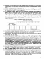
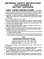
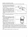
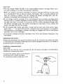
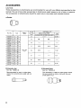
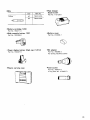
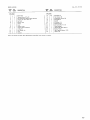
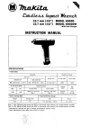
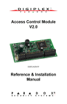
Cordless Impact Wrench
Equipped with Electric Brake
12.7 mm (1/2”)
MODEL 6911HD
12.7 mm (1/2”)
MODEL 6 9 1 l H D W
W i t h Fast Charger
12.7 mm (112”)
MODEL 691lHDWG
W i t h Fast Charger
INSTRUCTION MANUAL
Capacltles
Square drive
I
Standard bolt
M 8 - M 1 4 (5116’’ - 9/16’,)
Impact per minute
High tensile bolt
M6
-
M 1 2 1114”
-
0
12.7 mm ( 1 1 2 ” )
112”)
-
2.500
IRPMI
M a x . fastening torque
lSee note 1 below)
Dimens 10n s
IL x W x HI
Net weight
0 - 1,800
1 , 2 0 0 k g . c m 187 ft-lbSI
2 2 1 mm x 7 9 mm x 2 3 0 mm
18-314” x 3-118’’ x 9 ” )
1.8 k g 14.0 Ibs)
No load Speed
~
Voltage
12
v
I
I
Input
AConlv50Hz
60Hr
I
I
OUtDUt
D C 7 2 V - 1 2 V
I
I
Charqing time
1 Hr.
Note 1 . After fastening high tensile bolt M14 (F1 1T) for 8 seconds while using a fully charged battery cartridge.
2. Manufacturer reserves the right to change specifications without notice.
3. Specifications may differ from country to country.
WARNING: For your personal safety, READ and UNDERSTAND before using.
SAVE THESE INSTRUCTIONS FOR FUTURE REFERENCE.
IMPORTANT
SAFETY INSTRUCTIONS
(For All Tools)
WARNING: WHEN USING ELECTRIC TOOLS, BASIC SAFETY
PRECAUTIONS SHOULD ALWAYS BE FOLLOWED TO REDUCE
THE RISK OF FIRE, ELECTRIC SHOCK, AND PERSONAL
INJURY, INCLUDING THE FOLLOWING:
READ ALL INSTRUCTIONS.
1. KEEP WORK AREA CLEAN. Cluttered areas and benches invite injuries.
2. CONSIDER WORK AREA ENVIRONMENT. Don't use power tools in damp
or wet locations. Keep work area well lit. Don't expose power tools t o rain.
Don't use tool in presence of flammable liquids or gases.
3. KEEP CHILDREN AWAY. All visitors should be kept away from work area.
Don't let visitors contact tool or extension cord.
4.STORE IDLE TOOLS. When not in use, tools should be stored in dry, and high
or locked-up place - out of reach of children.
5. DON'T FORCE TOOL. It will do the job better and safer at the rate for which
it was intended.
6. USE RIGHT TOOL. Don't force small tool or attachment t o do the job of a
heavy-duty tool. Don't use tool for purpose not intended; for example, don't
use circular saw for cutting tree limbs or logs.
7 . DRESS PROPERLY. Don't wear loose clothing or jewelry. They can be caught
in moving parts. Rubber gloves and non-skid footwear are recommended
when working outdoors. Wear protective hair covering t o contain long hair.
8. USE SAFETY GLASSES. Also use face or dust mask if cutting operation is
dusty.
9. DON'T ABUSE CORD. Never carry tool by cord or yank it t o disconnect from
receptacle. Keep cord from heat, oil, and sharp edges.
IO. SECURE WORK. Use clamps or a vise t o hold work. It's safer than using
your hand and it frees both hands t o operate tool.
11. DON'T OVERREACH. Keep proper footing and balance at all times.
12. MAINTAIN TOOLS WITH CARE. Keep tools sharp and clean for better and
safer performance. Follow instructions for lubricating and changing accessories. Inspect tool cords periodically and if damaged, have repaired by authorized service facility. Inspect extension cords periodically and replace if
damaged. Keep handles dry, clean, and free from oil and grease.
13. DISCONNECT TOOLS. When not in use, before servicing, and when changing accessories, such as blades, bits, cutters.
2
14. REMOVE ADJUSTING KEYS AND WRENCHES. Form habit of checking t o
see that keys and adjusting wrenches are removed from tool before turning
it on.
15. AVOID UNINTENTIONAL STARTING. Don't carry tool with finger on switch.
Be sure switch is OFF when plugging in.
16. EXTENSION CORDS. Make sure your extension cord is in good condition.
When using an extension cord, be sure to use one heavy enough to carry
the current your product will draw. An undersized cord will cause a drop
in line voltage resulting in loss of power and overheating. Table 1 shows the
correct size to use depending on cord length and nameplate ampere rating.
If in doubt, use the next heavier gage. The smaller the gage number, the
heavier the cord.
TABLE 1 MINIMUM GAGE FOR CORD SETS
Total Length of Cord in Feet
0-225
I
26 - 50
Ampere Rating
More
Not More
Than
Than
0
6
-
10
12
-
-
6
10
12
16
I
51 - 100
I
101 - 150
A W G
18
18
16
14
16
16
16
12
;:
I
14
12
14
12
Not Recommended
3
VOLTAGE WARNING: Before connecting the tool to a power source (receptacle.
outlet, etc.) be sure the voltage supplied is the same as that specified on the
nameplate of the tool. A power source with voltage greater than that specified
for the tool can result in SERIOUS INJURY to the user - as well as damage to
the tool. If in doubt, DO NOT PLUG IN THE TOOL. Using a power source with
voltage less than the nameplate rating is harmful to the motor.
4
IMPORTANT SAFETY INSTRUCTIONS
FOR CHARGER &
BATTERY CARTRIDGE
SAVE THESE INSTRUCTIONS
- This manual
contains important safety and operating instructions for battery charger.
2.Before using battery charger, read all instructions and cautionary markings
on (1) battery charger, (21battery, and (3)product using battery.
3.CAUTION - To reduce risk of injury, charge only MAKITA Battery Cartridge
1200 & 1201.Other types of batteries may burst causing personal injury
and damage.
4. Do not expose charger to rain or snow.
5. Use of an attachment not recommended or sold by the battery charger
manufacturer may result in a risk of fire, electric shock, or injury t o persons.
6. To reduce risk of damage to electric plug and cord, pull by plug rather than
cord when disconnecting charger.
7. Make sure cord is located so that it will not be stepped on, tripped over, or
otherwise subjected to damage or stress.
8.An extension cord should not be used unless absolutely necessary. Use of
improper extension cord could result in a risk of fire and electric shock. If
extension cord must be used, make sure:
a. That pins on plug of extension cord are the same number, size, and shape
as those of plug on charger;
b. That extension cord is properly wired and in good electrical condition; and
c. That wire size is at least as large as the one specified in the table below.
I.
TABLE 1
RECOMMENDED MINIMUM AWG SIZE FOR
EXTENSION CORDS FOR BATTERY CHARGERS
Length of Cord (Feet)
AWG Size of Cord
25
18
50
18
100
18
150
16
5
ADDITIONAL SAFETY RULES
FOR CHARGER & BATTERY CARTRIDGE
1. Do not charge Battery Cartridge when temperature is BELOW 10°C (50OF)
or ABOVE 4OoC (104OF).
2. Do not attempt to use a step-up transformer, an engine generator or DC power
receptacle.
3. Do not allow anything t o cover or clog the charger vents.
4. Always cover the battery terminals with the battery cover when the battery
cartridge is not used.
5. A battery short can cause a large current flow, overheating, possible burns
and even a breakdown.
(1) Do not touch the terminals with any conductive material.
(2) Avoid storing battery cartridge in a container with other metal objects such
as nails, coins, etc.
(3)Do not expose battery cartridge t o water or rain.
6. Do not store the tool and Battery Cartridge in locations where the temperature may reach or exceed 5OoC (122OF).
7. Do not incinerate the Battery Cartridge even if it is severely damaged or is
completely worn out. The battery cartridge can explode in a fire.
ADDITIONAL SAFETY RULES
FOR CORDLESS IMPACT WRENCH
1. Be aware that this tool is always in an operating condition, because it does
not have t o be plugged into an electrical outlet.
2. Wear ear protectors.
3. Check the socket carefully for wear, cracks or damage before installation.
4. Hold the tool firmly.
5. Always be sure you have a firm footing.
Be sure no one is below when using the tool in high locations.
6. The proper fastening torque may differ depending upon the kind or size of
the bolt. Check the torque with a torque wrench.
7. When driving into walls, floors or wherever "live" electrical wires may be
encountered, DO NOT TOUCH ANY METAL PARTS OF THE TOOL!
Hold the tool only by the insulated grasping surfaces t o prevent electric shock
if you drive into a "live" wire.
SAVE THESE INSTRUCTIONS.
6
* T o remove the battery cartridge, pull out
the set plate on the tool and grasp both
sides of the cartridge while withdrawing
it from the tool.
*To insert the battery cartridge, align the
tongue on the battery cartridge with the
groove in the housing and slip it into
place. Snap the set plate back into place.
Be sure to close the set plate fully before
using the tool to prevent the battery
cartridge from accidentally falling out of
the tool.
Set 'late
B a t t e r y cartridge
*Do not use force when inserting the battery cartridge. If the cartridge does not slide in
easily, it is not being inserted correctly.
Charging
Your new battery cartridge i s not charged.
You will need to charge it before use. Use
the fast charger Model DC1201 to charge
the battery cartridge.
*Plug the fast charger into the proper A/C
voltage source. The charging light will
flash in green color.
*Insert the battery cartridge so that the
plus and minus terminals on the battery
cartridge are on the same sides as their
respective markings on the fast charger.
Insert the cartridge fully into the port so that it rests on the charger port floor.
*When the battery cartridge is inserted, the charging light color will charge from green to
red and charging will begin. The charging light will remian lit steadily during charging.
*When charging is completed, the charging light color will change from red t o green and
a tone will sound steadily for about 5 seconds. The charging time is approximately one
hour.
*After charging, unplug the charger from the power source.
7
CAUTION :
*The fast charger Model DC1201 is for charging Makita battery cartridge. Never use it
for other purposes or for other manufacturer’s batteries.
*When you charge a new battery cartridge or a battery cartridge which has not been used
for a long period of time, it may not accept a full charge. This is a normal condition and
does not indicate a problem. You can recharge the battery cartridge fully after discharging it completely and recharging a couple of times.
If you charge a battery cartridge from a just-operated tool or a battery cartridge which
has been left in a location exposed t o direct sunlight or heat for a long time, the charging light may flash in red color. If this occurs, wait for a while. Charging will begin after
the battery cartridge cools. The battery cartridge will cool faster if you remove the
battery cartridge from the fast charger.
If the charging light flashes alternately in green and red color and a tone sounds “beep,
beep, beep, . .” for about 20 seconds, a problem exists and charging is not possible.
The terminals on the charger or battery cartridge are clogged with dust or the battery
cartridge i s worn out or damaged.
0 If you wish to charge two battery cartridges, allow 15 minutes between chargings on the
fast charger.
.
Selecting correct socket
Always use the correct size socket for bolts and nuts. An incorrect size socket will result
i n inaccurate and inconsistent fastening torque and/or damage to the bolt or nut. Refer to
accessories section for socket size.
Installing or removing socket
CAUTION ;
Always be sure that the tool is switched off and the battery cartridge i s removed before
installing or removing the socket.
To instal the socket, push it onto the anvil
of the tool until it locks into place.
To remove the socket, simply pull it off.
8
Socket
Switch action
Tool speed is increased by increasing pressure on the trigger. To start the tool,
simply pull the trigger Release the trigger
t o stop.
S w i t i h trigger
I ',
'\
CAUTION :
Before inserting the battery cartridge into the tool, always check to see that the switch
trigger actuates properly and returns t o the "OFF" position when released.
Reversing switch action
This tool has a reversing switch t o change
the direction of rotation. Move the reversing switch t o the left for clockwise rotation or t o the right for counterclockwise.
CATU ION :
0Alwasy check the direction of rotation before operation.
.Use the reversing switch only after the tool comes t o a complete stop. Changing the
direction of rotation before the tool stops may damage the tool.
9
Operation
The proper fastening torque may differ depending upon the kind or size of the bolt. The
relation between fastening torque and fastening time is shown in the figures below.
Standard bolt
ko . cm
Ifi.Ibs)
1000
(721
M12 x 4 5 1112” x 1-25/32”)
1
-/
M14 x 4 5 (9/16” x 1-25/32”)
Proper fastening torque
for M14 ( 9 / 1 6 ’ l
OI
::
IL“
Proper fastening
M10 X 45 (31%’ x 1-25/32”)
400
for M12 (112”)
(29)
Proper fastening torque
for M10 ( 3 / 8 ’ )
O
L1
2
3
4
Seconds
Fastening time
200
(141
0
10
for M8 15/16”)
I
I
I
I
8
1
Hold the tool firmly and place the socket over the bot or nut. Turn the tool on and
fasten for the proper fastening time.
NOTE :
0 Hold the tool pointed straight a t the bolt or nut without applying excessive pressure on
the tool.
*Excessive fastening torque may damage the bolt or nut. Before starting your job, always
perform a t e s t operation to verify the adequate fastening speed and time for your bolt
or nut.
The fastening torque is affected by a wide variety of factors including the following.
After fastening, always check the torque with a torque wrench.
1. When the battery cartridge i s discharged almost completely, voltage will drop and
the fastening torque will be reduced.
2. Socket
*Failure t o use the correct size socket will cause a reduction in the fastening torque.
* A worn socket (wear on the hex end or square end) will cause a reduction in the
fastening torque.
3. Bolt
*Even though the torque coefficient and the class of bolt are the same, the proper
fastening torque will differ according t o the diameter of the bolt.
*Even though the diameters of bolts are the same, the proper fastening torque will
differ according t o the torque coefficient, the class of bolt and the bolt length.
4. The use of universal joint or the extension bar somewhat reduces the fastening force
of the impact wrench. Compensate by fastening for a longer period of time.
5. The type of materials t o be fastened, the manner of holding the tool and the tool
speed will affect the torque.
CAUTION :
If the tool is operated continuously until the battery cartridge has discharged, allow the
tool to rest for 15 minutes before proceeding with a fresh battery.
MAINTENANCE
CAUTION:
Always be sure that the tool is switched off and the battery cartridge is removed
before attempting t o perform inspection or maintenance.
To maintain product SAFETY and RELIABILITY, repairs, maintenance or adjustment
should be performed by Makita Authorized or Factory Service Centers, always using
Makita replacement parts.
11
ACCESSORIES
CAUTION:
These accessories or attachments are recommended for use with your Makita tool specified in this
manual. The use of any other accessories or attachments might present a risk of injury to persons.
The accessories or attachments should be used only in the proper and intended manner.
Socket
133216-3
22-42
133217-1
133218-9
133219-7
22 - 52
23 - 43
2 3 - 52
22
M14
M12
-
23
-
-
9/16'
Extension bar
Universal joint
Part No. 785201-8
Part No. 785205-0
Recommended for work in tight place
where the conventional socket will not
reach.
This accessory is useful in tight spaces where
the tool cannot be held in line w i t h the axis
of the bolt or nut.
12
Bits
Fast charger
Size
Part No.
Model DC1201
Part No. 1 131 26-0
Phillips
Battery cartridge 1 2 0 0
Part No. 192271-4
High capacity battery 1 2 0 1
Battery cover
Part No. 192296-8
Part No. 414938-7
*Power display battery (High cap.) 1201A
Bit adapter
Part No. 192407-5
Part No. 785069-2
For driving machine screws
Plastic carrying case
Oval socket
Part No. 785401-0
0 ring (Part No. 213405-7)
13
Apr-O5-'93
EN
CORDLESS IMPACT WRENCH
Model 6911HD
Note: The switch and other part configurations
may differ from country to country.
14
Apr-O5-'93
MODEL 6911HD
$tD
$cD
DESCRIPTION
M
:i'
EN
DESCRIPTION
~
~
1
2
3
4
1
6
1
1
5
1
6
1
I
8
9
10
11
12
13
14
1
1
1
4
1
1
1
1
Name Plate
Tapping Screw 0 1 4 x 2 0
Pan Head Screw M4x20 [With Washer1
Housing Set lWith llem 241
set Plate
Switch Lever
Switch
Lever
Hammer Care
Tapping Screw MT4x2O
0 Ring 50
Flaf Washer 18
Anvil
15
16
17
18
19
20
21
22
23
24
26
21
28
29
1
1
2
1
1
1
1
1
1
1
1
1
Steel Ball 3 5
Flaf Washer 28
Compression Spring 30
Steel Ball 5 6
Spindle
DC Motor 12 V
Plane B e a m 9 4
Gear Complete 10-38
Plane Beallng 4
Housing Set [With Item 41
Battery Holder
High Capacity Battery 1201
Hand Strap
H.3"W
Note The Switch and other par¶ specifications may differ from country to country
15
Recycling the Battery
The only way to dispose of a Makita battery is
to recycle it. The law prohibits any other
method of disposal.
1
Ni-Cd
I
To recycle the battery:
1. Remove the battery from the tool.
2. a). Take the battery to your nearest Makita Factory Service Center
or
b). Take the battery to your nearest Makita Authorized Service Center or
Distributor that has been designated as a Makita battery recycling location.
Call your nearest Makita Service Center or Distributor to determine the location
that provides Makita battery recycling. See your local Yellow Pages under
’’Tools-Electric’:
MAKlTA LIMITED ONE YEAR WARRANTY
Warranty Policy
Every Makita tool is thoroughly inspected and tested before leaving the factory. It is warranted t o
be free of defects from workmanship and materials for the period of ONE YEAR from the date of
original purchase. Should any trouble develop during this one-year period return the COMPLETE
tool. freight prepaid, t o one of Makita’s Factory or Authocized Sewice Cer&
If inspectlo” shows
the trouble IS caused by defective workmanship or material, Makita will repur (or at our option,
replace) without charge.
This Warranty does not apply where:
repairs have been made or attempted by others.
repairs are required because of normal we- and tear:
The tool has been abused, misused or improperly maintained:
alterations have been made to the tool.
IN NO EVENT SHALL MAKITA BE LIABLE FOR ANY INDIRECT INCIDENTAL OR CONSEQUENTIALDAMAGES FROM THE SALE OR USE OF THE P R O D ~ C TTHIS
.
DISCLAIMER
APPLIES BOTH DURING AND AFTER THE TERM OF THIS WARRANTY.
MAKITA DISCLAIMS LIABILITY FOR ANY IMPLIED WARRANTIES, INCLUDING IMPLIED
WARRANTIES O F “MERCHANTABILITY” AND “FITNESS FOR A SPECIFIC PURPOSE,
AFTER THE ONE-YEAR TERM O F THIS WARRANTY.
This Warranty gives you specific legal rights, and you may also have other rights which vary from
state t o state. Some stales do not allow the excluslon or limitation of incidental or consequential
damages, so the above limitation or exclusion may not apply t o you. Some states do not allow
limitation on how long an implied warranty lasts, so the above limitation may not apply to you.
Makita Corporation
3-11-8, Sumiyoshi-cho,
Anjo, Aichi 446 Japan
883903 - 063
PRINTED IN JAPAN
1994-9-N