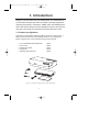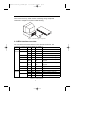
1
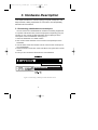
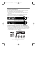
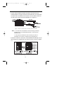
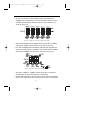
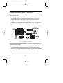
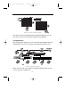
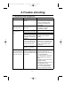
update ALH-316_324UM.qxd
11/10/99 8:42 AM
›¶›– 1
ALH-316ds/324ds
Acer Ethernet Hub
16/24-port 10/100 Mbps Ethernet Hub
User's Guide
update ALH-316_324UM.qxd
11/10/99 8:42 AM
›¶›– I
Copyright
Copyright © 1999 by this company and all rights reserved. No part of this
publication may be reproduced, transmitted, transcribed, stored in a
retrieval system, or translated into any language or computer language, in
any form or by any means, electronic, mechanical, magnetic, optical,
chemical, manual or otherwise, without the prior written permission of this
company.
Disclaimer
Acer Netxus Inc. reserves the right to revise this publication and to make
changes from time to time in the contents hereof without obligation to
notify any person of such revision or changes.
Brand and product names are trademarks and/or registered trademarks of their
respective companies.
I
update ALH-316_324UM.qxd
11/10/99 8:42 AM
›¶›– II
Table of Contents
1.
2.
3.
4.
5.
Introduction............................................................. 1
Hardware Installation.............................................. 2
Hardware Description............................................. 8
Trouble shooting..................................................... 14
Specification........................................................... 15
II
update ALH-316_324UM.qxd
11/10/99 8:42 AM
›¶›– 1
1. Introduction
Thanks for your purchase of the ALH-316ds/324ds. ALH-316ds/324ds is
an 16/24-port dual speed hub works as terminal connecting equipment in
corporate environment to combine the 10Mbps users and 100Mbps power
users. With its auto-sensing and auto-negotiation functions, all you have to
do is plug in and check the correctness of the LEDs and start to work.
1.1 Product configuration
The product configuration inside the package is shown in the Figure 1-1.
Please check the contents of the package if there is any missing part
before using the hub. The accessories of this product include:
•
•
•
•
•
ALH-316ds/324ds dual speed hub
Power cord
Hangers and pads
User guide
Stacking cable (SCSI-II)
1 piece
1 piece
1 pack
1 book
1 piece
Figure 1-1 Product configuration of ALH-316ds/324ds
1
update ALH-316_324UM.qxd
11/10/99 8:42 AM
›¶›– 2
2. Hardware Installation
This chapter will guide you through how to install the ALH-316ds/324ds. It
includes procedures for installing the hub on your working surface,
connecting the hub to your computer, and guidelines to see if it works well.
Before setting up your hub, please take note of the front and rear panel of
this hub, as shown in Figure 2-1 and 2-2.
Figure 2-1 Front panel
Figure 2-2 Rear Panel
Before installing the hub, you have to find a solid working surface to place
the hub and make sure the equipment is not close to any high voltage
power source or over-heated sources. Also keep away from electronic
equipment sensitive to electronic interface. The brief procedures of
installing your hub should be as following section:
2
update ALH-316_324UM.qxd
11/10/99 8:42 AM
›¶›– 3
2.1 Connecting power cord
Carefully unpack the ALH-316ds/324ds and it’s accessories. For the first
time that you use this hub, please make sure there is all the same as the
checking list in the package. The procedure for connecting to the power
will be:
1. Place the hub on the desktop or one a rack stably and verify the
power cord is a correct one suitable for your national standard plugs.
2. Connect the power cord to the hub first
3. Plug the power cord into the outlet on the wall, turn on the power,
and check if the power LED lights up. If it lights up, then the hub is
ready to be connected to the network. See Figure 2-3.
Figure 2-3 Connecting to the power
2.2 Connecting to computers
Make sure the hub is ready for networking by checking if the PWR
indicator displays.
1. Shut down the computer and install an adapter card in.
2. Plug in the one end of UTP/STP cable to the RJ-45 phone jack of the
network adapter.
3. Plug the other end of UTP/STP to normal ports of the ALH316d/ALH-324ds.
4.Turn on the PC and check if the Link LEDs on the adapter card and
the hub (Named as Link/REC) are lit up. See Figure 2-4
3
update ALH-316_324UM.qxd
11/10/99 8:42 AM
›¶›– 4
If the LED is not lit up, there must be something wrong and please
reference to Chapter 4 for quick trouble shooting.
Figure 2-4 Connecting to computers
2.3 LEDs interface overview
You can observe the LEDs status to see if the hub works fine. The
meanings of LEDs are summarized as Table 2-1.
LEDs
System
Power
Indicators FAN Err.
Color
Blink Indication
Green
Power on
Power is on and works normally.
Yellow Blink Fan Error
Fan inside is work abnormal.
Yellow
Fan Fail
Fan inside is fail.
10 Collision
Collision in 10 Mbps segment
10 Collision Yellow
100 Collision Yellow
100 Collision Collision in 100 Mbps segment
10 Utilization Green/
Utilization
Utilization ratio in 10 Mbps
ratio
segment
Utilization
Utilization ratio in 100 Mbps
segment
Yellow
100 Utilization Green/
Port
Description
Yellow
ratio
Master
Green
Master
Bridge function disabled 8/12
Slave
Green
Slave
Bridge function enabled 8/12
Link/REC
Green
Link
Port is linked.
Indicators
100
Green Blink Receiving
Receiving data in this port
Green
100 Mbps
Run in 100 Mbps
Dark
10 Mbps
Run in 10 Mbps
Table 2-1 LEDs definition
4
update ALH-316_324UM.qxd
11/10/99 8:42 AM
›¶›– 5
2.3.1 System indicators
PWR: When the power is connected rightly, the PWR LED will be lit on
Green.
If the LED is not lit on, then you should check the connection of your power
and the outlet of power.
Fan Err.: When the fan malfunction at work, then the Fan Err LED will be
lit up and blink. And when the fan is fail, the LED will be lit without blinking.
You should check you fan and your vender and have a new fan to instead
of the old one to make sure the equipment will work normally.
10 Collision & 100 Collision: If there’s any collision happened in 10 Mbps
or 100 Mbps domain, then the 10 Collision or 100 Collision LEDs will be lit up.
Master: When the system is master hub, the Master LED will be lit on Green.
Slave: When the system is slave hub, the Slave LED will be lit on green.
2.3.2 Port indicators
100: When the port is linked with 100 Mbps equipment, the LED will be lit
on GREEN. Linking with 10 Mbps one, it will be dark.
Link/REC: When the port is linked, the Link/REC will be lit on GREEN.
And when there’s any data received in the port, the LED will be blinking in
GREEN. If the port is linked, and the LED isn’t lit up, please check if the
port connector fasten tightly.
5
update ALH-316_324UM.qxd
11/10/99 8:42 AM
›¶›– 6
2.3.3 Network utilization indicators
There are 2 sets of LED indicators to indicate the real-time network
utilization of 10 Mbps and 100 Mbps domain.
10M
Speed
10Mbps
100M
100Mbps
Color
Green
Yellow
Green
Yellow
Utilization
5, 15, 25
35, 55+
5, 15, 25
35, 55+
Figure 2-5 Network utilization indicators
The number of utilization is in percentage. For example, “15” of “100M”
means 15% of 100 Mbps, “55+” of “10M” means the utilization is more than
55% of 10Mbps.
6
update ALH-316_324UM.qxd
11/10/99 8:42 AM
›¶›– 7
2.4 Rack mounting
To install the ALH-316ds/324ds hub in a 19-inch rack, please follow these steps:
1. If the hub has rubber footpads on the bottom of the unit, please
remove them.
2. Locate the rack mounting holes on both sides of the hub
(see Figure 2- 6).
3. Using a cross-head screwdriver, attach the two mounting brackets to
both sides of the hub with the four screws supplied with the unit
(see Figure 2- 6).
4. Place the hub in the rack and align the holes in the mounting bracket
with the holes in the rack chassis (see Figure 2- 7).
5. Insert two mounting screws (the rack-mount equipment should provide
these screws), into each of the mounting brackets and tighten with a
suitable screwdriver.
Figure 2-6: Attaching mounting brackets (8 screws: M3x5)
Figure 2-7: Attaching mounting brackets for a rack mount (4 screws: M5x10)
Note: The pannel wall should be able to bear three times of the system's
weight
7
update ALH-316_324UM.qxd
11/10/99 8:42 AM
›¶›– 8
3. Hardware Description
This chapter describes the network topology for hybrid 10 Mbps and 100
Mbps networks, cabling requirement for connections, the interoperability
between hubs and switches.
3.1 Connecting a hub/switch to normal port
You can use the ALH-316ds/324ds as a terminal connecting equipments
in corporate LAN environment, and for the purpose of expanding your port
number you can connect another hub/switch with it’s uplink port to the
normal port of ALH-316ds/324ds. See Figure 3-1
1. Place the hub/switch on a stable surface.
2. Use one end of the UTP/STP cord to connect to the uplink port of the
hub/switch.
3. Use the other end of the UTP/STP cord to connect to the normal port of
ALH-316ds/324ds
4. Check the status of Link LED. If the Link LED is lit on green then it works
normal.
5. Then you can connect the terminal to the new hub/switch
HUB
Figure 3-1 Connecting to normal port with other hub/switch
8
update ALH-316_324UM.qxd
11/10/99 8:42 AM
›¶›– 9
3.2 How to use up-link port
With up-link port you can use it to cascade to another switch to expand
your network. Please refer to the following procedure.
1. Use one end of UTP to connect to the 16th /24th up-link port of ALH316ds/324ds
2. Use the other end to connect to the normal port of the new switch
3. Make sure the Link LED is lit then it will work normally.
Normal hub port
Master
Bridge port (10/100Mbps full/duplex)
Bridge port (10/100Mbps half/duplex)
Slave
Bridge port (10/100Mbps full/duplex)
3.3 Network topology for AcerHub ALH-316ds/324ds
The factors for ALH-316ds/324ds dual-speed network implementation are:
• For stand-alone one, the ALH-316ds/324ds consists of separate 10Mbps
and 100Mbps network domains with one built-in switch to inter-connect
the data in domains, as shown in Figure 3-2.
316ds/324ds
Figure 3-2 Separate domains in ALH-316ds/324ds.
9
update ALH-316_324UM.qxd
11/10/99 8:42 AM
›¶›– 10
• The hub will be divided into Master and Slave hubs when they are
stacked together. The upper most hub is the Master hub, and other hubs
are Slave hubs. The Master hub continues to use the built-in switch but
the switch in the Slave hubs will be disabled, as in Figure 3-3.
Figure 3-3 Master and Slave hubs in stacking ALH-316ds/324ds.
Note: 1. To concern the convenience of the cross-wiring connection
between hubs, ALH-316ds/324ds provide 1 cross-over port
(marked as"X").
2. The up-link port utilizes the first connection port with "X"
sign.When you connect to another hub by this uplink port.
• The built-in switches in slave hubs will be disabled automatically to avoid
data looping from multiple inter-connections of hubs, as shown in Figure
3-4.
Figure 3-4 Auto Data looping prevention in ALH-316ds/324ds.
10
update ALH-316_324UM.qxd
11/10/99 8:42 AM
›¶›– 11
• By way of an uplink port with a Bridge function, the limitations on
100Mbps hub count(maximum 2) can be eliminated. The hub count is
unlimited and cable length between hubs can reach 100meters, as
shown in Figure 3-5.
Figure 3-5Unlimited cascading of ALH-316ds/324ds.
• All PCs with 10Mbps network adapter cards transmit data at 10Mbps
and form the 10Mbps network domain, as shown in Figure 3-6.
• PCs with 10/100Mbps network adapter cards will auto-negotiate and
switch the network speed to 100Mbps. They transmit data at 100Mbps
and form the 100Mbps network domain, as shown in Figure 3-6.
Figure 3-6 Network domains and bridged uplink.
• The data in 10Mbps or 100Mbps domain will be inter-connected by
internal built-in switch in the Master hub consequently.
• All hubs delivering data by the shared-bus always work on half-duplex
mode; that is, data can be sent or received at one time in one direction.
11
update ALH-316_324UM.qxd
11/10/99 8:42 AM
›¶›– 12
3.4 Interconnection to Hubs and Switches
3.4.1 Connecting to Ethernet Hubs : The factors governing hub
interconnection are:
• The hubs are only connected by uplink port. ALH-316ds/324ds will
automatically transmit at 10Mbps network speed when connecting to
10Mbps Ethernet hubs and 100Mbps network speed if connected to
100Mbps hubs.
• If multiple ALH-316ds/324ds are stacked together, users can connect to
hubs by the bridge uplink port in master/slave hubs. , as shown in Figure
3-7.
Figure 3-7 Connect to Ethernet Hubs.
3.4.2 Connecting to Ethernet Switches : The factors governing hub and
switch interconnection are:
• The hubs are only connected to Ethernet switches by an uplink port.
ALH-316ds/324ds will automatically work at 100Mbps network speed
when connected to 10/100Mbps Ethernet switching ports and it will work
at 10Mbps network speed if connected to 10Mbps switching ports.
12
update ALH-316_324UM.qxd
11/10/99 8:42 AM
›¶›– 13
Figure 3-8 Connect to Ethernet Switches.
No matter if the ALH-316ds/324ds hubs are stacked together or not, the
user always can connect to Ethernet switches by the uplink port.
3.5 Application
With this application diagram, you can clearly see the possibility what ALH316ds/324ds can do for you in expand your network. (See Figure 3-9)
Figure 3-9 Application diagram
Notice: Use UTP Cat. 5 to connect to 100 Mbps equipment and UTP Cat.
3,4,5 to connect to 10 Mbps one.
13
update ALH-316_324UM.qxd
11/10/99 8:42 AM
›¶›– 14
4.Trouble shooting
4.1 Symptoms and Suggestions
Symptoms
All LEDs are off.
Possible Reason
The hub is not receiving
power.
Fan Err. LED is
blinking or down
The fan is dead or works
abnormal
Link LED of a
connected port
is off.
1.The UTP cable is
not securely connected
2.The port is bad
3.If the other party is a
PC, the network interface
card(NIC) could be not
working
4.If the other party is a
hub or LAN switch, the
connected ports signal
could be cross-over
100 LED is not lit
when connected to a
100 NIC or 100 Hub
(but Link LED is lit.)
5.The UTP cable is
broken, or it is crossovered cable.
The auto-negotiation
function is failed between
ALH-316ds/324ds and the
other part
14
Suggestion
1.Check if the AC power cord
plug is both securely fastened at
the AC outlet and the hubs.
2.Contact you vender if still
unworkable.
1.Check your fan, maybe you
should have a new fan.
2.Contact the vender
1.Check the cable connection
2 Try to connect another port
3.Check if the network interface
card (NIC) were installed
properly.
4.Make sure ALH-316ds/324ds
normal port is connected to the
other hub’s (or switch’s) uplink
port is connected the other’s
normal port.
5.Try another normal cable.
1. Check if you force the
connection equipment in
specific mode. If, yes, then free
it to auto-negotiation
2. Un-plug the UTP cable from
ALH-316ds/324ds and plug-in
again.
3.Check if the NIC is set to autonegotiation mode.
4.Check if the other hub is set to
auto-negotiation mode
5. If the above steps does not
work, it is an interoperability
problem, contact your vender.
update ALH-316_324UM.qxd
11/10/99 8:42 AM
›¶›– 15
5. Specifications
Specification:
Comply with IEEE 802.3 /802.3u repeater standards
- 16/24-port 10Base-T/100Base-TX RJ-45 phone jack ports
- 1-port Uplink 10Base-T/100Base-TX RJ-45 phone jack port
LEDs indicators: Power, Fan err., Collision, Utilization, Link/Receive,
10/100Mbps.
Power supply: Internal switching power supply: 100~240V AC, 50~60 Hz.
The power receptacle connects a power supply cord with the following
specifications:
CSA and UL Listed, No. 18. AWG minimum type SVT or better in
mechanical serviceability. Terminated in a moulded-pm NEMA type 5-15 or
6-15P(for 120VAC or 250VAC respectively); or male attachment cap at one
end, the other end terminates in a moulded-on IEC-type CEE-22 female
connector body.
Dimension:
Environment:
Standards 19 inches rack mount size
Temperature: 0~50°C
Humidity: 20~80% non-condensing
Cabling requirement:
EMI:
UTP Category 3,4,5 for 10Base-T
UTP Category 5 for 100Base-TX
FCC Class A, CE A, VCCI A, C-tick A
15
update ALH-316_324UM.qxd
11/10/99 8:42 AM
›¶›– 16
Product Limited Warranty
Acer Netxus Incorporated (ANI) warrants its product to be free from defects in
materials and workmanship, under normal use and service, for the following lengths of
time from the date of purchase from ANI or its Authorized Resellers.
Network adapter card
Unmanaged hub
Dual-speed hub
Switch and managed hub
Limited Lifetime
*Limited Lifetime
*3 year
*3 year
* Power supply/adapter and fans in these devices covered by ONE YEAR warranty
All products with limited lifetime warranty have a standard five-year warranty. This
warranty does not cover the product if it is damaged by abuse, accident, misuse,
improper installation, or improper testing. If a product does not operate as warranted
during the applicable warranty period, ANI shall, at its option and expense, either repair
the defective product or part returned to ANI, or deliver to customer an equivalent
product or part to replace the defective item. All products that are replaced will become
the property of ANI. Replacement products may be new or reconditioned. Any
replacement or repaired product or part shall be covered by warranty for ninety days,or
for the remainder of the initial warranty period, whichever is longer. ANI shall not be
responsible for any software, firmware, information, or memory data of customer
contained in, stored on, or integrated with any products returned to ANI pursuant to any
warranty. Before you obtain warranty service, you must request an RMA (Return
Materials Authorization) number by calling, faxing or writing ANI’s Customer Service
Department at the numbers listed below. You must use the original container (or the
equivalent) and pay the shipping charge.
ANI SHALL NOT BE HELD LIABLE FOR INCIDENTAL, CONSEQUENTIAL, INDIRECT,
SPECIAL OR RUNTIME DAMAGES OF ANY KIND; OR FOR LOSS OF REVENUE,
LOSS OF BUSINESS, OR OTHER FINANCIAL LOSS ARISING OUT OF OR IN
CONNECTION WITH THE SALE, INSTALLATION, MAINTENANCE, USE,
PERFORMANCE, FAILURE, OR INTERRUPTION OF ITS PRODUCTS, EVEN IF ANI
OR ITS AUTHORIZED DEALER HAS BEEN ADVISED OF THE POSSIBILITY OF
SUCH DAMAGES.
If you purchased this product in the UNITED STATES, some states do not allow the
limitation or exclusion of liability for incidental consequential damages, so the above
limitation may not apply to you.
Model Name
Series No. (S/N)
Purchase Date
( Authorized distributors' or Resellers' Stamp )
16
/
/
update ALH-316_324UM.qxd
11/10/99 8:42 AM
›¶›– 17
If you purchased this product in the UNITED STATES, some states do not allow the limitation or
exclusion of liability for incidental consequential damages, so the above limitation may not apply
to you.
Contact us:
Acer Computer International Ltd.
Acer UK Limited
Taiwan Branch
Tel: 886-2-2696 0123 ext.3130
Fax: 886-2-8691 2316
http://www.aci.acer.com.tw
Tel: 44-1628-533422
Fax: 44-1628-524071
http://www.aceruk.co.uk
Acer Computer France S.A.R.L.
Acer America Corporation
Tel: 33-1-4817 4040
Fax: 33-1-4817 4089
Tel: 1-408-433 3678
Fax:1-408-922 2940
http://www.acer.com/aac
Distribution/Information
Hotline: 1-800-369 6736
Fax: 1-408-432 0496
http://www.acer.com/aac/aod
Acer Computer GmbH
Tel: 49-4102-488-0
Fax: 49-4102-488-101
Dealers' Information
Hotline: Germany 0180-3234781
End users' Information
Hotline: Germany 0180-5009898
Acer Latin America Inc.
Tel: 1-305-392 7270
Fax:1-305-392 7216
Acer Computer Iberica, S.A.
Tel: 34-3-499-0303
Fax: 34-3-499-0483
Acer Japan Corporation
Tel: 81-4-8290 1819
Fax: 81-4-8290 1820
Acer Italy/Texas Instruments
Acer Computer B.V.
Tel: 39-2-2692-2565
Fax: 39-2-2692-1021
Tel: 31-73-645 9645
Fax: 31-73-645 9599
17
update ALH-316_324UM.qxd
11/10/99 8:42 AM
›¶›– 18
100% Recyclable Paper
P/N 49.22018.202
Acer Netxus Inc.
A Communications Company of Acer