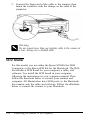
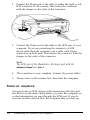
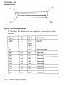
1
EPSON
®
User’s Guide
4001572
CO1-00
FCC COMPLIANCE STATEMENT
FOR AMERICAN USERS
This equipment has been tested and found to comply With the limits for a class B
digital device, pursuant to Part 15 of the FCC Rules. These limits are designed to
provide reasonable protection against harmful interference in a residential installation.
This equipment generates, uses and can radiate radio frequency energy and, if not
installed and used in accordance with the instructions, may cause harmful interference
to radio or television reception. However, there is no guarantee that interference will
not occur in a particular installation. If this equipment does cause interference to radio
and television reception which can be determined by turning the equipment off and
on, the user is encouraged to try to correct the interference by one or more of the
following measures:
Reorient or relocate the receiving antenna
Increase the separation between the equipment and receiver
0 Connect the equipment into an outlet on a circuit different from that to which the
receiver is connected
a Consult the dealer or an experienced radio/TV technician for help.
WARNING
The connection of a non-shielded equipment interface cable to this equipment will
invalidate the FCC Certification of this device and may cause interference levels which
exceed the limits established by the FCC for this equipment. It is the responsibility of
the user to obtain and use a shielded equipment interface cable with this device. If this
equipment has more than one interface connector, do not leave cables connected to
unused interfaces.
Changes or modifications not expressly approved by Epson America, Inc., could void
the user’s authority to operate the equipment.
FOR CANADIAN USERS
This digital apparatus does not exceed the Class B limits for radio noise emissions from
digital apparatus as set out in the radio interference regulations of the Canadian
Department of Communications.
Le present appareil numérique n’émet pas de bruits radioéctriques dépassant les
limites applicables aux appareils numériques de Classe B prescrites dans le réglement
SLU le brouillage radioélectrique édicté par le Ministère des Communications du
Canada.
®
EPSON
ES-600C Scanner
User’s Guide
About the Cover
The cover of this guide was composed entirely using computer
graphics software and an Epson scanner. The photographs were
scanned at 300 dpi image resolution. The completed layout was color
separated on an imagesetter and output to film at 2540 dpi with a
screen resolution of 133 lines per inch.
All rights reserved. No part of this publication may be reproduced, stored in a retrieval
system, or transmitted in any form or by any means, mechanical, photocopying, recording,
or otherwise, without the prior written permission of Seiko Epson Corporation. No patent
liability is assumed with respect to the use of the information contained herein. Neither is
any liability assumed for damages resulting from the use of the information contained
herein.
Neither Seiko Epson Corporation nor its affiliates shall be liable to the purchaser of this
product or third parties for damages, losses, costs, or expenses incurred by purchaser or
third parties as a result of: accident, misuse, or abuse of this product or unauthorized
modifications, repairs, or alterations to this product.
Seiko Epson Corporation and its affiliates shall not be liable against any damages or
problems arising from the use of any options or any consumable products other than those
designated as Original Epson Products or Epson Approved Products by Seiko Epson
Corporation.
Epson is a registered trademark of Seiko Epson Corporation
General Notice: Other product names used hereinare for identification purposes only and
may be trademarks of their respective companies.
Copyright © 1992 by Epson America, Inc.
Torrance, California
ii
Contents
Introduction
Options . . . . . . . . . . . . . . . . . . . . . . . . . . . . . . . .
How to Use This Manual . . . . . . . . . . . . . . . . . . . . . .
Warnings, Cautions, and Notes . . . . . . . . . . . . . . . . . .
Where to Get Help . . . . . . . . . . . . . . . . . . . . . . . . . .
Important Safety Instructions. . . . . . . . . . . . . . . . . . . .
1
2
2
3
4
Chapter 1 Setup
Choosing a place for the scanner . .
Removing the transportation screw .
Plugging in the scanner . . . . . . . .
Setting the DIP switches . . . . . . .
5 Self test . . . . . . . . . . . . . . . . .
6 Resetting the DIP switches . . . . . .
1
2
3
4
.
.
.
.
.
.
.
.
.
.
.
.
.
.
.
.
.
.
.
.
.
.
.
.
.
.
.
.
.
.
.
.
.
.
.
.
.
.
.
.
.
.
l-2
l-2
l-4
l-5
l-6
l-8
. . . . . . .
. . . . . . .
. . . . . . .
. . . . . . .
. . . . . . .
. . . . . . .
. . . . . . .
. . . . . . .
. . . . . . .
2-2
2-2
2-3
2-3
24
2-5
2-7
2-7
2-8
.
.
.
.
.
.
.
.
.
.
.
.
.
.
.
.
.
.
.
.
.
.
.
.
.
.
.
.
.
.
.
.
.
.
.
.
Chapter 2 Connecting the Scanner to the Computer
Using an Interface Kit . . . . . . . . . .
Interface types . . . . . . . . . . .
Parallel Interface Model . . . . . . . .
Connecting the parallel interface .
SCSI Model . . . . . . . . . . . . . . . .
SCSI connections . . . . . . . . . .
Terminator setting . . . . . . . . .
Connecting the SCSI . . . . . . . .
Power-on sequence . . . . . . . .
.
.
.
.
.
.
.
.
.
.
.
.
.
.
.
.
.
.
.
.
.
.
.
.
.
.
.
.
.
.
.
.
.
.
.
.
.
.
.
.
.
.
.
.
.
.
.
.
.
.
.
.
.
.
.
.
.
.
.
.
.
.
.
.
iii
Chapter 3 Scanner Basics
Placing a Document on the Scanner . . . . . . . . . . . . . . . .
Scanner Setting Guidelines . . . . . . . . . . . . . . . . . . . . .
d Image type or mode . . . . . . . . . . . . . . . . . . . . .
u/ Resolution. . . . . . . . . . . . . . . . . . . . . . . . . . .
d Size or scale . . . . . . . . . . . . . . . . . . . . . . . . . .
(/ Halftoning and dropout . . . . . . . . . . . . . . . . . . .
(/ Brightness . . . . . . . . . . . . . . . . . . . . . . . . . . .
ti Color correction . . . . . . . . . . . . . . . . . . . . . . .
d Gamma correction . . . . . . . . . . . . . . . . . . . . . .
(/ Cropping . . . . . . . . . . . . . . . . . . . . . . . . . . .
Judging Image Quality . . . . . . . . . . . . . . . . . . . . . . . .
Equipment . . . . . . . . . . . . . . . . . . . . . . . . . . . . . . .
RAM and hard disk size . . . . . . . . . . . . . . . . . . . .
Accelerator boards . . . . . . . . . . . . . . . . . . . . . . .
Video cards. . . . . . . . . . . . . . . . . . . . . . . . . . . .
Monitors . . . . . . . . . . . . . . . . . . . . . . . . . . . . .
File compression software . . . . . . . . . . . . . . . . . . .
3-2
3-4
3-5
3-6
3-10
3-10
3-10
3-11
3-11
3-11
3-11
3-12
3-12
3-12
3-12
3-13
3-13
Chapter 4 Troubleshooting and Maintenance
Problems and Solutions . . . . . . . .
Maintenance . . . . . . . . . . . . . . .
Replacing the fluorescent lamps .
Transporting the Scanner . . . . . . . .
iv
.
.
.
.
.
.
.
.
.
.
.
.
.
.
.
.
.
.
.
.
.
.
.
.
.
.
.
.
.
.
.
.
.
.
.
.
.
.
.
.
.
.
.
.
.
.
.
.
.
.
.
.
.
.
.
.
.
.
.
.
4-2
4-8
4-9
4-10
Chapter 5 Technical Specifications
Scanner Specifications . . . . .
Electrical Specifications . . . . .
Environmental Conditions . . .
Parallel Interface Specifications
Timing charts . . . . . . . .
SCSI Specifications . . . . . . .
Signal pin assignments . .
Initialization . . . . . . . . . . .
Default settings. . . . . . .
DIP Switches . . . . . . . . . . .
.
.
.
.
.
.
.
.
.
.
.
.
.
.
.
.
.
.
.
.
.
.
.
.
.
.
.
.
.
.
.
.
.
.
.
.
.
.
.
.
.
.
.
.
.
.
.
.
.
.
.
.
.
.
.
.
.
.
.
.
.
.
.
.
.
.
.
.
.
.
.
.
.
.
.
.
.
.
.
.
.
.
.
.
.
.
.
.
.
.
.
.
.
.
.
.
.
.
.
.
.
.
.
.
.
.
.
.
.
.
.
.
.
.
.
.
.
.
.
.
.
.
.
.
.
.
.
.
.
.
.
.
.
.
.
.
.
.
.
.
.
.
.
.
.
.
.
.
.
.
.
.
.
.
.
.
.
.
.
.
.
.
.
.
.
.
.
.
.
.
.
.
.
.
.
.
.
.
.
.
5-2
5-4
5-4
5-5
5-8
5-9
5-10
5-11
5-12
5-12
Scanner Functions . . . . . . . . . . . . . . . . . . . . . . . . . .
How the scanner works . . . . . . . . . . . . . . . . . . . .
Scanner settings . . . . . . . . . . . . . . . . . . . . . . . .
A-2
A-2
A-3
Appendix
Glossary
Index
Introduction
The Epson® ES-600C is a full-color flatbed image scanner with
an 8 1/2 x 11 inch (letter) size scanning area. It has the ability to
scan in color (24 bit) or gray-scale monochrome (8 bit), making
it ideal for virtually all uses, from simple drawings to complex
full-color illustrations.
The ES-600C comes in two models, one with a bidirectional
parallel interface and one with a SCSI (Small Computer System
Interface). This manual covers both models. For either model,
you need an optional Epson interface kit to connect the scanner
to your computer.
For the bidirectional interface model, use Epson’s
Bidirectional Parallel Interface Kit for DOS Computers
(BIDIDOS). For the SCSI model, use either Epson’s Interface Kit
for Macintosh® Computers (ESMAC) or Epson’s SCSI Kit for
DOS Computers (SCSIDOS), depending on which computer
you have.
Options
Automatic Document Feeder (B813011)
This option is designed primarily for optical character
recognition (OCR) scanning. With software that supports the
ES-600C and OCR, you can stack up to 50 pages in the
automatic document feeder and scan them automatically. You
can then use them in a word processing program just as if you
had typed them yourself.
Transparency Unit (8813021)
This option allows you to scan transparent materials, primarily
35mm slides and negatives, in 24-bit color.
Introduction 2
How to Use This Manual
Chapter 1 describes setting up your scanner. Be sure to read
this first. Chapter 2 tells how to use the interface kits to connect
the scanner to your computer. The basic information in
Chapter 3 helps you use your software and scanner, and
Chapter 4 contains troubleshooting, maintenance, and
transportation information. Chapter 5 and the Appendix
provide technical information. See the end of this guide for a
glossary of scanner terms and an index.
Warnings, Cautions, and Notes
Warnings
must be followed carefully to avoid damage to your scanner
and computer.
Cautions
should be followed carefully to ensure your scanner operates
correctly.
Notes
contain important information and useful tips on the operation of
your scanner.
2 Introduction
Where to Get Help
Epson America provides local customer support and service
through a nationwide network of authorized Epson dealers and
Service Centers.
Epson also provides the following support services through the
Epson Consumer Resource Center at (800) 92243911:
Assistance in locating your nearest Authorized Epson
Reseller or Service Center
Technical assistance with the installation, configuration,
and operation of Epson products
Epson technical information library fax service
Product literature with technical specifications on our
current and new products
Sales of supplies, parts, documentation, and accessories for
your Epson product
Customer Relations
User group locations.
Introduction 3
Important Safety Instructions
1.
Read all of these instructions.
2.
Follow all warnings and instructions marked on the scanner.
3.
Unplug this scanner from the wall outlet before cleaning. Use a
damp cloth for cleaning and do not use liquid or aerosol cleaners.
4.
Do not use this scanner near water.
5.
Do not place the scanner on an unstable cart, stand, or table
because it may fall, causing serious damage.
6.
Slots and openings in the cabinet and the back or bottom are
provided for ventilation; to ensure reliable operation and
protection from overheating, these openings must not be blocked
or covered. The openings should never be blocked by placing the
scanner on a bed, sofa, rug, or other similar surface. The scanner
should never be placed near or over a radiator or heat register,
and it should not be placed in a built-in installation unless
proper ventilation is provided.
7.
Use the type of power source indicated on the marking label. If
you are not sure of the type of power available, consult your
dealer or local power company.
8.
This product may be equipped with a 3-wire grounding-type
plug, a plug having a third (grounding) pin. This plug will only
fit into a grounding-type outlet. This is a safety feature. If you
are unable to insert the plug into the outlet, contact your
electrician to replace your obsolete outlet. Do not defeat the
purpose of the grounding-type plug.
9. Do not put your scanner where the cord will be walked on.
4 Introduction
10. If you use an extension cord, make sure that the total of the
ampere ratings on the products plugged into the extension cord
does not exceed the extension cord ampere rating. Also, make
sure that the total of all products plugged into the wall outlet
does not exceed 15 amperes.
11. Never push objects of any kind through cabinet slots as they may
touch dangerous voltage points or short out parts that could
result in a risk of fire or electric shock. Never spill liquid of any
kind on the scanner.
12. Except as specifically explained in the User’s Guide, do not
attempt to service this product yourself. Opening or removing
those covers that are marked “Do Not Remove” may expose you
to dangerous voltage points or other risks. Refer all servicing in
those compartments to service personnel.
13. Unplug this scanner from the wall outlet and refer servicing to
qualified service personnel under the following conditions:
A. When the power cord or plug is damaged or frayed.
B. If liquid has been spilled into it.
C. If it has been exposed to rain or water.
D. If it does not operate normally when the operating
instructions are followed. Adjust only those controls that are
covered by the operating instructions since improper
adjustment of other controls may result in damage and will
often require extensive work by a qualified technician to
restore the product to normal operation.
E. If it has been dropped or the cabinet has been damaged.
F. If it exhibits a distinct change in performance, indicating a
need for service.
Introduction 5
Chapter 1
Setup
Choosing a place for the scanner . . . . . . . . . . . . . . . 1-2
Removing the transportation screw . . . . . . . . . . . . . 1 -2
Plugging in the scanner . . . . . . . . . . . . . . . . . . . . .
1
Setting the DIP switches . . . . . . . . . . . . . . . . . . . .
l-5
Self test . . . . . . . . . . . . . . . . . . . . . . . . . . . . . .
l-6
Resetting the DIP switches . . . . . . . . . . . . . . . . . . .
l-8
-4
setup 1-1
1Choosing a place for the scanner
You should consider the following when selecting a location for
your scanner:
P
Place the scanner on a flat, horizontal, stable surface. If the
scanner is tilted or at an angle, it cannot operate properly.
Q
Place the scanner close enough to the computer for the
cable to reach.
cl
Allow some space behind the scanner for the cables, and
make sure to place the scanner where you can easily
unplug the power cord. Also allow sufficient space above
the scanner so that you can easily place and adjust
documents on the scanner.
Q
Keep the scanner away from high temperatures and
humidity and places subject to rapid changes of
temperature and humidity.
cl
Keep the scanner away from direct sunlight and strong
light sources.
cl
Avoid places subject to shocks and vibrations.
2 Removing the transportation screw
before connecting the scanner to a power source, you must
remove the transportation screw.
1.
Place the scanner on a flat, stable surface so that its rear
panel is facing you.
2. Locate the round screw knob in the middle of the rear panel
under the word CLAMP.
1-2 setup
3. Remove the screw by turning it counterclockwise.
4. Push the screw into the storage hole on the right under the
word STOCK. It does not screw in. Make sure you push it
all the way into the hole.
Caution:
Do not discard the transportation screw. You need it when
you transport the scanner.
setup 1-3
3
Plugging in the scanner
1.
Firmly connect the power cable to the power inlet on the
rear of the scanner and the other end into an appropriately
grounded outlet as shown below.
2.
If any of the scanner’s lamps come on, press the OPERATE
button to turn the scanner off.
Warning:
Whenever you turn of the scanner, wait at least 10 seconds
before turning it back on. Rapidly turning it on and off can
damage the scanner.
1-4 setup
4 Setting the DIP switches
There is a bank of DIP switches under the small cover on the
top left side of the scanner. Normally you do not need to
change the switch settings, but for the self test follow these
steps:
1. Make sure that the scanner is turned off and remove the
DIP-switch cover by pressing down on the arrow on the
cover and sliding it toward you.
2.
Turn switches 1 and 2 to ON. All others should be OFF. Use
a pen, tweezers, or other pointed object to change the
DIP-switch setting.
3.
Replace the DIP-switch cover.
setup 1-5
5 Self test
This test doesn’t read an image or send any image data. It
simply lets you see that the scanner is operating properly
before you connect it to your computer.
1.
Open the document cover so you can see the operation of
the scanner during the self test.
2. Turn on the scanner by pressing the OPERATE button.
When the scanner is initializing, the fluorescent lamps on the
carriage flash and the carriage’s position is reset. If the carriage
is not at the home position (the rear of the scanner), it moves to
the home position before checking the fluorescent lamps.
The scanner next goes through a lamp test sequence. The
carriage starts moving from the rear of the scanner (the home
position) toward the front, with the green lamp on.
1-6 Setup
After the carriage reaches the front end of the document table,
it rapidly returns to the home position with the lamp turned
off. The scanner repeats the action two times, once for the red
lamp and once for the blue lamp. Then the carriage returns to
the home position and the self test is over. The READY light
comes on.
If the scanner does not work as described, turn it off. Then
make sure that you have removed the transportation screw and
that the power cord is firmly plugged in and turn it on again.
If that doesn’t solve the problem, contact your dealer or call
1-800-9228911.
setup 1-7
6 Resetting the DIP switches
1.
Make sure that the scanner is turned off and remove the
DIP-switch cover by sliding it toward you.
2.
Turn switches 1 and 2 to OFF. All others should be OFF. Use
a pen, tweezers, or other pointed object to change the
DIP-switch setting.
3.
Replace the DIP-switch cover by sliding it back to its original
position.
1-8 Setup
Chapter 2
Connecting the Scanner to the
Computer
Using an Interface Kit . . . . . . . . . . . . . . . . . . . . . . . .
Interface types . . . . . . . . . . . . . . . . . . . . . . . . .
2-2
2-2
Parallel Interface Model . . . . . . . . . . . . . . . . . . . . . . . 2-3
Connecting the parallel interface . . . . . . . . . . . . . . . 2-3
SCSI Model . . . . . . . .
SCSI connections . .
Terminator setting .
Connecting the SCSI
Power-on sequence
.
.
.
.
.
.
.
.
.
.
.
.
.
.
.
.
.
.
.
.
.
.
.
.
.
.
.
.
.
.
.
.
.
.
.
.
.
.
.
.
.
.
.
.
.
.
.
.
.
.
.
.
.
.
.
.
.
.
.
.
.
.
.
.
.
.
.
.
.
.
.
.
.
.
.
.
.
.
.
.
.
.
.
.
.
.
.
.
.
.
.
.
.
.
.
.
.
.
.
.
.
.
.
.
.
.
.
.
.
.
Connecting the Scanner to the Computer
2-4
2-5
2-7
2-7
2-8
2-1
Using an lnterface Kit
Your scanner is either the bidirectional parallel interface model
or the SCSI (Small Computer System Interface) model. You
must use an interface kit appropriate to your computer.
Interface types
D
If your scanner is the bidirectional parallel interface model:
Use Epson’s Bidirectional Parallel Interface Kit for DOS
Computers. There is a bidirectional parallel interface board
in the kit. Install it in your computer. Then connect the
scanner to the computer.
Note:
IBM’s PS/2 computers have built-in bi-directional parallel
interfaces. You do not need to install one in those computers
unless you need the built-in parallel interfacefor your printer.
Ll
If your scanner is the SCSI model, you can use either of
these interface kits:
With Epson’s Interface Kit for Macintosh Computers, you
just connect the scanner to your Macintosh.
With Epson’s SCSI Kit for DOS Computers, you install the
SCSI board from the kit into the computer. Then you
connect the scanner to the computer.
2-2
Connecting the Scanner to the Computer
Parallel interface Model
For this model, you use the optional Epson Bidirectional
Interface Kit for DOS Computers. It contains a bidirectional
interface board, a cable, and software. You first install the board
in your computer, using the instructions in your computer
manual. Then you connect the scanner to your computer with
the cable.
Connecting the parallel interface
Use the cable from the Bidirectional Interface Kit for DOS
Computers.
1.
Make sure that both the scanner and computer are turned
Off.
2. Connect the 25-pin end of the cable to the computer, then
tighten the screws on the sides of the connector.
Connecting the Scanner to the Computer
2-3
3. Connect the 36pin end of the cable to the scanner; then
fasten the connector with the clamps on the sides of the
connector.
Warning:
Do not conned more than one interface cable to the scanner at
a time. Always use a shielded cable.
SCSI Model
For this model, you use either the Epson SCSI Kit for DOS
Computers or the Epson SCSI Kit for the Macintosh. The DOS
kit includes a SCSI board for your computer, a cable, and
software. You install the SCSI board in your computer,
following the instructions in your computer manual. Then
follow the directions below to connect your scanner and
computer. All Macintoshes have SCSI ports, so the Macintosh
kit contains only the cable and software. Follow the directions
below to connect the scanner to your Macintosh.
2-4
Connecting the Sumner to the Computer
SCSI connections
The SCSI interface allows you to connect up to eight devices,
including the computer, in what is called a daisy-chain
arrangement. A daisy chain is made up of a computer and one
or more SCSI devices. Only the first SCSI device is connected to
the computer; each of the other devices is connected to the
previous device.
Each device has a SCSI ID number: the computer is number 7,
and each of the other devices must have a different number
between 0 and 6. Also, the first device and the last device in the
chain (not including the computer) must have a terminator, and
no other device can have a terminator.
If you connect other SCSI devices in addition to the scanner to
your computer, make the scanner the last device in the daisy
chain: plug the scanner into the 50-pin connector on the next to
last device in the chain. For this connection you will need a
SCSI cable with 50-pin connectors on both ends.
SCSI ID number setting
The factory set SCSI ID of the scanner is 2. The computer is
always ID number 7. If you are going to add the scanner to a
system in which one of your SCSI devices already has a SCSI ID
of 2, change the ID number of the scanner to an unused number
as described next.
Connecting the Scanner to the Computer
2-5
1.
Locate the SCSI ID rotary switch next to the SCSI connectors
on the rear panel of the scanner.
2. To change the SCSI ID, turn the small dial to the desired
number.
Caution:
Do not set the SCSI ID to 8 or 9, and do not set the ID number
to an ID that is already assigned to another device. The
computer, scanner, and other devices will not function
properly.
2-6
Connecting the Sumner to the Computer
Terminator setting
If the scanner is the only SCSI device you are going to connect
to your computer or if it is the last device in the daisy chain,
leave the terminator on. The terminator is on when Switch 1 of
the terminator switches, located between the SCSI connector on
the rear panel, is on. See below for the location of the switches.
The scanner should always be the last device on the daisy
chain. You do not need to change the factory settings for the
terminator switches as long as the scanner is the only SCSI
device or the last SCSI device in the daisy chain.
If you decide to connect the scanner in the middle of the daisy
chain, turn terminator Switch 1 off. (Switch 2 must always be
off.)
Connecting the SCSI
connect the scanner with the SCSI as follows:
1. See that the scanner, the computer, and all other SCSI
devices are turned off and unplugged from the power
source.
Connecting the Scanner to the Computer
2-7
2.
Connect the 50-pin end of the cable to either the right or left
SCSI connector of the scanner; then fasten the connector
with the clamps on the sides of the connector.
3.
Connect the 25-pin end of the cable to the SCSI port of your
computer. If you are connecting the scanner to a SCSI
device other than the computer, use a cable with 50-pin
connectors on both ends. Then fasten the connector with the
clamps on the sides of the connector.
Note:
The SCSI port of the Macintosh is the larger port with the
diamond shaped icon over it.
4. The connection is now complete. Connect the power cables.
5.
Always turn on the scanner first; then start the computer.
Power-on sequence
You must turn on SCSI devices with terminators (the first and
last devices in the daisy chain) before you turn the computer on
so that information can pass through the SCSI port. If you do
not turn on these devices first, the computer may not start up.
2-8
Connecting the Scanner to the Computer
If you have an internal hard disk, turn on the scanner and any
other SCSI devices you plan to use. Wait a few seconds; then
turn on the computer.
If you have an external hard disk, turn on the scanner, external
hard disk (first on the daisy chain), and any other SCSI devices
you plan to use. Wait a few seconds; then turn on the computer.
SCSI devices in the middle of the daisy chain may be left off if
you don’t plan to use them.
Now that you have connected the scanner to your Computer,
the next thing to do is install the software included in your
Epson interface kit. Follow the directions in the interface kit
and in the software manuals. Then read Chapter 3, “Scanner
Basics,” before your first scan.
Connecting the Scanner to the Computer
2-9
Chapter 3
Scanner Basics
Placing a Document on the Scanner . . . . . . . . . . . . . . . . 3-2
Scanner Setting Guidelines . . .
(/ Image type or mode . .
ti Resolution . . . . . . . .
d Size or scale . . . . . . .
d Halftoning and dropout
I/ Brightness . . . . . . . .
(/ Color correction . . . . .
d Gamma correction . . .
(/ Cropping . . . . . . . . .
.
.
.
.
.
.
.
.
.
.
.
.
.
.
.
.
.
.
.
.
.
.
.
.
.
.
.
.
.
.
.
.
.
.
.
.
.
.
.
.
.
.
.
.
.
.
.
.
.
.
.
.
.
.
.
.
.
.
.
.
.
.
.
.
.
.
.
.
.
.
.
.
.
.
.
.
.
.
.
.
.
.
.
.
.
.
.
.
.
.
.
.
.
.
.
.
.
.
.
.
.
.
.
.
.
.
.
.
.
.
.
.
.
.
.
.
.
.
.
.
.
.
.
.
.
.
.
.
.
.
.
.
.
.
.
.
.
.
.
.
.
.
.
.
.
.
.
.
.
.
.
.
.
. 3-4
. 3-5
. 3-6
. 3-10
. 3-10
. 3-10
. 3-11
. 3-11
. 3-11
Judging Image Quality . . . . . . . . . . . . . . . . . . . . . . . 3-11
Equipment . . . . . . . . . . . .
RAM and hard disk size. .
Accelerator boards . . . . .
Video cards . . . . . . . . .
Monitors. . . . . . . . . . .
File compression software
.
.
.
.
.
.
.
.
.
.
.
.
.
.
.
.
.
.
.
.
.
.
.
.
.
.
.
.
.
.
.
.
.
.
.
.
.
.
.
.
.
.
.
.
.
.
.
.
.
.
.
.
.
.
.
.
.
.
.
.
.
.
.
.
.
.
.
.
.
.
.
.
.
.
.
.
.
.
.
.
.
.
.
.
.
.
.
.
.
.
.
.
.
.
.
.
.
.
.
.
.
.
. 3-12
. 3-12
. 3-12
. 3-12
. 3-13
. 3-13
Scanner Basics 3-1
Placing a Document on the Scanner
1. Turn on the scanner and computer. See that the scanner’s
READY light has come on.
2. Open the document cover.
3. Place the document on the document table, with the side to
be scanned down. Make sure that the document is carefully
aligned.
3-2 Scanner Basics
4. Close the document cover gently so that the aligned
document is not moved.
Note:
Make sure that the document is flat against the glass surface so
that the image is properlyfocused. Also make sure to close the
document cover. This prevents interference from external light.
Always keep the document table clean. See Chapter 4 for
information on cleaning the scanner.
Avoid twisting the document cover when you open or close it.
Do not leave photographs on the document table for an extended
period of time; they may stick to the glass.
5. Start the scanner software on the computer, and follow its
procedures to scan the image.
Scanner Basics 3-3
Note:
If you are scanning a large object that will nut fit under the document
cover, you can remove the document cover temporarily.
To remove the document cover, hold the base of the cover and
pull it straight up. To m-attach the document cover, insert the
metal tongues in the slot on top of the scanner. Make sure to
hold the base of the document cover when you remove or
attach it.
Scanner Setting Guidelines
This overview of scanner settings will give you a little
background for using your scanning software. You can read it
before you start using your software or come back to it after
you start using your scanner if you need a simplified
explanation of the fundamentals of scanning.
3-4 Scanner Basics
The messages on the screen and your software manual should
be your main guide to scanning, but these basics can
supplement your understanding of your software’s on-screen
menus. This section refers to some examples found in the Color
Image Sumner booklet included with your scanner.
Each (/ icon indicates a setting that you make or check. The
first two are the most important.
Note:
Your software may use a somewhat different 0rder or slightly different
terminology.
d lmage type or mode
For the best and most efficient scans, you need to know which
type of images you are scanning: drawings, black and white
photographs, or color photographs. The corresponding terms
used by scanning software are line art, gray scale, and color.
fine art
This is the setting for drawings, including all drawings or
pictures made up of black and white only, with no gray tones.
Both of the illustrations below are line art even though the artist
has used lines that look like shading in the second one.
Scanner Basics 3-5
Gray scale (also called monochrome or continuous tone)
This is the setting for black and white photographs and
drawings with various shades of gray in addition to black and
white. You can also use this setting for color photographs that
will be printed in black and white.
Color
This is the setting for color photographs or other originals in
color. (Your software may have several color settings. Use
24-bit RGB, three-pass, and/or page-sequence mode or
equivalent settings.)
Note:
Scans from photographs are better than scans from printed images,
such as newspaper or magazine pictures, because of halftoning
conflicts. Use photographs instead of the color images in the Color
Image Scanner booklet for experimenting with your scanner.
d Resolution
The best resolution setting depends on the image type or mode
(line art, gray scale, or color) and the printing method. Read
“Printing methods” and “File size” below; then use the table on
page 3-9 to find the resolution you should use.
Printing methods
The best resolution to use depends on what type of output or
printing method you will be using. The usual printing methods
for scanned images fall into the following categories.
3-6 Scanner Basics
P Black and white printers (laser, inkjet, or dot matrix) are good
to excellent for text and line art but are not as good for gray
scale images. These printers can be used for reproducing
photographs in documents like newsletters that do not
require the highest quality. The example below shows the
typical quality of a photograph printed on a laser printer.
Q Electronic color printers use laser, ink jet, or other
technologies to produce color or gray scale images that
range from coarsely patterned to nearly photographic
(often called continuous tone) quality. It is best to see
samples from a color printer before you decide to use it.
The upper left and lower left squares on the cover of the
Color Image Scanner booklet give you an idea of the different
print qualities you might get from electronic color printers.
These printers are usually used for small quantities of color
images or for preliminary proofs of images that will be
printed on a printing press.
Scanner Basics 3-7
0 Printing presses are for high quality and high volume work.
You scan and edit your images and then send the files to a
service bureau or printing company, which uses high
resolution phototypesetters (also called imagesetters) like
the LinotronicTM 300 for high quality text and gray-scale
images. For full-color images, you scan in color and then
use your image editing software to manipulate the image
and produce color separation files. If you plan to do this, see
the guidelines below on resolution and then follow the
instructions in your software manual for making
separations. Your service bureau or printing company
should also provide helpful information.
File size
In gray scale and color, use the lowest resolution that gives
acceptable quality for your printing method because high
resolutions mean large files. A letter-size full-color scan uses as
much as 25 megabytes (MB) of disk space.
Large files use up your computer and hard disk memory; they
take longer to process, to print, or to transmit by modem; and
they are more difficult to save to a disk for sending to a service
bureau or printing company.
Many printing methods cannot use all of the information stored
in a high-resolution scan, so in these cases part of the
information is wasted.
For example, the file size of the image on page 3-7 is only 40K
because it was scanned in gray scale at 75 dpi. Scanning the
same image at 300 dpi in gray scale would require a file size of
660K, and 24-bit color at 300 dpi would require 1900K (nearly
2 megabytes).
3-8 Scanner Basics
Resolution guidelines
This table shows the recommended resolutions in dots per inch
or pixels per inch for the image types and printing methods just
described. Also, you may want to experiment with your
scanner settings, possibly using a cropped version of your
image to save time, until you achieve the desired results.
Resolution guidelines
Tip: Here’s how to calculate more precisely the required resolution
for gray scale or color on an electronic color printer or a
printing press:
1.
Find out the lines per inch of the printing method. This is
the measurement of resolution for high quality image
printing. Do not confuse it with dots per inch, which is not
an equivalent measurement.
2.
Multiply the lines per inch by two to find the best scanning
resolution. For example, for 133 lines per inch (a common
resolution for magazines and books), scan your image at
266 dpi (2 x 133 = 266).
Tip: For even smaller file sizes, try scanning at about 1.5 times the
lines per inch. This may cause little or no perceptible loss of
output quality.
Scanner Basics 3-9
Note:
For color or gray scale images, ignore the dpi (dots per inch)
resolution of your printing device. Even though your service bureau
may use an imagesetter with a 2400 dpi resolution, a scan resolution
of only 150 to 250 dpi will produce the highest quality gray scale or
color images the imagesetter can print. Similarly, even though your
laser printer may have a 300 dpi resolution, it requires a scan
resolution of only 75 to 100 dpi to obtain the best quality gray scale
images it can print.
d Size of scale
This is usually expressed as a percentage. If you want your
printed image to be larger than the original, increase its size
with this setting. If you are not sure how large you want the
printed image, choose the largest size you might use. You can
reduce the image size later with your software. (You can also
increase the size with your software, but you may lose some
quality.)
Note:
The size of the image on your monitor will probably be diferent from
the size of the image when you print it.
(/ Halftoning and dropout
For nearly all uses, none is the best setting for these. In case
you have special needs that require halftoning at the time of
scanning, see the Appendix for technical information on
halftoning, dithering, and dropout on the ES-600C.
d Brightness
The minus numbers lighten the image, the plus numbers
darken the image. To lighten a dark original use -1 to -3, or to
darken a light original use +l to +3. Usually you should leave
this setting at zero.
3-20 Scanner Basics
d Color correction
Use the default or CRT display.
d Gamma correction
Use the default or CRT Display B.
tl Cropping
If you know you are going to use only part of an original, use
your software’s cropping tools before you scan (if possible) to
select only the part of the image that you will use. This will
make your image file smaller.
Judging Image Quality
When you look at your monitor to evaluate a scanned image,
remember that the image will look different when it is printed.
A monitor is a comparatively low-resolution device; some
images that look good on a monitor do not look as good when
printed and vice versa. Keep in mind the final output device as
you choose settings and manipulate the image.
In addition, each output device may produce different results.
A proof printed on an electronic color printer will look different
from the same image printed on a printing press.
Scanner Basics 3-11
Equipment
Your present equipment may be sufficient for your scanning
needs, but if you are not satisfied with the quality of the
images on your monitor or with the speed of image processing,
read this section. While it does not contain specific
recommendations, it describes various possibilities for
improving your scanning system. For further information, see
your dealer or an experienced scanner user.
RAM and hard disk size
Scanned images can use much more memory than text files, so
you may need more Random Access Memory (RAM) in your
computer and a larger hard disk than you have used previously.
Accelerator boards
In addition to memory, processing speed is important because
large files take longer to process than small ones. Therefore,
you may want to add an accelerator board to your computer.
Video cards
A video card that is sufficient for text may not be good enough
for displaying graphic images, especially in color. If all your
scanned images look coarse on your monitor, you may want to
upgrade your video card.
3-12 Scanner Basics
The resolution of your monitor, of course, also affects the
quality of the image you see. Consider a high resolution
monitor if you do precise color work, but first be sure you have
the right video card.
File compression software
Many different programs are available to make image files
smaller for storage or transmission. For example, they can
enable you to store a 3MB image file on a floppy disk. Some
compression software can compress images and restore them
with no loss of data or quality; others compress images more,
but the restored file is not exactly the same as the original. The
difference between the original and restored files is, however,
not always noticeable.
Scanner Basics 3-23
Chapter 4
Troubleshooting and Maintenance
Problems and Solutions . . . . . . . . . . . . . . . . . . . . . . .
4-2
Maintenance . . . . . . . . . . . . . . . . . . . . . . . . . . . . .
Replacing the fluorescent lamps . . . . . . . . . . . . . . .
4-8
4-9
Transporting the Scanner . . . . . . . . . . . . . . . . . . . . . .
4-10
Troubleshooting and Maintenance
4-1
Problems and Solutions
The problems you may have while using the scanner often
involve the operation of your software and computer. Problems
fall in the following major categories:
0
Incorrect setup of the interface
D
Inappropriate selection of the scanner functions
0
Incorrect setup of your computer or software
0
Incorrect operation of your software.
Also see the documentation that came with your software,
computer, and printer for possible solutions.
Note:
if you need to reset your scanner, use the RESETbutton under the
DIP-switch cover.
The READY light does not come on.
Make sure the scanner is correctly connected to the computer
and that the computer is turned on.
Make sure the power cable is correctly plugged into the scanner
and the power outlet.
4-2
Troubleshooting and Maintenance
The scanner does not start scanning.
See that the scanner’s READY light is on.
Make sure that you have selected the correct interface port and
settings with your software. Also make sure the interface board
on your computer is properly installed.
If you are connecting the scanner with the SCSI interface, see
that the terminator and SCSI ID are correctly set up.
If you have other expansion boards in your computer, see that
they are not interfering with the interrupt setting of the
interface board for your scanner. (See your computer manual.)
The scanner software does not work properly.
Be sure you have correctly installed your software.
Check that the system requirements, such as the operating
system version, are correct for using your software.
See if the computer has enough memory for your software. If
you are running other software at the same time, using RAM
resident programs, or have many device drivers, the computer
may not have enough memory remaining. (See your software
and computer manuals.)
See whether your software supports the ES-600C. If it does,
make sure that you correctly installed or set up the software.
(See your software manuals.) If your software does not support
the ES-600C, select the Epson ES-300C. If the software still does
not work properly, turn on the ES-300C emulation by turning
DIP Switch l-8 on. If your software supports the ES-300C, your
scanner can use the ES-300C emulation although a few of its
functions may not be available.
Troubleshooting and Maintenance
4-3
The entire image is distorted or blurred.
Make sure that the document is placed flat against the
document table (the glass area).
You may have accidentally moved the document during
scanning. Check the position of the document and do not move
it while the scanner is operating.
See that the scanner is not tilted or placed on an unstable
surface.
Part of the image is distorted or blurred.
Part of the document may be wrinkled, warped, or not in
contact with the document table (the glass area). Be sure the
document is uniformly flat.
Caution:
Do not place heavy objects on the document table.
The edges of the document are not scanned.
The document table has non-readable areas around the edges.
Adjust your document’s position so that the image comes
inside the readable area.
4-4
Troubleshooting and Maintenance
Color is patchy or distorted at the edges of the document.
If the document is very thick or warped at the edges, the edges
of the image may be colored. Cover the edges of the document
with opaque paper to avoid having outside light interfere.
If part of the document is outside the document table, the edge
may not be in contact with the document table and may be
discolored. Change the position of the document.
The image is faint or out of focus.
Check that the document is placed flush against the document
table.
Check your gamma correction setting. If it is set for printer, the
image looks lighter when displayed on a monitor.
Make the brightness setting darker. (The lightest setting is -3
and the darkest is +3.)
The image is too dark.
Adjust the brightness with your software. Also check the
brightness and contrast values of your display screen.
Straight lines in the image are jagged.
The document may be placed at an angle on the document
table. Align it so that the horizontal and vertical lines are
carefully aligned with the scales on the top and side of the
document table.
Troubleshooting and Maintenance
4-5
The image does not look the same as the original.
Try different settings and combinations of the scanner
functions.
Check that your software is correctly installed. Check the
capability of your software and computer. (See your software
and computer manuals.)
If you are importing an image file into your application
software, see if the file format is acceptable for your software.
Also check that the settings of your application and your image
match. (See your software manual.)
A line of dots is always missing on the scanned image.
If this happens on your printed image only, your printer or its
print head is probably malfunctioning. (See your printer
manual.)
If this happens on both your screen and printout, the scanner’s
sensor may be malfunctioning. Consult your dealer.
When halftoning is used, textured patterns composed of a series of
dots appear on particular areas of an image.
This is normal. See the Appendix for examples of halftoning.
4-6 Troubleshootingand Maintenance
The color on the display seems different from that of the original
image.
Check the settings of the scanner functions, especially data
format (bits/pixel/color), gamma correction, and color
correction. Try a different combination of these settings.
Check the capability of your computer, display adapter, and
software. Some computers can change the color palette to
adjust colors on your screen. (See your computer manual.)
The printed color seems different from that of the originals.
Exact reproduction of colors is very difficult. See your software
manual or your printing company for guidance on color
matching.
The printed image is larger or smaller than the original size.
Check the image size settings in your software.
Troubleshooting and Maintenance
4-7
The image cannot be printed on the printer, the printout is
garbled, or the printout is not an image.
Check that the printer is properly connected with the computer
and is correctly set up. (See your printer manual.)
Check that your software is properly installed and set up for
your printer. (See your software manual.)
Maintenance
To keep your scanner operating at its best, you should clean it
periodically. Before cleaning, unplug the power cable.
Clean the outer case with mild detergent dissolved in water.
If the glass of the document table gets dirty, clean it with a soft
dry cloth. If the glass is stained with grease or other hard-toremove material, use a small amount of glass cleaner on a soft
cloth to remove it. Wipe off any remaining liquid with a dry
cloth.
Q
4-8
Warning:
Be careful not to get water on the scanner mechanism or
electrical components.
Troubleshooting and Maintenance
e
Caution:
Do not scratch or damage the glass of the document table, and
do not use a hard or abrasive brush to clean it. A damaged
glass surface can decrease the reading quality.
Never use alcohol, thinner or corrosive solvent to clean the
scanner. These chemicals can damage the scanner components
as well as the case.
Be careful not to spill liquid into the scanner mechanism or
electronic components. This could permanently damage the
mechanism and circuit y.
Do not spray lubricants inside the scanner.
Never open the scanner case.
Replacing the fluorescent lamps
The luminosity of the fluorescent lamps declines over time. If
the lamps break or become too dim to operate normally, the
scanner stops working and both the READY light and the
ERROR light blink. When this happens, the lamp assembly
must be replaced. For details, contact your dealer.
Warning:
Never open the case of the scanner. If you think repairs or
adjustments are necessary, consult your dealer.
Troubleshooting and Maintenance
4-9
Transporting the Scanner
When you transport the scanner a long distance, or store it for
an extended period, follow the steps below to secure the
carriage.
1.
Turn on the scanner and wait until the carriage moves to the
home position (the back of the scanner). Then turn off the
scanner.
2.
Remove the transportation screw from the storage hole and
screw it into the center hole to secure the carriage.
Note:
If the scanner is broken, the carriage may not automatically return to
the home position. If it does not, raise the front of the scanner and hold
it in a vertical position until the carriage comes to rest at the back of
the scanner. Then perfom Step 2 above.
4-10
Troubleshooting and Maintenance
Chapter 5
Technical Specifications
Scanner Specifications . . . . . . . . . . . . . . . . . . . . . . . . 5-2
Electrical Specifications . . . . . . . . . . . . . . . . . . . . . . . 5-4
Environmental Conditions . . . . . . . . . . . . . . . . . . . . 5-4
Parallel Interface Specifications . . . . . . . . . . . . . . . . . .
Timing charts . . . . . . . . . . . . . . . . . . . . . . . . . .
5-5
5-8
SCSI Specifications . . . . . . . . . . . . . . . . . . . . . . . . .
Signal pin assignments . . . . . . . . . . . . . . . . . . . .
5-9
5-10
Initialization . . . . . . . . . . . . . . . . . . . . . . . . . . . . .
Default settings. . . . . . . . . . . . . . . . . . . . . . . . .
5-11
5-12
DIP Switches . . . . . . . . . . . . . . . . . . . . . . . . . . . . .
5-12
Technical Specifications 5-1
Scanner Specifications
Scanner type:
Flatbed, color/monochrome
Photoelectric device: CCD line sensor
Effective pixels:
2550 dots by 3510 dots at 300 dpi, 100%
Maximum document
size:
216 mm by 297 mm
(8.5 inches by 11.7 inches)
US letter size or A4
Scanning resolution:
300 dpi
Output resolution:
50, 60, 72, 75, 80, 90, 100, 120, 133, 144,
150, 160, 175, 180, 200, 216, 240, 300, 320,
360, 400, 401 and 600 dpi.
Values above 300 through software
interpolation.
Scanning speed:
Monochrome mode:
about 20 seconds
Color page sequence mode:
about 70 seconds
Color line sequence mode:
about 80 seconds
Color separation:
By switching light sources (G, R, B)
Reading sequence:
Monochrome mode:
One-time scanning (Dropout color
selectable from Green, Red or Blue.)
Color page sequence mode:
Three-time scanning (G, R, B)
Color line sequence mode:
One-time scanning (G, R, B)
5-2 Technical Specifications
Size:
50% to 200% in 1% steps.
Image data:
8 bits per pixel per color maximum
Gradation:
8 bits per pixel per color maximum
Brightness:
7 levels
Halftoning process:
Enable/disable selectable.
3 halftoning modes (A, B, and C) and
4 dither patterns (A, B, C, and D) for
bi-level data
(Halftoning mode A only in color line
sequence mode)
(2 downloadable dither patterns)
Halftoning mode A for quad-level data
Gamma correction:
2 for CRT display
3 for printer
1 for user defined
Color correction:
1 type for CRT display
3 types for printer output, available in
color line sequence mode only
Interface:
Bidirectional parallel or SCSI
light source:
Noble gas fluorescent lamps (3 lamps)
Reliability:
Main unit: MCBF 100,000 cycles of carriage
movements
Dimensions and
weight:
Width:
Depth:
Height:
Weight:
333 mm (13 inches)
568 mm (22 inches)
125 mm (5 inches)
about 9 kg (20 lbs)
Technical Specifications 5-3
Electrical Specifications
Voltage:
120 VAC, + lO%
Frequency:
49.5 to 60.5 Hz
Power consumption:
Approx. 20 W (self test in monochrome
mode)
Insulation resistance:
10 MQ between AC power line and chassis
at 500 VDC
Environmental Conditions
Temperature:
Operation: 40 o F to 95o F (5o C to 35o C)
Storage: 10o F to 150o F (-20” C to 60o C)
Humidity:
Operation: 10% to 80%, without
condensation
Storage: 10% to 85%, without condensation
Operating conditions: Ordinary office or home conditions.
Extreme dust should be avoided.
Operation under direct sunlight
or near a strong light source should be
avoided.
Note:
Specifications are subject to change without notice.
5-4 Technical Specifications
Parallel Interface Specifications
Interface type:
Bidirectional parallel interface
Data format:
8-bit parallel
Synchronization:
By external strobe pulse
Handshaking:
By ACKNLG and BUSY signals
Logic level:
Input/output data and interface control
signals are TTL level compatible
Connector type:
36-pin Centronics® type connector
Connector pin
arrangement:
Technical Specifications 5-5
Signal pin assignments
5-6 TechnicaI Specifications
When this signal level
becomes low, the
scanner is reset to the
0
“Return” denotes the twisted-pair return, to be connected
at signal ground level. For interface wiring, be sure to use a
twisted-pair cable for each signal, and to complete the
connection on the return side. These cables should be
shielded and the ground connected to the chassis of the
host computer and the scanner.
CI
All interface conditions are based on TTL level.
Technical Specifications 5-7
The figures below show the timing for the bidirectional
parallel interface as viewed from the scanner.
OUT (from scanner to computer)
IN (from computer to scanner)
min 0.5 µs
5-8 Technical Specifications
SCSI Specifications
Interface type:
ANSI X3.131-1986 standard
Function:
The following functions are included.
BUS FREE phase
ARBITRATION phase
SELECTION/RESELECTION phase
COMMANDphase
(Logical Unit number is fixed to 0 and
command link function is not supported.)
DATA phase
Data in phase
Data out phase
STATUS phase
MESSAGE phase
(Includes MESSAGE IN phase and
MESSAGE OUT phase)
ATTENTION condition
RESET condition
logic level:
TTL level compatible
Electrical standard:
As per ANSI X3.131-1986
Terminator:
Internal terminator turned on or off by the
switch
ID Setting:
Selectable from 0 to 7 with the rotary
switch.
(8 and 9 should not be selected.)
Connector type:
Two spin connectors
Technical Specifications
5-9
Connector pin
arrangement:
Signal pin assignments
In this table, the direction of the signals is given relative to the
scanner.
5-20 Technical Specifications
Initialization
The scanner can be initialized (returned to a fixed set of
conditions) in three ways.
Hardware
initialization:
0 When the power is turned on.
0 When the scanner receives an INIT signal at the parallel
interface (pin 31 goes low).
Software initialization:
P
When the software command ESC @ (initialize the scanner)
is received.
Technical Specifications 5-21
Default settings
The table below shows the default conditions when the scanner
is initialized.
When the scanner is initialized, the scanner terminates the
scanning operation, and the carriage returns to the home
position (rear of the scanner).
DIP Switches
Default setting: All off
5-12 Technical Specifications
Appendix
scanner Functions . . . . . . . . . . . . . . . . . . . . . . . . . .
How the scanner works . . . . . . . . . . . . . . . . . . . .
Scanner settings . . . . . . . . . . . . . . . . . . . . . . . .
A-2
A-2
A-3
Appendix A-l
Scanner Functions
Various image processing functions are built into your scanner.
They are briefly described in Chapter 3. This Appendix
contains fuller, more technical, information. All functions must
be controlled from the scanner software, and most functions
can be combined with others to produce a variety of effects.
Note:
Because allfunctions must be controlled from scanner software, not
all the scannerfunctions may be available, or the range of the settings
may be limited. The software may perform unique processes on the
image data and the results can be diferent from those described in this
manual. When using application software, see its documentation for
details.
How the scanner works
The image is divided into a two-dimensional matrix of tiny
dots. Each dot is called a pixel, or picture element. The sensor
on the carriage scans a line of pixels, and as the carriage moves,
the succeeding lines of pixels are scanned.
The values of the electrical current for pixels are then processed
and converted into binary data that can be used by computer
devices.
Images such as photographs contain various, almost infinite,
tones between black and white as well as various colors. These
are detected as varied intensities of reflection. In monochrome
reading, the scanner converts the intensities into the tonal data
for each pixel. In color reading, the scanner separates the
various colors into three primary colors, green, red and blue,
and converts the tones of these colors for each pixel. By this
method, the scanner can read any colors within the image.
A-2 Appendix
The data produced by the scanner needs to be reproduced to be
seen as an image. This is done, for example, by displaying the
image data on a computer screen or printing it on a printer. The
same image data can appear different depending on how it is
reproduced. The various scanner functions aid in providing
optimum reproduction results by adjusting the way the image
is captured and converted into image data.
Scanner settings
The table below summarizes the scanner functions and the
settings available on your scanner. Each of them is explained in
the following pages. All of these functions are controlled by the
software commands from your scanner software.
You may need to do some trials by yourself to find out your
preferred settings because the original images and the output
methods you use can vary greatly.
Appendix A-3
Resolution
The output resolution determines how many pixels, or dots, are
used for scanning and reproducing an image. Resolution is
measured in units of dpi (dots per inch). Some software uses
the term pixels per inch (ppi). As the resolution value increases,
the image is read and reproduced in finer detail. At 300 dpi, for
example, an image of one square inch is represented by up to
90,000 dots.
The 23 resolution settings allow you to choose the best
resolution for most types of printers. The settings available are
50, 60, 72, 75, 80, 90, 100, 120, 133, 144, 150, 160, 175, 180, 200,
216, 240, 300, 320, 360, 400, 480, and 600 dpi. To find a matching
resolution for your particular output device, follow the
guidelines in Chapter 3. The default value of the output
resolution is 100 dpi.
Size or scale
The size or scale function allows you to reduce or enlarge the
size of the output image. The value can be set in the range of
50% to 200% in increments of 1%.
When the size is set to 100%, the image is scanned at the actual
size for the current resolution. The size values determine the
vertical and horizontal lengths of the image. When the size is
set to 200% the image is enlarged four times the original size.
When the size is set to 50%, the image size is reduced to one
fourth of the original size.
The size function affects the number of dots scanned. An image
scanned at 180 dpi and 200% has the same number of dots as an
image scanned at 360 dpi and 100%.
A-4 Appendix
To enlarge or reduce the image size, use the scanner’s size
function through your software. In your application software,
perform only fine adjustments. Avoid changing the image size
in your application especially if the image is scanned using
halftoning, because the image quality deteriorates. The default
size value is 100%.
Data format
The data format specifies the number of bits used to represent
the tone of a pixel. The data format can be set in the range of
1 bit to 8 bits per pixel per color.
As the value increases, more tones and colors can be captured
in the scanned image. In monochrome, 1 bit/pixel (bi-level
data) can represent only two levels of tones, black (0) or white
(1). With 2 bits/pixel (quad-level data), four levels of tones can
be represented by the binary values of 00, 01,l0 and 11. Using
8 bits/pixel corresponds to 256 shades of gray, producing near
photographic quality results.
In color, the data format defines tones for each of the three
primary colors of green, red, and blue. One bit/pixel/color can
represent eight colors (2 x 2 x 2), and 2 bits/pixel/color can
represent 64 colors (4 x 4 x 4). Eight bits/pixel/color (total
24 bits for a pixel) can represent over 16 million colors.
Appendix A-5
8 bits/pixel
3 bits/pixel
2 bits/pixel
1 bit/pixel
A-6 Appendix
To reproduce an image of more than 2 bits/pixel/color,
however, the output device should also be capable of
producing the same tones. Many displays and printers cannot
deal with this and are limited to monochrome without
gradations, or to 8 or 16 colors.
The data format chosen also affects the amount of data
necessary for scanning and storing an image. The larger the bits
per pixel value chosen, the larger the amount of image data
becomes.
Brightness
One of seven brightness levels can be chosen for scanning.
Medium is the normal setting.
It is better to use darker settings for line art, or faint original
images, and to use lighter settings for darker original images.
The brightness can be combined with any other function.
The graph below shows the differences between the brightness
settings when the gamma correction is set for the CRT Display
A setting.
Appendix A-7
Color mode
The color mode specifies color reading or monochrome
reading. In color reading, you can choose either page sequence
reading or line sequence reading. In monochrome reading, a
dropout color can be specified (green, red, or blue).
Color page sequence reading
The scanner scans the document three times for green, red,
and blue, and produces three pages of image data that
combine to give full color image data. Since the image data
can be divided into three sets, a computer with limited
memory or processing speed can handle it more easily.
Color line sequence reading
The scanner scans the document with one pass of the
carriage, reading green, red, and blue for every line. This
yields more accurate color separation. Because the color for
each pixel can be determined as soon as it is read, the color
correction function can be used.
Monochrome reading (standard)
The scanner scans the document with one pass and reads
the image in monochrome (black and white). In standard
monochrome, your scanner illuminates the document with
the green, red, and blue lights all at once so that minimum
dropout color results.
Dropout colors (monochrome reading only)
The dropout color is the color you tell the scanner not to
read. You can choose a dropout color from green, red or
blue. Use a dropout color when you do not want to read
one of these colors-for example, when scanning an image
on a colored background.
The default color mode is standard monochrome.
A-8 Appendix
Halftoning mode
Halftoning is a process of changing an image to a pattern of
dots. This is required because a printing press produces images
in a different way than photography does.
Photographs have an almost infinite number of tones, with an
almost infinite number of colors for color photographs, but
printing uses only individual single-color dots. Black and white
images use black dots, and color images use only four colors of
dots: cyan (blue), magenta (red), yellow, and black. The size
and spacing of these dots is varied to simulate photographic
continuous tones. In some halftoning the dots are quite
noticeable, as you can see in the illustration on page 3-7 of this
manual. If the dots are fine enough, however, the printed image
appears to have continuous tones, as you can see on pages 16
and 18 of the Color Image Scanner booklet.
You can choose various types of halftoning at the time you
scan, but it is nearly always best to choose halftoning of “off” or
“none” and have the halftoning done by the image editing
software or by the output device (such as a laser printer). The
illustration on page 3-7 was scanned in color with no halftoning
and printed on a black and white laser printer. The printer
performed the halftoning so that it could print the image. You
can see the dots in the illustration.
You will always get better results scanning from a photograph
than from a printed image, such as a picture in a newspaper or
magazine, because printed images have already been halftoned
and you may see a conflict in the halftone methods. Therefore,
you should not scan the color images in the Color Image Sumner
booklet; use black and white or color photographs for better
test results.
Appendix A-9
You can select from three types of halftoning, as well as enable
or disable the halftoning process itself. When halftoning is
disabled, the tones that the data can represent are determined
by the data format. Halftoning is not available when 3
bits/pixel/color or more are selected as the data format, since
halftoning is not necessary for such data. Halftoning modes B
and C are not available with color line sequence reading.
Your scanner also provides four typical dither patterns for l- or
2-bits/pixel/color data format. With suitable software, you can
define two more dither patterns.
Note:
Usually your scanner software or printing method can pet-form the
halftoning. Therefore, you should usually not use halftoning or dither
patterns when you scan.
cl Halftoning mode A
This is the standard halftoning mode. The image is
converted into a hard tone to produce a distinct image, and
is suitable for most purposes. (1 and 2 bits/pixel/color)
Ll Halftoning mode B
With this mode, the image is converted into a softer tone.
This mode is suited for images which contain large areas of
similar tones. (1 bit/pixel/color)
Li Halftoning mode C
With this mode, the image is represented in a way similar
to the screen commonly used for newspaper photographs.
The gradations of the tones are represented by clusters of
different numbers of dots. (1 bit/pixel/color)
A-20 Appendix
Halftoning mode A
Halftoning mode B
Halftoning mode C
None
Dither pattern A
Halftone is expressed in 4 by 4 bayer dither pattern.
Dither pattern B
Halftone is expressed in 4 by 4 spiral pattern.
Dither pattern C
Halftone is expressed in 4 by 4 net screen dither pattern.
Dither pattern D
Halftone is expressed in 8 by 4 net screen dither pattern.
Appendix A-11
Dither pattern A
Dither pattern B
Dither pattern C
Dither pattern D
Note:
Changing the size of a halftone-processed image with your application
software may degrade the image. Instead use the scanner’s size or
scale function at the time of scanning to select your desired image size.
A-12 Appendix
Gamma correction
This function adjusts the light intensity ratio between the
original image and the output data. When the image is
reproduced on certain types of output devices, the tones of the
image will be closer to those of the original. The term “gamma”
(r) means the shape and slant of the line on the graph that
shows the ratio, as shown below.
Gamma correction provides five settings, and can be combined
with all other scanner functions. Choose an appropriate setting
from the five modes below.
0 CRT Display A
The output data is in proportion to the original image, as
shown in the above graph. This setting is suited for most
types of computer displays which can display an image in
l-bit/pixel/color format. This mode is also suited for
images without continuous tones, such as line art (r = 1).
Appendix A-13
Ll CRT Display B
This setting is suited for analog-input CRT displays which
can display an image with multiple levels of tones of more
than 1 bit/pixel/color (y = 2.2). This is usually the best
setting.
D Printer Output A
This setting is suitable for high-density printers, such as
24-dot printers and some page printers. The image is
converted into a lighter image to compensate for the higher
(darker) density of such printers. The image looks faint
when viewed on a CRT display.
0 Printer Output B
This setting is suitable for low-density printers, such as
8-dot (9-pin) printers, and page printers. The image is
converted into a slightly darker image to compensate for
the lower (lighter) density of such printers. The image looks
faint when viewed on a CRT display.
0 Printer Output C
This setting is suitable for high contrast printing of images
which contain both picture and text. This setting gives
higher contrast and more definition than either Printer
Output A or B. The dark and light parts of images are
accentuated by this method.
color correction
Color correction is functional only with color line sequence
mode, because the color of a pixel is immediately determined
when the pixel is scanned. Color correction provides four
settings. To disable this function, simply choose color page
sequence reading or monochrome reading.
A-14 Appendix
This function processes the image data so that the data will be
most suited for the characteristics of the color output device
used. For example, CRT displays use the additive primary
colors-green, red and blue-to produce other colors. On the
other hand, printers use subtractive primary colors-magenta,
cyan and yellow (and often additional black to give more
definition), and colors can differ slightly depending on the
printing methods or the types of ink used.
cl
cl
Ll
cl
CRT displays
This setting compensates colors for the characteristics of
color CRT displays.
Impact dot-matrix printers
This setting compensates colors for the characteristics of
impact dot-matrix color printers.
Thermal transfer printers
This setting compensates colors for the characteristics of
thermal transfer color printers.
Ink jet printers
This setting compensates colors for the characteristics of ink
jet color printers.
Appendix A-15
Glossary
additive primary colors
Primary colors which produce white when mixed in a certain
proportion. These are red, green, and blue-the colors of the
scanner lamps.
bi-level data
Image data which is composed of 1 bit/pixel. A pixel is
represented by a single bit of digital data that can express only
1 (light) or 0 (dark).
bit
Short for binary digit. The smallest unit of data in computer
processing. A bit can represent two values, on and off, or 1
and 0.
bit/pixel
The unit to indicate the number of bits allocated for a pixel. The
larger the value, the more detail of a pixel is represented.
brightness
A scanner function to lighten or darken the output image data.
A unit of information consisting of eight bits. A byte can
represent a control code or character.
carriage
A component of the scanner which contains the optical sensor
and light source for scanning.
Glossary GL-1
color correction
A method of adjusting the color image data for a particular
type of device so that the reproduction results become close to
the original colors.
color separation
A process to convert full color images into a limited number of
primary colors. The additive primary colors (red, green, and
blue) are used by the scanner and the subtractive primary
colors (cyan, magenta, and yellow) plus black are used for
printing press separations.
default
A set of values used when no other selections have been made.
dithering
A process in which software or an output device simulates
continuous tones with groups of dots.
document
The physical item, such as a sheet of paper or a book, that you
place on the document table for the scanner to read.
dpi
Short for dots per inch. A unit of measurement for resolution.
The higher the value, the higher the resolution.
dropout color
A color you set the scanner not to recognize.
GL-2 Glossary
ESC/I
Abbreviation for Epson Standard Code for Image scanners. A
system of commands to control image scanners with software.
ESC/P
Abbreviation for Epson Standard Code for Printers. A system
of commands to control printers with software.
gamma correction
A method of adjusting the gamma curve so that the
reproduction results on different types of output devices have
gradations similar to the original image.
gamma curve
The graph that shows the contrast ratio between the input
(original image) and output (image data) in image processing.
halftoning
A data processing method of converting continuous tones into
digital data so that the output data simulates the tones. Used
for bi-level and quad-level data.
home position
The position at the back of the scanner where its carriage rests
before a scanning operation.
imagesetter
A device that uses computer files to produce high-resolution
text and graphics output on film or paper. These are usually
found in service bureaus and printing companies.
Glossary GL-3
impact printer
A printer that transfers ink onto the paper by striking the inked
ribbon with a number of small pins.
ink jet printer
A printer that transfers ink onto the paper by spraying it
through a number of small nozzles.
interface
A piece of hardware, a method, or a standard used for
connection between or among computer devices.
line sequence
A type of color scanning that separates primary colors line by
line. The carriage makes only one pass.
monochrome
Black and white images, or images represented only by the
intensity of luminosity.
multi-level data
Image data that consists of more than one bit per pixel.
page sequence
The type of color scanning in which the entire image is scanned
once for each separation color.
plain bi-level
Bi-level image data without the halftoning process.
GL-4 Glossary
pixel
Short for picture element. Each image is composed of a number
of pixels. Pixels are also counted in units of dots.
An interface channel through which data is transmitted
between devices.
primary colors
Basic colors. See additive primaries and subtractive primaries.
resolution
Indication of how finely an image is resolved into pixels.
Measured in dots per inch (dpi) or pixels per inch (ppi).
scan
An operation performed by the sensor and the carriage. The
image is divided into pixels by scanning.
scanning area
The physical size of the image that can be scanned by the
scanner.
self test
A built-in function to check the operation of the scanner.
subtractive primary colors
Primary colors that produce black when mixed in certain
proportion. These are yellow, cyan and magenta. In printing,
black is often added to give more definition because mixing of
actual inks cannot produce pure black.
Glossary GL-5
thermal transfer printer
A printer that transfers ink onto the paper with heat generated
by a number of small heating elements.
threshold
A value that is referenced to determine whether a certain value
is larger or smaller. The scanner uses a number of thresholds to
convert an image into digital data.
GL-6 Glossary
Index
A
Accelerator board, 3-12
Art, line, 3-5, 3-9
Automatic document feeder, 1
B
Bidirectional interface kit, 1
Bidirectional model scanner, 1,
2-24
Bits/pixel/color, 4-7, A-5-7,
GL-1
Black and white
images, 3-5-7
printer, 3-7
Board
accelerator, 3-12
expansion, 4-3
interface, 2-3, 24
video, 3-12
Brightness, 3-10, 4-5, A-7
Button
OPERATE, l-4
RESET, 4-2
C
Cable
interface, 2-3--4, 2-5, 2-8
power, 5, 1-4
Card, video, 3-12
Carriage, l-6-7, GL-1
Chain, daisy, 2-5, 2-9
Choosing a place, l-2
Cleaning
document table, 4-8
scanner, 4-8
Color, 3-6, 3-9-10, A-2, A-8
Color correction, 3-11,
A-14-15, GL-2
Color Image Scanner booklet, 3-7,
A-9
Color printing, 3-11, 4-7
Color separation, 3-8, GL-2
Colors, number of, A-5-7
Compression, file, 3-l3
Computer, connecting to, 2-2-9
Continuous tone, 3-6, 3-7
Contrast, 4-5
Cord, power, 5, 1-4
Correction
color, 3-11, A-14-15
gamma, 3-11, 45, A-13-14
Cover, document, l-6, 3-2-3
Cropping, 3-l1
D
Daisy chain, 2-5, 2-9
Darkness, 3-10, 4-5, A-7
Data format, 4-6, 4-7, A-5-7
Defaults, 5-12
Dimensions, 5-3
DIP switches, l-5, 1-8, 5-12
Disk, hard, 2-9, 3-8, 3-12
Display, 3-10, 3-11, 3-12-13
Distortion, image, 44-5
Dithering, A-10-12, GL-2
Index
1
Document, GL-2
cover, l-6, 3-24
placement, 3-3-4
table, 3-4, 4-8
DOS interface kit, 1, 2-2
Dot matrix, 3-7
Dots per inch, 3-9, 3-10, GL-2
Dpi, 3-10, GL-2
Drawings, 3-6-7
Dropout color, 3-10, A-8, GL-2
E
Electrical, 5-4
Electronic color printers, 3-7,
3-9, 3-l1
Emulation, ES300C, 4-3, 5-12
Environmental conditions, 5-4
Equipment, 3-12-13
ERROR light, 4-9
ES300C emulation, 43, 5-12
Expansion board, 4-3
F
Factory settings, 5-12
File compression, 3-13
File size, 3-8, 3-11
Fluorescent lamps, l-6-7, 49,
5-3
Focus, 3-3, 4-5
Format, data, 46, 4-7, A-5-7
G
Gamma correction, 3-11, 4-5,
A-13-14, GL-3
Gray scale, 3-6, 3-9, A-5-7
Guidelines, resolution, 3-9
2
Index
H
Halftoning, 3-10, 4-6, A-9-12,
GL-3
Hard disk, 2-9, 3-8, 3-12
Help, where to get, 3
Home position, l-6, 4-10, GL-3
Humidity, l-2, 5-4
I
IBM PS/2, 2-2
Image distortion, 4-4-5
Image type, 3-5-6
Images
continuous tone, 3-6
gray scale, 3-6, A-5-7
printed, 3-6
Imagesetter, 3-8, 3-9-10, GL-3
Initialization, l-6, 5-11-12
Ink jet, 3-7
Interface
parallel, 1, 2-2—4, 5-5-8
SCSI, 1, 2-2, 24—9, 5-9-l1
Interface cable, 2-3
Interface kit
Bidirectional, 1, 2-2, 2-3-4
DOS, 1,2-2
SCSI, 1,2-2
J
Jagged lines, 4-5
L
Lamps, 16-7, 49, 5-3
Laser, 3-7
Light
ERROR, 4-9
READY, l-7, 3-2, 4-2, 4-9
Lightness, 3-10, 4-5, A-7
Line
art, 3-5, 3-7, 3-9
screen, 3-9
sequence mode, A-8, A-10,
A-13, GL-4
sequence self test, 5-12
Lines, jagged, 4-5
Lines per inch, 3-9
Linotronic, 3-8
Location, scanner, l-2
Lpi, 3-9
M
Macintosh
interface kit, 1, 2-4
SCSI port, 2-8
Maintenance, 4-8-10
Memory, 3-8, 4-3
Method, printing, 3-6-8
Mode, image type, 3-5-6
Model
parallel, 2-24
SCSI, 2-2, 2-4-9
Monitor, 3-10, 3-11, 3-12-13
Monochrome, 3-6, A-2, A-8,
GL4
N
Newsletters, 3-7
O
OPERATE button, 14, 1-6
Optical Character Recognition
(OCR), 1
Options, 1
Output resolution, 5-2
P
Page sequence, 3-6, A-8, GL-4
Parallel interface, 1, 2-2—4,
5-5—8
Photographs, 3-3, 3-6, 3-7, A-9
Phototypesetter, 3-8
Pin connections, 5-5, 5-10
Pixels, 5-2, A-2, A-4, GL-5
Placement
document, 3-2-3
scanner, l-2
Plugging in, l-4
Position, home, l-6, 4-10, CL-3
Power cord, 5, 1-4
Power on sequence, 2-8-9
Ppi, 3-9, 5-2
Press, printing, 3-8, 3-9, 3-l1
Primary colors, A-14, GL-1,
GL-5
Printed size, 3-10, 4-7
Printer
dot matrix, 3-7, A-13-14
electronic, 3-7, 3-9, 3-l1,
A-13-14
laser, 3-7, A-13-14
Printing method, 3-6-8
Printing press, 3-8, 3-9, 3-11
Problems and solutions, 42-8
Proofs, 3-7,3-l1
PS/2,2-2
Q
Quality, image, 3-l1
Index
3
R
RAM, 3-12
READY light, l-7, 42, 43, 4-9
Removing
document cover, 3-4
transportation screw, l-2-3
Replacing lamps, 4-9
RESET button, 4-2
Resolution, 36-10, A-4
guidelines, 3-9
output, 5-2, A-4
RGB, 3-6
Size
file, 3-8, 3-11
image, 3-10, A-4-5
printed, 3-10
Slides, 1
Solutions, 42-8
Space, l-2
Specifications, 5-2-12
Switch
DIP, l-5, 1-8, 5-12
SCSI ID number, 2-6, 5-9
terminator, 2-7, 5-9
T
S
Safety instructions, 4
Scale, 3-10, A4
Scale, gray, 3-6, 3-10, A-5-7
Scales, document table, 4-5
Screen, line, 3-9
Screw, transportation, l-2-3
SCSI interface, 5-9-11
ID number, 2-5-6
power on sequence, 2-8-9
terminator, 2-7
SCSI interface kit, 1, 2-2
SCSI model scanner, 2-2, 2-4—9
Self test, l-5—7, 5-12
sequence
line, A-8, A-10, A-13, GL-4
page, 3-6, A-8, GL-4
power on, 2-8-9
Service bureau, 3-8, 7-10
Settings, 3-4-11
Setup, l-l-8
Shielded cable, 24
Table, document, 3-2
Technical specifications, 5-2-12
Telephone, toII-free, 3
Temperature, l-2, 5-4
Terminator, 2-7
Three pass, 3-6
Timing, interface, 5-8
Tone, continuous, 3-6
Transparency unit, 1
Transportation screw, l-2-3,
4-10
Transporting scanner, 410
Troubleshooting, 42-8
Turning on the scanner, 1-4, 1-6
Twenty-four bit, 3-6
V
Video card, 3-12
W
Weight, 5-7
Where to get help, 3
4
Index
Epson America, Inc.
20770 Madrona Avenue
Torrance, California 90503
Printed in Japan 92.