1
LWN602A
LWN600VMA
LWN602AE LWN600CM-1
LWN602HA LWN600CM-3
LWN602HAE
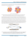
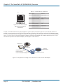
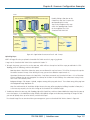
SmartPath Enterprise Wireless System User Guide
Provides the speed, range, security, adapability,
BLACK
BOX at
and manageability to replace wired
networks
an enterprise level.
®
Intelligent 802.1n wireless access points work together
to increase network efficiency.
Customer
Support
Information
Order toll-free in the U.S.: Call 877-877-BBOX (outside U.S. call 724-746-5500)
FREE technical support 24 hours a day, 7 days a week: Call 724-746-5500 or fax 724-746-0746
Mailing address: Black Box Corporation, 1000 Park Drive, Lawrence, PA 15055-1018
Web site: www.blackbox.com • E-mail: info@blackbox.com
Trademarks Used in this Manual
Trademarks Used in this Manual
Black Box and the Double Diamond logo are registered trademarks of BB Technologies, Inc.
Kensington is a registered trademark of Acco Brands Corporation.
AirMagnet is a registered trademark of AirMagnet, Inc.
Apple, iPad, iPhone, Mac, and Macintosh are registered trademarks of Apple Computer, Inc.
Bluetooth is a registered trademark of Bluetooth Sig, Inc.
Cicso and Catalyst are registered trademarks of Cisco Technologies, Inc.
Ekahau is a registered trademark of Ekahau Oy AKA Ekahau, Inc.
ERICO and CADDY are registered trademarks of Erico International Corporation.
Android is a trademark of Google, Inc.
HP and OpenView are registered trademarks of Hewlett-Packard Company.
Tera Term Pro, Hilgraeve, and Hyperterminal are registered trademarks of Hilgraeve, Inc.
Juniper Networks is a registered trademark of Juniper Networks, Inc.
Linux is a registered trademark of Linus Torvalds.
Microsoft, Internet Explorer, Excel, Windows, and Windows Vista are registered trademarks of Microsoft Corporation.
Mozilla and Firefox are registered trademarks of Mozilla Foundation.
UL is a registered trademark of Underwriters Laboratories, Inc.
The Wi-Fi CERTIFIED Logo is a certification mark of the Wi-Fi Alliance.
Any other trademarks mentioned in this manual are acknowledged to be the property of the trademark owners.
We‘re here to help! If you have any questions about your application
or our products, contact Black Box Tech Support at 724-746-5500
or go to blackbox.com and click on “Talk to Black Box.”
You’ll be live with one of our technical experts in less than 30 seconds.
Page 2
724-746-5500 | blackbox.com
FCC and IC RFI Statements
Federal Communications Commission and Industry Canada Radio Frequency Interference
Statements
This equipment generates, uses, and can radiate radio-frequency energy, and if not installed and used properly, that is, in strict
accordance with the manufacturer’s instructions, may cause interference to radio communication. It has been tested and found
to comply with the limits for a Class A computing device in accordance with the specifications in Subpart B of Part 15 of FCC
rules, which are designed to provide reasonable protection against such interference when the equipment is operated in a
commercial environment. Operation of this equipment in a residential area is likely to cause interference, in which case the user
at his own expense will be required to take whatever measures may be necessary to correct the interference.
Changes or modifications not expressly approved by the party responsible for compliance could void the user’s authority to
operate the equipment.
This digital apparatus does not exceed the Class A limits for radio noise emission from digital apparatus set out in the Radio
Interference Regulation of Industry Canada.
Le présent appareil numérique n’émet pas de bruits radioélectriques dépassant les limites applicables aux appareils numériques
de la classe A prescrites dans le Règlement sur le brouillage radioélectrique publié par Industrie Canada.
724-746-5500 | blackbox.com
Page 3
NOM Statement/Radiation Exposure Statement
Instrucciones de Seguridad
(Normas Oficiales Mexicanas Electrical Safety Statement)
1. Todas las instrucciones de seguridad y operación deberán ser leídas antes de que el aparato eléctrico sea operado.
2. Las instrucciones de seguridad y operación deberán ser guardadas para referencia futura.
3. Todas las advertencias en el aparato eléctrico y en sus instrucciones de operación deben ser respetadas.
4. Todas las instrucciones de operación y uso deben ser seguidas.
5. El aparato eléctrico no deberá ser usado cerca del agua—por ejemplo, cerca de la tina de baño, lavabo, sótano mojado o cerca
de una alberca, etc.
6. El aparato eléctrico debe ser usado únicamente con carritos o pedestales que sean recomendados por el fabricante.
7. El aparato eléctrico debe ser montado a la pared o al techo sólo como sea recomendado por el fabricante.
8. Servicio—El usuario no debe intentar dar servicio al equipo eléctrico más allá a lo descrito en las instrucciones de operación.
Todo otro servicio deberá ser referido a personal de servicio calificado.
9. El aparato eléctrico debe ser situado de tal manera que su posición no interfiera su uso. La colocación del aparato eléctrico
sobre una cama, sofá, alfombra o superficie similar puede bloquea la ventilación, no se debe colocar en libreros o gabinetes
que impidan el flujo de aire por los orificios de ventilación.
10. El equipo eléctrico deber ser situado fuera del alcance de fuentes de calor como radiadores, registros de calor, estufas u otros
aparatos (incluyendo amplificadores) que producen calor.
11. El aparato eléctrico deberá ser connectado a una fuente de poder sólo del tipo descrito en el instructivo de operación, o como
se indique en el aparato.
12. Precaución debe ser tomada de tal manera que la tierra fisica y la polarización del equipo no sea eliminada.
13. Los cables de la fuente de poder deben ser guiados de tal manera que no sean pisados ni pellizcados por objetos colocados
sobre o contra ellos, poniendo particular atención a los contactos y receptáculos donde salen del aparato.
14. El equipo eléctrico debe ser limpiado únicamente de acuerdo a las recomendaciones del fabricante.
15. En caso de existir, una antena externa deberá ser localizada lejos de las lineas de energia.
16. El cable de corriente deberá ser desconectado del cuando el equipo no sea usado por un largo periodo de tiempo.
17. Cuidado debe ser tomado de tal manera que objectos liquidos no sean derramados sobre la cubierta u orificios de ventilación.
18. Servicio por personal calificado deberá ser provisto cuando:
A: El cable de poder o el contacto ha sido dañado; u
B: Objectos han caído o líquido ha sido derramado dentro del aparato; o
C: El aparato ha sido expuesto a la lluvia; o
D: El aparato parece no operar normalmente o muestra un cambio en su desempeño; o
E: El aparato ha sido tirado o su cubierta ha sido dañada.
Important: Radiation Exposure Statement
This equipment complies with radiation exposure limits set forth for an uncontrolled environment. This equipment should be
installed and operated with a minimum distance of 8 inches (20 cm) between the radiator and your body. This transmitter must
not be colocated or operating with any other antenna or transmitter. For more information about RF exposure limits, visit
www.fcc.gov (U.S.) or www.ic.gc.ca (Canada).
Page 4
724-746-5500 | blackbox.com
Wi-Fi Certification/EC Conformance/European Community
Wi-Fi Certification
The Wi-Fi CERTIFIED™ Logo is a certification mark of the Wi-Fi Alliance®. The SmartPath APs have been certified for WPA™,
WPA2™, WMM® (Wi-Fi Multimedia™), WMM Power Save, IEEE 802.11d, IEEE 802.11h, and the following types of EAP (Extensible
Authentication Protocol):
• EAP-TLS
• EAP-SIM
• EAP-TTLS/MSCHAPv2
• EAP-AKA
• PEAPv0/EAP-MSCHAPv2
• EAP-FAST
• PEAPv1/EAP-GTC
The SmarPath APs (LWN602A and LWN602HA) have also been certified for short guard interval and 40-MHz operation in the
5-GHz band.
EC Conformance Declaration
Marking by the above symbol indicates compliance with the Essential Requirements of the R&TTE Directive of the European Union
(1999/5/EC). This equipment meets the following conformance standards:
• EN 60950-1 (IEC 60950-1) - Product Safety
• EN 301 893 - Technical requirements for 5-GHz radio equipment
• EN 300 328 - Technical requirements for 2.4-GHz radio equipment
• EN 301 489-1 / EN 301 489-17 - EMC requirements for radio equipment
WEEE and RoHS Compliance
SmartPath products have been reviewed, analyzed, and found to be in compliance with the European Union (EU) directive for
Waste Electrical and Electronic Equipment (WEEE) and with the EU directive for the Restriction of Hazardous Substances (RoHS).
Countries of Operation and Conditions of Use in the European Community
SmartPath APs are intended to be operated in all countries of the European Community. Requirements for indoor vs. outdoor
operation, license requirements and allowed channels of operation apply in some countries as described below.
• Before operating a SmartPath AP, the admin or installer must properly enter the current country code as described in Black Box
product documentation.
NOTE: For U.S. model owners: To comply with U.S. FCC regulations, the country selection function has been completely removed
from all U.S. models. The above function is for non-U.S. models only.
724-746-5500 | blackbox.com
Page 5
Countries of Operation and Conditions of Use in the European Community
• SmartPath APs automatically limit the allowable channels determined by the current country of operation. Incorrectly entering
the country of operation might result in illegal operation and cause harmful interference to other systems. The admin is
obligated to ensure SmartPath APs are operating according to the channel limitations, indoor/outdoor restrictions and license
requirements for each European Community country as described in this section.
• SmartPath APs can be operated indoors or outdoors in all countries of the European Community using the 2.4 GHz band:
Channels 1–13, except where noted below:
– In Italy and Luxembourg, you must apply for a license from the national spectrum authority to operate a SmartPath AP outside
your own premises and for public use or service.
– In Belgium outdoor operation is only permitted using the 2.46- to 2.4835-GHz band: Channel 13.
– In France outdoor operation is limited to the 2.454- to 2.4835-GHz band (Channels 8 to 13) at a maximum of 10 mW EIRP
(effective isotropic radiated power).
– In Norway, the 2.4-GHz band cannot be used outdoors within a 20-km radius of the center of Ny-Ålesund.
– In Russia, the 2.4-GHz band is for indoor use only.
• Because radar systems use some bands in the 5-GHz spectrum, WLAN devices operating in these bands must use Dynamic
Frequency Selection (DFS) to detect radar activity and switch channels automatically to avoid interfering with radar operations.
For the ETSI region, the SmartPath AP (LWN602HA) is certified for the latest ETSI EN 301 893 v1.5.1 DFS requirements and can
use DFS channels 52 to 140 (5.26 GHz to 5.32 GHz, and 5.5 GHz to 5.7 GHz). To comply with ETSI regulations when deploying
a SmartPath AP (LWN602HA) device outdoors, set the 5-GHz radio to operate on the DFS channels and enable DFS. When
deploying a SmartPath AP (LWN602HA) indoors, then the 5-GHz radio can also use Channels 36 to 48 as well as the DFS channels. The maximum transmit power for channels from 36 to 48 is 17 dBm in the ETSI region. Because this maximum is enforced
by SmartPath OS, the SmartPath AP automatically limits the power to 17 dBm even if the setting is greater than that.
• The availability of some specific channels and/or operational frequency bands are country dependent and are firmware
programmed at installation to match the intended destination. The firmware setting is accessible by the end user. Some national
restrictions are noted below:
– In Italy and Luxembourg, you must apply for a license from the national spectrum authority to operate a SmartPath AP outside
your own premises and for public use or service in the 5.15- to 5.35-GHz band (Channels 36 to 64) and 5.47- to 5.725-GHz
band (Channels 100 to 140).
– In Russia, you can only use the 5.15- to 5.35-GHz band at 100 mW (20 dBm) indoors, in closed industrial and warehouse areas,
and on-board aircraft for local network and crew communications during all stages of a flight and for public WLAN access only
at an altitude of 3000 meters or higher. You can only use the 5.65- to 5.825-GHz band with 100 mW EIRP on board aircraft at
an altitude of 3000 meters or higher.
Declaration of Conformity in Languages of the European Community
English: Hereby, we declare that this Radio LAN device is in compliance with the essential requirements and other relevant
provisions of Directive 1999/5/EC.
Finnish: Valmistaja Black Box vakuuttaa täten että Radio LAN device tyyppinen laite on direktiivin 1999/5/EY oleellisten
vaatimusten ja sitä koskevien direktiivin muiden ehtojen mukainen.
Dutch: Hierbij verklaart Black Box dat het toestel Radio LAN device in overeenstemming is met de essentiële eisen en de andere
relevante bepalingen van richtlijn 1999/5/EG. Bij deze Black Box dat deze Radio LAN device voldoet aan de essentiële
eisen en aan de overige relevante bepalingen van Richtlijn 1999/5/EC.
French: Par la présente Black Box déclare que cet appareil Radio LAN est conforme aux exigences essentielles et aux autres
dispositions relatives à la directive 1999/5/CE.
Swedish: Härmed intygar Black Box att denna Radio LAN device står I överensstämmelse med de väsentliga egenskapskrav och
övriga relevanta bestämmelser som framgår av direktiv 1999/5/EG.
Page 6
724-746-5500 | blackbox.com
SmartPath AP Safety Compliance
Danish: Undertegnede Black Box erklærer herved, at følgende udstyr Radio LAN device overholder de væsentlige krav og øvrige
relevante krav i direktiv 1999/5/EF.
German: Hiermit erklärt Black Box, dass sich dieser/diese/ dieses Radio LAN device in Übereinstimmung mit den grundlegenden
Anforderungen und den anderen relevanten Vorschriften der Richtlinie 1999/5/EG befindet". (BMWi) Hiermit erklärt
Black Box die Übereinstimmung des Gerätes Radio LAN device mit den grundlegenden Anforderungen und den
anderen relevanten Festlegungen der Richtlinie 1999/5/EG. (Wien)
Italian: Con la presente Black Box dichiara che questo Radio LAN device è conforme ai requisiti essenziali ed alle altre disposizioni
pertinenti stabilite dalla direttiva 1999/5/CE.
Spanish: Por medio de la presente Black Box declara que el Radio LAN device cumple con los requisitos esenciales y cualesquiera
otras disposiciones aplicables o exigibles de la Directiva 1999/5/CE.
Portuguese: Black Box declara que este Radio LAN device está conforme com os requisitos essenciais e outras disposições da
Directiva 1999/5/CE.
SmartPath AP Safety Compliance
Power Cord Safety
Please read the following safety information carefully before installing a SmartPath AP:
WARNING: Installation and removal of SmartPath APs must be carried out by qualified personnel only.
• SmartPath APs must be connected to a grounded (earthed) outlet to comply with international safety standards.
• Do not connect SmartPath APs to an AC outlet (power supply) without a ground (earth) connection.
• The appliance coupler (the connector to the unit and not the wall plug) must have a configuration for mating with an EN
60320/IEC320 appliance inlet.
• The socket outlet must be near the SmartPath AP and easily accessible. You can only remove power from a SmartPath AP
by disconnecting the power cord from the outlet.
• SmartPath APs operate under Safety Extra-Low Voltage (SELV) conditions according to IEC 60950. The conditions are only
maintained if the equipment to which they are connected also operates under SELV conditions.
• A SmartPath AP receiving power through its Power over Ethernet (PoE) interface must be in the same building as the equipment
from which it receives power.
France and Peru only:
SmartPath APs cannot be powered from IT* supplies. If your supplies are of IT type, then a SmartPath AP must be powered by
230 V (2P+T) via an isolation transformer ratio 1:1, with the secondary connection point labelled Neutral, connected directly to
ground (earth). *Impédance à la terre
IMPORTANT: Before making connections, make sure you have the correct cord set. Check it (read the label on the
cable) against the description in this section.
U.S.A. and Canada only:
• The cord set must be UL® and CSA certified.
• Minimum specifications for the flexible cord:
- No. 18 AWG, not longer than 2 m, or 16 AWG
- Type SV or SJ
- The cord set must have a rated current capacity of at least 10 A.
724-746-5500 | blackbox.com
Page 7
SmartPath AP Safety Compliance
• The attachment plug must be an earth-grounding type with NEMA 5-15P (15 A, 125 V) or NEMA 6-15 (15 A, 250 V)
configuration.
Denmark only:
• The supply plug must comply with Section 107-2-D1, Standard DK2-1a or DK2-5a.
• Switzerland:
• The supply plug must comply with SEV/ASE 1011.
U.K. only:
• The supply plug must comply with BS1363 (3-pin 13 A) and be fitted with a 5-A fuse that complies with BS1362.
• The power (mains) cord must be <HAR> or <BASEC> marked and be of type HO3VVF3GO.75 (minimum).
• IEC-320 receptacle.
Page 8
724-746-5500 | blackbox.com
Table of Contents
Table of Contents
1. Specifications..............................................................................................................................................................................12
1.1 SmartPath AP (LWN602HA)................................................................................................................................................12
1.2 SmartPath AP (LWN602A)...................................................................................................................................................12
1.3 SmartPath EMS VMA (LWN600VMA)..................................................................................................................................13
2.
Preparing for a WLAN Deployment..............................................................................................................................................14
2.1 Assessing Your Requirements..............................................................................................................................................14
2.2 Planning..............................................................................................................................................................................14
2.2.1 Upgrading from Existing Wi-Fi...............................................................................................................................14
2.2.2 New WLAN Deployment........................................................................................................................................15
2.2.3 Site Surveys............................................................................................................................................................15
2.2.4 Budgetiing Wi-Fi: The Chicken and Egg Problem....................................................................................................16
2.2.5 Bandwidth Assumptions for Wi-Fi..........................................................................................................................18
2.2.6 Overcoming Physical Impediments.........................................................................................................................18
2.2.7 Preparing the Wired Network for Wireless.............................................................................................................20
2.2.8 Online Planner.......................................................................................................................................................21
2.3 Operational Considerations.................................................................................................................................................23
2.3.1 Tuning....................................................................................................................................................................23
2.3.2 Spectrum Analysis..................................................................................................................................................23
2.3.3 Troubleshooting.....................................................................................................................................................28
2.3.4 Management.........................................................................................................................................................28
2.3.5 Automatic and Semi-Automatic Rogue Mitigation..................................................................................................28
2.3.6 Deploying with Confidence....................................................................................................................................30
2.4 Basic Wi-Fi Concepts...........................................................................................................................................................30
2.5 New and Enhanced SmartPath OS Features for Release 4.0r1...................................................................................................... 34
2.6 New and Enhanced SmartPath EMS VMA Features for Release 4.0r1.......................................................................................... 34
3.
The Smart Path AP (LWN602HA) Overview..................................................................................................................................36
3.1 Hardware Description..........................................................................................................................................................36
3.2 Ethernet and Console Ports.................................................................................................................................................38
3.2.1 Smart PoE..............................................................................................................................................................39
3.2.2 Aggregate and Redundant Interfaces.................................................................................................................... 40
3.2.3 Console Port..........................................................................................................................................................41
3.3 Status LEDs..........................................................................................................................................................................43
3.4 Antennas............................................................................................................................................................................ 44
3.4.1 Multiple In, Multiple Out (MIMO)...........................................................................................................................45
3.4.2 Using MIMO with Legacy Clients............................................................................................................................47
3.5 Mounting the Smart Path AP (LWN602HA).........................................................................................................................47
3.5.1 Ceiling Mount........................................................................................................................................................47
3.5.2 Plenum Mount.......................................................................................................................................................50
3.5.3 Suspended Mount..................................................................................................................................................52
3.5.4 Surface Mount.......................................................................................................................................................55
3.6 Device, Power, and Environmental Specifications.................................................................................................................56
4.
The Smart Path AP (LWN602A) Overview.....................................................................................................................................57
4.1 Hardware Description.............................................................................................................................................................57
4.2 Ethernet Port.......................................................................................................................................................................58
4.3 Status Indicator...................................................................................................................................................................58
4.4 Antennas.............................................................................................................................................................................59
4.5 Mounting a Smart Path AP (LWN602A) Device....................................................................................................................60
4.5.1 Ceiling Mount........................................................................................................................................................60
4.5.2 Surface Mount.......................................................................................................................................................61
4.6 Device, Power, and Environmental Specifications.................................................................................................................62
724-746-5500 | blackbox.com
Page 9
Table of Contents
5.
The Smart Path EMS VMA (LWN602VMA) ..................................................................................................................................63
5.1 Server Requirements...........................................................................................................................................................63
6.
SmartPath EMS Online................................................................................................................................................................ 64
7.
Using Smart Path EMS..................................................................................................................................................................66
7.1 Installling and Connecting to the Smart Path EMS VMA GUI...............................................................................................66
7.2 Introduction to the Smart Path EMS VMA GUI....................................................................................................................71
7.2.1 Viewing Reports.....................................................................................................................................................72
7.2.2 CAPWAP Latency Reports......................................................................................................................................73
7.2.3 Searching...............................................................................................................................................................74
7.2.4 Multiselecting........................................................................................................................................................74
7.2.5 Cloning Configurations..........................................................................................................................................76
7.2.6 Sorting Displayed Data...........................................................................................................................................77
7.3 Smart Path Configuration Workflow (Enterprise Mode).......................................................................................................78
7.4 Updating Software on Smart Path EMS...............................................................................................................................79
7.5 Updating SmartPathOS Firmware....................................................................................................................................... 80
7.6 Updating SmartPath APs in a Mesh Environment.................................................................................................................81
8.
Basic Configuration Examples.......................................................................................................................................................83
8.1 Example 1: Defining an SSID................................................................................................................................................83
8.2 Example 2: Creating a Cluster..............................................................................................................................................86
8.3 Example 3: Creating a WLAN Policy....................................................................................................................................86
8.4 Access and Backhaul on the Same Radio............................................................................................................................ 88
8.5 Example 4: Connecting Smart Path APs to SmartPath EMS VMA........................................................................................ 90
8.6 Example 5: Assigning the Configuration to SmartPath APs..................................................................................................96
9.
Common Configuration Examples..............................................................................................................................................101
9.1 Example 1: Mapping Locations and Installing SmartPath APs.............................................................................................101
9.1.1 Setting Up Topology Maps...................................................................................................................................102
9.1.2 Preparing the SmartPath APs................................................................................................................................105
9.1.3 NetConfig UI........................................................................................................................................................107
9.2 Example 2: IEEE 802.1x with an External RADIUS Server....................................................................................................109
9.3 Example 3: Providing Guest Access through a Captive Web Portal..................................................................................... 115
9.3.1 Registration Types................................................................................................................................................ 115
9.3.2 Providing Network Settings.................................................................................................................................. 116
9.3.3 Modifying Captive Web Portal Pages...................................................................................................................120
9.3.4 Configuring a Captive Web Portal........................................................................................................................122
9.3.5 IP Firewall Policy Support of Domain Names.........................................................................................................129
9.3.6 VMware PCoIP and Citrix ICA..............................................................................................................................129
9.4 Example 4: Private PSKs....................................................................................................................................................130
9.4.1 Private PSK Enhancements................................................................................................................................... 131
9.4.2 User Profiles.........................................................................................................................................................137
9.4.3 User Profile Reassignment....................................................................................................................................138
9.4.4 Private PDK User Groups......................................................................................................................................140
9.4.5 Importing Private PSK Users................................................................................................................................. 141
9.4.6 Private PSK SSID...................................................................................................................................................142
9.4.7 WLAN Policy........................................................................................................................................................142
9.4.8 E-mail Notification............................................................................................................................................... 143
9.5 Using Smart Path AP Classifiers.........................................................................................................................................143
9.5.1 Set SmartPath AP Classifiers.................................................................................................................................144
9.5.2 Create a VLAN Object with Three Definitions.......................................................................................................145
9.5.3 Reference the VLAN Object..................................................................................................................................145
9.5.4 Update SmartPath APs.........................................................................................................................................145
10.
SmartPath Operating System (OS)..............................................................................................................................................147
10.1 Common Default Settings and Commands........................................................................................................................147
10.2 Configuration Overview....................................................................................................................................................149
Page 10
724-746-5500 | blackbox.com
Table of Contents
10.2.1 Device-Level Configurations.................................................................................................................................149
10.2.2 Policy-Level Configurations..................................................................................................................................149
10.3 SmartPathOS Configuration File Types...............................................................................................................................150
11. Deployment Examples (CLI)........................................................................................................................................................155
11.1 Example 1: Deploying a Single SmartPath AP.....................................................................................................................156
11.2 Example 2: Deploying a Cluster.........................................................................................................................................159
11.3 Example 3: Using IEEE 802.1x Authentication....................................................................................................................164
11.4 Active Directory Configuration Improvement.....................................................................................................................167
11.5 RADIUS Authentication for VHM Administrators...............................................................................................................170
11.6 Example 4: Applying QoS.................................................................................................................................................. 171
11.7 Example 5: Loading a Bootstrap Configuration..................................................................................................................178
11.8 Command Line Interface (CLI) Commands for Examples....................................................................................................180
11.8.1 Commands for Example 1....................................................................................................................................180
11.8.2 Commands for Example 2....................................................................................................................................180
11.8.3 Commands for Example 3....................................................................................................................................181
11.8.4 Commands for Example 4....................................................................................................................................181
11.8.5 Commands for Example 5....................................................................................................................................183
12. Traffic Types ............................................................................................................................................................................185
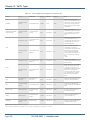
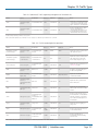
Appendix. Country Codes..................................................................................................................................................................188
724-746-5500 | blackbox.com
Page 11
Chapter 1: Specifications
1. Specifications
1.1 Smart Path AP (LWN602HA)
Antennas: (3) omnidirectional 802.11b/g/n antennas, and (3) omnidirectional 802.11a/n antennas
NOTE: Antennas are not included.
Interface: Serial Port: 9600 bps, 8 data bits, no parity, 1 stop bit, no flow control;
Ethernet: Autosensing 10/100/1000 BASE-T/TX Mbps; both ports comply with the IEEE 802.3af and the 802.at standard
for Power over Ethernet (PoE)
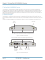
Connectors: (3) RJ-45: (2) 10/100/1000BASE-T/TX Ethernet ports, (1) RJ-45 serial console port; (3) 802.11a/b/g/n RP-SMA ,
(3) 802.11a/n RP-SMA, (1) barrel connector for power
Indicators: (5) Status LEDs: (1) Power, (1) ETH0, (1) ETH1, (1) WIFI0, (1) WIFI1
Temperature Tolerance: Operating: -4 to +131° F (-20 to +55° C);
Storage: -40 to +176° F (-40 to +80° C)
Relative Humidity: 95% maximum
Power: Optional AC power adapter: Input: 100–240 VAC; Output: 48 VDC, 0.625 amps;
*PoE nominal input voltages: 802.3af: 48 VDC, 0.35 amps;
802.3at: 48 V, 0.625 amps;
RJ-45 power input pins: Wires 4, 5, 7, 8 or 1, 2, 3, 6
*NOTE: When using 802.af, power should be applied to both Ethernet ports to maintain all features (see Section 3.2.1, Smart
PoE).
Size: 1.25"H x 8.5"W x 8"D (3.2 x 21.5 x 20.3 cm)
Weight: 3 lb. (1.4 kg)
1.2 Smart Path AP (LWN602A)
Antennas: (2) omnidirectional 802.11b/g/n antennas, and (2) omnidirectional 802.11a/n antennas
Interface: RJ-45 power input pins: Wires 4, 5, 7, 8 or 1, 2, 3, 6
Connectors: (1) RJ-45 autosensing 10/100/1000BASE-T/TX Mbps port; complies with the IEEE 802.3af and the 802.at standard
for Power over Ethernet (PoE), (1) barrel connector for power
Indicators: (1) Status LED that conveys operational states for system power, firmware updates, Ethernet and wireless interface
activity and major alarms
Temperature Tolerance: Operating: +32 to +104° F (0 to +40° C);
Storage: -40 to +185° F (-40 to +85° C)
Relative Humidity: 95% maximum. noncondensing
Power: Optional AC power adapter: Input: 100–240 VAC; Output: 48 VDC, 0.625 amps;
PoE nominal input voltages: 802.3af: 48 VDC, 0.35 amps;
802.3at: 48 V, 0.625 amps;
RJ-45 power input pins: Wires 4, 5, 7, 8 or 1, 2, 3, 6
Size: 2"H x 6.5"W x 6.5"D (5.1 x 16.5 x 16.5 cm)
Weight: 1.75 lb. (0.8 kg)
Page 12
724-746-5500 | blackbox.com
Chapter 1: Specifications
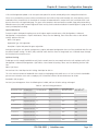
1.3 Smart Path EMS Virtual Management Appliance (VMA) Software (LWN600VMA)
Maximum Supported APs — 1500
Minimum System Requirements — Processor: Dual-core 2 GHz;
Memory: 2 GB VM, 1 GB host;
Storage: 10 GB available disk space
Tested Virtualization Platforms —ESXi 4.0 or better;
Player on CentOS;
Player on Windows Vista®
724-746-5500 | blackbox.com
Page 13
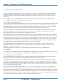
Chapter 2: Preparing for a WAN Deployment
2. Preparing for a WAN Deployment
To ensure a smooth WLAN deployment, you need to begin with a bit of planning. A straightforward review of your deployment
plan before you begin will provide the best results in the least amount of time. The goals of this chapter are to assist you in
assessing your readiness for WLAN implementation and to provide tips and tricks to resolve any issues that might arise in your
environment.
NOTE: This guide assumes an understanding of corporate data networking and past experience with LAN configuration and
deployment. It also assumes some basic Wi-Fi understanding.
2.1 Assessing Your Requirements
To get started with your Black Box WLAN installation, examine the basic requirements of your implementation. First, consider who
your stakeholders are and take the time to fully understand their access requirements. Talk to department managers within your
organization and make sure everyone has documented the full complement of potential network users. Check if the applications
are standard employee applications or if there are other requirements, such as access for guests or consultants.
Next, make a complete list of the application types that your network will need to support. Begin your list with mission-critical
applications, paying special attention to those that generate high levels of traffic and those requiring deterministic behavior.
Identify applications with heavy data requirements and expected service levels.
Demanding applications such as voice and video will require a higher density of access points. Many enterprises are investigating
the potential of VoWLAN (Voice over WLAN) in the hopes of integrating mobile phones and IP-PBX systems. Doing so requires an
evaluation of other data transmission types that can disrupt the quality of voice conversations. Because voice traffic is sensitive to
network jitter and latency, an inadequate number of access points can degrade quality. To the user, excessive jitter and delay can
cause clipped conversations or dropped calls. Additional quality and reliability issues might arise when transmitting video, such as
for training video or surveillance operations, because of the sheer size of the data stream.
Other applications such as network backup and file transfers can also have an impact on the network. Therefore, take into
account any bandwidth-intensive applications if you expect your mobile workforce to be accessing the WLAN while these
applications or services are occurring.
Considering the above issues will result in a more informed—and therefore more successful—deployment plan.
2.2 Planning
This section reviews the fundamental elements for planning your WLAN deployment. This includes conducting a site survey, both
for an upgrade from an existing WLAN and for a completely fresh—or greenfield—deployment.
2.2.1 Upgrading from Existing Wi-Fi
If you are upgrading to SmartPath from an existing WLAN, you already have plenty of data about how your current network is
performing. This information can lead to more informed decisions about your new implementation.
To begin, perform a quick site survey with the existing access points in place. If they are less than three years old and support
802.11g, their coverage and capacity will be lower than the SmartPath 802.11n radio. If the coverage is good and has the appropriate density for your deployment, the simplest approach is to replace one set of access points with a new set of SmartPath APs.
However, this scenario is rare because network upgrades are usually done to improve capacity and to augment the existing layout
with a denser deployment of access points.
Be sure to take note whether your existing network uses “fat” or “thin” APs (access points). A “fat” AP is an autonomous or
standalone access point, which contains the capability to connect to any Ethernet switch. With a “thin” AP, most of the intelligence has been removed and replaced in a centralized WAN controller. An upgrade from fat APs to SmartPath APs is very natural.
Generally, with fat APs you simply need to unplug the existing ones and plug in the new SmartPath APs and provision them. With
this approach, you can maintain or enhance all existing VLANs and security policies. This is a huge advantage over migrating from
fat AP to controller-based solutions because you typically need to re-architect the network.
Page 14
724-746-5500 | blackbox.com
Chapter 2: Preparing for a WAN Deployment
Upgrading from a thin AP solution is also easy. However, because a thin AP makes use of an overlay tunneled network, you
sometimes have to add a local VLAN for access or use tunnels to replicate the overlay network. However, because using VLANs
rather than tunnels provides significant performance and scalability advantages, this is clearly the recommended path.
2.2.2 New WLAN Deployment
In a new—or greenfield—WLAN deployment, you do not have the benefit of an existing network for testing and analysis, which
makes your job a bit more difficult. In this case, the following key questions are critical to the proper design of your WLAN:
• How many users will need wireless service and what applications will they use?
etermining the scope of your WLAN deployment will have a major impact on capacity and coverage. Will only certain groups
D
within the organization have WLAN access, or will it be rolled out across the enterprise? Will you provide guest access to visitors, consultants, and contractors? Most WLANs support just data applications, but many organizations are considering adding
voice services. Voice support raises other design considerations that drive the need for denser deployments of access points and
different Quality of Service (QoS) settings.
• Are there any known major sources of interference?
F or example, is there a nearby cafeteria with microwave ovens? Commercial-grade microwaves are a particularly bad source of
interference. Is there a wireless telephone or video surveillance system not using Wi-Fi? Is there a radar installation nearby? If
you cannot find the answer to these questions easily, consider employing a spectrum analysis product, such as the AirMagnet®
Spectrum Analyzer.
• Are building blueprints available?
ith blueprints, you can see the location of elevators, load-bearing walls, and other building characteristics that can impact
W
signal quality. Different materials, such as concrete walls, brick walls, cubicle walls, glass, and elevator shafts impact signal
quality differently. You can often load these blueprints into a planning or site survey tool to make the process easier.
• What devices need to access the WLAN?
etermine and document the full complement of devices that people will use to access the WLAN. The performance
D
requirements of the WLAN will depend on both the applications and the capabilities of the client devices. For example, design
engineers, architects, and doctors tend to work with bandwidth-hungry applications, so you might need to provide greater
capacity. Conversely, if it is a warehouse with a low client density of mostly barcode scanners, a lower access point density
might be suitable. Finally it is important to consider voice, or the future use of voice. If some or all people will use VoWLAN
(Voice over WLAN) devices, that can affect how many users each access point can accommodate.
NOTE: For some access point User Guidelines, see Section 2.2.5, Bandwidth Assumptions for Wi-Fi.
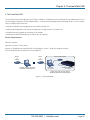
2.2.3 Site Surveys
One of the first questions IT managers ask when they are preparing for a WLAN deployment is whether or not a site survey
should be performed. In a site survey, the administrator walks around the facility with a site survey tool to measure the radio
frequency (RF) coverage of a test access point or the existing WLAN infrastructure.
Whether or not you decide to do a site survey for your enterprise depends on the cost of the survey and the complexity of the
environment. Here are the three ways to deploy a wireless network—with and without a site survey:
• Predeployment Survey
T he safest approach is to perform a site survey before deployment to determine the best locations for the access points.
Typically, site survey professionals temporarily place access points in different locations, take measurements, and adjust their
settings and locations as necessary. After they complete the survey, they install the access points and then perform another site
survey to confirm that the goals have been achieved. This method is clearly the most reliable way to deploy a wireless network;
however, it can be expensive, time consuming, and impractical if an enterprise has many sites.
724-746-5500 | blackbox.com
Page 15
Chapter 2: Preparing for a WAN Deployment
• Deploy and Check
In this scenario, an initial site survey is not performed. Instead, wireless administrators make educated guesses on the best
locations for the access points, or they use a planning tool to determine the locations more reliably. After deploying the access
points, the administrators do a quick site survey. If they need to provide greater coverage, they deploy additional access points.
If there are areas where access points are interfering with each other, they then relocate one or more of them. With cooperative
RF control, SmartPath APs automatically adjust their channel and power to compensate for coverage gaps and areas of
interference.
T he deploy-and-check approach is often much cheaper and faster than doing a predeployment site survey. The risk is that you
might have to move some access points and CAT5 (Category 5) Ethernet cables if you do not plan properly. SmartPath provides
a huge competitive advantage in the deploy-and-check approach, thanks to its flexible mesh networking capability. An
administrator can deploy with mesh (before running wires) and check the performance in several layouts, determine the best
layout, and then run the wires to their final location.
• Deploy without Survey
lthough it is usually advisable to do a site survey, there are many situations in which it is not feasible or even necessary. If the
A
location is sufficiently small—for example, a deployment of only three or fewer access points—site surveys have limited value
because there is virtually no opportunity for interference. If there are numerous remote locations, a site survey might be
impractical because of the cost of traveling to each site. In these locations, you can use a slightly denser deployment to ensure
appropriate coverage and capacity. SmartPath APs automatically adjust their radio power levels to ensure that there is minimal
overlap from interfering channels. Usually the cost of extra access points is offset by the cost saved by not doing a site survey in
a remote location.
2.2.4 Budgeting Wi-Fi: The Chicken and Egg Problem
The hardware cost of a Wi-Fi solution is generally driven by the number of access points needed, and a SmartPath network is no
exception. Unfortunately, a traditional challenge of budgeting for Wi-Fi is that it is difficult to know how many access points to
plan for until you have deployed and measured them. There are methods of doing site surveys before a deployment to answer
these questions. While doing so is often worthwhile, you might just need a general idea of what you should budget. Fortunately
there are some simple guidelines that you can use to figure out how many access points you need, including the number of
access points per square foot, the number of clients per access point, and the distance between access points.
• Access Points per Square Foot
T he simplest and most common way of budgeting access points is per square foot. You simply take the square footage of a
building and divide it by some number. The most common metric used today is one access point for every 4000 to 5000 square
feet for standard offices with cubicles. However, if you need to support voice applications, you need a higher concentration of
access points. In this case, the recommended formula is one access point for every 3000 square feet, or even as low as one
access point for every 2000 square feet. In the lightest weight convenience networks, it is possible to use fewer access points,
and densities as low as one access point for every 10,000 to 15,000 square feet can be successful. Keep in mind that such a
deployment often has dead spots and can only support very low client densities.
• Number of Clients for Each Access Point
nother way to determine the number of access points needed is to consider the number of clients you want each access point
A
to support. In a standard office environment, most enterprises plan to support an average of 5 to 15 clients per access point.
Although the specifications of most access points state that they can support up to about 120 clients, a significantly lower
density is recommended to get an acceptable throughput for standard office applications. If you expect to support voice over
Wi-Fi in the enterprise, account for those phones as well. With the addition of voice, the client density substantially increases,
requiring you to plan for an average of 5 to 10 data clients and 5 to 10 voice clients for each access point. Remember that voice
clients consume virtually zero bandwidth when they are not on a call. However, when they are on a call, it is imperative that the
traffic goes through.
Page 16
724-746-5500 | blackbox.com
Chapter 2: Preparing for a WAN Deployment
• Distance Between Access Points
In a standard office environment, it is a good idea to ensure that access points are between 30 and 100 feet from one another.
A distance of 30 feet is needed in high-density environments and those with many walls separating access points. A distance of
100 feet is sufficient in low-density areas with plenty of open space.
These three tips can help determine how many access points to deploy in a given area. In general, the square footage estimate
provides the best budgeting estimate, with client estimations and the distance between access points confirming the square footage calculations.
As with all rules, there are exceptions. If certain locations in the network have a higher density of clients, such as conference
rooms or lecture halls, a higher density of access points is required. Conversely if there are large open areas with few active
clients, fewer access points are sufficient.
Planning Tools
If following general guidelines does not provide enough confidence or if the deployment environment is particularly challenging,
you might consider using software planning tools like AirMagnet Planner or Ekahau® Site Survey (ESS). Black Box also includes a
free planning tool with the SmartPath AP on-line software. Such tools are useful in determining the placement of access points
without performing a site survey.
Associated Access Point Costs
After you determine how many access points you need, it becomes simpler to determine the other costs involved with deploying
Wi-Fi because most are driven by the quantity of access points. These costs include the following:
• Installation and Wiring
- CAT5: CAT5 wiring is required for all SmartPath APs acting as portals.* One advantage of SmartPath networks is that you can
deploy SmartPath APs in a mesh to avoid some of the wiring costs.
- Power: Power lines are required for all SmartPath APs acting as mesh points.† Portals receive power through power lines or
through Ethernet cables by using the Power-over-Ethernet (PoE) option.
- Installation: SmartPath APs can simply snap into standard dropped-ceiling environments. However, if the installation is in a
warehouse or any environment without dropped ceilings, consider the installation costs.
• Infrastructure: PoE Switches
You must cable every SmartPath AP acting as a portal to a switch port. For PoE, there are several considerations:
- 802.3af: The current PoE specification provides enough power for all 802.11a/b/g access points.
- 802.3at: The current PoE specification supports higher power devices like 802.11n access points.
- PoE injectors and midspans: These save money on switch upgrades by injecting power into standard Ethernet connections.
• Site Survey and Debugging Software
- F or a sizable deployment, you probably will use site survey and debugging software. Deployment and troubleshooting tools
from Ekahau and AirMagnet pay for themselves very quickly. These products enable the validation of a deployment and allow
you to troubleshoot client and access point issues. (For more information, see Section 2.3, Operational Considerations.)
• Professional Services
- When deploying wireless LANs, professional services are often required to perform site surveys.
*A portal is a cluster member that links one or more mesh points to the wired LAN.
†Mesh points are cluster members that use a wireless backhaul connection to link through a portal to the wired LAN.
724-746-5500 | blackbox.com
Page 17
Chapter 2: Preparing for a WAN Deployment
• Client Software
- Depending on the deployment, users can use built-in Microsoft® Windows®, Linux® and/or Macintosh® client software
(supplicants).
- For better services and troubleshooting, consider a third-party supplicant such as Juniper Networks® Odyssey Client.
2.2.5 Bandwidth Assumptions for Wi-Fi
People frequently talk about how much coverage an access point provides; however, it is capacity—not coverage—that typically
constrains an access point in an enterprise environment. The challenge is not how far the RF signal can travel (coverage), but how
to deliver enough bandwidth to meet the demands of business applications (capacity). In other words, you might be able to cover
an office of 50 people with one access point, but if all 50 people choose to access it at the same time, it might become overloaded. Indeed, if you use the formulas provided in this paper, you should find the saturation of access points on your campus to be
more than sufficient. Enterprise users are accustomed to speedy switched networks and expect similar performance from their
wireless LAN connections. This is why documenting the size and type of applications that will rely on your WLAN is so critical to
your planning. In short, if you plan for optimal capacity, complete coverage will follow automatically.
In general, the way to increase capacity is to add more access poisnts (within reason) and tune down the radio power to avoid
interference. One reason for deploying a high-capacity network is to create a WLAN for voice and data applications. In such a
WLAN, everyone has a VoIP handset running wirelessly all the time.
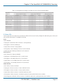
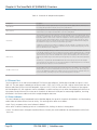
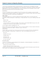
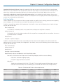
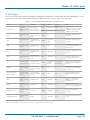
In general, the following table shows the standard densities for office deployments:
Table 2-1. Standard densities for office deployments.
Expected Data Rate
with 802.11n Clients
Office Requirements
Expected Data Rate
with 802.11g Clients
20 MHz
40 MHz
Access Point Density)
Coverage (low capacity)
12 to 24 Mbps
-39 Mbps
-81 Mbps
1 access point per 8000 square feet
Standard office deployment
36 Mbps
-104 Mbps
-216 Mbps
1 access point per 5000 square feet
Standard office deployment with voice
54 Mbps
-130 to -144 Mbps
-270 to -300 Mbps
1 access point per 2000 to 3000 square feet
NOTE: Data rate is not the same as TCP throughput. Because of various headers, inter-frame gaps, and session creation, real TCP
throughput usually does not exceed 22 Mbps at data rates of 54 Mbps.
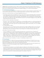
2.2.6 Overcoming Physical Impediments
Not every potential deployment is a standard business campus. The following scenarios are a few that merit special consideration.
• Open Space
O
pen spaces, such as a large foyer or an outdoor area, are very easy to cover with Wi-Fi because there are few impediments to
propagation and fewer opportunities for multipath interference. In such spaces, Wi-Fi signals can propagate many hundreds of
feet. This is good if you want to provide coverage for just a few users.
ou will run into challenges if there are many users and high-capacity service goals. In these situations, it is important to tune
Y
down the RF to a minimal level. The SmartPath APs do this on their own automatically. Another trick is to take advantage of
obstacles that block Wi-Fi. Look for trees or walls and put neighboring access points on either side of them. Doing so limits the
interference of the two access points and allows for the installation of more access points with less interference.
• Warehouse and Retail
arehouse and retail environments present many challenges. One of the largest challenges is that RF characteristics often
W
change because of varying inventory levels and, in the case of retail, seasonal displays (such as tinsel or a stack of soda cans on
an end cap). Additionally, metal shelves and high ceilings can be challenges to propagation. To resolve with these issues, it is
wise to put at least one access point per aisle to ensure coverage for that aisle. This usually requires a higher density of access
points than would otherwise be required.
Page 18
724-746-5500 | blackbox.com
Chapter 2: Preparing for a WAN Deployment
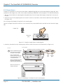
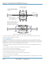
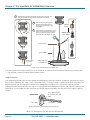
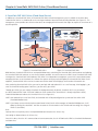
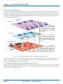
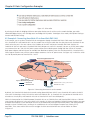
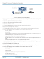
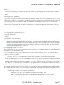
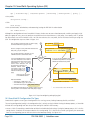
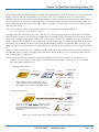
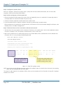
• Configuring Antennas
s anyone who has administered a WLAN system in the past knows, proper configuration of the access point antennas
A
at the outset can save you lots of trouble. The SmartPath AP (LWN602A) has internal antennas that cannot be adjusted.
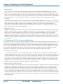
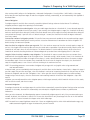
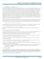
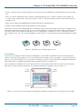
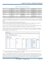
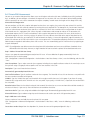
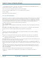
However, the antennas for the SmartPath (LWN602HA) are adjustable. The SmartPath AP (LWN602A) has a pair of fixed, dualband omnidirectional antennas; and the SmartPath AP (LWN602HA) can support up to six single-band omnidirectional antennas
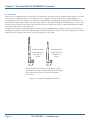
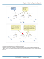
(three for the 2.4-GHz radio and three for the 5-GHz radio). You typically orient these antennas vertically, positioning the antennas on all SmartPath APs in the same direction. Omnidirectional antennas create a coverage areas that can be toroidal (doughnut-shaped) or cardioid (heart- or plum-shaped), broadcasting to the sides much more effectively than up or down (see Figure
2-1). In general, this is good for most office environments because you have large flat floors. However, it can be a problem in
environments with high ceilings.
Toroidal Pattern Cardioid Pattern
Figure 2-1. Omnidirectional antenna radiation patterns.
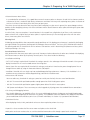
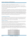
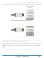
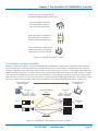
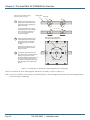
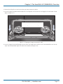
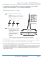
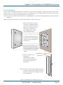
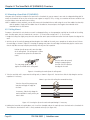
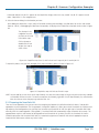
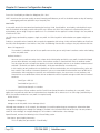
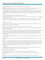
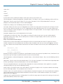
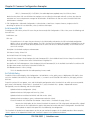
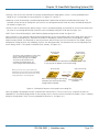
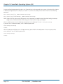
The SmartPath AP can accommodate external antennas via coaxial jacks on its chassis. The jack is a standard male RP-SMA connector. Various patch, directional, and omnidirectional antennas can be used to change the coverage pattern. The most common
external antennas are patch antennas. These are directional antennas that provide coverage in a single direction. Most commonly
they have a transmission pattern as shown in Figure 2-2. Based on the gain, the signal will be wide (like the low gain antenna
shown on top) or narrow and long (like the high gain antenna shown on the bottom). Note that the coverage patterns are not
perfect for these antennas and that they often broadcast slightly in other directions than the primary one. These extra “lobes”
can be seen in both of the patterns shown below.
Bird’s Eye
Eye View)
View
(Bird’s
Patch
Patch Antennas
Antennas
Lower Gain
Gain
Lower
Higher Gain
Higher
Figure 2-2. Directional antenna patterns.
724-746-5500 | blackbox.com
Page 19
Chapter 2: Preparing for a WAN Deployment
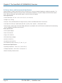
The following are some quick hints for deploying access points:
• Standard sheetrock walls and dropped ceilings are the best locations for mounting access points.
• When deploying WLANs in retail stores, doing a site survey at each store is likely to be impractical. It is more common to run
detailed site surveys at a few locations and use the results to set up User Guidelines for the remaining sites.
• Be aware of metal-lined firewalls, steel pillars, and other metallic surfaces. RF signals can reflect off metal surfaces, which can
cause unexpected coverage patterns. Also watch out for objects that can block or reflect signals, such as mirrors, plants, walls,
steel doors, elevator shafts, and bathroom stalls.
• The quality and performance of a Wi-Fi network is a function of the signal-to-noise ratio. To avoid noise issues, check the area
for common noise generators such as industrial microwave ovens, wireless video cameras, cordless phones and headsets, and
Bluetooth devices. Such devices especially cause interference in the 2.4-GHz spectrum.
• Plan appropriately for high ceilings. With an omnidirectional antenna, the downward coverage is not great. In normal office
space, the ceilings rarely exceed 15 feet, so this issue does not come up very often. In environments such as warehouses, where
ceilings can be up to 50 feet high, ceiling-mounted access points are not optimal. It is best to deploy them on non-metallic walls
about 10 feet to 15 feet above the floor. If this is not feasible, using patch antennas can help direct the RF energy downward.
• In high-density or high-capacity environments, placing access points on exterior walls allows for a greater number of cells inside
the building and more capacity. In other deployments, it is recommended that the outer access points be no farther than
30 feet from the exterior walls to ensure coverage.
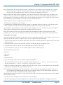
2.2.7 Preparing the Wired Network for Wireless
One of the advantages of moving to a Black Box WLAN is that you do not have to make changes to the underlying network, such
as putting controllers into wiring closets. This can save you considerable time and effort during installation. However, some
network changes might make sense for some deployments. For example, you might want to add additional VLANs or security
settings. This section covers a few of the more common considerations that IT departments are handling.
• 802.1Q VLANs
S martPath APs can segment users into VLANs if an administrator wants. This decision can be made by a returned RADIUS attribute or it can be configured as part of a user profile or SSID. Enterprises often set up separate VLANs for wireless and guest
access, so that this traffic is segmented from the rest of the network; however, it is possible to set up any number of other
VLANs for further segmentation.
• Firewalls
epending on the environment, enterprises might use firewalls to segment wired and wireless data. This can be implemented
D
as a discrete firewall enforcing traffic between VLANs or between ports, or you might use the stateful firewall that is integrated
in SmartPath OS (the SmartPath AP operating system).
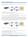
• RADIUS Authentication
If RADIUS authentication is required, then a RADIUS server must be in place and be able to support the necessary protocols for
wireless—often called 802.1X EAP types: PEAP, EAP-TLS, EAP-TTLS, WEP 8021.x (dynamic WEP), LEAP, EAP-FAST, and captive
web portal authentication using CHAP.
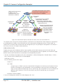
• DNS and DHCP Configuration
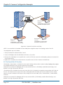
If you use the SmartPath EMS VMA (see Section 2.3, Operational Considerations), it is possible to install SmartPath APs without
any extra configuration and they will be able to contact SmartPath EMS VMA for management. If the SmartPath APs are linked
to a different subnet than the one to which SmartPath EMS VMA is connected, then you can set either a DHCP option or DNS
entry to give the location of SmartPath EMS VMA (see “How SmartPath APs Connect to SmartPath EMS VMA” in Section 8.4,
Example 4: Connecting SmartPath Units).
Page 20
724-746-5500 | blackbox.com
Chapter 2: Preparing for a WAN Deployment
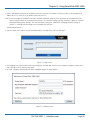
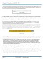
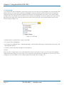
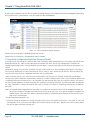
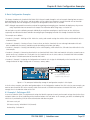
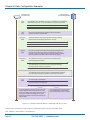
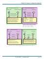
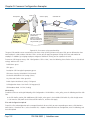
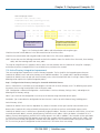
2.2.8 Online Planner Enhancements
Several enhancements were made to improve the usability and accuracy of the on-line planner.
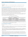
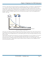
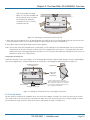
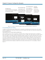
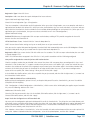
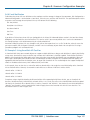
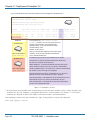
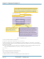
Perimeter Wall Type: You can now specify a wall type for building perimeter walls. The perimeter is the blue line that defines the
area of a building in which SmartPath EMS VMA can automatically place SmartPath AP icons. To apply a wall type to a perimeter
that you have already drawn, right-click the perimeter line, click “Change Wall Type," and then choose Dry Wall (3 dB), Brick Wall
(10 dB), or Concrete (12 dB). (See Figure 2-3.) To apply a wall type in previous releases, you had to draw a blue perimeter, and
then trace over it with another wall type, such as a brick wall. The new approach is much more efficient.
Figure 2-3. Choosing wall type.
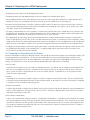
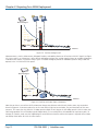
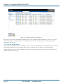
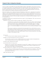
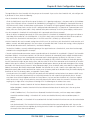
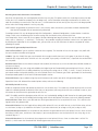
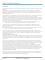
Wall Opacity: The main purpose of adding walls to a map is to show their effect on signal attenuation. After adding walls—
including perimeter walls—you can diminish their opacity so that they blend into the background map instead of standing out
prominently in the foreground. To adjust their opacity, click Operation > Global Settings, or right-click the top-level map name,
and click “Global Settings.” Then choose the percent of opacity that you want for the walls from the Opacity of walls drop-down
list (see Figure 2-4).
Figure 2-4. Wall opacity.
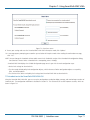
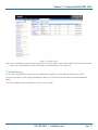
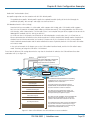
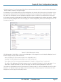
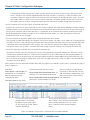
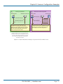
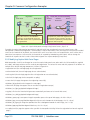
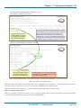
Meaningful SmartPath AP Host Names: When using the Auto Placement feature, SmartPath EMS VMA automatically names the
SmartPath AP icons. However, names like “LWN602A-0021400” are not particularly meaningful. You can give them names like
"Lobby" or "Conf Room 1," which makes it easier for installers to use an exported PDF report to know where each one goes. To
change the host name of a SmartPath AP icon, right-click it, and then edit the Host Name field in the AP Details dialog box that
appears (see Figure 2-5). To see the host names in the GUI and in PDF reports, choose “Host Name” from the AP Labels dropdown list on the View tab.
724-746-5500 | blackbox.com
Page 21
Chapter 2: Preparing for a WAN Deployment
Figure 2-5. AP details.
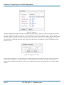
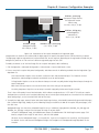
Setting the Navigation Tree Width: By default, the width of the navigation tree is 180 pixels. If you want to make the tree wider
or narrower, based on the length of map names and the depth of the nested structure, you can reset the width by clicking
Operation > Update Tree Width (see Figure 2-6). Then enter a different value in pixels and click “Update.” Different administrators
can define different settings, which SmartPath EMS VMA retains for each one when they return to the topology section. Note
that making the tree width too narrow can cause some of the information in the notifications section at the bottom of the tree
panel to be cut off.
Figure 2-6. Navigation tree width.
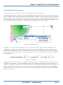
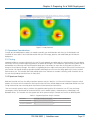
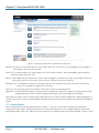
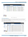
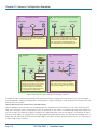
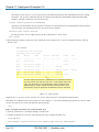
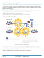
Auto Placement Improvements: The calculation for the automatic placement of SmartPath AP icons on a map has been revised
to leave smaller coverage holes on maps (see Figure 2-7). The automatic placement of icons, especially on smaller floor plans,
sometimes left considerable coverage holes. With the new improvements, coverage is now greater than 90% and often greater
than 95%.
Page 22
724-746-5500 | blackbox.com
Chapter 2: Preparing for a WAN Deployment
Figure 2-7. Auto placement.
2.3 Operational Considerations
To make your WLAN deployment process as smooth as possible, you should consider more than just the distribution and
installation of access points. You should also consider how you will manage, optimize, and troubleshoot your WLAN after
deployment.
2.3.1 Tuning
Approach building an enterprise WLAN with the same life-cycle approach you would apply to a wired network. After you deploy
the WLAN, revisit key network engineering processes to account for changes in the environment. Watch for access points that are
overloaded or are underused, and check for potential dead spots. Furthermore, be aware that the likely points of failure can
change as the environment changes. For example, a neighboring business might install access points that cause RF interference on
your network. You should schedule and perform periodic walkthroughs to ensure that the design goals of the wireless network
continue to be met. The SmartPath EMS VMA provides quick views into how the network is behaving, which SmartPath APs are
the most heavily loaded, and which have the most clients.
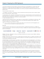
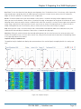
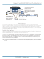
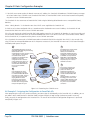
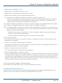
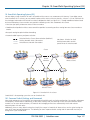
2.3.2 Spectrum Analysis
Black Box SmartPath APs have the ability to perform spectrum analysis in both the 2.4-GHz and 5-GHz band. Spectrum analysis
provides a live view of the RF environment so that you can plan for further WLAN deployment or troubleshoot WLAN issues such
as high retransmission rates caused by device interference or slow connections from overuse.
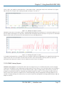
There are two main spectrum analysis functions: the graphical rendering of the RF environment in an FFT trace and swept
spectrogram, and the identification of interference devices such as cordless phones, microwave ovens, video bridges, and
Bluetooth devices. The SmartPath APs that support each of the spectrum analysis functions are listed in the following table:
Table 2-2. Supported spectrum analysis functions.
Access Point
FFT Graphs and Swept Spectrographs
Interference Device Identification
SmartPath AP (LWN602A)
Yes
Yes
SmartPath AP (LWN602HA)
No
No
724-746-5500 | blackbox.com
Page 23
Chapter 2: Preparing for a WAN Deployment
The number of SmartPath APs that can perform a spectral scan concurrently varies depending on the SmartPath EMS VMA
platform you use. SmartPath EMS VMA Virtual Appliance limits the number of concurrent scans to two (that is, only two
SmartPath APs can perform spectrum analysis functions as the same time); the physical SmartPath EMS VMA permits up to 20
concurrent scans.
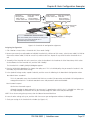
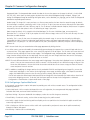
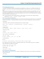
To start the spectrum analyzer feature:
1. Click Monitor > Access Points > SmartPath APs, select the SmartPath AP on which you want to start the spectrum analyzer
feature, and then click Tools > Spectrum Analysis.
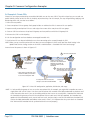
A message appears with a warning that performing spectrum analysis on the selected SmartPath AP will affect performance and
prompts you to confirm your decision. As a general rule, try to use this tool on SmartPath AP portals that are not actively serving
clients rather than on mesh points with which clients are currently associated.
2. If you want to continue, click “Yes.”
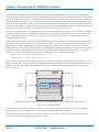
SmartPath EMS VMA immediately initiates the analysis tool on the selected SmartPath AP and displays the analysis pane, which
contains three main areas: a status bar at the top of the pane, an area containing the graphical analysis feedback, and an
interference reporting area at the bottom of the pane.
NOTE: To use the spectrum analysis feature on a radio in access mode, you must have at least one SSID configured on your
WLAN on at least one SmartPath AP running SmartPath OS 4.0r1.
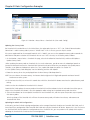
Status Bar
The status bar contains a brief overview of the current analysis parameters, including which SmartPath AP is employed, the
frequency band and channels, and the time remaining in the analysis. In addition to the parametric information, four navigation
buttons are also displayed.
Figure 2-8. Status bar.
Settings: Click to open a dialog box in which you can change the parameters of the spectrum analysis. Modify the following
settings, and then click “Update:”
Interface: Choose which interface you want to use to collect data by the band with which it is associated. If you choose 2.4 GHz
(11n/b/g), then the SmartPath AP uses its wifi0 interface to monitor the 2.4-GHz band. If you choose 5 GHz (11n/a), then it uses
its wifi1 interface to monitor the 5-GHz band.
2.4-GHz Channels: This field only appears if you choose 2.4 GHz (11n/b/g) from the Interface drop-down list. In this field, you
can enter any combination of channels that occurs in the 2.4-GHz band. If you are entering noncontiguous channels, then separate the channel numbers by commas. If you are entering a range of channels, use the hyphen ( - ) to indicate the range. For
example, to monitor Channel 1, 5, and the range 7 through 11, then enter 1, 5, 7-11 into this field. To monitor the entire band,
enter 1-11, or 1-13, or 1-14, depending on the channels allowed for your region.
5.0-GHz Channels: This field only appears if you choose 5 GHz (11n/a) from the Interface drop-down list. In this field you can
enter any combination of channels that occurs in the 5-GHz band. If you are entering noncontiguous channels, then separate the
channel numbers by commas. If you are entering a range of channels, use a hyphen ( - ) to indicate the range. For example, to
monitor Channel 36, 48, and the range 149 through 165, then enter 36, 48, 149-165 into this field. To monitor the entire band,
enter 36-165.
Data Collect Interval: The data collection interval refers to the time interval between scans of the spectrum. Each time the
SmartPath AP scans the spectrum, it updates the display. If the data collection interval is five seconds, then the SmartPath AP
scans every five seconds and updates the display. You can change the interval from 1 to 30 seconds. The default is a one-second
interval.
Page 24
724-746-5500 | blackbox.com
Chapter 2: Preparing for a WAN Deployment
Run Time: The run time determines how long the scanning process lasts. The default run time is five minutes, which is generally
long enough to get a rough idea of the RF (radio frequency) environment. For more intense scrutiny of the RF environment,
longer run times are called for. The maximum run time is eight hours.
Return: The Return button returns you to the Monitor > Access Points > SmartPath APs page without stopping the analysis.
When you return to the Monitor > Access Points > SmartPath APs page, an icon appears to the right of the SmartPath AP name
indicating that the spectrum analysis feature is enabled, which means that an analysis is running. To return again to the spectrum
analysis page, simply click this icon or perform the same steps to start an analysis. Attempting to start an analysis while one is
already running does not start a new instance; rather, it returns to the view of the current analysis in progress.
Stop: When you click “Stop,” the current analysis ends. SmartPath EMS VMA appliance allows for 10 concurrent scans, and
SmartPath EMS Online displays the Monitor > Access Points > SmartPath APs page again.
Maximize: Clicking the maximize button (four outward-pointing arrows) on the status bar causes the entire pane to be maximized to fill the browser frame. To return to the normal view, simply click the Restore Down button (four inward-pointing arrows)
in the upper right corner of the browser.
Graphical Analysis Feedback Area
The graphical analysis feedback area displays four representations of the received signals, arranged by default in a two-by-two
array.
Figure 2-9. Graphical analysis.
724-746-5500 | blackbox.com
Page 25
Chapter 2: Preparing for a WAN Deployment
Each of the representations can be enlarged to fill the entire analysis pane to provide more detail or to increase its visibility, or be
deleted from the array to simplify the display. To change the display in this manner, use the buttons in the upper right corner of
each of the representations.
Pause/Resume: You can suspend a trace by clicking the Pause button. When you click “Pause,” the button becomes a Resume
button (right-pointing triangle). To resume the trace, click “Resume.”
NOTE: Pausing one of the displays does not affect any of the other displays and does not stop the collection of data. When you
resume a display, it returns to displaying data as if there were no interruption.
Maximize: Click the Maximize button (four outward-pointing arrows). This causes the small display to enlarge to fill the entire
content pane of the page. This is distinct from the Maximize button on the status bar, which maximizes the content pane to fill
the browser. To return to the smaller view, click the Restore Down button. This causes the display to return to the previous
arrangement.
Close: When you click the Close [ x ] button, the affected display disappears and the neighboring display expands to fill the
vacated area. To recover a closed display, navigate away from the spectrum analysis page and then return to it. When you return,
SmartPath EMS VMA again organizes the display in its default arrangement.
A description of each of the four graphical representations of the RF environment follows:
Real-time FFT: The real-time FFT is a trace that indicates the power of a signal (vertical axis) along a domain of frequencies
(horizontal axis). The term FFT (fast Fourier transform) refers to the mathematical algorithm used to decompose received signals
into their component’s frequencies. Within this display, there are two traces: the red trace indicates the real-time power levels,
whereas the gray trace indicates the maximum power level reached during the current data collection session.
On maximizing this display, you gain access to the following additional display parameters:
Band: You can choose which band you want to monitor in this display: 2.400-2.500 GHz, 5.150-5.350 GHz, 5.470-5.725 GHz, or
5.725-5.850 GHz.
Channels: Choose one of the channel combinations in the drop-down list to display channel boundaries within the graph.
Center: Use this control to scroll the graph right or left. You can use the Center control in combination with the Span control to
zoom in on a specific area of the frequency domain.
Span: This control establishes the width of the viewable area, effectively zooming in on the center frequency. Use this control
with the Center control to zoom in on a specific area of the frequency domain.
Reference Level: By default, the reference level of the graph (the top line) is 0 dBm. When used with the Vertical Scale control,
you can zoom in on a specific portion of the actual trace.
By changing the reference level using this control, you can also view very low power levels near the noise floor. In a very quiet
environment, the noise floor is generally between -130 dBm and -90 dBm; in very noisy or busy environments, it is much higher.
Vertical Scale: The vertical scale of a graph indicates how much vertical distance on the graph corresponds to power. By default,
the vertical scale is set to 10 dB, which means that a power change of 10 dB corresponds to a specific, physical vertical distance
on the graphic display. Changing that setting to 5 dB doubles the vertical resolution of the graph. Because there are many
different sizes of monitors, the actual scale that you see in your browser is relative.
Max Hold: By default, this check box is selected and SmartPath EMS VMA displays the gray trace that indicates the maximum
power level reached during the current data collection session. To turn off the gray trace, clear the check box.
FFT Duty Cycle: The FFT duty cycle is the amount of time as a percent of total time that the SmartPath AP receives a signal
above 20 dB above the noise floor. FFT duty cycle is often referred to as channel utilization because it indicates to what extent a
channel is actually in use in terms of the relative amount of time the signal is present (vertical axis). Within this display, there are
two traces: the red trace indicates the real-time duty cycle, whereas the gray trace indicates the maximum duty cycle reached
during this data collection session.
Page 26
724-746-5500 | blackbox.com
Chapter 2: Preparing for a WAN Deployment
On maximizing this display, you gain access to the following additional display parameters:
Band: You can choose which band you want to monitor in this display: 2.400-2.500 GHz, 5.150-5.350 GHz, 5.470-5.725 GHZ, or
5.725-5.850 GHz.
Channels: Choose one of the channel combinations in the drop-down list to display channel boundaries within the graph.
Center: Use this control to scroll the graph right or left. You can use this control in combination with the Span control to zoom in
on a specific area of the frequency domain.
Span: This control establishes the width of the viewable area, effectively zooming in on the center frequency. Use this control
with the Center control to zoom in on a specific area of the frequency domain.
Maximum: By default, the maximum is set to 100%. This means that when the trace reaches the top of the graph, it has a duty
cycle of 100%. You can use this control to set a lower maximum to gain resolution. When used with the Minimum control, you
can zoom in on a specific portion of the trace.
Minimum: By default, the minimum is set to 0%. This means that when the trace reaches the bottom of the graph, it has a duty
cycle of 0%. You can use this control to set a higher minimum to gain resolution. When used with the Maximum control, you can
zoom in on a specific portion of the trace.
Max Hold: By default, this check box is selected and SmartPath EMS VMA allows for 10 concurrent scans, and SmartPath EMS
Online displays the gray trace that indicates the maximum duty cycle reached during this data collection session. To turn off the
gray trace, clear the checkbox.
Swept Spectrogram: A swept spectrogram tracks the signal power over time. That is, it produces a color-coded sweep of
spectral information such that the admin can view the real-time FFT in terms of its historical values. The swept spectrogram—also
called a heat map—reports the frequency on the horizontal axis, the history (in sweeps) on the vertical axis, and the power
encoded as a set of colors. Blue indicates low power levels, whereas red indicates high power levels; the gradient of colors from
light blue, through green, yellow, and orange, indicates intermediate power levels.
On maximizing this display, you gain access to the following additional display parameters:
Band: You can choose which band you want to monitor in this display: 2.400-2.500 GHz, 5.150-5.350 GHz, 5.470-5.725 GHz, or
5.725-5.850 GHz.
Channels: Choose one of the channel combinations in the drop-down list to display channel boundaries within the graph.
Swept Spectrogram-FFT Duty Cycle: A swept spectrogram of the FFT duty cycle tracks the duty cycle over time. This spectrogram produces a color-coded sweep of duty cycle information with frequency on the horizontal axis, history (in sweeps) on the
vertical axis, and the duty cycle encoded as a set of colors. Blue colors indicate low duty cycle (the darkest blue is 0%), whereas
red colors indicate high duty cycles (the darkest red is 100%); the gradient of colors from light blue, through green, yellow, and
orange, indicates intermediate duty cycle values.
On maximizing this display, you gain access to the following additional display parameters:
Band: You can choose which band you want to monitor in this display: 2.400-2.500 GHz, 5.150-5.350 GHz, 5.470-5.725 GHz, or
5.725-5.850 GHz.
Channels: Choose one of the channel combinations in the drop-down list to display channel boundaries within the graph.
Both swept spectrograms together provide a useful view of how the RF environment behaves over time, which in turn provides
clues to uncovering problems, such as identifying intermittent interference sources.
Interference Reporting Area
The interference reporting area at the bottom of the pane displays any sources of RF interference that the spectrum analyzer can
identify. This area provides a summary of all interference sources for quick review. This area contains six columns to help identify
the affected channels and the approximate position of the interference.
724-746-5500 | blackbox.com
Page 27
Chapter 2: Preparing for a WAN Deployment
AP Name: The name of the SmartPath AP that is reporting the interference. If an interference source is reported by a few
SmartPath APs, but not others, you can use this to approximate the physical location of the interference.
Device Type: SmartPath EMS VMA maps the signature of the interference to a specific device type such as a cordless phone,
microwave oven, or Bluetooth, which it then reports in the Device Type column. The device type listing can help determine
whether the interference source might be a security concern.
Discovered: This column shows the date and time that the SmartPath AP discovered the source of the interference. You can track
regular, periodic, and intermittent interference sources using this information.
Channel Affected: When SmartPath EMS VMA identifies an interference source, the channel in which it occurs appears here.
Center Frequency: The center frequency of the affected channel appears in this column.
Occupied Bandwidth: This column displays the bandwidth of the affected range of frequencies.
NOTE: The last three columns contain redundant information and provide the same information from different perspectives so
that you can gain a more a complete understanding of the affected frequencies and channels.
Table 2-3. Interference reporting.
AP Name
Device Type
Discovered
Channel Affected
Center Frequency
Occupied Bandwidth
SmartPathAP-0e5580
Microwave oven
2011-05-17 12:09:17
9
2542
20
SmartPathAP-0e5580
Microwave oven
2011-05-17 12:04:22
10
2457
20
During the brief intervals of time that the spectrum analyzer is sampling, no data transfer occurs. However, if the SmartPath AP is
very busy processing wireless traffic (that is, it has a high duty cycle), then the sampling and analysis can subtly impact the performance. In addition, any analysis that monitors multiple channels must accommodate the added time needed for the scanning
interface to switch channels.
2.3.3 Troubleshooting
Some of the most common issues that arise after deploying a new wireless network are RF interference, RADIUS issues, and desktop client issues. The first step in troubleshooting is to look at logs and use debug commands. Black Box offers an extensive set of
event monitoring and debug tools that you can use through SmartPath EMS VMA, the SmartPath AP network management system. For additional troubleshooting, particularly of clients or neighboring networks, Black Box recommends two tools, which are
available on the Internet: Ethereal Warehouser (http://www.wireshark.org/) and AirMagnet Laptop Analyzer (http://www.airmagnet.com/products/laptop.htm).
2.3.4 Management
Current Wi-Fi networks typically span an entire company and have complex security policies. Fortunately, the SmartPath EMS
VMA Network Management System makes it simple to manage large networks from a central location. It provides a single centralized management instance for the entire wireless network. Although managed SmartPath APs can operate without SmartPath
EMS VMA, it simplifies the provisioning of global policy management and centralized configuration and monitoring. SmartPath
EMS VMA lowers operating costs by speeding deployment, configuration, and monitoring of the wireless network.
Managing faults and alarms is critical to maintaining uptime. You can view and manage events through SmartPath EMS VMA logging. Optionally, you can use a third-party tool such as HP® OpenView®.
SmartPath EMS VMA makes it easy to monitor and troubleshoot SmartPath APs within a WLAN infrastructure. SmartPath EMS
VMA can import hierarchical map views that represent the physical location of the network, from the perspective of the entire
world down to the floor level.
2.3.5 Manual, Automatic, and Semi-Automatic Rogue Mitigation
You can manually mitigate rogue APs and their clients, or you can configure SmartPath APs to mitigate them automatically upon
detection. You can also use a semi-automatic approach in which you determine when to start and stop the mitigation and allow
the SmartPath APs to determine which SmartPath APs carry out the deauth attacks that comprise the mitigation effort.
Page 28
724-746-5500 | blackbox.com
Chapter 2: Preparing for a WAN Deployment
After creating a WIPS policy on the Configuration > Advanced Configuration > Security Policies > WIPS Policies > New page,
define how you want to perform rogue AP and client mitigation: manually, automatically, or semi-automatically. Each approach is
described below.
Manual Mitigation
To mitigate rogue APs and their clients manually, expand the Optional Settings section and select Manual. The following
mitigation parameters apply when operating in manual mode:
Period for client detection and mitigation: After you enable rogue detection on a SmartPath AP, it scans detected rogue APs
for clients during the period of time that you specify. If you manually start mitigation against a rogue, the SmartPath AP not only
continues scanning for clients during this period, it also sends deauth frames to the rogue AP and any detected clients during the
same period. For example, if you leave this at its default setting of 1 second, the SmartPath AP checks for rogues and attacks
them every second.
Consecutive number of mitigation periods: This specifies how many consecutive periods of time to spend attacking a rogue
AP and its clients before allowing client inactivity to cause a ceasefire and commence a countdown to end the mitigation. The
default setting is 60 consecutive periods.
Max time limit for mitigation efforts per rogue AP: This is the maximum amount of time that an attack against a rogue AP
can last. If the length of client inactivity does not cause the attack to be suspended or if you do not manually stop the attack, the
SmartPath AP will stop it when this time limit elapses. The default duration is 14,400 seconds (4 hours), which means that a
SmartPath AP continues checking for clients of a detected rogue for up to four hours and mitigating them if it finds them.
Length of client inactivity needed to stop mitigation: The SmartPath AP stops an attack when there are no more clients
associated with the mitigated rogue AP for this length of time. The default setting is 3600 seconds (1 hour). If the SmartPath AP
detects any associated clients before this length of time elapses, it sends a deauth flood attack and resets the counter to begin
the countdown again. If there are no more clients associated with the AP after this length of time elapses, the SmartPath AP
stops the mitigation process—even if there is still time remaining in the maximum time limit.
NOTE: The remaining parameter—max number of mitigator APs per rogue AP—only applies when using automatic and
semi-automatic modes.
In Manual mode, you must periodically check for rogue APs and their clients on the Monitor > Access Points > Rogue APs page. If
you find a rogue that you want to mitigate, select the checkbox in each row of a reporting SmartPath AP that you want to use to
perform the mitigation, and then click “Mitigation > Start.” When you think that the mitigation process has continued long
enough and you want to stop it, select the check box of each attacking SmartPath AP and then click Mitigation > Stop. With
manual
mitigation, you manually control the entire mitigation process: which rogues to attack, which SmartPath APs to use in the attack,
when to start the attack, and when to stop it.
Automatic Mitigation
To configure SmartPath APs to mitigate rogue APs and their clients automatically, expand the Optional Settings section and select
Automatic. In this mode, SmartPath APs automatically start and stop the mitigation process without any administrator
involvement.
When you select Automatic, the following option appears: Automatically mitigate rogue APs only if they are connected to your
network. By default, this check box is selected. This ensures that SmartPath APs only attack rogue APs that are in their backhaul
network, not APs in external networks that happen to be within radio range.
NOTE: Be careful not to attack legitimate external APs. If there are neighboring wireless LANs within radio detection range, only
enable automatic mitigation of rogue APs detected in your own network.
724-746-5500 | blackbox.com
Page 29
Chapter 2: Preparing for a WAN Deployment
All the parameters in the Mitigation Parameters for Rogue APs and Their Clients section apply to SmartPath APs that perform
automatic mitigation. In addition to the parameters explained above, there is one other:
Max number of mitigator APs per rogue AP: For automatic and semi-automatic mitigation, cluster members choose one
SmartPath AP to be the arbitrator AP, which is the one to which all the detector APs send reports. The arbitrator AP also determines which detector APs perform mitigation. When they start, they become mitigator APs. Set the number of mitigator APs that
the arbitrator AP can automatically assign to attack a rogue AP and its clients.
Semi-Automatic Mitigation
To configure SmartPath APs to mitigate rogue APs and their clients semi-automatically, expand the Optional Settings section and
select Semi-Automatic. This approach combines elements of both the manual and automatic approaches. Like manual mitigation,
you must periodically check for rogue APs and their clients on the Monitor > Access Points > Rogue APs page, choose a rogue AP
to mitigate, and start the mitigation process. Like automatic mitigation, the arbitrator AP automatically chooses which SmartPath
APs perform the attack. Because the arbitrator AP determines which SmartPath APs perform the mitigation, it does not matter
which entries on the Rogue APs page you select or how many you select. The arbitrator AP decides which SmartPath AP to assign
to do mitigation based on two factors: radio channels and RSSI values. If a SmartPath AP is already using the same channel as a
rogue AP, the arbitrator is likely to assign it as a mitigator AP so that it does not have to change channels to launch its attack. If
one SmartPath AP reports a stronger RSSI value for a rogue AP than another SmartPath AP, that also increases the likelihood of it
being selected as a mitigator because it is within closer attack range of the rogue and its clients.
2.3.6 Deploying with Confidence
Moving a large enterprise—or even a small one—to a WLAN for the very first time need not be daunting. If you have moderate
experience with LAN deployments of other types and you have taken time to get answers to the important questions that will
affect the network data load, you have every prerequisite for success. The bottom line is to remember to take stock of your
project before you begin to ward against unforeseen costs and performance bottlenecks. If you have considered the issues and
guidelines presented here, you are not far away from a successful WLAN deployment.
2.4 Basic Wi-Fi Concepts
The goal of this section is to provide some background on Wi-Fi propagation and how to lay out a wireless network. Although
radio frequency (RF) engineering is a rather complicated science, this section provides a simple overview on the basics of Wi-Fi
propagation and channel layout that you need to be able to install an enterprise WLAN.
The first thing to know is that Wi-Fi is forgiving. Wi-Fi tends to transmit a bit farther than you expect, and even in cases of
interference, it tends to just work. This can be both a blessing and a curse. It is a blessing because people will likely have access
to the network, and it is a curse because your overall performance might be suboptimal without obvious symptoms, like lack of
connectivity. Understanding the basics presented in this section will help ensure a high-performance layout.
The first concept to understand is signal strength and how it relates to throughput. Radio power is measured in decibels relative
to one milliwatt (dBm) where 0 dBm = 1 milliwatt, but decibels increase using a log10 math function. Rather than dusting off
your old math books and pulling out your calculator, look at the dBm-to-milliwatt converter that appears below. Often in Wi-Fi,
dBm and milliwatts (mW)—and microwatts (µW)—are used interchangeably. The following table converts between the two units
of measurement:
Table 2-4. dBm-to-milliwatt conversions.
Page 30
dBm-to-milliwatt
dBm-to-milliwatt
20 dBm = 100 mW
2 dBm = 1.6 mW
15 dBm = 32 mW
1 dBm = 1.3 mW
10 dBm = 10 mW
0 dBm = 1.0 mW
5 dBm = 3.2 mW
-1 dBm = 794 µW
4 dBm = 2.5 mW
-5 dBm = 316 µW
3 dBm = 2.0 mW
-10 dBm = 100 µW
724-746-5500 | blackbox.com
Chapter 2: Preparing for a WAN Deployment
In RF, there is also a relative measurement that you can use to compare two numbers. This measurement is simply dB (without the
“m”). To see how this concept is applied, consider how radio signal propagation changes over a distance and how it can be
affected. Figure 2-3 shows signal strength over distance as a curve that has the best signal strength closer to the access point. It
also shows noise. In general, noise is considered to be low-level background RF signals that can interfere with a WLAN. This noise
tends to be the garbled background RF that comes from everything from the sun and stars to man-made interfering devices like
Bluetooth® headsets. It is impossible to block out noise, and it should not be attempted. This low level of background noise is
called the “noise floor.”
Received Signal
Signal-to-Noise
Ratio
Noise
Distance
Figure 2-10. Path loss in an open space.
When clients send a packet, the ratio of the signal-to-noise (SNR) level defines the quality of the link, which is directly related to
the performance of the network. Based on the SNR, the client and AP negotiate a data rate in which to send the packet, so the
higher the SNR the better. For good performance, the SNR should be greater than 20 dB, and for optimal performance it should
be at least 25 dB.
Signal strength not only diminishes over distance, but it can also be affected by objects in the way (see Figure 2-4). This can be a
wall, a tree, or even a person. There is a fairly predictable dB drop through most objects that also decreases the SNR, thus
decreasing the data rate. Although this appears to be a bad thing, clever Wi-Fi installers use it to their advantage. It enables them
to place more access points in a tighter spot by using pre-existing walls and other impediments to Wi-Fi propagation to keep
them from interfering with each other.
724-746-5500 | blackbox.com
Page 31
Chapter 2: Preparing for a WAN Deployment
Received Signal
Wall
Signal-to-Noise
Ratio
Noise
Distance
Figure 2-11. Path loss through a wall.
Microwave ovens, wireless video cameras, Bluetooth headsets, and cordless phones can all interfere with Wi-Fi signals (see Figure
2-5). Excess noise in an environment is often difficult to diagnose and can have a major negative impact on network performance.
To discover noise sources, a spectrum analysis system is needed. AirMagnet provides an affordable spectrum analysis tool that
operates in the 2.4-GHz and 5-GHz spectra.
Received Signal
Signal-to-Noise
Ratio
Noise
Distance
Figure 2-12. Path loss with noise (from a microwave).
Now that you have a sense of how Wi-Fi performance changes over distance and with noise, look at some ways to perform
channel assignment. If two access points are on the same channel right next to each other, they are forced to share the same
spectrum. This means that they share the 54-Mbps speeds available in 802.11a/g or the 300-Mbps speeds in 80211n rather than
each being capable of 54- or 300-Mbps speeds independently. This essentially halves the bandwidth for each access point. To
manage this situation, make sure that neighboring APs are on different channels and that their power is adjusted so that it does
not overlap that of other APs with the same channel.
Page 32
724-746-5500 | blackbox.com
Chapter 2: Preparing for a WAN Deployment
In the 2.4 GHz spectrum, there are 11 channels in the United States. However, a Wi-Fi signal consumes more than one channel.
Consequently, there are only 3 non-overlapping channels: 1, 6, and 11. To achieve optimal performance, you need to design a
channel layout pattern such as the one on the left in Figure 2-6.
7-to-1 Layout Pattern
3-to-1 Layout Pattern
36 52
6
1
6
11
1
36 52 60 64 40
11
1
6
11
6
11
6
1
11
1
11
6
1
6
1
11
1
11
11
6
1
60 64 40 44 56 36 52
6
11
1
6
44 56 36 52 60 64 40
36 52 60 64 40 44 56
60 64 40 44 56 36 52
44 56 36 52 60 64 40
60 64 40 44 56
44 56
Figure 2-13. Channel layout patterns.
NOTE: There are alternative 2.4-GHz channel layouts, such as one for four channels using 1, 4, 8 and 11 and another using
channels 1, 5, 9 to counter interference from microwaves, which tend to cause interference in the high end of the
spectrum. Black Box recommends alternative channel layouts only for the most challenging radio environments.
Designing a channel pattern is easier for the 5-GHz spectrum. Depending on the country and the device being used, there are
between 4 and 24 channels available for Wi-Fi use. However, in most countries there are at least eight 40-MHz-wide channels
with which to work. To simplify the layout of more than 3 channels, most use a 7-to-1 pattern, as is shown on the right in Figure
2-6. This channel layout is much more flexible than the 3-channel system and allows for much better capacity over all channels.
The last topic to cover is the concept of multipath. When a client receives a transmission from an access point (or vice versa), the
RF signal reaches the client first through a “direct path,” but then shortly thereafter by the “indirect paths” reflected off other
objects. The direct path combined with the indirect paths make up multipaths (see Figure 2-7). RF signals can bounce off almost
anything—walls, people, plants, and so on—but they bounce off metal most. As the RF signals bounce about while propagating,
one or more of the secondary paths can interfere with the primary path, causing the signal strength of the direct path to
diminish. In doing so, multipath can greatly decrease signal-to-noise ratio with legacy 802.11a/g radios. With 802.11n, a certain
amount of multipath is desirable and increases performance.
Secondary Path
Primary Path
Secondary Path
Figure 2-14. Multipath radio waves.
NOTE: If you would like to learn more about how radio-frequency propagation works or the details of 802.11, Wikipedia provides
excellent background information under the entries “IEEE 802.11,” “radio propagation,” and “multipath.” Additionally,
spending a few hours with a site survey tool such as AirMagnet Surveyor or the Ekahau Site Survey (ESS) and a few test
APs can increase both your familiarity with Wi-Fi propagation and your confidence about how it behaves.
724-746-5500 | blackbox.com
Page 33
Chapter 2: Preparing for a WAN Deployment
2.5 New and Enhanced SmartPath OS Features for Release 4.0r1
Spectrum Analysis: You can use up to ten SmartPath APs to function as spectrum analyzers for fixed lengths of time. You can
use the spectrum analyzer feature to monitor both the 2.4-GHz and 5-GHz bands. Each SmartPath AP performing spectrum analysis provides a real-time FFT (fast Fourier transform) trace that displays the frequency-power relationship, along with a swept spectrogram to monitor power and frequency changes over time. It also provides an FFT duty cycle trace that indicates how busy the
medium is, along with another swept spectrogram to monitor changes in the duty cycle over time. Additionally, SmartPath APs
can identify many sources of interference by their RF (radio frequency) signatures.
Access and Backhaul on the Same Radio: When operating SmartPath APs as mesh points, you can configure SmartPath AP
radios to operate simultaneously as an access interface and a backhaul interface. This not only provides a failover mechanism if
one of the wireless interfaces fails or loses connectivity, it also allows single radio implementations to service clients and act as
mesh points at the same time.
Automatic and Semi-Automatic Rogue Mitigation: In addition to manually mitigating rogue APs and their clients, you can
configure SmartPath APs to mitigate them automatically upon detection. You can also use a semi-automatic approach in which
you determine when to start the mitigation and allow the SmartPath APs to determine which SmartPath APs carry out the deauth
attacks that comprise the mitigation effort.
Private PSK Enhancements: You can set up a captive Web portal that allows users to self-register and receive their own
individual private PSKs. You can also configure SmartPath APs to generate private PSKs in bulk on a recurring basis with varying
expiration times. Finally, you can configure an SSID so that it automatically binds a private PSK to the MAC address of the first
client that uses it, reserving the key for exclusive use by that client until the private PSK lifetime expires or until an admin manually
unbinds it.
User Profile Reassignment: SmartPath APs can reassign users to different user profiles based on their MAC addresses or OUIs,
operating systems, and device domain names. This allows a user to go on the network with the same credentials, but be assigned
one user profile when using one type of device and a different profile when using another.
NetConfig UI: By default, SmartPath APs act as DHCP clients, so that when you put them on a network, they automatically
obtain appropriate network settings from a DHCP server. However, when a network uses static IP addressing, you must configure
network settings manually on all devices attached to that network. To ease deployment in such circumstances, SmartPath APs
support a NetConfig UI that allows you to ready a SmartPath AP for use on your network quickly and easily. The NetConfig UI is a
Web user interface through which you can manually configure the IP address, netmask, and gateway for a SmartPath AP and
configure SmartPath EMS VMA connectivity settings so that after the SmartPath AP is connected to the network, you can continue configuring and managing it through SmartPath EMS VMA.
IP Firewall Policy Support of Domain Names: IP firewall policies now support domain names as the source and destination in
their rules.
VMware PCoIP and Citrix ICA: With both PCoIP (PC-over-IP) and Citrix ICA (Independent Computing Architecture) desktop
virtualization protocols now predefined as services, you can quickly create firewall rules to allow or block these two services.
2.6 New and Enhanced SmartPath EMS VMA Features for Release 4.0r1
Active Directory Configuration Improvement: The internal processes used to connect to or query an Active Directory domain
are now more streamlined to simplify the initial setup required to integrate a SmartPath AP RADIUS server with an Active
Directory server. Also, you can now use SmartPath EMS VMA in Express mode to configure a SmartPath AP RADIUS server to
work with an Active Directory server—a feature formerly available only when using Enterprise mode.
RADIUS Authentication for VHM Administrators: In previous SmartPath EMS VMA versions, it was only possible to use
RADIUS authentication for home system administrators when no VHMs were present. Now both home system and VHM
administrators can be authenticated through an external RADIUS server.
Page 34
724-746-5500 | blackbox.com
Chapter 2: Preparing for a WAN Deployment
CAPWAP Latency Reports: SmartPath EMS VMA tracks the average latency in its CAPWAP connections to each managed
SmartPath AP and displays an icon indicating the average amount of current latency in the Connection column on the Monitor >
Access Points > SmartPath APs page when viewed in Monitor mode. A green hexagon indicates normal latency, based on an
average that SmartPath EMS VMA has calculated from periodic SmartPath AP reports. The icon changes to yellow when the
latency increases to the point that responsiveness has slowed noticeably; however, configuration and image uploads can still
succeed. It changes to orange when connectivity issues reach the point that configuration and image upload attempts might no
longer be successful.
Online Planner: Several enhancements were made to improve the usability and accuracy of the on-line planner.
724-746-5500 | blackbox.com
Page 35
Chapter 3: The SmartPath AP (LWN602HA) Overview
3. The SmartPath AP (LWN602HA) Overview
The SmartPath AP is a high-performance and highly reliable 802.11n wireless access point. The SmartPath AP provides dual
concurrent 802.11b/g/n and 802.11a/n radios for 3x3 MIMO (Multiple In, Multiple Out) and dual 10/100/1000 Ethernet ports for
link aggregation or link redundancy. Its power management system uses a concept called smart Power over Ethernet (PoE) to
adjust its power consumption automatically in response to the available power in different environments. Smart PoE supports the
IEEE 802.3af and 802.3at standards.
3.1 Hardware Description
The SmartPath AP is a multichannel wireless access point. It is compatible with IEEE 802.11b/g/n (2.4 GHz) and IEEE 802.11a/n
(5 GHz) standards and supports a variety of wireless fidelity (Wi-Fi) security protocols, including Wi-Fi Protected Access (WPA) and
WPA2.
You can see the hardware components on the SmartPath AP in Figures 3-1 and 3-2. Each component is described in Table 3-1.
Device
Lock Slot
Status LEDs
5 GHz (C)
5 GHz (B)
5 GHz (A)
802.11b/g/n RP-SMA Connectors for Detachable Single-Band Antennas
Figure 3-1. SmartPath AP front panel.
802.11a/n RP-SMA Connectors for Detachable Single-Band Antennas
2.4 GHz (A)
ETH0
ETH1
10-/100-/ 1000-Mbps
PoE Ports
48V DC
(.625A)
2.4 GHz (B)
Power Connector
CONSOLE
RESET
Console Reset
Port
Button
Figure 3-2. SmartPath AP back panel.
Page 36
724-746-5500 | blackbox.com
2.4 GHz (C)
Chapter 3: The SmartPath AP (LWN602HA) Overview
Table 3-1. SmartPath (LWN602HA) component descriptions.
Component
Description
Status LEDs
The status LEDs convey operational states for system power, firmware, Ethernet
interfaces, and radios. For details, see Section 3.3, Status LEDs.
Device lock slot
You can physically secure the SmartPath AP by attaching a lock and cable
(such as a Kensington® notebook lock) to the device lock slot or by using the lock
adapter that is included in the mounting kit and a padlock. For more information,
see “Locking the SmartPath AP” in Section 3.5.1, Ceiling Mount.
802.11a/b/g/n RP-SMA connectors
You can connect up to six detachable single-band antennas to the male
802.11a/b/g/n reverse polarity-subminiature version A (RP-SMA) connectors.
Connect the longer antennas, which support 2.4-GHz frequencies (for IEEE
802.11b/g/n), to the connectors on the side panel with the Ethernet ports.
Connect the shorter antennas, which support 5-GHz frequencies (for IEEE
802.11a/n), to the connectors on the side panel with the device lock slot.
For details, see Section 3.4, Antennas.
10-/100-/1000-Mbps ports
The two 10-/100-/1000-Mbps Ethernet ports—ETH0 and ETH1—support IEEE
802.3af and 802.3at PoE and have RJ-45 connectors. The SmartPath AP can
receive power through one or both Ethernet connections from power sourcing
equipment (PSE) that is compatible with the 802.3af standard and the 802.3at
standard, such as one of the PoE injectors available as an optional accessory from
Black Box. (If you connect the SmartPath AP to a power source through the power
connector and PoE ports simultaneously, the device draws power through the
power connector and automatically disables PoE.)
You can configure ETH0 and ETH1 as two individual Ethernet interfaces, combine
them into an aggregate interface to increase throughput, or combine them into a
redundant interface to increase reliability. You can connect the SmartPath AP to a
wired network or to a wired device (such as a security camera) through these
ports using bridging. They are compatible with 10/100/1000BASE-T/TX and automatically negotiate half- and full-duplex connections with the connecting device.
They are autosensing and adjust to straight-through and cross-over Ethernet
cables automatically. For details, see Section 3.2, Ethernet and Console Ports.
Power connector
The 48-volt DC power connector (0.625 amps) is one of two methods through
which you can power the SmartPath AP. To connect it to a 100–240-volt AC
power source, use the AC/DC power adapter that is available as an extra option
(LWN600PS-US, LWN600PS-UK, or LWN600PS-EU). Because the SmartPath AP
does not have an on/off switch, connecting it to a power source automatically
powers on the device.
Console port
You can access the CLI by making a serial connection to the RJ-45 console port.
The management station from which you make a serial connection to the
SmartPath AP must have a VT100 emulation program, such as Tera Term Pro
(a free terminal emulator) or Hilgraeve® Hyperterminal® (provided with Windows®
operating systems). The following are the serial connection settings: bits per second: 9600, data bits: 8, parity: none, stop bits: 1, flow control: none. For details,
see Section 3.2, Ethernet and Console Ports.
Reset button
The reset button allows you to reboot the device or reset the SmartPath AP to its
factory default settings. Insert a paper clip, or something similar, into the Reset
pinhole and press the reset button. To reboot the device, hold the button down
between 1 and 5 seconds. To return the configuration to the factory default settings, hold it down for at least 5 seconds. After releasing the button, the Power
LED goes dark as the system reboots. Then it pulses green while the firmware
loads and the system performs a self-test. After the software finishes loading, the
Power LED glows steady green.
To disable the reset button from resetting the configuration, enter this command:
no reset-button reset-config-enable Pressing the button between 1 and 5 seconds
will still reboot the SmartPath AP, but pressing it for more than 5 seconds will not
reset its configuration.
724-746-5500 | blackbox.com
Page 37
Chapter 3: The SmartPath AP (LWN602HA) Overview
NOTE: The rear surface of the SmartPath AP is used for heat dissipation to reduce the internal temperature. Consequently, it can
become hot, so use caution when handling it.
3.2 Ethernet and Console Ports
There are three ports on the SmartPath AP: two RJ-45 10/100/1000BASE-T/TX Ethernet ports and an RJ-45 console port. The pin
assignments in the PoE (Power over Ethernet) Ethernet ports follow the TIA/EIA-568-B standard (see Figure 3-3 and Table 3-2).
The ports accept standard types of Ethernet cable—CAT3, CAT5, CAT5e, or CAT6—and can receive power over this cable from
power sourcing equipment (PSE) that is 802.3af-compatible. If you use CAT5, CAT5e, or CAT6 cables, the SmartPath AP can also
support 802.3at-compliant PSE. Such equipment can be embedded in a switch or router, or it can come from purpose-built devices that inject power into the Ethernet line en route to the SmartPath AP. Because the PoE ports have autosensing capabilities, the
wiring termination in the Ethernet cable can be either straight-through or cross-over.
8
Table 3-2. PoE wire usage and pin assignments.
1
802.3af Alternative
A (Data and Power
on the Same Wires)
802.3af Alternative B
(Data and Power on
Separate Wires)
802.3at Wiring Options
ETH0
Figure 3-3. View of the ETH0
PoE port on the SmartPath AP
(LWN602HA).
Pin
Data Signal
MDI
MDI-X
MDI or MDI-X
1
2
3
4
1
Transmit +
DC+
DC-
—
DC1+
DC1-
DC1+
DC1-
2
Transmit -
DC+
DC-
—
DC1+
DC1-
DC1+
DC1-
3
Receive +
DC-
DC+
—
DC1-
DC1+
DC1-
DC1+
4
Not used
—
—
DC+
DC2+
DC2+
DC2-
DC2-
5
Not used
—
—
DC+
DC2+
DC2+
DC2-
DC2-
6
Receive -
DC-
DC+
—
DC1-
DC1+
DC1-
DC1+
7
Not used
—
—
DC-
DC2-
DC2-
DC2+
DC2+
8
Not used
—
—
DC-
DC2-
DC2-
DC2+
DC2+
MDI = Medium-dependent interface for straight-through connections.
MDI-X = Medium-dependent interface for crossover connections
The PoE ports are autosensing and can automatically adjust to transmit and receive data over straight-through or crossover
Ethernet connections. Likewise, they can automatically adjust to 802.3af Alternative A and B power delivery methods.
Furthermore, when the Alternative A method is used, the ports automatically allow for polarity reversals depending on their role
as either MDI or MDI-X. In 802.3at, the 1/2 and 3/6 wire pairs connect to DC source 1 and 4/5 and 7/8 pairs to DC source 2 in
PSE. Although the exact polarity depends on the PSE design, the SmartPath AP Ethernet ports can support all possible options.
Page 38
724-746-5500 | blackbox.com
Chapter 3: The SmartPath AP (LWN602HA) Overview
Table 3-3. T568A Wire
Color.
Pin
T568A Wire Color
1
1
8
White/Green
2
Green
3
White/Orange
4
Blue
5
White/Blue
6
Orange
7
White/Brown
8
Brown
Figure 3-4. T568A Terminated Ethernet Cable with an RJ-45 connector.
Table 3-4. T568B Wire
Color.
Pin
1
8
T568A Wire Color
1
White/Orange
2
Orange
3
White/Green
4
Blue
5
White/Blue
6
Green
7
White/Brown
8
Brown
Figure 3-5. T568B Terminated Ethernet Cable with an RJ-45 connector.
T568A and T568B are two standard wiring termination schemes. Note that the only difference between them is that the white/
green + solid green pair of wires and the white/orange + solid orange pair are reversed.
For straight-through Ethernet cables—using either the T568A or T568B standard—the eight wires terminate at the same pins on
each end.
For cross-over Ethernet cables, the wires terminate at one end according to the T568A standard and at the other according to
T568B.
3.2.1 Smart PoE
The SmartPath AP (LWN602HA) applies the concept of smart PoE to adjust power consumption as necessitated by varying levels
of available power. The SmartPath AP supports PoE on both its ETH0 or ETH1 interfaces and can draw power through either one
or through both simultaneously. Based on the available power that the SmartPath AP detects, it manages its internal power use
by making the following adjustments:
724-746-5500 | blackbox.com
Page 39
Chapter 3: The SmartPath AP (LWN602HA) Overview
• No adjustments are needed when the power level is 20 W (watts) or higher. If the available power drops to a range between 18
and 20 W, the SmartPath AP disables its ETH1 interface, assuming that it is drawing power through its ETH0 interface. If it is
drawing power solely through its ETH1 interface, then it disables its ETH0 interface instead.
• If the power level drops to the 15–18 W range, the SmartPath AP then switches from 3x3 MIMO (Multiple In, Multiple Out) to
2x3 (see Section 3.4.1, MIMO).
• In rare cases when the power drops between 13.6 and 15 W and further power conservation is necessary, the SmartPath AP
reduces the speed on its active Ethernet interface—ETH0 or ETH1—from 10/100/1000 Mbps to 10/100 Mbps.
• Finally, if there is a problem with the PoE switch or Ethernet cable, and the power falls between 0 and 13.6 W, the SmartPath
AP disables its wireless interfaces and returns its ETH0 and ETH1 interfaces to 10-/100-/1000-Mbps speeds.
Through the application of smart PoE, the SmartPath AP can make power usage adjustments so that it can continue functioning
even when the available power level drops.
3.2.2 Aggregate and Redundant Interfaces
By default ETH0 and ETH1 act as two individual Ethernet interfaces. When both interfaces are connected to the network and are
in backhaul mode, the SmartPath AP transmits broadcast traffic only through ETH0. The SmartPath AP transmits broadcast traffic
through ETH1 only when ETH0 does not have network connectivity. When both Ethernet interfaces are connected to the network
and are in access mode, then the SmartPath AP transmits broadcast traffic through all the access interfaces: ETH0, ETH1, and all
wireless subinterfaces in access mode.
In addition to using ETH0 and ETH1 as individual interfaces, you can combine them into an aggregate interface (agg0) to increase
throughput, or combine them into a redundant interface (red0) to increase reliability. The logical red0 and agg0 interfaces support
all the settings that you can configure for Ethernet interfaces except those pertaining to physical link characteristics such as link
speed. For configuration information, see the next sections.
Aggregate Interface
You can increase throughput onto the wired network by combining ETH0 and ETH1 into a single logically aggregated interface
called "agg0". The aggregate interface effectively doubles the bandwidth that each physical interface has when used individually.
In this configuration, both Ethernet ports actively forward traffic, the SmartPath AP applying an internal scheduling mechanism
based on the source MAC address of each packet to send traffic through the aggregate member interfaces. To configure an
aggregate interface, enter the following commands:
interface eth0 bind agg0
interface eth1 bind agg0
In addition to configuring the SmartPath AP, you must also configure the connecting switch to support EtherChannel. For example, the following commands bind two physical Ethernet ports—0/1 and 0/2—to the logical interface port-channel group 1 on a
Cisco® Catalyst® 2900 switch running Cisco IOS 12.2:
Switch#conf t
Switch(config)#interface port-channel 1
Switch(config-if)#switchport mode access
Switch(config-if)#spanning-tree portfast
Switch(config-if)#exit
Switch(config)#interface fastEthernet 0/1
Switch(config-if)#switchport mode access
Switch(config-if)#channel-group 1 mode on
Switch(config-if)#spanning-tree portfast
Page 40
724-746-5500 | blackbox.com
Chapter 3: The SmartPath AP (LWN602HA) Overview
Switch(config-if)#exi
Switch(config)#int fastEthernet 0/2
Switch(config-if)#switchport mode access
Switch(config-if)#channel-group 1 mode on
Switch(config-if)#spanning-tree portfast
Switch(config-if)#exit
Switch(config)#exit
Switch#wr mem
Finally, you must cable the Cisco switch and the SmartPath AP together: Cisco 0/1 to SmartPath AP eth0, and Cisco 0/2 to
SmartPath AP eth1.
Redundant Interface
If a single Ethernet link provides sufficient bandwidth and speed, such as a 1000-Mbps link, but you want to ensure link redundancy, you can connect the two Ethernet ports to the same switch—or to two different switches—and configure them to act as
a redundant interface called "red0". In this mode, only one Ethernet interface is actively forwarding traffic at any one time. If eth0
is active and eth1 is passive and eth0 loses its connection, the SmartPath AP switches over to eth1. To configure a redundant
interface, enter the following commands:
interface eth0 bind red0 primary
interface eth1 bind red0
The interface that you specify as primary is the one that the SmartPath AP uses when both interfaces have network connectivity.
Because the SmartPath AP uses eth0 as the primary interface by default, it is unnecessary to specify “primary” in the first
command above. However, it is included to make the role of eth0 as the primary interface obvious.
NOTE: No extra configuration is necessary on the connecting switch or switches to support a redundant interface.
Interface Selection for the Default Route
In cases where there are multiple active interfaces in backhaul mode, the SmartPath AP uses the following logic to choose which
interface to use in its default route:
• If there is an Ethernet interface and a wireless interface in backhaul mode, the SmartPath AP uses the Ethernet interface in its
default route.
• If there are multiple Ethernet interfaces in backhaul mode, the SmartPath AP chooses which one to use in its default route in
the following order:
- It uses red0 or agg0 if one of them has at least one member interface bound to it and its link state is UP.
- It uses ETH0 if neither red0 nor agg0 has any member interfaces and the link state for ETH0 is UP.
- It uses ETH1 if neither red0 nor agg0 has any member interfaces, the link state for ETH0 is DOWN, and the link state for ETH1 is
UP.
3.2.3 Console Port
The pin-to-signal mapping in the RJ-45 console port is shown shown in Figure 3-6.
724-746-5500 | blackbox.com
Page 41
Chapter 3: The SmartPath AP (LWN602HA) Overview
Table 3-5. Console port pin assignments.
8
1
CONSOLE
Figure 3-6. View of the console
port on the SmartPath AP
(LWN602HA).
Pin
Signal
Direction
1
RTS (Request to Send)
Output, unused
2
DTR (Data Terminal Ready)
Output, unused
3
TXD (Transmitted Data)
Output
4
Ground
Ground
5
Ground
Ground
6
RXD (Received Data)
Input
7
DSR (Data Set Ready)
Input, unused
8
CTS (Clear to Send)
Input, unused
To make a serial connection between your management system and the SmartPath AP, you can use the console cable that is
available as an extra accessory. Insert the RJ-45 connector into the SmartPath AP console port and attach the DB9 connector to
the serial (or COM) port on your management system. The management system must have a VT100 terminal emulation program,
such as Tera Term Pro (a free terminal emulator) or Hilgraeve Hyperterminal (provided with Windows operating systems). If you
want to make your own serial cable and adapter, refer to Figure 3-7 and Table 3-6.
SmartPath AP
CONSOLE
Console Port
COM Port
(on Back Panel)
Rollover Cable with
RJ-45 Connectors
RJ-45-to-Female DB-9 Adapter
Management
System
Management System
Figure 3-7. Wiring details for making a serial cable with an RJ-45-to-female DB9 adapter.
Page 42
724-746-5500 | blackbox.com
Chapter 3: The SmartPath AP (LWN602HA) Overview
Table 3-6. Wiring details for making a serial cable with an RJ-45-to-female DB9 adapter.
Console Port
(LWN602HA)
Signal
RJ-45-to-RJ-45 Rollover Cable
RJ-45 Pin
RJ-45 Pin
RJ-45-to-Female DB9 Adapter
RJ-45 Pin
Management System
DB9 Pin
Signal
RTS (Request to Send)
1
8
1
8
CTS (unused)
DTR (Data Terminal Ready)
2
7
2
6
DSR (unused)
TXD (Transmitted Data)
3
6
3
2
RXD
Ground
4
5
4
5
Ground
Ground
5
4
5
1
Ground
RXD (Received Data)
6
3
6
3
TXD
DSR (Data Set Ready)
7
2
7
4
DTR (unused)
CTS (Clear to Send)
8
1
8
7
RTS (unused)
—
—
—
—
9
RI (Ring Indicator, unused)
3.3 Status LEDs
The five status LEDs on the top of the SmartPath AP indicate various states of activity through their color (dark, green, amber, and
red) and illumination patterns (steady glow or pulsing).
Power
• Dark: No power
• Steady green: Powered on and the firmware is running normally
• Pulsing green: Firmware is booting up
• Steady amber: Firmware is being updated
• Pulsing amber: Alarm indicating a firmware issue has occurred
• Steady red: Alarm indicating a hardware issue has occurred
ETH0 and ETH1
• Dark: Ethernet link is down or disabled
• Steady green: 1000-Mbps Ethernet link is up but inactive
• Pulsing green: 1000-Mbps Ethernet link is up and active
• Steady amber: 10-/100-Mbps Ethernet link is up but inactive
• Pulsing amber: 10-/100-Mbps Ethernet link is up and active
WIFI0 and WIFI1
• Dark: Wireless interface is disabled
• Steady green: Wireless interface is in access mode but inactive
• Pulsing green: Wireless interface is in access mode and active
• Steady amber: Wireless interface is in backhaul mode but inactive
• Pulsing amber: Wireless interface is in backhaul mode and is connected with other cluster members
• Alternating green and amber: Wireless interface is in backhaul mode and is searching for other cluster members
724-746-5500 | blackbox.com
Page 43
Chapter 3: The SmartPath AP (LWN602HA) Overview
3.4 Antennas
Antennas are an integral part of the SmartPath AP. The SmartPath AP can accept up to six detachable dipole antennas. The three
shorter antennas are designed for the 5-GHz band and have a 2-dBi gain. The three longer antennas are designed for the
2.4-GHz band and have a 4.9-dBi gain. These antennas are omnidirectional, providing fairly equal coverage in all directions in a
toroidal (donut-shaped) pattern around each antenna (see Figure 2-1). For greater coverage on a horizontal plane, it is best to orient the antennas vertically. So that you can easily do that whether the SmartPath AP chassis is mounted horizontally or vertically,
the antennas hinge and swivel (see Figure 3-8).
Although cluster members automatically adjust their signal strength according to their environments, you can resize the area of
coverage by increasing or decreasing the signal strength manually by entering the interface { wifi0 | wifi1 } radio power <number>
command, where <number> can be from 1 to 20 and represents a value in dBm.
2.4-GHz Antenna
for IEEE 802.11b/g/n
2.4 GHz Antenna for
Length
when fully
IEEE
802.11b/g/n
extended:
7 ⁄8"
Length
when fully
extended:
7/8” (20 cm)
(207cm)
7
5-GHz Antenna
for IEEE 802.11a/n
5 GHz Antenna for IEEE
802.11a/n
Length when fully
Length
when fully515⁄16"
extended:
extended: 5 15/16” (15 cm)
(15 cm)
The base of the antennas hinge up to 90 degrees so that
you can orient the antennas independently of the orientation
of the SmartPath AP chassis. The antennas also rotate
in a full circle.
Figure 3-8. SmartPath AP (LWN602HA) antennas.
Page 44
724-746-5500 | blackbox.com
Chapter 3: The SmartPath AP (LWN602HA) Overview
Generally, orient the antennas vertically
for improved radio coverage, as shown here:
When mounting the SmartPath
AP (LWN602HA) on a ceiling,
orient its antennas downward.
When mounting the SmartPath AP
on a wall or post, fully extend its
antennas upward and downward.
When mounting the SmartPath AP
above a ceiling or on a horizontal
beam, orient its antennas upward.
Figure 3-9. SmartPath AP antennas, installed.
3.4.1 Multiple In, Multiple Out (MIMO)
Multiple In, Multiple Out (MIMO) is a major WLAN advancement introduced in the IEEE 802.11n standard in which multiple RF
links are formed on the same channel between the transmitter and receiver simultaneously. To accomplish this, the transmitter
separates a single data stream into multiple spatial streams, one for each RF chain (an antenna + various digital signal processing
modules linked to the antenna). The transmit antennas at the end of each RF chain then transmit their spatial streams. The recipient’s receive antennas obtain streams from all the transmit antennas. In fact, because of multipath, they receive multiple streams
from each transmit antenna. The receive antennas pass the spatial streams to the digital signal processors in their RF chains, which
take the best data from all the spatial streams and reassemble them into a single data stream once again (see Figure 3-10).
802.11n wireless client
with two antennas
SmartPath AP using
two antennas
RF Chains
RF Signals (Multipath)
RF Chains
Object
Digital Signal Transmit
Processors Antennas
Receive Digital Signal
Antennas Processors
Reassembled
Data
Data
Data
Figure 3-10. 2x2 MIMO (2 transmit antennas x 2 receive antennas).
724-746-5500 | blackbox.com
Page 45
Chapter 3: The SmartPath AP (LWN602HA) Overview
In previous 802.11 standards, access points and clients each used a single set of components, or RF chain, for transmitting or
receiving. Although two antennas are often used for diversity, only the one with the best signal-to-noise ratio is used at any given
moment, and that antenna makes use of the single RF chain while the other antenna remains inactive. A significant improvement
that MIMO introduces is to permit each antenna to have its own RF chain and for all antennas to function simultaneously. For the
SmartPath AP, you can connect up to three antennas per radio and configure the radio to use two or three transmit chains and
two or three receive chains.* Using two or three transmit and receive chains simultaneously increases the amount of data that can
flow across the WLAN and accelerates the processing of that data at each end of the wireless link.
*The convention for presenting the configuration of transmitting and receiving MIMO RF chains is TxR. For example, a SmartPath
AP radio functioning in access mode might be configured to use two RF chains for transmitting and three for receiving. In that
case, its configuration can be presented as “2x3.” In general, the number of receive antennas is equal to or greater than the
number of transmit antennas.
Another major aspect of MIMO is how it turns multipath signals from a curse to a boon. As a radio signal moves through space,
some objects reflect it, others interfere with it, and still others absorb it. The receiver can end up receiving multiple copies of the
original signal, all kind of muddled together. However, the digital signal processors in the multiple receive chains are able to
combine their processing efforts to sort through all the received data and reconstruct the original message. Furthermore, because
the transmitter makes use of multiple RF chains, there is an even richer supply of signals for the receive chains to use in their
processing. To set the transmit and receive RF chains for a radio profile, enter the following commands:
radio profile <name> transmit-chain { 2 | 3 }
radio profile <name> receive-chain { 2 | 3 }
There are two sets of antennas—three antennas per set—that operate concurrently in two different frequency ranges: 2.4 GHz
(IEEE 802.11b/g/n) and 5 GHz (IEEE 802.11a/n). Using two different frequency ranges reduces the probability of interference that
can occur when numerous channels operate within the same range. Conceptually, the relationship of antennas and radios is
shown in Figure 3-11.
PWR
ETH0
ETH1
Radio 1
RF 802.11b/g/n
2.4 GHz
2.4 GHz (B)
WIFI0
RP-SMA
Connectors
WIFI1
2.4 GHz (A)
Radio 2
RF 802.11a/n
5 GHz
2.4 GHz (C)
5 GHz (A)
5 GHz (B)
RP-SMA
Connectors
5 GHz (C)
Cut-away view of the SmartPath AP to show the relationship of the antennas and the two internal radios
Figure 3-11. Antennas and radios.
The wifi0 interface links to radio 1 (frequency range = 2.4 GHz for IEEE 802.11b/g), and the wifi1 interface links to radio 2
(frequency range = 5 GHz for IEEE 802.11a). These interface-to-radio relationships are permanent.
When deciding how many antennas to use, consider the types of wireless clients—802.11n only, 802.11g/n, 802.11b/g/n, or
802.11a/n—the area needing coverage, and the RF environment.
Page 46
724-746-5500 | blackbox.com
Chapter 3: The SmartPath AP (LWN602HA) Overview
3.4.2 Using MIMO with Legacy Clients
In addition to supporting up to 300-Mbps throughput per radio for 802.11n clients, MIMO can improve the reliability and speed
of legacy 802.11a/b/g client traffic. When an 802.11a/b/g access point does not receive acknowledgement that a frame it sent
was received, it resends that frame, possibly at a somewhat lower transmission rate. If the access point must continue resending
frames, it will continue lowering its transmission rate. As a result, clients that could get 54-Mbps throughput in an interferencefree environment might have to drop to 48- or 36-Mbps speeds because of multipath interface. However, because MIMO
technology makes better use of multipath, an access point using MIMO can continue transmitting at 54 Mbps, or at least at a
better rate than it would in a pure 802.11a/b/g environment, thus improving the reliability and speed of 802.11a/b/g client traffic.
Although 802.11a/b/g client traffic can benefit somewhat from an 802.11n access point using MIMO, supporting such legacy
clients along with 802.11n clients can have a negative impact on 802.11n client traffic. Legacy clients take longer to send the same
amount of data as 802.11n clients. Consequently, legacy clients consume more airtime than 802.11n clients do, causing greater
congestion in the WLAN and reducing 802.11n performance.
By default, the SmartPath AP supports 802.11a/b/g clients. You can restrict access only to clients using the IEEE 802.11n standard.
By only allowing traffic from clients using 802.11n, you can increase the overall bandwidth capacity of the access point so that
there will not be an impact on 802.11n clients during times of network congestion. To do that, enter the following command:
radio profile <string> 11n-clients-only
You can also deny access just to clients using the IEEE 802.11b standard, which has the slowest data rates of the three legacy
standards, while continuing to support 802.11a and 802.11g clients. To do that, enter the following command:
no radio profile <string> allow-11b-clients
By blocking access to 802.11b clients, their slower data rates cannot clog the WLAN when the amount of wireless traffic
increases.
3.5 Mounting the SmartPath AP (LWN602HA)
Using the mounting plate and track clips, you can mount the SmartPath AP to the tracks of a dropped ceiling grid. Using just the
mounting plate, you can mount the SmartPath AP to any surface that can support its weight (3.3 lb., 1.5 kg).
This document covers the following methods for mounting the SmartPath AP (LWN602HA):
• Section 3.5.1, Ceiling Mount—Using the mounting plate and track clips, you can mount the SmartPath AP to the tracks of a
dropped ceiling grid so that it is suspended upside down against the ceiling.
• Section 3.5.2, Plenum Mount—Using the mounting plate, hanger clip, and hanger frame, you can mount it in the plenum
above a dropped ceiling.
• Section 3.5.3, Suspended Mount—Using the mounting plate, cable, quad-toggle, and locking device, you can suspend the
device from a beam, bracket, or any object that can support its weight (3.3 lb. [1.5 kg]).
• Section 3.5.4, Surface Mount—Using just the mounting plate and some screws or nails, you can mount the SmartPath AP
directly to any surface that can support its weight.
NOTE: In addition to these methods, you can also mount the SmartPath AP on a table using the set of four rubber feet that ship
with the product. Simply peel the rubber feet off the adhesive sheet and press them against the underside of the
SmartPath AP in its four corners.
3.5.1 Ceiling Mount
To mount the SmartPath AP to a standard 1"-wide track in a dropped ceiling, you need the mounting plate, two track clips, and
two Keps nuts that ship with the SmartPath AP. You also need a drill, a wrench, and—most likely—a ladder. Nudge the ceiling
tiles slightly away from the track to clear some space. Attach the track clips to the ceiling track, and then fasten the mounting
plate to the clips, as shown in Figure 3-12. When you have the mounting plate in the correct location, cut or drill a hole in the
ceiling. Use it to pass through the Ethernet and power cables.
724-746-5500 | blackbox.com
Page 47
Chapter 3: The SmartPath AP (LWN602HA) Overview
(worms’seye
eyeview
viewwith
with ceiling
ceiling
Worm’s
tiles removed
tiles
removed for
forclarity)
clarity.
1
Ceiling Track
Press the track clips against the
ceiling track and swivel them until
they snap into place, gripping the
edges of the track.
If necessary, slide one or both of
the clips along the track to position
them at the proper distance 2
(21⁄41/4”
"
or 7 cm) to fit through the holes in
the mounting plate.
2
Track Clip
Insert the mounting plate over the
screws attached to the track clips,
and use the Keps nuts to fasten
the plate firmly to the screws on
the clips.
⁄4" “(7
221/4
(7cm)
cm)
1
Drill a hole in the ceiling tile
and feed cables through here.
Use a wrench to tighten the nuts
firmly to the bolts and secure the
plate to the track.
3
Through the oblong opening in the
plate, drill a hole in the ceiling tile (not
shown). Then pass one or both
Ethernet cables through the hole, and
if you plan to supply power from an
AC power source rather than through
PoE, pass the power cable through
as well.
Mounting Plate
Figure 3-12. Attaching the track clips and mounting plate to the ceiling track.
Attach the SmartPath AP to the mounting plate and connect the cables, as shown in Figure 3-13.
NOTE: You can tie the cables to the tie points (small arched strips) on the mounting plate to prevent them from being pulled out
of their connections accidentally.
Page 48
724-746-5500 | blackbox.com
Chapter 3: The SmartPath AP (LWN602HA) Overview
(side view)
(side view)
4
Mounting Plate
SmartPath AP (shown as transparent for clairty)
With the SmartPath AP upside
down, align its port side with
the bottom end of the plate.
Tab
Slot
Tab
inside
slot.
5
Push the SmartPath AP
upward, inserting the four tabs
on the plate into the four slots
on the SmartPath AP.
6
Slide the SmartPath AP toward
the bottom end of the plate,
locking the tabs inside the slots.
7
Attach the antennas and connect the
cables to complete the installation.
Tab
locked in
place.
Cables pass through the hole in
the mounting plate and ceiling
Ceiling
Ceiling
Mounting Plate
SmartPath AP
Figure 3-13. Attaching the SmartPath AP to the mounting plate and connecting cables.
When done, adjust the ceiling tiles back into their former position.
Locking the SmartPath AP (LWN602HA)
To lock the SmartPath AP to the mounting plate, use either a Kensington lock or the lock adapter that is included with the
mounting kit and a small padlock (not included).
To use a Kensington lock, loop the cable attached to the lock around a secure object, insert the T-bar component of the lock into
the device lock slot on the SmartPath AP, and then turn the key to engage the lock mechanism.
To use the lock adapter:
1. Insert the T-shaped extension on the adapter into the device lock slot, and rotate it clockwise so that the curved section
extends through the slot in the mounting plate (see Figure 3-14).
5 GHz (C))
Rotate the
lock adapter
clockwise.
SmartPath AP
5 GHz (B)
Insert
a lock
Insert
a lock
through
through
thethe
opening.
opening.
5 GHz (A)
Mounting plate
Figure 3-14. Locking the SmartPath AP to the mounting plate.
2. Link a padlock through the opening in the adapter and engage the lock to secure the SmartPath AP to the mounting plate.
The opening is 1⁄8" (0.3 cm) in diameter at its narrowest.
724-746-5500 | blackbox.com
Page 49
Chapter 3: The SmartPath AP (LWN602HA) Overview
3.5.2 Plenum Mount
To mount the SmartPath AP in the plenum space above a dropped ceiling grid, you need the mounting plate, hanger clip, and a
standard 24"-wide hanger frame, which can be ordered separately (call Black Box Technical Support at 724-746-5500 for details).
1. With the recessed side of the mounting plate facing downward, insert the hanger clip through the large hole in the center of
the plate.
2. Squeeze the clip until the projecting tabs at the ends of its two feet snap into the smaller holes on both sides of the larger hole
(see Figure 3-15).
Insert the hanger clip through the large hole in the mounting plate.
Squeeze the hanger clip to pull the tabs on its feet inward until they snap upward into the two holes on either side of the larger
hole.
Hanger clip
Mounting
plate
Figure 3-15. Fitting the hanger clip to the mounting plate.
3. Attach the SmartPath AP to the mounting plate, and then attach the antennas to the connectors (see Figure 3-16).
Mounting Plate
Mounting Plate
SmartPath AP (shown as transparent for clairty)
side
view
(side
view)
3
With the SmartPath AP upside
down, align its port side with
the bottom end of the plate.
Tab
Slot
Tab
inside
slot.
Push the SmartPath AP
upward, inserting the four tabs
on the plate into the four slots
on the SmartPath AP.
Slide the SmartPath AP toward
the bottom end of the plate,
locking the tabs inside the slots.
Attach the antennas to the
antenna connectors.
Figure 3-16. Attaching the SmartPath AP to the mounting plate.
Page 50
724-746-5500 | blackbox.com
Tab
locked in
place.
Chapter 3: The SmartPath AP (LWN602HA) Overview
4. Remove the ceiling tile next to the area where you want to mount the device.
5. Press the hanger frame downward into place on the ceiling track until the claws on each leg grips the track below the top
ridge (see Figure 3-17).
Remove the ceiling tile and enter the plenum.
Press the hanger frame onto the ceiling track.
Figure 3-17. Clipping the hanger frame onto the track.
6. Insert the hanger clip upward through the center slot in the hanger frame, and then twist it counterclockwise until the clip
snaps into a locked position against the sides of the crossbar (see Figure 3-18).
724-746-5500 | blackbox.com
Page 51
Chapter 3: The SmartPath AP (LWN602HA) Overview
Bird’s eye view with the ceiling
tiles and ceiling tracks removed
for clarity
SmartPath AP attached
to the mounting plate
Hanger frame
Insert the hanger clip
upward through the center
slot in the hanger frame.
Rotate the SmartPath AP and the
attached mounting accessories counterclockwise until the clip locks in
place against the sides of the crossbar.
Figure 3-18. Securing the SmartPath AP to the hanger frame.
7. Connect one or two Ethernet cables to the network, and—if not using PoE—connect the power cord to a power source.
8. Replace the ceiling tile to complete the installation.
3.5.3 Suspended Mount
You can suspend the SmartPath AP from a horizontal beam, post, strut, or girder. As well as the mounting plate, you need a
quad-toggle, a 1.5 mm (0.059 inch) wire rope with hook, and a locking device. ERICO® supplies these items in its CADDY® SPEED
LINK product line. The part number for the quad-toggle is SLD15QT250 and that for the set that includes the wire rope, hook,
and locking device is SLD15L2T. These items are available through various suppliers.
1. With the recessed side of the mounting plate facing downward, insert the four ends of the quad-toggle through holes in the
mounting plate.
2. Turn the SmartPath AP face down and attach it to the mounting plate (see Figure 3-19).
To secure each of the four strands to the mounting plate:
1. Insert the metal cleat at the end of a strand through a hole in the plate.
2. Sliding the oblong washer along the strand; pass it through the hole.
3. Pull the strand upward to lock the cleat and washer against the underside of the plate.
To attach the SmartPath AP to the mounting plate:
1. Align the tabs on the plate with the wider, circular section of the keyhole shaped slots on the underside of the device, which is
face down as shown.
Page 52
724-746-5500 | blackbox.com
Chapter 3: The SmartPath AP (LWN602HA) Overview
2. Push the tabs into the slots and slide the SmartPath AP toward its port panel. This repositions the tabs in the narrower,
rectangular section of the slots and holds the device firmly in place below the mounting plate.
Mounting Plate
The recommended holes for the four strands are shaded in.
1
To secure each of the four strands to the mounting plate:
Mounting
plate
Mounting Plate
1. Insert the metal cleat at the end of a strand through a hole
in the plate.
2. Sliding the oblong washer along the strand, pass it through
the hole.
3. Pull the strand upward to lock the cleat and washer against
the underside of the plate.
The recommended
holes for the four
strands are shaded in.
2
To attach the SmartPath AP to the mounting plate:
1. Align the tabs on the plate with the wider,
circular section of the keyhole-shaped slots
on the underside of the device, which is
face down as shown.
5 GHz (C)
5 GHz (B)
5 GHz (A)
2. Push the tabs into the slots and slide the
SmartPath AP toward its port panel. This
repositions the tabs in the narrower,
rectangular section of the slots and holds
the device firmly in place below the
mounting plate.
Figure 3-19. Connecting the quad-toggle and SmartPath AP to the mounting plate.
3. Draw the wire rope over a support beam, fasten the hook around the wire, and pull the wire until the hook is snug against the
underside of the beam.
4. Push the plain end of the wire rope—the end without the hook—through the side hole in the locking device in the direction
indicated by the arrow on its side, and then pass it through the loop at the end of the quad-toggle.
5. Insert the wire rope back through the center hole in the locking device, and then continue pulling it through the locking device
until the SmartPath AP is suspended at the height you want (see Figure 3-20).
T he center tube that runs through the locking device is designed to allow you to pull the rope wire up through it while preventing the rope from slipping back down. If you ever pull too much rope through and need to pull it back down, use a tool such
as a screwdriver to press against the inner tube in the locking device to release the rope. Then you can pull it back out (see
“Height Correction,” next page).
724-746-5500 | blackbox.com
Page 53
Chapter 3: The SmartPath AP (LWN602HA) Overview
3
Wrap the wire rope around a beam, clip the hook to the rope, and
then pull the rope downward until it is taut against the beam.
4
Push the wire rope through the
side hole in the locking device
and then through the loop in the
quad-toggle.
5
Pass the wire rope upward through the
center hole in the locking device, and
continue pulling the rope to raise the
SmartPath AP to the height you want.
Beam
Locking
Locking
Device
Device
Loop
LoopatatTop
Top of
of
Quad-Toggle
Quad
Toggle
Locking Device
Clip
Clip
Quad
Toggle
Quad-Toggle
Pull downward
on the rope.
Mounting Plate
Mounting
Plate
SmartPath AP
Figure 3-20. Suspending the SmartPath AP.
6. Attach antennas to the antenna connectors on the SmartPath AP, connect one or two Ethernet cables to the network, and—
if not using PoE—connect the power cord to a power source.
Height Correction
If you accidentally pull too much wire rope through the locking device, raising the SmartPath AP too high, and you then need to
lower it, do the following: Take a tool, such as a screwdriver with a 1⁄8" flat tip, and press it against the lip of the inner tube in the
opposite direction from the arrow on the outside of the locking device (see Figure 3-21). This releases its grip on the rope,
enabling you to pull out the rope the same way it was inserted. While maintaining pressure on the tube, adjust the rope until the
SmartPath AP is at the height you want. When you are satisfied, stop pressing against the tube so that it can regain its grip on
the rope.
Locking Device
Device
Locking
Wire
Rope
Wire Rope
Press against the lip
of
the against
inner tube
Press
the lipand
of
the
inner
tube
and
hold.
hold.
Screwdriver
Screw Driver
While
pushingthethe
tube
inward,
pull
the
rope
While pushing
tube
inward,
pull the
wire
rope
out.out.
Figure 3-21. Releasing the wire rope from the locking device.
Page 54
724-746-5500 | blackbox.com
Chapter 3: The SmartPath AP (LWN602HA) Overview
3.5.4 Surface Mount
You can use the mounting plate to attach the SmartPath AP to any surface that supports its weight, and to which you can screw
or nail the plate. First, mount the plate to the surface. Then, through one of the two large openings in the plate, make a hole in
the wall so that you can pass the cables through to the SmartPath AP.
NOTE: You can tie the cables to the tie points on the mounting plate to prevent them from being pulled out of their connections
accidentally.
Finally, attach the device to the plate, and connect the cables, as shown in Figure 3-22.
1. With the two wings at the sides
of the plate extending away from
the surface, attach the mounting
plate to a secure object such as a
wall or beam. Use #8 screws
for the oblong holes, and #10
for the larger round ones.
2. Cut or drill a hole through one of
the openings in the mounting plate
to pass the cables through to the
SmartPath AP.
3. Insert the tabs on the mounting
plate into the slots on the underside
of the SmartPath AP. Then push the
SmartPath AP downward to lock it
in place.
4. Connect the cables to the
SmartPath AP.
Mounting Plate
Mounting
Plate
Wall
Wall
SmartPath AP
D
epending on the deployment, you might connect one
or two Ethernet cables and a
power cable.
NOTE: There are a variety of holes through which you
can screw or nail the plate in place. Choose the
two or three that best suit the object to which
you are attaching it.
Figure 3-22. Mounting the SmartPath AP on a wall.
724-746-5500 | blackbox.com
Page 55
Chapter 3: The SmartPath AP (LWN602HA) Overview
3.6 Device, Power, and Environmental Specifications
Understanding the range of specifications for the SmartPath AP is necessary for optimal deployment and device operation. The
following specifications describe the physical features and hardware components, the power adapter and PoE electrical requirements, and the temperature and humidity ranges in which the device can operate.
Device Specifications
• Chassis dimensions: 8.5" W x 1.25" H x 8" D (21.5 x 3.2 x 20.3 cm)
• Weight: 3 lb. (1.36 kg)
• Antennas: Three omnidirectional 802.11b/g/n antennas, and three omnidirectional 802.11a/n antennas
• Serial port: RJ-45 (bits per second: 9600, data bits: 8, parity: none, stop bits: 1, flow control: none)
• Ethernet ports: autosensing 10/100/1000 Mbps; both ports are compliant with the IEEE 802.3af standard and the forthcoming
802.at standard for PoE (Power over Ethernet)
Power Specifications
• AC/DC power adapter:
• Input: 100–240 VAC
• Output: 48 V/0.625 A
• PoE nominal input voltages:
• 802.3af: 48 V/0.35 A
• Pre-802.3at: 48 V/0.625 A
• RJ-45 power input pins: Wires 4, 5, 7, 8 or 1, 2, 3, 6
Environmental Specifications
• Operating temperature: -4 to +131° F (-20 to +55° C)
• Storage temperature: -40 to +176° F (-40 to +80° C)
• Relative Humidity: Maximum 95%
Page 56
724-746-5500 | blackbox.com
Chapter 4: The SmartPath AP (LWN602A) Overview
4. SmartPath AP (LWN602A) Overview
The SmartPath AP LWN602A is a high-performance wireless access point suitable for small offices, mobile employees, and telecommuters. The SmartPath AP has two radios—one for 802.11a/n and one for 802.11b/g/n, both of which can operate concurrently. Both platforms provide 2x2 MIMO and a single 10/100/1000 Ethernet port through which they can be powered using PoE
that follows the IEEE 802.3af standard or the 802.3at pre-standard. Optionally, they can be powered by an AC/DC desktop power
adapter.
NOTE: SmartPath AP (LWN602A) devices support 802.11n features. Of particular interest is their support of 2x2 MIMO. For more
information, see Section 3.4.1, MIMO and Section 3.4.2, Using MIMO with Legacy Clients.
4.1 Hardware Description
The SmartPath AP (LWN602A) is a multichannel wireless access point. It contains a dual-band radio that can operate at either 2.4
GHz or 5 GHz—but not in both bands simultaneously. The SmartPath AP contains a 2.4-GHz radio and a 5-GHz radio that can
operate concurrently through four internal antennas. The SmartPath AP supports a variety of Wi-Fi security protocols, including
WPA, and WPA2.
You can see the hardware components on the SmartPath AP in Figure 4-1. Each component is described in Table 4-1.
Status
Status Indicator
Indicator
Device
Slot
Device Lock
Lock Slot
Reset
Reset Pin
Pin
ETH0
ETH0 48
48VDC
VDC
PoE
Port
PoE Port
Figure 4-1. SmartPath LWN602A hardware components.
724-746-5500 | blackbox.com
Page 57
Chapter 4: The SmartPath AP (LWN602A) Overview
Table 4-1. SmartPath AP component descriptions.
Component
Description
Status Indicator
The status indicator conveys operational states for system power, firmware updates, Ethernet and wireless interface activity, and major alarms. For details, see Section 4.3, Status Indicator.
Device Lock Slot
You can physically secure the SmartPath AP by attaching a Kensington lock and cable to the device lock slot. For
more information, see Locking the SmartPath AP in Section 4.5.1, Ceiling Mount.
Reset Button
The reset button allows you to reboot the device or reset the SmartPath AP to its factory default settings. Insert a
paper clip, or something similar, into the Reset pinhole and press the reset button. To reboot the device, hold the
button down between 1 and 5 seconds. To return the configuration to the factory default settings, hold it down
for at least 5 seconds. After releasing the button, the status indicator goes dark as the system reboots. Then it
glows blue while the device boots and the system performs a self-test. After the firmware finishes loading and
the SmartPath AP is ready to serve clients, the status indicator glows white.
To disable the reset button from resetting the configuration, enter this command: no reset-button reset-configenable. Pressing the button between 1 and 5 seconds will still reboot the SmartPath AP, but pressing it for more
than 5 seconds will not reset its configuration.
ETH0 PoE Port
The 10-/100-/1000-Mbps Ethernet port—ETH0—receives an RJ-45 connector. The SmartPath AP can receive
power through an Ethernet connection to the ETH0 port from power sourcing equipment (PSE) that is compatible
with the 802.3af standard and the forthcoming 802.3at standard. Black Box provides suitable PoE injectors as an
optional accessory. (If you connect the SmartPath AP to a power source through the power connector and the
ETH0 PoE port simultaneously, the device draws power through the power connector and automatically disables
PoE.)
The ETH0 port is compatible with 10/100/1000BASE-T/TX and automatically negotiates half- and full-duplex
connections with the connecting device. It is autosensing and adjusts to straight-through and cross-over Ethernet
cables automatically. For details, see Section 4.2, Ethernet Port.
48-VDC Power Connector
The 48-volt DC power connector (0.3 amps), with a voltage range of 36 to 57 volts DC, is one of two methods
through which you can power the SmartPath AP (the other is PoE). To connect it to a 100 – 240-volt AC power
source, use the AC/DC power adapter that is available as an extra accessory. Because the SmartPath AP does not
have an on/off switch, connecting it to a power source automatically powers on the device.
4.2 Ethernet Port
The pin assignments in the PoE 10/100/1000BASE-T/TX Ethernet port follow the TIA/EIA-568-B standard (see Figure 3-3 and
Table 3-2). The port accepts standard types of Ethernet cable—CAT3, CAT5, CAT5e, or CAT6—and can receive power over the
Ethernet cable from PSE that is 802.3af compatible. If you use CAT5, CAT5e, or CAT6 cables, the ETH0 port can also support
802.3at-compliant PSE. Such equipment can be embedded in a switch or router, or it can come from purpose-built devices that
inject power into the Ethernet line en route to the SmartPath AP. Because the PoE port has autosensing capabilities, the wiring
termination in the Ethernet cable can be either straight-through or cross-over.
4.3 Status Indicator
The status indicator has been incorporated into the Black Box logo on the top of the SmartPath AP LWN602A. It is illuminated by
various colors to indicate different states of activity. The meanings of the colors are as follows:
• Dark: There is no power or the status indicator is disabled.
• Blue: solid: The device is booting up or there is no backhaul link; flashing: the device is shutting down.
• Green: The default route is through the backhaul Ethernet interface, but not all conditions for normal operations (white) have
been met.
Page 58
724-746-5500 | blackbox.com
Chapter 4: The SmartPath AP (LWN602A) Overview
• Yellow: The default route is through a backhaul Wi-Fi interface, but not all conditions for normal operations (white) have been
met.
• White: The device is powered on and the firmware is operating normally; that is, a wireless interface in access mode is up,
a wired or wireless backhaul link is up, and the SmartPath AP has a CAPWAP connection to either SmartPath EMS VMA or a
management AP.
• Purple: A new image is being loaded from SmartPath EMS VMA or a management AP.
• Orange: An alarm indicating a firmware or hardware issue has occurred.
For locations where the status indicator might be a distraction or attract unwanted attention, you can adjust its brightness level
from bright (the default) to soft to dim. You can even turn it off completely. In SmartPath EMS VMA, choose the brightness level
that you want from the LED Brightness drop-down list on the Configuration > Management Services > Management Options
page. Through the CLI, enter [ no ] system led brightness { soft | dim | off }. The four settings are represented graphically in Figure
4-2.
Bright
Bright
Soft
Soft
Dim
Dim
Off
Off
Figure 4-2. Adjustable status indicator brightness levels.
4.4 Antennas
Antennas are an integral part of the SmartPath AP (LWN602A). The SmartPath AP LWN602A has four internal single-band
antennas. Two of the antennas operate in the 2.4-GHz band (IEEE 802.11b/g/n) and have a 0-dBi gain. The other two antennas
operate in the 5-GHz band (IEEE 802.11a/n) and have a 3-dBi gain. All antennas are omnidirectional, providing fairly equal coverage in all directions in a cardioid (heart-shaped) pattern around each antenna (see Figure 2-1).
On the SmartPath AP LWN602A, the two 2.4-GHz antennas link to one radio, and the two 5-GHz antennas link to the other
radio, both of which can operate concurrently. The relationship of antennas and radios is shown in Figure 4-3.
5-GHz
5 GHz
Antenna
antenna
2.4-GHz
2.4
GHz
Antenna
antenna
Radio 1
RF 802.11b/g/n
2.4 GHz
2.4-GHz
2.4 GHz
Antenna
antenna
Radio 2
RF 802.11a/n
5 GHz
5-GHz
5 GHz
antenna
Antenna
Figure 4-3. Cut-away view of the SmartPath AP (LWN602A) showing the relationship of the internal antennas and radios.
724-746-5500 | blackbox.com
Page 59
Chapter 4: The SmartPath AP (LWN602A) Overview
4.5 Mounting a SmartPath AP (LWN602A)
Using one of the track clips included in the box with the SmartPath AP, you can mount it to a track in a dropped ceiling grid. To
mount the SmartPath AP to any flat surface that can support its weight (1.75 lb., 0.8 kg), use two #6 or #8 screws to mount it on
a wall and three screws to mount it on a ceiling.
NOTE: In addition to these methods, you can also mount the SmartPath AP on a table using the set of four rubber feet that ship
with the product. Simply peel the rubber feet off the adhesive sheet and press them against the underside of the
SmartPath AP in its four corners.
4.5.1 Ceiling Mount
To mount a SmartPath AP series device to a track in a dropped ceiling, use the appropriate track clip for the width of the ceiling
track. Two clips come with the SmartPath AP: one for 1" (2.54 cm) tracks and one for 1⁄2" (1.27 cm) tracks.
1. Nudge the ceiling tiles slightly away from the track to clear some space and slide one tab of the track clip over the edge of the
track.
2. With the tips of the track clip prongs positioned against the middle of the track, press upward on the other tab until it clears
the track edge, as shown in Figure 4-4. Keeping the prongs away from the track edges until both tabs grip the track ensures
that the clip does not snap into place prematurely with only one tab in position.
Position the clip so one tab is over the edge
of the ceiling track. (The ceiling track is shown
as transparent
to the
expose
1 Position
clip sothe
onetab
tababove
is over the
the
edge of the ceiling track. (The ceiling
track.)
track is shown as transparent to expose
the tab above the track.)
The two prongs
The twopress
prongsupward
press upward against
the
middle
of the
track.
against the middle of
theceiling
ceiling
track.
P ress
other tab upward,
2 the
Press the other tab upward,
flexing flexing
the prongs
against
the prongs
against
theuntil
track the
until tab
the tab
clears
the track
clears
the edge of the track.
the edge of the track.
Figure 4-4. Attaching the track clip to the ceiling track.
3. Twist the track clip until it snaps onto the ceiling track, as shown in Figure 4-5. You can then slide the clip along the track to
reposition it if necessary.
Worms’s
eye eye
view
with
removedforfor
clarity
(worms’s
view
withceiling
ceiling tiles
tiles removed
clarity)
Twist the clip until the prongs snap
3
the clip until the prongs
into place Twist
and grip
the edges of
snap into place and grip the
the track. edges of the track.
If necessary,
slide theslide
clip the
along
If necessary,
clip the
along
the trackittoexactly
positionwhere
it exactly
track to position
you
where you want it to be.
want it to be.
Figure 4-5. Securing the clip to the track and repositioning it if necessary.
4. Holding the SmartPath AP upside down, raise it until the threaded stud on the track clip enters the hole on the SmartPath AP.
Then rotate the SmartPath AP until it is firmly attached to the clip (see Figure 4-6).
Page 60
724-746-5500 | blackbox.com
Chapter 4: The SmartPath AP (LWN602A) Overview
With the SmartPath AP upside
4 With the SmartPath AP upside
down,down,
lift it lift
until
thethe
threaded
it until
threadedstud
stud
the track
clip enters
holeinin
on theontrack
clip enters
thethe
hole
the SmartPath AP. Revolve the
the SmartPath
AP. Rotate the
SmartPath AP until it is securely
SmartPath
AP to
until
is securely
attached
the it
clip.
attached to the clip.
\
SmartPath AP
Figure 4-6. Attaching the SmartPath AP to the track clip.
5. When you have the SmartPath AP in the correct location, cut or drill a hole in the ceiling through which you can then pass the
Ethernet and power cables. Pass the cables through the hole and attach them to the SmartPath AP.
6. When done, adjust the ceiling tiles back into their former position.
NOTE: You can also mount the SmartPath AP to a solid ceiling—or the underside of any horizontal object such as a cross beam—
using three #6 or #8 screws. Position the three screws in a T-shaped layout: two screws 2" (5 cm) apart from each other
and the third screw center-aligned between them and 4.75" (12 cm) away. Then attach the SmartPath AP to the screws as
explained in Section 4.5.2, Surface Mount.
Locking the SmartPath AP
To lock the SmartPath AP to a secure object, use a Kensington lock and cable. Loop the cable around a securely anchored object,
insert the Kensington lock in the device lock slot in the SmartPath AP, and engage the locking mechanism (Figure 4-7).
SmartPath AP mounted
to a ceiling track
Support Beam
Ceiling Track
(shown as
transparent)
Device Lock Slot
Kensington Security Lock
Loop the cable around a secure object,
Loopasthe
cable around
secure
such
such
a support
beam, aand
thenobject,
insert the
as a component
support beam,
andlock
theninto
insert
T-bar
T-bar
of the
thethe
device
component
of the
lock intoAP
the
device
lock
slot on the
SmartPath
and
turn lock
the
slottoonengage
the SmartPath
AP and turn the key to
key
the mechanism.
engage the lock mechanism.
Figure 4-7. Locking the SmartPath AP with a Kensington security lock.
4.5.2 Surface Mount
You can attach the SmartPath AP LWN602A to any flat surface that supports its weight. First, attach two screws to the surface.
Then, make a hole in the wall a few inches or centimeters above the screws so that you can pass the cables through the wall to
the SmartPath AP. Finally, attach the device to the screws, and connect the cables (see Figure 4-8).
724-746-5500 | blackbox.com
Page 61
Chapter 4: The SmartPath AP (LWN602A) Overview
1. Position two #6 or #8 screws 2" (5 cm) apart
and fasten them to a secure object such as a
wall, post, or beam.
Wall
2. Cut or drill a hole in the wall 1–2"
(2.5–5 cm) above the screws to pass
the cables through to the SmartPath AP.
3. Position the SmartPath AP so that the
screws enter the two upper keyhole-shaped
slots on the underside of the SmartPath AP.
Then push the SmartPath AP downward
to lock it in place.
4. Connect the cables to the SmartPath AP.
SmartPath AP
(LWN602A)
D
epending on the power source, you might
connect just one Ethernet cable or an
Ethernet cable and a power cord.
Figure 4-8. Mounting the SmartPath AP on a wall.
Instead of passing the cables through a hole in the wall, you can also simply run them along the wall from the port side of the
SmartPath AP, which is located at the top of the device when it is mounted on a wall.
NOTE: You can use a Kensington lock to secure the SmartPath AP to a stationary object. For information, see “Locking the
SmartPath AP” in Section 4.5.1.
4.6 Device, Power, and Environmental Specifications
Understanding the specifications for the SmartPath AP LWN602A is necessary for optimal deployment and device operation. The
following specifications describe the physical features and hardware components, the power adapter and PoE (Power over
Ethernet) electrical requirements, and the temperature and humidity ranges in which the device can operate.
Device Specifications
• Chassis dimensions: 6.5" W x 2" H x 6.5" D (16.3 cm W x 4.6 cm H x 16.3 cm D)
• Weight: 1.75 lb. (0.8 kg)
• Antennas: SmartPath AP (LWN602A): two omnidirectional 802.11b/g/n antennas, and two omnidirectional 802.11a/n antennas
• Ethernet port: one autosensing 10/100/1000 Base-T/TX Mbps port; compliant with the IEEE 802.3af standard and the 802.at
standard for PoE (Power over Ethernet)
Power Specifications
• DC Input: 36 - 57VDC (48 V/0.3A)
• PoE input:
• 802.3af
• Pre-802.3at
• RJ-45 power input pins: Wires 4, 5, 7, 8 or 1, 2, 3, 6
Environmental Specifications
• Operating temperature: +32 to +104 degrees F (0 to +40 degrees C)
• Storage temperature: -40 to +185 degrees F (-40 to +85 degrees C)
• Relative Humidity: Maximum 95% noncondensing
Page 62
724-746-5500 | blackbox.com
Chapter 5: The SmartPath EMS
5. The SmartPath EMS
The SmartPath Enterprise Management System (EMS), available as a cloud-based service (LWN600CM-1 or LWN600CM-3) or as a
virtual management appliance (VMA) (LWN600VMA), is a GUI for centrally configuring and monitoring the APs as well as setting
security and guest log-in parameters.
• Simplified installations and management of up to 2000 SmartPath APs
• Profile-based configurations that simplify the deployment of large numbers of SmartPath APs
• Scheduled firmware upgrades on SmartPath APs by location
• Exportation of detailed information on SmartPath APs for reporting
Server Requirements
Minimum Hardware:
Processor: Dual-core 2 GHz or better
Memory: 2 GB dedicated to SmartPath EMS Virtual Appliance, at least 1 GB for the computer hosting it
Disk: 60 GB dedicated to SmartPath EMS Virtual Appliance
Switch
to
network
Switch
to
network
Computer Hosting SmartPath
EMS VMA Virtual Appliance
Virtual Layer 2 Switch
Computer
10.1.1.5/24
SmartPath EMS VMA
10.1.1.8/24
Logical view of the computer hosting
SmartPath EMS VMA Virtual Appliance
Figure 5-1. Typical application.
724-746-5500 | blackbox.com
Page 63
Chapter 6: SmartPath EMS VMA Online (Cloud-Based Service)
6. SmartPath EMS VMA Online (Cloud-Based Service)
In addition to a SmartPath EMS VMA, the SmartPath EMS VMA network management system is available in one other form.
SmartPath EMS Online is a cloud-based service running on hardware hosted and maintained by Black Box (see Figure 6-1). This
management system provides cost-effective alternatives for managing WLAN networks that might not require the investment of a
physical appliance.
SmartPath EMS Online
SmartPath.blackbox.com
SmartPath EMS Virtual Appliance
Virtual PC
10.1.1.5/24
Virtual
Switch
Admin’s PC
10.1.1.5/24
Firewall
Internal Network
10.1.1.0/24
Switch
Internal Network
10.1.1.0/24
Switch
Managed
SmartPath APs
SmartPath EMS
10.1.1.8/24
Figure 6-1. SmartPath EMS Online. Managed
SmartPath APs
Figure 6-2. SmartPath EMS VMA.
Black Box hosts SmartPath EMS Online at smartpath.blackbox.com, maintaining the SmartPath EMS VMA hardware and updating
the SmartPath EMS VMA software as new releases become available. You receive access to a VEMS (virtual SmartPath EMS VMA)
running on the SmartPath EMS VMA hardware. Each VEMS is an independent management system with its own administrators
managing their own set of SmartPath APs. Without the expense of buying a physical appliance or SmartPath EMS VMA Virtual
Appliance, SmartPath EMS Online can be the most cost-efficient choice for managing a small number of SmartPath APs.
After purchasing SmartPath EMS Online, you receive your login URL and credentials in an e-mail message. After logging in, you
enter the SmartPath landing space. From there, you can access your VEMS.
Through your VEMS, you can manage SmartPath APs deployed remotely. By default, SmartPath APs first try to connect
to a local SmartPath EMS VMA. If the MAC address or serial number of the SmartPath AP is already assigned to a VEMS,
SmartPath.blackbox.com redirects the SmartPath AP to it (see Figure 6-2).
NOTE: Once ordered for use with the VEMS, the SmartPath APs will be preconfigured to try and reach the online VEMS
(SmartPath.blackbox.com).
NOTE: If you factory-reset an AP that has been provisioned to look for the online manager at SmartPath.Blackbox.com, it will
default to looking for a local EMS. You have to create an SSH connection to the AP and send two config lines using the
VEMS CLI (see below).
Enter:
Capwap client server primary name: Smartpath.blackbox.com and press the <Enter> key.
Save config run boot and press the <Enter> key
Once this is done, when the AP is connected to an Internet connection, the AP will look to the VEMS at SmartPath.blackbox.com
and show there.
Page 64
724-746-5500 | blackbox.com
Chapter 6: SmartPath EMS VMA Online (Cloud-Based Service)
SmartPath.blackbox.com
Online
Server
VSPM-1
2
(3) When you log in to
SmartPath.blackbox.com
VSPM-1, you can see the
SmartPath AP listed on the
Monitor > Access Points >
SmartPath APs page.
Home Page
1
(1) The SmartPath AP initially forms a
CAPWAP connection with
SmartPath.blackbox.com.
(2) When the online server discovers an
entry for the SmartPath AP assigning it to
VSPM-1, it redirects the SmartPath AP to
that VSPM.
Host Name
Node ID
BB-13C210
00197713C210 12000831100034
Serial Number
...
Virtual HM
...
VSPM-1
Host Name: BB-13C210
Node ID: 00197713C210
Serial Number: 12000831100034
Figure 6-3. Online server.
If the SmartPath AP MAC address or serial number is in Smartpath.blackbox.com, but not yet assigned to the VHM, the
SmartPath AP that forms a CAPWAP connection with Smartpath.blackbox.com remains connected to it. If the SmartPath AP MAC
address or serialnumber is not in Smartpath.blackbox.com, then Smartpath.blackbox.com does not respond to the CAPWAP
connection attempts from that SmartPath AP. For details about the initial CAPWAP connection process, see "How SmartPath APs
Connect to SmartPath EMS VMA" in Section 8.4.
SmartPath Virtual Appliance
SmartPath Virtual Appliance (SmartPath EMS VMA) is similar to a physical appliance except that it is available as VMware that you
load onto a computer of your choice. SmartPath EMS VMA ships as VMware on a CD.
You must first install a VMware product such as VMware Workstation or VMware Player on your computer. Then install SmartPath
EMS VMA on the VMware workstation or player, where it runs like a virtual server inside your computer. SmartPath EMS VMA
forms a virtual Layer 2 connection to your computer—much as if the two were connected by a layer 2 switch internally—and
shares the Ethernet connection with your computer.
NOTE: You can find full installation instructions on the SmartPath EMS VMA Virtual Appliance QuickStart, which is also included on
the CD.
724-746-5500 | blackbox.com
Page 65
Chapter 7: Using SmartPath EMS VMA
7. Using SmartPath EMS VMA
Think of the cooperative control architecture as consisting of three broad planes of communication. On the data plane, wireless
clients gain network access by forming associations with SmartPath APs. On the control plane, SmartPath APs communicate with
each other to coordinate functions such as best-path forwarding, fast roaming, and automatic RF management. On the management plane, SmartPath EMS VMA provides centralized configuration, monitoring, and reporting of multiple SmartPath APs. These
three planes are shown in Figure 7-1.
To the wired
network ...
Data Plane
The data plane
is the logical division of
wireless client traffic (user data)
traversing a wireless-to-wired LAN. Traffic
in the data plane follows optimal paths
that various mechanisms in the control
plane determine.
Control Plane
The control plane is
the logical division of traffic that
Cluster members use to collaborate on
how best to forward user data, coordinate
radio frequencies, and provide Layer2
and Layer3 roaming capabilities with
each other.
Management Plane
Management
System
The management
plane is the logical division of
administrative traffic relating to the
configuration and monitoring of SmartPath APs.
From a management system, an admin can use the SmartPath
EMS to configure, maintain, and monitor multiple SmartPath APs,
essentially coordinating the control and data planes from a single, central location.
Figure 7-1. Three communication planes in the cooperative control architecture.
As you can see in Figure 7-1, SmartPath EMS VMA operates solely on the management plane. Any loss of connectivity between
SmartPath EMS VMA and the SmartPath APs it manages only affects SmartPath AP manageability; such a loss has no impact on
communications occurring on the control and data planes.
7.1 Installing and Connecting to the SmartPath EMS VMA GUI
To begin using the SmartPath EMS VMA GUI, you must first configure the MGT interface to be accessible on the network, cable
SmartPath EMS VMA and your management system (that is, your computer) to the network, and then make an HTTP connection
from your system to the MGT interface.
Page 66
724-746-5500 | blackbox.com
Chapter 7: Using SmartPath EMS VMA
NOTE: SmartPath EMS VMA has two Ethernet interfaces—MGT and LAN. You can put just the MGT interface on the network
and use it for all types of traffic, or you can use both interfaces—which must be in different subnets—and separate
SmartPath EMS VMA management traffic (MGT) from SmartPath AP management traffic (LAN).
Besides SmartPath EMS VMA and your management system, you need two or three Ethernet cables and a serial cable (or “null
modem”). The Ethernet cables can be standard CAT3, CAT5, CAT5e, or CAT6 cables with T568A or T568B terminations and
RJ-45 connectors. The serial cable must comply with the RS-232 standard and terminate on the SmartPath EMS VMA end with a
female DB9 connector. (For more details, see Section 5.2, Ethernet and Console Ports.)
The GUI requirements for the management system are as follows:
• Minimum screen resolution of 1280 x 1024 pixels
• Standard browser—Black Box recommends Internet Explorer® v7.0 or Mozilla® Firefox® v2.0.0 or later—with Flash v9.0 or later,
which is required for viewing charts with dynamically updated SmartPath AP alarms and wireless client data
Your management system also needs a VT100 terminal emulation program, such as Tera Term Pro (a free terminal emulator) or
Hilgraeve Hyperterminal (provided with Windows 95 to Windows XP operating systems).
Finally, you need an license key or, for a physical SmartPath EMS VMA appliance that does not have Internet access to the
entitlement server, a license key. You should have received this when you purchased your SmartPath EMS VMA software license.
Changing Network Settings
To connect SmartPath EMS VMA to the network, you must first set the IP address/netmask of its MGT interface so that it is in the
subnet to which you plan to cable it. To do this, you can use the SmartPath EMS VMA console port.
1. Connect the power cable to a 100–240-volt power source, and turn on SmartPath EMS VMA. The power switch is on the back
panel of the device.
2. Connect one end of an RS-232 serial cable to the serial port (or COM port) on your management system.
3. Connect the other end of the cable to the male DB9 console port on SmartPath EMS VMA.
4. On your management system, run a VT100 emulation program using the following settings:
• Bits per second (baud rate): 9600
• Data bits: 8
• Parity: none
• Stop bits: 1
• Flow control: none
5. Log in by entering the default user name (admin) and password (blackbox).
6. The SmartPath EMS VMA CLI shell launches. To change network settings, enter 1 (1 Network Settings and Tools),
and then enter 1 again (1 View/Set IP/Netmask /Gateway/DNS Settings).
7. Follow the instructions to configure the IP address and netmask for the MGT interface, its default gateway, the SmartPath EMS
VMA host name and domain name, and its primary DNS server.
NOTE: The default IP address/netmask for the MGT interface is 192.168.2.10/24. The default gateway IP address is 192.168.2.1.
The LAN interface is disabled by default and does not have a default IP address. You can define network settings for the
LAN interface through the SmartPath EMS VMA GUI after you log in.
When deciding to use one interface (MGT) or both (MGT and LAN), keep in mind that there are two main types of traffic to and
from SmartPath EMS VMA:
• SmartPath EMS VMA management traffic for admin access and file uploads
• SmartPath AP management traffic and configuration, file, and SmartPathOS image downloads to managed SmartPath APs
724-746-5500 | blackbox.com
Page 67
Chapter 7: Using SmartPath EMS VMA
When you enable both interfaces, SmartPath EMS VMA management traffic uses the MGT interface while SmartPath AP management traffic uses the LAN interface, as shown in Figure 7-2.
LAN
10.1.1.8/24
SmartPath EMS VMA
MGT
10.1.2.8/24
Switch
10.1.2.1
Admin
10.1.7.34
10.1.1.1
Router
Clusters
in different
subnets
Clusters
in different
subnets
10.1.3.0/24
10.1.4.0/24
Router
10.1.5.0/24
SCP Server
10.1.6.12
Each cluster contains
multiple SmartPath APs.
Static Routes: SmartPath EMS VMA sends traffic destined for 10.1.6.0/24 to 10.1.2.1.
SmartPath EMS VMA sends traffic destined for 10.1.7.0/24 to 10.1.2.1.
Default Gateway: 10.1.1.1 (SmartPath EMS VMA sends traffic here when there are no specific routes to a destination.)
Figure 7-2. Using both MGT and LAN interfaces.
NOTE: To set static routes after you log in to the GUI, click Home > Administration > SmartPath EMS VMA Settings > Routing >
Add, set the destination IP address, netmask, and gateway, and then click “Apply.”
When only the MGT interface is enabled, both types of management traffic use it. A possible drawback to this approach is that
you cannot separate the two types of management traffic into two different networks. For example, if you have an existing management network, you would not be able to use it for SmartPath EMS VMA management traffic. Both SmartPath EMS VMA and
SmartPath AP management traffic would need to flow on the operational network because SmartPath EMS VMA would need to
communicate with the SmartPath APs from its MGT interface (see Figure 7-3). However, if the separation of both types of traffic
is not an issue, then using just the MGT interface is a simple approach to consider.
LAN
0.0.0.0/0
SmartPath EMS VMA
Switch
10.1.1.1
Router
10.1.3.0/24
10.1.4.0/24
MGT
10.1.1.8/24
Admin
10.1.7.34
Clusters
in different
Clusters
in differentsubnets
subnets
10.1.5.0/24
SCP Server
10.1.6.12
Eachcluster
cluster
contains
Each
contains
multiple
SmartPath
APs.
multiple SmartPath
APs
Default Gateway: 10.1.1.1 (SmartPath EMS VMA sends all traffic to the default gateway.)
Figure 7-3. Using just the MGT interface.
8. After you finish configuring the network settings, restart network services by entering 6 (6 Restart Network Services) and then
enter yes to confirm the action. You can now disconnect the serial cable.
Connecting to the GUI through the MGT Interface
1. Connect Ethernet cables from the MGT interface and LAN interface—if you are using it—to the network.
2. Connect an Ethernet cable from your management system to the network so that you can make an HTTPS connection to the
IP address that you set for the MGT interface.
Page 68
724-746-5500 | blackbox.com
Chapter 7: Using SmartPath EMS VMA
3. Open a Web browser and enter the IP address of the MGT interface in the address field. For example, if you changed the IP
address to 10.1.1.8, enter this in the address field: https://10.1.1.8.
NOTE: If you ever forget the IP address of the MGT interface and cannot make an HTTPS connection to SmartPath EMS VMA,
make a serial connection to its console port and enter 1 for "Network Settings and Tools" and then 1 again for "View/Set
IP/Netmask/Gateway/DNS Settings.” The serial connection settings are explained in "Changing Network Settings" in
Section 7.1, Installing and Connecting to the SmartPath EMS VMA GUI.
A login prompt appears.
4. Type the default name (admin) and password (blackbox) in the login fields, and then click Log in.
Figure 7-4. Login screen.
5. After logging in to SmartPath EMS VMA Virtual Appliance, the Black Box. End User License Agreement appears. Read it over,
and if you agree with its content, click Agree.
6. An initial "Welcome to SmartPath EMS VMA" dialog box appears as shown below.
Figure 7-5. Welcome screen.
724-746-5500 | blackbox.com
Page 69
Chapter 7: Using SmartPath EMS VMA
Change the cluster name for your SmartPath APs (default: blackbox), change your SmartPath EMS VMA login password, and set
the time zone where you are located, which might be the same time zone as that for SmartPath EMS VMA or a different one. If
you have an entitlement key, click Enter Key. The following dialog box appears.
Figure 7-6. Entitlement key screen.
For a physical appliance with Internet access, select “Enter Entitlement Key.” Copy the entitlement key text string that Black Box
sent you in an e-mail message, paste it in the Entitlement Key field, and then click “Enter.” You also have the option of installing a
SmartPath EMS VMA license key, which is useful if you are working with an appliance in a location that does not have Internet
access, such as a test lab. If you already have a license, select “Install License Key,” copy the license key text string previously supplied by Black Box in an email message, paste it in the License Key field, and then click “Enter.”
For SmartPath EMS Online and SmartPath EMS VMA Virtual Appliance, copy the entitlement key text string, paste it in the
Entitlement Key field, and then click “Enter.” SmartPath EMS Online transmits the entitlement key to the on-line Black Box
entitlement server, which replies with all licenses associated with that key.
If you do not have an entitlement key or license key yet, click “Continue.” You can access the GUI for a 30-day period without a
key. To request an entitlement key or license key, you can send an e-mail to orders@blackbox.com. Make sure to include your
customer name and sales order number in the request. When you receive the key, click “Enter Now” in the prompt displayed at
the top of the GUI (shown below) or click Home > Administration > License Management. Copy the key from the e-mail and
paste it in the appropriate field.
Figure 7-7. GUI.
You are now logged in to the SmartPath EMS VMA GUI. Later, after completing the Global Settings page in the next steps, you
can check details about the installed entitlement key and licenses on the Home > Administration > License Management page.
You can also enter more licenses there if necessary.
7. SmartPath EMS VMA can operate in one of two administrative modes: Express and Enterprise. Express mode (the default)
provides a simple set of configuration components designed for managing a single network. Enterprise mode provides
configuration components for managing multiple networks that require more advanced settings. Because the examples
throughout this guide are based on Enterprise mode, switch to that mode by clicking Home > Global Settings and selecting
Enterprise (recommended for more advanced networks).*
*If you choose Express, you can later switch to Enterprise mode, and SmartPath EMS VMA will automatically convert your settings
from the structure used in Express mode to that used in Enterprise mode. However, after choosing Enterprise, you cannot later
switch to Express mode and preserve your settings. To change from Enterprise to Express mode, you must erase the database,
and then choose Express after you log back in.
8. After selecting Enterprise mode, you have the option of changing the root admin password for logging in to SmartPathAPs.
SmartPath EMS VMA uses this password when making SSH connections and uploading a full configuration to SmartPathAPs.
The default root admin name and password is admin and blackbox. To set a different password, enter it in the New SmartPath
AP Password and Confirm Password fields. The SmartPath AP password can be any alphanumeric string from 5 to 32
characters long. To see the password string that you enter, clear Obscure Password.
Page 70
724-746-5500 | blackbox.com
Chapter 7: Using SmartPath EMS VMA
Figure 7-8. Start here screen.
9. To save your settings and enter the SmartPath EMS VMA GUI in Enterprise mode, click “Update.”
10. A message appears prompting you to confirm your selection of Enterprise mode. After reading the confirmation message,
click “Yes.”
NOTE: You can change the SmartPath AP root admin name in the Credentials section of the SmartPath AP configuration dialog
box (Monitor > Access Points >SmartPath AP > smartpathap_name > Modify).
SmartPath EMS VMA displays the Guided Configuration page to assist you with the main configuration steps:
• Device-level settings for SmartPath APs
• T he three major WLAN policy-level configuration objects, which reference all other configuration objects: user profiles,
SSIDs, and WLAN policies
• The transfer of the device- and policy-level settings from SmartPath EMS VMA to SmartPath APs
7.2 Introduction to the SmartPath EMS VMA GUI
Using the SmartPath EMS VMA GUI, you can set up the configurations needed to deploy, manage, and monitor large numbers of
SmartPath APs. The configuration workflow is described in Section 7.3. The GUI consists of several important sections, which are
shown in Figure 7-9.
724-746-5500 | blackbox.com
Page 71
Chapter 7: Using SmartPath EMS VMA
Figure 7-9. Important sections of the SmartPath EMS VMA GUI.
Menu Bar: The items in the menu bar open the major sections of the GUI. You can then use the navigation tree to navigate to
specific topics within the selected section.
Search: This is a tool for finding a text string anywhere in the GUI (except in Reports). You can do a global search or confine a
search to a specific part of the GUI.
Log Out: Click to log out of your administrative session. If you are logged in as an admin with super user privileges and there are
virtual systems, you can exit the home system and enter a different virtual system from here.
Navigation Tree: The navigation tree contains all the topics within the GUI section that you chose in the menu bar. Items you
select in the navigation tree appear in the main panel.
Main Panel: The main panel contains the windows in which you set and view various parameters.
Notifications: SmartPath EMS VMA displays a summary of new SmartPath APs, rogue clients, rogue APs, and alarms detected on
managed SmartPath APs here. Clicking a displayed number opens the relevant page with more details.
Some convenient aspects that the SmartPath EMS VMA GUI offers are the ability to clone configurations, apply configurations to
multiple SmartPath APs at once, and sort displayed information. Brief overviews of these functions are presented in the following
sections.
7.2.1 Viewing Reports
When viewing reports that contain graphs (Monitor > Reports …), you can use your mouse to control what information
SmartPath EMS VMA displays. Moving your mouse over a measurement point on any line in a graph displays the type of data
being reported and the date, time, and value of the measurement. In the graph for active client details (Monitor > Clients > Active
Page 72
724-746-5500 | blackbox.com
Chapter 7: Using SmartPath EMS VMA
Clients > client_mac_addr) or a report defined as a "New Report Version", moving your mouse over a color box in the legend
hides all other lines except the one matching that color (see Figures 7-10 and 7-11).
Figure 7-10. Working with graphs in reports.
Moving the mouse over a measurement point in a graph displays data about that measurement. If measurement points on multiple lines happen to converge at the same point, SmartPath EMS VMA displays data for all of them. Here you can see information
about the total number of transmitted (Tx) and received (Rx) frames and dropped frames.
Figure 7-11. Working with graphs in reports.
In the graph showing details for a selected active client, moving the mouse over a colored box in the legend hides all other lines
except the one that is the same color as the box under the mouse. Here SmartPath EMS VMA only shows the red line for
transmitted frames because the mouse is over the red box next to Rx Frames in the legend.
7.2.2 CAPWAP Latency Reports
CAPWAP Latency Reports: SmartPath EMS VMA tracks the average latency in its CAPWAP connections to each managed
SmartPath AP and displays an icon indicating the average amount of current latency in the Connection column on the Monitor >
Access Points > SmartPath APs page when viewed in Monitor mode. A green hexagon indicates normal latency, based on an
average that SmartPath EMS VMA has calculated from periodic SmartPath AP reports. The icon changes to yellow when the
latency increases to the point that responsiveness has slowed noticeably; however, configuration and image uploads can still
succeed. It changes to orange when connectivity issues reach the point that configuration and image upload attempts might no
longer be successful.
724-746-5500 | blackbox.com
Page 73
Chapter 7: Using SmartPath EMS VMA
7.2.3 Searching
The SmartPath EMS VMA GUI provides a search feature that you can use to find text strings throughout the SmartPath EMS VMA
database and the entire GUI (except in Reports and Topology) or within one or more specified sections of the GUI. By default,
SmartPath EMS VMA searches through the following sections of the GUI: Configuration, Access Points, Clients, Administration,
and Tools. You can also include Events and Alarms in your search, but not Topology. To restrict the scope of your search, click the
down arrow to the right of the search icon and select the areas of the GUI that you want to include and clear those that you
want to exclude (see Figure 7-12).
Figure 7-12. Search tool.
The following items are ignored when using the search tool:
• The names of fields in dialog boxes
• The settings on the following Home > Administration pages: SmartPath EMS VMA Settings, SmartPath EMS VMA Services, and
SPM Notification Mail List
• Certificates, captive web portal web page files, and image files
• Reports
When you enter a word or phrase in the search field and then click the Search icon—or press the Enter key on your keyboard—
SmartPath EMS VMA displays the search results in the left panel that usually contains the navigation tree. The first item in the list
is displayed in the main window. To view a different page, click the page name (see Figure 7-13).
Page 74
724-746-5500 | blackbox.com
Chapter 7: Using SmartPath EMS VMA
Figure 7-13. Search results.
NOTE: Do not use quotation marks to enclose a phrase of two or more words. Simply enter the phrase that you want to find with
spaces. See the SmartPath EMS VMA on-line Help for more information on the Search tool.
7.2.4 Multiselecting
You can select multiple objects to make the same modifications or perform the same operation to all of them at once.
Select the check boxes to select multiple noncontiguous objects, or shift-click to select check boxes for multiple contiguous
objects.
Then click the Modify button to configure them with the same settings.
724-746-5500 | blackbox.com
Page 75
Chapter 7: Using SmartPath EMS VMA
Figure 7-14. Selecting multiple new SmartPath APs.
Here, you use the shift-click multiselection method to select a set of the topmost eight SmartPath APs in the list; that is, you
select the checkbox for the top SmartPath AP and hold down the SHIFT key while selecting the checkbox for the eighth
SmartPath AP from the top.
7.2.5 Cloning Configurations
When you need to configure multiple similar objects, you can save time by configuring just the first object, cloning it, and then
making slight modifications to the subsequent objects. With this approach, you can avoid re-entering repeated data.
To clone an object, select it in an open window, and then click the Clone button. Retain the settings you want to keep, and
modify those you want to change.
Page 76
724-746-5500 | blackbox.com
Chapter 7: Using SmartPath EMS VMA
Figure 7-15. Cloning a cluster.
7.2.6 Sorting Displayed Data
You can control how the GUI displays data in the main panel by clicking a column header. This causes the displayed content to
reorder itself alphanumerically or chronologically in either ascending or descending order. Clicking the header a second time
reverses the order in which the data is displayed.
By default, displayed objects are sorted alphanumerically from the top by name. If you click the name again, the order is reversed;
that is, the objects are ordered alphanumerically from the bottom.
Figure 7-16. Sorting event log entries by SmartPath AP host name and then chronologically.
724-746-5500 | blackbox.com
Page 77
Chapter 7: Using SmartPath EMS VMA
By clicking the heading of a column, you can reorder the display of objects either alphanumerically or chronologically, depending
on the content of the selected column. Here you reorder the data chronologically.
Figure 7-17. Click to reorder the display of objects.
Indicates that the list appears in descending order from the top
Indicates that the list appears in ascending order from the bottom
7.3 SmartPath Configuration Workflow (Enterprise Mode)
Assuming that you have already set SmartPath EMS VMA in Enterprise mode and configured its basic settings, and that you have
deployed SmartPath APs, which are now connected to SmartPath EMS VMA, you can start configuring the SmartPath APs
through SmartPath EMS VMA.* You can configure numerous objects, some of which might need to reference other objects. An
efficient
configuration strategy is first to define any objects that you will later need to use when configuring other objects. If one object
must reference another that has not yet been defined, there is usually a “New” button that you can click, define the object you
need, and then return to the first dialog box to continue with its configuration.
*When SmartPath APs are in the same subnet as SmartPath EMS VMA, they can use CAPWAP (Control and Provisioning of
Wireless Access Points) to discover SmartPath EMS VMA on the network. CAPWAP works within a Layer 2 broadcast domain and
is enabled by default on all SmartPath APs. If the SmartPath APs and SmartPath EMS VMA are in different subnets, then you can
use one of several approaches to enable SmartPath APs to connect to SmartPath EMS VMA. For information about these options,
see “How SmartPath APs Connect to SmartPath EMS VMA” in Section 8.4, Example 4: Connecting SmartPath APs to SmartPath
EMS VMA.
NOTE: An important initial configuration task to perform is to synchronize the internal clocks of all the managed SmartPath APs
either with the clock on SmartPath EMS VMA or with the time on an NTP server. If you plan on having the SmartPath APs
validate RADIUS, VPN, and HTTPS (captive web portal) certificates, synchronizing all the devices with the same NTP server
helps ensure synchronization.
The typical workflow proceeds like this:
1. Use default settings or configure new settings for various features that, when combined, constitute a user profile, an SSID, and
a WLAN policy. These are the three main objects that reference most of the other ones. Together these features define policies
that you can apply to multiple SmartPath APs.
Page 78
724-746-5500 | blackbox.com
Chapter 7: Using SmartPath EMS VMA
Table 7-1. Typical Workflow.
User Profile —>
SSID —>
WLAN P
QoS rate control and queuing
User profiles
SSIDs
IP firewall rules
Captive Web portal (possibly including a
RADIUS server profile and certificates)
Cluster (possibly including MAC filters and
MAC DoS)
MAC firewall rules
MAC filters
Management options
GRE and VPN tunnel policies
Schedules
QoS classifier and marker maps, dynamic
airtime scheduling
VLAN
IP DoS
Traffic filters
SLA (service-level agreement) settings
MAC DoS
VPN service
Attribute number
—
DNS, NTP, SNMP, syslog, location services
User manager control
CTS (Clear to Send)
Service settings for WIPS, virtual access
console, ALG services, Mgt IP filter, LLDP/CDP
link discovery protocols, and IP tracking
2. Define various device-level configuration objects to apply to individual SmartPath APs. These include map, CAPWAP servers,
radio profiles, scheduled configuration audits, RADIUS authentication server settings, and DHCP server or DHCP relay agent
settings.
3. Apply the policy-level settings (contained within a WLAN policy) and device-level settings to one or more SmartPath APs, and
then push the configurations to physical SmartPath AP devices across the network.
7.4 Updating Software on SmartPath EMS VMA
You can update the software running on SmartPath EMS VMA from either a local directory on your management system or an
SCP (Secure Copy) server. If you download an image and save it to a local directory, you can load it from there. If you save the
image to an SCP server, you can direct SmartPath EMS VMA to log in and load it from a directory there.
1. If you do not yet have an account on the Black Box Support portal, send an e-mail request to (info@blackbox.com) to set one
up.
2. When you have login credentials, visit www.blackbox.com/support/login and log in.
3. Navigate to the software image that you want to load onto SmartPath EMS VMA (Customer Support > Software Downloads >
SmartPath EMS VMA software images) and download the file.
4. Save the SmartPath EMS VMA image file to a local directory or an SCP server.
5. Log in to SmartPath EMS VMA and navigate to Home > Administration > SmartPath EMS VMA Operations > Update Software.
6. To load files from a directory on your local management system, choose either Update and clear alarm and event logs or Full
update (to keep existing log entries after the upgrade), and then enter the following: File from local host: (select); type the
directory path and a file name; or click Browse, navigate to the software file, and select it.
or
To load a file from an SCP server:
File from remote server: (select)
IP Address: Enter the IP address of the SCP server.
SCP Port: Enter the port number of the SCP server (the default port number for SCP is 22).
724-746-5500 | blackbox.com
Page 79
Chapter 7: Using SmartPath EMS VMA
F ile Path: Enter the directory path and SmartPath EMS VMA software file name. If the file is in the root directory of the SCP
server, you can simply enter the file name.
User Name: Type a user name with which SmartPath EMS VMA can access the SCP server.
Password: Type a password with which SmartPath EMS VMA can use to log in securely to the SCP server.
or
To load a file from the Black Box update server:
File from Black Box update server: (select)
A
pop-up window appears with a list of newer SmartPath EMS VMA image files. If you have the latest available version, the list
will be empty. If there are newer images, select the one you want, and upgrade SmartPath EMS VMA to that image by transferring the file over an HTTPS connection from the server to SmartPath EMS VMA.
7. To save the new software and reboot SmartPath EMS VMA, click “OK.”
7.5 Updating SmartPathOS Firmware
SmartPath EMS VMA makes it easy to update SmartPathOS firmware running on managed SmartPath APs. First, you obtain new
SmartPath AP firmware from Black Box Technical Support and upload it onto SmartPath EMS VMA. Then you push the firmware
to the SmartPath APs and activate it by rebooting them.
NOTE: When upgrading both SmartPath EMS VMA software and SmartPathOS firmware, do so in this order:
• Upgrade SmartPath EMS VMA (SmartPath EMS VMA can manage SmartPath APs running the current version of
SmartPathOS and also previous versions going back two major releases).
• Upload the new SmartPathOS firmware to the managed SmartPath APs, and reboot them to activate it.
•R
eload the SmartPathOS configurations to the managed SmartPath APs—even if nothing in the configurations has
changed—and reboot them to activate the configuration that is compatible with the new SmartPathOS image.
1. Log in to the Black Box SmartPath Portal to obtain a new SmartPathOS image.
2. Save the SmartPathOS image file to a directory on your local management system or network.
3. Log in to SmartPath EMS VMA and navigate to Monitor > Access Points > SmartPath APs.
4. In the SmartPath APs window, select one or more SmartPath APs, and then click “Update > Upload and Activate SmartPathOS
Software.”
The Upload and Activate SmartPathOS Software dialog box appears.
5. To the right of the SmartPathOS Image field, click “Add/Remove.”
6. In the Add/Remove SmartPathOS Image dialog box that appears, enter one of the following—depending on how you intend
to upload the SmartPathOS image file to SmartPath EMS VMA—and then click “Upload:”
To load a SmartPathOS image file from the Black Box update server:
SmartPathOS <version> images from Black Box update server: (select)
To load a SmartPathOS image file from a directory on your local management system:
Local File: (select); type the directory path and image file name, or click Browse, navigate to the image file, and select it.
To load a SmartPathOS image file from an SCP server:
SCP Server: (select) IP Address : Enter the IP address of the SCP server.
SCP Port: Enter the port number of the SCP server (the default port number for SCP is 22).
Page 80
724-746-5500 | blackbox.com
Chapter 7: Using SmartPath EMS VMA
File Path: Enter the path to the SmartPathOS image file and the file name. If the file is in the root directory of the SCP
server, you can simply enter the file name.
User Name: Type a user name with which SmartPath EMS VMA can access the SCP server.
Password: Type a password that SmartPath EMS VMA can use to log in securely to the SCP server.
NOTE: To delete an old SmartPathOS file, select the file in the "Available Images" list, and then click Remove.
7. Click Upload.
8. Close the dialog box by clicking the Close icon ( X ) in the upper right corner.
9. By default, the SmartPath EMS VMA uses SCP to transfer the file to the selected SmartPath APs and requires a manual reboot
of the SmartPath APs to activate it. If you want to change these settings, click Settings in the upper right corner of the Upload
and Activate SmartPathOS Software page.
A
section expands allowing you to change how SmartPathOS images are displayed (by software version or by file name),
how the software is activated (these options are explained below), which transfer protocol to use (SCP or TFTP), the type of
connection between SmartPath EMS VMA and the SmartPath APs, and how long to wait before timing out an incomplete
update attempt.
In the Activation Time section, select one of the following options, depending on when you want to activate the firmware—by
rebooting the SmartPath APs—after SmartPath EMS VMA finishes loading it:
• Activate at: Select and set the time at which you want the SmartPath APs to activate the firmware. To use this option
accurately, make sure that both SmartPath EMS VMA and managed SmartPath AP clocks are synchronized.
• Activate after: Select to load the firmware on the selected SmartPath APs and activate it after a specified interval. The
range is 0–3600 seconds; that is, immediately to one hour. The default is 5 seconds.
• Activate at next reboot: Select to load the firmware and not activate it. The loaded firmware gets activated the next
time the SmartPath AP reboots.
NOTE: When choosing which option to use, consider how SmartPath EMS VMA connects to the SmartPath APs it is updating. See
Section 7.6.
10. To save your settings, click the Save icon in the upper right corner. Otherwise, click the Close icon to use these settings just
this time. If you do not save your modified settings, the next time you upload a SmartPathOS image to SmartPath APs,
SmartPath EMS VMA will again apply the default settings.
11. Select the file you just loaded from the SmartPath OS Image drop-down list, select one or more SmartPath APs at the bottom
of the dialog box, and then click Upload.
S martPath EMS VMA displays the progress of the SmartPathOS image upload—and its eventual success or failure—on the
Monitor > Access Points > SmartPath AP Update Results page.
7.6 Updating SmartPath APs in a Mesh Environment
When updating cluster members in a mesh environment, be careful of the order in which the SmartPath APs reboot. If a portal
completes the upload and reboots before a mesh point beyond it completes its upload—which most likely would happen
because portals receive the uploaded content first and then forward it to mesh points—the reboot will interrupt the data transfer
to the mesh point. This can also happen if a mesh point linking SmartPath EMS VMA to another mesh point reboots before the
more distant mesh point completes its upload. As a result of such an interruption, the affected mesh point receives an incomplete
firmware or configuration file and aborts the update.
NOTE: A mesh point is a cluster member that uses a wireless backhaul connection to communicate with the rest of the cluster.
SmartPath EMS VMA manages mesh points through another cluster member that acts as a portal, which links mesh points
to the wired LAN.
724-746-5500 | blackbox.com
Page 81
Chapter 7: Using SmartPath EMS VMA
When updating SmartPath APs in a mesh environment, the SmartPath EMS VMA communicates with mesh points through their
portal and, if there are any intervening mesh points, through them as well. While updating SmartPath APs in such an environment, it is important to keep the path from the SmartPath EMS VMA to all SmartPath APs clear so that the data transfer along
that path is not disrupted. Therefore, when updating a firmware image or configuration on SmartPath APs in a mesh environment, make sure that the portal or a mesh point closer to the portal does not reboot before the upload to a mesh point farther
away completes.
Switch
SmartPath EMS
= Wired Link
- - - - - = Wireless Link
SmartPath AP
(Portal)
SmartPath AP
(Mesh Point 1)
SmartPath AP
(Mesh Point 2)
Figure 7-18. SmartPath APs in a mesh environment.
To avoid the reboot of an intervening SmartPath AP from interfering with an ongoing upload to a mesh point beyond it, allow
enough time for the firmware to reach the farthest mesh points before activating the firmware. After all the SmartPath APs have
the firmware, rebooting any SmartPath APs between them and SmartPath EMS VMA becomes inconsequential.
Page 82
724-746-5500 | blackbox.com
Chapter 8: Basic Configuration Examples
8. Basic Configuration Examples
This chapter introduces the SmartPath EMS VMA GUI in Enterprise mode through a series of examples showing how to create a
basic configuration of an SSID, cluster, and WLAN policy. It then explains how to connect several SmartPath APs to SmartPath
EMS VMA, accept them for management, and push the configuration to them over the network.
NOTE: Although maps provide a convenient method for organizing and managing your SmartPath AP deployment, they are not
strictly required and are not covered in this chapter. For information about using maps, see Section 9.1.
You can look at any of the following examples individually to study how to configure a specific feature or view all of them
sequentially to understand the basic workflow for configuring and managing SmartPath APs through SmartPath EMS VMA.
The examples are as follows:
• Section 8.1, Example 1: Defining an SSID: Define the security and network settings that wireless clients and SmartPath APs use
to communicate.
• Section 8.2, Example 2: Creating a Cluster: Create a cluster so that the SmartPath APs can exchange information with each
other to coordinate client access, provide best-path forwarding, and enforce QoS policy.
• Section 8.3, Example 3: Creating a WLAN Policy: Define a WLAN policy, which contains the SSID and cluster defined in the first
two examples.
• Section 8.4, Example 4: Connecting SmartPath APs to SmartPath EMS VMA: Cable two SmartPath APs to the network to act as
portals and set up a third one as a mesh point. Put the SmartPath APs on the same subnet as SmartPath EMS VMA and allow
them to make a CAPWAP connection to SmartPath EMS VMA.
• Section 8.5, Example 5: Assigning the Configuration to SmartPath APs: Assign the WLAN policy to the SmartPath APs. Also,
change SmartPath AP login settings and—if necessary—country codes.
Physical devices on the network
Configuration
The conceptual relationships among the
configuration examples in this chapter.
Figure 8-1. The conceptual relationships among the configuration examples in this chapter.
In the first three examples, you define configuration objects in the Configuration section of the GUI. In the last two examples, you
connect some SmartPath APs to the network, enable them to make a CAPWAP connection to SmartPath EMS VMA, and then
manage them in the Monitor section of the GUI.
8.1 Example 1: Defining an SSID
A service set identifier (SSID) is an alphanumeric string that identifies a group of security and network settings that wireless clients
and access points use when establishing wireless communications with each other. In this example, you define the following SSID,
which uses a preshared key (PSK) for client authentication and data encryption:
SSID name: test1-psk
SSID access security: WPA/WPA2 PSK (Personal)
Preshared key: CmFwbo1121
724-746-5500 | blackbox.com
Page 83
Chapter 8: Basic Configuration Examples
A PSK is the simplest way to provide client authentication and data encryption: simply configure an SSID with the same PSK on
the SmartPath AP and its clients. A PSK authenticates clients by the simple fact that the clients and SmartPath AP have the same
key. For data encryption, both the SmartPath AP and clients use the PSK as a pairwise master key (PMK) from which they
generate a pairwise transient key (PTK), which they use to encrypt unicast traffic. Although the PSK/PMK is the same on all
clients, the generated PTKs are different not only for each client but for each session.
Because of its simplicity, a PSK is suitable for testing and small deployments; however, there is a drawback with using PSKs on a
larger scale. All clients connecting through the same SSID use the same PSK, so if the key is compromised or a user leaves the
company, you must change the PSK on the SmartPath AP and all its clients. With a large number of clients, this can be very timeconsuming. For examples of key management solutions that are more suitable for large-scale deployments, see the 802.1X and
private PSK examples in Chapter 9. For the present goal of showing how to use SmartPath EMS VMA to configure an SSID, the
PSK method works well.
To configure the SSID, log in to the SmartPath EMS VMA GUI (see Section 7.1), click Configuration > SSIDs > New, enter the following, and then click Save:
Profile Name: test1-psk (A profile name does not support spaces, although an SSID name does.)
The profile name is the name for the entire group of settings for an SSID. It can reference a captive Web portal;
include default or modified data rate settings; apply denial of service (DoS) policies, MAC filters, and schedules;
and specify the SSID name that the SmartPath AP advertises in beacons and probe responses. The profile
name—not the SSID name (although they can both be the same)—is the one that appears in the Available
SSIDs list in the WLAN Policy dialog box. You will later choose this SSID when defining a WLAN policy in Section
8.3.
When you type in a profile name, SmartPath EMS VMA automatically fills in the SSID field with the same text
string. By default, the profile and SSID names are the same, yet they can also be different. You can create many
different SSID profiles, each with a different group of settings, but each with the same SSID name. For users,
their clients connect to the same SSID at different locations. From the SmartPath AP perspective, each SSID profile applies a different group of settings.
SSID: test1-psk
This is the SSID name that clients discover from beacons and probe responses.
Description: Test SSID for learning how to use the GUI; remove later
This note and the very name "test1-psk" are deliberately being used as reminders to replace this configuration later
with an SSID profile and SSID name that you really intend to use in your WLAN.
SSID Access Security: WPA/WPA2 PSK (Personal)
Use Default WPA/WPA2 PSK Settings: (select)
By default, when a SmartPath AP hosts a WPA/WPA2 PSK (Personal) SSID, it negotiates with clients over the use of WPA
or WPA2 for key management and TKIP or CCMP (AES) for encryption, and uses whichever methods each client supports. Also, the PSK text string is in ASCII format by default.
Key Value and Confirm Value: CmFwbo1121 (To see the text strings that you enter, clear the Obscure Password checkbox.)
With these settings, the SmartPath AP and its clients can use either WPA or WPA2 for key management, CCMP (AES) or
TKIP for data encryption, and the preshared key "CmFwbo1121" as the pairwise master key from which they each
generate pairwise transient keys.
Enable Captive Web Portal: (clear)
Page 84
724-746-5500 | blackbox.com
Chapter 8: Basic Configuration Examples
Enable MAC Authentication: (clear)
User profile assigned to users that associate with this SSID: default-profile
The predefined user profile "default-profile" applies the standard SmartPath Quality of Service level through the
predefined QoS policy "def-user-qos" and assigns user traffic to VLAN 1.
SSID Broadcast Band: 2.4 GHz (11n/b/g)
S martPath APs have two radios: a 2.4-GHz radio, which supports 802.11n/b/g, and a 5-GHz radio, which supports
802.11n/a. On all SmartPath AP models, both radios can function concurrently. This setting broadcasts the SSID on the
wifi0 interface, which is bound to the 2.4-GHz radio. (There is an assumption that your clients support at least one of the
following IEEE standards: 802.11n, 802.11g, or 802.11b.)
As will be seen later in this chapter, one SmartPath AP will be deployed as a mesh point; that is, it will not have an
Ethernet connection but will connect to the wired network over a wireless backhaul link through another SmartPath AP
that does have an Ethernet connection (see Section 8.5). Because of this, the SmartPath APs must use one radio for
wireless backhaul communications and the other radio for client access. By default, both the 2.4-GHz and 5-GHz radios
are in access mode.
In the series of examples in this chapter, you set the 5-GHz radio in backhaul mode, and the 2.4-GHz radio in access
mode. Therefore, you assign the SSID to the 2.4-GHz band.
To see how the different SSID settings determine the way that the SmartPath AP advertises the SSID and how clients form
associations with it, see Figure 8-2.
Beacons
SSID: test1-psk
Key method: WPA-PSK or WPA2-PSK
Encryption: CCMP (AES) or TKIP
Supported rates and capabilities
SmartPath AP
Client
Beacons
Probe Request
Probe Response
Authentication Request
Authentication Response
Association Request
Association Response
Four-Way Handshake
The SmartPath AP broadcasts beacons advertising
the SSID “test1-psk” and its security and network
capabilities on the 2.4 GHz band.
If the client sends a probe request to discover
available SSIDs, the SmartPath AP responds with
the same information as that in its beacons.
The client sends an authentication request, and
because WPA and WPA2 use open authentication,
the response always accepts the request.
The client sends its capabilities, and the SmartPath AP
replies if these are acceptable or not. If they are, it
creates an association ID and sends it to the client.
The SmartPath AP and client exchange the preshared
key and other information to derive keys to encrypt
unicast traffic. (Later, they derive encryption keys for
multicast and broadcast traffic as well.)
Figure 8-2. How a client discovers the SSID and forms a secure association.
724-746-5500 | blackbox.com
Page 85
Chapter 8: Basic Configuration Examples
8.2 Example 2: Creating a Cluster
A cluster is a group of SmartPath APs that exchanges information with each other to form a collaborative whole. Through
coordinated actions based on shared information, cluster members can provide the following services:
• Consistent Quality of Service (QoS) policy enforcement across all cluster members
• Coordinated and predictive wireless access control that provides seamless Layer 2 and Layer 3 roaming to clients moving from
one cluster member to another (The members of a cluster can be in the same subnet or different subnets, allowing clients to
roam across subnet boundaries.)
• Dynamic best-path routing for optimized data forwarding and network path redundancy
• Automatic radio frequency and power selection for wireless mesh and access radios
• Tunneling of client traffic from one cluster member to another, such as the tunneling of guest traffic from a SmartPath AP in the
internal network to another SmartPath AP in the corporate DMZ
Cluster members use Wi-Fi Protected Access with a preshared key (WPA-PSK) to exchange keys and secure wireless cluster
communications. To authenticate and encrypt wireless cluster communications, cluster members use open authentication and
CCMP (AES) encryption. CCMP is a rough acronym for "Counter Mode with Cipher Block Chaining Message Authentication Code
Protocol" that makes use of Advanced Encryption Standard (AES). This is very similar to the security provided by the SSID in the
preceding example.
In this example, you define a cluster and name it "cluster-test1". Later, in Section 8.3, you assign the cluster to a WLAN policy,
which in turn, you assign to SmartPath AP devices in Section 8.5.
NOTE: A WLAN policy is different from a cluster. Unlike the members of a WLAN policy who share a set of policy-based
configurations, the members of a cluster communicate with each other and coordinate their activities as access points.
WLAN policy members share configurations. Cluster members work together collaboratively.
Click Configuration > Advanced Configuration > Clusters > New, enter the following, leave the other options at their default
settings, and then click Save:
Cluster: cluster1-test (You cannot include spaces in the name of a cluster.)
Description: Test cluster for learning how to use the GUI; remove later
As was done in the previous example, this note and the name "cluster1-test" are intended to act as reminders to replace
this configuration later with a cluster name that you really intend to use.
Modify Encryption Protection: (select)
Automatically generate password: (select)
The password is what cluster members use when authenticating themselves to each other over the wireless backhaul link
using WPA-PSK CCMP (AES). As an admin, you never need to see or know what this string is; therefore, using the
automatic password generation method saves you the trouble of inventing a long—up to 63 characters—and random
alphanumeric string.
Optional Settings: Leave the optional settings as they are by default. For information about these settings, and about any setting
in the GUI for that matter, see the SmartPath EMS VMA on-line Help system.
8.3 Example 3: Creating a WLAN Policy
Through SmartPath EMS VMA, you can configure two broad types of features:
• Policy-level features—In combination, these features form policies that control how users access the network: SSIDs, user
profiles, QoS forwarding mechanisms and rates, clusters, AAA (authentication, authorization, accounting) services, management
services (DNS, NTP, SNMP, and syslog), tunnel policies, IP and MAC firewall policies, and VLAN assignments.
Page 86
724-746-5500 | blackbox.com
Chapter 8: Basic Configuration Examples
• Device-level features—These features control how cluster members communicate with the network and how radios operate in
different modes, frequencies, and signal strengths.
A WLAN policy is an assembly of policy-level feature configurations that SmartPath EMS VMA pushes to all SmartPath APs that
you assign to the policy. Because these configurations are policy-based, they can apply across multiple physical devices. In contrast, device-level configurations are more appropriately applied to smaller sets of devices or to individual devices themselves.
In this example, you create a WLAN policy that includes the SSID and cluster configured in the previous two examples. Although
the New WLAN Policy dialog box consists of several pages, for this basic configuration, you only need to configure items on the
first page (see Figure 8-3).
Figure 8-3. WLAN policy general settings.
Click Configuration > WLAN Policies > New, enter the following on the first page of the new WLAN policy dialog box, leave all
the other settings as they are, and then click Save:
Name: wlan-policy-test1 (You cannot use spaces in the WLAN policy name.)
Description: Test WLAN policy for learning how to use the GUI; remove later
Cluster: cluster1-test (The cluster was previously configured in “Example 2: Creating a Cluster” in Section 8.2.)
S SID Profiles: Click Add/Remove SSID Profile, choose test1-psk in the Available SSID Profiles list, click the right arrow ( > ) to
move it to the Selected SSID Profiles list, and then click Apply. (The SSID was previously configured in Section 8.1.)
The creation of a WLAN policy that puts the SmartPath APs to which you apply it in a cluster and provides them with an SSID is
complete. In the following examples, you deploy several SmartPath APs on a network, accept them for SmartPath EMS VMA
management, and then apply the WLAN policy to them.
724-746-5500 | blackbox.com
Page 87
Chapter 8: Basic Configuration Examples
8.4 Access and Backhaul on the Same Radio
Black Box SmartPath APs have the ability to provide both wireless client access and backhaul services on the same interface. When
you configure a SmartPath AP mesh point to operate in this way, you create a redundant pathway if one of the interfaces fails.
This capability allows single radio SmartPath APs to operate as a mesh point with client access abilities, which was not possible
previously.
Mesh Failover Overview
Mesh failover is the process by which a SmartPath AP maintains a network connection if the physical Ethernet connection is lost.
SmartPath APs constantly check the health of the Ethernet connection and begin scanning for a SmartPath AP with which to form
a mesh link using ACSP (Advanced Channel Selection Protocol). For mesh failover to occur, both client access and mesh communications must be possible simultaneously. If wifi0 is in access mode and wifi1 is in either backhaul or dual mode (access and backhaul, see below), then the SmartPath AP selects the wifi1 interface to form the mesh link.
NOTE: There are two places in the GUI that affect mesh failover: the backhaul failover settings in the specified radio profile and
the radio mode settings for the SmartPath AP. To enable backhaul failover, it must be enabled in the radio profile and the
radio must be in either backhaul or dual mode. (Backhaul mode provides a mesh link to another SmartPath AP. Dual mode
provides both client access and backhaul mesh link on the same radio.)
See the following table for how these settings affect failover ability and client support.
Table 8-1. Failover ability and client support.
SmartPath AP Radio Service Settings
Services Clients on Both Bands
Provides Mesh Link Failover
Use both radios for client access
Yes
No
Use radio (2.4 GHz) for client access, radio (5 GHz) for a mesh link
No
No
Use radio (2.4 GHz) for client access, radio (5 GHz) for client access,
radio (5 GHz) for client access and a mesh link (default setting)
Yes
Yes
The following illustration provides an overview of how the failover occurs. Three SmartPath APs are connected to an Ethernet
backhaul, and each has clients on both the wifi0 and wifi1 interfaces on the channels and in the modes shown:
Page 88
724-746-5500 | blackbox.com
Chapter 8: Basic Configuration Examples
Wired Ethernet
Backhaul
All SmartPath APs:
wifi0 = access
wifi1 = dual
(default settings)
SmartPath AP loses its Ethernet
connectivity. SmartPathOS 4.0
detects the failure and begins
scanning on wifi1 for the best
neighbor.
SmartPath AP judges signal conditions
and determines that SmartPath AP 3 has
the best signal quality. SmartPath AP 2
changes its channel to match that of
SmartPath AP 3, and establishes a mesh
link on Channel 161.
Figure 8-4. Overview of failover.
To configure a SmartPath AP to use access and backhaul simultaneously:
Click Monitor > Access Points > SmartPath APs, select the check box next to the SmartPath AP you want to configure, click
“Modify,” select the “Use radio (2.4 GHz) for client access, radio (5 GHz) for client access as well as a mesh link radio,” and then
click “Save.”
724-746-5500 | blackbox.com
Page 89
Chapter 8: Basic Configuration Examples
Figure 8-5. Select radio.
By selecting the Enable the bridging of Ethernet connection devices over the wireless mesh network checkbox, you enable
advanced bridging features, such as bridge-access and bridge-802.1Q modes. To configure these modes, click Optional Settings >
Interface and Network Settings.
8.5 Example 4: Connecting SmartPath APs to SmartPath EMS VMA
In this example, you set up three SmartPath APs for management through SmartPath EMS VMA. Cable two of the SmartPath
APs—SmartPath AP1 and SmartPath AP2—to the network. Run an Ethernet cable from the eth0 port on each SmartPath AP to a
switch so that they are in the same subnet as the IP address of the MGT interface on SmartPath EMS VMA. (Neither the
SmartPath AP 300 eth1 port nor the SmartPath EMS VMA LAN port are used in this example.) You can use AC/DC power adapters to connect them to a 100–240 VAC power source or allow them to obtain power through PoE from PSE on the network.
(Both power adapters and PoE injectors are available from Black Box as options.) Place the third SmartPath AP—SmartPath AP3—
within range of the other two, and use a power adapter to connect it to an AC power source. See Figure 8-6, in which the switch
uses PoE to provide power to SmartPath APs 1 and 2.
Router/Firewall/DHCP Server
Switch/PSE
SmartPath EMS VMA
Single Subnet
Layer-2 Broadcasting Domain
= Wired Link
= Wireless Link
The switch delivers power to
SmartPath AP1 and SmartPath AP2 through PoE.
SmartPath AP2
(Portal)
SmartPath AP1
(Portal)
SmartPath AP3
(Mesh Point)
SmartPath AP3 receives power from a
SmartPath AP3 receives power
100–240 VAC outlet.
from a 100-240 VAC outlet.
Figure 8-6. Connecting SmartPath APs to the network.
By default, the SmartPath APs obtain their network settings dynamically from a DHCP server. SmartPath AP3 reaches the DHCP
server after first forming a wireless link with the other two SmartPath APs. (A SmartPath AP in the position of SmartPath AP3 is
referred to as a mesh point, and SmartPath APs such as SmartPath AP1 and 2 are called portals.)
Within the framework of the CAPWAP protocol, SmartPath APs act as CAPWAP clients and SmartPath EMS VMA as a CAPWAP
server. Because all devices are in the same subnet in this example, the clients can broadcast CAPWAP Discovery Request messages
to discover and establish a secure connection with the server automatically. During the connection process, each client proceeds
through a series of CAPWAP states, resulting in the establishment of a secure Datagram Transport Layer Security (DTLS)
connection. These states and the basic events that trigger the client to transition from one state to another are shown
in Figure 8-7.
Page 90
724-746-5500 | blackbox.com
Chapter 8: Basic Configuration Examples
NOTE: To illustrate all possible CAPWAP states, Figure 8-5 begins by showing a SmartPath AP and SmartPath EMS VMA already in
the Run state. When a SmartPath AP first attempts to discover a SmartPath EMS VMA—after the SmartPath AP has an IP
address for its mgt0 interface and has discovered or has been configured with the SmartPath EMS VMA IP address—it
begins in the Discovery state.
For information about various ways that SmartPath APs can form a secure CAPWAP connection with a physical SmartPath EMS
VMA appliance or a SmartPath EMS VMA Virtual Appliance in the same or different subnets, and with SmartPath EMS Online,
see “How SmartPath APs Connect to SmartPath EMS VMA” in this section.
724-746-5500 | blackbox.com
Page 91
Chapter 8: Basic Configuration Examples
CAPWAP Client
(SmartPath AP)
Run
State
CAPWAP Server
(SmartPath EMS VMA)
The CAPWAP client (SmartPath AP) pings the CAPWAP server (SmartPath
EMS VMA) but receives no responses within the neighbor-dead-interval.
...
Idle
State
Discovery
State
When the client determines its neighbor is dead, it transitions
from the Run state to the Idle state.
The client transitions to the Discovery state and begins sending
Discovery Request messages (broadcast or unicast).
...
Sulking
State
Discovery
State
If the client continues to send Discovery Request messages until it
reaches the max-discovery-interval and max-discovery-count but
receives no Discovery Responses, the client then enters the Sulking
state and remains in this state until the silent-interval elapses.
The CAPWAP client returns to the Discovery state and sends
Discovery Request messages.
The CAPWAP server receives the Discovery Request message
and responds with a Discovery Response.
The CAPWAP client and server perform a DTLS (Datagram Transport
Layer Security) handshake to establish a secure DTLS connection.
Join
State
The client sends a Join Request.
The server sends a Join Response.
If the Join Response indicates “success”, the client
clears its WaitJoin timer and enters the Run state.
Note: If the WaitJoin timer expires before the client
receives a successful Join Response, the client
terminates the DTLS connection and returns to the
Discover state.
If the Join Response indicates “failure”,
the CAPWAP server enters a Reset
state and terminates the DTLS session.
Figure 8-7. CAPWAP Connection process—beginning from the run state.
Check that the SmartPath APs have made a CAPWAP connection with SmartPath EMS VMA:
Click “Monitor > Access Points > SmartPath APs.”
Page 92
724-746-5500 | blackbox.com
Chapter 8: Basic Configuration Examples
The page displays the three SmartPath APs that you put on the network. If you see the three SmartPath APs, refer to Figure 8-6.
If you do not see them, check the following:
• Do the SmartPath APs have power?
heck the PWR (Power) status LED on the top of the devices. If it is glowing steady green, it has power and has finished bootC
ing up. If the PWR status LED on a SmartPath AP (LWN602HA) is pulsing green, it is still loading the SmartPathOS firmware. If
the PWR status LED is dark, the device does not have power. If a SmartPath AP is getting power through PoE from the switch
or from a power injector, make sure that the PSE is configured and cabled correctly. If a SmartPath AP is powered from an AC
outlet, make sure that the power cable is firmly attached to the power connector, the AC/DC power adapter, and the outlet.
• Are the two portals—SmartPath AP1 and SmartPath AP2—connected to the Ethernet network?
When the devices are properly connected, the ETH0 status LED on the SmartPath AP (LWN602HA) pulses green to indicate a
1000-Mbps link or amber for a 10-/100-Mbps link. If the ETH0 is dark, make sure that both ends of the Ethernet cable are
fully seated in the SmartPath AP and switch ports. If the ETH0 status LED is still dark, try a different cable.
• Did the SmartPath APs receive network settings from a DHCP server? At a minimum, each SmartPath AP needs to receive an IP
address, netmask, and default gateway in the same subnet as SmartPath EMS VMA. To check their settings, make a physical or
virtual console connection to the SmartPath APs,* and do the following:
T o check the IP address, netmask, and default gateway of the mgt0 interface on a SmartPath AP, enter show interface mgt0,
and look at the settings displayed in the output.
* To make a physical console connection, connect a console cable to the SmartPath AP as explained in Chapter 5 (the SmartPath
AP platform chapter). A virtual access console is an SSID that the SmartPath AP automatically makes available for administrative
access when it does not yet have a configuration and cannot reach its default gateway. By default, the SSID name is “<hostname>_ac”. Form a wireless association with the SmartPath AP through this SSID, check the IP address of the default gateway
that the SmartPath AP assigns to your wireless client, and then make an SSH or Telnet connection to the SmartPath AP at that IP
address. When you first connect, the Initial CLI Configuration Wizard appears. Because you do need to configure all the settings
presented in the wizard, enter N to cancel it. When prompted to log in, enter the default admin name: BB-(last six digits of MAC
address) (for example, BB-123456) and password: blackbox. For SmartPath APs set with "world" as the region code, enter the
boot-param country-code number command. For number, enter the country code for the location where you intend to deploy the
SmartPath AP. For a list of country codes, see Appendix: Country Codes.
A mesh point must first establish a wireless link to a portal over their backhaul interfaces before it can contact a DHCP server.
To see that the mesh point (SmartPath AP3) has successfully formed a link with a portal using the default cluster "cluster0",
enter show cluster cluster0 neighbor and check the Cstate column. If at least one other SmartPath AP is listed as a neighbor
and its cluster state is Auth, the mesh point has successfully formed a link and can access the network. If the cluster state is
anything else, it might still be in the process of forming a link. The following are the various cluster states:
Disv (Discover)—Another SmartPath AP has been discovered, but there is a mismatch with its cluster ID.
Neibor (Neighbor)—Another SmartPath AP has been discovered whose cluster ID matches, but it has not yet been
authenticated.
CandPr (Candidate Peer)—The cluster ID on a discovered SmartPath AP matches, and it can accept more neighbors.
AssocPd (Association Pending)—A SmartPath AP is on the same backhaul channel, and an association process in
progress.
Assocd (Associated) —A SmartPath AP has associated with the local SmartPath AP and can now start the authentication
process.
Auth (Authenticated)—The SmartPath AP has been authenticated and can now exchange data traffic. You can also
check the presence of cluster neighbors by viewing the entries listed in the Supplicant column for the wifi1.1 interface in
the output of the show auth command.
724-746-5500 | blackbox.com
Page 93
Chapter 8: Basic Configuration Examples
If the SmartPath AP does not have any network settings, check that it can reach the DHCP server. To check if a DHCP
server is accessible, enter interface mgt0 dhcp-probe vlan-range <number1> <number2>, in which <number1> and
<number2> indicate the range of VLAN IDs on which you want the SmartPath AP to probe for DHCP servers. The results
of this probe indicate if a DHCP server is present and has responded. If the probe succeeds, check the DHCP server for
MAC address filters or any other settings that might interfere with delivery of network settings to the SmartPath AP.
• Are the SmartPath APs in the same subnet as SmartPath EMS VMA?
S martPath APs must be in the same subnet and the same VLAN as SmartPath EMS VMA for their broadcast CAPWAP Discovery
messages to reach it. If you can move the SmartPath APs or SmartPath EMS VMA so that they are all in the same subnet, do so.
If they must be in different subnets from each other, it is still possible for the SmartPath APs to contact SmartPath EMS VMA,
but not by broadcasting CAPWAP messages. For a list of other connection options, see "How SmartPath APs Connect to
SmartPath EMS VMA" on the next page.
• Can the SmartPath APs ping the IP address of the SmartPath EMS VMA MGT interface?
E nter the ping <ip_addr> command on the SmartPath AP, where the variable <ip_addr> is the IP address of the SmartPath EMS
VMA MGT interface. If it does not elicit any ICMP echo replies from SmartPath EMS VMA, make sure that SmartPath EMS VMA
is connected to the network through its MGT interface, not its LAN interface, and that the IP address settings for the MGT
interface are accurate (see SP Admin > SmartPath EMS VMA Settings > Interface Settings in the SmartPath EMS VMA GUI).
• What is the status of the CAPWAP client running on the SmartPath AP?
T o check the CAPWAP status of a SmartPath AP, enter the show capwap client command. Compare the "RUN state" with the
CAPWAP states explained in Figure 8-5. Check that the SmartPath AP has an IP address for itself and the correct address for
SmartPath EMS VMA. If for some reason, the SmartPath AP does not have the correct address for SmartPath EMS VMA, you
can set it manually by entering the capwap client server name <ip_addr> command, in which <ip_addr> is the SmartPath EMS
VMA MGT interface IP address.
When SmartPath APs have contacted SmartPath EMS VMA, they appear in the Monitor > Access Points > SmartPath APs page, as
shown in Figure 8-8.
Audit icons:
Green square + red triangle: The
configuration on a SmartPath AP
does not match that on the
SmartPath EMS VMA.
Two green squares: they match.
CAPWAP connection and security icons:
You can customize the table contents
by clicking the Edit Table icon. You can
Green linked chain/red unlinked chain: The
add more columns (radio channels and
SmartPath AP is connected or disconnected.
power, for example), remove columns,
Green locked padlock/red unlocked padlock: and reorder them.
Connection is secured through DTLS or not.
The host names have been changed
to match those in the example.
By default, the host name is BB- +
the last six bytes of its MAC address.
(Example: BB-0E5580)
The AP type for SmartPath AP1 and SmartPath
AP2 is “Portal.” They have Ethernet connections
to the network. SmartPath AP3 is the “Mesh
Point.” It connects to the network through a
portal.
Figure 8-8. Monitor > Access Points > SmartPath APs (view mode: Monitor).
Page 94
724-746-5500 | blackbox.com
Chapter 8: Basic Configuration Examples
NOTE: If you see a different group of SmartPath AP settings, make sure that Monitor is selected as the view mode at the top of
the SmartPath APs page. The GUI provides two view modes for SmartPath APs, one that focuses on monitoring SmartPath
APs (Monitor) and another that focuses on configuring them (Config).
How SmartPath APs Connect to SmartPath EMS VMA
SmartPath APs and SmartPath EMS communicate with one another through CAPWAP (Control and Provisioning of Wireless
Access Points). SmartPath APs act as CAPWAP clients and SmartPath EMS acts as a CAPWAP server. SmartPath APs can form a
CAPWAP connection with SmartPath EMS in any of the following ways:
• When SmartPath APs are in the same layer 2 broadcast domain as a SmartPath EMS appliance or SmartPath EMS VMA Virtual
Appliance, the SmartPath APs broadcast CAPWAP Discovery Request messages to discover SmartPath EMS and establish a
secure connection with it automatically.
• If there is no SmartPath EMS VMA in the same broadcast domain but the SmartPath APs can reach the SmartPath EMS Online
redirector—and serial number entries for the SmartPath APs have already been added to the SmartPath EMS Online ACL (access
control list)—then they can form secure CAPWAP connections with the redirector (redirection server). From there, an administrator can assign the connected SmartPath APs to a SmartPath EMS VMA (virtual management appliance) at the cluster site or
to a SmartPath EMS VMA appliance—virtual or otherwise—at another site.
• Finally, SmartPath APs and a local SmartPath EMS VMA might be in different subnets and the SmartPath APs either cannot
reach SmartPath EMS Online or they can but they are not listed in the ACL (perhaps because they are not included in any
SmartPath EMS Online account). In this case, the SmartPath APs cannot discover SmartPath EMS by broadcasting CAPWAP
Discovery Request messages, nor can they reach the redirector. So that the SmartPath APS can form a CAPWAP connection to
SmartPath EMS, you can use one of the following methods to configure them with the SmartPath EMS VMA domain name or
IP address or configure them so that they can learn it through DHCP or DNS settings. When SmartPath APs have the IP address
of the CAPWAP server, they then send unicast CAPWAP Discovery Request messages to that address.
• Log in to the CLI on the SmartPath AP and enter the IP address or domain name of the CAPWAP server:
capwap client server name <string>
• Configure the DHCP server to supply the SmartPath EMS VMA domain name as DHCP option 225 or its IP address as option
226 in its DHCPOFFER. (If you use a domain name, the authoritative DNS server for that domain must also be configured with
an A record that maps the domain name to the SmartPath EMS VMA IP address.) A SmartPath AP requests options 225 and
226 by default when it broadcasts DHCPDISCOVER and DHCPREQUEST messages.
NOTE: If you need to change the DHCP option number (perhaps because another custom option with that number is already in
use on the DHCP server), enter this command with a different option number:
interface mgt0 dhcp client option custom clustermanager <number> { ip | string }
• If SmartPath EMS VMA continues to use its default domain name (“smartpathemsvma”) plus the name of the local domain to
which it and the SmartPath APs belong, configure an authoritative DNS server with an A record that resolves
"clustermanager.<local_domain>" to an IP address. If a SmartPath AP does not have an IP address or domain name configured
for the CAPWAP server and does not receive an address or a domain name returned in a DHCP option, then it tries to resolve
the domain name to an IP address.
If you are using SmartPath EMS Online instead of a physical SmartPath EMS VMA appliance or SmartPath EMS VMA Virtual
Appliance and the SmartPath APs go on-line for the first time without any specific CAPWAP server configuration entered manually or received as a DHCP option, they progress through the following cycle of CAPWAP connection attempts. First, they try to
connect with a CAPWAP server at clustermanager.<local_domain>. If that is unsuccessful, they next try to elicit a response from
the broadcast of CAPWAP Discovery messages on their local subnet. If neither of these efforts produces a response, they try to
connect to SmartPath EMS Online, first using the CAPWAP UDP port 12222 and then using CAPWAP over the HTTP TCP port of
80. This cycle is shown in Figure 8-9.
724-746-5500 | blackbox.com
Page 95
Chapter 8: Basic Configuration Examples
1. If the DNS server cannot resolve the domain name to an IP address, the SmartPath AP broadcasts CAPWAP Discovery messages
on its local subnet for a CAPWAP server (SmartPath EMS VMA). If SmartPath EMS VMA is on the local network and responds,
they form a secure CAPWAP connection.
The SmartPath AP tries to connect to SmartPath EMS VMA using the following default domain name: smartpathEMS.<local_
domain>,
where “<local_domain>” is the domain name that a DHCP server supplied to the SmartPath AP.
If a DNS server has been configured with an A record to resolve that domain name to an IP address, the SmartPath AP and
SmartPath EMS VMA then form a secure CAPWAP connection.
If the first two searches for a local SmartPath EMS VMA produce no results, the SmartPath AP broadens its search even wider and
tries to contact SmartPath EMS Online at SmartPath.blackbox.com:12222. If the online server has a serial number or MAC address
for that SmartPath AP, it responds and they form a secure CAPWAP connection.
If the SmartPath AP cannot make a CAPWAP connection to SmartPath EMS Online using UDP Port 12222, it tries to reach it by
using TCP Port 80:smartpath.blackbox.com:80. If that proves unsuccessful, the SmartPath AP returns to its initial search through a
DNS lookup and repeats the cycle.
2
1
The SmartPath AP tries to connect to
SmartPath EMS VMA using the following
default domain name:
smartpathemsvma<local_domain>, where
“<local_domain>” is the domain
name that a DHCP server
supplied to the SmartPath AP. If
a DNS server has been
configured with an A record to
resolve that domain name to an
IP address, the SmartPath AP
and SmartPath EMS VMA then
form a secure CAPWAP
connection.
SmartPath EMS VMA
3
4
If the SmartPath AP cannot
make a CAPWAP connection
to SmartPath EMS VMA Online
using UDP port 12222, it tries to
reach it by using TCP port 80:
staging.blackbox.com:80.
If that proves unsuccessful,
the SmartPath AP returns to
its initial search through a DNS
lookup and repeats the cycle.
If the DNS server cannot resolve
the domain name to an IP
address, the SmartPath AP
broadcasts CAPWAP Discovery
messages on its local subnet for
a CAPWAP server (SmartPath
EMS VMA). If SmartPath EMS
VMA is on the local network and
responds, they form a secure
CAPWAP connection.
SmartPath EMS
VMA Online
If the first two searches for a
local SmartPath EMS VMA
produce no results, the
SmartPath AP broadens its
search even wider and tries to
contact SmartPath EMS VMA
Online at
staging.blackbox.com:12222. If
the staging server has a serial
number or MAC address for that
SmartPath AP, it responds and
they form a secure CAPWAP
connection.
Figure 8-9. Discovering the CAPWAP server.
8.6 Example 5: Assigning the Configuration to SmartPath APs
After completing the steps in the previous examples, you now assign the WLAN policy to the SmartPath APs. In addition, you set
one radio in access mode and one in backhaul mode, and you change their login settings (and country code if necessary).
Finally, you push the configuration to the SmartPath APs. The transfer of SmartPath AP configuration assignments is presented
conceptually in Figure 8-10.
Page 96
724-746-5500 | blackbox.com
Chapter 8: Basic Configuration Examples
WLAN Policy:
DHCP client: enabled
wlan-policy-test1
Credentials:
SSID: test1-psk
Name: testadmin1
Cluster: cluster1-test Password: testpass1
SSID: test1-psk
DHCP client: enabled
Cluster: cluster1-test Credentials:
Name: testadmin1
Password: testpass1
SmartPath AP1
(Portal)
SmartPath AP2
(Portal)
SmartPath EMS VMA
SmartPath AP3
(Mesh Point)
CAPWAP traffic secured with DTLS
Note: The CAPWAP path to SmartPath AP3 really passes
through one of the portals (SmartPath AP1 or
SmartPathAP2) before reaching it.
Members of “cluster 1 test”
Members of “cluster1-test”
Figure 8-10. SmartPath AP configuration assignments.
Assigning Configurations
1. Click “Monitor > Access Points > SmartPath APs (View mode: Config).”
2. Because you can only set radio modes on individual SmartPath APs, click one of their names, select Use one radio (2.4 GHz) for
client access and one radio (5 GHz) for a mesh link, and then click Save. Repeat this step for all the other SmartPath APs as
well.
3. To modify all the SmartPath APs at the same time, select the checkbox in the header to the left of Host Name, which selects
the checkboxes of all the SmartPath APs, and then click “Modify.”
The SmartPath APs > Modify (Multiple) dialog box appears.
4. From the WLAN Policy drop-down list, choose wlan-policy-test1. This is the WLAN policy that you created in Section 8.3. Do
not modify any of the other basic settings.
5. In the Optional Settings section, expand Credentials, and then enter the following in the Root Admin Configuration section:
New Admin Name: testadmin1
T his is the root admin name that SmartPath EMS VMA uses to make SSH connections and upload a full configuration to
managed SmartPath APs. The default root admin name and password is admin and blackbox.
New Password: testpass1
Confirm New Password: testpass1
Although changing the login credentials is not necessary, it is good practice, which is why it is included here. When you
are ready to deploy the SmartPath APs on your network, change the admin name and password again.
NOTE: To see the text strings that you enter, clear the Obscure Password check box.
6. Leave the other settings as they are, and then click Save to save your configuration and close the dialog box.
7. Check your settings in the SmartPath APs window (see Figure 8-11).
724-746-5500 | blackbox.com
Page 97
Chapter 8: Basic Configuration Examples
Figure 8-11. Monitor > Access Points > SmartPath APs (view mode: Config).
Updating the Country Code
For SmartPath APs intended for use in the United States, the region code is preset as "FCC"—for "Federal Communications
Commission"—and the country code is preset as "United States". If this is the case, you can skip this section.
If the preset region code for the managed SmartPath APs is "World", you must set the appropriate country code to control the
radio channel and power selections that SmartPath APs can use. If this is the case, set the country code as follows:
1. On the Monitor > Access Points > SmartPath APs page, select the checkbox for SmartPath AP3, and then click Update >
Update Country Code.*
*When updating the country code on SmartPath APs in a mesh environment, you do not want the rebooting of portals to
interrupt the data path between the SmartPath EMS VMA and mesh points before they can complete their update process.
Therefore, try to update and reboot mesh points first. Then, update and reboot the portals. See Section 7.6.
2. In the Update Country Code dialog box, enter the following, and then click Upload:
• Choose the country where they are deployed from the New Country Code drop-down list.
NOTE: Be sure to choose the correct country. An incorrect choice might result in illegal radio operation and cause harmful
interference to other systems.
• In the Activate after field, set an interval in seconds after which the SmartPath AP reboots to activate the updated country code
settings.
• Make sure that the checkbox for SmartPath AP3 is selected.
SmartPath EMS VMA updates the country code on SmartPath AP3 and then reboots it after the activation interval that you set
elapses. After SmartPath AP3 reboots, it puts the appropriate radio settings for the updated country code into effect.
3. Select the checkboxes for the two portals SmartPath AP1 and SmartPath AP2, and then repeat the previous steps to update
their country codes.
A
fter they reboot, all the SmartPath APs will have the correct country code, will reform into a cluster, and reconnect to
SmartPath EMS VMA.
Uploading SmartPath AP Configurations
At this point, you have finished assigning configurations to the managed SmartPath AP objects on SmartPath EMS VMA, and it is
time to push these configurations from SmartPath EMS VMA to the physical SmartPath AP devices. Because this is the first time to
use SmartPath EMS VMA to update the configuration on these SmartPath APs, you must perform a full upload, which requires
rebooting the SmartPath APs to activate their new configurations.
Page 98
724-746-5500 | blackbox.com
Chapter 8: Basic Configuration Examples
Because SmartPath AP3 is a mesh point and the update involves changing its cluster—from cluster0 to cluster1-test—you must
make sure to update its configuration before updating the configurations on SmartPath AP1 and SmartPath AP2. If you upload
the configuration on all of them at the same time and schedule them to reboot too quickly (say, 1 second after the upload process completes), there is a chance that the portal through which the configuration for the mesh point is passing will reboot before
the mesh point finishes receiving its configuration. If that happens, only the configuration on the portals will be updated. As a
result, the portals will become members of a different cluster (cluster1-test) from the mesh point (cluster0). The mesh point will
no longer be able to connect to the network through a portal using cluster0 and will become disconnected from the network
and from SmartPath EMS VMA.
To avoid the preceding scenario, you must first change the cluster on mesh points while they can still connect to the network.
After you change the cluster to which the mesh points belong, they will will lose network and SmartPath EMS VMA connectivity
temporarily until you update the configuration on the portals. After they also join the new cluster, the mesh points will once again
be able to connect through their portals to the network and to SmartPath EMS VMA. For more information on this topic, see
Section 7.6.
1. On the Monitor > Access Points > SmartPath APs page, select the checkbox for SmartPath AP3, and then click Update >
Upload and Activate Configuration.
The Upload and Activate Configuration dialog box appears.
2. When initially sending the configuration to SmartPath APs, SmartPath EMS VMA must perform a complete upload, which it
does automatically. After that, it automatically performs a delta upload by comparing the current configuration for the
SmartPath AP stored on SmartPath EMS VMA with that running on the SmartPath AP and then uploading only the parts that
are different. The three options (found in the Settings section) for uploading configurations are as follows:
Complete Upload: This option uploads the complete configuration to the selected SmartPath APs and reboots them to
activate their new configuration.
Delta Upload (Compare with last SmartPath EMS VMA config): This option uploads only the parts of the configuration
that were not previously pushed to the SmartPath APs from SmartPath EMS VMA.
Delta Upload (Compare with running SmartPath AP config): This option uploads only the changes to the configuration
based on a comparison of the current configuration for the selected SmartPath APs on SmartPath EMS VMA with the
current configuration running on the SmartPath APs.
Uploading a delta configuration does not require activation by rebooting the SmartPath AP and is, therefore, less disruptive.
However, before SmartPath EMS VMA can upload a delta configuration to a managed SmartPath AP, it must first upload the full
configuration and activate it by rebooting the SmartPath AP. After that, you can use the delta options.
NOTE: If there is any failure when performing a delta upload, use a complete upload the next time.
3. Click Settings, select Activate after, leave the default interval of 5 seconds, and then click Save. The three options for controlling
the activation of an uploaded configuration are as follows:
A
ctivate at: Select this option and set the time when you want the updated SmartPath APs to activate their new configuration.
This is a good choice if you want to stagger the activation, or if you want to load a configuration now but activate it when the
network is less busy. To use this option accurately, both SmartPath EMS VMA and the managed SmartPath APs need to have
NTP enabled.
A
ctivate after: Select this option to load a configuration on the selected SmartPath APs and activate it after a specified interval.
The range is 0–3600 seconds; that is, immediately to one hour. The default is 5 seconds.
A
ctivate at next reboot: Select this option to load the configuration and not activate it. The loaded configuration is activated
the next time the SmartPath AP reboots.
4. Select Upload and activate configuration (the other items that can be uploaded are inapplicable at this point), make sure that
SmartPath AP3 is selected, and then click Upload.
724-746-5500 | blackbox.com
Page 99
Chapter 8: Basic Configuration Examples
S martPath EMS VMA begins transferring the configuration to SmartPath AP3 and displays the Monitor > Access Points >
SmartPath AP Update Results page where you can observe the progress and the result of the operation.
After SmartPath AP3 reboots to activate its new configuration, it tries to reconnect with SmartPath EMS VMA. However, it cannot do so because it is a mesh point that now belongs to the cluster1-test cluster while its portals—SmartPath AP1 and 2—are
still using their original configurations in which they are members of cluster0. This loss of connectivity will continue until you
update the portals, which you do next.
5. Repeat the previous steps to update SmartPath AP1 and SmartPath AP2.
fter they reboot and activate their new configurations, check the status of their CAPWAP connections by looking at the
A
CAPWAP column on the Monitor > Access Points > SmartPath APs page with the View mode set as Monitor. After a few
minutes, all three SmartPath APs will reestablish their connections.
Page 100
724-746-5500 | blackbox.com
Chapter 9: Common Configuration Examples
9. Common Configuration Examples
Through the use of examples, this chapter shows how to use SmartPath EMS VMA in Enterprise mode to configure several features that are somewhat more advanced than those covered in the previous chapter. The examples cover topics such as topological maps, IEEE 802.1X authentication, captive web portals, and the SmartPath EMS VMA concept of classifier tags, which is a
method for
assigning the different definitions of a single network object to various managed SmartPath APs. By trying out these examples—
or perhaps just reading them—you can better familiarize yourself with the SmartPath EMS VMA GUI and how to use it to manage and configure SmartPath APs.
The following examples in this chapter show how to use SmartPath EMS VMA to configure the following features:
• Secton 9.1, Example 1: Mapping Locations and Installing SmartPath APs—Upload image files of topology maps to SmartPath
EMS VMA and use one of two ways to associate physical SmartPath APs with their corresponding icons on the maps.
• Section 9.2, Example 2: IEEE 802.1X with an External RADIUS Server—Configure an IEEE 802.1X SSID and enable SmartPath APs
to act as RADIUS authenticators, forwarding authentication requests from their wireless clients to an external RADIUS
authentication server.
• Section 9.3, Example 3: Providing Guest Access through a Captive Web Portal—Provide controlled and limited wireless network
access for guests. This example includes the configuration of a captive web portal, QoS policy, IP firewall policy, user profile, and
SSID.
• Section 9.4, Example 4: Private PSKs—Import a file of user names, e-mail addresses, and other data to create private PSK users.
Assign the users to a private PSK SSID, and distribute the private PSK data to users through e-mail.
• Section 9.5: Example 5: Using SmartPath AP Classifiers—Define a single VLAN object with three different definitions, each
definition marked with a classifier tag so that the SmartPath APs similarly tagged at different sites can apply the appropriate
VLAN for their location.
9.1 Example 1: Mapping Locations and Installing SmartPath APs
SmartPath EMS VMA allows you to mark the location of SmartPath APs on maps so that you can track devices and monitor their
status. First, you must upload the maps to SmartPath EMS VMA, and then name and arrange them in a structured hierarchy (see
"Setting Up Topology Maps"). After that, you can follow one of two ways to install SmartPath APs so that you can later put their
corresponding icons on the right maps (see Section 9.1.1).
In this example, you set up maps and install more than 70 SmartPath APs at three locations in a corporate network. After that,
you can use SmartPath EMS VMA to create configurations for them, and then push the configurations to them over the network.
The general design of the deployment is shown in Figure 9-1.
724-746-5500 | blackbox.com
Page 101
Chapter 9: Common Configuration Examples
x8
Floors
4 SmartPath APs
per Floor
x8
Floors
2 SmartPath APs
per Floor
64
SmartPath APs
Total
8 SmartPath APs
Total
Corporate
Headquarters
Branch
Office
VPN Tunnel
HQ-B1
x4
Floors
Branch1
HQ-B2
SmartPath EMS
(in “HQ-B1”)
Figure 9-1. Deployment overview.
9.1.1 Setting Up Topology Maps
In this example, you upload maps to SmartPath EMS VMA showing floor plans for three office buildings and organize them in a
hierarchical structure. You need to make .png of .jpg files of drawings or blueprints showing the layout of each floor. Also, as an
easy means of organizing the maps in the SmartPath EMS VMA GUI, you create a file showing the three buildings HQ-B1, HQ-B2,
and Branch-1. By using this drawing at the top topographical level, you can display icons for each floor of each building. You can
then click an icon to link to its corresponding map. This is shown in Figure 9-2.
NOTE: Instead of using an illustration of buildings, you can also set the image of the root map as None and use the Add Wall tool
to draw three simple rectangles. This option is useful when you have floor plans but not an illustration depicting the
external buildings.
Page 102
724-746-5500 | blackbox.com
Chapter 9: Common Configuration Examples
Level 1
CorpOffices (Level-1 Map)
This map shows 3 buildings and 20 icons that link to level-2 maps.
8 icons linking
to level-2 maps
8 icons linking
to level-2 maps
4 icons linking
to level-2 maps
Double-clicking a floor icon on the
CorpOffices map (level 1) opens the
corresponding level-2 map.
You can also navigate to any map
within the Topology Maps section
of the navigation tree in the
SmartPath EMS VMA GUI.
Level 2
Headquarters Building 1 (HQ-B1) Maps
Headquarters Building 2 (HQ-B2) Maps
“HQ-B1-F8”
“HQ-B2-F8”
8 Maps
(one per floor)
8 Maps
“HQ-B1-F1”
“HQ-B2-F1”
Branch-1 Maps
“Branch-1-F4”
4 Maps
“Branch-1-F1”
Figure 9-2. Organizational structure of level-1 and -2 maps.
Uploading Maps
NOTE: All image files that you upload to SmartPath EMS VMA must be in .png or .jpg format.
1. Log in to the SmartPath EMS VMA GUI as explained in Section 7.1.
2. To begin using maps, you must first set the root map, which will be at the top level of all the maps you add under it. Click
Topology, enter the following, and then click Update:
Root Map Name: CorpOffices (Note that spaces are not allowed in map level names. This will be the map at the top of a
hierarchical structure of maps. After defining this map, you can then add other maps beneath it.)
Operational Environment: Because the CorpOffices "map" does not contain any SmartPath AP icons—it is an illustration
of three buildings that you use to organize the submaps of the floors in each building—the environment setting is irrelevant. Leave it at its default, Office.
Background Image: Click Import > Upload, navigate to corp_offices.png and select it. Then choose corp_offices.png from
the Background Image drop-down list.
Map Size and SmartPath AP Installation Height: Because the corp_offices.png depicts buildings instead of a floor plan, it
is not necessary to specify the size of the image or the SmartPath AP installation height.
3. To add maps below the root map, click Topology, right-click CorpOffices, and then choose Add/Delete Image from the pop-up
menu that appears. In the Add/Delete Image window, click Upload, navigate to the directory containing the image files that
you want to upload, select up to five of them, and then click Open.
The selected image files are transferred from your management system to SmartPath EMS VMA as shown in Figure 9-3.
724-746-5500 | blackbox.com
Page 103
Chapter 9: Common Configuration Examples
Map showing one
of the floor plans
SmartPath
EMS VMA
Uploading map to
Management SmartPath EMS VMA
system
Figure 9-3. Uploading a map of a building floor plan.
4. Repeat this for all the image files that you need to load, and then close the dialog box when done. For this example, you load
these 21 files:
• 8 maps for the eight floors in HQ-B1 (Headquarters Building 1)
• 8 maps for the eight floors in HQ-B2 (Headquarters Building 2)
• 4 maps for the four floors in Branch-1
• 1 file (named "corp_offices.png" in this example) that shows a picture of the three buildings
Naming and Arranging Maps within a Structure
1. Click Topology, right-click the top level map "CorpOffices", and then choose New from the pop-up menu that appears.
2. In the New Map (Submap for CorpOffices) dialog box, enter the following, and then click Create:
Map Name: HQ-B1-F1
Map Icon: Floor
Environment: Because the environment is that of a typical office building, choose Office. The environment assists in the
prediction of signal strength and attenuation shown in the heat maps.
Background Image: Choose HQ-B1-F1.png from the drop-down list.
Map Width (optional): 120 feet (SmartPath EMS VMA automatically calculates map height using the aspect ratio of the
image.)
SmartPath AP Installation Height: 13 feet; a fairly standard ceiling height in offices
A floor icon ( ) labeled "HQ-B1-F1" appears on the CorpOffices image, and a new entry named "HQ-B1-F1" appears nested
under "CorpOffices" in the navigation tree.
3. Select the icon, and drag it to the location you want.
4. Click Topology, right-click the top level map "CorpOffices", and then choose New from the pop-up menu that appears.
5. In the New Map (Submap for CorpOffices) dialog box, enter the following, and then click Create:
Map Name: HQ-B1-F2
Map Icon: Floor
Environment: Office
Background Image: Choose HQ-B1-F2.png from the drop-down list.
Map Width (optional): 120 feet
SmartPath AP Installation Height: 13 feet
Page 104
724-746-5500 | blackbox.com
Chapter 9: Common Configuration Examples
A floor icon labeled "HQ-B1-F2" appears on the CorpOffices image, and a new entry named "HQ-B1-F2" appears nested
under "CorpOffices" in the navigation tree.
6. Select the icon and drag it to the location you want.
fter adding the CorpOffices "map" (really an illustration showing three buildings), two floor plans for the first and second
A
floors of "HQ-B1", and dragging the floor icons into position, the display of the CorpOffices map looks similar to that in Figure
9-4.
The submaps in the
navigation tree and
the icons on this map
link to other maps.
Click a submap or
double-click an icon
to open the map to
which it links.
Figure 9-4. CorpOffice map (Level 1) with links to Level-2 maps HQ-B1-F1 and HQ-B1-F2.
7. Repeat this process until you have arranged all the maps and icons in place as shown in Figure 9-5.
Figure 9-5. CorpOffice map with links to all Level-2 maps.
NOTE: You can add up to seven levels to the map hierarchy. You can also remove maps as long as they do not have any submaps
or SmartPath AP icons on them. To remove a map from the hierarchy, right-click it in the Map Hierarchy list, select Remove
from the short-cut menu that pops up, and then click “Yes.”
9.1.2 Preparing the SmartPath APs
There are several approaches that you can take when mapping the location of installed SmartPath AP devices. Two possible
approaches are presented below. The first approach ("Using MAC Addresses") allows you to install SmartPath APs without needing to do any extra configurations, but you later have to match each SmartPath AP with the right map in SmartPath EMS VMA
manually. With the second approach ("Using SNMP"), SmartPath EMS VMA automatically assigns SmartPath APs to maps. This
approach does require a small amount of configuration of each SmartPath AP up front, but after the SmartPath APs form a
CAPWAP connection with SmartPath EMS VMA, the automatic assignment of SmartPath APs to their appropriate maps on
SmartPath EMS VMA occurs without any further effort.
724-746-5500 | blackbox.com
Page 105
Chapter 9: Common Configuration Examples
NOTE: For a summary of how SmartPath APs use CAPWAP to discover and connect to SmartPath EMS VMA, see “How SmartPath
APs Connect to SmartPath EMS VMA” in Section 8.4, Connecting SmartPath APs to SmartPath EMS VMA.
Using MAC Addresses
With this approach, you write down the MAC address labelled on the underside of each SmartPath AP and its location while
installing the SmartPath APs throughout the buildings. The MAC address on the label is for the mgt0 interface. Because the MAC
addresses of all SmartPath APs begin with the MAC OUI 008C:10, you only need to record the last six numerals in the address.
For example, if the MAC OUI is 008C:1000:0120, you only need to write "000120" to be able to distinguish it from other
SmartPath APs later.
NOTE: 008C:10 is the Black Box MAC address portion. You need to change this.
1. Make copies of the maps uploaded to SmartPath EMS VMA, label them, and take them along when installing the SmartPath
APs.
2. When you install a SmartPath AP, write the last six digits of its MAC address at its location on the map.
When SmartPath APs automatically connect with SmartPath EMS VMA, SmartPath EMS VMA displays them on the Monitor >
Access Points > SmartPath APs page. You can differentiate them in the displayed list by MAC address (node ID), which allows you
to match the SmartPath APs in the GUI with those you noted during installation so that you can properly assign each one to a
map.
Using SNMP
This approach makes use of the Simple Network Management Protocol (SNMP) sysLocation Management Information Base (MIB)
object, which you define on SmartPath APs. SmartPath EMS VMA can use this information to associate a SmartPath AP with a
map and provide a description of where on the map each SmartPath AP belongs.
1. Make copies of the maps you uploaded to SmartPath EMS VMA, label them, and take them with you for reference when
installing the SmartPath APs.
2. For each SmartPath AP that you install, do the following:
2
.1 Make a serial connection to the console port, and log in (see "Log in through the console port" in Section 11.1, Example 1:
Deploying a Single SmartPath AP).
2
.2 Enter the following command, in which string1 describes the location of the SmartPath AP on the map (in open format)
and string2 is the name of the map:
snmp location string1@string2
F or example, if you install a SmartPath AP in the northwest corner on the first floor of Building 1, enter snmp location northwest_corner@HQ-B1-F1. If you want to use spaces in the description, surround the entire string with quotation marks: snmp
location "northwest corner@HQ-B1-F1".
If you want, you can include some or all of the map hierarchy in the SNMP location string. For example, if a map named "floor1" is nested under a higher level map named "building-1", then enter the command as follows: snmp location northwest_corner@floor-1@building-1 . Similarly, if these two maps are nested under a higher level map named "campus-1", then include that
next higher level in the SNMP location string: snmp location northwest_corner@floor-1@building-1@campus-1. Although
including the map hierarchy is unnecessary to identify a map in SmartPath EMS VMA—all map names must be unique—including the map hierarchy in the SNMP location can provide a simple way to check that preconfigured SmartPath APs get distributed to
various sites correctly before they are installed.
.3 Mount and cable the SmartPath AP to complete its installation. (For mounting instructions, see the mounting section in the
2
chapter for the SmartPath AP platform that you are installing.)
Page 106
724-746-5500 | blackbox.com
Chapter 9: Common Configuration Examples
When a SmartPath AP connects to SmartPath EMS VMA, SmartPath EMS VMA checks its SNMP location and automatically associates it with the map specified in its SNMP location description. You can then click the icon to see its location and drag it to the
specified location on the map. Also, on the Monitor > Access Points > SmartPath APs page (view mode: Config), you can sort
detected SmartPath APs by map name to assign them more easily to WLAN policies.
NOTE: The first approach—using MAC addresses—makes the deployment considerably easier for installers, whereas the second
approach—using SNMP—makes new SmartPath AP management easier for the SmartPath EMS VMA administrator. You
can decide which approach makes the most sense for your team.
9.1.3 NetConfig UI
The clusterUI—the GUI configuration interface for SmartPath APs—is no longer used in its previous form to configure SmartPath
APs. As the WLAN management model evolved and new services and integration abilities became available, the role of the
SmartPath AP as a WLAN management portal changed. Now only a fundamental set of configuration options is available through
a new Web user interface called the NetConfig UI. Using the NetConfig UI, you can configure basic network and SmartPath EMS
VMA connectivity settings and upload new SmartPath OS images to the SmartPath AP hosting the NetConfig UI.
Accessing the NetConfig UI
To log in to the NetConfig UI on a SmartPath AP, you must first know the IP address of its mgt0 interface. If the SmartPath AP
joins a network that provides devices with network settings through DHCP, the SmartPath AP acts as a DHCP client and automatically receives its network settings from the DHCP server. To learn which IP address the server dynamically assigned the SmartPath
AP, note the MAC address of the SmartPath AP (it is labeled on the bottom of its chassis) and then check the list of IP-to-MAC
address assignments on the DHCP server. You can also configure the DHCP server to sign the SmartPath AP a static IP address.
If the SmartPath AP joins a network that does not use DHCP, the SmartPath AP—after attempting to reach a DHCP server for
about two minutes—fails over to its default IP address, 192.168.1.1. To access the NetConfig UI, you have several options:
• Manually set the network settings on your management system to 192.168.1.2/24 and connect an Ethernet cable between eth0
on the SmartPath AP and the Ethernet port on your system. You can then open a browser and connect to the NetConfig UI at
the default IP address. Configure appropriate network settings for the mgt0 interface so that the SmartPath AP can access the
network when cabled to it as a portal or when deployed as a mesh point and connecting wirelessly to the network through
another SmartPath AP functioning as a portal. Disconnect the Ethernet cable between the SmartPath AP and your system and
then connect the SmartPath AP to the network.
• Use the virtual access console, which is a special SSID solely for administrative access to the CLI. Using your wireless client, scan
for an SSID named "BB-<clusterap-hostname>_ac". (The default host name for a SmartPath AP consists of "BB-" plus the last
six digits of its MAC address, so the SSID will be something similar to "BB-123456_ac".) Select it, and when prompted to enter
a network key, type Black Box, and then click “Connect.” Check the IP address of the default gateway that the DHCP server on
the SmartPath AP assigned your client. For example, in Windows, open the command prompt and enter ipconfig. Then make an
SSH or a Telnet connection to the SmartPath AP at the default gateway IP address. When prompted to log in, enter the default
login name and password: admin, Black Box. Enter the following commands to set an appropriate IP address and netmask for
its mgt0 interface, and set the default gateway for the network segment to which you connect the SmartPath AP:
interface mgt0 ip <ip _ addr> <netmask>
ip route default gateway <ip _ addr>
You can then connect your management system to the same network, open a browser, and connect to the NetConfig UI at the
IP address that you set.
• For SmartPath APs with console ports (SmartPath AP 300 series), you can connect to the console port and set a static IP address
through the CLI. The console settings are 9600 bits per second, 8 data bits, no parity, 1 stop bit, and no flow control. After you
log in, enter the two commands shown above to define network settings that are appropriate for the SmartPath AP.
724-746-5500 | blackbox.com
Page 107
Chapter 9: Common Configuration Examples
Configuring a SmartPath AP through the NetConfig UI
When you log in to the NetConfig UI, there are three pages that provide settings for an initial configuration:
Local Network Settings: Configure the SmartPath AP to be a DHCP client or use static network settings for the IP address and
netmask of its mgt0 interface, its default gateway, and DNS server.
SmartPath EMS VMA Configuration: A SmartPath AP makes various attempts to contact a CAPWAP server automatically (see
"Automatically Discovering the CAPWAP Server"). To allow the CAPWAP discovery process to discover the SmartPath EMS
VMA—the CAPWAP server—automatically, do not configure the settings on this page. However, if you want to define the
SmartPath EMS VMA network settings for the SmartPath AP to use, you can do so here.
Upgrade SmartPath OS Software: You can update the SmartPath OS firmware by uploading a SmartPath OS image file directly
from your local computer or from a network server.
Local Network Settings
The Local Network Settings page is the initial page that appears when you log in to the NetConfig UI.
If you want the SmartPath AP to use a configuration supplied by a DHCP server, click “Local Network Settings,” select “DHCP
Client,” and then click “Apply.”
If you want to configure the network settings manually, click “Local Network Settings,” select “Static Network Settings,” enter
the following, and then click “Apply:”
Interface IP Address: Type the IP address that you the SmartPath AP to use for its mgt0 interface.
Netmask: Enter an appropriate netmask for the subnet to which the mgt0 interface connects.
Gateway: Enter the IP address of the router through which the SmartPath AP sends traffic beyond its immediate subnet.
DNS Server: Type the IP address of the primary DNS server.
SmartPath EMS VMA Configuration
Although a SmartPath AP automatically attempts to discover a physical SmartPath EMS VMA appliance, SmartPath EMS VMA
Virtual Appliance, or SmartPath EMS Online, you can also specify a particular SmartPath EMS VMA instance. To configure how the
SmartPath AP communicates with SmartPath EMS VMA, click “SmartPath EMS VMA Configuration,” enter the following, and
then click “Apply:”
SmartPath EMS VMA IP Address or Host Name: Type the IP address of the SmartPath EMS VMA interface—MGT or LAN—to
which the SmartPath AP forms a CAPWAP connection, or type a domain name that resolves to that address. The SmartPath AP
acts as a CAPWAP client and SmartPath EMS VMA acts as a CAPWAP server for all SmartPath AP-SmartPath EMS VMA communications. The default CAPWAP server configured on a SmartPath AP is staging.blackbox.com, which the SmartPath AP uses if it
cannot discover a CAPWAP server on the local network.
Port: Type the port number you want the SmartPath AP to use to communicate with SmartPath EMS VMA. The default is UDP
Port 12222, but if the SmartPath AP cannot form a connection on that port, it tries on TCP Port 80 (HTTP).
Use HTTP for SmartPath AP communications with SmartPath EMS VMA: Selecting this checkbox forces the SmartPath AP to
attempt to communicate with SmartPath EMS VMA solely on Port 80 (HTTP) without trying to establish a connection on Port
12222 first. Enabling this option when there is a firewall in front of the SmartPath AP that only permits outbound HTTP traffic can
accelerate the CAPWAP connection process by bypassing the initial attempts to use UDP Port 12222.
Send SmartPath AP communications with SmartPath EMS VMA through an HTTP proxy server: If you configure the SmartPath AP
to use Port 80 (HTTP) to communicate with SmartPath EMS VMA, you can also configure it to use an HTTP proxy server to make
that connection. When you select this checkbox, the form expands to display the proxy configuration controls. To configure
connection settings with an HTTP proxy, select this checkbox, and then enter the following:
IP Address or Domain Name: Type the IP address of the HTTP proxy server or a domain name that resolves to its IP address.
Page 108
724-746-5500 | blackbox.com
Chapter 9: Common Configuration Examples
Port: Type the port number that the SmartPath AP uses to connect to the HTTP proxy server.
Authenticate the SmartPath AP on the HTTP proxy server: Select this checkbox if the HTTP proxy server requires connections to be
authenticated. Selecting this checkbox activates the user name and password fields.
User Name: Enter the user name that the SmartPath AP submits to authenticate itself to the HTTP proxy server.
Password: Enter the password that the SmartPath AP submits to the HTTP proxy server along with its user name.
Upgrade SmartPath OS Firmware
You can use the NetConfig UI to update the SmartPath OS firmware running on the SmartPath AP. First, download the latest
SmartPath OS image for your SmartPath AP from the Black Box Support site and save it to your local workstation. After that, log
in to the NetConfig UI, click “Upgrade SmartPath OS Software,” enter the following, and then click “Apply:”
Image File: Click “Browse,” navigate to the image file, select it, and then click “Open.”
If you want to activate the new image automatically, select “Activate after” and enter the number of seconds that you want the
SmartPath AP to wait before rebooting. The default wait is 300 seconds (five minutes).
If you do not want the SmartPath AP to activate the firmware automatically, select “Activate at next reboot.” If you select this
option, the SmartPath AP loads the new firmware the next time it boots up.
9.2 Example 2: IEEE 802.1x with an External RADIUS Server
You can configure SmartPath APs to act as RADIUS authenticators, also known as RADIUS clients or network access server (NAS)
devices. They forward IEEE 802.1X/EAP user authentication requests and responses between wireless supplicants and up to four
RADIUS authentication servers (a primary and three backups). In this example, you configure two SmartPath APs to act as RADIUS
authenticators. They provide network access to wireless clients/RADIUS supplicants and pass authentication requests between the
supplicants and a RADIUS authentication server.
NOTE: This example makes several assumptions about the RADIUS authentication server: (1) user accounts are already stored on it;
(2) it listens on UDP port 1812 for authentication requests; (3) it uses "t6bEdmNfot3vW9vVr6oAz48CNCsDtInd" as its
shared secret; (4) it allows RADIUS authentication requests from NAS devices in the 10.1.1.0/24 subnet. For configuration
details, consult the product documentation for your RADIUS server.
You also configure an SSID that makes use of IEEE 802.1X/EAP authentication on the SmartPath AP authenticators. Because an
SSID using 802.1X/EAP authentication can support numerous user profiles, the example shows how two groups of users—
employees and IT staff—can access the same SSID but be assigned to two different VLANs. See Figure 9-6.
724-746-5500 | blackbox.com
Page 109
Chapter 9: Common Configuration Examples
The RADIUS authentication server checks
authentication requests against user
accounts stored in its database.
RADIUS Authentication Server
IP Address: 10.1.1.10
Authentication Port: 1812
Shared Secret: radius123
Authentication
Replies
Authentication
Requests
SmartPath AP
RADIUS
Authenticators
(NAS Devices)
10.1.1.0/24 subnet
SSID: corp-wifi
Auto-(WPA or WPA2)-EAP (802.1X)
Supplicants
(Wireless Clients)
User Profile, Attribute, and VLAN:
Emp(1), 1, VLAN 10 (striped yellow)
IT(2),
2, VLAN 20 (solid purple)
The SmartPath APs act as RADIUS
authenticators, forwarding
authentication requests and replies
between supplicants and the RADIUS
authentication server.
Based on the attributes that the
RADIUS authentication server
returns, the SmartPath
APs assign employees
(user profile = Emp) to
VLAN 10 and IT staff
(user profile = IT) to
VLAN 20.
Figure 9-6. Authentication requests and replies for wireless clients on two SmartPath APs.
This example assumes that you have already accepted the SmartPath APs for SmartPath EMS VMA management, assigned them
to a WLAN policy that includes a cluster and at least one SSID, and pushed that configuration to them. In other words, the
SmartPath APs are already under SmartPath EMS VMA management by the time you begin the configuration in this example. If
that is not yet the case, see Chapter 8 before continuing.
VLANs and User Profiles
To begin, you create two VLAN objects and then two user profiles, each of which references one of the VLANs. When you
configure the SSID later, you reference both user profiles in the SSID configuration. With this approach, the SmartPath APs apply
different VLANs to traffic from different users based on their corresponding user profiles.
1. To create a VLAN object for employee traffic, click “Configuration > Advanced Configuration > Network Objects > VLANs >
New,” and then enter the following in the VLANs dialog box:
VLAN Name: VLAN-10
Enter the following, and then click “Apply:”
VLAN ID: 10
Type: Global
Setting the type as "Global" means that SmartPath EMS VMA applies the VLAN entry to all SmartPath APs that
include the VLAN object in their configuration—unless you add another VLAN entry to this VLAN object and
assign it a more specific classification type such as a classifier tag, map, or SmartPath AP. Then the SmartPath AP
applies the other VLAN entry if it has the same classifier tag, is on the specified map, or is the specified
SmartPath AP.
Description: VLAN for employees
2. To save the configuration and close the VLANs dialog box, click “Save.”
Page 110
724-746-5500 | blackbox.com
Chapter 9: Common Configuration Examples
3. To create a VLAN object for IT staff traffic, select the check box for the newly created VLAN object “VLAN-10” in the list on
the Configuration > Advanced Configuration > Network Objects > VLANs page, and then click Clone.
The VLANs dialog box appears with the settings for VLAN-10.
4. For VLAN Name, enter VLAN-20; in the VLAN ID field, change 10 to 20; modify the Description field to VLAN for IT staff; and
then click “Save.”
Y
ou can see the two newly created VLAN objects on the Configuration > Advanced Configuration > Network Objects >
VLANs page.
5. To create a user profile for employees, click “Configuration > User Profiles > New,” enter the following, leave the other settings
as they are, and then click “Save:”
Name: Emp(1)
Including the attribute number "(1)" as part of the user profile name is helpful when troubleshooting and when
configuring the RADIUS server. The name "Emp(1)" serves as reminder to use 1 as the Tunnel-Private-Group-ID attribute
when configuring the RADIUS server. SmartPath APs use a combination of three RADIUS attributes to determine which
user profile to assign to an authenticated user: Tunnel-Type = GRE (10), Tunnel-Medium-Type = IP (1), and Tunnel-PrivateGroup-ID = <number>. If a SmartPath AP receives all three attributes and the third one matches a user profile attribute,
it then applies that user profile to traffic from the authenticated user. Including the attribute number in the user profile
name makes configuring the RADIUS server a bit simpler.
Attribute Number: 1
Default VLAN: VLAN-10
Description: For employees to use VLAN 10
6. To create a user profile for IT staff, select the check box of the user profile that you just created, "Emp(1)", and then click
Clone.
The User Profiles dialog box appears with the settings for Emp(1).
7. For Name, enter IT(2); for Attribute Number, enter 2; for Default VLAN, choose VLAN-20, modify the text in the Description
field to For IT staff to use VLAN 20, and then click Save.
SmartPath APs as RADIUS Authenticators
SmartPath AP RADIUS authenticators provide network access to wireless clients and pass authentication requests between the
wireless clients acting as RADIUS supplicants and a RADIUS authentication server. In this section, you configure the settings that
control how the SmartPath APs communicate with the RADIUS authentication server.
Click Configuration > Advanced Configuration > Authentication > AAA Client Settings > New, and enter the following:
RADIUS Name: RADIUS-10.1.1.10
This is a name for the RADIUS configuration object on SmartPath EMS VMA. Provide it with a useful name that easily
identifies it to you. The name can be up to 32 characters and cannot contain spaces.
Description: HQ RADIUS server with employee accounts
Enter a useful comment about the configuration. It can be up to 64 characters, including spaces.
In the RADIUS Servers section, enter the following to define the necessary network and security settings for making secure
connections with the RADIUS authentication server:
lick the New icon to the right of the IP Address/Domain Name drop-down list, and define the IP address of the RADIUS
C
authentication server in the IP Objects/Host Names dialog box that appears:
IP Address: (select; this setting automatically applies a netmask of 255.255.255.255)
724-746-5500 | blackbox.com
Page 111
Chapter 9: Common Configuration Examples
Object Name: AuthServer-10.1.1.10
Enter the following, and then click Apply to add the IP address to the address configuration:
IP Entry: 10.1.1.10
Type: Global
S etting the type as "Global" means that SmartPath EMS VMA applies the IP entry to all SmartPath APs that include
the IP address/host name object in their configuration.
Description: RADIUS auth server at 10.1.1.10
Click “Save” to save the address configuration and return to the AAA Client Settings page.
IP Address/Domain Name: AuthServer-10.1.1.10 (This is the address that you just created.)
Server Type: Authentication
ou can define the service that the RADIUS server provides: authentication, accounting, or both (auth/acct). In this example,
Y
the server only authenticates users, so there is no need to enable accounting. When RADIUS accounting is enabled, the
RADIUS authenticators report the status and cumulative length of RADIUS supplicant sessions to the RADIUS authentication
server. Accounting is often used to track client activity so that users can be accurately charged for network use. It is also
sometimes used to gather statistics about general network usage.
Shared Secret: t6bEdmNfot3vW9vVr6oAz48CNCsDtInd
Confirm Secret: t6bEdmNfot3vW9vVr6oAz48CNCsDtInd
T he shared secret that you enter here must exactly match that on the RADIUS authentication server. Because the
authentication server and authenticators use it to verify each other’s identities when establishing a RADIUS session, it is
important that the shared secret be fairly strong. Therefore, you use the longest string possible—32 alphanumeric
characters—randomly arranged. To see the text strings that you enter, clear the Obscure Password checkbox.
Server Role: Primary
T o provide server redundancy, you can configure up to four RADIUS servers, designating one as the primary server and the
others as backup servers. The RADIUS authenticators only send RADIUS authentication requests to the backup servers when
the primary server becomes unreachable. Because only one RADIUS server is configured in this example, it must be designated
as the primary.
To add the RADIUS authentication server to the AAA client settings configuration, click Apply.
In the Advanced Settings section, you can change the RADIUS authentication port number, enable RADIUS accounting, and
change the RADIUS accounting port number. For this example, keep their default values.
Authentication Port: 1812
UDP port 1812 is the default port number on which RADIUS servers listen for authentication requests. In this example,
the RADIUS server is using the default port number. If your RADIUS server listens on a different port, make sure that you
enter that port number here.
Accounting Port: 1813
UDP port 1813 is the default port number on which RADIUS accounting servers listen for accounting reports. In this
example, accounting is not enabled, so this setting is irrelevant.
You can expand the Optional Settings section at the bottom of the page to modify additional settings pertaining to RADIUS;
however, the default settings work well for this example and do not need to be changed.
Retry Interval: 600 seconds (the default setting)
Page 112
724-746-5500 | blackbox.com
Chapter 9: Common Configuration Examples
This field is only relevant when both primary and backup RADIUS authentication servers are configured. The retry interval
defines how long a SmartPath AP RADIUS authenticator waits before retrying a previously unresponsive primary RADIUS
server, even if the current backup server is responding. When there is only a single RADIUS authentication server, as in
this example, the retry interval does not matter.
Accounting Interim Update Interval: 20 seconds (the default setting)
This setting defines the interval for sending RADIUS accounting updates to report the status and cumulative length of
RADIUS supplicant sessions. This setting is important when enforcing RADIUS accounting, which is not involved in the
present example. Therefore, this setting is irrelevant here.
Permit Dynamic Change of Authorization Messages (RFC 3576): (clear; the default setting)
This option allows SmartPath AP RADIUS authenticators to accept unsolicited disconnect and Change of Authorization
(CoA) messages from the RADIUS authentication server by enabling the dynamic authorization extension provided in RFC
3576, Dynamic Authorization Extensions to Remote Authentication Dial In User Service (RADIUS). "Disconnect" messages
terminate a user's session immediately, and CoA messages modify session authorization attributes such as VLANs and
user profile IDs. The ability for SmartPath AP RADIUS authenticators to accept these messages from the RADIUS authentication server is not required in this example, so it remains disabled.
To save the configuration as "RADIUS-10.1.1.10" and close the dialog box, click Save.
Defining an SSID with 802.1X/EAP Authentication
Define an SSID that supports 802.1X/EAP authentication and directs the SmartPath AP RADIUS authenticators to forward
authentication requests from RADIUS supplicants to the RADIUS authentication server that you just defined.
Click “Configuration > SSIDs > New,” enter the following, leave all other values at their default settings, and then click “Save:”
Profile Name: corp-wifi
SSID: corp-wifi
Description: Employee and IT WLAN access; 802.1X
SSID Access Security: WPA/WPA2 802.1X (Enterprise)
Use Default 802.1X Settings: (select)
By default, when a SmartPath AP hosts a WPA/WPA2 802.1X (Enterprise) SSID, it negotiations with clients over the use
of WPA or WPA2 for key management and TKIP or CCMP (AES) for encryption, and uses whichever methods each client
supports. The SmartPath AP and client use EAP (802.1X) for authentication through an external RADIUS server.
RADIUS Server: RADIUS-10.1.1.10
User profile assigned if no attribute is returned from RADIUS after successful authentication: Emp(1)
The SmartPath AP RADIUS authenticator applies the user profile "Emp(1)" to users if the RADIUS authentication server
successfully authenticates them and returns a Tunnel-Private-Group-ID attribute that matches the attribute for this user
profile (1). The SmartPath AP also applies this profile to users if the RADIUS authentication server does not return any
attributes.
If the RADIUS server authenticates a user and returns attributes that do not match an existing user profile, the user
profile lookup will fail and SmartPath AP will reject the client.
ser profiles assigned via attributes returned from RADIUS after successful authentication: Click IT(2) in the Available User
U
Profiles list, and then click the right arrow ( > ) to move it to the Selected User Profiles list.
The SmartPath AP RADIUS authenticator applies the "IT(2)" user profile only if the RADIUS authentication server returns
a Tunnel-Private-Group-ID attribute matching the attribute for this user profile (2).
Only the selected user profiles can be assigned via RADIUS for use with this SSID: (clear)
724-746-5500 | blackbox.com
Page 113
Chapter 9: Common Configuration Examples
When cleared, this setting allows access to authenticated users even when the Tunnel-Private-Group-ID attribute that the
RADIUS authentication server returns matches another user profile configured on the SmartPath AP but not specified for
this SSID. If you do not mind granting access to all valid user accounts on the RADIUS authentication server, disable this
option by clearing the checkbox. This is the default setting.
On the other hand, if you want to restrict access to authenticated users only when the RADIUS authentication server
returns attributes that match one of the specified user profiles for the SSID, enable this option by selecting the checkbox
and then specifying the action that you want to the SmartPath AP to take: ban the client for a period of time, ban it
indefinitely, or simply disconnect it. You might want to enable this if the RADIUS authentication server contains accounts
for users other than employees and IT staff—perhaps there are accounts for contractors and guests. Even though the
server would approve authentication requests from such users if they submitted a correct user name and password, you
might not want them to use this SSID to access the WLAN.
SSID Broadcast Band: 2.4 GHz (11n/b/g)
ssigning an SSID to the 2.4-GHz radio in access mode allows SmartPath APs to use their second radio, which operates
A
at 5 GHz, for wireless backhaul communications.
Applying the RADIUS and SSID Settings to SmartPath APs
1. Click Configuration > WLAN Policies > (select the name of a WLAN policy that has already been applied to the SmartPath APs)
> Add/Remove SSID Profile, select corp-wifi in the Available SSID Profiles list, click the right arrow ( > ) to move it to the
Selected SSID Profiles list, click Apply to add the SSID to the WLAN policy, and then click Save to save the modified policy and
close its dialog box.
2. Click Monitor > Access Points > SmartPath APs > (checkboxes for the two SmartPath AP RADIUS authenticators) > Update >
Upload and Activate Configuration, enter the following, and then click Upload:
Upload and activate configuration: (select)
Upload and activate CWP pages and Server key: (clear)
Upload and activate certificate for RADIUS and VPN services: (clear)
Upload and activate employee, guests, and contractor credentials: (clear)
Check boxes for both SmartPath APs: (select)
Connecting Supplicants to the WLAN
The 802.1X authentication process is somewhat different depending on the operating system on which the RADIUS supplicant is
running and whether the client uses the user’s login credentials to authenticate itself on a domain. If the supplicant is on a PC
running Windows Vista® and is on a domain, and the RADIUS server is configured with domain authentication:
1. View the available SSIDs in the area, and select corp-wifi.
2. Click Connect.
Because most PC-based supplicants use their Windows login credentials to authenticate the client with the domain, the 802.1X
authentication process happens automatically.
NOTE: If the supplicant is on a PC running Windows XP, you must configure it to use PEAP for authentication. By default, a
Windows XP wireless client uses Smart Card or other Certificate instead of PEAP.
If the supplicant is Windows based and you are not on a domain:
1. Configure the SSID on your client as follows:
Network name (SSID): corp-wifi
Network authentication: WPA2
Page 114
724-746-5500 | blackbox.com
Chapter 9: Common Configuration Examples
Data encryption: AES
Enable IEEE 802.1X authentication for this network: (select)
EAP type: Protected EAP (PEAP)
Authenticate as computer when computer information is available: (clear)
Authenticate as guest when user or computer information is unavailable: (clear)
Validate server certificate: (clear)
Select Authentication Method: Secured password (EAP-MSCHAP v2)
Automatically use my WIndows logon name and password (and domain if any): (clear)
2. View the available SSIDs in the area and select corp-wifi.
3. Click “Connect.”
4. When the prompt appears for you to select a certificate or enter other credentials to validate your identity, click the prompt,
enter the user name and password stored on the RADIUS server, and then click “OK.”
If the supplicant is on a Macintosh computer and is not on a domain, view the available SSIDs in the area, and select corp-wifi.
Then click Join Network, and accept the certificate that the RADIUS server provides, assuming it is from a trustworthy source.
After the RADIUS server validates your identity, the client connects to the WLAN.
9.3 Example 3: Providing Guest Access through a Captive Web Portal
A captive Web portal is a way to control network access by requiring users to authenticate their identity or complete a registration
form before assigning them network and user profile settings that allow them network access beyond the SmartPath AP with
which they associated. A captive web portal provides registered users with network access while containing unregistered users.
Because the Black Box captive web portal feature is very flexible, you will have a number of choices to make when configuring it.
Several of these are examined first—“Registration Types,” "Providing Network Settings", and "Modifying Captive Web Portal
Pages"—and then a complete configuration example is presented.
9.3.1 Registration Types
There are five types of registration (four are shown in Figure 9-7) that a captive Web portal can require of users:
Self-Registration: With this option, users must complete a registration form and accept a network use policy before being allowed
to pass through the captive Web portal. This is a good choice when you cannot know in advance who will be attempting to make
a network connection through the captive Web portal and simply want to keep a record of the users, or if user authentication is
unimportant.
User Authentication: With this option, users must enter and submit a valid user name and password to log in. The SmartPath AP
acts as a RADIUS authenticator or RADIUS client and forwards the submitted login credentials to a RADIUS server for
authentication. The RADIUS authentication server can either be an internal server on a SmartPath AP or an external RADIUS
server on the network. This is a good choice when you can set up a RADIUS authentication server with user accounts before the
users attempt to access the network.
Both (Auth/Self-reg): This is a combination of the previous two registration types. Users can authenticate themselves by
submitting a user name and password or complete and submit a registration form.
Private PSK Server: This option automatically assigns users with a private PSK after they either self-register or authenticate
themselves.
Use Policy Acceptance: With this option, the user is presented with a network use policy, and only has to click Accept to gain
network access.
External Authentication: SmartPath APs redirect unregistered users’ HTTP and HTTPS traffic to a captive Web portal on an
external server, such as the amigopod Visitor Management Appliance.
724-746-5500 | blackbox.com
Page 115
Chapter 9: Common Configuration Examples
Both (Auth/Self-reg)
Self-Registration
Authentication at the
The user self-registers by entering data
top and self-registration
that can then be saved to a syslog server at the bottom (the user
for tracking and auditing.
submits one of them).
User Authentication
The user submits a
name and password,
which are sent to a
RADIUS server for
authentication.
Use Policy
Acceptance
The user must
accept a network
use policy to gain
network access.
Figure 9-7. Four types of registration through a captive Web portal running on a SmartPath AP.
9.3.2 Providing Network Settings
In addition to various registration types, Black Box offers two approaches to providing captive Web portal clients with network
settings. One approach uses external DHCP and DNS servers on the network, and the other uses internal DHCP and DNS servers
on the SmartPath AP itself.
Captive Web Portal with External DHCP and DNS Servers
With this approach, when the client of a previously unregistered visitor first associates with the guest SSID, the SmartPath AP
allows DHCP and DNS traffic to pass through so that the client can receive its address and TCP/IP assignments and resolve domain
names to IP addresses. It also allows ICMP traffic for diagnostic purposes. However, the SmartPath AP intercepts all HTTP and
HTTPS traffic from that client—and drops all other types of traffic—thereby limiting its network access to just the SmartPath AP
with which it associated. No matter what website the visitor tries to reach, the SmartPath AP directs the visitor’s browser to a
registration page. After the visitor registers, the SmartPath AP stores the client’s MAC address as a registered user, applies the
appropriate user profile to the visitor, and stops keeping the client captive; that is, the SmartPath AP no longer intercepts HTTP
and HTTPS traffic from that MAC address, but allows the client to access external web servers. The entire process is shown in
Figure 9-8.
Page 116
724-746-5500 | blackbox.com
Chapter 9: Common Configuration Examples
1
Forming an association
Wireless Client
Wireless Access Point
2
Address and TCP/IP assignments
DHCP Client
DHCP Server
DHCP Discover
Association Request
Association Response
DHCP Offer
DHCP Request
DHCP ACK
The client forms an association with the
SmartPath AP but the visitor has not yet
registered. The SmartPath AP allows DHCP,
DNS, and ICMP* services through. It redirects
all HTTP and HTTPS traffic to its own web
server and drops all other traffic.
The SmartPath AP allows DHCP traffic to pass
between the client of an unregistered user and
a DHCP server so that the client can receive
its IP address and TCP/IP assignments.
If the SmartPath AP enforces a firewall policy
* If the SmartPath AP enforces a firewall policy that
that blocks
services
from registered
blocks
ICMPICMP
services
from registered
users, users,
it
block
them
from
unregistered
users.
In In
itwill
willalso
also
block
them
from
unregistered
users.
contrast
ICMP,
DHCP
and
DNS
areare
essential
contrasttoto
ICMP,
DHCP
and
DNS
essential
services that must always be permitted by the
services that must always be permitted by the
SmartPath AP firewall.
SmartPath AP firewall.
Figure 9-8. Captive Web portal exchanges using external DHCP and DNS servers.
724-746-5500 | blackbox.com
Page 117
Chapter 9: Common Configuration Examples
3
4
DNS address resolution
DNS Querient
DNS Server
HTTP connection to the captive web portal
HTTP Client
HTTP GET
DNS Query
Reply
DNS Reply
The SmartPath AP allows DNS queries and
replies between the client of an ungregistered
user and a DNS server.
5
HTTP Server
Registration
SmartPath EMS
When the client sends an HTTP or HTTPS
GET command, the SmartPath AP intercepts it
and sends it to its HTTP server, which replies
with a guest access registration page. The
user must agree to an acceptable use policy,
fill in some fields, and then submit the form.
6
DHCP, DNS, and HTTP Forwarding
Wireless
Client
HTTP Client
Wireless
Acess Point
Servers
HTTP Server
DHCP
Registration
DNS
Quarantine
MAC: 0016:cf8c:57bc
HTTP
Registered
MAC: 0016:cf8c:57bc
After the user provides a username and
password, and submits the registration, the
SmartPath AP forwards the access request
to SmartPath EMS. If SmartPath EMS
approves the request, the SmartPath AP
then moves the client’s MAC address from
a quarantined list to a registered list.
The SmartPath AP applies the user profile for
registered guests and forwards all types of
traffic to the rest of the network, as permitted
by firewall policies assigned to that user profile.
Figures 9-9 and 9-10. Captive Web portal exchanges using HTTP.
To enable the captive web portal to forward DHCP and DNS traffic from unregistered users to external servers on the network,
click Configuration > Advanced Configuration > Authentication > Captive Web Portals > New, and select Use external DHCP and
DNS servers on the network.
Captive Web Portal with Internal DHCP and DNS Servers
With this approach, when the client of an unregistered user first associates with the SmartPath AP, it acts as a DHCP, DNS, and
Web server, limiting the client’s network access to just the SmartPath AP with which it is associated. No matter what website the
user tries to reach, the SmartPath AP directs the browser to a registration page. After the user registers, the SmartPath AP stores
the client’s MAC address as a registered user and stops keeping the station captive; that is, the SmartPath AP no longer acts as a
DHCP, DNS, and web server for traffic from that MAC address, but allows the client to access external servers. The entire process
is shown in Figures 9-11 and 9-12.
Page 118
724-746-5500 | blackbox.com
Chapter 9: Common Configuration Examples
1
Association Using SSID “guest”
Wireless Client
Wireless Access Point
2
Address and TCP/IP Assignments
DHCP Client
DHCP Server
DHCP Discover
Association Request
DHCP Offer
DHCP Request
Association Response
DHCP ACK
SSID “guest”
The client forms an association with the
SmartPath AP but the visitor has not yet
registered. The SmartPath AP directs all
DHCP, DNS, and HTTP traffic from
unregistered guests to itself instead of
allowing it to the rest of the network.
IP Address:
Netmask:
Default Gateway:
DHCP Server:
DNS:
Lease:
172.16.1.2
255.255.255.0
172.16.1.1*
172.16.1.1*
172.16.1.1*
10 Seconds
* By default, a SmartPath AP assigns IP addresses to
subinterfaces for captive web portal use as follows:
wifi0.1 – wifi0.7 172.16.1.1 – 172.16.7.1
wifi1.1 – wifi1.7 172.16.11.1 – 172.16.17.1
3
DNS Address Resolution
DNS Querient
DNS Server
DNS Query
4 HTTP Connection to the Captive Web Portal
HTTP Client
HTTP Server
HTTP GET
Reply
DNS Reply
Wildcard A record in the root zone “.” on the
SmartPath AP DNS server: * in a
172.16.1.1
The DNS server resolves all domain
name-to-address queries to the same IP
address, which in this case is 172.16.1.1.
When the HTTP client sends a GET
command, the HTTP server replies with a
guest access registration page. The user
must agree to an acceptable use policy, fill
in some fields, and then submit the form.
Figures 9-11 and 9-12. Captive Web portal exchanges using internal servers, Steps 1–4.
724-746-5500 | blackbox.com
Page 119
Chapter 9: Common Configuration Examples
5
6
Registration
HTTP Client
HTTP Server
DHCP, DNS, and HTTP forwarding
Wireless
Client
Wireless
Acess Point
Servers
Registration
DHCP
DNS
Quarantine
MAC: 0016:cf8c:57bc
Registered
MAC: 0016:cf8c:57bc
After a guest agrees to the acceptable use
policy, fills in the form, and submits the
registration, the SmartPath AP moves the
client’s MAC address from a quarantined list
to a registered list.
HTTP
The SmartPath AP then applies the
appropriate user profile to the registered user
and forwards all types of traffic to the rest of
the network, as permitted by firewall policies
assigned to that user profile.
Figure 9-13. Captive Web portal exchanges using internal servers, Steps 5–6.
To enable the captive Web portal to forward DHCP and DNS traffic from unregistered users to its internal servers, click
Configuration > Advanced Configuration > Authentication > Captive Web Portals > New, and select Use internal DHCP and DNS
servers on the SmartPath AP. By default, the internal DHCP server issues leases with a ten-second lifetime, and if a client with a
nonexistent lease requests a lease renewal, the SmartPath AP responds by broadcasting a DHCP NAK. You can change the
SmartPath AP response so that it sends a unicast NAK or ignores the request completely (Keep Silent).
9.3.3 Modifying Captive Web Portal Pages
Black Box provides .html files and images for use on the captive Web portal server and a tool in the GUI to modify the supplied
text, colors, and images to better suit the needs of your organization. The various file names and their purposes are as follows. An
example of the default web page components is shown in Figure 9-14:
• registration.html (the main login page for self-registration)
• authentication.html (the main login page for user authentication)
• auth-reg.html (the main login page for either self-registration or user authentication)
• eula.html (the login page for the acceptable use policy)
• success.html (the page that appears after registering successfully)
• blackbox_3d.jpg (default main image on the web pages)
• failure.html (the page that appears after an unsuccessful registration attempt)
• blackbox_hex_light.jpg (optional background image)
• reg.php (a file that the SmartPath AP generates automatically and stores on its internal Web server)
• blackbox_hex_dark.jpg (optional background image)
• blackbox_spacer.png (a transparent image that provides space at the top of Web pages; size 200 x 103 px)
• blackbox_logo_reverse.png (Black Box logo with white text at the bottom of the Web pages; size 111 x 48 px)
• blackbox_3d_bg.png (an image that provides blue filler as background around the main image; size 5 x 5 px)
• blackbox_logo.png (Black Box logo with dark text; size 111 x 48 px)
• use-policy.html (the page that appears when you click the Acceptable Use Policy link on the registration.html or auth-reg.html
pages)
Page 120
724-746-5500 | blackbox.com
Chapter 9: Common Configuration Examples
blackbox_spacer.png
(transparent image to offset
the registration section
from the top;
size 200 x 103 px; 72 dpi)
blackbox_3d_bg.png
(solid background;
color #031e2f;
size 5 x 5 px.; 96 dpi)
blackbox_3d.jpg
(background image:
842 x 595 px; 72 dpi)
blackbox_logo_reverse.png
(111 x 48 px; 72 dpi)
Figure 9-14. Components of the captive Web portal self-registration page.
Unregistered users’ browsers are redirected to the login page of the captive Web portal for the SSID to which they associate.
The login page might be registration.html, authentication.html, or auth-reg.html, depending on the registration method that you
configure the portal to use. You can have a different registration page for each SSID.
To modify the default set of .html and image files for a captive Web portal, do the following:
1. Click Configuration > Advanced Configuration > Authentication > Captive Web Portals > New.
2. Enter a name for the captive Web portal configuration, and choose one of the following methods from the Registration Type
drop-down list:
User Authentication: Requires users to submit a valid user name and password to log in. The SmartPath AP then
forwards the submitted login credentials to a RADIUS server for authentication.
Self-registration: Requires users to enter data and accept a network use policy before being allowed to pass through the
captive Web portal.
Both (Auth/Self-reg): Requires users to submit either one of the two types of registration.
Use Policy Acceptance: Requires users to accept a network usage policy before accessing the network.
T here is also a fifth option, External Authentication, which redirects unregistered users’ HTTP and HTTPS traffic to a captive
Web portal on an external server instead of redirecting it to an internal captive Web portal on a SmartPath AP. For information
about configuring it, see the SmartPath EMS VMA on-line Help.)
3. To modify the login page, expand Captive Web Portal Login Page Settings, select Modify automatically generated Web pages,
click Customize Login Page, modify any of the following settings to customize the look of the captive web portal pages, and
then click Save:
ackground Image: You have three preloaded image files to use—blackbox_3d.jpg (default), blackbox_hex_dark.jpg, and
B
blackbox_hex_light.jpg—and you can also import an image file of your choice.
To import a background image, click Add/Remove to open the Add/Remove CWP Web Page Resources page. Click
Browse, navigate to the image file and select it, and then click Upload.
Whatever size the background image is, it eventually tiles. If you use an image that tiles seamlessly, the tiling cannot
be noticed. See the two alternative background images with hexagons in the Background Image drop-down list for
examples.
724-746-5500 | blackbox.com
Page 121
Chapter 9: Common Configuration Examples
F oreground Color: The foreground color controls the color of the text that appears on the page. By default, it is white (RGB
255, 255, 255), which shows up clearly against the dark blue of the default background image smartpath_3d.jpg. If you
change the background image to something with lighter colors, such as blackbox_hex_light.jpg, you can make the foreground
color darker to provide greater contrast.
eader Image: This image file is empty and acts as a shim or spacer to offset the form from the top of the page. By default,
H
the head image is smartpath_spacer.png, and it is 200 x 103 px at 72 dpi. If you want to increase or decrease the space above
the form, you can replace this with a different .png file. The file format is Portable Network Graphics (PNG) because it supports
transparency. You can also replace it with a file containing an image if you prefer.
Footer Image: By default, this is a graphic of the Black Box logo. The file name is blackbox_logo_reverse.png and its
dimensions are 111 x 48 px at 72 dpi. If you replace this with a different image, make sure it has the same or nearly the same
dimensions to avoid distortion.
U
se Policy: This is a text file that states the company policy for network usage. A user can view the policy by clicking the
"Acceptable Use Policy" link on the registration page during the captive web portal registration process. A generic policy is
provided in the "use-policy.txt" file. You can export this file, edit it, and import the edited file, or replace it with a completely
different file.
NOTE: You can check how your customizations affect page appearance by clicking Preview.
4. In a similar manner, you can also modify the automatically generated pages that appear after a successful login and after an
unsuccessful one. These pages appear after a user successfully registers or fails to register. The file names are success.html and
failure.html and are called by the internal script reg.php. The background image, foreground color, header image, and footer
image function similarly to those on the Login page. You can specify the same images or different ones on the result pages,
and you can use preloaded images or import others to use instead.
NOTICE: The main difference between the success page and the login page is the notice that is displayed to users. By default, the
notice is “You are now connected to the wireless network.” You can modify this to a different message as long as it has
fewer than 256 characters. You can click inside the text box and edit the text on-screen or copy text from an external
source and paste it into the text box.
NOTE: In addition to modifying the images and text for the preloaded HTML files and importing new image files, you can also
import entire Web pages. In the sections for the login page, success page, and failure page, select Import custom Web
pages, click Add/Remove, browse to the files that you want to import, and then click Upload.
Y
ou can also export the default captive Web portal HTML and image files from SmartPath EMS VMA and use them for reference when designing new ones. To do that, click the Export option at the top of the Configuration > Advanced
Configuration > Authentication > Captive Web Portals > New page.
9.3.4 Configuring a Captive Web Portal
In this example, you configure a captive Web portal to provide guests with wireless network access. The configuration includes
the following elements:
• Captive Web Portal—Define a captive Web portal that uses self-registration, the auto-generated Web pages provided in
SmartPath EMS VMA, and external DHCP and DNS servers.
• QoS Rate Limiting—To preserve bandwidth for employees, reduce the rate limit for guests somewhat.
• Firewall Policy—To maintain security, restrict visitors to accessing just the public network.
• User Profile—Apply the QoS rate limiting and firewall policy to the user profile that the SmartPath AP applies to traffic from
successfully registered users.
• SSID—Configure an SSID that secures wireless traffic with a preshared key and permits access to the public network only
through the captive Web portal.
• WLAN Policy—Add the SSID to a WLAN policy.
Page 122
724-746-5500 | blackbox.com
Chapter 9: Common Configuration Examples
• Files and Configuration Upload—Push the captive web portal files and the WLAN policy to the managed SmartPath APs.
Guests use a preshared key to secure wireless traffic between their wireless clients and SmartPath APs. After forming a secure
association with a SmartPath AP, the SmartPath AP intercepts all outbound traffic—except DHCP, DNS, and ICMP traffic—and
presents them with a self-registration page. The guests must complete a form and accept a network usage policy before being
allowed to access the public network. Registered visitors’ activity can be tracked and stored in historical logs on a syslog server for
security and compliance auditing.
Captive Web Portal
To create a captive Web portal requiring users to self-register to gain network access, click Configuration > Advanced
Configuration > Authentication > Captive Web Portals > New, enter the following, leave all the other values at their default
settings, and then click Save:
Name: CWP-guest1
Registration Type: Self-registration
Description: Captive Web portal for guest registration
Leaving everything else at its default setting creates a captive Web portal configuration that uses all the predefined Web files and
the default network settings. The DHCP, DNS, and ICMP traffic from the clients of unregistered users is allowed to pass through
the SmartPath AP to external servers.
QoS Rate Limiting
To allot guests with enough bandwidth to satisfy basic network access but not enough to interfere with employee traffic, click
Configuration > Advanced Configuration > QoS Policies > Rate Control & Queuing > New, enter the following, and then click
Save:
Name: QoS-Guests
Per User Rate Limit: 2000 kbps for 802.11a/b/g; 2000 kbps for 802.11n
This is the maximum amount of bandwidth that a single user belonging to this profile can use. It is far less than the bandwidth
you can reserve for other users such as employees, but it should be sufficient for basic Web access for visitors.
Description: QoS per guest
Per User Queue Management: Enter the following items in bold, and leave all other settings unchanged:
Table 9-1. QoS rate limiting parameters.
Class Number—Name
Scheduling Type
Scheduling Weight
Weight % (Read
Only)
Policing Rate Limit
(kbps) (8-2.11a/b/g)
Policing Rate Limit
(kbps) (802.11n)
7—Network Control
Strict
0
0
0
0
6—Voice
Strict
0
0
0
0
5—Video
Weighted Round Robin
60
28
2000
2000
4—Controlled Load
Weighted Round Robin
50
23
2000
2000
3—Excellent Effort
Weighted Round Robin
40
19
2000
2000
2—Best Effort 1
Weighted Round Robin
30
14
2000
2000
1—Best Effort 2
Weighted Round Robin
20
9
2000
2000
0—Background
Weighted Round Robin
10
4
2000
2000
724-746-5500 | blackbox.com
Page 123
Chapter 9: Common Configuration Examples
The rate limit for network control and voice is 0 kbps because guests are not permitted to run any applications that would
generate network control traffic or use VoIP applications. In this example, guests are expected to use cell phones or other phones
provided for them. (If you want to provide VoIP for guests, then you must enable the SIP ALG, add another rule to the firewall
policy permitting SIP traffic, and set the rate limit for voice at 128 kbps.)
Firewall Policy
You create a firewall policy that permits outgoing HTTP and HTTPS traffic from within the corporate network to the public
network but not to the corporate network itself. When applying the policy to a user profile, you apply a default action that denies
all incoming traffic and all other unspecified types of outgoing traffic.
Address Objects
To make address objects for use in firewall rules to block traffic to private IP address space in the internal network, click
Configuration > Advanced Configuration > Network Objects > IP Objects/Host Names > New, enter the following, and then click
Apply:
Network: (select)
Object Name: 10.0.0.0/8
In the IP Entry field, enter 10.0.0.0 for the IP address, 255.0.0.0 for the netmask, choose Global for the type, enter a useful
description such as Deny RFC 1918 (private addresses), and then click Apply.
To save the address and close the dialog box, click “Save.”
Repeat the above to create two more address objects, one for 172.16.0.0/12 (IP address = 172.16.0.0; netmask = 255.240.0.0)
and another for 192.168.0.0/16 (IP address = 192.168.0.0; netmask = 255.255.0.0).
Custom Service
To make a custom service for NAT-T (NAT Traversal) to permit IKE traffic when traversing a NAT device, click Configuration >
Advanced Configuration > Network Objects > Network Services > New, enter the following, and then click Save:
Name: NAT-T
Description: NAT Traversal
IP Protocol: UDP (17)
Port Number: 4500
Service Idle Timeout: 1800
ALG Type: (leave blank)
Firewall Policy Rules
To create an IP firewall policy to control outgoing traffic, click Configuration > Advanced Configuration > Security Policies > IP
Policies > New, and enter the following:
Policy Name: guest-IP-policy-from-access
Description: Allow guests to access the public network
To add rules to permit DHCP, DNS, HTTP, HTTPS, IKE, and NAT-T to the public network while denying any type of traffic to the
internal network, enter the following (CTRL-click to select multiple services):
Page 124
724-746-5500 | blackbox.com
Chapter 9: Common Configuration Examples
Table 9-2. CTRL-click to select multiple services.
(Action)
Source
Destination
Service‡
Action
Logging*
(Action)
[-any]
[-any-]*
DHCP-Server, DNS†
Permit
Off
Click “Apply.”
Click “New.”
[-any-]
10.0.0.0/8
[-any-]
Deny
Dropped Packets
Click “Apply.”
Click “New.”
[-any-]
172.16.0.0/12
[-any-]
Deny
Dropped Packets
Click “Apply.”
Click “New.”
[-any-]
192.168.0.0/16
[-any-]
Deny
Dropped Packets
Click “Apply.”
Click “New.”
[-any-]
[-any-]
HTTP, HTTPS,
IKE, NAT-T
Permit
Both
Click “Apply.”
Click “New.”
[-any-]
[-any-]
[-any-]
Deny
Dropped Packets
Click “Apply.”
* You do not enable logging for DHCP and DNS services because they would generate too many log entries. You enable logging
for packets that SmartPath EMS VMA drops because of the enforcement of rules that deny traffic (Dropped Packets) and the logging of
session initiation and termination (Both) for traffic permitted by policy rules.
†Because the source for DHCPDISCOVER and DHCPREQUEST messages does not yet have an IP address and the destination is
255.255.255.255 for broadcast traffic, both the source and destination IP addresses must be set as "[-any-]".
‡Press the SHIFT key while selecting multiple contiguous services, and the CTRL key while selecting multiple contiguous or noncontiguous services. When you click Apply, SmartPath EMS VMA generates a separate rule for each service.
SmartPath EMS VMA adds new rules to the bottom of the rule list, so that if you enter the rules in the order presented above,
they will already be in the correct positions, as shown in Figure 9-15. The SmartPath AP firewall checks policy rules from top to
bottom and applies the first match that it finds.
Figure 9-15. Firewall policy rules.
NOTE: If you need to rearrange a set of policy rules, select the checkbox to the left of a rule, and then click the Up and Down
buttons on the right to move the selected rule to a new position.
The rules in this policy allow clients to access a DHCP and DNS server to get their network settings and resolve DNS queries so
that they can access the captive web portal. They deny traffic to all private IP address spaces, thus blocking access to the internal
network. Rules 7–9 allow HTTP and HTTPS traffic so that guests can browse the public network and they allow IKE and NAT-T
traffic so that they can make VPN connections back to their corporate sites. Finally, Rule 10 logs all outgoing packets that
SmartPath APs drop because the firewall blocked them.
724-746-5500 | blackbox.com
Page 125
Chapter 9: Common Configuration Examples
To save the firewall policy and close the dialog box, click “Save.”
NOTE: You do not have to create a policy to control incoming traffic because you will set the default action to deny all incoming
and outgoing traffic not specified in any of the policy rules.
User Profile
A user profile contains the rate control and queuing QoS settings, VLAN, firewall policies, tunnel policy, and schedules that you
want the SmartPath AP to apply to traffic from certain users. Because the SSID in this example uses a preshared key for user
authentication, you can assign a single user profile to it.* The SmartPath AP then applies the various settings in the user profile to
all traffic on this SSID.
*An SSID using a preshared key supports a single user profile. An SSID using 802.1X authentication can support multiple user
profiles.
To define a user profile so that SmartPath APs can apply the appropriate QoS settings, VLAN, and firewall policies to all traffic on
that SSID, click Configuration > User Profiles > New, enter the following, leave the other settings as they are, and then click Save:
Name: Self-reg-guests(3)
The number 3 is included as part of the user profile name so that you can easily know its attribute number when looking
at the user profile name.
Attribute Number: 3
You must enter an attribute number that is unique for the WLAN policy to which the user profile is attached. Although
you can define different user profiles with the same attribute number in SmartPath EMS VMA, the attribute number
must be unique for each user profile that appears in the same WLAN policy. You can set an attribute number between 1
and 4095. (The default user profile "default-profile", which cannot be deleted, uses attribute 0.)
In this example, you only associate the user profile to an SSID that authenticates users with a preshared key, so the attribute number is not used here. It becomes important if you use a remote RADIUS authentication server for IEEE 802.1X
authentication. When replying to a successful user authentication request, the server returns a set of attributes, and
SmartPath APs use a combination of three of them to determine which user profile to assign to traffic from an authenticated user:
Tunnel-Type = GRE (10)
Tunnel-Medium-Type = IP (1)
Tunnel-Private-Group-ID = <number>
If a SmartPath AP receives all three attributes and the Tunnel-Private-Group-ID matches the attribute of a user profile, it then
applies that user profile to traffic from the authenticated user. Regardless of its ultimate use in an SSID using a preshared key or
802.1X, the attribute number for a user profile is a required setting.
Default VLAN: 1
Description: Visiting guests
Manage users for this profile via User Manager: (clear)†
†Although not a component in this example, User Manager is an excellent option for guest management. Information about
setting up and managing users through User Manager is available in the SmartPath EMS VMA on-line Help. You can perform a
search for “User Manager,” or navigate through the TOC to Home > Administration > User Manager.
Expand Firewalls, and enter the following in the IP Firewall Policy section:
From-Access: guest-IP-policy-from-access
This is the policy that you created in "Firewall Policy."
Page 126
724-746-5500 | blackbox.com
Chapter 9: Common Configuration Examples
To-Access: (nothing)
Default Action: Deny
Expand QoS Settings, and enter the following:
Rate Control & Queuing Policy: QoS-Guests
This is the policy that you created in "QoS Rate Limiting.” The SmartPath AP applies these rates and scheduling to users
that belong to this user profile on an individual basis.
CAC Guaranteed Airtime: 0 (default)
Call Admission Control (CAC) monitors the SmartPath AP resource load and airwaves for congestion, and then determines whether to allow additional VoIP calls using Session Initiation Protocol (SIP) or Vocera services to initiate on that
SmartPath AP. If the SmartPath AP and airwaves are already overused, then a new caller is not permitted to start a call.
Because this user policy will not be applied to voice traffic, it is unnecessary to set this.
Policing Rate Limit a/b/g mode (0-54000 Kbps): 2000
Policing Rate Limit 11n mode (0-2000000 Kbps): 2000
The maximum traffic policing rate for the entire user profile is the same as that for an individual user. By keeping the two
rates the same, a single on-line user is not restricted to a smaller rate than that of the profile to which he or she belongs.
(These rates can be the same as or greater than the individual user rates.)
Setting a rate limit of 2000 kbps provides guests with a basic amount of available bandwidth without interfering with the
bandwidth usage of other users, such as employees.
Scheduling Weight: 5
The weight defines a preference for forwarding traffic. It does not specify a percentage or an amount. Its value is relative
to the weights of QoS schedules in other user profiles in the same WLAN policy.
Because wireless access for guests is mainly a convenience and not a necessity, you assign it a weight that is low in
comparison to the weights of other user profiles to give guests the lowest priority. In this example, 5 is used. Because
this setting is a relative weight, modify it as necessary based on the weights of the other user profiles present.
NOTE: Although SmartPath APs apply policing at all times, they only apply scheduling weights when usage is at maximum
capacity.
SSID
You can provide visitors with secure but unregistered network access by issuing them a preshared key to use when associating
with the guest SSID. A receptionist can provide visitors with the preshared key along with access instructions upon their arrival, as
shown in Figure 9-16. This approach provides visitors with secured network access by using WPA or WPA2 with preshared keys
and TKIP or CCMP (AES) encryption.
724-746-5500 | blackbox.com
Page 127
Chapter 9: Common Configuration Examples
Receptionist
Visitor
Visitor’s Laptop
SmartPath AP
Internet
The visitor enters the
preshared key
“guest123” when
forming an association
with the SmartPath AP
using the SSID “guest”.
Figure 9-16. Guest access using a preshared key.
The guest SSID provides secure network access for visitors. Also, by linking visitors to the guest SSID, you can differentiate them
from employees—who associate with other SSIDs—so that you can apply one group of settings for visitors and another for
employees. In addition, by assigning employees and guests to different VLANs, you can separate their traffic.
To create an SSID for guest access, click “Configuration > SSIDs > New,” enter the following, leave all other values at their default
settings, and then click “Save:”
Profile Name: guest
SSID: guest
Description: SSID for registering company guests
SSID Access Security: WPA/WPA2 PSK (Personal)
Use Default WPA/WPA2 PSK Settings: (select)
Key Value and Confirm Value: guest123
Enable Captive Web Portal: (select); CWP-guest1
Self-Registration Access: User Profile: Self-reg-guests(3)
SSID Broadcast Band: 2.4 GHz (11n/b/g)
WLAN Policy
To add the SSID to an existing WLAN policy, click Configuration > WLAN Policies > wlan_policy, enter the following and then click
Save:
In the SSID Profiles section, click Add/Remove SSID Profile, select guest in the Available SSID Profiles list, click the right arrow
( > ) to move the SSID profile to the Selected SSID Profiles list, and then click Apply.
Files and Configuration Upload
To push the files and configuration to the managed SmartPath APs on which you want to provide guest access, click Monitor >
Access Points > SmartPath APs > (select SmartPath APs) > Update > Upload and Activate Configuration, enter the following, and
then click Upload:
Page 128
724-746-5500 | blackbox.com
Chapter 9: Common Configuration Examples
Upload and activate configuration: (select)
Upload and activate CWP pages and Server key: (select)
Upload and activate certificate for RADIUS and VPN services: (clear)
Upload and activate employee, guests, and contractor credentials: (clear)
List of all SmartPath APs selected on the Monitor > Access Points > SmartPath APs page: (select)
Because the WLAN policy for the selected SmartPath APs contains an SSID using captive Web portal files, upload and
activate the files required for the captive Web portal to function and also the configuration. SmartPath EMS VMA
uploads the captive web portal files first followed by the configuration.
The SmartPath AP Update Results page appears so that you can monitor the progress of the upload procedure. When complete,
"100%" appears in the Upload Rate column and "Successful" appears in the Update Result column.
NOTE: If a managed SmartPath AP already has the maximum number of captive Web portal directories (8), you must remove at
least one of them before you can add a new one. To see how many directories are already on a SmartPath AP and remove
a directory if necessary, do the following:
1. Click Monitor > Access Points > SmartPath APs > (select a SmartPath AP) > Update > Remove Captive Web Page
Directory > Remove Specific Web Page Directory.
2. Select the checkbox of the directory that you want to remove, and then click Submit.
To test the captive Web portal:
1. Take a wireless client near one of the SmartPath APs, and form an association with the guest SSID, entering guest123 when
prompted for the preshared key.
2. After the client has formed an association, open a Web browser.
T he SmartPath AP intercepts the HTTP or HTTPS traffic from your browser to the URL of its home page and redirects it to the
login page (registration.html) on the captive Web portal.
3. Complete the registration form, and then click Submit.
After a successful registration, the "Login Successful" page appears.
4. Close the Web page and open a new browser window.
T he browser successfully opens to its home page, and you can visit other sites on the public network. If there is any Web server
on the local network, try to browse to it and you will find that it is not possible. Similarly, if you try to ping the default gateway
or a remote website (www.blackbox.com, for example), you will find that you do not receive any responses because the firewall does not permit ICMP traffic to either the internal or external network. On the other hand, if there is a remote IKE peer to
which you can build a VPN tunnel, you will find that you will be able to do so.
9.3.5 IP Firewall Policy Support of Domain Names
IP firewall policies now support domain name as the source and destination in their rules.
9.3.6 VMware PCoIP and Citrix UCA
With both PCoIP (PC-over-IP) and CItrix ICA (Independent Computing Architecture) desktop virtualization protocols now predefined as services, you can quickly create firewall rules to allow or block these two services.
724-746-5500 | blackbox.com
Page 129
Chapter 9: Common Configuration Examples
9.4 Example 4: Private PSKs
Private PSKs are unique preshared keys created for individual users on the same SSID.3 They offer unique keys per user and user
profile flexibility (similar to 802.1X) with the simplicity of preshared keys. For this example, the steps for generating, applying, and
distributing private PSK user data are as follows:
1. Define two user profiles.
2. Create two private PSK user groups. Each group includes an attribute that links it to one of the user profiles.
3. Import manually created private PSK users and assign them to one of the two private PSK user groups.
4. Create an SSID that references the private PSK groups and user profiles to which the PSK groups link.
5. Reference the SSID in a WLAN policy.
6. Push the configuration and user database to managed SmartPath APs.
7. E-mail private PSK user data to individuals to use when connecting to the network through the SSID.
NOTE: Before you can e-mail the private PSK user data, you must configure the SMTP server and From Email settings in the
Update Email Service Settings section on the Home > Administration > SmartPath EMS VMA Services page.
An overview of the process is shown in Figure 9-17.
5
1
Import private PSK
users in a CSVformatted file.*
SmartPath EMS
Database
2
Update private PSK user
accounts in the SmartPath AP
database and update the
configurationwith a private
PSK SSID.
4
SmartPath EMS Admin
* When defining private PSK users,
indicate the SSID you want them
to use in the “Description” field.
Users are authenticated.
SmartPath AP
Database
While forming an association with the
specified SSID, users enter their PSK
when prompted for a network key.
3
E-mail private PSK user accounts
directly to users from SmartPath EMS.
Private PSK
User
Figure 9-17. Private PSK configuration, application, distribution, and usage.
*NOTE: It is also possible for groups of users to use the same private PSK. For example, you might find it expedient to create a
single private PSK user for visitors. You then e-mail the private PSK user data to the lobby ambassador to hand out to all
visitors that arrive that week. If you set the validity period so that it recurs on a weekly basis, SmartPath EMS VMA and
the SmartPath APs generate a new PSK for that private PSK user each week. With this approach, the SmartPath APs
update the PSK automatically at the start of each new week, and you simply e-mail the new data from SmartPath EMS
VMA to the lobby ambassador to distribute to that week's visitors. (It is important that the system clocks on SmartPath
EMS VMA and the SmartPath APs be synchronized for this to work properly.)
Page 130
724-746-5500 | blackbox.com
Chapter 9: Common Configuration Examples
9.4.1 Private PSK Enhancements
You can set up a captive Web portal that allows users to self-register and receive their own, individual private PSKs (preshared
keys). In addition, you can configure a SmartPath AP to generate sets of private PSK users with admin-defined validity periods,
which is convenient for users such as contractors that require temporary network access for lengths of time longer than a day.
Private PSK Self-Registration
You can configure an SSID with a captive Web portal so that when users register, they receive their own private PSKs and the
name of a second SSID with which to associate by entering their newly acquired PSK. To accomplish this, one or more SmartPath
APs act as authenticators and one of them also acts as a private PSK server. Users associate with an authenticator on an open
SSID referred to as the “registration SSID.” When they open a Web browser and attempt to make an HTTP connection, the
authenticator captures the HTTP traffic and redirects it to the captive Web portal on the private PSK server, which presents a
registration page to the users. After they register, the private PSK server redirects them back to the captive Web portal on the
authenticator with which they are associated. The authenticator then displays a “successful registration” page that contains the
private PSK and name of the SSID with which the user must associate next. This procedure completely eliminates the need for an
administrator or receptionist to distribute private PSKs to users. The users automatically get PSKs for themselves by registering on
a captive Web portal.
NOTE: The configuration steps below assume that the private PSK authenticator and server are on different SmartPath APs to
differentiate their roles clearly. However, a single SmartPath AP can act as both a private PSK authenticator and server.
Step 1: Make a Private PSK User Group
Create a user group for automatically generated private PSK users. All users added to this group automatically inherit the
attributes that you set for the group.
Click “Configuration > Advanced Configuration > Authentication > Local User Groups > New,” enter the following, and then click
“Save:”
User Group Name: Type a unique name for the user group. Including the user profile attribute number in the name helps ensure
that you later assign user groups and user profiles with the same attribute in the SSID.
Description: Type a useful note for later reference.
Automatically generated private PSK users:
User Profile Attribute: Type the attribute number for the user group. The SmartPath AP uses this to reference a user profile with
the same number to members of this group.
VLAN ID: Type the VLAN ID that you want SmartPath APs to assign to traffic from users in this group. If you leave this empty,
SmartPath APs assign traffic to the VLAN ID set in the user profile. If you specify a VLAN ID here, it supersedes the one defined in
the user profile.
Reauthorization Time: Use the default setting of 1800 seconds (30 minutes) or set a new one from 600 to 86400 seconds (10
minutes to 24 hours). If you enter 0, clients do not have to reauthorize themselves.
User Name Prefix: Type a text string to be added to the beginning of all automatically generated private PSK users.
Private PSK Secret: Type a random string of up to 64 characters to be used as part of the PSK generation process.
Step 2: Add Users to the Group
Create a number of users and add them to the private PSK user group.
Click “Configuration > Advanced Configuration > Authentication > Local Users > Bulk,” enter the following, and then click
“Create:”
Create Users under Group: From the drop-down list, choose the name of the group configured in Step 1.
724-746-5500 | blackbox.com
Page 131
Chapter 9: Common Configuration Examples
Number of New Users: Enter the number of private PSK users that you want to generate.
Description: Type a note about the private PSK. If you send the keys to users through e-mail, this description appears in the
e-mail message, so you might want to enter the SSID that users access when connecting to the network.
E-mail Notification: If you were to send e-mail notices from SmartPath EMS VMA to the person or people coordinating distribution of the private PSKs, you would enter their e-mail addresses here, using semicolons to separate multiple e-mail addresses.
However, because the goal of this configuration is for users to register themselves and obtain their own private PSKs, leave this
field empty.
Step 3: Set a Static IP Address on the SmartPath AP Private PSK Server
The SmartPath AP that you use as the private PSK server must have manually defined network settings; that is, a static IP address,
netmask, and default gateway.
Click “Monitor > Access Points > SmartPath APs,” select the checkbox for the SmartPath AP that you want to set as the private
PSK server, and then click “Modify.” Expand the Interface and Network Settings section, enter the following, and then click
“Save:”
DHCP Client Enabled: (clear)
IP Address: Enter a suitable IP address for the segment of the network to which the SmartPath AP is connected. This is the IP
address of the mgt0 interface on the SmartPath AP.
Netmask: Enter an appropriate netmask for the subnet to which the mgt0 interface connects.
Default Gateway: Enter the IP address of the router through which the SmartPath AP sends traffic beyond its immediate subnet.
Step 4: Create an SSID Profile
Create an SSID profile that contains a private PSK SSID, a captive Web portal through which users can self-register, the private PSK
user groups whose users you want to assign to people registering successfully, and the user profiles that you want to apply to
their traffic. You also create a registration SSID, which is a companion to the private PSK SSID being configured. Users initially
connect to the registration SSID to get their private PSKs. Then they can make a secure connection to the private PSK SSID by
entering their keys.
Click “Configuration > Guided Configuration > SSIDs > New,” enter the following, leave other settings at their default values, and
then click “Save:”
Profile Name: Type the name of the SSID profile. This refers to the configuration object that contains the SSID and all its related
settings.
SSID: Use the same name that you entered for the profile name, which automatically appears here after you enter it in the previous field, or type a different name for the SSID. (Note that although the SSID profile name cannot contain spaces, the SSID name
can.) This is the SSID to which users connect after they register themselves through the captive Web portal. After a successful registration, they receive a private PSK and this SSID name. They can then form an association with the SmartPath AP on this SSID,
authenticate themselves by entering their private PSK, and access the rest of the network.
Private PSK:
Private PSK User Groups: In the Available Private PSK User Groups column, select the user group created in Step 1, and then
click the right arrow ( > ) to move it to the Selected Private PSK User Groups column.
Enable private PSK self-registration:
SmartPath AP Private PSK Server: Choose the IP address of the SmartPath AP that you configured in Step 3.
Captive Web Portal: Click the New icon ( + ) to open the New Captive Web Portal dialog box, enter the following, and then
click “Save:”
Name: Enter a name for the captive Web portal, which you can then choose in the Captive Web Portal drop-down list.
Page 132
724-746-5500 | blackbox.com
Chapter 9: Common Configuration Examples
Registration Type: Private PSK Server
Description: Add a note about the captive Web portal for future reference.
Captive Web Portal Login Page Settings
Private PSK Server Registration Type: Self-registration
There are two options: Authentication and Self-registration. When you select Self-registration, users must complete and submit a
registration form to obtain their private PSKs. When you select Authentication, they must enter and submit a user name and password, which the SmartPath AP sends to a RADIUS server to validate before providing them with private PSKs. (When you set the
registration type as Authentication, then you must also set a RADIUS server in the SSID configuration.)
Optional Advanced Settings
Enable HTTPS: Because the registration SSID uses open authentication, enabling HTTPS provides encryption for the traffic
between the client and SmartPath AP.
HTTPS Certificate: Choose “Default-CWPCert” from the drop-down list.
NOTE: You can leave all other settings as they are or modify them to suit your network needs.
After you save the captive Web portal configuration, SmartPath EMS VMA automatically returns to the SSID dialog box. Choose
the captive Web portal that you just created from the Captive Web Portal drop-down list.
Registration SSID: Enter a name for the SSID with which users first associate. This SSID uses open authentication, but user traffic
is secured through HTTPS.
NOTE: This SSID name does not appear in the SSIDs list. It is only used in association with the SSID being configured.
User profiles assigned after successful private PSK authentication:
Check the attribute number that you included in the name of the private PSK user group when you configured it in Step 1 and
remember it. Click the New icon ( + ) to open a section where you can create a user profile. Type a name that includes the same
number as the attribute of the private PSK user group that you created, enter that number again in the Attribute Number field,
and enter the VLAN ID that you want the SmartPath AP to assign to traffic from these users. If you want to configure other
aspects of the user profile, click “More Settings.” When you are finished, click “Apply.”
In the Available User Profiles column, select the user profile that you just created, and then click the right arrow ( > ) to move it to
the Selected User Profiles column.
Step 5: Add the SSID Profile to a WLAN Policy
Before pushing the configuration, private PSK users, and captive Web portal files to the SmartPath APs, you must first add the
SSID profile to a WLAN policy.
Click “Configuration > Guided Configuration > WLAN Policies,” click the name of the WLAN policy that applies to your SmartPath
APs, enter the following, and then click “Save:”
Add/Remove SSID Profiles: (click)
Select the SSID that you created in Step 4 in the Available SSID Profiles column, click the right arrow ( > ) to move it to the
Selected SSID Profiles column, and then click “Apply.”
Step 6: Push the Configuration to All SmartPath APs
You must push the configuration and captive Web portal files to all the SmartPath APs. They all get the same Web directory with
all the login, success, and failure HTML pages, but only the private PSK server shows the login page on its captive Web portal and
only the authenticators show the success and failure pages on theirs. SmartPath EMS VMA detects which SmartPath AP is the
private PSK server and only sends the private PSK users to it.
Click “Monitor > Access Points > SmartPath APs,” select the SmartPath APs to be authenticators and the one to be a private PSK
server, click “Update > Upload and Activate Configuration,” select all the upload options, and then click “Upload.”
724-746-5500 | blackbox.com
Page 133
Chapter 9: Common Configuration Examples
The diagram below shows the flow of traffic between client, authenticator, and private PSK server.
Wireless
Client
Private PSK Authenticator
captive Web portal on wifi0.1: 1.1.1.1/24
Private PSK Server
mgt0: 10.1.1.1/24
A wireless client forms an association with the SmartPath AP
acting as a private PSK authenticator at 1.1.1.1 using SSID-1
(open authentication). The client sends an HTTP GET
message, which the SmartPath AP intercepts and . . .
. . . responds with an HTTP redirection that points the client to
the external Web server at 10.1.1.1, as defined in the captive
web portal configuration bound to SSID-1.
The client sends its HTTP GET to the URL to which it was
redirected. The HTTP GET includes the IP address of the
external Web server, current SSID (SSID-1), client MAC
address, and the IP address on which the private PSK
authenticator hosts the captive Web portal.
The private PSK authenticator forwards the HTTP GET
message to the captive Web portal on the private PSK
server at 10.1.1.1.
The private PSK authenticator forwards the HTTP response
to the client.
The private PSK server sends the self-registration
login page to the client in an HTTP response.
The user completes the self-registration form and submits it
in an HTTP POST message.
The private PSK authenticator forwards the HTTP
POST message to the captive Web portal on the
private PSK server at 10.1.1.1.
The private PSK authenticator forwards the HTTP
redirection to the client.
The private PSK server sends an HTTP redirection that
points the user back to 1.1.1.1. The redirection also
includes the private PSK and next SSID (SSID-2) for
the user.
The client sends its HTTP GET to the URL at 1.1.1.1.
The HTTP GET includes the private PSK and SSID it
received from the private PSK server.
The private PSK authenticator displays the success
page, which includes the private PSK and SSID-2.
Captive Web Portal
Self-Registration
Login Page
Captive Web Portal
Success Page
with Private PSK
and SSID Name (SSID-2)
The client associates with SSID-2, entering the private PSK
when prompted. The user can now access the network.
Figure 9-18. Private PSK authenticator.
NOTE: The private PSK that each user receives through the self-registration process is bound to the MAC address of the device in
use while registering. For example, a user might get a private PSK while registering with a laptop. If the user later disconnects his laptop and tries to connect using the same private PSK with another device, such as an Apple® iPad® for example,
the SmartPath AP would reject the connection attempt because the iPad MAC address would not match the one that the
private PSK server previously bound to the user’s key.
Page 134
724-746-5500 | blackbox.com
Chapter 9: Common Configuration Examples
Recurring Automatic Generation of Private PSKs
For private PSK generation, the recurring option refreshes keys every day. This option satisfies the needs of guest access for daily
visitors, but is less suitable for temporary users for longer stays, such as contractors who might need to access the wireless network for several days or several weeks. For such users, it is more convenient to have one key that they can use for longer periods
of time rather than having to obtain a new key every day.
NOTE: Because the generation of private PSK users is time sensitive, make sure that the system clocks on both SmartPath EMS
VMA and the SmartPath APs are accurate and synchronized.
To configure private PSK users for longer periods, click Configuration > Advanced Configuration > Authentication > Local User
Groups > New, enter the following, leave the other settings with their default values, and then click Save:
User Group Name: Enter a name for the user group. Consider indicating how long the private PSK users are valid as part of the
name, such as "3-day-keys", "1-week-keys", "2-week-keys". Also, consider including the attribute number in the user group name.
By including this information in the user group name, you can make sure an SSID references the correct user group for a corresponding user profile.
Automatically generated private PSK users:
User Profile Attribute: Type the attribute number for the user group. The SmartPath AP uses this to assign a user profile with
the same number to members of this group.
VLAN ID: Type the VLAN ID that you want SmartPath APs to assign to traffic from users in this group. If you leave this empty,
SmartPath APs assign traffic to the VLAN ID set in the user profile. If you specify a VLAN ID here, it supersedes the one defined in
the user profile.
Reauthorization Time: Use the default setting of 1800 seconds (30 minutes) or set a new one from 600 to 86400 seconds (10
minutes to 24 hours).
User Name Prefix: Type a text string to be added to the beginning of to all automatically generated private PSK users. You can
also include the private PSK user validity period here, by entering a text string such as "2-day", "1-week", "3-week", and so on. If
you include numbers and special characters, be sure to include them in the Character types used in generated PSKs and manually
created passwords option in the Private PSK Advanced Options section.
Private PSK Secret: Type a random string of up to 64 characters to be used as part of the PSK generation process.
Expand the Private PSK Advanced Generation Options section, and enter the following:
PSK Validity Period: Recurring
Enable the automatic creation and rotation of private PSK users and their keys: This enables the creation of private PSK users and
exposes the following controls to determine how many sets to generate, how many private PSK users to include in each set, and
the amount of time between the generation of each new set.
NOTE: The validity period for subsequent private PSK user sets is calculated by adding the bulk interval to the starting and ending
times. To see how the PSK validity period settings work with the bulk private PSK feature, refer to the following example.
Private PSK Start Time: Enter a start date and time for the generation of the first set of private PSK users. This is also the starting point when they become valid.
Private PSK Lifetime: Enter the length of time during which private PSK users are valid. You can set their lifetime to be as short
as a few hours (set days as 0, and define the lifetime in just hours and minutes) or as long as a full year (set days as 365).
Private PSK Rotation Interval: Set the amount of time between the generation of each set of private PSK users. Enter the number of days (0-365), hours, and minutes. For example, if you want to generate a new set of private PSK users every day, set the
number of days as 1.
Private PSK Rotations: Set the number of times to generate a set of private PSK users. Enter a number from 1 to 500. The
default is 1, which means that SmartPath EMS VMA only generates one set of users.
724-746-5500 | blackbox.com
Page 135
Chapter 9: Common Configuration Examples
Private PSK Users to Create per Rotation: Set the number of private PSK users to generate in each set. You can generate from
1 to 9999 users in each set. The default is 10, which means that each set will contain 10 private PSK users. (1–9999)
Example: To create a user group that generates 10 private PSK users at 8:00 A.M. every day for a year starting on 06/14/2011
and make each user valid for two days, enter the following:
Figure 9-19. PSK validity period.
SmartPath EMS VMA generates a set of 20 private PSK users, consisting of two subsets:
• The first subset of 10 users is valid from 8:00 AM 2011-06-14 to 7:59 AM 2011-06-16.
• The second subset of 10 users is valid from 8:00 AM 2011-06-15 to 7:59 AM 2011-06-17.
The SmartPath AP calculates the validity periods for subsequent private PSK user sets by adding the private PSK interval to the
private PSK start time. In this example, the generation of 10 more users occurs two days later after the first 10 users expire.
Because the first 10 users are no longer valid, the new users are assigned the same key prefixes that the first 10 users had.
Similarly, when the second set of 10 users expires, the next set of users gets their prefixes. After that, new sets of 10 users are
generated every day for the rest of the year.
Automatically Binding a Private PSK to a Client MAC Address
When configuring a private PSK SSID, you have the option to bind a private PSK to the MAC address of the first client that uses it.
This provides tighter control over which devices can use the private PSK to access the network. For example, there might be a
policy permitting network connections for corporate-owned devices only, and you want to ensure that employees do not reuse
their private PSKs to go on-line with other devices that they own privately. Enabling the binding of the private PSK to a single
MAC address blocks access to all devices other than that of the first client that uses it. If an employee makes a network
connection with a corporate device first, he cannot make another connection with a different device later. On the other hand, if
he goes on-line with a privately owned device first, he will be unable to connect the company-issued device later, which will
expose the policy breach when he has to report his inability to make a network connection.
To create an SSID with the automatic private PSK-to-client MAC address binding enabled, do the following:
Click “Configuration > SSIDs, New, type a name for the SSID profile,” choose the broadcast band, enter the following, and then
click “Save:”
Private PSK: (select)
Private PSK User Groups: Select an entry in the Available Private PSK User Groups column, and then click the right arrow ( > ) to
move it to the Selected Private PSK User Groups column.
Automatically bind a private PSK to a MAC address:
Page 136
724-746-5500 | blackbox.com
Chapter 9: Common Configuration Examples
SmartPath AP Private PSK Server: Choose the SmartPath AP that you want to use as the private PSK server from the dropdown list. This is the SmartPath AP that will store all the private PSK users and act as a server that the other SmartPath APs will
contact when checking and requesting a binding of a user-submitted private PSK to the MAC address of the user's client.
User profiles assigned after successful private PSK authentication: In the Available User Profiles column, select an entry
whose attribute number matches the attribute number of the selected private PSK user group, and then click the right arrow ( > )
to move it to the Selected User Profiles column.
9.4.2 User Profiles
Unlike a traditional PSK SSID, a private PSK SSID can support multiple user profiles. For this example, you create two user profiles,
one for employees with full network access and another for contractors with limited access.
To define a user profile for employees, click Configuration > User Profiles > New, enter the following, leave the other settings as
they are, and then click Save:
Name: Employees(30)
The number 30 is included as part of the user profile name so that you can easily know its attribute.
Attribute Number: 30
The SmartPath AP uses this attribute number to link the user profile to a user group with the same attribute. You can use
any number between 1 and 4095.
Default VLAN: 1
Description: Corporate employees
To define a user profile for contractors with a firewall policy that allows basic network protocols to the public network while
blocking access to the internal network, click Configuration > User Profiles > New, enter the following, leave the other settings as
they are, and then click Save:
Name: Contractors(35)
Attribute Number: 35
Default VLAN: 1
Description: short-term contractors
Expand Firewalls, and enter the following in the IP Firewall Policy section:
From-Access: Click the New icon to open the IP Firewall Policy dialog box, and then enter the following:
Policy Name: contractors-outgoing-IP-policy
Description: Apply to contractor user profiles
Policy Rules:
To add rules permitting only DHCP, DNS, HTTP, and HTTPS to the public network while denying any type of
traffic to the internal network, enter the following (use CTRL-click or SHIFT-click to select multiple services):
Table 9-3. CTRL-click or SHIFT-click to select multiple services.
(Click…)
Source
Destination*
Service
Action
Logging*
(Click)
[-any]
[-any-]
DHCP-Server, DNS
Permit
Off
Apply
New
[-any-]
10.0.0.0/8
[-any-]
Deny
Dropped Packets
Apply
New
[-any-]
172.16.0.0/12
[-any-]
Deny
Dropped Packets
Click “Apply.”
New
[-any-]
192.168.0.0/16
[-any-]
Deny
Dropped Packets
Click “Apply.”
New
[-any-]
[-any-]
HTTP, HTTPS
Permit
Both
Apply
724-746-5500 | blackbox.com
Page 137
Chapter 9: Common Configuration Examples
* The three addresses "10.0.0.0/8", "172.16.0.0/12", and "192.168.0.0/16" that define private network address space were
created in a previous example. See “Address Objects” in Figure 9-15.
Click “Save” to save the IP firewall policy and return to the User Profile dialog box.
From-Access: contractors-outgoing-IP-policy (This is the firewall policy that you just created.)
To-Access: (nothing)
Default Action: DenyUser Profile Reassignment
9.4.3 User Profile Reassignment
SmartPath APs can reassign users to different user profiles based on the MAC addresses or OUIs, operating systems, and device
domain names of their clients. This allows a SmartPath AP to assign different user profiles to a user going on the network with
the same credentials but using different devices. For example, you might apply one set of firewall and QoS policies to employees
using authorized company-issued equipment and a different set when they go on-line with unauthorized mobile devices.
To configure SmartPath APs to reassign user profiles based on client characteristics:
Step 1: Create MAC Objects
Click Configuration > Advanced Configuration > Network Objects > MAC Objects > New, enter the following, and then click
Save:
MAC Address or MAC Address Range or MAC OUI: Select the one you want to use to distinguish a type of client device.
If you want to create a user profile reassignment policy rule for a single device, select MAC address.
or
If you want to make a policy rule that applies to devices with a range of MAC addresses (such as a shipment of companypurchased laptops), enter the MAC Address Range.
or
If you want to set a policy rule for all clients with the same OUI—and, therefore, the same device type—select MAC OUI.
NOTE: You can see a list of OUIs on the Home > Administration > Auxiliary Files > MAC OUI Dictionary page. You can also
download the entire file for reference.
MAC Object Name: Type the name of the MAC object. This is the name that appears in the MAC Object drop-down list when
you configure a client classification policy in the User Profile dialog box.
Based on whether you selected MAC Address, MAC Address Range, or MAC OUI, enter a 12-hexadecimal MAC address, the
start and end MAC addresses of an address range, or a 6-hexadecimal MAC OUI, optionally include a description, and then click
“Apply.”
To add another MAC entry, click “New,” and then make another MAC entry, include an optional description, and then click
“Apply.” You can add up to 255 entries to a single MAC object, and there can be up to 128 MAC objects per SmartPath AP.
Step 2: Create OS Objects
There are several predefined OS objects for common operating systems and versions of those systems:
• Windows NT 5.1 (Windows XP), NT 5.2 (Windows 2003), NT 6.0 (Windows Vista and Windows 2008), and NT 6.1
(Windows 7)
Page 138
724-746-5500 | blackbox.com
Chapter 9: Common Configuration Examples
• Mac® OS X
• iPad
• iPhone®
• Android™
If one or more of these predefined OS objects satisfies your needs, you can skip this step.
Click Configuration > Advanced Configuration > Network Objects > OS Objects > New, enter the following, and then click Save:
Object Name: Type the name of the OS object. This is the name that appears in the OS Object drop-down list when you
configure a client classification policy in the User Profile dialog box.
To define the OS object, enter the following, and then click “Apply:”
OS Version: Choose one of the entries in the drop-down list, or click in the empty space at the top of the list and type the name
of an OS version. Because SmartPath APs use HTTP snooping to learn clients' operating systems, the OS version string that you
enter must match the version that appears in the user-agent field in HTTP request headers. Lists of user-agent strings for most OS
versions are available on-line.
Description: (optional) Type a useful description for the OS version.
To add another OS version, click “New,” either choose an existing OS version entry or create a new one, add an optional
description, and then click “Apply.” You can add up to 32 OS versions to a single OS object, and there can be up to 64 OS
objects per SmartPath AP.
Step 3: Create Device Domain Objects
SmartPath APs can learn device domain names during 802.1X/EAP user authentication when clients first go on the wireless
network. SmartPath APs learn the domain for users’ devices from the domain name that users enter when logging in with their
user name + domain name and password. SmartPath APs can discern the domain name when any of the following formats are
used:
domain\user _ name
user _ name@domain
host/user _ name.domain
Based on the ability of SmartPath APs to detect a specific domain name or the presence of any domain name, SmartPath APs can
classify client types and assign user profiles based on the result of that classification.
Click Configuration > Advanced Configuration > Network Objects > Device Domain Objects > New, enter the following, and then
click “Save:”
Object Name: Type the name of the device domain object. This is the name that appears in the Domain Name Object drop-down
list when you configure a client classification policy in the User Profile dialog box.
There are two predefined entries in the Domain Name drop-down list: Known and Unknown. When applied in a user profile
reassignment policy rule, they have the following meanings:
Known: When a rule specifies Known as the device domain, SmartPath APs apply the rule if they detect a domain name during
the 802.1X/EAP login process. The exact domain name is irrelevant.
Unknown: When a rule specifies Unknown as the device domain, SmartPath APs apply the rule if they do not detect any domain
name, perhaps because a user authentication method other than 802.1X/EAP is used that does not require users to submit a
domain name when logging in.
Choose one of the predefined entries in the drop-down list, or click the empty space at the top of the list and type the name of a
specific device domain, and then click “Apply.”
724-746-5500 | blackbox.com
Page 139
Chapter 9: Common Configuration Examples
To add another domain name, click New, click the empty space at the top of the drop-down list and type a new domain name,
add an optional description, and then click “Apply.” You can create up to 32 entries for a single device domain object, and there
can be up to 64 device domain objects per SmartPath AP.
Step 4: Set User Profile Reassignment Policy Rules
With the MAC, OS, and device domain objects defined, you can now create a policy to classify client types and assign user
profiles based on how the clients are classified.
Click Configuration > Guided Configuration > User Profiles > user_profile, expand the Client Classification Policy section, enter the
following to add a client classification policy, and then click “Save:”
Enable user profile reassignment based on client classification rules: (select)
Choose an entry from the MAC Object, OS Object, and Device Domain Object drop-down lists. If you do not see one that you
need, click the New icon ( + ), and create it. Then choose the user profile from the Reassigned User Profile drop-down list that
you want to apply to traffic from clients that match all three device classification objects.
NOTE: SmartPath APs apply policy rules to change user profile assignments based on three client characteristics: MAC address, OS
version, and device domain membership. A rule that sets one of these classification types as "[-any-]" ignores that
particular characteristic and bases user profile reassignments on the other two.
To add another rule, click “New,” add the three client classification objects and the user profile reassignment, and then click
“Apply.”
The order of the rules within a policy is important. SmartPath APs look for a match to the individual rules starting from the top,
and as soon as they find a match, that is the rule that is applied. To reorder the rules within a policy, select the checkbox to the
left of the ID of the rule that you want to move, and then click the Up or Down buttons located on the right of the rules until you
are satisfied with the order of the rules in the policy.
Step 5: Enable User Profile Reassignment in SSIDs
You can enable and disable user profile reassignments at the SSID level.
To enable it, click Configuration > Guided Configuration > SSIDs > ssid_name, select the Enable user profile reassignment based
on client classification rules checkbox, and then click “Save.” To disable it, clear the checkbox.
NOTE: The SSID must contain a user profile that is configured with a client classification policy.
To apply your settings, push the WLAN profile referencing the modified SSIDs and user profiles to the SmartPath APs.
9.4.4 Private PSK User Groups
You next create two private PSK user groups, one for employees and another for contractors.
To create a private PSK user group for employees, click Configuration > Advanced Configuration > Authentication > Local User
Groups > New, enter the following, and then click Save:
User Group Name: Employees(30)
Including the attribute number in the private PSK user group name and in the user profile name makes it easier to match them
when configuring the SSID.
Description: Corp employees
User Type: Manually created private PSK users
User Profile Attribute: 30
This must be the same number as the user profile "Employees(30)".
Page 140
724-746-5500 | blackbox.com
Chapter 9: Common Configuration Examples
VLAN ID: 1
If you leave this field empty, the SmartPath AP applies the VLAN ID set in the Employees(30) user profile, which is already set
as 1. If you set a different VLAN ID here than the one in the user profile, this setting takes precedence over the one in user
profile.
Reauthorization Time: 1800 (default)
T his setting is only used when private PSK user accounts are stored on a RADIUS server and a reauthorization interval is not set
on the server for those users. If user accounts are stored on a RADIUS server that returns a reauthorization interval attribute, the
SmartPath APs use that value instead of this one. If user accounts are stored locally on SmartPath APs, the SmartPath APs
ignore this setting.
To create a private PSK user group for contractors, click Configuration > Advanced Configuration > Authentication > Local User
Groups > New, enter the following, and then click Save:
User Group Name: Contractors(35)
Description: Contractors at corp
User Type: Manually created private PSK users
User Profile Attribute: 35
VLAN ID: 1
Reauthorization Time: 1800 (default)
NOTE: If you want to define advanced options, click + to expand the Private PSK Advanced Options section. You can modify the
characteristics of keys that SmartPath EMS VMA generates, such as their length, the types of characters used in them, the
method of their generation, and the period of time during which they are valid. This example uses the default settings, one
of which is the requirement that the password in the imported .csv file must contain letters, digits, and special characters.
This requirement has significance in Section 9.4.4.
9.4.5 Importing Private PSK Users
Create a list of private PSK users in a .csv file, assign them to the two private PSK user groups Employees(30) and Contractors(35),
and import the file to SmartPath EMS VMA.
1. Define a set of private PSK users in a CSV-formatted file, and save it to your management system. The left-to-right order of
columns in file must be as follows:
User Name, User Type (3), User Group Name, Password, Email, Description, Virtual SmartPath EMS VMA Name
T he value 3 indicates that the user type is a manually defined private PSK user. When using the default settings, the password
must contain letters, digits, and special characters.* Multiple e-mail addresses (up to 128 characters total) must be separated by
semicolons without spaces before or after the semicolons. The text in the Description column is included in the e-mail sent to
users, so you use it to identify the SSID. The last column is only required if there is at least one virtual SmartPath EMS VMA system and you are logged in to “All VSPMs” as an admin with superuser privileges. Otherwise, omit it.
* If you do not include a password string in the imported file, SmartPath EMS VMA automatically generates a random string during the import process. For example, if the first entry omits the password, it would be as follows (note the empty space between
the commas): Bob Lai, 3, Employees(30), , hm-admin@apis.com;blai@apis.com, Use SSID star, home
The following is a sample of a few private PSK user definitions:
#User Name, User Type 3, User Group Name, Password, Email, Description, VHM
Bob Lai, 3, Employees(30), hon;VP#243, hm-admin@apis.com;blai@apis.com, Use SSID star, home
Jenny Lo, 3, Employees(30), loN#953d:)n, hm-admin@apis.com;jlo@apis.com, Use SSID star, home
Phil Wei, 3, Contractors(35), meX18ca1#!, hm-admin@apis.com;mgr@apis.com, Use SSID star, home
724-746-5500 | blackbox.com
Page 141
Chapter 9: Common Configuration Examples
Bill Li, 3, Contractors(35), Cm$7)3bO1!, hm-admin@apis.com;mgr@apis.com, Use SSID star, home
Notice that the private PSK user definitions for employees are sent directly to the people who will use them, but those for
contractors are sent to a department manager for dissemination. All definitions are also sent to the SmartPath EMS VMA
administrator as a backup.
2. Click Configuration > Advanced Configuration > Authentication > Local Users > Import > Browse, navigate to the file
containing the private PSK user definitions, select it, and then click Import.
9.4.6 Private PSK SSID
To configure an SSID for the private PSK users that you have created, click Configuration > SSIDs > New, enter the following, and
then click Save:
Profile Name: star
SSID: star
The profile name is the name that you reference in the WLAN policy and contains the SSID and related configuration
objects, such as user profiles and user groups. The SSID is the name that SmartPath APs broadcast. Although they can be
different so that you can create different profiles for the same SSID for use at different locations, the two names are the
same in this example.
Description: Use for both employees and contractors
SSID Access Security: Private PSK
Use Default Private PSK Settings: (select)
P rivate PSK User Groups: Select Employees(30) and Contractors(35) in the Available Private PSK User Groups list and then click
the right arrow ( > ) to move them to the Selected Private PSK groups list.
ser Profiles for Traffic Management: Select Employees(30) and Contractors(35) in the Available User Profiles list and then click
U
the right arrow to move them to the Selected User Profiles list.
SSID Broadcast Band: 2.4 GHz (11n/b/g)
This is the broadcast band for the radio operating in access mode.
9.4.7 WLAN Policy
To add the SSID to a WLAN policy, click Configuration > WLAN Policies > wlan_policy_name > Add/Remove SSID Profile, select
star in the Available SSID Profiles list, click the right arrow ( > ) to move it to the Selected SSID Profiles list, click Apply, and then
click Save.
To push the private PSK user groups, users, and WLAN policy configuration to the SmartPath APs on which you want to provide
guest access, click Monitor > Access Points > SmartPath APs > (select SmartPath APs) > Update > Upload and Activate
Configuration, enter the following, and then click Upload:
Upload and activate configuration: (select)
Upload and activate CWP pages and Server key: (clear)
Upload and activate certificate for RADIUS and VPN services: (clear)
Upload and activate employee, guests, and contractor credentials: (select)
List of all SmartPath APs selected on the Monitor > Access Points > SmartPath APs page: (select)
Because the WLAN policy for the selected SmartPath APs contains an SSID using captive web portal files, upload
and activate the files required for the captive Web portal to function and also the configuration. SmartPath EMS
VMA uploads the captive Web portal files first followed by the configuration.
The SmartPath AP Update Results page appears so that you can monitor the progress of the upload procedure. When complete,
“100%” appears in the Upload Rate column and “Successful” appears in the Update Result column.
Page 142
724-746-5500 | blackbox.com
Chapter 9: Common Configuration Examples
9.4.8 E-mail Notification
To distribute the private PSK user definitions to the employees and the manager in charge of the contractors, click Configuration >
Advanced Configuration > Authentication > Local Users, select the users, and then click Email PSK. The specified recipients receive
a separate e-mail message for each private PSK user, with content like the following:
PSK: hon;VP#243
Description: Use SSID star
User Name: Bob Lai
Start Time:
End Time:
If you define a lifetime for a private PSK user (configurable in the Private PSK Advanced Options section in the Local User Group
dialog box), start and end times are also listed here. This can be useful if you want to provide users—such as the contractors in
this example perhaps—with WLAN connectivity for a fixed period of time.
Instead of sending the private PSK users through e-mail, you can also export them in a .csv file. To do that, select the users that
you want to export, click the Export PSK button, and then save it to a directory of your choice. You can open the file using a
spreadsheet program such as Microsoft Excel®.
9.5 Example 5: Using SmartPath AP Classifiers
In SmartPath EMS VMA, some network objects can support multiple definitions as long as each definition is uniquely classified by
a map name, SmartPath AP name, or classifier tag—and one of the definitions is classified as global. The definition classified as
global is what SmartPath EMS VMA applies when none of the other more specific classification types are applicable. When you
then assign a WLAN policy that includes that one network object to various SmartPath APs, SmartPath EMS VMA applies the
appropriate definition based on the location, name, or tag of each SmartPath AP. The network objects that support multiple definitions are IP addresses/host names, MAC addresses/OUIs, and VLANs.
In this example, there are four sites: a main office and three branch offices. You assign the same WLAN policy to the SmartPath
APs at all branch offices. However, the network at each office uses a different VLAN for its wireless clients:
• Branch office 1: VLAN 10
• Branch office 2: VLAN 20
• Branch office 3: VLAN 30
To continue using a single WLAN policy for all branch offices while supporting their different VLANs, you use SmartPath AP
classifiers. You do not classify SmartPath APs at Branch Office 1. As a result, they will use the VLAN definition classified as global.
You classify the SmartPath APs at Branch Offices 2 and 3 as "branch2" and "branch3". You also classify two VLAN definitions as
"branch2" and "branch3" so that SmartPath EMS VMA will apply them to the SmartPath APs with the same classifiers. The
classification scheme is show in Figure 9-20.
724-746-5500 | blackbox.com
Page 143
Chapter 9: Common Configuration Examples
SmartPath EMS
Branch Office #3
VLAN: 30
VLAN definition: 30; type: branch3
SmartPath AP classifier: branch3
Main Office
Branch Office #2
VLAN: 20
Branch Office #1
VLAN: 10
VLAN definition: 10; type: global
SmartPath AP classifier: (nothing)
VLAN definition: 20; type: branch2
SmartPath AP classifier: branch2
Figure 9-20. SmartPath AP classifiers and VLANs.
NOTE: It is assumed that the SmartPath APs have already been assigned to maps in the Topology section of the GUI.
The configuration steps are as follows:
1. Classify SmartPath APs at Branch Offices 2 and 3.
2. Create a VLAN object with three definitions for VLANs 10, 20, and 30.
3. Reference the VLAN object in a user profile that is used in an SSID that is part of the WLAN policy used by the SmartPath APs
at each branch office.
4. Update all the SmartPath APs and note how the user profile at each site has the correct VLAN definition.
9.5.1 Set SmartPath AP Classifiers
Click Monitor > Access Points > SmartPath APs (view mode: Config), and then click the column heading Topology Map to group
the managed SmartPath APs by the map to which they are assigned.
Multiselect the SmartPath APs belonging to all the maps at Branch Office 2,* click Modify, expand Advanced Settings, enter
branch2 in the Tag1 field, and then click Save.
*To multiselect all the SmartPath APs on the same map, click the first SmartPath AP assigned to a map and then SHIFT-click the
last one. This example assumes that you have used a naming convention that allows you to select SmartPath APs on multiple
maps at the same site because all the maps at that site begin with the same word, such as "branch2-floor1", "branch2-floor2",
and so on.
Multiselect the SmartPath APs belonging to all the maps at branch office 3, click Modify, expand Advanced Settings, enter
branch3 in the Tag1 field, and then click Save.
Page 144
724-746-5500 | blackbox.com
Chapter 9: Common Configuration Examples
9.5.2 Create a VLAN Object with Three Definitions
Click Configuration > Advanced Configuration > Network Objects > VLANs > New, enter the following, and then click Apply:
VLAN Name: branchVLAN-10-20-30
VLAN ID: 10
Type: Global
Description: VLAN at Branch Office #1
Click New, enter the following, and then click Apply:
VLAN ID: 20
Type: Classifier
Value: branch2
Description: VLAN at Branch Office #2
Click New, enter the following, and then click Apply:
VLAN ID: 30
Type: Classifier
Value: branch3
Description: VLAN at Branch Office #3
To save your settings and close the dialog box, click Save.
9.5.3 Reference the VLAN Object
To assign the VLAN object to a user profile that is used in an SSID that is part of the WLAN policy assigned to the SmartPath APs
at all the branch offices:
Click Configuration > User Profiles > user_profile_name, choose branchVLAN-10-20-30 from the Default VLAN drop-down list,
and then click Save.
The relationships among the objects from the SmartPath APs down to each VLAN definition are as follows:
SmartPath AP > WLAN policy > SSID > user profile > VLAN object > VLAN definition
— VLAN 10; Type: global
branch2 VLAN 20; Type: classifier = branch2
branch3 VLAN 30; Type: classifier = branch3
9.5.4 Update SmartPath APs
To apply the VLAN definitions to the SmartPath APs at all the branch offices, click Monitor > Access Points > SmartPath APs,
multiselect the SmartPath APs at all branch offices, click Update > Upload and Activate Configuration, and then enter the
following:
Upload and activate configuration: (select)
Upload and activate CWP pages and Server key: (clear)
Upload and activate certificate for RADIUS and VPN services: (clear)
Upload and activate employee, guests, and contractor credentials: (clear)
List of all SmartPath APs selected on the Monitor > Access Points > SmartPath APs page: (select)
724-746-5500 | blackbox.com
Page 145
Chapter 9: Common Configuration Examples
The SmartPath AP Update Results page appears so that you can monitor the progress of the upload procedure. When complete,
“100%” appears in the Upload Rate column and “Successful” appears in the Update Result column.
Check that the VLANs are being applied properly:
In the Upload and Activate Configuration dialog box, click the host name of a SmartPath AP at Branch Office 1, and then select
View Configuration. Notice the VLAN ID that appears in the View Configuration-clusterap_name window that pops up:
user-profile name vlan-id 10
lose the Configuration Details window, and then click the host name of a SmartPath AP at Branch Office 2. The VLAN ID for
C
the same user profile is 20:
user-profile name vlan-id 20
If you click the host name for a SmartPath AP at Branch Office 3, you can see that its VLAN ID is 30:
user-profile name vlan-id 30
Make sure that all the SmartPath APs in the list at the bottom of Upload and Activate Configuration page are selected, and then
click Upload.
VMware PCoIP and CItrix ICA
With both PCoIP (PC-over-IP) and Citrix ICA (Independent Computing Architecture) desktop virtualization protocols now
predefined as services, you can quickly create firewall rules to allow or block these two services.
Page 146
724-746-5500 | blackbox.com
Chapter 10: SmartPath Operating System (OS)
10. SmartPath Operating System (OS)
You can deploy a single SmartPath AP and it will provide wireless access as an autonomous AP. However, if you deploy two or
more SmartPath APs in a cluster, you can provide superior wireless access with many benefits. A cluster is a set of SmartPath APs
that exchanges information with each other to form a collaborative whole (see Figure 10-1). Through coordinated actions based
on shared information, cluster members can provide the following services that autonomous APs cannot:
• Consistent QoS policy enforcement across all cluster members
• Coordinated and predictive wireless access control that provides fast roaming to clients moving from one cluster member to
another
• Best-path routing for optimized data forwarding
• Automatic radio frequency and power selection
Wired or Wireless Cluster Communications (Backhaul)
Wireless Network Access Connections
Wired Ethernet Network Connections
Not shown: Switches for wired
backhaul connections and the
portal link to the wired network.
Cluster
Cluster
Members
Wireless Clients
Wireless Clients
Wireless Clients
Figure 10-1. SmartPath APs in a cluster.
SmartPathOS is the operating system that runs on SmartPath APs.
10.1 Common Default Settings and Commands
Many major components of SmartPathOS are automated and typically require no further configuration. For example, radio power
and frequency selection occurs automatically, as does route learning. Also, after defining a cluster and a password that cluster
members use to secure communications, all SmartPath APs belonging to that cluster automatically initiate and maintain
communications with each other.
Additionally, there are many default settings that simplify the setup of a SmartPath AP because these are the typical settings for
many of the most common deployments. The following are some important default settings and the commands necessary to
change them if you need to do so.
724-746-5500 | blackbox.com
Page 147
Chapter 10: SmartPath Operating System (OS)
Table 10-1. Common default settings and commands.
Default Settings
DHCP client = enabled
mgt0 interface
Commands
To disable the DHCP client:
no interface mgt0 dhcp client
To set an IP address:
interface mgt0 ip ip _ addr netmask
VLAN ID = 1
To set the native (untagged) VLAN that the
switch infrastructure in the surrounding wired
and wireless backhaul network uses:
interface mgt0 native-vlan number
VLAN ID = 1
To set the VLAN for administrative access
to the SmartPath AP, management traffic
between SmartPath APs and SmartPath EMS
VMA, and control traffic among cluster
members:
interface mgt0 vlan number
wifi0 mode = access
wifi1 mode = backhaul
wifi0 radio profile = radio_g0
wifi1 radio profile = radio_a0
To change the mode of the wifi0 or wifi1
interface:
interface { wifi0 | wifi1 } mode {
access
| backhaul }
To change the radio profile of the wifi0 or wifi1
interface to a different, previously defined
profile:
interface { wifi0 | wifi1 } radio
profile
string
wifi0 and wifi1 interfaces
To have the wifi0 interface use an external
antenna:
antenna = internal
interface { wifi0 | wifi1 } radio
antenna
external
To set a specific radio channel:
channel = automatic selection
interface { wifi0 | wifi1 } radio
channel
number
To set a specific transmission power level
(in dBms):
power = automatic selection
interface { wifi0 | wifi1 } radi0
power
number
default-profile:
User profile
Page 148
group ID = 0
You cannot change the group ID or QoS policy
name for the default user profile. To change its
VLAN ID:
policy name = def-user-qos
user-profile default-profile vlan-id
VLAN ID = 1
number
724-746-5500 | blackbox.com
Chapter 10: SmartPath Operating System (OS)
10.2 Configuration Overview
The amount of configuration depends on the complexity of your deployment. As you can see in "Deployment Examples (CLI)"
in Chapter 11, you can enter a minimum of three commands to deploy a single SmartPath AP, and just a few more to deploy a
cluster.
However, for cases when you need to fine tune access control for more complex environments, SmartPathOS offers a rich set of
CLI commands. The configuration of SmartPath APs falls into two main areas: Device-Level Configurations (Section 10.2.1) and
Policy-Level Configurations (Section 10.2.2). Consider your deployment plans and then refer to the following sections for guidance
on the commands you need to configure them.
NOTE: To find all commands using a particular character or string of characters, you can do a search using the following
command: show cmds | { include | exclude } string
10.2.1 Device-Level Configurations
Device-level configurations refer to the management of a SmartPath AP and its connectivity to wireless clients, the wired network,
and other cluster members. The following list contains some key areas of device-level configurations and relevant commands.
• Management
• Administrators, admin authentication method, login parameters, and admin privileges
admin { auth | manager-ip | min-password-length | read-only | read-write |
root-admin } …
• Logging settings
log { buffered | console | debug | facility | flash | server | trap } …
• Connectivity settings
- Interfaces
interface { eth0 | wifi0 | wifi1 } …
• Layer 2 and Layer 3 forwarding routes
route mac _ addr …
ip route { default | host | net } ip _ addr …
• VLAN assignments
For users:
user-profile string qos-policy string vlan-id number attribute number
For the mgt0 interface (the native VLAN in the surrounding network, and the VLAN for administrative access, management
traffic, and control traffic among cluster members):
interface mgt0 native-vlan number
interface mgt0 vlan number
• Radio settings
radio profile string …
10.2.2 Policy-Level Configurations
Policies control how wireless clients access the network. The following list contains some key areas of policy-level configurations
and relevant commands.
• QoS settings
724-746-5500 | blackbox.com
Page 149
Chapter 10: SmartPath Operating System (OS)
qos { classifier-map | classifier-profile | marker-map | marker-profile | policy } …
• User profiles
user-profile string …
• SSIDs
ssid string …
• AAA (authentication, authorization, and accounting) settings for IEEE 802.1X authentication
aaa radius-server …
Although the configuration of most SmartPathOS features involves one or more related commands, to define and apply a QoS
policy to a group of users, you must configure several different but related features: a QoS policy, a user profile, and—if you do
not authenticate users with a RADIUS server—an SSID that references the user profile, and an interface to which you assign the
SSID. The configuration steps are shown in Figure 10-2.
First, configure a QoS policy that you want to apply
to wireless traffic from a group of users.
1
qos policy string ...
Second, configure a user profile that references the
QoS policy you just configured.
2
user-profile string qos-policy string
vlan-id number attribute number
The next step depends on whether you use
a RADIUS server to authenticate users.
Yes
If you use a RADIUS server, configure
it to return attributes for the realm to
which the wireless users belong. After
authenticating a user, the server
returns these attributes with the
Access-Accept message. The
attributes indicate which
user profile to apply to the
user, and the profile in turn
indicates the QoS policy to
apply.
RADIUS
Server?
3
No
If you do not use a RADIUS server, create
an SSID that specifies the user profile
attribute as its default user profile.
3
ssid string
ssid string defaultuser-profile-attr number
4
interface interface ssid string
User accounts are stored
on the RADIUS Server.
4
Returned Attributes
• Tunnel Type = GRE (value = 10)
• Tunnel Medium Type = IPv4 (value = 1)
• Tunnel Private Group ID = user_profile_number
The attributes indicate which user profile to apply to the user,
and the profile in turn indicates which QoS policy to apply.
Assign the SSID to an interface.
The SmartPath AP applies the QoS policy to all
The SmartPath
applies with
the QoS
policy to all
wireless
clients thatAP
associate
the SSID.
wireless clients that associate with the SSID.
Figure 10-2. Steps for configuring and applying QoS.
10.3 SmartPathOS Configuration File Types
SmartPathOS supports several types of configuration files: running, current, backup, bootstrap, default, and failed.
The running configuration (config) is the configuration that is actively running in DRAM. During the bootup process, a SmartPath
AP loads the running config from one of up to four config files stored in flash memory:
• current: a flash file containing a combination of default and admin-defined settings. During the bootup process, this is the first
config that the SmartPath AP attempts to load as the running config. This is also the file to which you typically save commands
from the running config (you can also save them to the bootstrap config). See Figure 10-3.
Page 150
724-746-5500 | blackbox.com
Chapter 10: SmartPath Operating System (OS)
• backup: a flash file that the SmartPath AP attempts to load during the reboot process if there is a newly uploaded current
config file or if it cannot load the current config file. See Figures 10-4 and 10-5.
• bootstrap: a flash file containing a second config composed of a combination of default and admin-defined settings. The
SmartPath AP fails over to this config when you enter the reset config command or if both the current and backup config files
fail to load. See Figure 10-6.
• default: a flash file containing only default settings. If there is no bootstrap config, the SmartPath AP reverts to this config when
you enter the reset config command or if both the current and backup config files fail to load. See Figure 10-6.
NOTE: There is also a failed config file, which holds any backup config that fails to load. See Figure 10-5.
When using the CLI, the two most frequently accessed config types are the running config and current config. When you enter a
command in the running config, the SmartPath AP performs it immediately. However, because the running config is stored in
volatile memory (DRAM), the commands are not yet permanent and will be lost when the SmartPath AP next reboots. For your
configuration settings to persist after rebooting, enter the save config command. This command saves the running config to the
current config, which is a file stored in nonvolatile (flash) memory. See Figure 10-3.
Running Config
(in DRAM)
Current Config
(in flash memory)
The running config comprises the current config
plus any commands that have not yet been
saved. The running config runs in DRAM.
The current config comprises saved
commands plus default settings. The
current config is stored in flash memory.
When you enter the save config command, the
When you
save config
command,
SmartPath
APenter
savesthe
the running
config from
DRAM
SmartPath
AP saves
the running
config
tothe
flash
memory, where
it becomes
the new
current
from DRAM
to the
flash
memory,
where
it
config,
replacing
one
previously
there.
becomes the new current config,
replacing the one previously there.
NOTE:
Thecommands
commands
boldhave
have
saved, which
(Note: The
in in
bold
notnot
yet yet
beenbeen
saved,
which
is
why
they
do
not
appear
in
the
current
config.)
is why they do not appear in the current config.
Running Config
New Current Config
save config
NOTE: After entering the save config
(Note: After entering the save
command,
currentthe
and
running
configthe
command,
current
and
running
configs
become identical.)
configs
become
identical.
Previous Current Config
(overwritten)
Figure 10-3. Relationship between running and current config files.
When you upload a configuration file from SmartPath EMS VMA or from a TFTP or SCP server, the SmartPath AP stores the
uploaded file in the backup config partition in flash memory, where it remains until the SmartPath AP reboots. If there is a backup
config file already stored in flash, the newly uploaded file overwrites it. See Figure 10-4.
724-746-5500 | blackbox.com
Page 151
Chapter 10: SmartPath Operating System (OS)
SmartPath EMS VMA
or
TFTP
Server
or
SCP
Server
SmartPath AP
Current Config
Config File
New Backup Config
(in flash memory)
When you upload a config file from SmartPath EMS VMA or a
TFTP or SCP server, the SmartPath AP saves the uploaded file
as a backup config. This file replaces any previous backup
config file that might have been there.
Previous Backup Config
(overwritten)
Figure 10-4. Relationship between current and backup config files during a file upload.
When the SmartPath AP reboots, it attempts to load the the newly uploaded config file. If the file loads successfully, the
SmartPath AP makes that file the new current config and makes the previous current config the new backup config. If the file
does not load successfully, the SmartPath AP reboots again and loads the previous current config file. The SmartPath AP saves the
file it was unable to load as a failed config for diagnostics. See Figure 10-5.
After uploading a new config file,
the following two config files are
stored in flash memory on the
SmartPath AP:
Reboot the SmartPath AP
When you reboot the SmartPath AP, it tries to load the
backup config. Either of the following two results can occur:
If the newly loaded config
file loads successfully, . . .
If the newly loaded config
file fails to load, . . .
Current Config
(existing config)
. . . it becomes the new
current config, and . . .
. . . the SmartPath AP
reboots again, loads the
previous current config,
and . . .
. . . the previous current
config becomes the new
backup config.
. . . the backup config is
saved as a failed config
(for diagnostic analysis).
Backup Config
(newly uploaded config file)
Figure 10-5. Relationship between current and backup config files while rebooting a SmartPath AP.
NOTE: To upload and activate a config file from SmartPath EMS VMA , see "Uploading SmartPath AP Configurations.” To upload
and activate a config file from a TFTP or SCP server using the CLI, use the following commands:
save config tftp://ip _ addr:filename current { hh:mm:ss | now | offset hh:mm:ss }
save config scp://username@ip _ addr:filename current { hh:mm:ss |now |offset hh:mm:ss }
Page 152
724-746-5500 | blackbox.com
Chapter 10: SmartPath Operating System (OS)
When a SmartPath AP ships from the factory, it is loaded with a default config file, which acts initially as the running and current
configs. If you enter and save any commands, the SmartPath AP then stores a separate config file as the current config,
combining the default settings with the commands you entered and saved. If you want to return to the default settings, you can
press the reset button or enter the reset config command. A SmartPath AP might also return to the default config if both the
current and backup configs fail to load, which might happen if you update the SmartPathOS firmware to an image that cannot
work with either config.
NOTE: You can disable the ability of the reset button to reset the configuration by entering this command:
no reset-button reset-config-enable
Reverting to the default config can be very useful, especially in the early stages when you are still learning about SmartPathOS
and are likely to be experimenting with different settings. However, retaining the ability of a SmartPath AP to revert to its default
settings after its deployment can present a problem if it is a mesh point in a cluster. If the SmartPath AP reverts to the default
config, it will not be able to rejoin its cluster. Consequently, it will not be able to get an IP address through DHCP nor be able to
communicate with SmartPath EMS VMA (assuming that you are managing it through SmartPath EMS VMA). In this case, you
would have to make a serial connection to the console port on the SmartPath AP and reconfigure its cluster settings through the
CLI.
To avoid the above situation, you can use a bootstrap config. A bootstrap config is typically a small config file that comes last in
the boot order (current – backup – bootstrap) and that replaces the default config as the one a SmartPath AP loads when you
reset the configuration. See Figure 10-6.
NOTE: Be careful to remember the login name and password defined in the bootstrap config file. If they become lost or
forgotten, you must obtain a one-time login key from Black Box technical support. To get the key, you must already
have had a support contract in place
Configuration Failover Behavior
Current Config
Failover
Backup Config
Bootstrap Config
Failover
. . . or if there is no bootstrap config . . .
If the SmartPath AP cannot load either the current or
backup config files, it deletes them, reboots, and loads
the bootstrap config— if present—or the default config.
Default Config
Resetting the Configuration
Current Config
reset config
Bootstrap Config
. . . or if there is no bootstrap config . . .
When you enter the reset config command or press the
reset button on the front panel of the SmartPath AP device,
the SmartPath AP deletes the previous current config,
reboots, and loads the bootstrap config— if present—or the
default config.
Default Config
Figure 10-6. Relationship of current, backup, bootstrap, and default config files.
724-746-5500 | blackbox.com
Page 153
Chapter 10: SmartPath Operating System (OS)
To create and load a bootstrap config, make a text file containing a set of commands that you want the SmartPath AP to load as
its bootstrap configuration (for an example, see Section 11.5). Save the file locally and then load it with one of the following
commands:
save config tftp://ip _ addr:filename bootstrap
save config scp://username@ip _ addr:filename bootstrap
NOTE: Similar to the way that a current config consists of the commands you added on top of the default config, a bootstrap
config consists of default definitions and settings plus whatever other settings you configure.
After it is loaded, you can enter the following command to view the bootstrap file: show config bootstrap
If you want to run the bootstrap config, enter the following commands:
load config bootstrap
reboot
When the bootstrap config loads, enter the login parameters you defined for that configuration. To return to your previous
current config file, enter the following commands:
load config backup
reboot
Page 154
724-746-5500 | blackbox.com
Chapter 11: Deployment Examples CLI
11. Deployment Examples CLI
This chapter presents several deployment examples to introduce the primary tasks involved in configuring SmartPath APs through
the SmartPathOS CLI.
In Deploying a Single SmartPath AP in Section 11.1, you deploy one SmartPath AP as an autonomous access point. This is the
simplest configuration: You only need to enter and save three commands.
In Deploying a Cluster in Section 11.2, you add two more SmartPath APs to the one deployed in the first example to form a
cluster with three members. The user authentication method in this and the previous example is very simple: A preshared key is
defined and stored locally on each SmartPath AP and on each wireless client.
In Using IEEE 802.1X Authentication in Section 11.3, you change the user authentication method. Taking advantage of existing
Microsoft Active Directory (AD) user accounts, the SmartPath APs use IEEE 802.1X Extensible Authentication Protocol (EAP) to
forward authentication requests to a RADIUS server whose database is linked to that of the AD server.
In Applying QoS in Section 11.4, you apply QoS (Quality of Service) filters to user traffic so that delay-sensitive voice traffic receives
higher priority than other more delay-resistant traffic.
NOTE: To focus attention on the key concepts of an SSID (first example), cluster (second example), and IEEE 802.1X authentication
(third example), QoS was intentionally omitted from these examples. However, the QoS settings you define in the last
example can apply equally well to the configurations in the others.
In Loading a Bootstrap Configuration in Section 11.5, you load a bootstrap config file on the SmartPath APs. When a bootstrap
config is present, it loads instead of the default config whenever SmartPathOS is reset or if the current and backup configs do not
load. This example shows how using a bootstrap config can help minimize theft and increase convenience.
Because each example builds on the previous one, it is recommended to read them sequentially. Doing so will help build an
understanding of the fundamentals involved in configuring SmartPath APs.
If you want to view just the CLI commands used in the examples, see "CLI Commands for Examples" in Section 11.6. Having the
commands in blocks by themselves makes it easy to copy-and-paste them at the command prompt.
The following are the equipment and network requirements for these examples:
• Equipment
- Management system (computer) capable of creating a serial connection to the SmartPath AP
- VT100 emulator on the management system
- Serial cable (also called a “null-modem cable”) that ships as an optional accessory (AH-ACC-Serial-DB9). You use this to connect
your management system to the SmartPath AP.
NOTE: You can also access the CLI by using Telnet or Secure Shell (SSH). After connecting a SmartPath AP to the network, make
either a Telnet or SSH connection to the IP address that the DHCP server assigns the mgt0 interface. (Telnet is disabled by
default.)
• Network
- Layer 2 switch through which you connect the SmartPath AP to the wired network
- Ethernet cable—either straight-through or cross-over
- Network access to a DHCP server
- For the third and fourth examples, network access to an AD server and RADIUS server
724-746-5500 | blackbox.com
Page 155
Chapter 11: Deployment Examples CLI
11.1 Example 1: Deploying a Single SmartPath AP
In this example, you deploy one SmartPath AP (SmartPath AP-1) to provide network access to a small office with 15–20 wireless
clients. You only need to define the following SSID parameters on the SmartPath AP and clients:
• SSID name: employee
• Security protocol suite: WPA-auto-psk
- WPA—Uses Wi-Fi Protected Access, which provides dynamic key encryption and mutual authentication of the client and
SmartPath AP
- Auto—Automatically negotiates WPA or WPA2 and the encryption protocol: Advanced Encryption Standard (AES) or Temporal
Key Integrity Protocol (TKIP)
- PSK—Derives encryption keys from a preshared key that the client and SmartPath AP both already have
• Preshared key: N38bu7Adr0n3
After defining SSID "employee" on SmartPath AP-1, you then bind it to the wifi0 interface, which is in access mode by default.
The wifi0 interface links to radio 1, which operates at 2.4 GHz (in accordance with the IEEE 802.11b, g, and n standards). This
example assumes that the clients also support 802.11b, g, or n.
NOTE: By default, the wifi1 interface is in backhaul mode and links to the 5-GHz radio, supporting IEEE 802.11a and 802.11n.
To put wifi1 in access mode so that both interfaces provide access—wifi0 at 2.4 GHz and wifi1 at 5 GHz—enter this
command: interface wifi1 mode access. Then, in addition to binding SSID "employee" to wifi0 (as explained in Step 2),
also bind it to wifi1.
Physical interface: eth0
Logical interface: mgt0
Backhaul mode
Network portal
Wireless Network-1
SmartPath AP
Switch
Wired Network
Firewall
Internet
Wireless clients associate with
SmartPath AP-1 using SSID “employee”
with the security suite WPA-auto-psk
(PSK =N38bu7Adr0n3).
wifi0 interface
SSID “employee”
Access mode
IEEE 802.11b/g/n
DHCP Server
The wireless clients and the
mgt0 interface on SmartPath
AP-1 receive their IP addresses
and associated TCP/IP settings
from the DHCP server.
Figure 11-1. Single SmartPath AP for a small wireless network.
Step 1: Log in through the console port.
1. Connect the power cable from the DC power connector on the SmartPath AP to the AC/DC power adapter that ships with the
device as an option, and connect that to a 100–240-volt power source.
NOTE: If the switch supports PoE, the SmartPath AP can receive its power that way instead.
T he Power LED glows steady amber during the bootup process. After the bootup process completes, it then glows steady green
to indicate that the firmware is loaded and running.
2. Connect one end of an RS-232 serial (or “null modem”) cable to the serial port (or Com port) on your management system.
3. Connect the other end of the cable to the male DB9 or RJ-45 console port on the SmartPath AP.
Page 156
724-746-5500 | blackbox.com
Chapter 11: Deployment Examples CLI
4. On your management system, run a VT100 terminal emulation program, such as Tera Term Pro (a free terminal emulator) or
Hilgraeve Hyperterminal (provided with Windows operating systems). Use the following settings:
• Bits per second (baud rate): 9600
• Data bits: 8
• Parity: none
• Stop bits: 1
• Flow control: none
F or SmartPath APs set with "FCC" as the region code, the Initial CLI Configuration Wizard appears. For SmartPath APs set with
“world” as the region code, a prompt appears to set the country code for the location where you intend to deploy the
SmartPath AP. To set the country code, enter the boot-param country-code number command, in which number is the
appropriate country code number. For a list of country codes, see Appendix: Country Codes.
5. Because you do not need to configure all the settings presented in the wizard, press N to cancel it.
The login prompt appears.
6. Log in using the default user name admin and password blackbox.
Step 2: Configure the SmartPath AP.
1. Create an SSID and assign it to an interface.
ssid employee
ssid employee security protocol-suite wpa-auto-psk ascii-key N38bu7Adr0n3
ou first create an SSID named "employee" and then define its protocol suite and preshared key (N38bu7Adr0n3) in standard
Y
ASCII (American Standard Code for Information Interchange) text.
interface wifi0 ssid employee
ou assign the SSID to the wifi0 interface, which is in access mode by default. When you make this assignment, the SmartPath
Y
AP automatically creates subinterface wifi0.1 and uses that for the SSID. The SmartPath AP (LWN602HA) supports up to eight
per interface for a possible maximum total of 16. A SmartPath AP can use one or two Wi-Fi interfaces in access mode to
communicate with wireless clients accessing the network, and a Wi-Fi interface in backhaul mode to communicate wirelessly
with other SmartPath APs when in a cluster (see subsequent examples).
2. (Optional) Change the name and password of the root admin.
admin root-admin mwebster password 3fF8ha
s a safety precaution, you change the default root admin name and password to mwebster and 3fF8ha. The next time you log
A
in, use these instead of the default definitions.
3. (Optional) Change the host name of the SmartPath AP.
hostname SmartPath AP-1
4. Save your changes to the currently running configuration, and then log out of the serial session.
save config
exit
The SmartPath AP configuration is complete.
NOTE: By default, the minimum password length is 5 characters. You can change the minimum length by entering the following
command: admin min-password-length <number> (The minimum password length can be between 5 and 32 characters.)
724-746-5500 | blackbox.com
Page 157
Chapter 11: Deployment Examples CLI
Step 3: Configure the wireless clients.
Define the “employee” SSID on all the wireless clients. Specify WPA-PSK for network authentication, AES or TKIP for data
encryption, and the preshared key N38bu7Adr0n3.
Step 4: Position and power on the SmartPath AP.
1. Place the SmartPath AP within range of the wireless clients and, optionally, mount it as explained in the mounting section in
the chapter about the SmartPath AP model that you are using.
2. Connect an Ethernet cable from the PoE In port to the network switch.
3. If you have powered off the SmartPath AP, power it back on by reconnecting it to a power source.
hen you power on the SmartPath AP, the mgt0 interface, which connects to the wired network through the eth0 port, autoW
matically receives its IP address through DHCP.
Step 5: Check that clients can form associations and access the network.
1. To check that a client can associate with the SmartPath AP and access the network, open a wireless client application and connect to the “employee” SSID. Then contact a network resource, such as a web server.
2. Log in to the SmartPath AP CLI, and check that you can see the MAC address of the associated client and an indication that
the correct SSID is in use by entering the following command:
show ssid employee station
show ssid employee station
Chan=channel number; Pow=Power in dbm;
A-Mode=Authentication mode; Cipher=Encryption mode;
A-Time=Associated time; Auth=Authenticated;
UPID=User profile Identifier; Phymode=Physical mode;
Mac Addr
IP Addr
-------------- ---------
Chan
Rate
Pow
A-Mode
Cipher
A-Time
VLAN
Auth
UPID
Phymode
----
----
----
--------
-------
--------
----
----
----
-------
54M
-38
wpa2-psk
aes ccm
00:00:56
1
Yes
0
11g
0016:cf8c:57bc 10.1.1.35 11
Check that the MAC address
in the table matches that of
the wireless client .
Check that the authentication and
encryption modes match those in
the SSID security protocol suite.
Figure 11-2. Show SSID employee station.
NOTE: You can also enter the following commands to check the association status of a wireless client: show auth, show roaming
cache, and show roaming cache mac <mac_addr>.
The setup of a single SmartPath AP is complete. Wireless clients can now associate with the SmartPath AP using SSID “employee”
and access the network.
Page 158
724-746-5500 | blackbox.com
Chapter 11: Deployment Examples CLI
11.2 Example 2: Deploying a Cluster
Building on "Deploying a Single SmartPath AP" in Section 11.1, the office network has expanded and requires more SmartPath
APs to provide greater coverage. In addition to the basic configuration covered in the previous example, you configure all three
SmartPath APs to form a cluster within the same Layer 2 switched network. The following are the configuration details for the
cluster:
• Cluster name: cluster1
• Preshared key for cluster1 communications: s1r70ckH07m3s
NOTE: The security protocol suite for cluster communications is WPA-AES-psk.
SmartPath AP-1 and -2 are cabled to a switch and use the native ("untagged") VLAN for wired backhaul communications. They
communicate with each other over both wired and wireless backhaul links, the wired link taking precedence. However, SmartPath
AP-3 only communicates with SmartPath AP-1 and -2 over a wireless link (see Figure 2). Because SmartPath AP-1 and -2 connect
to the wired network, they act as portals. In contrast, SmartPath AP-3 is a mesh point.
Cluster 1
Wireless Network-1
SmartPath
AP-1 (Portal)
Internet
Switch
Firewall
DHCP
Server
Wireless Network-2
Wireless Network-3
SmartPath
AP-2 (Portal)
SmartPath AP-3
(Mesh Point)
Wired Cluster Backhaul Communications
SmartPath AP-1 and SmartPath AP-2 are
Wireless Cluster Backhaul Communications portals and use both wired and wireless
Wired Network Access Connections
backhaul methods to communicate with
Wired Ethernet Network Communications
each other. SmartPath AP-3 is a mesh
point, using only a wireless connection
for backhaul communications with the
other two cluster members.
Figure 11-3. Three SmartPath APs in a cluster.
NOTE: If all cluster members can communicate over wired backhaul links, you can then use both radios for access. The wifi0 interface is already in access mode by default. To put wifi1 in access mode, enter this command: interface wifi1 mode access. In
this example, however, a wireless backhaul link is required.
Step 1: Configure SmartPath AP-1
1. Using the connection settings described in the first example, log in to SmartPath AP-1.
2. Configure SmartPath AP-1 as a member of “cluster1” and set the security protocol suite.
cluster cluster1
724-746-5500 | blackbox.com
Page 159
Chapter 11: Deployment Examples CLI
You create a cluster, which is a set of SmartPath APs that collectively distribute data and coordinate activities among
themselves, such as client association data for fast roaming, route data for making optimal data-path forwarding
decisions, and policy enforcement for QoS and security.
cluster cluster1 password s1r70ckH07m3s
You define the password that cluster members use to derive the preshared key for securing backhaul communications
with each other. The password must be the same on all cluster members.
interface mgt0 cluster cluster1
By setting "cluster1" on the mgt0 interface, you join SmartPath AP-1 to the cluster.
save config
3. Before closing the console session, check the radio channel that SmartPath AP-1 uses on its backhaul interface, which by
default is wifi1:
show interface
State=Operational state; Chan=Channel;
Radio=Radio profile; U=up; D=down;
Name
MAC addr
Mode
State Chan
VLAN
Radio
Cluster
SSID
-------
--------------
--------
----- ----
----
--------
--------
--------
Mgt0
0019:7700:0020
U
-
1
-
cluster1
-
Eth0
0019:7700:0020
backhaul
U
-
1
-
cluster1
-
Wifi0
0019:7700:0024
access
U
11
-
radio_ng0
Wifi0.1
0019:7700:0024
access
U
11
-
radio_ng0
Wifi1
0019:7700:0028
backhaul
U
149
-
radio_na0
Wifi1.1
0019:7700:0028
backhaul
U
149
1
radio_na0
-
cluster1
cluster1
employee
-
The wifi1 interface and the wifi1.1 subinterface are in backhaul mode and
are using channel 149. Both wifi1 and wifi1.1 use the default radio profile
radio_na0. (Depending on the SmartPath AP model, the default profile
might be radio_a0.) This is a profile for radio2, which operates in the 5
GHz frequency range as specified in the IEEE 802.11a and n standards.
Figure 11-4. Show interface.
SmartPath AP-1 is set to use wireless interface wifi1 and its subinterface wifi1.1 for backhaul communications.
Write down the radio channel for future reference (in this example, it is 149). When configuring SmartPath AP-2 and -3, make
sure that they also use this channel for backhaul communications.
exit
Step 2: Configure SmartPath AP-2 and SmartPath AP-3.
1. Power on SmartPath AP-2 and log in through its console port.
2. Configure SmartPath AP-2 with the same commands that you used for SmartPath AP-1:
ssid employee
ssid employee security protocol-suite wpa-auto-psk ascii-key N38bu7Adr0n3
Page 160
724-746-5500 | blackbox.com
Chapter 11: Deployment Examples CLI
interface wifi0 ssid employee
cluster cluster1
cluster cluster1 password s1r70ckH07m3s
interface mgt0 cluster cluster1
3. (Optional) Change the name and password of the superuser.
admin superuser mwebster password 3fF8ha
4. Check that the channel ID for wifi1 and wifi1.1 is now 149.
show interface
If the channel ID for wifi1 and wifi1.1 is not 149, set it to 149 so that SmartPath AP-2 uses the same channel as
SmartPath AP-1 for backhaul communications.
interface wifi1 radio channel 149
Setting the channel for the parent interface (wifi1) sets it for all its subinterfaces. An interface in backhaul mode only
needs one subinterface, which by default is wifi1.1.
save config
exit
5. Repeat the above steps for SmartPath AP-3.
Step 3: Connect SmartPath AP-2 and SmartPath AP-3 to the network.
1. Place SmartPath AP-2 within range of its clients and within range of SmartPath AP-1. This allows SmartPath AP-1 and -2 to send
backhaul communications to each other wirelessly as a backup path in case either member loses its wired connection to the
network.
2. Connect an Ethernet cable from the PoE In port on SmartPath AP-2 to the network switch.
3. Power on SmartPath AP-2 by connecting it to a power source.
fter SmartPath AP-2 finishes booting up (indicated when the Power LED changes from steady amber to steady green), it autoA
matically discovers another member of cluster1 (SmartPath AP-1). The two members use a preshared key based on their shared
secret (s1r70ckH07m3s) to authenticate each other and AES to encrypt wired backhaul communications and AES-CCMP to
encrypt wireless backhaul communications between themselves. You can tell when they have formed a cluster because the
Mesh LED changes its blinking pattern from a fast to slow.
4. Place SmartPath AP-3 within range of its wireless clients and one or both of the other cluster members.
5. Power on SmartPath AP-3 by connecting it to a power source.
A
fter SmartPath AP-3 boots up, it discovers the two other members of cluster1 over a wireless backhaul link. The members
authenticate themselves and establish a security association for encrypting backhaul communications among themselves.
SmartPath AP-3 then learns its default route to the wired network from the other cluster members. If the other members send
routes with equal costs—which is what happens in this example—SmartPath AP-3 uses the first route it receives. When it
learns this route, it can communicate with the DHCP server to get an IP address for its mgt0 interface.
6. Check that SmartPath AP-3 has associated with the other members at the wireless level.
Log in to SmartPath AP-3 and enter this command to see its neighbors in cluster1:
724-746-5500 | blackbox.com
Page 161
Chapter 11: Deployment Examples CLI
Log in to SmartPath AP-3 and enter this command to see its neighbors in SmartPath AP-1:
show cluster cluster1 neighbor
SmartPath AP-3
Chan=channel number; Pow=Power in dBm;
A-Mode=Authentication mode; Cipher=Encryption mode;
Conn-Time=Connected time; Cstate=Cluster State;
Mac Addr
Chan
Tx Rate
Rx Rate
Pow
A-Mode
Cipher
Conn-Time
Cstate
Phymode Cluster
-------------- ----
-------
-------
---
------
-------
---------
------
------- --------
0019:7700:0028 149
54M
54M
-16
psk
aes ccm
00:04:15
Auth
11a
cluster1
0019:7700:0438 149
54M
54M
-16
psk
aes ccm
00:04:16
Auth
11a
cluster1
Neighbors
SmartPath AP-1
wifi1.1 MAC Address
0019:7700:0028
SmartPath AP-2
In the output of the show cluster cluster1
neighbor command, you can see cluster-level and
member-level information. (On SmartPath APs
supporting 802.11n, the channel width for cluster
communications—20 or
40 MHz—is also shown.)
When you see the MAC addresses of the other cluster
members, you know that ClusterAP-3 learned them
over a wireless backhaul link.
The following are the various cluster states that can appear:
Disv (Discover) - Another SmartPath AP has been discovered,
but there is a mismatch with its cluster ID.
Neibor (Neighbor) - Another SmartPath AP has been discovered
whose cluster ID matches, but it has not yet been authenticated.
wifi1.1 MAC Address
0019:7700:0438
CandPr (Candidate Peer) - The cluster ID on a discovered SmartPath
AP matches, and it can accept more neighbors.
AssocPd (Association Pending) - A SmartPath AP is on the same
backhaul channel, and an assocation process in progress.
Assocd (Associated) - A SmartPath AP has associated with the local
SmartPath AP and can now start the authentication process.
Auth (Authenticated) - The SmartPath AP has been authenticated
and can now exchange data traffic.
Figure 11-5. Neighbors in Cluster 1.
7. To check that the cluster members have full data connectivity with each other, associate a client in wireless network-1 with
SmartPath AP-1 (the SSID "employee" is already defined on clients in wireless network-1; see Section 11.1). Then check if
SmartPath AP-1 forwards the client’s MAC address to the others to store in their roaming caches.
After associating a wireless client with SmartPath AP-1, log in to SmartPath AP-1 and enter this command:
show ssid employee station
Page 162
724-746-5500 | blackbox.com
Chapter 11: Deployment Examples CLI
After associating a wireless client with SmartPath AP-1, log in
to SmartPath AP-1 and enter this command:
show ssid employee station
SmartPath AP-1
Chan=channel number; Pow=Power in dBm;
A-Mode=Authentication mode; Cipher=Encryption mode;
A-Time=Associated time; Auth=Authenticated;
UPID=User profile Identifier; Phymode=Physical mode;
Mac Addr
--------------
0016:cf8c:57bc
IP Addr
Chan Tx Rate
---------- ---- -------
10.1.1.73
1
54M
Rx Rate Pow
------- --54M -40
A-Mode
Cipher
A-Time
VLAN
-------- ------- -------- ----
wpa2-psk aes ccm 00:01:46
1
Auth UPID Phymode
---- ---- -------
Yes
0 11b/g
Note: On SmartPath APs supporting IEEE 802.11n, there
are two additional columns for SM-PS (spatial multiplexing
power save) and channel width (20 or 40 MHz). The
SM-PS states can be “static” (use one data stream for
11a/b/g clients), “dynamic” (use multiple spatial streams for
11n clients when the SmartPath AP sends an RTS frame),
or “disabled” (always use spatial streams for 11n clients).
Total station count: 1
This MAC address is for the
wireless adapter of the client
(or “supplicant”) associated
with the SSID “employee”.
Then log in to SmartPath AP-2 and enter this command:
show roaming cache
SmartPath AP-2
Roaming Cache Table:
UID=User profile group ID; PMK=Pairwise Master Key;
TLC=PMK Time Left in Cache; Life=PMK Life; A=authenticated; L= CWP Logged In
Roaming for this SmartPath AP: enabled
Maximum Caching Time:
3600 seconds
Caching update times:
60
Caching update interval:
Roaming hops:
SSID employee:
60 seconds
1
Maximum Caching Time:
3600 seconds
Caching update times:
60
Caching update interval:
No. Supplicant
60 seconds
Authenticator
UID PMK
PMKID Life
--- -------------- -------------- --- ----- ----- ----
0
0016:cf8c:57bc 0019:7700:0024 0
This is the same MAC address
for the client (station) that you
saw listed on SmartPath AP-1.
1349* 1615* -1
Age
----46
TLC
---
195
Hop AL
--- --
1
YN
This MAC address is for the wifi0.1 subinterface
of SmartPath AP-1, the SmartPath AP with which
the wireless client associated.
When you see the MAC address of the wireless client that is associated with SmartPath AP-1 in the roaming cache
of SmartPath AP-2, you know that SmartPath AP-1 and -2 are successfully sending data over the backhaul link.
Figure 11-6. Show SSID employee station.
Repeat this to confirm that SmartPath AP-3 also has a backhaul connection with the other members.
When you see ther MAC address of the wireless client that is associated with SmartPath AP-1 in the roaming cache of SmartPath
AP-2, you know that SmartPath AP-1 and -2 are successfully sending data over the backhaul link.
Repeat this to confirm that SmartPath AP-3 also has a backhaul connection with the other members.
Step 4: Configure wireless clients.
Define the “employee” SSID on all the wireless clients in wireless network-2 and -3. Specify WPA-PSK for network authentication,
AES or TKIP for data encryption, and the preshared key N38bu7Adr0n3.
724-746-5500 | blackbox.com
Page 163
Chapter 11: Deployment Examples CLI
The setup of cluster1 is complete. Wireless clients can now associate with the SmartPath APs using SSID “employee” and access
the network. The SmartPath APs communicate with each other to share client associations (to support fast roaming) and routing
data (to select optimal data paths).
11.3 Example 3: Using IEEE 802.1x Authentication
In this example, you use a Microsoft AD (Active Directory) server and a RADIUS server to authenticate wireless network users. To
accomplish this, you make the following modifications to the cluster set up in ”Deploying a Cluster:”
• Configure settings for the RADIUS server on the SmartPath APs
• Change the SSID parameters on the SmartPath APs and wireless clients to use IEEE 802.1X.
The basic network design is shown in Figure 11-7.
Wireless Network-1
Internet
Firewall
SmartPath AP-1
RADIUS Server
10.1.1.10
Switch
Active Directory
Server
DHCP server
Wireless Network-2
SmartPath AP-2
Wired Cluster Backhaul Communications
Wireless Cluster Backhaul Communications
Wireless Network Access Connections
WIred Ethernet Network Connections
SmartPath AP-3
Wireless Network-3
The SmartPath APs receive Protected (PEAP)
authentication requests from clients and forward
them inside RADIUS authentication packets to the
RADIUS server at 10.1.1.10. The RADIUS server is in
turn linked to the database of the Active Directory
server on which all the user accounts have previously
been created and stored.
Figure 11-7. Cluster and 802.1X authentication.
NOTE: This example assumes that the RADIUS and AD servers were previously configured and populated with user accounts that
have been in use on a wired network (not shown). The only additional configuration on these servers is to enable the
RADIUS server to accept authentication requests from the SmartPath APs.
Step 1: Define the RADIUS server on the SmartPath AP-1.
Configure the settings for the RADIUS server (IP address and shared secret) on SmartPath AP-1.
aaa radius-server first 10.1.1.10 shared-secret s3cr3741n4bl0X
Page 164
724-746-5500 | blackbox.com
Chapter 11: Deployment Examples CLI
The IP address of the RADIUS server is 10.1.1.10, and the shared secret that SmartPath AP-1 and the RADIUS server use
to authenticate each other is "s3cr3741n4b10X". You must also enter the same shared secret on the RADIUS server when
you define the SmartPath APs as access devices (see Step 4).
Step 2: Change the SSID on SmartPath AP-1.
1. Change the authentication method in the SSID.
ssid employee security protocol-suite wpa-auto-8021x
save config
The protocol suite requires Wi-Fi Protected Access (WPA) or WPA2 security protocol for authentication and key management, AES or TKIP encryption, and user authentication through IEEE 802.1X.
2. Enter the show interface mgt0 command and note the dynamically assigned IP address of the mgt0 interface. You need
to know this address to define SmartPath AP-1 as an access device on the RADIUS server in Step 4.
exit
Step 3: Configure SmartPath AP-2 and SmartPath AP-3.
1. Log in to SmartPath AP-2 through its console port.
2. Configure SmartPath AP-2 with the same commands that you used for SmartPath AP-1:
aaa radius-server first 10.1.1.10 shared-secret s3cr3741n4bl0X
ssid employee security protocol-suite wpa-auto-8021x
save config
NOTE: Although all SmartPath APs in this example use the same shared secret, they can also use different secrets.
3. Enter the show interface mgt0 command to learn its IP address. You need this address for Step 4.
exit
4. Log in to SmartPath AP-3 and enter the same commands.
Step 4: Configure the RADIUS Server to accept authentication requests from the SmartPath APs.
Log in to the RADIUS server and define the three SmartPath APs as access devices. Enter their individual mgt0 IP addresses or the
subnet containing the IP addresses of all their mgt0 interfaces and the shared secret:
s3cr3741n4bl0X
Step 5: Modify the SSID on the wireless clients.
Modify the "employee" SSID on all the wireless clients in wireless network-2 and -3. Specify WPA or WPA2 for network
authentication, AES or TKIP for data encryption, and Protected EAP (PEAP) for user authentication.
If the supplicant is on a PC running Windows Vista and is on a domain, and the RADIUS server is configured with domain
authentication:
1. View the available SSIDs in the area, and select employee.
2. Click Connect.
ecause most PC-based supplicants use their Windows login credentials to authenticate the client with the domain, the 802.1X
B
authentication process happens automatically.
NOTE: If the supplicant is on a PC running Windows XP, you must configure it to use PEAP for authentication. By default, a
Windows XP wireless client uses Smart Card or other Certificate instead of PEAP.
724-746-5500 | blackbox.com
Page 165
Chapter 11: Deployment Examples CLI
If the supplicant is Windows based and you are not on a domain.
1. Configure the SSID on your client as follows:
Network name (SSID): employee
Network authentication: WPA2
Data encryption: AES
Enable IEEE 802.1X authentication for this network: (select)
EAP type: Protected EAP (PEAP)
Authenticate as computer when computer information is available: (clear)
Authenticate as guest when user or computer information is unavailable: (clear)
Validate server certificate: (clear)
Select Authentication Method: Secured password (EAP-MSCHAP v2)
Automatically use my WIndows logon name and password (and domain if any): (clear)
2. View the available SSIDs in the area and select employee.
3. Click Connect.
4. When the prompt appears for you to select a certificate or enter other credentials to validate your identity, click the prompt,
enter the user name and password that are stored on the RADIUS authentication server, and then click OK.
If the supplicant is on a Macintosh computer and is not on a domain:
1. View the available SSIDs in the area, and select employee.
2. Click Join Network.
3. Accept the certificate that the RADIUS server provides, assuming it is from a trustworthy source. After the RADIUS
authentication server validates your identity, the client connects to the WLAN.
Step 6: Check that clients can form associations and access the network.
1. To check that a client can associate with a SmartPath AP and access the network, open a wireless client application and
connect to the "employee" SSID. Then contact a network resource, such as a Web server.
2. Log in to the SmartPath AP CLI, and check that you can see the MAC address or the associated client and an indication that
the correct SSID is in use by entering the following command:
show ssid employee station
Page 166
724-746-5500 | blackbox.com
Chapter 11: Deployment Examples CLI
show ssid employee station
Chan=channel number; Pow=Power in dbm;
A-Mode=Authentication mode; Cipher=Encryption mode;
A-Time=Associated time; Auth=Authenticated;
UPID=User profile Identifier; Phymode=Physical mode;
Mac Addr
IP Addr
-------------- ---------
Chan
Rate
Pow
A-Mode
Cipher
A-Time
VLAN
Auth
UPID
Phymode
----
----
----
--------
-------
--------
----
----
----
-------
54M
-38
wpa2-psk
aes ccm
00:00:56
1
Yes
0
11g
0016:cf8c:57bc 10.1.1.35 11
Check that the MAC address
in the table matches that of
the wireless client .
Check that the authentication and
encryption modes match those in
the SSID security protocol suite.
Figure 11-8. Checking the MAC address and authentication and encryption types.
Check that the MAC and IP addresses in the table match those of the wireless client.
Check that the authentication and encryption modes match those in the SSID security protocol suite.
NOTE: You can also enter the following commands to check the association status of a wireless client: show auth, show roaming
cache, and show roaming cache mac <mac_addr>.
The setup for using IEEE 802.1X is complete. Wireless clients can now associate with the SmartPath AP using SSID “employee,”
authenticate themselves through IEEE 802.1X to a RADIUS server, and access the network.
11.4 Active Directory Integration Improvement
There are two significant improvements in Active Directory integration. The first simplifies the integration process between
SmartPath AP RADIUS servers and Active Directory servers (domain controllers). The second makes it possible to configure
SmartPath AP RADIUS servers to work with Active Directory servers when SmartPath EMS VMA is running in Express mode. The
following section explains the simplified integration process.
Step 1: Configure Active Directory Settings for SmartPath AP RADIUS Servers
Define a SmartPath AP as a RADIUS server and configure it to work with an Active Directory server. The following steps explain
the process when running SmartPath EMS VMA in Enterprise mode:
Click “Configuration > Advanced Configuration > Authentication > AAA User Directory Settings > New,” and configure the
following Active Directory settings:
Name: Type a name for this configuration. It can be up to 32 characters long and cannot contain spaces.
Description: Type a note about the configuration for later reference. It can be up to 64 characters long, including spaces.
Active Directory: (select)
SmartPath AP RADIUS Server: From the drop-down list, choose a SmartPath AP that you intend to make a RADIUS server.
Because other SmartPath APs acting as RADIUS authenticators must be able to send user authentication requests to the
SmartPath AP RADIUS server, it cannot have a dynamically assigned IP address. Therefore, it cannot be a DHCP client; it must have
a manually defined IP address, netmask, default gateway, and DNS server IP address. When you choose a SmartPath AP, its IP
address, netmask, default gateway, and DNS server settings appear in the fields. In addition, if the SmartPath AP that you choose
is a DHCP client, SmartPath EMS VMA prompts you to enter static network and DNS settings for it and then click “Apply.” After
you save this Active Directory configuration, SmartPath EMS VMA applies the new network and DNS settings to the SmartPath
AP. The next time you push a configuration to that SmartPath AP, it will receive these new settings.
724-746-5500 | blackbox.com
Page 167
Chapter 11: Deployment Examples CLI
Default Domain
Domain: Type the DNS domain name to which the SmartPath AP RADIUS server and Active Directory server belong; for example,
blackbox.com.
Active Directory Server: Choose a previously defined IP object/host name for the Active Directory server from the drop-down list.
If you do not see the one that you need, click the New icon ( + ) and define it, or select the blank space at the top of the
drop-down list and type the IP address or host name of the server. When you do so, SmartPath EMS VMA automatically creates a
corresponding IP object/host name.
BaseDN: (read-only) After you configure this section and click “Retrieve Directory Information,” SmartPath EMS VMA displays the
BaseDN, which is the point in the LDAP tree structure under which the server stores user accounts in its database.
Computer OU: Set the OU (organizational unit) where the SmartPath AP RADIUS server has privileges to add itself as a computer
in the domain or leave it blank. The default is the Computers OU, but you can configure this field to point to any container, based
on your facility security policy. Enter this in the form ou/sub-ou/sub-ou, using only forward slashes. If any containers in the path
contain spaces, enclose the entire string in quotation marks.
NOTE: The host name of a SmartPath AP RADIUS server stored in the computer OU on the Active Directory server has the
following limitations: Its name cannot be longer than 256 characters and cannot contain underscores.
TLS Encryption: Select the checkbox to enable TLS (Transport Layer Security) to encrypt the user lookup requests that the
SmartPath AP RADIUS server sends to the Active Directory server. Clear the checkbox to disable TLS encryption and send the
lookup requests in plain text.
NOTE: The link that the SmartPath AP RADIUS server makes when it joins the Active Directory domain and logs in to the Active
Directory server with its domain admin name and password is encrypted using Kerberos v5.
Click “Retrieve Directory Information.” SmartPath EMS VMA attempts to retrieve the Active Directory server BaseDN. If the
SmartPath AP succeeds in retrieving this information, it displays it along with the following message: "The Active Directory server
IP address and the BaseDN were successfully retrieved." It also displays the following options and shows the Domain Admin
Credentials to Join Domain section:
Domain Admin Credentials to Join Domain
Domain Admin: Enter the name that the SmartPath AP RADIUS server uses to log in to the Active Directory server and add itself
as a computer in the domain, or as a computer in an organizational unit in the domain. The name must be for a domain user and
have rights to create a computer in the domain, or create a computer in an organizational unit in the domain. It can be up to 64
characters long.
Password: Enter the password that the SmartPath AP RADIUS authentication server submits when joining an Active Directory
domain. The password must exactly match the password entered for the user account defined on the Active Directory server for
the SmartPath AP RADIUS authentication server. It can be up to 64 characters long. To ensure accuracy, enter the password again
in the Confirm Password field. To see the text string that you type, clear the Obscure Password checkbox.
After you enter the appropriate domain administrator credentials, click “Join and Save” or “Join and Discard.” The first option
saves the domain admin credentials on SmartPath EMS VMA after successfully joining the domain; the second clears them.
Choose the option that best satisfies your security policy. When you click one of the two Join options, the SmartPath AP RADIUS
server attempts to add itself to the domain. If it is successful, the following message appears: "The SmartPath AP RADIUS server
successfully joined the Active Directory domain." In addition, the Domain Users Credentials for User Auth section appears.
Domain Users Credentials for User Auth
Domain User: Enter the name that the SmartPath AP RADIUS server provides to authenticate itself to the Active Directory server
when initiating a connection to request a user account lookup. The domain user name can be in either user principal format
(user@domain.com) or DN format (cn=administrator,cn=users,dc=domain,dc=com).
Page 168
724-746-5500 | blackbox.com
Chapter 11: Deployment Examples CLI
Password: Enter the password that the SmartPath AP RADIUS server supplies when requesting a user account lookup on the
Active Directory server. The password must exactly match the password entered for the user account defined on the Active
Directory server for the SmartPath AP RADIUS server. It can be up to 64 characters long. To ensure accuracy, enter the password
again in the Confirm Password field. To see the text string that you type, clear the Obscure Password checkbox.
After you enter the appropriate domain user credentials, click “Test Authentication.” SmartPath EMS VMA submits its domain
user name and password to authenticate itself. If successful, the following message appears: "The user was successfully authenticated." In addition, the Multiple Domain Info section appears. You can define up to eight Active Directory domains in one or
more forests in which SmartPath AP RADIUS servers can perform user lookups. The domain you define first—before adding others—is the default domain and indeed is identified as such by the section heading, Default Domain.
Multiple Domain Info
A SmartPath AP RADIUS server can support authentication lookups of users in up to eight Active Directory domains in one or
more forests. To add a domain, click “New,” enter the following, and then click “Apply:”
Domain: Enter the Windows domain name to which the SmartPath AP RADIUS authentication server and Active Directory server
both belong. This must not include any parent domains, such as .com, .net, .org, and so on. The domain name can be up to 64
characters long.
Full Name: Enter the complete Windows DNS domain name, including parent domains. For example, if the domain is "blackbox"
and it is a child domain of "com", then enter "blackbox.com" here. The full domain name can be up to 64 characters long.
Active Directory Server: Enter the IP address or resolvable domain name of the Active Directory server that contains the user
accounts you want the SmartPath AP RADIUS authentication server to authenticate. The server domain name can be up to 64
characters long.
Domain User: Enter the name that the SmartPath AP RADIUS server provides to authenticate itself to the Active Directory server
when initiating a connection to request a user account lookup. The form of the name must match the form that appears as an
entry on the Active Directory server. For example, the entry name might be "clusterap1" and be located in the LDAP directory
structure at "cn=clusterap1,cn=admins,cn=users,dc=blackboxblackboxblackboxblackbox,dc=com". It might also be in e-mail
format, such as "jsmith@apis.com," for example. It can be up to 256 characters long.
Password: Enter the password that the SmartPath AP RADIUS server supplies when requesting a user account lookup on the
Active Directory server. The password must exactly match the password entered for the user account defined on the Active
Directory server for the SmartPath AP RADIUS server. It can be up to 64 characters long. To ensure accuracy, enter the password
again in the Confirm Password field. To see the text string that you type, clear the Obscure Password checkbox.
Step 2: Configure SmartPath AP RADIUS Server Settings that Reference the Active Directory Settings
Click “Configuration > Advanced Configuration > Authentication > SmartPath AP AAA Server Settings > New,” enter the
following, and then click “Save:”
Name: Type a name for this configuration. It can be up to 32 characters long and cannot contain spaces.
Description: Type a note about the configuration for later reference. It can be up to 64 characters long, including spaces.
Expand the Database Access Settings section, and select Active Directory. From the Active Directory drop-down list, choose the
name of the Active Directory settings that you created on the AAA User Directory Settings page above. From the Server Role
drop-down list, choose Primary. Then click “Apply.”
Select LDAP server attribute mapping. A new section expands. You have the option of manually mapping LDAP user groups to
local user profiles or automatically mapping LDAP user groups to user profiles through the use of matching attributes.
Manually map LDAP user groups to user profiles: Select this option to display the Active Directory domain and LDAP directory
structure retrieved from the server so that you can make a direct, static map of LDAP user groups (or OUs) on the Active Directory
server to user profiles on SmartPath AP RADIUS authenticators.
724-746-5500 | blackbox.com
Page 169
Chapter 11: Deployment Examples CLI
LDAP User Group Attribute: Enter the attribute name defined on the Active Directory server that you want to use to link users to
user profiles on SmartPath AP authenticators. The default LDAP user group attribute name on Active
Directory is "memberOf". (The attribute type set on the Active Directory server must be "string".) The LDAP user group attribute
string can be up to 32 characters long.
SmartPath AP for communication: Choose the name of the SmartPath AP to use as a medium for communicating with the Active
Directory server. The usual choice is the SmartPath AP RADIUS server specified in the Active Directory profile.
Select an OU from the directory that has the same attribute name as that defined in the LDAP User Group Attribute field. The
default is “memberOf”. Then, from the User Profile drop-down list, choose the user profile that you want to apply to users in the
selected OU, and click “Apply.”
NOTE: If you select Global Catalog near the top of the page, then you also have the choice to type the user group name instead
of selecting an OU in the directory tree.
The mappings of OU to user profile are then shown in the order in which SmartPath AP authenticators will apply them, starting
from the top. If you want to rearrange the order of the mappings, select the checkbox of one of the OU-to-user profile mapping,
and then click the Up or Down arrow on the far right to move it to its new position.
Automatically map LDAP user groups to user profiles by matching attributes: Select this option to display the attribute names that
the Active Directory is using for user profiles, VLANs, and reauthorization time so that you can use them to make a dynamic
mapping of LDAP user groups (or OUs) on the Active Directory server to user profiles on SmartPath AP RADIUS authenticators.
User Profile Attribute: Enter the attribute name defined on the Active Directory server that you want to map to the user profile
attribute defined on SmartPath AP RADIUS authenticators. By default, the SmartPath AP RADIUS server maps the
msRADIUSCallbackNumber attribute in Active Directory to the user profile attribute defined on SmartPath AP RADIUS authenticators. The attribute type set on the Active Directory server must be "string" and can be up to 32 characters long.
VLAN ID: Enter the attribute name defined on the Active Directory server whose VLAN ID setting you want to apply to the
authenticated user. By default, the SmartPath AP RADIUS server maps the msRASSavedCallbackNumber attribute in Active
Directory to the VLAN ID and forwards this to SmartPath AP RADIUS authenticators. The attribute type set on the Active
Directory server must be "string" and can be up to 32 characters long.
Reauthorization Time: Enter the attribute name defined on the Active Directory server whose reauthorization time setting you
want to apply to the authenticated user. By default, the SmartPath AP RADIUS server maps the msRADIUSServiceType attribute in
Active Directory to the reauth time and forwards this to SmartPath AP RADIUS authenticators. The attribute type set on the
Active Directory server must be "integer" and can be up to 32 characters long.
Step 3: Assign the RADIUS Server Settings to SmartPath APs
Click “Monitor > Access Points > SmartPath APs,” select Config at the top of the main window, select the checkbox next to a
SmartPath AP with a static IP address that you want to make a RADIUS server, and then click “Modify.” Expand the Service
Settings section, choose the SmartPath AP AAA Server Settings name from the SmartPath AP RADIUS Service drop-down list,
and then click “Save.”
Repeat the above step for any other SmartPath APs that you want to make RADIUS servers with access to the same Active
Directory server. When done, push the configuration to all the SmartPath APs.
11.5 RADIUS Authentication for VHM Administrators
In previous SmartPath EMS VMA versions, it was only possible to use RADIUS authentication for home system administrators
when no VHMs were present. Now both home system administrators and VHM administrators can be authenticated through an
external RADIUS server.
Page 170
724-746-5500 | blackbox.com
Chapter 11: Deployment Examples CLI
To configure SmartPath EMS VMA to authenticate administrators whose login accounts are stored on an external RADIUS server:
1. Log in to the home system as an admin with super-user privileges. Either note the name and attribute number of one of the
predefined admin groups or create a new one. To create a new admin group, click “Home > Administration > Administrators >
Admin Groups > New,” enter the following, and then click “Save:”
Name: Type a name for the group.
Attribute: Assign an unused attribute number to the group. You can see which attributes are already in use on the Home >
Administration > Administrators > Admin Groups page. (To see the admin group attribute numbers for the home system and all
VHMs, log in to All VHMs by clicking “Log Out > Switch Virtual HM > All VHMs.”)
Select read and write privileges for the features and maps that you want to enable for members of this group.
2. Either log in to the VHM with VHM admin credentials or log in to the home system with super-user privileges and then switch
to the VHM by clicking Log Out > Switch Virtual HM > vhm_name. If one of the predefined admin groups suits your needs,
note its name and attribute number. If not, create a new admin group by clicking “Home > Administration > Administrators >
Admin Groups > New,” entering the following, and then clicking “Save:”
Name: Type a name for the group.
Attribute: Assign an unused attribute number to the group.
NOTE: You can see which attributes are already in use on the home system and all VHMs on the Home > Administration >
Administrators > Admin Groups page when you are logged in to All VHMs. If you are a VHM admin logged in to your
VHM, you can only see the attributes for those groups in your VHM.
Select read and write privileges for the features and maps that you want to enable for members of this group.
3. To configure SmartPath EMS VMA to communicate with the RADIUS server, click “Home > Administration > SmartPath EMS
VMA Services,” select HM Admin Authentication, enter the following, and then click “Update:”
HM Admin Authentication: To enable SmartPath EMS VMA admin accounts stored on SmartPath EMS VMA and on a RADIUS
server, choose “Both” from the drop-down list.
Authentication Type: Choose either PAP or CHAP or MS CHAP V2. See the SmartPath EMS Online Help for more information
about these options.
RADIUS Server: Choose the RADIUS server configuration from the drop-down list. If you do not see the one you need, click the
New icon ( + ) and create it.
4. Click “Home > Administration > Auxiliary Files > RADIUS Dictionary,” and download the RADIUS dictionary file from SmartPath
EMS VMA to your management system. Using a text editor, add the names and attributes of the predefined VHM admin
groups as well as any other admin-defined groups to the file. It is the attribute number that links an admin on the RADIUS
server to the correct admin group—and correct VHM—on SmartPath EMS VMA.
5. Import the RADIUS dictionary file into the RADIUS server, and configure the RADIUS server to communicate with SmartPath
EMS VMA as a network access server (NAS).
11.6 Example 4: Applying QoS
In this example, you want the cluster members to prioritize voice, streaming media, and e-mail traffic. First, you map distinguishing elements of these traffic types to three SmartPath QoS classes:
Class 6: voice traffic from VoIP phones with MAC OUI 00:12:3b (the OUI for all phones in the network)
724-746-5500 | blackbox.com
Page 171
Chapter 11: Deployment Examples CLI
Voice traffic is very sensitive to delay and cannot tolerate packet loss without loss of voice quality. When other traffic is competing
with voice traffic for bandwidth, it becomes essential to prevent that traffic from interfering with voice traffic. Because voice traffic
for a single call requires very little bandwidth—typically from 8 to 64 kbps depending on the voice codec used—a good approach
for setting its rate is to calculate the bandwidth necessary for a voice call plus related telephony traffic from a single user’s
computer, softphone, or handset and then multiply that by the potential number of concurrent VoIP users.
Class 5: streaming media using the Microsoft Media Server (MMS) protocol on TCP Port 1755
Although streaming media is also time sensitive, streaming media software for both clients and servers offers limited buffering to
prevent choppy sounds and pixelated video when network congestion occurs. Because congestion for more than a few seconds
can adversely effect streaming media, it is important to assign this type of traffic a higher priority than other types, but its priority
should be lower than that for voice, which is even more sensitive to delay.
Class 3: data traffic for e-mail using the following protocols:
SMTP (Simple Mail Transfer Protocol) on TCP Port 25
POP3 (Post Office Protocol version 3) on TCP Port 110
Then you create classifier profiles that reference these traffic-to-class mappings. You bind the profiles to the wifi0.1 and eth0
interfaces so that cluster members map the traffic matching these profiles that arrives at these interfaces to the proper SmartPath
classes.
You next define a QoS policy that defines how the cluster members prioritize and process the traffic mapped to Classes 6, 5, and
3. The QoS policy (named “voice”) is shown in Figure 11-9 and has these settings:
Class 6 (voice)
Forwarding: strict (Cluster members forward traffic mapped to this class immediately without queuing it.)
Maximum rate for all Class 6 traffic: 512 kbps, which supports an 8- to 64-kbps VoIP call (depending on the compression that the
codec provides) plus other telephony traffic such as DHCP, DNS, HTTP, and TFTP.
Class 5 (streaming media)
Forwarding: WRR (weighted round robin) with a weight of 90
By assigning class 5 a higher weight (90) than Class 3 and 2 weights (Class 3 = 60, Class 2 = 30), you give streaming media
roughly a 3:2 priority over Class 3 traffic and a 3:1 priority over Class 2 traffic.
Maximum traffic rate for all Class 5 traffic: 20,000 kbps
You change the bandwidth available for streaming media when there is no competition for it (the default rate for Class 5 is
10,000 kbps on SmartPath APs that do not support the IEEE 802.11n standard and 50,000 kbps on SmartPath APs that do.
However, you do not set the maximum rate (54,000 or 1,000,000 kbps, depending on the SmartPath AP model that you are configuring) to ensure that streaming media does not consume all available bandwidth even if it is available.
Class 3 (e-mail)
Forwarding: WRR with a weight of 60
To help ensure that e-mail traffic remains flowing even when other types of data traffic compete with it for available bandwidth,
you elevate its priority by mapping SMTP and POP3 traffic to Class 3 and giving that class a higher weight (60) than the weight
for Class 2 traffic (30).
Maximum traffic rate for all Class 3 traffic: 54,000 or 1,000,000 kbps (the default, depending on the SmartPath AP)
NOTE: The SmartPath AP assigns all traffic that you do not specifically map to a class to Class 2, which by default uses WRR with a
weight of 30 and a rate of 54,000 or 1,000,000 kbps, depending on the SmartPath AP.
Page 172
724-746-5500 | blackbox.com
Chapter 11: Deployment Examples CLI
QoS Policy: “voice”
Voice
qos policy voice qos 6 strict 512 0
The policy assigns the highest priority to voice traffic (class 6). For each voice session up to
512 Kbps, cluster members provide “strict” forwarding; that is, they forward traffic immediately
without queuing it.
Streaming
Media
qos policy voice qos 5 wrr 20000 90
Because streaming media (class 5) needs more bandwidth than voice does, the policy
defines a higher forwarding rate for it: 20,000 Kbps. It sorts streaming media into forwarding
queues using the WRR (weighted round robin) mechanism. It also prioritizes streaming media
by assigning a higher weight (90) than it assigns data traffic (class 3 = 60, class 2 = 30).
Data
qos policy voice qos 3 wrr { 54000 | 1000000 } 60
qos policy voice qos 2 wrr { 54000 | 1000000 } 30*
* You do not need to enter this command because it just sets the default
values for class 2. It is shown to provide contrast with the previous command.
The policy sorts class 3 and 2 traffic into forwarding queues using WRR and defines the highest
forwarding rate: 54,000 Kbps or 1,000,000 Kbps, depending on the SmartPath AP model that
you are configuring. It gives class 3 (for e-mail protocols SMTP and POP3) a higher WRR
weight (60) so that the SmartPath AP queues more e-mail traffic in proportion to other types of
traffic in class 2, which has a weight of 30 by default. As a result, e-mail traffic has a better
chance of being forwarded than other types of traffic when bandwidth is scarce.
Class 2 is for all types of traffic not mapped to an Black Box class—such as HTTP for example.
Figure 11-9. QoS policy “voice” for voice, streaming media, and data.
NOTE: This example assumes that the RADIUS and AD servers were previously configured and populated with user accounts and
have been serving a wired network (not shown). The only additional configuration is to enable the RADIUS server to accept
authentication requests from the SmartPath APs.
Finally, you create a user profile “employee-net” and apply the QoS policy “voice” to the user profile on each cluster member.
You also configure the RADIUS server to return attributes in its authentication responses to indicate the user group to which the
cluster members then assign users.
Step 1: Map traffic types to QoS classes on SmartPath AP-1.
1. Map the MAC organizational unit identifier (OUI) of network users’ VoIP phones to Class 6.
qos classifier-map oui 00:12:3b qos 6
In this example, all network users use VoIP phones from the same vendor whose OUI (that is, the MAC address prefix ) is
00:12:3b. When SmartPath AP-1 receives traffic from a client whose source MAC address contains this OUI, it assigns it to Class
6.
724-746-5500 | blackbox.com
Page 173
Chapter 11: Deployment Examples CLI
2. Define the custom services that you need.
service mms tcp 1755
service smtp tcp 25
service pop3 tcp 110
The Microsoft Media Server (MMS) protocol can use several transports (UDP, TCP, and HTTP). However, for a SmartPath AP to be
able to map a service to a SmartPath QoS class, it must be able to identify that service by a unique characteristic such as a static
destination port number or a nonstandard protocol number. Unlike MMS/UDP and MMS/HTTP, both of which use a range of
destination ports, MMS/TCP uses the static destination Port 1755, which a SmartPath AP can use to map the service to a class.
Therefore, you define a custom service for MMS using TCP Port 1755. You also define custom services for SMTP and POP3 so that
you can map them to SmartPath Class 3. By doing so, you can prioritize e-mail traffic above other types of traffic that the
SmartPath AP assigns to Class 2 by default.
3. Map services to classes.
qos classifier-map service mms qos 5
qos classifier-map service smtp qos 3
qos classifier-map service pop3 qos 3
Unless you map a specific service to a QoS class, a SmartPath AP maps all traffic to Class 2. In this example, you prioritize voice,
media, and e-mail traffic by assigning them to higher QoS classes than Class 2, and then by defining the forwarding and weighting mechanisms for each class (see Step 3).
Step 2: Create profiles to check traffic arriving at interfaces on SmartPath AP-1.
1. Define two classifier profiles for the traffic types “mac” and “service.”
qos classifier-profile employee-voice mac
qos classifier-profile employee-voice service
qos classifier-profile eth0-voice mac
qos classifier-profile eth0-voice service
Classifier profiles define which components of incoming traffic SmartPath AP-1 checks. Because you specify "mac" and "service",
it checks the MAC address in the Ethernet frame header and the service type (by protocol number in the IP packet header and
port number in the transport packet header). If it detects traffic matching a classifier-map, it maps it to the appropriate class.
However, before this can happen, you must first associate the profiles with the interfaces that will be receiving the traffic that you
want checked. This you do with the next two commands.
2. Associate the classifier profiles with the employee SSID and the eth0 interface so that SmartPath AP-1 can classify incoming
traffic arriving at these two interfaces.
ssid employee qos-classifier employee-voice
interface eth0 qos-classifier eth0-voice
By creating two QoS classifiers and associating them with the employee SSID and eth0 interface, SmartPath AP-1 can classify
traffic flowing in both directions for subsequent QoS processing; that is, it can classify traffic flowing from the wireless LAN to the
wired LAN, and from the wired LAN to the wireless LAN.
NOTE: If the surrounding network uses the IEEE 802.1p QoS classification system (for wired network traffic) or 802.11e (for
wireless network traffic), you can ensure that SmartPath AP-1 checks for them by entering these commands:
qos classifier-profile eth0-voice 8021p
qos classifier-profile employee-voice 80211e
Page 174
724-746-5500 | blackbox.com
Chapter 11: Deployment Examples CLI
Step 3: Apply QoS on SmartPath AP-1.
1. Create a QoS policy.
For SmartPath APs supporting IEEE 802.11a/b/g:
qos policy voice qos 5 wrr 20000 90
qos policy voice qos 3 wrr 54000 60
For SmartPath APs supporting IEEE 802.11a/b/g/n:
qos policy voice qos 6 strict 512 0
qos policy voice qos 5 wrr 20000 90
qos policy voice qos 3 wrr 1000000 60
By default, a newly created QoS policy attempts to forward traffic mapped to Classes 6 and 7 immediately upon receipt. This
immediate forwarding of received traffic is called "strict" forwarding. To assign strict forwarding to VoIP traffic from phones
whose MAC OUI is mapped to Class 6, you simply retain the default settings for Class 6 traffic on SmartPath APs supporting
802.11a/b/g data rates. For SmartPath APs supporting 802.11n data rates, the default user profile rate is 20,000 kbps for Class 6
traffic, so you change it to 512 kbps.
For Classes 5 and 3, you limit the rate of traffic and set WRR weights so that the SmartPath AP can control how to put the ratelimited traffic into forwarding queues. You use the default settings for Class 2 traffic.
When you enter any one of the above commands, the SmartPath AP automatically sets the maximum bandwidth for all members
of the user group to which you later apply this policy and the bandwidth for any individual group member. You leave the
maximum traffic rate at the default 54,000 or 1,000,000 kbps—depending on the SmartPath AP model that you are
configuring—for the user group. You also leave the maximum bandwidth for a single user at 54,000 or 1,000,000 kbps, so that
if a single user needs all the bandwidth and there is no competition for it, that user can use it all.
Also by default, the traffic rate for this policy has a weight of 10. At this point, because this is the only QoS policy, the weight is
inconsequential. If there were other QoS policies, then their weights would help determine how the SmartPath AP would allocate
the available bandwidth.
The QoS policy that you define is shown in Figure 11-10. Although you did not configure settings for QoS Classes 0, 1, 2, 4, and
7, the policy applies default settings to them. The SmartPath AP assigns all traffic that you do not specifically map to a class to
Class 2, which uses WRR with a weight of 30 and a default rate of 54,000 or 1,000,000 kbps. Because nothing is mapped to
Classes 0, 1, 4, and 7, their settings are irrelevant.
724-746-5500 | blackbox.com
Page 175
Chapter 11: Deployment Examples CLI
The user profile rate defines the total amount of bandwidth for all users to which
this policy applies. The user rate defines the maximum amount for any single
user. The user rate can be equal to but not greater than the user profile rate.
(Note: The maximums shown here are for SmartPath APs that support 802.11n
data rates. For other SmartPath APs, the maximum rates are 54,000 Kbps.)
show qos policy voice
Policy name=voice; user rate limit=1000000kbps;
User profile rate=1000000kbps; user profile weight=10;
Class=0; mode=wrr; weight=10; limit=1000000kbps;
Class=1; mode=wrr; weight=20; limit=1000000kbps;
Class=2; mode=wrr; weight=30; limit=1000000kbps;
Class=3; mode=wrr; weight=60; limit=1000000kbps;
Class=4; mode=wrr; weight=50; limit=1000000kbps;
Class=5; mode=wrr; weight=90; limit=20000kbps;
Class=6; mode=strict; weight=0; limit=512kbps;
Class=7; mode=strict; weight=0; limit=20000kbps;
The forwarding mode for class 6 (voice)
is strict. The SmartPath AP forwards
packets belonging to this class
immediately without queuing them.
The forwarding mode for class 5 (streaming media) and 2 - 3
(data) is WRR (weighted round robin). The SmartPath AP
forwards traffic belonging to these classes by putting them into
forwarding queues. The weights determine how many bits per
second go into each queue. For every 30 bits that the
SmartPath AP queues for class 2, it queues approximately
60 bits for class 3, and 90 bits for class 5. These amounts are
approximations because the SmartPath AP also has an internal
set weights for traffic in different classes that skews forwarding
in favor of traffic belonging to higher classes.
Figure 11-10. QoS policy “voice.”
2. Create a user profile and apply the QoS policy to it.
user-profile employee-net qos-policy voice attribute 2
You apply the QoS policy “voice” to all users belonging to the user-profile "employee-net" with attribute 2. On the RADIUS
server, you must configure Attribute 2 as one of the RADIUS attributes that the RADIUS server returns when authenticating users
(see Step 5 on the next page).
NOTE: When SmartPath AP-1 does not use RADIUS for user authentication, you must assign the user profile to an SSID. To do
that, use the following command: ssid employee default-user-profile-attr 2
save config
exit
Step 4: Configure SmartPath AP-2 and SmartPath AP-3.
1. Log in to SmartPath AP-2 through its console port.
2. Configure SmartPath AP-2 with the same commands that you used for SmartPath AP-1:
Page 176
724-746-5500 | blackbox.com
Chapter 11: Deployment Examples CLI
qos classifier-map oui 00:12:3b qos 6
service mms tcp 1755
service smtp tcp 25
service pop3 tcp 110
qos classifier-map service mms qos 5
qos classifier-map service smtp qos 3
qos classifier-map service pop3 qos 3
qos classifier-profile employee-voice mac
qos classifier-profile employee-voice service
qos classifier-profile eth0-voice mac
qos classifier-profile eth0-voice service
ssid employee qos-classifier employee-voice
interface eth0 qos-classifier eth0-voice
For SmartPath APs supporting IEEE 802.11a/b/g:
qos policy voice qos 5 wrr 20000 90
qos policy voice qos 3 wrr 54000 60
For SmartPath APs supporting IEEE 802.11a/b/g/n:
qos policy voice qos 6 strict 512 0
qos policy voice qos 5 wrr 20000 90
qos policy voice qos 3 wrr 1000000 60
user-profile employee-net qos-policy voice attribute 2
save config
exit
3. Log in to SmartPath AP-3 and enter the same commands.
Step 5: Configure RADIUS server attributes.
1. Log in to the RADIUS server and define the three SmartPath APs as RADIUS clients.
2. Configure the following attributes for the realm to which the wireless user accounts in network-1, -2, and -3 belong:
• Tunnel Type = GRE (value = 10)
• Tunnel Medium Type = IP (value = 1)
• Tunnel Private Group ID = 2
The RADIUS server returns the above attributes for all wireless users it authenticates from network-1, -2, and -3. The SmartPath
AP uses the combination of returned RADIUS attributes to assign users to the user group 2 ("employee-net"). It does not use
them to create a GRE tunnel, which the tunnel type attribute might lead you to think.
When there is more traffic than available bandwidth, the SmartPath AP applies the "voice" policy. It performs strict forwarding for
voice and uses a WRR scheduling discipline for directing streaming media and data traffic to queues to await forwarding. The QoS
configuration is complete.
724-746-5500 | blackbox.com
Page 177
Chapter 11: Deployment Examples CLI
11.7 Loading a Bootstrap Configuration
As explained in Section 10.3, SmartPathOS Configuration File Types, a bootstrap config file is typically a small set of commands to
which a SmartPath AP can revert when the configuration is reset or if the SmartPath AP cannot load its current and backup configs. If you do not define and load a bootstrap config, the SmartPath AP reverts to the default config in these situations, which
can lead to two potential problems:
• If both the current and backup configs fail to load on a SmartPath AP acting as a mesh point in a hard-to-reach location—such
as a ceiling crawlspace—the SmartPath AP would revert to the default config. Because a mesh point needs to join a cluster
before it can access the network and the default config does not contain the cluster settings that the mesh point needs to join
the cluster, an administrator would need to crawl to the device to make a console connection to reconfigure the SmartPath AP.
• If the location of a SmartPath AP is publicly accessible, someone could press the reset button on the front panel of the device to
return the configuration to its default settings, log in using the default login name and password (admin, blackbox), and thereby
gain complete admin access.
NOTE: You can disable the ability of the reset button to reset the configuration by entering this command:
no reset-button reset-config-enable
A bootstrap configuration can help in both of these situations. For the first case, a bootstrap config with the necessary cluster
membership settings can allow the SmartPath AP to connect to the network and thereby become accessible over the network for
further configuring. For the second case, a bootstrap config with a number of obstacles such as a hard-to-guess login name and
password and a disabled access subinterface can make the firmware inaccessible and the device unusable.
SmartPath AP-1 and -2 are in locations that are not completely secure. SmartPath AP-3 is a mesh point in a fairly inaccessible
location. To counter theft of the first two SmartPath APs and to avoid the nuisance of physically accessing the third SmartPath AP,
you define a bootstrap config file that addresses both concerns and load it on the SmartPath APs.
Step 1: Define the bootstrap config on SmartPath AP-1.
1. Make a serial connection to the console port on SmartPath AP-1, log in, and load the default config.
load config default
reboot
You do not want the bootstrap config to contain any of your previously defined settings from the current config. Therefore, you
load the default config, which has only default settings. When you begin with the default config and enter the commands that
define the bootstrap config, the bootstrap config will have just those commands and the default config settings.
2. Confirm the reboot command, and then, when you are asked if you want to use the Black Box Initial Configuration Wizard,
enter no.
3. Log in using the default user name admin and password blackbox.
4. Define admin login parameters for the bootstrap config that are difficult to guess.
admin root-admin Cwb12o11siNIm8vhD2hs password 8wDamKC1Lo53Ku71
You use the maximum number of alphanumeric characters for the login name (20 characters) and password (32 characters). By
mixing uppercase and lowercase letters with numbers in strings that do not spell words or phrases, you make the login much
harder to guess.
5. Leave the various interfaces in their default up or down states.
Page 178
724-746-5500 | blackbox.com
Chapter 11: Deployment Examples CLI
By default, the wifi0 and wifi0.1 interfaces are down, but the mgt0, eth0, wifi1, and wifi1.1 subinterfaces are up. The cluster
members need to use wifi1.1, which is in backhaul mode, so that SmartPath AP-3 can rejoin cluster1 and, through cluster1, access
DHCP and DNS servers to regain network connectivity. (By default, mgt0 is a DHCP client.) You leave the eth0 interface up so that
Cluster-1 and Cluster-2 can retain an open path to the wired network. However, with the two interfaces in access mode—wifi0
and wifi0.1— in the down state, none of the SmartPath APs will be able provide network access to any wireless clients. Wireless
clients cannot form associations through wifi1.1 nor can a computer attach through the eth0 interface—because it is also in
backhaul mode—and obtain network access through the mesh.
6. Define the cluster settings so that any of the three SmartPath APs using the bootstrap config can rejoin the grid.
cluster cluster1
cluster cluster1 password s1r70ckH07m3s
interface mgt0 cluster cluster1
When a SmartPath AP boots up using the bootstrap config, it can rejoin cluster1 because the configuration includes the cluster
name and password and binds the mgt0 interface to the cluster. This is particularly useful for SmartPath AP-3 because it is a mesh
point and can only access the wired network after it has joined the cluster. It can then reach the wired network through either of
the portals, SmartPath AP-1 or SmartPath AP-2.
7. Save the configuration as a bootstrap config.
save config running bootstrap
If anyone resets the current configuration, the SmartPath AP will load this bootstrap config and thwart any thief from accessing
the configuration and any wireless client from accessing the network.
NOTE: Be careful to remember the login name and password defined in a bootstrap config file. If they become lost or forgotten,
you must obtain a one-time login key from Black Box technical support. To get the key, you must already have had a
support contract in place. The first one-time login key is free. After that, there is a small handling fee for each additional
key.
Step 2: Save the bootstrap config to a TFTP server.
1. Check the configurations to make sure the settings are accurate.
show config bootstrap
Check that the settings are those you entered in the previous step for the bootstrap config.
show config backup
NOTE: The backup config is the previous current config. This is the configuration that has all your previously defined settings.
2. Return to the previous current config.
load config backup
reboot
3. When SmartPath AP-1 finishes rebooting, log back in using the login parameters you set in Section 11.1 (mwebster, 3fF8ha).
4. Check that the current config is the same as your previous current config.
show config current
5. Save the file as bootstrap-cluster1.txt to the root directory of your TFTP server running on your management system at
10.1.1.31, an address received by the same DHCP server and in the same subnet as the SmartPath AP addresses.
save config bootstrap tftp://10.1.1.31:bootstrap-cluster1.txt
724-746-5500 | blackbox.com
Page 179
Chapter 11: Deployment Examples CLI
Step 3: Load the bootstrap config file on SmartPath AP-2 and SmartPath AP-3.
1. Make a serial connection to the console port on SmartPath AP-2 and log in.
2. Upload the bootstrap-cluster1.txt config file from the TFTP server to SmartPath AP-2 as a bootstrap config.
save config tftp://10.1.1.31:bootstrap-cluster1.txt bootstrap
3. Check that the uploaded config file is now the bootstrap config.
show config bootstrap
4. Repeat the procedure to load the bootstrap config on SmartPath AP-3. The bootstrap configs are now in place on all three
SmartPath APs.
11.8 Command Line Interface (CLI) Commands for Examples
This section includes all the CLI commands for configuring the SmartPath APs in the previous examples. The CLI configurations are
presented in their entirety (without explanations) as a convenient reference, and—if you are reading this guide as a PDF—as an
easy way to copy and paste the commands. Simply copy the blocks of text for configuring the SmartPath APs in each example
and paste them at the command prompt.
NOTE: The following sections omit optional commands, such as changing the login name and password, and commands used to
check a configuration.
11.8.1 Commands for Example 1
Enter the following commands to configure the SSID "employee" on the single SmartPath AP in Example 1 in Section 11.1:
ssid employee
ssid employee security protocol-suite wpa-auto-psk ascii-key N38bu7Adr0n3
interface wifi0.1 ssid employee
save config
11.8.2 Commands for Example 2
Enter the following commands to configure three SmartPath APs as members of "cluster1" in Example 2 in Section 11.2:
SmartPath AP-1:
cluster cluster1
cluster cluster1 password s1r70ckH07m3s
interface mgt0 cluster cluster1
save config
SmartPath AP-2:
ssid employee
ssid employee security protocol-suite wpa-auto-psk ascii-key N38bu7Adr0n3
interface wifi0.1 ssid employee
cluster cluster1
cluster cluster1 password s1r70ckH07m3s
interface mgt0 cluster cluster1
save config
Page 180
724-746-5500 | blackbox.com
Chapter 11: Deployment Examples CLI
SmartPath AP-3:
ssid employee
ssid employee security protocol-suite wpa-auto-psk ascii-key N38bu7Adr0n3
interface wifi0.1 ssid employee
cluster cluster1
cluster cluster1 password s1r70ckH07m3s
interface mgt0 cluster cluster1
save config
11.8.3 Commands for Example 3
Enter the following commands to configure the cluster members to support IEEE 802.1X authentication in Example 3 in Section
11.3:
SmartPath AP-1:
aaa radius-server first 10.1.1.10 shared-secret s3cr3741n4bl0X
ssid employee security protocol-suite wpa-auto-8021x
save config
SmartPath AP-2:
aaa radius-server first 10.1.1.10 shared-secret s3cr3741n4bl0X
ssid employee security protocol-suite wpa-auto-8021x
save config
SmartPath AP-3:
aaa radius-server 10.1.1.10 shared-secret s3cr3741n4bl0X
ssid employee security protocol-suite wpa-auto-8021x
save config
11.8.4 Commands for Example 4
Enter the following commands to configure the cluster members to apply QoS to voice, streaming media, and data traffic in
Example 4 in Section 11.4:
SmartPath AP-1:
qos classifier-map oui 00:12:3b qos 6
service mms tcp 1755
service smtp tcp 25
service pop3 tcp 110
qos classifier-map service mms qos 5
qos classifier-map service smtp qos 3
qos classifier-map service pop3 qos 3
724-746-5500 | blackbox.com
Page 181
Chapter 11: Deployment Examples CLI
qos classifier-profile employee-voice mac
qos classifier-profile employee-voice service
qos classifier-profile eth0-voice mac
qos classifier-profile eth0-voice service
ssid employee qos-classifier employee-voice
interface eth0 qos-classifier eth0-voice
For SmartPath APs supporting IEEE 802.11a/b/g:
qos policy voice qos 5 wrr 20000 90
qos policy voice qos 3 wrr 54000 60
For SmartPath APs supporting IEEE 802.11a/b/g/n:
qos policy voice qos 6 strict 512 0
qos policy voice qos 5 wrr 20000 90
qos policy voice qos 3 wrr 1000000 60
user-profile employee-net qos-policy voice attribute 2
save config
SmartPath AP-2:
qos classifier-map oui 00:12:3b qos 6
service mms tcp 1755
service smtp tcp 25
service pop3 tcp 110
qos classifier-map service mms qos 5
qos classifier-map service smtp qos 3
qos classifier-map service pop3 qos 3
qos classifier-profile employee-voice mac
qos classifier-profile employee-voice service
qos classifier-profile eth0-voice mac
qos classifier-profile eth0-voice service
ssid employee qos-classifier employee-voice
interface eth0 qos-classifier eth0-voice
For SmartPath APs supporting IEEE 802.11a/b/g:
qos policy voice qos 5 wrr 20000 90
qos policy voice qos 3 wrr 54000 60
For SmartPath APs supporting IEEE 802.11a/b/g/n:
qos policy voice qos 6 strict 512 0
qos policy voice qos 5 wrr 20000 90
Page 182
724-746-5500 | blackbox.com
Chapter 11: Deployment Examples CLI
qos policy voice qos 3 wrr 1000000 60
user-profile employee-net qos-policy voice attribute 2
save config
SmartPath AP-3:
qos classifier-map oui 00:12:3b qos 6
service mms tcp 1755
service smtp tcp 25
service pop3 tcp 110
qos classifier-map service mms qos 5
qos classifier-map service smtp qos 3
qos classifier-map service pop3 qos 3
qos classifier-profile employee-voice mac
qos classifier-profile employee-voice service
qos classifier-profile eth0-voice mac
qos classifier-profile eth0-voice service
ssid employee qos-classifier employee-voice
interface eth0 qos-classifier eth0-voice
For SmartPath APs supporting IEEE 802.11a/b/g:
qos policy voice qos 5 wrr 20000 90
qos policy voice qos 3 wrr 54000 60
For SmartPath APs supporting IEEE 802.11a/b/g/n:
qos policy voice qos 6 strict 512 0
qos policy voice qos 5 wrr 20000 90
qos policy voice qos 3 wrr 1000000 60
user-profile employee-net qos-policy voice attribute 2
save config
11.8.5 Commands for Example 5
Enter the following commands to create bootstrap config files and load them on the cluster members in Example 5 in Section
11.5:
bootstrap-security.txt
admin root-admin Cwb12o11siNIm8vhD2hs password 8wDamKC1Lo53Ku71
cluster cluster1
cluster cluster1 password s1r70ckH07m3s
interface mgt0 cluster cluster1
SmartPath AP-1
save config tftp://10.1.1.31:bootstrap-security.txt bootstrap
724-746-5500 | blackbox.com
Page 183
Chapter 11: Deployment Examples CLI
show config bootstrap
SmartPath AP-2
save config tftp://10.1.1.31:bootstrap-security.txt bootstrap
show config bootstrap
SmartPath AP-3
save config tftp://10.1.1.31:bootstrap-meshpoint.txt bootstrap
show config bootstrap
Page 184
724-746-5500 | blackbox.com
Chapter 12: Traffic Types
12. Traffic Types
This is a list of all the types of traffic that might be involved with a SmartPath AP and SmartPath EMS VMA deployment. If a firewall lies between any of the sources and destinations listed below, make sure that it allows these traffic types.
Table 12-1. Traffic supporting network access for wireless clients.
Service
Source
Destination
Protocol
SRC Port
DST Port
Notes
Active Directory
domain controller or
global catalog server
6 TCP
1024-65535
Active Directory
SmartPath AP
RADIUS server mgt0
interface
139, and 445 or
3268
17 UDP
1024-65535
389
Required for a SmartPath AP
RADIUS server to contact a domain
controller on Port 445 or a global
catalog server on Port 3268
DHCP
Unregistered wireless
client
SmartPath AP Wi-Fi
subinterface in access
mode
17 UDP
68
67
Required for captive Web portal
functionality
DNS
Unregistered wireless
client
SmartPath AP Wi-Fi
subinterface in access
mode
17 UDP
53, or 1024–
65535
53
Required for captive Web portal
functionality
GRE
SmartPath AP mgt0
interface
SmartPath AP mgt0
interface
47 GRE
N.A.
N.A.
Required to support DNX* and Layer
3 roaming between members of
different clusters
HTTP
Unregistered wireless
client
SmartPath AP Wi-Fi
subinterface in access
mode
6 TCP
1024–65535
80
Required for captive Web portal
functionality
HTTPS
Unregistered wireless
client
SmartPath AP Wi-Fi
subinterface in access
mode
6 TCP
1024–65535
443
Required for captive Web portal
functionality using a server key
IKE
SmartPath AP VPN
client mgt0 interface
SmartPath AP VPN
server mgt0 interface
17 UDP
500 and 4500
for NAT—
Traversal
500 and 4500 for
NAT—Traversal
Required for SmartPath AP VPN
clients to connect to SmartPath AP
VPN servers
IPsec ESP
SmartPath AP VPN
client or server mgt0
interface
SmartPath AP VPN
server or client mgt0
interface
50 ESP
N.A.
N.A.
Required for IPsec VPN traffic to
flow between SmartPath AP VPN
clients and servers
IPsec ESP with NAT—
Traversal enabled
SmartPath AP VPN
client or server mgt0
interface
SmartPath AP VPN
server or client mgt0
interface
17 UDP
4500
4500
Required for VPN traffic to flow
when a NAT device is detected
in-line
LDAP
SmartPath AP
RADIUS server mgt0
interface
OpenLDAP server
6 TCP
1024–65535
389
Required for a SmartPath AP
RADIUS server to contact an
OpenLDAP server
LDAPS
SmartPath AP
RADIUS server mgt0
interface
OpenLDAP server
6 TCP
1024–65535
636
Required for a SmartPath AP
RADIUS server to make an encrypted
connection to an OpenLDAP server
RADIUS accounting
SmartPath AP mgt0
interface
RADIUS server
17 UDP
1024–65535
1813†
Required to support RADIUS
accounting
RADIUS authentication
SmartPath AP mgt0
interface
RADIUS
1024–65535
1812†
Required for 802.1x authentication
of users
*DNX = dynamic network extensions
†This is the default destination port number. You can change it to a different port number from 1 to 65535.
724-746-5500 | blackbox.com
Page 185
Chapter 12: Traffic Types
Table 12-2. Traffic supporting management of SmartPath APs.
Service
Source
Destination
CAPWAP*
SmartPath AP mgt0
interface
SmartPath EMS VMA
Distributed SmartPathOS
image download
SmartPath AP mgt0
interface
SmartPath AP mgt0
interface
Management system
SmartPath EMS VMA
MGT port
Protocol
17 UDP
6 TCP
6 TCP
SRC Port
12222
1024–65535
1024–65535
DST Port
Notes
12222
Required for SmartPath APs to |
discover SmartPath EMS VMA and
send it alarms, events, reports, traps,
and SSH keys; used by SmartPath
EMS VMA to upload delta configs to
SmartPath APs
3007
Required for distributing a
SmartPathOS image downloaded to
one SmartPath AP from SmartPath
EMS VMA and from there to all
other
80
Redirected to HTTPS when accessing
the SmartPath EMS VMA and
SmartPath EMS Online GUI; used for
uploading image files for maps to
SmartPath EMS Online
SmartPath AP mgt0
interface
SmartPath EMS VMA
MGT port
6 TCP
1024–65535
80
Used as CAPWAP transport by
SmartPath APs connecting to
SmartPath EMS VMA and SmartPath
EMS Online through HTTP proxy
servers; used by SmartPath EMS
VMA and SmartPath EMS Online to
monitor SmartPath APs and push
delta
configs
Management system
SmartPath EMS VMA
MGT port
6 TCP
1024–65535
443
Required for accessing the
SmartPath EMS VMA and SmartPath
EMS Online GUI
HTTP
SmartPath AP mgt0
interface
SmartPath EMS VMA
MGT port
6 TCP
1024–65535
443
Used to upload files—SmartPathOS
images, full configs, captive Web
portals pages, certificates—from
SmartPath EMS VMA and SmartPath
EMS Online to SmartPath APs;
used for uploading packet captures
from SmartPath APs to SmartPath
EMS VMA and SmartPath EMS
Online
Iperf
mgt0 interface on
Iperf client
mgt0 interface on
Iperf server
6 TCP
1024–65535
5001†
Required for performing diagnostic
testing of network performance
NTP
SmartPath AP mgt0
interface
SmartPath EMS VMA
17 UDP
1024–65535
123
Required for SmartPath AP time
synchronization with SmartPath EMS
VMA
Remote Sniffer
Admin workstation
SmartPath AP mgt0
interface
6 TCP
1024–65535
2002†
Used when capturing packets on
SmartPath AP interfaces
SNMP
SNMP managers
SmartPath AP mgt0
interface
17 UDP
1024–65535
161
Required for SNMP managers to
contact SmartPath APs
SNMP traps
SmartPath AP mgt0
interface
SNMP managers
17 UDP
1024–65535
162
Required for sending SNMP traps to
configured SNMP managers
HTTPS
*Control and provisioning of wireless access points.
†This is the default destination port number. You can change it to a different port number from 1 to 65535.
Page 186
724-746-5500 | blackbox.com
Chapter 12: Traffic Types
Table 12-2 (continued). Traffic supporting management of SmartPath APs.
Service
Source
Destination
Protocol
SRC Port
DST Port
Notes
SSHv2
SmartPath AP mgt0
interface
SmartPath EMS VMA
6 TCP
1024–65535
22
Required for a SmartPath EMS VMA
to upload files—SmartPath OS images, full configs, captive web portals
pages, certificate—to SmartPath APs
TFTP
SmartPath AP mgt0
interface
SmartPath EMS VMA
17 UDP
1024–65535
69
Used for uploading packet capture
files from SmartPath APs to
SmartPath EMS VMA and for loading SmartPath OS image files from
SmartPath EMS VMA to SmartPath
*Control and provisioning of wireless access points.
†This is the default destination port number. You can change it to a different port number from 1 to 65535.
Table 12-3. Traffic supporting device operations.
Service
Source
Destination
Protocol
SRC Port
DST Port
Notes
SmartPath Cooperative
Control Messages
SmartPath AP mgt0
interface
SmartPath AP mgt0
interface
17 UDP
3000*
3000*
Required for cluster communications
and operates at Layer 3
SmartPath Cooperative
Control Messages
SmartPath AP wifi1.1
or eth0 interface
SmartPath AP wifi1.1
or eth0 interface
N.A.
N.A.
N.A.
Required for cluster communications
and operates at the Logical Link
Control (LLC) sublayer of Layer 2
AeroScout Reports
AeroScout engine
SmartPath AP mgt0
interface
17 UDP
1024–65535
1144
Required to report tracked devices to
an AeroScout engine
DHCP
SmartPath AP mgt0
interface
DHCP server
17 UDP
68
67
By default, a SmartPath AP gets its
IP address through DHCP.
Ekahau
Ekahau Positioning
Engine (EPE)
SmartPath AP mgt0
interface
17 UDP
1024–65535
8552, 8553, 8554
Required for SmartPath APs to
communicate with EPE
NTP
SmartPath AP mgt0
interface or
SmartPath EMS VMA
MGT port
NTP server
6 TCP
1024–65535
123
Required for time synchronization
with an NTP server
SMTP
SmartPath EMS VMA
MGT port
SMTP server
6 TCP
1024–65535
25*
Required for the SmartPath EMS
VMA to send e-mail alerts to administrators
SSHv2
Management system
SmartPath AP mgt0
interface or
SmartPath EMS VMA
MGT port
6 TCP
1024–65535
22
Used for secure network access to
the SmartPath AP or SmartPath EMS
VMA CLI, and (SCP) for uploading
files to and downloading files from
SmartPath APs
syslog
SmartPath AP mgt0
interface
syslog server
17 UDP
1024–65535
514
Required for remote logging to a
syslog server
Telnet
Management system
SmartPath AP mgt0
interface
6 TCP,
17 UDP
1024–65535
23
Used for unsecured network access
to the SmartPath AP CLI
TFTP
TFTP server or mgt0
SmartPath AP mgt0
or TFTP server
17 UDP
1024–65535
69
Used for uploading files to
SmartPath APs and downloading
files from them
* This is the default port number. You can change it to a different port number from 1024 to 65535.
724-746-5500 | blackbox.com
Page 187
Appendix: Country Codes
Appendix. Country Codes
When the region code on a SmartPath AP is preset as “world,” you must set a country code for the location where you intend to
deploy the SmartPath AP. This code determines the radio channels and power settings that the SmartPath AP can use when
deployed in that country. For SmartPath APs intended for use in the United States, the region code is preset as
“FCC”—for “Federal Communications Commission”—and the country code is preset for the United States. You can see the
region code in the output of the show boot-param command.
To set a country code when the region is "world", enter the following command, in which number is the appropriate country
code number: boot-param country-code number.
NOTE: Be sure to enter the correct country code. An incorrect entry might result in illegal radio operation and cause harmful
interference to other systems.
To apply radio settings for the updated country code, reboot the SmartPath AP by entering the reboot command.
To see a list of the available channels available for the country code that you have set on the SmartPath AP, enter the following
command: show interface { wifi0 | wifi1 } channel. For example, the output for the show interface wifi0 channel command on a
SmartPath AP whose region code is FCC and country code is 840 (United States) shows that Channels 1 through 11 are available.
If a channel does not appear in this list, you cannot configure the radio to use it.
The following list of country codes is provided for your convenience.
Table A-1. Countries and country codes.
Country
Country Code
Country
Country Codes
Country
Country Code
Country
Country Code
Albania
8
Algeria
12
Argentina
32
Armenia
51
Australia
36
Austria
40
Azerbaijan
31
Bahrain
48
Belarus
112
Belgium
56
Belize
84
Bolivia
68
96
Bulgaria
100
Bosnia and
Herzergovina
70
Brazil
76
Brunei
Darussalem
Canada
124
Chile
152
China
156
Colombia
170
Costa Rica
188
Croatia
191
Cyprus
196
Czech Republic
203
Denmark
208
Dominican
Republic
214
Ecuador
218
Egypt
818
El Salvador
222
Estonia
233
Faroe Islands
234
Finland
246
France
250
Georgia
268
Germany
276
Greece
300
Guatemela
320
Honduras
340
Hong Kong
344
Hungary
348
Iceland
352
India
356
Indonesia
360
Iran
364
Iraq
`368
Ireland
372
Israel
376
Italy
380
Jamaica
388
Japan
392
Japan 1 (JP1)
393
Japan2 (JP0)
394
Japan3 (JP1-1)
395
Japan4 (JE1)
396
Japan5 (JE2)
397
Japan6 (JP6)
399
Japan7 (J7)
4007
Japan8 (J8)
4008
Japan9 (J9)
4009
Japan10 (J10)
4010
Page 188
724-746-5500 | blackbox.com
Appendix: Country Codes
Table A-1 (continued). Countries and country codes.
Country
Country Code
Country
Country Codes
Country
Country Code
Country
Country Code
Japan 11 (J11)
4011
Japan12 (J12)
4012
Japan13 (J13)
4013
Japan14 (J14)
4014
Japan 15 (J15)
4015
Japan16 (J16)
4016
Japan17 (J17)
4017
Japan17 (J17)
4017
Japan 18 J18)
4018
Japan19 (J19)
4019
Japan20 (J20)
4020
Japan21 (J21)
4021
Japan22 (J22)
4022
Japan23 (J23)
4023
Japan24 (J24)
4024
Jordan
400
Kazakhstan
398
Kenya
404
Korea (North
Korea)
408
Korea (South
Korea, ROC)
410
Korea (South
Korea, ROC2)
411
Korea (South
Korea, ROC3)
412
Kuwait
414
Latvia
428
Lebanon
422
Libya
434
Liechtenstein
438
Lithuania
440
446
Macedonia the
former Yugoslav
Republic of
Macedonia)
807
Malaysia
458
492
Luxembourg
442
Macau
Malta
470
Mauritius
480
Mexico
484
Monaco
(Principality of
Monaco)
Morocco
504
Netherlands
528
New Zealand
554
Nicaragua
558
512
Pakistan (Islamic
Republic of
Pakistan)
586
Panama
591
608
Poland
616
634
Romania
642
703
Norway
578
Oman
Paraguay
600
Peru
604
Phillippines
(Republic of the
Phillippines)
Portugal
620
Puerto Rico
630
Qatar
Russia
643
Saudi Arabia
682
Singapore
702
Slovakia (Slovak
Republic)
Slovenia
705
South Africa
710
Spain
724
Sri Lanka
144
Sweden
752
Switzerland
756
Syria
760
Taiwan
158
Thailand
764
Trinidad and
Tobago
780
Tunisia
788
Turkey
792
U.A.E.
784
Ukraine
804
United Kingdom
826
United States
840
United States
(Public Safety:
FCC49)
842
Uruguay
858
Uzbekistan
860
Vietnam
704
Yemen
887
Zimbabwe
716
—
—
—
—
724-746-5500 | blackbox.com
Page 189
NOTES
Page 190
724-746-5500 | blackbox.com
NOTES
724-746-5500 | blackbox.com
Page 191
Black Box Tech Support: FREE! Live. 24/7.
Tech support the
way it should be.
Great tech support is just 30 seconds away at 724-746-5500 or blackbox.com.
About Black Box
Black Box Network Services is your source for an extensive range of networking and infrastructure products. You’ll find everything
from cabinets and racks and power and surge protection products to media converters and Ethernet switches all supported by
free, live 24/7 Tech support available in 30 seconds or less.
© Copyright 2011. All rights reserved. Black Box Corporation.
LWN602A, rev. 2
724-746-5500 | blackbox.com