1
Five Port Expandable Smart Switch
Model 232XS5
Document ation Number 232XS5-1005
pn#4087-r2
This product designed and manufactured in Ottawa, Illinois USA
of domestic and imported parts by
International Headquarters
B&B Electronics Mfg. Co. Inc.
707 Dayton Road -- P.O. Box 1040 -- Ottawa, IL 61350 USA
Phone 815-433-5100 -- General Fax 815-433-5105
www.bb-elec.com
Orders e-mail: orders@bb-elec.com -- Fax 815-433-5104
Technical Support e-mail: support@bb.elec.com -- Fax 815-433-5104
European Headquarters
B&B Electronics
Westlink Commercial Park, Oranmore, Co. Galway, Ireland
Phone: +353 91-92444 -- Fax: +353 91-92445
www.bb-europe.com
2000 B&B Electronics .
No part of this publication may be reproduced or transmitted in any form or by any
means, electronic or mechanical, including photography, recording, or any information storage and retrieval system
without written consent. Information in this manual is subject to change without notice, and does not represent a
commitment on the part of B&B Electronics.
B&B Electronics shall not be liable for incidental or consequential damages resulting from the furnishing,
performance, or use of this manual.
1997 B&B Electronics -- Revised March 2005
232XS5-1005 Manual
All brand names used in this manual are the registered trademarks of their respective owners. The use of
trademarks or other designations in this publication is for reference purposes only and does not constitute an
endorsement by the trademark holder.
Cover Page
B&B Electronics Mfg Co Inc – 707 Dayton Rd - PO Box 1040 - Ottawa IL 61350 - Ph 815-433-5100 - Fax 815-433-5104
B&B Electronics Ltd – Westlink Commercial Park – Oranmore, Galway, Ireland – Ph +353 91-792444 – Fax +353 91-792445
TABLE OF CONTENTS
Chapter 1: INTRODUCTION ..................................................1
Checklist....................................................................................2
Specifications ............................................................................2
Chapter 2: SETUP...................................................................3
Port Configuration .....................................................................4
Serial Data Configuration ..........................................................6
RS-485 Support.........................................................................6
Chapter 3: Smart Switch Operation .......................................7
Programming the Second Character .........................................8
Binary File Transfer ...................................................................8
Smart Switch/Port Combiner Mode ...........................................9
Enhanced Timer Mode -- Timer Features ...............................10
Expansion Mode......................................................................13
Chapter 4: SOFTWARE .........................................................15
Introduction .............................................................................15
Installation ...............................................................................15
Setup.......................................................................................15
Default Values .........................................................................16
Selecting Ports ........................................................................16
Parameters..............................................................................16
Appendix A: ASCII Character Codes ................................ A-1
Appendix B: Cable Charts ................................................. B-1
Chart 1. IBM PC DB25 Connector to Master Port ................ B-1
Chart 2. IBM PC DB9 Connector to Master Port .................. B-1
Chart 3. Modem DB25 Connector to Master Port................. B-2
Chart 4. IBM PC DB25 Connector to Ports A - E (DTE) ....... B-2
Chart 5. IBM PC DB25 Connector to Ports A - E (DCE)....... B-3
Chart 6. IBM PC DB9 Connector to Ports A - E (DTE) ......... B-3
Chart 7. IBM PC DB9 Connector to Ports A - E (DCE)......... B-4
Chart 8. IBM PC DB25 Connector to Ports A - E (DCE)....... B-4
Chart 9. IBM PC DB9 Connector to Ports A - E (DCE)......... B-5
232XS5-1005 Manual
Table of Contents
B&B Electronics Mfg Co Inc – 707 Dayton Rd - PO Box 1040 - Ottawa IL 61350 - Ph 815-433-5100 - Fax 815-433-5104
B&B Electronics Ltd – Westlink Commercial Park – Oranmore, Galway, Ireland – Ph +353 91-792444 – Fax +353 91-792445
i
ii
Table of Contents
232XS5-1005 Manual
B&B Electronics Mfg Co Inc – 707 Dayton Rd - PO Box 1040 - Ottawa IL 61350 - Ph 815-433-5100 - Fax 815-433-5104
B&B Electronics Ltd – Westlink Commercial Park – Oranmore, Galway, Ireland – Ph +353 91-792444 – Fax +353 91-792445
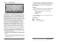
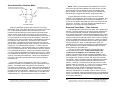
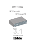
There are five LED's on the 232XS5 to indicate which port is
connected to the master port. The master port has a DB-9S female
connector and the slave ports have DB-9P male connectors. The
232XS5 requires 12Vdc at 100ma. which is provided through a
2.5mm power jack.
Chapter 1: INTRODUCTION
Checklist
Examine the shipping carton and contents for physical damage.
If damage is found, file a claim with the shipper immediately.
The RS-232 Five Port Expandable Smart Switch, Model
232XS5, allows one RS-232 host device to connect to as many as
five RS-232 devices. The switch can be controlled in three different
ways. The first way is referred to as smart switch mode or code
activated switch mode. In this mode, the switch is controlled by
sending a programmable preamble code to the "Master" port of the
232XS5. The second way the switch can be controlled is referred to
as port combiner mode. In port combiner mode, a slave port can
gain access to the master port by asserting a handshake line. If
none of the slave ports have their handshake line asserted, the
switch can be controlled using the preamble code. The third way
the switch can be controlled is the expander mode in which up to
four switches can be cascaded together to form up to 17 slave
The master port can be configured as a DTE or DCE port by an
ports.
internal switch setting. If the master port is configured as a DTE
port, the five slave ports will become DCE ports. The 232XS5
supports the following signals: TD, RD, RTS, CTS, DSR, DTR and
DCD.
The 232XS5 has an enhanced timer mode which offers special
timer features. The timer features can be used to prevent slave
devices from receiving preamble commands, inadvertently switching
from binary/graphic file transfers, and inactive slave devices from
holding control of the master port.
The 232XS5 will work with baud rates from 1200 to 115.2K bps;
7 or 8 data bits; even, odd or no parity; and 1 or 2 stop bits (7,N,1 is
not allowed).
The following equipment should be in the shipping carton:
1. RS-232 Smart Switch
2. Instruction Manual
3. Software
If any of the items above are not in the shipping carton contact
the shipper immediately.
Specifications
Model:
Size:
Power:
232XS5
3.0"w x 5.5"l x 1.0"h
12Vdc to 16Vdc @ 100ma
NOTE: The data format and rates mentioned are used to switch
the 232XS5. The communication between the devices can use
any format or data rate.
232XS5-1005 Manual
B&B Electronics Mfg Co Inc – 707 Dayton Rd - PO Box 1040 - Ottawa IL 61350 - Ph 815-433-5100 - Fax 815-433-5104
B&B Electronics Ltd – Westlink Commercial Park – Oranmore, Galway, Ireland – Ph +353 91-792444 – Fax +353 91-792445
1
2
232XS5-1005 Manual
B&B Electronics Mfg Co Inc – 707 Dayton Rd - PO Box 1040 - Ottawa IL 61350 - Ph 815-433-5100 - Fax 815-433-5104
B&B Electronics Ltd – Westlink Commercial Park – Oranmore, Galway, Ireland – Ph +353 91-792444 – Fax +353 91-792445
Chapter 2: SETUP
The 232XS5 is set up using an eight-position dipswitch and a
three-position set of jumpers. This dipswitch is used to set the
communication format, port configuration and expansion switch
address. The jumpers are used to set the smart switch/port
combiner mode, to enable/disable the enhanced features and to
enable/disable Expander mode. To change the settings on the
switch, remove the power from the unit, and remove the screws (4)
from the bottom of the 232XS5. The dipswitch is located on the top
of the PC board (side with LED’s) and is labeled “SW1.” The other
dipswitch, labeled “SW2” is used to set the second character of the
preamble. After the switches and jumpers have been set to match
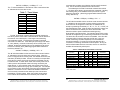
your requirements, you can put the unit back together. Table 1
shows the settings for dipswitch “SW1” and Table 2 shows the
mode settings for “JP6” jumpers.
1
0
1
0
1
0
1
0
1
X
X
X
X
X
X
X
X
X
X
2
0
0
1
1
0
0
1
1
X
X
X
X
X
X
X
X
X
X
Table 1. Communication & Port Setup
Dipswitch SW1
3 4 5 6 7 8 Setting
0 X X X X X 1200 Baud
0 X X X X X 2400 Baud
0 X X X X X 4800 Baud
0 X X X X X 9600 Baud *
1 X X X X X 19.2K Baud
1 X X X X X 38.4K Baud
1 X X X X X 57.6K Baud
1 X X X X X 115.2K Baud
X 0 X X X X 8 Data Bits *
X 1 X X X X 7 Data Bits
X X 0 X X X Parity Disabled *
X X 1 X X X Parity Enabled
X X X 0 0 X Expansion Address A *
X X X 1 0 X Expansion Address B
X X X 0 1 X Expansion Address C
X X X 1 1 X Expansion Address D
X X X X X 0 DCE master port *
X X X X X 1 DTE master port
0 = OFF
1 = ON
X = DON'T CARE
* = FACTORY DEFAULT
232XS5-1005 Manual
B&B Electronics Mfg Co Inc – 707 Dayton Rd - PO Box 1040 - Ottawa IL 61350 - Ph 815-433-5100 - Fax 815-433-5104
B&B Electronics Ltd – Westlink Commercial Park – Oranmore, Galway, Ireland – Ph +353 91-792444 – Fax +353 91-792445
3
Table 2. Mode Setup
Jumper JP6
A
B
C
Setting
ON
X
X
Enhanced Disabled *
OFF
X
X
Enhanced Enabled
X
ON
X
Smart Switch *
X
OFF ON Expansion
X
X
ON Combiner Disabled *
X
ON OFF Combiner Enabled
On = Jumper Installed Off = Jumper Removed X = DON'T CARE
* = FACTORY DEFAULT
Port Configuration
In order to determine the proper port configuration of the 232XS5, it
is necessary to have a basic understanding of the terms DCE and DTE.
RS-232 was designed, using DB-25 connectors, for connecting a DTE
(Data Terminal Equipment) device to a DCE (Data Communication
Equipment) device. Each device will have inputs on pins that
correspond to outputs on the same pins of the other device. For
example, a DTE device will transmit data out on pin 2 (on a DB-25) and
a DCE device will receive data in on pin 2 (on a DB-25). IBM PCs and
serial printers are DTE devices, modems are DCE devices.
Originally the RS-232 standard specified only a 25 pin D-sub
connector. Since then, the use of a 9 pin D-Sub supporting only a
portion of the original RS-232 signals has been used extensively,
starting with the IBM PC and migrating into other peripherals. The
pinouts for this 9 pin connector have since become the EIA/TIA 574
standard. This standard specifies a DTE device that transmits on pin 3
and receives on pin 2, with the DCE having the opposite configuration.
If an IBM PC compatible (DTE device) is going to be connected to
the 232XS5 master port, the master port should be configured as a DCE
port. If a modem (DCE device) is going to be connected to the master
port, it should be configured as a DTE port.
The master port can be configured as a DCE port (data received on
pin 3) or a DTE port (data received on pin 2) by setting dipswitch “SW1”,
position 8. To configure the master port as a DCE port, move dipswitch
“SW1”, position 8, to the "OFF" position. When the master port is
configured as a DCE port, ports A, B, C, D & E will become DTE ports
(Refer to Table 3). To configure the master port as a DTE port move
dipswitch “SW1”, position 8, to the "ON" position. When the master port
is configured as a DTE port, ports A, B, C, D & E will become DCE ports
(Refer to Table 4). Always power down the smart switch when changing
switch settings.
4
232XS5-1005 Manual
B&B Electronics Mfg Co Inc – 707 Dayton Rd - PO Box 1040 - Ottawa IL 61350 - Ph 815-433-5100 - Fax 815-433-5104
B&B Electronics Ltd – Westlink Commercial Park – Oranmore, Galway, Ireland – Ph +353 91-792444 – Fax +353 91-792445
Table 3. DCE MASTER PORT CHART
A,B,C,D & E Ports
Master Port
Signal
(DTE)
(DCE)
Pin# Direction
Description
Pin# Direction
3
Input
Transmit Data (TD)
3
Output
2
Output
Receive Data (RD)
2
Input
7
Input
Request to Send (RTS)
7
Output
8
Output
Clear to Send (CTS)
8
Input
4
Input
Data Terminal Ready (DTR)
4
Output
6
Output
Data Set Ready (DSR)
6
Input
1
Output
Data Carrier Detect (DCD)
1
Input
5
<------->
Signal Ground (SG)
5
<----->
Table 4. DTE MASTER PORT CHART
Master Port
A,B,C,D & E Ports
Signal
(DCE)
(DTE)
Pin# Direction
Description
Pin# Direction
3
Output
Transmit Data (TD)
3
Input
2
Input
Receive Data (RD)
2
Output
7
Output
Request to Send (RTS)
7
Input
8
Input
Clear to Send (CTS)
8
Output
4
Output
Data Terminal Ready (DTR)
4
Input
6
Input
Data Set Ready (DSR)
6
Output
1
Input
Data Carrier Detect (DCD)
1
Output
5
<------->
Signal Ground (SG)
5
<----->
The 232XS5 supports the following RS-232 signals: TD, RD,
SG, RTS, CTS, DCD, DSR and DTR.
NOTE: All other lines are not connected.
The Smart Switch selects port A as the default port at power up.
Serial Data Configuration
In order for the host device that is connected to the master port
to select any of the five ports, the Smart Switch must be set to
match the host's communication format. Dipswitch “SW1” is used to
select the communication format of the Smart Switch. Switch
positions 1 through 3 select the baud rate. Switch position 4 selects
7 or 8 data bits. Switch position 5 determines if parity is enabled or
disabled.
NOTE: A data format of 7 data bits, no parity and one stop is
not allowed.
Switch position 8 selects the port configuration, see section
titled "Port Configuration". Refer to Table 1. Always power down
the smart switch when changing switch settings.
RS-485 Support
RS-485 support may be
provided by adding a Model
485SD9TB RS-232 to RS-485
converter or other recommended
device to the slave ports of the
232XS5.
Port power of about 30 mA may be applied through the DTR line
(Pin 4) of the slave ports with jumper JP1-JP5. Normally, the
jumpers are set to allow DTR to pass from the master port. To
enable port power on a slave port, move the jumper from the“OFF”
to “ON” position on the corresponding JP jumper. To allow DTR to
pass from the master port to the slave port, move jumper from “ON”
to “OFF” on the corresponding JP jumper. DTR can only pass
through when the port is selected and the jumper is set to the “OFF”
position on the corresponding slave port JP jumper.
Jumper
Setting
JP1-5
“OFF”
DTR passed *
“ON”
Port Power
Table 5. Port Power Jumpers
* = FACTORY DEFAULT
232XS5-1005 Manual
B&B Electronics Mfg Co Inc – 707 Dayton Rd - PO Box 1040 - Ottawa IL 61350 - Ph 815-433-5100 - Fax 815-433-5104
B&B Electronics Ltd – Westlink Commercial Park – Oranmore, Galway, Ireland – Ph +353 91-792444 – Fax +353 91-792445
5
6
232XS5-1005 Manual
B&B Electronics Mfg Co Inc – 707 Dayton Rd - PO Box 1040 - Ottawa IL 61350 - Ph 815-433-5100 - Fax 815-433-5104
B&B Electronics Ltd – Westlink Commercial Park – Oranmore, Galway, Ireland – Ph +353 91-792444 – Fax +353 91-792445
Chapter 3: Smart Switch Operation
Smart Switch mode is selected when jumper “JP6-B” is ON
(installed). In Smart Switch mode, the 232XS5 is constantly looking
for the three character preamble code by monitoring the data that is
being received on the master port from the host device. The
232XS5 requires a three character preamble code to turn on and off
a port. The first character must be the ASCII escape character
(decimal 27). The second character is user programmable by
setting dipswitch “SW2”. “SW2” comes from the factory
programmed to the ASCII character STX (decimal 2). The third
character should be the ASCII upper case letters "A", "B", "C", "D"
or “E” (decimal 65, 66, 67, 68 or 69 respectively) to select those
ports. To turn off the selected port the third character should be the
ASCII EOT character (decimal 4). The ASCII characters and their
equivalent decimal values are listed in Appendix A.
Programming the Second Character
The second character comes programmed as the ASCII STX
character (decimal 2). You can change this to any 8-bit character
you wish by reprogramming dipswitch “SW2”. “SW2” is an eightposition switch with each position equal to a certain weight. Refer to
“Setup” for instructions on removing the cover to access “SW2”.
Table 6 shows the weight chart for “SW2”.
Table 6. Programmable Character Setting
Dipswitch SW2* WEIGHT
1
1
2
2
3
4
4
8
5
16
6
32
7
64
8
128
Example:
To turn on port B you would send the three ASCII characters:
ESC STX B
If you were writing a program in BASIC to control the Smart
Switch you would form a string like this:
*Factory Default -- ASCII “STX” character
(decimal 2), SW2 position 2 is only one ON.
SWB$ = CHR$(27) + CHR$(2) + "B"
You could then send SWB$ to select port B. Similar strings
could be used for turning on the other ports. To turn off the ports
the string might look like this:
TOFF$ = CHR$(27) + CHR$(2) + CHR$(4)
When you are done with a port you can either select a new one
directly or turn off the selected port and then turn on the next one.
We recommend that you turn off the selected port before selecting
the next one. The turn off command consists of three characters
that are nonprinting (ESC STX EOT). If port A is selected and you
send the command to select port B, all three characters (ESC STX
B) will pass through the A port since it is still selected and the letter
B will show up on your port A device. For information on preventing
command codes from being received by slave devices, refer to the
Enhance Mode section.
NOTE: There is no delay through the Smart Switch and the
data is not buffered.
232XS5-1005 Manual
B&B Electronics Mfg Co Inc – 707 Dayton Rd - PO Box 1040 - Ottawa IL 61350 - Ph 815-433-5100 - Fax 815-433-5104
B&B Electronics Ltd – Westlink Commercial Park – Oranmore, Galway, Ireland – Ph +353 91-792444 – Fax +353 91-792445
7
If you wish to use the letter "U" as the second character, which
has a decimal value of 85, you would turn on switches 1, 3, 5, and 7
(1 + 4 + 16 + 64 = 85). Caution should be used when selecting the
second character, so that by itself, or with the ESC character in front
of it, it is not a valid command to any of the devices on the port. For
instance, on some printers ESC @ is the reset command. If you
tried to use the @ symbol (decimal 64) for the second character you
could reset your printer every time the preamble code was sent.
Note also that if your communication configuration is set for 7 data
bits you cannot use the eighth bit of SW2. For a list of the ASCII
character codes and their decimal values, refer to Appendix A.
Binary File Transfer
A simple method of using the Smart Switch to transfer binary
files without the concern of it accidentally disconnecting, is to set the
file transfer at a baud rate different from the baud rate of the Smart
Switch. When transferring files at a different baud rate, the Smart
Switch will stay connected from the last preamble code.
8
232XS5-1005 Manual
B&B Electronics Mfg Co Inc – 707 Dayton Rd - PO Box 1040 - Ottawa IL 61350 - Ph 815-433-5100 - Fax 815-433-5104
B&B Electronics Ltd – Westlink Commercial Park – Oranmore, Galway, Ireland – Ph +353 91-792444 – Fax +353 91-792445
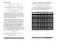
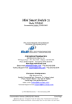
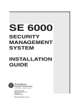
Smart Switch/Port Combiner Mode
Preamble code controls access to slave
ports if slave handshake line is not asserted Slave
Port
Master
Port
E
Handshake line of any slave
port controls access to master por
Slave
Port
A
D
C
B
Slave
Port
Slave
Port
Slave
Port
A typical application would be to have RTS and CTS tied
together on the master port. When RTS on port A is asserted, CTS
on port A will be asserted when a connection is established. If a
port is not connected to the master port, then CTS on that port will
remain low. Therefore, a port can monitor the handshake line to
determine if a connection has been established.
Port Combiner Mode
With the 232XS5 set up with a DTE master port, this mode
allows Slave Ports A-E to select the master port using the RTS input
line. It also still allows selection from the master port via the
preamble code described in the Smart Switch Only Mode section.
Jumper “JP6-C” must be OFF (removed) to be in port combiner
mode. Port combiner mode is not accessible when the unit is set up
as a port expander, so JP6-B must be ON (installed). When RTS
goes high on any of the five slave ports, it will establish a connection
from that port to the master port. This works on first-come-firstserved basis. If multiple ports have their RTS lines high, the port
that has been waiting the longest will be next to be connected to the
master port. For example (initial conditions -- no slave ports with
RTS lines asserted.), in chronological order, Port C asserts its RTS
line, Port A asserts its RTS line, Port D asserts its RTS line and then
Port C disasserts its RTS line. When Port C asserts its RTS line, a
connection will be made between the master port and Port C. When
Port C disasserts its RTS line, Port C will be disconnected and Port
A will be connected to the master port. When Port A disasserts its
RTS, Port A will be disconnected and Port D will be connected to
the master port.
For example, port A is configured as a DTE port. In order to
establish a connection to the master port, port A must set RTS high
(assert). The 232XS5 would recognize this as a prompt for
connection to the master port. The connection would be dropped as
soon as RTS on port A is brought low. Ports B-E may raise RTS at
any time to request a connection. However, if port A is connected to
the master port, any data sent from the devices on ports B-E to the
232XS5 will be lost. The 232XS5 does not have any buffering.
232XS5-1005 Manual
B&B Electronics Mfg Co Inc – 707 Dayton Rd - PO Box 1040 - Ottawa IL 61350 - Ph 815-433-5100 - Fax 815-433-5104
B&B Electronics Ltd – Westlink Commercial Park – Oranmore, Galway, Ireland – Ph +353 91-792444 – Fax +353 91-792445
NOTE: When a port is selected via the Master Port, the RTS
lines will be ignored until the Master Port sends the turn off code.
When the Master Port is selected by RTS, all preamble codes
will be ignored. The port combiner function is not available with
the Master Port configured as a DCE or in expansion mode.
9
Enhanced Timer Mode -- Timer Features
The 232XS5 has an enhanced mode, which offers special timer
features. The timer features can be used to prevent slave devices
from receiving preamble commands, inadvertent switching from
binary/graphic file transfers, and inactive slave devices from holding
control of the master port. The timer has two different modes: an
inactivity mode and an inadvertent switch mode. When in inactivity
mode, the 232XS5 will monitor the data lines. If there is no activity
for the specified time, the selected slave port will be disconnected
from the master port. When in inadvertent switch mode, the
232XS5 will ignore switching commands for the specified period of
time. After this time has expired, the selected slave port will be
disconnected from the master port.
The timer functions are enabled via a jumper setting and
through software commands. Jumper JP6-A must be OFF
(removed) for the 232XS5 to be in enhanced mode. The
software commands follow the same format as preamble codes
used for switching. There are two commands that must be sent to
the 232XS5 to set the timer functions: Set Timer Value and Set
Timer Mode. These commands require an additional byte for data.
The Set Timer Value command requires the third byte to be an
ASCII “T” character. The data byte (fourth byte) must be a value
between ASCII “0” and ASCII “9”. A value of “0” is used to disable
the timer. The time set by the Set Timer Value command
determines the length of time the 232XS5 wll wait before
disconnecting an inactive port, or the length of time it will ignore
switching commands from the master. Refer to Table 7 for timer
values. For example, sending the following string to the 232XS5 will
set the timer value to 5 seconds (assuming programmable character
is the factory default of 2).
10
232XS5-1005 Manual
B&B Electronics Mfg Co Inc – 707 Dayton Rd - PO Box 1040 - Ottawa IL 61350 - Ph 815-433-5100 - Fax 815-433-5104
B&B Electronics Ltd – Westlink Commercial Park – Oranmore, Galway, Ireland – Ph +353 91-792444 – Fax +353 91-792445
SetTV$ = CHR$(27) + CHR$(2) +”T” + “6”
The “T” tells the 232XS5 it is the set timer value command and the
“6” indicates which timer value to use.
Table 7 - Timer Values
Data
Byte
0
1
2
3
4
5
6
7
8
9
Value
timer disabled
10ms
25ms
100ms
500ms
1s
5s
30 s
1 min.
5 min.
connected to the master port (following the first-come-first-served
rule). Port C will then be placed at the “end of the line”.
If the data byte of the Set Timer Mode command is an ASCII
“1”, the timer will be setup to ignore switching commands. Sending
the following string to the 232XS5 will set up the timer to ignore
switching commands. (Assuming programmable character is the
factory default of 2).
SetTM$ = CHR$(27) + CHR$(2) +”M” + “1”
The Set Timer Mode command tells the 232XS5 whether the
time set by the Set Timer Value command will be used to determine
the time-out of an inactive port, or the length of time switching
commands are ignored. The third byte of the Set Timer Mode
command is an ASCII “M”. If the data byte (fourth byte) is an ASCII
“0”, zero (default), the timer will be setup as an inactivity timer. For
example, sending the following string to the 232XS5 will set up the
timer as an inactivity timer (assuming programmable character is
the factory default of 2).
The “M” tells the 232XS5 it is the set timer mode command and the
“1” indicates to set up the timer to ignore switching commands.
When the timer is configured in this mode, the 232XS5 will not
accept any switching commands (“A”, ”B”, ”C”, ”D”, “E”, or “EOT”) for
the specified timer value. After the timer has expired, the slave port
that is connected to the master port will be disconnected. This
feature is useful to prevent inadvertent switching during
binary/graphic type file transfers. For example (smart switch mode),
the timer is configured to ignore switching commands for 5 seconds.
The select Port D command is sent to the 232XS5. Once Port D is
connected a file of unknown data type (so file may or may not
contain a switching command sequence) is to be transferred
through the 232XS5. For a period of 5 seconds after Port D is
connected, no switching commands will be accepted. As long as
the file transfer takes less than 5 seconds, there is no chance the
232XS5 will inadvertently switch ports.
Table 8 - 232XS5 Smart Switch Mode Commands
Command Characters
Function
1st
2nd
3rd
4th
Comments
SetTM$ = CHR$(27) + CHR$(2) +”M” + “0”
The “M” tells the 232XS5 it is the set timer mode command and the
“0” indicates to set up the timer as an inactivity timer. When the
timer is configured as an inactivity timer, the 232XS5 will monitor the
data lines (TD & RD) for data. If there is no activity for the specified
timer value, the slave port that is connected to the master port will
be disconnected. In smart switch mode, the inactivity timer can be
used to prevent the preamble codes from being received by the
slave devices. In port combiner mode, the inactivity timer can be
used to prevent devices from tying up the master port. For example
(port combiner mode), all the slave ports have their handshake lines
asserted. The device on Port C has its handshake line asserted
and is currently connected to the master port, but has not been
transmitting or receiving data. When the inactivity timer expires,
Port C will be disconnected and the next slave port will then be
232XS5-1005 Manual
B&B Electronics Mfg Co Inc – 707 Dayton Rd - PO Box 1040 - Ottawa IL 61350 - Ph 815-433-5100 - Fax 815-433-5104
B&B Electronics Ltd – Westlink Commercial Park – Oranmore, Galway, Ireland – Ph +353 91-792444 – Fax +353 91-792445
11
Select Port A
ESC
X*
“A”
NU** Switching Command
Select Port B
ESC
X*
“B”
NU** Switching Command
Select Port C
ESC
X*
“C”
NU** Switching Command
Select Port D
ESC
X*
“D”
NU** Switching Command
Select Port E
ESC
X*
“E”
NU** Switching Command
Deselect Port
ESC
X*
EOT NU** Switching Command
Set Timer Value
ESC
X*
“T” “0”-”9”
Enhanced Mode
Set Timer Mode
ESC
X*
“M” “0”,”1”
Enhanced Mode
*X represents the programmable character set by dipswitch SW2
**NU = Not Used
12
232XS5-1005 Manual
B&B Electronics Mfg Co Inc – 707 Dayton Rd - PO Box 1040 - Ottawa IL 61350 - Ph 815-433-5100 - Fax 815-433-5104
B&B Electronics Ltd – Westlink Commercial Park – Oranmore, Galway, Ireland – Ph +353 91-792444 – Fax +353 91-792445
You could then send SWB$ to select port B of Expansion switch
unit address “C”. Similar strings could be used for turning on the
other ports. To turn off the ports the string might look like this:
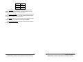
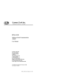
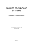
Expansion Mode
Slave
Port
Master
Port
Expansion
Port
Slave
Slave
Port
Port
E
E
A
D
C
B
Slave
Port
Slave
Port
Address D
Expansion
Port
Slave
Slave
Port
Port
A
D
C
B
Slave
Port
Slave
Port
Address C
Expansion
Port
Slave
Slave
Port
Port
Slave
Port
E
A
D
C
B
A
B
Slave
Port
Slave
Port
Slave
Port
Slave
Port
E
D
Address A C
Address B
TOFF$ = CHR$(27) + CHR$(2) + CHR$(4)
Slave
Port
When you are done with a port you can either select a new one
directly or turn off the selected port and then turn on the next one.
For information on preventing command codes from being received
by slave devices, refer to the Enhanced Mode section.
17-Port Cascaded Expansion Mode
The number of serial ports on the 232XS5 can easily be
expanded to a maximum of seventeen ports. Up to four 232XS5
units may be cascaded in expander mode. Each unit address adds
four additional serial ports to the five on unit address “A”. Port C is
used as the expansion port that connects to the follow-on masterport for switch units addressed “B” thru “D”. Expansion Switch unit
address “A” is the last Switch in the chain.
Expander mode is selected when jumper “JP6-B” is OFF
(removed.) In Expander mode, the 232XS5 is constantly looking for
a four character preamble code by monitoring the data that is being
received on the master port from the host device. The 232XS5
requires a four character preamble code to turn on and off a port.
The first character must be the ASCII escape character (decimal
27). The second character is user programmable by setting
dipswitch “SW2”. “SW2” comes from the factory programmed to the
ASCII character STX (decimal 2). The third character is the
Expansion Switch Unit Address character “A” through “D”. The
fourth character should be the ASCII upper case letters "A", "B", "C",
"D" or “E” (decimal 65, 66, 67, 68 or 69 respectively) to select those
ports. To turn off the selected port the third character should be the
ASCII EOT character (decimal 4). For instance, to turn on port B of
Expansion Switch unit address C, you would send:
ESC STX C B
Table 9 - 232XS5 Expander Mode Commands
Command Characters
Function
1st
2nd
3rd
4th
Comments
Select Port A
ESC
X*
“A”
“A”
Address A
Select Port B
ESC
X*
“A”
“B”
Address A
Select Port C
ESC
X*
“A”
“C”***
Address A
Select Port D
ESC
X*
“A”
“D”
Address A
Select Port E
ESC
X*
“A”
“E”
Address A
Select Port A
ESC
X*
“B”
“A”
Address B
Select Port B
ESC
X*
“B”
“B”
Address B
Select Port D
ESC
X*
“B”
“D”
Address B
Select Port E
ESC
X*
“B”
“E”
Address B
Select Port A
ESC
X*
“C”
“A”
Address C
Select Port B
ESC
X*
“C”
“B”
Address C
Select Port D
ESC
X*
“C”
“D”
Address C
Select Port E
ESC
X*
“C”
“E”
Address C
Select Port A
ESC
X*
“D”
“A”
Address D
Select Port B
ESC
X*
“D”
“B”
Address D
Select Port D
ESC
X*
“D”
“D”
Address D
Select Port E
ESC
X*
“D”
“E”
Address D
Deselect Port
ESC
X*
EOT NU** Switching Command
Set Timer Value
ESC
X*
“T” “0”-”9”
Enhanced Mode
Set Timer Mode
ESC
X*
“M” “0”,”1”
Enhanced Mode
* X represents the programmable character set by dipswitch SW2
** NU = Not Used
***Port C is used as the expansion port for unit addresses B thru D.
If you were writing a program in BASIC to control the Smart
Switch you would form a string like this:
SWB$ = CHR$(27) + CHR$(2) + "C" + ”B”
232XS5-1005 Manual
B&B Electronics Mfg Co Inc – 707 Dayton Rd - PO Box 1040 - Ottawa IL 61350 - Ph 815-433-5100 - Fax 815-433-5104
B&B Electronics Ltd – Westlink Commercial Park – Oranmore, Galway, Ireland – Ph +353 91-792444 – Fax +353 91-792445
13
14
232XS5-1005 Manual
B&B Electronics Mfg Co Inc – 707 Dayton Rd - PO Box 1040 - Ottawa IL 61350 - Ph 815-433-5100 - Fax 815-433-5104
B&B Electronics Ltd – Westlink Commercial Park – Oranmore, Galway, Ireland – Ph +353 91-792444 – Fax +353 91-792445
Chapter 4: SOFTWARE
Introduction
The Smart Switch software allows the user to change Smart Switch ports
on three different modules (232XSS, 232XS5, PortMUX). The Smart Switch
software is designed as diagnostic software for the above modules. It will
allow you a Module by Module connection to the individual port.
Should the user wish to change the Module choice to another there is a
Module menu choice with the three support Module types (PortMUX,
232XSS, and 232XS5). After changing the Module the user will be prompted
to restart the Smart Switch software to reset the connection.
Default Values
Installation
The software for the Smart Switch is designed to be run in any Windows
environment. To install it on your hard drive follow these steps:
When you start Smart Switch software, the default values will be used.
The default values are:
Description
Port Address
Baud Rate
Data Bits
Second Character
Method One
• Install the software media.
• Select Settings from the Start Button and click on Control Panel.
• In the Control Panel Window, double click on the Add/Remove
Programs.
• Click on the “Install” button.
• Follow the instructions of the setup program.
Default Value
COM 1
9600
8 Data Bits
2 = STX (CTRL B)
Selecting Ports
Method Two
Install the software media.
Select Programs from the Start Button and click on Windows Explorer.
Click on the drive containing the software.
Double click on the file “Setup.exe”.
Follow the instructions of the setup program.
•
•
•
•
•
To select a port the user need only pick from the Menu-> Comport the
comport to which the device is attached. The Smart Switch program
supports comports 1 through 6. If the port exists but does not have a smart
switch device attached, SS will not detect it. The SS software will only detect
invalid/undefined comports.
Parameters
The following file will be located on your hard drive:
•
•
•
•
SS.EXE - The executable file for the Smart Switch.
FILES.LST Contains a list and description of files installed on your hard
drive.
READ.ME Contains corrections and additions to the printed users
manual.
HISTORY.LST Contains a historic description of the product.
The Port Address is the address where the serial communications port
is located. If this is unknown you can use the program PORTFIND.EXE
which is located in the provided software. To use PORTFIND.EXE:
If you installed the software on your hard drive see the Installation
section:
• Type C: and press the ENTER key.
• Type CD\SS\UTIL and press the ENTER key.
• Type PORTFIND and press the ENTER key.
The result will be similar to the following:
Setup
PortFind V1.03 - © 1991 B&B Electronics - All Rights Reserved.
Slave 8259 present can't use shared IRQ2
COM1 at address 03F8h is set for IRQ4 and is a 8250A or 16450 type UART
COM2 at address 02F8h is set for IRQ3 and is a 8250A or 16450 type UART
LPT1 at address 0378h found
The Smart Switch program will prompt the user for the Module that is in
use the first time that the software is run. After the proper Module (i.e.
PortMUX, 232XS5,etc.) is selected then a window specific to that Module will
appear and the user may personalize communication parameters as per
their specific needs. Comport, Baud Rate, and Data Bits (Character Mode,
and User Defined Character may also be set for 232XSS and 232XS5
Modules).
232XS5-1005 Manual
B&B Electronics Mfg Co Inc – 707 Dayton Rd - PO Box 1040 - Ottawa IL 61350 - Ph 815-433-5100 - Fax 815-433-5104
B&B Electronics Ltd – Westlink Commercial Park – Oranmore, Galway, Ireland – Ph +353 91-792444 – Fax +353 91-792445
15
Some of the typical port addresses are as follows:
16
232XS5-1005 Manual
B&B Electronics Mfg Co Inc – 707 Dayton Rd - PO Box 1040 - Ottawa IL 61350 - Ph 815-433-5100 - Fax 815-433-5104
B&B Electronics Ltd – Westlink Commercial Park – Oranmore, Galway, Ireland – Ph +353 91-792444 – Fax +353 91-792445
Port
COM 1
COM 2
COM 3
COM 4
Address
03F8h
02F8h
03E8h
02E8h
The Baud Rate is the speed at which communication takes place
between the PC and the Smart Switch. It must be specified so that it is
equal to SW1 – positions 1 – 3 on the Smart Switch.
The Number of Data Bits is the length of each character that gets sent
from the PC to the Smart Switch. This value must be specified so that it is
equal to SW1 – position 4 on the Smart Switch.
The Module must be set so that it is equal to the Smart Switch Module
which you are using (i.e. PortMUX if you are using a PortMUX).
The User Defined Character must be set so that it is equal to SW2 on
the Smart Switch.
232XS5-1005 Manual
B&B Electronics Mfg Co Inc – 707 Dayton Rd - PO Box 1040 - Ottawa IL 61350 - Ph 815-433-5100 - Fax 815-433-5104
B&B Electronics Ltd – Westlink Commercial Park – Oranmore, Galway, Ireland – Ph +353 91-792444 – Fax +353 91-792445
17
18
232XS5-1005 Manual
B&B Electronics Mfg Co Inc – 707 Dayton Rd - PO Box 1040 - Ottawa IL 61350 - Ph 815-433-5100 - Fax 815-433-5104
B&B Electronics Ltd – Westlink Commercial Park – Oranmore, Galway, Ireland – Ph +353 91-792444 – Fax +353 91-792445
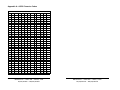
Appendix A: ASCII Character Codes
DECIMAL to HEX to ASCII CONVERSION TABLE
DEC HEX ASCII KEY DEC HEX ASCII DEC HEX ASCII DEC HEX ASCII
0
0
NUL
ctrl @
32
20
SP
64
40
@
96
60
`
1
1
SOH
ctrl A
33
21
!
65
41
A
97
61
a
2
2
STX
ctrl B
34
22
“
66
42
B
98
62
b
3
3
ETX
ctrl C
35
23
#
67
43
C
99
63
c
4
4
EOT
ctrl D
36
24
$
68
44
D
100
64
d
5
5
ENQ
ctrl E
37
25
%
69
45
E
101
65
e
6
6
ACK
ctrl F
38
26
&
70
46
F
102
66
f
7
7
BEL
ctrl G
39
27
'
71
47
G
103
67
g
8
8
BS
ctrl H
40
28
(
72
48
H
104
68
h
9
9
HT
ctrl I
41
29
)
73
49
I
105
69
i
10
A
LF
ctrl J
42
2A
*
74
4A
J
106
6A
j
11
B
VT
ctrl K
43
2B
+
75
4B
K
107
6B
k
12
C
FF
ctrl L
44
2C
,
76
4C
L
108
6C
l
13
D
CR
ctrl M
45
2D
-
77
4D
M
109
6D
m
14
E
SO
ctrl N
46
2E
.
78
4E
N
110
6E
n
15
F
SI
ctrl O
47
2F
/
79
4F
O
111
6F
o
16
10
DLE
ctrl P
48
30
0
80
50
P
112
70
p
17
11
DC1
ctrl Q
49
31
1
81
51
Q
113
71
q
18
12
DC2
ctrl R
50
32
2
82
52
R
114
72
r
19
13
DC3
ctrl S
51
33
3
83
53
S
115
73
s
20
14
DC4
ctrl T
52
34
4
84
54
T
116
74
t
21
15
NAK
ctrl U
53
35
5
85
55
U
117
75
u
22
16
SYN
ctrl V
54
36
6
86
56
V
118
76
v
23
17
ETB
ctrl W
55
37
7
87
57
W
119
77
w
24
18
CAN
ctrl X
56
38
8
88
58
X
120
78
x
25
19
EM
ctrl Y
57
39
9
89
59
Y
121
79
y
26
1A
SUB
ctrl Z
58
3A
:
90
5A
Z
122
7A
z
27
1B
ESC
ctrl [
59
3B
;
91
5B
[
123
7B
{
28
1C
FS
ctrl \
60
3C
<
92
5C
\
124
7C
|
29
1D
GS
ctrl ]
61
3D
=
93
5D
]
125
7D
}
30
1E
RS
ctrl ^
62
3E
>
94
5E
^
126
7E
~
31
1F
US
ctrl _
63
3F
?
95
5F
_
127
7F
DEL
232XS-1005 Manual
B&B Electronics -- PO Box 1040 -- Ottawa, IL 61350
PH (815) 433-5100 -- FAX (815) 433-5104
A-1
A-2
Appendix A
232XS5-1005 Manual
B&B Electronics -- PO Box 1040 -- Ottawa, IL 61350
PH (815) 433-5100 -- FAX (815) 433-5104
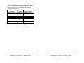
Chart 3. Modem DB25 Connector to Master Port
Appendix B: Cable Charts
All charts will indicate if the Master Port of the 232XS5 should
be configured as a DCE port or a DTE port. Refer to the Port
Configuration section of the manual for information on Master Port
configurations.
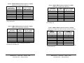
Chart 1. IBM PC DB25 Connector to Master Port
IBM PC
232XS5
Serial Port
Signal
Master Port (DCE)
DB25 Connector
Direction
DB9 Connector
2
----------->
3
3
<----------2
4
----------->
7
5
<----------8
6
<----------6
7
<--------->
5
8
<----------1
20
----------->
4*
* Pins are tied together inside the 232XS5, they are not connected
to ports A, B, C, D, or E.
Chart 2. IBM PC DB9 Connector to Master Port
IBM PC
232XS5
Serial Port
Signal
Master Port (DCE)
DB9 Connector
Direction
DB9 Connector
1
<----------1
2
<----------2
3
----------->
3
4
----------->
4
5
<--------->
5*
6
<----------6
7
----------->
7
8
<----------8
* Pins are tied together inside the 232XS5, they are not
connected to ports A, B, C, D, or E.
232XS5-1005 Manual
Appendix B
B&B Electronics -- PO Box 1040 -- Ottawa, IL 61350
PH (815) 433-5100 -- FAX (815) 433-5104
B-1
Async Modem
232XS5
Serial Port
Signal
Master Port (DTE)
DB25 Connector
Direction
DB9 Connector
2
<----------3
3
----------->
2
4
<----------6
5
----------->
4
7
<--------->
5*
8
----------->
8
20
<----------7
* Pins are tied together inside the 232XS5, they are not
connected to ports A, B, C, D, or E.
NOTE: When connecting a DTE device to ports A, B, C, D or E of
the smart switch, refer to Charts 8 and 9.
Chart 4. IBM PC DB25 Connector to Ports A - E (DTE)
Master port configured as a DCE port.
IBM PC
232XS5
Serial Port
Signal
Ports A - E (DTE)
DB25 Connector
Direction
DB9 Connector
2
----------->
2
3
<----------3
4
----------->
8
5
<---------7
6
<---------6
7
<--------->
5
8
<----------4*
20
----------->
4*
* Pins are tied together inside the 232XS5, they are not connected
to the master port.
B-2
Appendix B
232XS5-1005 Manual
B&B Electronics -- PO Box 1040 -- Ottawa, IL 61350
PH (815) 433-5100 -- FAX (815) 433-5104
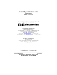
Chart 5. IBM PC DB25 Connector to Ports A - E (DCE)
Master port configured as a DTE port.
IBM PC
232XS5
Serial Port
Signal
Ports A - E (DCE)
DB25 Connector
Direction
DB9 Connector
2
----------->
3
3
<----------2
4
----------->
7
5
<----------8
6
<----------6
7
<--------->
5
8
<----------4*
20
----------->
4*
* Pins are tied together inside the 232XS5, they are not connected
to the master port.
Chart 6. IBM PC DB9 Connector to Ports A - E (DTE)
Master port configured as a DCE port.
IBM PC
232XS5
Serial Port
Signal
Ports A - E (DTE)
DB9 Connector
Direction
DB9 Connector
1
<----------4*
2
<----------3
3
----------->
2
4
----------->
6
5
<--------->
5
6
<----------4*
7
----------->
8
8
<----------7
Chart 8. IBM PC DB25 Connector to Ports A - E (DCE)
Master port configured as a DTE port with a modem connected
(see Chart 3).
IBM PC
232XS5
Serial Port
Signal
Ports A - E (DCE)
DB25 Connector
Direction
DB9 Connector
2
----------->
3
3
<----------2
4
----------->
6
5
<----------4*
6
<----------4*
7
<--------->
5
8
<----------8
20
----------->
7
* Pins are tied together inside the 232XS5, they are not connected
to the master port.
* Pins are tied together inside the 232XS5, they are not
connected to the master port.
232XS5-1005 Manual
Appendix B
B&B Electronics -- PO Box 1040 -- Ottawa, IL 61350
PH (815) 433-5100 -- FAX (815) 433-5104
Chart 7. IBM PC DB9 Connector to Ports A - E (DCE)
Master port configured as a DTE port.
IBM PC
232XS5
Serial Port
Signal
Ports A - E (DCE)
DB9 Connector
Direction
DB9 Connector
1
<----------4*
2
<----------2
3
----------->
3
4
----------->
4*
5
<--------->
5
6
<----------6
7
----------->
7
8
<----------8
* Pins are tied together inside the 232XS5, they are not connected
to the master port.
B-3
B-4
Appendix B
232XS5-1005 Manual
B&B Electronics -- PO Box 1040 -- Ottawa, IL 61350
PH (815) 433-5100 -- FAX (815) 433-5104
Chart 9. IBM PC DB9 Connector to Ports A - E (DCE)
Master port configured as a DTE port with a modem
connected (see Chart 3).
IBM PC
232XS5
Serial Port
Signal
Ports A - E (DCE)
DB9 Connector
Direction
DB9 Connector
3
----------->
3
2
<----------2
7
----------->
6
8
<----------4*
6
<----------4*
5
<--------->
5
1
<----------8
4
----------->
7
* Pins are tied together inside the 232XS5, they are not
connected to the master port.
232XS5-1005 Manual
Appendix B
B&B Electronics -- PO Box 1040 -- Ottawa, IL 61350
PH (815) 433-5100 -- FAX (815) 433-5104
B-5
B-6
Appendix B
232XS5-1005 Manual
B&B Electronics -- PO Box 1040 -- Ottawa, IL 61350
PH (815) 433-5100 -- FAX (815) 433-5104