1
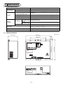
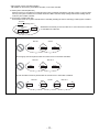
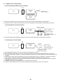
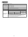
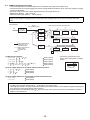
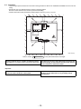
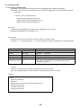
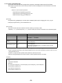
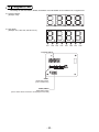
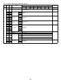
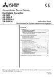
Air-Conditioner Network System
Centralized Controller
GB-50ADA-A
GB-50ADA-J
Installation/Instructions Manual
Contents
Page
• Safety notes are marked with
WARNING or
CAUTION,
depending on the severity of possible
consequences that may result when the
instructions are not followed exactly as
stated.
Proper installation is important for your
safety and proper functioning of the units.
Thoroughly read the following safety
precautions prior to installation.
To ensure safety and proper operation of the
unit, the unit should only be installed by
qualified personnel.
After reading this manual, pass the manual on to the end
user to retain for future reference.
The users should keep this manual for future reference and
refer to it as necessary. This manual should be made
available to those who repair or relocate the units. Make
sure that the manual is passed on to any future air
condition system users.
Safety Precautions............................................ 2
1. Introduction ............................................... 5
1-1. Parts names and functions .............. 5
1-2. Monitor and operation of the air
conditioners...................................... 6
1-3. About “Group” and “Block” ............... 6
2. Parts List ................................................... 6
3. Specifications ............................................ 7
3-1. Product Specifications ..................... 7
3-2. External dimensions......................... 7
3-3. Supplying power to the M-NET
transmission lines ............................ 8
4. System configuration ................................ 9
4-1. Setting M-NET address for
various devices .............................. 10
4-2. M-NET system setting example ..... 12
5. Installation............................................... 13
5-1. Field-supplied parts........................ 13
5-2. M-NET transmission line length ..... 14
5-3. Installation...................................... 15
6. Wiring connections.................................. 16
6-1. Installing and uninstalling the cover ..16
6-2. Connecting the power cable and
protective earth cable..................... 16
6-3. Connecting the M-NET
transmission line ............................ 17
6-4. Connecting the LAN cable ............. 18
7. Initial settings .......................................... 19
7-1. IP address and network settings.... 20
8. Product features...................................... 21
9. Test run................................................... 23
9-1. Batch operation/Stop (error reset)
switches ......................................... 23
9-2. Service LED display....................... 23
10. External input/output ............................... 24
10-1. External signal input function ......... 24
10-2. External signal output function....... 25
11. Copy to USB memory and read from USB
memory ................................................... 26
11-1. Switch setting................................. 27
11-2. Operational data ............................ 28
12. 7-segment LED ....................................... 30
12-1. 7-segment LED display and switch
settings........................................... 31
13. Error code list .......................................... 32
Safety Precautions
• Thoroughly read the following safety precautions prior to installation.
• Observe these precautions carefully to ensure safety.
WARNING
Indicates a risk of death or serious injury.
CAUTION
Indicates a risk of injury or structural damage.
●Nomenclature
(Prohibited actions)
(Do not touch)
(No water)
(No wet hands)
(Fire hazards) (Electric shock hazards) (Injury hazards)
(Important actions) (Grounding required)
• After reading this manual, pass the manual on to the end user to retain for future reference.
• The users should keep this manual for future reference and refer to it as necessary. This manual should be made available to those
who repair or relocate the units. Make sure that the manual is passed on to any future air condition system users.
All electric work must be performed by qualified personnel.
General precautions
WARNING
To reduce the risk of injury or electric shock, before
spraying a chemical around the controller, stop the
operation and cover the controller.
Do not install the controller in a place where large amounts
of oil, steam, organic solvents, or corrosive gases, such as
sulfuric gas, are present or where acidic/alkaline solutions
or sprays are used frequently. These substances can
compromise the performance of the controller or cause
certain components of the controller to corrode, which can
result in electric shock, malfunctions, smoke, or fire.
To reduce the risk of injury or electric shock, stop the
operation and switch off the power supply before
cleaning, maintaining, or inspecting the controller.
To reduce the risk of shorting, current leakage, electric
shock, malfunctions, smoke, or fire, do not wash the
controller with water or any other liquid.
Properly install all required covers to keep moisture and
dust out of the controller. Dust accumulation and water
can cause electric shock, smoke, or fire.
To reduce the risk of electric shock, malfunctions,
smoke or fire, do not operate the switches/buttons or
touch other electrical parts with wet hands.
To reduce the risk of injury, keep children away while
installing, inspecting, or repairing the controller.
CAUTION
To reduce the risk of fire or explosion, do not place
flammable materials or use flammable sprays around
the controller.
To reduce the risk of damage to the controller, do not
directly spray insecticide or other flammable sprays on
the controller.
Do not touch the display panel, switches, or buttons
with a sharp object.
To avoid injury from broken glass, do not apply excessive force on the glass parts.
To reduce the risk of injury, wear protective gear when
working on the controller.
Always replace a fuse with the correct current rating.
Using a fuse with the wrong rating or substituting or a
copper wire may cause a fire or explosion.
To reduce the risk of injury and electric shock, avoid
contact with sharp edges of certain parts.
-2-
Precautions during installation
WARNING
Do not install the controller where there is a risk of
leaking flammable gas.
If flammable gas accumulates around the controller, it
may ignite and cause a fire or explosion.
Take appropriate safety measures against earthquakes
to prevent the controller from causing injury.
To prevent injury, install the controller on a flat surface
strong enough to support its weight.
Properly dispose of the packing materials. Plastic bags
pose suffocation hazard to children.
CAUTION
To reduce the risk of shorting, current leakage, electric
shock, malfunctions, smoke, or fire, do not install the
controller in a place exposed to water or in a condensing environment.
Controller must be installed by qualified personnel
according to the instructions detailed in the Installation
Manual.
Improper installation may result in electric shock or fire.
Precautions during wiring
WARNING
To reduce the risk of damage to the controller, malfunctions, smoke, or fire, do not connect the power cable to
the signal terminal block.
Properly secure the cables in place and provide
adequate slack in the cables so as not to stress the
terminals.Improperly connected cables may break,
overheat, and cause smoke or fire.
To reduce the risk of injury or electric shock, switch off
the main power before performing electrical work.
All electric work must be performed by a qualified
electrician according to the local regulations, standards,
and the instructions detailed in the Installation
Manual.Capacity shortage to the power supply circuit or
improper installation may result in malfunction, electric
shock, smoke, or fire.
Install an electric leakage breaker and a residual
current circuit breaker on the power supply.
Use properly rated breakers and fuses (breaker, local
switch <switch + fuse>, no-fuse breaker).The use of a
breaker with a breaking capacity greater than the
specified capacity may cause electric shock, malfunctions, smoke, or fire.
To reduce the risk of current leakage, overheating,
smoke, or fire, use properly rated cables with adequate
current carrying capacity.
Proper grounding must be provided by a licensed
electrician.
Do not connect the grounding wire to a gas pipe, water
pipe, lightning rod, or telephone wire. Improper grounding may result in electric shock, smoke, fire, or malfunction due to electrical noise interference.
CAUTION
To reduce the risk of electric shock, shorting, or
malfunctions, keep wire pieces and sheath shavings out
of the terminal block.
To reduce the risk of shorting, current leakage, electric
shock, or malfunctions, keep the cables out of contact
with controller edges.
Precautions for moving or repairing the controller
WARNING
The controller should be repaired or moved only by qualified
personnel. Do not disassemble or modify the controller.
Improper installation or repair may cause injury, electric
shock, or fire.
CAUTION
To reduce the risk of shorting, electric shock, fire, or
malfunction, do not touch the circuit board with tools or
with your hands, and do not allow dust to accumulate
on the circuit board.
-3-
Additional precautions
To avoid damage to the controller, use appropriate tools to
install, inspect, or repair the controller.
To avoid damage to the controller, do not overtighten the
screws.
This controller is designed for exclusive use with the Building
Management System by Mitsubishi Electric. The use of this
controller for with other systems or for other purposes may
cause malfunctions.
To avoid damage to the controller, do not make holes on the
controller cover.
Take appropriate measures against electrical noise interference when installing the air conditioners in hospitals or
facilities with radio communication capabilities.
Inverter, high-frequency medical, or wireless communication
equipment as well as power generators may cause the air
conditioning system to malfunction. Air conditioning system
may also adversely affect the operation of these types of
equipment by creating electrical noise.
To avoid malfunctions, do not bundle power cables and
signal cables together, or place them in the same metallic
conduit.
To avoid deformation and malfunction, do not install the
remote controller in direct sunlight or where the ambient
temperature may exceed 55ºC (131ºF) or drop below
-10ºC (14ºF).
Do not install the controller on the Control panel door.
Vibrations or shocks to the controller may damage the
controller or cause the controller to fall.
To prevent unauthorized access, always use a security
device such as a VPN router when connecting to the
Internet.
-4-
1 Introduction
GB-50ADA-A and GB-50ADA-J are centralized controllers that can be operated over the Web.
Any connected air conditioning systems can be operated or monitored over the Web using browser software.
Refer to the Web browser operation manual (separate volume) for how to use this functions.
This manual covers the settings that can be made or functions that can be displayed only on the body of GB-50ADA-A or
GB50ADA-J.
Hereinafter, GB-50ADA-A and GB-50ADA-J, unless otherwise specified, will be called “GB-50ADA.”
1-1. Parts names and functions
1-1.
Error LED
1-1.
Error
Serial number :
Ver. :
DB No. :
M-NET LED
M-NET
LAN LED
CN5 CN4
I/O Serial
M-NET Terminal
block(M3.5)
LINK/ACT LAN
LAN
Power source 100-240VAC
Terminal block(M3.5)
MODEL :
Serial number :
External input/output
terminal(CN5)
-5-
1-2. Monitor and operation of the air conditioners
To monitor and operate the air conditioners, license for “GB-50ADA Basic License Pack” or “Web Monitor” must be purchased and
registered. Purchase the license from the dealer, and register on the Initial Setting Web or on the Web for Monitor and Operation.
Refer to Web Browser Operation Manual for monitor and operation of air conditioners.
The format in which the Web page address for each GB-50ADA is expressed on the Web browser, as well as the default user name
and password are shown below.
http : // [IP address of the GB-50ADA]/administrator.html
Note: For example, type http : //192.168.1.1/administrator.html if the GB-50ADA IP address is [192.168.1.1].
Note
User
Default user name
Default password
Managers
administrator
admin
With the registration of “GB-50ADA Basic License Pack,” Web Monitor,” “Annual Schedule, Weekly Schedule,” “Sending
Error Mail,” and “Maintenance Tool Advanced” functions will be available.
Consult the dealer for information on other functions that require a license (i.e. “Energy Management License Pack” “Personal Web”).
Initial settings such as making group changes are covered in the Initial Setting Web manual.
The format in which the Web page address for each GB-50ADA is expressed on the Web browser, as well as the default user
name and password are shown below.
http : / /[IP address of the GB-50ADA]/g-50/administrator.html
Note: For example, type “http : // 192.168.1.1/g-50/administrator.html” if the GB-50ADA IP address is
[192.168.1.1].
User
Default user name
Default password
Maintenance user
initial
init
1-3. About “Group” and “Block”
The terms “Group” and “Block” used in this manual are defined as follows.
Group: Group is a group of air conditioning units and controllers and is the smallest unit that the GB-50ADA can control.
The maximum number of units that each group can contain is 16.
Block: Block is a group of groups. Energy-save and peak-cut settings are made for each block.
2 Parts List
The manual and the parts listed below are included in the box.
No.
Description
Qty.
1
Centralized controller
1
2
Installation/Instruction Manual (this Manual)
1
3
Instruction Book
(Web browser for Initial Settings)
1
4
Instruction Book
(Web browser for System maintenance engineer)
1
-6-
3 Specifications
3-1. Product Specifications
Items
Power source
Interface
Specifications
Rated input
100-240VAC ±10% 0.4-0.3A 50/60Hz
Fuse
250VAC 3.15A Time-delay Type (IEC127-2.S.S.5)
Rated output of the power supply
to M-NET transmission lines
22-30VDC
External input/output
12VDC or 24VDC (requires an external power supply)
LAN
100BASE-TX/10BASE-T
USB
Ambient
conditions
Temperature
USB1.1 supported
Operating
-10~55°C [14~131°F]
temperature range
Storage
-20~60°C [-4~140°F]
temperature range
Humidity
30 ~ 90%RH (Non-condensing)
Dimensions
217 (H) × 250 (W) × 97.2 (D) mm
[8-9/16 (H) × 9-7/8 (W) × 3-7/8 (D) in.]
Weight
2.6kg [5-3/4 lbs.]
Installation conditions
Inside the metal control panel (indoor)
3-2. External dimensions
Unit: mm (in.)
5 (3/16)
250 (9-7/8)
97.2 (3-7/8)
155 (6-1/8)
Serial number :
Ver. :
DB No. :
M-NET
CN5 CN4
I/O Serial
MODEL :
Serial number :
-7-
LINK/ACT LAN
217 (8-9/16)
204.5 (8-1/16)
Error
3-3. Supplying power to the M-NET transmission lines
GB-50ADA has a built-in function to supply power to the M-NET transmission line. (power supply coefficient: 6)
The total power consumption coefficient of the system controller and M-NET remote controller to which GB-50ADA supplies
power (See table 1) should not exceed the power supply coefficient of GB-50ADA, which is six.
Table 1 Power consumption coefficient of the controller
System controller
M-NET remote controller
System remote controller
ON/OFF remote controller Schedule timer
Group remote controller
ME remote controller
LOSSNAY remote controller
1
0.5
0.25
Table 2 No. of connectable units
System controller
M-NET remote controller
System remote controller
ON/OFF remote controller Schedule timer
Group remote controller
ME remote controller
LOSSNAY remote controller
6 units
12 units
24 units
Table 3 No. of connectable units in systems with various combinations of remote controllers
V: connectable
Total number of ON/OFF remote controllers
Total number of system remote controllers,
schedule timers, and group remote
controllers combined.
Note
0
1
2
3
4
5
6
0
V
V
V
V
V
V
V
1
V
V
V
V
V
V
2
V
V
V
V
V
V
3
V
V
V
V
V
4
V
V
V
V
V
5
V
V
V
V
6
V
V
V
V
7
V
V
V
8
V
V
V
9
V
V
10
V
V
11
V
12
V
When connecting both GB-50ADA and BAC-HD150 (BM ADAPTER) to the same M-NET system, certain
restrictions apply.
Consult your dealer for details.
-8-
4 System configuration
The figure below only shows the transmission line connections. Power supply lines are omitted.
Do not connect directly to the Internet. When
connecting to the Internet, use a security
device such as a VPN router.
Indoor unit
LAN
Centralized controller
GB-50ADA
TB3
Local remote controller
M-NET transmission line
K transmission line
M-NET
outdoor unit
MA remote controller
Group 1
TB7
Group 2
TB3
003
MA
M-NET
outdoor unit
R2
004
MA
BC controller
Group 3
TB7
The numbers in the
indicate the address No.
LOSSNAY
TB3
ME
Mr.Slim
outdoor unit
Mr.Slim
outdoor unit
M-NET adapter
Group 4
Group 5
MA
MA
K control
outdoor unit
Group 13
TB7
K transmission converter
213
Group 15
TB3
K
13
K
Model:PAC-SC25KAA
-9-
15
4-1. Setting M-NET address for various devices
The same address cannot be used more than once within the same M-NET system of GB-50ADA.
(K-control units and K-control remote control addresses are excluded.)
Address setting method
Indoor unit
Outdoor unit
Auxiliary outdoor unit
(BC controller etc.)
OA processing unit/
LOSSNAY
Mr.Slim outdoor unit
M-NET remote controller
MA remote controller
Sub system controller
DIDO controller
(PAC-YG66DCA)
PI controller
(PAC-YG60MCA)
AI controller
(PAC-YG63MCA)
K-control indoor unit
K-control remote
controller
K-transmission converter
Assign the lowest address to the main indoor unit in the group, and assign sequential
addresses to the rest of the indoor units in the same group.
Assign an address that equals the lowest indoor unit address in the same refrigerant
group plus 50.
Assign an address that equals the address of the outdoor unit in the same refrigerant
system plus 1.
Assign an arbitrary but unused address to each of these units after assigning an
address to all indoor units.
Make the settings in the same way as with the indoor units. Requires an M-NET
adapter (sold separately).
Assign an address that equals the address of the main indoor unit with the lowest
address in the group plus 100.
Add 150 in stead of 100 to set the address for a sub remote controller.
Address setting is not required.
Connection of two remote controllers requires the main/sub setting for each
controller to be made.
Assign an address that equals the group number of the smallest controlled group
plus 200.
Assign an arbitrary but unused address to the controller after completing the address
setting for the units with an address between 1 and 50.
The number of controllable units changes with the number of channels used.
Assign an arbitrary but unused address to the controller after completing the address
setting for the units with an address between 1 and 50.
Assign an arbitrary but unused address to the controller after completing the address
setting for the units with an address between 1 and 50.
Assign an address to all indoor units connected to the M-NET lines (incl. LOSSNAY
units) first, and then assign addresses to the K-control indoor units, starting with the
address after the last address.
Assign an address as the lowest address of the K-control indoor units in the same
group.
Assign an address that equals the lowest K-control indoor unit address plus 200.
M-NET
address
1 ~ 50
51 ~ 100
52 ~ 100
1 ~ 50
1 ~ 50
101 ~ 200
–
201 ~ 250
1 ~ 50
1 ~ 50
1 ~ 50
1 ~ 50
1 ~ 50
201 ~ 250
Important
Check that the setting for the central control switch SW2-1 on the M-NET outdoor unit is set to “ON.”
(Refer to the outdoor unit Installation Manual for the detailed information about dip switch settings.)
Note the following when using a K-transmission converter (model: PAC-SC25KAA) to control the K-control units.
Refer to the K-transmission converter Installation Manual for details.
1 Be sure to set the GB-50ADA address to “000.”
2 Set the “K-transmission converter connection setting” (to be set from a Main controller) to ON (with a
connection to K-transmission converter).
When this setting is set to ON, an address field will appear. Enter the K-transmission converter address in the
field.
3 Assign addresses to the K-control air conditioners so that they are larger than the addresses that are
assigned to the M-control indoor units.
4 Make the group settings for K-control units so that the group number equals the lowest address of the indoor
units within the group.
5 If the K-control Y series units and other types of units (K-control Mr. Slim) are used in combination, a relay
board is required. The K-control Y series of units and other types of units cannot be connected to the same
transmission line.
6 A relay board may be required, depending on the number of K-control units and the length of transmission
lines. Refer to the System Design Manual (control version) for details.
7 LOSSNAY units that are connected to the general K-control kit cannot be connected.
8 Remote controller addresses is not required in the group setting for the K-control models.
Note
A-control jet burner models cannot be controlled.
Some models cannot be controlled.
Main system controllers, such as the AG-150A, cannot be connected to a M-NET system that is controlled by the
GB-50ADA.
When connecting both GB-50ADA and BAC-HD150 (BM ADAPTER) to the same M-NET system, certain
restrictions apply. Consult your dealer for details.
- 10 -
* Main and Sub system controllers (M-NET)
GB-50ADA can be used only as the Main controller, not as a Sub controller.
Main system controller (Main SC)
Main SC refers to a controller that controls all other system controllers including the units they control. If a given system
has only one system controller, that controller becomes a Main controller. Group settings and interlock settings can be
made only from a Main controller.
Sub system controller (Sub SC)
Sub controller refers to a system controller that is controlled (including the units it controls) by a Main system controller.
GB-50ADA
Main SC’s control range (M-NET)
Sub SC’s control
range
Group
Note
Group
GB-50ADA is exclusively for use as a Main SC. It cannot be used as a Sub SC
or controlled from a Main SC.
Group
Groups that are not under the control of a Main controller cannot be controlled from a Sub controller.
Main SC
Group
Sub SC
Group
Group
Each group cannot be placed under the control of two or more Main controllers.
Main SC 1
Group
Main SC 2
Group
Group
Sub controllers cannot be placed under the control of two or more Main controllers.
Main SC 1
Group
Sub SC
Group
Main SC 2
Group
- 11 -
Group
4-2. M-NET system setting example
1 Connecting multiple M-NET system controllers
LAN
GB-50ADA
“000”
P C
HUB
M-NET
50 indoor units
Group 1 - Group 20
(Main system controller)
ON/OFF remote
controller
“201”
(Sub system controller)
Make the initial setting such as group setting or interlock setting using the Initial Setting Web on GB-50ADA.
Designate a system controller within the system as the only controller from which operation prohibit setting can be made.
2 Controlling Mr. Slim (A-control models)
LAN
M-NET adapter
Indoor unit address 01 - 20
Group 1 - Group 20
GB-50ADA
“000”
P C
HUB
Mr. Slim outdoor unit (M-NET
adapter)
(Main system controller)
M-NET adapter: 2 units
M-NET adapter address 21 - 22
Group 21, 22
An M-NET adapter (sold separately) is required to connect and control the Mr. Slim model of units to the M-NET.
3 Controlling the K-control models
LAN
GB-50ADA
“000”
P C
HUB
(Main system controller)
M-NET
“221”
20 indoor units
Group 1 - Group 20
20 K-control indoor units
Group 21 - Group 38
K-transmission converter
(Model: PAC-SC25KAA)
Set the GB-50ADA address to “000” when connecting a K-transmission converter.
When making the group setting for K-control units, make the setting only for the indoor units that belong to a given group.
The group number given to a group of K-control units should be the same as the lowest address of the indoor units that belong to
the group.
If the K-control Y series units and other types of units (K-control Mr. Slim) are used in combination, a relay board is required.
The K- control Y series units cannot be connected to the same transmission lines as the other types of units.
Depending on the number of K-control units and transmission line length, a relay board may be required. Refer to the System
Design/Manual (control version) for details.
LOSSNAY units cannot be connected if they are connected to the K-control kit.
Remote controller addresses do not need to be included in the group setting for a group of K-control units.
- 12 -
5 Installation
5-1. Field-supplied parts
The following parts are required to install the unit.
Required parts
Specification
Power cable/
protective earth cable
Power supply cable of appliances shall not be lighter than design 245 IEC 57 or 227 IEC 57.
Cable size: 0.75mm² to 2mm²
M-NET transmission line
Shielded cable
• CPEVS: I1.2mm to I1.6mm
• CVVS: 1.25mm² to 2mm²
Ring terminal (with a
sleeve)
M3.5 terminal (used with the power cable (L/L1, N/L2), M-NET transmission line (A, B, S))
M4 ring terminal (used with the protective earth cable)
Screw
Have four M4 screws ready to install the unit.
LAN cable
Category 5 or above straight cable (Maximum 100m (328 ft))
HUB
Switching HUB (communication speed: 100 Mbps or faster is recommended.)
Overcurrent breaker
Overcurrent breaker and
Residual Current Circuit
Breaker (RCCB)
Fuse
Circuit breaker*1
Rated current: 3A*2
Rated current: 3A
Residual Current Circuit
Breaker (RCCB)*1 *3
Rated sensitivity current: 30mA
Maximum operation time:
0.1 sec or less
*1 Use a Circuit breaker and a Residual current circuit breaker (RCCB) of bipolar type (2P2E).
Use a breaker with the minimum contact distance of 3 mm (1/8 in.).
*2 When using a fuse, use it in combination with a main switch (Rated current: 3A).
*3 Normally, maximum leakage current of one GB-50ADA is 2 mA.
Select and install the earth leakage breaker, considering the rated current of overcurrent
breaker and the leakage current of power cables.
- 13 -
5-2. M-NET transmission line length
• Connect the GB-50ADA to the transmission line for centralized control (TB7 on the outdoor unit).
• There should only be one power supply source within a single M-NET transmission circuit. The factory setting is to supply
power from GB-50ADA.
• Provide an earth for the indoor-outdoor transmission lines at one single outdoor unit.
• Maximum line distance 500 m (1640 ft)*1
• Maximum power supply distance
200 m (656 ft)*1
Maximum power supply distance is the distance in which a power supply unit (or an outdoor unit designated as a power
supply unit) is capable of supplying power to other units on the receiving end, such as remote controllers and indoor
units.
Wiring example
M-NET
(For centralized control)
LAN
Centralized
Controller
(GB-50ADA)
M-NET (For indoor-outdoor transmission line)
2
L1
1
Outdoor
unit
Indoor unit
L3
L2
Outdoor
unit
Indoor unit
Indoor unit
3
5
ME remote controller
4
Outdoor
unit
Indoor unit
M-NET transmission line
(Transmission line for
centralized control)
M-NET transmission line
(indoor-outdoor
transmission line)
Indoor unit
7
6
Outdoor
unit
8
LAN
(1) Maximum line distance
1 L1 + L2 + 5 + 1 + 2 ( 3)
2 L1 + L2 + 5 + 4
3 L1 + L3 + 6 + 7 ( 8)
4 2 ( 3) + 1 + 5 + L2 + L3 + 6 + 7 ( 8)
5 4 + 5 + L2 + L3 + 6 + 7 ( 8)
Indoor unit
Indoor unit
Indoor unit
Indoor unit
ME remote controller
500m (1640 ft)
500m (1640 ft)
500m (1640 ft)
500m (1640 ft)
500m (1640 ft)
(2) Power supply distance for the indoor-outdoor transmission lines
1 5 + 1 + 2 ( 3)
200m (656 ft)
2 5+ 4
200m (656 ft)
3 6 + 7 ( 8)
200m (656 ft)
* Connect the power jumper of the
outdoor unit to CN41 (does not supply
power).
CN40
CN41
ON
OFF
outdoor unit
(3) Power supply distance for the centralized control transmission lines
1 L1 + L2
200m (656 ft)
2 L1 + L3
200m (656 ft)
CAUTION
*1 The ME remote controller wiring length ( 3, 8) should be 10 m (32 ft) or less.
The length that exceeds 10 m (32 ft) needs to be included in the maximum distance to the farthest unit (500 m (1640 ft)) and
in the maximum power supply distance (200 m (656 ft)).
*2 If the ME remote controller wiring length ( 3, 8) is 10 m (32 ft) or less, it does not need to be included in the maximum
distance to the farthest unit.
- 14 -
5-3. Installation
20 (13/16)
• Leave enough space around the unit as shown in the figure below to allow for an installation/uninstalltaion of the cover and
wiring.
• Screw down the cover with M4 screws as shown in the figure below.
Be sure to screw down the four corners to prevent it from falling.
• Install on the metal control panel whose effective depth is 105 mm (4-3/16 in.) or more.
Error
20 (13/16)
20 (13/16)
Serial number :
Ver. :
DB No. :
M-NET
CN5 CN4
I/O Serial
50 (2)
LINK/ACT LAN
Unit: mm (in.)
* Refer to section
3
Specifications
Properly install the unit on a stable, load-bearing surface.
Unit installed on an unstable surface may fall and cause injury.
for the product dimensions and weight.
To reduce the risk of fire and malfunctions and to keep the
unit from falling, do not install the unit where the unit may
receive vibration or mechanical shock.
Important :
GB-50ADA is not water-proof.
Be sure to install it inside the control panel.
Be sure to install it inside the control panel. Be sure to
install in an area where there is no possibility of dew
condensation.
- 15 -
6 Wiring connections
WARNING
• Electric work must be performed by an authorized technician. Improper wiring work may result in electric
shock or fire.
• Turn off the power supply before performing wiring work.
CAUTION
• To avoid damage to the terminal block, do not connect an AC power supply (100-240VAC) to the M-NET
transmission terminal block.
6-1. Installing and uninstalling the cover
Unscrew the two screws on the cover to remove it as shown in the figure below.
Reinstall the cover using the two screws that were unscrewed.
Error
Serial number :
Ver. :
DB No. :
M-NET
CN5 CN4
I/O Serial
LINK/ACT LAN
6-2. Connecting the power cable and protective earth cable
To prevent overheating and fire, properly fix the cables in place so that the weight of the cables will not strain the
connectors.
Improperly connected cables may break, produce heat, and cause smoke or fire.
• Connect the power cable and the protective earth cable as shown in the figure below.
• Use an M3.5 ring terminal to the power cable and an M4 ring terminal to the protective earth cable before connecting them to
their corresponding terminals (power supply terminal block or protective earth terminal).
• Secure cables with cable clamps.
• Install an overcurrent breaker and a residual current circuit breaker for the power cable. Use a bipolar breaker (2P2E) with a
minimum contact distance of 3 mm (1/8 in.).
TB1
L/L1 N/L2
Power cable
Protective
earth
terminal
Power supply
100-240VAC
50Hz/60Hz
B
Protective
earth cable
Power cable
A
Cable
clamps
Protective earth cable
B Residual current circuit breaker
Earth
A Overcurrent breaker*1
*1 When using a fuse, use it in combination with a main switch (Rated current: 3A).
- 16 -
6-3. Connecting the M-NET transmission line
CAUTION
• In an air conditioner system has more than 1 Outdoor units, System controller receiving transmission power
through TB7 on one of the Outdoor unit would have a risk that the connected Outdoor units failure would stop
power supply to System controller, and disrupt the whole system.
(1) To supply power to the M-NET transmission line from GB-50ADA
Connect the M-NET transmission lines as shown in the figure below.
Outdoor unit
Centralized controller
(GB-50ADA)
TB3
M-NET
TB7
CN40
CAUTION
OFF
CN41
ON
TB3
A
B
CN40
S
CN41
• Connect the power jumper of the GB-50ADA to
CN40 (supplies power).
Connect the power jumper of the outdoor unit
to CN41 (does not supply power).
• Use specified transmission lines, and connect
them to the appropriate terminals. Secure the
cables to keep undue force from being applied.
Improper connections or failure to properly secure
cables may result in overheating and fire.
*1 Insulate the cables with vinyl tape, except the part
that connects to the ring terminal.
(2) To supply power to the M-NET transmission line from the power supply unit (PAC-SC51KUA, etc.)
Connect the M-NET transmission lines as shown in the figure below.
Power supply unit
(PAC-SC51KUA, etc.)
Outdoor unit
Centralized controller
(GB-50ADA)
TB3
M-NET
TB7
CN40
CAUTION
OFF
CN41
ON
TB3
A
B
CN40
S
CN41
• Connect the power jumper of the GB-50ADA to
CN41 (does not supply power).
Connect the power jumper of the outdoor unit
to CN41 (does not supply power).
• Use specified transmission lines, and connect
them to the appropriate terminals. Secure the
cables to keep undue force from being applied.
Improper connections or failure to properly secure
cables may result in overheating and fire.
*1 Insulate the cables with vinyl tape, except the part
that connects to the ring terminal.
- 17 -
6-4. Connecting the LAN cable
Connect the LAN cable to the LAN connector on the GB-50ADA.
• The maximum distance between the HUB and GB-50ADA is 100 m (328 ft).
• The LAN cable is field-supplied. Use a category 5 or above cable (straight cable).
• Use the switching HUB.
LAN
MODEL :
Serial number :
CAUTION
• Install the LAN cable before installing the unit, and route the cable in the same way as the M-NET transmission
lines.
• Leave enough space around the LAN port on the GB-50ADA to allow for the connection of the connector and
the cables. Refer to section 5 Installation .
- 18 -
7 Initial settings
Initial setting procedures
Steps
setting
Setting items
: Settable
Switch on the GB-50ADA
Web browser
Refer to section 7-1 “IP address and
network settings.”
Refer to section 7-1 “IP address and
network settings” and the manual for
Initial Settings.
IP address of the GB-50ADA/Network
Default settings:
IP address
Subnet mask
Gateway address
1
192.168.1.1
255.255.255.0
0.0.0.0
License number registration
2
Refer to the manual for Initial Settings.
M-NET address setting for GB-50ADA
Default: 00
Normally requires no setting changes.
3
Refer to the manual for Initial Settings.
Functions
(Operation prohibit range setting, external input
mode etc.)
4
Refer to the manual for Initial Settings.
Group
5
Refer to the manual for Initial Settings.
Interlocked ventilation
6
Refer to the manual for Initial Settings.
Clock setting
7
Refer to the manual for Initial Settings.
Other settings(Schedules etc.)
Refer to the manual for Initial
Settings and for System
maintenance engineer.
8
Test run
9
Refer to section 9 “Test run”
Refer to the manual for Initial
Settings and for System
maintenance engineer.
Internal layout of the GB-50ADA
MAIN Board
Switch Board
TB1
M-NET Board
TB3
SW602
Quick IP address setting switch
- 19 -
7-1. IP address and network settings
When connecting GB-50ADA to a dedicated LAN system, set the IP address and network settings for GB-50ADA with “Quick
IP address setting switch.” (Refer to section 7-1-1 “Quick IP address setting switch.”)
When connecting to an existing LAN system or settings cannot be made with Quick IP address setting switch, set them with
the detail setting switches. (Refer to section 7-1-2 “Setting the IP address or network settings with the Web browser for Initial
Settings.”)
7-1-1. Quick IP address setting switch
IP address can be easily set to an address between 192.168.1.1 and 192.168.1.15 with dipswitch SW602. Set this dipswitch
before turning on the power.
NO
Note
SW602
[0: OFF, 1: ON]
IP address
Subnet mask
Gateway address
Initial settings: 192.168.1.1
Initial settings: 255.255.255.0
Initial settings: 0.0.0.0
1
2
3
4
0
0
0
0
0
1
0
0
0
1
192.168.1.1
2
0
0
1
0
192.168.1.2
3
0
0
1
1
192.168.1.3
4
0
1
0
0
192.168.1.4
5
0
1
0
1
192.168.1.5
6
0
1
1
0
192.168.1.6
7
0
1
1
1
192.168.1.7
8
1
0
0
0
192.168.1.8
Use the Web browser for Initial Settings to set the IP address, subnet mask, and gateway address.
9
1
0
0
1
192.168.1.9
10
1
0
1
0
192.168.1.10
11
1
0
1
1
192.168.1.11
12
1
1
0
0
192.168.1.12
13
1
1
0
1
192.168.1.13
14
1
1
1
0
192.168.1.14
15
1
1
1
1
192.168.1.15
255.255.255.0
0.0.0.0
If fifteen or fewer GB-50ADA are connected to a dedicated network, it is recommended that the IP address be
set with SW602.
Turn all SW602 to OFF before setting the IP address or network settings with the Web browser for Initial Settings
(refer to section 7-1-2).
7-1-2. Setting the IP address or network settings with the Web browser for Initial Settings
IP address, subnet mask, or gateway address can be set with Web browser for Initial Settings. Quick IP address setting
switches (SW602) should be set to “ALL OFF” to make these settings.
Consult the network administrator for how to set the IP address, subnet mask, and gateway address when connecting
GB-50ADA to an existing LAN.
Refer to the manual for Initial settings for how to set.
- 20 -
8 Product features
GB-50ADA is a centralized controller that can be operated over the Web.
Any connected air conditioning systems can be operated or monitored over the Web using browser software.
Refer to the Web browser operation manual (separate volume) for how to use this functions.
Number of
controlled unit
Function
Indoor unit, independent OA
processing unit or LOSSNAY
Number of units in one group
(indoor, independent OA
processing unit, or LOSSNAY)
Number of remote controllers in one group
Number of system controllers in one group
Number of interlocked units
ON/OFF
Operation mode
User Operations Function
Fan speed
Operation
*1
Temperature setting
Air direction and swing
operation
Operating/stopping interlocked
LOSSNAY units
Schedule
Description
Up to 50 units are connectable (including the interlocked units) *2
1-16 units (Indoor unit, independent OA processing unit and ventilation system
(LOSSNAY) cannot be registered to the same group.)
1-2
0-4 (including the number of remote controller in one group)
• Number of LOSSNAY units that can be interlocked with an indoor unit: 1
• Number of indoor units that can be interlocked with a LOSSNAY unit: 16
The ON/OFF operation can be performed as a collective, per group, or per block.
The switch operation for the operation mode setting can be performed as a
collective, per group, or per block. (Available modes depend on the model of indoor
units.)
[Selectable operation mode for the indoor unit]
COOL/DRY/FAN/AUTO/HEAT
[Selectable operation mode for the independent ventilation]
HEAT RECOVERY/BY-PASS/AUTO
[Selectable operation mode for PWFY]
HEATING/HEATING ECO/HOT WATER/ANTI-FREEZE/COOLING
Up to four fan speeds are available. Fan speed can be changed collectively, or for
each group or block of indoor units. The number of available fan speeds depends
on the indoor model (2 speeds, 3 speeds, 4 speeds, and Auto). “Auto” is available
only on the models that support that function.)
Temperature setting can be performed collectively, per group, or per block.
[Setting temperature range for air conditioner]
Cool (Dry) operation: 19 ~ 30°C / 67 ~ 87°F
Heat operation:
17 ~ 28°C / 63 ~ 83°F
Auto operation:
19 ~ 28°C / 67 ~ 83°F
[Setting temperature range for PWFY]
[Water HEX unit]*3
[Booster unit]*3
Heating: 30 ~ 50°C/87 ~ 122°F
Heating: 30 ~ 45°C/87 ~ 113°F
Heating: ECO 30 ~ 45°C/87 ~ 113°F
Heating ECO: 30 ~ 45°C/87 ~ 113°F
Hot Water: 30 ~ 70°C/87 ~ 158°F
Hot Water: Invalid
Anti-freeze: 10 ~ 45°C/50 ~ 113°F
Anti-freeze: 10 ~ 45°C/50 ~ 113°F
Cooling: Invalid
Cooling: 10 ~ 30°C/50 ~ 87°F
Vertical air flow directions (5 directions), auto setting, and swing setting can be
changed collectively, or for each group or block of indoor units. (Available air flow
directions depend on the model. [5 air flow directions and AUTO] are available only
on the models that support those settings.
Interlocked LOSSNAY units (if any) can be operated (at High or Low) or stopped
collectively or for each group or block of indoor units. (Ventilation mode cannot be
selected for the interlocked LOSSNAY units.)
Group is the smallest unit to which a weekly schedule can be assigned. The same
schedule can be applied to each group, groups in a block, or groups on a floor.
• Up to 24 events can be scheduled for each day.
• “Temperature Setting”, “Fan Speed Setting”, “Vane Setting”, and “Setback
Operation” can be timer-controlled.
If a license is registered
• Two types of weekly schedule patterns (summer and winter) are available.
• Five operation patterns can be set for each year, up to 50 days can be allocated
to each pattern.
- 21 -
Function
Blocks
Interlock
Description
Operation of certain functions from the local remote controllers can be prohibited
collectively or for each group or blocks of indoor units.
(Applicable functions: ON/OFF, operation mode, temperature setting, filter sign)
Filter sign can be reset for each group or block of indoor units.
Resets the display of error.
Resets the error history (unit error, communication error).
Connects to an external input/output device that stops the units in an emergency,
run or stop the units, permit or prohibit the operation of units collectively. Requires
an external input/output adapter (sold separately) and external power supply
(12VDC or 24VDC).
Operation status (ON/OFF), operation mode, fan speed, temperature setting, air
flow direction, operation status (ON/OFF) of interlocked units, timer enable/disable
status of each group is displayed.
Indicates that the filters on the units in a given group is due for cleaning.
Displays the functions that the controller forbids or the functions that are forbidden
by other controllers.
The address of the unit in error, error code, and the address of the unit that detected
the error will appear.
Outputs signals (run/stop, error) to an external device. Requires an external input/
output adapter (sold separately) and external power supply (12VDC or 24VDC).
This function is used to set the current date/time and daylight savings time.
This function is used to register license.
This function is used to set unit name, ID number, date format, time format,
temperature unit.
This function is used to set the IP address, subnet mask address, and gateway
settings for the LAN and also to set the address for the M-NET, K-transmission
converter address, local control prohibit settings, and external input settings.
Allows the Master/Sub clock setting to be made.
This function is used to register indoor units, LOSSNAY units, remote controllers,
and sub system controllers to a group.
This function is used to register a group to a block.
This function is used to interlock the operation of indoor units and ventilation units.
Error history monitor
Up to 128 errors can be stored in memory. (64 unit errors, 64 communication errors)
External temperature interlock
Night setback control
Control level of outside temperature interlock function can be set for each group.
Control time and upper/lower limit temperature can be set for setback function.
Interlock control can be performed between the connected devices by making
interlock settings (up to 150 settings).
Allows the maintenance user name and password to be set.
User Operations Function
Prohibit local remote control
Operation
*1
Filter sign reset
Error reset
Error history reset
External input
Operation status of each group
in the system
Filter sign
Monitor
*1
Local operation prohibition
Error
External output
Date and time
License
Initial Settings
Unit Info.
Operation
*1
Advanced settings
Groups
Function
Monitor
*1
User Setting
Network
Operation
*1
Interlock control
Maintenance User
Operation
*1
Building Manager
Allows the building manager name, password, function enable/disable settings to be
made.
Group setting information and interlock setting information are retained, even if
power is turned off.
Retained, even if power is turned off.
Schedule information of each group is retained, even if power is turned off.
Data
Current time is retained by the build-in capacitor for a week, even if power is turned
Current time
back-up
off.
The initial setting data, operational data (charge parameter, power consumption)
Saving the data on a USB drive
can be stored to a USB drive.
Reading data from USB
Initial setting data can be read from USB memory.
memory
Clocks on the controllers and units that are under the control of the main controller
Device
Time synchronization
maintenance
are synchronized once a day (applicable only to the ones that support this function).
Other
Connection/Interlock
Information
Error history
Schedule data
*1: The item and range that can be operated or monitored depend on the function of the indoor unit.
*2: The maximum number of the controllable units varies, depending on the indoor unit.
*3: “Air To Water” on the GB-50ADA’s web screen indicates Booster unit group and Water HEX unit group.
- 22 -
9 Test run
9-1. Batch operation/Stop (error reset) switches
• Before performing a test run, check that the group setting and interlock settings have been properly made.
• The batch operation function on the GB-50ADA switches cannot be used to change the operation mode of the connected indoor
units (including the test run mode). Units will be operated in the mode they are set to operate in. The GB-50ADA switches does
not have the function to automatically stop the test run in two hours as the remote controllers do.
<Setting procedures>
1 Turn on all units and the GB-50ADA.
2 Set the switches as follows. SW601: All set to OFF; SW606: “0”; SW607: “0”
3 Check that LD5 on the GB-50ADA is unlit (SW601: All set to OFF; SW606: “0”; SW607 “0”).
LD5 will be lit if the group setting and interlock setting have not been completed.
LD5 will blink while M-NET is starting up (takes approx. 10 minutes to complete).
4 Turn SW603-1 from the OFF position to the ON position. The operation signal will be sent to the groups that are registered.*1
5 LD3 (SW601: All set to OFF; SW606: “0”; SW607 “0”) will be lit when the units are in operation.
6 Check each unit for proper operation (e.g., supply air comes out of the indoor unit outlet.).
7 Turn SW603-2 from the OFF position to the ON position to bring the units to stop or to reset the errors.
8 Turn SW603-1 and SW603-2 to OFF at the completion of the test run.
SW603
Function setting
1
Transmission of operation run signal to the registered groups (when turned ON from the OFF position)*1
2
Transmission of operation stop or error reset signals to the registered groups (when turned ON from the OFF position)*1
*1 The equipment connected to DIDO controller cannot be operated.
9-2. Service LED display
GB-50ADA has service LEDs to display the operation status.
LED No.
LAN
M-NET
Error
LAN
Item
LINK
ACT
M-NET
Error status
7LD1
segment
LED LD2
LD3
CPU status
LD4
Error status
LD5
M-NET startup status
LD6
LD7
LD8
(Not assigned)
(Not assigned)
(Not assigned)
(Not assigned)
Operation status
Lit
Unlit
Blink
Lit
Unlit
Blink
Blink
Unlit
Lit
Unlit
Lit
Unlit
Lit
Unlit
Lit
Unlit
Blink
Status
Linking
Not linked
Transmitting
Powered
Not powered
M-NET transmission in progress
At least one air conditioning unit is in error
Normal
Normal
Error
At least one air conditioning unit is in
operation.
All units are stopped.
At least one air conditioning unit is in error
All units are normal.
Group information not available
Complete
Starting up
7-segment LED
LD1
LD2
LD3
LD4
LD5
- 23 -
LD6
LD7
LD8
Notes
SW601: All set to off
SW606: [0]
SW607: [0]
(Refer to
12 7-segment LED for
information on how other settings
are displayed.)
10 External input/output
10-1. External signal input function
* To use the external signal input, a separately-sold external input/output adapter (PAC-YG10HA) and external power supply
are required.
External input/output terminal (CN5)
MODEL :
Serial number :
10-1-1. External input signal function setting (to be set from the web browser for Initial settings)
External contact signal (12VDC or 24VDC) can be used to send signals indicating the following status of all air conditioning units
that are controlled by the controller: Emergency stop/Normal, Run/Stop, and local remote controller operation Prohibit/Permit.
No.
External input signal function
Notes
1
External input signal will not be used.
(factory setting)
2
Emergency stop/Normal (level signal)
During the emergency stop, the Run/Stop mode cannot be changed from the
local remote controller, and the Run/Stop mode and Prohibit/Permit settings
cannot be changed from the GB-50ADA. Timer setting will be ignored.
3
Run/Stop (level signal)
The Run/Stop mode cannot be changed from the local remote controller,
and the Run/Stop mode and Prohibit/Permit settings cannot be changed
from the GB-50ADA. Timer setting will be ignored.
4
Run/Stop, Prohibit/Permit (pulse signal)
The pulse width (contact ON) should be between 0.5 and 1 second.
* DIDO controller (PAC-YG66DCA) cannot be collectively run or stopped by using the external input function. But when
[Emergency stop/Normal (Level signal)] is selected, DIDO controller (PAC-YG66DCA) can be collectively stopped by setting
the appropriate switches on the DIDO controller.
10-1-2. Level signals and pulse signals
(A) Level signals
(B) Pulse signal
(Example) Run/Stop
0.5 - 1 second
Signal 1 (Run)
Contact ON
Contact OFF
Stop
Contact ON
Contact OFF
Run
Contact ON
Contact OFF
0.5 - 1 second
Stop
Signal 2 (Stop) Contact ON
Contact OFF
Emergency
Normal stop
Normal
Stop
Emergency stop
Stop
* Same with the Prohibit/Permit signal input.
10-1-3. External input specifications
CN5
No. 5
No. 6
No. 7
No. 8
No. 9
Lead wire
(PAC-YG10HA)
Orange
Emergency stop/Normal
(level signal)
Run/Stop
(level signal)
Run/Stop, Prohibit/Permit
(pulse signal)
Emergency stop/Normal
signal input
Run/Stop signal input
Operation signal input
Yellow
Not used
Not used
Stop signal input
Blue
Not used
Not used
Local remote controller operation
prohibit signal input
Gray
Not used
Not used
Local remote controller operation
permit signal input
Red
External power supply 12VDC or 24VDC
(A) Level signals
1 If “Emergency stop/Normal operation signal” is selected, the unit will come to an emergency stop when the contact
turns on, and the unit will resume normal operation when the contact turns off. When emergency stop is reset, all units
will remain stopped, including the ones that were operating before the emergency stop signal input was received. To
return to the previous operation status, these units need to be manually restarted.
2 If “Run/Stop signal input” is selected, the unit will go into operation when external input signal contact turns ON, and the
unit will stop when the contact signal turns OFF.
- 24 -
(B) Pulse signals
1 If pulse signals to operate the units are received while the units are in operation, the units will continue their operation
(same with the Stop, Prohibit, and Permit signals).
2 When operation from the local remote controllers is prohibited, Run/Stop mode, operation mode, temperature setting,
and filter reset settings cannot be changed from the local remote controller.
3 The pulse width (contact ON) should be between 0.5 and 1 second.
10-1-4. Recommended circuit
(A) Level signals
CN5
Red
9
X1
Run/Stop or Emergency stop
8
7
6
5
Orange
1
Power supply(*1)
(12VDC or 24VDC)
X1
Use relays that meet the following specifications for X1, X2, Y1, and Y2.
Contact rating
Rated voltage: 12VDC or above
Rated current: 0.1 A or above
Minimum applied load: DC 1 mA or below
(*1) Use a power supply suitable for the type of relays used.
(12VDC or 24VDC)
Maximum
10m(32ft)
GB-50ADA
(B) Pulse signals
CN5
Power supply(*1) (12VDC or 24VDC)
Red
9
Gray
Blue
Yellow
Orange
8
7
6
5
Y2
Y1
X2
X1
X1
X2 Y1
Y2
Run Stop Prohibit Permit
1
Maximum
10m(32ft)
GB-50ADA
1 Relays, DC power supplies, and extension cables are field supplied.
2 The maximum length of extension cable is 10 m (32 ft). (Use a cable with a diameter of at least 0.3 mm2.)
3 Cut the excess cable near the connector, and insulate the exposed cable end with tape.
10-2. External signal output function
* A separately sold external input/output adapter (PAC-YG10HA) and external power supply are required to use the external
signal output.
10-2-1. External output
Operation signal is output when one or more units are in operation, and error signal is output when one or more units are in error.
10-2-2. External output specification
CN5
Lead wire
(PAC-YG10HA)
Terminal type
No. 1
Green
Common GND for external output (external DC, power supply GND)
No. 2
Black
Run/Stop*
No. 3
Brown
Error/Normal
* The
operation status of DIDO controller is not output.
* Operation signal is output during an error.
10-2-3. Recommended circuit
With relays
CN5
9
4
3
Brown
Diode(*2)
Z1
L1
Z2
L2
Use relays that meet the following specifications for Z1 and Z2.
Operation coil
Rated voltage: 12VDC or 24VDC
Power consumption: 0.9 W or less
(*1) Use a power supply suitable for the type of relays used.
(12VDC or 24VDC)
(*2) Use a diode at both ends of the relay coils.
Black
2
Z2
Z1
Green
Power supply(*1)
1
GB-50ADA
Maximum
10m(32ft)
L1 : Operation indicator
L2 : Error indicator
1 Each element turns on during operation and error.
2 The maximum length of extension cable is 10 m (32 ft).
3 Relays, lamps, diodes, and extension cables are field supplied.
- 25 -
11 Copy to USB memory and read from USB memory
To copy the data to USB memory and to read the dada from USB memory, refer to the table below and section 11-1 “switch setting”.
Item
No.
SW601
[0: OFF, 1: ON]
1
2
3
4
5
6
Setting items
7
Explanation
Notes
8
Copy to USB
memory
Set to SW606: “0”; SW607: “0”
(0) Initial setting
Copy the Initial setting data and the User info
data and User
data to the \[“GB_” + Serial Number] folder in the
info data
root folder of the USB memory.
250
1
1
1
1
1
0
1
0
(1) Initial setting
data
Set to SW606: “0”; SW607: “1”
Copy the Initial setting data to the \[“GB_” +
Serial Number] folder in the root folder of the
USB memory.
(8) User info
data
Set to SW606: “0”; SW607: “8”
Copy the user info data to the \[“GB_” + Serial
Number] folder in the root folder of the USB
memory.
(9) Charge
parameter
data
Set to SW606: “0”; SW607: “9”
Copy the Charge parameter data to the \[“GB_” +
Serial Number]\ChargeParameters\[Date] folder in
the root folder of the USB memory in the CSV
format.
Refer to section 11-2-1 ”Charge parameter data”.
Set to SW606: “0”; SW607: “A”
Copy the Power consumption data to the \[“GB_” +
(10) Power
Serial Number]\ChargeParameters\[Date] folder in
consumption
the root folder of the USB memory in the CSV
data
format.
Refer to section 11-2-2 ”Power consumption data”
Read from
USB memory
251
Note
1
1
1
1
1
0
1
1
Initial setting
data and User
info data
Set to SW606: “0”; SW607: “0”
Read the data from USB memory.
Create [“SetupData_” + IP address]*1 or
[“SetupData”] folder in the root folder of the USB
memory using PC.*2
Save the setting data*3 in the folder.
*1: When the IP address of GB-50ADA is
“192.168.1.1”, the folder name will be
[SetupData_192_168_1_1].
*2: If both [“SetupData_” + IP address] folder and
[“SetupData” ] folder exist, the data from
[“SetupData_” + IP address] folder will be read.
*3: “(0) Initial setting data and User info data” or
“(1) Initial setting data” or “(8) User info data”
Initial setting data
and User info data
Saving the Charge
parameter data and
Power consumption
data may take
several dozens of
minutes.
Reset the power
after all settings
have been made.
Use a USB memory that supports USB 1.1 standards.
Some security-enhanced USB memories cannot be used.
The following USB memories are checked for proper operation. (As of Oct. 2009)
a: Manufacturer: Sandisk
Model: SDCZ6-2048-J65RB Capacity: 2G
b: Manufacturer: Kingston
Model: DT400/2GBFE
Capacity: 2G
c : Manufacturer: I-O DATA Model: TB-BH2/2G/*
Capacity: 2G
d: Manufacturer: I-O DATA Model: TB-BH2/4G/*
Capacity: 4G
e: Manufacturer: BUFFALO Model: RUF-C2GS-**/U2
Capacity: 2G
* Use FAT32 or FAT16
f : Manufacturer: BUFFALO Model: RUF2-C2GS-**/M
Capacity: 2G
to format a USB
g: Manufacturer: BUFFALO Model: RUF-C4GS-**/U2
Capacity: 4G
memory if necessary.
h: Manufacturer: BUFFALO Model: RUF-C8GS-**/U2
Capacity: 8G
i : Manufacturer: adata
Model: C702
Capacity: 2G
(* or ** in the models of c through h indicates color. )
- 26 -
11-1. Switch setting
How to set the switches is explained below, using an example of how to set the item No. 250 “(0) Initial setting data and User
info data ”.
Steps
1
2
3
Setting item
Select the item No.
Setting method
7-segment LED display
[ _ 250] will appear for one second, and the
SW606 and SW607 preset values will appear.
Set SW601 to [1111 1010].
Enter a value.
Set SW606 (upper digit) to “0”, and SW607 (lower digit) to “0”. [ 0 ]
Save the setting.
Press and hold SW605 for three seconds.
7-segment LED
[ End ] will appears after [ 0 ] blinks.
Reset the setting when [ Err_ ] is displayed.
USB port
MAIN Board
Switch Board
TB1
M-NET Board
TB3
SW601
Detail setting switch
(Use to select items)
SW605
Detail setting switch
(Use to save the settings)
- 27 -
SW606, SW607
Detail setting switch
(Use to select values and
items to be displayed on the LED)
11-2. Operational data
11-2-1. Charge parameter data
The format of the CSV file that is output when the charge parameter is saved is as follows:
Note: Dates in the folder name, the file name,and the file contents are displayed in the format selected on the Initial
Setting Web.
“March 10, 2010” would be expressed
as [10/03/2010] in the [dd/mm/yyyy] format,
as [03/10/2010] in the [mm/dd/yyyy] format, and
as [2010/03/10] in the [yyyy/mm/dd] format.
[File name]
ChargeParameter_[date]A[Indoor unit address (fixed 2 digits)]-[Time zone (1-5)].csv
Example) ChargeParameter_10-03-2010A01-1.csv
[File contents]
The format of each CSV file is as follows. Each file contains up to 62 days of data.
* Delimiter (“,” or “;”) and decimal point (“.” or “,”) that are used by the CSV file are selected on the Initial Setting Web.
Item
Format
1st line
File class
Charge parameter: 201
2nd line
Data range
Records the range of data read in from non-volatile memory
Start date + “-” + End date
3rd line
Target trend
“Address” + M-NET address
4th line
Item
“Date, SaveValue, Thermo Time, FanTime, SubHeaterTime”
5th to 66th line (max.)
Data
date, save value, thermo time, fan time, sub heater time
* The value for each data type is a cumulative value since the
beginning of operation.
*Charge parameter data range is 0 through 999999. If the count value exceeds the maximum value, the count value goes
back to 0.
*The file is not output until the operation starts because the data does not exist.
*When the Energy Management License Pack has not been registered, the file is not output.
Example)
201
10/03/2010-12/03/2010
Address 01
Date, SaveValue, Thermo Time, FanTime, SubHeater Time
10/03/2010,57,102,150,0
11/03/2010,76,122,178,0
12/03/2010,84,134,149,0
- 28 -
11-2-2. Power consumption data
The format of the CSV file that is output when the power consumption data is saved is as follows:
Note: Dates in the folder name, the file name,and the file contents are displayed in the format selected on the Initial
Setting Web.
“March 10, 2010” would be expressed
as [10/03/2010] in the [dd/mm/yyyy] format,
as [03/10/2010] in the [mm/dd/yyyy] format, and
as [2010/03/10] in the [yyyy/mm/dd] format.
[File name]
ChargeParameter_[date]MCPA[ PI controller (PAC-YG60MCA) address (fixed 2 digits)]-[Time zone (1-5)].csv
Example) ChargeParameter_10-03-2010MCPA50-3.csv
[File contents]
The format of each CSV file is as follows. Each file contains up to 62 days of data.
* Delimiter (“,” or “;”) and decimal point (“.” or “,”) that are used by the CSV file are selected on the Initial Setting Web.
Item
Format
1st line
File class
Power consumption: 202
2nd line
Data range
Records the range of data read in from non-volatile memory
Start date + “-” + End date
3rd line
Target trend
“MCP”+[ PI controller address]-[Time zone]
Item
“No., Date, Count value(Ch1), Count value(Ch2), Count value(Ch3) ,
Count value(Ch4)”
Data
no., date, count value(Ch1), count value(Ch2), count value(Ch3) ,
count value(Ch4)
* The value for each data type is a cumulative value since the
beginning of operation.
4th line
5th to 66th line (max.)
*No. is consisted of three-digit number: address (two digits) and Time zone (one digit).
*Power consumption data range is 0.00 through 999999.99. If the count value exceeds the maximum value, the count
value goes back to 0.00.
*The file is not output until the operation starts because the data does not exist.
*When the Energy Management License Pack has not been registered, the file is not output.
Example)
202
10/03/2010-12/03/2010
MCP 50-3
No., Date,Count value(Ch1), Count value(Ch2), Count value(Ch3) , Count value(Ch4)
503,10/03/2010,100000,0,0,0
503,11/03/2010,100100,0,0,0
503,12/03/2010,100250,0,0,0
- 29 -
12 7-segment LED
The settings for switches SW601, SW606, and SW607 on the GB-50ADA can be verified on the 7-segment LED.
Numerical display
(Example: 18.8)
Flag display
(Example: LD1, LD2, LD5, and LD7 are on.)
LD1
LD2
7-segment LED
SW601
Detail setting switch
(Use to select items)
SW606, SW607
Detail setting switch
(Use to select values and items to be displayed on the LED)
- 30 -
LD3
LD4
LD5
LD6
LD7
LD8
12-1. 7-segment LED display and switch settings
Display
SW601
1234 5678
0000 0000
0: OFF
1: ON
Item
SW606
SW607
0
0
0
1
1
0
a
1
1
b
1
2
1
3
1
4
a
1
5
b
1
6
1
7
1
8
a
1
9
b
1
A
LD1
status
CPU
status
Error detection
IP address
Subnet mask
Gateway
a
D
b
1
E
1
F
2
0
2
1
2
2
M-NET address
2
3
S/W version
2
6
2
7
MAC address
E
MAC address
a-b-c-d-e-f
d
f
000, 201 ~ 250
00.00 ~ 99.99
Year [Year]
9
3
c
e
Current date
D
Starting
up
Gateway address
a.b.c.d
c
1
3
Error
d
d
A
Normal
operation
Subnet mask
a.b.c.d
c
B
C
LD5
d
C
3
LD4
IP address
a.b.c.d
c
1
2
LD3
Month.
[Month.Date]
Date
Hour:
[Hour: Minute]
Minute
Second [Second]
abc
Serial number
LD6
LD7
LD8
[Error code] and [Error source address] appear alternately. The latest error appears if multiple
errors have occurred.
1
2
LD2
de
Serial number
abcde-fgh
fgh
- 31 -
Notes
Refer to section
9 “Test run.”
[----] appears
when there are
no errors.
13 Error code list
Notes
The list below contains all error codes. Some of these error codes may not be applicable to the system to
which the GB-50ADA is connected.
The following is a list of the error codes and their meaning. (A) indicates A-control units
0100
“Blanket unit error”
01*0
“Equipment abnormality *”
0403
“Serial transmission trouble”
0404
Indoor unit EEPROM abnormality (A)
0701
Combustion circuit abnormality (A)
0702
Overheat protection for the combustion heat exchanger (A)
0703
Accidental fire (A)
0704
Heater abnormality (A)
0705
Seismoscope malfunction (A)
0706
Flame current sensor abnormality (A)
0707
Ignition problem (A)
0708
Blower motor rotational speed abnormality (A)
0709
Oil pump circuit abnormality (A)
0900
“Test run”
1000
“Ref.cycle abnormality”
10*0
“Ref.cycle abnormality in line *”
1102
Discharge temperature abnormality (TH4) (A)
1108
Inner thermo (49C) trip (A)
11**
“Ref.cycle temperature abnormality - Common operand: **”
12**
“Ref.cycle temperature abnormality allowance - Common operand: **”
1300
Low pressure abnormality (63L trip) (A)
13**
“Ref.cycle pressure abnormality - Common operand: **”
14**
“Ref.cycle pressure abnormality allowance - Common operand: **”
1500
“Ref.cycle not operate due to overcharge”
1501
“Ref.cycle not operate due to undercharge” (/compressor shell temperature abnormality)
1502
“Ref.cycle not operate due to liquid back” /Low pressure abnormality (63L trip) (A)
1503
“Ref.cycle not operate due to coil frost”
1504
“Ref.cycle not operate due to overheat protection”
1505
“Ref.cycle not operate due to compressor vacuum operation protection/refrigerant low temperature abnormality”
1506
“Ref.cycle not operate due to refrigerant pump abnormality”
1507
“Ref.cycle not operate due to composition detection abnormality”
1508
“Ref.cycle not operate due to control valve fault”
1509
“Ref.cycle not operate due to high pressure abnormality (ball valve closed) ”
1510
“Ref. cycle gas leakage”
1511
“Ref.cycle not operate due to oil slick abnormality”
1512
“Ref.cycle not operate due to a stop of freezing protection function”
1513
“Ref.cycle brine freezing”
1559
“Oil balance circuit abnormality”
1600
“Ref.cycle - Preliminary overcharge refrigerant trouble”
1601
“Ref.cycle - Preliminary lacked refrigerant trouble”
1605
“Ref.cycle - Preliminary suction operation protection”
1606
“Ref.cycle - Preliminary gas pump abnormality”
1607
“Ref.cycle - Preliminary CS circuit closed detection abnormality”
1608
“Ref.cycle - Preliminary control valve abnormality”
1659
“Ref.cycle - Preliminary oil balance circuit abnormality”
2000
“Water system abnormality” (Pump interlock abnormality)
20*0
“Water system abnormality in line *”
21**
“Water system temperature abnormality - Common operand: **”
22**
“Water system temperature abnormality allowance - Common operand: **”
23**
“Water system pressure abnormality - Common operand: **”
24**
“Water system pressure abnormality allowance - Common operand: **”
- 32 -
2500
“Water system not operate due to water leak”
2501
“Water system not operate due to water supply suspension”
2502
“Water system not operate due to drain pump abnormality”
2503
“Water system not operate due to drain sensor abnormality/float switch function”
2504
“Water system not operate due to liquid level abnormality”
2505
“Water system not operate due to cool water valve abnormality”
2506
“Water system not operate due to warm water valve abnormality”
2507
“Water system not operate due to dew condensation prevention control activated”
2600
“Water system operation restricted due to water leak”
2601
“Water system operation restricted due to water supply suspension/humidifier water supply suspension”
2602
“Water system operation restricted due to drain pump abnormality”
2603
“Water system operation restricted due to drain sensor abnormality”
2604
“Water system operation restricted due to liquid level abnormality”
3152
“Air system operation restricted due to inverter control box inner temperature abnormality”
3182
“Air system operation restricted due to housing inner temperature abnormality”
3252
“Air system operation restricted due to preliminary control box temperature abnormality”
3600
“Air system operation restricted due to filter clogging”
3601
“Air system operation restricted due to filter maintenance”
3602
“Air system operation restricted due to damper position detecting abnormality”
37**
“Air system operation humidity abnormality allowance - Common operand: **”
38**
“Air system operation humidity abnormality - Common operand: **”
4000
“Electric system abnormality”
40*0
“Electric system abnormality in line *”
4100
“Electric system not operate due to overcurrent shut-off”
4101
“Electric system not operate due to overcurrent protection”
4102
“Electric system not operate due to open phase” /Open phase (T phase), (A)
4103
“Electric system not operate due to reversed phase/open phase”
4104
“Electric system not operate due to electric leak”
4105
“Electric system not operate due to short circuit”
4106
“Electric system not operate due to self power supply OFF/power failure”
4107
“Electric system not operate due to overlord”
4108
“Electric system not operate due to overlord protection/OCR51C” /Open phase (S phase), Open connector 51CM(A)
4109
“Electric system not operate due to OCR51F”
4110
“Electric system not operate due to high voltage part”
4111
“Electric system not operate due to bus current”
4112
“Electric system not operate due to coil overheat 49°C”
4113
“Electric system not operate due to heater overheat”
4114
“Electric system not operate due to fan controller abnormality”
4115
“Electric system not operate due to power supply synchronism abnormality” /Input circuit (circuit board) defect
4116
“Electric system not operate due to motor abnormality/speed abnormality”
4117
Compressor self-protection function trip (A)
4118
Reversed phase detection circuit (circuit board) problem (A)
4119
More than 2 connectors are open.(A)
4121
“Electric system not operate due to trouble in equipment to which a measure against higher harmonics is taken”
4123
“Electric system not operate due to Inverter output error”
4124
“Electric system not operate due to damper abnormality”
4125
“Electric system - Rush-proof circuit abnormality”
4126
“Electric system - Preliminary overcurrent protection/OCR51C”
4162
“Electric system not operate due to compressor coil temperature abnormality delay”
4163
“Electric system not operate due to preliminary fan controller abnormality”
4165
“Electric system not operate due to preliminary power synchronization error”
4171
“Electric system - Preliminary trouble in equipment to which a measure against higher harmonics is taken”
4200
“Inverter abnormality”
420*
“Inverter abnormality - Inverter No.: *”
4210
“Inverter overcurrent shut-off”
421*
“Inverter overcurrent shut-off - Inverter No.: *”
4220
“Inverter bus voltage insufficiency” / Voltage abnormality (A)
422*
“Inverter bus voltage insufficiency - Inverter No.: *”
4230
“Inverter radiating thermostat abnormality”
- 33 -
423*
“Inverter radiating thermostat abnormality - Inverter No.: *”
4240
“Inverter overcurrent (overload) protection”
424*
“Inverter overcurrent protection - Inverter No.: *”
4250
“Inverter IPM/bus voltage abnormality” /Power module abnormality (A)
425*
“Inverter IPM abnormality *”
4260
“Inverter cooling fan trouble”
426*
“Inverter cooling fan trouble - Inverter No.: *”
4300
“Inverter abnormality allowance”
430*
“Inverter abnormality allowance - Inverter No.: *”
4310
“Inverter overcurrent shut-off allowance”
431*
“Inverter overcurrent shut-off allowance - Inverter No.: *”
4320
“Inverter bus voltage insufficiency allowance”
432*
“Inverter bus voltage insufficiency - Inverter No.: *”
4330
“Inverter radiating thermostat abnormality allowance”
433*
“Inverter radiating thermostat abnormality allowance - Inverter No.: *”
4340
“Inverter overcurrent protection abnormality”
434*
“Inverter overcurrent protection abnormality - Inverter No.: *”
4350
“Inverter IPM abnormality allowance”
435*
“Inverter IPM abnormality allowance *”
4360
“Inverter preliminary cooling fan trouble”
436*
“Inverter preliminary cooling fan trouble - Inverter No.: *”
5000
“Sensor trouble”
50*0
“Sensor trouble in system *”
51**
“Temperature sensor trouble - Sensor No.: **”
5202
Open connector (63L) (A)
52**
“Pressure sensor trouble - Sensor No.: **”
5300
Current sensor abnormality (A)
53**
“Current sensor trouble - Sensor No.: **”
54**
“Humidity sensor trouble - Sensor No.: **”
55**
“Gas sensor trouble - Sensor No.: **”
56**
“Air speed sensor trouble - Sensor No.: **”
57**
“Limit switch trouble - Switch No.: **”
58**
“Sensor trouble - Sensor No.: **”
59**
“Other sensors trouble - Sensor No.: **”
6000
“System abnormality”
6101
“System not operate due to abnormality - With response frame”
6102
“No answer back”
6200
“Controller H/W abnormality”
6201
“E2PROM abnormality”
6202
“RTC abnormality”
6500
“Communication error”
6600
“Communication error - Address duplicate”
6601
“Communication error - Polarity unsettled”
6602
“Communication error - Transmission processor hardware error”
6603
“Communication error - Transmission line busy”
6604
“Communication error - No ACK (06H) (communication circuit error)”
6605
“Communication error - No response frame”
6606
“Communication error - Transmission processor communication error”
6607
“Communication error - No ACK return”
6608
“Communication error - No return of response frame”
6609
“Communication error”
6610
“Communication error”
6700
“Communication error - K-transmission abnormality”
6701
“Communication error - K-transmission error”
6702
“Communication error - K-address duplicate”
6750
“Communication error - K abnormality code PO”
6751
“K abnormality - Room temperature thermistor abnormality”
6752
“K abnormality - Indoor coil thermistor abnormality, Condensation temperature sensor abnormality”
6753
“K abnormality - Transmit/receive error”
- 34 -
6754
“K abnormality - Drain sensor abnormality, Float switch function”
6755
“K abnormality - Drain pump abnormality”
6756
“K abnormality - Coil frost/overheat protection”
6757
“K abnormality - System error”
6758
“K abnormality - Outdoor unit trouble, Indoor/outdoor communication error”
6761
“K abnormality - Room temperature thermistor abnormality”
6762
“K abnormality - Indoor coil thermistor abnormality, Condensation temperature sensor abnormality”
6763
“K abnormality - Transmit/receive error”
6764
“K abnormality - Drain sensor abnormality”
6765
“K abnormality - Drain pump abnormality”
6766
“K abnormality - Coil frost/overheat protection”
6767
“K abnormality - Outdoor unit trouble - Indoor/outdoor communication error”
6771
“K abnormality - High pressure abnormality, Low pressure abnormality”
6772
“K abnormality - Inner thermostat function, Discharge temperature abnormality, Shell thermostat function, Overcurrent protection”
6773
“K abnormality - Radiator plate thermostat function”
6774
“K abnormality - Outdoor thermistor abnormality”
6775
“K abnormality - Pressure sensor abnormality, Indoor/outdoor communication error”
6776
“K abnormality - Overcurrent shut-off”
6777
“K abnormality - System error”
6778
“K abnormality - Normal”
6779
“K abnormality - Refrigerant overcharge, Abnormal voltage, Abnormal CT sensor”
6800
“Communication error - Other communication errors”
6801
“Communication error - V-control communication error”
6810
“Communication error - UR communication error”
6811
“Communication error - UR communication synchronism not recover”
6812
“Communication error - UR communication hardware error”
6813
“Communication error - UR communication status bit detection error”
6820
“Other communication errors”
6821
“Other communication errors - Transmission line busy”
6822
“Other communication errors - No communication ACK”
6823
“Other communication errors - No response command”
6824
“Other communication errors - Receive data error”
6830
“Communication error - MA communication refrigerant address double setting error”
6831
“Communication error - No MA communication reception error”
6832
“Communication error - MA communication synchronism not recover”
6833
“Communication error - MA communication transmission/reception hardware trouble”
6834
“Communication error - MA communication start bit detection error”
6840
“Communication error - A control no indoor/outdoor communication/reception abnormality”
6841
“Communication error - A control indoor/outdoor communication synchronization recovery abnormal”
6844
“A control indoor/outdoor communication incorrect indoor/outdoor wiring connection, excessive number of indoor units (more than
five units)”
6845
“Communication error - A control indoor/outdoor communication incorrect indoor/outdoor wiring connection (telecommunication,
disconnection)”
6846
“Communication error - A control indoor/outdoor communication startup time exceeded”
7000
“System abnormality”
7100
“System abnormality - Total capacity error”
7101
“System abnormality - Capacity code error”
7102
“System abnormality - Connecting unit number excess”
7103
“System abnormality - Piping length setting error”
7104
“System abnormality - Floor height setting error”
7105
“System abnormality - Address setting over 254”
7106
“System abnormality - Attribute setting error”
7107
“System abnormality - Distributor setting error”
7108
“System abnormality - Ref. system setting error”
7109
“System abnormality - Connection setting error”
7110
“System abnormality - Ref. system connection/connection data unsettled”
7111
“System abnormality - I/O connection equipment not connected/remote controller sensor abnormality”
7112
“System abnormality - I/O type setting error”
7113
“System abnormality - Equipment unsettled”
- 35 -
7116
“System abnormality - Replace non-wash setting error”
7117
“System abnormality- Model identification setting error”
7130
“System abnormality - Different unit model error”
7131
“System abnormality- Mixed cooling only H/P connection error (Facility PAC)”
7132
“System abnormality - Multiple entries of operation performance (Facility PAC)”
7200
“System abnormality - Numeric values unsettled”
7201
“System abnormality - Numeric values unsettled”
73**
“System abnormality - LON-system equipment abnormality”
NOTE:
This equipment has been tested and found to comply with the limits for a Class B digital device, pursuant to
Part 15 of the FCC Rules. These limits are designed to provide resonable protection against harmful
interference in a residential installation. This equipment generates, uses and can radiate radio frequency
energy and, if not installed and used in accordance with the instructions, may cause harmful interference to
radio communications.
However, there is no guarantee that interference will not occur in a particular installation.
If this equipment does cause harmful interference to radio or television reception, which can be determined
by turning the equipment off and on, the user is encouraged to try to correct the interference by one or more
of the following measures:
-
Reorient or relocate the receiving antenna.
Increase the separation between the equipment and receiver.
Connect the equipment into an outlet on a circuit different from that to which the receiver is connected.
Consult the dealer or an experienced radio / TV technician for help.
- 36 -
This product is designed and intended for use in the residential,
commercial and light-industrial environment.
The product at hand is
based on the following
EU regulations:
• Low Voltage Directive 2006/95/EC
• Electromagnetic Compatibility Directive,
2004/108/EC
Please be sure to put the contact address/telephone number on
this manual before handing it to the customer.
HEAD OFFICE: TOKYO BLDG. , 2-7-3, MARUNOUCHI, CHIYODA-KU, TOKYO 100-8310, JAPAN
Authorized representative in EU: MITSUBISHI ELECTRIC EUROPE B.V.
HARMAN HOUSE, 1 GEORGE STREET, UXBRIDGE, MIDDLESEX UB8 1QQ, U.K.
WT05866X03
Printed in Japan