1
XMON EUCON™ Software Application Guide
Legal Notices
© 2014 Avid Technology, Inc., ("Avid"), all rights reserved. This guide may not
be duplicated in whole or in part without the written consent of Avid.
003, 192 Digital I/O, 192 I/O, 96 I/O, 96i I/O, Adrenaline, AirSpeed, ALEX,
Alienbrain, AME, AniMatte, Archive, Archive II, Assistant Station, AudioPages,
AudioStation, AutoLoop, AutoSync, Avid, Avid Active, Avid Everywhere, Avid
Advanced Response, Avid DNA, Avid DNxcel, Avid DNxHD, Avid DS Assist
Station, Avid Ignite, Avid Liquid, Avid Media Engine, Avid Media Processor, Avid
MEDIArray, Avid Mojo, Avid Remote Response, Avid Unity, Avid Unity ISIS,
Avid VideoRAID, AvidRAID, AvidShare, AVIDstripe, AVX, Beat Detective,
Beauty Without The Bandwidth, Beyond Reality, BF Essentials, Bomb Factory,
Bruno, C|24, CaptureManager, ChromaCurve, ChromaWheel, Cineractive
Engine, Cineractive Player, Cineractive Viewer, Color Conductor, Command|8,
Control|24, Cosmonaut Voice, CountDown, d2, d3, DAE, D-Command,
D-Control, Deko, DekoCast, D-Fi, D-fx, Digi 002, Digi 003, DigiBase, Digidesign,
Digidesign Audio Engine, Digidesign Development Partners, Digidesign
Intelligent Noise Reduction, Digidesign TDM Bus, DigiLink, DigiMeter,
DigiPanner, DigiProNet, DigiRack, DigiSerial, DigiSnake, DigiSystem, Digital
Choreography, Digital Nonlinear Accelerator, DigiTest, DigiTranslator,
DigiWear, DINR, DNxchange, Do More, DPP-1, D-Show, DSP Manager,
DS-StorageCalc, DV Toolkit, DVD Complete, D-Verb, Eleven, EM, Euphonix,
EUCON, EveryPhase, Expander, ExpertRender, Fairchild, FastBreak, Fast
Track, Film Cutter, FilmScribe, Flexevent, FluidMotion, Frame Chase, FXDeko,
HD Core, HD Process, HDpack, Home-to-Hollywood, HyperSPACE,
HyperSPACE HDCAM, iKnowledge, Impact, Improv, iNEWS, iNEWS Assign,
iNEWS ControlAir, InGame, Instantwrite, Instinct, Intelligent Content
Management, Intelligent Digital Actor Technology, IntelliRender, Intelli-Sat,
Intelli-Sat Broadcasting Recording Manager, InterFX, Interplay, inTONE,
Intraframe, iS Expander, iS9, iS18, iS23, iS36, ISIS, IsoSync, LaunchPad,
LeaderPlus, LFX, Lightning, Link & Sync, ListSync, LKT-200, Lo-Fi,
MachineControl, Magic Mask, Make Anything Hollywood, make manage
move|media, Marquee, MassivePack, MassivePack Pro, Maxim, Mbox, Media
Composer, MediaFlow, MediaLog, MediaMix, Media Reader, Media Recorder,
MEDIArray, MediaServer, MediaShare, MetaFuze, MetaSync, MIDI I/O, Mix
Rack, Moviestar, MultiShell, NaturalMatch, NewsCutter, NewsView,
NewsVision, Nitris, NL3D, NLP, NSDOS, NSWIN, OMF, OMF Interchange,
OMM, OnDVD, Open Media Framework, Open Media Management, Painterly
Effects, Palladium, Personal Q, PET, Podcast Factory, PowerSwap, PRE,
ProControl, ProEncode, Profiler, Pro Tools, Pro Tools|HD, Pro Tools LE, Pro
Tools M-Powered, Pro Transfer, QuickPunch, QuietDrive, Realtime Motion
Synthesis, Recti-Fi, Reel Tape Delay, Reel Tape Flanger, Reel Tape Saturation,
Reprise, Res Rocket Surfer, Reso, RetroLoop, Reverb One, ReVibe,
Revolution, rS9, rS18, RTAS, Salesview, Sci-Fi, Scorch, ScriptSync,
SecureProductionEnvironment, Shape-to-Shape, ShuttleCase, Sibelius,
SimulPlay, SimulRecord, Slightly Rude Compressor, Smack!, Soft SampleCell,
Soft-Clip Limiter, SoundReplacer, SPACE, SPACEShift, SpectraGraph,
SpectraMatte, SteadyGlide, Streamfactory, Streamgenie, StreamRAID,
SubCap, Sundance, Sundance Digital, SurroundScope, Symphony, SYNC HD,
SYNC I/O, Synchronic, SynchroScope, Syntax, TDM FlexCable, TechFlix,
Tel-Ray, Thunder, TimeLiner, Titansync, Titan, TL Aggro, TL AutoPan, TL Drum
Rehab, TL Everyphase, TL Fauxlder, TL In Tune, TL MasterMeter, TL Metro, TL
Space, TL Utilities, tools for storytellers, Transit, TransJammer, Trillium Lane
Labs, TruTouch, UnityRAID, Vari-Fi, Video the Web Way, VideoRAID,
VideoSPACE, VTEM, Work-N-Play, Xdeck, X-Form, and XMON are either
registered trademarks or trademarks of Avid Technology, Inc. in the United
States and/or other countries. The Interplay name is used with the permission
of the Interplay Entertainment Corp. which bears no responsibility for Avid
products. All other trademarks are the property of their respective owners.
Bonjour, the Bonjour logo, and the Bonjour symbol are trademarks of Apple
Computer, Inc.
Thunderbolt and the Thunderbolt logo are trademarks of Intel Corporation in the
U.S. and/or other countries.
Portions of this software are copyright 2009 The FreeType Project
(www.freetype.org). All rights reserved.
This product may include software developed by the OpenSSL Project for use
in the OpenSSL Toolkit (http://www.openssl.org/).
This product may be protected by one or more U.S. and non-U.S. patents.
Details are available at www.avid.com/patents.
Product features, specifications, system requirements, and availability are
subject to change without notice.
Guide Part Number 9329-65477-00 REV A 11/14
Safety Compliance
Safety Statement
This equipment has been tested to comply with USA and Canadian safety certification in accordance with the specifications of
UL 60065, 7th Ed., 2007-12-11; CAN/CSA C22.2 No. 60065-03,
1st Ed., 2006-04 + A1:2006; EN 60065:2002 +A1:2006
+A11:2008 + A2:2010 + A12:2011; IEC 60065:2001 + A1:2005
+ A2:2010. Avid Technology Inc., has been authorized to apply
the appropriate NRTL mark on its compliant equipment.
Warning
13) Unplug this equipment during lightning storms or when unused for long periods of time.
14) Refer all servicing to qualified service personnel. Servicing is
required when the equipment has been damaged in any way, such
as power-supply cord or plug is damaged, liquid has been spilled
or objects have fallen into the equipment, the equipment has been
exposed to rain or moisture, does not operate normally, or has
been dropped.
15) For products that are a Mains powered device:
The equipment shall not be exposed to dripping or splashing and
no objects filled with liquids (such as vases) shall be placed on
the equipment.
Warning! To reduce the risk of fire or electric shock, do not expose this equipment to rain or moisture.
16) For products containing a lithium battery:
Important Safety Instructions
CAUTION! Danger of explosion if battery is incorrectly replaced.
Replace only with the same or equivalent type.
17) For products with a power switch:
1) Read these instructions.
2) Keep these instructions.
3) Heed all warnings.
4) Follow all instructions.
5) Do not use this equipment near water.
6) Clean only with dry cloth.
7) Do not block any ventilation openings. Install in accordance
with the manufacturer’s instructions.
8) Do not install near any heat sources such as radiators, heat registers, stoves, or other equipment (including amplifiers) that produce heat.
9) Do not defeat the safety purpose of the polarized or grounding-type plug. A polarized plug has two blades with one wider
than the other. A grounding type plug has two blades and a third
grounding prong. The wide blade or the third prong are provided
for your safety. If the provided plug does not fit into your outlet,
consult an electrician for replacement of the obsolete outlet.
10) Protect power cords from being walked on or pinched particularly at plugs, convenience receptacles, and the point where they
exit from the equipment.
11) Only use attachments/accessories specified by the manufacturer.
12) For products that are not rack-mountable: Use only with a
cart, stand, tripod, bracket, or table specified by the manufacturer,
or sold with the equipment. When a cart is used, use caution when
moving the cart/equipment combination to avoid injury from
tip-over.
The main power switch is located on the back panel of the D-Control; it should remain accessible after installation.
18) The equipment shall be used at a maximum ambient temperature of 40° C.
Do not attempt to service the equipment. There are no
user-serviceable parts inside. Please refer all servicing to
authorized Avid personnel.
WARNING
To reduce the risk of electric shock, do not expose this
equipment to rain or moisture.
Any attempt to service the equipment will expose you to a
risk of shock and will void the manufacturer’s warranty.
SPECIAL WARNING REGARDING VENTILATION:
Do not install XMON anywhere or in any way that blocks free
air flow at any time around the back panel of the unit.
SPECIAL WARNING REGARDING AMBIENT
TEMPERATURE:
Before powering on the unit, be sure to allow it to reach room
temperature. The unit includes some components that are
sensitive to cold temperatures, so it is recommended that
you unpack the unit and allow it to acclimate before turning it
on for the first time.
Contents
Chapter 1. Introduction to the XMON EUCON Software Application . . . . . . . . . . . . . . . . . . . . . . . . . . . . . . . . . . . . . . . . . 1
System Requirements and Compatibility . . . . . . . . . . . . . . . . . . . . . . . . . . . . . . . . . . . . . . . . . . . . . . . . . . . . . . . . . . . . . 1
What’s Included. . . . . . . . . . . . . . . . . . . . . . . . . . . . . . . . . . . . . . . . . . . . . . . . . . . . . . . . . . . . . . . . . . . . . . . . . . . . . . . 1
About This Guide. . . . . . . . . . . . . . . . . . . . . . . . . . . . . . . . . . . . . . . . . . . . . . . . . . . . . . . . . . . . . . . . . . . . . . . . . . . . . . 2
About www.avid.com . . . . . . . . . . . . . . . . . . . . . . . . . . . . . . . . . . . . . . . . . . . . . . . . . . . . . . . . . . . . . . . . . . . . . . . . . . . 2
XMON Interface . . . . . . . . . . . . . . . . . . . . . . . . . . . . . . . . . . . . . . . . . . . . . . . . . . . . . . . . . . . . . . . . . . . . . . . . . . . . . . 3
Chapter 2. Installing XMON. . . . . . . . . . . . . . . . . . . . . . . . . . . . . . . . . . . . . . . . . . . . . . . . . . . . . . . . . . . . . . . . . . . . . . . . . . . 4
Making Audio Connections. . . . . . . . . . . . . . . . . . . . . . . . . . . . . . . . . . . . . . . . . . . . . . . . . . . . . . . . . . . . . . . . . . . . . . . 4
Installing the USB-to-MIDI Adapter . . . . . . . . . . . . . . . . . . . . . . . . . . . . . . . . . . . . . . . . . . . . . . . . . . . . . . . . . . . . . . . . . 6
Connecting the Control Cable Breakout Adapter . . . . . . . . . . . . . . . . . . . . . . . . . . . . . . . . . . . . . . . . . . . . . . . . . . . . . . . 6
Installing and Configuring the XMON EUCON Software Application . . . . . . . . . . . . . . . . . . . . . . . . . . . . . . . . . . . . . . . . . 7
Chapter 3. Using XMON. . . . . . . . . . . . . . . . . . . . . . . . . . . . . . . . . . . . . . . . . . . . . . . . . . . . . . . . . . . . . . . . . . . . . . . . . . . . . . 9
XMON to EUCON Mapping . . . . . . . . . . . . . . . . . . . . . . . . . . . . . . . . . . . . . . . . . . . . . . . . . . . . . . . . . . . . . . . . . . . . . . 9
Using XMON with S6 . . . . . . . . . . . . . . . . . . . . . . . . . . . . . . . . . . . . . . . . . . . . . . . . . . . . . . . . . . . . . . . . . . . . . . . . . . 10
Additional Information . . . . . . . . . . . . . . . . . . . . . . . . . . . . . . . . . . . . . . . . . . . . . . . . . . . . . . . . . . . . . . . . . . . . . . . . . 13
Appendix A. DB-25 Connectors . . . . . . . . . . . . . . . . . . . . . . . . . . . . . . . . . . . . . . . . . . . . . . . . . . . . . . . . . . . . . . . . . . . . . . 14
25-Pin Female Connector Pinouts . . . . . . . . . . . . . . . . . . . . . . . . . . . . . . . . . . . . . . . . . . . . . . . . . . . . . . . . . . . . . . . . 14
15-Pin Connector Pinouts . . . . . . . . . . . . . . . . . . . . . . . . . . . . . . . . . . . . . . . . . . . . . . . . . . . . . . . . . . . . . . . . . . . . . . 18
Appendix B. Specifications. . . . . . . . . . . . . . . . . . . . . . . . . . . . . . . . . . . . . . . . . . . . . . . . . . . . . . . . . . . . . . . . . . . . . . . . . . 19
XMON Mechanical Specifications . . . . . . . . . . . . . . . . . . . . . . . . . . . . . . . . . . . . . . . . . . . . . . . . . . . . . . . . . . . . . . . . . 19
XMON Audio Specifications . . . . . . . . . . . . . . . . . . . . . . . . . . . . . . . . . . . . . . . . . . . . . . . . . . . . . . . . . . . . . . . . . . . . . 19
Appendix C. Compliance Information . . . . . . . . . . . . . . . . . . . . . . . . . . . . . . . . . . . . . . . . . . . . . . . . . . . . . . . . . . . . . . . . . 20
Environmental Compliance . . . . . . . . . . . . . . . . . . . . . . . . . . . . . . . . . . . . . . . . . . . . . . . . . . . . . . . . . . . . . . . . . . . . . 20
EMC (Electromagnetic Compliance) . . . . . . . . . . . . . . . . . . . . . . . . . . . . . . . . . . . . . . . . . . . . . . . . . . . . . . . . . . . . . . . 21
XMON EUCON Software Application Guide
iv
Chapter 1: Introduction to the XMON EUCON Software
Application
The XMON EUCON™ Software Application is a simple EUCON-enabled utility that lets you control the XMON hardware from
a Pro Tools® | S6. Once configured, the Control Room and Monitor section can be locked to XMON, letting you continue to control
XMON monitoring from the control surface while switching to other software applications and workstations.
This guide provides installation and connection instructions for all systems, as well as operational instructions and examples.
System Requirements and Compatibility
Avid can only assure compatibility and provide support for hardware and software it has tested and approved.
For downloads and other Avid resources, visit:
www.avid.com/compatibility
Talkback Requirements
If you plan to use Talkback 1 via the XMON EUCON Control Cable Breakout Adapter, a mic preamp (not included) is required.
What’s Included
The following items are included with your XMON monitoring solution package:
• XMON unit
• XMON power connector
• Control Cable Breakout Adapter (for use with XMON EUCON control)
• USB-to-MIDI adapter
XMON Connectivity Kit
If you already own an XMON, the XMON Connectivity Kit lets you use the unit with S6. The kit includes the Control Cable Breakout Adapter, USB-to-MIDI adapter, and XMON EUCON software installer.
Chapter 1: Introduction to the XMON EUCON Software Application
1
About This Guide
Conventions Used in This Guide
All of our guides use the following conventions to indicate menu choices and key commands:
:
Convention
Action
File > Save
Choose Save from the File menu
Control+N
Hold down the Control key and press the N key
Control-click
Hold down the Control key and click the mouse button
Right-click
Click with the right mouse button
The names of Commands, Options, and Settings that appear on-screen are in a different font.
The names of hardware switches on S6, System 5-MC and MC Pro hardware are in bold (such as SEL).
The following symbols are used to highlight important information:
User Tips are helpful hints for getting the most from your system.
Important Notices include information that could affect your data or the performance of your system.
Shortcuts show you useful keyboard or mouse shortcuts.
Cross References point to related sections in this guide and other Avid guides.
About www.avid.com
The Avid website (www.avid.com) is your best online source for information to help you get the most out of your system. The following are just a few of the services and features available.
Product Registration Register your purchase online.
Support and Downloads Contact Avid Customer Success (technical support); download software updates and the latest online
manuals; browse the Compatibility documents for system requirements; search the online Knowledge Base or join the worldwide
Pro Tools community on the User Conference.
Training and Education Study on your own using courses available online or find out how you can learn in a classroom setting at
a certified Pro Tools training center.
Products and Developers Learn about Avid products; download demo software or learn about our Development Partners and their
plug-ins, applications, and hardware.
News and Events Get the latest news from Avid or sign up for a product demo.
Chapter 1: Introduction to the XMON EUCON Software Application
2
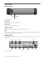
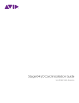
XMON Interface
XMON Front Panel
Power
switch
Mute
indicator
MIDI Receive
indicator
Mute switch
Figure 1. XMON front panel
Power Switch
The Power switch applies power to the XMON Interface.
Mute Indicator
The Mute indicator shows the mute status of XMON.
MIDI Receive Indicator
The MIDI Receive indicator shows MIDI activity between XMON and the control surface.
Mute
The Mute switch mutes all XMON outputs. It is not possible to unmute XMON with this switch. The XMON mute state can only
be cleared from the Monitor section of your control surface.
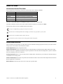
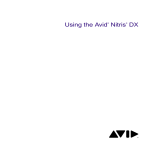
XMON Back Panel
The back panel of the XMON interface includes connectors for all external analog audio inputs and outputs, power, and control
(15-pin D-Sub).
Cue Inputs
Main Inputs
Cue Outputs
Main Outputs
Surround Inputs
Alt Outputs
Stereo Inputs
Talkback/
Listenback/
Utility
Meter Calibration
Screws
Control connector AC Power
Figure 2. XMON back panel
Chapter 1: Introduction to the XMON EUCON Software Application
3
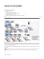
Chapter 2: Installing XMON
This chapter includes the following:
• Making audio connections
• Installing the USB-to-MIDI Adapter
• Connecting the Control Cable Breakout Adapter
• Connecting a Talkback microphone
• Installing and configuring the XMON EUCON Software Application
Making Audio Connections
Figure 3. XMON audio connections
Monitoring is based on the XMON analog interface, which is remotely controlled from the XMON EUCON Software Application
and the S6 Control Room section. All supported audio inputs and outputs for control room monitoring and studio communication
are connected to the XMON interface.
All audio connections are made with standard DB-25 connectors. See Appendix A, “DB-25 Connectors” for wiring convention and
pinout tables.
XMON provides 18V phantom power for the Talkback 2 Mic that connects via the DB-25 connector. The Talkback 1 mic, which
is carried on the 15-pin Control Cable, requires an external mic preamp (not included) with phantom power supply.
Chapter 2: Installing XMON
4
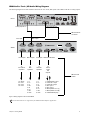
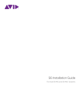
XMON-to-Pro Tools | HD Audio Wiring Diagram
The following diagram shows basic XMON connections for a Pro Tools | HD system with an HD I/O that has 16 analog outputs.
HD I/O
Analog Outputs 1-8
Analog Outputs 9-16
DB-25 to DB-25
connectors
Cue Inputs
Main Inputs
XMON
Cue Outputs
To
Cue System
Amplifiers
Main Outputs
To
Main
Speakers
Alt Outputs Talkback/Listenback
To
Alternate
Speakers
To
Various
Inputs
and
Outputs
DB-25 to XLR
snakes
1-2: Studio
3-4: Cue 1
5-6: Cue 2
7-8: Cue 3
1=L
2 = Lc
3=C
4 = Rc
5=R
6 = Ls
7 = Rs
8 = LFE
1=L
2 = Lc
3=C
4 = Rc
5=R
6 = Ls
7 = Rs
8 = LFE
1 = Talkback Mic 2 Input
2 = Listen Mic 1 Input
3 = Listen Mic 2 Input
4 = AFL Input 1
5 = AFL Input 2
6 = Mini Speaker Out 1 (L)
7 = Mini Speaker Out 2 (R)
8 = Talkback/Slate (Out)
Figure 4. Wiring diagram for HD I/O and XMON
Not all channels shown are supported by the XMON EUCON Software Application.
Chapter 2: Installing XMON
5
Installing the USB-to-MIDI Adapter
The included USB-to-MIDI adapter allows supported control surfaces to communicate with the workstation on which the XMON
EUCON software is installed.
To install the USB-to-MIDI adapter:
1
Connect the USB end to a USB port on the workstation on which you will be installing XMON EUCON software.
2
Leave the MIDI IN and OUT jacks unconnected for now (these will be connected after installing the breakout cable.
Network Connections
The workstation on which you will be installing XMON EUCON Software must be connected to the control surface network. If you
are installing XMON EUCON on the same workstation as one of your DAWs or other EUCON-aware applications, the required
Ethernet connection between devices is already in place. If you will be installing XMON EUCON on a dedicated (non-DAW)
workstation, you must connect that workstation to your control surface network.
For example, with S6 you must connect the workstation to the S6 Ethernet switch. After connecting the Control Cable Breakout
Adapter, install WSControl and XMON EUCON Software on the workstation (explained later in this guide). Make sure the workstation is recognized and connected to S6 in the Settings > Workstation screen.
Connecting the Control Cable Breakout Adapter
The Control Cable Breakout Adapter lets the XMON EUCON Software Application communicate with and control the XMON
hardware. It also provides an audio connection for the XMON Talkback 1 and a Headphone jack.
Figure 5. Control Cable Breakout Adapter
To connect the Control Cable Breakout Adapter:
1
Connect the 15-pin end of the Control Cable Breakout Adapter to the Control port on the back panel of the XMON hardware.
2
Connect the MIDI OUT cable from the USB-to-MIDI adapter to the MIDI IN port on the Control Cable Breakout Adapter.
3
Connect the MIDI IN cable from the USB-to-MIDI adapter to the MIDI OUT port on the Control Cable Breakout Adapter.
Headphones
To connect headphones:
Use a 1/4-inch TRS cable (not included) to connect the Headphone Out on the Control Cable Breakout Adapter to a headphone
amp, or connect headphones directly.
Connecting a Talkback Microphone
The XMON EUCON Software Application supports both of the Talkback channels (1 and 2) available on XMON.
Talkback 1 Connects as part of the 15-pin Control Cable. Does not provide phantom power. Talkback 1 requires a mic preamp be-
tween the S6 and XMON. If using a condenser mic, the mic pre needs to provide phantom power.
Talkback 2 Connects via DB-25 cable to the XMON TB/LB/UTIL port. Talkback 2 provides +18V phantom power.
Chapter 2: Installing XMON
6
Use the following instructions to connect Talkback as appropriate for your talkback mic requirements.
To connect a Talkback microphone:
1
Connect an XLR cable to the Talkback Thru port on the back of the Master Module (a 90o connector is recommended).
2
Do one of the following, depending on the type of microphone you want to use for talkback:
48V To use a microphone that requires 48V phantom power, connect the other end of the cable to the input of a mic preamp with
phantom power (not included). For 48V, you must use an external mic preamp with phantom power. Connect the output of the mic
preamp to the Talkback input (Talkback 1) on the Control Cable Breakout Adapter.
18V To use a microphone that requires 18V (such as a low-power condenser), connect the other end of the XLR cable to the Talkback 2 Microphone input on the back panel of the XMON hardware (on the TB/LB/UTIL DB-25 connector).
Installing and Configuring the XMON EUCON Software Application
XMON EUCON is included with S6 Workstation software. Download the WS installer from your Avid Master Account and launch
it.
• On Mac, XMON is automatically installed along with WSControl.
• On Windows, the installer lets you choose to install XMON EUCON or Studio Monitor Pro (SMP 2). Select XMON EUCON.
Follow the on-screen instructions to complete installation.
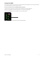
Selecting a MIDI Port
The XMON EUCON Software Application uses a MIDI port to communicate with the XMON hardware. The Mac and Windows
versions of XMON select this port differently.
Pro Tools users must deselect the MIDI device that XMON uses in Setup>MIDI>Input Devices.
Mac
Right-click the XMON icon in the dock and select a MIDI port from the Select MIDI port menu. If you are using the included MIDI
device, select it. Otherwise, select another MIDI port.
Windows
In Windows, click the XMON icon in the task tray and select a MIDI port from the Select MIDI port menu. If you are using the included MIDI device, select it. Otherwise, select another MIDI port.
XMON icon
XMON icon
Figure 6. Mac (left) and Windows (right) MIDI Port selection
Chapter 2: Installing XMON
7
Locking S6 to XMON
The Control Room and Monitor section of S6 must be locked to the XMON software application to retain control of the studio levels while other applications or another workstation is in focus.
To lock the Control Room section to the XMON EUCON Software Application:
1
Make sure the S6 is attached to the workstation running the XMON EUCON Software Application.
2
Make sure the XMON EUCON Software Application is in focus (the front-most application).
3
Press the upper Setup button in the Control Room section of the Master Module.
Mon A
0.00
CR L/R In
Mon B
Coms
Setup
Talk
Setup
Figure 7. Setup (Lock) switch in the Control Room section of the S6 Master Module
Chapter 2: Installing XMON
8
Chapter 3: Using XMON
This chapter explains how to use XMON with S6 and includes the following sections.
• “XMON to EUCON Mapping” on page 9 (all systems)
• “Using XMON with S6” on page 10
XMON to EUCON Mapping
This section clarifies the terminology used for the XMON and S6.
Control Room
The Control Room section on S6, MC Pro and System 5-MC can route input sources to three sets of outputs.
Main Spkrs Routes selected source(s) to the Main 1–8 (7.1-channel) outputs on the XMON hardware.
Alt 1 Spkrs Routes selected source(s) to the Alt 1–8 (7.1-channel) outputs on the XMON hardware.
Alt 2 Spkrs Feeds selected source(s) to the Mini 1–2 (stereo) outputs on the XMON hardware, on the TB/LB/UTIL connector
(XLR-M 6–7).
Monitors A–E
The Monitor section can control the following levels, as available on your system.
Mon A Controls the output level of the Headphone Output on the XMON Control Cable Breakout Adapter.
Mon B Controls the output level of the XMON CUE OUTPUT 1-2 (StLS L/R).
Mon C Controls the output level of the XMON CUE OUTPUT 3-4 (Cue 1 L/R).
Mon D Controls the output level of the XMON CUE OUTPUT 5-6 (Cue 2 L/R).
Mon E Controls the output level of the XMON CUE OUTPUT 7-8 (Cue 3 L/R).
Monitor D and E
To focus Monitor E controls from S6:
1
Open XMON EUCON Software and click to show the Main tab.
2
Click the box next to Control from surface to toggle it between MonD (the default setting) and MonE. On the Master Module
Touchscreen, Monitoring page, the lower left knob follows the selection.
Figure 8. Main tab in XMON EUCON Software
Chapter 3: Using XMON
9
Using XMON with S6
This section explains the following monitoring features when using XMON with S6.
• “Selecting Sources” on page 10
• “Setting Control Room, Monitor, and Dim Levels” on page 12
• “Speaker Management” on page 13
Selecting Sources
S6 lets you assign XMON input sources to the Control Room and Monitor outputs.
To select input sources for the Control Room:
1
Press the lower Setup switch in the Control Room section to display the Monitoring screen.
0.00
Mon A
CR L/R In
Mon B
Coms
Setup
Talk
Setup
Figure 9. Setup (Monitoring screen) switch in the Control Room section of the S6 Master Module
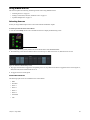
2
The Monitoring screen shows available sources across the top row. Blue sources are on; dimmed sources are off.
Figure 10. Sources in the Monitoring screen
3
Tap a gray Source button to toggle the corresponding source on; tap a blue source button to toggle that Source off. In Figure 10,
Main, Surround, and Listenback sources are on.
4
To toggle all sources on/off, tap All.
Control Room Sources
The following input sources are available for the Control Room:
• Main
• Surround
• Stereo 1
• Stereo 2
• Stereo 3
• Stereo 4
• Listenback
• AFL
Chapter 3: Using XMON
10
You can re-order Sources in the upper row so that they appear in different Source boxes.
To re-order sources in the Source row:
1
Tap the Source name shown in the upper row. A yellow outline surrounds the name, and the Source Select list appears in the center of the Touchscreen with the current assignment highlighted.
Figure 11. Selecting a Source to re-order
2
Tap in the Source Select list to select a different Source to occupy the currently selected Source box.
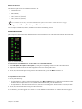
Monitors A–D
To select input sources for the four Monitor feeds:
1
Navigate the Touchscreen to the Monitoring screen.
2
Select a Monitor bus to configure by tapping its green box (A, B, C, or D). The center of the Touchscreen displays the Monitor
Select list for the current Monitor feed
3
Touch a source in the list to activate it for the currently selected Monitor feed.
Active sources are lit blue, inactive sources are gray. In Figure 12, CR L/R In and Talk are active for Monitor A.
Figure 12. Choosing Monitor A sources on S6
Chapter 3: Using XMON
11
Monitor A–D Sources
The following input sources are available for Monitor A–D:
• Control Room L/R
• Talk (Talkback)
• Cue 1 (Monitor A, B, and C)
• Cue 2 (Monitor A, B, and D)
• Cue 3 (Monitor A, B, and E)
Access to Monitor E can only be selected in XMON EUCON software as described in “Monitor D and E” on page 9.
Setting Control Room, Monitor, and Dim Levels
You can adjust Control Room, Monitor, and Dim levels from the S6 Monitoring section.
Control Room Levels
The Control Room knob in the Master Module Monitoring section adjusts the level of the three Control Room output feeds independently.
0.00
Mon A
CR L/R In
Mon B
Coms
Setup
Talk
Setup
Mon
Insert
Alt 1
Spkrs
Alt 2
Spkrs
Main
Spkrs
Setup
Dim
Cut
Figure 13. Control Room knob
To adjust the level of the Main Spkrs (7.1), Alt 1 Spkrs (7.1), or Alt 2 Spkrs (Stereo):
1
Select Main Spkrs, Alt 1 Spkrs, or Alt 2 Spkrs by pressing the corresponding switch next to the Control Room knob.
2
Adjust the Control Room knob to the desired playback level for the selected speaker feed.
3
To cut (mute) the selected Speaker feed, press the Control Room knob, or press the Mute switch below it.
Monitor Levels
To adjust Monitor levels from S6:
1
Do any of the following:
• To adjust Monitor A or B levels using the Monitor knob, press Mon A or Mon B next to the Monitor level knob, then rotate
the Monitor knob to adjust the level. to cut (mute) the selected Monitor feed, press the Monitor knob.
• To adjust Monitor A–D from the Touchscreen knobs, rotate the corresponding knob. Press the knob to cut (mute) the feed.
2
To cut (mute) the selected Monitor feed, press the Monitor knob.
3
For Monitor E, you must toggle the “D” control to “E” in the XMON EUCON Software. See “Monitor D and E” on page 9.
Chapter 3: Using XMON
12
Dim Level
Dim can be engaged from S6, and Dim level can be set directly from the S6 Touchscreen.
To engage Dim:
Press the Dim switch below the Control Room knob.
To set the Dim level:
Adjust the Touchscreen knob assigned to Dim, or adjust the Dim level in the Misc tab of XMON EUCON Software.
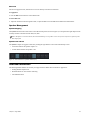
Speaker Management
Speaker Mapping
The Speakers buttons at the bottom of the Control Room Setup screen (shown in Figure 14) correspond to the eight outputs for the
currently selected Control Room feed: Main, Alt, Mini.
When Alt 2 Spkrs is selected on the S6, the Control Room Setup screen speaker selector array shows only the two speakers for the
Mini output feed.
Speakers On and Off
The Speakers outputs are toggled on and off by clicking the eight buttons on the Control Room Setup screen.
• A lit button indicates the speaker output is on.
• An unlit button indicates the speaker is off.
Figure 14. Two Control Room speakers enabled (on)
Additional Information
The following XMON features are currently not supported in the XMON EUCON Software Application:
• Linking Monitor Output levels
• Broadcast Mode for AFL and PFL monitoring
• Auto Talkback Mode
Chapter 3: Using XMON
13
Appendix A: DB-25 Connectors
This section shows a wiring diagram for each of XMON’s eight DB-25 connectors, and their pinout tables.
All audio connections are made to the back panel of the XMON interface, shown below. All audio connectors are standard female
DB-25 connectors. The connector for communication with S6 is a 15-pin female connector.
Cue Inputs
Main Inputs
Cue Outputs
Main Outputs
Surround Inputs
Alt Outputs
Stereo Inputs
Talkback/Listenback/Utility
Control connector
XMON back panel connectors
25-Pin Female Connector Pinouts
All XMON DB-25 connector pinouts conform to the pin numbering scheme shown below.
13
1
25
DB-25 Connector (user view)
14
Cue Inputs
Cue Inputs
Signal Name
Hot
(+)
Cold
(–)
Ground (shield)
Cue Input 1
24
12
25
Cue Input 2
10
23
11
Cue Input 3
21
9
22
Cue Input 4
7
20
8
Cue Input 5
18
6
19
Cue Input 6
4
17
5
[Not Connected]
15
3
16
[Not Connected]
1
14
2
GND
13
SHIELD GND
connector housing
Appendix A: DB-25 Connectors
14
Main Inputs
Main Inputs
Signal Name
Hot
(+)
Cold
(–)
Ground (shield)
Main Input 1 (L)
24
12
25
Main Input 2 (Lc)
10
23
11
Main Input 3 (C)
21
9
22
Main Input 4 (Rc)
7
20
8
Main Input 5 (R)
18
6
19
Main Input 6 (Ls)
4
17
5
Main Input 7 (Rs)
15
3
16
Main Input 8 (LFE)
1
14
2
GND
13
SHIELD GND
connector housing
Surround Inputs
Surround Inputs
Signal Name
Hot
(+)
Cold
(–)
Ground (shield)
Surround Input 1 (L)
24
12
25
Surround Input 2 (Lc)
10
23
11
Surround Input 3 (C)
21
9
22
Surround Input 4 (Rc)
7
20
8
Surround Input 5 (R)
18
6
19
Surround Input 6 (Ls)
4
17
5
Surround Input 7 (Rs)
15
3
16
Surround Input 8 (LFE)
1
14
2
GND
13
SHIELD GND
connector housing
Appendix A: DB-25 Connectors
15
Stereo Inputs
Stereo Inputs
Signal Name
Hot
(+)
Cold
(–)
Ground (shield)
Stereo Input 1 (Left)
24
12
25
Stereo Input 1 (Right)
10
23
11
Stereo Input 2 (Left)
21
9
22
Stereo Input 2 (Right)
7
20
8
Stereo Input 3 (Left)
18
6
19
Stereo Input 3 (Right)
4
17
5
Stereo Input 4 (Left)
15
3
16
Stereo Input 4 (Right)
1
14
2
GND
13
SHIELD GND
connector housing
Cue Outputs
Cue Outputs
Signal Name
Hot
(+)
Cold
(–)
Ground (shield)
SLS Output (Left)
24
12
25
SLS Output (Right)
10
23
11
Cue Output 1 (Left)
21
9
22
Cue Output 1 (Right)
7
20
8
Cue Output 2 (Left)
18
6
19
Cue Output 2 (Right)
4
17
5
Cue Output 3 (Left)
15
3
16
Cue Output 3 (Right)
1
14
2
GND
13
SHIELD GND
connector housing
Appendix A: DB-25 Connectors
16
Main Speaker Outputs
Main Speaker Outputs
Signal Name
Hot
(+)
Cold
(–)
Ground (shield)
Main 1 (L)
24
12
25
Main 2 (Lc)
10
23
11
Main 3 (C)
21
9
22
Main 4 (Rc)
7
20
8
Main 5 (R)
18
6
19
Main 6 (Ls)
4
17
5
Main 7 (Rs)
15
3
16
Main 8 (LFE)
1
14
2
GND
13
SHIELD GND
connector housing
Alt Speaker Outputs
Alt Speaker Outputs
Signal Name
Hot
(+)
Cold
(–)
Ground (shield)
Alt 1 (L)
24
12
25
Alt 2 (Lc)
10
23
11
Alt 3 (C)
21
9
22
Alt 4 (Rc)
7
20
8
Alt 5 (R)
18
6
19
Alt 6 (Ls)
4
17
5
Alt 7 (Rs)
15
3
16
Alt 8 (LFE)
1
14
2
GND
13
SHIELD GND
connector housing
Appendix A: DB-25 Connectors
17
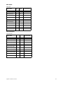
Talkback/Listenback Pinouts
Talkback/Listenback
Signal Name
Hot
(+)
Cold
(–)
Ground (shield)
Talkback 2 Mic Input
24
12
25
Listen Mic 1 Input
10
23
11
Listen Mic 2 Input
21
9
22
AFL Input 1
20
7
8
AFL Input 2
6
18
19
Mini Speaker Out (L)
4
17
5
Mini Speaker Out
(R)
15
3
16
Talkback/Slate Out
1
14
2
GND
13
SHIELD GND
connector housing
15-Pin Connector Pinouts
The XMON 15-pin connector pinouts conform to the pin numbering scheme shown below.
8
1
15
9
15-pin connector (user view)
XMON Control Cable Breakout Adapter Connector Pinouts
XMON Control Cable Breakout Adapter Pinouts
Signal Name
Hot
(+)
Cold
(–)
[Not Connected]
1
9
[Not Connected]
2
10
MIDI Input
12
4
MIDI Output
11
3
Headphones L
13
5
Headphones R
14
6
Talkback 1 Mic
15
8
Ground (shield)
GND
7
SHIELD GND
connector housing
Appendix A: DB-25 Connectors
18
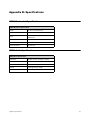
Appendix B: Specifications
XMON Mechanical Specifications
XMON Mechanical Specifications
Height
2U rack, 3.5 inches (8.89 cm)
Width
19 inches (48.26 cm)
Depth
14 inches (35.56 cm), plus 3 inches (7.62 cm) for
cable access
Power
100–240 VAC, 50–60 Hz, 0.5 A
Power Connector
IEC, 3-pin North American standard
Control Connector
15-pin D-Sub
XMON Audio Specifications
XMON Audio Specifications
Gain Range
-90 dB to +30 dB, 1 dB steps, 0.5 dB trim
Frequency Response
20 Hz – 200 kHz, +/-0.1 dB
Maximum Input Level
+26 dB
THD+N
0.0006 @ 1 kHz @ +15 dBu
CMRR
>75 dB
Appendix B: Specifications
19
Appendix C: Compliance Information
Environmental Compliance
Disposal of Waste Equipment by Users in the European Union
This symbol on the product or its packaging indicates that this product must not be disposed of with other waste. Instead, it is your
responsibility to dispose of your waste equipment by handing it over to a designated collection point for the recycling of waste electrical and electronic equipment. The separate collection and recycling of your waste equipment at the time of disposal will help conserve natural resources and ensure that it is recycled in a manner that protects human health and the environment. For more information about where you can drop off your waste equipment for recycling, please contact your local city recycling office or the
dealer from whom you purchased the product.
Proposition 65 Warning
This product contains chemicals, including lead, known to the State of California to cause cancer and birth defects or other reproductive harm. Wash hands after handling.
Perchlorate Notice
This product may contain a lithium coin battery. The State of California requires the following disclosure statement: “Perchlorate
Material – special handling may apply, See www.dtsc.ca.gov/hazardous waste/perchlorate.”
Recycling Notice
Appendix C: Compliance Information
20
EMC (Electromagnetic Compliance)
Avid declares that this product complies with the following standards regulating emissions and immunity:
• FCC Part 15 Class B
• EN55103-1 E4
• EN55103-2 E4
• AS/NZS CISPR 22 Class B
• CISPR 22 Class B
FCC Compliance for United States
Communication Statement
NOTE: This equipment has been tested and found to comply with the limits for a Class B digital device, pursuant to Part 15 of
the FCC Rules. These limits are designed to provide reasonable protection against harmful interference in a residential installation. This equipment generates, uses, and can radiate radio frequency energy and, if not installed and used in accordance with
the instructions, may cause harmful interference to radio communications. However, there is no guarantee that interference will
not occur in a particular installation. If this equipment does cause harmful interference to radio or television reception, which can
be determined by turning the equipment off and on, the user is encouraged to try and correct the interference by one or more of
the following measures:
• Reorient or locate the receiving antenna.
• Increase the separation between the equipment and receiver.
• Connect the equipment into an outlet on a circuit different from that to which the receiver is connected.
• Consult the dealer or an experienced radio/TV technician for help.
Any modifications to the unit, unless expressly approved by Avid, could void the user's authority to operate the equipment.
Australian Compliance
N1709
Canadian Compliance
This Class B digital apparatus meets all requirements of the Canadian Interference-Causing Equipment Regulations.
Cet appareil numérique de la classe B respecte toutes les exigences du Règlement sur le material brouilleur du Canada.
CE Compliance
(EMC and Safety)
Avid is authorized to apply the CE (Conformité Europénne) mark on this compliant equipment thereby declaring conformity to
EMC Directive 2004/108/EC and Low Voltage Directive 2006/95/EC.
Appendix C: Compliance Information
21
Avid
Technical Support (USA)
Product Information
280 N Bernardo Avenue
Mountain View, CA 94043 USA
Visit the Online Support Center at
www.avid.com/support
For company and product information,
visit us on the web at www.avid.com