1
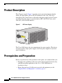
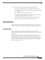
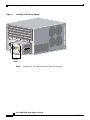
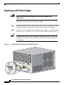
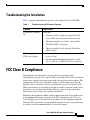
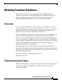
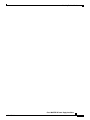
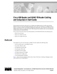
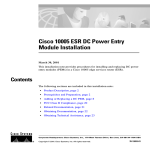
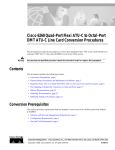
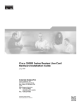
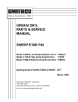
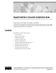
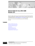
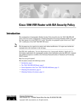
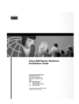
Cisco 10005 ESR AC Power Supply
Installation
March 30, 2001
This installation note provides procedures for installing and replacing AC power
supply modules in a Cisco 10005 edge services router (ESR).
Contents
The following sections are included in this installation note:
•
Product Description, page 2
•
Prerequisites and Preparation, page 2
•
Adding or Replacing an AC Power Supply, page 7
•
FCC Class B Compliance, page 13
•
Related Documentation, page 14
•
Obtaining Documentation, page 15
•
Obtaining Technical Assistance, page 17
Corporate Headquarters: Cisco Systems, Inc., 170 West Tasman Drive, San Jose, CA 95134-1706 USA
Copyright © 2001. Cisco Systems, Inc. All rights reserved.
78-12652-01
Product Description
Product Description
The AC power supply (Figure 1) provides power conversion directly from the
facility AC input power (100 to 240 VAC nominal) to the –48V VDC used
internally by the system. Power is delivered to the power supply by the AC power
cord. The AC power supply is provided with an IEC 320/C20 AC inlet, rated
16A/250V (20A in North America).
Figure 1
AC Power Supply
100-240V
50/60 HZ
15-7A
FAULT
POWER
53616
CAUTION
THIS UNIT
SUPPLY HAS MOR
POWER CORD. DISCE THAN ONE
ONNECT
SUPPLY
POW
SERVICING
COR
TWO (2) ER
TO AVOI DS BEFO
RE
D ELEC
TRIC SHO
CK.
The Cisco 10005 chassis has two compartments for power supplies. The chassis
can operate with a single power supply; install two power supplies if you need
power redundancy.
Prerequisites and Preparation
Before you perform any of the procedures in this guide, we recommend that you:
•
Read the safety guidelines in the next section and review the electrical safety
and ESD-prevention guidelines in the Cisco 10005 ESR Hardware
Installation Guide.
•
Ensure that you have all of the necessary tools and equipment (see the
“Required Tools and Equipment” section on page 6).
Cisco 10005 ESR AC Power Supply Installation
2
78-12652-01
Prerequisites and Preparation
•
Have access to the following documents during the installation:
– Technology of Edge Aggregation: Cisco 10000 Series Edge Services
Router (shipped with your router and available for viewing or download
at Cisco.com)
– Cisco 10005 ESR Hardware Installation Guide
– Cisco 10000 Series ESR Troubleshooting Guide (an online document
available for viewing or download at Cisco.com)
– Cisco 10000 Series ESR Software Configuration Guide (an online
document available for viewing or download at Cisco.com)
Safety Guidelines
Before you begin the installation or replacement procedure, review the safety
guidelines in this section to avoid injuring yourself or damaging the equipment.
Safety Warnings
Safety warnings appear throughout this publication in procedures that, if
performed incorrectly, may harm you. A warning symbol precedes each warning
statement.
Before you install, configure, or perform maintenance on the router, review the
documentation for the procedure you are about to perform, paying special
attention to the safety warnings. If you need translations of the safety warnings,
refer to the “Translated Safety Warnings” appendix of the Cisco 10005 ESR
Hardware Installation Guide.
Cisco 10005 ESR AC Power Supply Installation
78-12652-01
3
Prerequisites and Preparation
Warning
This warning symbol means danger. You are in a situation that could cause
bodily injury. Before you work on any equipment, be aware of the hazards
involved with electrical circuitry and be familiar with standard practices
for preventing accidents. (To see translations of the warnings that appear
in this publication, refer to the appendix “Translated Safety Warnings” in
the installation guide that accompanied this device.)
Waarschuwing
Dit waarschuwingssymbool betekent gevaar. U verkeert in een situatie die
lichamelijk letsel kan veroorzaken. Voordat u aan enige apparatuur gaat
werken, dient u zich bewust te zijn van de bij elektrische schakelingen
betrokken risico’s en dient u op de hoogte te zijn van standaard
maatregelen om ongelukken te voorkomen. (Voor vertalingen van de
waarschuwingen die in deze publicatie verschijnen, kunt u het
aanhangsel “Translated Safety Warnings” (Vertalingen van
veiligheidsvoorschriften) in de installatiegids die bij dit toestel is
ingesloten, raadplegen.
Varoitus
Tämä varoitusmerkki merkitsee vaaraa. Olet tilanteessa, joka voi johtaa
ruumiinvammaan. Ennen kuin työskentelet minkään laitteiston parissa, ota
selvää sähkökytkentöihin liittyvistä vaaroista ja tavanomaisista
onnettomuuksien ehkäisykeinoista. (Tässä julkaisussa esiintyvien
varoitusten käännökset löydät tämän laitteen mukana olevan
asennusoppaan liitteestä "Translated Safety Warnings" (käännetyt
turvallisuutta koskevat varoitukset).)
Attention
Ce symbole d’avertissement indique un danger. Vous vous trouvez dans une
situation pouvant entraîner des blessures. Avant d’accéder à cet
équipement, soyez conscient des dangers posés par les circuits
électriques et familiarisez-vous avec les procédures courantes de
prévention des accidents. Pour obtenir les traductions des mises en garde
figurant dans cette publication, veuillez consulter l’annexe intitulée
« Translated Safety Warnings » (Traduction des avis de sécurité) dans le
guide d’installation qui accompagne cet appareil.
Cisco 10005 ESR AC Power Supply Installation
4
78-12652-01
Prerequisites and Preparation
Warnung
Dieses Warnsymbol bedeutet Gefahr. Sie befinden sich in einer Situation,
die zu einer Körperverletzung führen könnte. Bevor Sie mit der Arbeit an
irgendeinem Gerät beginnen, seien Sie sich der mit elektrischen
Stromkreisen verbundenen Gefahren und der Standardpraktiken zur
Vermeidung von Unfällen bewußt. (Übersetzungen der in dieser
Veröffentlichung enthaltenen Warnhinweise finden Sie im Anhang mit
dem Titel “Translated Safety Warnings” (Übersetzung der Warnhinweise)
in der diesem Gerät beiliegenden Installationsanleitung.)
Avvertenza
Questo simbolo di avvertenza indica un pericolo. Si è in una situazione che
può causare infortuni. Prima di lavorare su qualsiasi apparecchiatura,
occorre conoscere i pericoli relativi ai circuiti elettrici ed essere al
corrente delle pratiche standard per la prevenzione di incidenti. La
traduzione delle avvertenze riportate in questa pubblicazione si trova
nell’appendice, “Translated Safety Warnings” (Traduzione delle
avvertenze di sicurezza), del manuale d’installazione che accompagna
questo dispositivo.
Advarsel
Dette varselsymbolet betyr fare. Du befinner deg i en situasjon som kan
føre til personskade. Før du utfører arbeid på utstyr, må du være
oppmerksom på de faremomentene som elektriske kretser innebærer, samt
gjøre deg kjent med vanlig praksis når det gjelder å unngå ulykker. (Hvis
du vil se oversettelser av de advarslene som finnes i denne publikasjonen,
kan du se i vedlegget "Translated Safety Warnings" [Oversatte
sikkerhetsadvarsler] i installasjonsveiledningen som ble levert med
denne enheten.)
Aviso
Este símbolo de aviso indica perigo. Encontra-se numa situação que lhe
poderá causar danos fisicos. Antes de começar a trabalhar com qualquer
equipamento, familiarize-se com os perigos relacionados com circuitos
eléctricos, e com quaisquer práticas comuns que possam prevenir
possíveis acidentes. (Para ver as traduções dos avisos que constam desta
publicação, consulte o apêndice “Translated Safety Warnings” “Traduções dos Avisos de Segurança”, no guia de instalação que
acompanha este dispositivo).
Cisco 10005 ESR AC Power Supply Installation
78-12652-01
5
Prerequisites and Preparation
¡Advertencia!
Varning!
Este símbolo de aviso significa peligro. Existe riesgo para su integridad
física. Antes de manipular cualquier equipo, considerar los riesgos que
entraña la corriente eléctrica y familiarizarse con los procedimientos
estándar de prevención de accidentes. (Para ver traducciones de las
advertencias que aparecen en esta publicación, consultar el apéndice
titulado “Translated Safety Warnings,” en la guía de instalación que se
acompaña con este dispositivo.)
Denna varningssymbol signalerar fara. Du befinner dig i en situation som
kan leda till personskada. Innan du utför arbete på någon utrustning måste
du vara medveten om farorna med elkretsar och känna till vanligt
förfarande för att förebygga skador. (Se förklaringar av de varningar som
förekommer i denna publikation i appendix "Translated Safety Warnings"
[Översatta säkerhetsvarningar] i den installationshandbok som medföljer
denna anordning.)
Required Tools and Equipment
You need the following tools and equipment to install an AC power supply:
•
Number 2 phillips screwdriver.
•
Electrostatic discharge (ESD) preventive wrist or ankle strap with
connection cord.
•
AC power cord compatible with your power outlets. The Cisco 10005 ESR
Hardware Installation Guide describes AC power cords available for the
Cisco 10005 ESR.
Cisco 10005 ESR AC Power Supply Installation
6
78-12652-01
Adding or Replacing an AC Power Supply
Adding or Replacing an AC Power Supply
This section describes how to add or replace an AC power supply in a Cisco 10005
chassis. It contains these procedures:
•
Installing a Second AC Power Supply
•
Replacing an AC Power Supply
•
Troubleshooting the Installation
Installing a Second AC Power Supply
Warning
Never install an AC power module and a DC power module in the same
chassis.
Follow these steps to install a second AC power supply for redundancy:
Step 1
Put on an antistatic wrist or ankle strap. Attach the strap to the ESD grounding
jack on the front of the chassis or to a bare metal surface of the chassis.
Step 2
At the rear of the chassis, loosen the captive screws to remove the blank cover
from the empty power compartment.
Step 3
Before you install the new power supply, push on the left side of the power switch
to set the power supply to standby mode.
Step 4
Insert the new AC power supply all the way into the power bay to ensure a secure
connection to the midplane (Figure 2). Tighten the captive screws.
Cisco 10005 ESR AC Power Supply Installation
78-12652-01
7
Adding or Replacing an AC Power Supply
Figure 2
RX
RX
RX
RX
RX
TX
TX
TX
TX
TX
Installing an AC Power Supply
RX
TX
RX
TX
RX
TX
RX
TX
RX
TX
TX
RX
TX
RX
RX
TX
RX
RX
TX
RX
RX
TX
RX
TX
RX
TX
RX
TX
RX
TX
RX
TX
RX
TX
TX
TX
TX
TX
RX
RX
RX
RX
RX
MINOR
ALARM
TX
TX
TX
TX
TX
RX
RX
RX
RX
RX
MAJOR
ALARM
EXT
CLOCK
A+
AB+
B-
NO
CO
NC
NO
CO
NC
NO
CO
NC
CRITICAL
ALARM
RX
RX
TX
TX
TX
TX
TX
RX
RX
RX
RX
RX
TX
TX
TX
TX
TX
60 VDC
1A MAX
100-240V
50/60 HZ
15-7A
CAUTIO
THIS UNIT
N
SUPPLY HAS MORE
THAN
POWER CORD. DISCON
ONE
SERVIC SUPPLY CORDSNECT TWOPOWER
ING TO
BEFOR (2)
AVOID
ELECTR E
IC SHOCK
.
53836
100-240V
50/60 HZ
15-7A
FAULT
POWER
FAULT
POWER
CAUTIO
THIS UNIT
N
SUPPLY HAS MORE
THAN
POWER CORD. DISCON
ONE
SERVIC SUPPLY CORDSNECT TWOPOWER
ING TO
BEFOR (2)
AVOID
ELECTR E
IC SHOCK
.
Captive
screws
Step 5
Connect the AC power cord to the new power supply.
Cisco 10005 ESR AC Power Supply Installation
8
78-12652-01
Adding or Replacing an AC Power Supply
Step 6
Snug up the strain relief device that secures the power cord to the power supply.
To do this, tighten the screw underneath the connector (Figure 3).
Figure 3
Tightening AC Power Cord Strain Relief
0V
2424
0V
0-01010
ZZ
0 0HH
/6/6
5050
AA
-7-7
1515
ION
RR
WE
UTION
PO
WE
CAUT
CA
EEPO
ON
ANON
(2)
THAN
C
AC
OO(2)
RETH
UA
TW
NNOOIITTU
MORE
ECTTTW
S MO
NNEC
HAS
RE
CONN
RE
FO
DISCO
K.K.
UNIT HA
BEFO
OC
IS UN
OC
RD.. DIS
TH
SH
THIS
RDSSBE
CORD
ICSH
IC
CORD
TR
LY CO
ECTR
PPLY SUPP
PPLY
SU
ELEC
SUPP
EL
OID
R
OID
AV
WE
TO AV
TO
PO
POWE
RVICING
SERV
Step 7
53630
POWER
Warning
FAULT
FAULT
SE
Do not over-tighten the strain relief devices that secure the power cords to
the power supplies. Because this chassis cannot be switched off
completely, you must disconnect the power cords to remove power from the
chassis. The power cord serves as the primary disconnect in an emergency.
Plug the power cord into a power receptacle.
When you connect power to the power supply while it is in standby mode, the
yellow Fault LED lights.
Step 8
Set the power switch on the new power supply to the | (On) position.
The green Power LED on the power supply lights, indicating that the power
supply is supplying power to the chassis. The yellow Fault LED goes out.
Cisco 10005 ESR AC Power Supply Installation
78-12652-01
9
Adding or Replacing an AC Power Supply
Replacing an AC Power Supply
Never install an AC power module and a DC power module in the
same chassis.
Warning
Follow these steps to replace an AC power supply:
Step 1
Put on an antistatic wrist or ankle strap. Attach the strap to the ESD grounding
jack on the front of the chassis or to the bare metal surface of the chassis.
Step 2
If your system is configured with redundant power supplies, set only the power
switch of the power supply you are replacing to the standby position (Figure 4).
Do not power off both AC power supplies in a redundant system, or the system
shuts down and all data traffic stops. Power off only the AC power supply you
are replacing.
Caution
Figure 4
Setting AC Power Switch to the Standby Position
RX
RX
RX
RX
RX
TX
TX
TX
TX
TX
RX
TX
RX
TX
RX
TX
RX
TX
RX
TX
TX
RX
RX
TX
RX
RX
TX
RX
RX
TX
RX
RX
TX
RX
TX
TX
TX
TX
TX
RX
RX
RX
RX
RX
TX
RX
TX
RX
TX
RX
TX
RX
TX
RX
MINOR
ALARM
TX
TX
TX
TX
TX
RX
RX
RX
RX
RX
TX
RX
TX
RX
TX
RX
TX
RX
TX
RX
MAJOR
ALARM
EXT
CLOCK
A+
AB+
B-
NO
CO
NC
NO
CO
NC
NO
CO
NC
CRITICAL
ALARM
RX
TX
TX
TX
TX
TX
60 VDC
1A MAX
100-240V
50/60 HZ
15-7A
CAUTIO
THIS UNIT
N
SUPPLY HAS MORE
THAN
POWER CORD. DISCON
ONE
SERVIC SUPPLY CORDSNECT TWOPOWER
ING TO
BEFOR (2)
AVOID
ELECTR E
IC SHOCK
.
53629
100-240V
50/60 HZ
15-7A
FAULT
FAULT
POWER
FAULT
POWER
POWER
CAUTIO
THIS UNIT
N
SUPPLY HAS MORE
THAN
POWER CORD. DISCON
ONE
SERVIC SUPPLY CORDSNECT TWOPOWER
ING TO
BEFOR (2)
AVOID
ELECTR E
IC SHOCK
.
Cisco 10005 ESR AC Power Supply Installation
10
78-12652-01
Adding or Replacing an AC Power Supply
Figure 5
RX
RX
RX
RX
RX
TX
TX
TX
TX
TX
Step 3
Disconnect the power cable from the power supply that you are replacing.
Step 4
Loosen the captive screws on the power supply and pull the power supply from
the chassis using the handle on the faceplate.
Step 5
Before you install the new power supply, make sure that its power switch is set to
the standby position (see Figure 4).
Step 6
Insert the new AC power supply all the way into the power bay to ensure a secure
connection to the midplane (Figure 5). Tighten the captive screws on the power
supply.
Installing an AC Power Supply
RX
TX
RX
TX
RX
TX
RX
TX
RX
TX
TX
RX
TX
RX
RX
TX
RX
RX
TX
RX
RX
TX
RX
TX
RX
TX
RX
TX
RX
TX
RX
TX
RX
TX
TX
TX
TX
TX
RX
RX
RX
RX
RX
MINOR
ALARM
TX
TX
TX
TX
TX
RX
RX
RX
RX
RX
MAJOR
ALARM
EXT
CLOCK
A+
AB+
B-
NO
CO
NC
NO
CO
NC
NO
CO
NC
CRITICAL
ALARM
RX
RX
TX
TX
TX
TX
TX
RX
RX
RX
RX
RX
TX
TX
TX
TX
TX
60 VDC
1A MAX
100-240V
50/60 HZ
15-7A
CAUTIO
THIS UNIT
N
SUPPLY HAS MORE
THAN
POWER CORD. DISCON
ONE
SERVIC SUPPLY CORDSNECT TWOPOWER
ING TO
BEFOR (2)
AVOID
ELECTR E
IC SHOCK
.
53836
100-240V
50/60 HZ
15-7A
FAULT
POWER
FAULT
POWER
CAUTIO
THIS UNIT
N
SUPPLY HAS MORE
THAN
POWER CORD. DISCON
ONE
SERVIC SUPPLY CORDSNECT TWOPOWER
ING TO
BEFOR (2)
AVOID
ELECTR E
IC SHOCK
.
Captive
screws
Step 7
Connect the power cord to the new power supply.
Cisco 10005 ESR AC Power Supply Installation
78-12652-01
11
Adding or Replacing an AC Power Supply
Snug up the strain relief device that secures the power cord to the power supply.
To do this, tighten the screw underneath the connector (Figure 6).
Tightening AC Power Cord Strain Relief
ION
RR
WE
UTION
PO
WE
CAUT
CA
EEPO
ON
ANON
(2)
THAN
C
AC
OO(2)
RETH
UA
TW
NNOOIITTU
MORE
ECTTTW
S MO
NNEC
HAS
RE
CONN
RE
FO
DISCO
K.K.
UNIT HA
BEFO
OC
IS UN
OC
RD.. DIS
TH
SH
THIS
RDSSBE
CORD
ICSH
IC
CORD
TR
LY CO
ECTR
PPLY SUPP
PPLY
SU
ELEC
SUPP
OIDEL
R
OID
AV
AV
WE
WE
TO
TO
PO
PO
RVICING
SERV
SE
POWER
0V
2424
0V
0-01010
ZZ
0 0HH
/6/6
5050
AA
-7-7
1515
Warning
Step 9
53630
Figure 6
FAULT
FAULT
Step 8
Do not over-tighten the strain relief devices that secure the power cords to
the power supplies. Because this chassis cannot be switched off
completely, you must disconnect the power cords to remove power from the
chassis. The power cord serves as the primary disconnect in an emergency.
Plug the power cord into a power receptacle.
When you connect power to the power supply while it is in standby mode, the
yellow Fault LED lights up.
Step 10
Set the power switch on the new power supply to the | (On) position.
The green Power LED on the power supply lights up, indicating that the power
supply is supplying power to the chassis. The yellow Fault LED goes out.
Cisco 10005 ESR AC Power Supply Installation
12
78-12652-01
FCC Class B Compliance
Troubleshooting the Installation
Table 1 contains troubleshooting tips for an AC-powered Cisco 10005 ESR.
Table 1
Troubleshooting AC-Powered Systems
Symptom
Steps to Take
System fails to power
on
Check that:
Power supply Fault
LED is on (yellow)
•
All power cords are properly connected to the
Cisco 10005 and at the power connection end.
•
The power switches are in the | (On) position.
•
The Power LED is on (green).
•
The fan assembly is fully inserted (Fan Status
LED is green).
•
Make sure the power switch on the power module
is set to | (On).
•
For more troubleshooting information, see the
Cisco 10000 Series ESR Troubleshooting Guide.
FCC Class B Compliance
The equipment described in this manual generates and might radiate
radio-frequency energy. If it is not installed in accordance with Cisco installation
instructions, it might cause interference with radio and television reception. This
equipment has been tested and found to comply with the limits for a Class B
digital device in accordance with the specifications in part 15 of the FCC rules.
These specifications are designed to provide reasonable protection against such
interference in a residential installation. However, there is no guarantee that
interference will not occur in a particular installation.
Modifying the equipment without written authorization from Cisco might result
in the equipment no longer complying with FCC requirements for Class A or
Class B digital devices. In that event, your right to use the equipment might be
limited by FCC regulations, and you might be required to correct any interference
to radio or television communications at your own expense.
Cisco 10005 ESR AC Power Supply Installation
78-12652-01
13
Related Documentation
You can determine whether your equipment is causing interference by turning it
off. If the interference stops, it was probably caused by the Cisco equipment or
one of its peripheral devices. If the equipment causes interference to radio or
television reception, try to correct the interference by using one or more of the
following measures:
•
Turn the television or radio antenna until the interference stops.
•
Move the equipment to one side or the other of the television or radio.
•
Move the equipment farther away from the television or radio.
•
Plug the equipment into an outlet that is on a different circuit from the
television or radio. (That is, make certain the equipment and the television or
radio are on circuits controlled by different circuit breakers or fuses.)
Modifications to this product not authorized by Cisco Systems, Inc. could void the
FCC approval and negate your authority to operate the product.
Related Documentation
This section lists the manuals in the Cisco 10000 series documentation set.
Manuals for All Cisco 10000 Series Routers
•
Technology of Edge Aggregation: Cisco 10000 Series Edge Services Router
•
Cisco 10000 Series ESR Performance Routing Engine Installation
•
Cisco 10000 Series ESR OC-12 Packet Over SONET Line Card Installation
•
Cisco 10000 Series ESR OC-12 ATM Line Card Installation
•
Cisco 10000 Series ESR Single-Port Gigabit Ethernet Line Card Installation
•
Cisco 10000 Series ESR Channelized OC-12 Line Card Installation
•
Cisco 10000 Series ESR 6-Port Channelized T3 Line Card Installation
•
Cisco 10000 Series ESR Channelized STM-1 Line Card Installation
•
Release notes for the Cisco 10000 series ESR
These documents, which are available at Cisco.com, are online only:
•
Cisco 10000 Series ESR Software Configuration Guide
•
Cisco 10000 Series ESR Troubleshooting Guide
Cisco 10005 ESR AC Power Supply Installation
14
78-12652-01
Obtaining Documentation
•
Cisco 10000 Series ESR Useful Links
•
Cisco 10000 technical reference documents
Hardware Documents for Cisco 10008 Routers
•
Cisco 10008 ESR Hardware Installation Guide
•
Cisco 10008 ESR AC Power Entry Module Installation
•
Cisco 10008 ESR DC Power Entry Module Installation
•
Cisco 10008 ESR Blower Module Installation
Hardware Documents for Cisco 10005 Routers
•
Cisco 10005 ESR Hardware Installation Guide
•
Cisco 10005 ESR Hardware Overview and Maintenance Guide (online only)
•
Cisco 10005 ESR AC Power Supply Installation
•
Cisco 10005 ESR DC Power Entry Module Installation
•
Cisco 10005 ESR Fan Assembly Installation
Obtaining Documentation
The sections that follow provide sources for obtaining documentation from
Cisco Systems.
World Wide Web
You can access the most current Cisco documentation on the World Wide Web at
the following sites:
•
http://www.cisco.com
•
http://www-china.cisco.com
•
http://www-europe.cisco.com
Cisco 10005 ESR AC Power Supply Installation
78-12652-01
15
Obtaining Documentation
Documentation CD-ROM
Cisco documentation and additional literature are available in a CD-ROM
package, which ships with your product. The Documentation CD-ROM is updated
monthly and may be more current than printed documentation. The CD-ROM
package is available as a single unit or through an annual subscription.
Ordering Documentation
Cisco documentation is available in the following ways:
•
Registered Cisco Direct Customers can order Cisco Product documentation
from the Networking Products MarketPlace:
http://www.cisco.com/cgi-bin/order/order_root.pl
•
Registered Cisco.com users can order the Documentation CD-ROM through
the online Subscription Store:
http://www.cisco.com/go/subscription
•
Nonregistered Cisco.com users can order documentation through a local
account representative by calling Cisco corporate headquarters (California,
USA) at 408 526-7208 or, in North America, by calling
800 553-NETS (6387).
Documentation Feedback
If you are reading Cisco product documentation on the World Wide Web, you can
submit technical comments electronically. Click Feedback in the toolbar and
select Documentation. After you complete the form, click Submit to send it to
Cisco.
You can e-mail your comments to bug-doc@cisco.com.
To submit your comments by mail, use the response card behind the front cover
of your document, or write to the following address:
Attn Document Resource Connection
Cisco Systems, Inc.
170 West Tasman Drive
San Jose, CA 95134-9883
Cisco 10005 ESR AC Power Supply Installation
16
78-12652-01
Obtaining Technical Assistance
Obtaining Technical Assistance
Cisco provides Cisco.com as a starting point for all technical assistance.
Customers and partners can obtain documentation, troubleshooting tips, and
sample configurations from online tools. For Cisco.com registered users,
additional troubleshooting tools are available from the TAC website.
Cisco.com
Cisco.com is the foundation of a suite of interactive, networked services that
provides immediate, open access to Cisco information and resources at anytime,
from anywhere in the world. This highly integrated Internet application is a
powerful, easy-to-use tool for doing business with Cisco.
Cisco.com provides a broad range of features and services to help customers and
partners streamline business processes and improve productivity. Through
Cisco.com, you can find information about Cisco and our networking solutions,
services, and programs. In addition, you can resolve technical issues with online
technical support, download and test software packages, and order Cisco learning
materials and merchandise. Valuable online skill assessment, training, and
certification programs are also available.
Customers and partners can self-register on Cisco.com to obtain additional
personalized information and services. Registered users can order products, check
on the status of an order, access technical support, and view benefits specific to
their relationships with Cisco.
To access Cisco.com, go to the following website:
http://www.cisco.com
Technical Assistance Center
The Cisco TAC website is available to all customers who need technical assistance
with a Cisco product or technology that is under warranty or covered by a
maintenance contract.
Cisco 10005 ESR AC Power Supply Installation
78-12652-01
17
Obtaining Technical Assistance
Contacting TAC by Using the Cisco TAC Website
If you have a priority level 3 (P3) or priority level 4 (P4) problem, contact TAC
by going to the TAC website:
http://www.cisco.com/tac
P3 and P4 level problems are defined as follows:
•
P3—Your network performance is degraded. Network functionality is
noticeably impaired, but most business operations continue.
•
P4—You need information or assistance on Cisco product capabilities,
product installation, or basic product configuration.
In each of the above cases, use the Cisco TAC website to quickly find answers to
your questions.
To register for Cisco.com, go to the following website:
http://www.cisco.com/register/
If you cannot resolve your technical issue by using the TAC online resources,
Cisco.com registered users can open a case online by using the TAC Case Open
tool at the following website:
http://www.cisco.com/tac/caseopen
Contacting TAC by Telephone
If you have a priority level 1(P1) or priority level 2 (P2) problem, contact TAC by
telephone and immediately open a case. To obtain a directory of toll-free numbers
for your country, go to the following website:
http://www.cisco.com/warp/public/687/Directory/DirTAC.shtml
P1 and P2 level problems are defined as follows:
•
P1—Your production network is down, causing a critical impact to business
operations if service is not restored quickly. No workaround is available.
•
P2—Your production network is severely degraded, affecting significant
aspects of your business operations. No workaround is available.
Cisco 10005 ESR AC Power Supply Installation
18
78-12652-01
Obtaining Technical Assistance
Cisco 10005 ESR AC Power Supply Installation
78-12652-01
19
Obtaining Technical Assistance
Use this document in conjunction with the documents listed in the “Related Documentation” section.
AccessPath, AtmDirector, Browse with Me, CCDA, CCDE, CCDP, CCIE, CCNA, CCNP, CCSI, CD-PAC,
CiscoLink, the Cisco NetWorks logo, the Cisco Powered Network logo, Cisco Systems Networking Academy, the
Cisco Systems Networking Academy logo, Fast Step, Follow Me Browsing, FormShare, FrameShare, GigaStack,
IGX, Internet Quotient, IP/VC, iQ Breakthrough, iQ Expertise, iQ FastTrack, the iQ Logo, iQ Net Readiness
Scorecard, MGX, the Networkers logo, Packet, PIX, RateMUX, ScriptBuilder, ScriptShare, SlideCast, SMARTnet,
TransPath, Unity, Voice LAN, Wavelength Router, and WebViewer are trademarks of Cisco Systems, Inc.; Changing
the Way We Work, Live, Play, and Learn, Discover All That’s Possible, and Empowering the Internet Generation, are
service marks of Cisco Systems, Inc.; and Aironet, ASIST, BPX, Catalyst, Cisco, the Cisco Certified Internetwork
Expert logo, Cisco IOS, the Cisco IOS logo, Cisco Systems, Cisco Systems Capital, the Cisco Systems logo,
Enterprise/Solver, EtherChannel, EtherSwitch, FastHub, FastSwitch, IOS, IP/TV, LightStream, MICA, Network
Registrar, Post-Routing, Pre-Routing, Registrar, StrataView Plus, Stratm, SwitchProbe, TeleRouter, and VCO are
registered trademarks of Cisco Systems, Inc. or its affiliates in the U.S. and certain other countries.
All other brands, names, or trademarks mentioned in this document or Web site are the property of their respective
owners. The use of the word partner does not imply a partnership relationship between Cisco and any other company.
(0102R)
Copyright © 2001, Cisco Systems, Inc.
All rights reserved.
Cisco 10005 ESR AC Power Supply Installation
20
78-12652-01