1
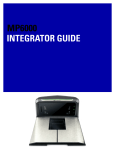
MP6000
INTEGRATOR GUIDE
MP6000
INTEGRATOR GUIDE
72E-172632-05
Revision A
July 2014
ii
MP6000 INTEGRATOR GUIDE
© 2013-2014 Motorola Solutions, Inc. All rights reserved.
No part of this publication may be reproduced or used in any form, or by any electrical or mechanical means,
without permission in writing from Motorola. This includes electronic or mechanical means, such as
photocopying, recording, or information storage and retrieval systems. The material in this manual is subject to
change without notice.
The software is provided strictly on an “as is” basis. All software, including firmware, furnished to the user is on
a licensed basis. Motorola grants to the user a non-transferable and non-exclusive license to use each
software or firmware program delivered hereunder (licensed program). Except as noted below, such license
may not be assigned, sublicensed, or otherwise transferred by the user without prior written consent of
Motorola. No right to copy a licensed program in whole or in part is granted, except as permitted under
copyright law. The user shall not modify, merge, or incorporate any form or portion of a licensed program with
other program material, create a derivative work from a licensed program, or use a licensed program in a
network without written permission from Motorola. The user agrees to maintain Motorola’s copyright notice on
the licensed programs delivered hereunder, and to include the same on any authorized copies it makes, in
whole or in part. The user agrees not to decompile, disassemble, decode, or reverse engineer any licensed
program delivered to the user or any portion thereof.
Motorola reserves the right to make changes to any software or product to improve reliability, function, or
design.
Motorola does not assume any product liability arising out of, or in connection with, the application or use of
any product, circuit, or application described herein.
No license is granted, either expressly or by implication, estoppel, or otherwise under any Motorola, Inc.,
intellectual property rights. An implied license only exists for equipment, circuits, and subsystems contained in
Motorola products.
MOTOROLA, MOTO, MOTOROLA SOLUTIONS and the Stylized M Logo are trademarks or registered
trademarks of Motorola Trademark Holdings, LLC and are used under license. All other trademarks are the
property of their respective owners.
Motorola Solutions, Inc.
One Motorola Plaza
Holtsville, New York 11742-1300
http://www.motorolasolutions.com
Warranty
Subject to the terms of Motorola’s hardware warranty statement, the MP6000 is warranted against defects in
workmanship and materials for a period of 1 (one) year from the date of shipment.
For the complete Motorola hardware product warranty statement, go to:
http://www.motorolasolutions.com/warranty
iii
Revision History
Changes to the original guide are listed below:
Change
Date
Description
-01 Rev A
6/2013
Initial Release.
-02 Rev A
6/2013
Added:
- Figure 3-43, Sensormatic Coil Routing
Updated:
- Figure 1-2, Left Side View
- Figure 3-44, Checkpoint Antenna Installation
- Figure A-2 callouts
- Checkpoint antenna routing color
-03 Rev A
12/2014
Added:
- NCR single cable scanner/scale, NCR scanner, Datalogic scanner only, and new
RS-232 bar codes.
- Support for third party hand-held scanners using USB auxiliary ports.
- RS-232 host connection to AUX 2 port (leaves USB host port available for future
use).
- Programmable scale initial zero setting range.
- IBM scale 3-byte status support.
- Volume button disable feature.
- Dual cable scale (SASI only).
- Wincor A/B, and RS-232 host interfaces (see Table 2-4 on page 2-15).
- USB HID keyboard interface.
- Drivers License Parsing (some models).
Updated:
- Host interface ports, and cables.
-04 Rev A
5/2014
Added:
- Third Party Scale bar codes.
- Price Computational Scale Interface circuit drawing.
- Mounting frame.
Updated:
- Added information to step 2 on page 4-7.
-05 Rev A
7/2014
Updated:
- Table A-1; E18, E25, E27 and E30 errors changed to warnings.
- From Active Mode 5.0 average, <12W peak to Active Mode 4.65 average, <12W
peak.
iv
MP6000 INTEGRATOR GUIDE
TABLE OF CONTENTS
Warranty ......................................................................................................................................... ii
Revision History .............................................................................................................................. iii
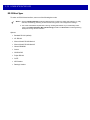
About This Guide
Introduction .....................................................................................................................................
Chapter Descriptions ......................................................................................................................
Notational Conventions...................................................................................................................
Related Publications .......................................................................................................................
Recommended Services Information..............................................................................................
v
v
vi
vi
vii
Chapter 1: PRODUCT OVERVIEW AND FEATURES
Introduction ....................................................................................................................................
Product Overview ...........................................................................................................................
Configurations ................................................................................................................................
Peripherals .....................................................................................................................................
Supported Auxiliary Hand-held Scanner ..................................................................................
EAS Devices ............................................................................................................................
Scale Devices ..........................................................................................................................
USB Flash Drives .....................................................................................................................
Customer Side Scanner (CSS) ................................................................................................
Features of the MP6000 ................................................................................................................
Features Summary ..................................................................................................................
1-1
1-2
1-3
1-8
1-8
1-8
1-8
1-8
1-8
1-9
1-13
Chapter 2: HOST INTERFACES AND CABLE PINOUTS
Overview ........................................................................................................................................
Interfaces, Components, and Communication ...............................................................................
POS Interfaces and Host Communication ...............................................................................
Auxiliary Ports and Peripherals ................................................................................................
Programming Management Tools ............................................................................................
Application Programming Interfaces ........................................................................................
Connecting a USB Interface ..........................................................................................................
2-1
2-2
2-2
2-2
2-3
2-3
2-4
vi
MP6000 INTEGRATOR GUIDE
USB Host Parameters ...................................................................................................................
USB Device Type .....................................................................................................................
Connecting an RS-232 Interface ...................................................................................................
MP6000 Scanner Only or MP6200/6500 Scale with Single Cable Protocol ............................
Price Computational Scale Interface Circuit Drawing ..............................................................
Connect MP6000 to RS-232 Host ............................................................................................
MP6000 with a Dual Cable Scanner/Scale ..............................................................................
RS-232 Parameters .......................................................................................................................
RS-232 Host Parameters ...............................................................................................................
RS-232 Host Types ..................................................................................................................
RS-232 Host -NCR Variant ................................................................................................
RS-232 Host -Datalogic Variant .........................................................................................
RS-232 Device Port Configuration ...........................................................................................
Third Party Scale Parameters ..................................................................................................
Third Party Scale ...............................................................................................................
Third Party Scale LED Pin .................................................................................................
Third Party Scale Zero Pin .................................................................................................
Connecting an IBM RS-485 Interface ............................................................................................
IBM RS-485 Host Parameters .......................................................................................................
IBM Scale Port Addresses .......................................................................................................
Connector Pins ..............................................................................................................................
RS-232 AUX 1 ...................................................................................................................
Scale Display Port ..............................................................................................................
RS-232 AUX 2 ...................................................................................................................
Checkpoint Interlock ..........................................................................................................
AUX A-B (Stacked USB) ....................................................................................................
POS ...................................................................................................................................
12V DC .............................................................................................................................
2-6
2-6
2-12
2-12
2-13
2-14
2-14
2-15
2-16
2-20
2-30
2-31
2-32
2-37
2-37
2-39
2-41
2-43
2-44
2-49
2-53
2-53
2-53
2-54
2-54
2-54
2-55
2-55
Chapter 3: SITE PREPARATION AND INSTALLATION
Overview ........................................................................................................................................
Site Preparation .............................................................................................................................
Ventilation and Spacing Requirements ....................................................................................
Service Access Requirements .................................................................................................
Electrical Power Considerations ..............................................................................................
Grounding ..........................................................................................................................
Checkstand Preparation ..........................................................................................................
Liquid Spills and Moisture ..................................................................................................
Vertical Clearance ..............................................................................................................
Tools ..................................................................................................................................
Counter Cutout ...................................................................................................................
Ergonomics ........................................................................................................................
Installing Components ...................................................................................................................
Quick Reference Installation Steps ..........................................................................................
Remove Existing Bioptic Scanner and Accessories ................................................................
Unpacking MP6000 Equipment ...............................................................................................
Pre-Installation Notes .........................................................................................................
Assemble the Dual Head Scale Display ..................................................................................
Required Tools ...................................................................................................................
Install the Scale Display ...........................................................................................................
3-1
3-2
3-2
3-2
3-3
3-3
3-4
3-4
3-4
3-4
3-5
3-5
3-6
3-6
3-7
3-7
3-8
3-9
3-9
3-12
Table of Contents
Getting Started ...................................................................................................................
Installing .............................................................................................................................
Cables and Connections ..........................................................................................................
Install the Customer Side Scanner (MX101) ............................................................................
Installing the MX101 on the Customer’s Right Side (Default) of the Tower Cover ............
Installing the MX101 on the Customer’s Left Side of the Tower Cover ..............................
Affixing the Identification Label ..........................................................................................
Install the MP6000 /Scale ........................................................................................................
Checkstand Counter Cutouts and MP6000 Dimensions ....................................................
Cutout/Dimensions - MP6000 Short ...................................................................................
Cutout/Dimensions - MP6000 Short (continued) ................................................................
Cutout/Dimensions - MP6000 Medium ..............................................................................
Cutout/Dimensions - MP6000 Long ...................................................................................
Install Sensormatic Coils ..........................................................................................................
Install Checkpoint Antenna ......................................................................................................
Trim Kit Installation (If Required) .............................................................................................
MP6000 Mounting Frame (If Required) ...................................................................................
3-14
3-15
3-15
3-16
3-17
3-21
3-23
3-24
3-24
3-25
3-26
3-27
3-29
3-33
3-35
3-36
3-37
Chapter 4: SCALE CALIBRATION (MODELS WITH A SCALE ONLY)
Overview ........................................................................................................................................
Scale Calibration Procedure (Scanner/Scale Configurations Only) ...............................................
Scale Configurations ................................................................................................................
Step 1 - Electronic Entry into Calibration Mode .......................................................................
Step 2 - Program Legal Parameters ........................................................................................
Legal Scale Units (Unit Selection) - Kilograms or Pounds .................................................
Important Notes ..................................................................................................................
Legal Scale Dampening Filter ............................................................................................
Step 3 - Calibration at NO LOAD .............................................................................................
Step 4 - Calibration at LOAD ...................................................................................................
Step 5 - Calibration Success or Failure ...................................................................................
Calibration Success ...........................................................................................................
Calibration Failure ..............................................................................................................
Possible Reasons for a Fail ...............................................................................................
Calibration Mode Exit Conditions .............................................................................................
Verification Test .......................................................................................................................
Audit Tallies .............................................................................................................................
Scale Configuration Parameters ....................................................................................................
Legal Scale Units .....................................................................................................................
Scale Display Configuration .....................................................................................................
Legal Scale Dampening Filter Setting ......................................................................................
User Interface Displays and Signals ..............................................................................................
4-1
4-2
4-2
4-3
4-3
4-3
4-3
4-4
4-4
4-4
4-7
4-7
4-7
4-7
4-7
4-8
4-11
4-12
4-12
4-14
4-16
4-20
Chapter 5: OPERATING THE SCANNER
Overview ........................................................................................................................................
Controls and Indicators ..................................................................................................................
LED Array Bar ..........................................................................................................................
Diagnostic LED/7-segment Display .........................................................................................
Front Panel Buttons .................................................................................................................
The three front panel user interface buttons are backlit for ease of use. ...........................
5-1
5-2
5-2
5-3
5-4
5-4
vii
viii
MP6000 INTEGRATOR GUIDE
Scale Zero Button (Configurations with Scale Only) ..........................................................
Volume/Tone Control Button ..............................................................................................
Sensormatic Manual Activation and Sensormatic Status Button .......................................
Soft Reset Buttons .............................................................................................................
MP6000 Related Hardware ...........................................................................................................
Scale Display (Scanner/Scale Configurations Only) ................................................................
Scale (Scanner/Scale Configurations Only) .............................................................................
Single Interval Range Scales .............................................................................................
Dual Interval Range Scales ...............................................................................................
Customer Side Scanner (CSS) - Optional ...............................................................................
Platter .......................................................................................................................................
Installing/Removing the Short and Medium Non-Scale Platters ........................................
Installing/Removing the Long Non-Scale and Medium Scale Platters ...............................
Installing/Removing the Long Scale Platter .......................................................................
Scan Windows .........................................................................................................................
Operating Modes ...........................................................................................................................
Programming the MP6000 .............................................................................................................
Programming Management tools .............................................................................................
Application Programming Interfaces ........................................................................................
Programming Bar Codes .........................................................................................................
USB Staging Flash Drive ...............................................................................................................
MP6000 Menu Structure for the USB Staging Flash Drive ......................................................
Manually Staging/Configuring MP6000 Devices ......................................................................
Loading Cloning Files ........................................................................................................
123Scan2 Staging Flash Drive Configuration ..........................................................................
Approved USB Flash Drives for the Flash Drive Well ..............................................................
Scanning ........................................................................................................................................
Weighing Items ..............................................................................................................................
Electronic Article Surveillance (EAS) .............................................................................................
Supported EAS Controllers ......................................................................................................
EAS Operating Modes and Settings ........................................................................................
Checkpoint Controller ..............................................................................................................
Sensormatic Controller ............................................................................................................
Sensormatic EAS Hard Tags ...................................................................................................
Sensormatic EAS Soft Tags (Labels) ......................................................................................
Beeper and LED Conditions ..........................................................................................................
5-4
5-4
5-5
5-5
5-6
5-6
5-6
5-6
5-6
5-6
5-7
5-7
5-7
5-8
5-9
5-10
5-10
5-10
5-10
5-10
5-11
5-11
5-12
5-13
5-14
5-14
5-15
5-16
5-17
5-17
5-17
5-18
5-18
5-18
5-19
5-20
Chapter 6: 123SCAN2
Introduction ....................................................................................................................................
Communication with 123Scan2 .....................................................................................................
123Scan2 Requirements ...............................................................................................................
Scanner SDK, Other Software Tools, and Videos .........................................................................
6-1
6-1
6-2
6-2
Appendix A: MAINTENANCE, TROUBLESHOOTING, AND ERROR CODES
Overview ........................................................................................................................................
Maintenance ..................................................................................................................................
Troubleshooting .............................................................................................................................
Diagnostic LED 7-segment Display - Error and Warning Codes .............................................
LED Display Notes ...................................................................................................................
A-1
A-1
A-2
A-2
A-2
Table of Contents
Status Indicator Light ...............................................................................................................
Troubleshooting Assistance .....................................................................................................
General Error and Warning Codes ..........................................................................................
Scale Warning Codes ..............................................................................................................
A-2
A-3
A-5
A-6
Appendix B: TECHNICAL SPECIFICATIONS
Technical Specifications ................................................................................................................ B-1
Appendix C: HOST INTERFACE CHARACTER SETS
Introduction .................................................................................................................................... C-1
RS-232 Character Sets .................................................................................................................. C-2
Appendix D: PARAMETER DEFAULT TABLE
Index
ix
x
MP6000 INTEGRATOR GUIDE
ABOUT THIS GUIDE
Introduction
The MP6000 Integrator Guide provides information on installing, operating, and programming the MP6000.
Chapter Descriptions
Following are brief descriptions of each chapter in this guide.
• Chapter 1, PRODUCT OVERVIEW AND FEATURES provides an overview of the MP6000 including
configurations, peripherals, and features.
• Chapter 2, HOST INTERFACES AND CABLE PINOUTS describes the host interfaces supported by the
MP6000, how to connect the MP6000 to a host, setup, and cable pin-outs. It also includes host interface bar
codes.
• Chapter 3, SITE PREPARATION AND INSTALLATION describes how to install the MP6000 into a counter
top.
• Chapter 4, SCALE CALIBRATION (MODELS WITH A SCALE ONLY) describes how to change weight
measurement, calibrate the scale, verify calibration, and recognize errors.
• Chapter 5, OPERATING THE SCANNER describes how to operate the MP6000 including buttons, switches,
LED indicators, and scanning.
• Chapter 6, 123SCAN2 provides information about configuring the MP6000 using the 123Scan2 utility.
• Appendix A, MAINTENANCE, TROUBLESHOOTING, AND ERROR CODES provides error/warning codes,
troubleshooting, and maintenance information.
• Appendix B, TECHNICAL SPECIFICATIONS provides technical information about the MP6000.
• Appendix C, HOST INTERFACE CHARACTER SETS provides ASCII character sets for some host
interfaces.
Notational Conventions
This document uses these conventions:
vi
MP6000 INTEGRATOR GUIDE
• “User” refers to anyone operating the device.
• “Device” refers to the MP6000.
• Italics are used to highlight specific items in the general text, and to identify chapters and sections in this
and related documents. It also identifies names of windows, menus, menu items, and fields within
windows.
• Bold identifies buttons, and switches to be tapped or clicked, and bar code names.
• Bullets (•) indicate:
• lists of alternatives or action items.
• lists of required steps that are not necessarily sequential.
• Numbered lists indicate a set of sequential steps, i.e., those that describe step-by-step procedures.
NOTE
This symbol indicates something of special interest to the reader. Failure to read the note will not result in
physical harm to the bar code reader, equipment or data.
IMPORTANT This symbol indicates something of importance to the reader. Failure to read the note may impair
the equipment or data.
CAUTION
WARNING!
This symbol indicates that if this information is ignored, the possibility of data or material damage
may occur.
This symbol indicates that if this information is ignored the possibility that serious
personal injury may occur.
Related Publications
Following is a list of documents that provide additional information about configuring the MP6000:
• MP6000 BAR CODE PROGRAMMING GUIDE,
p/n 72E-172633-xx, provides bar codes for MP6000 configuration.
• MX101 PRODUCT REFERENCE GUIDE, p/n 72E-171320-xx, provides general instructions for setting
up, operating, maintaining, and troubleshooting the MX101 digital scanner.
• MP6000 MULTI-PLANE IMAGING SCANNER REGULATORY GUIDE, p/n 72-171321-xx, provides
domestic and international regulatory information.
• Advanced Data Formatting Programmer Guide, p/n 72E-69680-xx, provides information on ADF, a
means of customizing data before transmission to a host.
For the latest version of this guide and all Motorola Solutions guides, go to:
http://www.motorolasolutions.com/support
Recommended Services Information
If you have a problem using the equipment, contact your facility's technical or systems support. If there is a
problem with the equipment, they will contact the Motorola Solutions Global Customer Support Center at:
http://www.motorolasolutions.com/support
About This Guide
vii
When contacting Motorola Solutions support, please have the following information available:
• Serial number of the unit
• Model number or product name
• Software type and version number (if available).
Motorola responds to calls by e-mail, telephone or fax within the time limits set forth in service agreements.
If your problem cannot be solved by the Motorola Solutions Global Customer Support Center, you may need to
return your equipment for servicing and will be given specific directions, a Field Service Technician from
Motorola, or your authorized service provider may be sent to your location to perform the repair, depending on
your level of entitlement set forth in the service agreement. Motorola is not responsible for any damages
incurred during shipment if the approved shipping container is not used. Shipping the units improperly can
possibly void the warranty.
If you purchased your business product from a Motorola business partner, please contact that business partner
for support.
Motorola recommends the following Service options to keep the MP6000 operating at peak performance
throughout its lifecycle:
• Service from the Start with Advance Exchange Support (available for scanner-only configurations).
• Service from the Start with On Site System Support (available for scanner-only and scanner/scale
configurations).
• Motorola also offers service support through authorized resellers who qualify as authorized service
partners.
viii
MP6000 INTEGRATOR GUIDE
CHAPTER 1 PRODUCT OVERVIEW AND
FEATURES
Introduction
This chapter includes the following topics:
• Product Overview on page 1-2
• Configurations on page 1-3
• Peripherals on page 1-8
• Features of the MP6000 on page 1-9.
1-2
MP6000 INTEGRATOR GUIDE
Product Overview
The MP6000 is a data capture solution that uses a sophisticated optical arrangement to view six sides of an
object as it passes through the scanning area. Bar code data is transmitted to a Point-Of-Sale (POS) host via
USB, RS-232, or RS-485. Auxiliary device support includes USB and RS-232 hand-held scanners, Checkpoint
and Sensormatic Electronic Article Surveillance (EAS), scale and optional Scale Display (varies with the
model), USB staging flash drive (memory stick), as well as an optional Customer Side Scanner (2D imager)
that may be mounted into the tower.
The MP6000 is designed to be embedded in a cutout in the retail checkstand.
Features include:
• Six sided scanning
• Reads top-bottom, left-right, and cashier-customer side bar codes
• Omni-directional symbol orientation.
• Optional integrated scale (single/dual interval).
• Optional Checkpoint EAS antenna.
• Optional integrated Sensormatic EAS coil antennas.
• Optional Scale Display (single/dual head) for scale installations.
• Auxiliary scanner support (USB and RS-232).
• High swipe speed for increased throughput.
• User interface (LED indicators, touch controls, audio).
• Aggressive scanning performance on high density, truncated, and poorly printed bar codes.
• 2D scanning (PDF, Aztec etc.) in both vertical and horizontal windows, or all six-sided orientations.
• Mobile bar code scanning (cell phone) in both vertical and horizontal windows, or all six-sided
orientations.
• Optional integrated Customer Side Scanner (CSS) [1D/2D support].
• Scanner Management Service (SMS), and 123Scan² support enables remote configuration and
monitoring attached peripherals.
PRODUCT OVERVIEW AND FEATURES
1-3
Configurations
The MP6000 captures printed or mobile 1D or 2D bar codes. An optional customer-side scanner (CSS) can be
added for bar codes displayed on mobile phones, traditional loyalty cards, or item bar codes. Hand-held
scanner, integrated EAS, and scale support is also available.
This guide covers the configurations listed in Table 1-1.
NOTE
1. All configurations of the MP6000 include a sapphire glass horizontal platter.
2. New scale configurations are added continually. If you don’t see your country listed, call your
Motorola Solutions office.
Table 1-1 MP6000 Configurations
Configuration
Description
MP6000-LN000M010US
Multi-plane scanner, long, with Checkpoint, worldwide.
MP6000-LP000M010US
Multi-plane scanner, long, with Checkpoint, with DL Parsing, US/CA.
MP6000-MN000M010US
Multi-plane scanner, medium, with Checkpoint, worldwide.
MP6000-MP000M010US
Multi-plane scanner, medium, with Checkpoint, with DL Parsing, US/CA.
MP6000-SN000M010US
Multi-plane scanner, short, with Checkpoint, worldwide.
MP6000-SP000M010US
Multi-plane scanner, short, with Checkpoint, with DL Parsing, US/CA.
MP6010-LN000M010US
Multi-plane scanner, long, with Checkpoint, with CSS, worldwide.
MP6010-LP000M010US
Multi-plane scanner, long, with Checkpoint, with DL Parsing, US/CA.
MP6010-MN000M010US
Multi-plane scanner, medium, with Checkpoint, with CSS, worldwide.
MP6010-MP000M010US
Multi-plane scanner, medium, with Checkpoint, with DL Parsing, US/CA.
MP6010-SN000M010US
Multi-plane scanner, short, with Checkpoint, with CSS, worldwide.
MP6010-SP000M010US
Multi-plane scanner, short, with Checkpoint, with DL Parsing, US/CA.
MP6200-LN000M010AU
Multi-plane scanner, long, with single interval scale, with Checkpoint, scale for
Australia/NZ/SA.
MP6200-LN000M010CM
Multi-plane scanner, long, single interval kg scale, no CSS, Checkpoint,
Canada-Mexico scale label.
MP6200-LN000M010EU
Multi-plane scanner, long, with single interval scale, with Checkpoint, scale for
EU countries.
Notes:
1. EU scales are legally accepted in the following countries:
Austria, Belgium, Bulgaria, Cyprus, Czech Republic, Denmark, Estonia, Finland, France,
Germany, Greece, Hungary, Ireland, Iceland, Italy, Liechtenstein, Lithuania, Luxembourg, Latvia,
Malta, Netherlands, Norway, Poland, Portugal, Romania, Slovak Republic, Spain, Sweden,
Switzerland, United Kingdom
2. OIML scales are legally accepted in the following countries:
Barbados, Belize, Bermuda, Chile, Colombia, Costa Rica, El Salvador, Guatemala, Hong Kong,
Jamaica, Saint Lucia, Philippines, Thailand, Trinidad and Tobago, Vietnam
1-4
MP6000 INTEGRATOR GUIDE
Table 1-1 MP6000 Configurations (Continued)
Configuration
Description
MP6200-LN000M010NN
Multi-plane scanner, long, with single interval scale, with Checkpoint, scale for
OIML countries.
MP6200-LN000M010US
Multi-plane scanner, long, with single interval scale, with Checkpoint, scale for
US/Puerto Rico/Guam/USVI/British VI.
MP6200-LN000M01ABE
Multi-plane scanner, Long with single interval kg scale, with Checkpoint, scale
Gravity Zone A for Belgium.
MP6200-LN000M01BBE
Multi-plane scanner, Long with single interval kg scale, with Checkpoint, scale
Gravity Zone B for Belgium.
MP6200-LN000M01CBE
Multi-plane scanner, Long with single interval kg scale, with Checkpoint, scale
Gravity Zone C for Belgium.
MP6200-LP000M010US
Multi-plane scanner, long, with single interval scale, with Checkpoint, with DL
parsing, scale for US.
MP6200-MN000M010AU
Multi-plane scanner, medium, with single interval scale, with Checkpoint, scale
for Australia/NZ/SA.
MP6200-MN000M010CM
Multi-plane scanner, medium, single interval kg scale, no CSS, Checkpoint,
Canada-Mexico scale label.
MP6200-MN000M010EU
Multi-plane scanner, medium, with single interval scale, with Checkpoint, scale
for EU countries.
MP6200-MN000M010NN
Multi-plane scanner, medium, with single interval scale, with Checkpoint, scale
for OIML countries.
MP6200-MN000M010US
Multi-plane scanner, medium, with single interval scale, with Checkpoint, scale
for US/Puerto Rico/Guam/USVI/British VI.
MP6200-MN000M01ABE
Multi-plane scanner, Medium with single interval kg scale, with Checkpoint,
scale Gravity Zone A for Belgium.
MP6200-MN000M01BBE
Multi-plane scanner, Medium with single interval kg scale, with Checkpoint,
scale Gravity Zone B for Belgium.
MP6200-MN000M01CBE
Multi-plane scanner, Medium with single interval kg scale, with Checkpoint,
scale Gravity Zone C for Belgium.
MP6200-MP000M010US
Multi-plane scanner, medium, with single interval scale, with Checkpoint, with
DL parsing, scale for US.
MP6210-LN000M010AU
Multi-plane scanner, long, with single interval scale, with Checkpoint, with
CSS, scale for Australia/NZ/SA.
Notes:
1. EU scales are legally accepted in the following countries:
Austria, Belgium, Bulgaria, Cyprus, Czech Republic, Denmark, Estonia, Finland, France,
Germany, Greece, Hungary, Ireland, Iceland, Italy, Liechtenstein, Lithuania, Luxembourg, Latvia,
Malta, Netherlands, Norway, Poland, Portugal, Romania, Slovak Republic, Spain, Sweden,
Switzerland, United Kingdom
2. OIML scales are legally accepted in the following countries:
Barbados, Belize, Bermuda, Chile, Colombia, Costa Rica, El Salvador, Guatemala, Hong Kong,
Jamaica, Saint Lucia, Philippines, Thailand, Trinidad and Tobago, Vietnam
PRODUCT OVERVIEW AND FEATURES
1-5
Table 1-1 MP6000 Configurations (Continued)
Configuration
Description
MP6210-LN000M010CM
Multi-plane scanner, long, single interval kg scale, with CSS, Checkpoint,
Canada-Mexico scale label.
MP6210-LN000M010EU
Multi-plane scanner, long, with single interval scale, with Checkpoint, with
CSS, scale for EU countries.
MP6210-LN000M010NN
Multi-plane scanner, long, with single interval scale, with Checkpoint, with
CSS, scale for OIML countries.
MP6210-LN000M010US
Multi-plane scanner, long, with single interval scale, with Checkpoint, with
CSS, scale for US/Puerto Rico/Guam/USVI/British VI.
MP6210-LN000M01ABE
Multi-plane scanner, Long with single interval kg scale, with CSS, with
Checkpoint, scale Gravity Zone A for Belgium.
MP6210-LN000M01BBE
Multi-plane scanner, Long with single interval kg scale, with CSS, with
Checkpoint, scale Gravity B for Belgium.
MP6210-LN000M01CBE
Multi-plane scanner, Long with single interval kg scale, with CSS, with
Checkpoint, scale Gravity Central C for Belgium.
MP6210-LP000M010US
Multi-plane scanner, long, with single interval scale, with Checkpoint, with
CSS, with DL parsing, scale for US.
MP6210-MN000M010AU
Multi-plane scanner, medium, with single interval scale, with Checkpoint, with
CSS, scale for Australia/NZ/SA.
MP6210-MN000M010CM
Multi-plane scanner, medium, single interval kg scale, with CSS, Checkpoint,
Canada-Mexico scale label.
MP6210-MN000M010EU
Multi-plane scanner, medium, with single interval scale, with Checkpoint, with
CSS, scale for EU countries.
MP6210-MN000M010NN
Multi-plane scanner, medium, single interval scale, with Checkpoint, with CSS,
scale for OIML countries.
MP6210-MN000M010US
Multi-plane scanner, medium, with single interval scale, with Checkpoint, with
CSS, scale for US/Puerto Rico/Guam/USVI/British VI.
MP6210-MN000M01ABE
Multi-plane scanner, Medium with single interval kg scale, with CSS, with
Checkpoint, scale Gravity Zone A for Belgium.
MP6210-MN000M01BBE
Multi-plane scanner, Medium with single interval kg scale, with CSS, with
Checkpoint, scale Gravity Zone B for Belgium.
MP6210-MN000M01CBE
Multi-plane scanner, Medium with single interval kg scale, with CSS, with
Checkpoint, scale Gravity Zone C for Belgium.
Notes:
1. EU scales are legally accepted in the following countries:
Austria, Belgium, Bulgaria, Cyprus, Czech Republic, Denmark, Estonia, Finland, France,
Germany, Greece, Hungary, Ireland, Iceland, Italy, Liechtenstein, Lithuania, Luxembourg, Latvia,
Malta, Netherlands, Norway, Poland, Portugal, Romania, Slovak Republic, Spain, Sweden,
Switzerland, United Kingdom
2. OIML scales are legally accepted in the following countries:
Barbados, Belize, Bermuda, Chile, Colombia, Costa Rica, El Salvador, Guatemala, Hong Kong,
Jamaica, Saint Lucia, Philippines, Thailand, Trinidad and Tobago, Vietnam
1-6
MP6000 INTEGRATOR GUIDE
Table 1-1 MP6000 Configurations (Continued)
Configuration
Description
MP6210-MP000M010US
Multi-plane scanner, medium, with single interval scale, with Checkpoint, with
CSS, with DL parsing, scale for US.
MP6500-LN000M010CM
Multi-plane scanner, long, with dual interval scale, with Checkpoint, scale for
Canada/Mexico.
MP6500-LN000M010EU
Multi-plane scanner, long, with dual interval scale, with Checkpoint, scale for
EU.
MP6500-LN000M010NN
Multi-plane scanner, long, with dual interval scale, with Checkpoint, scale for
NN.
MP6500-LN000M010US
Multi-plane scanner, long, with dual interval scale, with Checkpoint, scale for
US.
MP6500-LP000M010US
Multi-plane scanner, long, with dual interval scale, Drivers License Parsing,
with Checkpoint, scale for US.
MP6500-MN000M010CM
Multi-plane scanner, medium, with dual interval scale, with Checkpoint, scale
for Canada/Mexico.
MP6500-MN000M010EU
Multi-plane scanner, long, with dual interval scale, with Checkpoint, scale for
EU.
MP6500-MN000M010NN
Multi-plane scanner, medium, with dual interval scale, with Checkpoint, scale
for NN.
MP6500-MN000M010US
Multi-plane scanner, medium, with dual interval scale, with Checkpoint, scale
for US.
MP6500-MP000M010US
Multi-plane scanner, medium, with dual interval scale, Drivers License Parsing,
with Checkpoint, scale for US.
MP6510-LN000M010CM
Multi-plane scanner, long, with dual interval scale, with Checkpoint, with CSS,
scale for Canada/Mexico.
MP6510-LN000M010EU
Multi-plane scanner, long, with dual interval scale, with Checkpoint, with CSS,
scale for EU.
MP6510-LN000M010NN
Multi-plane scanner, long, with dual interval scale, with Checkpoint, with CSS,
scale for NN.
MP6510-LN000M010US
Multi-plane scanner, long, with dual interval scale, with Checkpoint, with CSS,
scale for US.
MP6510-LP000M010US
Multi-plane scanner, long, with dual interval scale, Drivers License Parsing,
with Checkpoint, with CSS, scale for US.
Notes:
1. EU scales are legally accepted in the following countries:
Austria, Belgium, Bulgaria, Cyprus, Czech Republic, Denmark, Estonia, Finland, France,
Germany, Greece, Hungary, Ireland, Iceland, Italy, Liechtenstein, Lithuania, Luxembourg, Latvia,
Malta, Netherlands, Norway, Poland, Portugal, Romania, Slovak Republic, Spain, Sweden,
Switzerland, United Kingdom
2. OIML scales are legally accepted in the following countries:
Barbados, Belize, Bermuda, Chile, Colombia, Costa Rica, El Salvador, Guatemala, Hong Kong,
Jamaica, Saint Lucia, Philippines, Thailand, Trinidad and Tobago, Vietnam
PRODUCT OVERVIEW AND FEATURES
1-7
Table 1-1 MP6000 Configurations (Continued)
Configuration
Description
MP6510-MN000M010CM
Multi-plane scanner, medium, with dual interval scale, with Checkpoint, with
CSS, scale for Canada/Mexico.
MP6510-MN000M010EU
Multi-plane scanner, medium, with dual interval scale, with Checkpoint, with
CSS, scale for EU.
MP6510-MN000M010NN
Multi-plane scanner, medium, with dual interval scale, with Checkpoint, with
CSS, scale for NN.
MP6510-MN000M010US
Multi-plane scanner, medium, with dual interval scale, with Checkpoint, with
CSS, scale for US.
MP6510-MP000M010US
Multi-plane scanner, medium, with dual interval scale, Drivers License Parsing,
with Checkpoint, with CSS, scale for US.
Notes:
1. EU scales are legally accepted in the following countries:
Austria, Belgium, Bulgaria, Cyprus, Czech Republic, Denmark, Estonia, Finland, France,
Germany, Greece, Hungary, Ireland, Iceland, Italy, Liechtenstein, Lithuania, Luxembourg, Latvia,
Malta, Netherlands, Norway, Poland, Portugal, Romania, Slovak Republic, Spain, Sweden,
Switzerland, United Kingdom
2. OIML scales are legally accepted in the following countries:
Barbados, Belize, Bermuda, Chile, Colombia, Costa Rica, El Salvador, Guatemala, Hong Kong,
Jamaica, Saint Lucia, Philippines, Thailand, Trinidad and Tobago, Vietnam
1-8
MP6000 INTEGRATOR GUIDE
Peripherals
The MP6000 supports the peripheral devices listed below.
Supported Auxiliary Hand-held Scanner
The MP6000 provides auxiliary data ports (USB and RS-232) to which a hand-held scanner can be connected.
NOTE
An auxiliary cordless scanner, such as the LI4278, LS4278, or DS6878, can be attached to the MP6000. If
a presentation cradle is used with any of these scanners, a separate cradle power supply is required.
IMPORTANT The MP6000 scanner does not configure an auxiliary scanner. Auxiliary scanners must be
configured separately, independently of the MP6000 scanner.
EAS Devices
• Sensormatic AMB-9010 controller (available December 2014)
• Sensormatic AMB-9010-IPS controller
• Sensormatic ScanMax-Pro controller
• Checkpoint controller
• Checkpoint with interlock controller.
See Electronic Article Surveillance (EAS) on page 5-17 for detailed information.
Scale Devices
• OEM standard scale
• Single/dual head Scale Displays.
• Mettler-Toledo price computing scale for parts of Europe (available September 2014).
USB Flash Drives
• Typical USB flash drive with Type A connector. (See USB Staging Flash Drive on page 5-11.)
Customer Side Scanner (CSS)
• The CSS (MX101) is an optional integrated device that supports 1D and 2D bar code scanning. The CSS
unit replaces the MP6000 tower cover, and can be installed on either side of the MP6000. Refer to the
MX101 PRODUCT REFERENCE GUIDE, p/n 72E-171320-xx, for installation and configuration
information.
PRODUCT OVERVIEW AND FEATURES
1-9
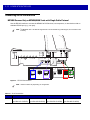
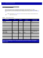
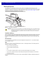
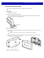
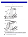
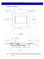
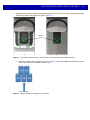
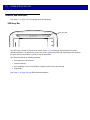
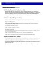
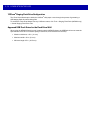
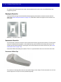
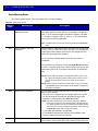
Features of the MP6000
The following illustrations of the medium model show the features of the MP6000. See Table 1-2 on page 1-13
for brief descriptions of all features. See Controls and Indicators on page 5-2 for detailed descriptions of each
feature.
NOTE
Refer to the MX101 Product Reference Guide (p/n 72E-171320-xx) for information about the optional
Customer Side Scanner (CSS). The CSS is shown in its default (left side) position, but it can be moved to
the other side at any time - no tools required.
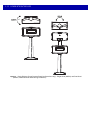
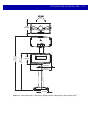
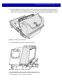
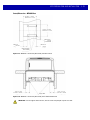
Optional CSS
CSS Scan
Window
MP6000
LED Array Bar
Vertical Scan
Window
Speaker
Platter
Scale Zero
Button
Volume/Tone
Control Button
EAS
Deactivation
Button
(Sensormatic
only)
Horizontal
Scan
Window
Scale
(optional)
7-segment
Display
Figure 1-1 CSS and MP6000 Front View
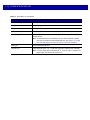
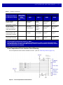
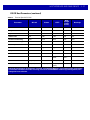
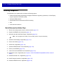
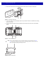
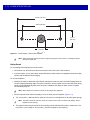
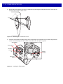
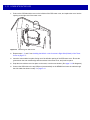
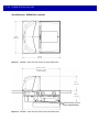
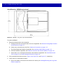
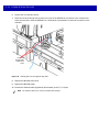
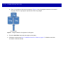
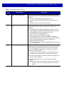
1 - 10 MP6000 INTEGRATOR GUIDE
Tower
Cover
Tower Bezel
EAS Cable Channel
(also see Figure 3-43 on page 3-34 for
Sensormatic coil routing)
Drainage/Ventilation Holes
Scale Cable Channel
Figure 1-2 Left Side View
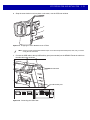
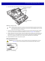
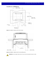
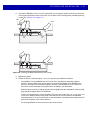
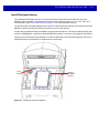
CSS Cable
Channels
Drainage/Ventilation Holes
Strain Relief
Groove (for
cables)
RS-232
AUX 1
0.0
Scale
Display
RS-232
AUX 2
Figure 1-3 Right Side View/Connector Ports
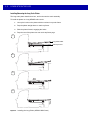
CKP
I-LOCK 1
AUX
A-B 2
POS
12V
DC
1
Checkpoint Interlock Port
2
Auxiliary USB Ports
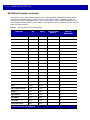
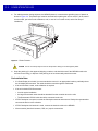
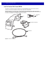
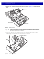
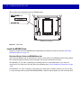
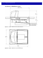
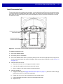
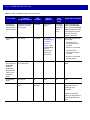
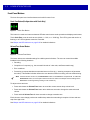
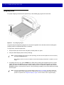
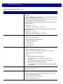
PRODUCT OVERVIEW AND FEATURES 1 - 11
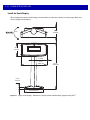
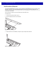
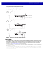
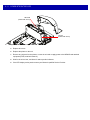
Staging USB Flash
Drive Cap/Port
Optional Scale
(scale is not available in
MP6000 short models)
Figure 1-4 View Under Platter
Leveling Screw Access Holes
(medium and short units only)
NOTE
The tower bezel must be
removed, and the Tower
Cover slid backwards to
access the leveling screws.
1
Leveling screws are an
optional accessory.
4 Leveling Screws (2 screws on opposite side) 1
Figure 1-5 Leveling Screws
To use leveling screws, buy
accessory kit
MX301-SR00004ZZWR for
standard-length screws, or
accessory kit
MX302-SR00004ZZWR for 1
in. (25 mm) extra length.
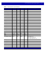
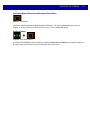
1 - 12 MP6000 INTEGRATOR GUIDE
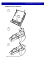
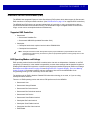
o
290
o
290
Figure 1-6 Scale Displays (Some Scanner/Scale Configurations Only) - Single Head (MX201) and Dual Head
(MX202; additional head added during installation)
PRODUCT OVERVIEW AND FEATURES 1 - 13
Features Summary
Table 1-2 Features on the MP6000
Feature
Description
Page
Diagnostic LED/7-segment Display
Internal display provides detailed status,
troubleshooting information, and scale legal
parameters during calibration.
5-3
LED Array Bar
Provides visual feedback for system statuses
and alerts.
5-2
Scale Zero Button
Scale status LED and touch button provides
scale status, and allows user to "zero" the scale.
5-4
Volume/Tone Control Button
User selectable settings for audible system
indications. (Status LED and button.)
5-4
EAS Deactivation Button (Sensormatic only)
Indicates the state of the Sensormatic EAS
device, and controls manual deactivation
(optional).
5-5
Scale (Optional/ Scanner Scale
Configurations Only)
Scales are available for the medium length and
long length configurations.
5-6
Platter
Stainless steel horizontal scanning surface;
imaging window for processing bar code data,
and placing items on the surface to determine
weight.
5-7
Calibration Switch
Used in manual scale calibration (currently
unavailable).
n/a
CSS (Optional)
Modular unit that fits into the MP6000 tower;
used for customer scanning.
5-6
Scale Display
Single or dual display option provides the weight
of items on the scale.
5-6
Leveling Screws (medium and short models
only)
Screws for leveling the MP6000 when shelf
mounting is required. Leveling screws are an
optional accessory.
1-11
Connectors
Connect the MP6000 to peripherals, and
POS/host.
Table 1-3
Internal USB Cap/Port
The internal USB port is available under the
platter.
1-11
EAS Cable Channel
Cable routing channel for EAS antennas.
1-10
Scale Cable Channel
Cable routing channel for the scale cable.
1-10
Drainage/Ventilation Holes
Outlet for spills.
1-10
CSS Cable Channels
Channels for routing CSS cables.
1-10,
3-16
1 - 14 MP6000 INTEGRATOR GUIDE
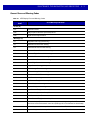
Table 1-3 Description of Connectors
Port
Description
RS-232 AUX 1 (J7)
See Table 2-3 on page 2-13 for description.
0.0 (J6)
Scale Display port.
RS-232 AUX 2 (J5)
See Table 2-3 on page 2-13 for description.
CKP I-LOCK (J4)
Checkpoint EAS Interlock.
AUX A-B (J3)
Dual USB 2.0 full speed ports for auxiliary USB scanners, CSS, or mass
storage device.
NOTE
POS (J2)
12V DC (J1)
An additional USB port is available in the front under the platter. All USB
ports can be used for the USB staging flash drive. See Table 2-14 on page
2-54 and USB Staging Flash Drive on page 5-11 for more information.
Point of Sale terminal port.
External power input. 12V / 3.33A (not required if powered from terminal).
NOTE
If a power supply plug is inserted to the J1 connector, with no voltage to the
power supply, the scanner will not power up.
CHAPTER 2 HOST INTERFACES AND CABLE
PINOUTS
Overview
This chapter describes the host interfaces supported by the MP6000, and how to connect the MP6000 to a
host. It also include host interface bar codes. See Figure 1-1 on page 1-9 for locations of the interface
connectors.
OPOS/JAVAPOS settings are outside the scope of this guide. For the Motorola Solutions SDK, go to:
www.motorolasolutions.com/windowssdk.
2-2
MP6000 INTEGRATOR GUIDE
Interfaces, Components, and Communication
The MP6000 supports the following.
POS Interfaces and Host Communication
IMPORTANT Avoid inserting a POS cable in the AUX 1 or AUX 2 port.
• USB 2.0 full speed using Motorola USB multi-host cables
• RS-232 connection using several communication protocols.
• RS-485 communication protocol.
Auxiliary Ports and Peripherals
• Three USB 2.0 full speed auxiliary ports (see AUX A-B (Stacked USB) on page 2-54).
• Two RS-232 auxiliary ports (AUX 1/AUX 2; see Figure 1-3 on page 1-10).
The MP6000 can support the following combinations of peripherals:
• Hand-held scanners supported in USB mode, or RS-232 mode.
• CSS (CSS is USB only).
NOTE
A total of one hand-held scanner plus one CSS is supported.
• Wireless auxiliary scanner support may be provided via a corded cradle as an auxiliary device.
An auxiliary cordless scanner, such as the LI4278, LS4278, or DS6878, can be attached to the MP6000. If a
standard cradle is used with the DS6878, a separate cradle power supply is required.
• Sensormatic controller via the RS-232 auxiliary port.
IMPORTANT Use only Motorola approved cables when connecting peripherals to the ports on the MP6000.
• Dual cable scanner/scale: Via RS-232 AUX 1, or RS-232 AUX 2 ports (see Figure 1-3 on page 1-10, and
Table 2-3 on page 2-13).
HOST INTERFACES AND CABLE PINOUTS
2-3
Programming Management Tools
• 123Scan2 (see Chapter 6, 123SCAN2)
• SMS
• Staging flash drive reprogramming (USB memory stick)
NOTE
Only Motorola hand-held scanners can be managed via 123Scan2 (see Chapter 6, 123SCAN2), and SMS
through the MP6000 scanner.
Application Programming Interfaces
• Motorola scanner SDK APIs (CoreScanner APIs)
• Motorola scanner OPOS/JPOS APIs.
For access to these programming interfaces, go to: www.motorolasolutions.com/windowssdk.
NOTE
If the MP6000 is powered up with no interface cable present, it reverts to “no host mode.” This is useful for
demonstrations where no host is present.
2-4
MP6000 INTEGRATOR GUIDE
Connecting a USB Interface
The MP6000 connects directly to a USB host. An additional power supply may be required
(PWRS-14000-148R). Only a USB Power Plus host can power the MP6000 using a Motorola Power Plus
cable, without an external power supply.
AUX
A-B
POS
12V
DC
Figure 2-1 USB Connections
NOTE
Interface cables vary depending on configuration.
There are three possible USB connection methods for the MP6000:
• POS connection using USB Power Plus (12V); requires a CBA-U52-S16PAR cable between POS
equipment (e.g., IBM) and the MP6000 POS RJ-45 connector. The MP6000 is a USB device for this
connection; no power supply is required (the MP6000 draws power from USB cable).
• POS connection using USB Standard A (5V); requires a CBA-U51-S16ZAR cable between POS
equipment (standard device - PC) and MP6000 POS RJ-45 connector. The MP6000 is USB device but
requires an external power supply (MP6000 does NOT draw power from USB cable).
• AUX scanner connection using a Motorola USB hand-held scanner; requires a Motorola USB type A
cable between the Motorola USB hand-held scanner (RJ-45), and the MP6000 AUX A-B USB port. The
MP6000 is the USB host, and the Motorola scanner is the USB device which draws power from 5V cable.
HOST INTERFACES AND CABLE PINOUTS
2-5
To set up the MP6000:
1.
Connect the RJ-45 modular connector of the USB interface cable to the POS interface port on the
MP6000.
2.
Plug the series A connector, or the Power Plus connector in the USB host. If Power Plus is used, the
MP6000 powers up with the POS.
3.
If no Power Plus is used, connect a 12V power supply. Connecting the 12V power supply immediately
turns the unit on.
4.
Select the USB device type by scanning the appropriate bar code (see USB Device Type on page 2-6).
5.
To modify any parameter options:
a.
Scan the appropriate bar codes in the MP6000 Bar Code Programming Guide, p/n 72E-172633-xx.
or
b.
Use 123Scan2.
or
c.
Use the 123Scan2 2D configuration bar code.
or
d.
Use a USB staging flash drive (see USB Staging Flash Drive on page 5-11).
2-6
MP6000 INTEGRATOR GUIDE
USB Host Parameters
USB Device Type
To select a USB device type, scan one of the bar codes listed in Table 2-1.
NOTE 1. When changing USB device types, the MP6000 automatically resets and issues the standard startup
beep sequences.
2. Before selecting CDC COM Port Emulation, install the Motorola USB CDC driver on the host to ensure
the scanner does not stall during power up (due to a failure to enumerate USB). If the scanner stalls,
recover it by installing the CDC INF file, and reboot the MP6000.
NOTE
This guide includes limited parameter bar codes. For ALL MP6000 programming bar codes, refer to the
MP6000 Bar Code Programming Guide (p/n 72E-172633-xx).
Table 2-1 USB Host Parameters
Parameter
Page
Number
USB Device Type
IBM Table-top USB (default)
2-7
IBM Hand-held USB
2-8
IBM OPOS
(IBM Hand-held USB with Full Scan Disable)
2-9
HID Keyboard Emulation
2-10
CDC COM Port Emulation
2-11
HOST INTERFACES AND CABLE PINOUTS
USB Device Type (continued)
* IBM Table-top USB
2-7
2-8
MP6000 INTEGRATOR GUIDE
USB Device Type (continued)
IBM Hand-held USB
HOST INTERFACES AND CABLE PINOUTS
USB Device Type (continued)
IBM OPOS
(IBM Hand-held USB with Full Scan Disable)
2-9
2 - 10 MP6000 INTEGRATOR GUIDE
USB Device Type (continued)
When the HID Keyboard host is selected, and the MP6000 has auxiliary scanners connected, use ADF rules to
program the auxiliary scanners to add a 500 msec pause to the end of the data to prevent the interleaving of bar
code data from multiple scanners. This works with standard RS-232, and SSI over RS-232 (with the Send Raw
Decode Data setting).
HID Keyboard Emulation
HOST INTERFACES AND CABLE PINOUTS 2 - 11
USB Device Type (continued)
CDC COM Port Emulation
2 - 12 MP6000 INTEGRATOR GUIDE
Connecting an RS-232 Interface
MP6000 Scanner Only or MP6200/6500 Scale with Single Cable Protocol
Use the RS-232 interface to connect the MP6000 to POS devices, host computers, or other devices with an
available RS-232 port (e.g., com port).
NOTE
The MP6000 uses +/-6V RS-232 signal levels to accommodate long cable lengths, and increased noise
immunity.
RS-232
AUX 1
RS-232
AUX 2
POS
12V
DC
Figure 2-2 RS-232 Connections.
NOTE
Interface cables vary depending on configuration.
Table 2-2 Host Connections
Port
POS
Connection Options
Unpowered USB
(p/n CBA-U51-S16ZAR)
Powered USB
(p/n CBA-U52-S16PAR)
RS-232
(p/n CBA-R51-S16ZAR)
RS-485
(p/n CBA-M51-S16PAR)
HOST INTERFACES AND CABLE PINOUTS 2 - 13
Table 2-3 Auxiliary Connections
Configuration Choices
for the Devices Below
RS-232
Device Port
Configuration
Value
(see parameter
1246 page 2-32)
Connect Device to These Ports
AUX 1
AUX 2
USB2
USB3
RS-232 auxiliary
scanner, and a
Sensormatic Controller 3
01
Sensormatic
Controller
RS-232
auxiliary
scanner 3
USB auxiliary
scanner 3
USB auxiliary
scanner 3
RS-232 auxiliary
scanner, and a Dual
Cable Scanner/Scale 3
1
Dual Cable
Scanner/Scale 2
RS-232
auxiliary
scanner 3
USB auxiliary
scanner 3
USB auxiliary
scanner 3
Dual Cable
Scanner/Scale, and a
Sensormatic Controller 3
2
Sensormatic
Controller
Dual Cable
Scanner/Scale
USB auxiliary
scanner 3
USB auxiliary
scanner 3
Third-Party-Scale &
Sensormatic-Controller
4
USB auxiliary
scanner3
USB auxiliary
scanner3
2
Third-Party-Scale
Sensormatic
Controller
1
Default setting
The Dual Cable Scanner/Scale protocol is 'SASI'
3
In all configurations up to one or two additional USB auxiliary scanners can be connected, but the
total RS-232 auxiliary scanners plus USB auxiliary scanners cannot exceed two. An auxiliary scanner
is not counted until it is attached.
2
Price Computational Scale Interface Circuit Drawing
Price Computational Scale Interface available on AUX 1. (Also see Third Party Scale on page 2-37.)
Figure 2-3 Price Computational Scale Interface
2 - 14 MP6000 INTEGRATOR GUIDE
Connect MP6000 to RS-232 Host
To connect the MP6000 to an RS-232 host:
1.
Connect the modular connector of the RS-232 interface cable to the POS interface port on the MP6000.
2.
Connect the other end of the RS-232 interface cable to the serial port on the host.
3.
Connect a 12V power supply directly to the MP6000.
4.
Select the RS-232 host type by scanning the appropriate bar code (see RS-232 Host Types on page 2-20).
If your host does not appear in the terminal specific tables, refer to the documentation for the host device to
set communication parameters to match the host.
5.
To modify any other parameter options, scan the appropriate bar codes in the MP6000 Bar Code
Programming Guide, p/n 72E-172633-xx.
MP6000 with a Dual Cable Scanner/Scale
Use the RS-232 interface to connect the MP6000 to POS devices, host computers, or other devices with an
available RS-232 port (e.g., com port). Then use a second RS-232 cable (p/n CBA-R51-S16ZAR, and
CBA-R52-S16ZAR) to connect the MP6000 Dual Cable Scanner/Scale AUX port to a scale-only port on the
POS device.
The Dual Cable Scanner/Scale interface supports the industry standard SASI scale-only protocol, and
communicates with a POS using a 9600 baud rate, 7 data bits, and even parity.
To set up the MP6000 and Dual Cable Scanner/Scale:
1.
Attach the RJ-45 modular connector of the RS-232 scanner interface cable to the POS port on the
MP6000. Connect the other end of the RS-232 scanner interface cable to the serial scanner port on the
host.
2.
Attach the RJ-45 end of the RS-232 slave interface cable to AUX 2 (see Figure 1-3 on page 1-10) on the
MP6000. Connect the other end of the RS-232 interface cable to the scale-only port on the host.
3.
Connect the power supply directly to the MP6000.
4.
Select the RS-232 scanner host type by scanning the appropriate bar code (see RS-232 Host Types on
page 2-20). If your host does not appear in the terminal specific tables, refer to the documentation for the
host device to set communication parameters to match the host. To modify any other parameter options,
scan the appropriate bar codes in the MP6000 Bar Code Programming Guide, p/n 72E-172633-xx.
5.
The protocol on this Dual Cable Scanner/Scale port is SASI.
6.
Select the device port configuration by scanning the appropriate bar code (refer to the MP6000 Bar Code
Programming Guide for RS-232 device port configuration).
7.
Cycle power on the MP6000.
HOST INTERFACES AND CABLE PINOUTS 2 - 15
RS-232 Parameters
NOTE
This guide includes limited parameter bar codes. For ALL MP6000 programming bar codes, refer to the
MP6000 Bar Code Programming Guide (p/n 72E-172633-xx).
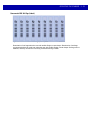
Table 2-4 RS-232 Host Parameters
Parameter
Page
Number
RS-232 Host Type
Standard RS-232 (default)
2-21
ICL RS-232
2-22
Wincor-Nixdorf RS-232 Mode A
2-23
Wincor-Nixdorf RS-232 Mode B
2-24
Olivetti ORS4500
2-25
Omron
2-26
OPOS/JPOS
2-27
Fujitsu RS-232
2-28
CUTE
2-29
NCR Variant
2-30
Datalogic Variant
2-31
RS-232 Device Port Configuration
AUX 1 Sensormatic and AUX 2 RS-232 Scanner (default)
2-33
Third Party Scale
Disable Third Party Scale (default - Disable)
2-38
Third Party Scale LED Pin (default - Active High)
2-40
Third Party Scale Zero Pin (default - Active High)
2-42
2 - 16 MP6000 INTEGRATOR GUIDE
RS-232 Host Parameters
Various RS-232 hosts use their own parameter default settings. Selecting standard, ICL, Fujitsu,
Wincor-Nixdorf Mode A, Wincor-Nixdorf Mode B, OPOS/JPOS, Olivetti, Omron, Common Use Terminal
Equipment (CUTE-LP/LG bar code readers), NCR, or Datalogic sets the defaults listed in Table 2-5 and Table
2-6.
NOTE
Table 2-5
All items listed in Table 2-5 and Table 2-6 are for scanner only connections, except for NCR which can
support scanner and scale.
Terminal Specific RS-232
Parameter
ICL
Fujitsu
Wincor-Nixdorf
Mode A
Wincor-Nixdorf Mode
B/OPOS/JPOS
Baud Rate
9600
9600
9600
9600
Parity
Even
None
Odd
Odd
Stop Bit Select
One
One
One
One
ASCII Format
8-Bit
8-Bit
8-Bit
8-Bit
Hardware Handshaking
RTS/CTS Option 3
None
RTS/CTS Option 3
RTS/CTS Option 3
Software Handshaking
None
None
None
None
Serial Response Timeout
9.9 Sec.
2 Sec.
None
None
RTS Line State
High
Low
Low
Low = No data to send
Beep On <BEL>
Disable
Disable
Disable
Disable
Transmit Code ID
Yes
Yes
Yes
Yes
Data Transmission Format
Data/Suffix
Data/Suffix
Data/Suffix
Data/Suffix
Prefix
None
None
None
None
Suffix
CR (1013)
CR (1013)
CR (1013)
CR (1013)
In the Nixdorf Mode B, if CTS is low, scanning is disabled. When CTS is high, scanning is enabled.
If you scan Nixdorf Mode B without connecting the digital scanner to the proper host, it may appear
unable to scan. If this happens, scan a different RS-232 host type within 5 seconds of cycling power to the
digital scanner.
HOST INTERFACES AND CABLE PINOUTS 2 - 17
RS-232 Host Parameters (continued)
Table 2-6
Terminal Specific RS-232
Parameter
Olivetti
Omron
CUTE
NCR
(Single
Cable
Scale)
Datalogic
Baud Rate
9600
9600
9600
9600
9600
Parity
Even
None
Even
Odd
Odd
Stop Bit Select
One
One
One
One
One
ASCII Format
7-Bit
8-Bit
7-Bit
7-Bit
7-Bit
Hardware Handshaking
None
None
None
None
None
Software Handshaking
ACK/NAK
None
None
None
None
Serial Response Timeout
9.9 Sec.
9.9 Sec.
9.9 Sec.
9.9 Sec.
9.9 Sec.
RTS Line State
Low
High
High
High
High
Beep On <BEL>
Disable
Disable
Disable
Disable
Enable
Transmit Code ID
Yes
Yes
Yes
Yes
Yes
Data Transmission Format
Prefix/Data/Suffix
Data/Suffix
Prefix/Data/
Suffix
Prefix/
Suffix *
Data/Suffix
Prefix
STX (1002)
None
STX (1002)
STX *
None
Suffix
ETX (1003)
CR (1013)
CR (1013) ETX
(1003)
ETX *
CR (1013)
The CUTE host disables all parameter scanning, including Set Defaults. If you inadvertently select CUTE,
scan Enable Parameter Bar Code Scanning (located in the MP6000 Bar Code Programming Guide) then
change the host selection.
2 - 18 MP6000 INTEGRATOR GUIDE
RS-232 Host Parameters (continued)
Selecting ICL, Fujitsu, Wincor-Nixdorf Mode A, Wincor-Nixdorf Mode B, OPOS/JPOS, Olivetti, Omron,
Common Use Terminal Equipment (CUTE-LP/LG bar code readers), NCR, or Datalogic enables the
transmission of code ID characters listed in Table 2-7 and Table 2-8. These code ID characters are not
programmable and are separate from the Transmit Code ID feature. Do not enable the Transmit Code ID
feature for these terminals.
Table 2-7
Terminal Specific Code ID Characters
Code Type
ICL
Fujitsu
Wincor-Nixdorf
Mode B/
OPOS/JPOS
Wincor-Nixdorf
Mode A
UPC-A
A
A
A
A
UPC-E
E
E
C
C
EAN-8/JAN-8
FF
FF
B
B
EAN-13/JAN-13
F
F
A
A
Bookland EAN
F
F
A
A
Code 39
C <len>
None
M
M
Code 39 Full ASCII
None
None
M
M
Trioptic
None
None
None
None
Code 32
None
None
None
None
Codabar
N <len>
None
N
N
Code 128
L <len>
None
K
K
GS1-128
L <len>
None
P
P
Code 93
None
None
L
L
I 2 of 5
I <len>
None
I
I
D 2 of 5
H <len>
None
H
H
MSI
None
None
O
O
IATA
H<len>
None
H
H
GS1 Databar Variants
None
None
E
E
PDF417
None
None
Q
Q
MicroPDF417
None
None
S
S
Data Matrix
None
None
R
R
QR Codes
None
None
U
U
Aztec/Aztec Rune
None
None
V
V
* 2D bar codes are not supported.
HOST INTERFACES AND CABLE PINOUTS 2 - 19
Table 2-8
Terminal Specific Code ID Characters
Code Type
Olivetti
Omron
CUTE
NCR
Datalogic
UPC-A
A
A
A
A
A
UPC-E
C
E
None
E
E
EAN-8/JAN-8
B
FF
None
FF
FF
EAN-13/JAN-13
A
F
A
F
F
Bookland EAN
A
F
None
None
None
Code 39
M <len>
C <len>
3
B1
*
Code 39 Full ASCII
None
None
3
None
None
Trioptic
None
None
None
None
$T
Code 32
None
None
None
None
AE
Codabar
N <len>
N <len>
None
None
%
Code 128
K <len>
L <len>
5
B3
#
GS1-128
P <len>
L <len>
5
None
None
Code 93
L <len>
None
None
None
&
I 2 of 5
I <len>
I <len>
1
B2
i
D 2 of 5
H <len>
H <len>
2
None
None
MSI
O <len>
None
None
None
@
IATA
H<len>
H<len>
2
None
IA
GS1 Databar Variants
None
None
None
]e0
GS1 Databar - R4
GS1 Databar Limited - RL
GS1 Databar Expanded - RX
PDF417
None
None
6
n/a*
P
MicroPDF417
None
None
6
n/a*
mP
Data Matrix
None
None
4
n/a*
Dm
QR Codes
None
None
7
n/a*
QR
Aztec/Aztec Rune
None
None
8
n/a*
Az
* 2D bar codes are not supported with NCR.
2 - 20 MP6000 INTEGRATOR GUIDE
RS-232 Host Types
To select an RS-232 host interface, scan one of the following bar codes.
NOTES 1. Scanning Standard RS-232 activates the RS-232 driver, but does not change port settings (e.g., parity,
data bits, handshaking). Selecting another RS-232 host type bar code changes these settings.
2. The CUTE host disables all parameter scanning, including Set Defaults. If you inadvertently select
CUTE, scan Enable Parameter Bar Code Scanning (located in the MP6000 Bar Code Programming
Guide) then change the host selection.
Options:
• Standard RS-232 (default)
• ICL RS-232
• Wincor-Nixdorf RS-232 Mode A
• Wincor-Nixdorf RS-232 Mode B
• Olivetti ORS4500
• Omron
• OPOS/JPOS
• Fujitsu RS-232
• CUTE
• NCR Variant
• Datalogic Variant.
HOST INTERFACES AND CABLE PINOUTS 2 - 21
RS-232 Host Types (continued)
*Standard RS-232
2 - 22 MP6000 INTEGRATOR GUIDE
RS-232 Host Types (continued)
ICL RS-232
HOST INTERFACES AND CABLE PINOUTS 2 - 23
RS-232 Host Types (continued)
Wincor-Nixdorf RS-232 Mode A
2 - 24 MP6000 INTEGRATOR GUIDE
RS-232 Host Types (continued)
Wincor-Nixdorf RS-232 Mode B
HOST INTERFACES AND CABLE PINOUTS 2 - 25
RS-232 Host Types (continued)
Olivetti ORS4500
2 - 26 MP6000 INTEGRATOR GUIDE
RS-232 Host Types (continued)
Omron
HOST INTERFACES AND CABLE PINOUTS 2 - 27
RS-232 Host Types (continued)
OPOS/JPOS
2 - 28 MP6000 INTEGRATOR GUIDE
RS-232 Host Types (continued)
Fujitsu RS-232
HOST INTERFACES AND CABLE PINOUTS 2 - 29
RS-232 Host Types (continued)
CUTE 2
2 - 30 MP6000 INTEGRATOR GUIDE
RS-232 Host Types (continued)
RS-232 Host -NCR Variant
Scan the bar code below to enable the NCR variant of the RS-232 host.
IMPORTANT There are several parameter options available with the NCR variant for RS-232. Refer to the
MP6000 Bar Code Programming Guide, p/n 72E-172633-xx to manage the following NCR
related parameters:
•
•
•
•
•
NCR Use Prefix
NCR Prefix
NCR Suffix
NCR Use BCC
NCR Interface.
NCR Variant
HOST INTERFACES AND CABLE PINOUTS 2 - 31
RS-232 Host Types (continued)
RS-232 Host -Datalogic Variant
Scan the bar code below to enable the Datalogic variant of the RS-232 host.
Datalogic Variant
2 - 32 MP6000 INTEGRATOR GUIDE
RS-232 Device Port Configuration
Parameter # 1246
This option allows the user to select which devices to attach to the MP6000, and to which port they are
attached. Scan the appropriate bar codes that follow to select the proper configuration. The available
configurations are:
• 0 = AUX 1 Sensormatic, and AUX 2 RS-232 Scanner (default)
• 1 = AUX 1 Dual Cable Scale, and AUX 2 RS-232 Scanner
• 2 = AUX 1 Sensormatic, and AUX 2 Dual Cable Scale
• 4 = AUX 1 Third Party Scale, AUX 2 Sensormatic.
For Motorola hand-held scanners, configure the auxiliary scanner for a standard RS-232 interface with a Baud
Rate of 9600, 8 Data Bits, 1 Stop Bit, and No Parity. Refer to the Auxiliary Scanner Parameters section in the
MP6000 Bar Code Programming Guide, p/n 72E-172633-xx. for alternate settings.
Changes to this parameter do not take effect until the next power cycle (power cycling does not apply to
123Scan2). For that reason always remember to perform one of the functions below after scanning a device
port parameter.
• Cycle power to the scanner (disconnect, and re-connect scanner cable).
or
• Use the MP6000 Reset button (button combination to reboot the MP6000).
When selecting any of the device port configuration options, ensure the devices connected to the MP6000
correctly match the devices defined for the option. For example, if option 1 is scanned, only a dual cable scale
should be connected to the AUX 1 port, and an RS-232 scanner should be connected to the AUX 2 port.
Turning on the MP6000 with connected devices that do not match the option can result in communication
failures. To ensure successful operation the proper sequence for setting this option is as follows.
1.
Power off the MP6000 (disconnect the power cable).
2.
Disconnect all RS-232 devices (RS-232 scanner, Sensormatic, and/or dual cable scale).
3.
Power on the MP6000(reconnect the power cable).
4.
Scan the appropriate bar code option that matches the intended configuration.
5.
Power off the MP6000.
6.
Connect the appropriate devices.
7.
Power on the MP6000.
HOST INTERFACES AND CABLE PINOUTS 2 - 33
RS-232 Device Port Configuration (continued)
*AUX 1 Sensormatic and AUX 2 RS-232 Scanner
(00h)
2 - 34 MP6000 INTEGRATOR GUIDE
RS-232 Device Port Configuration (continued)
AUX 1 Dual Cable Scale and AUX 2 RS-232 Scanner
(01h)
HOST INTERFACES AND CABLE PINOUTS 2 - 35
RS-232 Device Port Configuration (continued)
AUX 1 Sensormatic and AUX 2 Dual Cable Scale
(02h)
2 - 36 MP6000 INTEGRATOR GUIDE
RS-232 Device Port Configuration (continued)
AUX 1 Third Party Scale, AUX 2 Sensormatic
(04h)
HOST INTERFACES AND CABLE PINOUTS 2 - 37
Third Party Scale Parameters
Third Party Scale
Parameter # 1294
Enable or disable Third Party Scale functionality. When disabled Third Party Scale LED Pin (parameter #
1295) and Third Party Scale Zero Pin (parameter # 1296) are ignored/overridden. (Also see Price
Computational Scale Interface Circuit Drawing on page 2-13.)
Options:
• Enable Third Party Scale
• *Disable Third Party Scale.
Enable Third Party Scale
(1)
2 - 38 MP6000 INTEGRATOR GUIDE
Third Party Scale (continued)
* Disable Third Party Scale
(0)
HOST INTERFACES AND CABLE PINOUTS 2 - 39
Third Party Scale LED Pin
Parameter # 1295
This parameter defines the polarity of the LED/Tare input pin that illuminates the scale LED. This parameter
has no effect if Third Party Scale (parameter # 1294) is disabled.
Options:
• Active Low
• *Active High.
Active Low
(0)
2 - 40 MP6000 INTEGRATOR GUIDE
Third Party Scale LED Pin (continued)
*Active High
(1)
HOST INTERFACES AND CABLE PINOUTS 2 - 41
Third Party Scale Zero Pin
Parameter # 1296
This parameter defines the polarity of the zero output pin when the Scale Zero button is pressed. This
parameter has no effect if Third Party Scale (parameter # 1294) is disabled.
Options:
• Active Low
• *Active High.
Active Low
(0)
2 - 42 MP6000 INTEGRATOR GUIDE
Third Party Scale Zero Pin (continued)
*Active High
(1)
HOST INTERFACES AND CABLE PINOUTS 2 - 43
Connecting an IBM RS-485 Interface
Connect the MP6000 directly to the host interface.
POS
12V
DC
Figure 2-4 IBM RS-485 Connections
To set up the MP6000:
1.
Attach the modular connector of the IBM RS-485 interface cable to the POS interface port on the MP6000.
2.
Connect the other end of the IBM RS-485 interface cable to the appropriate port on the host (typically Port
9). The unit should power up immediately upon connection. If not, wait for unit to power up.
NOTE
Older POS systems, and/or some retailers will require use of the external power supply
PWRS-14000-148R.
3.
Select the port address by scanning the appropriate bar code (refer to MP6000 Bar Code Programming
Guide, p/n 72E-172633-xx.).
4.
If a scale is present in the unit, scan the appropriate scale port address (IBM Scale Port Addresses on
page 2-49).
5.
To modify any other parameter options, scan the appropriate bar codes in the MP6000 Bar Code
Programming Guide, p/n 72E-172633-xx.
NOTE
6.
The only required configurations are the port addresses (IBM RS-485 port address, and a scale port
address if the model has a scale), and type directives (see Step 6). The IBM system typically
controls other MP6000 parameters.
To prevent the IBM POS from configuring the MP6000, refer to the MP6000 Bar Code Programming Guide
for information about RS-485 and IBM USB configuration, beep, scale, and type directives.
2 - 44 MP6000 INTEGRATOR GUIDE
IBM RS-485 Host Parameters
IMPORTANT This chapter includes port address parameters only. For additional user preferences (including IBM
Directives, refer to the MP6000 Bar Code Programming Guide (p/n 72E-172633-xx).
To select the IBM RS-485 port used, scan one of the bar codes listed in Table 2-9..
NOTE
1. Scanning one of these bar codes enables the RS-485 interface on the MP6000.
2. The port numbers in Table 2-9 are no longer physical ports on the IBM POS.
NOTE
This guide includes limited parameter bar codes. For ALL MP6000 programming bar codes, refer to the
MP6000 Bar Code Programming Guide (p/n 72E-172633-xx).
Table 2-9 IBM RS-485 Port Parameters
Parameter
Page
Number
IBM Port Addresses
None Selected (default)
2-45
Hand-Held Scanner Emulation (Port 9B)
2-46
Non-IBM Scanner Emulation (Port 5B)
2-47
Table Top Scanner Emulation (Port 17)
2-48
IBM Scale Port Addresses
None Selected (default)
2-49
Port 6A
2-50
Port 6B
2-51
Port 6E
2-52
HOST INTERFACES AND CABLE PINOUTS 2 - 45
IBM Port Addresses
*None Selected
2 - 46 MP6000 INTEGRATOR GUIDE
IBM Port Addresses (continued)
Hand-held Scanner Emulation (Port 9B)
HOST INTERFACES AND CABLE PINOUTS 2 - 47
IBM Port Addresses (continued)
Non-IBM Scanner Emulation (Port 5B)
2 - 48 MP6000 INTEGRATOR GUIDE
IBM Port Addresses (continued)
Tabletop Scanner Emulation (Port 17)
HOST INTERFACES AND CABLE PINOUTS 2 - 49
IBM Scale Port Addresses
The scale port address must be configured for the scale to operate on the IBM RS-485 bus. The default is
None Selected.
*None Selected
2 - 50 MP6000 INTEGRATOR GUIDE
IBM Scale Port Addresses (continued)
Port 6A
HOST INTERFACES AND CABLE PINOUTS 2 - 51
IBM Scale Port Addresses (continued)
Port 6B
2 - 52 MP6000 INTEGRATOR GUIDE
IBM Scale Port Addresses (continued)
Port 6E
HOST INTERFACES AND CABLE PINOUTS 2 - 53
Connector Pins
RS-232 AUX 1
Table 2-10 RJ-45
Pin #
Signal/Name
Direction
Description
1
N/C
N/A
No Connection
2
5V
Out
RS-232 scanner 5VDC Supply*
3
GND
N/A
Signal Ground
4
TXD
Out
Serial TXD (±5.4V)
5
RXD
In
Serial RXD (±5.4V)
6
RTS
Out
Serial RTS (±5.4V)
7
CTS
In
Serial CTS (±5.4V)
8
(GEN II
only)
Scale LED
In
Indicates price computational scale has returned to
zero - reflected in UI Scale Status LED (if enabled). I/O
signals are 5V TTL.
9
(GEN II
only)
Scale Zero
Out
Zeros price computational scale when the Zero UI
button is pressed (if enabled). I/O signals are 5V TTL.
10
(GEN II
only)
12V/150mA
Out
Power output for price computational scale.
Scale Display Port
Table 2-11 RJ-11, Scale Display
Pin #
Signal/Name
Direction
Description
1
DEBUG_TXD
Out
Debug serial TX
2
5V
Out
Auxiliary 5V output *
3
TXD
Out
Scale Display serial TX (3.3V TTL)
4
RXD
In
Scale Display serial RX (3.3V TTL)
5
GND
N/A
Signal ground
6
DEBUG_RXD
In
Debug serial RX
* The total combined current for the USB and RS-232 peripheral ports should be less than
750mA total auxiliary current. Each individual port should not exceed 500mA.
2 - 54 MP6000 INTEGRATOR GUIDE
RS-232 AUX 2
Table 2-12 RJ-45
Pin #
Signal/Name
Direction
Description
1
N/C
N/A
No connection
2
5V
Out
RS-232 scanner 5V supply *
3
GND
N/A
Signal ground
4
TXD
Out
Serial TXD (±5.4V)
5
RXD
In
Serial RXD (±5.4V)
6
RTS
Out
Serial RTS (±5.4V)
7
CTS
In
Serial CTS (±5.4V)
8
N/C
N/A
No connection
9
N/C
N/A
No connection
10
12V/150mA
Out
Output for auxiliary device.
NOTE
150mA maximum available
between both AUX 1 and AUX 2.
* The total combined current for the USB and RS-232 peripheral ports should be less than
750mA total auxiliary current. Each individual port should not exceed 500mA.
Checkpoint Interlock
Table 2-13 EAS Interlock Connector
Pin #
Signal/Name
Direction
Description
1
Interlock
Out
Checkpoint EAS Interlock (5V 4mA PNP collector out)
2
GND
N/A
Signal ground
AUX A-B (Stacked USB)
Table 2-14 Stacked USB Port
Pin #
Signal/Name
Direction
Description
1
5V
Out
USB 5V output *
2
D-
Bidirectional
USB D-
3
D+
Bidirectional
USB D+
4
GND
N/A
Signal ground
* The total combined current for the USB and RS-232 peripheral ports should be less than 750mA
total auxiliary current. Each individual port should not exceed 500mA.
HOST INTERFACES AND CABLE PINOUTS 2 - 55
NOTE
An additional USB port is available in the front under the platter. All USB ports can be used for
the USB staging flash drive. See Table 1-3 on page 1-14 and USB Staging Flash Drive on page
5-11 for additional information.
POS
Table 2-15 RJ-45, Primary POS
Pin #
Signal/Name
Direction
Description
1
DETECT
Out
USB cable detect output
2
5V
In
USB cable 5V detect input
3
GND
N/A
Signal ground
4
TXD/IBM-A
Bidirectional
Multiplexed serial TXD/IBM-A
5
RXD/D+
Bidirectional
Multiplexed serial RXD/USB D+
6
RTS/IBM-B
Bidirectional
Multiplexed serial RTS/IBM-B
7
CTS/USB D-
Bidirectional
Multiplexed serial CTS/USB D
8
DOWNLOAD
In
POS download
9
N/C
N/A
10
12V
In
Terminal 12VDC to MP6000
(Power From Terminal) *
* Terminal systems vary in power capabilities. Ensure your system power supply is capable
of the MP6000 configuration power requirements. For terminals unable to support P.O.T., a
12V DC barrel jack is available for external power.
12V DC
Table 2-16 12V DC Jack, 2.5mm
Pin #
Signal/Name
Direction
Description
1
EXT 12V
In
Center pin: 12VDC (primary power)
2
GND
N/A
Barrel: signal ground
2 - 56 MP6000 INTEGRATOR GUIDE
CHAPTER 3 SITE PREPARATION AND
INSTALLATION
Overview
The MP6000 was designed to drop into an existing bioptic checkstand cutout with no modifications. The unit is
available in three industry standard sizes (for more detailed information, see Appendix B, TECHNICAL
SPECIFICATIONS):
• Short - no scale available
Length:
Width:
13.9 in. +0/-.05 in. (353.0 mm)
11.5 in. +0/-.05 in. (292.0 mm)
• Medium - with or without scale
Length:
Width:
15.7 in. +0/-.05 in. (399.0 mm)
11.5 in. +0/-.05 in. (292.0 mm)
• Long - with or without scale
Length:
Width:
20.0 in. +0/-.05 in. (508.0 mm)
11.5 in. +0/-.05 in. (292.0 mm)
3-2
MP6000 INTEGRATOR GUIDE
Site Preparation
IMPORTANT This guide does not encompass all factors related to worker safety and check stand design. It does
offer a list of considerations which may be helpful in ensuring greater safety and productivity.
Ventilation and Spacing Requirements
The scanner/scale housing was designed to provide adequate space for ventilation and drainage for spills.
Figure 3-1 shows the drainage holes, under the platter, for possible spills that may occur when
scanning/weighing items.
Checkstand ventilation may be required to ensure the MP6000 temperature limits are not exceeded. If forced
air ventilation is used, it must not pass through the MP6000 as this can produce an unstable weighing
environment. The ambient air temperature inside the checkstand, adjacent to the device, must not exceed
104°F (40°C).
MP6000 Top View
(Drainage/Ventilation Holes on Both Sides)
MP6000 Side View
(Drainage/Ventilation Holes on Both Sides)
Figure 3-1 Drainage/Ventilation Holes
Service Access Requirements
The MP6000 was engineered to allow performance of all routine service and maintenance (including scale
zeroing, and calibration) without removing the scanner from the counter.
Service must be performed by a Motorola Certified Repair Provider who has completed the Service Repair
Training course, and (if applicable) the Scale Calibration Training course. For MP6200 and MP6500
scanner/scales, depending on the region of installation, a certified Weights & Measures technician is required
to place the device in trade before using, and after certain repairs.
SITE PREPARATION AND INSTALLATION
3-3
Electrical Power Considerations
The MP6000 may be powered from two different sources:
• POS Equipment
• IBM register with powered Port 9B interface (using p/n CBA-M51-S16PAR accessory cable)
• NCR POS with powered RS-232 interface (using p/n CBA-R55-S16PAR accessory cable)
• Any register with powered USB interface - 12V only (using p/n CBA-U52-S16PAR accessory cable)
• AC/DC power cube (using p/n PWRS-140000-148R) with IEC style modular line cord.
1.2 in.(+/- 0.01)
62.0 mm (+/- 0.25)
2.4 in.(+/- 0.01)
62.0 mm (+/- 0.25)
4.3 in.(+/- 0.01)
110.0 mm (+/- 0.25)
Figure 3-2 Power Supply
If using the AC/DC accessory power supply, a 115V/230V outlet must be available in the checkstand near the
scanner.
Grounding
All POS equipment should be properly grounded, and only a three prong IEC style line cord should be used
with the AC/DC accessory power supply.
If you are unsure how to verify proper ground of equipment in the checkstand ask a qualified electrician to
review the equipment installation.
NOTE
In an effort to eliminate a possible safety hazard all metal parts of a metal checkstand must be electrically
grounded.
3-4
MP6000 INTEGRATOR GUIDE
Checkstand Preparation
If the MP6000 is not replacing an old bioptic device, and you are installing for the first time into a new
checkstand, verify that the area allows for proper cabling, and an AC/DC power supply. Mounting may require
installation of support(s), leveling screws, and peripheral devices. See Counter Cutout on page 3-5 for more
details about the location and preparation of the opening.
Figure 3-3 Preparing the Checkstand
IMPORTANT The long (20.0 in./50.2 cm) versions are not available with leveling screws. The checkstand should
provide for two leveling screws under the front and rear of the MP6000. The medium (15.7 in./39.9
cm) and short (13.9 in./35.3 cm) MP6000 models have available accessory kits for standard and
long leveling screws.
Liquid Spills and Moisture
Select a checkstand design which allows fluids to flow through, and directs liquids and moisture build up away
from any electronic equipment or storage areas. Should a liquid spill occur, ensure that moisture can flow
through the checkstand without pooling. The power supply should be away from any area where spills may
occur.
Vertical Clearance
For all configurations of the MP6000, the maximum height above the platter is 5.1 in.; the maximum depth
below the platter is 4.08 in.
Tools
No tools are required to install a MP6000 without a scale, or a Checkpoint antenna. The following tools are
required to mount the Scale Display:
• Ruler (or similar measuring device)
• Pencil (or similar measuring device)
• Drill
• 2.4 mm (3/32 in.) diameter drill bit (to make screw holes where display is to be mounted)
• 19 mm (3/4 in.) diameter drill bit (to make cable pass through hole where display is to be mounted)
• #2 Phillips screwdriver.
If the optional leveling screws are used on a small or medium MP6000, a Phillips or flat blade screwdriver is
needed.
SITE PREPARATION AND INSTALLATION
3-5
Counter Cutout
There are three different MP6000 models: long, medium, and short. Prior to cutting the counter opening,
ensure you have the dimensions for the scanner/scale being installed (see Figure 3-29, Figure 3-33, and
Figure 3-37). The counter cutout size should reflect the model (also see page 3-30 for installation information).
Ergonomics
Ensure the installation is designed for maximum comfort, efficiency, safety, and ease of use. Allow items to be
directed within easy reach, and a scanning area requiring no lifting or special orientation of items.
3-6
MP6000 INTEGRATOR GUIDE
Installing Components
The MP6000 can be installed with or without the following options:
• Scale and Scale Display (depending on Weights and Measure regulatory jurisdictions, a Scale Display
may be required for units with a scale)
• Checkpoint EAS antenna
• Sensormatic EAS coil antennae and RS-232 cabling
• CSS
• AUX hand-held scanners.
Quick Reference Installation Steps
1.
Remove the existing bioptic scanner, and accessories (page 3-7).
2.
Unpack the MP6000, and accessories (page 3-7).
3.
Assemble the dual head Scale Display, if applicable (page 3-9).
NOTE
This only applies when adding a second display head to a single Scale Display.
4.
Install the Scale Display, if applicable (page 3-12).
5.
Connect the cables (page 3-15).
6.
Install CSS, if applicable (page 3-16).
7.
Install the MP6000/scale in the checkstand (page 3-24).
8.
Power up the MP6000 (page 3-32).
9.
Lower and level the MP6000 in the checkstand (page 3-30).
10. Calibrate the scale, if applicable (see Chapter 4, SCALE CALIBRATION (MODELS WITH A SCALE
ONLY).
11. Install Sensormatic coil, if applicable (page 3-33).
12. Install Checkpoint antenna, if applicable (page 3-35).
13. Install the MP6000 trim kit, if applicable (page 3-36).
SITE PREPARATION AND INSTALLATION
3-7
Remove Existing Bioptic Scanner and Accessories
If you are replacing existing equipment, follow these step to remove the old unit:
1.
Ensure the POS is logged off, and the drawer was cleared by the store personnel. This varies by location.
Some IT Departments may require the POS to be completely shut down.
2.
Unplug the current bioptic scanner from its power supply.
3.
Prior to removing cables, make a note of the current cable runs.
4.
Remove all cables connected to the bioptic scanner. Do not cut cables if you are using, or selling the old
equipment.
5.
If applicable, unplug the current hand-held device from its power supply, and disconnect it from the current
bioptic scanner/host.
6.
7.
8.
a.
If reusing the hand-held device, leave its cable runs intact.
b.
If the hand-held device was attached to the bioptic scanner with an RS-232 cable, a new cable and a
new hand-held device configuration is required.
If a Sensormatic connection is present, there are two cables to be aware of:
a.
The large cable to the coils/antennas - disconnect from the current bioptic but leave in place.
b.
The RS-232 cable to the Sensormatic controller communications port - use its run to assist replacing it.
If a Scale Display is present:
a.
Make a note of how the current display was mounted and determine if the current placement can
accommodate the new Scale Display. Adjustments to the layout, and cable run may be required.
b.
Unplug the old Scale Display power.
c.
Remove it from the checkstand.
d.
Remove its cables.
e.
Remove the Scale Display.
Remove the existing bioptic scanner.
Unpacking MP6000 Equipment
To unpack equipment:
1.
Remove all components from their packaging, and check that all parts are present. Each box includes the
material listed in Table 3-1. Each of the items listed is contained in separate packaging within the box and
is recognizable as a discrete item. Power cables, host to scanner communications cables, leveling screws,
and trim filler kit are all sold separately in kits.
Table 3-1 MP6000 Box Contents
Description
Part Number
MP6000 w/o Platter
MP6xx0-xx000M010xx
Platter
22-159817-xxx
Checkpoint Antenna
10-162248-xx
Regulatory Guide
72-171321-xx
NOTE
An optional Scale Display, p/n MX201-SR00004ZZWR, is available separately for scale models only.
3-8
MP6000 INTEGRATOR GUIDE
2.
For added protection during shipment, the MP6000 platter is covered with a tight fitting layer of plastic as
shown in Figure 3-4. This plastic layer must be removed before placing the unit into service. (In the case of
a scale model, just before scale calibration; and, in case of a non-scale model, as the final step of
installation)
Figure 3-4 Platter Protector
CAUTION
3.
Do not use a sharp object to remove the protector. Doing so can damage the platter.
Keep the packing (it is the approved shipping container, and should be used if the MP6000 needs to be
returned for servicing), or dispose of the packing in an environmentally sensitive manner.
Pre-Installation Notes
• If a Scale Display is included, it is recommended to mount it in an appropriate location, preferably where
the old display was mounted. The cable should be routed through the checkstand.
• If the unit includes a scale, scale calibration is required.
• If the unit includes EAS Sensormatic:
• its coils require installation
• the large Sensormatic cable should be threaded from the controller box to the coils
• The Sensormatic RS-232 cable should be connected to the unit.
• If EAS Checkpoint is required, unravel the Checkpoint antenna and ensure a Checkpoint representative
connects the device to the controller.
• If EAS Checkpoint with interlock is used, connect the interlock cable to the MP6000.
• All accessories (hand-held scanner, CSS, etc.) require connections.
SITE PREPARATION AND INSTALLATION
3-9
Assemble the Dual Head Scale Display
NOTE
This only applies when adding a second display head to a single display.
Required Tools
• Phillips head screw driver.
To convert a single display to a double display:
1.
The second Scale Display head ships with a cable (already fitted), pole grip, two M3 x 12 self tapping
Phillips screws, and a set of four display overlays.
Pole Grip
Figure 3-5 Second Scale Display
2.
Remove the adhesive backing of the required overlay, and carefully secure it in place on the front face of
the new display.
NOTE
3.
The new overlay must contain exactly the same information as the existing display.
Remove the four securing screws from the rear of the existing display before removing the front of the
existing display, complete with LCD and PCB.
Figure 3-6 Dismantling Existing Display
3 - 10 MP6000 INTEGRATOR GUIDE
4.
Remove the circular cap from the existing display and either discard, or keep it as a spare part.
Figure 3-7 Removing Circular Cap
5.
Connect the cable from the new display to the RJ-11 port marked “To Slave” on the PCB in the existing
(single head) display.
6.
Place the short pole extension of the new display into the vacant slot in the rear cover of the existing
display.
Figure 3-8 Short Pole Extension
NOTE
There is a rotation limiting tab on the top and bottom surfaces of the pole extension (see Figure
3-9). These need to be fitted one side or the other of the mating projection in the rear cover. If not,
there may be difficulty replacing the existing front cover.
Figure 3-9 Rotation Limiting Tab
SITE PREPARATION AND INSTALLATION 3 - 11
7.
Secure in place using the pole grip and two M3 x 12 self tapping screws supplied. These are Phillips screw
heads.
Figure 3-10 Secure in Place
8.
Replace the case back of the existing (original single-head) display using the four M3 x 18 self tapping
screws (removed earlier).
3 - 12 MP6000 INTEGRATOR GUIDE
Install the Scale Display
When installing the optional Scale Display, consider both the cashier and customer’s viewing angle. Both must
see the weight value displayed.
2.3 in
58.0 mm
o
290
3.0 in
75.0 mm
3.1in
77.5 mm
6.1 in
155.0 mm
10.7 in
272.0 mm
0.6 in
15.0 mm
4.5 in/115.0 mm
Figure 3-11 Single Scale Display - Dimensions; Display Rotates Independently (Approximately 290 o)
SITE PREPARATION AND INSTALLATION 3 - 13
o
290
10.5 in
267.0 mm
15.5 in
394.0 mm
2.8 in
70.0 mm
3.0 in
75.0 mm
3.1 in
77.5 mm
6.1 in
155.0 mm
2.3
2.3 in
in
57.5 mm
Figure 3-12 Dual Scale Display - Dimensions; Display Rotates Independently (Approximately 290 o)
3 - 14 MP6000 INTEGRATOR GUIDE
4.53 in. (115 mm)
3.62 in. (92 mm)
1.57 in.
(40 mm)
0.75 in.
(19 mm)
Figure 3-13 Scale Display - Base Install Template
NOTE
When printing this template ensure the Page Scaling option is set to None, or a setting that allows
printing the actual size.
Getting Started
For an existing Scale Display from an old scanner:
• Unscrew the unit, disconnect its cable from scanner, then remove the unit and cables.
• In same location, (or in a new location as specified by the retailer and/or local weights and measures law)
replace with the Motorola Scale Display.
For a new installation:
• Identify the location to install the Scale Display. Identify the location to place the Scale Display based on
counter design and viewing angle. Place the unit where it cannot impede access to scanned items being
swept over the MP6000, payment terminals, printer validation and paper roll slots, access to replace
consumables (rolls) etc.
NOTE
BOTH cashier and customer need to see the weight value displayed.
• Drill the required holes where the display is to be mounted (see the template, Figure 3-13).
a.
The 19 mm (3/4 in.) diameter hole is optional, to be used as a through hole for the cable pass-through.
NOTE
b.
The cable can also be routed on top of the counter via the notch in the base of the display. See the
template for hole spacing.
The other two holes are pilot holes for the mounting screws and should be made to a diameter of 2.4
mm (3/32 in.) and a depth of 25 mm (.98 in.). See the template for hole spacing.
SITE PREPARATION AND INSTALLATION 3 - 15
Installing
1.
Unpack the new Scale Display from its packaging.
2.
Place the proper Scale Display faceplate on the display.
Fit the correct label on the Scale Display window. Select an overlay to ensure the proper weight units
(kg or lb) that are required and parameters EXACTLY match the scale parameters printed on the scale
Weights and Measures label. Depending on the unit, and the country location, labels vary. You MUST
match the label to the type of MP6000 scale you are installing. (Labels, and instructions for their use,
are packaged with the Scale Display.)
a.
•
•
•
•
•
b.
3.
kg single interval
lb single interval
kg dual interval
lb dual interval
other models as released over time, e.g. Portuguese for Brazil, etc.
Remove adhesive backing and carefully secure on the front face of the display.
Route the cable through the 19 mm hole in the countertop, or route the cable out through the notch in the
base of the display.
NOTE
4.
5.
The notch is usually located towards the rear, where it is less visible.
Fasten the Scale Display to the countertop.
a.
Place and align the display over the countertop screw holes.
b.
Place two screws through each screw hole in the base of the display.
c.
Drive both screws into the counter until tight.
d.
Route the cable accordingly and connect the Scale Display cable to port 0.0 Scale Display on the
MP6000 BEFORE powering up the scanner/scale (see Figure 1-3 on page 1-10).
Power on the MP6000. On power up, the Scale Display presents the following test sequence:
a.
Displays 00.000 for 1.5 seconds; then displays 99.999 for 1.5 seconds.
b.
Displays xx.xx0 lb or xx.xxx kg (based on the units selected) in normal operating mode.
Cables and Connections
When routing the power and interface cables for the MP6000:
• Do not route interface cables in close proximity to electrical motors or other sources of electromagnetic
interference.
• Cables can drop directly from their connectors on the scanner, or, alternatively, can be routed along the
scanner's side to the back.
• Connect the power cable to the MP6000 before plugging the AC power cord into the AC outlet.
3 - 16 MP6000 INTEGRATOR GUIDE
Install the Customer Side Scanner (MX101)
The MX101 is an optional modular unit that fits into a modified MP6000 tower and is used for customer
scanning. The unit can be installed on either the left or right side of the MP6000.
Remove all hardware from the packaging. The packaging contains the MX101 scan module and window;
MP6000 modified rear tower; USB cable; and MX101 identification label (Regulatory Guide; instructions to affix
the label on the MP6000; and installation instructions not shown).
Identification
Label
Tower
Scan Module and Window
USB Cable
Figure 3-14 Parts of the MX101
SITE PREPARATION AND INSTALLATION 3 - 17
Installing the MX101 on the Customer’s Right Side (Default) of the Tower Cover
To install the MX101 on the customer’s right side (default) of the MP6000:
1.
Remove the MP6000 tower bezel by squeezing inward on both the left and right sides of the lower part of
the tower bezel, pushing its side snaps to disengage. Slide the tower bezel up and lift out.
Tower Bezel
Squeeze
Inward
Figure 3-15 Removing the MP6000 Tower Bezel
2.
Remove the MP6000 rear tower cover by gently pulling outwards on the tabs on either side; then slide the
tower cover back to remove.
Tab(s)
(on each
side)
Figure 3-16 Removing the MP6000 Tower Cover
3.
Determine the side of the MP6000 to which the MX101 should be installed. The default is the customer’s
right side (the side of the MX101 tower cover already open for the scan module to be inserted).
NOTE
See Installing the MX101 on the Customer’s Left Side of the Tower Cover on page 3-21 to install the scan
module on the customer’s left side of the tower cover.
3 - 18 MP6000 INTEGRATOR GUIDE
4.
Remove the scan window cover from the CSS tower by squeezing the snaps shown below. The snaps are
squeezed from inside the tower cover.
Snaps
Figure 3-17 Removing the Scan Window Cover
5.
Insert the scan module into place facing out of the opening of the CSS tower cover. Ensure the grommets
on the scan module align with the sockets in the tower cover, and push into place.
Scan Module
Grommets (3)
Grommet
Sockets
(3)
CSS Tower
Cover
Figure 3-18 Inserting the Scan Module
Module
Installed
SITE PREPARATION AND INSTALLATION 3 - 19
6.
Snap the scan window cover into place on the tower, over the CSS scan window.
Figure 3-19 Snapping the Scan Window Cover in Place
NOTE
7.
Ensure you hear and feel three distinct snaps: one for each snap mechanism (lower, front, rear), to ensure
a snug fit in the rear tower.
Connect the USB cable to the top USB auxiliary port (recommended) on the MP6000. Route the cable into
the side cable slots as shown.
Side Cable Slots
Top USB Auxiliary Port
Figure 3-20 Connecting the USB Cable
3 - 20 MP6000 INTEGRATOR GUIDE
8.
Route the cable, looping through the right side cable slots as shown in Figure 3-21. (Cable wire should be
tight.)
Cable Slots
Service Loop
Cable Slots
Figure 3-21 Routing the Cable
NOTE
9.
The path through the cable slots is not intuitive. Send the cable towards the left of the tower (as shown)
even though the CSS module is on the right. (Take up all the slack outside the MP6000 chassis so the
CSS cable cannot be pinched by the checkstand.)
Connect the cable to the micro USB port at the bottom of the CSS scan module. Ensure the cable is
clipped into the scan module plastic cable clip directly below the USB port.
Scan Module Cable Clip
Service
Loop
Micro USB Port
Figure 3-22 Connecting the Cable
SITE PREPARATION AND INSTALLATION 3 - 21
10. Slide the CSS tower cover back into place. Ensure the cable service loop folds up into the blank space in
the CSS tower cover, on the opposite side from the scan module. Snaps should click together. When the
tower cover is replaced, the module locks into the grommet compression ribs on the MP6000 inner tower.
Figure 3-23 Replacing the Tower Cover
11. Replace MP6000 tower bezel. Snap down into place.
Figure 3-24 Replacing the MP6000 Tower Bezel
Installing the MX101 on the Customer’s Left Side of the Tower Cover
To install the MX101 on the left side of the MP6000:
3 - 22 MP6000 INTEGRATOR GUIDE
1.
Push out the CSS blank side cover on the left side of the CSS tower cover, and replace the cover into the
opening on the right side of the tower cover.
Figure 3-25 Removing the Side Cover
2.
Repeat steps 1, 2, and 3 from Installing the MX101 on the Customer’s Right Side (Default) of the Tower
Cover on page 3-17.
3.
Insert the scan module into place facing out of the left side opening of the CSS tower cover. Ensure the
grommets on the scan module align with the sockets in the tower cover, and push into place.
4.
Snap the scan window cover into place on the tower, over the scan window. (See page 3-19 for diagrams.)
5.
Connect the USB cable to the top USB port (recommended) on the MP6000 and route the cable through
the side cable slots shown in step 7 on page 3-19.
SITE PREPARATION AND INSTALLATION 3 - 23
6.
Route the cable, looping through the left side cable slots as shown below.
Cable Slots for Left Side
Installation
Scan Module Cable
Clip
Figure 3-26 Routing the Cable
NOTE
The path through the cable slots is not intuitive. Send the cable towards the right of the tower (as shown)
even though the CSS module is on the left. (Take up all the slack outside the MP6000 chassis so the CSS
cable cannot be pinched by the checkstand.)
7.
Connect the cable to the micro USB port on the bottom of the scan module. Ensure the cable is clipped
into the scan module plastic directly below the USB port. (See step 9 on page 3-20 for illustration.)
8.
Slide the CSS tower cover back into place. Ensure the cable service loop folds up into the blank space in
the CSS tower cover, on the opposite side of the scan module. Snaps should click together. When the
tower cover is replaced, the module locks into the grommet compression ribs on the MP6000.
9.
Replace MP6000 tower bezel. Snap down into place.
Affixing the Identification Label
IMPORTANT Before you install the MX101, affix the identification label under the MP6000 platter, as shown in
Figure 3-28. Failure to affix the identification label to the MP6000 voids the MX101 warranty.
Peel the label from its backing.
xxxxxxxxxxx
Figure 3-27 Peel Off Backing
3 - 24 MP6000 INTEGRATOR GUIDE
Affix the label to the indentation under the MP6000 platter.
xxxxxxxxxxx
MP6000 (under platter)
Figure 3-28 Affix Label
Install the MP6000 /Scale
Ensure all components of the MP6000/scale (if applicable) and cables are ready to install (see Unpacking
MP6000 Equipment on page 3-7).
Checkstand Counter Cutouts and MP6000 Dimensions
There are three different sets of dimensions for counter cutouts, based on the MP6000 model being installed.
After cutting the edges should be clean and straight, with all burrs and splinters removed.
The MP6000 is 11.5 in. wide. If replacing a pre-existing scanner in a checkstand that is 12 in. wide, we
recommend a Trim Filler Kit to fill-in the gap in the checkstand (see Trim Kit Installation (If Required) on page
3-36).
The MP6000 is 4 in. deep. If replacing a pre-existing 5 in. deep short or medium scanner, you must use the 1
in. longer leveling screw kit (p/n MX302-SR00004ZZWR). This will bring the platter up to the countertop level.
SITE PREPARATION AND INSTALLATION 3 - 25
Cutout/Dimensions - MP6000 Short
14.03 in. +/- 0.06 in.
356.2 mm +/- 1.5 mm
11.63 in. +/- 0.06 in.
295.3 mm +/- 1.5 mm
Max R 0.25 in.
6.35 mm
2x Cashier Side
Max 4.0 in.
101.6 mm
Max 0.25 in.
6.4 mm
Optional Leveling
Feet Locations
Figure 3-29 MP6000 - Short Unit (No Scale) Counter Cutout
1.75 in. +/- .25 in.
44.6 mm +/- 6.6 mm
1.75 in. +/- .25 in.
44.6 mm +/- 6.6 mm
Support Rails
Figure 3-30 MP6000 - Short Unit (No Scale) Front View Dimensions
IMPORTANT Use the support rails as shown, and not a shelf. If liquid spills it pools on a shelf.
3 - 26 MP6000 INTEGRATOR GUIDE
Cutout/Dimensions - MP6000 Short (continued)
11.50 in.
292.2 mm
13.90 in.
353.1 mm
Figure 3-31 MP6000 - Short Unit (No Scale) Top View Dimensions
14.03 in. +/- 0.06 in.
356.2 mm +/- 1.5 mm
(Counter Opening)
5.1 in.
128.5 mm
4.00 in.
101.6 mm
Optional leveling screw kit
MX301-SR00004ZZWR
Figure 3-32 MP6000 - Short Unit (No Scale) Side View Dimensions
SITE PREPARATION AND INSTALLATION 3 - 27
Cutout/Dimensions - MP6000 Medium
15.83 in. +/- 0.06 in.
402 mm +/- 1.5 mm
11.63 in. +/- 0.06 in.
295.3 mm +/- 1.5 mm
1.75 in. +/- .25 in.
44.6 mm +/- 6.6 mm
Max R0 .25 in.
6.35 mm
2X Cashier Side
Max 4.00 in.
101.6 mm
Max 2.00 in.
50.8 mm
Optional Leveling
Feet Locations
Figure 3-33 MP6000 - Medium Unit Counter Cutout
Support Rails
1.75 in. +/- 0.25 in.
44.5 mm +/- 6.6 mm
1.75 in. +/- 0.25 in.
44.5 mm +/- 6.6 mm
Figure 3-34 MP6000 - Medium Unit Front View Dimensions
IMPORTANT Use the support rails as shown, and not a shelf. If liquid spills it pools on a shelf.
3 - 28 MP6000 INTEGRATOR GUIDE
Cutout/Dimensions - MP6000 Medium (continued)
15.83 in. +/- 0.06 in.
402 mm +/- 1.5 mm
Counter Opening
5.1 in.
128.5 mm
4.00 in.
101.6 mm
Optional leveling screw kit
MX301-SR00004ZZWR or
MX302-SR00004ZZWR
Figure 3-35 MP6000 - Medium Unit Side View Dimensions
11.50 in.
292.2 mm
15.66 in.
397.8 mm
Figure 3-36 MP6000 - Medium Unit Top View Dimensions
SITE PREPARATION AND INSTALLATION 3 - 29
Cutout/Dimensions - MP6000 Long
20.13 in. +/- 0.06 in.
511.2 mm +/- 1.5 mm
Min 0.75 in. - Max 1.65 in.
Min 19.1 mm - Max 42.0 mm
Min 0.75 in. - Max 1.22 in.
Min 19.1 mm - Max 31.0 mm
(Cashier Side)
Typical Checkstand
Leveling Screw Locations
11.63 in. +/- 0.06 in.
295.3 mm +/- 1.5 mm
Max 18.63 in.
473.1 mm
Figure 3-37 MP6000 - Long Unit Counter Cutout
20.13 in. +/- 0.06 in.
511.2 mm +/- 1.5 mm
(Counter Opening)
0.38 in. +/- 0.03 in.
9.5 mm +/- 0.8 mm
0.38 in. +/- 0.03 in.
9.5 mm +/- 0.8 mm
5.1 in.
128.5 mm
(Counter to Top of Unit)
4.00 in.
101.6 mm
Max 18.63 in.
473.1 mm
Figure 3-38 MP6000 - Long Unit Side View Dimensions
NOTE
The countertop, after routing, must have sufficient strength to support the scanner and the loads placed
on top of it. If the countertop is not strong enough, add strengthening supports underneath the countertop
as required
3 - 30 MP6000 INTEGRATOR GUIDE
Cutout/Dimensions - MP6000 Long (continued)
11.50 in.
292.2 mm
20.0 in.
506.9 mm
Figure 3-39 MP6000 - Long Unit Top View Dimensions
To install the MP6000:
1.
Ensure the following items were completed:
a.
Existing scanner and accessories were removed, if applicable. See Remove Existing Bioptic Scanner
and Accessories on page 3-7.
b.
Cables were connected and routed. See Cables and Connections on page 3-15.
c.
The Scale Display was installed, if applicable. See Install the Scale Display on page 3-12.
d.
CSS was installed, if applicable. See Install the Customer Side Scanner (MX101) on page 3-16.
e.
Sensormatic coil, or Checkpoint EAS antenna was installed, if applicable. See Install Sensormatic
Coils on page 3-33, or Install Checkpoint Antenna on page 3-35.
2.
Verify checkstand dimensions shown in Figure 3-29, Figure 3-33, and Figure 3-37, respectively.
3.
Lower scanner in checkstand as follows.
a.
Remove the platter to access the front handle of the device (see Installing/Removing the Long Scale
Platter on page 5-8).
SITE PREPARATION AND INSTALLATION 3 - 31
b.
To grasp the MP6000 to lower it into the checkstand, use the support handle on the back of the tower
cover together with the front part of the scale, or the handle in the front flange area (if installing the long
model). See Figure 3-40 on page 3-31.
GRIP
GRIP
Figure 3-40 Lowering the Medium MP6000 into the Counter
c.
Replace the platter.
d.
Ensure the device is seated properly - see (i) for Long and (ii) for Medium and Short
i.
Long MP6000: The long MP6000 should not rock on the checkstand's adjustable supports
(screws), and the platter must be flush with the surrounding checkstand. If the MP6000 rocks,
remove it, and adjust the checkstand supports (screws). If the MP6000 still rocks, continue to
remove the device and adjust the supports until it sits solidly in the checkstand.
When the platter is flush, its leading edge should be slightly below the checkstand, and the trailing
edge should be slightly above the checkstand.
To ensure smooth scanning, ensure the platter is in place, take a steel can (e.g., a soup can), turn
it over so the harsher seam is facing down, and slide the can over the platter in the standard
scanning direction. The can must not catch on the checkstand, or the platter when swept across all
sections of the platter, in the correct direction.
For the long MP6000, secure the screws in place with lock nuts.
3 - 32 MP6000 INTEGRATOR GUIDE
ii.
Medium MP6000 and short (shelf mount) MP6000: If the platter is not flush, or the MP6000 rocks,
adjust the optional leveling screws to place the device at the correct height. This can be done from
the top of the MP6000, with the tower bezel removed and the tower cover slightly pushed back.
Leveling Screw Holes
Under Platter
Figure 3-41 Adjusting Leveling Screws
IMPORTANT Leveling screws are an optional accessory for medium size models (15.7 in./39.8 cm) and short size
models (13.9 in./35.3 cm) and can be ordered separately. Accessory kit MX301-SR00004ZZWR
contains four standard-length screws, and accessory kit MX302-SR00004ZZWR contains four
extra-length screws which will protrude 1"-inch (25 mm) below the bottom of the unit. See Figure 1-5
on page 1-11 for the installation location of these screws and for the locations of access holes for
turning the screws from above.
When the platter is flush, its leading edge should be slightly below the checkstand, and the trailing
edge should be slightly above the checkstand.
To ensure smooth scanning, replace the platter, take a steel can (like a soup can), turn it over so
the harsher seam is facing down, and slide the can over the platter in the standard scanning
direction. The can must not catch on the checkstand or the platter when swept across all sections
of the platter, in the correct direction.
4.
Route all cables through the checkstand as shown in Figure 3-3.
5.
Connect all cables to the MP6000 and POS, as needed (e.g., scale, Scale Display, Checkpoint antennas,
or Sensormatic coils, POS, CSS, etc.).
6.
Power up the MP6000. Upon power up, the MP6000 verifies that all sub-systems, and auxiliary devices
are operational. If a fault condition exists, an error condition displays on the 7-segment display, and the
startup sequence halts. Power cycling is required after rectifying the problem. (See General Error and
Warning Codes on page A-5)
If a scale is present, warm-up time for the scale is 15 minutes (assuming room the temperature is
70° F/20° C).
IMPORTANT Most accessories (scale, Scale Display, Checkpoint interlock, Sensormatic coils, Sensormatic
RS-232 cable, CSS, and auxiliary RS-232 scanners) must be installed and connected to the
MP6000 prior to applying power to the MP6000.
SITE PREPARATION AND INSTALLATION 3 - 33
Install Sensormatic Coils
The horizontal antenna is installed below the platter, on the middle housing, affixed to the housing with screws.
The vertical antenna is installed behind the vertical glass, also affixed to the scanner with screws. The coil tail
wires (with connectors) should be properly routed alongside the scanner to which the Sensormatic controller
box lead can connect.
Vertical Sensormatic Coil
Screw Bosses (#6)
Horizontal Sensormatic
Coil Screw Bosses (#6)
Figure 3-42 Sensormatic Coil Screw Holes (Platter and Tower Bezel Removed)
To install the Sensormatic coils:
1.
Remove the MP6000 platter.
2.
Disconnect power to the MP6000.
3.
Remove the MP6000 tower bezel by squeezing inward on both the left and right sides of the lower part of
the tower bezel, pushing its side snaps to disengage. Slide the tower bezel up and lift out. (See Figure 3-15
on page 3-17.)
4.
Install the horizontal coil first:
5.
a.
Grasp the wide end of the coil, angling it towards the tower.
b.
Insert the coil straight in and under the tower until it stops.
c.
Once in, rotate the coil down around the horizontal window.
Install the vertical coil:
a.
Unplug the USB cap (see Staging USB Flash Drive Cap/Port on page 1-11) and move out of the way (it
may interfere with the coil during this installation).
b.
Position the coil in front of, and centered around the vertical window.
c.
Push it straight back until the top of the coil rests against the stops.
d.
Replace the cap.
3 - 34 MP6000 INTEGRATOR GUIDE
6.
Secure each coil with two screws.
7.
Route the coil wires through the key hole on the side of the MP6000 for connection to the controller box.
Leave the wires free, under the MP6000, for a Sensormatic representative to make the connection to the
controller.
Horizontal
Sensormatic
Cable Pinch
Point
Figure 3-43 Routing the Coil Through the Key Hole
8.
Replace the MP6000 tower bezel.
9.
Replace the MP6000 platter.
10. Connect the Interlock cable (supplied by Sensormatic) to the J7, or J5 port.
NOTE
The Interlock cable is one of the free cables noted in Step 7.
SITE PREPARATION AND INSTALLATION 3 - 35
Install Checkpoint Antenna
The Checkpoint EAS single axis wire loop antenna should be looped around the middle housing of the
MP6000, under the platter, and should route through the pinch points as shown in Figure 3-44. There is no
vertical antenna. (See Scale Cable Channel on page 1-10 for cable assembly routing.)
The antenna leads, with partly-stripped ends, should be routed as pictured, hanging several inches below the
MP6000 so that the Checkpoint controller lead wires can tie into the antenna.
A cable with two additional leads is available to support Interlock features. The Interlock cable assembly part
number is CB000002A01, orderable as CBA-A54-S01EAR (includes a connector, and a pigtail for Checkpoint).
Contact your local Checkpoint representative to install the EAS cable to the Checkpoint System. Refer to the
Checkpoint device documentation for details about its functionality.
Pinch
Points
Figure 3-44 Checkpoint Antenna Installation
Installed
Checkpoint
Antenna
3 - 36 MP6000 INTEGRATOR GUIDE
Trim Kit Installation (If Required)
The MX303-SR00004ZZWR trim kit can be used to modify the long MP6000/scale to fit into a counter cut-out
previously occupied by a 12 in. wide NCR scanner/scale. The trim can be mounted on either side of the
MP6000. It should be installed in the downstream side of the conveying goods. The trim adds 0.5 in. (1.2 cm)
to the width of the MP6000.
The kit includes one metal trim, and two Phillips head screws (M4 x 8mm).
To install the trim:
1.
Insert the two screws provided in the rail.
2.
Orient the adapter as shown in the illustration.
Figure 3-45 Orient the Adapter
3.
Attach the side rail to the MP6000, and tighten using a Phillips head screwdriver.
Figure 3-46 Attach the Adapter
SITE PREPARATION AND INSTALLATION 3 - 37
MP6000 Mounting Frame (If Required)
1
2
3
Figure 3-47 Installing the Mounting Frame
3 - 38 MP6000 INTEGRATOR GUIDE
CHAPTER 4 SCALE CALIBRATION (MODELS
WITH A SCALE ONLY)
Overview
This chapter describes how to calibrate the scale in the MP6000, and how to program its features.
The parameter bar codes included in this chapter are listed in Table 4-1.
NOTE
All scanner programming bar codes and additional scale parameter bar codes are located in
the MP6000 Bar Code Programming Guide (p/n 72E-172633-xx).
Table 4-1
Scale Parameters in this Chapter
Parameter
Legal Scale Units
Scale Display Configuration
Legal Scale Dampening Filter
Parameter Name
Parameter
Number
(* = Default)
Page
Number
Kilograms (default)
4-12
Pounds
4-13
Disable Scale Display (default)
4-15
Enable Scale Display
4-14
Higher Vibration Sensitivity
4-16
Low Vibration Sensitivity (default)
4-17
Very Low Vibration Sensitivity
4-18
Ultra Low Vibration Sensitivity
4-19
995
986
996
4-2
MP6000 INTEGRATOR GUIDE
Scale Calibration Procedure (Scanner/Scale Configurations Only)
Follow the steps below to calibrate the scale.
NOTES
1. The 90 second timer resets after each successful stage of the calibration procedure (not
applicable at the Step 5 - Calibration Success or Failure stage).
2. If a Scale Display is unavailable, the internal 7-segment one character display can be used as a
user interface to prompt a user through the steps of the scale calibration procedure.
3. The scale can be calibrated without a Scale Display. However, if a Scale Display is used Enable
Scale Display Configuration (page 4-14) must be scanned to enable the display and its port. The
default Scale Display configuration is: Disabled.
4. The MP6000 scanner/scale must remain powered for a minimum of 15 minutes after a cold power
start prior to performing the calibration procedure.
5. At any time during the calibration process: if the units of measure are modified (e.g., lb to kg), and
a 90 second timeout is completed, the Scale Display flashes CAL and the 7-segment display has a
U14 warning code (indicating Scale Out of Calibration).
Scale Configurations
Table 4-2 Scale Configurations
Description
Single interval 0.01 lb (0.005 kg), without calibration switch (model # ending in -06).
Dual interval 0.005 lb (0.002 kg) minimum verification interval, without calibration switch
(model # ending in -08).
IMPORTANT The MP6000 platter can be removed to see the model number of the scale. The model number is
printed on a label affixed to the right side of the bottom bar of the scale’s U frame. The last two digits
in the model number define the scale’s configuration (see Table 4-2).
SCALE CALIBRATION (MODELS WITH A SCALE ONLY)
4-3
Step 1 - Electronic Entry into Calibration Mode
Encompasses all scales sold without a mechanical calibration switch installed.
When the integrated scale does not have a calibration switch, electronic entry is required. To perform an
electronic calibration entry, touch Scale Zero and Volume/Tone simultaneously for five consecutive seconds
(see Features of the MP6000 on page 1-9 for the location of these buttons on the front panel).
When Calibration Mode is entered successfully, the scanner emits five long beep sounds. The optional Scale
Display blinks CAL00 and CAL _ _ and the 7-segment display scrolls C00Lb, or C00g. Once the scale
Calibration Mode is successfully entered, continue the Calibration process with Step 2 - Program Legal
Parameters on page 4-3.
IMPORTANT If Calibration Mode was not entered successfully, the scale remains in its current state.
Step 2 - Program Legal Parameters
Sealable and legal parameters (Unit Selection and Dampening Filter Setting) can only be
programmed/changed when the MP6000 is placed into Calibration Mode. There is no requirement to change
these values (they can remain in the default or present state). However, if there is a need to change their
values they must be programmed when the scale is in a Calibration Mode. The Dampening Filter Setting can
be changed multiple times during a Calibration Mode without affecting the calibration outcome.
After completing these changes, the calibration process re-starts with Step 3 - Calibration at NO LOAD on
page 4-4. If you change the Unit Selection value before successfully reaching Step 5 - Calibration Success or
Failure on page 4-7 and the Calibration Mode exits, the scale will be non-operational. The scale will have to be
successfully calibrated before it becomes operational.
Legal Scale Units (Unit Selection) - Kilograms or Pounds
To change the legal parameter Unit Selection (when the scale is in a Calibration Mode):
1.
Verify the units of weight measurement by checking the Scale Display icon (the icon displays either lb or kg
units), or the 7-segment display which scrolls either Lb or g units (g indicates kg units).
2.
If the weight unit needs to be changed (e.g., from kg units to lb units or vice-versa), scan the appropriate
Legal Scale Units bar code (see Legal Scale Units on page 4-12). If you do not change the default, or
current weight unit, the scale calibrates with the default (kg) or previously programmed unit.
NOTE
The unit selection legal parameter can be scanned at any time after entering a Calibration Mode.
After a successful scan, Calibration Mode restarts at Step 3 - Calibration at NO LOAD on page 4-4.
Additional scale parameter bar codes are located in the MP6000 Bar Code Programming
Guide (p/n 72E-172633-xx).
Important Notes
1.
Automatic zero setting is enabled for metric scales (kg), and disabled for US scales (lb).
2.
Automatic zero setting, if enabled, is performed if weight has remained below zero, and stable (i.e., no
motion on the platter) for at least 5 seconds. The scale is automatically set to zero when the 5 seconds
expires.
3.
If the weight units change from lb to kg, this setting is enabled after a cold power start of the MP6000. A
scale reset (e.g., via the Scale Reset STISCLRST bar code) WILL NOT enable this setting. Likewise, if
weight units change from kg to lb, this setting is disabled. This setting is illegal for US (lb) scales.
4-4
MP6000 INTEGRATOR GUIDE
Legal Scale Dampening Filter
Set the scale sensitivity to vibration by scanning the appropriate bar code (see page 4-17). To program this
parameter, the scale must be in Calibration Mode. Bar code command values are as follows:
• 0 = Higher (most sensitive to vibration)
• 1 = Low (factory default)
• 2 = Very Low
• 3 = Ultra Low
The lower the number, the more sensitive the scale is to vibration. The higher the number, the slower the scale
may operate.
Step 3 - Calibration at NO LOAD
When Calibration Mode enters properly, the Scale Display blinks between CAL00 and CAL _ _ and the
7-segment display scrolls C00Lb, or C00g. Scale calibration can begin.
1.
Ensure the platter is installed and there is NO WEIGHTED LOAD on it.
2.
Touch the Scale Zero button on the front panel.
3.
If Calibration at NO WEIGHTED LOAD is successful after the Scale Zero button is pressed, the process
continues with Step 4 - Calibration at LOAD on page 4-4.
IMPORTANT The steps in Step 4 - Calibration at LOAD must be performed within 90 seconds after pressing the
Scale Zero button.
or
If Calibration at NO WEIGHTED LOAD is not successful after the Scale Zero button is pressed, the
process continues with Calibration Failure on page 4-7.
Step 4 - Calibration at LOAD
IMPORTANT These steps must be performed within 90 seconds after pressing the Scale Zero button in Step 3 Calibration at NO LOAD.
• The Scale Display blinks either CAL25 or CAL11, depending on the units of measure programmed
(CAL25 = pounds; CAL11 = kilograms).
• The diagnostic 7 -segment display scrolls C25Lb or C11g.
To continue with calibration:
SCALE CALIBRATION (MODELS WITH A SCALE ONLY)
1.
4-5
Depending on the units of measure programmed, place 25 lb or 11 kg on the scale. Ideally these weights
should be grouped in the center of the scale (Figure 4-1).
Center of
Scale
A
B
Figure 4-1 (A) Center of Scale Location, and (B) Center of Scale Location with Platter Installed
a.
Place 25 lb weights on the scanner as shown in Figure 4-2; three 5 lb weights centered on the center
of the scale, and two 5 lb weights centered on top.
Center of Scale
Figure 4-2 Weight Calibration Configuration for Pounds
4-6
MP6000 INTEGRATOR GUIDE
b.
Place 11 kg weights on the scanner as shown in Figure 4-3; two 5 kg weights centered on the center of
the scale, and one 1 kg weight on top between the two 5 kg weights.
Center of Scale
Figure 4-3 Weight Calibration Configuration for Kilograms
2.
Press the Scale Zero button with the weights on the platter.
3.
Calibration continues with Step 5 - Calibration Success or Failure on page 4-7. Calibration was either
successful or failed at this step.
SCALE CALIBRATION (MODELS WITH A SCALE ONLY)
4-7
Step 5 - Calibration Success or Failure
Calibration Success
The calibration process is successful if the Scale Display blinks between CAL P and CAL S, and the
7-segment display scrolls between CAL P and CAL S.
NOTE
P = pass; S = Save and Reset the Scale.
There are two ways to finalize the calibration process:
1.
After the Scale Display starts blinking between CAL P and CAL S, remove the weights from the scale.
2.
Touch the Scale Zero button for the scale to reset. The MP6000 scanner/scale emits three short beeps to
indicate that the calibration was successful and all parameters are saved.
or
Scan the Scale Reset bar code (or issue an equivalent RSM command to the MP6000 scanner/scale). All
programming bar codes are available in the MP6000 Bar Code Programmers Guide, p/n 72E- 172633-xx.
NOTE
3.
Scale Reset can be scanned at anytime in the procedure to exit the calibration process with no
impact (as long as a Legal Parameter was not changed during calibration).
The scale is ready to measure weight.
Calibration Failure
It is possible to encounter a failure condition in which the calibration process is interrupted. In this case, use the
error message indicators to fix the problem and re-start the calibration process.
If calibration failed, the Scale Display blinks CAL F, and the error code u## scrolls on the 7-segment display
(see Table A-2 on page A-6 for error descriptions).
Possible Reasons for a Fail
• The scale returns to its prior state if Step 3 - Calibration at NO LOAD executes and the Scale Display
blinks HOLD for the entire 90 second time period, and then times out. This condition does not display a
calibration failure because the process was unable to find a zero weight threshold. This may occur if the
platter was not re-installed or seated correctly, or if the weight on the scale is outside a +/- 2% maximum
capacity range (+/- 0.6 lb or +/- 0.3 kg). It can also be a mechanical issue if the scale was not installed
correctly.
• The scale returns to its prior state if Step 4 - Calibration at LOAD executes but the scale was unable to
detect a load of 25 lb (or 11 kg, depending on the units of measure programmed). This may occur if the
correct weights were not placed on the platter before pressing the Scale Zero button. It can also be a
mechanical issue if the scale was not installed correctly.
In either case the scale can not accept the calibration, and returns to its prior state. There is no impact on the
sealed calibration counter or the scale legal parameter counter. However, if calibration fails, the scale is
non-operational until the problem is fixed and the scale is successfully calibrated. In this case, re-enter the
Calibration Mode (Step 1 - Electronic Entry into Calibration Mode on page 4-3). The scale does not have to be
reset and can be left on before re-entering Calibration Mode.
Calibration Mode Exit Conditions
Calibration Mode exits under the following conditions:
• No response is received from an external operator for 90 consecutive seconds, or the operator turns the
MP6000 off. The 90 second timeout does not apply at Step 5 - Calibration Success or Failure.
4-8
MP6000 INTEGRATOR GUIDE
• Step 4 - Calibration at LOAD completes successfully, or unsuccessfully (fails).
• A user scans Scale Reset (refer to the MP6000 Bar Code Programming Guide, p/n 72E-172633-xx).
When Scale Reset is scanned, a test runs, showing a series of characters on the optional Scale Display.
When the test completes, the scale returns to its prior state before entering a scale Calibration Mode.
See Table 4-6 on page 4-20 (Cold reset of scale) for the character sequence displayed.
Verification Test
Table 4-3 describes the five tests needed to verify whether or not the scale was calibrated successfully.
Table 4-3 Tests to Verify Scale Accuracy
Test
Description
Increasing Load Test
This test verifies accurate weight measurement with increasing weights placed
incrementally on the scale's platter, without returning weight to zero.
Over Capacity Test
This test verifies that the correct indication appears on the Scale Display when
the maximum weight is exceeded.
Decreasing Load Test
This test verifies accurate weight measurement with decreasing weights removed
incrementally from the scale's platter, without returning weight to zero.
Return to Zero Test
This test verifies that the scale returns to zero when all weights are removed.
Shift Test
This test verifies accurate weight measurement in all quadrants.
The verification tests outlined in Table 4-4 and Table 4-5 can be run in successive order. Use the appropriate
table based on US (lb), or metric scales (kg), using applicable tolerance for single or dual interval scale
models.
Table 4-4 Verification Tests for US (lb) Scales
Verification Test for US
Scale Applied Load lb
Indication = Applied
Load Within
Applicable
Tolerances
All Tolerances
Are +/-
All Tolerances
Are +/-
Acceptance
Single Int
Acceptance
Dual Int
Increasing Load Test
0.00
0.00
0.0 lb
0.0 lb
0.10
0.10
.005 lb
.0025 lb
5.00
5.00
.005 lb
.005 lb
10.00
10.00
.01 lb
.005 lb
20.00
20.00
.01 lb
.01 lb
30.00
30.00
.015 lb
.015 lb
EEEE
N/A
N/A
30.00
.015 lb
.015 lb
Over Capacity Test
Over Capacity 30.20
Decreasing Load Test
30.00
SCALE CALIBRATION (MODELS WITH A SCALE ONLY)
Table 4-4 Verification Tests for US (lb) Scales (Continued)
Verification Test for US
Scale Applied Load lb
Indication = Applied
Load Within
Applicable
Tolerances
All Tolerances
Are +/-
All Tolerances
Are +/-
Acceptance
Single Int
Acceptance
Dual Int
20.00
20.00
.01 lb
.01 lb
10.00
10.00
.01 lb
.005 lb
5.00
5.00
.005 lb
.005 lb
0.10
0.10
.005 lb
.0025 lb
0.00
0.0 lb
0.0 lb
Return to Zero Test
0.00
Shift Test (see Figure 4-4)
10.00
Position 1
10.00
.01 lb
.005 lb
10.00
Position 2
10.00
.01 lb
.005 lb
10.00
Position 3
10.00
.01 lb
.005 lb
10.00
Position 4
10.00
.01 lb
.005 lb
All Tolerances
Are +/-
All Tolerances
Are +/-
Acceptance
Single Int
Acceptance
Dual Int
Table 4-5 Verification Tests for Metric Scale
Verification Test for
Metric Scale Applied
Load kg
Indication = Applied
Load Within
Applicable
Tolerances
Increasing Load Test
0.000
0.000
0.0 kg
0.0 kg
0.100
0.100
.0025 kg
.001 kg
2.500
2.500
.0025 kg
.002 kg
5.000
5.000
.005 kg
.003 kg
10.000
10.000
.005 kg
.005 kg
15.000
15.000
.0075 kg
.0075 kg
EEEE
N/A
N/A
15.000
15.000
.0075 kg
.0075 kg
10.000
10.000
.005 kg
.005 kg
Over Capacity Test
Over Capacity 15.100
Decreasing Load Test
4-9
4 - 10 MP6000 INTEGRATOR GUIDE
Table 4-5 Verification Tests for Metric Scale (Continued)
All Tolerances
Are +/-
All Tolerances
Are +/-
Acceptance
Single Int
Acceptance
Dual Int
5.000
.005 kg
.003 kg
2.500
2.500
.0025 kg
.002 kg
0.100
0.100
.0025 kg
.001 kg
0.000
0.0 kg
0.0 kg
Verification Test for
Metric Scale Applied
Load kg
Indication = Applied
Load Within
Applicable
Tolerances
5.000
Return to Zero Test
0.000
Shift Test (see Figure 4-4)
5.00
Position 1
5.000
.005 kg
.003 kg
5.00
Position 2
5.000
.005 kg
.003 kg
5.00
Position 3
5.000
.005 kg
.003 kg
5.00
Position. 4
5.000
.005 kg
.003 kg
The weight checked at each position on the scale, shown in Figure 4-4, represent halfway between the center
of the platter and corner. Use a stack configuration of weights if needed (i.e., (2) 5.00 lb weights, or (2) 2.500 kg
weights) depending on the units of measure programmed.
Shaded Area
Represents the
Horizontal Window
Scale Platter
Figure 4-4 Weight Positions on the Scale Platter
SCALE CALIBRATION (MODELS WITH A SCALE ONLY) 4 - 11
While performing a shift test, the indication of each position is within the applicable tolerance and the range of
results obtained should not exceed twice the applicable tolerance.
IMPORTANT After verification, record/report audit trail information to the local Weights and Measure authority
where required by law.
Audit Tallies
Audit Tallies (calibration counter = C, legal parameter counter = P) used for scale verification can be shown on
the Scale Display, or the 7-segment display.
1.
Press and hold the Scale Zero button for three seconds to access the calibration tallies (not within
Calibration mode).
a.
2.
C### and P### tallies blink on the Scale Display and/or scroll on the 7-segment display.
i.
C### represents the number of times the scale reached Calibration Success on page 4-7. (Only
successful calibrations are counted.)
ii.
The P### represents the number of times any sealable parameter, or legal parameter was
changed with or without reaching Calibration Success on page 4-7.
When the Scale Zero button is released, the scale returns to normal operation, and the tallies are removed
from both displays.
NOTE 1. This feature is inhibited when the unit is in a scale Calibration Mode.
NOTE 2. If units of weight measure was modified (i.e., kg to lb, or lb to kg) the parameter counter is
incremented by two in the audit tally. This is because the Automatic Zero Setting legal parameter
is being enabled when going from lb to kg, and disabled when going from kg to lb.
4 - 12 MP6000 INTEGRATOR GUIDE
Scale Configuration Parameters
NOTE
Refer to the MP6000 Bar Code Programming Guide, p/n 72E-172633-xx, for all programming bar codes
for the MP6000/scale.
Legal Scale Units
Parameter # 995
Scan a weight unit below to set the legal weight units for the MP6000. Scan Kilograms for metric units; scan
Pounds for the US units.
IMPORTANT The scale must be in a calibration mode to change this parameter.
* Kilograms
(0)
SCALE CALIBRATION (MODELS WITH A SCALE ONLY) 4 - 13
Legal Scale Units (continued)
Pounds
(1)
4 - 14 MP6000 INTEGRATOR GUIDE
Scale Display Configuration
Parameter # 986
Scan Enable Scale Display Configuration below to enable the Scale Display port. The Scale Display port is
disabled by default.
Enable Scale Display Configuration
(1)
SCALE CALIBRATION (MODELS WITH A SCALE ONLY) 4 - 15
Scale Display Configuration (continued)
* Disable Scale Display Configuration
(0)
4 - 16 MP6000 INTEGRATOR GUIDE
Legal Scale Dampening Filter Setting
Parameter # 996
Scan a bar code below to set the vibration sensitivity of the scale. The lower the number value, the more
sensitive the scale is to vibration. The scale must be in a Calibration Mode to program this parameter.
Values:
•
•
•
•
0 = Higher (most sensitive to vibration)
1 = Low (factory default)
2 = Very Low
3 = Ultra Low
Higher Vibration Sensitivity
(0)
SCALE CALIBRATION (MODELS WITH A SCALE ONLY) 4 - 17
Parameter # 996 (continued)
* Low Vibration Sensitivity
(1)
4 - 18 MP6000 INTEGRATOR GUIDE
Parameter # 996 (continued)
Very Low Vibration Sensitivity
(2)
SCALE CALIBRATION (MODELS WITH A SCALE ONLY) 4 - 19
Parameter # 996 (continued)
Ultra Low Vibration Sensitivity
(3)
4 - 20 MP6000 INTEGRATOR GUIDE
User Interface Displays and Signals
Table 4-6 LEDs, and Beeper Sequences
Scale State
7-segment
Diagnostic Display
LED
(System)
Beeper
Sequence
Scale
Zero
Button
(LED)
Optional Scale Display
Scale disabled
No change
No change
None
OFF
Blank
Scale normal stable with
weight
No change
No change
None; single
short beep after
weight request
from POS, if this
feature is
enabled.
Solid Green
ON
Weight reading
Under zero
No change
No change
None
Flashing
All “- - - - -” (dashes)
Over range
condition (weight
is greater than
30.09 lb, or
weight is greater
than 15.045 kg)
No change
No change
None
OFF
EEEEE
Weight unstable
No change
No change
None
OFF
Numerical values blank but
measurement unit icons (lb
or kg) remain on.
Scale Zero
button press
If zero operation fails
it scrolls U12
Red
(Warning) if
zero
operation
fails on a
Scale Zero
button press;
otherwise, no
change
Click sound
No change
If successful weight reads
0 (zero) and <0> indicator
icon illuminates.
Scale out of
calibration
Scrolls fault code
Red
(Warning)
None
OFF
Blinks CAL
U14
SCALE CALIBRATION (MODELS WITH A SCALE ONLY) 4 - 21
Table 4-6 LEDs, and Beeper Sequences (Continued)
Scale State
Successfully
entering scale
legal Calibration
Mode
7-segment
Diagnostic Display
LED
(System)
Beeper
Sequence
Off
Optional Scale Display
Step 2 - Program
Legal Parameters
and Step 3 Calibration at NO
LOAD - Scrolls
C00Lb OR C00g
depending on units
programmed as
pounds (lb) or
kilograms (kg)
Step 4 - Calibration
at LOAD - Scrolls
C25Lb or C11g
depending on units
programmed as
pounds (lb) or
kilograms (kg)
Step 5 - Calibration
Success or Failure Repeat scrolls of
CALP then CALS
Any step - Calibration
Fails - Scrolls fault
code: u##
No change
Between
calibration steps
No change
No change
No change
Off
Blinks HOLD while taking a
measurement.
No platter
installed at Step
3 - Calibration at
NO LOAD
No change
No change
Persistent short
beep tone at
1Hz
No change
Blinks PLA
Stepping through
a calibration step
No change
No change
Single long
beep tone after
pressing the
Scale Zero
button
Off
No change
Failure to place
the correct load
on the scale at
Step 4 Calibration at
LOAD
C25Lb or C11g
No change
Two long beep
tones
No change
No change
depending on units
programmed
Five long beep
tones
Scale
Zero
Button
(LED)
Step 3 - Calibration at NO
LOAD
Blinks between CAL00 and
then CAL_ _ with correct
unit icon illuminated (lb or
kg).
Step 4 - Calibration at
LOAD
Blinks CAL25 with lb icon
illuminated, or blinks
CAL11 with kg icon
illuminated.
Step 5 - Calibration
Success or Failure
Blinks between CAL P
(PASS) and CAL S (save
legal parameter settings).
Any step - Calibration fails
blinks CAL F.
4 - 22 MP6000 INTEGRATOR GUIDE
Table 4-6 LEDs, and Beeper Sequences (Continued)
Scale State
7-segment
Diagnostic Display
LED
(System)
Beeper
Sequence
Scale
Zero
Button
(LED)
Optional Scale Display
Successfully
executing and
exiting a scale
legal calibration
Calibration procedure
semantics removed
from display.
No change
Three short
beeps
Solid green
on if weight
stable after
reset of
scale
Scale is reset either by
pressing the Scale Zero
button, scanning the Scale
Reset parameter bar code,
or powering the unit OFF
then ON. The seven
segment test will run.
Cold reset of
scale
No change
No change
No change
except at Step 5
- Calibration
Success or
Failure - when
the Scale Zero
button is
pressed three
short beeps
tones sound
No change
Seven segment test runs
and displays:
• 00.000 all icons
illuminated for three
seconds
• Blank for one second
• 99.999 all icons
illuminated for three
seconds
• Blank for one second
• Normal display
Audit Tally Press and hold
Scale Zero
button for
greater than
three seconds
when not in a
Calibration
Mode.
Repeated scroll:
No change
None
No change
Blinks between C### and
P###.
C### then P###
In Bootloader
Mode
No change
Off
None
Off
None.
Scale Error
Scrolls fault code:
Red
(Warning)
None
Off
Blinks FAIL or blanks
display with unit icon
showing lb or kg
illuminated.
u##
Display can also blink
CALF if the system was in
a scale legal Calibration
Mode.
CHAPTER 5 OPERATING THE SCANNER
Overview
This chapter describes how to operate the MP6000, including information about indicators (LEDs, beeper,
etc,), beeper/speaker, user buttons, weighing items, and the 7-segment character (diagnostic) display.
5-2
MP6000 INTEGRATOR GUIDE
Controls and Indicators
See Table 5-1 on page 5-20 for all beeper and LED indications.
LED Array Bar
LED Array Bar
Figure 5-1 LED Array Bar
The LED array is located on the top of the device (Figure 5-1) and provides visual feedback for system
statuses and alerts. The LED has an array of five bi-color (green/red) LEDs and, depending on the condition,
the entire LED bar illuminates, or section of the bar illuminates.
The LED illuminates in the following situations:
• Successful bar code decodes.
• System warnings.
• Error conditions. The error illumination remains lit until all errors are resolved.
• System idle.
See Table 5-1 on page 5-20 for LED indicator descriptions.
OPERATING THE SCANNER
5-3
Diagnostic LED/7-segment Display
7-segment Display
Figure 5-2 7-segment Display
Figure 5-2 shows the internal 7-segment display which provides error and warning codes, scale legal parameters
and lead through help during scale calibration. It is visible inside the scanner’s vertical window.
The 7-segment display is a one character display. Letter(s) and number(s) messages scroll one character at a
time through the display. When a message is completed, the display pauses for two seconds. The message
repeats continuously.
NOTE
When there are no issues, a dash displays to show the 7-segment display is operational.
• If the message is an error, or warning it repeats until the issue is resolved.
• If the message is related to scale calibration it repeats until calibration is completed.
• If the message is related to the CAL/PAR display it repeats until the inspector/tester releases the Scale
Zero button.
See Appendix A, MAINTENANCE, TROUBLESHOOTING, AND ERROR CODES for status and troubleshooting
messages.
5-4
MP6000 INTEGRATOR GUIDE
Front Panel Buttons
The three front panel user interface buttons are backlit for ease of use.
Scale Zero Button (Configurations with Scale Only)
Figure 5-3 Scale Zero Button
This button is a scale zero button and status LED that controls some scale operation and displays scale status.
Touch Scale Zero to set the scale to zero (within +/- 0.6 lb, or +/- 0.300 kg). The LED is green and can be on,
flashing, or off. LED brightness cannot be controlled.
See Beeper and LED Indicators on page 5-20 for detailed indications.
Volume/Tone Control Button
Figure 5-4 Volume/Tone Button
This button allows user selectable settings for audible system indications. The user can control the audible
feedback in the following situations:
• Decoding.
• Completion of a request (e.g., the successful decode of a bar code, and Sensormatic beep).
• Error conditions.
• Processing a request that takes an extended amount of time (e.g., scanning a sequence of parameter
bar codes). This audible indication informs the user that the scanner is working, and not malfunctioning.
NOTE
If the decode tone is set to off, the Volume/Tone button on the MP6000 is not operational. To enable the
Volume/Tone button, set a tone option other than Off tone. Refer to the beeper and tone settings in the
MP6000 Bar Code Programming Guide (p/n 72E-172633-xx).
To adjust volume and tone:
• Press and release the Volume/Tone button to sound the current scanner beep volume level.
• Press and release the Volume/Tone button twice within two seconds to change the scanner decode
volume.
• Press and hold Volume/Tone for three seconds to change to another tone.
Each volume or tone change produces an audible beep when the new setting is complete. Volume and tone
wrap from high to low.
See Beeper and LED Indicators on page 5-20 for detailed indications.
OPERATING THE SCANNER
5-5
Sensormatic Manual Activation and Sensormatic Status Button
Figure 5-5 EAS Button
This button indicates the state of the Sensormatic EAS device. The LED is yellow/amber and can be on,
flashing, or off. See Beeper and LED Indicators on page 5-20 for detailed indications.
Soft Reset Buttons
Figure 5-6 Soft Reset Buttons
A soft reset of the MP6000 can be initiated by pressing the Scale Zero and EAS buttons simultaneously for 10
seconds. A two second beep sounds, then a system reset is performed.
5-6
MP6000 INTEGRATOR GUIDE
MP6000 Related Hardware
Scale Display (Scanner/Scale Configurations Only)
MP6000 models with a scale have an option for a single or dual Scale Display. The single display can be
positioned to provide continuous display of weight values, and digital zero balance indication for customer and
operator. The dual display offers more flexibility by allowing the two display heads to rotate independently.
Both single and dual displays show gross weight in pounds and/or kilograms (depending on location) in the
following format:
Scale (Scanner/Scale Configurations Only)
Scales are available for Medium and Long versions only. Two optional scales are available.
Single Interval Range Scales
A single interval range scale has the same resolution for the entire weight range (from zero to maximum
capacity). Single interval weight capacity:
0.00 - 30.00 lb at a resolution of 0.01 lb
0.000 - 15.000 kg at a resolution of 0.005 kg
Dual Interval Range Scales
A dual range scale changes resolution after a certain weight is reached. For example, 2g until 6kg, 5g above
6kg. Dual Interval weight capacity:
0.000 - 12.00 lb at a resolution of 0.005 lb; then 12.00 - 30.00 lb at a resolution of 0.01lb
0.000 - 6.000 kg at a resolution of 0.002 kg; then 6.000 - 15.000 kg at a resolution of 0.005 kg
Customer Side Scanner (CSS) - Optional
The CSS is a modular unit which is either embedded in the MP6000 tower, or added at any time to fit on the left
or right side of the MP6000. The CSS snaps on to the MP6000 and requires no tools to install or remove.
Connection to the MP6000 is via the internal USB cable.
The CSS enables shoppers to scan paper, plastic loyalty cards, or from a mobile device simultaneously while a
cashier scans other items.
For detailed information about programming the CSS, refer to the MX101 Product Reference Guide (p/n
72E-171320-xx).
OPERATING THE SCANNER
5-7
Platter
The platter covers the horizontal scan window, and scale (if applicable). It also accommodates product
placement. The sapphire platter glass is built for long term reliability and clarity, and is impervious to scratches
except from industrial diamonds.
Installing/Removing the Short and Medium Non-Scale Platters
To remove the platter push the front, left corner of the platter to lift it slightly. Use your fingers under the platter
to lift it up and out.
Figure 5-7 Removing Short Platter
To install the platter drop the tower end down into the unit and lay it flat.
Installing/Removing the Long Non-Scale and Medium Scale Platters
These platters have a lip at the cashier end which can be gripped for lifting.
To install the platter(s) drop the tower-end of the platter into the MP6000 first, and then lower the cashier end
down using the lip.
To remove the platter(s) use the lip on platter at the cashier end to lift and then remove the platter.
5-8
MP6000 INTEGRATOR GUIDE
Installing/Removing the Long Scale Platter
The long scale platter installs down into, and hooks onto the scale assembly.
To install the platter on a long MP6000 with a scale:
1.
Line up the hooks on the platter with the notches in top scale frame.
2.
Drop the platter straight down on scale top frame.
3.
Slide the platter forward, engaging the hooks.
4.
Drop the rear of the platter onto rear scale top frame pegs.
1
Long Scale Platter
Scale Top Frame
2
3
4
Figure 5-8 Installing the Long Platter (MP6000 With Scale)
OPERATING THE SCANNER
5-9
To remove the platter on a long MP6000 with a scale:
1.
Lift the rear of the platter slightly.
2.
Slide the platter backwards, disengaging hooks.
3.
Lift platter straight up and off.
1
Long Scale Platter
Scale Top Frame
2
3
Figure 5-9 Removing the Long Platter (MP6000 With Scale)
Scan Windows
The MP6000 provides six sided scanning, including reading top down and cashier side bar codes. 2D scanning
(PDF, Aztec etc.), mobile bar code scanning (cell phone) and scanning difficult symbols (e.g., truncated, poor
contrast, and damaged bar codes) is accomplished in both vertical and horizontal windows in all six-sided
orientations. See Scanning on page 5-15 for more information.
The horizontal window on the platter is clear, scratch-proof sapphire built for long term reliability and clarity, and
is impervious to scratches.
The vertical window is chemically tempered, and can sustain normal product impact. In case of abusive impact
outside of normal usage, this window is laminated with anti splinter film to ensure the any glass shard remains
intact to the window assembly.
5 - 10 MP6000 INTEGRATOR GUIDE
Operating Modes
The MP6000 GEN I has two operating modes with corresponding power requirements (typical):
• Idle Mode
< 5W
• Active Mode 4.65 W average, < 12 W peak.
The MP6000 GEN II has two operating modes with corresponding power requirements (typical):
• Idle Mode
< 3.75 W
• Active Mode 8.25 W average, < 12 W peak.
Programming the MP6000
The MP6000 can be programming using the following methods.
Programming Management tools
• 123Scan2 (see Chapter 6, 123SCAN2)
NOTE
If an MP6000 scans a programming 2D bar code generated by 123Scan2 it only programs the MP6000. If
a CSS, and/or auxiliary scanner (e.g., the DS6878) are used with the MP6000, they must be programmed
separately to be configured.
• SMS
An SMS Package is a file, which when used with the SMS agent can manage a scanner remotely by
programming parameters and updating firmware. An SMS Package is similar to a zip file, and includes
three components:
• 123Scan2 configuration file containing parameters
• 123Scan2 plug-in containing scanner firmware
• Load Directive file with programming details like trigger information.
• Staging flash drive reprogramming (USB Staging Flash Drive on page 5-11).
Application Programming Interfaces
• Motorola Scanner SDK APIs (CoreScanner APIs)
• Motorola Scanner OPOS/JPOS APIs
• WMI Interfaces.
For access to the APIs go to: www.motorolasolutions.com/windowssdk.
Programming Bar Codes
With the exception of host interface, and initial scale setup parameters refer to the MP6000 Bar Code
Programming Guide (p/n 72E-172633-xx) includes all the parameter bar codes necessary to configure the
device.
OPERATING THE SCANNER 5 - 11
USB Staging Flash Drive
A staging USB flash drive can be used to:
a.
Set up an MP6000 system from a 123Scan2 generated set of files
b.
Perform MP6000 system cloning
and/or
Collect MP6000 statistics, usage, and diagnostics data.
c.
A staging flash drive can be created by123Scan2 and/or from an MP6000.
• A 123Scan2 generated staging flash drive can perform device setups from 123Scan2 to multiple
MP6000s.
• An MP6000 generated staging flash drive can perform the following functions:
a.
Device cloning from one MP6000 to multiple MP6000s.
b.
Back up system settings from an MP6000 (the MP6000 parameter settings can be imported into
123Scan2).
c.
Collect statistics, usage, and diagnostics data (the data can be viewed in 123Scan2).
MP6000 Menu Structure for the USB Staging Flash Drive
• Option 1 - Copy an MP6000* configuration to the USB flash drive.
• Copy parameter settings and firmware from the MP6000* to the USB flash drive for cloning to another
device, or viewing in 123Scan2.
• When Option 1 is available the 7-segment display shows a 1, and one beep sounds.
• Option 2 - Load a USB flash drive configuration to the MP6000*.
• Load the parameter settings and firmware (if present) from the staging USB flash drive to this
MP6000*.
NOTE
The MP6000 system configuration settings and firmware are overwritten.
• When Option 2 is available the 7-segment display shows a 2, and two beeps sound.
• Option 3 - Copy statistics, usage, and diagnostics data to the USB flash drive.
• Copy data from the MP6000 onto the USB flash drive (the data can be viewed in 123Scan2).
• When Option 3 is available the 7-segment display shows a 3, and three beeps sound.
• Exit without doing anything - Remove USB flash drive from the MP6000.
*Auxiliary device settings, like the Customer Side Scanner (MX101) and Motorola corded scanners, are
copied/loaded if applicable. Auxiliary cordless scanners are not supported.
See Loading Cloning Files on page 5-13 for the process steps.
5 - 12 MP6000 INTEGRATOR GUIDE
Manually Staging/Configuring MP6000 Devices
Manually staging/configuring MP6000 devices using a USB flash drive is a three step process.
Step 1: Generate the staging files, and load to a USB flash drive.
Step 2: Deploy the USB flash drive to transport staging files to an MP6000.
Step 3: Load the files and configure the MP6000 by inserting the staging flash drive.
The MP6000 has three USB ports which can be used to load files (see Figure 5-10):
• Two external ports on the side of the device.
• One internal port accessible by removing platter. The internal port sits straight up, and includes a cap
cover which must be replaced when the drive is not in use. A missing, or incorrect placement of the cap
does not allow the platter to sit properly when replaced.
IMPORTANT See Approved USB Flash Drives for the Flash Drive Well on page 5-14 for the recommended
flash drive dimensions for use in the internal USB port.
Internal USB Port
Internal USB
Port Cap
Figure 5-10 USB Port Under the MP6000 Platter
External USB Port
USB
Flash Drives
Figure 5-11 USB Ports on the MP6000
OPERATING THE SCANNER 5 - 13
Loading Cloning Files
Cloning files can be loaded to the staging flash drive two ways:
• Insert the staging flash drive into one of the MP6000 USB ports (Figure 5-10), and select Option 1 - Load
Files (see Step 3).
• Use 123Scan2 to create and export files to the staging flash drive. (See 123Scan2 Staging Flash Drive
Configuration for more information.)
NOTE
The USB flash drive must be at least 2.5 in. (63.5 mm) long to be accessible for removal after insertion
into the internal MP6000 flash drive well. Alternatively, some USB flash drives include an opening in their
rear covers into which a paper clip can be looped to help achieve the minimal length dimension.
See Approved USB Flash Drives for the Flash Drive Well on page 5-14 for the recommended flash drive
dimensions for use in the internal USB port.
It is recommended to start with a clean flash drive.
Follow the steps below to clone data.
1.
Insert the staging flash drive in the USB port under the MP6000 platter.
NOTES 1. If EAS was installed and operational, the EAS button remains lit. If EAS was not installed,
and/or not operational, the EAS button on the front panel of the MP6000 lights when the
staging flash drive is inserted.
2. While the staging flash drive is inserted:
a) Do not remove power.
b) Do not remove, or connect any cables.
c) Do not press the Volume or Scale buttons.
These actions may interfere with the staging flash drive process.
2.
When the staging flash drive inserts correctly, the MP6000 detects the drive, and sounds two beeps
(low/high).
3.
The MP6000 identifies the data on the USB flash drive, and the 7-segment display shows a flash drive
menu sequence. The flash drive menu displays three number options for approximately five seconds each.
See MP6000 Menu Structure for the USB Staging Flash Drive on page 5-11 for menu options.
4.
When the option you desire displays in the menu, you have five seconds to select the option by pressing
the EAS button (see EAS Deactivation Button (Sensormatic only) on page 1-9). One, two, or three beeps
sound, depending on the option selected.
5.
You have 15 seconds to confirm the selection by pressing the EAS button again. (If the selection is not
confirmed, four fail beeps sound, and the 7-segment display re-scrolls the menu.)
6.
After confirmation, the 7-segment display shows a scrolling bar (_). This means the device is working.
When the process is complete (time varies) three success beeps (high/low/high), or four failure beeps
sound, and the scrolling bar stops. Removing the staging flash drive at this point sounds the success or
failure beeps again from the last operation performed.
NOTE
The scrolling bar stops whether or not the cloning process succeeded or failed. If the
process failed, try again or contact the System Administrator.
If the staging flash drive is removed prior to completion, a fail occurs (four beeps
sound). Premature removal of the staging flash drive may result in a partial change in
the system.
5 - 14 MP6000 INTEGRATOR GUIDE
123Scan2 Staging Flash Drive Configuration
The Flash Drive Wizard option within the 123Scan2 utility steps a user through the process of generating a
USB staging flash drive with cloning files.
To access the Flash Drive Wizard from any 123Scan2 screen, click Tools > Staging Flash Drive (MP6000 only)
> Create Staging Flash Drive Files.
Approved USB Flash Drives for the Flash Drive Well
When using the MP6000 flash drive well, located under the MP6000 platter, the USB flash drive must meet the
specifications below to be accessible (easily inserted into, and removed from the well):
• Maximum thickness: .43 in. (11 mm)
• Maximum width: .82 in. (21 mm)
• Minimum length 2.5 in. (63.5 mm).
OPERATING THE SCANNER 5 - 15
Scanning
The MP6000 uses its horizontal and vertical scan windows simultaneously to provide a high swipe speed using
six sided scanning.
The MP6000 includes an automatic Infra-Red (IR) wakeup system that reduces power consumption. When
any object is presented in the field of view of the scan windows, the red illumination turns on, but automatically
turns off when the object is removed. When the object presented in the field of view includes a bar code, the
MP6000 scans the bar code, and, if the bar code is successfully decoded, the illumination LEDs immediately
turn off when the object is removed.
Position the bar code anywhere within the MP6000’s field of view.
Figure 5-12 Scanning with the MP6000
The scanner beeps to indicate a successful decode, and the green light of the LED array bar on top of the
vertical window momentarily fans out horizontally (see Table 5-1 on page 5-20).
5 - 16 MP6000 INTEGRATOR GUIDE
Weighing Items
For proper weighing, items should be placed fully on the shaded (gray) regions of the scanner.
Raised Rail
Figure 5-13 Gray Weighing Region
Long items may be weighed by laying them on the raised vegetable rail so that the end that overhangs the
weighing surface is suspended above the countertop.
To weigh items, follow the steps below.
1.
Ensure all items are removed from the platter, and the platter is in place.
2.
Verify the Scale Display shows 0.00 lb (0.000 kg).
NOTE
If the Scale Display does not show 0.00 lb (0.000 kg), clear all items off the platter and zero the scale by
touching the Scale Zero button.
After weighing an item, if tones are enabled, a sound emits indicating transmission of a stable, non–zero
weight.
3.
If weighing does not occur, press CLEAR on the POS and try entering the weighed item's PLU number
again. If an error code displays, or an error beep sounds, remove the item from the platter, remove the
platter and check for debris underneath. If there is debris, remove it. Replace the platter, and press the
Scale Zero button to reset the scale. Wait for 0.00 lb (0.000 kg) to display on the Scale Display and weigh
the item again.
NOTE
If an error code displays in the 7-segment display, check Table A-1 on page A-5 for likely causes and
troubleshooting. If those suggestions do not help, take note of the error message and call your service
provider or help desk. See 7-segment Display on page 1-9 for the location of the 7-segment display.
OPERATING THE SCANNER 5 - 17
Electronic Article Surveillance (EAS)
The MP6000 has integrated Electronic Article Surveillance (EAS) options which allow support for Sensormatic
EAS controllers or Checkpoint EAS controllers. (See EAS Devices on page 1-8 for supported EAS controllers.)
The MP6000 and EAS system can operate independently of each other, or using communication cable to
synchronize deactivation with barcode scanning. The deactivation range is mapped suitable to the scanner
range, so both can be accomplished almost simultaneously
Supported EAS Controllers
• Sensormatic
• Sensormatic ScanMax-Pro
• Sensormatic AMB-9010 (available December 2014)
• Checkpoint
• Checkpoint Interlocked, requires interlock cable: CB000002A01
• Checkpoint Non-Interlocked.
NOTE
Checkpoint and Sensormatic EAS systems require proper installation by representatives from those
companies who install, verify, and tune the system for proper EAS operation. This is typically done on-site
by those companies.
EAS Operating Modes and Settings
EAS operating modes function when EAS is enabled at the site and are independent of whether or not EAS
equipment is connected. It is the installer's responsibility to match these settings with the installed equipment.
Enabling EAS without EAS equipment, or with the wrong equipment installed, displays an EAS error message.
See Beeper and LED Indicators on page 5-20 and Diagnostic LED 7-segment Display - Error and Warning
Codes on page A-2 for beeper, warning, and error messages. Also refer to the MP6000 Bar Code
Programming Guide (p/n 72E-172633-xx) for EAS bar codes.
The default mode for EAS is disabled. Disable EAS when this technology is not used, or if you are using
Checkpoint without interlock.
There are 10 EAS operating modes and various EAS preferences for the MP6000:
• Sensormatic Auto
• Sensormatic Always Enabled
• Sensormatic Bar Code Interlock
• Sensormatic Bar Code Auto Interlock
• Sensormatic Self Service
• Sensormatic Scan Enable Interlock
• Checkpoint Bar Code Interlock
• Checkpoint Scan Enable Interlock
• Checkpoint Non Bar Code Interlock
• EAS Disable.
5 - 18 MP6000 INTEGRATOR GUIDE
For detailed information about these modes, and the parameter bar codes, refer to the MP6000 Bar Code
Programming Guide.
Checkpoint Controller
Checkpoint EAS soft tags can be detected and deactivated by a deactivation antenna mounted under the
platter (see Install Checkpoint Antenna on page 3-35). EAS labels should be brought near the antenna to be
deactivated.
Figure 5-14 Checkpoint EAS Tags
Sensormatic Controller
The Sensormatic controller includes a custom vertical and horizontal, high inductance antenna. The horizontal
antenna is installed below the platter, on the middle housing, and is affixed to the housing with screws. The
vertical antenna resides behind the vertical glass, and is also affixed to the scanner with screws. (See Install
Sensormatic Coils on page 3-33).
Sensormatic EAS should always be enabled. There is no synchronization with a bar code read in this mode.
Sensormatic EAS Hard Tags
Figure 5-15 Sensormatic EAS Hard Tags
The detection of hard tags alerts the user with audible Geiger counter beeps. Environments with a mix of hard
and soft tags sound a unique user alert (soft/hard tag beep).
OPERATING THE SCANNER 5 - 19
Sensormatic EAS Soft Tags (Labels)
Figure 5-16 Sensormatic EAS Soft Tags (Labels)
Deactivation of soft tags alerts the user with audible Geiger counter beeps. Deactivation of soft tags
synchronized with a bar code scan alerts the user with audible Geiger counter beeps. Soft tags can be
disabled, and they can also be reset using a Sensormatic tag re-setter.
5 - 20 MP6000 INTEGRATOR GUIDE
Beeper and LED Conditions
NOTE
Refer to the MX101 Product Reference Guide (p/n 72E-171320-xx) for beeper and LED conditions for the
CSS device.
Table 5-1 Beeper and LED Indicators
Condition
Beeper Indication
System LED
Indication
Button LED
Indication
Description
ADF Programming
Number expected
High, Low Beeps
Green
No change
Enter another digit. Add leading
zeros to the front if necessary.
Alpha character
expected
Low, Low Beeps
Green
No change
Enter another alphabetic character
or scan the End of Message bar
code.
Criteria or action
expected
High, High Beeps
Green Blinking
No change
ADF criteria or action is expected.
Enter another criterion or action, or
scan the Save Rule bar code.
ADF rule saved
High, Low, High, Low
Beeps
Green (turns off
blinking)
No change
Rule saved. Rule entry mode
exited.
Criteria or action
cleared
High, Low, Low Beeps
Green
No change
All criteria or actions cleared for
current rule, continue entering rule.
Last rule deleted
Low Beep
Green
No change
Delete last saved rule. The current
rule is left intact.
All rules deleted
Low, High, High Beeps
Green
No change
All rules are deleted.
ADF out of
memory
Low, High, Low, High
Beeps
Red
No change
Out of rule memory. Erase some
existing rules, then try to save rule
again
Cancel rule entry
Low, High, Low Beeps
Green (turns off
blinking)
No change
Cancel rule entry. Rule entry mode
exited because of an error or the
user asked to exit rule entry.
Rule error
Low, High Beeps
Red
No change
Entry error, wrong bar code
scanned, or criteria/action list is too
long for a rule. Re-enter criterion or
action.
Click
No change
Scale Zero
button LED
blinks green
(momentary)
LED illuminates only if Scale Zero
button is enabled. Causes the
scale to zero.
Button Presses
Press and release
Scale Zero button
OPERATING THE SCANNER 5 - 21
Table 5-1 Beeper and LED Indicators (Continued)
Condition
Beeper Indication
System LED
Indication
Button LED
Indication
Description
Press and hold
Scale Zero button
Click
No change
None
If Scale Zero button is enabled,
causes the scale calibration audit
trail to display until button is
released.
Press and
hold/release
Scale Zero and
EAS buttons
Click
Red after 10
seconds upon
reboot
No change
After buttons are held for 10
seconds, a system reboot initiates.
Press and hold
Scale Zero and
Volume/Tone
buttons
Five long beeps after 5
seconds
No change
No change
After five seconds, scale calibration
is entered.
Press and release
EAS button
Click
No change
EAS is enabled,
LED is amber
If EAS is enabled, button press
activates tag manual deactivation.
Code 39
character added
into buffer
High, Low Beeps
No change
No change
New Code 39 data was entered
into the buffer.
Code 39 buffer full
3 Long High Beeps
No change
No change
Code 39 buffer is full.
Code 39 buffer
cleared
High, Low, High Beeps
No change
No change
The Code 39 buffer was erased.
Code 39 buffer
empty
Low, High, Low Beeps
No change
No change
The Code 39 buffer was erased or
there was an attempt to clear or
transmit an empty buffer.
Code 39 buffer
transmitted
Low, High Beeps
No change
No change
A successful transmission of
buffered data.
EAS system
disabled
None
No change
EAS LED is off
EAS parameter disabled.
EAS system
functional (idle)
None
No change
EAS LED is on
EAS is operating normally.
EAS tag detected
anytime
Configurable: None,
Geiger Counter clicks
No change
EAS LED blinks
yellow at 4 Hz
An EAS tag is in the EAS tag
detected area, and being detected.
EAS manual
deactivation
activated
None
No change
EAS LED on
When deactivation is active on the
system.
EAS Soft Tag
Deactivation
None, Beep 1, Beep 2
No change
No change
Beep indicates that a soft tag was
deactivated.
EAS Hard Tag
Detected
None, Beep 1, Beep 2
No change
No change
Beep indicates that a hard tag was
detected.
Code 39 Buffering
EAS/Security Tags
5 - 22 MP6000 INTEGRATOR GUIDE
Table 5-1 Beeper and LED Indicators (Continued)
Condition
Beeper Indication
System LED
Indication
Button LED
Indication
Description
Firmware Download
Firmware
Download
Low, Medium, High
beep after complete
Red alternating
between on and
fast blink
No change
Firmware download in progress.
Firmware Download has multiple
states. The LEDs during these
states are:
• During firmware data
download/transfer - no LED
control.
• After reboot firmware is
installed: LED blinks red, fast.
• After complete, normal power-up
beep.
Parameter Programming
Parameter entry
error
Low, High Beeps
Red
No change
Input error: incorrect bar code,
programming sequence, or Cancel
scanned.
Parameter
number entry
expected
High, Low Beeps
Green
No change
Number expected. Enter value
using numeric bar codes.
Parameter entry
accepted
High, Low, High, Low
Beeps
Green
No change
Successful program exit with
change in parameter setting.
Macro PDF
buffered
2 Low Beeps
No change
No change
MDPF sequence buffered
Macro PDF file ID
error
2 Long Low Beeps
No change
No change
File ID error. A bar code not in the
current MPDF sequence was
scanned.
Macro PDF buffer
out of memory
3 Long Low Beeps
No change
No change
Out of memory. There is not
enough buffer space to store the
current MPDF symbol.
Macro PDF bad
symbology
encountered
4 Long Low Beeps
No change
No change
Bad symbology. Scanned a 1D or
2D bar code in a MPDF sequence,
a duplicate MPDF label, a label in
an incorrect order, or trying to
transmit an empty or illegal MPDF
field.
Macro PDF buffer
flushed
5 Long Low Beeps
No change
No change
Flushing MPDF buffer.
Macro PDF
aborted
Fast Warble Beep
No change
No change
Aborting MPDF sequence.
Macro PDF
OPERATING THE SCANNER 5 - 23
Table 5-1 Beeper and LED Indicators (Continued)
Condition
Macro PDF buffer
flushed with no
data
Beeper Indication
Low, High Beeps
System LED
Indication
Red
Button LED
Indication
No change
Description
Flushing an already empty MPDF
buffer.
Scale: See Table 4-6 on page 4-20 for scale conditions and displays.
Standard Use
System power-up
Low, Medium, High
Beeps
None
No change
Power up.
System reboot
Loud two seconds
beep
No change for
10 seconds. Red
for last two
seconds.
No change
After holding the EAS and Volume
buttons for 10 seconds, the
MP6000 reboots.
Bar code decoded
Off, Low, Medium,
High, two-tone beep,
or TBD tone
(programmable)
Fan-out LED
sequence.
No change
MP6000: LEDs arranged in a
linear fashion will turn on in
sequence; Center, then the two
immediate surrounding LEDs, then
the two outermost LEDs.
System is idle
None
Dim green
(center LED
only)
No change
Ready for decode.
System is
disabled
None
No change, red:
warning
No change
Host application has sent
SCAN-DISABLE command.
Bar code data
transmission error
4 Low Beeps
Red
No change
Transmission error.
Bar code data
conversion error
5 Low Beeps
Red
No change
Conversion or Format error.
RS-232 host
parity error
Low, Low, Low, Extra
Low Beeps
Red
No change
RS-232 Receive error.
BELL (RS-232)
High Beep
None
No change
A <BEL> character is received
over RS-232.
5 - 24 MP6000 INTEGRATOR GUIDE
Table 5-1 Beeper and LED Indicators (Continued)
Condition
Beeper Indication
System LED
Indication
Button LED
Indication
Description
Volume
Pressed and
release
Volume/Tone
button
Annunciates volume
level
No change
Button LED
blinks for two
seconds (at 2
Hz)
Volume change: causes the current
volume level to be annunciated. If
pressed within two seconds of the
previous (or while volume LED is
blinking), it annunciates the volume
at the next level. Once the
maximum volume level is reached,
it wraps and begins at the lowest
volume level.
Press and hold
Volume/Tone
button for two
seconds
Annunciates decode
tone
No change
Button LED
blinks for two
seconds
Decode tone changes
Subsequence decode tones are
heard every second if continuously
held. Decode tones cycle.
Decode tone
change
(Describes action
above)
Button click; decode
beep at next tone
(wrap)
No change
No change
After holding the Volume button for
two seconds, the next decode tone
sounds. For each additional
second the decode tone changes
again.
CHAPTER 6 123SCAN2
Introduction
123Scan² is an easy-to-use, PC-based software tool that enables the quick and easy setup of Motorola
scanners.
123Scan² uses a wizard tool to guide users through a streamlined set up process. Once parameters are set,
the values are saved to a configuration file that can be distributed via e-mail, electronically downloaded via a
USB or RS-232 cable, or used to generate a sheet of programming bar codes that can be scanned. 123Scan²
can generate multiple reports that can be easily re-branded using Microsoft Word or Access. Report options
include programmed parameters, asset tracking information and proof of scanner output.
Additionally, 123Scan² can display scanned bar code data including non-printable characters. It can display,
optimize and save pictures from an imaging scanner. It can also upgrade scanner firmware, automatically
check online to enable support for newly released products, generate a single 2D bar code for one scan
programming and stage large numbers of scanners simultaneously via USB hub(s).
Communication with 123Scan2
To communicate with the 123Scan² program which runs on a host computer running a Windows XP SP2 and
Windows 7 operating system, use a USB cable to connect the MP6000 to the host computer (see Connecting
a USB Interface on page 2-4).
6-2
MP6000 INTEGRATOR GUIDE
123Scan2 Requirements
• Host computer with Windows XP SP2 or Windows 7
• Scanner
• USB cable.
For more information on123Scan², go to: http://www.motorolasolutions.com/123Scan
For a 1 minute tour of 123Scan², go to: http://www.motorolasolutions.com/scannerhowtovideos
To download 123Scan² software and access the Help file integrated in the utility, go to:
http://support.symbol.com/support/product/123Scan2.html
Scanner SDK, Other Software Tools, and Videos
Tackle all your scanner programming needs with our diversified set of software tools. Whether you need to
simply stage a device, or develop a fully featured application with image and data capture as well as asset
management, these tools help you every step of the way. To download any of the free tools listed below, go to:
www.MotorolaSolutions.com/ScannerSoftware
• 123Scan2 Configuration Utility (described in this chapter)
• Scanner SDK for Windows
• How-to-Videos
• Virtual Com Port Driver
• OPOS Driver
• JPOS Driver
• Scanner User Documentation
• Archive of Older Drivers.
APPENDIX A MAINTENANCE,
TROUBLESHOOTING, AND
ERROR CODES
Overview
This chapter provides error/warning codes, troubleshooting, and maintenance information.
•
Maintenance on page A-1
•
Troubleshooting on page A-2
•
Diagnostic LED 7-segment Display - Error and Warning Codes on page A-2
•
General Error and Warning Codes on page A-5
•
LED Display Notes on page A-2
•
Scale Warning Codes on page A-6
Maintenance
Clean the housing and glass with a damp cloth and, if necessary, a non-ammonia based detergent. Do not
allow any abrasive material to touch the screen.
A-2
MP6000 INTEGRATOR GUIDE
Troubleshooting
Diagnostic LED 7-segment Display - Error and Warning Codes
IMPORTANT The information in Table A-1 and Table A-2 are for reference only. Contact your service provider for
any error or warning conditions.
The MP6000 includes a one character LED display inside the scanner vertical window. This display provides
status and troubleshooting information, as well as scale legal parameters during calibration (only
configurations with a scale).
Status, warning, and error information are communicated via letter(s) and number(s) scrolled one character at
a time in the LED display. When a message completes, the display pauses for two seconds, then repeats the
sequence continuously.
See Chapter 4, SCALE CALIBRATION (MODELS WITH A SCALE ONLY) for detailed calibration information,
including calibration errors and warnings.
LED Display Notes
•
- (dash) indicates normal operating mode.
•
Scale calibration information (see Table A-2 on page A-6) has precedence over general warning
messages but not over errors.
•
Scrolling CAL (number of calibrations performed) and PAR (legal parameter) values display for scale
verification (electronic seal).
•
Cxxx and Pxxx scroll when the Scale Zero button is held for three or more seconds.
•
An error message displays when a fault condition exists. A power cycle is required. Verify that the
subsystems and auxiliary devices are operational.
•
A warning message displays when a warning condition exists. The power sequence pauses until the
issue is resolved.
Status Indicator Light
The status indicator light on the MP6000 has three types of displays.
•
Center green: Operating normally.
•
Red warning: The outer two system LEDs are red; the display appears for .25 seconds every five
seconds.
•
Red error: All system LEDs turn red and remain red, overriding any other visual system LED sequences,
until all errors are resolved.
MAINTENANCE, TROUBLESHOOTING, AND ERROR CODES
A-3
Troubleshooting Assistance
If an MP6000 displays any of the LED display codes preceded with an E the unit will not operate correctly
unless the error is resolved. For LED display codes preceded with a U the unit will continue to operate,
although with possible performance degradation. Under any circumstance it is recommended to review basic
hardware installation, and software configuration prior to contacting a Motorola approved Service Provider. It is
often possible to restore unit function by following the steps below.
1.
Remove power from the MP6000, POS equipment, and any auxiliary devices (hand-held
scanners/cradles).
2.
Inspect external cables including POS, auxiliary hand-held devices, and optional pole display (scale units
only) for proper seating in their respective connectors.
3.
Inspect internal cables:
a.
Scale Units Only - remove platter and confirm the scale communication cable is fully seated within the
connector in the scale unit - if necessary remove the unit from the counter-top.
Scale Communication Cable
Figure A-1 Scale Connector
4.
Remove tower bezel (front housing) and tower cover (back cover): inspect the cable connectors on the UI
board (2), top LED board (1), and loudspeaker (1), ensuring they are completely seated within their
respective connectors. For units with optional Customer Side Scanner (CSS) ensure the USB cable within
the tower housing is routed down the side of the unit and fully inserted into the side USB port (see Install
the Customer Side Scanner (MX101) on page 3-16).
Tower Bezel
Squeeze
Inward
Loud Speaker
(Without Cover)
Tab(s)
(on each
side)
Figure A-2 Removing the MP6000 Tower Bezel and Tower Cover; Loudspeaker
A-4
MP6000 INTEGRATOR GUIDE
LED PCB
(Underneath Cover)
UI PCB
(Underneath Cover)
Figure A-3 UI Board and Top LED Board
5.
Replace all covers.
6.
Replace the platter on the unit.
7.
Remove any objects from the platter, or near the unit and re-apply power to the MP6000 and attached
equipment (POS, hand-held scanner).
8.
Wait for the unit to boot, and listen for start-up audio indicators.
9.
If the LED display codes persist contact your Motorola qualified Service Provider.
MAINTENANCE, TROUBLESHOOTING, AND ERROR CODES
A-5
General Error and Warning Codes
Table A-1 LED Display Error and Warning Codes
LED Display
Code
Error/Warning Indication
Errors (E)
E21
Illumination failed
E26
Image Capture Hardware (HW assist) failure
E28
Digital Audio Playback failure
Warnings (U)
U1
Diagnostic Test Flag (internal only)
U2
Illumination Current Limit warning
U3
Horizontal Left Current Limit warning
U4
Horizontal Center Current Limit warning
U5
Horizontal Right Current Limit warning
U6
Vertical Left Current Limit warning
U7
Vertical Center Current Limit warning
U8
Vertical Right Current Limit warning
U9
Image Sensor Warning (either)
U10
Vertical Image Sensor warning
U11
Horizontal Image Sensor warning
U16
Sensormatic EAS Offline warning
U17
Host Protocol warning
U18
Left Channel IR (object detection) failure
U19
Left auxiliary board warning
U20
Right auxiliary board warning
U25
Right Channel IR (object detection) failure
U27
User Interface (button interface) failure
U29
EAS Communication Error
U30
Center Channel IR (object detection) failure
U31
Indicates that the Sensormatic control box has an internal high voltage fault. The user
should turn off the Sensormatic control box (EAS tags will not be detected or deactivated).
U32
Left auxiliary board is incompatible with this version of the MP6000 hardware.
U33
Right auxiliary board is incompatible with this version of the MP6000 hardware.
A-6
MP6000 INTEGRATOR GUIDE
Scale Warning Codes
The warning codes listed in Table A-2 display on the 7-segment display.
Table A-2 Scale Fault Codes
Warning
Code
U12
Warning Type
Scale Failed to Zero on Scale
Zero Button Press
Description
The scale failed to find a zero weight reference when the Scale Zero
button was pressed. The scale will zero if the weight on the platter is
within +/- 2% of maximum weight measurement capacity, and stable
(i.e., no motion on platter). This is +/- 0.6 lb, or +/- 0.3 kg depending
on the units of measure programmed.
NOTE
U13
Scale Outside of Zero Drift
Threshold
If operation fails, the user must clear it by pressing the Scale Zero
button.
The zero reference drifted beyond 80% of the initial zero setting range
of -5% to +15% (i.e., -0.9 lb to +3.9 lb or -0.4 kg to +1.9 kg) maximum
weight measurement capacity, relative to the zero weight reference
found at a no load legal scale calibration.
This is an advisory indicating that the scale will soon require a
re-calibration.
It can sometimes be cleared by scanning the Scale Reset parameter
bar code, or re-powering the scale, or leaving the scale on from a cold
power start for more than 10 minutes. If this persists, re-calibrate the
scale.
NOTE 1 This fault code annunciates if a weight greater than 4.5 lb, or 2.25
kg, is left on the weighing surface while the scale comes up from a
reset or cold power start. If this occurs, clear it by removing the
weight.
NOTE 2 The fault code annunciates if the scale resets, or upon a cold reset
of the MP6000 system, and the platter is not installed. It clears when
the platter is reinstalled.
U14
Scale is Out of Calibration
The scale must be legally calibrated before it becomes operational.
There are three reasons:
• The scale can no longer find a zero weight reference: at power
up; after a weight is removed from the platter during normal
operation; or, when pressing the Scale Zero button.
NOTE The scale software does not remove the scale from calibration
under these conditions if it was already legally calibrated. This is a
very visible condition for a user to troubleshoot. The Scale Display
does not a show 0 (zero) reading from power-up, or after pressing
the Scale Zero button with no load on the platter.
•
•
U15
Scale Offline
A new scale was installed in the MP6000.
A new MP6000 shipped from a factory to an installation that
requires calibration at place of scale use.
This is an internal error in the MP6000 scanner/scale unit and in most
cases a Scale Communication Error U22 is reported before this error.
MAINTENANCE, TROUBLESHOOTING, AND ERROR CODES
A-7
Table A-2 Scale Fault Codes (Continued)
Warning
Code
Warning Type
Description
U22
Scale Communication Error
This is a failed communication between the MP6000 scanner PCB
and the scale device. There are three issues that can cause this fault
condition:
• Circuitry on the MP6000 scanner PCB is failed.
• Internal cable between scanner PCB and the scale device is
faulty.
• Internal circuitry on the scale device is faulty.
U23
Scale Display Communication
Error
This is a failed communication between the MP6000 PCB and the
Scale Display. There are three issues that can cause this fault
condition:
•
The Scale Display configuration parameter is enabled and no
Scale Display is connected to the MP6000 scanner/scale. Refer
to the MP6000 Bar Code Programming Guide (p/n
72E-172633-xx) for scale parameters.
•
Display circuitry on the MP6000 PCB failed.
•
The Scale Display cable between the MP6000 PCB and the
Scale Display is faulty, or the internal circuitry of the Scale Display
is faulty. The Scale Display and cable are a single Line
Replaceable Assembly (FRU*).
NOTE *In most applications, p/n MX201-SR00004ZZWW can be ordered
as a replacement.
U24
Scale Motion Fault
This condition occurs when the scale detects constant motion on the
weighing surface for an extended duration of time. This is a latched
fault, meaning the MP6000 needs to be powered off, the problem
fixed, and the MP6000 powered back on. There are one of three
reasons for this fault condition.
a. The scale was improperly installed, or is mechanically bent or
damaged where it cannot achieve a stable weight condition.
b. The scale or the platter is pressed up against a fixed object and
its free motion is inhibited.
c. Debris is lodged under one or more of the over travel stop
screws.
NOTE If this occurs, the recommendation in most cases, is to remove and
re-seat the scale. The scale should be replaced if the condition
persists.
A-8
MP6000 INTEGRATOR GUIDE
APPENDIX B TECHNICAL SPECIFICATIONS
Technical Specifications
Table B-1 MP6000 Technical Specifications
Item
Description
Physical Characteristics
Dimensions
Platter Option
Short (no scale available)
Length:
Width:
Depth:
Height:
13.9 in. +0/-.05 in. (353.0 mm)
11.5 in. +0/-.05 in. (292.0 mm)
4.0 ±0.08 in. (101.6 ±2 mm)
Above platter: 5.1 in. max
Medium scanner and scanner/scale
Length:
Width:
Depth:
Height:
15.7 in. +0/-.05 in. (399.0 mm)
11.5 in. +0/-.05 in. (292.0 mm)
4.0 ±0.08 in. (101.6 ±2 mm)
Above platter: 5.1 in. max
Long scanner and scanner/scale
Length:
Width:
Depth:
Height:
20.0 in. +0/-.05 in. (508.0 mm)
11.5 in. +0/-.05 in. (292.0 mm)
4.0 ±0.08 in. (101.6 ±2 mm)
Above platter: 5.1 in. max
Weight
NOTE
Weight includes platter, but not cables
or power supply.
Short:
Medium (no scale):
Medium (with scale):
Long (no scale):
Long (with scale):
12.7 lb / 5.8 kg
13.0 lb / 6.0 kg
16.2 lb / 7.5 kg
15.2 lb / 6.9 kg
18.3 lb / 8.3 kg
B-2
MP6000 INTEGRATOR GUIDE
Table B-1 MP6000 Technical Specifications
Item
Power
Description
•
12VDC from POS interface cable (USB PowerPlus, RS-232 or
RS-485)
•
Motorola PWRS-14000-148R power supply: 90-264 VRMS (110-240
nominal), 47-63Hz (50-60 nominal).
NOTE If a power supply plug is inserted to the J1 connector, with no voltage to the
power supply, the scanner will not power up.
The MP6000 GEN I has two operating modes with corresponding power
requirements (typical):
•
Idle Mode
< 5W
•
Active Mode 5 W average, < 12 W peak.
The MP6000 GEN II has two operating modes with corresponding power
requirements (typical):
Data Ports
Scale
•
Idle Mode
< 3.75 W
•
Active Mode 8.25 W average, < 12 W peak.
•
One shared POS port for USB / RS-232 / IBM RS-485
•
Three USB peripheral ports
•
Two powered RS-232 peripheral ports
•
Checkpoint interlock port
•
Scale Display port
•
Internal scale port
•
30 lb. in 0.01 lb. increments/15 kg in 5 g increments
•
Maximum static weight: 300 lb./136 kg
•
Scale can be added after scanner installation (most countries)
•
Single-cable and dual-cable protocols
•
Options:
• Dual-interval Motorola Solutions scale
• 0-12 lb. in 0.005 lb increments and 12-30 lb in 0.01 lb
increments
• 0-6 kg in 2 g increments and 6-15 kg in 5 g increments
• Single-head and dual head Scale Displays
• Dual heads rotate fully independently for widest viewing angles
on the market
Horizontal Platter
User Interface
•
Sapphire glass
•
Integrated produce bar
•
Soft-touch capacitive pads (no buttons to break or wear out)
•
Wide, centrally located two-color decode/information bar (clear for
cashiers and self checkout users)
•
Beeper: adjustable volume and tones
•
Three programmable buttons
TECHNICAL SPECIFICATIONS
B-3
Table B-1 MP6000 Technical Specifications
Item
Description
Imaging Technology
Type
Multiple CMOS Array Imager
Illumination
640nm, controlled by item detection system
Sides Read/Scan Zone
All six (6) sides; 720° coverage
1D/2D Symbologies
Refer to the MP6000 Bar Code Programming Guide (p/n 72E-172633-xx)
for supported symbologies.
Performance Characteristics
User Environment
Operating Temperature
32° F to 104° F / 0° to 40° C
Storage Temperature
-40° F to 158° F / -40° C to 70° C
Humidity
20% to 95% (non-condensing)
Ambient Light (for scanning)
Artificial Light: 0 - 450 Foot-candles (4,842 LUX)
Sunlight: 0 - 8,000 Foot-candles (86,080 LUX)
Software
Management
Remotely via SMS; locally via laptop using 123Scan2; via USB flash drive
(self-configuring); remote statistics collection.
For more information on123Scan², go to:
http://www.motorolasolutions.com/123Scan.
Application Development Tools
Motorola Scanner SDK APIs (CoreScanner APIs)
Motorola Scanner OPOS/JPOS APIs
WMI interfaces
Peripherals and Accessories
Optional CSS
The CSS enables shoppers to scan paper, plastic loyalty cards, or from a
mobile device simultaneously while a cashier scans other items.
Scale Display
Enables indication of zero status and gross weight indication for both
customer and operator.
Scale (Optional)
Both single-interval and dual-interval options are available
EAS
Compatible with existing Checkpoint and Sensormatic EAS systems
Hand-held Scanner
Motorola USB only
Leveling Screws
To use leveling screws, buy accessory kit MX301-SR00004ZZWR for
standard-length screws, or accessory kit MX302-SR00004ZZWR for 1 in.
(25 mm) extra length.
Checkpoint Interlock Cable Assembly Kit
p/n CBA-A54-S01EAR
Width Extender (trim piece)
Only for MP6000 long versions; p/n MX303-SR00004ZZWR
B-4
MP6000 INTEGRATOR GUIDE
APPENDIX C HOST INTERFACE
CHARACTER SETS
Introduction
You can assign the values in Table C-1 as prefixes or suffixes for ASCII character data transmission.
C-2
MP6000 INTEGRATOR GUIDE
RS-232 Character Sets
Table C-1 Character Sets
Full ASCII Code 39
Encode Character
Prefix/Suffix Value
RS-232 ASCII Character
1000
%U
NUL
1001
$A
SOH
1002
$B
STX
1003
$C
ETX
1004
$D
EOT
1005
$E
ENQ
1006
$F
ACK
1007
$G
BELL
1008
$H
BCKSPC
1009
$I
HORIZ TAB
1010
$J
LF/NW LN
1011
$K
VT
1012
$L
FF
1013
$M
CR/ENTER
1014
$N
SO
1015
$O
SI
1016
$P
DLE
1017
$Q
DC1/XON
1018
$R
DC2
1019
$S
DC3/XOFF
1020
$T
DC4
1021
$U
NAK
1022
$V
SYN
1023
$W
ETB
1024
$X
CAN
1025
$Y
EM
1026
$Z
SUB
1027
%A
ESC
1028
%B
FS
HOST INTERFACE CHARACTER SETS
Table C-1 Character Sets (Continued)
Full ASCII Code 39
Encode Character
Prefix/Suffix Value
RS-232 ASCII Character
1029
%C
GS
1030
%D
RS
1031
%E
US
1032
Space
Space
1033
/A
!
1034
/B
1035
/C
#
1036
/D
$
1037
/E
%
1038
/F
&
1039
/G
1040
/H
(
1041
/I
)
1042
/J
*
1043
/K
+
1044
/L
,
1045
-
-
1046
.
.
1047
/O
/
1048
0
0
1049
1
1
1050
2
2
1051
3
3
1052
4
4
1053
5
5
1054
6
6
1055
7
7
1056
8
8
1057
9
9
1058
/Z
:
1059
%F
;
C-3
C-4
MP6000 INTEGRATOR GUIDE
Table C-1 Character Sets (Continued)
Full ASCII Code 39
Encode Character
Prefix/Suffix Value
RS-232 ASCII Character
1060
%G
<
1061
%H
=
1062
%I
>
1063
%J
?
1064
%V
@
1065
A
A
1066
B
B
1067
C
C
1068
D
D
1069
E
E
1070
F
F
1071
G
G
1072
H
H
1073
I
I
1074
J
J
1075
K
K
1076
L
L
1077
M
M
1078
N
N
1079
O
O
1080
P
P
1081
Q
Q
1082
R
R
1083
S
S
1084
T
T
1085
U
U
1086
V
V
1087
W
W
1088
X
X
1089
Y
Y
1090
Z
Z
HOST INTERFACE CHARACTER SETS
Table C-1 Character Sets (Continued)
Full ASCII Code 39
Encode Character
Prefix/Suffix Value
RS-232 ASCII Character
1091
%K
[
1092
%L
\
1093
%M
]
1094
%N
^
1095
%O
_
1096
%W
1097
+A
a
1098
+B
b
1099
+C
c
1100
+D
d
1101
+E
e
1102
+F
f
1103
+G
g
1104
+H
h
1105
+I
i
1106
+J
j
1107
+K
k
1108
+L
l
1109
+M
m
1110
+N
n
1111
+O
o
1112
+P
p
1113
+Q
q
1114
+R
r
1115
+S
s
1116
+T
t
1117
+U
u
1118
+V
v
1119
+W
w
1120
+X
x
1121
+Y
y
C-5
C-6
MP6000 INTEGRATOR GUIDE
Table C-1 Character Sets (Continued)
Full ASCII Code 39
Encode Character
Prefix/Suffix Value
RS-232 ASCII Character
1122
+Z
z
1123
%P
{
1124
%Q
|
1125
%R
}
1126
%S
~
1127 (RS-232)
Undefined
7013 (RS-232
ENTER
APPENDIX D PARAMETER DEFAULT TABLE
NOTE
Table D-1
This guide includes limited parameter bar codes. For ALL MP6000 programming bar codes, refer to the
MP6000 Bar Code Programming Guide (p/n 72E-172633-xx).
Parameter Defaults
Parameter
Page
Number
USB Device Type
IBM Table-top USB
2-7
RS-232 Host Type
Standard RS-232
2-21
RS-232 Device Port Configuration
AUX 1 Sensormatic and AUX 2 RS-232 Scanner
2-33
Third Party Scale
Disable Third Party Scale
2-38
Third Party Scale LED Pin - Active High
2-40
Third Party Scale Zero Pin - Active High
2-42
IBM Port Addresses
None Selected
2-45
IBM Scale Port Addresses
None Selected
2-49
Legal Scale Units
Kilograms
Scale Display Configuration
4-12
D-2
MP6000 INTEGRATOR GUIDE
Table D-1
Parameter Defaults (Continued)
Parameter
Disable Scale Display
Page
Number
4-15
Legal Scale Dampening Filter
Low Vibration Sensitivity
4-17
INDEX
Numerics
0.0 connector . . . . . . . . . . . . . . . . . . . . . . . . . . . . . 1-14
12V DC connector . . . . . . . . . . . . . . . . . . . . . . . . . . 1-14
7-segment display . . . . . . . . . . . . . . . . . . 1-13, 3-32, 4-2,
. . . . . . . . . . . . . . . . . . . . . . . . . . . . . . . . . . . 4-3, 4-4, 4-7,
. . . . . . . . . . . . . . . . . . . . . . . . . . . . . . . . . . 4-8, 4-11, 5-3,
. . . . . . . . . . . . . . . . . . . . . . . . . . . . . . . . . . 5-13, A-2, A-6
A
active operating mode . . . . . . . . . . . . . . . . . . . .5-10, B-2
ASCII values
RS-232 character sets . . . . . . . . . . . . . . . . . . . . C-1
aux 1 connector . . . . . . . . . . . . . . . . . . . . . . . . . . . 1-14
aux 2 connector . . . . . . . . . . . . . . . . . . . . . . . . . . . 1-14
aux a-b connector . . . . . . . . . . . . . . . . . . . . . . . . . . 1-14
auxiliary board . . . . . . . . . . . . . . . . . . . . . . . . . . . . . . A-5
auxiliary current . . . . . . . . . . . . . . . . . . . . . . . . . . . . 2-53
auxiliary scanner
about . . . . . . . . . . . . . . . . . . . . . . . . . . . . . . . . . . 1-8
connectors . . . . . . . . . . . . . . . . . . . . . . . . . . . . 2-13
CSS . . . . . . . . . . . . . . . . . . . . . . . . . . . . . . . . . 3-19
device . . . . . . . . . . . . . . . . . . . . . . . . . . . . . A-2, A-3
device port config . . . . . . . . . . . . . . . . . . . . . . . 2-32
device settings . . . . . . . . . . . . . . . . . . . . . . . . . 5-11
port . . . . . . . . . . . . . . . . . . . . . . . . . . . . . . . . . . 3-19
ports . . . . . . . . . . . . . . . . . . . . . . . . . 1-10, 1-14, 2-2
RS-232 . . . . . . . . . . . . . . . . . . . . . . 2-13, 2-32, 3-32
types . . . . . . . . . . . . . . . . . . . . . . . . . . . . . . . . . . 1-2
USB . . . . . . . . . . . . . . . . . . . . . . . . . . . . . 2-10, 2-13
B
bar codes
IBM
device type . . . . . . . . . . . . . . . . . . . . . . . . . 2-43
IBM RS-485
port address none 17 . . . . . . . . . . . . . . . . . 2-48
port address none 5B . . . . . . . . . . . . . . . . . 2-47
port address none 9B . . . . . . . . . . . . . . . . . 2-46
IBM RS-488
port address . . . . . . . . . . . . . . . . . . . . . . . . 2-45
legal scale dampening filter . . . . . . . . . . . . . . . . 4-16
RS-232
device type . . . . . . . . . . . . . . . . . . . . . . . . . 2-12
RS-232 device port configuration . . . . . . . . . . . 2-32
scale display configuration . . . . . . . . . . . . . . . . 4-14
scale legal parameter . . . . . . . . . . . . . . . 4-12, 4-13
scale port address
none selected . . . . . . . . . . . . . . . . . . . . . . . 2-49
port 6A . . . . . . . . . . . . . . . . . . . . . . . . . . . . 2-50
port 6B . . . . . . . . . . . . . . . . . . . . . . . . . . . . 2-51
port 6E . . . . . . . . . . . . . . . . . . . . . . . . . . . . 2-52
third party scale parameters . . . . . . 2-37, 2-39, 2-41
USB
device type . . . . . . . . . . . . . . . . . . . . . . . . . . 2-6
buttons
EAS . . . . . . . . . . . . . . . . . . . . . . . . . . . 1-9, 1-13, 5-5
scale zero . . . . . . . . . . . . . . . . . . . . . . 1-9, 1-13, 5-4
soft reset . . . . . . . . . . . . . . . . . . . . . . . . . . . . . . . 5-5
volume/tone . . . . . . . . . . . . . . . . . . . . . 1-9, 1-13, 5-4
C
calibration switch . . . . . . . . . . . . . . . . . . . . . . . . . . . 1-13
chapter descriptions . . . . . . . . . . . . . . . . . . . . . . . . . . . . v
character sets
RS-232 . . . . . . . . . . . . . . . . . . . . . . . . . . . . . . . . C-1
Checkpoint EAS . . . . . . . . . . . . . . . . . . . 1-14, 3-8, 3-30,
. . . . . . . . . . . . . . . . . . . . . . . . . . . 3-32, 3-35, 5-17, 5-18
Checkpoint interlock connector . . . . . . . . . . . . . . . . 1-14
cold start, power on requirement . . . . . . . . . . . . . . . . 4-2
components, installing . . . . . . . . . . . . . . . . . . . . . . . . 3-6
INDEX - 2 MP6000 INTEGRATOR GUIDE
configurations . . . . . . . . . . . . . . . . . . . . . . . . . . . . . . 1-3
connecting
IBM RS-485 interface . . . . . . . . . . . . . . . . . . . . 2-43
RS-232 interface . . . . . . . . . . . . . . . . . . . . . . . . 2-12
USB . . . . . . . . . . . . . . . . . . . . . . . . . . . . . . . . . . . 2-4
USB interface . . . . . . . . . . . . . . . . . . . . . . . . . . . 2-4
connector ports . . . . . . . . . . . . . . . . . . . . . . . . . . . . 1-13
connectors
0.0 . . . . . . . . . . . . . . . . . . . . . . . . . . . . . . . . . . . 1-14
12V DC . . . . . . . . . . . . . . . . . . . . . . . . . . . . . . . 1-14
aux 1 . . . . . . . . . . . . . . . . . . . . . . . . . . . . . . . . . 1-14
aux 2 . . . . . . . . . . . . . . . . . . . . . . . . . . . . . . . . . 1-14
aux a-b . . . . . . . . . . . . . . . . . . . . . . . . . . . . . . . 1-14
Checkpoint interlock . . . . . . . . . . . . . . . . . . . . . 1-14
location on device . . . . . . . . . . . . . . . . . . . . . . . 1-10
POS . . . . . . . . . . . . . . . . . . . . . . . . . . . . . . . . . 1-14
RS-232 . . . . . . . . . . . . . . . . . . . . . . . . . . . . . . . 1-14
counter cutout . . . . . . . . . . . . . . . . . . . . 3-25, 3-27, 3-29
CSS
connector . . . . . . . . . . . . . . . . . . . . . . . . . . . . . 1-14
description . . . . . . . . . . . . . . . . . . . . . . 1-13, 5-6, B-3
installation . . . . . . . . . . . . . . . . . . . . . . . . . . . . . 3-16
installing . . . . . . . . . . . . . . . . . . . . . . . . . . . . . . 3-16
view . . . . . . . . . . . . . . . . . . . . . . . . . . . . . . . . . . . 1-9
css
beeper/LED conditions . . . . . . . . . . . . . . . . . . . 5-20
CSS scan window . . . . . . . . . . . . . . . . . . . . . . . . . . . 1-9
CSS window . . . . . . . . . . . . . . . . . . . . . . . . . . . . . . . 1-9
current, auxiliary . . . . . . . . . . . . . . . . . . . . . . . . . . . 2-53
Customer Side scanner. See CSS
cutout, counter . . . . . . . . . . . . . . . . . . . . 3-25, 3-27, 3-29
D
default parameters
user preferences . . . . . . . . . . . . . . . . . . . . . . . . . 4-1
diagram . . . . . . . . . . . . . . . . . . . . . . . . . . . . . . . . . . . 1-9
dimensions
counter cutouts . . . . . . . . . . . . . . . . 3-25, 3-27, 3-29
front views . . . . . . . . . . . . . . . . . . . . . . . . .3-25, 3-27
side views . . . . . . . . . . . . . . . . . . . . 3-26, 3-28, 3-29
top views . . . . . . . . . . . . . . . . . . . . . 3-26, 3-28, 3-30
display, scale . . . . . . . . 1-12, 1-13, 2-53, 3-12, 4-14, 5-6
documentation . . . . . . . . . . . . . . . . . . . . . . . . . . . . . . . .vi
E
EAS . . . . . . . . . . . . . . . . . . . . . . . . . . . . . .1-14, 3-7, 3-8,
. . . . . . . . . . . . . . . . . . . . . . . . . . . . . . . .3-30, 3-32, 3-33,
. . . . . . . . . . . . . . . . . . . . . . . . . . . . . . . . 3-35, 5-17, 5-18
controllers . . . . . . . . . . . . . . . . . . . . . . . . . . . . . 5-17
operating modes . . . . . . . . . . . . . . . . . . . . . . . . 5-17
EAS button . . . . . . . . . . . . . . . . . . . . . . . . 1-9, 1-13, 5-5
electrical power
AC/DC power cubes . . . . . . . . . . . . . . . . . . . . . . 3-3
considerations . . . . . . . . . . . . . . . . . . . . . . . . . . . 3-3
grounding . . . . . . . . . . . . . . . . . . . . . . . . . . . . . . . 3-3
POS equipment . . . . . . . . . . . . . . . . . . . . . . . . . . 3-3
Electronic Article Surveillance . . . . . . . . . . . . . . . . . 5-17
error/warning codes
display notes . . . . . . . . . . . . . . . . . . . . . . . . . . . .A-2
general . . . . . . . . . . . . . . . . . . . . . . . . . . . . . . . . .A-5
indicator LED . . . . . . . . . . . . . . . . . . . . . . . . . . . .A-2
scale . . . . . . . . . . . . . . . . . . . . . . . . . . . . . . . . . .A-6
troubleshooting . . . . . . . . . . . . . . . . . . . . . . . . . .A-3
F
features
7-segment display . . . . . . . . . . . . . . 1-13, 3-32, 4-2,
. . . . . . . . . . . . . . . . . . . . . . . . . 4-3, 4-4, 4-7,
. . . . . . . . . . . . . . . . . . . . . . . . 4-8, 4-11, 5-3,
. . . . . . . . . . . . . . . . . . . . . . . . 5-13, A-2, A-6
calibration switch . . . . . . . . . . . . . . . . . . . . . . . . 1-13
CSS scan window . . . . . . . . . . . . . . . . . . . . . . . . 1-9
EAS button . . . . . . . . . . . . . . . . . . . . . . . . . 1-9, 1-13
horizontal scan window . . . . . . . . . . . . . . . . . . . . 1-9
LED array/bar . . . . . . . . . . . . . . . . . . . . . . . 1-9, 1-13
leveling screws . . . . . . . . . . . . . . . . . . . . . 1-11, 1-13
platter . . . . . . . . . . . . . . . . . . . . . . . . . .1-9, 1-13, 5-7
scale . . . . . . . . . . . . . . . . . . . . . . . . . . . . . 1-9, 1-13
scale display . . . . . . . . . . . . . . . . . . 1-2, 1-12, 1-13,
. . . . . . . . . . . . . . 1-14, 2-53, 3-12, 4-14, 5-6
scale zero button . . . . . . . . . . . . . . . . . . . . 1-9, 1-13
speaker . . . . . . . . . . . . . . . . . . . . . . . . . . . . . . . . 1-9
vertical scan window . . . . . . . . . . . . . . . . . . . . . . 1-9
volume/tone button . . . . . . . . . . . . . . . . . . 1-9, 1-13
flash drive port . . . . . . . . . . . . . . . . . . . . . . . . . . . . . 1-11
H
horizontal scan window . . . . . . . . . . . . . . . . . . . . . . . 1-9
host types
IBM . . . . . . . . . . . . . . . . . . . . . . . . . . . . . . . . . . 2-43
RS-232 . . . . . . . . . . . . . . . . . . . . . . . . . . . . . . . . 2-12
USB . . . . . . . . . . . . . . . . . . . . . . . . . . . . . . . . . . . 2-6
I
IBM RS-485
connection . . . . . . . . . . . . . . . . . . . . . . . . . . . . . 2-43
parameters . . . . . . . . . . . . . . . . . . . . . . . . . . . . . 2-44
input/output ports . . . . . . . . . . . . . . . . . . . . . . . . . . . 2-53
install
Checkpoint EAS antenna . . . . . . . . . . . . . . . . . . 3-35
components . . . . . . . . . . . . . . . . . . . . . . . . . . . . . 3-6
CSS . . . . . . . . . . . . . . . . . . . . . . . . . . . . . . . . . . 3-16
mounting frame for the MP6000 . . . . . . . . . . . . 3-37
Index - 3
scale display . . . . . . . . . . . . . . . . . . . . . . . . . . .
scanner/scale . . . . . . . . . . . . . . . . . . . . . . . . . .
Sensormatic coils . . . . . . . . . . . . . . . . . . . . . . .
trim kit for the MP6000 . . . . . . . . . . . . . . . . . . .
3-12
3-24
3-33
3-36
L
LED array/bar . . . . . . . . . . . . . . . . . . . . . . 1-9, 1-13, 5-2
LED display notes . . . . . . . . . . . . . . . . . . . . . . . . . . . A-2
leveling screws . . . . . . . . . . . . . . . . . . . . . . . . 1-11, 1-13
M
maintenance . . . . . . . . . . . . . . . . . . . . . . . . . . . . . . . A-1
models . . . . . . . . . . . . . . . . . . . . . . . . . . . . . . . . . . . 1-3
Motorola Solutions support . . . . . . . . . . . . . . . . . . . . . vii
mounting frame . . . . . . . . . . . . . . . . . . . . . . . . . . . . 3-37
MX101 installation . . . . . . . . . . . . . . . . . . . . . . . 3-16, 5-6
MX101. See CSS
N
notational conventions . . . . . . . . . . . . . . . . . . . . . . . . . vi
O
operating mode . . . . . . . . . . . . . . . . . . . . . . . . .5-10, B-2
operating modes
idle operating mode . . . . . . . . . . . . . . . . . .5-10, B-2
P
parts . . . . . . . . . . . . . . . . . . . . . . . . . . . . . . . . . . . . . 1-9
peripherals devices . . . . . . . . . . . . . . . . . . . . . . . . . . . . 8
platter . . . . . . . . . . . . . . . . . . . . . . . . . . . . . . . . 1-9, 1-13
install/remove . . . . . . . . . . . . . . . . . . . . . . . . . . . 5-7
pole display . . . . . . . . . . . . . . . . . . . . . . . . . . . . 1-2, 1-14
ports, connector . . . . . . . . . . . . . . . . . . . . . . . . . . . 1-10
POS connector . . . . . . . . . . . . . . . . . . . . . . . . . . . . 1-14
preparing the site . . . . . . . . . . . . . . . . . . . . . . . . . . . 3-2
price computational scale interface . . . . . . . . . . . . . 2-13
product configurations . . . . . . . . . . . . . . . . . . . . . . . . 1-3
Q
quick reference for installing components . . . . . . . . . 3-6
quick reference, installing . . . . . . . . . . . . . . . . . . . . . 3-6
R
related publications . . . . . . . . . . . . . . . . . . . . . . . . . . . . vi
RS-232
aux 1 connector . . . . . . . . . . . . . . . . . . . . . . . . 1-14
aux 2 connector . . . . . . . . . . . . . . . . . . . . . . . . 1-14
connection . . . . . . . . . . . . . . . . . . . . . . . . . . . . . 2-12
parameters . . . . . . . . . . . . . . . . . . . . . . . . . . . . 2-16
S
scale . . . . . . . . . . . . . . . . . . . . . . . . . . . . . . . . 1-9, 1-13
cable . . . . . . . . . . . . . . . . . . . . . . . . . . . . . . . . . . A-3
legal scale dampening filter . . . . . . . . . . . . . . . . 4-16
scale display configuration . . . . . . . . . . . . . . . . 4-14
scale legal parameter . . . . . . . . . . . . . . . 4-12, 4-13
scale port address
none selected . . . . . . . . . . . . . . . . . . . . . . . 2-49
port 6A . . . . . . . . . . . . . . . . . . . . . . . . . . . . 2-50
port 6B . . . . . . . . . . . . . . . . . . . . . . . . . . . . 2-51
port 6E . . . . . . . . . . . . . . . . . . . . . . . . . . . . 2-52
scale display . . . . . . . . . . . . . . . . . . . . . 1-2, 1-12, 1-13,
. . . . . . . . . . . . . . . . . . . . . . . .1-14, 2-53, 3-12, 4-14, 5-6
scale display, installing . . . . . . . . . . . . . . . . . . . . . . 3-12
scale zero button . . . . . . . . . . . . . . . . . . . . 1-9, 1-13, 5-4
scale, third party . . . . . . . . . . . . . . . . . . . 2-37, 2-39, 2-41
scan window . . . . . . . . . . . . . . . . . . . . . . . . . . . . . . . 1-9
scanning . . . . . . . . . . . . . . . . . . . . . . . . . . . . . . . . . 5-15
Sensormatic . . . . . . . . . . . . . . . . . . . . . . . 3-7, 3-8, 3-30,
. . . . . . . . . . . . . . . . . . . . . . . . . . . 3-32, 3-33, 5-17, 5-18
service information . . . . . . . . . . . . . . . . . . . . . . . . vii, 3-2
setup
connecting a USB interface . . . . . . . . . . . . . . . . . 2-4
connecting an RS-232 interface . . . . . . . . . . . . 2-12
connecting to an IBM RS-485 host . . . . . . . . . . 2-43
connecting USB interface . . . . . . . . . . . . . . . . . . 2-4
site preparation . . . . . . . . . . . . . . . . . . . . . . . . . . . . . 3-2
soft reset button . . . . . . . . . . . . . . . . . . . . . . . . . . . . . 5-5
speaker . . . . . . . . . . . . . . . . . . . . . . . . . . . . . . . . . . . 1-9
staging USB flash drive cap/port . . . . . . . . . . . . . . . 1-11
support . . . . . . . . . . . . . . . . . . . . . . . . . . . . . . . . . . . . . vii
T
third party scale parameters . . . . . . . . . 2-37, 2-39, 2-41
tone button . . . . . . . . . . . . . . . . . . . . . . . . . . . . 1-9, 1-13
trim kit . . . . . . . . . . . . . . . . . . . . . . . . . . . . . . . . . . . 3-36
troubleshooting
7-segment display . . . . . . . . . . . . . . . . . . . . . . . . A-2
assistance . . . . . . . . . . . . . . . . . . . . . . . . . . . . . . A-3
error/warning codes . . . . . . . . . . . . . . . . . . . . . . . A-5
errors/warnings . . . . . . . . . . . . . . . . . . . . . . . . . . A-2
LED display notes . . . . . . . . . . . . . . . . . . . . . . . . A-2
scale warning codes . . . . . . . . . . . . . . . . . . . . . . A-6
status indicator light . . . . . . . . . . . . . . . . . . . . . . . A-2
U
unpacking . . . . . . . . . . . . . . . . . . . . . . . . . . . . . . . . . 3-7
USB
INDEX - 4 MP6000 INTEGRATOR GUIDE
connection . . . . . . . . . . . . . . . . . . . . . . . . . . . . . . 2-4
parameters . . . . . . . . . . . . . . . . . . . . . . . . . . . . . 2-6
USB port . . . . . . . . . . . . . . . . . . . . . . . . . . . . . . . . . 5-12
user preferences parameters . . . . . . . . . . . . . . . . . . 4-1
V
ventilation and spacing requirements . . . . . . . . . . . . 3-2
vertical scan window . . . . . . . . . . . . . . . . . . . . . . . . . 1-9
volume/tone button . . . . . . . . . . . . . . . . . . 1-9, 1-13, 5-4
Tell Us What You Think...
We’d like to know what you think about this Manual. Please take a moment to fill out this questionnaire and fax this form
to: (631) 627-7184, or mail to:
Motorola Solutions, Inc.
One Motorola Plaza M/S B-10
Holtsville, NY 11742-1300
Attention: Technical Publications Manager
Data Capture Solutions
IMPORTANT: If you need product support, please call the appropriate customer support number provided. Unfortunately,
we cannot provide customer support at the fax number above.
Manual Title:___________________________________________
(please include revision level)
How familiar were you with this product before using this manual?
Very familiar
Slightly familiar
Not at all familiar
Did this manual meet your needs? If not, please explain.
______________________________________________________________________________________
______________________________________________________________________________________
______________________________________________________________________________________
______________________________________________________________________________________
What topics need to be added to the index, if applicable?
______________________________________________________________________________________
______________________________________________________________________________________
______________________________________________________________________________________
______________________________________________________________________________________
What topics do you feel need to be better discussed? Please be specific.
______________________________________________________________________________________
______________________________________________________________________________________
______________________________________________________________________________________
______________________________________________________________________________________
What can we do to further improve our manuals?
______________________________________________________________________________________
______________________________________________________________________________________
______________________________________________________________________________________
______________________________________________________________________________________
Thank you for your input—We value your comments.
Motorola Solutions, Inc.
One Motorola Plaza
Holtsville, New York 11742, USA
1-800-927-9626
http://www.motorolasolutions.com
MOTOROLA, MOTO, MOTOROLA SOLUTIONS and the Stylized M Logo are trademarks or registered
trademarks of Motorola Trademark Holdings, LLC and are used under license. All other trademarks are
the property of their respective owners.
© 2013-2014 Motorola Solutions, Inc. All Rights Reserved.
72E-172632-05 Revision A - July 2014