1
®
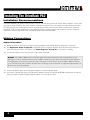
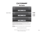
Quick Start Guide
Welcome to the
[r]evolution.
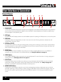
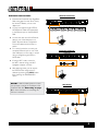
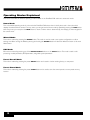
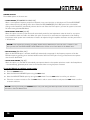
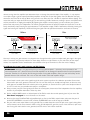
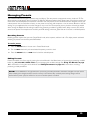
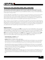
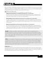
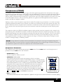
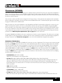
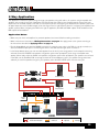
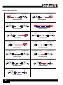
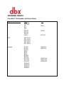
MONO/STEREO FULL RANGE (1X2, 2X2)
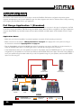
1 GETTING STARTED
Before making any audio connections, perform the following:
sEnsure power to your mixer, DriveRack, and amplifier(s) are turned off.
sTurn the attenuators on all power amplifiers or powered speakers all the way down.
sSet the +4 dBu/-10 dBV switch on the back panel of the DriveRack to match the nominal output operating level of your mixer.
sMake the audio connections per your application using the system diagrams to the right for reference.
sPower up the mixer, then the DriveRack, then your amplifiers or powered speakers.
Left Main
Powered Speaker
To Power
Outlet
Right Main
Powered Speaker
Wireless Router
Mixer
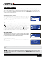
2 RUN THE SETUP WIZARD
PRESS
sPress the WIZARD button.
sSelect the “RUN ALL WIZARDS” option using the DATA WHEEL.
sSelect the “NEW SETTINGS” option using the DATA WHEEL.
sFollow the on-screen instructions and make the desired configuration
or
or
Windows® or Mac®
Computer
iOS® or Android®
Tablet
selections.
LOUDSPEAKER MANAGEMENT SYSTEM
Left Speaker
iOS® or Android®
Phone
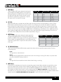
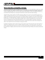
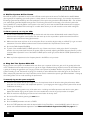
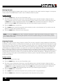
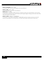
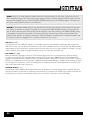
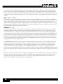
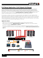
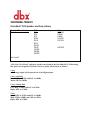
MONO/STEREO 2-WAY (1X3, 1X4, 2X3, 2X4)
TURN & PRESS
TO SELECT
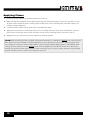
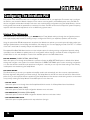
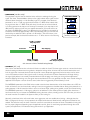
3 CALIBRATE THE SYSTEM
R L/Mono
or
Right Speaker
sWhen you reach the AutoEQ™ Wizard, connect the optional dbx RTA-M
measurement microphone to the RTA MIC INPUT and place it in a mic
stand. If you don’t have the RTA-M mic, skip AutoEQ and go to step 4.
sPlace the RTA-M microphone as shown in the illustration to the right –
the placement of the microphone should form an equilateral triangle with
the loudspeakers.
sFollow the DriveRack’s on-screen instructions.
RTA-M Mic
Placement
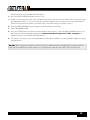
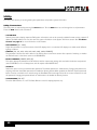
4 RING OUT THE SYSTEM FOR FEEDBACK
When you reach the AFS™ (Advanced Feedback Suppression™) Wizard,
ensure all your performance microphones are connected and follow the onscreen instructions to ring out the system for potential feedback. All mics
should be active, but there should be no signal present at the microphones
during this procedure.
High/Mid Amp
R
L
R
L
Low Amp
Left Main Speaker
Right Main Speaker
Left Sub Speaker
Right Sub Speaker
R
L
R
L
To Power
Outlet
Wireless Router
Mixer
R L/Mono
or
or
®
Windows or Mac
Computer
®
or
®
iOS or Android
Tablet
®
iOS® or Android®
Phone
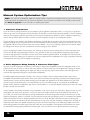
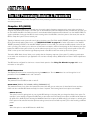
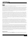
MONO/STEREO 3-WAY (1X5, 1X6, 2X5, 2X6)
High Amp
R
L
R
L
Mid Amp
R
L
R
L
Low Amp
R
L
R
L
5 CONNECT TO YOUR NETWORK
Left Main Speaker
Right Main Speaker
Left Sub Speaker
Right Sub Speaker
Connect the DriveRack’s Ethernet port to your network or wireless
router for network setup and control using the free control app for Mac®,
Windows®, Android®, and iOS® devices. Visit www.dbxpro.com for further
details.
NOTE: A DHCP enabled switch or router must be used for
DriveRack control.
© 2013 Harman. dbx Professional Products is a registered trademark of Harman. All features and specifications are subject to change.
All rights reserved. Macintosh, iPhone, iPad, iTunes, and App Store are trademarks of Apple Inc., registered in the U.S. and other
countries. Apple is not responsible for the operation of this device or its compliance with safety and regulatory standards. Windows is
a registered trademark of Microsoft Corporation in the United States and other countries. Android is a registered trademark of Google
Incorporated.
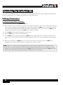
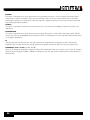
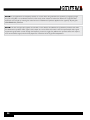
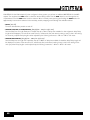
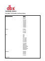
LEGEND
L
R
To Power
Outlet
Analog Audio Connections
Omit Connection For Mono Systems
Ethernet Connection
Wi-Fi Signal
IEC Power Cord
Left Channel
Right Channel
Wireless Router
Mixer
or
or
Windows® or Mac®
Computer
or
iOS® or Android®
Tablet
iOS® or Android®
Phone
R L/Mono
WHAT’S IN THE BOX
PRODUCT REGISTRATION
DOWNLOAD THE OWNER’S MANUAL
sDriveRack PA2 Processor
sPower Cable
To activate your warranty and stay informed on important
product updates, please register your product at www.dbxpro.
com.
In our effort to be more environmentally responsible and provide the most
up-to-date product information, owner’s manuals can now be downloaded
online at www.dbxpro.com.
®
LOUDSPEAKER MANAGEMENT SYSTEM
dbx Professional Products
801.566.8800
dbxpro.com
PN: 5033257-C
®
Owner’s Manual
IMPORTANT SAFETY INSTRUCTIONS
WARNING FOR YOUR PROTECTION
READ THE FOLLOWING:
KEEP THESE INSTRUCTIONS
HEED ALL WARNINGS
FOLLOW ALL INSTRUCTIONS
The symbols shown above are internationally accepted symbols that warn
of potential hazards with electrical products. The lightning flash with
arrowpoint in an equilateral triangle means that there are dangerous
voltages present within the unit. The exclamation point in an equilateral
triangle indicates that it is necessary for the user to refer to the owner’s
manual.
These symbols warn that there are no user serviceable parts inside the
unit. Do not open the unit. Do not attempt to service the unit yourself.
Refer all servicing to qualified personnel. Opening the chassis for any
reason will void the manufacturer’s warranty. Do not get the unit wet. If
liquid is spilled on the unit, shut it off immediately and take it to a dealer
for service. Disconnect the unit during storms to prevent damage.
The following is indicative of low
altitude use; do not use this product
above 2000m.
U.K. MAINS PLUG WARNING
A molded mains plug that has been cut off from the cord is
unsafe. Discard the mains plug at a suitable disposal facility.
The apparatus shall not be exposed to dripping or splashing liquid and no object filled with liquid,
such as vases, shall be placed on the apparatus.
CLEAN ONLY WITH A DRY CLOTH.
FOR INDOOR USE ONLY.
DO NOT BLOCK ANY OF THE VENTILATION OPENINGS. INSTALL IN ACCORDANCE WITH THE MANUFACTURER’S INSTRUCTIONS.
DO NOT INSTALL NEAR ANY HEAT SOURCES SUCH AS RADIATORS, HEAT REGISTERS, STOVES, OR
OTHER APPARATUS (INCLUDING AMPLIFIERS) THAT PRODUCE HEAT.
ONLY USE ATTACHMENTS/ACCESSORIES SPECIFIED BY THE MANUFACTURER.
UNPLUG THIS APPARATUS DURING LIGHTNING STORMS OR WHEN UNUSED FOR LONG PERIODS
OF TIME.
Do not defeat the safety purpose of the polarized or grounding-type plug. A polarized plug has two
blades with one wider than the other. A grounding type plug has two blades and a third grounding
prong. The wide blade or third prong are provided for your safety. If the provided plug does not fit
your outlet, consult an electrician for replacement of the obsolete outlet.
Protect the power cord from being walked on or pinched particularly at plugs, convenience receptacles, and the point where they exit from the apparatus.
Use only with the cart stand, tripod bracket, or table specified by the manufacture, or sold with
the apparatus. When a cart is used, use caution when moving the cart/apparatus combination to
avoid injury from tip-over.
NEVER UNDER ANY CIRCUMSTANCES SHOULD
YOU INSERT A DAMAGED OR CUT MAINS PLUG
INTO A 13 AMP POWER SOCKET.
Do not use the mains plug without the fuse cover in place.
Replacement fuse covers can be obtained from your local
retailer. Replacement fuses are 13 amps and MUST be ASTA
approved to BS1362.
If you want to dispose this product, do not mix it with general household waste. There is a
separate collection system for used electronic products in accordance with legislation that
requires proper treatment, recovery and recycling.
Private households in the 25 member states of the EU, in Switzerland and Norway may return their used
electronic products free of charge to designated collection facilities or to a retailer (if you purchase a similar
new one).
For Countries not mentioned above, please contact your local authorities for a correct method of disposal.
By doing so you will ensure that your disposed product undergoes the necessary treatment, recovery and
recycling and thus prevent potential negative effects on the environment and human health.
Refer all servicing to qualified service personnel. Servicing is required when the apparatus has
been damaged in any way, such as power-supply cord or plug is damaged, liquid has been spilled
or objects have fallen into the apparatus, the apparatus has been exposed to rain or moisture, does
not operate normally, or has been dropped.
POWER ON/OFF SWITCH: The Power switch used in this piece of equipment DOES NOT break the
connection from the mains.
MAINS DISCONNECT: The plug shall remain readily operable. For rack-mount or installation where
plug is not accessible, an all-pole mains switch with a contact separation of at least 3 mm in each
pole shall be incorporated into the electrical installation of the rack or building.
If connected to 240V supply, a suitable CSA/UL certified power cord shall be used for this supply.
This Equipment is intended for rack mount use only.
IMPORTANT SAFETY INSTRUCTIONS
ELECTROMAGNETIC COMPATIBILITY
This device complies with part 15 of the FCC Rules and the Product
Specifications noted on the Declaration of Conformity. Operation
is subject to the following two conditions:
• this device may not cause harmful interference, and
• this device must accept any interference received, including
interference that may cause undesired operation.
DECLARATION OF CONFORMITY
Manufacturer’s Name: dbx Professional Products
Manufacturer’s Address: 8760 S. Sandy Parkway
Sandy, Utah 84070, USA
declares that the product:
Product name:
dbx DriveRack PA2
Note: Product name may be suffixed by the EU.
Operation of this unit within significant electromagnetic fields should be
avoided.
• use only shielded interconnecting cables.
Notice For Customers If Your Unit Is Equipped With A Power Cord.
WARNING: THIS APPLIANCE SHALL BE CONNECTED TO A MAINS SOCKET OUTLET WITH A PROTECTIVE
EARTHING CONNECTION.
The cores in the mains lead are coloured in accordance with the following code:
BLUE - Neutral
• T he core which is coloured green and yellow must be connected to the terminal in
the plug marked with the letter E, or with the earth symbol, or coloured green, or
green and yellow.
• The core which is coloured blue must be connected to the terminal marked N or
coloured black.
• The core which is coloured brown must be connected to the terminal marked L or
coloured red.
This equipment may require the use of a different line cord, attachment plug, or both,
depending on the available power source at installation. If the attachment plug needs to
be changed, refer servicing to qualified service personnel who should refer to the table
below. The green/yellow wire shall be connected directly to the units chassis.
L
N
LIVE
NEUTRAL
E
EARTH GND
WIRE COLOR
Normal
Alt
BROWN
BLACK
BLUE
WHITE
GREEN/YEL
Safety:
IEC 60065 -01+Amd 2
EMC:
EN 55022:2006
EN 55024:1998
FCC Part 15
Supplementary Information:
BROWN - Live
As colours of the cores in the mains lead of this appliance may not correspond with the
coloured markings identifying the terminals in your plug, proceed as follows:
CONDUCTOR
None
conforms to the following Product Specifications:
SAFETY INSTRUCTIONS
GREEN and YELLOW - Earth
Product option:
The product herewith complies with the requirements of the:
Low Voltage Directive 2006/95/EC
EMC Directive 2004/108/EC.
RoHS Directive 2011/65/EC
WEEE Directive 2002/96/EC
With regard to Directive 2005/32/EC and EC Regulation 1275/2008 of
17 December 2008, this product is designed, produced, and classified as
Professional Audio Equipment and thus is exempt from this Directive.
Rex C. Reed
Director, Engineering
Signal Processing
8760 S. Sandy Parkway
Sandy, Utah 84070, USA
Date: October 9, 2013
GREEN
European Contact: Your local dbx Sales and Service Office or
WARNING: If the ground is defeated, certain fault conditions in the unit or in the system to which it is connected can result in full line voltage between chassis and earth
ground. Severe injury or death can then result if the chassis and earth ground are
touched simultaneously.
WARNING:
• Apparatet må tilkoples jordet stikkontakt.
• Apparaten skall anslutas till jordat uttag.
• Laite on liitettävä suojakoskettimilla varustettuun pistorasiaan.
Harman Signal Processing
8760 South Sandy Parkway
Sandy, Utah
84070 USA
Ph: (801) 566-8800
Fax: (801) 568-7583
®
Warranty
1. The warranty registration card that accompanies this product must be mailed within 30 days after purchase date to validate
this warranty. You can also register online at www.dbxpro.com. Proof-of-purchase is considered to be the responsibility of the
consumer. A copy of the original purchase receipt must be provided for any warranty service.
2. dbx warrants this product, when purchased new from an authorized U.S. dbx dealer and used solely within the U.S., to be
free from defects in materials and workmanship under normal use and service. This warranty is valid to the original purchaser
only and is non-transferable.
3. dbx liability under this warranty is limited to repairing or, at our discretion, replacing defective materials that show evidence
of defect, provided the product is returned to dbx WITH RETURN AUTHORIZATION from the factory, where all parts and labor
will be covered up to a period of two years. A Return Authorization Number must first be obtained from dbx. The company shall
not be liable for any consequential damage as a result of the product’s use in any circuit or assembly.
4. dbx reserves the right to make changes in design or make additions to or improvements upon this product without incurring
any obligation to install the same additions or improvements on products previously manufactured.
5. The foregoing is in lieu of all other warranties, expressed or implied, and dbx neither assumes nor authorizes any person to
assume on its behalf any obligation or liability in connection with the sale of this product. In no event shall dbx or its dealers be
liable for special or consequential damages or from any delay in the performance of this warranty due to causes beyond their
control.
Technical Support & Service
If you require technical support, contact dbx Technical Support. Be prepared to accurately describe the problem. Know the
serial number of your device – this is printed on a sticker attached to the chassis. If you have not already taken the time to fill
out your warranty registration card and send it in, please do so now. You may also register online at www.dbxpro.com.
Before you return a product to the factory for service, we recommend you refer to this manual. Make sure you have correctly
followed installation steps and operating procedures. For further technical assistance or service, please contact our Technical
Support Department at (801) 566-8800 or visit www.dbxpro.com. If you need to return a product to the factory for service, you
MUST first contact our Technical Support Department to obtain a Return Authorization Number.
NO RETURNED PRODUCTS WILL BE ACCEPTED AT THE FACTORY WITHOUT A RETURN AUTHORIZATION NUMBER.
Please refer to the Warranty information, which extends to the first end-user. After expiration of the warranty, a reasonable
charge will be made for parts, labor, and packing if you choose to use the factory service facility. In all cases, you are
responsible for transportation charges to the factory. If the product is still under warranty, dbx will pay the return shipping.
Use the original packing material if it is available. Mark the package with the name of the shipper and with these words in red:
DELICATE INSTRUMENT, FRAGILE! Insure the package properly. Ship prepaid, not collect. Do not ship parcel post.
®
Table of Contents
Overview ����������������������������������������������������������������������� 2
Introduction������������������������������������������������������������������������������������������������� 2
Features������������������������������������������������������������������������������������������������������� 3
User Interface & Connectors ����������������������������������� 4
Front Panel������������������������������������������������������������������������������������������������� 4
Rear Panel�������������������������������������������������������������������������������������������������� 6
Installing The DriveRack PA2 ���������������������������������� 8
Installation Recommendations��������������������������������������������������������������� 8
Making Connections�������������������������������������������������������������������������������� 8
Audio Connections������������������������������������������������������������������������������� 8
Network Connections��������������������������������������������������������������������������� 9
Applying Power���������������������������������������������������������������������������������������10
Getting Started ����������������������������������������������������������11
Menu Navigation Overview�������������������������������������������������������������������11
Operating Modes Explained����������������������������������������������������������������12
The Home Screens��������������������������������������������������������������������������������13
Configuring The DriveRack PA2 ���������������������������14
Using The Wizards���������������������������������������������������������������������������������14
About Speaker & Amplifier Tunings���������������������������������������������������17
Manual System Optimization Tips������������������������������������������������������18
1. Crossover Frequencies�����������������������������������������������������������������18
2. Driver Alignment Delay, Polarity, & Crossover Filter Types��18
3. Gain Structure & Limiters�������������������������������������������������������������19
4. Balance The System’s Frequency Response�������������������������21
5. EQ The System At The Venue����������������������������������������������������22
6. Ring Out The System With AFS������������������������������������������������22
Operating The DriveRack PA2 �������������������������������24
Editing Parameters���������������������������������������������������������������������������������24
Managing Presets�����������������������������������������������������������������������������������25
Recalling Presets���������������������������������������������������������������������������������25
Editing Presets�������������������������������������������������������������������������������������25
Storing Presets������������������������������������������������������������������������������������26
Copying Presets����������������������������������������������������������������������������������26
RTA�������������������������������������������������������������������������������������������������������������45
Utility�����������������������������������������������������������������������������������������������������������46
Power-Up Functions ������������������������������������������������ 47
Initialize With Mutes On������������������������������������������������������������������������47
System Lockout���������������������������������������������������������������������������������������48
Factory Reset�������������������������������������������������������������������������������������������49
Soft Reset�������������������������������������������������������������������������������������������������49
Application Guide �����������������������������������������������������50
Full Range Application 1 (Standard)�������������������������������������������������50
Full Range Application 2 (Sub-Satellite System)���������������������������51
Full Range Application 3 (All Outputs Full Range)������������������������52
2-Way Application����������������������������������������������������������������������������������53
3-Way Application����������������������������������������������������������������������������������54
Preset List �������������������������������������������������������������������55
DriveRack PA2 Control Application ���������������������56
Device Requirements�����������������������������������������������������������������������������56
Networking������������������������������������������������������������������������������������������������57
Networking Overview�������������������������������������������������������������������������57
Network Security���������������������������������������������������������������������������������57
Network Troubleshooting�������������������������������������������������������������������57
Technical Information ����������������������������������������������59
Firmware Updates�����������������������������������������������������������������������������������59
DSP Block Diagram�������������������������������������������������������������������������������60
Cable Diagrams���������������������������������������������������������������������������������������61
Ethernet Cable Diagrams������������������������������������������������������������������61
Audio Cable Diagrams�����������������������������������������������������������������������62
Dimensions�����������������������������������������������������������������������������������������������63
Specifications������������������������������������������������������������������������������������������64
Additional Resources ����������������������������������������������65
dbx Website���������������������������������������������������������������������������������������������65
DriveRack PA2 Product Page�������������������������������������������������������������65
dbx Support����������������������������������������������������������������������������������������������65
dbx User’s Forum �����������������������������������������������������������������������������������65
The PA2 Processing Modules & Parameters ���� 27
Graphic EQ (GEQ)��������������������������������������������������������������������������������27
Parametric EQ (AutoEQ, HIGH, MID, LOW PEQ)�����������������������29
Advanced Feedback Suppression (AFS)�����������������������������������������31
Subharmonic Synthesis (SUB)�����������������������������������������������������������35
Compressor (COMP)����������������������������������������������������������������������������37
Delay����������������������������������������������������������������������������������������������������������39
Crossover (XOVER)�������������������������������������������������������������������������������41
Limiter��������������������������������������������������������������������������������������������������������43
1
®
Overview
Introduction
The DriveRack® PA2 represents the next generation of PA loudspeaker management processing from dbx®. With dynamics,
EQ, feedback suppression, crossover, subharmonic synthesis, and delay processing, the DriveRack PA2 provides all the
processing you need between your mixer and amplifiers to optimize and protect your loudspeakers.
Building upon the same great features that made the DriveRack PX, PA, and PA+ so popular, the DriveRack PA2 adds the
latest advancements in dbx’s proprietary AutoEQ™ and AFS™ (Advanced Feedback Suppression™) algorithms, a new input delay
module for delaying the sound system to the backline, Ethernet control via an iOS®, Android®, Mac®, or Windows® device, and
much, much more!
The updated Wizards in the PA2 are more intuitive and powerful than ever and offer step-by-step assistance with setup
configuration, loudspeaker optimization, and system feedback elimination. The updated AutoEQ™ uses frequency sweeps rather
than pink noise and allows you to take up to four measurements for analysis, providing an extremely accurate, timely, and
non-intrusive automatic EQ experience. And the enhanced AFS algorithm is now even faster and more accurate at eliminating
feedback, without adversely affecting your system’s tone.
The most exciting new feature of the DriveRack PA2 is the network and Wi-Fi control capabilities using the free DriveRack
PA2 control application available for iOS, Android, Mac, and Windows compatible devices. Now you can configure and adjust
the settings of your loudspeaker management processor from anywhere in the venue!
You say your speaker or amplifier tunings aren’t available in the DriveRack PA2’s default tuning list? No problem. Use the
DriveRack PA2 control app to connect to the ever-growing online database, where you can instantly download and apply the
latest tunings from JBL®, Crown®, dbx, other DriveRack PA2 users, and more – no firmware update necessary!
With supported crossover configurations for full range, 2-way, and 3-way systems, enhanced algorithms and functionality, and
a stylish new design, the DriveRack PA2 was engineered to continue the DriveRack legacy of great-sounding and affordable
loudspeaker management processing.
Thanks for choosing dbx.
2
®
Features
• Setup Wizard For Easy System Configuration
• Level Assist For System Level Balancing
• AutoEQ™ For Fast & Accurate Room Equalization Using 8-Band Parametric EQ
• AFS™ For Ringing Out The System & On-The-Fly Feedback Suppression
• 31-Band Graphic EQ For Tailoring The System’s Frequency Response To Taste
• Subharmonic Synthesizer
• dbx® Compression
• Pre-Crossover Delay For Aligning The Sound System To The Stage Backline
• Crossover With Support For Full Range, 2-Way, & 3-Way Configurations
• Stereo 8-Band Output Parametric EQs For Speaker Tunings
• Stereo PeakPlus® Output Limiters
• Stereo Output Driver Alignment Delays For 2-Way & 3-Way Systems
• Real-Time Analyzer
• White/Pink Noise Generator
• 2 XLR Inputs
• 6 XLR Outputs
• Front-Panel XLR RTA Mic Input With 15V Phantom Power
• Support For Mono Or Stereo Inputs
• Support For Mono Or Stereo Subwoofers
• Bright, 6-Segment Input & Output Meters
• Front-Panel Output Mute Buttons
• Security Lockout
• 24-Bit A/D & D/A Converters
• 48 kHz/32-Bit Floating Point Processing
• dbx Type IV™ Conversion Prevents Clipping Of The A/D Converters
• Easy-To-Read LCD Display
• Storage Memory Locations For Up To 75 User Presets
• Various Speaker & Amplifier Tunings Included
• Additional Tunings & Presets Available For Download Using The Free DriveRack PA2 Control Application
3
®
User Interface & Connectors
Front Panel
1
2
1. RTA MIC INPUT
3
5
4
6
8
7
10 12
9
11
13
Connect the dbx RTA-M measurement microphone (sold separately) to this balanced XLR input jack for easy calibration
of your sound system using the built-in Wizards. Or use the RTA for manual adjustments and system troubleshooting.
This jack supplies +15V phantom power.
2. LCD Display
This LED backlit LCD display provides the visual feedback required for operating the PA2 processor from the front panel.
3. BACK Button
Pressing this button will navigate back one level in the current menu tree. Pressing this button multiple times will
navigate back to the Home screen.
4. DATA Wheel (SELECT)
This data wheel is used for scrolling and loading presets, scrolling menus, selecting on-screen options and parameters,
and editing selected on-screen options and parameters. Some functions are performed by turning the data wheel and
others are performed by pressing the data wheel.
5. WIZARD Button
Pressing this button enters the Wizard menu, where you can select a specific Wizard to run or run all Wizards in
succession. For more information on the different Wizards, see ‘Using The Wizards’ on page 14.
6. PRESET Buttons
The STORE and RECALL buttons are used to store and recall presets. For more information on storing, copying, and
recalling presets, see ‘Managing Presets’ on page 25.
7. UTILITY Button
Pressing this button enters the Utility menu, where you can get information about the PA2’s firmware and network
settings and configure global system settings which dictate how the PA2 operates. See ‘Utility’ on page 46 for
information on the options and parameters available in the Utility menu.
8. INSTANT ACCESS Buttons
Pressing each of these buttons opens the menu for the corresponding processing module, where you can edit the
parameters pertaining to each processing module. Pressing the RTA button enters the Real-Time Analyzer, where you
can monitor the system’s signal using the optional dbx RTA-M microphone for fine-tuning and troubleshooting the
system.
4
®
9. INPUT Meters
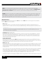
These 6-segment LED meters display the input signal
level strength and available headroom, and range from
SIG (signal present) to 0 (dBFS). These meters monitor
the signal level right after the A/D converter and will
light when the signal level is greater than or equal to
the values shown in the table to the right.
Input LEDs
dBFS
(switch set to +4 dBu)
(switch set to -10 dBV)
0
-0.1
19.9 dBu
7.7 dBV
3
-3
17 dBu
4.8 dBV
10
-10
10 dBu
-2.2 dBV
15
-20
5 dBu
-7.2 dBV
20
-30
0 dBu
-12.2 dBV
SIG
-48
-28 dBu
-40.2 dBV
10. CLIP LEDs
When these LEDs light, it indicates that the PA2’s inputs are being overdriven and input clipping is occurring. These
LEDs feature a peak hold function, so they will remain lit for a short period of time after the signal level drops back
below the clip point. The dbx Type IV™ conversion system built into the PA2 will clamp down on excessively loud input
signals and prevent the A/D converters from clipping. If you’re lighting these LEDs, you will need to reduce the output
level of your mixer. If you have the +4dBu/-10dBV switch on the back panel of the PA2 set to the -10dBV position, but
you’re sending a +4dBu signal to the PA2’s inputs, this may cause these LEDs to light prematurely. If this occurs, set
this switch to the +4dBu position (mute the PA2’s outputs before doing so).
11. OUTPUT Meters
These 6-segment LED meters display the output signal level
strength and available headroom, and range from SIG (signal
present) to 0 (dBFS). These meters monitor the signal level after the
limiter modules and output MUTE buttons and will light when the
signal level is greater than or equal to the values shown in the table
to the right.
Output LEDs
dBFS
dBu
0
-0.1
19.9
3
-3
17
10
-10
10
15
-15
5
20
-20
0
SIG
-48
-28
12. TH (THRESHOLD) Meters
These multi-colored threshold LEDs indicate output limiter activity within the specified output channels. The three
colored states are:
• Green
The signal level is under threshold.
• Yellow
The signal level has approached the threshold and some minor limiting is occurring. This state is only active when
the limiter’s OverEasy™ setting is turned on.
• Red
The signal level has exceeded the limiter’s threshold and limiting is occurring.
13. MUTE Buttons
Pressing each of these buttons will mute the corresponding output channel. When activated, the signal will be muted
prior to the output meter. The state of these outputs are global and are not stored to presets. However, the state of
these buttons will be retained after a power cycle. The MUTES POWERUP function, available in the Utility menu, lets
you configure the PA2 to always power on with all outputs muted. See ‘Utility’ on page 46 for more information on
this feature. You can also press and hold any of these MUTE buttons upon power up to force the PA2 to initialize with all
outputs muted. See ‘Initialize With Mutes On’ on page 47 for more information on this feature.
5
®
Rear Panel
1
4
120V
5
50/60Hz
2
3
6
1. IEC AC Power Inlet
Connect the included IEC power cord to this power inlet. The DriveRack PA2 ships from the factory configured for one
of two specified power voltage ranges, they are:
• 100-120V, 50Hz/60Hz
• 220-240V, 50Hz/60Hz
Note: Ensure the screening under this outlet matches the voltage specification in your country before applying
power to the PA2.
2. Ethernet Port
This RJ45 connector is used for updating the firmware and controlling the PA2 from a networked device using the free
DriveRack PA2 control app. See ‘Network Connections’ on page 9 and ‘Networking’ on page 57 for more
information.
Note: A DHCP enabled switch or Wi-Fi router is required to assign an IP address to the PA2 for network
control.
3. USB Port
This USB connector is used for updating the PA2’s firmware. See ‘Firmware Updates’ on page 59 for more
information.
4. Outputs 1-6
These six electronically balanced XLR outputs correspond to the low, mid, and high processing modules in the
PA2’s output processing section. Crossover frequency points can be extended to overlap each other in the crossover
processing module, allowing multiple outputs to be configured for full range operation if required.
5. Inputs 1-2
Connect your mixer to these electronically balanced XLR connectors. These inputs can be configured for stereo or mono
applications in the Wizard. The input sensitivity of these jacks are affected by the +4dBu/-10dBV switch.
6
®
6. Input Switches
These switches are recessed to prevent accidental switching. You may need to use the tip of your fingernail or an object
with a pointy tip, such as a pen, to activate these switches.
• +4dBu/-10dBv Switch
This switch sets the PA2’s input sensitivity. Select the +4dBu option (switch out) when connecting a mixer or device
which has a nominal output operating level of around +4dBu. Select the -10dBV option (switch in) when connecting
a mixer or device which operates at a lower “consumer” level, such as some DJ mixers or a consumer device with
unbalanced output connectors (such as RCA connectors). If you’re not sure what the nominal output operating level
of your mixer is, check the product’s manual or contact the manufacturer. It’s advisable to only switch this switch
when your amplifiers are powered off or the DriveRack PA2’s outputs are muted.
• Ground Lift Switch
The ground lift switch lifts the pin 1 chassis ground on both input XLR connectors. In most applications, this switch
should be left in the out (disabled) position. If hum becomes an issue and is caused from a ground loop between
your mixer and PA2, try engaging this switch. It’s advisable to only switch this switch when your amplifiers are
powered off or the DriveRack PA2’s outputs are muted.
7
®
Installing The DriveRack PA2
Installation Recommendations
FOR RACK MOUNT USE ONLY. Install the PA2 in your 19” rack with the provided rack screws. When installed in a rack, make
sure there is proper ventilation. The sides and back of the device should be free of any obstruction that would prevent airflow.
The PA2 should not be mounted above or below anything that generates excessive heat. Ambient temperatures should not
exceed 950 F (350 C) when equipment is in use. Although the unit is shielded against radio frequency and electromagnetic
interference, extremely high fields of RF and EMI should be avoided where possible.
Making Connections
Audio Connections
1. Ensure the power is turned off on all interconnecting equipment and the PA2 before making audio connections.
2. See ‘Application Guide’ on page 50 for application notes and system diagrams which can be used for reference
when connecting the PA2 to your system. See ‘Cable Diagrams’ on page 61 for information on cabling.
3. Connect the outputs of your mixing console to the inputs of the PA2.
Note: The +4dBu/-10dBV switch on the back panel of the PA2 must be set to the correct position for your
application in order to avoid performance issues. +4dBu is referred to as “pro level” and will be the correct setting for
most applications, as most pro and semi-pro mixers will output a nominal level of around +4dBu. -10dBV is referred
to as “consumer level” and will need to be used when connecting a source which has an output level approximately 12
dB lower than pro level equipment.
4. Connect the PA2’s outputs to the designated amplifier or powered speaker inputs.
5. If you plan to calibrate the system using the built-in Wizards, connect the optional dbx RTA-M measurement microphone
using a microphone cable of suitable length and place it in a microphone stand.
8
®
Network Connections
Wired Ethernet Switch
1. Download and install the free DriveRack
PA2 control app from the iTunes Store,
the Android® Market, or from www.
dbxpro.com.
DriveRack PA2
®
120V
50/60Hz
120V
50/60Hz
Ethernet Switch With DHCP Enabled
2. Connect a straight-through CAT5e or
CAT6 Ethernet cable (sold separately)
to the Ethernet port on the DriveRack
PA2.
3. Connect the other end of the Ethernet
cable to one of the LAN ports on a
DHCP (Dynamic Host Configuration
Protocol) enabled network router or
switch.
Mac® or Windows®
Computer
4. For a wired connection, connect your
120V
50/60Hz
computer’s Ethernet port to one of the
DriveRack PA2
other LAN ports on the router or switch
using a straight-through CAT5e or
CAT6 cable.
Wired Ethernet Router
DriveRack PA2
120V
50/60Hz
120V
5. If using
a Wi-Fi
connect
to
Ethernet
Switchrouter,
With DHCP
Enabled
50/60Hz
Ethernet Router With DHCP Enabled
the Wi-Fi network using your Wi-Fi
equipped computer or device.
1
WAN
2
3
4
LAN
6. After applying power, you can ensure
the PA2 has been assigned an IP
address by pressing the UTILITY button
then selecting the SYSTEM INFO
option.
Mac® or Windows®
Computer
120V
50/60Hz
Mac® or Wi
Computer W
Mac® or Windows®
Computer
Note: A DHCP enabled switch or router
must be used to assign an IP address to the
DriveRack PA2
DriveRack PA2. See ‘Networking’ on page
57 for more information on controlling the
PA2 over a network.
Wi-Fi Router
DriveRack PA2
120V
50/60Hz
Ethernet Router With DHCP Enabled
1
WAN
2
3
4
LAN
1
WAN
2
3
4
LAN
Wi-Fi Router With DHCP Enabled
or
Mac® or Windows®
Computer
Mac® or Windows®
Computer With Wi-Fi
or
Android® or iOS®
Tablet
Android® or iOS®
Smartphone
9
®
Applying Power
1. Ensure your power amplifiers or powered speakers are turned off.
2. Make sure that the included IEC power cable provided with your PA2 has the proper connector for connection to your
AC power outlet and that the power screening under the IEC power inlet on the back panel of the PA2 matches your
country’s voltage requirements.
3. Connect the power cable to the AC power inlet on the PA2’s back panel.
4. Apply power to the PA2 by connecting the other end to an available AC power outlet. Since the PA2 does not have a
power switch, an AC power strip or power conditioner can be used for switching power to the PA2 on and off.
5. Apply power to your mixer then your power amplifiers or powered speakers.
Note: When powering up a fully configured and connected PA system, it is advisable to ALWAYS turn on the mixer and
PA2 first then turn on your amplifiers or powered speakers. It’s also a good idea to ensure you’re not passing audio to the
mixer’s outputs (or ensure your mixer’s master faders are all the way down) before applying power to the amplifiers. When
powering down the system, you should ALWAYS power down the amplifiers first, wait about 10 seconds to allow them to
discharge, then power down the mixer and PA2. In other words, every time you use your system, the power amps should be
the last components turned on and the first components turned off.
10
®
Getting Started
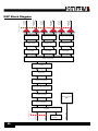
Menu Navigation Overview
The DriveRack PA2’s user interface was carefully designed to provide logical navigation and avoid deeply nested menus. The
menu navigation is laid out as shown in the below diagram.
HOME MODE
Press SELECT
Configuration
Home Screen
Dynamic Meters
Home Screen
RTA
Home Screen
System Info
Home Screen
Press RTA Button
Press RECALL Button
Press STORE Button
Press UTILITY Button
Press GEQ Button
Press AFS Button
Press SUB Button
Press XOVER Button
Preset Recall Menu
Preset Store Menu
Utility Menu
Graphic EQ Menu
AFS Menu
Subharmonics Menu
Compressor Menu
Crossover Menu
Turn DATA Wheel / Press SELECT
Turn DATA Wheel / Press SELECT
Turn DATA Wheel / Press SELECT
Press LIMITER Button
Limiter Menu
Turn DATA Wheel / Press SELECT
Turn DATA Wheel / Press SELECT
Turn DATA Wheel / Press SELECT
Turn DATA Wheel / Press SELECT
Mid Limiter Menu
Low Limiter Menu
AutoEQ Menu
High PEQ Menu
Delay Menu
Turn DATA Wheel / Press SELECT
Turn DATA Wheel / Press SELECT
Turn DATA Wheel / Press SELECT
Mid PEQ Menu
Low PEQ Menu
High Limiter Menu
Mid Limiter Menu
Low Limiter Menu
Press & Hold DELAY Button
Turn DATA Wheel / Press SELECT
Press WIZARD Button
High Limiter Menu
Parametric EQ Menu
Turn DATA Wheel / Press SELECT
Press DELAY Button
Low Crossover Menu
Press & Hold PEQ Button
Turn DATA Wheel / Press SELECT
Press PEQ Button
Mid Crossover Menu
Press & Hold LIMITER Button
Turn DATA Wheel / Press SELECT
High Crossover Menu
Press & Hold XOVER Button
Press COMP Button
RTA Menu
Run All Wizards
Wizard Menu
Turn DATA Wheel / Press SELECT
Turn DATA Wheel / Press SELECT
Turn DATA Wheel / Press SELECT
Turn DATA Wheel / Press SELECT
Run Setup Wizard
Run AutoEQ/
Level Assist
Run AFS Wizard
Wizard Options
11
®
Operating Modes Explained
This section describes the different operating modes available in the DriveRack PA2 and how to enter each mode.
Home Mode
This is the default operating mode. It is the mode the DriveRack PA2 enters when it initially boots and is the mode which
displays the selected Home screen. From any menu, you can get back to Home mode by repeatedly pressing the BACK button.
How many times you must press the BACK button to return to Home mode is determined by how deeply you have navigated in
the current menu.
Wizard Mode
This mode is entered by pressing the WIZARD button. This mode is used to create a new system configuration or edit an
existing one. When running the Wizards, pressing and holding the WIZARD button will abort the Wizard and return to the main
Wizard menu.
Edit Mode
Edit mode is entered by pressing any of the INSTANT ACCESS buttons or the UTILITY button. This mode is used to edit
processing module parameters, RTA parameters, and global system parameters.
Preset Recall Mode
This mode is entered by pressing the preset RECALL button and is used to load an existing factory or user preset.
Preset Store Mode
This mode is entered by pressing the preset STORE button and is used to store the current preset to a user preset memory
location.
12
®
The Home Screens
The Home screen is the first screen which appears in the LCD display after the DriveRack PA2 fully initializes (this is also
referred to as “Home mode”). There are four Home screens to choose from, providing the instant visual feedback you need,
when you need it. All Home screens will display the currently loaded preset number and name, so you always know which
preset is currently loaded. To toggle between Home screens, simply press the DATA WHEEL from Home mode. Below is a
description of each available Home screen.
D D D
L L L
RTA
XOVER
DLY
CMP
SUB
MIC
AFS
R
GEQ
L
AEQ
1 Preset 1
USER
P P P
Configuration Home Screen
This is the default Home screen. This screen shows the configuration and signal flow
of the currently loaded preset. The far left of the screen indicates input configuration.
The far right of the screen indicates output configuration. All the blocks in-between
represent the processing modules.
LH
RH
LM
RM
LL
RL
Configuration Home Screen
Dynamics Meter Home Screen
This
screen
shows dynamic processing activity in the input compressor and
LIMITER
O Home
LOW
LIMITER
O LOW
MIDMID
LIMITER
O O limiter
LIMITER
output
modules. The meters on the left of this screen show threshold activity. The
LIMITER
O O HIGH
HIGH
LIMITER
5
3012 12
5 0
icon indicates the 30
signal
is 0below
threshold and no dynamics processing is occurring.
O O COMPRESSOR
COMPRESSOR
The
icon
indicates
that
the
signal
level is within the “OverEasy™” region and some
EDIT
EDIT
LOW
LIMITER
O only
minor compression or limiting is beginning to occur (this icon will
light
if the
MID LIMITER
O
dynamics processor is configured for “OverEasy” operation). TheO icon
that
HIGHindicates
LIMITER
30
12
the signal is over threshold and full compression or limiting is occurring.
The meters on
O
COMPRESSOR
EDIT
the right show how much gain reduction is occurring in each processing
module.
1 Preset 1
Preset1 1
1 1Preset
1 Preset 1
RTA Home Screen
This Home screen provides quick access to the Real-Time Analyzer. When the optional
dbx RTA-M measurement microphone is connected to the RTA Mic Input, this RTA can
be used for manually fine-tuning and troubleshooting the system.
System Info Home Screen
This Home screen shows the currently installed firmware version and the IP address
assigned to the PA2.
5 0
EDIT
O
COMPRESSOR
O
O
O
HIGH LIMITER
MID LIMITER
LOW LIMITER
30
12 5 0
Dynamics Meter Home Screen
1 Preset 1
EDIT
RTA
RTA Home Screen
1 Preset 1
USER
Version: 1.1.3.0
IP: 192.168.0.2
System Info Home Screen
Note: After a power cycle, the DriveRack PA2 will return to the Home screen selected before the unit was powered
down.
Note: The TIME OUT feature in the Utility menu will determine if the DriveRack PA2 will return to the Home screen
after a period of inactivity and how long it will wait before timing out. See ‘Utility’ on page 46 for further information on
the TIME OUT feature.
13
®
Configuring The DriveRack PA2
This section of the manual describes how to configure the DriveRack PA2 for your application. The easiest way to configure
the PA2 is to use the built-in Wizards. However, for the veteran sound engineers and DriveRack power users, the PA2 can
also be configured and tweaked manually. Power users can create the basic configuration using the Setup Wizard, or load an
existing preset, then tweak the parameters as necessary from there. The RTA can be used to analyze the system’s frequency
response and make manual adjustments or for troubleshooting system issues.
Using The Wizards
The PA2 Wizards are accessed by pressing the WIZARD button. These Wizards walk you through the configuration process
with simple, step-by-step instructions, making it easy to configure the PA2 for your amplifiers, speakers, and the venue.
Using the optional dbx RTA-M measurement microphone, the Wizards can optimize your sound system by helping adjust your
left/right speaker balance, low/mid/high level balance, and analyzing your room and applying accurate room EQ – in a fraction
of the time it would take to manually analyze and calibrate the system.
The updated DriveRack PA2 Wizard section now also includes options for altering existing configurations (presets), making
it possible to use the Wizards to update portions of a configuration without having to recreate the whole configuration from
scratch. Below is a list and description of each of the available options in the PA2’s Wizard menu.
RUN ALL WIZARDS [CURRENT SETTINGS, NEW SETTINGS]
Select this option to run through all the Wizards in succession. Select the NEW SETTINGS option to default all the Wizard
settings and configure a new system from scratch. Select the CURRENT SETTINGS option to alter an existing configuration
or to view the selections made when the preset was configured – note that you can only view these settings if the currently
loaded preset was created using the Setup Wizard.
RUN SETUP WIZARD
This Wizard allows you to enter your speaker and amplifier models and automatically sets the crossover, output parametric
EQ, driver alignment delay, polarity, and limiter settings. The Setup Wizard in the PA2 now stores all selections made with the
preset. So if you load a preset that was created using the Setup Wizard, all the selections made during creation can be viewed
at any time by entering the Setup Wizard. The available options in this menu are:
• RUN ALL SETUP
Select this option to run through the entire Setup Wizard (which consists of all Setup Wizard items listed below).
• RUN INPUT SETUP [MONO, STEREO]
Select this option to switch the input configuration between mono and stereo.
• RUN GEQ SETUP [DUAL MONO, STEREO LINKED]
Select this option to switch the GEQ configuration between dual mono and stereo linked.
• RUN SPEAKER/AMP SETUP
Select this option to update speaker and/or amp selections (tunings).
14
®
RUN AutoEQ/LEVEL ASSIST
Right Speaker
Left Speaker
Right Speaker
1/3rd
1/3rd
1/3rd
Speakers & Mic Form an
Equilateral Triangle
RTA-M Mic
Placement 2
RTA-M Mic
Placement 1
AutoEQ Mic Position 3 (Optional)
Left Speaker
1/3rd
Right Speaker
1/3rd
1/3rd
RTA-M Mic
Placement 1
Reference
AutoEQ Mic Position 4 (Optional)
Left Speaker
1/3rd
Right Speaker
1/3rd
1/3rd
rd
1/3
The Level Assist and AutoEQ mic position
1 measurements should be taken with
the microphone placed out in front of
the speakers the same distance as the
speakers are apart, so that the three
components form an equilateral triangle,
as shown in the Level Assist/AutoEQ Mic
Position 1 diagram.
Left Speaker
AutoEQ Mic Position 2
rd
The diagrams to the right show the
recommended Level Assist and AutoEQ
RTA-M mic positions. When running
AutoEQ, you will be prompted to select how
many mic positions you would like AutoEQ
to analyze – the selections are: 2, 3, or 4.
Level Assist/AutoEQ Mic Position 1
1/3
When used with the optional dbx RTA-M
measurement microphone, this Wizard
helps you balance the left/right speaker
levels, the low/mid/high speaker levels
(for 2-way and 3-way systems), and
automatically equalizes the speakers to the
current room environment. After selecting
this option, you can select whether you
would like to run both the Level Assist and
AutoEQ functions, Level Assist only, or
AutoEQ only.
RTA-M Mic
2/3
RTA-M Mic
rds
Placement 1
Placement 1
Each time you move the RTA-M mic
Reference
Reference
position it should move approximately
RTA-M Mic
1/3rd the distance the speakers are apart
Placement 3
from the initial “RTA-M Mic Placement 1
RTA-M Mic
Reference”, as shown in the AutoEQ Mic
Placement 4
Position 2-3 diagrams. Mic position 4 is the
exception as it should be placed 2/3rds the distance from the RTA-M Mic Placement 1 Reference. For example, if your
speakers were 20 feet apart, you would move the microphone approximately 7’ (20 * (1/3) = 6.6) from the RTA-M Mic
Placement 1 Reference for mic positions 2-3 and approximately 14’ from the RTA-M Mic Placement 1 Reference for mic
position 4. However, as a general rule of thumb and for the sake of simplicity, a distance of 5’ should work well for most
venues. If the recommended placement of the mic in positions 2-4 is not possible, just place the mic in a position that differs
from the other measurement positions.
RUN AFS WIZARD
This Wizard walks you through the process of ringing out the system to provide higher system gain before feedback. This is
accomplished by pushing your system into feedback so AFS can detect the initial frequencies which cause feedback and notch
them using Fixed filters. When the AFS Wizard is complete, it will automatically enable the Live filters, for automated protection
during system use.
15
®
WIZARD OPTIONS
The available options in this menu are:
• AutoEQ TARGET [RECOMMENDED PA CURVE, FLAT]
When a sound system’s frequency response is flattened, it can sound a bit thin on the bottom end. The AutoEQ TARGET
option makes up for this by adding a bass boost. Select the RECOMMENDED PA CURVE option (this is the default
setting) to allow AutoEQ to automatically enhance the low end. Select the FLAT option if you want the system to be tuned
flat when running the AutoEQ Wizard.
• LEVEL ASSIST AUTO TRIM [ON, OFF]
When this option is turned on, Level Assist will automatically make fine level adjustments under the hood for any system
level mismatches which are 3 dB or less. When this option is turned off, no automatic level adjustments will be made by
Level Assist and all system level mismatches will need to be adjusted using the amplifier attenuators until they are within a
1 dB tolerance.
Note: Level adjustments made by the LEVEL ASSIST AUTO TRIM function cannot be seen or edited. To clear
them you must turn the LEVEL ASSIST AUTO TRIM function off then re-run Level Assist in the Wizard menu.
• MIC RESPONSE [dbx RTA-M, FLAT]
When the dbx RTA-M option is selected, AutoEQ will automatically compensate for the frequency response of the dbx
RTA-M microphone, providing more accurate AutoEQ results. Select the FLAT option if using a measurement microphone
other than the dbx RTA-M.
• SETUP AUTO NAMING [ON, OFF]
When this option is on, the PA2 will automatically name presets based on the speaker selections made in the Setup Wizard
– the automatically generated preset name can still be edited when storing the preset if desired.
To use the Wizards to configure a new system:
1. Press the WIZARD button.
2. Select the RUN ALL WIZARDS option using the DATA wheel.
3. Select the NEW SETTINGS option by turning the DATA wheel. Press the DATA wheel to confirm your selection.
4. Follow the on-screen instructions. Turn the DATA wheel to edit on-screen selections and press the DATA wheel to confirm
on-screen selections.
Note: Pressing and holding the WIZARD button at any time during the Wizard procedure will exit the current Wizard
and return to the main Wizard menu.
16
®
About Speaker & Amplifier Tunings
The PA2 has a Setup Wizard to help you configure your sound system. When you run the Setup Wizard, it will ask you to select
the make and model of your speakers and amplifiers from a list of available options, referred to as “tunings”. There are speaker
tunings and amplifier tunings. When you select your speakers from the tuning list, the PA2 will automatically configure the
crossover, output PEQs, polarity, and in some cases, driver alignment delays. When you select your amplifiers from the tuning
list, the PA2 will automatically set your output gains (located in the crossover) and limiter threshold settings.
The PA2 includes a variety of speaker and amplifier tunings from JBL®, Crown®, and more. If your particular tunings are not
available in the PA2’s preset tuning list, you can use the DriveRack PA2 control app to access the online database where you
can find additional tunings. If you can’t find tunings for your particular speakers or amplifiers, you will need to select the NOT
LISTED option in the PA2’s Setup Wizard. The PA2 will automatically set usable default settings which may sound and work
just fine, however, you may wish to manually calibrate the PA2 in order to realize the full potential of your sound system and
ensure your loudspeakers are protected. Providing full details on how to manually calibrate a sound system is beyond the
scope of this manual, but there is an abundance of free information available on the internet which covers these topics. This
section of the manual will cover some of the basics to help get you started.
Loudspeaker manufacturers perform extensive testing on their products and will often provide much of the data necessary to
optimize their loudspeaker systems. Check your speaker manufacturer’s website or contact them directly to see if they can
provide a speaker tuning data sheet that you can use for manually entering speaker tuning parameters into the PA2. These
tuning data sheets will typically include recommended crossover, polarity, driver alignment delay, and sometimes, parametric EQ
settings.
17
®
Manual System Optimization Tips
Hint: You may want to disable the TIME OUT feature located in the Utility menu before performing any of the following
system optimization procedures. This will ensure the PA2 does not revert back to the Home screen throughout the process.
See ‘Utility’ on page 46 for more information on disabling this feature.
1. Crossover Frequencies
If you can’t find any tuning information for your speakers, get the speaker’s specification sheet – it can give you a good idea
where to set some of your high pass and low pass filters in the PA2’s crossover by providing the speaker’s or driver’s frequency
response. This frequency response spec shows you the range of frequencies the speaker or driver is capable of reproducing
and can help you better determine where to set the crossover frequency settings for your loudspeaker system.
If you’re bi-amping main speakers, the speaker manufacturer should be able to provide you with the recommended crossover
frequency settings. If you’re using subs and can’t find recommended crossover frequency settings, you will need to dial it in by
ear. Typically, subs and mains will be crossed over at around 100 Hz – this is a good setting to start with. You can then adjust
the settings from there to fine-tune the sub/main crossover settings by ear if required.
If you’re configuring a simple full-range system (not requiring any active crossover settings) then you don’t necessarily need
to enter any speaker tuning parameters. However, it is a good idea to take note of the speaker’s frequency response spec
and set the high pass filter in the PA2’s crossover at the lower frequency specified (35 Hz, for example). This will prevent the
subsonic low-end from robbing you of headroom in your amp and prevent the loudspeakers from trying to reproduce extremely
low frequencies which they are not capable of reproducing.
2. Driver Alignment Delay, Polarity, & Crossover Filter Types
Once the crossover frequencies are dialed in, you’re ready to optimize the loudpeakers’ phase. All loudspeaker drivers in the
system need to work in unison in order for the sound system to sound its best. This is accomplished by matching the polarity
for all loudspeaker drivers, adjusting driver alignment delay to time align any physical driver offsets, and selecting the best
crossover filter type/slope settings for your particular loudspeakers.
The PA2’s output polarity parameter (located in the crossover module) is used to match polarity between drivers. Some
bi-ampable main speakers require certain drivers to be inverted in polarity when operating in bi-amped mode (bypassing the
internal passive crossover network). When selecting any bi-ampable main speaker from the PA2’s speaker tuning list, such
polarity inversion will be performed for you automatically. If you can’t find PA2 tunings for your particular bi-ampable main
speaker model, check the loudspeaker’s spec sheet or documentation, or contact the speaker manufacturer as they will usually
be able to provide this information.
If you’re unable to find polarity information for your speakers, or just want to verify your drivers are in phase, you can do some
investigative work using a tone generator or some sine wave tone samples (which can be downloaded for free online). To
do so, take note of the crossover frequency setting used between the drivers being tested and play a sine wave tone of that
frequency through the system. For example, if you’re testing the woofer and high frequency driver in a bi-amped main speaker
cabinet and the active crossover frequency between the two is set at 2.5 kHz, play a 2.5 kHz sine wave tone through the
system. Both drivers will reproduce the tone simultaneously as long as the crossover frequency is indeed within the range of
frequencies both drivers are capable of reproducing. You can then invert the polarity on the PA2’s high outputs and find out
which setting provides the loudest signal (note that results are most noticeable if sound pressure levels between the drivers
are matched). The setting which provides the loudest signal is the one which is more “in phase”. Note that if you’re using
18
®
subs, you can perform the same test between the low driver in the main speaker and sub to ensure polarity for all drivers are
matched. You will also want to make sure that all drivers/speakers reference absolute polarity. This means that all drivers would
push outwards then inwards during each cycle. If the absolute polarity is reversed, the drivers would move in the opposite order
(inwards then outwards). If using subs, you can use the subs for absolute polarity reference – just make sure the low driver in
the mains matches the sub polarity then match the high driver to the low driver in the mains. If you’re using bi-amped speakers
with no subs, more extensive testing may be necessary to determine each driver’s absolute polarity.
Once polarity is matched for all drivers in the system, you’re ready to optimize the crossover filter types and driver alignment
delays. The “polarity” test mentioned in the previous paragraph can also be used for determining which crossover filter types
work best with your speakers and if driver alignment delay is necessary. Play the selected sine tone through the system (once
again, the sine tone frequency should match the set crossover frequency of the drivers being tested) and invert the polarity on
one of the two drivers being tested – as previously mentioned, this test works best if the sound pressure levels of both drivers
are matched. Adjust the driver’s levels until the most phase cancellation is achieved. Try adjusting the driver alignment delay for
each driver to see if any further phase cancellation can be achieved – set it for the most phase cancellation. Note that most
applications won’t require any driver alignment delay. For more information on setting driver alignment delays, see ‘Delay’ on
page 39.
Once you’ve dialed in the driver alignment delay, perform this same “polarity” test while auditioning different combinations of
filter types in the PA2’s crossover to find the combination of settings which provide the most phase cancellation. When done,
make sure to switch the polarity back to the proper setting so the drivers will again be in phase.
Changes to all these settings can be difficult to judge when heard in the context of the whole system, but by zeroing in on
the specific crossover frequency, matching levels, and inverting polarity on one of the drivers, you are free to experiment
with different settings to determine the best settings for your loudspeaker system. Adjust each of these parameters until the
most signal cancellation is achieved then switch the polarity back so the drivers are once again in phase. Maximizing these
parameters using this test will allow your system to work in harmony and improve its frequency and phase response.
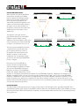
3. Gain Structure & Limiters
Now that the crossover settings are optimized and the loudspeaker drivers are in phase, it’s time to calibrate the gain structure
of the system. This will provide ample headroom for all system components in the signal chain and optimize your system’s
signal-to-noise ratio.
Your amplifiers play a vital role in system setup, because they are the last devices in the signal chain before your loudspeakers
and offer the greatest amount of gain (that is their job after all). If your amplifiers are setup incorrectly you will not be using
your system to its fullest potential and could potentially cause damage to your loudspeakers. When you select your amplifiers
in the Setup Wizard, the PA2 will automatically set the limiter thresholds and gain structure between the PA2 and amplifiers. If
your amplifiers are not available in the Setup Wizard, you should choose the NOT LISTED option. The following section explains
how you would go about manually optimizing the system’s gain structure and set the built-in limiters to protect your amplifiers
from clipping.
Gain structure refers to aligning the gain of each device so that the input circuits of all devices clip at the same time – this
allows you to know exactly how much headroom you have in the entire system by simply looking at the mixer’s main output
meter and optimizes the noise floor of the entire sound system. Quite often PA systems are setup with the amplifier input
attenuator controls turned all the way up, in the incorrect assumption that this is the only way to get the maximum level out of
the sound system. Setting up your amplifiers in such a manner can help prevent someone from raising your amp attenuators
and damaging the system (this is sometimes required for permanent install applications and requires the output gain be
reduced in the device feeding the amplifier), however, your noise floor will likely suffer in doing so. Amplifiers are fixed gain
19
®
devices, turning down the amplifier input attenuators does not change the potential output of the amplifier – it only requires
more input voltage to get full output power. Many amplifiers will clip with an input level greater than +6 dBu when the input
attenuators are turned all the way up. Most mixing consoles can deliver well over +18 dBu of output level before clipping. This
means that with your amps turned all the way up, you are sacrificing 12 dB of headroom, resulting in poorer noise performance
and the potential risk of clipping the amplifier. By adjusting the amplifier controls properly, you can maximize your system’s
performance and protect your loudspeakers. The following diagram illustrates the previous example and shows how it can be
easily remedied by simply lowering the input attenuators on the amplifier to apply 12 dB of attenuation, effectively lowering the
signal level entering the amplifier by 12 dB and fitting the signal within the operational headroom constraints of the amp.
Before
+18 dBu
After
Amp clips 12 dB
before mixer!
+18 dBu
+18 dBu
Both amp and mixer
now clip at 18 dBu
12 dB difference
+6 dBu
0
+18 dBu
0
Mixer master output faders
set to unity gain (performance level)
Amplifier attenuators
turned all the way up
Mixer master output faders
set to unity gain (performance level)
Amplifier attenuators lowered
to apply 12 dB of attenuation
Mixer Max Output
Level: +18 dBu
Amplifier Max Input
Level: +6 dBu
Mixer Max Output
Level: +18 dBu
Amplifier Max Input
Level: +18 dBu
One way to set up your gain structure is to play pink noise through the entire system and adjust each gain stage in the signal
chain in succession using the clip indicators on each device. If there is no clip indicator on your mixer then use the output
meters; most reputable console manufacturers use red LEDs at the top of the meters to show the onset of clipping.
To calibrate the system’s gain structure and PA2 limiters:
Warning! Although it is highly unlikely that you are using tube amplifiers – since they are not practical for live
sound reinforcement use – please note that some tube amplifiers can be damaged if operated without a load (the speaker)
connected. Therefore, do not perform the following procedure if using tube amplifiers unless you have verified they can be
operated without a load connected. This is not an issue with modern solid state amplifier designs.
1. You will need to send a pink noise signal through the entire system to perform this calibration procedure. Some mixers
have a built-in pink noise generator, which will work. You can also check your smartphone’s app store, as there are many
audio apps now available which have a built-in pink noise generator, or search online for a pink noise sample and burn it
to a CD or load it into your portable music player or smartphone.
2. Once you have your pink noise signal, power down the sound system, disconnect all the loudspeakers from the amplifiers,
and turn all your amplifier attenuators all the way down.
3. Set the +4dBu/-10dBV switch on the back panel of the PA2 to match the nominal operating level of your mixer. See
‘Rear Panel’ on page 6 for more information on this switch.
4. Now, turn the mixer, DriveRack PA2, and amplifiers back on. Go into the PA2’s output limiters and ensure they are all
turned OFF, OVEREASY is turned to OFF, and their THRESHOLD’s are set all the way up to 0.0 dB.
5. Set your mixer’s main output faders to unity gain (0). Play or enable the pink noise. If the pink noise signal is being fed to
a mixer channel, set the mixer channel’s fader to unity gain (0). Adjust the gain/trim control of the channel (or pink noise
level if using the mixer’s built-in noise generator) until the mixer’s main meters read 0 VU.
20
®
6. Raise the mixer’s main output faders until the INPUT CLIP LEDs on the PA2 just begin lighting.
7. Now, go to each amp channel and slowly raise its attenuator until the amp channel’s clip LED just begins to light.
8. Go into one of the PA2’s limiter modules. Turn the limiter on and slowly lower the THRESHOLD parameter until the
corresponding amp channel’s clip LEDs just stop lighting. Don’t lower the limiter THRESHOLD parameter too far, just
far enough to hold the signal level just below the clip point of the connected amplifier. Do this for each active pair of
DriveRack outputs (i.e., High, Mid, and Low).
9. Turn down the pink noise and main output faders on the mixer then power down the system.
10. Reconnect your speakers to your amps.
11. Power up the system, ensuring to power up your amps last.
The system is now optimized to provide the loudest levels possible, with adequate headroom between devices, and with the
least amount of noise. Now, sit back, play your favorite music through the system, and slowly raise your mixer’s main output
faders. When the mixer’s main faders are set to unity gain (0), the system will now provide the highest sound pressure level
it is capable of. If the system is not loud enough when the mixer is set to unity gain, this is an indication that the system is
inadequate for the application, so you may want to consider amplifiers with greater output power – but still within the power
rating of your loudspeakers – or additional speakers and amplifiers. Most loudspeaker manufacturers recommend an amplifier
which provides 1.5 to 2 times the rated RMS power of the speaker. If the sound system is too loud when the mixer’s main
faders are set to unity, this indicates that you have more power than is required for the application and you can simply turn
down your mixer’s main output faders until the desired “performance level” is achieved.
4. Balance The System’s Frequency Response
Now that the crossover is configured, the loudspeakers are all in phase, the gain structure of the system is calibrated, and the
limiters are set, it’s time to balance the system’s overall frequency response by fine-tuning the amplifier attenuators. This step
is not always necessary, but can often help smooth out the system’s frequency response before applying any system EQ. You
can perform this “balancing” while listening to your favorite reference music and do it by ear. The music you choose to use
for reference should contain full-bandwidth audio and should be something you have spent much time listening to and are
extremely familiar with.
Since the gain structure is already set and the limiters calibrated, you will not want to raise your amplifier attenuators, as we’ve
already determined when we set the gain structure, setting them any higher will cause the amplifiers to clip. Instead you will
want to lower the amp attenuators for whichever frequency range (i.e., low, mid, or high) is too loud. For example, if the system
has too much midrange, turn down your mid amp attenuators. If the system has too much high end, turn down the high amp
attenuators. The goal is to achieve a somewhat balanced system.
Hint: Before making any final amp attenuator adjustments, you may want to take note of the position of all amp
attenuators or mark their settings. This way you can retain the reference amp attenuator settings above which the amplifiers
will clip. You may also want to mark or take note of any adjusted settings if you do end up making any final amp attenuator
adjustments to further balance the system.
21
®
5. EQ The System At The Venue
Now that the system is optimized for use, it’s time to EQ the sound system at the venue. The PA2’s built-in AutoEQ Wizard
does a great job of equalizing your sound system in a timely manner so we recommend using it. You can alter the parametric
EQ settings generated by AutoEQ or tailor the equalization of the system using the built-in GEQ (Graphic EQ) – this will leave
your automatically generated AutoEQ settings intact. The following instructions can be used to fine-tune the system after
running AutoEQ or to manually EQ the sound system in the event you don’t have the dbx RTA-M measurement microphone.
Note that using the DriveRack PA2 control app on a mobile device allows you to walk around the venue while making EQ
adjustments.
To EQ the system by ear using the GEQ:
1. Choose a music reference source that you are familiar with and that contains full-bandwidth audio material. Play the
reference music through the sound system. Turn the music up as close as possible to performance level (the level at
which the system will be used during performance).
2. Walk around the venue and listen to the sound system. Does it sound thin, bright, muddy, or muffled? Try to get an overall
assessment of how the different audience areas sound and what kind of improvements can be made.
3. Go into the PA2’s Graphic EQ (GEQ).
4. Try each of the available QUICK CURVE options. Do any of them sound close to what you’re after? If so, keep the
selection. You can proceed and fine-tune the system further by manually adjusting the GEQ’s frequency bands if you feel
it can be further improved. If none of the QUICK CURVE options sound right, set the QUICK CURVE parameter back to
MANUAL.
5. Make any further adjustments to the frequency bands in the GEQ to suit your taste.
6. Ring Out The System With AFS
Ringing out the sound system for feedback before use allows you to squeeze a little more gain out of the system before the
onset of feedback and can help ensure you’re not right at the edge of feedback during the performance. The AFS Wizard does
a great job of taking the guesswork out of ringing out the sound system for feedback. However, if you prefer to ring out the
system manually, you can. The benefits of doing so is the ability to select different filter width settings for the Fixed and Live
filters, and precisely determine how many Fixed filters can be used to maximize the system’s gain before feedback – freeing up
all remaining filters for Live mode use during the performance.
To manually ring out the system using AFS:
1. Perform a sound check and set up a rough mix for all microphones which will be active during the performance. When
done, take note of the mixer’s main output fader positions – your target gain when ringing out the system will be around
5 dB above this setting.
2. If noise gates are being used on any of the active mics – including vocal effect processors with built-in noise gates –
bypass them before ringing out the system. You can re-enable them once the ring-out procedure is complete.
3. Have the musicians stop playing and turn the main mixer faders all the way down.
4. Go into the AFS module by pressing the AFS button.
5. Turn AFS on.
6. Go to the MODE parameter and set it to FIXED.
7. Go to the TYPE parameter and select the desired width for the Fixed filters – select the MUSIC option for the most
precise and inaudible feedback suppression. See ‘Advanced Feedback Suppression (AFS)’ on page 31 for
22
®
further information on the available AFS TYPE options.
8. Go to the FIXED FILTERS parameter and set it to 12.
9. Ensure no sound is present at any of the microphones then slowly raise the main mixer faders until you reach your target
gain (described in step 1) or run out of Fixed filters, whichever happens first, then lower the main mixer faders back to
performance level (the level at which you had the mixer’s main faders during sound check in step 1).
10. Lower the FIXED FILTERS setting to change all unset Fixed filters to Live filters.
11. Set the AFS MODE to LIVE.
12. Go to the TYPE parameter and select the desired width for the Live filters – select the MUSIC/SPEECH option for the
best all around real-time feedback protection. See ‘Advanced Feedback Suppression (AFS)’ on page 31 for
further information on the available AFS TYPE options.
13. The system is now ready for use and any available Live filters will be available for on-the-fly feedback suppression during
the performance.
Note: When ringing out the system in Fixed mode, any sound detected by AFS will trigger filters to be set. Therefore,
make sure the microphones are active, but there is no signal present at the mics when AFS is active in Fixed mode.
23
®
Operating The DriveRack PA2
This section of the manual describes how to operate the DriveRack PA2 after you have initially configured and optimized the
system using the Wizards. This includes editing parameters and managing presets.
Editing Parameters
To edit a processing module’s parameters:
1. Press the module’s button (e.g., GEQ, AFS, SUB, etc.).
2. Some menus will offer a list, depending upon the currently loaded configuration, where you can select which module you
want to edit. For example, if you have configured a 3-way system and press the PEQ button, you will be presented with
a list containing the AutoEQ PEQ, HIGH PEQ, MID PEQ, and LOW PEQ. If you see such a list, turn the DATA wheel to
highlight the desired option then press the DATA wheel to make the selection.
3. Turn the DATA wheel to select the parameter you wish to edit.
4. Press the DATA wheel to edit the selected parameter.
5. Turn the DATA wheel to edit the setting. Press the DATA wheel then repeat steps 3-5 to make any further edits in the
current menu or use the alternative method of editing multiple parameters within a menu described in the following hint
box.
6. When done editing, press the BACK button to exit the menu. Note that you may have to press the BACK button
repeatedly to exit the menu, depending upon how deeply you’re nested in the menu.
HINT: When in a module’s edit menu, subsequent presses of the selected module’s button will navigate down the
selected column in the menu, allowing for quicker parameter editing by directly jumping from one parameter to the next.
For example, when editing the GEQ module, pressing the GEQ button with the right hand and turning the DATA wheel with
the left hand allows you to edit the frequency bands in the GEQ with much more efficiency.
24
®
Managing Presets
The DriveRack PA2 has two types of presets: user and factory. The user presets occupy preset memory locations1-75. The
factory presets occupy preset memory locations 76-100. The difference between these preset types is that factory presets are
meant to be used as templates and cannot be overwritten and user presets can be overwritten and are designed to store your
custom presets. You can load either a factory or user preset to start with, edit the preset or run the various Wizards to alter the
settings for your application, then store the changes to any one of the 75 user preset memory locations. All settings created
when running the Wizards and all settings located in the processing modules (e.g., GEQ, limiter, delay, crossover, etc.) will be
stored to the preset. The exceptions are the Utility and RTA settings, which are global and are not stored to individual presets.
Recalling Presets
Recalling presets requires that you enter Preset Recall mode, select a preset, and then load it. This helps prevent accidental
switching of presets from the front panel DATA wheel.
To recall a preset:
1. Press the RECALL button. You are now in Preset Recall mode.
2. Turn the DATA wheel until you have selected the preset you wish to load.
3. Press the RECALL button or DATA wheel to load the selected preset.
Editing Presets
Presets are edited one of two ways: by running the various Wizards in the Wizard menu, or by pressing a processing module’s
button (e.g., AFS, SUB, COMP, LIMITER, DELAY, etc.) and changing the module’s settings. See ‘Using The Wizards’ on page
14 for information on using the various Wizards. See ‘Editing Parameters’ on page 24 for information on editing
processing module parameters.
Note: The STORE button will light whenever a processing module’s parameters have been changed from their stored
value, indicating the changes need be stored to memory to be retained. Any unstored preset setting changes will be
retained after a power cycle, but will be lost as soon as another preset is recalled.
25
®
Storing Presets
Once you are satisfied with the changes made to a factory or user preset, you are ready to store the changes to a user preset
memory location. The STORE button is used to store modifications made to a preset.
To store a preset:
1. Press the STORE button. You are now in Preset Store mode.
2. The current name of the preset will be shown in the LCD display and you now have the option to keep the name or
rename the preset. If you do not wish to rename the preset proceed to step 3. If you do wish to rename the preset, turn
the DATA wheel to edit the highlighted character. Press the DATA wheel to select the next character for editing and
repeat. Pressing the DATA wheel repeatedly wraps around and cycles back through the characters.
3. Press the STORE button a second time.
4. Turn the DATA wheel to select the user preset memory location you wish to store the preset to. If you wish to store the
preset to its current memory location, leave as is.
5. Press the STORE button a third time to store the preset.
Hint: Pressing the STORE button 3 times in succession will perform a Quick Store function, allowing you to quickly
store changes made to a preset. Performing this operation will store the updated settings to the current memory location
with the current preset name.
Copying Presets
Presets can be copied from one memory location to another. This can come in handy for creating a backup of a preset within
the PA2 box, creating variations of similar presets (for example, you may have already configured a stereo sub preset for larger
shows and wish to copy it and create a mono sub preset for smaller shows), or for creating an initial preset template and then
copying that preset template for use at each venue you play. For example, let’s say you’re playing “Club X” this weekend and
you’ve already pre-configured the PA2 for your system (i.e., you have run all the Wizards and stored your template preset).
When you show up to Club X, you can copy your template preset to a new memory location and name it “Club X”. Now, run
through only the Wizards which must be run at the venue (i.e., AutoEQ, and AFS) then save the changes. Presto! Next time you
use your system at Club X, all you have to do is connect the system and recall the Club X preset – although you may wish to
consider re-ringing out the system with the AFS Wizard to ensure the system will provide the best protection possible for the
current venue conditions.
To copy a preset:
1. Recall the preset you wish to copy.
2. Press the STORE button. You are now in Preset Store mode.
3. The current name of the preset will be shown in the LCD display and you now have the option to keep the name or
rename the preset. If you do not wish to rename the preset proceed to step 4. If you do wish to rename the preset, turn
the DATA wheel to edit the highlighted character. Press the DATA wheel to select the next character for editing and
repeat. Pressing the DATA wheel repeatedly wraps around and cycles back through the characters.
4. Press the STORE button a second time.
5. Turn the DATA wheel to select the user preset memory location you wish to copy the preset to.
6. Press the STORE button a third time to copy the preset to the new preset memory location.
26
®
The PA2 Processing Modules & Parameters
This section of the manual provides descriptions of all the processing modules available in the DriveRack PA2 and their
associated parameters.
Graphic EQ (GEQ)
The 31-band GEQ module lets you manually tune the sound system’s frequency response and is meant to be used alone or
alongside the AutoEQ PEQ (which is set when you run the AutoEQ). In previous DriveRack models, the GEQ was set when you
ran the AutoEQ. AutoEQ in the PA2 now uses its own dedicated 8-band parameteric EQ (referred to as the “AutoEQ PEQ”) for
system equalization, freeing up the GEQ for custom-tuning tasks. Use AutoEQ to tune the system at the venue, then use the
GEQ to shape the system’s tone to taste by ear.
Typically, a flattened sound system will sound light on the bottom end. The PA2’s AutoEQ TARGET parameter compensates for
this by automatically applying bass boost – see ‘WIZARD OPTIONS’ on page 16 for further information on the AutoEQ
TARGET parameter. However, if the AutoEQ TARGET parmeter is set to FLAT, you could use the GEQ instead to tailor the low
end to your liking. This allows you to add some of that bottom end back in, while still maintaining the “flat” reference point (just
bypass the GEQ and the system is back to your flat reference point). Let’s say you have a DJ rig and also prefer a little more
“sizzle” on the top end. Just raise the high-frequency bands in the GEQ to add some extra top end to the system.
The built-in GEQ “Quick Curves” allow you to quickly alter the frequency response of the system. Try auditioning each option
to see which one works best for your application. You can then manually edit any GEQ bands from there if further adjustments
are required.
The GEQ can be configured for dual mono or stereo linked operation. See ‘Using The Wizards’ on page 14 for more
information on this option.
GEQ Parameters
The Graphic EQ menu can be accessed by pressing the GEQ button. Turn the DATA wheel to scroll through the list of
parameters. Press the DATA wheel to edit a selection.
GRAPHIC EQ [ON, OFF]
This parameter turns the GEQ module on and off.
QUICK CURVE [MANUAL, FLAT, MY BAND, SPEECH, PERFORMANCE, DJ]
This parameter allows you to select from preset EQ curves. Note that you can select one of these Quick Curves and then
further edit the individual GEQ bands manually from there if required. The following Quick Curve options are available:
• MANUAL (Restore)
This option is used for getting back to your original GEQ settings in the event that you change the Quick Curve option. For
example, if you’ve already configured the GEQ and you then select the FLAT Quick Curve option, the GEQ will be flattened
(all bands set to 0 dB). By then selecting the MANUAL Quick Curve option, the GEQ settings you had prior to selecting the
FLAT option will be restored. Note that previous settings cannot be restored after a power cycle or after recalling a different
preset.
• FLAT
Select this option to reset all GEQ bands to 0 dB (flat).
27
®
• MYBAND
This option is optimized for live music performance using a portable PA system in small to medium sized venues (small
coffee shops or clubs for example). It offers some low-end boost with low-mid cut, which enhances the low end while
preventing the system from sounding too muddy. The high end is slightly attenuated to remove any harshness and further
help optimize gain before feedback.
• SPEECH
This option is optimized for speech sound reinforcement. Use it to enhance the intelligibility of speech for spoken word
applications.
• PERFORMANCE
This option is optimized for live music performance using larger PA systems in larger sized venues (large clubs). This EQ
curve is very similar to the MYBAND option except that it does not attenuate the low mids and offers additional attenuation
on the highest frequencies.
• DJ
Selecting this option will boost the low and high frequencies and attenuate the mid frequencies and is optimized for
playback of pre-recorded material. This setting represents the popular “smiley face” EQ curve commonly used by DJs.
• FREQUENCY (20 Hz - 20 kHz) [-12 dB - +12 dB]
There are 31 Frequency parameters available for editing. These parameters allow you to select any one of the 31 available
frequency bands (ranging from 20Hz - 20kHz) for editing their gain. The gain of each frequency band can be adjusted in .1
dB increments.
28
®
Parametric EQ (AutoEQ, HIGH, MID, LOW PEQ)
There are two types of PEQs available in the PA2: the AutoEQ PEQ and the output PEQs (labeled LOW, MID, and HIGH).
The AutoEQ PEQ is an 8-band parametric EQ which resides in the input processing side of the PA2 (pre crossover) and
is automatically adjusted by the built-in AutoEQ Wizard. In most cases you will likely just look at the settings in the AutoEQ
PEQ to see how the system was equalized after running the AutoEQ Wizard. However, you can go into the AutoEQ PEQ and
manually adjust the settings if desired.
The 8-band HIGH, MID, and LOW PEQs reside in the output processing side of the PA2 (post crossover) and were designed
to be used exclusively for speaker tunings. In a perfect world, your loudspeaker drivers would exhibit ultra-flat frequency
response (what you put in, you get out). Unfortunately, loudspeaker drivers don’t have extremely flat frequency response by
design and require some help to achieve a more flat frequency response. The output PEQs allow you to compensate for this
fact and improve the frequency response of the loudspeaker system, before taking the room into account.
When you select your main and sub speakers in the Setup Wizard, the output PEQs will automatically be adjusted. By applying
speaker tuning EQ, loudspeaker frequency response can be improved. Keep in mind that selecting some speaker models in the
Setup Wizard won’t set any parametric EQ settings, so don’t be alarmed if you selected your speakers in the Setup Wizard and
no PEQ settings were set. These output PEQs can also be adjusted, so you can manually enter speaker tuning parameters if
your speakers aren’t listed and speaker tuning data sheets are available for your speaker models.
PEQ Parameters
The PEQ menus can be accessed by pressing the PEQ button. You will see a list of the available PEQs to select from. Which
options are available in the list will depend upon the current configuration. In all cases you will at least see the AutoEQ PEQ
and HIGH PEQ (PEQ for the HIGH outputs). If you’ve configured a 2-way system, you will also see a LOW PEQ for the LOW
outputs. If you’ve configured a 3-way system, you will see an additional MID PEQ for the MID outputs. Turn then press the
DATA wheel to select the desired PEQ module. Turn the DATA wheel to scroll through the list of parameters. Press the DATA
wheel to edit a selection. When in the PEQ menu, pressing and holding the PEQ button for approximately 2 seconds will
advance to the next active PEQ module from the list, wrapping around through the available modules.
• AutoEQ, HIGH, MID, or LOW PEQ [ON, OFF]
Turns the selected PEQ module on or off.
• FLATTEN [RESTORE, FLAT, MANUAL, AUTOEQ (AutoEQ Only)]
This parameter has two options in the output PEQs: RESTORE and FLAT. Select the FLAT option to zero out the selected
PEQ (set all bands to 0 dB). Select the RESTORE option to retrieve the settings you had before you selected the FLAT
option. Note that you can only restore PEQ settings as long as you do not power cycle the PA2 or load another preset.
The AutoEQ PEQ provides three options: FLAT, MANUAL, and AUTOEQ. Select the FLAT option to zero out the AutoEQ
PEQ (set all bands to 0 dB). The MANUAL option shows any manual adjustments you have made to the AutoEQ PEQ – if
you haven’t made any, the PEQ will be flat when the MANUAL option is selected. Select the AUTOEQ option to get back to
the PEQ settings that were set when you ran the AutoEQ Wizard.
• BAND(1-8) TYPE [BELL, LOW SHELF, HIGH SHELF]
This parameter selects the PEQ filter type. Use the BELL type to edit a range of frequencies, the LOW SHELF type to edit
all frequencies below a specified frequency, or the HIGH SHELF type to edit all frequencies above a specified frequency.
Each band (1-8) allows you to select between these three band type options, so any band can be a bell or shelving type
filter.
29
®
• BAND(1-8) FREQUENCY [20 Hz - 20 kHz]
This parameter adjusts the center/cutoff frequency of the selected EQ band.
• BAND(1-8) GAIN [-12 dB - +12 dB]
This parameter adjusts the gain of the selected EQ band.
• BAND(1-8) Q [0.1 - 15.909]
This parameter is only available with BELL type filters and adjusts the width of the selected PEQ filter. Lower Q settings
provide wider filters, affecting a wider range of frequencies when adjusted. Higher Q settings provide narrower filters, which
affect fewer frequencies when adjusted.
• BAND(1-8) SLOPE [3 dB/Octave - 14.295 dB/Octave]
This parameter is only available with LOW SHELF or HIGH SHELF type filters and adjusts the slope rate of the filter
beyond the cutoff frequency. Lower settings yield a more gradual slope. Higher settings produce a steeper slope.
30
®
Advanced Feedback Suppression (AFS)
Feedback is caused when an in-phase audio loop is created between an input transducer (such as a guitar pickup or
microphone) and an output transducer (a loudspeaker). The DriveRack PA2 includes the exclusive AFS™ (Advanced Feedback
Suppression™) algorithm to help combat this dreadful phenomenon.
The AFS algorithm in the PA2 is a little different than the AFS algorithm used in any previous dbx products. That’s because
the dbx engineers revisited the already-stellar AFS algorithm to see if they could improve it. And guess what? They did! The
updated AFS algorithm in the PA2 can now detect and eliminate feedback faster than ever before and with even higher
precision. The updated AFS algorithm offers the following enhancements:
• It is faster at eliminating the offending feedback frequency.
• It can better determine what is actually feedback, making it far less likely to set false triggers on feedback-like audio
sources, such as a flute.
• It can better determine how much attenuation is required to notch out the feedback, resulting in notch filters which aren’t as
deep and even less audible.
• It prevents the filters from being too narrow to tackle feedback at lower frequencies.
• It has better frequency resolution, which provides pinpoint accuracy and uses the narrowest filters possible.
• When lifting Live filters, the filters are lifted more gradually to better determine if it is safe to lift the filter, preventing blaring
feedback from suddenly returning.
AFS uses precision frequency detection and state-of-the-art processing to determine the exact range of feedback frequencies
to remove (instead of indiscriminately removing large sections of audio). In the past, graphic equalizers were used to eliminate
feedback from a system. This was an acceptable method for eliminating feedback, but when this method is put up against
precision notch filters, such as those found in AFS, it becomes very evident that using graphic equalizers for this task severely
affects the tone of the system. With AFS, the precision filters remove only a fraction of the frequency spectrum, eliminating
the feedback with far less audible artifacts. The below diagram shows a comparison of filter widths between the AFS filters,
conventional 1/3 octave EQ filters, and notch filters used in competitor’s feedback elimination processors.
Filter Precision Comparison Chart
31
®
HINT: AFS works best when the signal entering the PA2’s inputs is sufficient. This requires proper gain staging
between the mixer and PA2. If the signal level is too low, AFS may be slow to respond to feedback. See ‘Manual System
Optimization Tips’ on page 18 for further information on gain structure and ringing out the system with AFS.
NOTE: Signals sent to the PA2’s LEFT and RIGHT inputs are summed to mono before entering AFS for analysis. If the
signal feeding one of the PA2’s inputs is polarity inverted, AFS will not be able to detect feedback – as the feedback will
cancel out before being analyzed. If you experience problems with AFS not detecting feedback, check the polarity of the
signals/cables feeding the PA2’s inputs to ensure they have the same polarity.
AFS Parameters
The AFS menu can be accessed by pressing the AFS button. Turn the DATA wheel to scroll through the list of parameters.
Press the DATA wheel to edit a selection.
• AFS [ON, OFF]
Turns the AFS module on or off. If AFS is off, the filters are bypassed and the algorithm is halted (the filters are not
updated). If AFS is on, the filters are active and they are updated according to the currently selected mode (Fixed or Live).
Warning! If AFS is turned on and filters are set (in use), be careful when turning AFS off, as all filters will be
immediately removed from the signal path and sudden feedback could occur. It is recommended that you lower your
mixer output faders before turning AFS off.
• CLEAR MODE [NONE, LIVE ONLY, ALL]
This parameter selects which filters will be cleared when you perform the clear function. If the NONE option is selected,
filters cannot be cleared. If the LIVE ONLY option is selected, only the Live filters will be cleared when you perform the
clear function and the Fixed filters will be left alone. When the ALL option is selected, both Live and Fixed filters will be
cleared when performing the clear function.
• CLEAR <PRESS SELECT>
Selecting this option then pressing the DATA wheel triggers the clear function, which removes set AFS filters. The clear
function allows you to either clear only the Live filters or all AFS filters so you can ring out the system for a new venue. The
CLEAR MODE parameter selects which filters will be cleared when performing the clear function.
• MODE [FIXED, LIVE]
This parameter determines whether the AFS algorithm will set Live or Fixed filters. Select the FIXED mode option to initially
ring out the system for optimal gain before feedback using the Fixed filters (the microphones should be active during this
procedure, but there should be no signal present at the microphones). Fixed filters are “static” and will remain set until you
manually clear them.
Once you have rung out the system with the Fixed filters, set the mode to LIVE to further protect the system from feedback
during the performance using the Live filters. In Live mode, AFS uses logic to determine what is feedback and what is
not. The enhanced AFS algorithm in the PA2 can better distinguish between progam material and feedback, dramatically
lowering the probability of false Live filters being set on feedback-like music content, such as a flute.
Live filters are “dynamic” and will update as feedback conditions change. When all of the Live filters have been set, they will
32
®
begin to round robin – meaning that if all Live filters have been set and new feedback occurs, the first Live filter set will be
released then re-set at the new feedback frequency location. The Live filters can be set to release after a period of time by
enabling the LIVE LIFT option and adjusting the LIFT AFTER parameter. Note that when you run the AFS Wizard, AFS will
automatically switch between Fixed and Live mode operation behind the scenes.
• TYPE [SPEECH, MUSIC/SPEECH, MUSIC]
This parameter sets the width and sensitivity of the AFS filters. The available options are:
SPEECH (Constant bandwidth of 11 Hz below 76 Hz, constant Q of 7 at or above 76 Hz)
This option is optimized for speech sound reinforcement, where wider notch filters are less noticeable. Select this
option when using the sound reinforcement system for speech only. With this option selected, notch filters will be
wider, but will provide the fastest, most solid protection against feedback.
MUSIC/SPEECH (Constant bandwidth of 9 Hz below 260 Hz, constant Q of 29 at or above 260 Hz)
This option is optimized for live music sound reinforcement or speech and provides the best all-around protection. It
will provide the best combination of fast feedback suppression and precision, using filters slightly narrower and less
audible than the SPEECH setting, but slightly faster than the MUSIC setting. If you’re not sure which setting to use,
select this option.
MUSIC (Constant bandwidth of 8 Hz below 927 Hz, constant Q of 116 at or above 927 Hz)
This option is optimized for live music sound reinforcement and offers the highest level of sonic quality. When this
option is selected, the AFS algorithm will zero in on the offending feedback frequency, while leaving the surrounding
frequencies unscathed. With this option selected, the AFS filters will take slightly longer to set than when using the
MUSIC/SPEECH setting, although the difference in time will be quite negligible, but will be virtually inaudible.
NOTE: To guarantee that feedback is suppressed using the minimum number of filters possible, AFS may
automatically widen filters. For example, if you had selected the MUSIC setting and an adjacent frequency is feeding
back, AFS will detect both frequencies, and if they are in close enough proximity, will set a single, wider filter rather than
two narrow filters. Using a single, wider filter rather than two narrow filters will not alter the sonic quality and will ensure
that the maximum number of filters will always be available for use. Automatically adjusted filter widths will never be any
wider than the SPEECH setting.
Hint: You can change the TYPE parameter at any time when manually ringing out the system with AFS. This allows
you to use narrow notch filters in combination with wider notch filters. For example, you could set the TYPE parameter
to MUSIC then ring out the system in Fixed mode, switch over to Live mode, then set the TYPE parameter to MUSIC/
SPEECH for the Live filters. This would allow you to use the extremely narrow MUSIC notch filters for the Fixed filters
(providing the best sound quality possible), then use the slightly faster, wider MUSIC/SPEECH notch filters for the Live
filters (providing slightly faster feedback suppression during the performance).
• FIXED FILTERS [0 - 12]
This parameter sets how many of the AFS filters will be allocated as Fixed filters. After selecting how many filters will be
allocated as Fixed filters, all remaining filters will be allocated as Live filters. There are a total of 12 AFS filters available, so
the simple formula is: Total Filters Available - Selected Number of Fixed Filters = Number of Live Filters. For example, if you
select a FIXED FILTER setting of 8, you will have 4 Live filters available for use (12 - 8 = 4).
33
®
Hint: Since it’s not really possible to predict exactly how many Fixed filters you may need, a good setting to start
with is the default setting of 6. If after ringing out the system, you feel you need to squeeze a little more gain out of the
system before feedback, you can increase the FIXED FILTERS setting and run the AFS Wizard again or manually ring
out only the newly added Fixed filters in the AFS menu.
Note: If the FIXED FILTERS setting is changed after filters have been set, the filters will be cleared one by one as
you increase or decrease the setting. For example, if you decrease the FIXED FILTERS setting by one, the last Fixed
filter set will be cleared because the Fixed filter will be changed to a Live filter. Likewise, if the FIXED FILTERS setting
is increased by one (and thus the number of Live filters goes down), then the first Live filter set will be cleared. The
Fixed/Live filter allocation is indicated at the bottom of the LCD display in the AFS menu. “F” indicates Fixed filters and
“L” indicates Live filters. A highlighted F or L indicates a filter that is set, or in use.
• LIVE LIFT [ON, OFF]
This parameter turns the LIVE LIFT feature on and off. When turned on, this parameter essentially enables a timer. Turn
LIVE LIFT on when you want AFS to lift (release) Live filters after a predetermined time set by the LIFT AFTER parameter.
Higher fidelity can be restored to the system by lifting Live filters when they are no longer needed (for example, if a singer
steps to the front of the stage and triggers feedback, setting a Live filter, and then backs off).
• LIFT AFTER [5S - 60M]
When the LIVE LIFT parameter is turned on, this parameter determines how long it will take before AFS will attempt
to remove a set Live filter. The selectable options range from 5S (5 seconds) to 60M (60 minutes). The updated AFS
algorithm in the PA2 will slowly release Live filters by 3 dB increments to determine if it is safe to remove them. If it gets to
0 dB and no feedback reoccurs, the filters are completely lifted. If feedback attempts to reappear while releasing, the filters
are once again set and the timer resets. This helps prevent a sudden reoccurrence of blaring feedback in the event a Live
filter is still needed and needs to remain set.
• SELECTED FILTER [1 - 12]
This parameter selects between the available filters shown at the bottom of the LCD display when in the AFS menu and
provides information on each filter. “L” represents a Live filter and “F” represents a Fixed filter. As you select each filter, the
set frequency, Q, and amount of attenuation will be shown for the filter in the bottom of the LCD display.
34
®
Subharmonic Synthesis (SUB)
dbx’s subharmonic synthesis (or sub-synth) processing has been specifically optimized to enhance the low frequencies in
audio material and was designed for use in a variety of professional audio applications, including nightclub and dance DJ
mixing, theatre and film sound, music recording, live music performance, and broadcasting. Using traditional EQ to enhance this
extremely low frequency region can increase noise potential and stage rumble (low-frequency feedback) in live PA systems.
Another problem is that the audio source may not have sufficient low end in this region to boost or the mic used to capture the
sound may not capture these extremely low frequencies. Subharmonic synthesis creates synthesized low frequencies based
on some of the higher frequencies in the audio program and gives you noise free low-end enhancement. The subharmonic
module’s two separate bands of subharmonic synthesis provide additional control for creating a deep, smooth low-end
response.
The level meters available in the Subharmonic Synth menu show
overall effect level, 35-56 Hz effect level, and 24-36 Hz effect level.
Use these meters while adjusting the subharmonic synthesizer’s
parameters to see how much of the effect you are adding to the
mix.
LEVEL
36-56
24-36
-60
-40
-24
-12
-6
•
Subharmonic Synthesis Level Meters
0
Subharmonic Synthesis Parameters
The Subharmonic Synth menu can be accessed by pressing the SUB button. Turn the DATA wheel to scroll through the list of
parameters. Press the DATA wheel to edit a selection.
• SUBHARMONIC [ON, OFF]
This parameter turns the subharmonic synth module on and off.
• SUBHARMONICS [0% - 100%]
This parameter sets the overall level of the sub-synth effect.
• 36-56 HZ LEVEL [0% - 100%]
This parameter adjusts how much of the sub-synth effect is added between the 36 Hz to 56 Hz region. If the sound
becomes too “woofy” or “growly”, try turning this parameter down. You may find that a certain setting produces fine results in
one room, but produces too much “boominess” in another. If this occurs, adjust the parameter as needed.
• 24-36 HZ LEVEL [0% - 100%]
This parameter adjusts how much of the sub-synth effect is added between the 24 Hz to 36 Hz region. If your woofers are
bottoming out (making a ticking or popping sound), turn this parameter down. Enhance this frequency region less than the
36-56 Hz region (as shown in the above level meter screenshot) for more natural bass roll-off. Experimentation will pay off
with smooth, full, deeply extended bass.
Important! The subharmonic synthesis process produces extremely low-frequency audio signals that some
speakers may not be designed to reproduce. Attempting to achieve enhanced bottom end with these systems may not be
possible and may result in over-stressing or even damaging your loudspeakers. It is generally not a good idea to use this
feature without a subwoofer. In any case, please refer to your subwoofer speakers’ frequency response specification, and
avoid forcing them to reproduce low frequencies that they are not designed to reproduce.
35
®
NOTE: If you experience low-frequency artifacts on a voice when using subharmonic synthesis, try engaging a high
pass filter, using EQ, or a combination thereof on the vocal’s mixer channel to reduce the artifacts. If a high pass filter
and EQ are not enough, try lowering the overall amount of Subharmoic Synthesis applied to the signal by adjusting the
SUBHARMONICS parameter.
NOTE: The left and right input signals are summed to mono before the subharmonic synthesizer processes the audio.
The subharmonic synthesis effect signal is then output as a mono effect and mixed in with the unprocessed audio signal.
Any panned signals which contain enough low-frequency content to trigger the subharmonic synthesis effect will output a
mono summed effect signal, which will be played out of both the left and right PA loudspeakers.
36
®
Compressor (COMP)
A compressor is used to compress the dynamic range of the audio signal, bringing up the lower level portions of the signal
and restricting the higher level portions of the signal. In live sound applications, it is common to compress the audio at different
stages in the signal chain. For example, you may apply compression to individual instruments using the mixer’s insert points
and/or a group of instruments using the mixer’s bus or group inserts. You can also apply compression to the entire mix in order
to add some additional “body” to the sound and help “glue” the mix together. It’s this latter application that the compressor
module in the PA2 was designed to address.
Typically, you want to control the dynamic range where it’s needed. For example, using a compressor on an entire mix, without
compressing individual instruments, may not improve a mix where some instruments are much more dynamic than others. The
dynamic instruments still won’t sit right in the mix. You’ll have to increase their volume so their lower level signals aren’t lost in
the mix and then their louder level signals will just hit the compressor harder than everything else and suck everything down
with it.
The compressor module in the PA2 is a broadband compressor which provides overall mix compression and is located on the
input processing side of the PA2. The compressor module can help add the final touch of dynamics processing to the mix, but
should be used sparingly as this type of compression generally works best with lower ratio settings. A 1:5 to 2:1 ratio with 2-3
dB of compression should do the trick. It’s subtle, but it can help smooth things out and add a little extra girth to the sound
if set properly. Be careful not to apply too much compression, as doing so can have the adverse affect of making the sound
“smaller” or creating “pumping” or “breathing” artifacts.
NOTE: If using subharmonic synthesis, which is placed before the compressor, the strong low-frequency energy from
the sub-synth process can cause excessive compressor pumping/breathing. If you exhibit this type of behavior, try lowering
the subharmonic synthesis level and/or the compression ratio to eliminate the artifacts.
Compressor Parameters
The Compressor menu can be accessed by pressing the COMP button. Turn the DATA wheel to scroll through the list of
parameters. Press the DATA wheel to edit a selection.
• COMPRESSOR [ON, OFF]
Turns the compressor module on and off.
LOW LIM
O
• THRESHOLD [-60 dB to 0 dB]
MID LIMI
O
THRESHOLD METER
This parameter sets the level at which the compressor will kick in and begin
HIGH LIM
O
compressing the signal. The compressor Threshold Meter (shown to the right) indicates
LOW LIM
O
when signal is below threshold, above threshold, or in the OverEasy region. For example,
LIM
O
Signal Below ThresholdLOW
COMPRE
MID
LIMI
O
if the threshold parameter is set to -10 dB, any signal which exceeds -10 dB will be
MID LIMI
O
compressed, while any signal lower than -10 dB will be left alone (uncompressed).
HIGH LIM
EDIT
O
O ThresholdHIGH LIM
Typically, you will want to set the threshold parameter so that the lower levels of
Signal Above
the signal drop below
threshold
LOW LIMITER
LOW
LIMITER and the higher levels exceed threshold. This can O
O
O
COMPRE
MID LIMITER
O
LIMITER
O by MID
easily be achieved
looking
O
COMPRE
LOW
LIMITERat the compressor’s Threshold Meter and adjusting the
O
HIGH LIMITER
O
HIGH LIMITER
O
MIDOLIMITER
LOW LIMITER O
LOWthe
LIMITER
OTHRESHOLD
30
12 5 0
EDIT
30
12 alternates
5 0
parameter
until
meter
back and forth between the
and
Signal Approaching Threshold
O
COMPRESSOR
COMPRESSOR
MID LIMITER O O HIGH
MID LIMITER
O
O LIMITER
EDIT
12 5 0
(OverEasy™
Turned On)
icons
(or EDIT
, , andO icons
if30OVEREASY
is turned on).
HIGH LIMITER
HIGH LIMITER
EDIT
O
1 Prese
Prese
1
Preset
1
1
1 Prese
Preset 1
1Preset
1
11
Preset
Preset
1
1This
1
parameter determines how much compression is applied to the signal once it exceeds threshold. For example, applying
O 30 COMPRESSOR
12 5 0
O
O
COMPRESSOR
COMPRESSOR
EDIT
• RATIO [1:1 to Inf:1] EDIT
EDIT
30
12 5 0
37
®
a 2:1 ratio would allow the output signal level to increase by only 1 dB for every 2 dB of level increase over threshold. In
other words, 1 dB of compression will be applied for every 2 dB increase in level above threshold. For light compression,
choose a lower ratio. For heavy compression increase the ratio. A ratio setting of about 10:1 or higher essentially turns the
compressor into a limiter. Typically, a setting of 1.5 to 2:1 will yield best results for most applications where the compressor
is used.
• GAIN [-20 dBu to +20 dBu]
This parameter is used to compensate for the gain lost due to compression. Typically, you can look at the gain reduction
meter and then apply a matching amount of gain. Or you can turn the compressor on and off to A/B the compressed signal
with the uncompressed signal and adjust the gain until the two levels match when A/B’ed. By using compression on a
signal and then boosting the signal with the gain parameter, you can slightly increase the average level and create a signal
that sounds a little louder than it actually is. However, care should be taken to prevent over-compression, which can cause
level pumping and increase the likelihood of feedback.
• OVEREASY [OFF, 1-10]
One criterion that determines how a compressor will function is called the “knee”. The knee region exists at or around the
compressor’s threshold setting and determines how gradual or abrupt the compression will be. A compressor with hard
knee characteristics won’t compress the signal until it exceeds threshold and will provide a more abrupt and aggressively
compressed sound, as well as retain more of the attack and level of the original sound. Conversely, a compressor with soft
knee characteristics will begin compressing the signal lightly before it has actually exceeded threshold and will apply more
compression as the signal level approaches thershold, applying full compression once the signal does exceed threshold.
This can generate smoother, more musical compression for applications that require a smooth (“round”) sound, rather than
an aggressively compressed (“attacky”) sound.
The OVEREASY parameter in the PA2’s compressor module varies the knee characteristics of the compressor. When set
to OFF, the compressor will function as a hard knee compressor, making it sound more aggressive as described above.
Setting this parameter to a setting between 1-10 will cause the compressor to act as a soft knee compressor, yielding
more gradual, smooth, and natural compression. The OVEREASY parameter’s 1-10 range is referred to as VariKnee™.
Lower values provide a slightly softer knee than a hard knee compressor. As you increase the OVEREASY setting, the knee
softens, rounding out the sound. This lets you choose the exact knee that is needed for the dynamic effect you are looking
for.
Generally, a hard knee compressor will sound louder, more aggressive, and more audible when compressing. The softer the
knee, the lower in level the source will sound, but the smoother and less noticeable the compression will be. Use proper
judgement, depending upon the application and/or genre of music being reproduced through the sound system, and
experiment to find the best setting that works for your application.
38
®
Delay
There are two different delay module types available in the PA2, they are: the input (also known as pre or backline) delay
module and the output (also known as driver alignment) delay module.
The output delay modules (labelled HIGH, MID, and LOW) are used to time align loudspeaker drivers which require it. Typically,
driver alignment delay is only required when configuring a bi-amplified (2-way) or tri-amplified (3-way) system. Time alignment
delay is required because of the physical offset which exists between the different drivers within the loudspeaker system,
and when you bypass the internal passive crossover circuit in a speaker enclosure you must make up for these differences in
distance. Because of this physical offset, the sound emanating from each driver will reach the listeners’ ears at different times,
creating phase anomalies in the frequency regions where multiple drivers reproduce the same frequencies (the frequency
range in close proximity to the set crossover frequencies).
Driver alignment delays are included with speaker tunings, so when you select a specific model of bi-amplified main speaker
in the Setup Wizard, driver alignment delays will automatically be entered for you based on the model you selected. However,
depending upon where you place your subwoofers or the type of subwoofers used, you may need to enter a delay offset to
take them into account as well. If you place your mains directly on top of your subs or use stand mounts that mount your mains
above your subs, you shouldn’t have to worry about a delay offset between your mains and subs. If you’re not sure, take a
look at one of your speaker stacks from the side perspective and ask yourself, “is the woofer’s voice coil in my main speaker
physically aligned with the subwoofer’s voice coil?” You should be able to get a good idea if you may have to apply some delay
offset for your subs or simply reposition your mains on top of the subs, if possible. Note that small differences in distance
(e.g., a few inches) between low and sub drivers is negligible and should not be of any concern, due to the large size of these
low-frequency waveforms.
If your subs are placed off to the side of the stage or somewhere other than between the mains or under the mains
(anywhere not aligned with the mains when viewed from the side perspective), you will likely need to manually apply some
driver alignment delay. If you do need to apply driver alignment delay to compensate for sub placement, you can calculate the
difference in distance between the sub and “sweet spot” (the audience position which forms an equilateral triangle with the
main speakers) and the mains and sweet spot, then enter this value into the corresponding driver alignment delay (i.e., the
cabinet which is further forward will need to be “pushed back” or delayed). If the subs are located further back from the mains,
you will have to apply the delay to the mains. If the subs are located further forward than the mains, the driver alignment delay
will have to be applied to the subs.
The input delay module is used for a different purpose. Once your driver alignment delays have been dialed in, the input delay
module can be used to apply a slight delay to the entire sound system (that’s why it’s placed pre-crossover). By applying this
backline delay, the acoustic sound emanating directly from the instruments on stage (drums, guitar amps, horns, etc.) can
be positively reinforced by the sound system. To set the backline delay, measure or approximate the distance between the
instrument furthest back on stage (usually the drums) and the main speakers then enter this distance into the input delay
module (the PA2 allows you to enter the delay time setting in feet, meters, or milliseconds – no calculation required). Don’t
forget to take your driver alignment delays into account. For example, if you’ve placed your subs to the side of the stage and
delayed your mains to align them, the mains delay would need to be subtracted from the calculated backline delay. You can
also try simply dialing this in by ear, by standing in front of the stage and wirelessly adjusting the input delay LENGTH, using
the Mobile Control app, until the system sounds its best.
Delay Parameters
The Delay menus can be accessed by pressing the DELAY button. You will see a list of the available delays to select from. In
all cases you will at least see the INPUT DELAY and HIGH DELAY. If you’ve configured a 2-way system, you will also see a
39
®
LOW DELAY for the LOW outputs. If you’ve configured a 3-way system, you will see an additional MID DELAY for the MID
outputs. Turn and press the DATA wheel to select the desired delay module. Turn the DATA wheel to scroll through the list
of parameters. Press the DATA wheel to edit a selection. When in a Delay menu, pressing and holding the DELAY button for
approximately 2 seconds will advance to the next delay module, wrapping around through the available modules.
• DELAY [ON, OFF]
Turns the selected delay module on and off.
• LENGTH (LOW, MID, and HIGH DELAYS) [0ms/0ft/0m - 10ms/11.27ft/3.43m]
Sets the delay time or length. Each pair of outputs has up to 10ms of delay time available for driver alignment delay. Delay
length will be displayed in all units at the same time (i.e., milliseconds, feet, and meters), making it easy to dial in the setting
for the units you prefer. Delay lengths can be adjusted by the following increments: ~.02 ms/~.02 ft/~.01 meter.
• LENGTH (INPUT DELAY) [0ms/0ft/0m - 100ms/112.7ft/34.3m]
Sets the delay time or length. The input delay has up to 100ms of delay time available for backline delay. Delay length will
be displayed in all units at the same time (i.e., milliseconds, feet, and meters), making it easy to dial in the setting for the
units you prefer. Delay lengths can be adjusted by the following increments: ~.02 ms/~.02 ft/~.01 meter.
40
®
Crossover (XOVER)
A crossover is used to divide the broadband signal into separate frequency bands. This allows you to drive each loudspeaker or
driver in a sound system within its optimal frequency range. Using an active crossover, like that in the PA2, has the additional
benefits of increasing the efficiency of your power amplifiers, lowering intermodulation distortion, and in some cases, improving
the drivers’ transient response.
The crossover module in the PA2 can be configured for full range, 2-way, or 3-way operation. All outputs provide a band pass
filter (a combination of high pass and low pass filters) with selectable Butterworth or Linkwitz-Riley filter types and filter slopes
ranging from 6 dB/octave to 48 dB/octave.
When you select your main and sub speakers in the Setup Wizard, the PA2 will automatically configure the crossover for your
system. If tunings aren’t listed for your main or sub speakers, check the ever-growing online database using the DriveRack
PA2 control app to see if they’ve been added. If tunings cannot be found for your speakers, selecting the NOT LISTED option
for any such components will set safe and very usable crossover settings. These settings may work perfectly fine for you, but
if you would like to dig your heels in, know that you may be able to improve system performance by fine-tuning the crossover
parameters. See ‘Manual System Optimization Tips’ on page 18 for more information.
All outputs (LOW, MID, and HIGH) do allow you to overlap and roll out the crossover frequencies. This allows you to configure
multiple outputs for full range operation if required. There are some included factory presets in the PA2 already configured for
this type of operation. See ‘Preset List’ on page 55 to see a list of the available pre-configured factory presets.
Crossover Parameters
Each pair of outputs (i.e., LOW, MID, and HIGH) will contain their own set of parameters. The Crossover menu can be accessed
by pressing the XOVER button. You will see a list of the available band pass filters to select from. Which options are available
in the list will depend upon the current configuration. In all cases you will at least see the HIGH BAND. If you’ve configured
a 2-way system, you will also see a LOW BAND for the LOW outputs. If you’ve configured a 3-way system, you will see an
additional MID BAND for the MID outputs. Turn and press the DATA wheel to select the desired band. Turn the DATA wheel
to scroll through the list of parameters. Press the DATA wheel to edit a selection. When in the Crossover menu, pressing and
holding the XOVER button for approximately 2 seconds will advance to the next active crossover band from the list, wrapping
around through the available bands.
• HP FREQUENCY [OUT, 16 Hz - 20 kHz]
Adjusts the cutoff frequency of the high pass filter.
• HP TYPE [BW 6, BW 12, BW 18, BW 24, BW 30, BW 36, BW 42, BW 48, LR 12, LR 24, LR 36, LR 48]
Selects the high pass filter type and slope rate per octave. BW stands for Butterworth. When two Butterworth filters are
summed, a 3 dB increase in level will be created at the crossover frequency. LR stands for Linkwitz-Riley. When two
Linkwitz-Riley filters are summed, there is no increase in level around the crossover frequency, which makes these type of
filters very popular.
• GAIN [-60 dB to +20 dB]
Adjusts the output level for the selected band.
• LP FREQUENCY [16 Hz - 20 kHz, OUT]
Adjusts the cutoff frequency of the low pass filter.
• LP TYPE [BW 6, BW 12, BW 18, BW 24, BW 30, BW 36, BW 42, BW 48, LR 12, LR 24, LR 36, LR 48]
Selects the low pass filter type and slope rate per octave. BW stands for Butterworth. When two Butterworth filters are
41
®
summed, a 3 dB increase in level will be created at the crossover frequency. LR stands for Linkwitz-Riley. When two
Linkwitz-Riley filters are summed, there is no increase in level around the crossover frequency, which makes these type of
filters very popular. The numbers represent the slope rate per octave.
• POLARITY [NORMAL, INVERTED]
Inverts the polarity of the selected PA2 outputs. Polarity inversion is used to match driver polarity in systems which require it.
See ‘Manual System Optimization Tips’ on page 18 for more information on polarity inversion.
42
®
Limiter
Limiters are used to set a ceiling on the signal level, preventing the signal from exceeding a predetermined threshold. For this
reason, they are used to prevent the overdriving of equipment. Limiters are compressors with high ratios (typically, a ratio of
around 10:1 or higher). The ratio controls in the PA2 limiter modules are fixed at infinity:1. In live PA sound systems, limiters
can be used just before the amplifiers to squeeze the last bit of level out of the sound system and protect your loudspeakers
by preventing amplifiers from clipping.
The limiter modules in the PA2 are post-crossover, meaning they can function as band-limited limiters. This allows you to limit
the LOW, MID, and HIGH outputs independently. For example, you could apply limiting on the signal feeding the subwoofer
amplifier without affecting any of the higher frequencies being sent to the main speakers. This has the additional benefit of
making any such limiting less noticeable.
The limiter thresholds will automatically be set for you when you run the Setup Wizard and select your amplifiers or powered
speakers from the tuning list. If tunings aren’t listed for your amplifiers, check the ever-growing online database using the
DriveRack PA2 control app to see if they’ve been added. If tunings cannot be found for your amps, select the NOT LISTED
option. Note that the limiters will not be set when selecting the NOT LISTED option for your amps. Therefore, the limiters will
need to be calibrated manually if you wish to use them to protect the system. See ‘Manual System Optimization Tips’ on
page 18 for more information on manually calibrating the limiters.
The PA2’s limiters are dbx PeakPlus™ type limiters. They use RMS detection, which provides very musical and natural limiting.
They also utilize some functionality from the dbx PeakStopPlus™ type limiters, in that they offer a soft clipping function which
helps by rounding out the transients (peaks). This provides additional protection and prevents the system from becoming
dull and lacking punch when limiting occurs. These PeakPlus™ limiters have an overshoot of 3 dB, meaning it is possible for
transients to exceed the threshold by up to 3 dB.
Limiter Parameters
The Limiter menus can be accessed by pressing the LIMITER button. You will see a list of the available limiters to select from.
In all cases you will at least see the HIGH LIMITER. If you’ve configured a 2-way system, you will also see a LOW LIMITER
for the LOW outputs. If you’ve configured a 3-way system, you will see an additional MID LIMITER for the MID outputs. Turn
and press the DATA wheel to select the desired limiter module. Turn the DATA wheel to scroll through the list of parameters.
Press the DATA wheel to edit a selection. When in a limiter menu, pressing and holding the LIMITER button for approximately
2 seconds will advance to the next limiter module, wrapping around through the available modules.
• LIMITER [ON, OFF]
Turns the selected limiter module on or off.
43
®
• THRESHOLD [-60 dB to 0 dB]
This parameter sets the level at which the limiter will kick in and begin limiting the
signal. The limiter Threshold Meters (shown to the right) indicate when signal is below
threshold, above threshold, or in the OverEasy region. For example, if the threshold
parameter is set to -17 dB, any signal which exceeds -17 dBFS will be limited, while
any signal lower than -17 dBFS will be left alone. You will want to set the threshold
to a setting just below the clip point of the amp. For example, if your amp clips at +6
dBu, based on where you have set your amplifier attenuators, you would want to set
the limiter’s THRESHOLD to about -14 dB. Note that it is possible for short peaks to
exceed the threshold by approximately 3 dB. To be absolutely safe, you can lower the
threshold by an additional 3 dB to provide a “3 dB cushion”. This would mean, in the
previous example, that the threshold would be set to -17 dB as shown in the following
illustration.
LOW LIMITER
O
MID LIMITER
O
THRESHOLD METER
HIGH LIMITE
O
LOW LIMITER
O
LIMITER
O
Signal Below ThresholdLOW
COMPRESSO
MID
LIMITER
O
MID LIMITER
O
HIGH LIMITE
EDIT
O
O ThresholdHIGH LIMITE
Signal Above
O
COMPRESSO
O
COMPRESSO
EDIT
Signal Approaching Threshold
EDIT
(OverEasy™
Turned On)
+6 dBu (-14 dBFS)
Amp Clip Point
1 Preset
Preset
1
1 Preset
3 dB
Cushion
Safe Zone
Amp Clipping
Limiter Threshold
-17 dB (-17 dBFS)
+20 dBu (0 dBFS)
PA2 Output Clip Point
Gain Structure & Limiter Threshold Setting Example
• OVEREASY [OFF, 1-10]
One criterion that determines how a limiter will function is called the “knee”. The knee region exists at or around the limiter’s
threshold setting and determines how gradual or abrupt the limiting will be. A limiter with hard knee characteristics won’t
limit the signal until it exceeds threshold and will provide a more abrupt and aggressively limited sound, as well as retain
more of the attack and level of the original sound. Conversely, a limiter with soft knee characteristics will begin limiting
the signal lightly before it has actually exceeded threshold and will apply more limiting as the signal level approaches
thershold, applying full limiting once the signal does exceed threshold. This can generate smoother, more musical limiting for
applications that require a smooth (“round”) sound, rather than an aggressively limited (“attacky”) sound.
The OVEREASY parameter in the PA2’s limiter module varies the knee characteristics of the limiter. When set to OFF, the
limiter will function as a hard knee limiter, making it sound more aggressive as described above. Setting this parameter to a
setting between 1-10 will cause the limiter to act as a soft knee limiter, yielding more gradual, smooth, and natural limiting.
The OVEREASY parameter’s 1-10 range is referred to as VariKnee™. Lower values provide a slightly softer knee than a
hard knee limiter. As you increase the OVEREASY setting, the knee softens, rounding out the sound. This lets you choose
the exact knee that is needed for the dynamic effect you are looking for.
Generally, a hard knee limiter will sound louder, more aggressive, and more audible when limiting – although when the
PA2 is configured for 2-way or 3-way operation, the output limiters become “band limited”, making these artifacts far less
audible. The softer the knee, the lower in level the source will sound, but the smoother and less noticeable the limiting will
be. Use proper judgement, depending upon the application and/or genre of music being reproduced through the sound
system, and experiment to find the best setting that works for your application.
44
®
RTA
The 31-band RTA (Real-Time Analyzer) module allows you to monitor frequency levels. This information can help with
identifying system issues – such as improperly set crossover settings, blown drivers, or driver/speaker dependent level issues.
It can also be used when manually tuning the sound system.
RTA Parameters
The RTA menu can be accessed by pressing the RTA button. Turn the DATA wheel to scroll through the list of parameters.
Press the DATA wheel to edit a selection.
• RATE [SLOW, FAST]
Adjusts how quickly the RTA will sample the audio and update its display. When set to FAST, instantaneous peaks can be
seen, but the RTA will react very quickly, making it difficult to use for some tasks. When set to SLOW, the RTA will update at
a slower rate, making it easier to read the amplitude levels of all frequencies.
• GRAPH OFFSET [0 dB - 40 dB]
Adjusts the signal level entering the RTA. Adjust this parameter so that the full frequency spectrum of the monitored signal
can be displayed within the RTA graph.
• GRAPH TYPE [OPT1 - OPT6]
Selects between six different RTA graph view types. Select the type which looks best to you.
• GRAPH HOLD [0.5 sec - 5.0 sec]
Sets the length of time the RTA will display (hold) peaks in the display, providing an easy-to-read visual indication of peak
levels, even after they’ve already passed.
• SIGNAL GENERATOR [OFF, PINK, WHITE]
Turns the built-in signal generator on or off. The signal generator can be used when calibrating the sound system using
3rd party analysis tools, such as analysis software or another hardware analyzer. It can also be used to measure the
frequency response of the system using the built-in RTA. There are two different noise options to select from: PINK and
WHITE. Some analyzers are calibrated to read “flat” across the frequency spectrum when white noise is used, others are
calibrated to read flat when pink noise is used, and some allow you to select between the two. Select the appropriate option
depending upon your analyzer – note that the PA2’s built-in RTA is calibrated to read flat when using pink noise.
• SIGNAL AMPLITUDE [-60 dB - 0 dB]
Adjusts the level of the built-in signal generator.
Hint: When using the RTA from the front panel of the PA2, you may want to disable the TIME OUT feature in the
Utility menu to prevent the LCD display from timing out and returning to the Home screen. For more information on the
TIME OUT feature, see ‘Utility’ on page 46.
Hint: You can choose to make the RTA your Home screen. For more information on changing the Home screen, see
‘The Home Screens’ on page 13.
45
®
Utility
The Utility menu allows you to edit global system parameters and provides system information.
Utility Parameters
The Utility menu is accessed by pressing the UTILITY button. Turn the DATA wheel to scroll through the list of parameters.
Press the DATA wheel to edit a selection.
• SYSTEM INFO
Selecting this option displays important PA2 system information, such as the currently installed firmware version, network IP
address, and Mac address. You can also view this system information via the System Info Home screen. See ‘The Home
Screens’ on page 13 for more information on this feature.
• LCD CONTRAST [0% - 100%]
Adjust this parameter to vary the contrast of the LCD display. Use it to make the LCD display more visible under different
lighting conditions.
• TIME OUT [10s, 30s, 1min, 2min, 3min, 4min, 5min, 10min, DISABLED]
This parameter sets the time that it takes for the PA2 to return to the Home screen after a period of inactivity, or whether
the PA2 will return to the Home screen at all (DISABLED).
• MUTES POWERUP [CURRENT, MUTE ALL]
This option determines whether the PA2 will boot with the output mute settings last used when the device was powered
down (CURRENT) or if it will always boot with all outputs muted (MUTE ALL).
• SECURITY
Select this option to edit your administrative password. The default password is ‘administrator’. Changing the password to
anything other than the default password will enable the Security feature. When enabled, the PA2 will require a password
before it can be controlled over a network using the DriveRack PA2 control app. Follow the on-screen instructions to edit
the password. Changing the password back to ‘administrator’ will disable the Security feature.
• SALES BANNER [ON, OFF]
Turns the Sales Banner on or off. The Sales Banner is used for display purposes only.
46
®
Power-Up Functions
Power-up functions allow you to reset DriveRack PA2 presets and settings, lock out the front panel controls, and configure
the PA2 to always power up with the output mutes enabled. These power-up functions are accessed by pressing and holding
certain buttons upon power-up. The following section describes the power-up functions available in the PA2 and how to use
them.
Initialize With Mutes On
This power-up function forces the PA2 to boot up with all outputs initially muted. This will prevent audio from passing through
the PA2’s outputs until you’re ready to manually unmute the output channels.
To initialize the PA2 with mutes on:
1. Press and hold any output MUTE button then power on the PA2. Keep the button pressed until the LCD display reads,
“MUTE BUTTON HELD All outputs will be muted after initialization.” then release the MUTE button.
2. The PA2 will now initialize with all outputs muted regardless of the mutes’ previous state when the PA2 was last powered
down.
Note: The INITIALIZE WITH MUTES ON option is a one-time operation. After performing this power-up function, the
PA2 will revert back to normal operation – meaning the PA2 will power up with all mutes set to the state they were at when
the processor was last powered down. The exception is if you have enabled the MUTES POWERUP option in the Utility
menu, in which case the PA2 will always power up with all output mutes enabled. See ‘Utility’ on page 46 for further
information on this feature.
47
®
System Lockout
This power-up function locks out the PA2’s front panel controls to prevent unauthorized tampering. The following options are
available:
• System Unlocked
This is the default setting and allows access to all PA2 functions from the front panel controls.
• System Locked
When this option is selected, all front panel controls will be locked and a “LOCKED” message will appear in the LCD display
whenever any button is pressed or the DATA wheel is turned.
• System Locked with AFS Filter Clear
When this option is selected, all front panel controls will be locked with the exception of the AFS filter clear function. To
clear the AFS filters when this option is selected, press the AFS button to enter the AFS menu then press and hold the
AFS button until the AFS filter clear prompt appears in the LCD display.
• System Locked with AFS Filter Clear and Mutes
This option is similar to the “System Locked with AFS Filter Clear” option listed above. When this option is selected, all front
panel controls will be locked with the exception of the AFS filter clear function and output mutes. To clear the AFS filters
when this option is selected, press the AFS button to enter the AFS menu then press and hold the AFS button until the
AFS filter clear prompt appears in the LCD display.
To change the System Lockout option:
1. Press and hold the RTA button then power on the PA2. Keep the button pressed until the System Lockout menu appears
in the LCD display then release the button.
2. Turn the DATA wheel to highlight the desired option.
3. Press the DATA wheel to select the highlighted option.
4. When prompted, press the RTA button to confirm the selection. The PA2 will boot up and operate according to the
System Lockout option selected. Pressing any button other than the RTA button will abort the procedure and maintain the
setting selected prior to entering the System Lockout menu.
48
®
Factory Reset
The Factory Reset function resets all user presets and Utility settings in the PA2 back to their factory default state.
Warning! Performing the Factory Reset procedure will permanently reset all user presets and set all PA2 settings
back to their factory default state. This operation is irreversible.
To perform a Factory Reset:
1. Power down the DriveRack PA2.
2. Press and hold the STORE button then apply power to the DriveRack PA2. Keep the button pressed until the “FACTORY
RESET Release STORE button” message appears in the LCD display then release the STORE button.
3. Press the WIZARD button to perform the Factory Reset procedure. Press the STORE button to cancel the operation.
Soft Reset
The Soft Reset function resets all Utility settings in the DriveRack PA2 back to their factory default state without resetting user
presets.
To perform a Soft Reset:
1. Power down the DriveRack PA2.
2. Press and hold the UTILITY button then apply power to the DriveRack PA2. Keep the button pressed until the “SOFT RESET
Release UTILITY button” message appears in the LCD display then release the UTILITY button.
3. Press the WIZARD button to perform the Soft Reset procedure. Press the UTILITY button to cancel the operation.
49
®
Application Guide
This section of the manual shows the various ways in which the DriveRack PA2 can be configured and provides system
diagrams and application notes for each application type. Use these diagrams and notes for reference when initially connecting
and configuring the DriveRack PA2 for your application.
Full Range Application 1 (Standard)
This application is suited for full range systems which do not require an active crossover. In this type of configuration, the PA2
will send full range signal (20 Hz - 20 kHz) through the HIGH outputs. When the PA2 is configured for this type of application
using the Setup Wizard, only the HIGH outputs will be enabled; the MID and LOW outputs will be disabled and will not pass
audio.
Application Notes:
• Make sure your mixer and amplifiers (or powered speakers) are turned off before making connections.
• Make connections as described in ‘Making Connections’ on page 8 then apply power to the system according to
the instructions described in ‘Applying Power’ on page 10.
• Run the Setup Wizard and select the MONO input option if connecting your mixer to the PA2 via a single connection, or
select the STEREO input option if connecting the mixer to the PA2 via a left/right stereo connection.
• In the Setup Wizard, select your main speakers from the list. If prompted, select the PASSIVE option for your main speaker
configuration. If your speakers are not listed in the PA2, use the DriveRack PA2 control app to check the online database to
see if your speaker tunings have been added. If you can’t find speaker tunings for your speakers, select the NOT LISTED
option from the tuning list.
Left Main
Powered Speaker
120V
Right Main
Powered Speaker
50/60Hz
To Power
Outlet
Wireless Router
Mixer
R L/Mono
or
or
Windows® or Mac®
Computer
or
iOS® or Android®
Tablet
iOS® or Android®
Phone
Legend
Analog Audio Connections
Omit Connection For Mono Systems
50
Ethernet Connection
IEC Power Cord
L
R
Left Channel
Right Channel
Wi-Fi Signal
®
Full Range Application 2 (Sub-Satellite System)
The full range application may also be used for some 2-way powered sub-satellite speaker systems, where you have a pair of
powered mains and one or two powered subwoofers which are part of the same product series and are meant to be integrated
together. These type of integrated powered speaker systems are designed by the manufacturer to be easy to setup and use.
If you have such a system and PA2 tunings are available for your powered main and sub speakers, it is recommended that
you configure the PA2 for a 2-way system. See ‘2-Way Application’ on page 53 for further information on this type
of application. If the PA2 does not contain tunings for your speakers and you are unable to download them from the online
database using the DriveRack PA2 control app, it is recommended that you configure the system as shown in the following
system diagram.
In this type of configuration, the PA2 will send full range signal (20 Hz - 20 kHz) through the HIGH outputs. The powered
subwoofer(s) would then perform the job of the crossover (separating the mid/high frequencies from the low frequencies). You
can still utilize most of the features in the PA2, with the exception of the crossover, and in some cases the limiters – as some
of these speaker systems may have built-in limiters which cannot be defeated. When the PA2 is configured for this type of
application using the Setup Wizard, only the HIGH outputs will be enabled; the MID and LOW outputs will be disabled and will
not pass audio.
Application Notes:
• Make sure your mixer and powered speakers are turned off before making connections.
• Make connections as described in ‘Making Connections’ on page 8 then apply power to the system according to
the instructions described in ‘Applying Power’ on page 10.
• Run the Setup Wizard and select the MONO input option if connecting your mixer to the PA2 via a single connection, or
select the STEREO input option if connecting the mixer to the PA2 via a left/right stereo connection.
• In the Setup Wizard, select the NOT LISTED option from the tuning list. If prompted, select the PASSIVE option for your
main speaker configuration and NO for subs.
Mono
Powered Subwoofer
120V
Left Main
Powered Speaker
Right Main
Powered Speaker
50/60Hz
To Power
Outlet
Wireless Router
Mixer
R L/Mono
or
or
Windows® or Mac®
Computer
or
iOS® or Android®
Tablet
iOS® or Android®
Phone
Legend
Analog Audio Connections
Omit Connection For Mono Systems
Ethernet Connection
IEC Power Cord
L
R
Left Channel
Right Channel
Wi-Fi Signal
51
®
Full Range Application 3 (All Outputs Full Range)
Some full range systems may require more than two full range outputs from the PA2. The PA2 can accommodate these
systems as well, but such systems are atypical and cannot be properly configured using the PA2’s Setup Wizard alone.
Typically, you can parallel your amps or powered speakers in such a system and just use a pair of outputs from the PA2 to
feed the system – this is the recommended way to configure this type of system as the Setup Wizard can still be used and you
could simply configure the system as shown in ‘Full Range Application 1 (Standard)’ on page 50. However, if your
amplifiers or powered speakers do not offer parallel connections then of course this method won’t work.
The easiest way to configure such a system is to load a preset which is pre-configured for this type of application. When
using the PA2 for this type of application, the LOW, MID, and HIGH outputs will all be active and will output a full-range signal
(20 Hz - 20 kHz). Note that you can alter the crossover frequencies at any time. So, for example, if you have a system which
requires 4 full range outputs and 2 subwoofer outputs, this configuration could still be used by altering the crossover settings
to send low frequencies to the subs and all higher frequencies to the mains.
Application Notes:
• Make sure your mixer and amplifiers (or powered speakers) are turned off before making connections.
• Make connections as described in ‘Making Connections’ on page 8 then apply power to the system according to
the instructions described in ‘Applying Power’ on page 10.
• Recall preset 13 (ST.6FR). Note that no limiters will be set in this application. If using powered speakers, you can simply
use the built-in limiters. For information on manually calibrating the limiters, see ‘Manual System Optimization Tips’ on
page 18.
Left Main
Powered Speakers
120V
Right Main
Powered Speakers
50/60Hz
To Power
Outlet
Wireless Router
Mixer
R L/Mono
or
or
Windows® or Mac®
Computer
or
iOS® or Android®
Tablet
iOS® or Android®
Phone
Legend
Analog Audio Connections
Omit Connection For Mono Systems
52
Ethernet Connection
IEC Power Cord
L
R
Left Channel
Right Channel
Wi-Fi Signal
®
2-Way Application
This application is suited for systems using full range main speakers along with subs or for systems using bi-ampable main
speakers with no subs. In this type of application, the PA2 will split the signal into two frequency bands and send all lower
frequencies out the LOW outputs to the subs (or low frequency drivers if configuring a bi-amplified main speaker system) and
all upper frequencies out the HIGH outputs to the full range mains (or high frequency drivers if configuring a bi-amplified main
speaker system). When configuring the PA2 for this type of application, the LOW and HIGH outputs will be enabled and the
MID outputs will be disabled.
Application Notes:
• Make sure your mixer and amplifiers (or powered speakers) are turned off before making connections.
• Make connections as described in ‘Making Connections’ on page 8 then apply power to the system according to
the instructions described in ‘Applying Power’ on page 10.
• Run the Setup Wizard and select the MONO input option if connecting your mixer to the PA2 via a single connection, or
select the STEREO input option if connecting the mixer to the PA2 via a left/right stereo connection.
• In the Setup Wizard, select your main and sub speakers from the list. If you’re using passive (non bi-amped) mains along
with subs, select the PASSIVE main speaker configuration option when prompted. If you’re using a bi-ampable main
speaker without subs, select the 2-WAY main speaker configuration option when prompted. If your speakers are not listed
in the PA2, use the DriveRack PA2 control app to check the online database to see if your speaker tunings have been
added. If you can’t find speaker tunings for your speakers, select the NOT LISTED option from the tuning list.
High/Mid Amp
R
L
R
L
Low Amp
120V
Left Main Speaker
Right Main Speaker
Left Sub Speaker
Right Sub Speaker
R
L
R
L
50/60Hz
To Power
Outlet
Wireless Router
Mixer
R L/Mono
or
or
Windows® or Mac®
Computer
or
iOS® or Android®
Tablet
iOS® or Android®
Phone
Analog Audio Connections
Omit Connection For Mono Systems
Legend
Ethernet Connection
IEC Power Cord
L
R
Left Channel
Right Channel
Wi-Fi Signal
53
®
3-Way Application
This application is suited for systems using bi-ampable main speakers along with subs. In this type of application, the PA2
will split the signal into three frequency bands and send all the low frequencies out the LOW outputs to the subs, all the mid
frequencies out the MID outputs to the woofers in the mains, and all the high frequencies out the HIGH outputs to the high
frequency drivers in the mains. When configuring the PA2 for this type of application, the LOW, MID, and HIGH outputs will be
enabled.
Application Notes:
• Make sure your mixer and amplifiers (or powered speakers) are turned off before making connections.
• Make connections as described in ‘Making Connections’ on page 8 then apply power to the system according to
the instructions described in ‘Applying Power’ on page 10.
• Run the Setup Wizard and select the MONO input option if connecting your mixer to the PA2 via a single connection, or
select the STEREO input option if connecting the mixer to the PA2 via a left/right stereo connection.
• In the Setup Wizard, select your main and sub speakers from the list. When prompted, select the 2-WAY main speaker
configuration option. If your speakers are not listed in the PA2, use the DriveRack PA2 control app to check the online
database to see if your speaker tunings have been added. If you can’t find speaker tunings for your speakers, select the
NOT LISTED option from the tuning list.
High Amp
R
L
R
L
Mid Amp
R
L
R
L
Low Amp
R
L
R
L
120V
Left Main Speaker
Right Main Speaker
Left Sub Speaker
Right Sub Speaker
50/60Hz
To Power
Outlet
Wireless Router
Mixer
R L/Mono
or
or
Windows® or Mac®
Computer
or
iOS® or Android®
Tablet
iOS® or Android®
Phone
Legend
Analog Audio Connections
Omit Connection For Mono Systems
54
Ethernet Connection
IEC Power Cord
L
R
Left Channel
Right Channel
Wi-Fi Signal
®
Preset List
User Preset #
Factory Preset #
Name
Description
1, 26, 51
76
ST.Full Range
Stereo Full Range
2, 27, 52
77
M.FullRange
Mono Full Range
3, 28, 53
78
ST.2WaywST.Sub
Stereo 2-Way with Stereo Subs
4, 29, 54
79
ST.2WaywM.Sub
Stereo 2-Way with Mono Sub
5, 30, 55
80
M.2WaywST.Sub
Mono 2-Way with Stereo Subs
6, 31, 56
81
M.2WaywM.Sub
Mono 2-Way with Mono Sub
7, 32, 57
82
ST.3WaywST.Sub
Stereo 3-Way with Stereo Subs
8, 33, 58
83
ST.3WaywM.Sub
Stereo 3-Way with Mono Sub
9, 34, 59
84
M.3WaywST.Sub
Mono 3-Way with Stereo Subs
10, 35, 60
85
M.3WaywM.Sub
Mono 3-Way with Mono Sub
11, 36, 61
86
ST.Bi-ampMains
Stereo bi-amped mains (2-Way)
12, 37, 62
87
M.Bi-ampMains
Mono bi-amped mains (2-Way)
13, 38, 63
88
ST.6FR
Stereo All 6 Outputs Full Range
14, 39, 64
89
ST.4FRwST.Sub
Stereo 4 Outputs Full Range with Stereo Subs
15, 40, 65
90
ST.4FRwM.Sub
Stereo 4 Outputs Full Range with Mono Sub
16, 41, 66
91
JRX115w118S
JBL® Demo Preset
17, 42, 67
92
JRX125w118S
JBL Demo Preset
18, 43, 68
93
EON305
JBL Demo Preset
19, 44, 69
94
EON315
JBL Demo Preset
20, 45, 70
95
EON510w518S
JBL Demo Preset
21, 46, 71
96
EON515XTw518S
JBL Demo Preset
22, 47, 72
97
K-10wK-Sub
QSC® Demo Preset
23, 48, 73
98
K-12wK-Sub
QSC Demo Preset
24, 49, 74
99
PR12wPRSub
Peavey® Demo Preset
25, 50, 75
100
PV115wPV118
Peavey Demo Preset
55
®
DriveRack PA2 Control Application
The DriveRack PA2 control application is available for Android®, iOS®, Mac®, and Windows® PC devices. This application is
available for free and can be downloaded from www.dbxpro.com, the iTunes® Store, or the Android® Market.
The DriveRack PA2 control application can be used to perform the same functions available from the DriveRack PA2’s front
panel controls, this includes: running all Wizards, changing configurations, viewing the RTA, editing system and processing
parameters, and managing presets. The DriveRack PA2 control app takes control even further by adding the ability to connect
directly to the ever-growing online tuning and preset database (internet connection required), where you can share your own
presets and tunings or download additional tunings from Crown ®, JBL ®, other PA2 users, and more!
Note: You can control one PA2 unit on the network at a time. The DriveRack PA2 can be controlled via one networked
control device at a time.
Device Requirements
Visit dbxpro.com for the latest information on device requirements for the DriveRack PA2 control application.
Note: A DHCP (Dynamic Host Configuration Protocol) enabled router or switch must be used in the PA2 control
network to assign an IP address to the PA2. See ‘Making Connections’ on page 8 and ‘Networking’ on page
57 for more information on connecting and setting up a network for PA2 control.
56
®
Networking
Networking Overview
The PA2 can be network controlled with the use of a network switch or router which has a built-in DHCP server. DHCP
(Dynamic Host Configuration Protocol) is a protocol for automatically assigning IP addresses to devices on a network. The
DHCP server is required to assign an IP address to the DriveRack PA2.
Note: The DriveRack PA2 does not support control via a proxy or VPN connection.
Note: If you would like to assign a static IP address to the PA2, you will need to use a network switch or router which
supports static DHCP addressing.
Network Security
Careful planning should be made before placing a PA2 on a network that provides any access to the public. Some examples of
public access are direct access to the device using an unsecured or weakly secured wireless network, or a network jack in a
public area that provides network access to the PA2. It is highly recommended that the PA2 be placed on a protected, isolated
network that does not have any connection to the public to prevent unauthorized users from reconfiguring or controlling the
device. Most routers and switches have built-in functions which help protect the network from unauthorized users, such as
MAC address filtering, encryption, and disabling the SSID broadcast. Check the documentation for your switch or router for
information on configuring these security features.
Network Troubleshooting
If you are having difficulty connecting to the PA2 using the DriveRack PA2 control app, here are some things that you can try
to resolve the issue.
1. Check The PA’s IP Address
Press the UTILITY button on the front panel of the PA2. Turn the DATA wheel to select the SYSTEM INFO option then
press the DATA wheel. Ensure the PA2 has been assigned an IP address. If you’re connecting using a Mac® or Windows®
computer and the PA2 does have an IP address, but you can’t connect using the DriveRack PA2 control app, go to step
4. If the PA2’s IP address reads “0.0.0.0”, power cycle the PA2 (ensure your amplifiers are off) then check the IP address
again. If the PA2 now has an IP address, see if you can connect using the DriveRack PA2 control app. If the PA2 still
does not have an IP address or you still cannot connect with the DriveRack PA2 control app, go to step 2.
2. Ethernet LED Indicators
Ensure the yellow and green LEDs are lighting on the PA2’s Ethernet port (the green LED may
flash which is fine). If using a wired connection from a computer, ensure that these LED indicators
are also lighting on your computer’s Ethernet port. If any of these LEDs are not lighting, try
removing and reconnecting each Ethernet connection. If an Ethernet port’s LEDs begin lighting
after reconnecting any of these cables, try power cycling the PA2 and reconnecting with the
DriveRack PA2 control app. If the Ethernet LEDs still are not lighting on the PA2 and/or computer,
go to step 3.
57
®
3. Check The Type Of Ethernet Cables Used
Ensure you are using the correct type of Ethernet cables with your switch/router and that they are fully inserted into the
Ethernet connectors. See ‘Cable Diagrams’ on page 61 for detailed information on supported Ethernet cables.
If you’ve verified you are using the correct type of Ethernet cables and all cables are known-working, but you still can’t
connect, go to step 4.
4. Check Network Settings & Switch/Router Configuration
Check the IP address of your networked control device and the PA2 (use the steps in step 1 to view the PA2’s IP
address) and ensure they both have similar IP addresses – in most cases, only the numbers after the last period should
be different. If the IP addresses are similar and you’re still unable to connect, go to step 5.
If the IP addresses are not similar or one of the devices still doesn’t have an IP address, consult the documentation which
came with your network switch or router to see how to enter the utility used for configuring the switch/router. Ensure
the DHCP server is enabled and check the logs to see if it detects the devices you are trying to network (devices are
typically shown as MAC addresses). You can view the PA2’s MAC address in the Utility menu (use the steps described in
step 1 to view the PA2’s MAC address).
5. Software Firewall
If connecting using a Mac® or Windows® computer check the firewall to see if it is active. An active firewall may restrict
traffic between the DriveRack PA2 control app and PA2. In this case, you will need to allow the DriveRack PA2 control
app to communicate with the PA2 over the network. Try disabling your firewall and then relaunching the DriveRack PA2
control app. If this fixes the problem, refer to your firewall manufacturer’s documentation on how to reconfigure your
firewall to allow the DriveRack PA2 control app, or ports 19272 (TCP and UDP) and port 21 (FTP), to pass through the
firewall.
58
®
Technical Information
Firmware Updates
The USB or Ethernet connector on the back panel of the PA2 can be used to perform firmware updates. Connect the USB
port to a Windows® PC for performing firmware updates using the PA2 Firmware Update Utility application. The latest PA2
Firmware Update Utility application will be made available on the DriveRack PA2 product page at www.dbxpro.com as updates
become available. If using the DriveRack PA2 control app , you can also update the PA2 via the Ethernet port straight from
the application, regardless of the device you’re using for control (i.e., iOS®, Android®, Mac®, or Windows® device). Follow the
included instructions provided with each application to perform the update procedure.
59
®
Mute
Mute
Mute
Right Low
Output
Left Low
Output
Right Mid
Output
Left Mid
Output
Right High
Output
Left High
Output
Output Meters
DSP Block Diagram
Mute
Mute
Mute
Alignment Delay
Alignment Delay
Alignment Delay
PeakPlus Limiter
PeakPlus Limiter
PeakPlus Limiter
8-Band PEQ
8-Band PEQ
8-Band PEQ
Crossover w/Polarity
Pre Delay
Compressor
Subharmonic Syntesizer
Advanced Feedback Suppression
AutoEQ 8-Band PEQ
Real Time Analyzer
(RTA)
31-Band Graphic Equalizer
(Stereo or Dual Mono)
60
Signal
Generator
RTA Mic Input
Right Input
Left Input
Input Meters
Input Mixer
®
Cable Diagrams
Ethernet Cable Diagrams
Straight-Through
Use straight-through CAT5e or CAT6 Ethernet cables to connect the PA2 to your network switch/router. The below diagrams
show the pinout of such cables. These are the most common type of Ethernet cables available.
TIA/EIA 568A Straight-Through CAT5e or CAT6
RJ-45
(8-Position)
TIA/EIA 568B Straight-Through CAT5e or CAT6
RJ-45
(8-Position)
RJ-45
(8-Position)
RJ-45
(8-Position)
1
1
White / Orange
2
1
White / Green
2
Green
2
2
Orange
3
White / Orange
3
3
White / Green
3
4
Blue
4
4
Blue
4
5
White / Blue
5
5
White / Blue
5
6
Orange
6
6
Green
6
7
White / Brown
7
7
White / Brown
7
8
Brown
8
Brown
8
8
1
Crossover
Crossover cables can only be used with network switches/routers which support Auto-Sensing. This feature allows the switch/
router to detect whether a straight-through or crossover cable is connected and reconfigure itself accordingly. The below
diagrams show the pinouts of crossover cables.
TIA/EIA 568A Crossover CAT5e or CAT6
TIA/EIA 568B Crossover CAT5e or CAT6
RJ-45
(8-Position)
RJ-45
(8-Position)
RJ-45
(8-Position)
RJ-45
(8-Position)
1
Gr/Wh
Wh/Or
1
1
Wh/Or
Wh/Gr
1
2
Gr
Or
2
2
Or
Gr
2
3
Wh/Or
Gr/Wh
3
3
Wh/Gr
Wh/Or
3
4
Bl
Wh/Br
4
4
Bl
Wh/Br
4
Br
5
5 Wh/Bl
Br
5
6
Gr
Or
6
7
Wh/Br
Bl
7
8
Br
Wh/Bl
8
5 Wh/Bl
6
Or
Gr
7
Wh/Br
Bl
8
Br
Wh/Bl
6
7
8
61
®
Audio Cable Diagrams
TO NEXT DEVICE (INPUT)
FROM SOURCE DEVICE (OUTPUT)
SLEEVE
(GROUND)
2
3
1
RING
(COLD -)
SLEEVE
(GROUND)
HOT +
HOT +
COLD -
SLEEVE
SLEEVE
FEMALE XLR TO TRS PHONE
SLEEVE
(GROUND)
SLEEVE
(GROUND)
COLD -
2
TO NEXT DEVICE (INPUT)
FROM SOURCE DEVICE (OUTPUT)
RING
(COLD -)
HOT +
HOT +
2
SLEEVE
3
1
1
SLEEVE
COLD -
3
2
TIP
(HOT +)
TIP
(HOT +)
TRS PHONE TO TRS PHONE
FEMALE XLR TO MALE XLR
TO NEXT DEVICE (INPUT)
FROM SOURCE DEVICE (OUTPUT)
SLEEVE
(GROUND)
HOT +
1
SLEEVE
3
SLEEVE
(GROUND)
HOT +
2
SLEEVE
TIP
(HOT +)
RING
(COLD -)
COLD -
TIP
(HOT +)
TIP
(HOT +)
TS PHONE TO MALE XLR
TS PHONE TO TRS PHONE
TO NEXT DEVICE (INPUT)
FROM SOURCE DEVICE (OUTPUT)
HOT +
1
SLEEVE
3
SLEEVE
(GROUND)
HOT +
2
SLEEVE
RCA PHONO TO MALE XLR
FROM SOURCE DEVICE (OUTPUT)
HOT +
SLEEVE
(GROUND)
HOT +
SLEEVE
SLEEVE
TIP
(HOT +)
TIP
(HOT +)
TIP
(HOT +)
TS PHONE TO TS PHONE
FROM SOURCE DEVICE (OUTPUT)
SLEEVE
(GROUND)
SLEEVE
(GROUND)
HOT +
SLEEVE
(GROUND)
HOT +
SLEEVE
TIP
(HOT +)
TRS PHONE TO TS PHONE
SLEEVE
(GROUND)
HOT +
SLEEVE
TIP
(HOT +)
TIP
(HOT +)
TRS PHONE TO RCA PHONO
TIP
(HOT +)
TIP
(HOT +)
TS PHONE TO RCA PHONO
TO NEXT DEVICE (INPUT)
SLEEVE
(GROUND)
COLD -
TO NEXT DEVICE (INPUT)
SLEEVE
(GROUND)
SLEEVE
TIP
(HOT +)
FROM SOURCE DEVICE (OUTPUT)
TIP
(HOT +)
RCA PHONO TO TS PHONE
TO NEXT DEVICE (INPUT)
FROM SOURCE DEVICE (OUTPUT)
COLD -
TO NEXT DEVICE (INPUT)
SLEEVE
(GROUND)
SLEEVE
(GROUND)
SLEEVE
(GROUND)
TIP
(HOT +)
RCA PHONO TO TRS PHONE
TO NEXT DEVICE (INPUT)
FROM SOURCE DEVICE (OUTPUT)
RING
(COLD -)
COLD -
TIP
(HOT +)
TIP
(HOT +)
RING
(COLD -)
TO NEXT DEVICE (INPUT)
FROM SOURCE DEVICE (OUTPUT)
SLEEVE
(GROUND)
SLEEVE
(GROUND)
RING
(COLD -)
TO NEXT DEVICE (INPUT)
FROM SOURCE DEVICE (OUTPUT)
SLEEVE
(GROUND)
62
3
TRS PHONE TO MALE XLR
TO NEXT DEVICE (INPUT)
FROM SOURCE DEVICE (OUTPUT)
1
COLD -
TIP
(HOT +)
TIP
(HOT +)
RING
(COLD -)
TO NEXT DEVICE (INPUT)
FROM SOURCE DEVICE (OUTPUT)
RING
(COLD -)
®
Dimensions
17.25”
19”
5.875”
1.75”
63
®
Specifications
ANALOG INPUTS
Number of Inputs:
Connectors:
Type:
Impedance:
Max Input Level (line inputs):
CMRR:
RTA Mic Preamp Phantom Power:
2 line inputs, 1 RTA mic input
2 female XLR line inputs, 1 female XLR RTA mic input
Electronically balanced/RF filtered
> 50 kΩ
> +20 dBu
> 45 dB
+15 VDC
ANALOG OUTPUTS
Number of Outputs:
6 line outputs
Connectors:
Male XLR
Type:
Electronically balanced, RF filtered
Impedance:120 Ω
Max Output Level:
+20 dBu
Alignment Delay:
Up to 10ms per output channel pair
A/D PERFORMANCE
A/D Converter:
A/D Dynamic Range:
Type IV Dynamic Range:
24-bit with dbx Type IV™ Conversion System
112 dB A-weighted, 110 dB unweighted
123 dB with transient material, A-weighted, 22kHz BW;
121 dB with transient material, unweighted, 22kHz BW;
115 dB typical with program material, A-weighted, 22kHz BW
D/A PERFORMANCE
D/A Converter:
D/A Dynamic Range:
24-bit
112 dB A-weighted, 110 dB unweighted
SYSTEM PERFORMANCE
Internal Processing Wordlength:
Sample Rate:
Dynamic Range:
THD+Noise:
Frequency Response:
Interchannel Crosstalk:
32-bit floating point
48 kHz
110 dB A-weighted
107 dB unweighted
0.003% typical at +4 dBu, 1 kHz, 0 dB input gain
20 Hz – 20 kHz, +0 /- 0.5 dB
< -110 dB, -120 dB typical (input-to-output: < -100 dB)
Power Supply
Operating Voltage:
Power Consumption:
100-120 VAC 50/60 Hz or 220-240 VAC 50/60 Hz
22 Watts
PHYSICAL
Unit Weight:
Shipping Weight:
Dimensions:
5.25 lbs. (2.4 kg)
6.75 lbs. (3.1 kg)
1.75” (H) x 5.75” (D) x 19” (W)
4.4cm (H) x 14.6cm (D) x 48.26cm (W)
Specifications are subject to change without notice.
64
®
Additional Resources
dbx Website
http://www.dbxpro.com
DriveRack PA2 Product Page
http://www.dbxpro.com/en-US/products/driverack-pa2
dbx Support
http://www.dbxpro.com/en-US/support
dbx User’s Forum
http://www.dbxpro.com/forum
65
10653 South River Front Parkway, #300
South Jordan, Utah 84095
Phone: (801) 566-8800
Website: www.dbxpro.com
Support: http://www.dbxpro.com/en-US/support
dbx Professional Products
is a registered trademark of Harman
© 2014 Harman
All rights reserved
DriverRack® PA2 Owner’s Manual
PN: 5044138-A
Macintosh, iOS, iPhone, iPad, iTunes, and App Store are trademarks of Apple Computer Incorporated,
registered in the U.S. and other countries. Windows is a registered trademark of Microsoft Corporation
in the U.S. and other countries. Android is a registered trademark of Google Incorporated.
DriveRack®PA2SpeakerandAmpLibrary
Speaker Manufacturer
Main
Sub
JBL
JRX112M
JRX115
JRX125
SF12M
SF15
SF25
MP212
MP215
MP410
MP412
MP415
MRX512M
MRX515
MRX525
EON1500
EON10G2
EON15G2
EON305
EON315
EON510
EON515
EON515XT
SRX712M
SRX715
SRX722
SRX725
SRX738
SR4702X
SR4722X
SR4725X
SR4726X
SR4731X
SR4732X
SR4733X
SR4735X
JRX118S
JRX118SP
SF22SP
MP255S
MP418S
MRX518S
MRX528S
EONSUBG2
EON518S
SRX718S
SRX728S
SR4715X
SR4718X
SR4719X
DriveRack®PA2SpeakerandAmpLibrary
Speaker Manufacturer
Main
Sub
JBL (cont.)
PRX512M
PRX515
PRX525
PRX535
PRX612M
PRX615M
PRX625
PRX635
VRX928LA1
VRX928LA3+
VRX932LA2
VRX932LA3+
VRX932LAP
VRX915M
PRX518S
PRX618S
PRX618S-XLF
VRX918S
VRX918SP
VRX915S
Behringer
B212A
B215A
B1520
B1800X
Cerwin Vega
V152
V122
Sub15
Sub18B
JE36C
EL36C
dB Technologies
Opera 202
Opera 205
Opera 210
Opera 402
Opera 405
Opera Sub 12
Opera Sub 15
EAW
FR129z
FR153z
FR159z
FR250z
DriveRack®PA2SpeakerandAmpLibrary
Speaker Manufacturer
EV
Main
Elim i
SX80BE
SX300E
SX500+
Force i
ZX4
Mackie
C300
S500
SA1521z
SA1521z
S215
S225
SRM350
SRM450
SRM350V2
SRM450V2
Peavey
PR10
PR12
PR15
PR15P
PV112
PV115
PV215
PV12M
PV15M
SP3
SP4
SP6
Sub
Elim iS
S218s
SWA1501
PRSub
PV118
DriveRack®PA2SpeakerandAmpLibrary
Speaker Manufacturer
QSC
Main
HPR122i
HPR153i
K8
K10
K12
KW122
KW152
KW153
KLA12
RCF
ART 310-A
ART 312-A
ART 315-A
ART 322-A
ART 325-A
Yamaha
S112IV
S115IV
S215IV
BR10
BR12
BR15
BR12M
BR15M
S/C112V
S/C115V
S/C215V
S/CM10V
S/CM12V
S/CM15V
MSR400
Sub
KSub
KW181
KLA181
SW188IV
SW215IV
S/CW115V
S/CW118V
S/CW218V
DriveRack®PA2SpeakerandAmpLibrary
Speaker Manufacturer
Yorkville
Main
E10
E12
E15
E152
E210
E215
E2152
NX35
NX300
NX600
NX55P
Sub
LS1004
LS608
LS808
LS1208
LS2104
NX720S
Not Listed*
*Select the “Not Listed” option for speakers not found in the DriveRack PA2. When using
this option for all speakers, default crossover points will be made as follows:
1-way
A full range signal will be passed out of the High outputs.
2-way with Subs
Lows: HPF at 35.5Hz and LPF at 100Hz.
Mains: HPF at 100Hz
2-way without Subs
Low: HPF at 20Hz and LPF at 6.7kHz.
Highs: HPF at 6.7kHz.
3-way
Lows: HPF at 35.5Hz and LPF at 100Hz.
Mids: HPF at 100Hz and LPF at 6.7kHz.
Highs: HPF at 6.7kHz.
DriveRack®PA2SpeakerandAmpLibrary
Amp Manufacturer
Crown
Model
CDi1000
CDi2000
CDi400
CE1000
CE2000
CE4000
CTs600
CTs1200
CTs2000
CTs3000
DSi1000
DSi2000
DSi4000
I-Tech 4000
I-Tech 6000
I-Tech 8000
K1
K2
MacroTech 1202
MacroTech 2402
MacroTech 3600
MacroTech 5000
PowerTech 1.1
PowerTech 2.1
PowerTech 3.1
XLS202
XLS402
XLS602
XLS802
XLS1000
XLS1200
XLS1500
XLS2000
XLS2500
XLS4300
XLS5000
DriveRack®PA2SpeakerandAmpLibrary
AmpManufacturer
Crown (cont.)
Model
XS500
XS700
XS900
XTi1000
XTi1002
XTi2000
XTi2002
XTi4000
XTi4002
XTi6000
XTi6002
Peavey
PV900
PV1500
PV2600
PV3800
QSC
GX3
GX5
GX7
PLX1104
PLX1802
PLX1804
PLX2502
PLX3102
PLX3602
RMX850
RMX1450
RMX1850HD
RMX2450
RMX4050HD
RMX5050
Yamaha
P2500S
P3500S
P5000S
P7000S
Not Listed*
* Select the “Not Listed” option for amplifiers not found in the DriveRack PA2. Please note
that when this is selected, the PA2 limiters will not be set for your application.
Please refer to the DriveRack PA2 manual for information on setting your limiters
manually, or contact dbx Technical Support at support@dbxpro.com or 801-566-8800.
Un i t t·1c•de 1 Humber:
DBXPR2
Unit .Serial Number:
Test E:ench:
Audio-Precision Test:
Sc•und Test.:
CELL7 RTE2'-.
Passed
Hi -f'.:•t Test.:
Passed
Passed
Cosmetic Inspection:
Passed
Inspe~:tor
Number:
00001015
* Passed All
Tests
*
IMPORTAN T SAFETY INSTRUCT IONS
WARNING FOR YOUR PROTECTION
READ THE FOLLOWING:
ATT ENTI 0 N: RISQUE DE CHOC ELECTRIQUE- NE PAS OUVRIR
WARNING: TO REDUCE THE RISK OF Fl REOR ELECTRIC
SHOCK DO NOT EXPOSE THIS EQUIPM ENTTO RAIN OR MOISTURE
The symbols shown above ore internationally accepted symbols that worn
of potential hazards with electrical products. The lightning flash with
orrowpoint in on equilateral triangle means that there ore dangerous
voltages present within the unit. The exclamation point in on equilateral
triangle indicates that it is necessary for the user to refer to the owner's
manual.
These symbols worn that there ore no user serviceable ports inside the
unit. Do not open the unit. Do not attempt to service the unit yourself.
Refer all servicing to qualified personnel. Opening the chassis for any
reason will void the manufacturer's warranty. Do not get the unit wet. If
liquid is spilled on the unit, shut it off immediately and toke it to a dealer
for service. Disconnect the unit during storms to prevent damage.
The following is indicative of low ~~4~
altitude use; do not use this product
above 2000m.
~ 2000
U.K. MAINS PLUG WARNING
Amolded mains plug that has been cut off from the cord is
unsafe. Discord the mains plug at o suitable disposal facility.
KEEP THESE INSTRUCTIONS
HEED All WARNINGS
FOLLOW ALL INSTRUCTIONS
The apparatus shall not be exposed to dripping or splashing liquid and no object filled with liquid,
such os vases, shall be placed on the apparatus.
CLEAN ONLY WITH ADRY CLOTH.
FOR INDOOR USE ONLY.
DO NOT BLOCK ANY OF THE VENTilATION OPENINGS. INSTALL IN ACCORDANCE WITH THE MANUFACTURER'SINSTRUCTIONS.
DO NOT INSTALL NEAR ANY HEAT SOURCES SUCH AS RADIATORS, HEAT REGISTERS, STOVES, OR
OTHER APPARATUS (INCLUDING AMPLIFIERS) THAT PRODUCE HEAT.
ONLY USEAITACHMENTS/ ACCESSORIES SPECIFIED BY THE MANUFACTURER.
UNPLUG THIS APPARATUSDURING LIGHTNINGSTORMS OR WHEN UNUSED FOR LONG PERIODS
OFTIME.
Do not defeat thesafety purpose of the polarized or grounding-type plug. Apolarized plug has two
blades with onewider than the ather. Agrounding type plug has two bladesandathird grounding
prong. The wideblade or third prong ore provided for your safety. If theprovided plug does not fit
your ouriet, consult an electrician for replacement of the obsolete ouriet.
Protect the power cord from being walkedon or pinched particularly at plugs, convenience receptacles, and the point where they exit from the apparatus.
Use only with the cort stand, tripod brocket, or table specified by the manufacture, or sold with
the apparatus. When acart isused, usecaution when moving the cart/ apparatuscombination to
avoidinjury from tip-over.
NEVER UNDER ANY CIRCUMSTANCES SHOULD YOU
INSERT A DAMAGED OR CUT MAINS PLUG INTO A
13 AMP POWER SOCKET.
Do not use the mains plug without the fuse cover in place.
Replacement fuse covers con be obtained from your local
retailer. Replacement fuses ore 13 amps and MUST be ASTA
approved to BS1362.
~ If you want to dispose this prod uct , do not mix it w ith general household wast e. There is a
A
-
separate colle ct io n system for used e lectro nic product s in accordance wit h legislatio n t hat
requires prope r treat ment, re covery and recycling.
Private households in the 25 member states of the EU, in Swiuerland and Norway may return their used
electronic products free of charge to designated collection facilities o r to a retailer (if you purchase a similar
new one).
Refer all servicing to qualified service personnel. Servicing is required when the apparatus has
been damaged inany way, such as power-supply cord or plug isdamaged, liquid has beenspilled
or objectshavefallen into the apparatus, the apparatus hasbeen exposed to rain or moisture, does
not operatenormally, or has been dropped.
POWER ON/ OFF SWITCH: The Power switch used in thispiece of equipment DOESNOT break the
connectionfrom the mains.
MAINSDISCONNECT: Theplugshall remain readily operable. For rack-mount or installation where
plugis not accessible, an all-polemainsswitch with acontact separation of at least 3 mm in each
poleshall be incorporatedinto the electrical installation of therack or building.
If connectedto 240V supply, asuitable CSA/ Ul certified power cord shall be usedfor thissupply.
For Countries not mentioned above, please contact your local authorities for a correct method of disposaL
By doing so you will ensure that your disposed product undergoes the necessary treatment. recovery and
recycling and thus prevent potential negative effects on the environment and human health.
This Equipment is intendedfor rack mount use only.
IMPORTANT SAFETY INSTRUCTIONS
DECLARATION OF CONFORMITY
ELECTROMAGNETIC COMPATIBILITY
This device complies with port 15 of the FCC Rules and the Product
Specifications noted on the Declaration of Conformity. Operation
is subject to the following two conditions:
•
this device may not cause harmful interference, and
•
this device must accept any interference received, including
interference that may cause undesired operation.
Manufacturer's Nome: dbx Professional Products
Manufacturer's Address: 87 60 S. Sandy Parkway
Sandy, Utah 84070, USA
declares that the product:
Product nome:
dbx DriveRock PA2
Note: Product name may be suffixed by the EU.
Operation of this unit within significant electromagnetic fields should be
avoided.
•
use only shielded interconnecting cables.
Product option:
None
conforms to the following Product Specifications:
SAFETY INSTRUCTIONS
Safety:
IEC 60065 -01+Amd 2
EMC:
EN 55022:2006
EN 55024:1998
FCC Port 15
NOTICE FOR CUSTOMERS IF YOUR UNIT IS EQUIPPED WITH APOWER CORD.
WARNING: THIS APPLIANCE SHAll BE CONNEGED TO AMAINS SOCKET OUTLET WITH APROTEGIVE
EARTHING CONN EGlON.
THE CORES IN THE MAINS LEAD ARE COLOURED IN ACCORDANCE WITH THE FOLLOWING CODE:
GREEN AND YELLOW - EARTH
BLUE - NEUTRAL
AS COLOURS OF THE CORES IN THE MAINS LEAD OF THIS APPLIANCE MAY NOT CORRESPOND WITH THE
COLOURED MARKINGS IDENTIFYING THE TERMINALS IN YOUR PLUG, PROCEED AS FOLLOWS:
• THE CORE WHICH IS COLOURED GREEN AND YELLOW MUST BE CONNEQED TO THE TERMINAL IN
THE PLUG MARKED WITH THE LIETTER E, OR WITH THE EARTH SYMBOL, OR COLOURED GREEN, OR
GREEN AND YELLOW.
• THE CORE WHICH IS COLOURED BLUE MUST BE CONNEGED TO THE TERMINAL MARKED NOR
COLOURED BLACK.
• THE CORE WHICH IS COLOURED BROWN MUST BE CONNEGED TO THE TERMINAL MARKED LOR
COLOURED RED.
THIS EQUIPMENT MAY REQUIRE THE USE OF ADIFFERENT LINE CORD, ATTACHMENT PLUG, OR BOTH,
DEPENDING ON THE AVAILABLE POWER SOURCE AT INSTALLATION. IF THE ATTACHMENT PLUG NEEDS TO
BE CHANGED, REFER SERVICING TO QUALIFIED SERVICE PERSONNEL WHO SHOULD REFER TO THE TABLE
BELOW. THE GREEN/YELLOW WIRE SHALL BE CONNEGED DIREGLY TO THE UNITS CHASSIS.
CONDUCTOR
Supplementary Information:
BROWN - LIVE
WIRE COLOR
Normal
All
BLACK
BROWN
L
LIVE
N
NEUTRAL
BLUE
WHITE
E
EARTH GND
GREEN/YEL
GREEN
The product herewith complies with the requirements of the:
Low Voltage Directive 2006/95/ EC
EMC Directive 2004/1 08/ EC.
RoHS Directive 2011/65/ EC
WEEE Directive 2002/96/EC
With regard to Directive 2005/32/ EC and EC Regulation 1275/2008 of
17 December 2008, this product is designed, produced, and classified as
Professional Audio Equipment and thus is exempt from this Directive.
Rex C. Reed
Director, Engineering
Signal Processing
87 60 S. Sandy Parkway
Sandy, Utah 84070, USA
Dote: October 9, 2013
European Contact: Your local dbx Soles and Service Office or
WARNING: IF THE GROUND IS DEFEATED, CERTAIN FAULT CONDITIONS IN THE UNIT OR IN THE SYsTEM TO WHICH IT IS CONNEGED CAN RESULT IN FULL LINE VOLTAGE BETWEEN CHASSIS AND EARTH
GROUND. SEVERE INJURY OR DEATH CAN THEN RESULT IF THE CHASSIS AND EARTH GROUND ARE
TOUCHED SIMULTANEOUSLY.
WARNING:
• APPARATET NJ. TILKOPLES JORDET STIKKONTAKT.
• APPARATEN SKAll ANSLUTAS TILL JORDAT UTTAG.
• LAITE ON LIITETTAVA SUOJAKOSKETTIMILLA VARUSTETTUUN PISTORASIAAN.
Harmon Signal Processing
87 60 South Sandy Parkway
Sandy, Utah
84070 USA
Ph: (80 1) 566-8800
Fox: (801) 568-7583
5040252-A
PRODUCT
REGISTRATION
CARD
dbx®
PROFESSIONAL PRODUCTS
Register Online at www.dbxpro.com
or complete this card to receive
these important benefits:
Product Registration
Warranty Confirmation
Product Protection
Thank you for purchasing our product
.,OJ
(/)000
z~x
0-o
:DC
en (f)
0(/)-o
C/)
(")
CzO
--1o-n
Ci)
)>"'-~rn
--------------
-----------------
-<)>JJ
OO-<rn
-;-i
~ en
~
0
-0 s:
-
0
01
OJ
~
S3
OJ
r
-<
-I
:z
-I
:I:
"""0
m
0.
___..
)>
JJ
0
0
c
0
--1
(/)
m
r- (f)
"""C
m
dJ
(()
-
~ en
- s:
)> (f)
-
rr-
~"""()(/)
~~0z
z
:::0
m
-o
r-:
m
C/)
~'
:z S::
m
0-<
§:0
)>
~
w
en
)>
)>
c_
-lr
c
z
_zoz
-I
-nm
mzs;:CJ"""C
o-t)>rno
cn:::x:;:::::cncn
J;lmml>:S
~
O:::CG)
m
-<m
C/)
PRODUCT
REGISTRATION
CARD
Return the registration card or register online at
www.dbxpro.com ana receive these three important benefits:
Product Registration:
Thank you for purchasing our product.
Filling out the attached card or registering online is the only way of insuring that we
contact you in the event of safety, update, or product issues that may arise.
Warranty Confirmation:
Your prompt product registration confirms your right to the production available under
the terms and conditions of your dbx® warranty.
Product Protection:
We will keep the model number and date of purchase of your dbx® product on file to
help you refer to this information in the event of an insurance claim such as theft or loss.
serial Nl1rriber
Date Purchased
KEEP THIS PORTION FOR YOUR RECORDS, DETACH HERE AND RETURN THE LOWER PORTION
Mr.
Mrs.
Ms.
First Name
Dr.
Miss
Initial
Age
Last
Company
Job Title
Address
City
Provence/State
Zip/Postal Code
Country
baytillle Phone
Fax
E-Mail
Product Purchased
Serial Number
Dealer Purchased From
City
Country
Price
Why did you purchase this product?
Did you receive any instruction prior to your purchase?
Yes
No
Magazine
Friend
What other products did you consider?
How did you hear about this product?
Advertisement
Dealer
Other (Specify)
Exhibition
Would you like to be updated with product information by:
Product Use (Check all that apply):
Guitar
Bass
Keyboards
Sound Reinforcement
Home
Other
How many other signal processors do you own?
Mail
E-Mail
Studio
Installed Sound
Live Performance Instrument
Broadcasting
1-5
6-10
10 or more
Which music/sound magazines do you read? (Check all that apply):
Mix
Electronic Musician
EQ
Recording
Keyboard
Guitar Player
Guitar World
Guitar One
Live Sound
Pro Sound News
S&VC
DJ Times
Sound & Communications
Other
Additional Comments:
18-1010-C