1
PG-M20S
PG-M20X
SERVICE MANUAL
SERVICE-ANLEITUNG
S72N3PG-M20XU
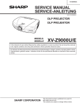
DIGITAL MULTIMEDIA PROJECTOR
DIGITALER MULTIMEDIA PROJEKTOR
PG-M20S
PG-M20X
MODELS
MODELLE
AN-60KT
In the interests of user-safety (Required by safety regulations in some countries) the set should be restored
to its original condition and only parts identical to those specified should be used.
Im lnteresse der Benutzersicherheit (erforderliche Sicherheitsregeln in einigen Ländern) muß das Gerät in seinen
Originalzustand gebracht werden. Außerdem dürfen für die spezifizierten Bauteile nur identische Teile verwendet
werden.
CONTENTS
INHALT
Page
» SPECIFICATIONS ............................................. 2
» IMPORTANT SERVICE SAFETY
NOTES (for USA) ............................................... 3
» NOTE TO SERVICE PERSONNEL ................... 4
» OPERATION MANUAL ...................................... 8
» REMOVING OF MAJOR PARTS ..................... 13
» RESETTING THE TOTAL LAMP TIMER ......... 19
» ELECTRICAL ADJUSTMENT ........................... 21
» TROUBLE SHOOTING TABLE ........................ 28
» CHASSIS LAYOUT .......................................... 94
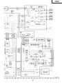
» BLOCK DIAGRAM ........................................... 96
» OVERALL WIRING DIAGRAM ........................ 98
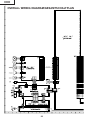
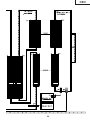
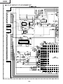
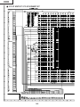
» SCHEMATIC DIAGRAM ................................ 100
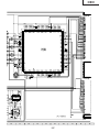
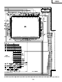
» PRINTED WIRING BOARD ASSEMBLIES ... 146
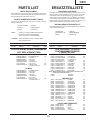
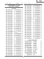
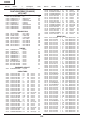
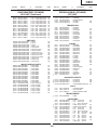
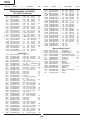
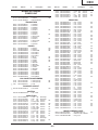
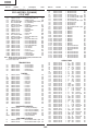
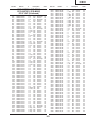
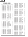
» PARTS LIST
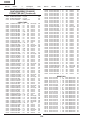
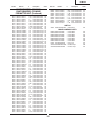
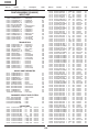
Ë ELECTRICAL PARTS ................................ 153
Ë CABINET AND MECHANICAL PARTS ..... 166
Ë ACCESSORIES PARTS ............................ 170
Ë PACKING PARTS ....................................... 170
» PACKING OF THE SET ................................. 171
» AN-60KT ........................................................ 172
SHARP CORPORATION
Seite
» TECHNISCHE DATEN ..................................... 49
» HINWEISE FÜR DAS
WARTUNGSPERSONAL ................................ 50
» BEDIENUNGSANLEITUNG ............................ 52
» ENTFERNEN DER HAUPTTEILE ................... 57
» RÜCKSTELLEN DES
LAMPENBETRIEBSZEIT-TIMERS .................. 63
» ELEKTRISCH EINSTELLUNG ........................ 66
» FEHLERSUCHTABELLE ................................. 73
» CHASSIS-ANORDNUNG ................................ 94
» BLOCKSCHALTBILD ....................................... 96
» GESAMTSCHALTPLAN .................................. 98
» SCHEMATISCHER SCHALTPLAN ................ 100
» LEITERPLATTENEINHEITEN ....................... 146
» ERSATZTEILLISTE
Ë ELEKTRISCHE BAUTEILE ....................... 153
Ë GEHÄUSE UND MECHANISCHE
BAUTEILE .................................................. 166
Ë ZUBEHÖRTEILE ....................................... 170
Ë VERPACKUNGSTEILE .............................. 170
» VERPACKEN DES GERÄTS ......................... 171
» AN-60KT ........................................................ 172
This document has been published to be used for
after sales service only.
The contents are subject to change without notice.
PG-M20S
PG-M20X
Specifications
Product type Digital Multimedia Projector
Model PG-M20X/PG-M20S
Video system NTSC 3.58/NTSC 4.43/PAL/PAL-M/PAL-N/PAL 60/SECAM/
DTV480I/DTV480P/DTV720P/DTV1080I
Display method Single Chip Digital Micromirror Device™ (DMD™) by Texas Instruments
DMD panel Panel size: 0.7" (17.8 mm), 1 chip XGA DMD(PG-M20X)/0.55"(14.0mm)",1 chip SVGA DMD(PG-M20S)
No. of dots: 786,432 dots (1,024 [H] × 768 [V])(PG-M20X)/480.000 dots (800[H] × 600[V])(PG-M20S)
Lens 1–1.2 × zoom lens, F1.75–2.04, f = 28.0–33.5 mm
Projection lamp High Intensity Discharge Lamp (HID Lamp), DC 210 W
Component input signal 29-pin connector
(INPUT1) DVI input signal: Digital 250–1,000 mV 50 Ω
Analog 0.7 Vp-p 75 Ω
Y: 1.0 Vp-p, sync negative, 75 Ω terminated
PB: 0.7 Vp-p, 75 Ω terminated
PR: 0.7 Vp-p, 75 Ω terminated
Horizontal resolution 700 TV lines (DTV720P)(PG-M20X)/500TV Lines (S-Video[NTSC3.58])(PG-M20S)
Computer RGB input signal 29-pin connector
(INPUT 1) RGB separate/sync on green type analog input: 0–0.7 Vp-p, positive, 75 Ω terminated
HORIZONTAL SYNC. SIGNAL: TTL level (positive/negative)
VERTICAL SYNC. SIGNAL: Same as above
S-video input signal 4-pin Mini DIN connector
(INPUT 2) Y (luminance signal): 1.0 Vp-p, sync negative, 75 Ω terminated
C (chrominance signal): Burst 0.286 Vp-p, 75 Ω terminated
Video input signal RCA connector: VIDEO, composite video, 1.0 Vp-p, sync negative, 75 Ω
(INPUT 3) terminated
Pixel clock 12–230 MHz(PG-20X)/12-120MHz(PG-M20S)
Vertical frequency 43–100 Hz
Horizontal frequency 15–126 kHz(PG-20X)/15-102kHz(PG-M20S)
Audio input signal ø3.5 mm MINIJACK: AUDIO, 0.5 Vrms, more than 47 kΩ (stereo)
Audio output 2.0 W (monaural)
Speaker system 4 cm × 3 cm
Rated voltage AC 100–240 V
Input current 3.2 A
Rated frequency 50/60 Hz
Power consumption 290 W
Power dissipation <1,090 BTU/hour
Operating temperature 41°F to 95°F (+5°C to +35°C)
Storage temperature –4°F to 140°F (–20°C to +60°C)
Cabinet Plastic
I/R carrier frequency 38 kHz
Dimensions (approx.) 8 5⁄8" × 3" × 11 15⁄16" (219 (W) × 76 (H) × 303 (D) mm) (main body only)
8 3⁄4" × 3 1⁄4" × 12 1⁄2" (223 (W) × 83 (H) × 318 (D) mm) (including adjustment feet
and projecting parts)
Weight (approx.) 5.8 lbs. (2.6 kg)
Supplied accessories Remote control, Two R-03 batteries, Power cord for U.S., Canada etc. (6', 1.8 m), Power
cord for Europe, except U.K. (6', 1.8 m), Power cord for U.K., Hong Kong and Singapore (6',
1.8 m), Power cord for Australia, New Zealand and Oceania (6', 1.8 m), DVI to 15-pin D-sub
cable (6', 1.8 m), USB cable (6', 1.8 m), Carrying case, Lens cap (attached), Lens cap
strap, Terminal cover (attached), CD-ROM, Operation manual, Quick reference guides
Replacement parts Lamp unit (Lamp/cage module) (BQC-PGM20X//1), Remote control (RRMCGA013WJSA),
Two R-03 batteries (“AAA” size, UM/SUM-4, HP-16, or similar), Power cord for U.S., Canada
etc. (QACCDA007WJPZ), Power cord for Europe, except U.K. (QACCV4002CEZZ), Power
cord for U.K., Hong Kong and Singapore (QACCB5024CENA[PG-M20X]/QACCBA012WJPZ
[PG-M20S]), New Power cord for Australia, Zealand and Oceania (QACCL3022CEZZ),
DVI to 15-pin D-sub cable (QCNWGA010WJZZ), USB cable (QCNWG0001WJPZ),
Carrying case (GCASN0005CESA), Lens cap (CCAPHA001WJ01), Lens cap strap
(UBNDT0013CEZZ),Terminal cover (GCOVD0103CESA), CD-ROM (UDSKA0058CEN1
[PG-M20X]/UDSKAA009WJZZ[PG-M20S]),Operation manual (TINS-7609CEZZ[PG-M20X]
/TINS-A209WJZZ[PG-M20S]), Quick reference guides
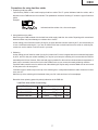
This SHARP projector uses a DMD panel. This very sophisticated panel contains 786,432(PG-M20X)/480,000(PG-M20S) pixels. As with any high tech nology electronic equipment
such as large screen TVs, video systems and video cameras,
there are certain acceptable tolerances that the equipment
must conform to.
This unit has some inactive pixels within acceptable tolerances which may result in inactive dots on the picture screen.
This will not affect the picture quality or the life expectancy
of the unit.
Specifications are subject to change without notice.
2
PG-M20S
PG-M20X
IMPORTANT SERVICE SAFETY NOTES (for USA)
Ë Service work should be performed only by qualified service technicians who are
thoroughly familiar with all safety checks and servicing guidelines as follows:
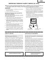
» Use an AC voltmeter with sensitivity of 5000 ohm
per volt., or higher, sensitivity to measure the AC
voltage drop across the resistor (See Diagram).
» All checks must be repeated with the AC plug
connection reversed. (If necessary, a non-polarized
adapter plug must be used only for the purpose of
completing these checks.)
Any reading of 0.3 volts RMS (this corresponds to
0.2 milliamp. AC.) or more is excessive and indicates
a potential shock hazard which must be corrected
before returning the unit to the owner.
WARNING
1. For continued safety, no modification of any circuit
should be attempted.
2. Disconnect AC power before servicing.
BEFORE RETURNING THE PROJECTOR:
(Fire & Shock Hazard)
Before returning the projector to the user, perform
the following safety checks:
1. Inspect lead wires are not pinched between the
chassis and other metal parts of the projector.
2. Inspect all protective devices such as non-metallic
control knobs, insulating materials, cabinet backs,
adjustment and compartment covers or shields,
isolation resistor-capacity networks, mechanical
insulators, etc.
3. To be sure that no shock hazard exists, check for
current leakage in the following manner:
» Plug the AC cord directly into a 120-volt AC outlet,
(Do not use an isolation transformer for this test).
» Using two clip leads, connect a 1.5k ohm, 10 watt
resistor paralleled by a 0.15µF capacitor in parallel
between all exposed metal cabinet parts and earth
ground.
AC
VOLTMETER
1.5k ohm (10W)
0.15µF
TEST PROBE
TO EXPOSED
METAL PARTS
CONNECT TO KNOWN
EARTH GROUND
12345678901234567890123456789012123456789012345678901234567890121234567890123456789012345678901212
12345678901234567890123456789012123456789012345678901234567890121234567890123456789012345678901212
12345678901234567890123456789012123456789012345678901234567890121234567890123456789012345678901212
SAFETY NOTICE
AVIS POUR LA SECURITE
Many electrical and mechanical parts in Projector have
special safety-related characteristics.
These characteristics are often not evident from visual
inspection, nor can protection afforded by them be
n e c e s s a r i l y i n c r e a s e d by u s i n g r e p l a c e m e n t
components rated for higher voltage, wattage, etc.
Replacement parts which have these special safety
characteristics are identified in this manual; electrical
components having such features are identified by “å”
and shaded areas in the Replacement Parts Lists and
Schematic Diagrams. For continued protection,
replacement parts must be identical to those used in
the original circuit. The use of a substitute replacement
parts which do not have the same safety characteristics
as the factory recommended replacement parts shown
in this service manual, may create shock, fire or other
hazards.
De nombreuses pièces, électriques et mécaniques, dans
les projecteur à présentent des caractéristiques
spéciales relatives à la sécurité, qui ne sont souvent
pas évidentes à vue.
Le degré de protection ne peut pas être nécessairement
augmentée en utilisant des pièces de remplacement
étalonnées pour haute tension, puissance, etc.
Les pièces de remplacement qui présentent ces
caractéristiques sont identifiées dans ce manuel;
les pièces électriques qui présentent ces particularités
sont identifiées par la marque “å” et hachurées dans
la liste des pièces de remplacement et les diagrammes
schématiques. Pour assurer la protection, ces pièces
doivent être identiques à celles utilisées dans le circuit
d’origine. L’utilisation de pièces qui n’ont pas les mêmes
caractéristiques que les pièces recommandées par
l’usine, indiquées dans ce manuel, peut provoquer des
électrocutions, incendies ou autres accidents.
WARNING: The bimetallic component has the primary
conductive side exposed. Be very careful in
handling this component when the power is on.
AVERTISSEMENT: La composante bimétallique dispose du
conducteur primaire dénudé. Faire
attention lors de la manipulation de cette
composante sous tension.
12345678901234567890123456789012123456789012345678901234567890121234567890123456789012345678901212
12345678901234567890123456789012123456789012345678901234567890121234567890123456789012345678901212
12345678901234567890123456789012123456789012345678901234567890121234567890123456789012345678901212
3
PG-M20S
PG-M20X
NOTE TO SERVICE
PERSONNEL
12345678901234567890123456789012123456789012345
12345678901234567890123456789012123456789012345
NOTE POUR LE PERSONNEL
D’ENTRETIEN
12345678901234567890123456789012123456789012345
UV-RADIATION PRECAUTION
12345678901234567890123456789012123456789012345
12345678901234567890123456789012123456789012345
PRECAUTION POUR LES RADIATIONS UV
12345678901234567890123456789012123456789012345
12345678901234567890123456789012123456789012345
The light source, metal halide lamp, in the projector
emits small amounts of UV-Radiation.
La source de lumière, la lampe métal halide,
dans le projecteur émet de petites quantités de
radiation UV.
AVOID DIRECT EYE AND SKIN EXPOSURE.
EVITEZ TOUTE EXPOSITION DIRECTE
DES YEUX ET DE LA PEAU.
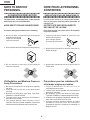
To ensure safety please adhere to the following:
Pour votre sécurité, nous vous prions de respecter
les points suivants:
1. Be sure to wear sun-glasses when servicing the
projector with the lamp
turned “on” and the top
enclosure removed.
1. Toujours porter des lunettes de soleil lors d’un
entretien du projecteur
avec la lampe allumée
et le haut du coffret retiré.
2. Do not operate the lamp outside of the lamp housing.
2. Ne pas faire fonctionner la lampe à l’extérieur du
boîtier de lampe.
3. Do not operate for more than 2 hours with the
enclosure removed.
3. Ne pas faire fonctionner plus de 2 heures avec le
coffret retiré.
UV-Radiation and Medium Pressure
Lamp Precautions
Précautions pour les radiations UV
et la lampe moyenne pression
1. Be sure to disconnect the AC plug when replacing
the lamp.
2. Allow one hour for the unit to cool down before
servicing.
3. Replace only with same type lamp. Type BQCPGM20X//1 rated 85V/210W.
4. The lamp emits small amounts of UV-Radiation,
avoid direct-eye contact.
5. The medium pressure lamp involves a risk of
explosion. Be sure to follow installation instructions
described below and handle the lamp with care.
1. To u j o u r s d é b ra n c h e r l a f i c h e AC l o r s d u
remplacement de la lampe.
2. Laisser l’unité refroidir pendant une heure avant de
procéder à l’entretien.
3. Ne remplacer qu’avec une lampe du même type.
Type BQC-PGM20X//1 caractéristique 85V/210W.
4. La lampe émet de petites quantités de radiation UVéviter tout contact direct avec les yeux.
5. La lampe moyenne pression implique un risque
d’explosion. Toujours suivre les instructions
d’installation décrites ci-dessous et manipuler la
lampe avec soin.
12345678901234567890123456789012123456789012345
4
PG-M20S
PG-M20X
12345678901234567890123456789012123456789012345
12345678901234567890123456789012123456789012345
12345678901234567890123456789012123456789012345
12345678901234567890123456789012123456789012345
1234567890123456789012345678901212345678901234
UV-RADIATION PRECAUTION (Continued)
1234567890123456789012345678901212345678901234
1234567890123456789012345678901212345678901234
PRECAUTION POUR LES RADIATIONS UV (Suite)
12345678901234567890123456789012123456789012345
12345678901234567890123456789012123456789012345
12345678901234567890123456789012123456789012345
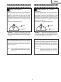
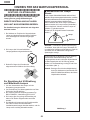
Lamp Replacement
Remplacement de la lampe
Note:
Remarque:
Since the lamp reaches a very high temperature
during units operation replacement of the lamp
should be done at least one hour after the power
has been turned off. (to allow the lamp to cool off.)
Installing the new lamp, make sure not to touch the
lamp (bulb) replace the lamp by holding its reflector
2.
[Use original replacement only.]
Comme la lampe devient très chaude pendant le
fonctionnement de l’unité, son remplacement ne doit
être effectué au moins une heure après avoir coupé
l’alimentation (pour permettre à la lampe de refroidir).
En installant la nouvelle lampe, s’assurer de ne pas
toucher la lampe (ampoule). Remplacer la lampe en
tenant son réflecteur 2.
[N’utiliser qu’un remplacement d’origine.]
1 Lampe
1 Lamp
2 Reflecteur
2 Reflector
DANGER ! –– Never turn the power on without the
lamp to avoid electric-shock or damage of the
devices since the stabilizer generates high voltages
at its start.
DANGER ! –– Ne jamais mettre sous tension sans
la lampe pour éviter un choc électrique ou des
dommages des appareils car le stabilisateur génère
de hautes tensions à sa mise en route.
Since small amounts of UV-Radiation are emitted
from an opening between the duct cover and the
lamp housing, it is recommended to place the LENS
CAP on the opening during servicing to avoid eye
and skin exposure.
Comme de petites quantités de radiation UV sont
émises par une ouverture entre le couvercle du conduit et le botier de la lampe,il est recommandé de
placer le CAPUCHON D'OPTIQUE sur l'ouverture
pendant l'entretien pour éviter une exposition des
yeux et la peau.
Note: Please obtain a lens cap before servicing a
models PG-M20X/PG-M20S that is received
without one.
Remarque: Priére de se procurer un capuchon
d'optique acant d'entretien un modéle
PG-M20X/PG-M20S qui est livré sans.
5
PG-M20S
PG-M20X
WARNING:
High brightness light source, do not stare into the beam of light, or view directly. Be especially
careful that children do not stare directly in to the beam of light.
WARNING:
TO REDUCE THE RISK OF FIRE OR ELECTRIC SHOCK, DO NOT EXPOSE THIS UNIT TO
MOISTURE OR WET LOCATIONS.
CAUTION
The lighting flash with arrowhead within
a triangle is intended to tell the user that
parts inside the product are risk of electric
shock to persons.
RISK OF ELECTRIC SHOCK.
DO NOT REMOVE SCREWS
EXCEPT SPECIFIED USER
SERVICE SCREWS
CAUTION: TO REDUCE THE RISK OF ELECTRIC SHOCK,
DO NOT REMOVE CABINET.
NO USER-SERVICEABLE PARTS EXCEPT LAMP UNIT.
REFER SERVICING TO QUALIFIED SERVICE
PERSONNEL.
The exclamation point within a triangle is
intended to tell the user that important
operating and servicing instructions are
in the manual with the projector.
12345678901234567890123456789012123456789012345678901234567890121234567890123456789012345678901212
12345678901234567890123456789012123456789012345678901234567890121234567890123456789012345678901212
AVERTISSEMENT: Source lumineuse de grande intensité. Ne pas fixer le faisceau lumineux ou le regarder
directement. Veiller particulièrement à éviter que les enfants ne fixent directement le
faisceau lumineux.
AVERTISSEMENT: AFIN D’EVITER TOUT RISQUE D’INCENDIE OU D’ELECTROCUTION, NE PAS PLACER
CET APPAREIL DANS UN ENDROIT HUMIDE OU MOUILLE.
ATTENTION
L’éclair terminé d’une flèche à l’intérieur
d’un triangle indique à l’utilisateur que les
pi‘eces se trouvant dans l’appareil sont
susceptibles de provoquer une décharge
électrique.
RISQUE
D’ELECTROCUTION NE
PASRETIRER LES VIS, A
L’EXCEPTION DES VIS DE
REPARATION UTILISATEUR
SPECIFIEES
Le point d’exclamation à l’intérieur d’un
triangle indique à l’utilisateur que les
instr uctions de fonctionnement et
d’entretien sont détaillées dans les
documents fournis avec le projecteur.
ATTENTION: POUR EVITER TOUT RISQUE
D’ELECTROCUTION, NE PAS RETIRER LE CAPOT.
AUCUNE DES PIECES INTERIEURES N’EST REPARABLE
PAR L’UTILISATEUR, A L’EXCEPTION DE L’UNITE DE
LAMPE. POUR TOUTE REPARATION, S’ADRESSER A UN
TECHNICIEN D’ENTRETIEN QUALIFIE.
6
PG-M20S
PG-M20X
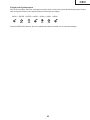
Precautions for using lead-free solder
1 Employing lead-free solder
"Input and key PWBs" of this model employs lead-free solder. The LF symbol indicates lead-free solder, and is
attached on the PWBs and service manuals. The alphabetical character following LF shows the type of lead-free
solder.
Example:
LFa
Indicates lead-free solder of tin, silver and copper.
2 Using lead-free wire solder
When fixing the PWB soldered with the lead-free solder, apply lead-free wire solder. Repairing with conventional
lead wire solder may cause damage or accident due to cracks.
As the melting point of lead-free solder (Sn-Ag-Cu) is higher than the lead wire solder by 40°C, we recommend you
to use a dedicated soldering bit, if you are not familiar with how to obtain lead-free wire solder or soldening bit,
contact our service station or service ranch in your area.
3 Soldering
As the melting point of lead-free solder (Sn-Ag-Cu) is about 220°C which is higher than the conventional lead solder
by 40°C, and as it has poor solder wettabillty, you may be apt to keep the soldering bit in contact with the PWB for
extended period of time. However, Since the land may be peeled off or the maximum heat-resistance temperature of
parts may be excoeded, remove the bit from the PWB as soon as you conurm the steady soldering condition.
Lead-free solder contains more tin, and the end of the soldering bit may be easily corroded. Make sure to tum on and
off the power of the bit as required.
if a different type of solder stays on the tip of the soldering bit, it is alloyed with lead-free solder. Clean the bit after
every use of it.
When the tip of the soldering bit is blackened during use, file it with steel wool or fine sandpaper.
Becareful when replacing parts with polarity indication on the PWB silk.
Lead-free wire solder for servicing
Part No.
ZHNDAi123250E
ZHNDAi126500E
ZHNDAi12801KE
★
J
J
J
Description
φ0.3mm
250g(1roll)
φ0.6mm
500g(1roll)
φ1.0mm
1kg(1roll)
7
Code
BL
BK
BM
PG-M20S
PG-M20X
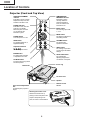
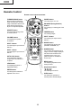
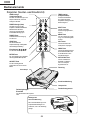
Location of Controls
Projector (Front and Top View)
LAMP REPLACEMENT
indicator
TEMPERATURE
WARNING indicator
Illuminates in green normally.
Replace the lamp when the
indicator illuminates in red.
Illuminates in green
normally. When the
internal temperature
rises, this indicator will
illuminate in red.
POWER indicator
Illuminates in red, when the
projector is in standby.
When the power is turned
on, this indicator will
illuminate in green.
INPUT button
For switching input mode
1, 2 or 3.
MENU button
Turns the power on or off.
For displaying adjustment
and setting screens.
LENS button
VOLUME buttons
For adjusting Keystone or
Digital Shift setting.
For adjusting the
speaker sound level.
Adjustment buttons
(
)
UNDO button
POWER button
For undoing an operation
or returning to the default
settings.
For selecting menu items.
ENTER button
AUTO SYNC button
For setting items selected
or adjusted on the menu.
For automatically
adjusting images when
connected to a computer.
AV MUTE button
For temporarily turning off the
sound and picture.
Focus ring
Zoom knob
Terminal cover
Speaker
Remote control
sensor
Foot releases/Adjustment
feet
For adjusting the projector’s
height.
Attaching the terminal cover
Attach the terminal cover by
placing it on the side panel of the
projector and pressing it into
place, as shown in the illustration.
8
PG-M20S
PG-M20X
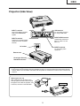
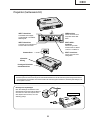
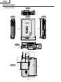
Projector (Side View)
INPUT 1 terminal
USB terminal
Port for DVI digital, computer
RGB, and COMPONENT
signals.
For connecting a computer using a USB cable.
INPUT 2 terminal
INPUT AUDIO terminal
Shared audio terminal for
INPUT 1, INPUT 2, and
INPUT 3.
Terminal for connecting video
equipment with an S-VIDEO
terminal.
AC socket
INPUT 3 terminal
For connecting video
equipment.
Exhaust vent
Kensington Security
Standard connector
Using the Kensington Lock
• This projector has a Kensington Security Standard connector for use with a Kensington MicroSaver Security
System. Refer to the information that came with the system for instructions on how to use it to secure the
projector.
Attaching the lens cap
After putting the lens cap strap on the
lens cap, pass the other end of the strap
through the hole under the projector, next
to the lens, as shown in the illustration.
Bottom View
9
PG-M20S
PG-M20X
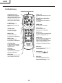
Remote Control
Remote control signal transmitter
FORWARD/BACK button
POWER button
Moves forward or backwards
when connected to a computer
using a USB cable. Same as the
[Page Down] and [Page Up]
keys on a computer keyboard.
Turns the power on or off.
ENLARGE (Enlarge/Reduce)
buttons
For enlarging or reducing part of the
image.
AV MUTE button
For temporarily turning off the
sound and picture.
FREEZE button
For freezing images.
INPUT 3 button
VOLUME buttons
For switching the input mode to
INPUT 3.
For adjusting the speaker
sound level.
RESIZE button
INPUT 2 button
For switching the screen size
(NORMAL, BORDER, etc).
For switching the input mode to
INPUT 2.
GAMMA button
INPUT 1 button
For correcting the brightness of an
image, when the images displayed
are hard to see because of the
brightness of the room. Four
gamma modes are available to
choose from.
For switching the input mode to
INPUT 1.
AUTO SYNC button
For automatically adjusting
images when connected to a
computer.
MENU button
For displaying adjustment and
setting screens.
LENS button
For adjusting Keystone or
Digital Shift setting.
Adjustment buttons
(
)
ENTER button
For selecting menu items.
For setting items selected or
adjusted on the menu.
UNDO button
For undoing an operation or
returning to the default settings.
10
PG-M20S
PG-M20X
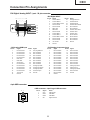
Connection Pin Assignments
DVI Digital / Analog INPUT 1 port : 29 pin connector
• DVI Digital INPUT
9
•••••••••
1 2
••••
Pin No.
1
2
3
4
5
6
7
8
9
10
11
12
13
14
15
~ • • • • • • • • • 16
~ •••• 7 8
C1
C2
C4
C5
C3
17
24
18
••••
~
••••
23
• DVI Analog RGB Input
Pin No.
1
2
3
4
5
6
7
8
9
10
11
12
13
14
15
Signal
Not connected
Not connected
Not connected
Not connected
Not connected
DDC clock
DDC data
Vertical sync
Not connected
Not connected
Not connected
Not connected
Not connected
+5V current
Ground
Signal
T.M.D.S data 2–
T.M.D.S data 2+
T.M.D.S data 2 shield
Not connected
Not connected
DDC clock
DDC data
Not connected
T.M.D.S data 1–
T.M.D.S data 1+
T.M.D.S data 1 shield
Not connected
Not connected
+5V current
Ground
Pin No.
16
17
18
19
20
21
22
23
24
C1
C2
C3
C4
C5
• DVI Analog Component Input
Pin No.
16
17
18
19
20
21
22
23
24
C1
C2
C3
C4
C5
Signal
Hot plug detection
Not connected
Not connected
Not connected
Not connected
Not connected
Not connected
Not connected
Not connected
Analog input Red
Analog input Green
Analog input Blue
Horizontal sync
Ground
Pin No.
1
2
3
4
5
6
7
8
9
10
11
12
13
14
15
Signal
Not connected
Not connected
Not connected
Not connected
Not connected
Not connected
Not connected
Not connected
Not connected
Not connected
Not connected
Not connected
Not connected
Not connected
Ground
Pin No.
16
17
18
19
20
21
22
23
24
C1
C2
C3
C4
C5
4-pin USB connector
• USB connector: 4 pin B-type USB connector
2
1
3
4
Signal
Hot plug detection
T.M.D.S data 0–
T.M.D.S data 0+
T.M.D.S data 0 shield
Not connected
Not connected
T.M.D.S clock shield
T.M.D.S clock+
T.M.D.S clock–
Not connected
Not connected
Not connected
Not connected
Ground
Pin no.
1
2
3
4
Signal
VCC
USB–
USB+
SG
Name
USB current
USB data–
USB data+
Signal Ground
11
Signal
Not connected
Not connected
Not connected
Not connected
Not connected
Not connected
Not connected
Not connected
Not connected
Analog input Pr/Cr
Analog input Y
Analog input Pb/Cb
Not connected
Ground
PG-M20S
PG-M20X
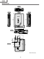
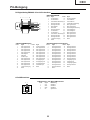
Dimensions
Rear View
Side View
Top View
12 9/16
(318.3)
Side View
11 15/16
(303)
8 3/4 (223)
8 5/8 (219)
5 1/16 (128)
Front View
1 1/2
3 1/4
3
(38.7) (76.1) (82.9)
3/8
1
(34.2)
4 9/16 (115.5)
7 11/16 (195)
3 1/4 (82.5)
3/16
2
(55.5)
3 1/ 8
(80)
Bottom View
2 3/8
(60)
5/16
(7.5)
4 1/ 8
(104)
10 5/16
(261.5)
Units: inches (mm)
12
PG-M20S
PG-M20X
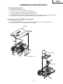
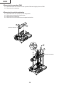
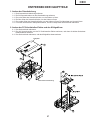
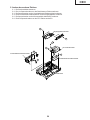
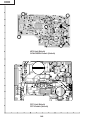
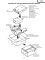
REMOVING OF MAJOR PARTS
1. Removing the top panel
1-1.
1-2.
1-3.
1-4.
1-5.
1-6.
Detach the terminal block cover.
Remove the five lock screws from the top panel.
Press the right side of the bottom body to undo the hook.
Press the left side of the bottom body to undo the hook.
Press the front of the bottom body to undo the hook. Get the top panel loose from the bottom body.
Slightly raise the front of the top panel and disconnect the speaker connector.
2. Removing the PC I/F PWB and cooling fan
2-1. Disconnect the connector.
2-2. Remove the three lock screws from the PC I/F PWB and then the two hex support screws.
2-3. Disconnect the connector and take out the cooling fan.
Top panel
1-2
1-2
1-6
1-4
1-3
1-2
2-2
1-1
2-1
1-5
1-2
PC I/F PWB unit
1-2
Terminal block cover
2-3
2-3
Cooling fan
2-2
13
PG-M20S
PG-M20X
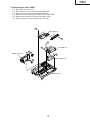
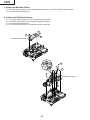
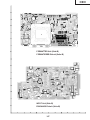
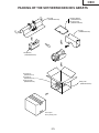
3. Removing the operation PWB
3-1. Remove the two lock screws from the operation PWB and slightly raise this PWB.
3-2. Disconnect the connectors.
4. Removing the optical mechanism
4-1.
4-2.
4-3.
4-4.
Remove the two lock screws from the lamp socket.
Raise the two lamp socket lead fixtures.
Disconnect the connectors.
Remove the six lock screws from the optical mechanism.
3-2
3-1
3-1
Operation PWB unit
4-1
4-2
4-4
Optical mechanism
4-3
14
PG-M20S
PG-M20X
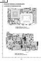
5. Removing the other PWBs
5-1.
5-2.
5-3.
5-4.
5-5.
5-6.
Disconnect the connectors.
Remove the four lock screws from the power PWB.
Remove the lock screw from the ballast PWB unit.
Remove the three hex support screws from the input PWB.
Remove the lock screw from the terminal block cover.
Remove the three lock screws from the PFC PWB.
5-4
Input PWB unit
5-5
5-2
5-1
PFC PWB unit
5-3
Ballast PWB unit
5-1
5-6
Power PWB unit
5-1
Bottom body
15
PG-M20S
PG-M20X
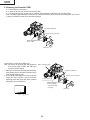
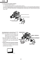
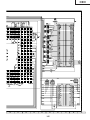
6. Removing the formatter PWB
6-1. Disconnect the connector.
6-2. Remove the two lock screws from the heat sink.
6-3. Remove the four lock screws from the backer plate assembly, and detach the formatter PWB.
Note: The DMD (Digital Micromirror Device) unit is easily affected by static electricity. In handling this unit, be sure
to wear a wristband or take other anti-static measure.
Formatter PWB unit
6-1
Backer plate assembly
6-3
DMD (Digital Micromirror
Device) unit
Heat sink
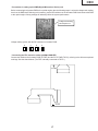
Precautions in replacing the DMD chip
Note: Be careful not to allow dust and fingerprint
on the cover glass of DMD chip and prism
surface of optical engine.
1. When you fix 4screws of backer plate assembly,
press backer plate to formatter PWB and fix by
cross multiply step by step.
2. If something shade appears on the projection
screen like Fig1, release 2 screws on mirror
adjusting plate and move that plate to adjust
illumination area of DMD chip.
6-2
Mirror adjusting plate
Formatter PWB unit
Backer plate assembly
Prism surface
DMD (Digital Micromirror
Device) chip
+Outer Frame
+C-spring
Heat sink
Fig.1
Shade
16
PG-M20S
PG-M20X
* Precautions in setting up the DMD (Digital Micromirror Device) unit
Before connecting the formatter PWB to the optical engine, take the following steps. Look at the voltage rank marking
that is on the DMD itself. Referring to this marking, set the DIP switches on the formatter PWB. And connect this PWB
to the optical engine. Wrong settings will adversely affect the system performance.
Voltage rank marking
This sample is "C".
Voltage ranking system with the DIP switches on formatter PWB
B
C
D
E
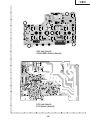
* Connecting the FPC extension cables (QCNW-A298WJZZ)
Connect the cables to the formatter PWB (TO FMT) and the PC I/F PWB (TO PC), referring to the silk-screen-printed
markings. See the sketch below. (The FPC is already connected at TO PC.)
TO FMT
TO PC
17
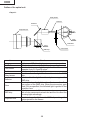
PG-M20S
PG-M20X
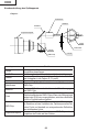
Outline of the optical unit
<Layout>
Relay lenses
Rod lens
Reflector
Projection lens
Lamp
UV/IR filter
Prism
DMD chip
Item
Lamp
UV/IR filter
Color wheel
Rod lens
Relay lenses
Reflector
Prism
DMD chip
Projection lens
Color wheel
Function
Light source. DC-driven high-pressure mercury vapor lamp.
Used to absorb ultraviolet and infrared rays.
Used to let the source light through the color filter and to
separate it into R, G and B colors.
Used to make for uniform light beams.
Used to collect the light from the rod lens into the DMD
chip.
Used to reflect the light from the relay lenses against the
DMD chip.
Used to introduce the light from the reflector over the effective surface of the DMD chip. When the micromirror gets
tilted (ON) as specified, the reflected light is guided to the
projection lens.
Used to turn on and off the micromirror in response to the
ratio of color components at each dot and thus to reflect the
incoming light accordingly.
Used to enlarge the light from the DMD chip and to get the
light projected on the screen.
18
PG-M20S
PG-M20X
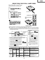
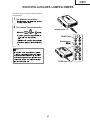
RESETTING THE TOTAL LAMP TIMER
Resetting the Lamp Timer
Reset the lamp timer after replacing the lamp.
1
Connect the power cord.
• Plug the power cord into the AC socket
of the projector.
2
AC socket
Reset the lamp timer.
• While
pressing
,
, and
tor, press
simultaneously
on the projec-
POWER button
on the projector.
• ÒLAMP 0000HÓ is displayed, indicating
Adjustment buttons
( |)
that the lamp timer is reset.
|
Info
• Make
sure to reset the lamp timer only
when replacing the lamp. If you reset the
lamp timer and continue to use the same
lamp, this may cause the lamp to become
damaged or explode.
ENTER button
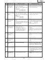
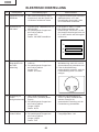
■ The warning lights on the projector indicate problems inside the projector.
■ If a problem occurs, either the TEMPERATURE WARNING indicator or the LAMP REPLACEMENT
indicator will illuminate red, and the power will turn off. After the power has been turned off, follow
the procedures given below.
TEMPERATURE
WARNING
indicator
POWER
indicator
LAMP
REPLACEMENT
indicator
About the TEMPERATURE WARNING indicator
If the temperature inside the projector increases, due to blockage of the air vents, or
will blink in the
the setting location,
lower left corner of the picture. If the temperature keeps on rising, the lamp will turn
off and the TEMPERATURE WARNING indicator will blink, the cooling fan will run for
further 90 seconds, then the power will be
shut off. After
appears, be sure to
perform the following measures.
About the
LAMP
REPLACEMENT
indicator
■ When the lamp
exceeds 1,900 cumulative hours
will be displayed
of use,
on the screen in yellow. When
the cumulative hours of use
reach 2,000,
will
change to red, the lamp will automatically turn off and then the
projector as well. At this time, the
LAMP REPLACEMENT indicator will illuminate in red.
■ If you try to turn on the projector
a fourth time without replacing
the lamp, the projector will not
turn on.
Maintenance indicator
Condition
Problem
Possible Solution
Abnormal
Normal
•
Relocate
the projector to an area
• Blocked air intake
with proper ventilation.
TEMPERAThe internal
TURE
• Take the projector to your nearest
• Cooling fan breaktemperature is
Red on/
WARNING
Off
Sharp Authorized Projector Dealer
down
Power off abnormally high.
indicator
• Internal circuit failure or Service Center for repair.
• Clogged air intake
LAMP
REPLACEMENT
indicator
Green on
Green
blinks
when the
lamp is
active.
Red
blinks
Time to change
the lamp
• Lamp usage time
exceeded 1,900
hours
Red on/
Power off
The lamp does
not illuminate.
• Burnt-out lamp
• Lamp circuit failure
19
• Take the projector to your nearest
Sharp Authorized Projector Dealer
or Service Center for repair or
lamp replacement.
• Please exercise care when
replacing the lamp.
PG-M20S
PG-M20X
How to Release the System Lock
Turn on the power. If the system lock is applied, the system-resetting screen appears. Press the following keys in this
order.
MENU → ENTER → ENTER → MENU → UNDO → UNDO → MENU
After pressing the MENU key first, press the remaining six keys within 10 seconds.
20
PG-M20S
PG-M20X
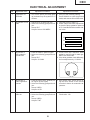
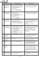
ELECTRICAL ADJUSTMENT
No.
Adjustment Items
Adjustment Conditions
Adjustment Procedures
1
Initialization of
EEPROM
1. Turn on the power (the lamp lights
up) and warm up the system for 15
minutes.
1. Carry out the following setting.
Press SW2001 to enter the process
mode, and execute S2 on SSS menu.
2
Adjustment of CW
index
1. Signal input: 64-step color bar
2. Select the following group and subject.
Group: DLP
Subject: Select CW-INDEX.
1. Feed the signal to INPUT 1.
2. Select subject and make adjustment
so that the lamp gradation patterns
of R, G and B should be smooth without noise.
R
G
B
3
Adjustment of
RGB gradation
reproduction
1. Feed the SMPTE pattern signal.
2. Select the following group and subject.
Group: DLP
Subject: G1-GAIN
1. Confirm that 100% and 95% white
gradation, and 0% and 5% black gradation are discernible.
2. If the white gradation looks differently,
do fine adjustment by G1-GAIN.
4
Adjustment of
video brightness/
contrast
1. Feed the NTSC100% window patter signal. (Burst signal)
2. Select the following group and subject.
Group: VIDEO
Subject: AUTO
1. After signal input, select AUTO using the set's switch or the remote
controller's button for automatic adjustment.
5
Adjustment of
video tint
1. Feed the split color bar signal.
2. Select the following group and subject.
Group: VIDEO
Subject: TINT
1. Confirm the fixed value.
Fixed value: 128
21
PG-M20S
PG-M20X
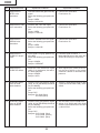
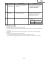
No.
Adjustment Items
Adjustment Conditions
Adjustment Procedures
6
Adjustment of
NTSC color
saturation
1. Feed the internal 8ch (split color bar)
signal.
2. Select the following group and subject.
Group: VIDEO
Subject: N-COLOR
1. Confirm the fixed value.
Fixed value: 59
7
Adjustment of PAL 1. Feed the PAL color bar signal.
color saturation
2. Select the following group and subject.
Group: VIDEO
Subject: P-COLOR
1. Confirm the fixed value.
Fixed value: 59
8
Adjustment of
SECAM color
saturation
1. Feed the SECAM color bar signal.
2. Select the following group and subject.
Group: VIDEO
Subject: S-COLOR
1. Confirm the fixed value.
Fixed value: 59
9
Adjustment of
COMPO G brightness
1. Input signal: 0% gray pattern signal (480I)
2. Select the following group and subject.
Group: COMPO
Subject: G-BRIGHT
1. Feed the signal to INPUT 1.
Make adjustment so that some bits
should be missing in the picture.
10
Adjustment of
COMP CR-Offset
1. Feed the color difference signal
(480I): Y 0% brightness, Cb and Cr
0% white patterns.
Group: COMPO
Subject: AUTO
1. After signal input, select AUTO using the set's switch or the remote
controller's button for automatic adjustment.
11
Automatic Adjustment of RGB
white balance
1. Feed the 50% gray pattern signal
(XGA, 60 Hz [PG-M20X]/SVGA,60
Hz [PG-M20S]).
2. Select the following group and subject.
Group: DLP
Subjects: R1-GAIN (Red)
B1-GAIN (Blue)
1. Adjust R-1 GAIN and B1-GAIN so that
x-value should be 266±3 and y-value
320±3.
12
Automatic Adjustment of SRGB
white balance
1. Feed the 50% gray pattern signal
(XGA, 60 Hz [PG-M20X]/SVGA,60
Hz [PG-M20S]).
2. Select the following group and subject.
Group: DLP
Subjects: S-R1-GAIN (Red)
S-G1-GAIN (Green)
S-B1-GAIN (Blue)
1. Set the value of S-R1-GAIN to 34.
2. Adjust S-G1-GAIN and S-B1-GAIN
so that x-value should be 310±3 and
y-value 335±3.
22
PG-M20S
PG-M20X
No.
Adjustment Items
Adjustment Conditions
Adjustment Procedures
13
Automatic adjustment of video
white balance
1. Feed the 50% gray pattern signal
(NTSC, burst signal).
2. Select the following group and subject.
Group: DLP
Subjects: V-R1-GAIN (Red)
V-B1-GAIN (Blue)
1. Adjust V-R1-GAIN and V-B1-GAIN so
that x-value should be 265±3 and yvalue should be 298±3.
14
Automatic adjust- 1. Feed the 50% gray pattern signal
ment of DTV white
(480I, color difference signal).
balance
2. Select the following group and subject.
Group: DLP
Subjects: C-R1-GAIN
C-B1-GAIN
1. Adjust C-R1-GAIN and C-B1-GAIN
so that x-value should be 263±3 and
y-value should be 295±3.
15
Adjustment of
DLP voltage (For
reference)
1. Read voltage rank of DLP description.
2. Set the switch corresponding to the
rank which has been read. (on the
formatter PWB)
1. Carry out adjustment when DLP chip
has been replaced or combination of
chip and formatter has been changed.
2. Rank:
B C D E
Setting value: 1 2 3 4
16
Confirmation and
re-adjustment of
white balance
1. The adjusting conditions for each
item are as follows:
For RGB input, see Item 11
For SRGB input, see Item 13
For video input, see Item 14
For DVT input, see Item 12
Confirm that there is no deviation in white
balance from that of the monitoring
equipment.
For readjustment, proceed in the order
of RGB input, video input and DTV input.
17
Confirmation of
color-related
operation
1. Receive the color bar signal.
1. Select L1 in the process mode.
Check the performance of color and
tint.
18
Confirmation of
picture-related
operation
1. Receive monoscope pattern signal.
1. Select L2 in the process mode.
Check Picture, Brightness and Sharpness.
19
Confirmation of
RGB
1. Receive the RGB signal.
1. Select L4 on the process mode.
Check Picture, Brightness, Red, Blue,
Clock, Phase, H-POS and V-POS.
20
Confirmation of
off-timer operation
21
Confirmation of
thermistor operation
1. Select OFF in the process mode.
Confirm that the off-timer starts with
5-minute display, counts 1 minute for
1 second, and turns off when 0 minute
is displayed.
1. Heat the thermistor by dryer.
23
1. Confirm that the temperature is displayed.
PG-M20S
PG-M20X
No.
Adjustment Items
Adjustment Conditions
Adjustment Procedures
22
Automatic sync
operation
1. Receive the phase checking pattern
signal.
1. Confirm that Clock, Phase, H-POS
and V-POS can be automatically
adjusted in the VGA/S-VGA/XGA
mode.
23
Confirmation of
USB operation
Connect the set to a personal computer
by USB cable.
Using the remote controller, make sure
that feed and return operations are effective on the display of the personal
computer.
24
Factory settings
1. Make the following settings.
Process
adjustment
S4
Remote controller
settings
"Factory Setting 4"
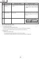
How to Adjust the PC I/F unit
1. Initialization of EEPROM
1) Press SW2002 to enter the process mode.
2) Execute S1 on the SSS menu. (By S1, all the contents of EEPROM are initialized.)
3) Confirm that the program version "Ver. XXX" has become the latest one
2. Adjusting items
1) Adjustment of RGB drive/gain
(1) feed the window pattern signal that has 100% and 0% signals.
(2) Select AUTO among the A/D items in the process mode and carry out adjustment.
24
PG-M20S
PG-M20X
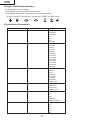
» Entering the adjustment process mode
There are follwing two methods.
» Press the SW2001 on the KEY PWB unit.
» Press the follwing keys in this order.
AV MUTE→AV MUTE→Adj up→Adj down→ENTER→ENTER→MENU
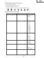
» Adjustment mode process menu
Group
Adjust PC Image
A/D
Sub Group
Adjust DLP Image
DLP
Adjust VIDEO Image
VIDEO
Adjust Component Image
DTV
Process mode
LINE
INTIAL SETTING
SSS
25
Subject
R-BRIGHT
G-BRIGHT
B-BRIGHT
R-D
B-D
G-D
AD-AUTO
R1-BLK
R1-GAIN
G1-BLK
G1-GAIN
B1-GAIN
CW-INDEX
S-R1-GAIN
S-G1-GAIN
S-B1-GAIN
C-R1-GAIN
C-B1-GAIN
V-R1-GAIN
V-B1-GAIN
PICTURE
BRIGHT
TINT
N-COLOR
P-COLOR
S-COLOR
STAT-GAIN
VIDEO-AUTO
G-BRIGHT
CB-OFFSET
CR-OFFSET
COMPO-AUTO
L1
L2
L3
OFF
TEMP OFF
SENSOR CHECK
TIME
S1
S2
S3
S4
S5
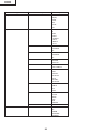
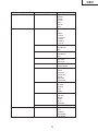
PG-M20S
PG-M20X
Group
Sample Pattern
PATTERN
Sub Group
Adjust CVIC
CVIC-PROGRSSIVE
Subject
RGB
RGB(50)
CROSS
FOCUS
SETP
COLOR
CHR
MODE
IP
MDSW
PTGSW
C-TESTSW
C-ILG-LY
C-MOD-LY
C-VE-LV
ENH-PLUS
ENH-MINUS
DFC
ENH-PLUS
ENH-MINUS
DFC
MODE
ENH-GAIN
ENH-PLUS
CUBIC-RGB
CUBIC-VEDEO
YNR-LEVEL
YNR-K
YNR-FSEL
CNR-LEVEL
CNR-K
CNR-FSEL
CNR-FILSW
TESTSW
ENABLE
MV-F
VDDTP
RED
YELLOW
GREEN
CYAN
BLUE
MAGENTA
TABLE
IPL
IPL2
E2PROM
ADR RD/WR
USB-MODE
CVIC-ENHANCE-VIDE
CVIC-ENHANCE-HTTV
CVIC-ENHANCE-RGB
CVIC-SCREEN
CVIC-NR
CVIC-PTG
CVIC-CMS
Version Check etc
CVIC-DEGAMMA
Special
26
PG-M20S
PG-M20X
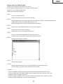
How to write in a Serial number
Install the new program for the software into your PC
a.This software is downloaded from home page of SHARP intranet.
http://172.24.145.13/tcg-qrc/prj/prj-e.asp
NAME:USB to Sirial Driver program.
STEP 1
Set-up for USB Serial Driver
(Refer to "Installation Process and advice.doc" file.)
STEP 2
Call the adjustment process mode, and select the sub-group "SPECIAL" and the adjustment item
"USB-MODE". Change the USB MODE value from 0 to 1.
(With this change, input of a 232C command becomes possible.)
STEP 3
Please connect the USB cable between the PC and the projector.
STEP 4
Please execute the program "TeraTerm".
(configuration file is to use attached Teraterm.ini.)
STEP 5
You write it by using the attached macro-file (serial_write.ttl).
A serial number is described in this macro-file. Enter this number.
STEP 6
Message will be appear as follows,
STEP 7
Please finish TeraTerm.
STEP 8
Please change the value from 1 to 0 for USB MODE in Special (Factory mode).
(For this change, input of a 232C command becomes invalid.)
<Attention >
After the installation for USB to 232C driver, select the 232C with SW2002 on the KEY unit.
Connect the USB cable, and change COM2 for teraterm(setup-serial port) then push "Enter" key
and confirm "ERR" message comes back.
If "ERR" comes back setting is correct. In case of "ERR" does not come back, COM2 is incorrect.
Please try COM3, COM4 by turn, and find correct COM port.
27
PG-M20S
PG-M20X
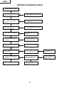
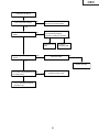
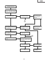
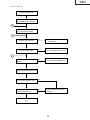
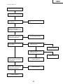
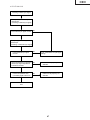
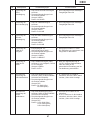
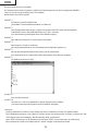
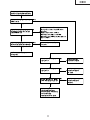
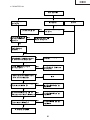
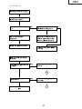
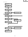
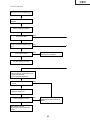
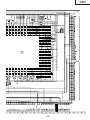
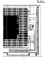
TROUBLE SHOOTING TABLE
Checking of Basic Operation
Does the POWER LED light up or
flicker in red or green?
No
Go to "Checking of Power Unit".
Yes
Does the set operate by the set's
key or the remote controller's
power key?
No
Go to "Checking of Sub-microcomputer
and Its Periphery"
Yes
Does the cooling fan rotate and
does the lamp light up?
No
Go to "Checking of Lamp Lighting-up"
Yes
Is the user menu displayed?
No
Check the formatter circuit and
its periphery.
No
Check IC8013 (AD) and go to
"Checking of RGB Input".
No
Check IC8015 and peripheral
circuit.
No
Is there input signal at pins
(8), (17) and (23) of IC8013?
No
Check IC3852 and its
peripheral circuit.
No
Go to "Checking of Video
Input". Is there input signal at
the emitter of Q8002?
No
Check IC3852 and its
peripheral circuit.
Yes
Does the RGB input operate
normally?
Yes
Does the video input operate
normally?
Yes
Do the component input/DVI input
operate normally?
Yes
Does the DVI input operate
normally?
Yes
End
Yes
Check IC8015 and its
peripheral circuit.
28
PG-M20S
PG-M20X
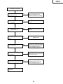
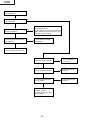
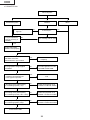
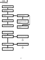
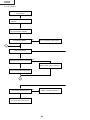
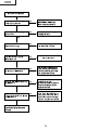
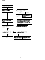
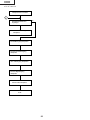
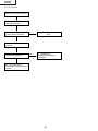
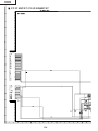
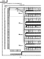
Checking of Power Unit
Are connectors in the power unit
completely inserted?
No
Insert the connectors CN702,
CN704, CN7003, CN7001,
CN7004 and CN7101 completely.
No
Close the lamp door completely by
screws.
No
Replace the fuse as well as its
harness.
Yes
Is the lamp door closed
completely?
Yes
Does the temperature
fuse function?
Yes
Is AC voltage applied across relay
RL701?
No
Replace F701.
Yes
Is there DC voltage of about 6V at
pin (1) of CN7002?
No
Check Q7501, Q7502 and Q7503
and their peripheral circuits. If any
circuit is damaged, replace it.
No
Check the circuits connected to the
primary side of T701. If any circuit
is damaged, replace it.
No
Check the circuits connected to the
secondary side of T701. If any
circuit is damaged, replace it.
Yes
Is there DC voltage of about 370V
across CN702?
Yes
Is there rated voltage at the output
terminals of CN702 and CN7102?
Yes
Check the PWB circuits of relevant
output sides.
29
PG-M20S
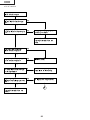
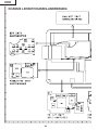
PG-M20X
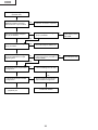
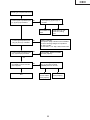
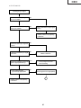
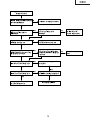
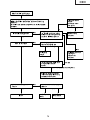
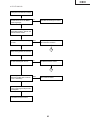
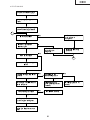
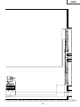
Lamp failure to light up
(formatter unit)
Is any of the SC9001, SC9002,
P9002 and P9003 connectors
disconnected or in poor contact?
Yes
Insert the connectors completely.
No
Is there the specified voltage at
pin (15) of SC9002?
Yes
Is there the 180-Hz pulse signal at
pin (1) of P9002?
No
Is there the specified voltage at
pin (11) of P3002?
No
Check the fan circuit
(near IC2101) on the
KEY PWB.
Yes
Yes
Check the lamp and ballast unit.
No
Is there the 180-Hz pulse signal at
pin (2) of P9003 when no input
signal is given?
Yes
Is the signal at pin (10) of IC9101
at High level?
No
Are there the specified voltages
at pins (23) and (24) of P3003 on
the input PWB?
Yes
No
Go to "Checking of PC I/F unit"
Yes
No
Is the signal at pin (9) of IC9101
at High level?
No
Are the signals at pins (69) and
(70) of SC9001 at High level?
Yes
Yes
Trouble with IC9101 or its
peripheral part.
Trouble with IC9003.
30
No
Check the power unit.
PG-M20S
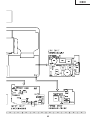
PG-M20X
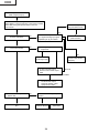
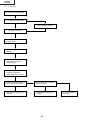
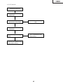
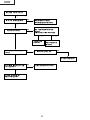
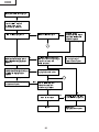
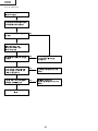
Lamp does not light up.
Yes
Is the cooling fan rotating?
No
Check the power circuit or the fan
circuit on the key/input PWB.
No
Check IC3101, the motor driver
circuit and their periphery.
Check the waveform of SC3101.
Yes
Is the color wheel rotating sound
heard?
Yes
Normal
Replace the color
wheel.
Is the lamp discharging sound
heard?
Yes
Abnormal
Check the
formatter PWB.
Check the socket
No
No
Replace the lamp.
Is DC 340V voltage applied across No
the ballast power?
Check the power circuit.
Yes
Go to "Lamp failure to light up
(formatter unit)".
31
PG-M20S
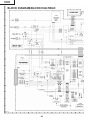
PG-M20X
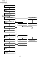
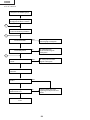
Checking of Sub-microprocessor
and Its Periphery
Does POWER LED flicker in red
(for 2 seconds)?
No
Yes
Is there B+3.3V output at pins (12)
and (13) of CN3701?
Yes
No
Is there 6V output at pins (5) and
(6) of P2003?
No
Go to "Checking of PC I/F Unit", and check
the flexible connector.
Communication error of sub-microprocessor
(KEY) and SH microprocessor (PC I/F unit)
Pins (20) and (21) of P2001.
Check Q2001 thru Q2004
and IC2001.
Yes
Go to "Checking of Power Unit"
Is Bu+6.2V signal outputted?"
No
Go to "Checking of
Power Unit"
No
Check IC2010 and its
periphery.
No
Check IC2010 and its
periphery.
Yes
Is Bu+3.3V signal outputted?
Yes
Is 3.3V signal output at pin
(19) of IC2001?
Yes
Check IC2001 and its
periphery and go to
"Checking of Remote Control
Communication".
32
PG-M20S
PG-M20X
Checking of Low-pass Filter Circuit
Is video signal is inputted to pins
(4), (8) and (12) of IC3851?
No
Check pins (4), (8) and (12) of
SC3001.
Normal
Yes
Check Q3854 and
Q3855.
Is video signal inputted to pins
(24), (21) and (17) of IC3851?
Check the PC I/F unit.
Check DVI (analog)
input.
No
IC3851 is defective.
If the picture quality is abnormal, check whether
or not the following voltages are outputted to
pin (28) of IC3851.
0.3 V for 480i, 1 V for 720p, 1080i, Check IC301.
No
Check Q3851, Q3852 and Q3853
and their periphery.
No
Is the video signal inputted to pins
(8), (17) and (23) of IC8013
(AD9888) of the PC I/F unit?
Yes
Is video signal is inputted to pins
(16), (20) and (24) of IC3001?
Abnormal
Yes
The low-pass filter circuit on the
input PWB is normal. Does the
picture appear?
Yes
End
Yes
Check the SOG
circuit or IC8013
and its periphery.
33
No
Check IC8013
and its periphery.
PG-M20S
PG-M20X
Checking of DTV
(480i Component Input)
Feed the 480i component signal in INPUT 1.
Select INPUT 1 using the set's key or the remote controller.
Select 480i among the special modes on the user
menu screen.
Go to "Checking of
Low-pass Filter Circuit"
Yes
Yes
Is picture outputted?
No
Confirmation of synchronization.
Is Y signal including sync signal
inputted to pin (3) of IC3502?
No
Is the signal type set to the
component?
Check IC8016
(Video decoder).
Yes
Is the color normal?
Yes
No
Yes
No
Check IC3501 and its
periphery.
Set the signal type.
In case of monitor output,
disconnect the monitor output
cable.
Abnormal
Restored to normal condition
Set the monitor output.
Check the monitor output
equipment and cable.
Does the contour of picture
appear clear.
Yes
End
No
Is 480i selected among the special
modes?
Yes
IC8025 is defective.
34
No
Select 480i.
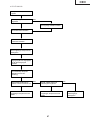
PG-M20S
PG-M20X
Checking of Video Input
Feed the composite video signal to
INPUT 3. Select INPUT 3 using the
set's key or the remote controller.
Does the picture appear?
Yes
Is the picture disturbed?
No
Are pin(5) (horizontal) and
pin(10) (vertical) signals
inputted to IC8363 on the
PC I/F unit?
Yes
No
No
Yes
1
Is the video signal including sync
Yes
signal inputted to pin (3) of SC3001
on the input PWB?
Check IC8363 and
IC8025 (CVIC2) and
their periphery.
Check IC8016 (video decoder)
of PC board and its periphery.
Check Q8002.
No
Is the video signal including sync
signal inputted to pin (7) of IC3501
on the input PWB?
Yes
Check Q3512 and Q3513 on
the input PWB.
No
1
Check IC3501 and its peripheral
circuit.
No
Feed the S-video signal to INPUT 2.
Select INPUT 2 using the set's key
or the remote controller. Does the
picture appear?
Yes
Yes
Is the color normal?
Yes
End
35
No
Is the C signal inputted
to pin (11) of SC3001?
No
Check Q3502 on the
input PWB.
PG-M20S
PG-M20X
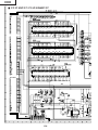
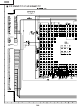
» FORMATTER Unit
Abnormal picture
Blackout
Rainbow-like picture
Others
No
No
Go to "Lamp Does Not
Light Up."
Is signal outputted at
pins (3), (5) and (7) of
SC9001?
No
Is the lamp on?
Go to "Checking of PC I/F nunit"
Yes
Trouble with IC9003,
IC9006 or their periphery
Is any of SC9001, SC9002, P9002
and P9003 connectors
disconnected or in poor contact?
Yes
Insert the connectors
completely.
No
Check the regulator ICs on the
input PWB and KEY PWB.
No
Is an appropriate voltage supplied
to SC9002?
Yes
Reassemble the DMD, optical
mechanism and formatter unit.
Is the symptom improved?
Yes
End
No
Is the voltage at the positive-polarity
pin of C9066 appropriate (+7V)?
No
Trouble with peripheral circuit
of C9066 or trouble with IC9003.
No
Trouble with peripheral circuit
of C9068 or trouble with IC9003.
No
Trouble with peripheral circuit
of C9562 or trouble with IC9003.
Yes
Is the voltage at the positive-polarity
pin of C9068 appropriate (+23 to +26V)?
Yes
Is the voltage at the negative-polarity
pin of C9562 appropriate (-26V)?
Yes
Trouble with the DMD
36
Yes
PG-M20S
PG-M20X
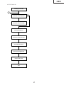
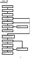
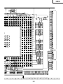
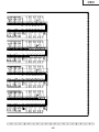
» PC I/F Unit-1/12
Checking of PC PWB
0
Yes
Is the user menu displayed?
No
Check the onscreen display.
Check the RGB input.
Check the component input.
Check the video input.
Check the DVI digital input.
PCカードのチェック
Check the PC card.
End
37
PG-M20S
PG-M20X
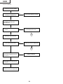
» PC I/F Unit-2/12
Checking of Onscreen Display
Is the user menu displayed
normally by the MENU key?
Yes
The onscreen display is normal.
No
Enter the process menu and select
PATTERN. Then select the
COLOR pattern.
Is the onscreen display color
normal?
No
Adjust the DLP system in the
process adjustment mode.
Yes
0
Make STEP signal selection.
Is the STEP signal normal?
Yes
Rewrite the onscreen display data.
No
0
Is the signal compatible with the
STEP signal outputted at TL106
thru TL111?
No
IC8025 is defective.
Yes
Go to "Checking of GA4 and Its
Periphery".
Rewrite the onscreen display data.
38
PG-M20S
PG-M20X
» PC I/F Unit-3/12
Checking of RGB Input
Feed the sync separation type
analog RGB signal to INPUT 1.
1
Select INPUT 1 using the set's
key or the remote controller.
2
Does the picture appear?
No
Go to "Confirmation of
Video Input".
Yes
Is the picture disturbed?
Yes
Go to "Checking of Sync Signal".
No
3
Do the three colors R, G and B
appear?
No
Go to "Checking of RGB Signal".
Yes
Carry out the AUTOSYNC process.
Is the contour of picture clear?
No
Yes
Is there any disturbance in the
vertical stripe pattern?
Yes
IC8013, 8025 or its periphery is
defective.
No
End
39
PG-M20S
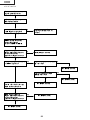
PG-M20X
» PC I/F Unit-4/12
Confirmation of Video Input
Make "Confirmation of Input
Signal Setting".
Is there video signal at the land
of C8070?
No
Is there signal at the terminal C2 of
P8001 (DVI connector)?
Yes
Yes
Somewhere in the signal route is
defective. Check the capacitors and
resistors between the connector
and IC8013.
Go to "Checking of Sync Signal".
IC8025 or IC8013 is defective.
The signal source or connector
is defective.
Confirmation of Input Signal Setting
Is the input menu selected
correctly?
No
Select the input menu correctly.
Yes
2
Are the connectors connected
correctly?
No
Connect the connectors correctly.
Yes
1
End
40
No
PG-M20S
PG-M20X
» PC I/F Unit-5/12
Checking of Sync Signal
Is there the vertical sync signal at
pin (11) of IC8363?
No
Yes
Is there the horizontal sync signal
at pin (5) of IC8363?
No
Make confirmation of input signal
setting.
Yes
IC8330, IC8331 or its periphery
is defective.
Is there the vertical sync signal at
TL8131?
No
Yes
Is there the horizontal sync signal
at TL8130?
No
IC8363 is defective.
Yes
Are both the vertical and horizontal
signals in appropriate timing?
Yes
The sync signal is normal.
End of checking.
No
Is the signal generator
(input source) appropriate?
No
Set the signal source appropriately.
Yes
2
IC8330, IC8331 or its periphery
is defective.
41
PG-M20S
PG-M20X
» PC I/F Unit-6/12
Checking of R, G and B Signals
Is the signal type set to RGB?
No
Yes
Set the signal type to RGB.
Set the process mode.
Select R, G and B individually on
the pattern menu.
Go to "Checking of GA4 and Its
Periphery".
For checking the input signal,
set the signal generator to
gradation signal.
Check TL8169, TL8170 and
TL8180 by oscilloscope.
(MSB bit after A/D conversion)
Are there the specified signals at
TL8169, TL8170 and TL8180?
No
Does the signal come to C8062,
C8070 and C8078?
Yes
IC8025 and its periphery are
defective.
No
Yes
IC8013 and its periphery are
defective.
42
Go to "Confirmation of
Video Input".
PG-M20S
PG-M20X
» PC I/F Unit-7/12
Checking of GA4 and Its Periphery
Select R, G and B individually on
the pattern menu in process mode.
Is picture outputted appropriately
in R, G and B?
Yes
Checking of GA4 and its periphery
ends.
No
Check pins (72), (52) and (32) of
SC8001 by oscilloscope.
These signals are MSB of B/G/R.
Do the signals selected on the
pattern menu match with those
checked by oscilloscope?
Yes
The DLP PWB is defective.
No
Does the clock signal come to pin
(78) of SC8001?
No
Is there the clock (32.5 MHz)
signal at TL8114?
Yes
Yes
No
IC8029 is defective.
Is there the clock (32.5 MHz)
signal at TL8110?
No
Yes
X8005 is defective.
Check TL8106, TL8107, TL8108,
TL8109, TL81010 and TL81011
by oscilloscope.
Do the signals selected on the
pattern menu match with those
checked by oscilloscope?
IC8025 is defective.
No
IC8025 is defective.
Yes
IC8029 is defective.
43
PG-M20S
PG-M20X
» PC I/F Unit-8/12
Checking of Component Input
(except 480I)
Feed the component signal to
INPUT 1.
Select INPUT 1 using the set's
key or the remote controller.
Is the picture appear?
No
Go to "Checking of SOG Circuit".
Yes
4
Is the color normal?
No
Is the signal type set at component?
No
Yes
Set the signal type to component.
Carry out the process adjustment.
4
Is the contour of picture clear?
No
IC8013 or IC8025 is defective.
Yes
The component is normal. End.
44
PG-M20S
PG-M20X
» PC I/F Unit-9/12
Checking of SOG Circuit
Check pin (2) of IC8365 by
oscilloscope.
Is the composite sync signal
reproduced in correct timing?
Yes
The SOG circuit is normal.
End.
No
Go to "Confirmation of Input
Signal Setting".
No
Check the land of C8070 by
oscilloscope.
Is there the Y signal including sync
signal?
Yes
The SOG sync separation circuit
(input PWB) is defective.
45
PG-M20S
PG-M20X
» PC I/F Unit-10/12
Checking of Video Input
Feed the composite video signal to
INPUT 3.
Select INPUT 3 using the set's key
or the remote controller.
5
Is the picture appear?
No
Go to "Checking of Video
Sync Signal".
Yes
Is there any disturbance in the
picture?
Yes
No
Go to "Checking of Video
Sync Signal".
Carry out the process
adjustment.
No
Is the color normal?
5
Yes
The video input is normal. End.
Is the video signal inputted to
C8141?
No
Is there the specified signal
at R8114?
Yes
Yes
Check the clock signal of IC8015
by FL8114.
Is the clock signal normal?
No
Q8002 and its periphery are
defective.
No
IC8015 is defective.
Yes
Go to "Checking of Video Sync
Signal".
IC8025 and its periphery are
defective.
46
Input PWB is defective.
PG-M20S
PG-M20X
» PC I/F Unit-11/12
Checking of Video Sync Signal
Check pin (10) of IC8363 by
oscilloscope.
(Checking of vertical sync signal)
Is the vertical sync signal normal?
No
Yes
Check pin (6) of IC8363 by
oscilloscope.
(Checking of horizontal sync signal)
Is the horizontal sync signal
normal?
No
Go to "Confirmation of Input Signal
Setting".
No
IC8015 and its periphery are
defective.
No
IC8015 and its periphery are
defective.
Yes
Are the horizontal sync signal and
vertical sync signal outputted at
TL8130 and TL8131?
Yes
Is there the specified clock
(13.5 MHz) signal at FL8114?
Yes
End
47
PG-M20S
PG-M20X
» PC I/F Unit-12/12
Checking of DVI Digital Input
Feed the DVI digital signal to
INPUT 1.
Select INPUT 1 for input.
Is the picture appear?
No
Yes
Is there any disturbance in the
picture?
No
Yes
Is the color normal?
No
IC8298 and its periphery are
defective.
Yes
The DVI digital input is normal.
Check pin (13) of IC8363 for vertical
sync signal, and check pin (3) of
IC8363 for horizontal sync signal.
Are the sync signals normal?
No
Yes
Check R8685 for clock signal.
Is the clock signal normal?
No
IC8298 and its periphery are
defective.
Yes
IC8025 and its periphery are
defective.
48
PG-M20S
PG-M20X
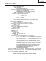
Technische Daten
Produkttyp Digitaler Multimedia-Projektor
Modell PG-M20X/PG-M20S
Videosystem NTSC 3.58/NTSC 4.43/PAL/PAL-M/PAL-N/PAL 60/SECAM/
DTV480I/DTV480P/DTV720P/DTV1080I
Wiedergabeverfahren Single Chip Digital Micromirror Device™ (DMD™) von Texas Instruments
DMD-Panel Panel-Größe: 0,7" (17,8 mm), 1 Chip XGA DMD(PG-M20X)/
0.55"(140.0mm), 1 chip SVGA DMD(PG-M20S)
Anzahl der Bildpunkte: 786.432 Bildpunkte (1.024 [H] × 768 [V])(PG-M20X)
480.000 Bildpunkte (800 [H] × 600 [V])(PG-M20S)
Objektiv 1–1.2 × Zoom-Objektiv, F1,75–2,04, f = 28,0–33,5 mm
Projektionslampe Hochleistungslampe (HID-Lampe), DC 210 W
Komponenten-Eingangssignale 29-pol. Anschluss
(INPUT 1) DVI-Eingangssignal: Digital 250–1.000 mV 50 Ω
Analog 0,7 Vs-s 75 Ω
Y: 1,0 Vs-s, negatives Sync., 75 Ω terminiert
PB: 0,7 Vs-s, 75 Ω terminiert
PR: 0,7 Vs-s, 75 Ω terminiert
Horizontale Auflösung 700 Fernsehzeilen (DTV720P)(PG-M20X)/500 Fernsehzeilen (S-Video[NTSC3.58])(PG-M20S)
Computer-RGB-Eingangssignal 29-pol. Anshluss
(INPUT 1) RGB getrennt/Sync auf Grün-Typ analoger Eingang: 0-0,7 Vs-s, positiv, 75 Ω terminiert
HORIZONTALES SYNC.-SIGNAL: TTL-Pegel (positiv/negativ)
VERTIKALES SYNC.-SIGNAL: Wie oben
S-Videoeingangssignal 4-pol. Mini DIN-Anschluss
(INPUT 2) Y (Luminanzsignal): 1,0 Vs-s, negatives Sync., 75 Ω terminiert
C (Chrominanzsignal): Stoß 0,286 Vs-s, 75 Ω terminiert
Videoeingangssignal RCA-Anschluss: VIDEO, gemischtes Video, 1,0 Vs-s, negatives Sync.,
(INPUT 3) 75 Ω terminiert
Pixeltakt 12-230 MHz(PG-M20X)/12-120MHz(PG-M20S)
Vertikale Frequenz 43-100 Hz
Horizontale Frequenz 15-126 kHz(PG-M20X)/15-102kHz(PG-M20S)
Audioeingangssignal ø 3,5 mm Minibuchse: AUDIO, 0,5 Vrms, mehr als 47 kΩ (Stereo)
Audioausgang 2,0 W (Mono)
Lautsprechersystem 4 cm × 3 cm
Nennspannung 100-240 V Wechselstromspannung
Eingangsspannung 3,2 A
Nennfrequenz 50/60 Hz
Leistungsaufnahme 290 W
Stromverlust <1.090 kWh
Betriebstemperatur 41°F bis 95°F (+5°C bis +35°C)
Lagertemperatur –4°F bis 140°F (–20°C bis +60°C)
Gehäuse Plastik
I/R-Trägerfrequenz 38 kHz
Abmessungen (ca.) 8 5⁄8" × 3" × 11 15⁄16" (219 (B) × 76 (H) × 303 (T) mm) (nur Hauptgerät)
8 3⁄4" × 3 1⁄4" × 12 1⁄2" (223 (B) × 83 (H) × 318 (T) mm) (einschließlich Drehfüße und Projektionsteile)
Gewicht (ca.) 5,8 lbs. (2,6 kg)
Mitgeliefertes Zubehör Fernbedienung, zwei R-03-Batterien, Netzkabel für USA, Kanada usw. (6', 1,8 m), Netzkabel für
Europa, ausgenommen Großbritannien (6', 1,8 m), Netzkabel für Großbritannien, Hongkong und
Singapur (6', 1,8 m), Netzkabel für Australien, Neuseeland und Ozeanien (6', 1,8 m), DVI an 15-Pin
D-Sub-Kabel (6', 1,8 m), USB-Kabel (6', 1,8 m), Tragetasche, Objektivkappe (befestigt), Riemen für
Objektivkappe, Anschlussabdeckung (befestigt), CD-ROM, Bedienungsanleitung, Kurzanleitung
Ersatzteile Lampeneinheit (Lampen-/Gehäusemodul) (BQC-PGM20X//1) Fernbedienung (RRMCGA013WJSA),
zwei R-03-Batterien (“AAA”, UM/SUM-4, HP-16 oder ähnlich), Netzkabel für USA, Kanada usw.
(QACCDA007WJPZ), Netzkabel für Europa, ausgenommen Großbritannien (QACCV4002CEZZ),
Netzkabel für Großbritannien, Hongkong und Singapur (QACCB5024CENA[PG-M20X]/QACCBA012
WJPZ[PG-M20S]), Netzkabel für Australien, Neuseeland und Ozeanien (QACCL3022CEZZ), DVI an
15-Pin D-Sub-Kabel (QCNWGA010WJZZ), USB-Kabel (QCNWG0001WJPZ), Tragetasche
(GCASN0005CESA), Objektivkappe (CCAPHA001WJ01), Riemen für Objektivkappe
(UBNDT0013CEZZ), Anschlussabdeckung (GCOVD0103CESA), CD-ROM (UDSKA0058CEN1
[PG-M20X]UDSKAA009WJZZ{PG-M20S}),Bedienungsanleitung (TINS-7609CEZZ[PG-M20X]/
TiNS-A209WJZZ[PG-M20S]),Kurzanleitung
Dieser Projektor von SHARP ist mit einem DMD-Panel
ausgestattet. Diese neuartigen Panel enthalten 786.432
(PG-M20X)/480.000(PG-M20S) Bildpunkte.Bei allen technologisch
fortschrittlichen, elektronischen Geräten, z. B. Großbild-Fernsehern,Videosystemen bzw. Videokameras, sind bestimmte Toleranzgrenzen für die Funktionen gegeben.
Dieses Gerät hat einige inaktive, innerhalb akzeptierter
Toleranzgrenzen liegende Bildpunkte, die als leuchtende oder als
nicht aktive Punkte auf der Bildwand wiedergegeben werden. Dies
hat keinen Einfluss auf die Bildqualität oder die Lebensdauer des
Gerätes.
Änderungen der technischen Daten ohne vorherige Ankündigung vorbehalten.
49
PG-M20S
PG-M20X
HINWEIS FÜR DAS WARTUNGSPERSONAL
12345678901234567890123456789012123456789012345
12345678901234567890123456789012123456789012345
Ë Auswechseln der Lampe
ACHTUNG: UV-STRAHLUNG
12345678901234567890123456789012123456789012345
12345678901234567890123456789012123456789012345
12345678901234567890123456789012123456789012345
Hinweis:
Da die Lampe während des Betriebs sehr heiß wird,
sollte die Lampe erst ausgewechselt werden, nachdem
das Gerät mindestens eine Stunde ausgeschaltet war,
damit die Lampe ausreichend abkühlen kann.
Beim Installieren der neuen Lampe muß darauf
geachtet werden, die Lampe selbst (Glaskolben)
nicht zu berühren. Vielmehr muß die Lampe am
Reflektor 2 gehalten werden.
[Es darf nur ein Original-Ersatzteil verwendet
werden.]
Die Lichtquelle im Projektor, eine Metall-HalogenLampe, gibt eine geringe UV-Strahlung ab.
DIREKTE BESTRAHLUNG AUF AUGEN
UND HAUT MUSS VERMIEDEN WERDEN.
Zur Gewährleistung der Sicherheit muß folgendes
beachtet werden:
1. Bei Arbeiten am Projektor bei eingeschalteter
Lampe und abgenommenem oberen Gehäuse
muß unbedingt eine Sonnenbrille getragen
werden.
1 Lampe
2 Reflektor
GEFAHR! — Niemals die Spannungsversorgung
einschalten, ohne daß eine Lampe vorhanden ist,
um elektrische Schläge und Schäden am Gerät zu
vermeiden, da der Stabilisator anfangs hohe
Spannungen erzeugt.
2. Die Lampe darf nicht außerhalb des
Lampengehäuses eingeschaltet werden.
Da eine geringe UV-Strahlung aus einer Öffnung
zwischen der Schachtabdeckung und dem
Lampengehäuse austritt, sollte der Objektivdeckel
bei Wartungsarbeiten auf die Öffnung gesetzt
werden, um die Bestrahlung von Augen und Haut
zu vermeiden (Abb. 1).
3. Betrieb für länger als 2 Stunden bei
abgenommenem Gehäuse ist nicht zulässig.
Hinweis: Besorgen Sie sich einen Objektivdeckel,
bevor Sie Arbeiten an einem Modelle PGM20X/PG-M20S durchführen, das keinen
Objektivdeckel aufweist.
Zur Beachtung bei UV-Strahlung
und Mitteldruck-Lampen
1. Vor dem Auswechseln der Lampe muß der
Netzstecker gezogen werden.
2. Vor Durchführung von Wartungsarbeiten muß das
Gerät eine Stunde abkühlen.
3. Nur mit dem gleichen Lampentyp ersetzen Typ
BQC-PGM20X//1; Nennleistung 85 V/210 W.
4. Die Lampe gibt eine geringe UV-Strahlung ab,
daher muß direkter Augenkontakt vermieden
werden.
5. Die Mitteldruck-Lampe weist ein Explosionsrisiko
auf. Daher müssen die nachstehenden
Installationsanweisungen beachtet werden, und die
Lampe muß vorsichtig behandelt werden.
Abbildung 1.
50
PG-M20S
PG-M20X
Vorsichtsmaßregeln für bleifreien Lötzinn
1 Verwendung von bleifreiem Lötzinn
Die "Eingangs-und Schlüssel-Platine" dieses Modells verwendet bleifreien Lötzinn. Das LF-Symbol zeigt bleifreien
Lötzinn an und ist an den Platinen und Wartungsanleitungen angebracht. Der Buchstabe nach LF zeigt den Typ des
bleifreien Lötzinns an.
Beispiel:
LFa
Zeigt bleifreien Lötzinn aus Zinn, Silber und Kupfer an.
2 Bei Reparatur der mit bleifreiem Lötzinn gelöteten Platine immer bleifreien Lötzinn verwenden. Reparatur mit
herkömmlichem Lötzinn kann zu Schäden oder Unfällen aufgrund von Rissen führen.
Da der Schmelzpunkt bleifreien Lvtzinns (Sn-Ag-Cu) um 40°C höher als der von Bleidraht-Lötzinn ist, empfehlen wir
die Verwendung einer speziellen Lötspitze. Wenn Fragen über den Beschaffung leitfreien Lötzinns oder spezieller
Lötspitzen bestehen, wenden Sie sich an unsere Kundendienstvertretung in Ihrem Gebiet.
3 Löten
Da der Schmelzpunkt bleifreien Lötzinns (Sn-Ag-Cu) etwa 220°C beträgt, was um 40°C höher als der von bleihaltigem
Lötzinn ist, und außerdem schlechte Löt-Benetzbarkeit aufweist, kann es erforderlich werden, die Lötspitze längere
Zeit in Kontakt mit der Platine zu halten. Da die Lötlauge abfliessen kann oder der maximale Hitzewiderstand von
Teilen überschritten werden kann, die Lötspitze sofort von der Platine nehmen, sobald eine gute Lötung erzielt ist.
Bleifreier Lötzinn enth_lt mehr Zinn, und das Ende der Lötspitze kann leicht angegriffen werden. Immer sicherstellen,
dass der Lötkolben nur bei Bedarf eingeschaltet wird.
Wenn ein anderer Typ von Lötzinn an der Lötspitze haften bleibt, verschmilzt er mit dem bleifreien Lötzinn. Die
Lötspitze nach jeder Verwendung reinigen.
Wenn die Lötspitze bei der Verwendung geschwärzt wird, die Spitze mit Stahlwolle oder feinem Sandpapier
abschmirgeln.
Immer beim Austausch von Teilen vorsichtig sein, und die Polaritätsanzeige auf der Platinenbeschriftung beachten.
Bleifreier Lötzinn zur Wartung
Teile-Nr.
ZHNDAi123250E
ZHNDAi126500E
ZHNDAi12801KE
★
J
J
J
Beschreibung
φ0.3mm
250g(1roll)
φ0.6mm
500g(1roll)
φ1.0mm
1 Rolle
51
Code
BL
BK
BM
PG-M20S
PG-M20X
Bedienelemente
Projektor (Vorder- und Draufsicht)
LAMP-Anzeige
(Lampenaustausch)
TEMP.-Anzeige
(Temperaturwarn)
Leuchtet normalerweise grün. Die
Lampe austauschen, wenn die
Anzeige rot leuchtet.
Leuchtet normalerweise
grün. Wenn die interne
Temperatur ansteigt, leuchtet
diese Anzeige rot.
POWER-Anzeige (Netz)
Leuchtet rot, wenn sich der
Projektor im Bereitschaftsbetrieb
befindet. Wenn die Stromversorgung eingeschaltet ist,
leuchtet diese Anzeige grün.
INPUT-Taste
Für das Umschalten
zwischen Eingangsmodus 1,
2 und 3.
MENU-Taste
POWER-Taste
Schaltet die Stromversorgung
ein oder aus.
Für die Anzeige des Justierungs- und Einstellungsbildschirms.
LENS-Taste
VOL-Tasten
Für das Einstellen der
Trapezverzerrungs- oder Digitalen
Verschiebungs-Einstellung.
Einstelltasten (
Für das Einstellen des
Lautsprecher-Tonpegels.
UNDO-Taste
)
Für das Rückgängigmachen
eines Bedienschrittes oder
für die Rückkehr zu den
Grundeinstellungen.
Für die Wahl der Menüpunkte.
ENTER-Taste
Für die Einstellung der gewählten
oder eingestellten Menüpunkte.
AUTO SYNC-Taste
Für das automatische
Einstellen von Bildern,
wenn ein Computer
angeschlossen ist.
AV MUTE-Taste
Für das vorübergehende
Ausschalten des Tons und des
Bildes.
Fokusring
Zoom-Knopf
Anschlussabdeckung
Lautsprecher
Fernbedienungssensor
Fußentriegelungen/
Einstellfuß
Für das Einstellen der Projektorhöhe.
Befestigen der
Anschlussabdeckung
Die Anschlussabdeckung an der
Projektorseite befestigen und
eindrücken, wie in der Abbildung
gezeigt.
52
PG-M20S
PG-M20X
Projektor (Seitenansicht)
USB-Anschluss
INPUT 1-Anschluss
Schnittstelle für DVI Digital-,
Computer RGB- und COMPONENT-Signale.
Für den Anschluss eines
Computers mittels USBKabel.
INPUT 2-Anschluss
INPUT AUDIOAnschluss
Anschluss für ein Videogerät mit
einem S-VIDEO-Anschluss.
Gemeinsam genutzter
Audioanschluss für INPUT
1, INPUT 2 und INPUT 3.
Netzanschluss
INPUT 3-Anschluss
Für den Anschluss eines
Videogerätes.
Luftaustrittöffnung
Kensington-Sicherheitsstandardanschluss
Verwendung der Kensington-Sperre
• Dieser Projektor ist mit einem Kensington-Sicherheitsstandardanschluss für die Verwendung des Kensington MicroSaverSicherheitssystem ausgestattet. Lesen Sie hinsichtlich der Verwendung die Informationen, die dem System beiliegen, um
den Projektor zu sichern.
Befestigen der Objektivkappe
Nach dem Befestigen des Riemens an der
Objektivkappe das andere Ende des Riemens
durch das Loch unter dem Projektor neben
dem Objektiv hindurch führen, wie in der
Abbildung gezeigt.
Ansicht von unten
53
PG-M20S
PG-M20X
Fernbedienung
Fernbedienungssignal-Sender
FORWARD/BACK-Taste
POWER-Taste
Schaltet nach vorne oder hinten,
wenn ein Computer mittels eines
USB-Kabels angeschlossen ist. Wie
die [Page Up]- und [Page Down]Tasten auf der Computer-Tastatur.
Schaltet die Stromversorgung ein oder
aus.
ENLARGE-Tasten (Vergrößern/
Verkleinern)
Für das Vergrößern oder Verkleinern
eines Bildteils.
AV MUTE-Taste
Für das vorübergehende
Ausschalten des Tons und des
Bildes.
FREEZE-Taste
Für das Einfrieren von Bildern.
INPUT 3-Taste
VOLUME-Tasten
Für das Umschalten des
Eingangsmodus zu EINGANG 3.
Für das Einstellen des
Lautsprecher-Tonpegels.
RESIZE-Taste
Für das Umschalten der Bildwandgröße
(NORMAL, UMRANDLING usw).
INPUT 2-Taste
Für das Umschalten des
Eingangsmodus zu EINGANG 2.
GAMMA-Taste
INPUT 1-Taste
AUTO SYNC-Taste
Für das Korrigieren der Helligkeit eines
Bildes, wenn das angezeigte Bild
aufgrund der Raumhelligkeit schwierig
zu sehen ist. Sie können aus vier
verfügbaren Gamma-Modi auswählen.
Für das automatische Einstellen
von Bildern, wenn ein Computer
angeschlossen ist.
MENU-Taste
LENS-Taste
Für die Anzeige des Justierungs- und
Einstellungsbildschirms.
Für das Umschalten des
Eingangsmodus zu EINGANG 1.
Für das Einstellen der
Trapezverzerrungs- oder Digitalen
Verschiebungs-Einstellung.
Einstelltasten (
)
Für die Wahl der Menüpunkte.
ENTER-Taste
Für die Einstellung der gewählten
oder eingestellten Menüpunkte.
UNDO-Taste
Für das Rückgängigmachen eines
Bedienschrittes oder für die Rückkehr
zu den Grundeinstellungen.
54
PG-M20S
PG-M20X
Pin-Belegung
DVI Digital-/Analog-EINGANG 1-Port: 29 Pin-Anschluss
• DVI-Digital-EINGANG
9
•••••••••
1 2
••••
Pin-Nr.
1
2
3
4
5
6
7
8
9
10
11
12
13
14
15
~ • • • • • • • • • 16
~ •••• 7 8
C1
C2
C4
C5
C3
17
24
18
••••
~ • • • • 23
• DVI-Analog-RGB-Eingang
Pin-Nr.
1
2
3
4
5
6
7
8
9
10
11
12
13
14
15
Signal
Nicht angeschlossen
Nicht angeschlossen
Nicht angeschlossen
Nicht angeschlossen
Nicht angeschlossen
DDC-Taktgeber
DDC-Daten
Vertikales Sync.
Nicht angeschlossen
Nicht angeschlossen
Nicht angeschlossen
Nicht angeschlossen
Nicht angeschlossen
+5V-Stromversorgung
Masse
Signal
Pin-Nr.
T.M.D.S-Daten 2–
16
T.M.D.S-Daten 2+
17
T.M.D.S-Daten 2 Abschirmung 18
Nicht angeschlossen
19
Nicht angeschlossen
20
DDC-Taktgeber
21
DDC-Daten
22
Nicht angeschlossen
23
T.M.D.S-Daten 1–
24
T.M.D.S-Daten 1+
C1
T.M.D.S-Daten 1 Abschirmung C2
Nicht angeschlossen
C3
Nicht angeschlossen
C4
+5V-Stromversorgung
C5
Masse
• DVI-Analog-Komponenten-Eingang
Pin-Nr.
16
17
18
19
20
21
22
23
24
C1
C2
C3
C4
C5
Signal
Hot Plug festgestellt
Nicht angeschlossen
Nicht angeschlossen
Nicht angeschlossen
Nicht angeschlossen
Nicht angeschlossen
Nicht angeschlossen
Nicht angeschlossen
Nicht angeschlossen
Analogeingang Rot
Analogeingang Grün
Analogeingang Blau
Horizontales Sync.
Masse
Pin-Nr.
1
2
3
4
5
6
7
8
9
10
11
12
13
14
15
Signal
Nicht angeschlossen
Nicht angeschlossen
Nicht angeschlossen
Nicht angeschlossen
Nicht angeschlossen
Nicht angeschlossen
Nicht angeschlossen
Nicht angeschlossen
Nicht angeschlossen
Nicht angeschlossen
Nicht angeschlossen
Nicht angeschlossen
Nicht angeschlossen
Nicht angeschlossen
Masse
Pin-Nr.
16
17
18
19
20
21
22
23
24
C1
C2
C3
C4
C5
4-Pin-USB-Anschluss
• USB-Anschluss: 4 Pin B-Typ USB-Anschluss
2
1
3
4
Signal
Hot Plug festgestellt
T.M.D.S-Daten 0–
T.M.D.S-Daten 0+
T.M.D.S-Daten 0 Abschirmung
Nicht angeschlossen
Nicht angeschlossen
T.M.D.S-Taktgeber Abschirmung
T.M.D.S-Taktgeber+
T.M.D.S-Taktgeber–
Nicht angeschlossen
Nicht angeschlossen
Nicht angeschlossen
Nicht angeschlossen
Masse
Pin Nr.
1
2
3
4
Signal
VCC
USB–
USB+
SG
55
Bezeichnung
USB-Strom
USB-Daten–
USB-Daten+
Signal-Masse
Signal
Nicht angeschlossen
Nicht angeschlossen
Nicht angeschlossen
Nicht angeschlossen
Nicht angeschlossen
Nicht angeschlossen
Nicht angeschlossen
Nicht angeschlossen
Nicht angeschlossen
Analogeingang Pr/Cr
Analogeingang Y
Analogeingang Pb/Cb
Nicht angeschlossen
Masse
PG-M20S
PG-M20X
Abmessungen
Ansicht von
hinten
Einheiten: Zoll (mm)
Ansicht von
oben
Ansicht von
der Seite
12 9/16
(318,3)
Ansicht von
der Seite
11 15/16
(302,5)
8 3/4 (223)
8 5/8 (219)
5 1/16 (128)
Ansicht von
vorne
3
3 1/4
1 1/2
(38,7) (76,1) (82,9)
3/8
1
(34,2)
4 9/16 (115,5)
7 11/16 (195)
3 1/4 (82,5)
2 3/16
(55,5)
3 1/8
(80)
Ansicht von
unten
2 3/8
(60)
5/16
(7,5)
4 1/8
(104)
10 5/16
(261,5)
56
PG-M20S
PG-M20X
ENTFERNEN DER HAUPTTEILE
1. Ausbau der Oberabdeckung
1-1.
1-2.
1-3.
1-4.
1-5.
1-6.
Die Klemmenblock-Abdeckung entfernen.
Die fünf Sperrschrauben von der Oberabdeckung entfernen.
Die rechte Seite des Unterteils drücken, um den Haken zu lösen.
Die linke Seite des Unterteils drücken, um den Haken zu lösen.
Die vordere Seite des Unterteils drücken, um den Haken zu lösen. Die Oberplatte vom Unterteil lösen.
Leicht die Vorderseite der Oberplatte anheben, und den Lautsprecher-Steckverbinder abtrennen.
2. Ausbau der PC-Schnittstellen-Platine und des Kühlgeblöses
2-1. Den Steckverbinder abtrennen.
2-2. Die drei Sperrschrauben von der PC-Schnittstellen-Platine entfernen, und dann die beiden SechskantHalteschrauben entfernen.
2-3. Den Steckverbinder abtrennen, und das Kühlgeblöse herausnehmen.
Oberplatte
1-2
1-2
1-6
1-4
1-3
1-2
2-2
1-1
2-1
1-5
1-2
PC-Schnittstellen-Platine
1-2
Klemmenblock-Abdeckung
2-3
2-3
Khlgebse
2-2
57
PG-M20S
PG-M20X
3. Ausbau der Betriebs-Platine
3-1. Die zwei Sperrschrauben von der Betriebs-Platine entfernen, und dann die Platine leicht anheben.
3-2. Die Steckverbinder abtrennen.
4. Ausbau des Optikmechanismus
4-1.
4-2.
4-3.
4-4.
Die beiden Sperrschrauben von der Lampenfassung entfernen.
Die beiden Lampenfassungs-Leitungsbefestigungen anheben.
Die Steckverbinder abtrennen.
Die sechs Sperrschrauben vom Optikmechanismus entfernen.
3-2
3-1
3-1
Betriebs-Platinen-Einheit
4-1
4-2
4-4
Optikmechanismus
4-3
58
PG-M20S
PG-M20X
5. Ausbau der anderen Platinen
5-1.
5-2.
5-3.
5-4.
5-5.
5-6.
Die Steckverbinder abtrennen.
Die vier Sperrschrauben von der Betriebsstrom-Platine entfernen.
Die Sperrschraube von der Vorschaltdrossel-Platineneinheit entfernen.
Die drei Sechskant-Halteschrauben von der Eingangsplatine entfernen.
Die Sperrschraube von der Klemmenblock-Abdeckung entfernen.
Die drei Sperrschrauben von der PFC-Platine entfernen.
5-4
Eingangsplatinen-Einheit
5-5
5-2
5-1
PFC-Platineneinheit
5-3
Vorschaltdrossel-Platineneinheit
5-1
5-6
Betriebsstrom-Platineneinheit
5-1
Unterteil
59
PG-M20S
PG-M20X
6. Ausbau der Formatierer-Platine
6-1. Die Steckverbinder abtrennen.
6-2. Die beiden Sperrschrauben von der Wärmesenke entfernen.
6-3. Die vier Sperrschrauben von der Rückhalteplatten-Bügel entfernen, und die Formatierer-Platine abnehmen.
Hinweis: Die DMD(Digital-Mikrospiegel-Vorrichtung)-Einheit wird leicht durch statische Elektrizität beeinflusst.
Beim Umgang mit diesem Gerät immer ein statikableitendes Armband tragen oder andere Maßnahmen gegen
Statik treffen.
Formattierer-Platineneinheit
6-1
Rückhalteplatten-Baugruppe
6-3
DMD(Digital-MikrospiegelVorrichtung)-Einheit
Wärmesenke
Vorsichtsmaßregeln zur Auswechslung des DMD
(Digital-Mikrospiegel-Vorrichtung) -Chips
Hinweis: Sicherstellen, daß sich keine Staube und
Fingerabdrücke auf dem Deckglas des
DMD-Chips und der Prismen-Oberfläche
des Optikapparats zurücklassen.
1. Beim Festziehen der 4 Schrauben der
Rückhalteplatten-Baugruppe die
Rückhalteplatte auf die Formatier-Platine
niederdrücken und die Schrauben diagonal
festziehen.
2. Falls ein Schatten auf dem Projektionsschirm
erscheint, wie in der Abbidlung 1, die beide
Schrauben von der Spiegeleinstellplatte lockern
und diese Platte bewegen, um das Leuchtfeld
des DMD-Chips einzustellen.
Abbildung 1
6-2
Spiegeleinstellplatte
Formattierer-Platineneinheit
6-1
Rckhalteplatten-Baugruppe
Prismen-Oberflcha
6-3
DMD(Digital-MikrospiegelVorrichtung)-Chip
+ Au§enrahmen
+ Druckfeder
Wrmesenke
Schatten
60
6-2
PG-M20S
PG-M20X
* Vorsichtsmaßregeln zur Einrichtung der DMD(Digital-Mikrospiegel-Vorrichtung)-Einheit
Vor dem Anschließen der Formatierer-Platine an den Optikapparat die folgenden Schritte ausführen. Die SpannngsrangMarkierung am DMD selber prüfen. Entsprechend dieser Markierung die DIP-Schalter an der Formatier-Platine einstellen.
Danach diese Platine an den Optikapparat anschließen. Falsche Einstellungen beeinträchtigen die Systemleistung.
Spannungsstand-Markierung
Diese Probe ist "C".
Spannungsrangsystem mit den DIP-Schaltern an der Formatier-Platine
B
C
D
E
* Anschluss der FPC-Verlängerungskabel (QCNW-A298WJZZ)
Die Kabel an die Formatierer-Platine (TO FMT) und die PC-Schnittstellenplatine (TO PC) entsprechend den
Schablonendruck-Markierungen anschließen. Siehe Skizze unten. (Die FPC ist bereits an TO PC angeschlossen.)
TO FMT
TO PC
61
PG-M20S
PG-M20X
Kurzbeschreibung des Optikapparats
<Layout>
Relaislinsen
Stablinse
Reflektor
Projektionsobjektiv
Lampe
UV/IR-Filter
Prisma
DMD-Chip
Gegenstand
Lampe
UV/IR-Filter
Farbrad
Stablinse
Relaislinsen
Reflektor
Prism
DMD-Chip
Projektionsobjektiv
Farbrad
Funktion
Lichtquelle. Gleichstrombetr iebene Hochdr uckQuecksilberdampflampe.
Zur Absorption von Ultraviolett- und Infrarotstrahlen.
Dient zum Durchlassen der Lichtquelle durch den Farbfilter
und Aufspalten in die Farben R, G und B.
Dient zur Erzeugung uniformer Lichtstrahlen.
Dienen zum Sammeln des Lichts von der Stablinse in den
DMD-Chip.
Dient zum Reflektieren des Lichts von der Relaislinse gegen
den DMD-Chip.
Dient zum Einführen des Lichts vom Reflektor über die
Effektivoberfläche des DMD-Chips. Wenn der Mikrospiegel
gekippt wird (EIN) wie vorgeschrieben, wird das reflektierte
Licht zur Projektionslinse geführt.
Dient zum Einschalten und Ausschalten des Mikrospiegels
als Reaktion auf das Verhältnis der Farbkomponenten bei
jedem Punkt und deshalb zur entsprechenden Reflektion
des einfallenden Lichts.
Dient zum Vergrößern des Lichts vom DMD-Chip und zur
Projektion des Lichts auf den Schirm.
62
PG-M20S
PG-M20X
RÜCKSTELLUNG DES LAMPEN-TIMERS
Den Lampen-Timer nach dem Lampenaustausch
zurückzustellen.
1
Das Netzkabel anschließen.
• Das
Netzkabel am Netzanschluss des
Projektors anschlie§en.
2
Den Lampen-Timer zurückstellen.
• Whrend
,
und
Netzanschluss
auf dem
P r o j e k t o r g l e i c h ze i t i g g e d r ck t w i r d ,
POWER-Taste
auf dem Projektor drcken.
• ÒLAMPE 0000HÓ erscheint und zeigt damit
Einstelltasten
(", |)
an, dass der Lampen-Timer zurckgestellt
ist.
Info
• Stellen
Sie sicher, dass Sie den Lampen-
Timer nur nach dem Austausch der Lampe
zurcksetzen. Wenn Sie den Lampen-Timer
zurcksetzen und dieselbe Lampe weiterhin
verwenden, knnte die Lampe beschdigt
ENTER-Taste
werden oder explodieren.
63
PG-M20S
PG-M20X
WARTUNGSANZEIGEN
■ Die Warnleuchten auf dem Projektor weisen auf Fehlfunktionen im Projektor hin.
■ Falls ein Problem auftritt, leuchtet entweder die Temperaturwarn-Anzeige oder die Lampenaustausch-Anzeige
rot auf und die Stromversorgung wird ausgeschaltet. Nach dem Ausschalten des Gerätes den unten aufgeführten
Schritten folgen.
TemperaturwarnNetz-
Anzeige
Anzeige
Über die
LampenaustauschAnzeige
■Wenn
die
Lampe
Lampenaustausch
1.900
Betriebs-
Anzeige
stunden berschreiÓ auf der Bildwand
tet, blinkt Ò
gelb auf. Wenn 2.000 Betriebsstunden
angezeigt, und die Lampe sowie der
Wenn der Projektor wegen Problemen bei der
Aufstellung
oder
wegen
Blockierens
Luftffnungen zu warm wird, blinkt Ò
Projektor
der
Ó in der
die Lampenaustausch-Anzeige rot
■Nachdem
Lampe aus und die Temperaturwarn-Anzeige
blinkt; der Khlventilator dreht sich fr weitere
einzuschalten,
der
Ó angezeigt wird, unbedingt die folgenden
warn-
Symptom
Aus
Anzeige
Rot ein/
im Inneren des
Strom aus
Gertes ist zu
hoch.
blockiert.
• Khlventilator
beschdigt
• Interne
Schaltkreise
beschdigt
• Luftfilter verstopft
Grn ein
Rot blinkt
Grn
Lampenaus-
blinkt,
tausch-
wenn die
Anzeige
Lampe
aktiviert ist.
Die Lampe muss
Projektor
Problem
• Belftungsffnungen
Die Temperatur
dass
die
nicht
mehr
eingeschaltet werden.
Ma§nahmen durchfhren.
Temperatur-
ohne
Lampe ausgetauscht wurde, kann
S t r o m v e r s o r g u n g a u s g e s c h a l t e t . Nachdem
Unnormal
Sie zum vierten Mal
versucht haben den Projektor
90 Sekunden und anschlie§end wird die
Normal
automatisch
auf.
Temperatur weiter ansteigt, schaltet sich die
Wartungsanzeige
werden
ausgeschaltet. Gleichzeitig leuchtet
unteren linken Ecke des Bildes. W e n n d i e
Ò
Ó rot
erreicht werden, wird Ò
Über die Temperaturwarn-Anzeige
•
Die Lampenbetriebsdauer
Abhilfe
• Den Projektor an einem besser
belfteten Ort aufstellen.
• Den Projektor einem von Sharp
autorisierten Hndler fr Projektoren
oder dem Kundendienst zur Reparatur
geben.
• Den Projektor einem von Sharp
ausgetauscht
liegt bei ber 1900
autorisierten Hndler fr Projektoren
werden
Stunden.
oder dem Kundendienst zur Reparatur
Rot ein/
Die Lampe
Strom aus
leuchtet nicht.
• Ausgebrannte Lampe
• Lampen-Schaltkreis
beschdigt
64
oder zum Lampenaustausch geben.
• Lassen Sie beim Austausch der Lampe
bitte die ntige Vorsicht walten.
PG-M20S
PG-M20X
Freigabe der Systemsperre
Das Gerät einschalten. Wenn die Systemsperre aktiviert wird, erscheint die System-Nullstellungsanzeige. Danach
sind die folgenden Tasten in der vorgeschriebenen Reihenfolge zu betätigen.
MENU → ENTER → ENTER → MENU → UNDO → UNDO → MENU
Zuerst die MENU-Taste drücken, dann die verbleibenden Tasten innerhalb von 10 Sekunden betätigen.
65
PG-M20S
PG-M20X
ELEKTRISCH EINSTELLUNG
Nr.
Einstellposten
Einstellbedingungen
Einstellverfahren
1
Initialisierung des
EEPROM
1. Das Gerät einschalten (Lampe
leuchtet auf) und das System für
15 Minuten aufwärmen lassen.
1. Folgende Einstellungen ausführen.
SW200 drücken, um in den
Prozeßmodus einzutreten, dann
S2 im SSS-Menü ausführen.
2
Einstellung für
CW-Index
1. Signaleingang: Farbbalken mit 64
Abstufungen
2. Die nachfolgende Gruppe bzw.
die Position wählen.
Gruppe: DLP
Posten: CW-INDEX anwählen.
1. Das Signal zu INPUT 1 leiten.
2. Den Posten anwählen und
Einstellungen vornehmen, so daß
die Lampen-Abstufungsmuster von
R, G und B weich und störungsfrei
erscheinen.
R
G
B
3
Einstellung der
Reproduktion für
die RGBAbstufung
1. Das SMPTE-Mustersignal
zuführen.
2. Die nachfolgende Gruppe bzw.
die Position wählen.
Gruppe: DLP
Posten: G1-GAIN
4
Einstellung für
1. Das Fenster-Mustersignal
Video/
(NTSC100%) zuführen (BurstHelligkeitskontrast
Signal)
2. Die nachfolgende Gruppe bzw.
die Position wählen.
Gruppe: VIDEO
Posten: AUTO
1. Nach der Signalzuführung ist
“AUTO” mit dem Geräteschalter
oder der Taste für die
automatische Einstellung auf der
Fernbedienung anzuwählen.
5
Einstellung auf
Video-Farbton
1. Den festgelegten Wert bestätigen.
Festgelegter Wert: 128
1. Das Farb-Trennsignal zuführen.
2. Die nachfolgende Gruppe bzw.
die Position wählen.
Gruppe: VIDEO
Posten: TINT
66
1. Sicherstellen, daß 100% und 95%
Weißabstufung sowie 0% und 5%
Schwarzabstufung erkennbar sind.
2. Falls die Weißabstufung
unterschiedlich erscheint, muß die
Feineinstellung durch G1-GAIN
erfolgen.
PG-M20S
PG-M20X
Nr.
Einstellposten
Einstellbedingungen
1. Das interne 8-Kanal-Trennsignal
zuführen.
2. Die nachfolgende Gruppe bzw.
die Position wählen.
Gruppe: VIDEO
Posten: N-COLOR
Einstellverfahren
6
Einstellung der
NTSCFarbsättigung
7
Einstellung der
1. Das PAL-Farbbalkensignal
PAL-Farbsättigung
zuführen.
2. Die nachfolgende Gruppe bzw.
die Position wählen.
Gruppe: VIDEO
Posten: P-COLOR
1. Den festgelegten Wert bestätigen.
Festgelegter Wert: 59
8
Einstellung der
SECAMFarbsättigung
1. Das SECAM-Farbbalkensignal
zuführen.
2. Die nachfolgende Gruppe bzw.
die Position wählen.
Gruppe: VIDEO
Posten: S-COLOR
1. Den festgelegten Wert bestätigen.
Festgelegter Wert: 59
9
Einstellung der
COMPO GHelligkeit
1. Eingangssignal: 0%
Graumustersignal (480I)
2. Die nachfolgende Gruppe bzw.
die Position wählen.
Gruppe: COMPO
Posten: G-BRIGHT
1. Das Signal zu INPUT 1 leiten.
Die Einstellung so vornehmen, daß
einige Bits im Bild fehlen.
10
Einstellung für
COMPO CROffset
1. Das Farbdifferenzsignal (480I)
zuführen: Y 0% Helligkeit, Cb und
Cr 0% Helligkeit
Gruppe: COMPO
Posten: AUTO
1. Nach der Signalzuführung ist
“AUTO” mit dem Geräteschalter
oder der Taste für die
automatische Einstellung auf der
Fernbedienung anzuwählen.
11
Automatische
1. Das Grau-Mustersignal (50%)
Einstellung der
zuführen (XGA, 60 Hz:PG-M20X/
RGB-Weißbalance
SVGA,60 Hz:PG-M20S).
2. Die nachfolgende Gruppe bzw.
die Position wählen.
Gruppe: DLP
Posten: R1-GAIN (Rot)
B1-GAIN (Blau)
1. R-1 GAIN und B1-GAIN so
einstellen, daß der x-Wert 266±3
und der y-Wert 320±3 beträgt.
12
Automatische
Einstellung der
SRGBWeißbalance
1. Den Wert S-R1-GAIN auf 34
einstellen.
2. S-G1-1 GAIN und S-B1-GAIN so
einstellen, daß der x-Wert 310±3
und der y-Wert 335±3 beträgt.
1. Das Grau-Mustersignal (50%)
zuführen (XGA, 60 Hz:PG-M20X/
SVGA,60 Hz:PG-M20S).
2. Die nachfolgende Gruppe bzw.
die Position wählen.
Gruppe: DLP
Posten: S-R1-GAIN (Rot)
S-G1-GAIN (Grün)
S-B1-GAIN (Blau)
67
1. Den festgelegten Wert bestätigen.
Festgelegter Wert: 59
PG-M20S
PG-M20X
Nr.
Einstellposten
Einstellbedingungen
Einstellverfahren
13
Automatische
Einstellung der
VideoWeißbalance
1. Das Grau-Mustersignal (50%)
zuführen (NTSC, Burst-Signal).
2. Die nachfolgende Gruppe bzw.
die Position wählen.
Gruppe: DLP
Posten: V-R1-GAIN (Rot)
V-B1-GAIN (Blau)
1. V-G1-1 GAIN und V-B1-GAIN so
einstellen, daß der x-Wert 265±3
und der y-Wert 298±3 beträgt.
14
Automatische
Einstellung der
DTV-Weißbalance
1. Das Grau-Mustersignal (50%)
zuführen (480I,
Farbdifferenzsignal).
2. Die nachfolgende Gruppe bzw.
die Position wählen.
Gruppe: DLP
Posten: C-R1-GAIN
C-B1-GAIN
1. C-R1-GAIN und C-B1-GAIN so
einstellen, daß der x-Wert 263±3
und der y-Wert 295±3 beträgt.
15
Einstellung der
DLP-Spannung
(für Referenz)
1. Den Spannungsbereich der DLPBeschreibung lesen.
2. Den Schalter gemäß dem
abgelesenen Bereich einstellen
(auf der Formatierungsplatine).
1. Die Einstellung durchführen, wenn
der DLP-Chip ausgewechselt oder
die Chip-/Formatiererkombination
verändert wurde.
2. Reihe:
B C D E
Einstellwert: 1 2 3 4
16
Bestätigung und
Neueinstellung
der Weißbalance
1. Die Einstellbedingungen für jeden
einzelnen Posten sind wie folgt:
Für RGB-Eingang auf Posten 131 Bezug nehmen.
Für SRGB-Eingang auf Posten
13-2 Bezug nehmen.
Für Videoeingang auf Posten 13-3
Bezug nehmen
Für DVT-Eingang auf Posten 13-1
Bezug nehmen.
Sicherstellen, daß keine Abweichung
in der Weißbalance auftritt (verglichen
mit der Überwachungseinrichtung).
Für die Neueinstellung in der
folgenden Reihenfolge vorgehen:
RGB-Eingang, Videoeingang und
DTV-Eingang.
17
Bestätigung der
farbbezogenen
Operation
1. Das Farbbildsignal empfangen.
1. L1 im Prozeßmodus empfangen.
Die Leistung von Farbe und
Tönung überprüfen.
18
Bestätigung der
farbbezogenen
Operation
1. Das Monoskop-Mustersignal
empfangen.
1. L2 im Prozeßmodus empfangen.
Das Bild, die Bildhelligkeit und die
Bildschärfe überprüfen.
19
Bestätigung von
RGB
1. Das RGB-Signal empfangen.
1. L4 im Prozeßmodus anwählen.
Folgendes überprüfen: Bild,
Bildhelligkeit, Rot, Blau, Takt,
Phase, H-POS und V-POS.
20
Bestätigung des
Off-TimerBetriebs
1. OFF im Prozeßmodus anwählen.
Sicherstellen, daß der Off-Timer
mit einer 5minütigen Anzeige
beginnt, 1 Minute für 1 Sekunde
zählt und dann ausschaltet,
nachdem die Minute “0” angezeigt
wird.
21
Bestätigung des
1. Den Thermistor mit einem
Thermistorbetriebs
Haarfön erwärmen.
1. Sicherstellen, daß die Temperatur
angezeigt wird.
68
PG-M20S
PG-M20X
Nr.
Einstellposten
Einstellbedingungen
Einstellverfahren
22
Automatischer
1. Das Phasen-Prüfmustersignal
Synchronisationsbetrieb
empfangen.
1. Sicherstellen, daß Takt, Phase, HPOS und V-POS automatisch im
VGA/S-VGA/XGA-Modus
eingestellt werden können.
23
Den USB-Betrieb
bestätigen.
Die Fernbedienung benutzen und
sicherstellen, daß der Zuführungsund Rückführungsbetrieb am
Computermonitor effektvoll ist.
24
Werkseinstellungen
Das Gerät via ein USB-Kabel an
einen PVC anschließen.
1. Die folgenden Einstellungen
durchführen.
ProzeßEinstellung
S4
Fernbedienungseinstellungen
"Werkseinstellung 4"
Einstellung der PC-Platine
1. Initialisierung des EEPROM
1) SW2001 drücken, um in den Prozeßmodus einzutreten.
2) S1 auf dem SSS-Menü ausführen. (Wenn S1 auf dem SSS-Menü ausgeführt wird, wird der Inhalt des EEPROMs
initialisiert.)
3) Sicherstellen, daß es sich bei der Version des Programms (Ver. XXX) um die neueste Version handelt.
2. Einstellposten
1) Einstellung für RGB-Betriebs-/Verstärkungsspannung
(1) Das Fenster-Mustersignal zuführen, welches 100%- und 0%-Signale aufweist.
(2) AUTO unter den Analog-/Digitalposten im Prozeßmodus anwählen und die Einstellung durchführen.
69
PG-M20S
PG-M20X
» Eingabe des Einstellprozeßmodus
Es gibt die folgenden zwei Verfahren.
» Den SW2001 an der Tastenplatinen-Einheit drücken.
» Die folgenden Tasten in der vorgeschriebenen Reihenfolge betätigen.
AV MUTE→AV MUTE→Einstell oben→Einstell unten→ENTER→ENTER→MENU
» Einstellmodus-Prozessmenü
Gruppe
APC-Bild einstellen
Untergruppe
A/D
DLP-Bild einstellen
DLP
VIDEO-Bild einstellen
VIDEO
Komponenten-Bild einstellen
DTV
Prozessmodus
LINE
ANFANGSEINSTELLUNG
SSS
70
Gegenstand
R-BRIGHT
G-BRIGHT
B-BRIGHT
R-D
B-D
G-D
AD-AUTO
R1-BLK
R1-GAIN
G1-BLK
G1-GAIN
B1-GAIN
CW-INDEX
S-R1-GAIN
S-G1-GAIN
S-B1-GAIN
C-R1-GAIN
C-B1-GAIN
V-R1-GAIN
V-B1-GAIN
PICTURE
BRIGHT
TINT
N-COLOR
P-COLOR
S-COLOR
STAT-GAIN
VIDEO-AUTO
G-BRIGHT
CB-OFFSET
CR-OFFSET
COMPO-AUTO
L1
L2
L3
OFF
TEMP OFF
SENSOR CHECK
TIME
S1
S2
S3
S4
S5
PG-M20S
PG-M20X
Gruppe
Beispielmuster
Untergruppe
PATTERN
CVIC einstellen
CVIC-PROGRSSIVE
Gegenstand
RGB
RGB(50)
CROSS
FOCUS
SETP
COLOR
CHR
MODE
IP
MDSW
PTGSW
C-TESTSW
C-ILG-LY
C-MOD-LY
C-VE-LV
ENH-PLUS
ENH-MINUS
DFC
ENH-PLUS
ENH-MINUS
DFC
MODE
ENH-GAIN
ENH-PLUS
CUBIC-RGB
CUBIC-VEDEO
YNR-LEVEL
YNR-K
YNR-FSEL
CNR-LEVEL
CNR-K
CNR-FSEL
CNR-FILSW
TBL-NO
TESTSW
ENABLE
MV-F
VDDTP
RED
YELLOW
GREEN
CYAN
BLUE
MAGENTA
TABLE
IPL
IPL2
E2PROM
ADR RD/WR
USB MODE
CVIC-ENHANCE-VIDE
CVIC-ENHANCE-HTTV
CVIC-ENHANCE-RGB
CVIC-SCREEN
CVIC-NR
CVIC-PTG
CVIC-CMS
Versionsprüfung usw.
CVIC-DEGAMMA
SPECIAL
71
PG-M20S
PG-M20X
Wie eine seiriennummer zu schreiben.
Die neueste Version dieses Programms (USB-Seriell-Treiberprogramm) von der Homepage des SHARPs
“http://172.24.145.13/tcg-qrc/prj/prj-e.asp” herunterladen.
Name:USB to Sirial Driver program.
SCHRITT 1
Einrichtung für seriellen USB-Treiber
(Siehe Datei "Treiberinstallationsverfahren und Rat.doc")
SCHRITT 2
Den Einstellprozeßmodus anrufen, und die Untergruppe “SPECIAL” sowie den Einstellposten
“USB-MODE” wählen. Den USB MODE-Wert von 0 auf 1 umstellen.
(Für diese Änderung wird Eingabe eines 232C-Befehls möglich.)
SCHRITT 3
Das USB-Kabel zwischen PC und Projektor anschließen.
SCHRITT 4
Das Parameter "TeraTerm" ausführen.
(Die Konfigurationsdatei dient zur Verwendung des beiliegenden Teraterm.ini.)
SCHRITT 5
Mit Hilfe der beiliegenden Macro-Datei (serial_write.ttl) beschreiben.
Eine Seriennummer ist in dieser Macro-Datei beschrieben. Diese Nummer eingeben.
SCHRITT 6
Die Meldung erscheint wie folgt.
SCHRITT 7
Bitte TeraTerm beenden.
SCHRITT 8
Den Wert von 1 auf 0 für USB MODE in Special (Werksmodus) umstellen.
(Für diese Änderung wird Eingabe eines 232C-Befehls unmöglich.)
<Achtung>
Nach der Installation für USB zum 232C Treiber soll 232C mit SW2002 am Tasten-PC gewählt werden.
Das USB-Kabel anschließen, und COM2 für TeraTerm ändern (Seriell-Anschluss einrichten), und dann die "ENTER"-Taste drücken und bestätigen, dass die Meldung "ERR" zurückkommt.
Wenn "ERR" zurückkommt, ist die Einstellung korrekt. Wenn "ERR" nicht zurückkommt, ist COM2 falsch.
Bitte nacheinander COM3 und COM4 probieren, und den richtigen COM-Anschluss finden.
72
PG-M20S
PG-M20X
FEHLERSUCHTABELLE
Üerprüfen der grundlegenden
Funktionen
Leuchtet die POWER LED auf,
oder blinkt sie in Rot bzw. Grün?
Nein
Zu “Überprüfen des Netzteils”
weitergehen.
Ja
Funktioniert das Gerät durch den
Geräteschlüssel oder die
Einschalttaste auf der
Fernbedienung?
Nein
Zu “Überprüfen des Sub-Microcomputers
und seiner zugehörigen Komponenten”
weitergehen.
Nein
Zu “Überprüfen der Lampenfunktion”
weitergehen.
Nein
Den Formatierungsschaltkreis und seine
zugehörigen Komponenten prüfen.
Nein
Den IC8013 (AD) überprüfen und zu
“Überprüfen des RGB-Eingangs” weitergehen.
Nein
Den IC8015 und seinen peripheren
Schaltkreis überprüfen.
Nein
Liegen Eingangssignale an den
Stiften (8), (17) und (23) von IC8013
vor?
Nein
Den IC3852 und seinen
peripheren Schaltkreis
überprüfen.
Nein
Zu “Überprüfen des Videoeingangs”
weitergehen. Liegt am Emitter des
Q8002 ein Eingangssignal an?
Nein
Den IC3852 und seinen
peripheren Schaltkreis
überprüfen.
Ja
Dreht sich das Kühlgebläse und
leuchtet die Lampe?
Ja
Wird das Benutzermenü
angezeigt?
Ja
Funktioniert der RGB-Eingang
normal?
Ja
Funktioniert der DVI-Eingang
normal?
Ja
Funktioniert der
Komponenteneingang/DVI-Eingang
normal?
Ja
Funktioniert der Videoeingang
normal?
Ja
Ende
Ja
Den IC8015 und seinen peripheren
Schaltkreis überprüfen.
73
PG-M20S
PG-M20X
berprfen des Netzteils
Sind die Anschlsse des Netzteils
Nein
vollstndig eingesteckt?
Die Anschlsse CN702, CN704,
CN7003, CN7001, CN7004 und
CN7101 vollstndig einstecken.
Ja
Ist die Lampentr vollstndig
Nein
Die Lampentr mit den Schrauben
vollstndig schlie§en.
geschlossen?
Ja
Funktioniert die
Nein
Temperatursicherung?
Die Sicherung zusammen mit
ihrem Kabelbaum ersetzen.
Ja
Liegt Wechselspannung am
Nein
Relais RL701 an?
F701 auswechseln.
Ja
Q7501, Q7502 und Q7503 und ihre
Liegen ca. 6-V-Gleichspannung
Nein
am Stift (1) von CN7002 an?
peripheren Schaltkreise berprfen.
Bei Defekt eines Schaltkreises mu§
dieser ausgewechselt werden.
Ja
Die Schaltkreise berprfen, welche an
Liegen ca. 370-V-Gleichspannung
Nein
die Primrseite von T701
angeschlossen sind. Wenn irgend ein
am CN702 an?
Schaltkreis beschdigt ist, mu§ er
Ja
ausgewechselt werden.
Die Schaltkreise berprfen,
Liegt Nennspannung an den
Nein
welche an die Sekundrseite von
Ausgangsanschlssen von CN702
T701 angeschlossen sind. Wenn
und CN7102 an?
irgend ein Schaltkreis beschdigt
Ja
ist, mu§ er ausgewechselt werden.
Die Platinenschaltkreise der
zugehrigen Ausgangsanschlssen
berprfen.
74
PG-M20S
PG-M20X
Lampe leuchtet nicht auf
(Formatiereinheit)
Hat einer der Steckverbinder SC9001,
SC9002, P9002 und P9003 schlechten
Ja
Die Stecker vollstndig einstecken.
oder fehlenden Kontakt?
Nein
Liegt die vorgeschriebene
Nein
Spannung an Stift (15) von
Liegt die vorgeschriebene
Spannung an Stift (11) von
Nein
P3002 an?
SC9002 an?
Den Geblseschaltkreis
(bei IC2101) an der
Betriebs-Platine prfen.
Ja
Liegt am Stift (1) von P9002 das
Ja
Die Lampe und
Vorschaltdrosseleinheit prfen.
180 Hz Impulssignal an?
Nein
Liegt am Stift (2) von P9003 das
180 Hz Impulssignal an, wenn kein
Liegen die vorgeschriebenen
Nein
Spannungen an den Stiften (23)
und (24) von P3003 der Eingangs-
Eingangssignal vorliegt?
Platine an?
Ja
Weist das Signal am Stift (10) von
Nein
Zu Òberprfen PC-PlatineÓ
weitergehen.
IC9101 einen hohen Pegel auf?
Ja
Nein
Weist das Signal am Stift (9) von
IC9101 einen hohen Pegel auf?
Nein
Liegen an den Stiften (69) und (70)
von SC9001 hohe Signalpegel an?
Ja
Ja
Problem mit IC9101 oder seiner
peripheren Komponente.
Probleme mit IC9003.
75
Nein
Die Betriebsstromeinheit
prfen.
PG-M20S
PG-M20X
Die Lampe leuchtet nicht auf.
Ja
Dreht sich das Khlgeblse?
Nein
Den Stromkreis der
Geblseschaltkreises und der
Tasten/Eingangsplatine berprfen.
Ja
Ist der Rotationston der
Nein
Farbscheibe hrbar?
Den IC3101, den Motorantriebs-Schaltkreis
und ihre zugehrigen Komponenten
berprfen.
Die Wellenform von SC3101 berprfen.
Ja
Normal
Abnormal
Die Farbscheibe
Die
auswechseln.
Formatierungsplatine
berprfen.
Ist der Lampen-Entladungston
Ja
hrbar?
Die Fassung berprfen.
Nein
Nein
Die Lampe auswechseln.
Liegen 340-V-Gleichspannung am
Vorschaltgert an?
Nein
Den Hauptstromkreis berprfen.
Ja
Zu "Lampe leuchtet nicht auf
(Formatiereinheit)" gehen
76
PG-M20S
PG-M20X
berprfen des Sub-Microcomputers
und seiner zugehrigen Komponenten
Blinkt die POWER LED in Rot (fr
Nein
2 Sekunden)?
Ja
Zu Òberprfen der PC-SchnittstelleÓ
Liegt ein Spannungsausgangssignal
Ja
weitergehen und den flexiblen Stecker
von B+3,3 V an den Stiften (12) und
berprfen.
(13) des CN3701 an?
Kommunikationsfehler des SubMikrocomputers (KEY) und des SH-
Nein
Mikrocomputers (PC-Platine) Stift (20) und
(21) von P2001.
Liegt ein Ausgangssignal von 6 V an
den Stiften (5) und (6) des P2003 an?
Nein
Q2001 bis Q2004 von IC2001
berprfen.
Ja
Zu Òberprfen des NetzteilsÓ
weitergehen.
Wird das Bu+6,2-V-Signal
Nein
ausgegeben?
Zu Òberprfen des
NetzteilsÓ weitergehen.
Ja
Wird das Bu+3,3-V-Signal
Nein
Den IC2010 und seinen
peripheren Schaltkreis
ausgegeben?
berprfen.
Ja
Liegt am Stift (19) von IC2001
ein 3,3-V-Ausgangssignal an?
Nein
Den IC2010 und seinen
peripheren Schaltkreis
berprfen.
Ja
Den IC2001 und seine
zugehrigen Komponenten
berprfen und zu Òberprfung
der FernbedienungsKommunikationÓ weitergehen.
77
PG-M20S
PG-M20X
berprfen des Tiefpa§-Filters
Wird das Videosignal den Stiften
(4), (8) und (12) des IC3851
Nein
Die Stifte (4), (8) und (12) von
SC3001 berprfen.
zugefhrt?
Normal
Ja
Abnormal
Q3854 und Q3855
Die PC-Schnittstelle berprfen.
berprfen.
Den DVI-Eingang (analog)
berprfen.
Wird das Videosignal den Stiften
(24), (21) und (17) des IC3851
Nein
zugefhrt?
Der IC3851 ist defekt.
Wenn die Bildqualitt abnormal ist, berprfen, die
folgenden Spannungen am Stift (28) von IC3851
anliegen. 0,3 V fr 480i, 1 V fr 720p, 1080i. Den
Ja
Wird das Videosignal den Stiften
(16), (20) und (24) von IC3001
IC301 berprfen.
Nein
Q3851, Q3852, Q3853 und ihre
zugehrigen Komponenten berprfen.
zugefhrt?
Ja
Der Tiefpa§-Filterschaltkreis an
der Eingangsplatine ist normal.
Nein
Wird das Videosignal den Stiften (8),
(17) und (23) von IC8013 (AD9888)
der PC-Platine zugefhrt?
Erscheint ein Bild?
Ja
Ende
Ja
Nein
Den SOG-Schaltkreis oder den
Den IC8013 und seine
IC8013 und seine zugehrigen
zugehrigen Komponenten
Komponenten berprfen.
berprfen.
78
PG-M20S
PG-M20X
berprfen des DTV (480iKomponenten-Signaleingang)
Das 480i-Komponentensignal dem INPUT 1 zufhren.
Zu Òberprfen des
INPUT 1 mit der Gertetaste bzw. mit der Fernbedienung
Tiefpa§-
anwhlen.
FilterschaltkreisesÓ
Auf der Benutzermen-Anzeige 480i unter den Spezialmodi
weitergehen.
auswhlen.
Ja
Ja
Wird ein Bild ausgegeben?
Nein
Besttigung der Synchronisation.
Wird das Y-Signal einschlie§lich
des Synchronisationssignals dem
Stift (3) von IC3502 zugefhrt?
Ja
Ist die Farbe normal?
Nein
Den IC8016
(Videorecorder)
berprfen.
Ist der Signaltyp mit der
Komponente abgestimmt?
Ja
Nein
Ja
Nein
Den Signaltyp
Den IC3501 und seine
festlegen.
zugehrigen
Komponenten
berprfen.
Wenn Ausgabe ber den Monitor
vorliegt, das Monitorkabel
Abnormal
abziehen.
Auf den Normalzustand zurckgestellt.
Den Monitorausgang einstellen.
Die Monitorausgang-Einrichtung
und das Kabel berprfen.
Erscheinen die Bildumrisse
Nein
Wurde 480i unter den Spezialmodi
auswhlt?
scharf?
Ja
Ende
Ja
Nein
Der IC8025 ist
defekt.
79
480i anwhlen.
PG-M20S
PG-M20X
berprfen des Videoeingangs
Das Farbbildsignal dem INPUT 3
zufhren. INPUT 3 mit der
Gertetaste bzw. mit der
Fernbedienung anwhlen.
Wird ein Bild ausgegeben?
Ja
Bestehen Bildstrungen?
Werden 5pm-Signale
Ja
(horizontal) und 10pm-Signale
(vertikal) dem IC8363 der PC-
Nein
Nein
Schnittstelle zugefhrt?
Nein
Ja
1
Den IC8016 (Videorecorder) der
IC8363 und IC8025 (CVIC2)
PC-Platine und seine zugehrigen
und ihre zugehrigen
(3) von SC3001 der Eingangsplatine
Komponenten berprfen.
Komponenten berprfen.
zugefhrt?
Q8002 berprfen.
Wird das Videosignal einschlie§lich
dem Synchronisationssignal an Stift
Ja
Nein
Wird das Videosignal einschlie§lich
dem Synchronisationssignal an Stift (7)
Ja
Q3512 und Q3513 auf der
Eingangsplatine berprfen.
von IC3501 der Eingangsplatine
zugefhrt?
1
Nein
Den IC3501 und seinen peripheren
Schaltkreis berprfen.
Nein
Das S-Videosignal dem INPUT 2
zufhren. INPUT 2 mit der
Gertetaste bzw. mit der
Fernbedienung anwhlen.
Ja
Ja
Ist die Farbe normal?
Nein
Wird das C-Signal dem Stift
(11) von SC3001 zugefhrt?
Nein
Ja
Ende
80
Q3502 auf der
Eingangsplatine berprfen.
PG-M20S
PG-M20X
» FORMATTER Unit
Abnormales Bild
Abbildung (gleicht
Stromausfall
Regenbogen)
Andere
Nein
Nein
Leuchtet die Lampe?
Liegen an den Stiften (3),
(5) und (7) von SC9001
Nein
Signale an?
Zu ÒLampe leuchtet nicht aufÓ
weitergehen.
Zu Òberprfen der PCPlatineÓ weitergehen.
Ja
Probleme mit IC9003, IC9006
und den zugehrigen
Komponenten.
Ist einer der Stecker von SC9001,
SC9002, P9002 und P9003 abgezogen
Ja
Die Stecker vollst_ndig
einstecken.
bzw. weist schlechten Kontakt auf?
Nein
Wird dem SC9002 die geeignete
Nein
Spannung zugefhrt.
Die Regulator-ICs an der
Eingangs-Platine und BetriebsPlatine prfen.
Ja
Die DMD, die optische Kamera und die
Formatierungsplatine zusammenbauen.
Ja
Ende
Verbessert sich das Symptom?
Neino
Liegt die korrekte Spannung (+7 V) am
Nein
Probleme mit dem peripheren
Schaltkreis C9066 bzw. mit
positiven Stift von C9006 an?
dem IC9003.
Ja
Liegt die korrekte Spannung (+23 bis
Nein
+26 V) am positiven Stift von C9068 an?
Probleme mit dem peripheren
Schaltkreis C9068 bzw. mit
dem IC9003.
Ja
Liegt die korrekte Spannung (-26 V) am
negativen Stift von C9562 an?
Ja
Nein
Probleme mit dem peripheren
Schaltkreis C9562 bzw. mit
dem IC9003.
Probleme mit dem DMD.
81
Ja
PG-M20S
PG-M20X
» PC I/F Unit-1/12
Überprüfen der PC-Platine
0
Wird das Benutzermenü
angezeigt?
Ja
Nein
Die Bildschirmanzeige
überprüfen.
Den RGB-Eingang überprüfen.
Den Komponenteneingang
überprüfen.
Den Videoeingang überprüfen.
Den DVI-Digitaleingang
überprüfen.
DiePCカードのチェック
PC-Karte überprüfen.
Ende
82
PG-M20S
PG-M20X
» PC I/F Unit-2/12
Überprüfen der Bildschirmanzeige
Wird das Benutzermenü
normalerweise durch die MENUTaste angezeigt?
Ja
Die Bildschirmanzeige ist normal.
Nein
Das Prozeßmenü eingeben und
PATTERN anwählen. Danach das
COLOR-Muster wählen.
Die Farbe der Bildschirmanzeige
normal?
Nein
Das DLP-System im ProzeßEinstellmodus einstellen.
Ja
0
Die STEP-Signalwahl durchführen.
Ist das STEP-Signal normal?
Ja
Die Bildschirmdaten andern.
Nein
0
Ist das Signal mit dem STEPSignal kompatible (am TL106 bis
TL111 vorhanden).
Nein
Der IC8025 ist defekt.
Ja
Zu “Überprüfen von GA4 und
seine zugehörigen Komponenten”
weitergehen.
Die Bildschirmdaten ändern.
83
PG-M20S
PG-M20X
» PC I/F Unit-3/12
Überprüfen des RGB-Eingangs
Das RGB-Signal (SynchronisationstypAnalogsignal) dem INPUT 1 zuführen.
1
INPUT 1 mit der Gerätetaste bzw.
mit der Fernbedienung anwählen.
2
Erscheint das Bild?
Nein
Zu “Bestätigen des
Videoeingangs” weitergehen.
Ja
Zu “Überprüfen des
Synchronisationssignals”
weitergehen.
Nein
Zu “Überprüfen des RGBSignals” weitergehen.
Ja
Ist das Bild gestört?
Nein
3
Erscheinen die drei Farben R, G
und B?
Ja
Den AUTOSYNC-Prozeß
ausführen.
Erscheinen die Bildumrisse
scharf?
Nein
Ja
Liegt eine Störung im VertikalStreifenmuster vor?
Ja
IC8013, IC8025 oder seine
zugehörigen Komponenten sind
defekt.
Nein
Ende
84
PG-M20S
PG-M20X
» PC I/F Unit-4/12
Besttigung des Videoeingangs
ÒBesttigung der EingangssignalEinstellungÓ vornehmen.
Liegt am C8070 ein Videosignal
Nein
Liegt am Anschlu§ C2 von P8001
(DVI-Stecker) ein Signal an?
vor?
Ja
Ja
Zu Òberprfen des
Defekt innerhalb des
SynchronisationssignalsÓ
Signalverlaufs. Die Kondensatoren
weitergehen.
und Widerstnde zwischen dem
Stecker und IC8013 berprfen.
IC8025 oder IC8013 sind defekt.
Die Signalquelle bzw. der Stecker
sind defekt.
Besttigung der EingangssignalEinstellung
Wurde das Eingangsmen korrekt
Nein
Das Eingangsmen richtig
einstellen.
angewhlt?
Ja
2
Sind die Stecker richtig
angeschlossen?
Nein
Die Stecker ordnungsgem§
anschlie§en.
Ja
1
Ende
85
Nein
PG-M20S
PG-M20X
» PC I/F Unit-5/12
berprfen des
Synchronisationssignals
Liegt am Stift (11) von IC8363 ein
Nein
Vertikal- Synchronisationssignal
an?
Ja
Liegt am Stift (5) von IC8363 ein
Horizontal- Synchronisationssignal
Nein
Besttigung der EingangssignalEinstellung vornehmen.
an?
Ja
IC8330, IC8331 oder ihre
zugehrigen Komponenten sind
defekt.
Liegt am TL8131 ein Vertikal-
Nein
Synchronisationssignal an?
Ja
Liegt am TL8130 ein Horizontal-
Nein
Synchronisationssignal an?
IC8363 ist defekt.
Ja
Sind das Vertikal- und das
Horizontal-Synchronisationssignal
Ja
Das Synchronisationssignal ist
normal. Ende der berprfung.
korrekt abgestimmt?
Nein
Liegt der geeignete
Nein
Signalgenerator (Eingangsquelle)
Die Signalquelle richtig einstellen.
vor?
Ja
2
IC8330, IC8331 oder ihre
zugehrigen Komponenten sind
defekt.
86
PG-M20S
PG-M20X
» PC I/F Unit-6/12
Überprüfen der R-, G- und BSignale
Ist der Signaltyp auf RGB
eingestellt?
Nein
Ja
Den Signaltyp auf RGB einstellen.
Den Prozeßmodus einstellen.
R, G und B einzeln auf dem
Mustermenü anwählen.
Zu “Überprüfen von GA4 und
seine zugehörigen Komponenten”
weitergehen.
Für das Überprüfen des
Eingangssignals den Signalgeber
auf das Abstufungssignal
einstellen.
TL8169, TL8170 und TL8180 mit
dem Oszilloskop überprüfen.
(MSB-Bit nach der A/DWandlung)
Liegen bestimmte Signale an
TL8169, TL8170 und TL8180 an?
Nein
Werden C8062, C8070 und
C8078 Signale zugeführt?
Ja
Der IC8025 und seine
zugehörigen Komponenten sind
defekt.
Nein
Ja
Der IC8013 und seine
zugehörigen Komponenten sind
defekt.
87
Zu “Bestätigen des
Videoeingangs”
weitergehen.
PG-M20S
PG-M20X
» PC I/F Unit-7/12
berprfen von GA4 und seine
zugehrigen Komponenten
R, G und B einzeln auf dem
Mustermen anwhlen.
Wird das Bild korrekt in R-, G-
Ja
Das berprfen von GA4 und der
zugehrigen Komponenten ist
und B-Signalen ausgegeben?
beendet.
Nein
Die Stifte (72), (52) und (32) von
SC8001 mit dem Oszilloskop
messen. Diese Signale
entsprechen MSB von B/G/R.
Stimmen die angewhlten
Signale im Mustermen mit den
Ja
Die DLP-Platine ist defekt.
durch das Oszilloskop
gemessenen Signalen berein?
Nein
Wird das Taktsignal dem Stift (78)
Nein
Liegt ein Taktsignal von 32,5 MHz
Ja
am TL8114 an?
von SC8001 zugefhrt?
Ja
Nein
Der IC8029 ist defekt.
Liegt ein Taktsignal von 32,5
Nein
MHz am FL8110 an?
Ja
Der X8005 ist defekt.
TL8106, TL8107, TL8108,
Der IC8025 ist defekt.
TL8109, TL8110 und TL8111 mit
dem Oszilloskop berprfen.
Stimmen die angewhlten
Signale im Mustermen mit den
Nein
Der IC8025 ist defekt.
durch das Oszilloskop
gemessenen Signalen berein?
Ja
Der IC8029 ist defekt.
88
PG-M20S
PG-M20X
» PC I/F Unit-8/12
Überprüfen des
Komponenteneingangs
(außer 480I)
Das Komponentensignal dem
INPUT 1 zuführen.
INPUT 1 mit der Gerätetaste bzw.
mit der Fernbedienung anwählen.
Erscheint das Bild?
Nein
Zu “Überprüfen des SOGSchaltkreises” weitergehen.
Ja
4
Ist die Farbe normal?
Nein
Ist der Signaltyp auf die
Komponente eingestellt?
Nein
Ja
Den Signaltyp auf die
Komponente einstellen.
Die Prozeß-Einstellung
ausführen.
4
Erscheinen die Bildumrisse
scharf?
Nein
IC8013 oder IC8025 ist defekt.
Ja
Das Komponentensignal ist
normal. Ende.
89
PG-M20S
PG-M20X
» PC I/F Unit-9/12
Überprüfen des SOG-Schaltkreises
Den Stift (2) von IC8365 mit dem
Oszilloskop überprüfen.
Wird das Farbbildsignal mit dem
korrekten Timing reproduziert?
Ja
Der SOG-Schaltkreis ist normal.
Ende.
Nein
C8070 mit dem Oszilloskop
überprüfen.
Liegt ein Y-Signal (einschl.
Synchronisationssignal) vor?
Nein
Zu “Bestätigung der
Eingangssignal-Einstellung”
weitergehen.
Ja
Der SOG-SynchronsignalTrennschaltkreis (Eingangsplatine)
ist defekt.
90
PG-M20S
PG-M20X
» PC I/F Unit-10/12
berprfen des Videoeingangs
Das Farbbildsignal dem INPUT 3
zufhren.
INPUT 1 mit der Gertetaste bzw.
mit der Fernbedienung anwhlen.
5
Erscheint das Bild?
Zu Òberprfen des Video-
Nein
SynchronsignalsÓ
weitergehen.
Ja
Bestehen irgendwelche
Ja
Bildstrungen?
Nein
Zu Òberprfen des VideoSynchronsignalsÓ
Die Proze§-Einstellung
ausfhren?
weitergehen.
Nein
Ist die Farbe normal?
5
Ja
Der Videoeingang ist normal.
Ende.
Wird das Videosignal dem C8141
Nein
Liegt am R8114 das
Nein
spezifizierte Signal an?
zugefhrt?
Ja
Ja
Das Taktsignal von IC8015 durch
Der Q8002 und seine
Die Eingangsplatine ist
FL8114 berprfen.
zugehrigen Komponenten
defekt.
sind defekt.
Ist das Taktsignal normal?
Nein
Der IC8015 ist defekt.
Ja
Zu Òberprfen des VideoSynchronsignalsÓ weitergehen.
Der IC8025 und seine
zugehrigen Komponenten sind
defekt.
91
PG-M20S
PG-M20X
» PC I/F Unit-11/12
berprfen des VideoSynchronsignals
Den Stift (10) von IC8363 mit dem
Oszilloskop berprfen. (berprfen
des Vertikal-Synchronsignals)
Ist das Vertikal-Synchronsignal
Nein
normal?
Ja
Den Stift (6) von IC8363 mit dem
Oszilloskop berprfen.
(berprfen des VertikalSynchronsignals)
Ist das Horizontal-Synchronsignal
Nein
Zu ÒBesttigung der
Eingangssignal-EinstellungÓ
normal?
weitergehen.
Ja
Werden das HorizontalSynchronsignal und das Vertikal-
Nein
Der IC8015 und seine
zugehrigen Komponenten sind
Synchronsignal an TL8130 und
defekt.
TL8131 ausgegeben?
Ja
Liegt am FL8114 ein bestimmtes
Taktsignal (13,5 MHz) an?
Nein
Der IC8015 und seine
zugehrigen Komponenten sind
defekt.
Ja
Ende
92
PG-M20S
PG-M20X
» PC I/F Unit-12/12
Überprüfen des DVI-Digitaleingangs
Das DVI-Digitalsignal dem INPUT 1
zuführen.
INPUT 1 als Eingang wählen.
Erscheint das Bild?
Nein
Ja
Treten irgendwelche Bildstörungen
auf?
Nein
Ja
Ist die Farbe normal?
Nein
Der IC8298 und seine zugehörigen
Komponenten sind defekt.
Ja
Der DVI-Eingang ist normal.
Den Stift (13) von IC8363 auf VertikalSynchronsignale und den Stift (3) des
IC8363 auf HorizontalSynchronsignale überprüfen.
Sind die Synchronisationssignale
normal?
Nein
Ja
Überprüfen, ob am R8685 ein
Taktsignal vorherrscht.
Ist das Taktsignal normal?
Nein
Der IC8298 und seine
zugehörigen Komponenten sind
defekt.
Ja
Der IC8025 und seine
zugehörigen Komponenten sind
defekt.
93
PG-M20S
PG-M20X
CHASSIS LAYOUT/CHASSIS-ANORDNUNG
H
G
F
E
D
C
B
A
1
2
3
4
5
6
94
7
8
9
10
PG-M20S
PG-M20X
10
11
12
13
14
15
95
16
17
18
19
PG-M20S
PG-M20X
BLOCK DIAGRAM/BLOCKCHALTBILD
H
G
F
E
D
C
B
A
1
2
3
4
5
6
96
7
8
9
10
PG-M20S
PG-M20X
10
11
12
13
14
15
97
16
17
18
19
PG-M20S
PG-M20X
OVERALL WIRING DIAGRAM/GESAMTSCHALTPLAN
H
G
F
E
D
C
B
A
1
2
3
4
5
6
98
7
8
9
10
PG-M20S
PG-M20X
10
11
12
13
14
15
99
16
17
18
19
PG-M20S
PG-M20X
DESCRIPTION OF SCHEMATIC
DIAGRAM
BESCHREIBUNG DES
SCHEMATISCHEN SCHALTPLANS
VOLTAGE MEASUREMENT CONDITION:
SPANNUNGSMESSUNGEN:
1. Voltages at test points are measured at the supply
voltage of AC 230V. Signals are fed by a colour bar
signal generator for servicing purpose and the above
voltages are measured with a 20k ohm/V tester.
1. Spannungen an den Prüfpunkten werden bei einer
Netzspannung von 230V gemessen, Signale werden
für die Wartung mit einem Farbbalken-Signal
generator zugeführt, und Spannungen werden mit
einem Meßinstrument (20 kΩ/V) ermittelt.
WAVEFORM MEASUREMENT CONDITION:
SIGNALFORMMESSUNGEN:
1. Waveforms at test points are observed at the supply
voltage of AC 230V. Signals are fed by a colour bar
signal generator for servicing purpose.
1. Die Wellenformen an den Testpunkten werden bei
einer Netzspannung von 230V verfolgt. Signale
werden für die Wartung mit einem Farbbalken-Signal
generator zugeführt.
INDICATION OF RESISTOR & CAPACITOR:
BEZEICHNUNG DES WIDERSTANDS UND
KONDENSATORS:
RESISTOR
1. The unit of resistance “Ω” is omitted.
(K=kΩ=1000 Ω, M=MΩ).
2. All resistors are ± 5%, unless otherwise noted.
(J= ± 5%, F= ± 1%, D= ± 0.5%)
3. All resistors are 1/16W, unless otherwise noted.
4. All resistors are Carbon type, unless otherwise
noted.
W : Cement
C : Solid
S : Oxide Film
T : Special
N : Metal Coating
CAPACITOR
1. All capacitors are µF, unless otherwise noted.
(P=pF=µµF).
2. All capacitors are 50V, unless otherwise noted.
3. All capacitors are Ceramic type, unless otherwise
noted.
(ML): Mylar
(TA): Tantalum
(PF): Polypro Film
(ST): Styrol
WIDERSTAND
1. Die Widerstandseinheit “Ω” wird weggelassen.
(K=kΩ=1000 Ω, M=MΩ).
2. Alle Widerstände haben ± 5%, sofern nicht anders
angegeben.
(J= ± 5%, F= ± 1%, D= ± 0.5%)
3. Alle Widerstände haben 1/16W, sofern nicht anders
angegeben.
4. Alle Widerstände sind Kohletyp, sofern nicht anders
angegeben.
W : Zement
C : Fest
S : Oxidefilm
T : Spezial
N : Metallüberzug
KONDENSATOR
1. Die Kapazitätseinheit ist µF, sofern nicht anders
angegeben.
(P=pF=µµF).
2. Alle Kondensatoren haben 50V, sofern nicht anders
angegeben.
3. Alle Kondensatoren sind Keramiktyp, sofern nicht
anders angegeben.
(ML): Mylar
(TA): Tantal
(PF): Polyprofilm
(ST): Styrol
CAUTION:
This circuit diagram is original one, therefore there may be a
slight difference from yours.
ACHTUNG:
bei diesem Schaltplan handelt es sich um den ursprünglichen.
Esönnen daher geringfügige Unterschiede zu dem lhrem bestehen.
SAFETY NOTES:
1. DISCONNECT THE AC PLUG FROM THE AC
OUTLET BEFORE REPLACEING PARTS.
2. SEMICONDUCTOR HEAT SINKS SHOULD BE
REGARDED AS POTENTIAL SHOCK HAZARDS
WHEN THE CHASSIS IS OPERATING.
SICHERHEITSANMERKUNGEN:
1. VOR DEM AUSWECHSELN VON TEILEN MUSS
U N B E D I N G T N E T Z S T E C K E R AU S D E R
NETZSTECKDOSE GEZOGEN WERDEN.
2. DIE WARMEABLEITER DER HALBLEITER SOLLTEN
BEIM BETRIEB DES CHASSIS ALS MÖGLICHE
URSACHEN VON GEFÄHRLICHEN ELEKTRISCHEN
SCHLÄGEN BETRACHTET WERDEN.
IMPORTANT SAFETY NOTICE:
PARTS MARKED WITH “ å (
) ARE
IMPORTANT FOR MAINTAINING THE SAFETY OF
THE SET. BE SURE TO REPLACE THESE PARTS
WITH SPECIFIED ONES FOR MAINTAINING THE
SAFETY AND PERFORMANCE OF THE SET.
WICHTIGE SICHERHEITSANMERKUNGEN:
MIT “ å (
)BEZEICHNETEN TEILE SIND
BESONDERS WICHTIG FÜR DIE AUFRECHTERHALTUNG
DER SICHERHEIT . BEIM WECHDIESER TEILE SOLLTEN
DIE VORGESCHRIEBENEN TEILE IMMER VERWENDET
WERDEN, UM SOWOHL DIE SICHERHEIT ALS AUCH DIE
LEISTUNG DES GERÄTES AUFRECHTZUERHALTEN.
100
PG-M20S
PG-M20X
WAVEFORMS/WELLENFORMEN
1 SC3101 1-pin
(INPUT CWCTR)
H : 200µ sec/div
V : 6.90V/div
2 SC3101 3-pin
(INPUT CWY2)
H : 200µ sec/div
V : 6.90V/div
3 P9002 1-pin
(FORMAT LAMPEN)
H : 2m sec/div
V : 1.64V/div
4 P9003 2-pin
(FORMAT CWINDEX)
H : 2m sec/div
V : 1.64V/div
5 SC9001 3-pin
(FORMAT CLKIN)
H : 400µ sec/div
V : 870mV/div
6 SC9001 5-pin
(FORMAT HSYNC)
H : 10µ sec/div
V : 880mV/div
7 SC9001 7-pin
(FORMAT VSYNC)
H : 4m sec/div
V : 880mV/div
8 SC9002 17-pin
(FORMAT MTRSICLK)
H : 2µ sec/div
V : 1.44V/div
9 SC9002 25-pin
(FORMAT MTRCLK)
H : 40m sec/div
V : 1.44V/div
0 IC8363 7-pin
(PC-BOARD PCH)
H : 10µ sec/div
V : 840mV/div
q IC8363 1-pin
(PC-BOARD PCV)
H : 4m sec/div
V : 840mV/div
w SC3001 3-pin
(INPUT VIDEO)
H : 10µ sec/div
V : 180mV/div
e SC3001 11-pin
(INPUT S-C)
H : 20µ sec/div
V : 1.44V/div
r SC3001 8-pin
(INPUT PCGIN2)
H : 10µ sec/div
V : 180mV/div
t SC3001 20-pin
(INPUT GLPF)
H : 10µ sec/div
V : 230mV/div
y SC3001 30-pin
(INPUT C-SYNC)
H : 10µ sec/div
V : 840mV/div
101
PG-M20S
PG-M20X
Ë FORMATTER UNIT-1/5 / FORMATIERER EINHEIT-1/5
H
G
F
E
D
C
B
A
1
2
3
4
5
6
102
7
8
9
10
PG-M20S
PG-M20X
10
11
12
13
14
15
103
16
17
18
19
PG-M20S
PG-M20X
Ë FORMATTER UNIT-2/5 / FORMATIERER EINHEIT-2/5
H
G
F
E
D
C
B
A
1
2
3
4
5
6
104
7
8
9
10
PG-M20S
PG-M20X
10
11
12
13
14
15
105
16
17
18
19
PG-M20S
PG-M20X
Ë FORMATTER UNIT-3/5 / FORMATIERER EINHEIT-3/5
H
G
F
E
D
C
B
A
1
2
3
4
5
6
106
7
8
9
10
PG-M20S
PG-M20X
10
11
12
13
14
15
107
16
17
18
19
PG-M20S
PG-M20X
Ë FORMATTER UNIT-4/5 / FORMATIERER EINHEIT-4/5
H
G
F
E
D
C
B
A
1
2
3
4
5
6
108
7
8
9
10
PG-M20S
PG-M20X
10
11
12
13
14
15
109
16
17
18
19
PG-M20S
PG-M20X
Ë FORMATTER UNIT-5/5 / FORMATIERER EINHEIT-5/5
H
0.7" XGA DMD DDR (20X)
0.55" SVGA DMD DDR (20S)
G
F
E
D
C
B
A
1
2
3
4
5
6
110
7
8
9
10
PG-M20S
PG-M20X
10
11
12
13
14
15
111
16
17
18
19
PG-M20S
PG-M20X
Ë INPUT UNIT-1/5 / EINGANGSEINHEIT-1/5
H
G
F
E
D
C
B
A
1
2
3
4
5
6
112
7
8
9
10
PG-M20S
PG-M20X
10
11
12
13
14
15
113
16
17
18
19
PG-M20S
PG-M20X
Ë INPUT UNIT-2/5 / EINGANGSEINHEIT-2/5
H
G
F
E
D
C
B
A
1
2
3
4
5
6
114
7
8
9
10
PG-M20S
PG-M20X
10
11
12
13
14
15
115
16
17
18
19
PG-M20S
PG-M20X
Ë INPUT UNIT-3/5 / EINGANGSEINHEIT-3/5
H
G
F
E
D
C
B
A
1
2
3
4
5
6
116
7
8
9
10
PG-M20S
PG-M20X
10
11
12
13
14
15
117
16
17
18
19
PG-M20S
PG-M20X
Ë INPUT UNIT-4/5 / EINGANGSEINHEIT-4/5
H
G
F
E
D
C
B
A
1
2
3
4
5
6
118
7
8
9
10
PG-M20S
PG-M20X
10
11
12
13
14
15
119
16
17
18
19
PG-M20S
PG-M20X
Ë INPUT UNIT-5/5 / EINGANGSEINHEIT-5/5
H
G
F
E
D
C
B
A
1
2
3
4
5
6
120
7
8
9
10
PG-M20S
PG-M20X
10
11
12
13
14
15
121
16
17
18
19
PG-M20S
PG-M20X
Ë KEY UNIT-1/3 / SCHLÜSSELEINHEIT-1/3
H
G
F
E
D
C
B
A
1
2
3
4
5
6
122
7
8
9
10
PG-M20S
PG-M20X
10
11
12
13
14
15
123
16
17
18
19
PG-M20S
PG-M20X
Ë KEY UNIT-2/3 / SCHLÜSSELEINHEIT-2/3
H
G
F
E
D
C
B
A
1
2
3
4
5
6
124
7
8
9
10
PG-M20S
PG-M20X
10
11
12
13
14
15
125
16
17
18
19
PG-M20S
PG-M20X
Ë KEY UNIT-3/3 / SCHLÜSSELEINHEIT-3/3
H
G
F
E
D
C
B
A
1
2
3
4
5
6
126
7
8
9
10
PG-M20S
PG-M20X
10
11
12
13
14
15
127
16
17
18
19
PG-M20S
PG-M20X
Ë PFC UNIT / PFC-EINHEIT
H
G
F
E
D
C
B
A
1
2
3
4
5
6
128
7
8
9
10
PG-M20S
PG-M20X
10
11
12
13
14
15
129
16
17
18
19
PG-M20S
PG-M20X
Ë POWER UNIT / NETZEINHEIT
H
G
F
E
D
C
B
A
1
2
3
4
5
6
130
7
8
9
10
PG-M20S
PG-M20X
10
11
12
13
14
15
131
16
17
18
19
PG-M20S
PG-M20X
Ë PC I/F UNIT-1/7 / PC-I/F-EINHEIT-1/7
H
G
F
E
D
C
B
A
1
2
3
4
5
6
132
7
8
9
10
PG-M20S
PG-M20X
10
11
12
13
14
15
133
16
17
18
19
PG-M20S
PG-M20X
Ë PC I/F UNIT-2/7 / PC-I/F-EINHEIT-2/7
H
G
F
E
D
C
B
A
1
2
3
4
5
6
134
7
8
9
10
PG-M20S
PG-M20X
10
11
12
13
14
15
135
16
17
18
19
PG-M20S
PG-M20X
Ë PC I/F UNIT-3/7 / PC-I/F-EINHEIT-3/7
H
G
F
E
D
C
B
A
1
2
3
4
5
6
136
7
8
9
10
PG-M20S
PG-M20X
10
11
12
13
14
15
137
16
17
18
19
PG-M20S
PG-M20X
Ë PC I/F UNIT-4/7 / PC-I/F-EINHEIT-4/7
H
G
F
E
D
C
B
A
1
2
3
4
5
6
138
7
8
9
10
PG-M20S
PG-M20X
10
11
12
13
14
15
139
16
17
18
19
PG-M20S
PG-M20X
Ë PC I/F UNIT-5/7 / PC-I/F-EINHEIT-5/7
H
G
F
E
D
C
B
A
1
2
3
4
5
6
140
7
8
9
10
PG-M20S
PG-M20X
10
11
12
13
14
15
141
16
17
18
19
PG-M20S
PG-M20X
Ë PC I/F UNIT-6/7 / PC-I/F-EINHEIT-6/7
H
G
F
E
D
C
B
A
1
2
3
4
5
6
142
7
8
9
10
PG-M20S
PG-M20X
10
11
12
13
14
15
143
16
17
18
19
PG-M20S
PG-M20X
Ë PC I/F UNIT-7/7 / PC-I/F-EINHEIT-7/7
H
G
F
E
D
C
B
A
1
2
3
4
5
6
144
7
8
9
10
PG-M20S
PG-M20X
10
11
12
13
14
15
145
16
17
18
19
PG-M20S
PG-M20X
H
PRINTED WIRING ASSEMBLIES/
LEITERPLTTENEINHEITEN
G
F
E
FORMATTER Unit (Side-A)
FORMATIERER Einheit (Seite-A)
D
C
B
A
INPUT Unit (Side-A)
EINGANGS Einheit (Seite-A)
1
2
3
4
146
5
6
PG-M20S
PG-M20X
H
G
F
FORMATTER Unit (Side-B)
FORMATIERER Einheit (Seite-B)
E
D
C
B
INPUT Unit (Side-B)
EINGANGS Einheit (Seite-B)
A
1
2
3
4
147
5
6
PG-M20S
PG-M20X
H
G
F
KEY Unit (Side-A)
SCHLÜSSEL Einheit (Seite-A)
E
D
C
B
PFC Unit (Side-A)
PFC-Einheit (Seite-A)
A
1
2
3
4
148
5
6
PG-M20S
PG-M20X
H
G
F
KEY Unit (Side-B)
SCHLÜSSEL Einheit (Seite-B)
E
D
C
B
PFC Unit (Side-B)
PFC-Einheit (Seite-B)
A
1
2
3
4
149
5
6
PG-M20S
PG-M20X
H
G
F
E
D
C
B
A
PC I/F Unit (Side-A)
PC-I/F Einheit (Seite-A)
1
2
3
4
150
5
6
PG-M20S
PG-M20X
H
G
F
E
D
C
B
A
PC I/F Unit (Side-B)
PC-I/F Einheit (Seite-B)
1
2
3
4
151
5
6
PG-M20S
PG-M20X
H
G
F
E
POWER Unit (Component Side)
NETZ Einheit (Bestückugsseite)
D
C
B
A
1
2
3
4
152
5
6
PG-M20S
PG-M20X
Ref. No.
★
Part No.
Description
PARTS LIST
Code
Ref. No.
Part No.
★
Description
Code
ERSATZTEILLISTE
PARTS REPLACEMENT
AUSTAUSCH VON TEILEN
Parts marked with "å" are important for maintaining the safety of
the set. Be sure to replace these parts with specified ones for maintaining the safety and performance of the set.
Ersatzteile, die besondere Sicherheitseigenschften haben, sind in
dieser Anleitung markiert. Elektrische Komponenten mit solchen
Eigenshaften sind in den Ersatzteil durch "å" gekenn-zeichnet.
Der Gebrauch von Ersatzteilen, die nicht deselben Sicherheitseigenschaften haben wie die vom Hersteller empfohlenen ud in der
Bedienungsanleitung angegebenen, können zur Ursache von
Blitzeinschlägen, Bränden und anderen Gefahren werden.
"HOW TO ORDER REPLACEMENT PARTS"
To have your order filled promptly and correctly, please furnish the
following informations.
"WIE MAN ERSATSTEILE BESTELLT"
in USA:
1. MODEL NUMBER
2. REF. NO.
3. PART NO.
4. DESCRIPTION
5. CODE
6. QUANTITY
Damit Ihre Bestellung promt und korrekt ausgeführt wird, geben Sie
bitte folgende Informationen.
1. MODELL NR.
3. ERSATZTEIL NR.
5. KODE
Contact your nearest SHARP Parts Distributor.
For location of SHARP Parts Distributor,
Please call Toll-Free; 1-800-BE-SHARP
2. REF. NR.
4. BESCHREIBUNG
6. QUANTITÄT
in CANADA: Contact SHARP Electronics of Canada Limited
Phone (416) 890-2100.
★ MARK: SPARE PARTS-DELIVERY SECTION
Ref. No.
★
Part No.
Description
★ MARKIERUNG : ERSATZTEILE-LIEFERUNG
Code
Ref. No.
(NOT REPLACEMENT ITEM)
PG-M20X
J
–
–
–
–
J
J
FORMATTER Unit
INPUT Unit
KEY UNIT
PFC Unit
POWER Unit
PC I/F Unit
BALLAST Unit
(Unit Replacement)
J
–
–
–
–
J
J
FORMATTER Unit
INPUT Unit
KEY UNIT
PFC Unit
POWER Unit
PC I/F Unit
BALLAST Unit
(Unit Replacement)
Description
Code
INTEGRATED CIRCUITS
CP
—
—
—
—
CW
BZ
PG-M20S
DUNTKB065DE03
DUNTKB066DE03
DUNTKB067DE03
RDENCA004WJN1
RDENCA010WJZZ
CPCi-0057CE31
RDENCA005WJZZ
★
DUNTKB065DE01 (PG-M20X)
DUNTKB065DE03 (PG-M20S)
FORMATTER UNIT
PRINTED WIRING BOARD ASSEMBLIES
DUNTKB065DE01
DUNTKB066DE01
DUNTKB067DE01
RDENCA004WJZZ
RDENCA010WJZZ
CPCi-0057CE01
RDENCA005WJZZ
Part No.
—
—
—
—
IC9001 VHiTCDCR83D-1Y J TCDCR83D
AR
IC9004 RH-iXA090WJZZQ J IC (PG-M20X)
AU
IC9004 RH-iXA343WJZZ
J IC (PG-M20S)
IC9005 VHiLT1613CS-1Y
J LT1613CS
AS
IC9007 VHiLP3962M1-1Y
J LP3962M1
AM
IC9101 VHiAHCT08PW-1Y J AHCT08PW
AD
IC9504 VHiOPA237NA-1Y J OPA237NA
AH
IC9505 VHiLM321MF+-1Y J LM321MF
AE
IC9506 VHiOPA237NA-1Y J OPA237NA
AH
IC9510 VHi4040CM35-1Y
J 4040CM35
AH
IC9511 VHi4040CM35-1Y
J 4040CM35
AH
Note: When exchanging the following parts, it becomes unit
replacement correspondence.
IC9003
—
– DDP1000
—
IC9006
—
– RAMBUS
—
TRANSISTORS
BZ
Q9001
Q9002
Q9003
Q9101
Q9102
Q9501
Q9502
Q9503
Q9504
Q9505
Q9506
Q9507
Q9508
Q9509
Q9510
Q9511
VS2SJ356+++-1Y
VS2SC4672Q/-1
VS2SC3928AR-1
VS2SC3928AR-1
VS2SC3928AR-1
VSMMBT2907A-1Y
VSMMBT2907A-1Y
VSMMBT2222A-1Y
VSMMBT2907A-1Y
VSMMBT2222A-1Y
VSMMBT2907A-1Y
VSiMT17++++-1Y
VSUMH4N++++-1Y
VSUMH4N++++-1Y
VSFDG6303N+-1Y
VSFDG6303N+-1Y
D9005
D9006
D9007
D9008
TH9003
VHDMi1A3///2E
VHDMi1A3///2E
VHDMi1A3///2E
VHDSFPA73//2EY
RH-HXA001WJZZ
J
J
J
J
J
J
J
J
J
J
J
J
J
J
J
J
2SJ356
2SC4672Q
2SC3928AR
2SC3928AR
2SC3928AR
MMBT2907A
MMBT2907A
MMBT2222A
MMBT2907A
MMBT2222A
MMBT2907A
IMT17
UMH4N
UMH4N
FDG6303N
FDG6303N
AE
AE
AB
AB
AB
AB
AB
AB
AB
AB
AB
AC
AC
AC
AE
AE
DIODES AND THERMISTER
153
J
J
J
J
J
Diode
Diode
Diode
Diode
Thermister
AC
AC
AC
AD
AD
PG-M20S
PG-M20X
Ref. No.
★
Part No.
Description
Code
DUNTKB065DE01 (PG-M20X)
DUNTKB065DE03 (PG-M20S)
FORMATTER UNIT (Continued)
PACKAGED CIRCUITS AND COIL
X9001
X9002
L9001
RCRUAA001WJZZY J Crystal
RCRUAA002WJZZY J Crystal
RCiLP0191GEZZY J Peaking Coil
C9001
C9002
C9003
C9004
C9006
C9007
C9008
C9009
C9010
C9011
C9013
C9014
C9015
C9016
C9019
C9021
C9022
C9023
C9024
C9025
C9026
C9027
C9028
C9029
C9030
C9032
C9034
C9035
C9036
C9037
C9038
C9039
C9041
C9042
C9043
C9044
C9045
C9046
C9047
C9049
C9050
C9051
C9053
C9054
C9055
C9056
C9057
C9058
C9059
C9060
C9061
C9062
C9063
C9064
C9065
C9066
C9067
C9068
C9069
C9070
C9071
C9072
C9073
C9075
C9101
C9102
VCEAPF1CW106M
VCKYCY1EF104Z
VCKYCY1EF104Z
VCKYCY1EF104Z
VCKYCY1EF104Z
VCKYCY1EF104Z
VCCCCY1HH680J
VCKYCY1EF104Z
VCCCCY1HH680J
VCKYCY1EF104Z
VCKYCY1EF104Z
VCKYCY1EF104Z
VCKYCY1EF104Z
VCKYCY1EF104Z
VCSNDE0GP107MY
VCKYCY1EF104Z
VCEAPF1CW106M
VCKYCY1CB104K
VCCCCY1HH680J
VCKYCY1EF104Z
VCCCCY1HH680J
VCKYCY1EF104Z
VCEAPF1HW105M
VCKYCY1CB104K
VCCCCY1HH4R0C
VCKYCY1CB104K
VCKYCY1CB104K
VCKYCY1EF104Z
VCKYCY1EF104Z
VCEASH1VN106MY
VCKYCY1CB104K
VCKYCY1HF104ZY
VCKYCY1CB104K
VCKYCY1EF104Z
VCKYCY1CB104K
VCKYCY1EF104Z
VCKYCY1CB104K
VCEASH1VN106MY
VCKYCY1HF104ZY
VCEASH1VN106MY
VCKYCY1EF104Z
VCKYCY1HF104ZY
VCKYCY1CB104K
VCCCCY1HH7R0D
VCKYCY1EF104Z
VCEAPV1EW475M
VCKYCY1CB104K
VCEAPF1EW475M
VCKYCY1CB104K
VCKYCY1EF104Z
VCKYCY1CB104K
VCKYCY1CB104K
VCSNDE0GP107MY
VCEAPF1HW105M
VCEAPF1CW106M
VCEAPF1HW335M
VCEAPF1CW106M
VCEAPF1HW335M
VCSNDE0GP107MY
VCKYCY1HF104ZY
VCKYCY1EF104Z
VCKYCY1EF104Z
VCKYCY1EF104Z
VCEAPF1HW105M
VCKYCY1EF104Z
VCKYCY1EF104Z
AN
AN
AD
CAPACITORS
J
J
J
J
J
J
J
J
J
J
J
J
J
J
J
J
J
J
J
J
J
J
J
J
J
J
J
J
J
J
J
J
J
J
J
J
J
J
J
J
J
J
J
J
J
J
J
J
J
J
J
J
J
J
J
J
J
J
J
J
J
J
J
J
J
J
10
0.1
0.1
0.1
0.1
0.1
68p
0.1
68p
0.1
0.1
0.1
0.1
0.1
100
0.1
10
0.1
68p
0.1
68p
0.1
1.0
0.1
4p
0.1
0.1
0.1
0.1
10
0.1
0.1
0.1
0.1
0.1
0.1
0.1
10
0.1
10
0.1
0.1
0.1
7p
0.1
4.7
0.1
4.7
0.1
0.1
0.1
0.1
100
1.0
10
3.3
10
3.3
100
0.1
0.1
0.1
0.1
1.0
0.1
0.1
16V
25V
25V
25V
25V
25V
50V
25V
50V
25V
25V
25V
25V
25V
4V
25V
16V
16V
50V
25V
50V
25V
50V
16V
50V
16V
16V
25V
25V
35V
16V
50V
16V
25V
16V
25V
16V
35V
50V
35V
25V
50V
16V
50V
25V
25V
16V
25V
16V
25V
16V
16V
4V
50V
16V
50V
16V
50V
4V
50V
25V
25V
25V
50V
25V
25V
Electrolytic
Ceramic
Ceramic
Ceramic
Ceramic
Ceramic
Ceramic
Ceramic
Ceramic
Ceramic
Ceramic
Ceramic
Ceramic
Ceramic
Chip
Ceramic
Electrolytic
Ceramic
Ceramic
Ceramic
Ceramic
Ceramic
Electrolytic
Ceramic
Ceramic
Ceramic
Ceramic
Ceramic
Ceramic
Electrolytic
Ceramic
Ceramic
Ceramic
Ceramic
Ceramic
Ceramic
Ceramic
Electrolytic
Ceramic
Electrolytic
Ceramic
Ceramic
Ceramic
Ceramic
Ceramic
Electrolytic
Ceramic
Electrolytic
Ceramic
Ceramic
Ceramic
Ceramic
Chip
Electrolytic
Electrolytic
Electrolytic
Electrolytic
Electrolytic
Chip
Ceramic
Ceramic
Ceramic
Ceramic
Electrolytic
Ceramic
Ceramic
AB
AA
AA
AA
AA
AA
AA
AA
AA
AA
AA
AA
AA
AA
AF
AA
AB
AB
AA
AA
AA
AA
AB
AB
AA
AB
AB
AA
AA
AC
AB
AA
AB
AA
AB
AA
AB
AC
AA
AC
AA
AA
AB
AA
AA
AC
AB
AB
AB
AA
AB
AB
AF
AB
AB
AB
AB
AB
AF
AA
AA
AA
AA
AB
AA
AA
Ref. No.
★
Part No.
C9503
C9505
C9510
C9511
C9513
C9514
C9515
C9516
C9517
C9519
C9520
C9521
C9522
C9523
C9524
C9525
C9527
C9528
C9529
C9530
C9531
C9532
C9533
C9535
C9536
C9537
C9538
C9539
C9542
C9544
C9545
C9546
C9547
C9548
C9549
C9550
C9551
C9552
C9553
C9554
C9555
C9558
C9562
C9563
C9564
C9565
C9566
C9567
VCKYCY1EF104Z
VCKYCY1EF104Z
VCKYCY1EF104Z
VCKYCY1EF104Z
VCKYCY1EF104Z
VCKYCY1EF104Z
VCKYCY1EF104Z
VCKYCY1EF104Z
VCKYCY1EF104Z
VCKYCY1EF104Z
VCKYCY1EF104Z
VCKYCY1EF104Z
VCKYCY1EF104Z
VCEAPF1CW106M
VCKYCY1EF104Z
VCKYCY1EF104Z
VCKYCY1HF104ZY
VCKYCY1EF104Z
VCKYCY1EF104Z
VCKYCY1EF104Z
VCKYCY1EF104Z
VCKYCY1EF104Z
VCKYCY1EF104Z
VCKYCY1EF104Z
VCKYCY1EF104Z
VCKYCY1EF104Z
VCKYCY1EF104Z
VCKYCY1EF104Z
VCKYCY1EF104Z
VCKYCY1EF104Z
VCKYCY1EF104Z
VCKYCY1EF104Z
VCKYCY1EF104Z
VCKYCY1EF104Z
VCKYCY1EF104Z
VCKYCY1EF104Z
VCKYCY1EF104Z
VCKYCY1EF104Z
VCKYCY1EF104Z
VCKYCY1EF104Z
VCKYCY1EF104Z
VCEAPF0GW227M
VCEAPF1HW335M
VCKYCY1EF104Z
VCKYCY1EF104Z
VCKYCY1EF104Z
VCKYCY1EF104Z
VCKYCY1EF104Z
R9001
R9003
R9005
R9006
R9007
R9008
R9010
R9011
R9014
R9017
R9018
R9020
R9031
R9032
R9101
R9102
R9103
R9104
R9105
R9106
R9107
R9108
R9109
R9110
R9111
R9112
VRS-CY1JF000J
VRS-CY1JF103J
VRS-CY1JF103J
VRS-CY1JF111F
VRS-CY1JF111F
VRS-CY1JF103J
VRS-CY1JF560F
VRS-CY1JF560F
VRS-CY1JF302F
VRS-CY1JF683F
VRS-TV1JD240J
VRS-CY1JF103J
VRS-CY1JF333J
VRS-CY1JF333J
VRS-CY1JF471J
VRS-CY1JF182J
VRS-CY1JF472J
VRS-CY1JF471J
VRS-CY1JF473J
VRS-CY1JF103J
VRS-CY1JF102J
VRS-CY1JF102J
VRS-CY1JF473J
VRS-CY1JF101J
VRS-CY1JF101J
VRS-CY1JF101J
J
J
J
J
J
J
J
J
J
J
J
J
J
J
J
J
J
J
J
J
J
J
J
J
J
J
J
J
J
J
J
J
J
J
J
J
J
J
J
J
J
J
J
J
J
J
J
J
Description
0.1
0.1
0.1
0.1
0.1
0.1
0.1
0.1
0.1
0.1
0.1
0.1
0.1
10
0.1
0.1
0.1
0.1
0.1
0.1
0.1
0.1
0.1
0.1
0.1
0.1
0.1
0.1
0.1
0.1
0.1
0.1
0.1
0.1
0.1
0.1
0.1
0.1
0.1
0.1
0.1
220
3.3
0.1
0.1
0.1
0.1
0.1
Code
25V
25V
25V
25V
25V
25V
25V
25V
25V
25V
25V
25V
25V
16V
25V
25V
50V
25V
25V
25V
25V
25V
25V
25V
25V
25V
25V
25V
25V
25V
25V
25V
25V
25V
25V
25V
25V
25V
25V
25V
25V
4V
50V
25V
25V
25V
25V
25V
Ceramic
Ceramic
Ceramic
Ceramic
Ceramic
Ceramic
Ceramic
Ceramic
Ceramic
Ceramic
Ceramic
Ceramic
Ceramic
Electrolytic
Ceramic
Ceramic
Ceramic
Ceramic
Ceramic
Ceramic
Ceramic
Ceramic
Ceramic
Ceramic
Ceramic
Ceramic
Ceramic
Ceramic
Ceramic
Ceramic
Ceramic
Ceramic
Ceramic
Ceramic
Ceramic
Ceramic
Ceramic
Ceramic
Ceramic
Ceramic
Ceramic
Electrolytic
Electrolytic
Ceramic
Ceramic
Ceramic
Ceramic
Ceramic
AA
AA
AA
AA
AA
AA
AA
AA
AA
AA
AA
AA
AA
AB
AA
AA
AA
AA
AA
AA
AA
AA
AA
AA
AA
AA
AA
AA
AA
AA
AA
AA
AA
AA
AA
AA
AA
AA
AA
AA
AA
AB
AB
AA
AA
AA
AA
AA
1/16W
1/16W
1/16W
1/16W
1/16W
1/16W
1/16W
1/16W
1/16W
1/16W
1/16W
1/16W
1/16W
1/16W
1/16W
1/16W
1/16W
1/16W
1/16W
1/16W
1/16W
1/16W
1/16W
1/16W
1/16W
1/16W
Metal Oxide
Metal Oxide
Metal Oxide
Metal Oxide
Metal Oxide
Metal Oxide
Metal Oxide
Metal Oxide
Metal Oxide
Metal Oxide
Metal Oxide
Metal Oxide
Metal Oxide
Metal Oxide
Metal Oxide
Metal Oxide
Metal Oxide
Metal Oxide
Metal Oxide
Metal Oxide
Metal Oxide
Metal Oxide
Metal Oxide
Metal Oxide
Metal Oxide
Metal Oxide
AA
AA
AA
AA
AA
AA
AA
AA
AA
AA
AA
AA
AA
AA
AA
AA
AA
AA
AA
AA
AA
AA
AA
AA
AA
AA
RESISTORS
154
J
J
J
J
J
J
J
J
J
J
J
J
J
J
J
J
J
J
J
J
J
J
J
J
J
J
0
10k
10k
110
110
10k
56
56
3k
68k
24
10k
33k
33k
470
1.8k
4.7k
470
47k
10k
1k
1k
47k
100
100
100
PG-M20S
PG-M20X
Ref. No.
Part No.
★
Description
Code
DUNTKB065DE01 (PG-M20X)
DUNTKB065DE03 (PG-M20S)
FORMATTER UNIT (Continued)
R9113
R9114
R9115
R9116
R9118
R9119
R9120
R9121
R9131
R9132
R9135
R9201
R9202
R9203
R9204
R9205
R9206
R9207
R9301
R9302
R9303
R9304
R9305
R9306
R9307
R9308
R9309
R9310
R9401
R9402
R9502
R9503
R9506
R9507
R9508
R9509
R9510
R9511
R9512
R9515
R9517
R9518
R9519
R9522
R9524
R9527
R9528
R9529
R9530
R9532
R9535
R9538
R9539
R9541
R9542
R9543
R9546
R9547
R9548
R9549
R9550
R9551
R9552
R9553
R9554
R9555
R9556
R9557
R9558
R9559
R9560
R9561
VRS-CY1JF101J
VRS-CY1JF101J
VRS-CY1JF101J
VRS-CY1JF000J
VRS-CY1JF101J
VRS-CY1JF101J
VRS-CY1JF101J
VRS-CY1JF101J
VRS-CY1JF184J
VRN-CY1JF472D
VRS-CY1JF103J
VRK-CD1JJ390FY
VRK-CD1JJ390FY
VRK-CD1JJ390FY
VRS-CY1JF390FY
VRS-CY1JF390FY
VRS-CY1JF390FY
VRS-CY1JF390FY
VRK-CC1JJ220JY
VRK-CC1JJ220JY
VRS-CB1JF220J
VRK-CC1JJ220JY
VRK-CC1JJ220JY
VRK-CC1JJ220JY
VRK-CC1JJ220JY
VRK-CC1JJ220JY
VRK-CC1JJ220JY
VRS-CA1JF220J
VRS-CA1JF273J
VRS-CB1JF273J
VRS-CY1JF222J
VRS-CA1JF103J
VRS-CY1JF240FY
VRS-CY1JF103J
VRS-CY1JF103J
VRS-CY1JF102J
VRS-CY1JF240FY
VRS-CY1JF102J
VRS-CY1JF222J
VRS-TV1JD270J
VRS-CY1JF103J
VRS-CY1JF240FY
VRS-CY1JF102J
VRS-CY1JF103J
VRS-CY1JF240JY
VRS-CY1JF104F
VRS-CY1JF273J
VRS-TV1JD240J
VRS-TV1JD330J
VRS-CY1JF103J
VRS-CY1JF203F
VRS-TV1JD1R0J
VRN-CY1JF472D
VRS-CY1JF202F
VRS-CY1JF111F
VRS-CY1JF240JY
VRS-TV1JD100J
VRS-CY1JF432F
VRN-CY1JF472D
VRS-TV1JD1R0J
VRN-CY1JF203D
VRS-CY1JF222F
VRS-TV1JD240J
VRS-TV1JD240J
VRS-CY1JF102J
VRS-TV1JD1R0J
VRS-CY1JF100J
VRS-CY1JF820F
VRS-CY1JF331F
VRS-CY1JF000J
VRS-CY1JF102J
VRS-CY1JF562J
J
J
J
J
J
J
J
J
J
J
J
J
J
J
J
J
J
J
J
J
J
J
J
J
J
J
J
J
J
J
J
J
J
J
J
J
J
J
J
J
J
J
J
J
J
J
J
J
J
J
J
J
J
J
J
J
J
J
J
J
J
J
J
J
J
J
J
J
J
J
J
J
100 1/16W
100 1/16W
100 1/16W
0
1/16W
100 1/16W
100 1/16W
100 1/16W
100 1/16W
180k 1/16W
4.7k 1/16W
10k 1/16W
39 1/16W
39 1/16W
39 1/16W
39 1/16W
39 1/16W
39 1/16W
39 1/16W
22 1/16W
22 1/16W
22 1/16W
22 1/16W
22 1/16W
22 1/16W
22 1/16W
22 1/16W
22 1/16W
22 1/16W
27k 1/16W
27k 1/16W
2.2k 1/16W
10k 1/16W
24 1/16W
10k 1/16W
10k 1/16W
1k 1/16W
24 1/16W
1k 1/16W
2.2k 1/16W
27 1/16W
10k 1/16W
24 1/16W
1k 1/16W
10k 1/16W
24 1/16W
100k 1/16W
27k 1/16W
24 1/16W
33 1/16W
10k 1/16W
20k 1/16W
1
1/16W
4.7k 1/16W
2k 1/16W
110 1/16W
24 1/16W
10 1/16W
4.3k 1/16W
4.7k 1/16W
1
1/16W
20k 1/16W
2.2k 1/16W
24 1/16W
24 1/16W
1k 1/16W
1
1/16W
10 1/16W
82 1/16W
330 1/16W
0
1/16W
1k 1/16W
5.6k 1/16W
Metal Oxide
Metal Oxide
Metal Oxide
Metal Oxide
Metal Oxide
Metal Oxide
Metal Oxide
Metal Oxide
Metal Oxide
Metal Film
Metal Oxide
Metal Compo
Metal Compo
Metal Compo
Metal Oxide
Metal Oxide
Metal Oxide
Metal Oxide
Metal Compo
Metal Compo
Metal Oxide
Metal Compo
Metal Compo
Metal Compo
Metal Compo
Metal Compo
Metal Compo
Metal Oxide
Metal Oxide
Metal Oxide
Metal Oxide
Metal Oxide
Metal Oxide
Metal Oxide
Metal Oxide
Metal Oxide
Metal Oxide
Metal Oxide
Metal Oxide
Metal Oxide
Metal Oxide
Metal Oxide
Metal Oxide
Metal Oxide
Metal Oxide
Metal Oxide
Metal Oxide
Metal Oxide
Metal Oxide
Metal Oxide
Metal Oxide
Metal Oxide
Metal Film
Metal Oxide
Metal Oxide
Metal Oxide
Metal Oxide
Metal Oxide
Metal Film
Metal Oxide
Metal Film
Metal Oxide
Metal Oxide
Metal Oxide
Metal Oxide
Metal Oxide
Metal Oxide
Metal Oxide
Metal Oxide
Metal Oxide
Metal Oxide
Metal Oxide
AA
AA
AA
AA
AA
AA
AA
AA
AA
AA
AA
AC
AC
AC
AA
AA
AA
AA
AC
AC
AC
AC
AC
AC
AC
AC
AC
AA
AA
AC
AA
AA
AA
AA
AA
AA
AA
AA
AA
AA
AA
AA
AA
AA
AA
AA
AA
AA
AA
AA
AA
AA
AA
AA
AA
AA
AA
AA
AA
AA
AB
AA
AA
AA
AA
AA
AA
AA
AA
AA
AA
AA
Ref. No.
Part No.
★
R9562
R9563
R9564
R9565
R9566
R9567
R9569
R9574
R9575
R9591
R9592
VRS-CY1JF330FY
VRS-CY1JF561F
VRS-CY1JF562J
VRS-CY1JF103J
VRS-CY1JF821F
VRS-CY1JF121F
VRS-CY1JF102J
VRS-CY1JF222J
VRS-CY1JF222J
VRS-TW2ED000J
VRS-CY1JF103J
J
J
J
J
J
J
J
J
J
J
J
Description
33
560
5.6k
10k
820
120
1k
2.2k
2.2k
0
10k
1/16W
1/16W
1/16W
1/16W
1/16W
1/16W
1/16W
1/16W
1/16W
1/4W
1/16W
Metal Oxide
Metal Oxide
Metal Oxide
Metal Oxide
Metal Oxide
Metal Oxide
Metal Oxide
Metal Oxide
Metal Oxide
Metal Oxide
Metal Oxide
Code
AA
AA
AA
AA
AA
AA
AA
AA
AA
AB
AA
SWITCH
S9001 QSW-SA004WJZZY J Slide Switch
AG
MISCELLANEOUS PARTS
FB9001 RBLN-0061TAZZ
FB9002 RBLN-0061TAZZ
FB9003 RBLN-0061TAZZ
FB9004 RBLN-0210TAZZ
FB9005 RBLN-0210TAZZ
FB9006 RBLN-0061TAZZ
FB9502 RBLN-0210TAZZ
FB9507 RBLN-0210TAZZ
P9002 QPLGN0474TAZZ
P9003 QPLGN0363TAZZ
SC9001 QSOCN8003WJZZY
SC9002 QSOCN3078TAZZ
155
J
J
J
J
J
J
J
J
J
J
J
J
Ferrite Bead
Ferrite Bead
Ferrite Bead
Ferrite Bead
Ferrite Bead
Ferrite Bead
Ferrite Bead
Ferrite Bead
Plug, 4-pin
Plug, 3-pin
Socket, 80-pin
Socket, 30-pin
AD
AD
AD
AB
AB
AD
AB
AB
AD
AC
AM
AE
PG-M20S
PG-M20X
Ref. No.
★
Part No.
Description
Code
DUNTKB066DE01 (PG-M20X)
DUNTKB066DE03 (PG-M20S)
INPUT UNIT
C3106
C3107
C3109
C3110
C3111
C3112
C3113
C3114
C3115
C3116
C3117
C3118
C3119
C3120
C3121
C3122
C3201
C3202
C3204
C3205
C3301
C3302
C3303
C3304
C3305
C3306
C3307
C3308
C3309
C3310
C3503
C3504
C3507
C3510
C3511
C3513
C3547
C3551
C3701
C3702
C3703
C3706
C3707
C3708
C3710
C3711
C3712
C3715
C3718
C3722
C3725
C3726
C3728
C3733
C3734
C3741
C3742
C3851
C3852
C3853
C3854
C3855
C3856
C3857
C3858
C3862
C3863
C3864
C3865
C3901
C3903
C3904
C3905
C3907
C3909
C3910
INTEGRATED CIRCUITS
IC3002
IC3101
IC3102
IC3103
IC3201
IC3301
IC3502
IC3702
IC3704
IC3705
IC3708
IC3851
IC3901
IC3902
IC3903
VHiM62392FP-1
VHiA8902CLB-1Y
VHiPQ20WZ11-1
VHiSNT1G14C-1Y
RH-iXA178WJZZY
VHiDA7056AT-1Y
VHiNJM2244M-1
VHiPQ12DZ1U-1Y
VHiPQ20WZ11-1
VHiPQ05DZ1U-1Y
VHiBD4744G+-1Y
VHiSM5300AV-1Y
VHiTL712CPW-1
VHiLMH6643A-1Y
VHiTL712CPW-1
Q3002
Q3003
Q3004
Q3101
Q3201
Q3205
Q3206
Q3502
Q3507
Q3512
Q3513
Q3851
Q3852
Q3853
Q3854
Q3855
Q3904
VSHN1K03FU+-1Y
VSHN1K03FU+-1Y
VS2SB1132Q/-1
VSDTC114EE/-1
VSBSS84++++-1Y
VSHN1K03FU+-1Y
VSRN1905///-1
VS2SC3928AR-1
VS2SC3928AR-1
VS2SA1530AR-1
VS2SC3928AR-1
VS2SC2735//-1
VS2SC2735//-1
VS2SC2735//-1
VSHN2C01FU/-1
VSHN2C01FU/-1
VS2SC2412KQ-1
D3101
D3102
D3103
D3104
D3105
D3201
D3202
D3203
D3501
D3502
D3503
D3702
D3704
TH3001
VHDBAT54SWT-1Y
VHDBAT54SWT-1Y
VHDBAT54SWT-1Y
VHDDAN222//-1
VHDBAT54SWT-1Y
VHDMA3120WA-1
VHDMA3120WA-1
VHDMA3120WA-1
RH-EX0227CEZZ
RH-EX0227CEZZ
RH-EX0227CEZZ
VHDDAN222//-1
VHDDAN222//-1
RH-HXA001WJZZ
J
J
J
J
J
J
J
J
J
J
J
J
J
J
J
M62392FP
A8902CLB
PQ20WZ1U
SNT1G14C
IC
TDA7056AT/N2
NJM2244M
PQ12DZ1U
PQ20WZ1U
PQ05DZ1U
BD4744G-TR
SM5300AV
T1712CPWR
LMH6643A
T1712CPWR
AM
BA
AG
AD
AW
AM
AG
AG
AG
AG
AD
AR
AL
AP
AL
TRANSISTORS
J
J
J
J
J
J
J
J
J
J
J
J
J
J
J
J
J
HN1K03FU
HN1K03FU
2SB1132Q
DTC114EE
BSS84
HN1K03FU
RN1905
2SC3928AR
2SC3928AR
2SA1530AR
2SC3928AR
2SC2735
2SC2735
2SC2735
HN2C01FU
HN2C01FU
2SC2412KQ
AD
AD
AC
AB
AE
AD
AB
AB
AB
AB
AB
AB
AB
AB
AC
AC
AA
DIODES AND THERMISTER
J
J
J
J
J
J
J
J
J
J
J
J
J
J
Diode
Diode
Diode
Diode
Diode
Diode
Diode
Diode
Zener Diode
Zener Diode
Zener Diode
Diode
Diode
Thermister
AC
AC
AC
AA
AC
AK
AK
AK
AB
AB
AB
AA
AA
AD
PACKAGED CIRCUIT AND FILTERS
X3201
FL3501
FL3502
FL3503
FL3506
RFiLA0042CEZZ
RFiLN0003TAZZ
RFiLN0003TAZZ
RFiLN0003TAZZ
RCiLF0306CEZZ
C3001
C3002
C3003
C3004
C3005
C3006
C3101
C3102
C3103
C3104
C3105
VCKYCY1EF104Z
VCKYCY1EF104Z
VCKYCY1EF104Z
VCKYCY1EF104Z
VCKYCY1EF104Z
VCKYCY1EF104Z
VCKYCY1HB102K
VCKYCY1HB332K
VCKYCY1HB332K
VCKYCY1HB102K
VCKYCY1HB222K
J
J
J
J
J
Filter, 454kHz
Filter
Filter
Filter
Filter
AD
AD
AD
AD
AH
CAPACITORS
J
J
J
J
J
J
J
J
J
J
J
0.1
0.1
0.1
0.1
0.1
0.1
1000p
3300p
3300p
1000p
2200p
25V
25V
25V
25V
25V
25V
50V
50V
50V
50V
50V
Ceramic
Ceramic
Ceramic
Ceramic
Ceramic
Ceramic
Ceramic
Ceramic
Ceramic
Ceramic
Ceramic
Ref. No.
AA
AA
AA
AA
AA
AA
AA
AA
AA
AA
AA
156
Part No.
★
VCEASM1HW105MYJ
VCKYCY1HB102K J
VCKYCY1EF104Z J
VCKYCY1HF224ZY J
VCKYCY1EF104Z J
VCKYCY1HB562K J
VCKYCY1AB154KY J
VCEASM1EW106MY J
VCKYCY1EF104Z J
VCEASM1CW476MYJ
VCKYCY1EF104Z J
VCKYCY1EF104Z J
VCEASM1CW106MYJ
VCKYCY1EF104Z J
VCKYCY1EF104Z J
VCKYCY1EF104Z J
VCEASM1CW106MYJ
VCKYCY1EF104Z J
VCCCCY1HH150J J
VCCCCY1HH150J J
VCCCCY1HH101J J
VCCCCY1HH101J J
VCE9PF1CW106M J
VCE9PF1CW106M J
VCEASM1CW106MYJ
VCCCCY1HH471J J
VCEASM1CW107MYJ
VCKYCY1EF104Z J
VCEASM1CW106MYJ
VCKYCY1EF104Z J
VCEASM1CW106MYJ
VCEASM1CW106MYJ
VCEASM1CW106MYJ
VCEASM1CW106MYJ
VCEASM1CW106MYJ
VCEASM1CW476MYJ
VCKYCY1EF104Z J
VCKYCY1EF104Z J
VCKYCY1EF104Z J
VCKYCY1EF104Z J
VCEASM1CW106MYJ
VCKYCY1EF104Z J
VCKYCY1EF104Z J
VCEASM1EW476MY J
VCEASM1EW106MY J
VCKYCY1EF104Z J
VCEASM1CW226MYJ
VCKYCY1EF104Z J
VCEASM1CW106MYJ
VCEASM0JW226MY J
VCKYCY1EF104Z J
VCKYCY1EF104Z J
VCKYCY1EF104Z J
VCKYCY1EF104Z J
VCKYCY1EF104Z J
VCKYCY1EF104Z J
VCKYCY1EF104Z J
VCKYCY1EF104Z J
VCEASM1HW105MYJ
VCEASM1HW105MYJ
VCEASM1HW105MYJ
VCKYCY1EF104Z J
VCKYCY1EF104Z J
VCKYCY1EF104Z J
VCKYCY1EF104Z J
VCEASM1CW106MYJ
VCEASM1CW106MYJ
VCEASM1CW106MYJ
VCEASM1CW106MYJ
VCKYCY1EF104Z J
VCKYCY1EF104Z J
VCKYCY1EF104Z J
VCKYCY1EF104Z J
VCE9PF1HW474M J
VCCCCY1HH101J J
VCKYCY1EF104Z J
Description
1
1000p
0.1
0.22
0.1
5600p
0.15
10
0.1
47
0.1
0.1
10
0.1
0.1
0.1
10
0.1
15p
15p
100p
100p
10
10
10
470p
100
0.1
10
0.1
10
10
10
10
10
47
0.1
0.1
0.1
0.1
10
0.1
0.1
47
10
0.1
22
0.1
10
22
0.1
0.1
0.1
0.1
0.1
0.1
0.1
0.1
1
1
1
0.1
0.1
0.1
0.1
10
10
10
10
0.1
0.1
0.1
0.1
0.47
100p
0.1
50V
50V
25V
50V
25V
50V
10V
25V
25V
16V
25V
25V
16V
25V
25V
25V
16V
25V
50V
50V
50V
50V
16V
16V
16V
50V
16V
25V
16V
25V
16V
16V
16V
16V
16V
16V
25V
25V
25V
25V
16V
25V
25V
25V
25V
25V
16V
25V
16V
6.3V
25V
25V
25V
25V
25V
25V
25V
25V
50V
50V
50V
25V
25V
25V
25V
16V
16V
16V
16V
25V
25V
25V
25V
50V
50V
25V
Electrolytic
Ceramic
Ceramic
Ceramic
Ceramic
Ceramic
Ceramic
Electrolytic
Ceramic
Electrolytic
Ceramic
Ceramic
Electrolytic
Ceramic
Ceramic
Ceramic
Electrolytic
Ceramic
Ceramic
Ceramic
Ceramic
Ceramic
Elect.(N.P)
Elect.(N.P)
Electrolytic
Ceramic
Electrolytic
Ceramic
Electrolytic
Ceramic
Electrolytic
Electrolytic
Electrolytic
Electrolytic
Electrolytic
Electrolytic
Ceramic
Ceramic
Ceramic
Ceramic
Electrolytic
Ceramic
Ceramic
Electrolytic
Electrolytic
Ceramic
Electrolytic
Ceramic
Electrolytic
Electrolytic
Ceramic
Ceramic
Ceramic
Ceramic
Ceramic
Ceramic
Ceramic
Ceramic
Electrolytic
Electrolytic
Electrolytic
Ceramic
Ceramic
Ceramic
Ceramic
Electrolytic
Electrolytic
Electrolytic
Electrolytic
Ceramic
Ceramic
Ceramic
Ceramic
Elect.(N.P)
Ceramic
Ceramic
Code
AC
AA
AA
AA
AA
AA
AB
AC
AA
AC
AA
AA
AC
AA
AA
AA
AC
AA
AA
AA
AA
AA
AC
AC
AC
AA
AD
AA
AC
AA
AC
AC
AC
AC
AC
AC
AA
AA
AA
AA
AC
AA
AA
AD
AC
AA
AC
AA
AC
AC
AA
AA
AA
AA
AA
AA
AA
AA
AC
AC
AC
AA
AA
AA
AA
AC
AC
AC
AC
AA
AA
AA
AA
AD
AA
AA
PG-M20S
PG-M20X
Ref. No.
★
Part No.
Description
Code
DUNTKB066DE01 (PG-M20X)
DUNTKB066DE03 (PG-M20S)
INPUT UNIT (Continued)
C3911 VCKYCY1HB222K
J 2200p 50V
Ceramic
R3516
R3522
R3526
R3528
R3531
R3537
R3547
R3551
R3552
R3553
R3561
R3562
R3563
R3564
R3705
R3707
R3708
R3709
R3711
R3715
R3716
R3717
R3718
R3851
R3852
R3856
R3857
R3858
R3863
R3864
R3865
R3866
R3867
R3868
R3870
R3871
R3872
R3873
R3877
R3878
R3879
R3904
R3905
R3907
R3908
R3909
R3910
R3914
R3915
R3916
R3917
R3918
AA
RESISTORS
R3003
R3004
R3006
R3009
R3010
R3012
R3014
R3023
R3024
R3026
R3027
R3101
R3102
R3103
R3104
R3105
R3106
R3107
R3108
R3109
R3111
R3113
R3114
R3115
R3116
R3118
R3119
R3120
R3121
R3122
R3123
R3124
R3125
R3126
R3201
R3206
R3207
R3209
R3212
R3213
R3216
R3222
R3225
R3226
R3227
R3229
R3230
R3231
R3232
R3233
R3234
R3235
R3302
R3303
R3304
R3305
R3306
R3307
R3308
R3309
R3310
R3311
R3312
R3313
R3501
R3504
R3505
R3506
R3515
VRS-CY1JF184J
VRS-CY1JF472J
VRS-CA1JF332JY
VRS-CY1JF000J
VRS-CY1JF000J
VRS-CY1JF332J
VRS-CY1JF000J
VRS-CY1JF221J
VRS-CY1JF102J
VRS-CY1JF000J
VRS-CY1JF000J
VRS-TW2ED151J
VRS-CY1JF102J
VRS-CY1JF102J
VRS-TW2ED151J
VRS-CY1JF102J
VRS-CY1JF000J
VRS-CY1JF102J
VRS-CY1JF000J
VRS-TW2ED151J
VRS-CY1JF000J
VRS-CY1JF103J
VRS-CY1JF305JY
VRS-TX2HF2R2J
VRS-CY1JF390FY
VRS-CY1JF562F
VRS-CY1JF101J
VRS-CY1JF222F
VRS-CY1JF472F
VRS-CY1JF682J
VRS-CY1JF101J
VRS-CY1JF472J
VRS-CE3AF5R6JY
VRS-CE3AF5R6JY
RBLN-0060TAZZ
VRS-CY1JF104J
VRS-CY1JF752F
VRS-CY1JF103J
VRS-CY1JF154J
VRS-CY1JF224J
VRS-CY1JF103J
VRS-CY1JF000J
VRS-CY1JF103J
VRS-CY1JF000J
VRS-CY1JF000J
VRS-CY1JF000J
VRS-CY1JF103J
VRS-CY1JF103J
VRS-CY1JF000J
VRS-CY1JF103J
VRS-CY1JF000J
VRS-CY1JF103J
VRS-CY1JF223J
VRS-CY1JF223J
VRS-CY1JF224J
VRS-CY1JF224J
VRS-CY1JF473J
VRS-CA1JF272J
VRS-CY1JF102J
VRS-CY1JF103J
VRS-CY1JF102J
VRS-CY1JF393J
VRS-CY1JF823J
VRS-TX2HF8R2J
VRS-TV1JD000J
VRS-TW2ED750J
VRS-TW2ED750J
VRS-TW2ED750J
VRS-CY1JF332J
J
J
J
J
J
J
J
J
J
J
J
J
J
J
J
J
J
J
J
J
J
J
J
J
J
J
J
J
J
J
J
J
J
J
J
J
J
J
J
J
J
J
J
J
J
J
J
J
J
J
J
J
J
J
J
J
J
J
J
J
J
J
J
J
J
J
J
J
J
180k 1/16W
4.7k 1/16W
3.3k 1/16W
0
1/16W
0
1/16W
3.3k 1/16W
0
1/16W
220 1/16W
1k 1/16W
0
1/16W
0
1/16W
150 1/4W
1k 1/16W
1k 1/16W
150 1/4W
1k 1/16W
0
1/16W
1k 1/16W
0
1/16W
150 1/4W
0
1/16W
10k 1/16W
3M 1/16W
2.2 1/2W
39 1/16W
5.6k 1/16W
100 1/16W
2.2k 1/16W
4.7k 1/16W
6.8k 1/16W
100 1/16W
4.7k 1/16W
5.6 1W
5.6 1W
Ferrite Bead
100k 1/16W
7.5k 1/16W
10k 1/16W
150k 1/16W
220k 1/16W
10k 1/16W
0
1/16W
10k 1/16W
0
1/16W
0
1/16W
0
1/16W
10k 1/16W
10k 1/16W
0
1/16W
10k 1/16W
0
1/16W
10k 1/16W
22k 1/16W
22k 1/16W
220k 1/16W
220k 1/16W
47k 1/16W
2.7k 1/16W
1k 1/16W
10k 1/16W
1k 1/16W
39k 1/16W
82k 1/16W
8.2 1/2W
0
1/16W
75 1/4W
75 1/4W
75 1/4W
3.3k 1/16W
Metal Oxide
Metal Oxide
Metal Oxide
Metal Oxide
Metal Oxide
Metal Oxide
Metal Oxide
Metal Oxide
Metal Oxide
Metal Oxide
Metal Oxide
Metal Oxide
Metal Oxide
Metal Oxide
Metal Oxide
Metal Oxide
Metal Oxide
Metal Oxide
Metal Oxide
Metal Oxide
Metal Oxide
Metal Oxide
Metal Oxide
Metal Oxide
Metal Oxide
Metal Oxide
Metal Oxide
Metal Oxide
Metal Oxide
Metal Oxide
Metal Oxide
Metal Oxide
Metal Oxide
Metal Oxide
Metal Oxide
Metal Oxide
Metal Oxide
Metal Oxide
Metal Oxide
Metal Oxide
Metal Oxide
Metal Oxide
Metal Oxide
Metal Oxide
Metal Oxide
Metal Oxide
Metal Oxide
Metal Oxide
Metal Oxide
Metal Oxide
Metal Oxide
Metal Oxide
Metal Oxide
Metal Oxide
Metal Oxide
Metal Oxide
Metal Oxide
Metal Oxide
Metal Oxide
Metal Oxide
Metal Oxide
Metal Oxide
Metal Oxide
Metal Oxide
Metal Oxide
Metal Oxide
Metal Oxide
Metal Oxide
Ref. No.
AA
AA
AB
AA
AA
AA
AA
AA
AA
AA
AA
AA
AA
AA
AA
AA
AA
AA
AA
AA
AA
AA
AA
AB
AA
AA
AA
AA
AA
AA
AA
AA
AC
AC
AB
AA
AA
AA
AA
AA
AA
AA
AA
AA
AA
AA
AA
AA
AA
AA
AA
AA
AA
AA
AA
AA
AA
AA
AA
AA
AA
AA
AA
AA
AA
AA
AA
AA
AA
Part No.
VRS-CY1JF562J
VRS-CY1JF122J
VRS-CY1JF332J
VRS-CY1JF562J
VRS-CY1JF122J
VRS-TV1JD000J
VRS-TV1JD000J
VRS-CY1JF105J
VRS-CY1JF105J
VRS-TV1JD000J
VRS-CY1JF102J
VRS-CY1JF391J
VRS-CY1JF392J
VRS-CY1JF471J
VRS-CY1JF101J
VRS-CY1JF101J
VRS-CY1JF223F
VRS-CY1JF392F
VRS-CY1JF101J
VRS-CE3AF3R3JY
VRS-CY1JF000J
VRS-CE3AF2R2JY
VRS-CY1JF223F
VRS-CY1JF000J
VRS-CY1JF000J
VRS-CY1JF000J
VRS-CY1JF000J
VRS-CY1JF821J
VRS-CY1JF103J
VRS-TV1JD750J
VRS-CY1JF103J
VRS-TV1JD750J
VRS-CY1JF103J
VRS-TV1JD750J
VRS-CY1JF101J
VRS-CY1JF101J
VRS-CB1JF223J
VRS-CB1JF223J
VRS-CY1JF102J
VRS-CY1JF102J
VRS-CY1JF102J
VRS-CY1JF112F
VRS-CY1JF151F
VRS-CY1JF102J
VRS-CY1JF272F
VRS-CY1JF102J
VRS-CY1JF103J
VRS-CY1JF821J
VRS-CY1JF333J
VRS-CY1JF821J
VRS-CY1JF470J
VRS-CY1JF123J
★
J
J
J
J
J
J
J
J
J
J
J
J
J
J
J
J
J
J
J
J
J
J
J
J
J
J
J
J
J
J
J
J
J
J
J
J
J
J
J
J
J
J
J
J
J
J
J
J
J
J
J
J
Description
5.6k
1.2k
3.3k
5.6k
1.2k
0
0
1M
1M
0
1k
390
3.9k
470
100
100
22k
3.9k
100
3.3
0
2.2
22k
0
0
0
0
820
10k
75
10k
75
10k
75
100
100
22k
22k
1k
1k
1k
1.1k
150
1.0k
2.7k
1k
10k
820
33k
820
47
12k
1/16W
1/16W
1/16W
1/16W
1/16W
1/16W
1/16W
1/16W
1/16W
1/16W
1/16W
1/16W
1/16W
1/16W
1/16W
1/16W
1/16W
1/16W
1/16W
1W
1/16W
1W
1/16W
1/16W
1/16W
1/16W
1/16W
1/16W
1/16W
1/16W
1/16W
1/16W
1/16W
1/16W
1/16W
1/16W
1/16W
1/16W
1/16W
1/16W
1/16W
1/16W
1/16W
1/16W
1/16W
1/16W
1/16W
1/16W
1/16W
1/16W
1/16W
1/16W
Metal Oxide
Metal Oxide
Metal Oxide
Metal Oxide
Metal Oxide
Metal Oxide
Metal Oxide
Metal Oxide
Metal Oxide
Metal Oxide
Metal Oxide
Metal Oxide
Metal Oxide
Metal Oxide
Metal Oxide
Metal Oxide
Metal Oxide
Metal Oxide
Metal Oxide
Metal Oxide
Metal Oxide
Metal Oxide
Metal Oxide
Metal Oxide
Metal Oxide
Metal Oxide
Metal Oxide
Metal Oxide
Metal Oxide
Metal Oxide
Metal Oxide
Metal Oxide
Metal Oxide
Metal Oxide
Metal Oxide
Metal Oxide
Metal Oxide
Metal Oxide
Metal Oxide
Metal Oxide
Metal Oxide
Metal Oxide
Metal Oxide
Metal Oxide
Metal Oxide
Metal Oxide
Metal Oxide
Metal Oxide
Metal Oxide
Metal Oxide
Metal Oxide
Metal Oxide
Code
AA
AA
AA
AA
AA
AA
AA
AA
AA
AA
AA
AA
AA
AA
AA
AA
AA
AA
AA
AC
AA
AC
AA
AA
AA
AA
AA
AA
AA
AA
AA
AA
AA
AA
AA
AA
AA
AA
AA
AA
AA
AA
AA
AA
AA
AA
AA
AA
AA
AA
AA
AA
MISCELLANEOUS PARTS
FB3101 RBLN-0210TAZZ
J
FB3102 RBLN-0062CEZZ
J
FB3103 RBLN-0059CEZZ
J
FB3201 RBLN-0060TAZZ
J
FB3202 RBLN-0060TAZZ
J
FB3203 RBLN-0060TAZZ
J
FB3301 RBLN-0064TAZZ
J
FB3302 RBLN-0058CEZZ
J
FB3303 RBLN-0058CEZZ
J
FB3304 RBLN-0064TAZZ
J
J3201 QSOCNA005WJZZ J
J3301 QJAKJ0066CEZZ
J
J3501 QJAKEA002WJZZ J
J3502 QSOCD0426CEZZ J
P3002 QSOCN3278TAZZY J
P3003 QSOCN3078TAZZ J
P3101 QPLGN0198FJZZ
J
SC3001 QCNCW8002WJZZY J
SC3101 QSOCN0401WJZZY J
SC3701 QSOCZ1338CEZZ J
LANGF9661CEFW J
XBBSD20P03000
J
157
Ferrite Bead
Ferrite Bead
Ferrite Bead
Ferrite Bead
Ferrite Bead
Ferrite Bead
Ferrite Bead
Ferrite Bead
Ferrite Bead
Ferrite Bead
Jack, 4-pin
Jack , PC Audio IN
Jack, Video IN
Din Jack Socket
Plug, 32-pin
Plug, 30-pin
Plug, 3-pin
Socket, 80-pin
Socket, 4-pin
Socket, 13-pin
Angle
Screw
AB
AC
AB
AB
AB
AB
AC
AB
AB
AC
AE
AE
AD
AE
AF
AE
AD
AL
AC
AD
AF
AA
PG-M20S
PG-M20X
Ref. No.
★
Part No.
Description
Code
DUNTKB067DE01 (PG-M20X)
DUNTKB067DE03 (PG-M20S)
KEY UNIT
INTEGRATED CIRCUITS
IC2001
IC2002
IC2004
IC2005
IC2010
IC2011
IC2101
IC2102
IC2103
IC2104
RH-iXA128WJZZQ
VHiBD4729G+-1Y
VHiSNAT541P-1Y
VHiSNHC32T/-1
VHiPQ1R33//-1
VHiPQ1R50//-1
VHiBA00ASFP-1
VHiBA00ASFP-1
VHiBA00ASFP-1
VHiBA00ASFP-1
J
J
J
J
J
J
J
J
J
J
Q2001
Q2002
Q2003
Q2004
Q2101
Q2201
Q2202
Q2203
Q2204
Q2205
VSDTC114EE/-1
VSDTC114EE/-1
VS2SB1132Q/-1
VS2SA1530AR-1
VSDTC114EE/-1
VSDTC144EUA-1
VSDTC144EUA-1
VSDTC144EUA-1
VSDTC144EUA-1
VSDTC144EUA-1
D2001
D2002
D2003
D2101
D2102
D2103
D2104
D2105
D2106
D2201
D2202
D2203
VHDDAN222//-1
VHDDAN222//-1
VHDF01J2E//-1
VHDDAN202K/-1
VHDDAN202K/-1
VHDDAN202K/-1
VHDDAN202K/-1
VHDDAN202K/-1
VHDDAN202K/-1
RH-PX0210TAZZY
RH-PX0210TAZZY
RH-PX0210TAZZY
X2001
RCRSB0286CEZZ
C2001
C2002
C2003
C2004
C2005
C2006
C2007
C2010
C2011
C2012
C2013
C2014
C2015
C2016
C2017
C2019
C2020
C2021
C2022
C2023
C2024
C2025
C2026
C2027
C2028
C2029
C2030
C2101
C2103
VCKYCY1EF104Z J
VCKYCY1EF104Z J
VCKYCY1EF104Z J
VCKYCY1EF104Z J
VCKYCY1AF105Z J
VCKYCY1AF105Z J
VCKYCY1EF104Z J
VCKYCY1EF104Z J
VCKYCY1EF104Z J
VCKYCY1EF104Z J
VCKYCY1EF104Z J
VCKYCY1EF104Z J
VCKYCY1EF104Z J
VCKYCY1EF104Z J
VCEASM0JW476MY J
VCKYCY1EF104Z J
VCCCCY1HH220J J
VCCCCY1HH220J J
VCKYCY1EF104Z J
VCKYCY1EF104Z J
VCKYCY1EF104Z J
VCEASM1CW106MYJ
VCKYCY1EF104Z J
VCKYCY1EF104Z J
VCKYCY1EF104Z J
VCEASM1CW106MYJ
VCKYCY1EF104Z J
VCKYCY1EF104Z J
VCEASM1EW336MY J
IC
BD4729G-TR
SNAT541P
SN74HC32PW
PQ1R33
PQ1R50
BA00ASFP-E2
BA00ASFP-E2
BA00ASFP-E2
BA00ASFP-E2
AQ
AD
AF
AG
AE
AF
AG
AG
AG
AG
TRANSISTORS
J
J
J
J
J
J
J
J
J
J
DTC114EE
DTC114EE
2SB1132Q
2SA1530AR
DTC114EE
DTC144EUA
DTC144EUA
DTC144EUA
DTC144EUA
DTC144EUA
AB
AB
AC
AB
AB
AB
AB
AB
AB
AB
Diode
Diode
Diode
Diode
Diode
Diode
Diode
Diode
Diode
Diode
Diode
Diode
AA
AA
AC
AB
AB
AB
AB
AB
AB
AC
AC
AC
PACKAGED CIRCUIT
J Crystal
AH
CAPACITORS
0.1
0.1
0.1
0.1
1
1
0.1
0.1
0.1
0.1
0.1
0.1
0.1
0.1
47
0.1
22p
22p
0.1
0.1
0.1
10
0.1
0.1
0.1
10
0.1
0.1
33
25V
25V
25V
25V
10V
10V
25V
25V
25V
25V
25V
25V
25V
25V
6.3V
25V
50V
50V
25V
25V
25V
16V
25V
25V
25V
16V
25V
25V
25V
Ceramic
Ceramic
Ceramic
Ceramic
Ceramic
Ceramic
Ceramic
Ceramic
Ceramic
Ceramic
Ceramic
Ceramic
Ceramic
Ceramic
Electrolytic
Ceramic
Ceramic
Ceramic
Ceramic
Ceramic
Ceramic
Electrolytic
Ceramic
Ceramic
Ceramic
Electrolytic
Ceramic
Ceramic
Electrolytic
★
Part No.
C2104
C2105
C2106
C2108
C2109
C2110
C2111
C2112
C2113
C2114
C2115
C2116
C2117
C2118
C2119
C2120
C2201
C2202
C2203
VCKYCY1EF104Z J
VCKYCY1EF104Z J
VCEASM1CW107MYJ
VCEASM1EW336MY J
VCEASM1EW336MY J
VCKYCY1EF104Z J
VCKYCY1EF104Z J
VCKYCY1EF104Z J
VCKYCY1EF104Z J
VCKYCY1EF104Z J
VCEASM1CW107MYJ
VCEASM1CW107MYJ
VCEASM1EW336MY J
VCKYCY1EF104Z J
VCEASM1CW107MYJ
VCKYCY1EF104Z J
VCKYCY1EF104Z J
VCEASM1CW226MYJ
VCKYCY1EF104Z J
R2001
R2004
R2005
R2006
R2007
R2008
R2009
R2010
R2011
R2012
R2013
R2014
R2016
R2018
R2019
R2020
R2021
R2022
R2023
R2025
R2027
R2029
R2030
R2032
R2033
R2101
R2103
R2104
R2105
R2106
R2108
R2109
R2110
R2111
R2112
R2113
R2114
R2115
R2116
R2117
R2118
R2120
R2121
R2122
R2124
R2125
R2126
R2127
R2128
R2129
R2130
R2132
R2133
R2134
R2201
VRS-CY1JF000J
VRS-CY1JF000J
VRS-CY1JF471J
VRS-CY1JF103J
VRS-CY1JF100J
VRS-CY1JF103J
VRS-CY1JF100J
VRS-CY1JF102J
VRS-CY1JF102J
VRS-CY1JF104J
VRS-CY1JF222J
VRS-CY1JF101J
VRS-CY1JF101J
VRS-CY1JF104J
VRS-CY1JF101J
VRS-CY1JF104J
VRS-CY1JF102J
VRS-CY1JF102J
VRS-CY1JF102J
VRS-TV1JD471J
VRS-CY1JF000J
VRS-CY1JF103J
VRS-CY1JF103J
VRS-CY1JF103J
VRS-CY1JF103J
VRS-CY1JF101J
VRS-TW2ED2R2J
VRS-CY1JF472F
VRS-CY1JF102F
VRS-CY1JF822F
VRS-CY1JF682J
VRS-CY1JF101J
VRS-CB1JF472J
VRS-TW2ED2R2J
VRS-TW2ED2R2J
VRS-CY1JF101J
VRS-CY1JF332F
VRS-CY1JF101J
VRS-CY1JF472F
VRS-CY1JF102F
VRS-CY1JF683F
VRS-CY1JF102F
VRS-CY1JF103F
VRS-CY1JF822F
VRS-CY1JF000J
VRS-CY1JF000J
VRS-TW2ED2R2J
VRS-CY1JF332F
VRS-CY1JF102F
VRS-CY1JF473F
VRS-CY1JF103F
VRS-CY1JF101J
VRS-CY1JF000J
VRS-CY1JF000J
VRS-CY1JF102J
Description
0.1
0.1
100
33
33
0.1
0.1
0.1
0.1
0.1
100
100
33
0.1
100
0.1
0.1
22
0.1
25V
25V
16V
25V
25V
25V
25V
25V
25V
25V
16V
16V
25V
25V
16V
25V
25V
16V
25V
Code
Ceramic
Ceramic
Electrolytic
Electrolytic
Electrolytic
Ceramic
Ceramic
Ceramic
Ceramic
Ceramic
Electrolytic
Electrolytic
Electrolytic
Ceramic
Electrolytic
Ceramic
Ceramic
Electrolytic
Ceramic
AA
AA
AD
AC
AC
AA
AA
AA
AA
AA
AD
AD
AC
AA
AD
AA
AA
AC
AA
Metal Oxide
Metal Oxide
Metal Oxide
Metal Oxide
Metal Oxide
Metal Oxide
Metal Oxide
Metal Oxide
Metal Oxide
Metal Oxide
Metal Oxide
Metal Oxide
Metal Oxide
Metal Oxide
Metal Oxide
Metal Oxide
Metal Oxide
Metal Oxide
Metal Oxide
Metal Oxide
Metal Oxide
Metal Oxide
Metal Oxide
Metal Oxide
Metal Oxide
Metal Oxide
Metal Oxide
Metal Oxide
Metal Oxide
Metal Oxide
Metal Oxide
Metal Oxide
Metal Oxide
Metal Oxide
Metal Oxide
Metal Oxide
Metal Oxide
Metal Oxide
Metal Oxide
Metal Oxide
Metal Oxide
Metal Oxide
Metal Oxide
Metal Oxide
Metal Oxide
Metal Oxide
Metal Oxide
Metal Oxide
Metal Oxide
Metal Oxide
Metal Oxide
Metal Oxide
Metal Oxide
Metal Oxide
Metal Oxide
AA
AA
AA
AA
AA
AA
AA
AA
AA
AA
AA
AA
AA
AA
AA
AA
AA
AA
AA
AA
AA
AA
AA
AA
AA
AA
AB
AA
AA
AA
AA
AA
AC
AB
AB
AA
AA
AA
AA
AA
AA
AA
AA
AA
AA
AA
AB
AA
AA
AA
AA
AA
AA
AA
AA
RESISTORS
DIODES
J
J
J
J
J
J
J
J
J
J
J
J
Ref. No.
AA
AA
AA
AA
AC
AC
AA
AA
AA
AA
AA
AA
AA
AA
AC
AA
AA
AA
AA
AA
AA
AC
AA
AA
AA
AC
AA
AA
AC
158
J
J
J
J
J
J
J
J
J
J
J
J
J
J
J
J
J
J
J
J
J
J
J
J
J
J
J
J
J
J
J
J
J
J
J
J
J
J
J
J
J
J
J
J
J
J
J
J
J
J
J
J
J
J
J
0
1/16W
0
1/16W
470 1/16W
10k 1/16W
10 1/16W
10k 1/16W
10 1/16W
1k 1/16W
1k 1/16W
100k 1/16W
2.2k 1/16W
100 1/16W
100 1/16W
100k 1/16W
100 1/16W
100k 1/16W
1k 1/16W
1k 1/16W
1k 1/16W
470 1/16W
0
1/16W
10k 1/16W
10k 1/16W
10k 1/16W
10k 1/16W
100 1/16W
2.2 1/4W
4.7k 1/16W
1k 1/16W
8.2k 1/16W
6.8k 1/16W
100 1/16W
4.7k 1/16W
2.2 1/4W
2.2 1/4W
100 1/16W
3.3k 1/16W
100 1/16W
4.7k 1/16W
1k 1/16W
68k 1/16W
1k 1/16W
10k 1/16W
8.2k 1/16W
0
1/16W
0
1/16W
2.2 1/4W
3.3k 1/16W
1k 1/16W
47k 1/16W
10k 1/16W
100 1/16W
0
1/16W
0
1/16W
1k 1/16W
PG-M20S
PG-M20X
Ref. No.
★
Part No.
Description
Code
Ref. No.
DUNTKB067DE01 (PG-M20X)
DUNTKB067DE03 (PG-M20S)
KEY UNIT (Continued)
R2202
R2203
R2204
R2205
R2206
R2207
R2208
R2209
R2210
R2211
R2212
R2213
R2214
R2215
R2216
VRS-CB1JF102J
VRS-CY1JF103J
VRS-CB1JF103J
VRS-CY1JF562J
VRS-CY1JF562J
VRS-CY1JF562J
VRS-CY1JF562J
VRS-TW2ED221J
VRS-TW2ED681J
VRS-TW2ED221J
VRS-TW2ED681J
VRS-TW2ED681J
VRS-CY1JF682J
VRS-CY1JF682J
VRS-CY1JF682J
SW2001
SW2002
SW2201
SW2202
SW2203
SW2204
SW2205
SW2206
SW2207
SW2208
SW2209
SW2210
SW2211
SW2212
QSW-KA001WJZZY
QSW-S0203TAZZ
QSW-KA001WJZZY
QSW-KA001WJZZY
QSW-KA001WJZZY
QSW-KA001WJZZY
QSW-KA001WJZZY
QSW-KA001WJZZY
QSW-KA001WJZZY
QSW-KA001WJZZY
QSW-KA001WJZZY
QSW-KA001WJZZY
QSW-KA001WJZZY
QSW-KA001WJZZY
FB2003
FB2004
FB2101
FB2102
FB2103
FB2104
FB2105
FB2106
FB2107
FB2108
FB2109
FB2110
P2001
P2002
P2003
P2101
P2102
P2103
P2104
RBLN-0064TAZZ
RBLN-0064TAZZ
RBLN-0064TAZZ
RBLN-0059CEZZ
RBLN-0064TAZZ
RBLN-0059CEZZ
RBLN-0064TAZZ
RBLN-0059CEZZ
RBLN-0064TAZZ
RBLN-0064TAZZ
RBLN-0064TAZZ
RBLN-0059CEZZ
QSOCN3271TAZZ
QPLGN0264TAZZ
QPLGN0664TAZZ
QPLGN0464TAZZ
QPLGN0364TAZZ
QPLGN0463TAZZ
QPLGN0363TAZZ
J
J
J
J
J
J
J
J
J
J
J
J
J
J
J
1k
10k
10k
5.6k
5.6k
5.6k
5.6k
220
680
220
680
680
6.8k
6.8k
6.8k
1/16W
1/16W
1/16W
1/16W
1/16W
1/16W
1/16W
1/4W
1/4W
1/4W
1/4W
1/4W
1/16W
1/16W
1/16W
Metal Oxide
Metal Oxide
Metal Oxide
Metal Oxide
Metal Oxide
Metal Oxide
Metal Oxide
Metal Oxide
Metal Oxide
Metal Oxide
Metal Oxide
Metal Oxide
Metal Oxide
Metal Oxide
Metal Oxide
Switch
Switch
Switch
Switch Lens
Switch Menu
Switch Auto Sync
Switch AV Mute
Switch Cursor Up
Switch Cursor Down
Switch Cursor Left
Switch Cursor Right
Switch Undo
Switch Input
Switch Enter
Ferrite Bead
Ferrite Bead
Ferrite Bead
Ferrite Bead
Ferrite Bead
Ferrite Bead
Ferrite Bead
Ferrite Bead
Ferrite Bead
Ferrite Bead
Ferrite Bead
Ferrite Bead
Plug, 32-pin(KY)
Plug, 2-pin(SP)
Plug, 6-pin(EB)
Plug, 4-pin(F1)
Plug, 3-pin(F2)
Plug, 4-pin(F3)
Plug, 3-pin(F5)
Code
INTEGRATED CIRCUITS
AA
AA
AA
AA
AA
AA
AA
AA
AA
AA
AA
AA
AA
AA
AA
AD
AD
AD
AD
AD
AD
AD
AD
AD
AD
AD
AD
AD
AD
AC
AC
AC
AB
AC
AB
AC
AB
AC
AC
AC
AB
AE
AC
AD
AC
AC
AC
AC
IC701
IC702
IC703
IC7501
95CH3151AC001
95C0H1R1A0010
95C0H1Q3A0010
95C0H1Q3A0010
Q701
Q702
Q703
Q711
Q712
Q715
Q7407
Q7501
Q7502
Q7503
95CT2837KL001
95C0T394A0010
95C0T192A0010
95C0T394A0010
95C0T192A0010
95C0T192A0010
95C0T394A0010
95C0T397A0010
95C0T394A0010
95C0T192A0010
J
J
J
J
FA5502M
MIP0254SPSCF
TA76431
TA76431
AQ
AQ
TRANSISTORS
J
J
J
J
J
J
J
J
J
J
2SK2837
2SC4081
2SA1576A
2SC4081
2SA1576A
2SA1576A
2SC4081
2SC4672K
2SC4081
2SA1576A
AH
AH
AH
AH
AH
AH
AM
AH
AH
DIODES
MISCELLANEOUS PARTS
J
J
J
J
J
J
J
J
J
J
J
J
J
J
J
J
J
J
J
Description
RDENCA004WJZZ (PG-M20X)
RDENCA004WJN1 (PG-M20S)
PFC UNIT
SWITCHES
J
J
J
J
J
J
J
J
J
J
J
J
J
J
★
Part No.
å
D701 95CD1132AL006
D702 95CD2172AL006
D703 95C0D2Q3A0040
D705 95C0D157A0060
D706 95C0D157A0060
D707 95C0D157A0060
D708 95C0D157A0060
D709 95C0D295A0080
D710 95C0D295A0080
D713 95C0D295A0080
D714 95C0D295A0080
D716 95C0D492A0020
D725 95C0D157A0060
D729 95C0D491A0290
D730 95C0D291A0010
D7501 95C0D279A0100
D7503 95C0D265A0020
D7504 95C0D295A0080
D7505 95C0D295A0080
TRA701 95C0D513A6120
Z701
95C0D758A4710
J
J
J
J
J
J
J
J
J
J
J
J
J
J
J
J
J
J
J
J
J
D25XB60
FS10L60U
EC10QS04
ERA15-06
ERA15-06
ERA15-06
ERA15-06
1SS355
1SS355
1SS355
1SS355
UDZS 5.6B
ERA15-06
UDZ 30B
EC11FS4
21DQ10 TA2B1
ERA91-02
1SS355
1SS355
SM12JZ47
ENC471
AU
AR
AM
AE
AE
AE
AE
AE
AE
AE
AE
AK
AE
AM
AL
AE
AE
AT
AK
PACKAGED CIRCUITS
å
å
å
PC701 95C0H723A0010
PC704 95C0H723A0010
PC705 95C0H723A0010
PTC701 95C0D802A1010
J
J
J
J
PC123FY8
PC123FY8
PC123FY8
PTH9M04BD222TS2F333
AM
AM
AM
AP
COILS
L701
L704
L703
95CL1107RL502
95C0L115R1110
95CL1109RL401
T7301
95CL2000BS026
C700
C701
C702
C703
C704
C705
C706
C707
C708
C709
C710
C711
C712
C713
C714
95C0C247M4740
95C0C245Q4740
95CC3105MR100
95C0C1H8Q2220
95C0C1H8Q2220
95C0C245Q4740
95C0C247M4740
95CC3124ML151
95C0C3A0D1510
95C0C195C1040
95C0C1B2S4700
95C0C1Q0A1060
95C0C195C1040
95C0C195C1040
95CC1102EC102
J FK-080G-5020H2
J SK-10M-5YRP
J HKBS-12D080-9710RS
TRANSFORMERS
å
J 2B26
CAPACITORS
å
å
159
J
J
J
J
J
J
J
J
J
J
J
J
J
J
J
0.47
0.47
10
2200p
2200p
0.47
0.47
150
150
0.1
47p
10
0.1
0.1
1000p
AC450V
AC250V
400V
AC250V
AC250V
AC250V
AC450V
400V
35V
25V
2kV
6.3V
25V
25V
50V
Film
Film
Electrolytic
Ceramic
Ceramic
Film
Film
Electrolytic
Electrolytic
Ceramic
Ceramic
Ceramic
Ceramic
Ceramic
Ceramic
AV
AS
AH
AH
AS
AV
AM
AD
AQ
AD
AD
PG-M20S
PG-M20X
Ref. No.
★
Part No.
Description
Code
RDENCA004WJZZ (PG-M20X)
RDENCA004WJN1 (PG-M20S)
PFC UNIT (Continued)
å
å
å
å
C715
C716
C717
C718
C719
C720
C721
C722
C723
C724
C725
C726
C727
C728
C729
C730
C731
C734
C7501
C7502
C7503
C7504
C7505
C7506
C7507
C7508
C7509
95C0C195C3330
95C0C194E1010
95C0C195E1030
95C0C195E1030
95C0C194E3310
95C0C198E4740
95C0C1A9R3310
95C0C1B2S4700
95C0C1H8Q3320
95C0C194E1020
95C0C195C1040
95C0C195E1030
95C0C1H8Q4710
95C0C1H8Q2220
95C0C195E1030
95C0C1H8Q1020
95C0C1H8Q1020
95C0C377M1R00
95C0C3A0A1020
95C0C195C1040
95C0C195C1040
95C0C195E1040
95C0C1Q0A1060
95C0C195C1040
95C0C198E4740
95C0C3A0B4710
95C0C198E4740
J
J
J
J
J
J
J
J
J
J
J
J
J
J
J
J
J
J
J
J
J
J
J
J
J
J
J
0.033
100p
0.01
0.01
330p
0.47
330p
47p
3300p
1000p
0.1
0.01
470p
2200p
0.01
1000p
1000p
1
1000
0.1
0.1
0.1
10
0.1
0.47
470
0.47
25V
50V
50V
50V
50V
50V
1kV
2kV
AC250V
50V
25V
50V
AC250V
AC250V
50V
AC250V
AC250V
400V
10V
25V
25V
50V
6.3V
25V
50V
16V
50V
Ceramic
Ceramic
Ceramic
Ceramic
Ceramic
Ceramic
Ceramic
Ceramic
Ceramic
Ceramic
Ceramic
Ceramic
Ceramic
Ceramic
Ceramic
Ceramic
Ceramic
Electrolytic
Electrolytic
Ceramic
Ceramic
Ceramic
Ceramic
Ceramic
Ceramic
Electrolytic
Ceramic
AC
AC
AC
AC
AH
AS
AK
AD
AC
AG
AH
AC
AH
AH
AM
AD
AD
AF
AQ
AD
95CR3107SC563
95C0R390T1540
95C0R390T1540
95C0R390T1540
95CR3107SC563
95C0R3Q4S1010
95C0R522F1000
95C0R3Q4S1040
95C0R391T2240
95C0R391T2240
95C0R391T2240
95C0R3Q3V1000
95C0R391T1840
95C0R391T1840
95C0R391T1840
95C0R516FR050
95C0R3Q4S1240
95C0R3Q0V2700
95C0R390T3300
95C0R3Q8S1820
95C0R3Q8S3630
95C0R3Q4S3330
95C0R390T4700
95C0R3Q4S3940
95C0R3Q8S2220
95C0R3Q4S1030
95C0R3Q8S1030
95C0R390T3920
95C0R3Q4S2720
95C0R3Q8S6810
95C0R390T0000
95C0R391T1840
95C0R391T1840
95C0R391T1840
95C0R3Q8S5620
95C0R3Q0V3310
95C0R3Q0V5620
95C0R3Q4S2230
95C0R3Q4S6840
95C0R3Q0V1030
95C0R3Q0V1030
95C0R3Q4S3340
95C0R3Q4S1020
J
J
J
J
J
J
J
J
J
J
J
J
J
J
J
J
J
J
J
J
J
J
J
J
J
J
J
J
J
J
J
J
J
J
J
J
J
J
J
J
J
J
J
56K 1/16W
150k 1/4W
150k 1/4W
150k 1/4W
56K 1/16W
100 1/16W
10 5W
100k 1/16W
220k 1/4W
220k 1/4W
220k 1/4W
10 1/10W
180k 1/4W
180k 1/4W
180k 1/4W
0.05 3W
120k 1/16W
27 1/8W
33 1/4W
1.8k 1/16W
36k 1/16W
33k 1/16W
47 1/4W
390k 1/16W
2.2k 1/16W
10k 1/16W
10k 1/16W
3.9k 1/4W
2.7k 1/16W
680 1/16W
0
1/4W
180k 1/4W
180k 1/4W
180k 1/4W
5.6k 1/16W
330 1/8W
5.6k 1/8W
22k 1/16W
680k 1/16W
10k 1/8W
10k 1/8W
330k 1/16W
1k 1/16W
Chip3216
Chip3216
Chip3216
AC
AC
AC
å
Chip1608
AH
Fuse Resistor AQ
AH
Chip3216
AH
Chip3216
AH
Chip3216
AH
Chip2012
AC
AC
AC
AQ
Chip1608
Chip3216
Chip1608
Chip1608
Chip1608
Chip3216
Chip1608
Chip1608
Chip1608
Chip1608
Chip1608
Chip1608
Chip3216
Chip1608
Chip2012
Chip2012
Chip1608
Chip1608
Chip2012
Chip2012
Chip1608
Chip1608
Part No.
★
R785
R791
R792
R793
R7466
R7467
R7468
R7469
R7501
R7502
R7503
R7504
R7505
R7508
R7509
R7514
R7515
R7516
R7517
R7518
R7519
R7520
R7521
R7522
R7523
R7524
R7525
R7526
95C0R3Q4S3320
95C0R390T8230
95C0R390T8230
95C0R390T8230
95C0R3Q4S6810
95C0R3Q4S1020
95C0R3Q4S1030
95C0R3Q4S1030
95C0R3Q4S2220
95C0R3Q0V8210
95C0R3Q4S3330
95C0R3Q8S3320
95C0R3Q8S1520
95C0R3Q8S1220
95C0R3Q3V5610
95C0R3Q0V1030
95C0R3Q4S1020
95C0R390T1000
95C0R390T1000
95C0R390T1000
95C0R390T1000
95C0R3Q4S1030
95C0R3Q4S2220
95C0R3Q4S1030
95C0R3Q4S1030
95C0R3Q0V5620
95C0R3Q0V2720
95C0R3Q0V2720
J
J
J
J
J
J
J
J
J
J
J
J
J
J
J
J
J
J
J
J
J
J
J
J
J
J
J
J
RL701
BEA701
BEA703
BEA704
F701
FH1
FH2
CN701
CN702
CN704
CN7001
CN7002
CN7003
CN7004
CN7103
HS1
HS2
95CK3102AL001
95C0L551A0020
95C0L551A0010
95CBPR53RA035
95C0K718A6R30
95C0M850A0010
95C0M850A0010
95CK2105SL001
95C0K251A0020
95C0K248A0050
95CK2102FS013
95C0WPF2014A0
95C0K202B0020
95C0K248A0020
95CK2106KS012
95C0MPF002800
95C0MPF002900
Description
3.3k
82k
82k
82k
680
1k
10k
10k
2.2k
820
33k
3.3k
1.5k
1.2k
560
10k
1k
10
10
10
10
10k
2.2k
10k
10k
5.6k
2.7k
2.7k
1/16W
1/4W
1/4W
1/4W
1/16W
1/16W
1/16W
1/16W
1/16W
1/8W
1/16W
1/16W
1/16W
1/16W
1/10W
1/8W
1/16W
1/4W
1/4W
1/4W
1/4W
1/16W
1/16W
1/16W
1/16W
1/8W
1/8W
1/8W
Code
Chip1608
Chip3216
Chip3216
Chip3216
Chip1608
Chip1608
Chip1608
Chip1608
Chip1608
AH
AC
AC
AC
AH
AH
AH
AH
AH
Chip1608
Chip1608
Chip1608
Chip1608
Chip2012
Chip2012
Chip1608
Chip3216
Chip3216
Chip3216
Chip3216
Chip1608
Chip1608
Chip1608
Chip1608
AH
AB
AH
AC
AC
AC
AC
AH
AH
AH
AH
AB
MISCELLANEOU PARTS
å
RESISTORS
R701
R702
R703
R704
R705
R706
R707
R708
R709
R710
R711
R712
R713
R714
R715
R716
R717
R718
R719
R720
R721
R722
R723
R724
R725
R726
R736
R765
R768
R769
R771
R772
R773
R774
R775
R776
R777
R778
R779
R780
R781
R783
R784
Ref. No.
AC
AH
AH
AH
AH
AH
AC
AC
AC
AC
AB
AH
AB
AB
AH
AH
160
J
J
J
J
J
J
J
J
J
J
J
J
J
J
J
J
J
DG5D2-0(M)
BL02RN2-R62 T2
BL02RN1-R62 T2
BPR53RA035013030M
Fuse, AC250V 6.3AH 215
TP00351-51
TP00351-51
NC-179-L2
B2P3-VH
B5B-EH-A
TWG-P13P-A1
CONNECTOR
B2B-PH-K-S
B2B-EH-A
MDF7-12D-2.54DSA(01)
Shield
Shield
AE
AD
AN
AK
AK
AF
AK
PG-M20S
PG-M20X
Ref. No.
★
Part No.
Description
Code
RDENCA010WJZZ
POWER UNIT
INTEGRATED CIRCUITS
IC7101 95C0H1Q3A0010
IC7401 95C0H1R3A0010
J TA76431
J BA9743AFV-E2
AQ
95C0T601B0010
95C0T395A0010
95C0T601B0010
95C0T395A0010
95C0T196A0010
95C0T395A0010
95C0T395A0010
95C0T193A0010
95C0T593A0010
95C0T395A0010
95C0T193A0010
95C0T593A0010
95C0T193A0010
95C0T395A0010
J
J
J
J
J
J
J
J
J
J
J
J
J
J
2SK2605
2SC4097
2SK2605
2SC4097
2SA1812
2SC4097
2SC4097
2SA1577
UPA1710AG
2SC4097
2SA1577
UPA1710AG
2SA1577
2SC4097
AS
AK
AK
AK
DIODES
D711
D712
D7101
D7102
D7103
D7104
D7110
D7304
D7306
D7307
D7308
D7309
D9321
D7322
D7330
D7340
D7401
D7402
D7421
D7422
95C0D292A0020
95C0D292A0020
95C0D224B0060
95C0D2Q0A0100
95C0D2Q0A0100
95C0D2Q0A0100
95C0D461A1900
95C0D295A0080
95C0D295A0080
95C0D295A0080
95C0D491A0300
95C0D491A0300
95C0D492A0040
95C0D295A0080
95C0D491A0250
95C0D295A0080
95C0D2Q0A0030
95C0D2Q0A0030
95C0D2Q0A0030
95C0D2Q0A0030
å
L7401
L7421
T701
95C0L150S1000
95C0L150S1000
95CL2000JS039
å
PC7301 95C0H723A0010
J
J
J
J
J
J
J
J
J
J
J
J
J
J
J
J
J
J
J
J
SC902-2
SC902-2
YG802C06R
EC31QS10
EC31QS10
EC31QS10
HZ-18
1SS355
1SS355
1SS355
UDZ 33B
UDZ 33B
UDZS 6.8B
1SS355
UDZ 20B
1SS355
EC31QS03L
EC31QS03L
EC31QS03L
EC31QS03L
AM
AM
AR
AH
AE
AE
AE
AE
AM
AE
COILS AND TRANSFORMERS
J 18261A(10uH)
J 18261A(10uH)
J 2J39
AN
AN
PACKAGED CIRCUIT
J PC123FY8
AM
CONTROL
VR7401 95C0R854E1030
J 10k 1/10W
CAPACITORS
C7101
C7103
C7105
C7110
C7309
C7310
C7311
C7320
C7321
C7322
C7323
C7330
C7404
C7406
C7408
C7424
C7426
95CC3128B5122
95CC3128CS681
95C0C195C1040
95C0C1A9L4720
95C0C193A4720
95C0C1Q2E1030
95C0C1Q1E1010
95C0C2X5L4730
95C0C1Q2E4720
95C0C193A4720
95C0C1B2S4700
95C0C195E1040
95C0C195E1030
95C0C195E4710
95CC3128AS471
95C0C195E1030
95C0C195E4710
J
J
J
J
J
J
J
J
J
J
J
J
J
J
J
J
J
1200
680
0.1
4700p
4700p
0.01
100p
0.047
4700p
4700p
47p
0.1
0.01
470p
470
0.01
470p
16V
25V
25V
250V
50V
50V
50V
250V
50V
50V
2kV
50V
50V
50V
10V
50V
50V
Electrolytic
Electrolytic
Ceramic
Ceramic
Ceramic
Ceramic
Ceramic
Ceramic
Ceramic
Ceramic
Ceramic
Ceramic
Ceramic
Electrolytic
Ceramic
Ceramic
Part No.
★
C7429
C7451
C7452
C7453
C7454
C7455
95CC3128AS471
95C0C195E4730
95C0C195E1040
95C0C195E1040
95C0C1Q1E2210
95C0C195E4730
J
J
J
J
J
J
R7101
R7102
R7103
R7104
R7105
R7106
R7305
R7306
R7307
R7308
R7309
R7310
R7311
R7312
R7314
R7317
R7320
R7321
R7322
R7323
R7324
R7325
R7327
R7330
R7331
R7332
R7333
R7334
R7335
R7336
R7340
R7341
R7342
R7401
R7403
R7404
R7408
R7410
R7411
R7415
R7421
R7423
R7424
R7428
R7430
R7431
R7435
R7451
R7452
R7453
R7454
R7455
R7456
R7457
R7458
R7462
R7463
R7464
R7465
95C0R3Q4S3910
95C0R3Q4S1030
95C0R3Q8S3320
95C0R3Q8S2720
95C0R3Q4S2220
95C0R3Q3V5610
95C0R3Q4S2230
95C0R390T3320
95C0R3Q4S3310
95C0R3Q4S3320
95C0R3Q4S1010
95C0R3Q8S8210
95C0R3Q8S4720
95C0R3Q8S4730
95C0R390T3320
95C0R3Q3V5610
95C0R3Q4S2230
95C0R390T1520
95C0R3Q4S3320
95C0R3Q4S2240
95C0R3Q8S2220
95C0R390T1030
95C0R3Q4S6820
95C0R3Q4S3330
95C0R3Q4S3330
95C0R3Q4S3330
95C0R390T5640
95C0R390T5640
95C0R390T5640
95C0R3Q4S3930
95C0R375DR330
95C0R3Q3V1010
95C0R3Q8S1030
95C0R3Q8S2220
95C0R3Q8S2220
95C0R3Q4S0000
95C0R3Q4S1520
95C0R3Q4S0000
95C0R3Q4S4700
95C0R3Q4S1540
95C0R3Q8S5620
95C0R3Q8S2220
95C0R3Q8S1220
95C0R3Q4S1520
95C0R3Q4S0000
95C0R3Q4S4700
95C0R3Q4S1540
95C0R3Q8S4730
95C0R3Q8S3930
95C0R3Q8S4730
95C0R3Q8S3930
95C0R3Q4S3330
95C0R3Q4S1240
95C0R3Q4S2240
95C0R3Q4S3300
95C0R3Q4S1030
95C0R3Q4S1030
95C0R3Q4S1030
95C0R3Q4S1220
Description
470
0.047
0.1
0.1
220p
0.047
10V
50V
50V
50V
50V
50V
Electrolytic
Ceramic
Ceramic
Ceramic
Ceramic
Ceramic
Code
AF
AF
AH
RESISTORS
TRANSISTORS
Q7301
Q7302
Q7320
Q7322
Q7330
Q7340
Q7402
Q7403
Q7405
Q7422
Q7423
Q7425
Q7461
Q7462
Ref. No.
AD
AM
AH
AH
AH
AM
J
J
J
J
J
J
J
J
J
J
J
J
J
J
J
J
J
J
J
J
J
J
J
J
J
J
J
J
J
J
J
J
J
J
J
J
J
J
J
J
J
J
J
J
J
J
J
J
J
J
J
J
J
J
J
J
J
J
J
390 1/16W
10k 1/16W
3.3k 1/16W
2.7k 1/16W
2.2k 1/16W
560 1/10W
22k 1/16W
3.3k 1/4W
330 1/16W
3.3k 1/16W
100 1/16W
820 1/16W
4.7k 1/16W
47k 1/16W
3.3k 1/4W
560 1/10W
22k 1/16W
1.5k 1/4W
3.3k 1/16W
220k 1/16W
2.2k 1/16W
10k 1/4W
6.8k 1/16W
33k 1/16W
33k 1/16W
33k 1/16W
560k 1/4W
560k 1/4W
560k 1/4W
39k 1/16W
0.33 2W
100 1/10W
10k 1/16W
2.2k 1/16W
2.2k 1/16W
0
1/16W
1.5k 1/16W
0
1/16W
47 1/16W
150k 1/16W
5.6k 1/16W
2.2k 1/16W
1.2k 1/16W
1.5k 1/16W
0
1/16W
47 1/16W
150k 1/16W
47k 1/16W
39k 1/16W
47k 1/16W
39k 1/16W
33k 1/16W
120k 1/16W
220k 1/16W
33 1/16W
10k 1/16W
10k 1/16W
10k 1/16W
1.2k 1/16W
AH
AH
AH
AH
AH
AC
AH
AH
AH
AH
AC
AH
AH
AH
AH
AH
AH
AH
AH
AH
AH
AH
AH
AH
AH
AH
AH
AH
AH
AH
AH
AH
AH
AH
AH
AH
MISCELLANEOUS PARTS
BEA7301 95C0L551A0020
CN7102 95CK2107KS012
CN7101 95C0WPF2013B0
AF
AC
AC
161
J BL02RN2-R62 T2
J MDF7P-12DP-2.54DSA
J Plug, 5-pin
AE
PG-M20S
PG-M20X
Ref. No.
Part No.
★
Description
Code
CPCi-0057CE01 (PG-M20X)
CPCi-0057CE31 (PG-M20S)
PC I/F UNIT
INTEGRATED CIRCUITS
IC3
9DK001-11020
J AT24C128N-10SC-1.8
AS
IC4
9DK001-15115
J PQ05VY3H3Z
AM
IC5
RH-iXA148WJZZQ J LH28F640BXXE(PG-M20X) BG
IC5
RH-iXA348WJZZ
J IC (PG-M20S)
IC6
9DK001-15118
J PST9229
AL
IC7
RH-iXA147WJZZQ J HD6417709SBP133V
BK
IC8
9DK001-15112
J PQ033EZ01
AM
IC10
9DK001-15117
J PST9222
AK
IC11
9DK001-11023
J 24LC21A7SN
AS
IC13
9DK001-15113
J AD9888
BT
IC15
9DK001-15119
J SAA7118E
BM
IC25
RH-iXA091WJZZQ J CVIC2
BX
IC28
9KD001-11028
J HY57V641620HGT-H
AY
IC29
RH-iX3399CEN1Q J IX3399
BM
IC30
9DK001-11028
J HY57V641620HGT-H
AY
IC319 9DK001-11024
J HY57V653220BTC-7
BN
IC320 9DK001-11024
J HY57V653220BTC-7
BN
IC321 9DK001-11024
J HY57V653220BTC-7
BN
IC322 9DK001-11024
J HY57V653220BTC-7
BN
IC330 9DK001-15089
J TL712CPW
AR
IC331 9DK001-15089
J TL712CPW
AR
IC298 9DK001-15090
J SiL151A
BP
IC363 9DK001-12107
J 74VHC153MTC
AK
IC364 9DK001-15114
J PQ070XZ01
AN
IC365 9DK001-12103
J 74LCX157MTC
AK
IC366 9DK001-12105
J 74LVX125MTC
AK
Note: When exchanging the following parts, it becomes unit
replacement correspondence.
IC7, IC15, IC25, IC29
9DK001-20012
9DK001-20012
9DK001-20012
9DK001-20037
9DK001-20012
D5
D9
D28
D29
D30
D31
D33
D34
D35
D36
D37
D38
D39
D40
D41
D43
D44
D45
D46
D47
9DK001-30018
9DK001-30018
9DK001-30018
9DK001-30018
9DK001-30015
9DK001-30015
9DK001-30018
9DK001-30018
9DK001-30018
9DK001-30015
9DK001-30015
9DK001-30015
9DK001-30015
9DK001-30015
9DK001-30015
9DK001-30015
9DK001-30015
9DK001-30015
9DK001-30015
9DK001-30015
X1
X4
X5
X6
X7
RMC1
9DK001-80038
9DK001-80018
9DK001-80024
9DK001-80034
9DK001-80015
9DK001-15121
L3
L4
9DK001-81059
9DK001-81052
J
J
J
J
J
2SA1037AKQ
2SA1037AKQ
2SA1037AKQ
HN2C01FU
2SA1037AKQ
AE
AE
AE
AG
AE
DIODES
J
J
J
J
J
J
J
J
J
J
J
J
J
J
J
J
J
J
J
J
1SS187
1SS187
1SS187
1SS187
MA157A
MA157A
1SS187
1SS187
1SS187
MA157A
MA157A
MA157A
MA157A
MA157A
MA157A
MA157A
MA157A
MA157A
MA157A
MA157A
AD
AD
AD
AD
AE
AE
AD
AD
AD
AE
AE
AE
AE
AE
AE
AE
AE
AE
AE
AE
PACKAGED CIRCUITS
J
J
J
J
J
J
CX-53F(16.588MHz)
FXO-31FL(25.000MHz)
FXO-31FL(32.500MHz)
CX-53F(24.576MHz)
MC-206(32.768kHz)
TSOP1838SS3V
Part No.
L5
L6
L7
L8
L11
L12
L13
L14
L15
L20
L21
L22
FL1
FL2
FL3
FL41
FL94
FL98
FL99
FL103
FL107
FL108
FL109
FL110
FL111
FL112
FL113
FL114
FL115
FL116
FL117
FL118
FL119
9DK001-81052
9DK001-81062
9DK001-81062
9DK001-81062
9DK001-81052
9DK001-81052
9DK001-81062
9DK001-81052
9DK001-81062
9DK001-81044
9DK001-81044
9DK001-81052
9DK001-82021
9DK001-82021
9DK001-81020
9DK001-81020
9DK001-81020
9DK001-82021
9DK001-82021
9DK001-81020
9DK001-82021
9DK001-82021
9DK001-82021
9DK001-82021
9DK001-82028
9DK001-82028
9DK001-82028
9DK001-82021
9DK001-82028
9DK001-82028
9DK001-82028
9DK001-82028
9DK001-82028
C3
C4
C5
C6
C7
C8
C9
C10
C12
C13
C14
C15
C16
C17
C18
C19
C20
C21
C22
C23
C24
C25
C26
C27
C28
C29
C30
C31
C33
C35
C36
C37
C38
C39
C40
C41
C42
C43
C44
C45
C46
9DK001-42157
9DK001-42099
9DK001-42105
9DK001-42115
9DK001-42156
9DK001-42157
9DK001-42157
9DK001-42131
9DK001-42103
9DK001-42103
9DK001-42156
9DK001-42131
9DK001-42157
9DK001-42156
9DK001-42128
9DK001-42104
9DK001-42104
9DK001-40081
9DK001-42156
9DK001-42156
9DK001-42157
9DK001-42131
9DK001-42157
9DK001-42105
9DK001-42105
9DK001-42105
9DK001-42157
9DK001-42156
9DK001-42156
9DK001-40089
9DK001-42131
9DK001-42113
9DK001-42105
9DK001-40089
9DK001-42105
9DK001-42105
9DK001-40091
9DK001-42105
9DK001-42105
9DK001-42105
9DK001-42103
★
Description
Code
J
J
J
J
J
J
J
J
J
J
J
J
J
J
J
J
J
J
J
J
J
J
J
J
J
J
J
J
J
J
J
J
NLC322522T-3R3M 3.3µH
BLM21P221SG
BLM21P221SG
BLM21P221SG
NLC322522T-3R3M 3.3µH
NLC322522T-3R3M 3.3µH
BLM21P221SG
NLC322522T-3R3M 3.3µH
BLM21P221SG
BLM21B201S
BLM21B201S
NLC322522T-3R3M 3.3µH
BMS100
BMS100
BMK351
BMK351
BMK351
BMS100
BMS100
BMK351
BMS100
BMS100
BMS100
BMS100
NFA31GD1004704
NFA31GD1004704
NFA31GD1004704
BMS100
NFA31GD1004704
NFA31GD1004704
NFA31GD1004704
NFA31GD1004704
NFA31GD1004704
AG
AE
AE
AE
AG
AG
AE
AG
AE
AE
AE
AG
AH
AH
AG
AG
AG
AH
AH
AG
AH
AH
AH
AH
AM
AM
AM
AH
AM
AM
AM
AM
AM
CAPACITORS
TRANSISTORS
Q1
Q2
Q3
Q4
Q5
Ref. No.
AN
AV
AT
AN
AS
AM
COILS AND FILTERS
J NLC322522T-1R0M 1.0µH AE
J NLC322522T-3R3M 3.3µH AG
162
J
J
J
J
J
J
J
J
J
J
J
J
J
J
J
J
J
J
J
J
J
J
J
J
J
J
J
J
J
J
J
J
J
J
J
J
J
J
J
J
J
0.1
100p
0.047
10p
1
0.1
0.1
10
15p
15p
1
10
0.1
1
1000p
470p
470p
22
1
1
0.1
10
0.1
0.047
0.047
0.047
0.1
1
1
47
10
4.7
0.047
47
0.047
0.047
100
0.047
0.047
0.047
15p
25V
50V
50V
50V
6.3V
25V
25V
10V
50V
50V
6.3V
10V
25V
6.3V
50V
50V
6.3V
6.3V
6.3V
25V
10V
25V
50V
50V
50V
25V
6.3V
6.3V
6.3V
10V
10V
50V
6.3V
50V
50V
4V
50V
50V
50V
50V
Ceramic
Ceramic
Ceramic
Ceramic
Ceramic
Ceramic
Ceramic
Ceramic
Ceramic
Ceramic
Ceramic
Ceramic
Ceramic
Ceramic
Ceramic
Ceramic
Ceramic
Electrolytic
Ceramic
Ceramic
Ceramic
Electrolytic
Ceramic
Ceramic
Ceramic
Ceramic
Ceramic
Ceramic
Ceramic
Electrolytic
Ceramic
Ceramic
Ceramic
Electrolytic
Ceramic
Ceramic
Electrolytic
Ceramic
Ceramic
Ceramic
Ceramic
AC
AC
AC
AC
AC
AC
AC
AE
AC
AC
AC
AE
AC
AC
AC
AC
AC
AF
AC
AC
AC
AE
AC
AC
AC
AC
AC
AC
AC
AE
AE
AB
AC
AE
AC
AC
AF
AC
AC
AC
AC
PG-M20S
PG-M20X
Ref. No.
Part No.
★
Description
Code
CPCi-0057CE01 (PG-M20X)
CPCi-0057CE31 (PG-M20S)
PC I/F UNIT (Continued)
C47
C48
C49
C50
C51
C52
C53
C54
C55
C56
C57
C58
C59
C60
C61
C62
C63
C64
C65
C66
C69
C70
C71
C72
C73
C74
C75
C76
C77
C78
C81
C82
C83
C85
C140
C141
C142
C150
C151
C152
C153
C154
C155
C156
C157
C158
C159
C160
C161
C162
C163
C164
C165
C166
C167
C169
C170
C171
C174
C176
C177
C192
C197
C205
C214
C218
C366
C375
C437
C438
C439
C440
9DK001-42103
9DK001-40081
9DK001-42157
9DK001-40081
9DK001-42156
9DK001-42157
9DK001-42157
9DK001-42157
9DK001-42157
9DK001-42157
9DK001-40109
9DK001-42105
9DK001-42105
9DK001-42157
9DK001-42156
9DK001-42105
9DK001-42157
9DK001-42157
9DK001-42157
9DK001-40091
9DK001-42096
9DK001-42105
9DK001-42096
9DK001-42157
9DK001-42157
9DK001-42157
9DK001-42157
9DK001-42157
9DK001-42157
9DK001-42105
9DK001-42105
9DK001-42154
9DK001-40081
9DK001-42157
9DK001-42105
9DK001-42105
9DK001-42105
9DK001-42157
9DK001-42157
9DK001-42157
9DK001-42157
9DK001-42157
9DK001-42157
9DK001-42157
9DK001-42157
9DK001-42157
9DK001-42157
9DK001-42157
9DK001-42157
9DK001-42157
9DK001-42157
9DK001-42157
9DK001-42157
9DK001-42158
9DK001-42155
9DK001-42157
9DK001-42157
9DK001-42157
9DK001-42157
9DK001-42157
9DK001-42157
9DK001-42157
9DK001-42157
9DK001-42157
9DK001-42157
9DK001-42157
9DK001-40091
9DK001-40091
9DK001-42099
9DK001-42099
9DK001-42099
9DK001-42099
J
J
J
J
J
J
J
J
J
J
J
J
J
J
J
J
J
J
J
J
J
J
J
J
J
J
J
J
J
J
J
J
J
J
J
J
J
J
J
J
J
J
J
J
J
J
J
J
J
J
J
J
J
J
J
J
J
J
J
J
J
J
J
J
J
J
J
J
J
J
J
J
15p
22
0.1
22
1
0.1
0.1
0.1
0.1
0.1
150
0.047
0.047
0.1
1
0.047
0.1
0.1
0.1
100
0.01
0.047
0.01
0.1
0.1
0.1
0.1
0.1
0.1
0.047
0.047
0.33
22
0.1
0.047
0.047
0.047
0.1
0.1
0.1
0.1
0.1
0.1
0.1
0.1
0.1
0.1
0.1
0.1
0.1
0.1
0.1
0.1
3900p
0.039
0.1
0.1
0.1
0.1
0.1
0.1
0.1
0.1
0.1
0.1
0.1
100
100
100p
100p
100p
100p
50V
6.3V
25V
6.3V
6.3V
25V
25V
25V
25V
25V
4V
50V
50V
25V
6.3V
50V
25V
25V
25V
4V
50V
50V
50V
25V
25V
25V
25V
25V
25V
50V
50V
10V
6.3V
25V
50V
50V
50V
25V
25V
25V
25V
25V
25V
25V
25V
25V
25V
25V
25V
25V
25V
25V
25V
16V
16V
25V
25V
25V
25V
25V
25V
25V
25V
25V
25V
25V
4V
4V
50V
50V
50V
50V
Ceramic
Electrolytic
Ceramic
Electrolytic
Ceramic
Ceramic
Ceramic
Ceramic
Ceramic
Ceramic
Electrolytic
Ceramic
Ceramic
Ceramic
Ceramic
Ceramic
Ceramic
Ceramic
Ceramic
Electrolytic
Ceramic
Ceramic
Ceramic
Ceramic
Ceramic
Ceramic
Ceramic
Ceramic
Ceramic
Ceramic
Ceramic
Ceramic
Electrolytic
Ceramic
Ceramic
Ceramic
Ceramic
Ceramic
Ceramic
Ceramic
Ceramic
Ceramic
Ceramic
Ceramic
Ceramic
Ceramic
Ceramic
Ceramic
Ceramic
Ceramic
Ceramic
Ceramic
Ceramic
Film
Film
Ceramic
Ceramic
Ceramic
Ceramic
Ceramic
Ceramic
Ceramic
Ceramic
Ceramic
Ceramic
Ceramic
Electrolytic
Electrolytic
Ceramic
Ceramic
Ceramic
Ceramic
Ref. No.
C441
C442
C444
C447
C448
C449
C450
C454
C457
C458
C459
C465
C468
C569
C571
C575
C576
C577
C578
C579
C580
C581
C582
C583
C584
C585
C586
C589
C590
C591
C592
C593
C594
C595
C596
C597
C598
C599
C600
C601
C602
C603
C607
C609
C611
C613
C615
C617
C619
C621
C623
C625
C627
C629
C631
C633
C635
C637
C638
C640
C641
C648
C649
C656
C658
C662
C666
C668
C670
C672
C678
C682
C685
C686
C687
C688
AC
AF
AC
AF
AC
AC
AC
AC
AC
AC
AC
AC
AC
AC
AC
AC
AC
AC
AC
AF
AC
AC
AC
AC
AC
AC
AC
AC
AC
AC
AC
AB
AF
AC
AC
AC
AC
AC
AC
AC
AC
AC
AC
AC
AC
AC
AC
AC
AC
AC
AC
AC
AC
AL
AL
AC
AC
AC
AC
AC
AC
AC
AC
AC
AC
AC
AF
AF
AC
AC
AC
AC
163
Part No.
9DK001-40081
9DK001-42156
9DK001-42099
9DK001-42131
9DK001-42122
9DK001-42122
9DK001-42122
9DK001-42131
9DK001-42123
9DK001-42123
9DK001-42123
9DK001-42123
9DK001-42123
9DK001-42157
9DK001-40076
9DK001-42157
9DK001-42156
9DK001-42156
9DK001-42156
9DK001-42156
9DK001-42157
9DK001-42156
9DK001-42156
9DK001-42156
9DK001-42157
9DK001-42157
9DK001-42156
9DK001-42156
9DK001-42156
9DK001-42156
9DK001-42156
9DK001-42156
9DK001-42157
9DK001-42157
9DK001-42156
9DK001-42157
9DK001-42156
9DK001-42156
9DK001-42157
9DK001-42157
9DK001-40091
9DK001-42157
9DK001-42157
9DK001-42157
9DK001-42157
9DK001-42157
9DK001-42157
9DK001-42157
9DK001-42157
9DK001-42157
9DK001-42157
9DK001-42157
9DK001-42157
9DK001-42157
9DK001-42157
9DK001-42157
9DK001-42157
9DK001-42157
9DK001-42157
9DK001-42157
9DK001-42157
9DK001-42157
9DK001-42157
9DK001-42157
9DK001-42157
9DK001-42157
9DK001-42096
9DK001-42157
9DK001-42157
9DK001-42157
9DK001-42157
9DK001-42157
9DK001-42157
9DK001-42157
9DK001-42157
9DK001-42157
★
J
J
J
J
J
J
J
J
J
J
J
J
J
J
J
J
J
J
J
J
J
J
J
J
J
J
J
J
J
J
J
J
J
J
J
J
J
J
J
J
J
J
J
J
J
J
J
J
J
J
J
J
J
J
J
J
J
J
J
J
J
J
J
J
J
J
J
J
J
J
J
J
J
J
J
J
Description
22
1
100p
10
180p
180p
180p
10
330p
330p
330p
330p
330p
0.1
4.7
0.1
1
1
1
1
0.1
1
1
1
0.1
0.1
1
1
1
1
1
1
0.1
0.1
1
0.1
1
1
0.1
0.1
100
0.1
0.1
0.1
0.1
0.1
0.1
0.1
0.1
0.1
0.1
0.1
0.1
0.1
0.1
0.1
0.1
0.1
0.1
0.1
0.1
0.1
0.1
0.1
0.1
0.1
0.01
0.1
0.1
0.1
0.1
0.1
0.1
0.1
0.1
0.1
6.3V
6.3V
50V
10V
50V
50V
50V
10V
50V
50V
50V
50V
50V
25V
35V
25V
6.3V
6.3V
6.3V
6.3V
25V
6.3V
6.3V
6.3V
25V
25V
6.3V
6.3V
6.3V
6.3V
6.3V
6.3V
25V
25V
6.3V
25V
6.3V
6.3V
25V
25V
4V
25V
25V
25V
25V
25V
25V
25V
25V
25V
25V
25V
25V
25V
25V
25V
25V
25V
25V
25V
25V
25V
25V
25V
25V
25V
50V
25V
25V
25V
25V
25V
25V
25V
25V
25V
Electrolytic
Ceramic
Ceramic
Ceramic
Ceramic
Ceramic
Ceramic
Ceramic
Ceramic
Ceramic
Ceramic
Ceramic
Ceramic
Ceramic
Electrolytic
Ceramic
Ceramic
Ceramic
Ceramic
Ceramic
Ceramic
Ceramic
Ceramic
Ceramic
Ceramic
Ceramic
Ceramic
Ceramic
Ceramic
Ceramic
Ceramic
Ceramic
Ceramic
Ceramic
Ceramic
Ceramic
Ceramic
Ceramic
Ceramic
Ceramic
Electrolytic
Ceramic
Ceramic
Ceramic
Ceramic
Ceramic
Ceramic
Ceramic
Ceramic
Ceramic
Ceramic
Ceramic
Ceramic
Ceramic
Ceramic
Ceramic
Ceramic
Ceramic
Ceramic
Ceramic
Ceramic
Ceramic
Ceramic
Ceramic
Ceramic
Ceramic
Ceramic
Ceramic
Ceramic
Ceramic
Ceramic
Ceramic
Ceramic
Ceramic
Ceramic
Ceramic
Code
AF
AC
AC
AE
AC
AC
AC
AE
AC
AC
AC
AC
AC
AC
AF
AC
AC
AC
AC
AC
AC
AC
AC
AC
AC
AC
AC
AC
AC
AC
AC
AC
AC
AC
AC
AC
AC
AC
AC
AC
AF
AC
AC
AC
AC
AC
AC
AC
AC
AC
AC
AC
AC
AC
AC
AC
AC
AC
AC
AC
AC
AC
AC
AC
AC
AC
AC
AC
AC
AC
AC
AC
AC
AC
AC
AC
PG-M20S
PG-M20X
Ref. No.
★
Part No.
Description
Code
CPCi-0057CE01 (PG-M20X)
CPCi-0057CE31 (PG-M20S)
PC I/F UNIT (Continued)
C689
C695
C696
C697
C708
C744
C745
C746
C747
C748
C749
C750
C752
C758
C759
C901
C902
C904
C905
C906
C909
C910
C911
C912
C913
C914
C915
C916
C917
C918
C919
C920
C921
C922
C923
C924
C925
9DK001-42157
9DK001-42115
9DK001-42115
9DK001-42157
9DK001-40090
9DK001-42157
9DK001-42157
9DK001-42112
9DK001-42157
9DK001-42157
9DK001-42112
9DK001-42157
9DK001-42113
9DK001-42115
9DK001-42157
9DK001-42157
9DK001-42156
9DK001-42157
9DK001-42157
9DK001-42157
9DK001-42156
9DK001-42157
9DK001-42156
9DK001-42156
9DK001-42156
9DK001-42156
9DK001-42157
9DK001-42115
9DK001-42156
9DK001-42157
9DK001-40109
9DK001-42115
9DK001-40091
9DK001-42154
9DK001-42157
9DK001-42157
9DK001-42131
R1
R2
R3
R4
R8
R9
R11
R12
R13
R14
R17
R18
R19
R22
R23
R25
R26
R27
R28
R29
R32
R33
R34
R35
R36
R37
R38
R39
R40
R41
R42
R45
9DK001-51030
9DK001-50149
9DK001-50179
9DK001-50149
9DK001-51030
9DK001-50219
9DK001-51045
9DK001-50185
9DK001-50165
9DK001-50074
9DK001-50183
9DK001-50177
9DK001-50149
9DK001-51030
9DK001-50149
9DK001-51030
9DK001-51037
9DK001-51030
9DK001-50149
9DK001-50275
9DK001-50150
9DK001-50161
9DK001-50185
9DK001-50185
9DK001-50177
9DK001-50159
9DK001-50150
9DK001-50150
9DK001-50044
9DK001-50275
9DK001-50159
9DK001-50044
J
J
J
J
J
J
J
J
J
J
J
J
J
J
J
J
J
J
J
J
J
J
J
J
J
J
J
J
J
J
J
J
J
J
J
J
J
0.1
10p
10p
0.1
47
0.1
0.1
33p
0.1
0.1
33p
0.1
4.7
10p
0.1
0.1
1
0.1
0.1
0.1
1
0.1
1
1
1
1
0.1
10p
1
0.1
150
10p
100
0.33
0.1
0.1
10
25V
50V
50V
25V
4V
25V
25V
50V
25V
25V
50V
25V
10V
50V
25V
25V
6.3V
25V
25V
25V
6.3V
25V
6.3V
6.3V
6.3V
6.3V
25V
50V
6.3VC
25V
4V
50V
4V
10V
25V
25V
10V
Ceramic
Ceramic
Ceramic
Ceramic
Electrolytic
Ceramic
Ceramic
Ceramic
Ceramic
Ceramic
Ceramic
Ceramic
Ceramic
Ceramic
Ceramic
Ceramic
Ceramic
Ceramic
Ceramic
Ceramic
Ceramic
Ceramic
Ceramic
Ceramic
Ceramic
Ceramic
Ceramic
Ceramic
eramic
Ceramic
Electrolytic
Ceramic
Electrolytic
Ceramic
Ceramic
Ceramic
Ceramic
R46
R47
R48
R50
R51
R54
R63
R64
R65
R66
R67
R69
R70
R71
R72
R73
R74
R75
R80
R83
R88
R89
R91
R93
R96
R97
R104
R105
R106
R107
R109
R110
R111
R113
R114
R116
R117
R118
R119
R121
R122
R123
R124
R127
R130
R131
R134
R138
R139
R140
R143
R150
R151
R152
R153
R155
R156
R158
R159
R160
R161
R162
R165
R166
R170
R172
R174
R176
R178
R180
R191
R192
R193
R194
R196
R199
AC
AC
AC
AC
AF
AC
AC
AB
AC
AC
AB
AC
AB
AC
AC
AC
AC
AC
AC
AC
AC
AC
AC
AC
AC
AC
AC
AC
AC
AC
AC
AF
AB
AC
AC
AE
RESISTORS
J
J
J
J
J
J
J
J
J
J
J
J
J
J
J
J
J
J
J
J
J
J
J
J
J
J
J
J
J
J
J
J
10k
0
2.2k
0
10k
47k
100
10k
100
100
4.7k
1k
0
10k
0
10k
6.8k
10k
0
6.8
10
47
10k
10k
1k
22
10
10
68
6.8
22
68
1/16W
1/16W
1/16W
1/16W
1/16W
1/16W
1/16W
1/16W
1/16W
1/4W
1/16W
1/16W
1/16W
1/16W
1/16W
1/16W
1/16W
1/16W
1/16W
1/16W
1/16W
1/16W
1/16W
1/16W
1/16W
1/16W
1/16W
1/16W
1/10W
1/16W
1/16W
1/10W
Chip
Chip1608
Chip
Chip1608
Chip
Chip1608
Chip1608
Chip3216
Chip1608
Chip1608
Chip
Chip
Chip
Chip
Chip1608
Chip1608
Chip1608
Chip1608
Chip1608
Chip1608
Chip1608
Chip1608
Chip1608
Chip2125
Chip1608
Chip1608
Chip2125
Ref. No.
AD
AB
AA
AB
AD
AA
AA
AA
AA
AA
AA
AB
AD
AB
AD
AD
AD
AB
AB
AA
AA
AA
AA
AA
AA
AA
AA
AA
AB
AB
AA
AB
164
Part No.
9DK001-50275
9DK001-50159
9DK001-50044
9DK001-50149
9DK001-50149
9DK001-50149
9DK001-50236
9DK001-50213
9DK001-50181
9DK001-50181
9DK001-51037
9DK001-50149
9DK001-50119
9DK001-50119
9DK001-50119
9DK001-50185
9DK001-50185
9DK001-50159
9DK001-50044
9DK001-50159
9DK001-50044
9DK001-50149
9DK001-50159
9DK001-50300
9DK001-50044
9DK001-50185
9DK001-50149
9DK001-50149
9DK001-50149
9DK001-50149
9DK001-51037
9DK001-51037
9DK001-50149
9DK001-50149
9DK001-50297
9DK001-50300
9DK001-50298
9DK001-50149
9DK001-50149
9DK001-50292
9DK001-50292
9DK001-50149
9DK001-50149
9DK001-50149
9DK001-50173
9DK001-50159
9DK001-50149
9DK001-50177
9DK001-50177
9DK001-50177
9DK001-50177
9DK001-51046
9DK001-50302
9DK001-42105
9DK001-42105
9DK001-42105
9DK001-42105
9DK001-42105
9DK001-42105
9DK001-42105
9DK001-50201
9DK001-50183
9DK001-50181
9DK001-50149
9DK001-50150
9DK001-50185
9DK001-50149
9DK001-50224
9DK001-50185
9DK001-50149
9DK001-50150
9DK001-50150
9DK001-50150
9DK001-50149
9DK001-50149
9DK001-51037
★
J
J
J
J
J
J
J
J
J
J
J
J
J
J
J
J
J
J
J
J
J
J
J
J
J
J
J
J
J
J
J
J
J
J
J
J
J
J
J
J
J
J
J
J
J
J
J
J
J
J
J
J
J
J
J
J
J
J
J
J
J
J
J
J
J
J
J
J
J
J
J
J
J
J
J
J
Description
6.8
22
68
0
0
0
910
2.0k
3.3k
3.3k
6.8k
0
150
150
150
10k
10k
22
68
22
68
0
22
18
68
10k
0
0
0
0
6.8k
6.8k
0
0
39
18
120
0
0
3.9
3.9
0
0
0
470
22
0
1k
1k
1k
1k
1k
560
0.047
0.047
0.047
0.047
0.047
0.047
0.047
18
4.7k
3.3k
0
10
10k
0
150
10k
0
10
10
10
0
0
6.8k
1/16W
1/16W
1/10W
1/16W
1/16W
1/16W
1/16W
1/16W
1/16W
1/16W
1/16W
1/16W
1/10W
1/10W
1/10W
1/16W
1/16W
1/16W
1/10W
1/16W
1/10W
1/16W
1/16W
1/10W
1/10W
1/16W
1/16W
1/16W
1/16W
1/16W
1/16W
1/16W
1/16W
1/16W
1/16W
1/10W
1/4W
1/16W
1/16W
1/4W
1/4W
1/16W
1/16W
1/16W
1/16W
1/16W
1/16W
1/16W
1/16W
1/16W
1/16W
1/16W
1/16W
50V
50V
50V
50V
50V
50V
50V
1/16W
1/16W
1/16W
1/16W
1/16W
1/16W
1/16W
1/4W
1/16W
1/16W
1/16W
1/16W
1/16W
1/16W
1/16W
1/16W
Chip1608
Chip1608
Chip2125
Chip
Chip
Chip
Chip1608
Chip1608
Chip1608
Chip1608
Chip
Chip
Chip2125
Chip2125
Chip2125
Chip1608
Chip1608
Chip1608
Chip2125
Chip1608
Chip2125
Chip
Chip1608
Chip2125
Chip2125
Chip1608
Chip
Chip
Chip
Chip
Chip
Chip
Chip
Chip
Chip1608
Chip2125
Chip3216
Chip
Chip
Chip3216
Chip3216
Chip
Chip
Chip
Chip1608
Chip1608
Chip
Chip1608
Chip1608
Chip1608
Chip1608
Chip
Chip1608
Ceramic
Ceramic
Ceramic
Ceramic
Ceramic
Ceramic
Ceramic
Chip1608
Chip1608
Chip1608
Chip
Chip1608
Chip1608
Chip
Chip3216
Chip1608
Chip
Chip1608
Chip1608
Chip1608
Chip
Chip
Chip
Code
AB
AA
AB
AB
AB
AB
AB
AB
AA
AA
AD
AB
AB
AB
AA
AA
AA
AA
AB
AA
AB
AB
AA
AA
AB
AA
AB
AB
AB
AB
AD
AD
AB
AB
AA
AA
AB
AB
AB
AA
AA
AB
AB
AB
AA
AA
AB
AA
AA
AA
AA
AA
AA
AC
AC
AC
AC
AC
AC
AC
AA
AA
AA
AB
AA
AA
AB
AB
AA
AB
AA
AA
AA
AB
AB
AD
PG-M20S
PG-M20X
Ref. No.
Part No.
★
Description
Code
CPCi-0057CE01 (PG-M20X)
CPCi-0057CE31 (PG-M20S)
PC I/F UNIT (Continued)
R201
R648
R649
R654
R685
R688
R689
R690
R692
R693
R694
R695
R696
R697
R698
R699
R700
R701
R704
R750
R751
R752
R753
R787
R788
R789
R790
R791
R792
R801
R867
R868
R869
R977
R994
R995
R998
R999
RE1
RE2
9DK001-50149
9DK001-50165
9DK001-50165
9DK001-50204
9DK001-50150
9DK001-50201
9DK001-50173
9DK001-50205
9DK001-50159
9DK001-50159
9DK001-50159
9DK001-50159
9DK001-50185
9DK001-50185
9DK001-50185
9DK001-50185
9DK001-50218
9DK001-50257
9DK001-50185
9DK001-50177
9DK001-50177
9DK001-50170
9DK001-50170
9DK001-50244
9DK001-50177
9DK001-50177
9DK001-50179
9DK001-50244
9DK001-50179
9DK001-50205
9DK001-50275
9DK001-50275
9DK001-50275
9DK001-50150
9DK001-50236
9DK001-50199
9DK001-50177
9DK001-50303
9DK001-94001
9DK001-94001
P1
P8
P9
SC1
9DK001-60053
9DK001-60077
9DK001-60075
9DK001-60076
PSLDCA002WJZZ
J
J
J
J
J
J
J
J
J
J
J
J
J
J
J
J
J
J
J
J
J
J
J
J
J
J
J
J
J
J
J
J
J
J
J
J
J
J
J
J
0
1/16W Chip
100 1/16W Chip1608
100 1/16W Chip1608
150 1/16W Chip1608
10 1/16W Chip1608
15 1/16W Chip1608
470 1/16W Chip1608
1.8k 1/16W Chip1608
22 1/16W Chip1608
22 1/16W Chip1608
22 1/16W Chip1608
22 1/16W Chip1608
10k 1/16W Chip1608
10k 1/16W Chip1608
10k 1/16W Chip1608
10k 1/16W Chip1608
20k 1/16W Chip1608
75 1/16W Chip1608
10k 1/16W Chip1608
1k 1/16W Chip1608
1k 1/16W Chip1608
270 1/16W Chip1608
270 1/16W Chip1608
3.9k 1/16W Chip1608
1k 1/16W Chip1608
1k 1/16W Chip1608
2.2k 1/16W Chip1608
3.9k 1/16W Chip1608
2.2k 1/16W Chip1608
1.8k 1/16W Chip1608
6.8 1/16W Chip1608
6.8 1/16W Chip1608
6.8 1/16W Chip1608
10 1/16W Chip1608
910 1/16W Chip1608
2.15k 1/16W Chip1608
1k 1/16W Chip1608
39 1/10W Chip2125
FTR-B3 GA 003Z-B10
FTR-B3 GA 003Z-B10
AB
AA
AA
AA
AA
AA
AA
AA
AA
AA
AA
AA
AA
AA
AA
AA
AA
AA
AA
AA
AA
AA
AA
AA
AA
AA
AA
AA
AA
AA
AB
AB
AB
AA
AB
AB
AA
AA
AV
AV
MISCELLANEOUS PARTS
J
J
J
J
J
74320-1004
FX8C-80P-SV4
FX6-40P-0.8SV
FH16-80S-0.3SHW
Shield
AZ
AT
AP
AV
AN
165
Ref. No.
Part No.
★
Description
Code
PG-M20S
PG-M20X
H
CABINET AND MECHANICAL PARTS/
GEHÄUSE UND MACHANISCHE BAUTEILE
U
V
M
11
40
W
P
35
1
9
68
29
H
A
G
1-1-1
O
10
1-1-7
1-1-5
1-1-8
U
1-1-9
V
1-1-2
1-1
W
47
1-1-4
1-3
1-1-3
1-5
Z
C
33
I
1-1-10
Y
K
F
26
L
1-1-6
1-2
1-4
7
44
52
55
53
1-6
H
38
65
K
28
54
66
11
X
43
36
30
E
G
19
49
40
27
J
L
I
19
4-2
K
S
Q
O
4-1
M
R
Y
X
15
4
12
B
23
49
J
P
34
31
N
19
D
18
13
25
22
Z
E
D
12
2-8
2-6
25
24
S
5
5-2
49
20
5-1
2-3
2-3-3
51
N
2-7
Q
21
14
2-2-9
20
37
25
F
F
2-3-1
C
C
2-3-2
R
51
21
E
2-2-5 2-2-10
2
5-2
69
2-2-8
A
2-2
2-2-11
D
2-2-1
2-1
B
E
2-5
2-1-1
2-1-5
2-2-10
2-2-12
2-9
2-2-7
2-2-2
2-1-2
2-2-6
2-2-10
3-4
2-1-3
B
17
A
2-1-4
48
2-2-4
2-4
2-9
3-3
3-1
3-2
47
32
1
2
16
8
3
3
4
166
5
6
PG-M20S
PG-M20X
Ref. No.
Part No.
★
Description
Code
CABINET AND MECHANICAL PARTS
1
1-1
1-1
1-1-1
1-1-2
1-1-3
1-1-4
1-1-5
1-1-6
1-1-7
1-1-8
1-1-9
1-1-10
1-2
1-3
1-4
1-5
1-6
Not Available
DBDYT1210CE01
DBDYTA004WJ01
Not Available
Not Available
Not Available
Not Available
HiNDPA057WJSA
Not Available
PSLDHA006WJK0
PSLDHA007WJK0
PSPAZA025WJZZ
QEARPA021WJFW
LANGS0127CEFW
PMLT-A006WJZZ
PSPAT0013CEZZ
RSP-ZA004WJN1
XEPSD26P06000
2
CBDYU1143CE01
–
J
J
–
–
–
–
J
–
J
J
J
J
J
J
J
J
J
Top Body Unit
Top Body Ass'y (PG-M20X)
Top Body Ass'y (PG-M20S)
Top Body
LED Cover
RC Cover
Badge, "SHARP"
IQ Label
Operation Button
Heat Shield
Heat Shielding Sheet
Tape
Earth Angle
Speaker Fixing Angle
Spacer
Spacer
Speaker
Screw, x2
—
BL
—
—
—
—
—
AG
AM
AB
AE
AF
AB
AC
AQ
AA
2-2-6
2-2-7
2-2-8
2-2-9
2-2-10
2-2-11
2-2-12
2-3
2-3-1
2-3-2
2-3-3
2-4
2-5
2-6
2-7
2-8
2-9
J Bottom Body Unit
(PG-M20X)
CBDYU1143CE03
J Bottom Body Unit
(PG-M20S)
Not Available
– Lamp Door Unit
DDORU1019CE01 J Lamp Door Ass'y
GLEGP9135CESA J Leg(Rear)
LX-BZ3449CEFF
J Screw, x1
MSPRC0215CEFW J Spring
XREUW20-04000
J E-Ring
DBDYU1143CE01
J Bottom Body Ass'y
(PG-M20X)
DBDYU1143CE03
J Bottom Body Ass'y
(PG-M20S)
Not Available
– Bottom Body
HiNDP5957CEZZ
J Model Label (PG-M20X)
HiNDPA113WJZZ
J Model Label (PG-M20S)
HiNDP5958CEZZ
J Caution Label
HiNDPA050WJSA
J Heat Caution Label
(PG-M20S)
HiNDPA114WJSA
J Heat Caution Label
(PG-M20X)
Not Available
– Kensington Security
Standard Connector
LHLDZ2193CEK0
J Holder
Not Available
– Insert Nut, x3
Not Available
– Insert Nut, x4
PSLDHA008WJKZ J Heak Sink Spacer
PSPAT0013CEZZ
J Tape, x7
PZETK0146CEKZ
J Cover
Not Available
– Earth Angle
DCOVA2092CE01
J Exhaust Cover Ass'y
Not Available
– Exhaust Cover
Not Available
– Spacer, Heat Shielding
Not Available
– Exhaust Cover
GLEGP1034CESA J Leg, Right
GLEGP3034CESA J Leg, Left
PSPAT0013CEZZ
J Tape
QCNW-A317WJZZ J Leaf SW
XEBSD26P08000
J Screw, x1
XEBSN26P08000
J Screw, x2
AD
—
—
AD
AC
AK
—
AQ
—
—
—
AM
AM
AC
AF
AA
AA
3
3-1
3-3
Not Available
DCOVA2091CE01
HiNDP5954CESA
– Terminal Cover Unit
J Terminal Cover Ass'y
J Indication Label
—
AT
AD
4
4-1
4-2
CHLDZ2191CE01
Not Available
PSPAT0013CEZZ
J Ballast Unit Holder Ass'y
– Ballast Unit Holder
J Tape, x2
AM
—
AC
5
5-1
5-2
CHLDZ2200CE01
Not Available
PMLT-A007WJZZ
J Fan Holder Ass'y
– Fan Holder
J Spacer, x5
AK
—
AB
2
2-1
2-1-1
2-1-2
2-1-3
2-1-4
2-1-5
2-2
2-2
2-2-1
2-2-2
2-2-2
2-2-3
2-2-4
2-2-4
2-2-5
BQ
—
BQ
AD
AC
AC
AA
BM
—
AK
AL
AD
AD
—
167
Ref. No.
Part No.
★
Description
6
Refer to Optical Mechanism Parts
7
8
9
10
11
12
13
14
15
16
17
18
19
20
21
22
23
24
25
26
27
28
29
30
31
32
CCAPHA001WJ01
GCOVD0103CESA
LANGHA001WJFW
LHLDW0106CEZZ
LX-BZ3248CEFD
LX-LZ1011GE00
NFANR0129CEZZ
NFANR0130CEZZ
NSFTZ0170CEFW
NSFTZ0183CEFW
PSLDM4719CEFW
QEARPA033WJFW
PSPAT0013CEZZ
PSPAZA034WJZZ
PSPAZA035WJZZ
PZETK0143CEKZ
PZETK0144CEKZ
PZETK0145CEKZ
PSPAGA036WJZZ
QCNW-A074WJZZ
QCNW-A075WJZZ
QCNW-A076WJZZ
QCNW-A078WJZZ
QCNW-A515WJZZ
QPWBHA073WJZZ
TLABN0433CEZZ
J
J
J
J
J
J
J
J
J
J
J
J
J
J
J
J
J
J
J
J
J
J
J
J
J
J
32
TLABN0458CEZZ
J
32
TLABNA002WJZZ
J
32
TLABNA090WJZZ
J
32
TLABNA091WJZZ
J
32
TLABNA092WJZZ
J
33
33
34
34
35
35
36
36
37
37
38
39
40
41
42
43
44
45
46
47
48
49
50
51
52
53
54
DUNTKB065DE01
DUNTKB065DE03
DUNTKB066DE01
DUNTKB066DE01
DUNTKB067DE01
DUNTKB067DE01
CPCi-0057CE01
CPCi-0057CE31
RDENCA004WJZZ
RDENCA004WJN1
RDENCA005WJZZ
RDENCA010WJZZ
PSLDCA002WJZZ
XBBSN26P06000
XBPSD26P06JS0
XBPSD30P08KS0
XBPSD30P12JS0
XBPSF30P06000
XEBSD26P08000
XEBSN26P08000
XEBSN30P06000
XEPSD26P09WS0
XEPSF26P06000
XEPSF30P25XS0
UBNDT0013CEZZ
LHLDZ0140CEKZ
CHLDZ0141CE01
J
J
–
–
–
–
J
J
–
–
J
–
J
J
J
J
J
J
J
J
J
J
J
J
J
J
J
55
56
57
58
59
60
61
62
63
PRDARA042WJFW
XBPSD30P08KS0
LANGQA004WJ00
LANGQA006WJFW
PSPAKA006WJZZ
XBBSF26P05000
PSPAZA051WJZZ
PSPAZA058WJZZ
XBPSF30P06000
J
J
J
J
J
J
J
J
J
Code
Lens Cap
AH
Terminal Cover
AK
Cover Angle
AF
Wire Holder
AF
Screw, x5
AA
Clip Screw, x2
AC
Cooling Fan
AU
Cooling Fan
AU
Hexagon Screw, x3
AD
Hexagon Screw, x2
AD
Terminal Shield
AF
Earth Angle
AD
Tape, x14
AC
Spacer for Fan, x7
AD
Spacer for Fan, x4
AB
Ballast Unit Cover
AL
Cover(Top)
AM
Cover(Bottom)
AL
Spacer for Fan, x4
AE
Connecting Cord(CW)
AD
Connecting Cord(BA)
AF
Connecting Cord(FB)
AD
Connecting Cord(KY)
AE
Connecting Cord(DE)
AP
Connecting Cord
AE
Serial No. Label
AE
(PG-M20XU)
Serial No. Label
AE
(PG-M20XE)
Serial No. Label
AF
(PG-M20XX)
Serial No. Labe
(PG-M20SU)
Serial No. Labe
(PG-M20SE)
Serial No. Labe
(PG-M20SK)
Formatter Unit (PG-M20X) CP
Formatter Unit (PG-M20S)
Input Unit (PG-M20X)
—
Input Unit (PG-M20S)
—
Operation Unit (PG-M20X) —
Operation Unit (PG-M20S) —
PC I/F Unit (PG-M20X)
CW
PC I/F Unit (PG-M20S)
PFC Unit (PG-M20X)
—
PFC Unit (PG-M20S)
—
Ballast Unit
BZ
Power Unit
—
Noise Shield
AN
Screw
AA
Screw
AA
Screw
AA
Screw
AA
Screw
AA
Screw
AA
Screw
AA
Screw
AA
Screw
AB
Screw
AA
Screw
AB
Lens Cap Strap
AF
Outer Flame
AE
Backer Plate Ass'y
AV
(PG-M20XE)
Heat Sink
Screw, x2
AA
Thermistor Fixing Angle
AG
Thermistor Fixing Angle
AE
Spacer for Thermistor
AC
Screw, x3
AA
Spacer for Exhaust Duct
AL
Spacer fot Exhaust Duct(Lower)AD
Screw, x1
AA
PG-M20S
PG-M20X
Ref. No.
Part No.
★
Description
Code
Ref. No.
CABINET AND MECHANICAL
PARTS (Continued)
64
65
65
66
66
67
68
69
PCOVNA002WJK0
RDMDPA002WJZZ
RDMDPA003WJZZ
QSOCZA015WJZZ
QSOCZA038WJZZ
QCNW-A522WJZZ
XEBSD26P10000
PSPAZA099WJZZ
J
J
J
J
J
J
J
J
Exhaust Guide Plate
DMD Unit (PG-M20X)
DMD Unit (PG-M20S)
C-spring (PG-M20X)
C-spring (PG-M20S)
Thermistor
Screw, x6
Spacer for Cooling Fan
Part No.
★
Description
Code
OPTICS MECHANISM PARTS
AE
6
CCHSK0106CE01
6
CCHSKA004WJ01
6-1
6-1-1
6-1-2
6-1-3
6-1-4
6-1-5
6-1-6
6-1-7
6-1-8
6-1-9
6-1-10
6-1-11
6-1-12
6-1-13
6-1-14
6-1-15
6-1-16
6-1-17
6-1-18
6-1-19
6-1-20
6-1-21
6-1-22
6-1-23
6-1-24
6-1-25
6-1-26
6-1-27
6-1-28
6-1-29
6-1-30
6-1-31
6-1-32
6-1-33
6-1-34
6-1-35
6-1-36
6-1-37
6-2
6-3
6-4
95U10A1018602
Not Available
RMOTBA001WJZZ
95U41B1018017
95U110M200353M
XBBSF26P05000
95U11B1018812
95U49B1019446
95U12B1018810
95U71B1018838
XBPSF30P06000
95U60B1035321
95U72B1018840
95U72B1019698
NFANR0140CEZZ
NFANR0139CEZZ
95U60B1035437
95U55B1035320
95U53B1019321
95U187B1019601
95U72B1018837
95U110A1018253
95U53K108340
NFANSA001WJZZ
95U41B1019319
95U71B1019323
95U71B1019327
XBBSF26P05000
95U110M302000N
95U55B994086
XBPSF30P06000
95U39B1035436
95U187B1035323
95U27B1018652
95U60B1018653
XBPSD30P06J00
XBBSF26P05000
95U187B1035566
PLNS-0243CEZZ
BQC-PGM20X//1
95U280M30107K
BK
AF
AA
168
J Optics Engine Ass'y
(PG-M20X)
J Optics Engine Ass'y
(PG-M20S)
J Optics Engine Unit
– Optics Engine
J Color Wheel
J Color Wheel Fixing Angle
J Screw, x3
J Screw, x3
J Color Wheel Fixing Cover
J Heat Shielding Plate
J Lamp Box
J Duct
J Screw, x1
J Spacer
J Exhaust Punching
J Exhaust Punching
J Cooling Fan(Front)
J Cooling Fan(rear)
J Partition Plate
J Oscillation Prevent Rubber, x6
J Screw, x6
J Tape
J Shield(Top)
J Sensor Unit Ass'y
J Screw
J Blow Fan
J Lamp Fixing Plate
J Lamp Cooling Duct(Upper)
J Lamp Cooling Duct(Lower)
J Screw, x2
J Screw, x2
J Oscillation Prevent Washer, x2
J Screw, x1
J Exhaust Guide Plate
J Tape
J DMD Aperture
J DMD Sealing Sapcer
J Screw, x2
J Screw, x1
J Tape
J Projection Lens
J Lamp Case Ass'y
J Screw, x4
DK
—
AA
AA
AA
AA
AA
AA
CE
PG-M20S
PG-M20X
OPTICS MECHANISM PARTS
H
60
59
67
60
63
G
60
6-1-32
6-1-10
57
58
6-1-16
W
6-1-10
6-1-18
61
V
6-1-36
6-1-6
6-1-15
6-1-7
U
6-1-9
6-1-17
F
6-1-13
6-1-18
6-1-11
6-1-27
6-1-35
6-1-14
6-1-37
6-1-25
6-1-31
6-1-19
6-1-24
6-1-12
6-1-29
E
6-1-23
6-1-20
62
6-1-21
64
6-1-30
6-1-2
6-1-4
6-1-22
6-1-29
G
D
6
6-1-4
C
6-1-27
6-1-3
6-1
6-1-26
Z
6-1-28
Y
6-3
6-1-1
6-2
6-1-33
6-1-34
6-4
B
A
1
2
3
4
169
5
6
PG-M20S
PG-M20X
Ref. No.
Part No.
★
Description
Code
å
J
J
J
J
å
QACCBA012WJPZ
J
å
å
QACCDA007WJPZ
QACCL3022CEZZ
J
J
å
QACCV4002CEZZ
QCNWG0001WJPZ
QCNWGA010WJZZ
RRMCGA013WJSA
TCADE3018CEZZ
J
J
J
J
J
TCADEA013WJZZ
J
TGAN-1710CEZZ
J
TGAN-A018WJZZ
TGAN-A019WJZZ
TGAN-A020WJZZ
TGAN-A037WJZZ
J
J
J
J
TGANE0050TAZZ
J
TiNS-7609CEZZ
J
TiNS-7610CEZZ
TiNS-7612CEZZ
J
J
TiNS-7614CEZZ
J
TiNS-A209WJZZ
J
TiNS-A210WJZZ
J
TiNS-A211WJZZ
J
TiNS-A212WJZZ
J
UBNDT0013CEZZ
UDSKA0058CEN1
UDSKAA009WJZZ
J
J
J
Lens Cap
Carrying Bag
Terminal Cover
Power Cord (PG-M20X)
(for U.K.,Hong Kong and
Singapore)
Power Cord (PG-M20SA)
(for U.K.,Hong Kong and
Singapore)
Power Cord(for U.S., Canada)
Power Cord(for Australia,
New Zealand and Oceania)
Power Cord(for Europe)
USB Cable
DVI to 15-pin D-sub Cable
Remote Control
Questionnaire Card
(PG-M20X)
Questionnaire Card
(PG-M20S)
Guarantee Card(for U.S.)
(PG-M20X)
Guarantee Card(for U.S.)
Guarantee Card(for Canada)
Guarantee Card(for Canada)
Guarantee Card(for U.S.)
(PG-M20S)
Guarantee Card
(PG-M20XX, PG-M20SK)
Operation Manual
(PG-M20X)
Quick Reference Guides
Quick Reference Guides
(for Europe) (PG-M20X)
Quick Reference Guides
(for Europe) (PG-M20X)
Operation Manual
(PG-M20S)
Quick Reference Guides
(PG-M20S)
Quick Reference Guides
(PG-M20SE)
Quick Reference Guides
(PG-M20SE/SK)
Lens Cap Strap
CD-ROM (PG-M20X)
CD-ROM (PG-M20S)
Part No.
★
Description
Code
PACKING PARTS
SUPPLIED ACCESSORIES
CCAPHA001WJ01
GCASN0005CESA
GCOVD0103CESA
QACCB5024CENA
Ref. No.
(NOT REPLACEMENT ITEM)
AH
BC
AK
AZ
SPAKAA015WJZZ
SPAKC5669CEZZ
SPAKCA165WJZZ
SPAKF0552CEZZ
SPAKPA016WJZZ
SPAKX2992CEZZ
SSAKA0170CEZZ
TLABK0001TAZZ
–
–
–
–
–
–
–
Partation Board
Packing Case (PG-M20X)
Packing Case (PG-M20S)
Sleeve
Polystylene Cover
Buffer Material
Polystylene Cover,
for Accessories
– Carton Label
AR
AZ
AZ
AL
AU
AW
AF
SERVICE JIGS
(Use for servicing)
QCNW-A294WJZZ
QCNW-A295WJZZ
QCNW-A296WJZZ
AE
QCNW-A297WJZZ
AQ
QCNW-A298WJZZ
AG
AG
QCNW-A521WJZZ
AG
AF
AM
170
J Extension Cable 80-pin
INPUT-PC I/F
J Extension Cable 13-pin
PFC-INPUT
J Extension Cable 32-pin
INPUT-KEY
J Extension Cable 30-pin
INPUT-FORMATTER
J Extension Cable 80-pin
FORMATTER-PC I/F
J Extension Cable 20-pin
INPUT-Gyro
—
—
—
—
—
—
—
—
PG-M20S
PG-M20X
PACKING OF THE SET/VERPACKEN DES GERÄTS
Sleeve
(SPAKFA066WJZZ)
Polystylene Cover
(SPAKPA016WJZZ)
Remote Control
R-03 Batteries (2pcs.)
Power Cord
DVI to 15-pin D-sub Cable
USB Cable
Carrying Case
Lens Cap Strap
CD-ROM
Operation Manual
Quick Reference Guides
Terminal Cover
Questionnaire Card
Guarantee Card
Partition Board
Buffer Material
(SPAKX2992CEZZ)
Packing Case
(SPAKC5669CEZZ:PG-M20X)
(SPAKCA165WJZZ:PG-M20S)
Use tape to fix the top
side of packing case.
Front
Carton Label
(TLABK0001TAZZ)
Use 6 staples to
fix the bottom side
of packing case.
171
PG-M20S
PG-M20X
Ref. No.
★
Part No.
Description
PARTS LIST
Code
Ref. No.
Part No.
★
Description
Code
ERSATZTEILLISTE
PARTS REPLACEMENT
AUSTAUSCH VON TEILEN
Parts marked with "å" are important for maintaining the safety of
the set. Be sure to replace these parts with specified ones for maintaining the safety and performance of the set.
Ersatzteile, die besondere Sicherheitseigenschften haben, sind in
dieser Anleitung markiert. Elektrische Komponenten mit solchen
Eigenshaften sind in den Ersatzteil durch "å" gekenn-zeichnet.
Der Gebrauch von Ersatzteilen, die nicht deselben Sicherheitseigenschaften haben wie die vom Hersteller empfohlenen ud in der
Bedienungsanleitung angegebenen, können zur Ursache von
Blitzeinschlägen, Bränden und anderen Gefahren werden.
Les pieces marquées "å" sont importantes pour maintenir la sécurité
de l'appareil. Ne remplacer ces pieces que par des pieces dont le
numéro est spécifié pour maintenir la sécurité et protéger le bon
fonctinnement de l'appareil.
"WIE MAN ERSATSTEILE BESTELLT"
Damit Ihre Bestellung promt und korrekt ausgeführt wird, geben Sie
bitte folgende Informationen.
"HOW TO ORDER REPLACEMENT PARTS"
To have your order filled promptly and correctly, please furnish the
following informations.
in USA:
1. MODEL NUMBER
2. REF. NO.
3. PART NO.
4. DESCRIPTION
5. CODE
6. QUANTITY
1. MODELL NR.
3. ERSATZTEIL NR.
5. KODE
2. REF. NR.
4. BESCHREIBUNG
6. QUANTITÄT
Contact your nearest SHARP Parts Distributor.
For location of SHARP Parts Distributor,
Please call Toll-Free; 1-800-BE-SHARP
in CANADA: Contact SHARP Electronics of Canada Limited
Phone (416) 890-2100.
★ MARKIERUNG : ERSATZTEILE-LIEFERUNG
★ MARK: SPARE PARTS-DELIVERY SECTION
Ref. No.
★
Part No.
Description
Code
9AQAN-60KT-01
9AQAN-60KT-02
Part No.
★
Description
(NOT REPLACEMENT ITEM)
J Installation Adapter
J Model Label
9AQAN-60KT-K01
9AQAN-60KT-K02
9AQAN-60KT-K03
9AQAN-60KT-K04
–
–
–
–
Packing Case
Pad (Bottom)
Pad (Top)
Mirror Mat
SUPPLIED ACCESSORIES
3
4
9AQAN-Z7T-13
9AQAN-NV4T-15
9AQAN-60KT-03
9AQAN-15AG2-08
9AQAN-NV4T-16
J
J
J
J
J
Code
PACKING PARTS
AN-60KT
1
2
Ref. No.
Screw M3x10
Screw M4x12
Operation Manual
Polystyrene Bag
Polystyrene Bag
AM
AN
AM
AN-60KT
ACCESSORIES
1
3
2
172
4
—
—
—
—
PG-M20S
PG-M20X
PACKING OF THE SET/VERPACKEN DES GERÄTS
Mirror Mat
(9AQAN-60KT-K04)
Operation Manual
(9AQAN-60KT-03)
Polystyrene Bag
(9AQAN-15AG2-08)
Pad (Top)
(9AQAN-60KT-K03)
Pad (Bottom)
(9AQAN-60KT-K02)
Screw M3x10
(9AQAN-Z7T-13)
Screw M4x12
(9AQAN-NV4T-15)
Polystyrene Bag
(9AQAN-NV4T-16)
Paking Case
(9AQAN-60KT-K01)
Use 2 tapes
fix the packing case.
173
PG-M20S
PG-M20X
COPYRIGHT © 2002 BY SHARP CORPORATION
ALL RIGHTS RESERVED.
No part of this publication may be reproduced,
stored in a retrieval system, or transmitted in
any form or by any means, electronic, mechanical,
photocopying, recording, or otherwise, without
prior written permission of the publisher.
D Japan P Japan TQ1354-S
Aug. 2002 Printed in Japan
In Japan gedruckt
SY. KG
SHARP CORPORATION
AV Systems Group
Quality & Reliability Control Center
Yaita, Tochigi 329-2193, Japan