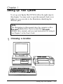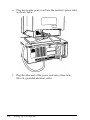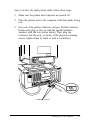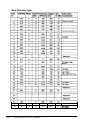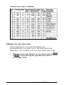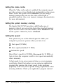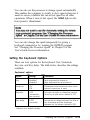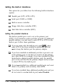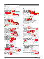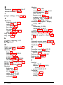
1
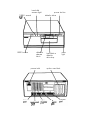
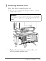
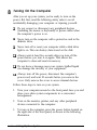
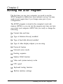
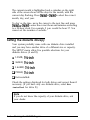
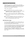
EPSON
®
®
EQUITY 386/33 PLUS
Setup Guide
IMPORTANT NOTICE
DISCLAIMER OF WARRANTY
Epson America makes no representations or warranties, either express or implied, by or
with respect to anything in this manual, and shah not be liable for any implied warranties
of merchantability and fitness for a particular purpose or for any indirect, special, or
consequential damages. Some states do not allow the exclusion of incidental or
consequential damages, so this exclusion may not apply to you.
COPYRIGHT NOTICE
All rights reserved. No part of this publication may be reproduced, stored in a retrieval
system, or transmitted, in any form or by any means, electronic, mechanical,
photocopying recording or otherwise, without the prior written permission of Epson
America, Inc. No patent liability is assumed with respect to the use of information
contained herein. Nor is any liability assumed for damages resulting from the use of the
information contained herein Further, this publication and features described herein are
subject to change without notice.
TRADEMARKS
Epson is a registered trademark of Seiko Epson Corporation
Equity is a registered trademark of Epson America, Inc.
General notice: Other product names used herein are for identification purposes only and
may be trademarks of their respective companies.
Copyright © 1992 by Epson America, Inc.
Torrance, California
ii
Y74099100400
Important Safety Instructions
1. Read all of these instructions and save them for later reference.
2. Follow all warnings and instructions marked on the product.
3. Unplug this product from the wall outlet before cleaning. Use a
damp cloth for cleaning, not liquid cleaners or aerosol cleaners.
4. Do not use this product near water.
5. Do not place this product on an unstable cart, stand, or table.
6. Slots and openings in the cabinet and the back or bottom are
provided for ventilation; these openings must not be blocked or
covered. This product should never be placed near or over a
radiator or heat register.
7. This product should be operated from the type of power source
indicated on the marking label. If you are not sure of the type of
power available, consult your dealer or local power company.
8. Connect all equipment to properly grounded (earthed) power
outlets. If you are unable to insert the plug into the outlet,
contact your electrician to replace your obsolete outlet. Avoid
using outlets on the same circuit as photocopiers or air control
systems that regularly switch on and off.
9. Do not locate this product where the cord will be walked on.
10. If an extension cord is used with this product, make sure that the
total of the ampere ratings on the products plugged into the
extension cord do not exceed the extension cord ampere rating.
Also, make sure that the total of all products plugged into the
wall outlet does not exceed 15 amperes.
11. Never push objects of any kind into this product through the
cabinet slots. Never spill liquid of any kind on the product.
...
111
12. Except as specifically explained in the User’s Guide, do not
attempt to service this product yourself. Refer all servicing to
qualified service personnel.
13. Unplug this product from the wall outlet and refer servicing to
qualified service personnel under the following conditions:
A. When the power cord or plug is damaged.
B. If liquid has entered the product.
C. If the product does not operate normally when the operating
instructions are followed. Adjust only those controls that are
covered by the operating instructions, since improper
adjustment of other controls may result in damage and will
often require extensive work by a qualified technician to
restore the product to normal operation.
D. If the product has been dropped or the cabinet has been
damaged.
E. If the product exhibits a distinct change in performance.
iv
Importantes Mesures de S&wit6
1. Lire attentivement les instructions qui suivent. Les conserver en
lieu siIir.
2. Observer les avertissements et suivre rigoureusement les
instructions marquees sur l’ordinateur.
3. Debrancher l’appareil avant de le nettoyer. Se servir d’un chiffon
humide, sans detergents ni aerosols.
4. Ne pas se servir de l’ordinateur p&s de l’eau.
5. Ne pas placer l’appareil sur un meuble instable.
6. Les ouvertures et fentes a l’arri&re et au dessous du coffre en
assurent la ventilation. 11 est important de ne pas couvrir ni
bloquer ces prises d’air. De m&me, il ne faut jamais placer
l’ordinateur pres dun appareil de chauffage.
7. N’utiliser comme type de courant que celui qui est indique sur
l’etiquette. En cas de doute, consultez votre distributeur ou la
compagnie &ctrique de votre secteur.
8. Toutes les connexions electriques doivent &r-e des connexions de
&mite, avec contact de terre. Si la fiche de s&write n’entre pas
dans le socle de prise de courant, demander a un Gctricien de
remplacer l’ancien socle par un socle neuf. Eviter de brancher
l’ordinateur sur le meme circuit que des machines qui se
mettent en marche et s’arretent tour a tour, telles que
photocopieurs ou climatiseurs.
9. Ne pas laisser de fils ou cordons klectriques dans un lieu de
passage; eviter de leur marcher dessus.
V
10. S’il est nkcessaire d’employer un cordon prolongateur pour
brancher l’appareil, s’assurer que la consommation d’energie
totale des machines branch&s sur le cordon prolongateur ne
depasse pas la capacite en amperes dudit cordon. L’amperage
total de toutes les pieces branch6es sur le socle ne doit pas
d&passer 15 amperes.
11. Ne jamais rien introduire dans les prises d’air. Ne pas renverser
de liquide sur l’appareil.
12. Sauf dans les cas spkcifiquement indiques dans le Guide de
l’utilisateur, ne pas essayer de &parer l’ordinateur &-m&me;
s’adresser a un sp&aliste quahfi&
13. Debrancher l’appareil et s’adresser au personnel de service
qualifie dans les cas suivants:
A. Lorsque le cordon, les broches, la prise ou le socle sont
endommages.
B. Lorsqu’un liquide a p&&tre a l’intkieur de l’appareil.
C. Lorsque l’ordinateur ne r&pond pas normalement aux
commandes pass&s en suivant les instructions. Ajuster
uniquement les controles d&its dans les instructions; il est
possible de gravement endommager l’appareil en touchant
les autres, ce qui pourrait nkcessiter l’intervention dun
technicien qualifie pour le remettre en &at de marche.
D. Lorsque l’appareil est tombe ou le coffre a et& endommage.
E. Lorsque la performance de l’ordinateur est nettement
infkieure a I’ordinaire.
vi
hard disk
access light
TURBO speed
power button
diskette drive
I
I
light Kt-tl
RESET button
diskette
release
latch
hard disk or
diskette
drive bay
option card slots
power inlet
port
power
light
Introduction
Optional Equipment . . . . . . . . . . . . . . . . . . . . . .
Installing Operating Systems and Other Software . . . . .
VGA Utilities . . . . . . . . . . . . . . . . . . . . . . . . . .
How to Use This Manual . . . . . . . . . . . . . . . . . . .
Where to Get Help . . . . . . . . . . . . . . . . . . . . . . .
Chapter 1
.
.
.
.
.
.
.
.
.
.
.
.
.
.
.
Setting Up Your System
1 Choosing a Location . . . . . . . . . . . . . . . . . . . . . . .
2 Removing the Protective Card . . . . . . . . . . . . . . . . .
3 Connecting a Monitor . . . . . . . . . . . . . . . . . . . . . .
Using the VGA Interface . . . . . . . . . . . . . . . . . . .
Using a Display Adapter Card . . . . . . . . . . . . . . . .
4 Connecting a Printer or Other Device . . . . . . . . . . . . .
Using the Parallel Interface . . . . . . . . . . . . . . . . . .
Using the Serial Interface . . . . . . . . . . . . . . . . . . .
5 Connecting the Keyboard . . . . . . . . . . . . . . . . . . . .
6 Connecting the Mouse . . . . . . . . . . . . . . . . . . . . . .
7 Connecting the Power Cord . . . . . . . . . . . . . . . . . . .
8 Turning On the Computer . . . . . . . . . . . . . . . . . . . .
Turning Off the Computer . . . . . . . . . . . . . . . . . .
Chapter 2
2
2
3
3
4
1-1
1-3
1-4
1-4
1-7
1-8
1-8
1-11
1-12
1-13
1-15
1-16
1-18
Running the SETUP Program
Starting the SETUP Program
Selecting Options. . . .
Setting the Date and Time .
Setting the Diskette Drive(s)
.
.
.
.
.
.
.
.
.
.
.
.
.
.
.
.
.
.
.
.
.
.
.
.
.
.
.
.
.
.
.
.
.
.
.
.
.
.
.
.
.
.
.
.
.
.
.
.
.
.
.
.
.
.
.
.
.
.
.
.
.
.
.
.
.
.
.
.
.
.
.
.
.
.
.
.
.
.
.
.
2-2
2-3
2-3
2-4
vii
Setting the Hard Disk Drive(s) . . . . . . . . . . . . . . . . . . .
Hard Disk Drive Types . . . . . . . . . . . . . . . . . . . .
Setting the Primary Display Type . . . . . . . . . . . . . . . . .
Setting the Password . . . . . . . . . . . . . . . . . . . . . . . .
Changing or Deleting a Password . . . . . . . . . . . . . .
Setting Network Server Mode . . . . . . . . . . . . . . . . . . .
Setting the Booting Sequence . . . . . . . . . . . . . . . . . . .
Setting the Extended Setup Options . . . . . . . . . . . . . . .
Setting the Memory and Speed Options . . . . . . . . . .
Setting the Keyboard Options . . . . . . . . . . . . . . . .
Setting the Built-in Interfaces . . . . . . . . . . . . . . . . .
Saving Your Settings . . . . . . . . . . . . . . . . . . . . . . . .
...
‘0111
2-5
2-5
2-8
2-10
2-11
2-11
2-12
2-12
2-13
2-15
2-16
2-18
Introduction
®
®
The Epson Equity 386/33 PLUS is a high-performance
personal computer which offers exceptional speed and
convenience in a compact design.
Your 33 MHz, 80386DX system includes 4MB of internal
memory, a built-in VGA (video graphics array) display
®
adapter, built-in parallel and serial interfaces, and an IBM
PS/2™ compatible mouse port. With these interfaces, you can
connect most of your peripheral devices directly to the
computer, without installing option cards.
The Equity 386/33 PLUS also has four option slots (three 16-bit
and one 8-bit) in which you can install additional devices, such
as a modem or a network card. It can support up to three
internal drives: either two diskette drives and one hard disk
drive, or one diskette drive and two hard disk drives.
The alternate VGA feature connector provides an interface to
connect an optional high-resolution graphics adapter card. This
allows you to use the special graphics features on the adapter
card while accessing the standard VGA signals provided by
your main system board.
Your system offers 128KB of shadow RAM to speed up
processing by moving the ROM BIOS and video ROM into the
RAM area of memory. Additionally, the 64KB of cache memory
lets the computer copy portions of memory into a high-speed
cache buffer so it can access programs and data very quickly.
Optional Equipment
You can easily upgrade your computer by installing additional
memory and adding just about any optional device that is
™
compatible with the IBM Personal Computer, PC XT , or
PC AT™.
By adding 4MB single inline memory modules (SIMMs) to the
main system board, you can expand the computer’s memory
up to 16MB.
You may want to install an 80387DX, 33 MHz or 3167, 33 MHz
math coprocessor in your computer to speed up mathematical
calculations in certain application programs.
Check with your authorized Epson dealer for information on
optional equipment. Instructions for installing options are
provided in the User’s Guide.
Installing Operating Systems and Other Software
®
You probably have a version of MS-DOS to use with your
computer. However, you can use another operating system
®
®
®.
such as OS/2 , UNIX , or XENIX This manual covers basic
operating instructions for using your computer, but does not
explain how to install or use the operating system. Refer to the
documentation that came with your operating system to install
and run it on your computer.
Once you install an operating system, you can use virtually any
application program designed for the IBM PC, PC XT, PC AT,
or compatible computers on your Equity 386/33 PLUS. You
®
may also use powerful 32-bit software such as Microsoft
Windows™ 3.0.
2 Introduction
VGA Utilities
Your Equity 386/33 PLUS comes with special VGA device
drivers and utilities for use with the built-in VGA adapter.
With these utilities, you can take advantage of extended VGA
features such as 16-color graphics mode resolutions up to
1024 x 768 (non-interlaced), 256-color resolutions up to
640 x 480, and 132-column text mode. Instructions for
installing the VGA device drivers and utilities are provided in
the VGA Utilities Guide.
How to Use This Manual
This manual explains how to set up your computer. Chapter 1
provides simple step-by-step instructions for setting up your
system and connecting peripheral devices such as the monitor,
mouse, and printer.
Chapter 2 describes how to run the SETUP program to define
your computer’s configuration. Do this before you use your
computer. You may need to do it again later, if you change the
configuration.
Once you complete the procedures in the manual, see the
User’s Guide for instructions on using your computer.
Introduction 3
Where to Get Help
If you purchased your computer in the United States, Epson
America provides local customer support and service through a
nationwide network of authorized Epson dealers and Service
centers.
Epson also provides the following support services through the
Epson Customer Resource Center at (800) 922-8911:
Technical assistance with the installation, configuration,
and operation of Epson products
Assistance in locating your nearest Authorized Epson
Reseller or Service Center
Sales of ribbons, supplies, parts, documentation, and
accessories for your Epson product
Customer Relations
Epson technical information library fax service
Product literature with technical specifications on our
current and new products.
If you purchased your computer outside of the United States,
please contact your dealer or the marketing location nearest
you for customer support and service. International marketing
locations are listed on the inside back cover of the User’s Guide.
4 Introduction
Chapter 1
Setting Up Your System
To set up your Equity 386/33 PLUS, follow the eight steps in
this chapter. You may want to open this manual’s back cover
foldout so you can refer to the illustrations identifying the
different parts.
Note
The illustrations in this manual show the computer with a
5%inch diskette drive. If your system has a 3lh-inch
diskette drive instead, and you need instructions for using it,
see Chapter 1 in the User’s Guide.
1
Choosing a location
Setting Up Your System
1-1
Before you set up your computer, choose a convenient location
that provides the following:
cl A sturdy desk or table strong enough to support the weight
of your system and its components.
P A flat, hard surface. Soft surfaces like beds and carpeted
floors attract static electricity, which can erase data on your
disks, damage the computer’s circuitry, and prevent proper
ventilation.
D Good air circulation. Leave several inches of space around
the computer so air can move freely.
Ll Moderate environmental conditions. Select a cool, dry area
and protect your computer from extremes in temperature,
humidity, dust, and smoke. Avoid direct sunlight or other
sources of heat.
P Appropriate power sources. To prevent static charges,
connect all your equipment to three-hole, 120-volt, grounded
outlets. You need one outlet for the computer, one for the
monitor, and additional outlets for a printer and any other
peripheral devices.
cl No electromagnetic interference. Do not place your system
too close to any electrical device, such as a telephone, which
generates an electromagnetic field.
1-2
Setting Up Your System
2
Removing the Protective Card
If you have a 5V&nch diskette drive, there is a protective card
in the diskette slot. To remove it, flip the latch up to pop the
card out part way, as shown below; then pull it out.
(If you have a second 5Winch diskette drive, be sure to remove
the card from it.)
Caution
Never turn on your computer with a protective card in the
diskette slot. You could damage the diskette drive.
Save the protective card. If you transport your computer later,
insert the card to protect the drive’s read/write heads during
shipping.
Setting Up Your System
1-3
3
Connecting a Monitor
The way you connect your monitor to the computer depends
on the type of monitor you have. If you have a VGA monitor
(or a multifrequency monitor with an analog connector), you
can connect it to the computer’s built-in VGA port as described
below. If you have any other type of monitor, see “Using a
Display Adapter Card” on page 1-7.
Using the VGA Interface
Follow these steps to connect your VGA monitor to the VGA
port on the computer:
1. Make sure your monitor and computer are turned off.
2. Place your monitor on top of or near the computer. Turn the
monitor and computer around so the backs are facing you.
3. If your monitor does not have an attached cable, connect the
monitor cable to it.
1-4
Setting Up Your System
4. Examine the connector end of the monitor cable, and position
the plug to line up with the monitor port on the computer
(marked with a monitor icon). Then insert the plug into the
port, as shown below.
Caution
To avoid damaging the connector, be careful not to bend
the pins when inserting the plug.
5. If the connector has retaining screws, be sure to tighten them.
Setting Up Your System
1-5
6. Plug the monitor power cord into the monitor’s power inlet,
as shown below.
7. Plug the other end of the power cord into a three-hole,
120-volt, grounded electrical outlet.
1-6
Setting Up Your System
Using a Display Adapter Card
If you are using a non-VGA monitor, you’ll need to install a
display adapter (video) card in one of the computer’s option
slots before you can connect the monitor. (Your dealer may
have already installed the video card for you.)
If the video card has not yet been installed, follow the
instructions in Chapter 4 of the User’s Guide to install an option
card. But first, check the following table to make sure your
display adapter card and monitor are properly matched.
Monitor/video card compatibility
Monitor
Video Card
Monochrome
Monochrome display adapter (MDA)
Multi-mode graphics adapter (MGA)
Enhanced graphics adapter (EGA)
Hercules® graphics card
CGA
Color graphics adapter (CGA)
Multi-mode graphics adapter (MGA)
Enhanced graphics adapter (EGA)
EGA
Enhanced graphics adapter (EGA)
Monochrome or color VGA
Video graphics array (VGA)
Extended VGA
Super VGA adapter
installing the video card, check to make sure any
switches or jumpers on the card are set properly. For example,
you may need to change a switch setting to select color or
monochrome. See the documentation that came with your
monitor or video card for instructions.
When
If you install a high-resolution graphics adapter card for your
VGA monitor, you can still take advantage of the computer’s
built-in VGA capabilities. See Chapter 4 of the User’s Guide for
instructions on using the alternate VGA connector with your
graphics adapter card.
Setting Up Your System
1-7
Note
If you install a display adapter card, you must set jumper J1
on the main system board to disable the built-in VGA
interface so that your card can operate as the primary
display adapter. You may also need to set jumper J4 to
indicate whether a color or monochrome monitor is
installed. See Chapter 4 of the User’s Guide for instructions
on changing jumper settings.
Once you have installed your video card, return to this section
to connect your monitor to the computer. If your monitor came
with its own manual, follow the instructions there. Otherwise,
you can follow the steps in “Using the VGA Interface” on
page 1-4; just insert your monitor connector into the video card
port instead of the built-in VGA port.
4
Connecting a Printer or Other Device
Your computer has both parallel and serial interfaces. To
connect a printer or other peripheral device to one of these
interfaces, follow the instructions below.
Using the Parallel lnterface
®
The parallel interface on your computer is Centronics
compatible and uses a DB-25S connector.
To connect your printer and computer, you need an IBM
compatible printer cable. If you are not sure which cable you
need, check with your Epson dealer.
1-8
Setting Up Your System
Once you have the right printer cable, follow these steps:
1. Make sure the printer and computer are turned off.
2. Place the printer next to the computer with their backs facing
you.
3. One end of the printer cable has a 25-pin, D-shell connector.
Position the plug to line up with the parallel interface
(marked with the icon shown below). Then plug the
connector into the port, as shown. If the plug has retaining
screws, tighten them by hand or with a screwdriver.
retaining screws
Setting Up Your System
1-9
4. Connect the other end of the cable to the printer as shown
below. To secure the cable, squeeze the clips at each side of
the printer port and push them into place.
clips
5. Plug the printer’s power cord into a three-hole, 120-volt,
grounded electrical outlet.
1-10
Setting Up Your System
Using the Serial Interface
If you have a printer, a modem, or other peripheral device with
a serial interface, you can connect it to the serial (BS-232C) port
on the back of the computer.
The serial port uses a DB-9P connector, so be sure you have a
compatible cable. To connect a serial device, follow the same
steps as above for connecting a parallel device, but insert the
connector into the serial port, marked with the icon shown
below.
Note
You need to ensure that the serial port is set up so it
functions properly. If you are using the port for a serial
printer, you need to redirect printer output to the serial port
instead of the parallel port. If you using MS-DOS, you can
do this with the MODE or SETMODE commands. See your
MS-DOS manual for instructions.
Setting Up Your System
1-11
5
Connecting the Keyboard
Follow these steps to connect the keyboard:
1. Make sure the computer is turned off.
2. Hold the keyboard cable connector so the arrow on the
connector faces up. Insert it into the port marked with a
keyboard icon, as shown below.
Caution
Although the connectors and ports for the keyboard and
mouse are physically identical, they cannot be used
interchangeably. Be sure to plug the keyboard into the
keyboard port.
1-12
Setting Up Your System
3. You can change the angle of the keyboard by adjusting the
legs on the bottom. Turn it over and flip each leg upward
until it locks into place, as shown below.
6
Connecting the Mouse
Your computer has an auxiliary port for an IBM PS/2
compatible mouse that uses a round, miniature DIN (6-pin)
connector. If your mouse has this type of connector, you can
connect it to the built-in port on your computer. If your mouse
requires a different interface port, you can connect it to the
built-in serial port or install an option card to provide the
interface.
To connect a mouse to the built-in mouse port, make sure your
computer is turned off. Then plug the connector into the port
marked with a mouse icon, as shown in the following
illustration.
Setting Up Your System
1-13
mouse connector
Caution
Although the connectors and ports for the mouse and
keyboard are physically identical, they cannot be used
interchangeably. Be sure to plug the mouse connector into
the mouse port.
Once you have connected a mouse, you may need to add
commands to your MS-DOS CONFIG.SYS file (or equivalent) to
enable your computer to use a mouse. See your operating
system and mouse manuals for instructions.
Note
If you want to use a mouse or other pointing device
connected to an option card in your computer, disable the
built-in mouse connector by changing the setting of jumper
J2. See Chapter 4 of the User’s Guide for instructions.
1-14
Setting Up Your System
1
7
Connecting the Power Cord
Follow these steps to connect the power cord:
1. Plug the power cord into the AC power inlet on the back
panel, as shown below.
WARNING
To avoid generating an electric shock, be sure to plug the
cord into the computer before plugging it into the wall
socket.
2. Plug the other end of the power cord into a three-hole,
120-volt, grounded electrical outlet.
Setting Up Your System
1-15
8
Turning On the Computer
After you set up your system, you’re ready to turn on the
power. But first, read the following safety rules to avoid
accidentally damaging your computer or injuring yourself:
Cl Do not connect or disconnect any peripheral devices
(including the mouse or keyboard) or power cables when
the computer’s power is on.
Q Never turn on the computer with a protective card in the
diskette drive.
CI Never turn off or reset your computer while a disk drive
light is on. This can destroy data stored on the disk.
Q Always wait at least five seconds after you turn off the
power before you turn it on again. This allows the
computer to clear and reset its memory.
0 Do not leave a beverage near your system. Spilled liquid
can damage the circuitry of your equipment.
D Always turn off the power, disconnect the computer’s
power cord, and wait 30 seconds before you remove the
cover. Only remove the cover to access internal devices.
Follow these steps to turn on your system:
1. Turn your computer around so the front panel faces you and
place your other system components in a convenient
arrangement.
2. Turn on the monitor, printer, and any other peripheral
devices connected to the computer.
3. To turn on the computer, press the power button located on
the right side of the front panel, as shown in the following
illustration.
1-16
Setting Up Your System
power button
The power indicator next to the button lights up. After a few
seconds, the computer counts the amount of memory, and then
performs a diagnostic self test. This is a series of checks the
computer completes each time you turn it on to make sure
everything is working correctly.
If necessary, use the controls on your monitor to adjust the
brightness and contrast until characters on the screen are clear
and at a comfortable level of intensity. If your monitor has
horizontal and vertical hold controls, you may need to use
them to stabilize the display.
Note
If you or your dealer has made a major change to your
system, such as adding a disk drive, you may need to wait a
few minutes for your computer to complete power-on
diagnostics the first time you turn it on.
When the system has successfully completed its self test, you
see the following prompt:
Press <DEL> to start SETUP
Setting Up Your System
1-17
Do not press any key yet. (If MS-DOS is already installed on
your system, you will see a prompt to enter the date.) Turn off
the computer as described below.
If there is no operating system on your computer, you see an
error message. Ignore the message for now. Follow the
instructions below to turn off the computer.
Note
If your computer’s configuration does not match the
information stored in the computer’s CMOS RAM (defined
through the SETUP pro am), you see an error message and
a prompt to press the &
F1 key. Press [ to continue.
Then run the SETUP program to correct the information.
(See Chapter 2 for instructions.)
Turning Off the Computer
Whenever you turn off your system, follow these steps:
1. Save your data and exit any application program you are
using.
2. Check the hard disk drive light and the diskette drive light(s)
to make sure they are not on. Do not turn off the computer
if a drive light is on.
3. Remove any diskette(s) from the diskette drive(s).
4. Press the power button to turn off the computer and then turn
off any peripheral devices (monitor, printer, etc.).
Now go on to Chapter 2 and follow the instructions to run the
SETUP program. When you finish running SETUP, you must
install an operating system before you can run your application
software. See your operating system manual for instructions.
1-18
Setting Up Your System
Chapter 2
Running the SETUP Program
The first time you use your computer, you need to run the
SETUP program to define how your system is set up. You may
need to run it again later if you change some part of your
configuration.
The SETUP program is stored in the computer’s read only
memory (ROM), so you can run the program any time you turn
on or reset your computer. SETUP lets you verify or change the
following:
Current date and time
Type of diskette drives(s) installed
Type of hard disk drive(s) installed
Type of video display adapter you are using
Password feature
Network server mode
Booting sequence
Shadow RAM function
Video and system memory cache
CPU speed
Keyboard testing function
Built-in interface settings.
Running the SETUP Program
2-1
The configuration you define through SETUP is stored in a
special area of memory called CMOS RAM. This memory is
backed up by a battery, so it is not erased when you turn off or
reset the computer. Whenever you reboot the computer, it
checks the settings, and if it discovers a difference between the
information in the CMOS RAM and its actual hardware
configuration, it prompts you to run SETUP. You see a message
such as the following:
CMOS memory size mismatch
RUN SETUP UTILITY
Press 01~ to RESUME
If this happens, press [ to run SETUP and correct the
setting.
Starting the SETUP Program
To start SETUP, make sure there is no diskette in the diskette
drive; then turn on your computer. (If the computer is already
on, press the RESET button on the front panel to reset it.) After
the self test, you see the following prompt:
Press <Del>
to
start SETUP
As soon as you see this message, press the @@l key. If you do
not press t5
aetate within five seconds, the computer starts
loading the operating system and you will not be able to run
SETUP. If this happens, reset the computer and try again.
You see the following options:
Start operating system
Run SETUP
2-2
Running the SETUP Program
The first option is highlighted. Press m to highlight
Run SETUP, and then press m. The SETUP menu appears
on the screen.
The menu automatically displays the base memory size, the
extended memory size, and whether a math coprocessor
(numeric processor) is installed. Additionally, the SETUP menu
lists the parameters you can change.
Selecting Options
A solid cursor bar highlights the parameter currently selected.
You can scroll through the parameters using the four arrow
[11). When you reach a
keys Cm, m.d
t
parameter you want to change, press &&J or m to display
and select the available options.
An information window at the bottom of the menu describes
the options available or any other keys you can press to change
the highlighted parameter.
The rest of this chapter describes how to choose the correct
SETUP parameters for your system.
Setting the Date and Time
The real-tune clock in your computer continously tracks the
date and time-even when the computer is turned off. Once
you set the date and time using SETUP, you should not need to
change either parameter, unless you need to adjust the time for
daylight savings. (The computer automatically changes the
date for leap years.)
Running the SETUP Program
2-3
The current month is highlighted and a calendar on the right
side of the screen shows all the days for the month, with the
current day flashing. Press m or &@ to select the correct
month, day, and year.
To change the time. move the cursor to the next line and press
Issue] 0; [$ to enter the correct hour and minutes according
to a 24-hour clock. For example, 5 p.m. would be hour 17. You
cannot set the number of seconds.
Setting the Diskette Drive(s)
Your system probably came with one diskette drive installed
and you may have another drive of a different size or capacity.
The SETUP menu offers five possible selections for your
diskette drives (A and B):
P 1.2MB, 5VGnch
D 360KB, 5%inch
Cl 1.44MB, 3M-inch
0 720KB, 31R-inch
LI Not installed.
Check the settings displayed for both drives and correct them if
necessary. (If you have only one diskette drive, select Not
installed for drive B.)
Note
If you do not know the capacity of your diskette drive, ask
your dealer.
2-4
Running the SETUP Program
Setting the Hard Disk Drive(s)
The SETUP program lets you select the type of hard disk
drive(s) installed in your computer. If you have two hard disk
drives, the first one is C and the second one is D. Be sure to
choose the correct setting for both drives.
Follow these guidelines:
0 If your system does not have a hard disk, select Not
installed for drives C and D. If you have only one hard
disk drive, select Not installed for drive D.
Q If your computer came with an Epson 120MB hard disk
drive (or if you installed this drive yourself), select number
39 for drive C.
P
If you have installed another type of hard disk drive, you
need to select the drive type number that matches your
drive. See “Hard Disk Drive Types” below.
Hard Disk Drive Types
If you have installed a hard disk in your computer that is not
the standard Epson 120MB drive (type 39), you need to select
the correct type number to match your drive.
The following table lists the types of standard hard disk drives
you can use. Check this table and the documentation supplied
with your hard disk to find the correct type number for your
drive. (Your drive’s documentation should list all the
parameters necessary to identify it in this table.) If none of the
types listed matches your drive, see “Defining your own drive
type,” below.
Running the SETUP Program
2-5
Hard disk drive types
2-6
32
1023
5
17
33
901
5
53
Running the SETUP Program
none
none
1023
42
900
117
L!JS12OAT
Hard disk drive types (continued)
Defining your own drive type
If the parameters for your hard disk (listed in its
documentation) do not match any of the types listed in the
table above, you can define your own type. Follow these steps:
1. With the cursor at the Hard disk type option, press @&
or (PgDn] to scroll through the types until you come to
47 = USER TYPE.
Running the SETUP Program
2-7
2. Use the numeric keys to enter the appropriate values for these
parameters:
Cyln
= the number of cylinders on the disk.
Head
= the number of read/write heads in the drive.
WPCO~ = the precompensation cylinder.
LZone = the landing zone (the area on which the computer
parks the heads when you run the HDSIT program).
Set
= the number of sectors on the disk.
Size
= the total amount of storage capacity for the disk
(selectedautomatically).
Press m after typing each number. If you enter an invalid
number, the computer beeps and does not go on to the next
parameter. Check your drive documentation and try again. You
do not enter a value for size; SETUP does this automatically
based on the other values you have entered.
Setting the Primary Display Type
This option lets you define the type of adapter you are using
for your primary display device:
Q VGA or EGA
c3 Color 80 x 25
D Monochrome
Q Color 40 x 25.
2-8
Running the SETUP Program
If you have connected your monitor to the computer’s built-in
VGA port, select VGA or EGA. If you installed an optional
video card, follow these guidelines to select the correct adapter
type:
D If you have a VGA adapter card or an enhanced graphics
adapter (EGA) card, select VGA or EGA.
P If you have a color graphics adapter (CGA) or a
multi-mode graphics adapter (MGA) attached to an RGB
(color) monitor, select Color 80x25. (Also be sure to set
the color/mono switch on the MGA card to color.)
Q If you have a monochrome display adapter (MDA), an
MGA, or a Hercules MGA attached to a monochrome
monitor, choose Monochrome. (Also remember to set the
color/mono switch on the MGA card to mono.)
D If you have a composite color monitor, such as a color
television with a video input, try selecting Color 80x25.
If the monitor’s resolution is poor, run SETUP again and
select Color 40x25.
If you have two display adapters of different types, select the
setting for the one you want to be your primary display
adapter. The other one is your secondary adapter.
If you have installed an EGA or VGA display adapter card, or
another type of card that you want to be the primary display
adapter, you must set jumper J1 on the main system board to
position B to disable the built-in VGA interface.
If you install one type of display adapter card and then change
the type of monitor you are using (from color to monochrome
or vice-versa), you also need to set jumper J4. If you have two
types of cards, set the jumper to match the monitor that is your
primary display. See Chapter 4 in the User’s Guide for
instructions on changing jumper settings.
Running the SETUP Program
2-9
Setting the Password
The SETUP program lets you set an optional password to
control who can use your system. If you do not want to set a
password for your computer, skip this section.
Once you set a password through SETUP, you must enter it
every time you turn on your computer or reset it by pressing
the RESET button. If you do not enter it correctly, you cannot
access your system.
To set a password, move the cursor to the Password option.
Next to it, you see Not installed. (If you have already set a
password you see Installed.) Press b
U ormto
display the following:
New Install
********
Now type the password you want to use. You can type up to
eight characters using the letter or number keys, in upper- or
lowercase. For example, you could enter the following:
123aBcl
You can use the backspace key to correct mistakes. After you
type the password, press d
EIW .
Note
Be sure to remember the password you enter or write it
down and keep it in a safe place. If you cannot remember
it, you will not be able to access the computer the next time
you turn it on. If you forget your password, however, there
is a way to disable the function. See “Password Problems” in
Appendix C of the User's Guide for more information.
2-10
Running the SETUP Program
Changing or Deleting a Password
If you want to change the current password, highlight the
Password option and press Ed
U or (&@ to display New
Install. Then enter a new password, as described above.
To delete the password, press m or [p9Dnl to display Not
installed.
Be sure to save your settings (as described at the end of this
chapter) when you exit the SETUP program.
Setting Network Server Mode
If you will be using your computer as a network server, select
Installed. If you want to use your computer as a stand-alone
workstation, leave this option set to Not Installed.
Note
If you want to use your computer as a network server, you
can set a power-on password to increase the security of your
system and prevent unauthorized users from accessing
system files. See “Setting the Password” above.
Running the SETUP Program
2-11
Setting the Booting Sequence
The booting sequence determines the order in which the
computer reads the drives when it looks for the operating
system.
If you select A: then c : , each time you turn on or reset the
computer, it checks drive A for an operating system diskette
and loads the operating system from that diskette. If drive A
does not contain an operating system diskette, the computer
loads the operating system from drive C. This is the default
setting.
If you select C: only, the computer loads the operating
system from drive C without checking for a diskette in drive A.
Setting the Extended Setup Options
The Extended Setup options control these three features:
Q Memory and speed
CL Keyboard
Q Built-in interfaces.
When you highlight any of these Extended setup options, a
submenu listing the current settings for that option appears at
the right of the screen. To enter this submenu and change a
setting, press I-t]. Use [71 or [11 to highlight the
Dn to
setting you want to change, then press @& or &II
display and select the new setting.
When you finish, press [tl to return to the Main menu.
The following sections describe each of the Extended Setup
options.
2-12
Running the SETUP Program
Setting the Memory and Speed Options
SETUP offers the following options for customizing your
system’s memory and speed settings:
0 BIOS shadow
D Video shadow
Q Video cache
D Cache
D speed.
Each of these options is described below.
Setting the BIOS and video shadow options
Your computer can access RAM (random access memory)
faster than ROM (read only memory). The BIOS and video
shadow RAM options enable the Equity 386/33 PLUS to copy
the contents of its system BIOS and video ROM into RAM to
speed up certain operations. You can enable or disable both
options, depending on your needs.
Leave the BIOS shadow option set to Enabled unless you have
installed a memory card that provides its own shadow RAM.
Leave the Video shadow option set to Enabled unless you
have installed a video card that provides its shadow RAM.
Running the SETUP Program
2-13
Setting the video cache
When the Video cache option is enabled, the computer speeds
up video access so it can display text and graphics on the screen
faster. Leave this option set to Disabled if you are using a
memory manager that can use the video cache RAM as
expanded memory. (See your memory manager documentation
for more information).
Setting the system memory caching
The Equity 386/33 PLUS provides a 64KB cache area of
memory where it can access data faster than standard memory.
If you do not want to use this feature, select Disabled for the
Cache option. Otherwise, leave it Enabled.
Setting the speed
This option lets you set the default speed at which your
computer’s processor operates when you turn it on:
P Fast speed (33 MHz)
0 Slow speed (simulated 11 MHz)
0 Automatic speed.
Select Fast speed for 33 MHz, Slow speed for 11 MHz, or
Auto to have the computer switch to low speed automatically
when necessary.
At fast speed, it can access memory faster, so your programs
work faster. Select Fast unless you are using an application
program that requires the slower speed. Some programs
(especially older ones) have specific timing requirements when
accessing diskettes. Check your application program manual.
2-14
Running the SETUP Program
You can also set the processor to change speed automatically.
This enables the computer to switch to slow speed whenever it
needs to access a diskette but run at fast speed for all other
operations. When it runs at fast speed, the TURBO light on the
front panel is illuminated.
You may not want to use the Automatic setting for certain
copy-protected programs. See “Changing the Processor
Speed” in Chapter 2 of the User’s Guide for more information.
s
You can also change the speed temporarily by giving a
keyboard command or by running the ESPEED program.
See “Changing the Processor Speed” in Chapter 2 of the
User’s Guide for more information.
Setting the Keyboard Options
There are four options for the keyboard: Test, NumLock,
Key rate, and Key delay. The table below describes the settings
available.
Keyboard options
l
Option
Settings
Description
Test
Enabled*
Disabled
Tests keyboard at power-on
Skips keyboard test at power-on
NumLock
On’
Off
Determines initial NumLock status when
system is turned on or reset
Key rate
2-30
(characters
per second)
Sets rate at which a character repeats
when key is held down; default is 10.9
Key delay
0.251
(seconds)
Sets period of delay between the time a
key is pressed and the character
appears on the screen; default Is 0.50.
Indicates the default setting
Running the SETUP Program
2-15
Setting the Built-in Interfaces
This option lets you define how the following built-in interfaces
operate:
0 Parallel port (LPT1, LPT2, LPT3)
D Serial port (COM1 or COM2)
0 Built-in mouse controller
0 Floppy disk drive controller (FDC)
Q Hard disk drive controller (HDC).
Setting the parallel interface
The built-in parallel port is set to act as the primary port
(LPT1). If you install an option card that provides an additional
parallel interface, you may need to select LPT2 or LPT3 for the
built-in port. Follow these guidelines:
0 If you are using only the built-in port, select LPT~. Also
select LPT1 if you have installed an additional port but
want to keep the built-in port the primary adapter.
0 If you have installed an additional port that is pre-set to act
as the primary port or one that you want to be the primary
port, select LPT2. For example, if you have installed an IBM
monochrome adapter/parallel interface card, the parallel
port on the card must be the primary adapter and you need
to select LPT2 for the built-in port.
D If you have installed two additional parallel ports and want
them to be primary and secondary, select LPT3.
0 If you have installed three additional parallel ports and you
do not want to use the built-in port, select Disabled.
2-16
Running the SETUP Program
Note
be sure to set any jumpers on the card(s) to indicate how you
want the port to be recognized (LPT1, LPT2, or LPT3).
Setting the serial interface
The built-in serial port in your computer is set to act as the
primary port (COM1). If you install an option card that
provides an additional serial port, that port automatically
becomes secondary (COM2). However, if you want the port on
the card to be COM1, select COM2 for the built-in port.
If you install a card (or cards) that provides two additional
serial ports and you want them to act as the primary and
secondary ports, select Disabled for the built-in port. Also, be
sure to set any jumper(s) on the card(s) to indicate whether you
want the port(s) to be primary or secondary.
Setting the mouse controller
If you are using the built-in mouse port, the PS/2 mouse option
should be set to Enabled. If you are using a mouse or other
pointing device connected to an option card in your computer,
set this option to Disabled.
Setting the disk drive controllers
If you are using the standard drives that came with your
computer, the hard disk drive controller (HDC) and diskette
drive controller (FDC) should be set to Enabled.
However, if you install an option card to provide a controller
for a diskette drive or hard disk drive, you need to select
Disabled.
Running the SETUP Program
2-17
Saving Your Settings
After you have made your selections for SETUP, press m to
exit. You see the following prompt:
Save SETUP configuration (Y/N)?
Press m to return to the menu to make corrections. Press
[vl and m to save the settings in the CMOS RAM. To exit
SETUP without saving your changes press [Nl and [Ena).
If you saved your changes, the SETUP program resets your
system and the computer runs through its power-on diagnostic
tests.
If something is wrong, however, you see an error message and
a prompt to run SETUP. Follow the instructions on the screen
to run SETUP again to correct it. (You may need to reset the
computer.)
If you have just run SETUP for the first time, the next thing you
need to do is install the operating system on your computer.
See your operating system manuals for instructions.
2-18
Running the SETUP Program
I n d e x
A
D
AC power inlet, 1-15
Alternate VGA feature connector,
Intro-l, 1-7
Analog connector, 1-4
Application program, Intro-2
Automatic speed, 2-14-15
Date, setting, 2-4
Deleting password, 2-11
Device drivers, Intro-3
Diagnostics, power-on, l-17, 2-18
Diskette drive,
configuring, 2-4
controller, 2-16-17
light, 1-16, 1-18
type, 2-4
Display adapter, 1-7-8, 2-8-9
Display type, 1-7-8, 2-8-9
Drives, see Diskette drive or
Hard disk
B
Base memory, 2-3
Battery, 2-2
BIOS shadow, 2-13
Booting sequence, 2-1, 2-12
Built-in interfaces, Intro-1, 2-1,
2-12, 2-16-17
C
Cache memory, Intro-l, 2-13-14
Centronics, 1-8
CGA adapter, l-7, 2-8-9
Changing password, 2-11
Clock, setting, 2-3-4
CMOS RAM, 1-18, 2-2, 2-18
Color graphics adapter, 1-7, 2-8-9
COMn, 2-16-17
CONFIG.SYS, 1-14
Configuration, 1-18, 2-2
Connecting,
keyboard, 1-12
modem, 1-11
monitor, 1-4-8
mouse, 1-13-14
power cord, 1-15
printer, 1-8-11
Customer Resource Center,
Intro-4
Coprocessor, numeric, Intro-2, 2-3
Copy-protected programs, 2-15
CPU speed, 2-1, 2-13-15
Cursor bar, 2-3
E
EGA card, 1-7, 2-8-9
Enhanced graphics adapter, 1-7,
2-8-9
Error messages, 2-2, 2-18
ESPEED, 2-15
Extended memory, 2-3
Extended SETUP options, 2-12-17
Extended VGA adapter, 1-7
F
Fast speed, 2-14-15
Feature connector, VGA, Intro-1,
1-7
Floppy disk controller, 2-16-17
H
Hard disk, (see also Diskette drive)
configuring, 2-5-8
controller, 2-16-17
drive light, 1-16-18
type, 2-5-8
Help, where to get, Intro-4
Hercules display adapter, 1-7, 2-9
Index 1
Interfaces, Intro-l, 2-12, 2-16-17
Internal memory, Intro-l
J
Jumper settings, l-7-8, 1-14, 2-9
K
Keyboard,
adjusting angle, 1-13
cable, 1-12
connecting, 1-12
key delay, 2-15
key rate, 2-15
options, 2-1, 2-12, 2-15
port, 1-12, 1-14
Key delay, 2-15
Key rate, 2-15
L
Location, choosing, 1-1-2
LPTn, 2-16-17
M
Math coprocessor, Intro-2, 2-3
MDA card, 1-7
Memory,
base, 2-3
cache, Intro-l, 2-13-14
extended, 2-3
modules, Intro-2
RAM, Intro-l, 2-2, 2-13-14
shadow, Intro-l, 2-13
MGA display adapter, l-7, 2-9
MODE, 1-11
Modem, connecting, 1-11
Monitor,
brightness, 1-17
cable, 1-4-5
CGA, 1-7, 2-8-9
color, 1-7-8, 2-8-9
connecting, 1-4-8
contrast, 1-17
2
Index
Monitor,
EGA, 1-7, 2-8-9
monochrome, 1-7-8, 2-8-9
multifrequency, 1-4
port, 1-4-6
power cord, 1-6
primary display, 1-8, 2-8-9
selecting type, 1-7-8, 2-8-9
VGA, 1-4, 1-7-8, 2-8-9
Monochrome graphics adapter,
1-7-8, 2-8-9
Mouse,
connecting, 1-13-14
controller, 2-16-17
port, Intro-l, 1-12-14, 2-17
MS-DOS, Intro-2, 1-18, 2-18
Multifrequency monitor, 1-4
Multi-mode graphics adapter, 1-7,
2-9
N
Network server mode, 2-1, 2-11
Numeric coprocessor, Intro-2, 2-3
NumLock, 2-15
O
Operating speed, 2-1, 2-13-15
Operating system, installing,
Intro-2, 2-18
Option cards, Intro-l, 2-8-9
Option slots, Intro-l
OS/2, Intro-2
P
Parallel,
cable, 1-8-10
interface, Intro-1, 1-8-10,
2-16-17
port, l-8-10, 2-16-17
Password,
changing, 2-11
deleting, 2-11
setting, 2-10-11
Port,
keyboard, l-12, 1-14
monitor, 1-4-5
mouse, Intro-1, 1-12, 2-17
parallel, 1-8-10, 2-16-17
serial, 1-11, 1-13, 2-16-17
VGA, 1-4-6, 2-8-9
Power,
button, 1-17-18
cables, 1-16
cord, 1-15
source, 1-2
Power-on diagnostics, 1-17, 2-18
Power-on password, 2-10-11
Precautions, 1-2, 1-16
Primary display adapter, 1-8
Primary port, 2-16-17
Printer,
connecting, 1-8-11
parallel interface, 1-8-10,
2-16-17
power cord, 1-15
redirecting, 1-11
serial interface, 1-11, 2-16-17
Processor speed, 2-1, 2-13-15
Protective card, 1-3, 1-16
R
RAM, Intro-1, 2-2, 2-13-14
Random access memory, Intro-1,
2-2, 2-13-14
Read only memory, 2-1, 2-13
Read/write heads, 1-3
Real-time clock, 2-3
Redirecting printer output, 1-11
Removing protective card, 1-3,
1-16
RESET button, 2-2, 2-9
Resetting computer, 1-16
RGB monitor, 2-9
ROM, 2-1, 2-13
ROM BIOS, Intro-l, 2-13-14
RS-232C, 1-11
S
Secondary display adapter, 2-9
Self test, 1-17, 2-18
Serial,
cable, 1-11
interface, Intro-1, 1-11, 2-16-17
port, 1-11, 1-13, 2-16-17
SETMODE, 1-11
Setting up, 1-1-18
SETUP menu 2-3
SETUP program, 2-1-18
base memory, 2-3
BIOS shadow, 2-13
booting sequence, 2-1, 2-12
built-in interfaces, 2-1, 2-12,
2-16-17
cache, 2-13-14
clock, real-time, 2-3
CPU speed, 2-1, 2-13-15
date, 2-1, 2-3-4
disk drive controllers, 2-16-17
diskette drive types, 2-1, 2-4
display type, 2-1, 2-8-9
error message, 2-2, 2-18
extended memory size, 2-3
extended SETUP options, 2-12-17
floppy disk controller, 2-16-17
hard disk controller, 2-16-17
hard disk drive type, 2-1, 2-5-8
keyboard test function, 2-15
keyboard options, 2-1, 2-12, 2-15
key delay, 2-15
key rate, 2-15
leaving the program, 2-18
math coprocessor, 2-3
memory, 2-3, 2-12-14
mouse controller, 2-16-17
network server mode, 2-1, 2-11
NumLock, 2-15
parallel interface, 2-16-17
password, 2-1, 2-10-11
primary display type, 2-8-9
Index 3
SETUP program,
processor speed, 2-1, 2-13-15
real-time clock, 2-3
saving settings, 2-18
serial interface, 2-16-17
shadow RAM, 2-1, 2-13-15
speed, 2-1, 2-13-15
starting the program, 1-18, 2-2-3
system memory cache, 2-1,
2-13-14
time, 2-1, 2-3-4
video display adapter, 2-1,
2-8-9
video memory cache, 2-1,
2-13-14
video shadow, 2-13
Shadow RAM, Intro-1, 2-1, 2-13
SIMMs, Intro-2
Slow speed, 2-14-15
Software, Intro-2
Speed, 2-1, 2-13-15
Super VGA adapter, 1-7
System,
BIOS, 2-13
memory cache, 2-1, 2-13-14
setting up, 1-1-18
T
V
VGA,
alternate feature connector,
Intro-1, 1-7
color, 1-7-8
device drivers, Intro-3
display adapter, Intro-1, 1-7-8,
2-8-9
extended, Intro-3, 1-7-8
feature connector, Intro-1, 1-7
monitor, 1-4, 1-7-8, 2-8-9
monochrome, 1-7-8
port, 1-4-6, 2-8-9
utilities, Intro-3
Video cards, 1-7-8, 2-1, 2-8-9
Video graphics array, see VGA
Video memory cache, 2-1, 2-13-14
Video monitor, see Monitor
Video ROM, Intro-l, 2-13
Video shadow, 2-13
X
XENIX, Intro-2
Time, setting, 2-1, 2-3-4
TURBO light, 2-15
Turning off computer, 1-18
Turning on computer, 1-16-18
4
U
UNIX, Intro-2
Utilities, VGA, Intro-3
Index