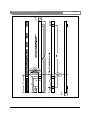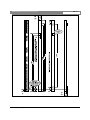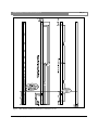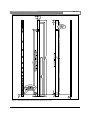
1
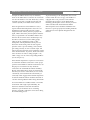
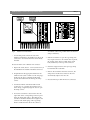
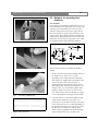
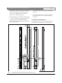
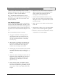
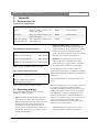
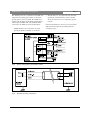
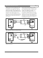
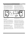
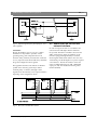
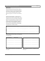
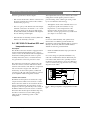
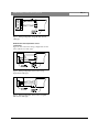
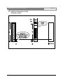
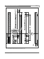
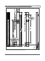
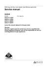
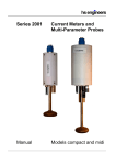
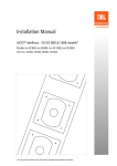
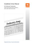
INTELLIVOX DDC
Installation Manual
EN Active Line Array Loudspeakers
LBC 325x Series
EN | 3
Intellivox Active DDC | Nomenclature | Contents
Disclaimer
1. The information in this manual has been carefully
checked for accuracy, but no guarantee is given as
to the correctness.
2. The information in this manual is subject to change
without notice, and does not represent a
commitment on the part of the vendor. Bosch
Security Systems shall not be liable for any loss or
damage whatsoever arising from the use of
information or any error contained in this manual.
3. No part of this manual may be reproduced, stored
in a retrieval system, or transmitted, in any form or
by any means, electronic, electrical, mechanical,
optical, chemical, including photocopying and
recording, for any purpose other than the
purchaser's personal use without the express written
permission of Bosch Security Systems.
4. The unit is designed to operate from AC 50/60 Hz,
115V or 230 V - please, see the label on the unit.
Never connect to any other voltage or frequency.
5. Unplug the product before cleaning. Do not use
liquid cleaners or aerosol cleaners but a damp
cloth.
6. Protect the product from overheating. Do not block
ventilation slots. The product should not be built-in
unless proper ventilation is provided.
7. The purchaser should not attempt to service the
product, as he or she may be exposed to dangerous
voltages. All maintenance and service should be
carried out by Bosch Security Systems or its
authorized agents. Bosch Security Systems cannot
accept any liability for any loss or damage caused
by service, maintenance or repair by unauthorized
personnel.
Bosch Security Systems | July 2003
Table of contents
1.
INTRODUCTION. . . . . . . . . . . . . . . . . . . . .5
2.
2.1
2.2
2.3
2.3.1
2.4
2.5
INSTALLATION GUIDE. . . . . . . . . . . . . . . .6
ITEMS IN THE BOX. . . . . . . . . . . . . . . . . . .6
GENERAL CONSIDERATIONS. . . . . . . . .6
WIRING AND CONNECTIONS. . . . . . . . .8
Mains power. . . . . . . . . . . . . . . . . . . . . . . . . . .8
SIGNAL CONNECTIONS. . . . . . . . . . . . . . .8
METHODS FOR MOUNTING THE
INTELLIVOX. . . . . . . . . . . . . . . . . . . . . . . .10
2.5.1 General. . . . . . . . . . . . . . . . . . . . . . . . . . . . . .10
2.5.2 Measures and dimensions. . . . . . . . . . . . . . . .11
2.5.3 Mounting procedure. . . . . . . . . . . . . . . . . . . .12
3.
3.1
3.2
3.3
3.4
3.5
APPENDIX. . . . . . . . . . . . . . . . . . . . . . . . . .13
REFERENCE PART LIST. . . . . . . . . . . . . . .13
GROUNDING STRATEGY. . . . . . . . . . . . .13
SOME NOTES ON THE RS-485
NETWORK INTERFACE. . . . . . . . . . . . . . .17
AMBIENT SPL AND TEMPERATURE
SENSOR. . . . . . . . . . . . . . . . . . . . . . . . . . . .20
INTELLIVOX DIMENSIONS OF THE
DIFFERENT MODELS. . . . . . . . . . . . . . . .22
Intellivox DDC | Installation Manual | Contents
Figure and Table lists.
Fig
Fig
Fig
Fig
Fig
Fig
Fig
Fig
Fig
Fig
Fig
Fig
Fig
Fig
Fig
Fig
Fig
Fig
Fig
Fig
Fig
Fig
Fig
Fig
Fig
Fig
Fig
Fig
1
2
3
4
5
6
7
8
9
10
11
12
13
14
15
16
17
18
19
20
21
22
23
24
25
26
27
28
LBC 3253/00 Intellivox-2c shown without front grill. . . . . . . . . . . . . . . . . . . . . . . . .5
WAGO massive to stranded wire clamp. . . . . . . . . . . . . . . . . . . . . . . . . . . . . . . . . . .8
Intellivox connector block. . . . . . . . . . . . . . . . . . . . . . . . . . . . . . . . . . . . . . . . . . . . . .9
WAGO 231 cross-section. . . . . . . . . . . . . . . . . . . . . . . . . . . . . . . . . . . . . . . . . . . . . .10
Connecting a WAGO 231. . . . . . . . . . . . . . . . . . . . . . . . . . . . . . . . . . . . . . . . . . . . .10
Standard Intellivox wall bracket, all dimensions in mm. . . . . . . . . . . . . . . . . . . . . .10
LBC 3253/00 Intellivox-2c dimensions, all measures in mm. . . . . . . . . . . . . . . . . .11
Ground configuration of the Intellivox chassis. . . . . . . . . . . . . . . . . . . . . . . . . . . . .14
Standard grounding configuration. . . . . . . . . . . . . . . . . . . . . . . . . . . . . . . . . . . . . . .14
Grounding configuration with totally decoupled audio ground. . . . . . . . . . . . . . . . .15
Grounding configuration with low frequency decoupled audio ground. . . . . . . . . .15
Ground configuration with audio ground partly decoupled for low frequencies. . .16
Optional high frequency decoupling for 70 V / 100 V systems. . . . . . . . . . . . . . . .17
Structure of the RS-485 network. . . . . . . . . . . . . . . . . . . . . . . . . . . . . . . . . . . . . . . .17
Connection of twin twisted network cable to the unit. . . . . . . . . . . . . . . . . . . . . . . .18
Wiring configuration using asymmetrical cable type. . . . . . . . . . . . . . . . . . . . . . . . .20
Wiring configuration using RS-485 network cable type. . . . . . . . . . . . . . . . . . . . . .21
Wiring configuration at the sensor using asymmetrical cable type. . . . . . . . . . . . . .21
Wiring configuration at the sensor using RS-485 network cable type. . . . . . . . . . . .21
LBC 3251/00 Intellivox-1b dimensions, all measures in mm. . . . . . . . . . . . . . . . . .22
LBC 3252/00 Intellivox-2b dimensions, all measures in mm. . . . . . . . . . . . . . . . . .23
LBC 3252/10 Intellivox-2b dimensions, all measures in mm. . . . . . . . . . . . . . . . . .24
LBC 3253/00 Intellivox-2c dimensions, all measures in mm. . . . . . . . . . . . . . . . . .25
LBC 3253/10 Intellivox-2c dimensions, all measures in mm. . . . . . . . . . . . . . . . . .26
LBC 3254/00 Intellivox-4c dimensions, all measures in mm. . . . . . . . . . . . . . . . . .27
LBC 3254/10 Intellivox-4c dimensions, all measures in mm. . . . . . . . . . . . . . . . . .28
LBC 3256/00 Intellivox-6c dimensions, all measures in mm. . . . . . . . . . . . . . . . . .29
LBC 3256/10 Intellivox-6c dimensions, all measures in mm. . . . . . . . . . . . . . . . . .30
Bosch Security Systems | July 2003
EN | 4
EN | 5
Intellivox DDC | Installation Manual | Introduction
1.
Introduction.
This paper describes the factory recommended
installation procedure for the Bosch Security Systems’
Intellivox range of controlled loudspeaker-arrays.
This type of loudspeaker-array is equipped with an onboard Digital Signal Processor (DSP) module. This
manual describes mechanical matters like mounting
hole positions and outlets for cable feed-through, as
well as information for wiring of the connectors.
A very important parameter is the mounting height.
This parameter can be very confusing, because during
the acoustical design process the height of the
acoustically active part of the column is optimized,
while during installation the issue of interest is the
physical mounting height of the column. Unfortunately
there is no fixed relation between these two, because
the exact position of the acoustical part of the array
inside the enclosure is depending on the location of the
electronics module. In the standard LBC 325x/00
versions of the Intellivox, the electronics module is
mounted in the lower end of the enclosure (as it is
shown in Fig 1). The LBC 325x/10 versions however,
have the electronics module mounted at the top end.
Because of the extreme tight vertical radiation pattern
of the Intellivox, a small deviation from the calculated
acoustical mounting height may cause severe
degradation of the expected performance.
Connector
compartment
For this reason the designer is advised to define two
mounting heights, a physical mounting height which
refers to the physical bottom side of the enclosure, and
an acoustical mounting height, referring to the on-axis
location of the loudspeaker at the lowest position.
Electronics
module
Although the physical mounting positions are of
primary concern to the contractor, a quick check of the
acoustical height during installation will confirm the
integrity of the original acoustical design.
Reference point for
physical mounting
height
Fig 1
Bosch Security Systems | July 2003
Reference point for
acoustical mounting
height
Intellivox-2c shown without front grill.
Intellivox DDC | Installation Manual | Installation Guide
2.
Installation guide
This chapter deals with the practical aspects of
installing the Intellivox loudspeaker column.
•
SI units are used as a default, all mentioned
dimensions are stated in meters or millimeters.
•
Unless stated otherwise, column dimensions refer to
the standard Intellivox-2c, which has the electronics
module mounted at the low end of the enclosure.
Dimensions of other Intellivox models can be taken
from the appropriate datasheet.
2.1 Items in the box.
The following items are shipped with each Intellivox
column:
Description
Pieces
Mounting brackets
2
IEC 3p female mains connector (cable
socket)
1
WAGO series 231 6p input signal connector
(cable socket with strain relief housing)
1
WAGO series 231 5p RS485 signal connector 1
(cable socket with strain relief housing)
PVC inserts for WAGO connectors (for 3 1 x 5
different wire sizes)
2x2x5
Wire insertion tool for WAGO cage
clamp connector
1
Table 1 List of shipped items.
•
The mounting brackets as well as the connector set
are packed in one of the top end boxes of the main
packaging.
2.2 General considerations.
As already mentioned, mounting height and position
are important parameters in relation to the acoustical
performance of the system. Unless specified otherwise
by the sound system designer, the Intellivox column
should be mounted in a position exactly perpendicular
to the listening plane. Contrary to a conventional ‘low
Q’ loudspeaker system, minor mechanical
misalignment may lead to a degraded coverage and
intelligibility.
Bosch Security Systems | July 2003
EN | 6
Unless otherwise stated by the designer, the Intellivox
column with a-symmetrically placed transducers,
should be mounted with the ‘high frequency acoustical
center’ at the lowest position.
The Intellivox is mains powered, the mains ground
terminal should always be connected to a proper safety
ground. Other safety regulations may also require a
separate mains distribution network or an uninterruptible mains power supply (UPS).
The Intellivox requires a signal source. For this
purpose preferably a symmetrical line level (0 dBV)
signal can be used. Alternatively the audio input can
be supplied by an existing 70V/100V network (if the
default transformer balanced input board is installed).
Refer to chapter 3.2 and chapter 2.4 for more
information.
The Intellivox is equipped with a RS-485 network
interface. This interface serves two basic purposes. The
first one is to adjust all relevant parameters (i.e. gain,
‘steering’ angle) during installation. Secondly it might
be used to integrate the Intellivox into a network for
continuous surveillance and ‘on line’ control. In cases
where these last mentioned network options are not
required, the RS-485 wiring can be omitted. One
should however realize that the existence of network
wiring greatly simplifies the transfer of the initial
parameters as well as any future DSP software
upgrades or functional check-ups, especially in
situations where a unit is located on a position which is
hardly accessible. Refer to chapter 3.3 for more
information about the RS-485 network.
If more then one unit has to be connected to the RS485 RS-485 network network, make sure that every
unit is set to a unique network address before
connecting to the RS-485 network. The network
address can be changed by connecting the individual
device via an RS-232 to RS-485 adapter to a host PC
running WinControl the appropriate software. More
information can be found in the help file of
WinControl.
Intellivox DDC | Installation Manual | Installation Guide
A simple surveillance function may be realized by
means of the ‘failure detect’ connection in case the RS485 network interface is not used. Three relay contacts,
‘normally open’ (NO), ‘normally closed’ (NC) and
‘common’ (COM) are available on this connector.
If the autogain function of the Intellivox is used, a
separate ambient SPL/temperature sensor has to be
installed and connected. This automatic volume
adaptation feature will only function properly if the
signal, which is detected by the microphone inside the
sensor, is representative for the diffuse ambient noise
level. For this reason the sensor should be kept away
from direct sound sources such as talking people,
outlets of the air conditioning system or other
loudspeakers. The implemented software protocol
freezes the volume setting when an audio signal is
present in order to prevent ‘hunting’ of the column’s
gain setting caused by its own acoustical output. All
relevant autogain parameters can be adjusted by means
of the RS-485 interface. In practice, the most favorable
sensor locations are walls or ceilings (height > 3 m)
within a range of 25 m of the corresponding Intellivox
(see also chapter 3.4).
If the ambient temperature is expected to exceed 40°C
an external fan should be connected to ensure proper
operation of the Intellivox under all circumstances. For
this purpose an external 24 V relay should be
connected to the terminal block marked ‘Fan Relay’.
Because of the limited drive current an external relay
must always be used to switch the fan, do not connect
a fan directly to this terminal! The external relay (if
connected) will be engaged if the heatsink temperature
exceeds the threshold. The fan should be mounted on
a location ensuring sufficient airflow along the heatsink.
In case the Intellivox is installed outside or in another
environment with a high expected humidity, the
electronics should be treated with an insulation
substance to prevent defects due to condensing
moisture. If specially ordered, this can be done during
the manufacturing process.
Bosch Security Systems | July 2003
EN | 7
To prevent damage to the loudspeakers due to frozen
moisture inside the voice-coil gap, each Intellivox is
equipped with a ‘frost protection’. If the ambient
temperature drops below a certain threshold the
internally generated pilot tone for the frost protection
will be activaded. The aforementioned ambient
SPL/temperature sensor should be installed for this
function to operate properly. The switching threshold
and hysteresis can be adjusted through the RS-485
interface.
EN | 8
Intellivox DDC | Installation Manual | Installation Guide
2.3 Wiring and connections.
2.4 Signal connections.
2.3.1 Mains power.
• Be sure that the mains voltage stated on the unit
complies with the local standard before connecting
the Intellivox to the mains supply.
All signal connections are realized by using WAGO
series 231 cage clamp connectors. A major advantage
of these connectors is the fact that the connector can
be fitted without the need for soldering. The
connectors can be used with 0.08 mm2 (AWG 28) to
2.5 mm2 (AWG 12) wires, both stranded or massive.
The maximum power consumption of the Intellivox-2c
model is 450 VA, this figure however is different from
other models (refer to the appropriate datasheet). The
Intellivox is equipped with a 3-pin IEC type mains
inlet / fuse holder. If the fuse needs to be replaced only
replace with the same value. The IEC cable socket
which is supplied with the unit is only suited for use
with stranded wires. The preferred (and most straight
forward) solution is to feed the Intellivox from a mains
power outlet situated nearby the unit using an ‘off the
shelf’ 3 x 0.75 mm2 (AWG 18) IEC mains cable. If the
mains outlet is located directly behind the Intellivox it
should be recessed to be able to mount the unit flat to
the wall.
In case it is necessary to make a connection from
massive to stranded wires, the use of an appropriate
clamp is advised. A cross-sectional view of such a
clamp construction is shown in Fig 2. Refer to chapter
3.1 for ordering info.
Fig 2
WAGO massive to stranded wire clamp.
Bosch Security Systems | July 2003
The audio and RS-485 signal cable socket is supplied
with the Intellivox. Also three different sized PVC
inserts are supplied which can be inserted in the
connector if small wire sizes are used (usually for the
audio line input connection). The connector for the
SPL/temperature measurement is supplied with the
corresponding sensor. This sensor has to be ordered
separately. Refer to chapter 3.1 for ordering
information if the installation requires extra connectors.
The preferred cable types and the connector pin
configuration is extensively discussed in chapters 3.2
and 3.3. All connectors are located in the Intellivox
connector compartment which is accessible from the
rear and front side of the column (except Intellivox-1b
which is only accessible from the rear). A drawing of
the connector block is shown in Fig 3. A figure similar
to Fig 3 (right side) can be found at the rear side of the
panel that covers the connector compartment.
Intellivox DDC | Installation Manual | Installation Guide
Fig 3
•
Intellivox connector block.
A removable panel on the front side of the
Intellivox (backside for the Intellivox-1b) allows all
connectors to be inserted when the unit is already
mounted.
EN | 9
should be completely covered by the blade of the
screwdriver (refer to Fig 4 which shows the internal
clamp construction).
5. Push the screwdriver to open the cage clamp, this
may require some force. If no PVC insert is placed,
the opening of the clamp is visible in the round
hole (cable insert) at the top of the connector.
Proceed as follows to fit a WAGO 231 connector:
1. Prepare the cable, about 8 - 9 mm (around 0.35”) of
the individual wire insulation should be removed.
2. If required insert the appropriate PVC insert for
small wire sizes (refer to Table 2 on the next page).
In this way the wire is centered and the insert
prevents the insulation from entering the clamp
contact.
3. A small screwdriver with blade width around
2.5 mm (0.1”) or a specific wire insertion tool as
shown in Fig 5 (right side) might be used to open
the clamp contact.
4. In case the screwdriver is used: insert it into the
square hole of the corresponding connector pin as
shown in the left side of Fig 5. The blade of the
screwdriver should be inserted far enough into the
connector. The metal spring of the cage clamp,
which is visible from the side of the connector,
Bosch Security Systems | July 2003
6. Insert the stripped wire into the open cage clamp
located inside the round hole.
7. Remove the screwdriver from the connector, the
clamp closes and the force exerted on the wire
automatically adapts to the wire size.
8. Proceed with step 2 until all wires are connected.
EN | 10
Intellivox DDC | Installation Manual | Installation Guide
2.5 Methods for mounting the
Intellivox.
2.5.1 General.
For mounting of the Intellivox column there are two or
three attachment points (depending on the model) each
consisting of four threaded inserts at the rear of the
enclosure. One point is located at the upper side, the
other near the bottom and the third, if existing, at the
center position. The column should be mounted using
both locations. All threaded inserts are M5 metric and
should only be used with the appropriate screws which
are supplied with the original mounting hardware.
Fig 4
WAGO 231 cross-section
Fig 6
Standard Intellivox wall bracket, all dimensions in mm.
There are three options for mounting the Intellivox
column.
1. The first (and most often used) mounting method of
the Intellivox is by means of two or three
(depending on the model) identical wall brackets.
The brackets are supplied with each Intellivox and
come in the same color as the enclosure. A
technical drawing of the bracket is shown in Fig 6.
The brackets allow mounting of the Intellivox on a
straight wall or on a curved surface (pillar) while
keeping a distance of 25 mm (1.0”) between the
rear of the enclosure and the wall. Refer to chapter
2.5.3 for the standard mounting procedure details.
Fig 5
Connecting a WAGO 231
Description
Wire size
White PVC insert
0.08 - 0.2 mm2
Light gray PVC insert
0.25 - 0.5 mm2
Dark gray PVC insert
0.75 - 1.0 mm2
Table 2 PVC insert sizes.
Bosch Security Systems | July 2003
2. A second method is to mount the Intellivox using
swivel brackets which allow the column to be
positioned in a certain horizontal angle with respect
to the wall. In this case two or three (depending on
the model) swivel brackets are needed, one on the
top side and one at the bottom and one in the
center position if applicable. The horizontal angle
of the swivel brackets can be secured by the
EN | 11
Intellivox DDC | Installation Manual | Installation Guide
hexagonal nut. The swivel brackets are mounted to
the rear of the enclosure by four M5 pan head
screws (factory supplied). Refer to Table 4 in
chapter 3.1 for ordering information.
3. The third method is to mount the column directly
to a wall or a dedicated mounting panel by means
of spacers and screws through the mounting
surface. In this case extra attention should be paid
to the following aspects:
Fig 7
•
The threaded inserts are M5 metric and the depth
is 16 mm.
•
It is advised to keep the rear side of the Intellivox
free from the wall in order to prevent unwanted
resonances.
2.5.2. Measures and dimensions.
As mentioned earlier all enclosure dimensions refer to
the Intellivox-2c. Other models or custom supplied
LBC 3253/00 Intellivox-2c dimensions, all measures in mm
Bosch Security Systems | July 2003
Intellivox DDC | Installation Manual | Installation Guide
columns can differ substantially from the 2c model.
Mechanical drawings of the other models can be found
in chapter 3.5 or in the respected datasheet.
Fig 7 - The LBC 3253/00 dimensions are shown,
including the vertical spacing between the upper and
the lower bracket as well as the vertical offset of the
acoustical reference.
2.5.3 Mounting procedure.
A short general mounting procedure is described, the
actual procedure may differ slightly depending on the
actual circumstances and the chosen mounting method.
It is assumed that the cabling is already prepared and
all connectors are fitted as described in chapter 2.3 and
2.4.
The recommended procedure is as follows:
1. Use plugs in combination with hexagon head
screws, this allows the use of a flat key that fits
behind the bracket to fasten the screws. Select a
type with a maximum head size not exceeding
11.5 mm (0.45”).
2. Drill the holes for attachment of the brackets into
the wall. It is advised to make use of the slotted
holes (two for each bracket, refer to Fig 6) for
standard vertical mounting of the column.
3. Insert the plugs and screws into the holes. It should
be possible to slide the bracket over the heads.
Check this with a bracket before mounting it to the
column).
4. Check if the chosen mounting holes ensure that the
final position of the column will be in the vertical
angle that is specified (which is usually exactly
perpendicular to the listening area). Use extra
spacers if necessary.
5. Remove the front grill(s) of the Intellivox before
mounting the unit and remove the protection foam.
This can be accomplished by gently lifting the grill
at the positions of the ‘snap-in’ fittings which hold
the grill.
Bosch Security Systems | July 2003
EN | 12
6. Remove the cover of the connector compartment.
Make sure the panel is not interchanged with the
panel of another unit, because this will also
exchange the external serial numbers.
7. Lift the column and slide the brackets over the
heads of the screws. Make sure all cabling is fitted
through the connector compartment and accessible
from the front side.
8. Firmly fasten the screws which secure the brackets
to the wall.
9. Re-check if the column is in an exact perpendicular
position or in the vertical angle that is specified.
10. Insert the connectors and reassemble the connector
compartment cover and the grill(s).
EN | 13
Intellivox DDC | Installation Manual | Appendix
3.
Appendix.
3.1 Reference part list.
Connectors for external wiring.
Terminal
Description
Manufacturer
Manufacturer code
RS-485
Wago cage clamp connector 5 pin
female 5 mm pitch
WAGO
231-105/026-000
Audio input
Wago cage clamp connector 6 pin
female 5 mm pitch
WAGO
231-106/026-000
Failure, Fan, Ambient
SPL and Temperature
Wago cage clamp connector 5 pin
male 5 mm pitch
WAGO
231-605
Table 3 Intellivox external connectors details.
Other installation related accessories.
Description
Type Number
Intellivox swivel bracket 90°
LBC 3270/00
Intellivox swivel bracket 45°
LBC 3271/00
Ambient mic. and temperature sensor LBC 3262/00
2. Reduction of RF emission. Although the
Intellivox electronics module is well shielded and
external connections are de-coupled to prevent RF
emission from the internal high speed digital
circuits, this protection will not work properly when
the chassis has no solid ground reference.
3. Immunity. The GND terminal shorts currents
which are induced by (RF) fields in the signal
cables effectively to chassis-ground, provided that
the cable shield is of sufficiently low impedance.
Table 4 Specific installation related accessories.
Other network related accessories.
Description
Type Number
Program set
(Adapter cable+RS-232 to RS-485
adapter+ WinControl CD-Rom)
LBC 3260/00
Table 5 Specific network related accessories
3.2 Grounding strategy.
The ground (GND) terminals on the electronics
module serve different purposes.
1. Safety. The GND terminal located at the mains
IEC connector provides a direct low impedance
path from the metal parts of the chassis to ground.
In conjunction with a proper designed mains
distribution network, this offers extra safety in
situations where the standard class 2 insulation is
not sufficient (fire, moisture etc.). Always connect
the IEC ground terminal.
Bosch Security Systems | July 2003
To make things even more complex, the RS-485
terminal of the chassis also has a DGND pin, while the
ambient SPL/temperature terminal has both GND and
AGND pins.
The pins labeled GND are connected directly to the
chassis.
The RS-485 DGND pin is not a ground pin, but serves
as a reference for the RS-485 AB and YZ wires.
Although the DGND pin should be connected to the
shielding of the RS-485 cable (when in use), DGND
(and ABYZ) has no relation to GND except for the
fact that the voltage between DGND and GND is
clamped to a maximum voltage of 50 V for reasons of
safety and immunity. In an installation with a
connected network, the RS-485 cable shield must be
grounded at some central position.
•
DGND should not be connected to any other
ground pin (GND or AGND) on the chassis.
EN | 14
Intellivox DDC | Installation Manual | Appendix
The AGND pin serves as a reference for the SPL and
temperature measuring input circuitry. To keep this
ground signal as clean as possible, the AGND wires
together with the MIC and the NTC signal should be
run through a shielded cable. The shield should be
connected to the GND pin of this terminal block.
•
AGND should not be connected to any other
ground pin (GND or DGND) on the chassis.
Fig 8
Ground configuration of the Intellivox chassis.
Fig 9
Standard grounding configuration
Bosch Security Systems | July 2003
•
Because safety is a very important issue, the safety
ground pin of the IEC mains connector should
always be connected to a low impedance ground
network.
If the standard solution is chosen to be connected the
audio (line level) inputs the grounding situation is
according to Fig 9.
Intellivox DDC | Installation Manual | Appendix
Although in terms of safety and immunity this is the
most preferable set up, an unwanted ground loop is
created which can cause audible noise or hum. The
appearance of this effect is strongly depending on the
cable routing, the design of the grounding scheme and
the existence of local magnetic fields (caused by power
transformers, railway chopper supplies etc.). If a
ground loop occurs, the most straight forward solution
to the problem is to interrupt the ground path from the
shielding of the audio signal wiring. This situation is
shown in Fig 10.
Fig 10 Grounding configuration with totally decoupled
audio ground
Fig 11 Grounding configuration with low frequency
decoupled audio ground
Bosch Security Systems | July 2003
EN | 15
The audio input transformers feature a very high
Common Mode Rejection Ratio (CMRR), this means
that an interfering signal which is coupled onto both
the audio + and - signal wires is strongly rejected
compared to the differential audio signal.
Unfortunately, this high CMRR is only achieved at
low frequencies (<100 Hz) and deteriorates for higher
frequencies. In order to restore the original grounding
configuration for the HF part of the spectrum, it is
good a practice to connect a 100 nF capacitor between
the shielding of the audio cable and the GND pin of
the terminal block (see Fig 11).
Intellivox DDC | Installation Manual | Appendix
EN | 16
In order to restore the galvanic safety path of the signal
wiring up to a certain level, it is possible to connect a
100 OHMS 1W resistor parallel with the 100nF
capacitor. The isolation of the low frequency ground
loop is partly canceled by this resistor, but the
reduction of the induced noise can still be sufficient
while at the same time some of the benefits of the
original concept are restored. A diagram of this
solution is shown in Fig 12.
The method described is also well suited for
installations with multiple distributed units on one
signal source. If only one chassis is connected,
interruption of the loop near the signal source is
theoretically a better option, although this method can
cause problems if the output of the audio source is not
equipped with a transformer (electronically differential
output). Due to the capacitive coupling of the (remote
grounded) shield, it is possible that a common mode
Fig 12 Ground configuration with audio ground partly
decoupled for low frequencies
interference signal is injected into the output terminals
of the source that may cause misbehavior of the
electronical driver circuit.
General strategy
The best approach is to interrupt the ground loop just
far enough to get rid of the disturbing effects of it.
Therefore it is advised to start with the full grounded
configuration (Fig 9), if this causes problems try 100
OHMS // 100nF (Fig 12), next leave 100 OHM off
(Fig 11) and the final solution might have to be the
most rigorous method (Fig 10) which will introduce the
danger of trading the hum for RFI problems.
For longer cable runs (> 50m)
Use low output impedance balanced signal sources,
preferably transformer balanced. The CMRR for
higher frequencies will be heavily degraded if the
impedance with respect to ground of both + and signal lines is not equal (as with unbalanced outputs).
Degraded CMRR can also be caused by poor quality
cable due to asymmetrical capacitive properties of the
core.
Bosch Security Systems | July 2003
In case the chassis is connected to a 100 V or 70 V
distributed system, no ground loop can occur. The
configuration resembles the total decoupled ground
configuration in Fig 10. To adapt the input transformer
to the much higher 70 V / 100 V signal level, the input
is internally attenuated by a differential mode divider
network. This means that the common mode sensitivity
of the attenuated 70 V / 100 V input is not different
from the 0 dB input. If any problems occur caused by
common mode induced RFI, a possible solution is to
reduce the common mode impedance for high
frequencies by adding two 100 pF capacitors as shown
in Fig 13. For optimum CMRR the values of the
capacitors should be matched as close as possible. An
optional ferrite clamp can be used in combination with
the capacitors to enhance the performance of the filter.
Intellivox DDC | Installation Manual | Appendix
Fig 13 Optional high frequency decoupling for 70 V /
100 V systems.
Conclusion:
Because the Intellivox can be a part of a complex
installation it is impossible to prescribe a fixed
grounding strategy that will perform best in all
situations. Safety, immunity and reduction of emission
are very important issues that should always determine
the ground configuration that is applied.
This appendix describes some methods to eliminate
possible noise caused by ground loops without
sacrificing safety or emission, although a minor
degradation of the immunity can be expected which is
depending on the configuration chosen.
Fig 14
Structure of the RS-485 network
Bosch Security Systems | July 2003
EN | 17
3.3 Some notes on the RS-485
network interface.
In order to integrate the unit in a surveillance and
control network a full duplex RS-485 terminal is
incorporated. The RS-485 standard is chosen for the
ability of driving long cables, the simplicity of the
network topology and high immunity to external
electromagnetic fields which results in low error rates.
A disadvantage of the full duplex set up is the required
5 wire interface. The RS-485 interface on the unit
exists of a differential input port (AB), a differential
output port (YZ) and a dedicated network ground
terminal (DGND).
Intellivox DDC | Installation Manual | Appendix
Network configuration.
A network is composed of one master device and one
or more slave devices. A master device can exist of a
PC running the RS-485 network WinControl software
and a RS-232 to RS-485 converter. All slave devices
are wired in parallel, the master device is connected
with the AB and YZ terminals interchanged (see Fig
14).
Because all slave devices share the same bus, the
outputs (YZ) of these units are only enabled during
transmission of data from the unit to the master. The
implemented network protocol sets the output of all
other units in a high impedance state during this
period to prevent conflicts. For this reason each device
has its own network address.
The official RS-485 standard limits the amount of
nodes to 32. This is mainly because of the low
resulting network impedance when all units are
connected. The chassis is equipped with a new
generation high impedance RS-485 transceivers,
increasing the maximum node count from 32 to 256.
EN | 18
In practice, termination resistors will only be needed in
combination with large cable lengths and large stub
lengths.
Cable type
The required cable type for implementation of the
network is twin twisted cable of which both twisted
pairs are individually shielded.
An example of a preferred extended range cable type
is:
Type: BELDEN ‘Datalene’ series nr. 9729 2-pairs
Characteristic impedance :
100 Ohms
Core to core capacity :
41 pF/m
Core to shield capacity :
72.5 pF/m
DC resistance core :
78.7 Ohms/km.
DC resistance shield :
59.1 Ohms/km.
This cable has a foil shielding with drain wire and a
tinned litze core.
The RS-485 network protocol limits the amount of
slave addresses to 126 and allows one master device.
Cable length
The maximum cable length is heavily depending on
the cable characteristics and the baud rate. The RS-485
network baud-rate is 19200 bits/s which is relatively
low for the RS-485 transmission path. Using low
capacity low resistance cable the maximum length
specified for safe transmission is 1500 m. If the distance
is significantly longer, a network repeater will be
needed.
Cable termination
According to the official RS-485 standard, the network
should be terminated with 120 OHM resistors at both
ends of each pair, while the length of the stub lines
should not exceed 7 m. The RS-485 transceivers,
which are implemented in the chassis, are slew rate
limited which minimizes reflections from open cable
lengths. This fact, in combination with the relative low
baud-rate, makes the network very tolerant to stub
lengths or improper termination.
Bosch Security Systems | July 2003
Fig 15 Connection of twin twisted network cable to
the unit
Alternative cable types are
: Belden 1902A or equivalent.
: BICC Brand-Rex H9002
AWM 2493
EN | 19
Intellivox DDC | Installation Manual | Appendix
Master device
As mentioned before the RS-485 network concept
needs one master device. This master device (network
controller) is composed of a PC running WinControl
and a RS-232 to RS-485 adapter connected to the RS232 port of the PC. Detailed information about the
WinControl program can be found in the related help
file.
The RS-232 to RS-485 adapter is a small 9-pin sub-D
device which can be connected to one of the computer’s serial
COM ports. In the normal case the adapter is directly powered
from the RS-232 terminal of the PC. The RS-232 to RS-485
adapter is not galvanically isolated. The adapter is intended
for network connections during installation, maintenance or
operation whenever control over specific process parameters is
needed. In conjunction with the adapter a dedicated cable is
needed with a 9-pin sub-D female connector and a WAGO
cage clamp connector (see Table 6 to Table 8).
Master (PC)
9p sub-d
Slave (unit)
5p cage clamp
5p XLR
RS-485 Y (+send)
3
RS-485 A (+ receive)
1
5
RS-485 Z (-send)
8
RS-485 B (- receive)
2
4
RS-485 B (-receive)
2
RS-485 Z (- send)
3
3
RS-485 B (+receive)
7
RS-485 Y (+send)
4
2
Ground
1,4,5,6
DGND
5
1
External +9V DC (optional)
9
-
-
-
Table 6 RS-485 connection cable for use with RS-232
to RS-485 adapter.
RS-232 description
RS-232 pin #
RS-485 desciption
RS-485 pin #
NC
1
GND
1
RX
2
RS-485 B (-receive)
2
TX
3
RS-485 Y (+send)
3
DTR
4
GND
4
GND
5
GND
5
DSR
6
GND
6
RTS
7
RS-485 B (+receive)
7
CTS
8
RS-485 Z (-send)
8
+9 V
9
+9 V DC
9
Table 7 RS-232 pin description of the RS-232 to RS485 adapter.
Bosch Security Systems | July 2003
Table 8 RS-485 pin description of the RS-232 to RS485 adapter
EN | 20
Intellivox DDC | Installation Manual | Appendix
Notes for type RS-232 to RS-485 adapter:
•
Both ends of the RS-232 to RS-485 connector have
the same 9p female sub-d connector. Be careful to
install it in the proper way.
•
The +9 V (pin 9) at the RS-232 side of the adapter
should be connected to an external + 9 V / 50 mA
DC power supply in case the power delivered by
the PC (RTS or DTR) is insufficient. This might be
the case with large cable lengths.
•
RTS and CTS are internally connected, DTR and
DSR are also internally connected.
The implemented software protocol freezes the volume
setting when an audio signal is present in order to
prevent ‘hunting’ of the column’s gain setting caused
by its own radiated acoustical energy.
•
3.4 LBC 3262/00 Ambient SPL and
temperature sensor.
Description.
The Intellivox electronics module is equipped with an
external terminal (labeled ambient noise / temp) to
connect a sensor for the ambient SPL and temperature
measurement. Although the unit is able to operate
normally without the sensor, it is needed when the
auto gain function or the frost protection is used.
The temperature is measured by a NTC resistor. By
means of a software correction table the non-linear
resistance characteristics of the NTC are compensated
and converted into a degree scale. The SPL is
measured by an electret microphone, rectified and
converted to a dB scale. The microphone is powered
by the amplifier module through the connector.
Location of the sensor.
Both NTC and microphone are mounted in a single
compact enclosure which can be located at a certain
distance from the column. In most situations the best
location is determined by the microphone (see also
chapter 2.2). The auto gain will only work correctly if
the diffuse ambient noise level is used as a reference.
This means that the microphone should be kept away
from direct sound sources such as talking people,
outlets of the air conditioning system or other
loudspeakers.
Bosch Security Systems | July 2003
Although the circuit of the combined sensor is not
complex, the specific characteristics are very
important for a correct interpretation of the
measured values. For this reason it is strongly
advised to use the appropriate factory tested sensor
(see chapter 3.1 for order codes).
Wiring.
For reasons of RFI immunity and optimum noise
characteristics two different ground terminals are
implemented. The terminal labeled GND is connected
directly to the chassis, while the terminals labeled
AGND are reference ground terminals.
•
GND and AGND should be kept apart under all
circumstances!
For correct wiring an asymmetrical shielded 2 way
cable with overall shield is advised. Alternatively the
twin twisted cable, which is also optionally in use for
the RS-485 network interface, can be used. Reference
source not found. (next page) show the correct wiring
diagram for both cables.
Fig 16
type
Wiring configuration using asymmetrical cable
Intellivox DDC | Installation Manual | Appendix
Fig 17 Wiring configuration using RS-485 network
cable type.
Ambient SPL and temperature sensor
connections.
Figure 18 and 19 show the wiring configurations for the
sensor with the two cable types.
Fig 18 Wiring configuration at the sensor using
asymmetrical cable type
Fig 19 Wiring configuration at the sensor using RS485 network cable type
Bosch Security Systems | July 2003
EN | 21
Intellivox DDC | Installation Manual | Appendix
3.5 Intellivox dimensions of the
different models.
Fig 20
LBC 3251/00 Intellivox-1b dimensions, all measures in mm.
Bosch Security Systems | July 2003
EN | 22
Intellivox DDC | Installation Manual | Appendix
Fig 21
LBC 3252/00 Intellivox-2b dimensions, all measures in mm
Bosch Security Systems | July 2003
EN | 23
Intellivox DDC | Installation Manual | Appendix
Fig 22 LBC 3252/10 Intellivox-2b dimensions, all measures in mm
Bosch Security Systems | July 2003
EN | 24
Intellivox DDC | Installation Manual | Appendix
Fig 23
LBC 3253/00 Intellivox-2c dimensions, all measures in mm
Bosch Security Systems | July 2003
EN | 25
Intellivox DDC | Installation Manual | Appendix
Fig 24
LBC 3253/10 Intellivox-2c dimensions, all measures in mm
Bosch Security Systems | July 2003
EN | 26
Intellivox DDC | Installation Manual | Appendix
Fig 25
LBC 3254/00 Intellivox-4c dimensions, all measures in mm.
Bosch Security Systems | July 2003
EN | 27
Intellivox DDC | Installation Manual | Appendix
Fig 26
LBC 3254/10 Intellivox-4c dimensions, all measures in mm.
Bosch Security Systems | July 2003
EN | 28
Intellivox DDC | Installation Manual | Appendix
Fig 27 LBC 3256/00 Intellivox-6c dimensions, all measures in mm
Bosch Security Systems | July 2003
EN | 29
Intellivox DDC | Installation Manual | Appendix
Fig 28 LBC 3256/10 Intellivox-6c dimensions, all measures in mm
Bosch Security Systems | July 2003
EN | 30
Robert Bosch GmbH
Geschäftsbereich
Postfach 10 60 50
70049 Stuttgart
Telefax (0711) 8 11-12 34
www.bosch.de/k
© 2003 Bosch Security Systems GmbH
9922 141 50511en
Bosch Security Systems B.V.
P.O. Box 80002
5600 JB Eindhoven
The Netherlands
Tele +31 40 27 80000
www.boschsecuritysystems.com