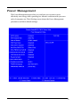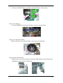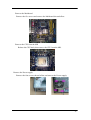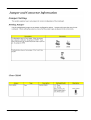
1
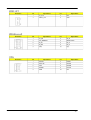
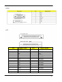
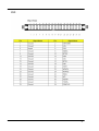
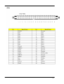
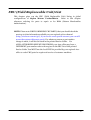
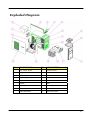
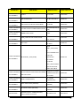
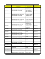
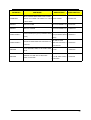
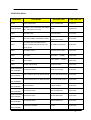
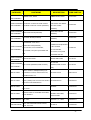
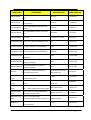
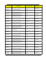
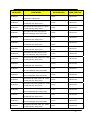
Aspire M1620 VeritonM262 Service Guide Service guide files and updates are available on the AIPG/CSD web;for more information please refer to http:/c/sd.acer.com.tw PRINTED IN TAIWAN Revision History Please refer to the table below for the updates made on Aspire M1620 VeritonM262 service guide. Date Chapter Updates II Copyright Copyright © 2007 by Acer Incorporated. All rights reserved. No part of this publication may be reproduced, transmitted, transcribed, stored in a retrieval system, or translated into any language or computer language, in any form or by any means, electronic, mechanical, magnetic, optical, chemical, manual or otherwise, without the prior written permission of Acer Incorporated. Disclaimer The information in this guide is subject to change without notice. Acer Incorporated makes no representations or warranties, either expressed or implied, with respect to the contents hereof and specifically disclaims any warranties of merchantability or fitness for any particular purpose. Any Acer Incorporated software described in this manual is sold or licensed "as is". Should the programs prove defective following their purchase, the buyer (and not Acer Incorporated, its distributor, or its dealer) assumes the entire cost of all necessary servicing, repair, and any incidental or consequential damages resulting from any defect in the software. Acer is a registered trademark of Acer Corporation. Intel is a registered trademark of Intel Corporation. Pentium 4 and Celeron are trademarks of Intel Corporation. Other brand and product names are trademarks and/or registered trademarks of their respective holders. III Conventions The following conventions are used in this manual: SCREEN Denotes actual messages that appear on screen. MESSAGES NOTE Gives bits and pieces of additional information related to the current topic. WARNING Alerts you to any damage that might result from doing or not doing specific actions. CAUTION Gives precautionary measures to avoid possible hardware or software problems. IMPORTANT Remind you to do specific actions relevant to the accomplishment of procedures. IV Preface Before using this information and the product it supports, please read the following general information. 1. This Service Guide provides you with all technical information relating to the BASIC CONFIGURATION decided for Acer's "global" product offering. To better fit local market requirements and enhance product competitiveness, your regional office MAY have decided to extend the functionality of a machine (e.g. add-on card, modem, or extra memory capability). These LOCALIZED FEATURES will NOT be covered in this generic service guide. In such cases, please contact your regional offices or the responsible personnel/channel to provide you with further technical details. 2. Please note WHEN ORDERING FRU PARTS, that you should check the most up-to-date information available on your regional web or channel. If, for whatever reason, a part number change is made, it will not be noted in the printed Service Guide. For ACER-AUTHORIZED SERVICE PROVIDERS, your Acer office may have a DIFFERENT part number code to those given in the FRU list of this printed Service Guide. You MUST use the list provided by your regional Acer office to order FRU parts for repair and service of customer machines. V Chapter 1 System Specifications 1 Features…………………………………………………………………………... 1 Main board Placement……………………………………………………….10 Block Diagram…………………………………………………………………..11 AspireM1620 Front Panel……………...………….............…………….12 Aspire M1620 Rear Panel……………….………………..............….…..13 VeritonM262 Front Panel………………….................………….….….14 VeritonM262 Rear Panel………………........………...........……………15 Hardware Specifications and Configurations………………….…….16 Power Management Function (ACPI support function)………….22 Chapter 2 System Utilities 23 Entering Setup………………………………………………………………..24 Product Information………………………………………………………..26 Standard CMOS Features…………………………………………………27 Advanced BIOS Features………………………………………………….30 Integrated Peripherals……………………………………………………..34 Power Management…………………………………………………………41 PnP/PCI Configuration…………………………………………………….44 PC Health Status…………………………………………………………......46 Frequency/Voltage Control……………..………………………….…....47 Load Default Settings………………………………………………..……. 49 Set Supervisor/User Password……………………………….…………50 Save & Exit Setup………………………………………………….…………52 Exit Without Saving………………………………………………….……..53 Chapter 3 Machine Disassembly and Replacement 54 General Information………………………………………………………. 55 Disassembly Procedure……………………………………………………56 AspireM1620 Disassembly Procedure…..............……..…………57 VeritonM262 Disassembly procedure………...................………63 Chapter 4 Troubleshooting 73 Chapter 5 Jumper and Connector Information 74 Jumper Setting……………………………………………………………….74 Chapter 6 FRU (Field Replaceable Unit) List 83 Exploded Diagram………………………………………………………….84 Parts……………………………………………………………………………..86 1 System Specifications Features Operating System Microsoft Windows Vista (Home Basic, Home Premium, Business) Processor Socket Type: Intel® Socket T LGA 775 pin Processor Type: Support 105W CPU, Intel® Core 2 Quad, Core 2 Extreme, Core 2 Duo, Pentium® D, Pentium® 4, Celeron D processors , Socket T (LGA775)Intel® Kens field Chipset North Bridge: 945G/GC South Bridge: ICH7 1 PCB Form Factor: ATX Dimension/Layer: 9.6"x 8.8" Memory Memory Type: DDRII 400/533/667 Support single channel 64 bit mode with maximum memory size up to 4GB DIMM Slot: 2 Memory Max: 128Mb/256Mb/512Mb/1Gb devices technologies Capacity: Up to 128MB per DIMM with maximum memory size up to 4 GB Graphics Intel 945G/GC on die graphic solution DVMT 4.0 technology support 2 Enhanced 3D and Clear Video technology support Dual View function support (by Intel ADD2/MEC card) 1 D-sub VGA port on rear PCI PCI Express Slot Type: x16 PCI Express x16 Slot Quantity: 1 Support ADD2/MEC card PCI Express Slot Type: x1 PCI Express x1 Slot Quantity: 1 PCI Slot PCI Slot Quantity: 2 FDD Slot Quantity: 1 Design Criteria: 3 Should support 1.44MB/3 mode 3.5” Devices SATA Slot Type: SATA slot Slot Quantity: 4 Storage Type support: HDD/CD-ROM/CD-RW/DVD-ROM/DVD-RW/DVD+RW/ DVD Dual/DVD SuperMultiPlus/Blu-Ray ODD Audio Audio Type: HD audio codec Audio Channel: 7.1 channel Audio Controller /Codec: ALC883, colay with ALC888 Support S/PDIF: S/PDIF-out header (1*4) 4 LAN MAC Controller: ICH7 Realtek RTL8100C, Colay with 8110SC (10M/100M/1000M LAN) PHY: Intel Nineveh RTL8110SC PCI-E Giga LAN USB Controller Type: Intel ICH7 Ports Quantity: 8 4 back panel ports On-board: 2x5 header x2 Connector Pin: standard Intel FPIO pin definition (2x5) Data transfer rate support: USB 2.0/1.1 5 1394 Controller: Intel ICH7 1 on board header 1 6-pin 1394 port on rear port BIOS BIOS Type: Phoenix Award or AMI Kernel with Acer skin BIOS 4Mb Flash BIOS Note: Boot ROM should be included (PXE function should be built in with default and RPL function is optional by service BIOS) Compliant with latest ASF 2.0 spec Compliant with latest SMT 2.0 spec Compliant with latest Intel Virtualization Technology spec 6 I/O Connector Controller: Super I/O ITE IT8718F with hardware monitor Rear I/O Connector 1 Parallel port, 1 serial port 1 D-Sub VGA port 1 RJ 45 LAN port 4 USB ports 7.1 channel phone jack ( 6 audio jacks) 1 6-pin 1394 port On-board connectors 1 LGA 775 CPU socket 2 DDR2 memory sockets 1 PCI Express x16 slot 7 1 PCI Express x 1 slot 2 PCI slots 1 FDD slot 4 SATA2 connectors 3 2*5 pin Intel FPIO specification USB pin connectors (follow Intel FPIO standard Specification) 1 2*5 pin Intel FPIO spec. Microphone In/ Headphone Out pin connectors 1 serial port 2*5 pin connector (2nd serial port) 1 HD audio digital header 4 pin CPU Fan connector 3 pin System FAN connector with linear circuit 24pin + 4pin ATX interface PS3/PS2 SPS connector 1 2*7 pin front panel IO header 8 1J umper for clear CMOS Color management for on board connecters (please refer to Acer spec) Header for CIR & IR blaster function (Check ITE Solution) Power Supply PSP Type: 250W/300W 9 Main board Placement 10 Block Diagram 11 Aspire M1620 Front Panel The computer’s front panel consists of the following: 12 Aspire M5620 Rear Panel Item Description Item Description 1 6 AUDIO JACKS 8 PS2 KEYBOARD 2 LAN PORT 9 PS2 MOUSE 3 USB PORTS 10 POWER CORD PORT 4 1394 PORT 11 SPDIF BRACKET 5 CRT/LCD PORT 12 SPDIF PORT 6 PARALLEL PORT 13 RECOVERY SWITCH HOLDER 7 COM PORT 14 LOCK HANDLE 13 VeritonM262 Front Panel Label Description 1 Power-Button 2 Speaker-out/Line-out Port 3 Microphone-in out ( Front ) 4 USB Ports 5 Optical drive 8 HDD LED 9 Power LED 14 VeritonM262 Rear Panel Item Description Item Description 1 3 audio jacks 7 PS/2 keyboard 2 RJ45 port 8 PS/2 mouse 3 CRT/LCD port 9 Power cord Port 4 Serial port 10 Recovery Switch Holder 5 Parallel port 11 Lock Handle 6 USB PORTS ʳ ʳ 15 22 System Utilities The manufacturer or the dealer already configures most systems. There is no need to run Setup when starting the computer unless you get a Run Setup message. The Setup program loads configuration values into the battery-backed nonvolatile memory called CMOS RAM. This memory area is not part of the system RAM. NOTE: If you repeatedly receive Run Setup messages, the battery may be bad/flat. In this case, the system cannot retain configuration values in CMOS. Before you run Setup, make sure that you have saved all open files. The system reboots immediately after you exit Setup. 23 Entering Setup Power on the computer and the system will start POST (Power On Self Test) process. When the message of “Press DEL to enter SETUP” appears on the screen, press the key of [Delete] to enter the setup menu. NOTE: If the message disappears before you respond and you still wish to enter Setup, restart the system by turning it OFF and On. You may also restart the system by simultaneously pressing [Ctrl+ Alt+ Delete]. The Setup Utility main menu then appears: 24 The items in the main menu are explained below: Parameter Description Production Information This page shows the relevant information of the main board Standard CMOS Features This setup page includes all the items in standard compatible BIOS Advance BIOS Features This setup page includes all the items of Award special enhanced features Advance Chipset Features This setup page includes all advanced chipset features Integrated Peripherals This setup page includes all onboard peripherals Power Management Setup This setup page includes all the items of Green function features PnP/PCI Configuration This setup page includes all configurations of PCI & PnP ISA resources PC Health Status This setup page is the System auto detect Temperature, voltage, and fan speed Load Optimized Defaults Load Optimized Settings Default Settings indicates the value of the system parameters which the system would be in best performance configuration Set Supervisor Password Change, set or disable password. It allows you to limit access to the system and Setup, or just to Setup Set User Password Change, set or disable password. It allows you to limit access to the System Save & Exit Setup Save CMOS value settings to CMOS and exit setup Exit Without Saving Abandon all CMOS value changes and exit setup 25 Product Information The screen below appears if you select Product Information from the main menu: The Product Information menu contains general data about the system, such as the product name, serial number, BIOS version, etc. This information is necessary for troubleshooting (maybe required when asking for technical support). The following table describes the parameters found in this menu: Parameter Description Production Name This item lists the product name System S/N This item lists the system serial number Main Board ID This item lists the main board ID Main Board S/N This item lists the main board serial number System BIOS Version This item lists the system BIOS version SMBIOS Version This item lists the system SMBIOS version System BIOS ID This item lists the system BIOS ID BIOS Release Date This item lists the BIOS release date 26 Standard CMOS Setup Select standard CMOS features from the main menu to configure some basic parameters in your system the following screen shows the standard CMOS features menu: 27 The following table describes the parameters found in this menu. Parameter Description Options Date To set the date following the weekday-month-date-year format Week: From [Sun.] to [Sat.]. determined by BIOS and is display only Day: from [1] to [31] (or the maximum allowed in the month. Year: from 1999 to 2099 System Time To set the time following the hour-minute-second format The items format is [hour] [minute][second]. The time is calculated base on the 24-hour timer clock. Base Memory Size 640 K for system base memory 28 Parameter Description Extended Memory Size The BIOS determines how much extended memory is present during the POST. This is the amount of memory located above 1MB in the memory address map of CPU Total Memory Size Total memory size for the system IDE Channel X Master IDE Channel X Slave Hard disk drive connected to channel X master or slave port. To enter the IDE Master or Slave setup, press [Enter]. The IDE CD-ROM is always automatically detected Video Setting Select the type of primary video subsystem Halt on This item enables use to select the situation if the BIOS stops the POST process and the notification Options [Enter] for detection options [Auto]: BIOS automatically detects IDE devices during POST (default) [None]: No IDE devices are used and the system will skip the automatic detection step and allow for faster system start up [Manual]: Manually input the correct settings [Access Mode]: To set the access mode for the hard drive. The four options are: CHS/LBA/Large/Auto (default: Auto) Cylinder: Number of cylinders Head: Number of heads Precomp: Write precomp Landing Zone: Landing Zone Sector: Number of sectors All Errors No Errors All, But Keyboard All, But Diskette All, But Disk/Key 29 Advanced Setup The following screen shows the Advanced Setup: The following table describes the parameters found in this menu. Parameter Description Options Hard Disk Boot Priority This features displays the Hard Disk Boot Device priority from high to low and allows users to set the Hard Disk Boot Device Priority. Press [Enter] to enter the setting screen. Use wory to select a device, then press <+> to move it up, or <-> to move it down the list. Press <ESC> to exit. [Press Enter] 30 Parameter Description Options Virus Warning This feature allows you to enable the VIRUS warning function for IDE Hard Disk boot sector protection. If this function is enabled and there is someone attempts to write data to this area, BIOS will show a warning message on screen and the alarm will beep. [Enabled], [Disabled] Quick Power On Self Test This feature allows the system to skip certain tests while booting. When this function is enabled, it will decrease the time needed to boot the system, which means to quick power on self-test function. [Enabled], [Disabled] Silent Boot This feature allows you to enable or disable if the screen logo to display or not during POST [Enabled], [Disabled] First/Second/ Third Boot Device The item allows you to see the sequence of boot device where BIOS attempts to load the disk operation system. [Floppy], [LS120], [Hard Disk], [CD-ROM], [ZIP], [USB-FDD], [USB-ZIP], [USB-CDROM], [USB-HDD], [LAN], [Disabled] Boot From Other Devices This item allows user to enable or disable to boot [Enabled], [Disabled] from other device Boot Up NumLock Status This item allows user to enable or disable to set keyboard is number keys or arrow keys [Enabled], [Disabled] Security Option This category allows you to limit access to the system and Setup, or just to Setup. [System], [Setup] APIC Mode This option is used to set up enable or disable the APCI function [Enabled], [Disabled] HDD S.M.A.R.T Capability S.M.A.R.T. which allows your hard disk to report any read/write errors and issue a warning when LDCM installed [Enabled], [Disabled] 31 Advanced Chipset Setup The following table describes the parameters found in this menu. Parameter Description Options Dual Monitor Support This category allows you to enable or disable dual monitor support function [Enabled], [Disabled] Frame Buffer Size This field displays how much frame buffer size of the system. CPU Frequency This field allows you to determine CPU frequency of the system. 32 Parameter Description Options Spread Spectrum When the system clock generator pulses, the extreme values of the pulse generate excess EMI. Enabling pulse spectrum spread modulation changes the extreme values from spikes to flat curves, thus reducing EMI. This benefit may in some case be outweighed by problems with timing-critical devices, such as a clock-sensitive SCSI device. [Enabled], [Disabled] HT Spread Spectrum Enables or Disables HT Spread Spectrum. HT is Hyper Transport between CPU and North Bridge. [Enabled], [Disabled] SSE/SSE2 Instructions This feature controls the availability of the [Enabled], [Disabled] processor’s SSE and SSE2 instruction sets. When enabled, the processor’s SSE and SSE2 instruction sets are enabled. Software applications can make use of those instructions to better process large amounts of data quickly. When disabled, the processor’s SSE and SSE2 instruction sets are disabled. Software applications will not be able to use those instructions to process multiple data elements simultaneously. However, the processor’s MMX instruction set will still be available for use. It is highly recommended that you leave this BIOS feature at the default setting. 33 Integrated Peripherals The following table describes the parameters found in this menu. Parameter Description Options IDE Function Setup This page allows you to setup IDE function [Press Enter] Onboard Device Setup This page allows you to setup onboard devices. [Press Enter] Onboard I/O Chip Setup This page allows you to setup onboard I/O chip. [Press Enter] 34 Integrated Peripherals-IDE Function Setup 35 The following table describes the parameters found in this menu. Parameter Description IDE Primary/Second ary Master/Slave PIO The four IDE PIO fields let you set a PIO mode (0-4) for each of the four IDE devices that the onboard IDE interface supports. Modes 0 through 4 provide increased performance. In Auto mode, the system automatically determines the best mode for each device. On-Chip IDE First/Second Channel The Chipset contains a PCI IDE interface with support for two IDE channels. Select Enabled to activate the first and/or second IDE interface. Select Disabled to deactivate an interface, if you install a primary and/or secondary add-in IDE interface. IDE Primary/Second ary Master/Slave UDMA UDMA (Ultra DMA) is a DMA data transfer protocol that utilized ATA transfer protocol that utilizes ATA commands and the ATA bus to allow DMA commands to transfer data ata maximum burst rate of 33 MB/s. When you select Auto in the four IDE UDMA fields (for each of up to four IDE devices that the internal PCI IDE interface supports), the system automatically determines the optimal data transfer rate for each IDE device. IDE DMA Transfer Access This category allows you to enable or disable DMA transfer access of IDE device (or IDE HDD) SATA 1/2 Enable/Disable Serial-ATA 1 or Serial-ATA-2. SATA 1 control port 1 and 3, SATA 2 control port 2 and 4. IDE Prefetch Mode The onboard IDE drive interfaces supports IDE prefetching, for faster drive accesses. If you install a primary and/or secondary add-in IDE interface, set this field to Disabled if the interface does not support prefetching. Options [Enabled], [Disabled] [Enabled], [Disabled] 36 Parameter Description Options IDE HDD Block Mode Block mode is also called block transfer, multiple commands, or multiple sectors read/write. If your IDE hard drive supports block mode(most new drives do), select Enabled for automatic detection of the optimal number of block read/write per sector the drive can support. [Enabled], [Disabled] SATA PORT Speed Settings This category allows you to determine the speed of SATA port. [Auto], Integrated Peripherals-Onboard Device Setup 37 The following table describes the parameters found in this menu. Parameter Description Options On Chip USB This field allows you to determine on chip USB type or disable on chip USB. [V1.1+V2.0], [V1.1] UDB Memory Type Use this item to change the type of USB memory to shadow or Base memory. [Shadow], [Base Memory] USB KB Legacy Support This field enables or disables USB keyboard support function. [Enabled], [Disabled] USB Mouse Support This field enables or disables USB mouse support function. [Enabled], [Disabled] AC 97 Audio Change the on board Audio to auto or disabled [Auto], [Disable] MAC LAN Enables or disables onboard LAN [Enabled], [Disabled] controller, If you wish to use the motherboard’s onboard LAN controller, you should certainly enable this BIOS feature. You can disable this feature if you do not want to use the motherboard’s onboard LAN controller. This may free up an IRQ for other devices to use. This is useful if your motherboard does not support APIC and have many devices that can not share IR Qs. MAC LAN Boot ROM Enables or disables on board LAN boot ROM. [Enabled], [Disabled] 38 Integrated Peripherals -Onboard I/O Chip Setup 39 The following table describes the parameters found in this menu. Parameter Description Options Onboard FDC Controller Select Enabled if your system has a floppy disk controller (FDC) installed on the system board and you wish to use it. If you install an add-in FDC or the system has no floppy drive, select Disabled in this field. [Enabled]. [Disabled] Onboard Serial Port 1 Select a logical COM port name and matching address for the serial port. Select an address and corresponding interrupt for the serial port. UR2 Duplex Mode In an infrared port mode, this field appears. Full-duplex mode permits simultaneous tow-direction transmission. Half-duplex mode permits transmission in one direction only at a time. Select the value required by the IR device connected to the IR port. Onboard Parallel Port Select a logical LPI port address and corresponding interrupt for the physical parallel port. [xxx+IRQx] Parallel Port Mode Select an operating mode for the onboard parallel (printer) port. [Normal], [EPP], [EPP], [EPP+ECP] ECP Mode used DMA This item allows users to manually set the DMA channel for ECP mode 40 Power Management The Power Management menu lets you configure your system to most effectively save energy while operating in a manner consistent with your own style of computer use. The following screen shows the Power Management parameters and their default settings: 41 The following table describes the parameters found in this menu. Parameter Description Options ACPI Function This item allows you to enable or disable the ACPI function [Enabled], [Disabled] ACPI Suspend Type This item specifies the power saving modes for ACPI function. S1 (POSP: The S1 sleep mode is a low power state.. In this state, no system context (SPU or chipset) is lost and hardware maintains all system context/ S3 (STR): The S3 sleep mode is s power-down state in which power is supplied only to essential components such as main memory and wake-capable devices and all system context is saved to main memory. The information stored in memory will be used to restore the PC to the previous state when an wake-up event occurs. [S1 (POS)]: Set ACPI suspend type to S1/POS (Power On Suspend). [S3 (STR)]: Set ACPI suspend type to S3/STR HDD Power Down The setting controls how long a hard disk drive must be left idle before it spins downs. [Disabled], [Standby], [Suspend] HDD Down In Suspend Enables or Disables the functionality of HDD down in suspend [Enabled], [Disabled] 42 Parameter Description Options Soft-off by PWR/BTTN When Enabled, turning the system off with the on/off button places the system in a very low-power-usage state, with only enough circuitry receiving power to detect power button activity or Resume by Ring activity. [Instant-off]: Press down button then power off instantly [Delay 4 Sec.]: Press Power button 3 sec. to power off. Enter suspend if button is pressed less than 4 sec. WOL (PME#) From Soft-Off This category enables or disables wake-on-Lan from soft-off [Enabled], [Disabled] Resume by Alarm You can set “Resume by Alarm” item to enabled and key in Date/Time to power on system. [Disabled] [Enabled]: Enable alarm function to Power On system. If RTC Alarm Lead to Power On is Enabled, Date( of Month) Alarm: Everyday, 1~31 Time(hh:mm:ss) Alarm: (0.~23):(0-59):(0~59) POWER ON Function Select the method to power on the system [Button Only], [Keyboard 98], [Hot Key], [Mouse Left], [Mouse Right] POWER After PWR-Fail This field allows you to determine the power status to on/off or former-sts after the system [FORMER-Sts], [On], [Off] 43 PCI/PnP Setup 44 The following table describes the parameters found in this menu. Parameter Description Options Init Display First Initialize the AGP video display before initializing any other display device on the system. Thus the AGP display becomes the primary display. Reset Configuration Data Normally, you leave this field Disabled. Select Enabled to reset Extended System Configuration Data (ESCD) when you exit Setup if you have installed a new add-on and the system reconfiguration has caused such a serious conflict that the operating system cannot boot [Enabled], [Disabled] Resources Controlled By This item allows user to assign PnP resource (I/O address, IRQ&DMA channels) for Plug and Play compatible devices automatically or manually [Auto] [Manual] IRQ Resources When resource are controlled by manually, assign [Press Enter] each system interrupt a type , depending on the type of device using the interrupt. Option: [PCI Device]: Assign this IRQ for PCI device. [Reserved]: Reserve this IRQ for other device. PCI/VGA Palette Snoop This option is only very rarely needed. It should be left at “Disabled” unless a video device specifically requires the setting enabled upon installation. [Disabled], [Enabled] Maximum Payload Size This field displays maximum payload size of the system [128-4096] PCI 1/2 IRQ Assignment This item allows user to assign PCI IRQ for device [Auto], [3] , [4] , [5] , [6] , [7], [10] , [11] , [12] , [14] , [15] 45 PC Health Status 46 The following table describes the parameters found in this menu: Parameter Description V core Detect system’s voltage status automatically CPU Temperature Detect CPU Temperature automatically CPU/SYSTEM FAN Speed (RPM) Detect CPU/SYSTEM Fan Speed Status automatically CPU Smart FAN Control The item displays the system Smart Fan Function status. It is always enabled by system. Options Frequency/Voltage Control CMOS Setup Utility - Copyright (C) 1985-2005,American Megatrends,Inc. Frequency/Voltage Control Manufacturer: Intel Help Item Ratio Status: Unlocked (Min:06,Max:10) Ratio Actual Value: 10 Options CPU Frequency : 266MHz Auto Detect DIMM/PCI CLK Enabled Disabled Spread Spectrum Enabled Enabled KLIJ :Move Enter: Select +/-/:Value F10:Save ESC:Exit F1:General Help F9:Optimized Defauits 47 The following table describes the parameters found in this menu: Parameter Description Optio ns Auto Detect DIMM/PCI CLK This option allows you to enable/disable the feature of auto detecting the clock frequency of the installed PCI bus. Enabled Disabled Manufacturer This item specifies CPU Manufacturer Intel CPU frequency This item specifies CPU frequency 266MHz Spread Spectrum When the motherboard’s clock generator pulses, the extreme values (spikes) of the pulses create EMI (Electromagnetic Interference). The spread Spectrum function reduces the EMI generated by modulating the pulses so that the spikes of the pulses are reduced to flatter curves. If you do not have any EMI problem, leave the setting at Disabled for optimal system stability and performance. But if you are plagued by EMI, setting to Enabled for EMI reduction. Remember to disable Spread Spectrum if you are overlooking because even a slight jitter can introduce a temporary boost in clock speed which may just cause your over lock ed processor to lock up. Enabled 48 Load Default Settings This option opens a dialog box that lets you install defaults for all appropriate items in the Setup Utility. Parameter Description Load Default Settings Select the field loads the factory defaults for BIOS and Chipset Features, which the system automatically detects. This option opens a dialog box that lets you install optimized defaults for all appropriate items in the Setup Utility. Options 49 Set Supervisor/User Password When this function is selected, the following message appears at the center of the screen to assist you in creating a password. 50 Parameter Description Options Set When this function is selected, the following message Supervisor/User appears at the center of the screen to assist you in Password creating a password. ENTER PASSWORD Type the password, up to eight characters, and press<Enter>. The password typed now will clear any previously entered password from CMOS Memory. You will be asked to confirm the password. Type the password again and press <Enter>. You may also press<ESC> to abort the selection. PASSWORD DISABLED To disable password, just press<Enter> when you are prompted to enter password with empty. A message will confirm the password being disabled. If you have selected “System” in “Security Option” of “BIOS Feature Setup” menu, you will be prompted for the password every time the system reboots or any time you try to enter BIOS Setup. If you have selected “Setup” at “Security Option” from “BIOS Features Setup” menu, you will be prompted for the password only when you enter BIOS Setup. Supervisor Password has higher priority than User Password. You can use Supervisor Password when booting the system or entering BIOS Setup to modify all settings. 51 Save & Exit Setup Highlight this item and press <Enter> to save the changes that you have made in the Setup Utility and exit the Setup Utility. Parameter Description Options Save & Exit Setup Press <Enter> to save the changes that have made in the Setup Utility and exit the Setup Utility. Press<Y> to save and Exit or <N> to return to the main menu. 52 Exit Without Saving Highlight this item and press <Enter> to discard any changes that you have made in the Setup Utility and exit the Setup Utility. Parameter Description Exit Without Saving Press<Enter> to discard any changes and exit the Setup Utility Options 53 Machine Disassembly and Replacement To disassemble the computer, you need the following tools: Wrist grounding strap and conductive mat for preventing electrostatic discharge. Wire cutter. Phillips screwdriver (may require different size). NOTE: The screws for the different components vary in size. During the disassembly process, group the screws with the corresponding components to avoid mismatches when putting back the components. 54 General Information Before You Begin Before proceeding with the disassembly procedure, make sure that you do the following: 1. Turn off the power to the system and all peripherals. 2. 2.Unplug the AC adapter and all power and signal cables from the system 55 Disassembly Procedure This section tells you how to disassemble the system when you need to perform system service. Please also refer to the disassembly video, if available. CAUTION: Before you proceed, make sure you have turned off the system and all peripherals connected to it. 56 Aspire M1620 Standard Disassembly Process Opening the System 1. Place the system unit on a flat, steady surface. 2. Turn the housing down, slide the Lock-handle as shown , meanwhile slide the left side door out . Remove the ADD ON Cards 1. Release the PCI-Lock as shown bellow, then remove it. 2. Release the VGA-slot Lock shown bellow, then pull out the VGA Card. 57 3. Remove the Modem card. Remove the Cables 1. Disconnect the AUDIO cable from the MB “AUDIO”. 2. Disconnect the USB and Card-reader cables from the MB connecter “F_USB1, F_USB2”. USB CABLE 2 USB CABLE 1 58 3. Disconnect the LED cable ASSY from the MB Connector “F_PANEL”. 4. Disconnect the 12V power cable “PD” from the MB Connector. 5. Disconnect the CPU fan power cable from the MB Connector “CPU_FAN”. 6. Disconnect the 4 Pin power cable “PE” from the ODD. 7. Disconnect the ODD IDE cable from the ODD. 59 7-1. Disconnect the FDD IDE cable from the FDD. 8. Disconnect the FDD power cable from the FDD. 9. Disconnect the power cable from the HDD. 10. Disconnect the HDD DATA cable from the HDD. 60 11. Disconnect the P1 power cable from the MB connector. 12. Disconnect the FDD IDE cable from the MB connector. 13. Disconnect the ODD IDE cable from the MB connector. 14. Disconnect the HDD DATA cable from the MB connector. Remove the front bezel Release the three latches on the front bezel, then remove the front bezel. 61 Remove the CD-ROM, Floppy, Card-reader and HDD 1. Release the ODD-Holder, meanwhile pull the ODD out of the chassis. 2. Release the FDD-Holder1, meanwhile pull the FDD out of the chassis. 3. Release the FDD-Holder2, meanwhile pull the Card-reader Module out of the chassis. 62 4. Release the HDD-Holder, meanwhile pull the HDD out of the chassis. Remove the Memory Loose the DIMM Latch and pop out the two memory shown bellow. Remove the Heatsink module. Remove the four screws shown bellow , then remove the Heatsink. Removing the USB Module Remove the screw as shown bellow, detach the USB Module, then pull down the USB&Audio cable from the USB board. 63 Remove the Mainboard Remove the five screws and remove the Mainboard shown bellow. Remove the CPU from the MB Release the CPU latch, then remove the CPU from the MB. Remove the Power-supply Remove the four screws shown bellow and remove the Power-supply. 64 VeritonM262 Standard Disassembly Process Opening the System 3. Place the system unit on a flat, steady surface. 4. Turn the housing down, slide the Lock-handle as shown , meanwhile slide the left side door out . Remove the ADD ON Cards 4. Release the PCI-Lock as shown bellow, then remove it. 5. Release the VGA-slot Lock shown bellow, then pull out the VGA Card. 65 6. Remove the Modem card. Remove the Cables 15. Disconnect the AUDIO cable from the MB “AUDIO”. 16. Disconnect the USB and Card-reader cables from the MB connecter “F_USB1, F_USB2”. USB CABLE 2 USB CABLE 1 66 17. Disconnect the LED cable ASSY from the MB Connector “F_PANEL”. 18. Disconnect the 12V power cable “PD” from the MB Connector. 19. Disconnect the CPU fan power cable from the MB Connector “CPU_FAN”. 20. Disconnect the 4 Pin power cable “PE” from the ODD. 21. Disconnect the ODD IDE cable from the ODD. 67 7-1. Disconnect the FDD IDE cable from the FDD. 22. Disconnect the FDD power cable from the FDD. 23. Disconnect the power cable from the HDD. 24. Disconnect the HDD DATA cable from the HDD. 68 25. Disconnect the P1 power cable from the MB connector. 26. Disconnect the FDD IDE cable from the MB connector. 27. Disconnect the ODD IDE cable from the MB connector. 28. Disconnect the HDD DATA cable from the MB connector. Remove the front bezel Release the three latches on the front bezel, then remove the front bezel. 69 Remove the CD-ROM, Floppy, Card-reader and HDD 5. Release the ODD-Holder, meanwhile pull the ODD out of the chassis. 6. Release the FDD-Holder1, meanwhile pull the FDD out of the chassis. 7. Release the FDD-Holder2, meanwhile pull the Card-reader Module out of the chassis. 70 8. Release the HDD-Holder, meanwhile pull the HDD out of the chassis. Remove the Memory Loose the DIMM Latch and pop out the two memory shown bellow. Remove the Heatsink module. Remove the four screws shown bellow , then remove the Heatsink. Removing the USB Module Remove the screw as shown bellow, detach the USB Module, then pull down the USB&Audio cable from the USB board. 71 Remove the Mainboard Remove the five screws and remove the Mainboard shown bellow. Remove the CPU from the MB Release the CPU latch, then remove the CPU from the MB. Remove the Power-supply Remove the four screws shown bellow and remove the Power-supply. 72 Troubleshooting Please refer to generic troubleshooting guide for troubleshooting information relating to following topics: Power-On Self-Test (POST) POST Check Points POST Error Messages List Error Symptoms List 73 74 75 ATX_POWER: ATX 24-pin Power Connector 1 2 3 4 5 6 7 8 9 10 11 12 13 14 15 16 17 18 19 20 21 22 23 24 Pin Signal Name Pin Signal Name 1 +3.3 13 +3.3V 2 +3.3 14 -12V 3 COM 15 COM 4 +5V 16 PS_ON 5 COM 17 COM 6 +5V 18 COM 7 COM 19 COM 8 PWR OK 20 -5V 9 5VSB 21 +5V 10 +12V 22 +5V 11 +12V 23 +5V 12 +3.3V 24 COM 76 77 78 79 Pin Signal Name Pin Signal Name 1 STROBE 14 ALF 2 PD0 15 ERROR 3 PD1 16 INIT 4 PD2 17 SLCTIN 5 PD3 18 GROUND 6 PD4 19 GROUND 7 PD5 20 GROUND 8 PD6 21 GROUND 9 PD7 22 GROUND 10 ACK 23 GROUND 11 BUSY 24 GROUND 12 PE 25 GROUND 13 SLCT 80 81 82 FRU (Field Replaceable Unit) List This chapter gives you the FRU (Field Replaceable Unit) listing in global configurations of Aspire M1620 VeritonM262. Refer to this chapter whenever ordering for parts to repair or for RMA (Return Merchandise Authorization). NOTE: Please note WHEN ORDERING FRU PARTS, that you should check the most up-to-date information available on your regional web or channel (http://aicsl.acer.com.tw/spl/, if you do not own a specific account, you can still access the system with guest; guest). For whatever reasons a part number change is made, it will not be noted in the printed Service Guide. For ACER-AUTHORIZED SERVICE PROVIDERS, your Acer office may have a DIFFERENT part number code to those given in the FRU list of this printed Service Guide. You MUST use the local FRU list provided by your regional Acer office to order FRU parts for repair and service of customer machines. 83 Exploded Diagram NO DESCRIPTION NO DESCRIPTION 1 AM30_MAIN_BEZEL 10 POWER SUPPLY 2 AM50_USB 11 FAN 3 AM50_USB_PANEL 12 PCI-BRACKET 4 FDD_LOCK_SLIDE 13 LEFT SIDE DOOR 5 CD_ROM LOCK SLIDE 14 HOTHER BOARD 6 CHASSIS 15 HDD 7 USB_PCB_ASN 16 3.5 DEVICE 8 USB-SHIELDING 17 CD-ROM 9 RIGHT SIDE DOCR 18 HDD-LOCK-SLIDE 84 NO DESCRIPTION NO DESCRIPTION 1 TOP-SHOELD 8 CDROM-LOCK-SLIDE 2 3.25 ROTATE COVER 9 RIGHT-SIDE 3 CD-ROM 10 USB MODULE 4 FDD 11 CHASSIS 5 HDD 12 POWER-SUPPLY 6 HDD-LOCK-SLIDE 13 LEFT-SCDE 7 FDD-LOCK-SLIDE 14 MAINBOARD 85 PARTS ASPIRE M1620 CATEGORY PARTNAME DESCRIPTION ACER PART NO. BOARD POWER SWITCH DB, ROHS POWER SWITCH DB 55.P22VF.002 BOARD USB BOARD USB BOARD 55.S950A.001 NEW CR126 CR.10400.002 3.5 USB1.1 9-IN-1 CARD READER, WITH CARD READERS USB CABLE , WITH IMPROVED USB CONNECTOR,SUPPORT USB2.0 FRONT PANEL CABLE. CABLE FRONT PANEL CABLE. 4PINS 50.S950A.004 4PINS IDE CD-ROM CABLE CABLE IDE CD-ROM CABLE ATA66 40PIN 50.S46VF.008 ATA66 40PIN CABLE HDD CABLE SATA_1 HDD CABLE SATA_1 50.S46VF.001 CABLE SATA ODD CABLE SATA ODD CABLE 50.P37VF.002 CABLE SATA ODD CABLE SATA ODD CABLE 50.P40VF.003 CABLE USB CABLE USB CABLE 50.S46VF.002 CABLE AUDIO CABLE AUDIO CABLE 50.S46VF.004 CABLE IDE FDD CABLE 34PIN IDE FDD CABLE 34PIN 50.S46VF.007 COVER SLOT, ROHS COVER SLOT CASE/COVER/BRAC 33.P22VF.001 KET ASSEMBLY CASE/COVER/BRAC S-LOCK-HANDLE S-LOCK-HANDLE KET ASSEMBLY 42.S46VF.004 H401/H701 ABS CASE/COVER/BRAC ODD HOLDER ASSY ODD HOLDER ASSY 42.S46VF.005 FDD HOLDER ASSY FDD HOLDER ASSY 42.S46VF.006 HDD HOLDER ASSY HDD HOLDER ASSY 42.S46VF.007 KET ASSEMBLY CASE/COVER/BRAC KET ASSEMBLY CASE/COVER/BRAC KET ASSEMBLY 86 CATEGORY PARTNAME DESCRIPTION ACER PART NO. CASE/COVER/BRAC PCI-BKT DF2 PCI-BKT 42.S46VF.008 USB HOLDER ASSY USB BKT FOR AM10 42.S890F.001 FDD COVER FOR AM100 300 500 BEZEL 3-5-COVER 42.S950A.002 KET ASSEMBLY CASE/COVER/BRAC KET ASSEMBLY CASE/COVER/BRAC KET ASSEMBLY CASE/COVER/BRAC 5-25-COVER(BLANK,B 5-25 ODD COVER OF AM300 BEZEL,BLACK KET ASSEMBLY 42.S950A.003 LACK) CASE/COVER/BRAC RUBBER FOOT, ROHS FOOT 47.P22VF.002 KET ASSEMBLY CASE/COVER/BRAC LOGO ACER ACER_LOGO1 IN TOP-COVER, ROHS KET ASSEMBLY 47.P35VF.001 55.12*13.4*0.5 CASE/COVER/BRAC PLASTIC TOP-LOGO TOP-LOGO KET ASSEMBLY 47.S890F.001 FOR AM10 AM100 BEZEL_ASSY(2USB) W/I AM10-POWER-BUTTO N LAN-LED CASE/COVER/BRAC AM100 BEZEL_ASSY(2USB) LED-HOLDER 60.S890F.002 KET ASSEMBLY 5-25-COVER 3-5-COVER ACER_LOGO POWER SWITCH DB FRONT PANEL LED CABLE H402 BASIC CHASISS CASE/COVER/BRAC H402 CHASISS W/ SIDE DOORS W/O BEZEL W/ SIDE DOORS,W/O 60.S950A.001 KET ASSEMBLY AND TOP-COVER TOP COVER CASE/COVER/BRAC TOP-COVER UPPER CASE(PAINTED) KET ASSEMBLY 60.S950A.002 (PAINTED,IRON) CASE/COVER/BRAC RIGHT-SIDE COVER RIGHT-SIDE COVER (PAINTED) KET ASSEMBLY 60.S950A.003 (PAINTED) CASE/COVER/BRAC LEFT-SIDE COVER LEFT-SIDE COVER (PAINTED) KET ASSEMBLY 60.S950A.004 (PAINTED) RADEON 2400PRO 128MB(ONBOARD) ADD-ON CARD 188-01E40-011AC VG.APC24.P01 HYNIX HY5PS56121A FP-25, 87 CATEGORY PARTNAME DESCRIPTION ACER PART NO. PRONET PCI MODEM CARD HPI56M3F ADD-ON CARD HPI56M3 FX.56M03.003 W/ATX BKT, ROHS CPU/PROCESSOR CELERON D 430 CD430 KC.D0001.430 CPU/PROCESSOR CORE 2 DUO E4500 (2.2G 2M 800FSB) C2DE4500 KC.45001.DE0 CPU/PROCESSOR CORE 2 DUO E4400 (2.0G 2M 800FSB) C2DE4400 KC.44001.DE0 PDCE2160 KC.21601.DEP PDCE2140 KC.21401.DEP PDCE2180 KC.21801.DEP PENTIUM DUAL CORE E2160 (1.8G 1M CPU/PROCESSOR 800FSB) PENTIUM DUAL CORE E2140 (1.6G 1M CPU/PROCESSOR 800FSB) CPU INTEL PENTIUM DUAL-CORE E2180 CPU/PROCESSOR PGA 2.0G 1M 800 775 65W PKP367G01U12 + FOXCONN CPU COOLER PKP367G01U12 + FAN SINK SUNON 9225 4200RPM HI.3670C.001 SUNON 9225 4200RPM FAN FAN DVD-RW DRIVE DH-A1S16 LF BLACK BEZEL HA11 SATA DH-A1S1 KU.01609.004 GSA-H40N , LF , DVD-RW DRIVE KU.0160D.029 16X , PATA DASP , SIP 5.0 HLDS SATA DVD-DUAL GSA-H31N LF , SATA , SIP 5.0 , NEW BEZEL , F/W: 1.01, FOR DVD DUAL DRIVE KU.0160D.025 VISTA GSA-H31N SONY FDD 1.44M 3.5(BLACK) , ROHS MPF920 FDD/FLOPPY DISK PZ.12700.008 DRIVE HDD/HARD DISK PATHFINDER II, 80G SATA3.0GBPS 8MB 7200 NCQ, DRIVE KH.08007.024 HDS721680PLA380 HDD/HARD DISK PATHFINDER II, 160G SATA3.0GBPS 8MB 7200 NCQ, DRIVE KH.16007.015 HDS721616PLA380 HDD/HARD DISK VANCOUVER V, 250G SATA3.0GBPS 8MB 7200 NCQ, DRIVE KH.25007.010 HDT25025VLA380 USB KEYBOARD USB KEYBOARD KU-0355 US VER. KU-0355 US VER. 104KS(WITH EKEY VISTA) ROHS 104KS(WITH EKEY KEYBOARD KB.KUS03.222 VISTA) ROHS 88 CATEGORY PARTNAME DESCRIPTION ACER PART NO. USB KEYBOARD USB KEYBOARD KU-0355 T.CHINESE VER. KU-0355 T.CHINESE KEYBOARD KB.KUS03.223 104KS(WITH EKEY VISTA) ROHS VER. 104KS(WITH EKEY VISTA) ROHS USB KEYBOARD USB KEYBOARD KU-0355 IN'L US VER. KU-0355 IN'L US VER. 104KS(WITH EKEY VISTA) ROHS 104KS(WITH EKEY KEYBOARD KB.KUS03.225 VISTA) ROHS USB KEYBOARD USB KEYBOARD KU-0355 ARABIC VER. KU-0355 ARABIC VER. 104KS(WITH EKEY VISTA) ROHS 104KS(WITH EKEY KEYBOARD KB.KUS03.226 VISTA) ROHS USB KEYBOARD USB KEYBOARD KU-0355 THAI VER. KU-0355 THAI VER. 104KS(WITH EKEY VISTA) ROHS 104KS(WITH EKEY KEYBOARD KB.KUS03.227 VISTA) ROHS USB KEYBOARD SK-9610 US VER. KEYBOARD SK-9610 KB.USB0B.006 SK-9610 KB.USB0B.007 SK-9610 KB.USB0B.008 SK-9610 KB.USB0B.009 SK-9610 KB.USB0B.010 SK-9610 KB.USB0B.011 104KS(WITH EKEY VISTA) ROHS USB KEYBOARD SK-9610 T.CHINESE VER. KEYBOARD 104KS(WITH EKEY VISTA) ROHS USB KEYBOARD SK-9610 S.CHINESE KEYBOARD 104KS(WITH EKEY VISTA) ROHS USB KEYBOARD SK-9610 IN'L US VER. KEYBOARD 104KS(WITH EKEY VISTA) ROHS USB KEYBOARD SK-9610 ARABIC VER. KEYBOARD 104KS(WITH EKEY VISTA) ROHS USB KEYBOARD SK-9610 THAI VER. KEYBOARD 104KS(WITH EKEY VISTA) ROHS PS/2 BALL MOUSE, 2 BUTTON+WHEEL, NETSCROLL LEAD-FREE PS2(BLACK) POINTING DEVICE MS.NET04.002 USB OPTICAL MOUSE, MUV ACR1, (ROHS), M-UV ACR1 (BLACK), POINTING DEVICE POINTING DEVICE MS.MUV01.005 W/ STK LABEL (ROHS) PS/2 OPTICAL MOUSE, SBF96, ROHS SBF96 (BLACK) MS.PS201.002 USB OPTICAL MOUSE, POINTING DEVICE MS.N1204.001 USB OPTICAL MOUSE, N12ROU, ROHS N12ROU, ROHS 89 CATEGORY PARTNAME DESCRIPTION ACER PART NO. MB KIT F945GC INTEL945GC+ICH7 / INTEL MAINBOARD LGA775 CPU / DDRII / HD CODEC / LF / RM / MB KIT F945GC MB.SAA09.002 IO SHIELDING MEMORY DDRII 667 512MB NT512T64U88B0BY-3C KN.51203.034 MEMORY DDRII 667 1024MB NT1GT64U8HB0BY-3C KN.1GB03.017 FSP ATX-250PA(1PF) FSP ATX-250PA(1PF) (PFC) POWER SUPPLY POWER SUPPLY (PFC) POWER SUPPLY PY.25008.019 (250W) (250W) PSU DELTA 250W PSU DELTA 250W NONE PFC PS2 SATA X 4 POWER SUPPLY NONE PFC PS2 SATA PY.25009.006 & PATA X 1 X 4 & PATA X 1 JS 2.0 SPEAKER,USB,M-1118C ACER LOGO SPEAKER M-118C SP.10600.008 ROHS SPEAKER 2.0 USB JS SPEAKER 2.0 USB JS M-1118B, ACER SPEAKER M-1118B, ACER LOGO, SP.11805.003 LOGO, LEAD-FREE LEAD-FREE 90 VERITON M262 CATEGORY BOARD PARTNAME FRONT USB BOARD DESCRIPTION ACER PART NO. FRONT USB BOARD 55.S650F.001 CR126 CR.10400.002 SATA ODD Cable 50.P37VF.001 3.5" USB1.1 9-in-1 card reader, with USB2.0 CARD READERS cable , with USB 2.0 connector CABLE SATA ODD Cable CABLE SATA ODD POWER CONVERTOR CABLE SATA ODD POWER 50.P37VF.002 CONVERTOR CABLE LED CABLE ASSY (POWER SWITCH CABLE CABLE, POWER LED CABLE, HDD LED LED CABLE ASSY,ROHS 50.S34VF.007 CABLE),ROHS CABLE HDD CABLE SATA_1 SATA-HDD DATA CABLE 50.S46VF.001 CABLE USB CABLE USB CABLE (460MM ) 50.S46VF.002 CABLE AUDIO CABLE AUDIO CABLE (560MM ) 50.S46VF.004 CABLE IDE FDD CABLE 34PIN FDD DATA CABLE 50.S46VF.007 I/O BRACKET, ROHS COVER SLOT, ROHS 33.P22VF.001 CASE/COVER/BRA CKET ASSEMBLY CASE/COVER/BRA EMPTY COVER FOR 5.25" DEVICE,ROHS 5.25" FILLER PANEL,ROHS 42.S34VF.002 CKET ASSEMBLY CASE/COVER/BRA FILLER COVER FOR 3 1/2" DEVICE,ROHS 3.5" FILLER PANEL,ROHS 42.S34VF.003 CKET ASSEMBLY CASE/COVER/BRA S-LOCK-HANDLE S-LOCK-HANDLE 42.S46VF.004 ODD HOLDER ASSY ODD HOLDER ASSY 42.S46VF.005 FDD HOLDER ASSY FDD HOLDER ASSY 42.S46VF.006 HDD HOLDER ASSY HDD HOLDER ASSY 42.S46VF.007 IO BRACKET HOLDER PCI-BKT 42.S46VF.008 CKET ASSEMBLY CASE/COVER/BRA CKET ASSEMBLY CASE/COVER/BRA CKET ASSEMBLY CASE/COVER/BRA CKET ASSEMBLY CASE/COVER/BRA CKET ASSEMBLY 91 CATEGORY PARTNAME DESCRIPTION ACER PART NO. CASE/COVER/BRA RUBBER FOOT, ROHS RUBBER FOOT, ROHS 47.P22VF.002 CKET ASSEMBLY H402 BASIC CHASISS W/ CASE/COVER/BRA H402 BASIC CHASISS W/ SIDE DOORS SIDE DOORS W/O BEZEL 60.S950A.001 CKET ASSEMBLY W/O BEZEL AND TOP-COVER (PAINTED) AND TOP-COVER (PAINTED) CASE/COVER/BRA RIGHT-SIDE COVER RIGHT-SIDE DOOR (PAINTED) CKET ASSEMBLY 60.S950A.003 (PAINTED) CASE/COVER/BRA LEFT-SIDE COVER LEFT-SIDE DOOR (PAINTED) CKET ASSEMBLY 60.S950A.004 (PAINTED) VM200 BEZEL ASSY WITH VM200 BEZEL ASSY WITH POWER-BUTTON(PAINTED POWER-BUTTON(PAINTED), CASE/COVER/BRA ), LED-HOLDER, LED-HOLDER, 5.25-COVER ABS, CKET ASSEMBLY 60.V580F.001 5.25-COVER ABS, 3.5'-COVER, Front panel power/HDD LED 3.5'-COVER, Front panel cabl power/HDD LED cabl CASE/COVER/BRA USB HOLDER 2USB USB HOLDER 2USB 33.S710F.001 CKET ASSEMLY TOP COVER CASE/COVER/BRA TOP COVER (PAINTED,SAME AS H401) (PAINTED,SAME AS H401 60.S710F.001 CKET ASSEMLY &402) Radeon 2400Pro 128MB(onboard) Hynix ADD-ON CARD HY5PS56121A FP-25, 188-01E40-011AC, 188-01E40-011AC VG.APC24.P01 DDR2 (128bits) VGA+TVO+DVI PAL W/ATX 188-06N02-00AAC VG.PC86G.S11 D-SUB/DVI/Video out PC PARTNER GEFORCE 8600GS 512MB ADD-ON CARD BKT ROHS 188-06N02-00AAC Pronet PCI Modem Card HPI56M3F w/ATX ADD-ON CARD HPI56M3F FX.56M03.003 BKT, RoHS MODEM CARD PCI MODEM CARD PCI HPI56MIII W/ATX BKT, ADD-ON CARD HPI56MIII W/ATX BKT, FX.56M03.001 ROHS PRONET ROHS PRONET COMBO MODULE 52X, SATA DH-52C1S , LF , SATA KO.05209.014 DH-16W1S KU.01609.002 Liteon 16X SATA DVD-Dual DH-16W1S, DVD DUAL DRIVE RoHS, F/W: 2A11 92 CATEGORY PARTNAME DESCRIPTION ACER PART NO. 16X SuperMulti Model:DH-16A1P,RoHS F/W DVD RW DRIVE DH-16A1P KU.01609.003 DH-16A1S KU.01609.004 DH-52C2S KO.05209.015 RA11 Lite-On SuperMulti Model:DH-16A1S SATA DVD RW DRIVE ROHS FW:HA11 Lite-On Combo Model:DH-52C2S SATA DVD-ROM DRIVE FW:NA12 Liteon DVD-ROM DH-16D1P, RoHS, F/W: DVD-ROM DRIVE DH-16D1P KV.01609.001 FA11 DVD-ROM DRIVE 16X, SATA DH-16D1S , LF , SATA KV.01609.002 CPU/PROCESSOR Celeron 430 (1.8G 512K 800FSB LGA775) 430 KC.D0001.430 CPU/PROCESSOR Core 2 Duo E4500(2.2G 2M 800FSB)L2 E4500 KC.45001.DE0 CPU/PROCESSOR Core 2 Duo E4400(2.0G 2M 800FSB)L2 C2DE4400 KC.44001.DE0 E2180 KC.21801.DEM E2160 KC.21601.DEP E2140 KC.21401.DEP Pentium Dual Core E2180 (2.0G 1M CPU/PROCESSOR 800FSB),M0 Pentium Dual Core E2160 (1.8G 1M CPU/PROCESSOR 800FSB) L2 Stepping Pentium Dual Core E2140 (1.6G 1M CPU/PROCESSOR 800FSB) L2 Stepping Foxconn cpu cooler PKP367G01U12 + PKP367G01U12 + Sunon Sunon 9225 4200rpm fan 9225 4200rpm fan FAN SINK HI.3670C.001 FDD/FLOPPY DISK Sony FDD 1.44M 3.5"(black), MPF920 DRIVE PZ.12700.008 Model:MPF920, RoHS FDD/FLOPPY DISK FDD 1.44MB PANASONIC JU-256A048P FDD,PANASONIC,JU-256A0 DRIVE BLACK 48P BLACK HDD/HARD DISK Hitachi 80G HDD 7200rpm Pathfinder-2 DRIVE SATA HDS721680PLA380 FW:P21OAB3A HDD/HARD DISK Hitachi 160G HDD 7200rpm Pathfinder-2 DRIVE SATA HDS721616PLA380 HDD/HARD DISK HGST 3.5" 7200rpm 250GB DRIVE HDT25025VLA380 Vancouver V SATA II LF HDT25025VLA380 KF.25602.003 HDS721680PLA380 KH.08007.024 HDS721616PLA380 KH.16007.015 KH.25007.010 USB Keyboard KU-0355 US Ver. 104KS(with KEYBOARD KU-0355 KB.KUS03.222 eKey Vista) RoHS 93 CATEGORY PARTNAME DESCRIPTION ACER PART NO. USB Keyboard KU-0355 T.Chinese Ver. KB.KUS03.223 KEYBOARD 104KS(with eKey Vista) RoHS KU-0355 USB Keyboard KU-0355 S.Chinese KEYBOARD KU-0355 KB.KUS03.224 KU-0355 KB.KUS03.225 KU-0355 KB.KUS03.226 KU-0355 KB.KUS03.227 KU-0355 KB.KUS03.228 KU-0355 KB.KUS03.230 KU-0355 KB.KUS03.231 KU-0355 KB.KUS03.232 KU-0355 KB.KUS03.262 KU-0355 KB.KUS03.264 KU-0355 KB.KUS03.233 KU-0355 KB.KUS03.234 KU-0355 KB.KUS03.235 KU-0355 KB.KUS03.236 KU-0355 KB.KUS03.237 KU-0355 KB.KUS03.238 KU-0355 KB.KUS03.239 104KS(with eKey Vista) RoHS USB Keyboard KU-0355 In'l US Ver. KEYBOARD 104KS(with eKey Vista) RoHS USB Keyboard KU-0355 Arabic Ver. KEYBOARD 104KS(with eKey Vista) RoHS USB Keyboard KU-0355 Thai Ver. KEYBOARD 104KS(with eKey Vista) RoHS USB Keyboard KU-0355 Spanish Ver. KEYBOARD 105KS(with eKey Vista) RoHS USB Keyboard KU-0355 Canadian/French KEYBOARD Ver. 105KS(with eKey Vista) RoHS USB Keyboard KU-0355 Brazilian Ver. KEYBOARD 107KS(with eKey Vista) RoHS USB Keyboard KU-0355 JPNese 109KS(with KEYBOARD eKey Vista) RoHS USB Keyboard KU-0355 French Ver. KEYBOARD 105Keys (with eKey Vista) RoHS USB Keyboard KU-0355 Spanish Latin Ver. KEYBOARD 105KS(with eKey Vista) RoHS USB Keyboard KU-0355 US Ver. 104KS JPN KEYBOARD ABS(with eKey Vista) RoHS USB Keyboard KU-0355 In'l US Ver. 104KS KEYBOARD JPN ABS(with eKey Vista) RoHS USB Keyboard KU-0355 Arabic Ver. 104KS KEYBOARD JPN ABS(with eKey Vista) RoHS USB Keyboard KU-0355 Germany Ver. KEYBOARD 105KS JPN ABS(with eKey Vista) RoHS USB Keyboard KU-0355 Italian Ver. 105KS KEYBOARD JPN ABS(with eKey Vista) RoHS USB Keyboard KU-0355 French Ver. 105KS KEYBOARD JPN ABS(with eKey Vista) RoHS USB Keyboard KU-0355 Sweden Ver. 105KS KEYBOARD JPN ABS(with eKey Vista) RoHS 94 CATEGORY PARTNAME DESCRIPTION ACER PART NO. USB Keyboard KU-0355 UK Ver. 105KS JPN KEYBOARD KU-0355 KB.KUS03.240 KU-0355 KB.KUS03.241 KU-0355 KB.KUS03.242 KU-0355 KB.KUS03.243 KU-0355 KB.KUS03.244 ABS(with eKey Vista) RoHS USB Keyboard KU-0355 Spanish Ver. 105KS KEYBOARD JPN ABS(with eKey Vista) RoHS USB Keyboard KU-0355 Dutch Ver. 105KS KEYBOARD JPN ABS(with eKey Vista) RoHS USB Keyboard KU-0355 Portugese Ver. KEYBOARD 105KS JPN ABS(with eKey Vista) RoHS USB Keyboard KU-0355 Swiss Ver. 105KS KEYBOARD JPN ABS(with eKey Vista) RoHS USB Keyboard KU-0355 Belgium Ver. 105KS KEYBOARD KB.KUS03.245 JPN ABS(with eKey Vista) RoHS KU-0355 USB Keyboard KU-0355 Iceland Ver. 105KS KEYBOARD KB.KUS03.247 JPN ABS(with eKey Vista) RoHS KU-0355 USB Keyboard KU-0355 Norwegian Ver. KEYBOARD KU-0355 KB.KUS03.248 KU-0355 KB.KUS03.249 KU-0355 KB.KUS03.250 KU-0355 KB.KUS03.251 KU-0355 KB.KUS03.252 KU-0355 KB.KUS03.253 KU-0355 KB.KUS03.254 KU-0355 KB.KUS03.255 KU-0355 KB.KUS03.256 KU-0355 KB.KUS03.257 KU-0355 KB.KUS03.258 105KS JPN ABS(with eKey Vista) RoHS USB Keyboard KU-0355 Hebrew Ver. 104KS KEYBOARD JPN ABS(with eKey Vista) RoHS USB Keyboard KU-0355 Polish Ver. 105KS KEYBOARD JPN ABS(with eKey Vista) RoHS USB Keyboard KU-0355 Slovenian Ver. KEYBOARD 105KS JPN ABS(with eKey Vista) RoHS USB Keyboard KU-0355 Slovakian Ver. KEYBOARD 105KS JPN ABS(with eKey Vista) RoHS USB Keyboard KU-0355 Turkey Ver. 105KS KEYBOARD JPN ABS(with eKey Vista) RoHS USB Keyboard KU-0355 RussiamVer. 104KS KEYBOARD JPN ABS(with eKey Vista) RoHS USB Keyboard KU-0355 Hungaria Ver. KEYBOARD 105KS JPN ABS(with eKey Vista) RoHS USB Keyboard KU-0355 Greek Ver. 104KS KEYBOARD JPN ABS(with eKey Vista) RoHS USB Keyboard KU-0355 Denmark Ver. KEYBOARD 104KS JPN ABS(with eKey Vista) RoHS USB Keyboard KU-0355 Czech Ver. 104KS KEYBOARD JPN ABS(with eKey Vista) RoHS 95 CATEGORY PARTNAME DESCRIPTION ACER PART NO. USB Keyboard KU-0355 Italian new layout KEYBOARD KU-0355 KB.KUS03.259 KU-0355 KB.KUS03.260 KU-0355 KB.KUS03.261 KU-0355 KB.KUS03.263 SK-9610 KB.USB0B.006 SK-9610 KB.USB0B.007 SK-9610 KB.USB0B.008 SK-9610 KB.USB0B.009 SK-9610 KB.USB0B.010 SK-9610 KB.USB0B.011 SK-9610 KB.USB0B.012 SK-9610 KB.USB0B.013 SK-9610 KB.USB0B.014 SK-9610 KB.USB0B.015 SK-9610 KB.USB0B.016 SK-9610 KB.USB0B.017 SK-9610 KB.USB0B.018 SK-9610 KB.USB0B.019 105KS JPN ABS(with eKey Vista) RoHS USB Keyboard KU-0355 Romanian Ver. KEYBOARD 105KS JPN ABS(with eKey Vista) RoHS USB Keyboard KU-0355 Turkey/French Ver. KEYBOARD 105KS JPN ABS(with eKey Vista) RoHS USB Keyboard KU-0355 French+Arabic KEYBOARD 105KS (with eKey Vista) RoHS USB Keyboard SK-9610 US Ver. 104KS(with KEYBOARD eKey Vista) RoHS USB Keyboard SK-9610 T.Chinese Ver. KEYBOARD 104KS(with eKey Vista) RoHS USB Keyboard SK-9610 S.Chinese KEYBOARD 104KS(with eKey Vista) RoHS USB Keyboard SK-9610 In'l US Ver. KEYBOARD 104KS(with eKey Vista) RoHS USB Keyboard SK-9610 Arabic Ver. KEYBOARD 104KS(with eKey Vista) RoHS USB Keyboard SK-9610 Thai Ver. KEYBOARD 104KS(with eKey Vista) RoHS USB Keyboard SK-9610 Spanish Ver. KEYBOARD 105KS(with eKey Vista) RoHS USB Keyboard SK-9610 Portugese Ver. KEYBOARD 105KS(with eKey Vista) RoHS USB Keyboard SK-9610 Canadian/French KEYBOARD Ver. 105KS(with eKey Vista) RoHS USB Keyboard SK-9610 Brazilian Ver. KEYBOARD 107KS(with eKey Vista) RoHS USB Keyboard SK-9610 JPNese 109KS(with KEYBOARD eKey Vista) RoHS USB Keyboard SK-9610 Germany Ver. KEYBOARD 105KS (with eKey Vista) RoHS USB Keyboard SK-9610 Italian Ver. 105KS KEYBOARD (with eKey Vista) RoHS USB Keyboard SK-9610 French Ver. 105KS KEYBOARD (with eKey Vista) RoHS 96 CATEGORY PARTNAME DESCRIPTION ACER PART NO. USB Keyboard SK-9610 Sweden Ver. 105KS KEYBOARD SK-9610 KB.USB0B.020 SK-9610 KB.USB0B.021 SK-9610 KB.USB0B.022 SK-9610 KB.USB0B.023 SK-9610 KB.USB0B.024 SK-9610 KB.USB0B.025 SK-9610 KB.USB0B.026 SK-9610 KB.USB0B.027 SK-9610 KB.USB0B.028 SK-9610 KB.USB0B.029 SK-9610 KB.USB0B.030 SK-9610 KB.USB0B.031 SK-9610 KB.USB0B.032 SK-9610 KB.USB0B.033 SK-9610 KB.USB0B.034 SK-9610 KB.USB0B.035 SK-9610 KB.USB0B.036 SK-9610 KB.USB0B.037 (with eKey Vista) RoHS USB Keyboard SK-9610 UK Ver. 105KS (with KEYBOARD eKey Vista) RoHS USB Keyboard SK-9610 Dutch Ver. 105KS KEYBOARD (with eKey Vista) RoHS USB Keyboard SK-9610 Swiss Ver. 105KS KEYBOARD (with eKey Vista) RoHS USB Keyboard SK-9610 Belgium Ver. 105KS KEYBOARD (with eKey Vista) RoHS USB Keyboard SK-9610 Iceland Ver. 105KS KEYBOARD (with eKey Vista) RoHS USB Keyboard SK-9610 Norwegian Ver. KEYBOARD 105KS (with eKey Vista) RoHS USB Keyboard SK-9610 Hebrew Ver. 104KS KEYBOARD (with eKey Vista) RoHS USB Keyboard SK-9610 Polish Ver. 105KS KEYBOARD (with eKey Vista) RoHS USB Keyboard SK-9610 Slovenian Ver. KEYBOARD 105KS (with eKey Vista) RoHS USB Keyboard SK-9610 Slovakian Ver. KEYBOARD 105KS (with eKey Vista) RoHS USB Keyboard SK-9610 Turkey Q-Type Ver. KEYBOARD 105KS (with eKey Vista) RoHS USB Keyboard SK-9610 RussianVer. 104KS KEYBOARD (with eKey Vista) RoHS USB Keyboard SK-9610 Hungaria Ver. KEYBOARD 105KS (with eKey Vista) RoHS USB Keyboard SK-9610 Greek Ver. 104KS KEYBOARD (with eKey Vista) RoHS USB Keyboard SK-9610 Denmark Ver. KEYBOARD 104KS (with eKey Vista) RoHS USB Keyboard SK-9610 Czech Ver. 104KS KEYBOARD (with eKey Vista) RoHS USB Keyboard SK-9610 Romanian Ver. KEYBOARD 105KS (with eKey Vista) RoHS 97 CATEGORY PARTNAME DESCRIPTION ACER PART NO. USB Keyboard SK-9610 Turkey F-Type Ver. KEYBOARD SK-9610 KB.USB0B.038 SK-9610 KB.USB0B.039 SK-9610 KB.USB0B.040 SK-9610 KB.USB0B.041 SK-9610 KB.USB0B.042 SK-9610 KB.9610B.045 SK-9610 KB.9610B.046 SK-9610 KB.9610B.047 SK-9610 KB.9610B.048 SK-9610 KB.9610B.049 SK-9610 KB.9610B.050 SK-9610 KB.9610B.051 SK-9610 KB.9610B.052 SK-9610 KB.9610B.053 SK-9610 KB.9610B.054 SK-9610 KB.9610B.055 SK-9610 KB.9610B.056 SK-9610 KB.9610B.057 105KS (with eKey Vista) RoHS USB Keyboard SK-9610 French+Arabic KEYBOARD 105KS (with ekey Vista) RoHS USB Keyboard SK-9610 Spanish Latin Ver. KEYBOARD 105KS(with eKey Vista) RoHS USB Keyboard SK-9610 Italian Ver. S1 KEYBOARD 105KS (with eKey) RoHS USB Keyboard SK-9610 Italian Ver. S1 KEYBOARD 105KS (with eKey Vista) RoHS USB Keyboard SK-9610 US Ver. 104KS(with KEYBOARD eKey Vista) RoHS USB Keyboard SK-9610 T.Chinese Ver. KEYBOARD 104KS(with eKey Vista) RoHS USB Keyboard SK-9610 S.Chinese KEYBOARD 104KS(with eKey Vista) RoHS USB Keyboard SK-9610 In'l US Ver. KEYBOARD 104KS(with eKey Vista) RoHS USB Keyboard SK-9610 Arabic Ver. KEYBOARD 104KS(with eKey Vista) RoHS USB Keyboard SK-9610 Thai Ver. KEYBOARD 104KS(with eKey Vista) RoHS USB Keyboard SK-9610 Spanish Ver. KEYBOARD 105KS(with eKey Vista) RoHS USB Keyboard SK-9610 Portugese Ver. KEYBOARD 105KS(with eKey Vista) RoHS USB Keyboard SK-9610 Canadian/French KEYBOARD Ver. 105KS(with eKey Vista) RoHS USB Keyboard SK-9610 Brazilian Ver. KEYBOARD 107KS(with eKey Vista) RoHS USB Keyboard SK-9610 JPNese 109KS(with KEYBOARD eKey Vista) RoHS USB Keyboard SK-9610 Germany Ver. KEYBOARD 105KS (with eKey Vista) RoHS USB Keyboard SK-9610 Italian Ver. 105KS KEYBOARD (with eKey Vista) RoHS 98 CATEGORY PARTNAME DESCRIPTION ACER PART NO. USB Keyboard SK-9610 French Ver. 105KS KEYBOARD SK-9610 KB.9610B.058 SK-9610 KB.9610B.059 SK-9610 KB.9610B.060 SK-9610 KB.9610B.061 SK-9610 KB.9610B.062 SK-9610 KB.9610B.063 SK-9610 KB.9610B.064 SK-9610 KB.9610B.065 SK-9610 KB.9610B.066 SK-9610 KB.9610B.067 SK-9610 KB.9610B.068 SK-9610 KB.9610B.069 SK-9610 KB.9610B.070 SK-9610 KB.9610B.071 SK-9610 KB.9610B.072 SK-9610 KB.9610B.073 SK-9610 KB.9610B.074 SK-9610 KB.9610B.075 (with eKey Vista) RoHS USB Keyboard SK-9610 Sweden Ver. 105KS KEYBOARD (with eKey Vista) RoHS USB Keyboard SK-9610 UK Ver. 105KS (with KEYBOARD eKey Vista) RoHS USB Keyboard SK-9610 Dutch Ver. 105KS KEYBOARD (with eKey Vista) RoHS USB Keyboard SK-9610 Swiss Ver. 105KS KEYBOARD (with eKey Vista) RoHS USB Keyboard SK-9610 Belgium Ver. 105KS KEYBOARD (with eKey Vista) RoHS USB Keyboard SK-9610 Iceland Ver. 105KS KEYBOARD (with eKey Vista) RoHS USB Keyboard SK-9610 Norwegian Ver. KEYBOARD 105KS (with eKey Vista) RoHS USB Keyboard SK-9610 Hebrew Ver. 104KS KEYBOARD (with eKey Vista) RoHS USB Keyboard SK-9610 Polish Ver. 105KS KEYBOARD (with eKey Vista) RoHS USB Keyboard SK-9610 Slovenian Ver. KEYBOARD 105KS (with eKey Vista) RoHS USB Keyboard SK-9610 Slovakian Ver. KEYBOARD 105KS (with eKey Vista) RoHS USB Keyboard SK-9610 Turkey Q-Type Ver. KEYBOARD 105KS (with eKey Vista) RoHS USB Keyboard SK-9610 RussiamVer. 104KS KEYBOARD (with eKey Vista) RoHS USB Keyboard SK-9610 Hungaria Ver. KEYBOARD 105KS (with eKey Vista) RoHS USB Keyboard SK-9610 Greek Ver. 104KS KEYBOARD (with eKey Vista) RoHS USB Keyboard SK-9610 Denmark Ver. KEYBOARD 105KS (with eKey Vista) RoHS USB Keyboard SK-9610 Czech Ver. 104KS KEYBOARD (with eKey Vista) RoHS 99 CATEGORY PARTNAME DESCRIPTION ACER PART NO. USB Keyboard SK-9610 Romanian Ver. KEYBOARD SK-9610 KB.9610B.076 SK-9610 KB.9610B.077 SK-9610 KB.9610B.078 SK-9610 KB.9610B.079 SK-9610 KB.USB0B.002 SK-9610 KB.USB0B.001 105KS (with eKey Vista) RoHS USB Keyboard SK-9610 Turkey F-Type Ver. KEYBOARD 105KS (with eKey Vista) RoHS USB Keyboard SK-9610 French+Arabic KEYBOARD 105KS (with ekey Vista) RoHS USB Keyboard SK-9610 Spanish Latin Ver. KEYBOARD 105KS(with eKey Vista) RoHS USB Keyboard SK-9610 Italian Ver. S1 KEYBOARD 105KS (with eKey) RoHS USB Keyboard SK-9610 Italian Ver. S1 KEYBOARD 105KS (with eKey Vista) RoHS MB Kit F945GC MB Kit F945GC Intel945GC+ICH7 / Intel Intel945GC+ICH7 / Intel MAINBOARD LGA775 CPU / DDRII / HD codec / LF / RM / MB.SAA09.002 LGA775 CPU / DDRII / HD IO shielding codec / LF / RM / IO shielding UNB-DIMM DDRII 667 512MB MEMORY NT512T64U88B0BY-3C KN.51203.034 NT1GT64U8HB0BY-3C KN.1GB03.017 M378T2953EZ3-CE6 KN.1GB0B.013 M-UVACR1 MS.11200.006 N12ROU MS.11200.005 SBN96 MS.11200.008 M-UV ACR1 MS.MUV01.005 NT512T64U88B0BY-3C LF 0.09um UNB-DIMM DDRII 667 1GB MEMORY NT1GT64U8HB0BY-3C LF 0.09um Samsung DDR2 667 1GB MEMORY M378T2953EZ3-CE6 Rohs Logitech USB Optical M-UVACR1 new POINTING DEVICE resonator M-UVACR1(black),LF KYE USB Optical Mouse, N12ROU new POINTING DEVICE Cypress chip, Black, RoHS POINTING DEVICE Logitech PS2 Ball Mouse Model:SBN96 USB optical mouse, MUV ACR1, w/ STK POINTING DEVICE label, RoHS USB OPTICAL MOUSE, USB OPTICAL MOUSE, MUV POINTING DEVICE MUV MS.MUV01.004 ACR1(BLACK),LEAD-FREE ACR1(BLACK),LEAD-FREE USB OPTICAL MOUSE, N12ROU, BLACK, KYE USB OPTICAL MOUSE, POINTING DEVICE MS.N1204.001 ROHS KYE N12ROU, BLACK, ROHS 100 CATEGORY POWER SUPPLY PARTNAME 250W ATX-250PA(1PF) PFC 9PA250BE00 DESCRIPTION ACER PART NO. ATX-250PA(1PF) PY.25008.019 DPS-250AB-22 E PY.25009.006 DPS-250AB-22 E (4SATA1PATA) Non-PFC POWER SUPPLY RoHS ATX-250PA(1) POWER SUPPLY ATX-250PA(1) (4SATA1PATA) PY.25008.022 (4SATA1PATA) JS 2.0 Speaker,USB,M-1118C Acer Logo SPEAKER M-118C SP.10600.008 S100 SP.S1006.009 S100 SP.S1006.007 S100 SP.S1006.010 M-1118B,LF SP.11805.003 RoHS Logitech 2.0 speaker, S100, 230V w/ SPEAKER Australia plug type, Acer logo (RoHS) Logitech 2.0 speaker, S100, 230V with SPEAKER Europe plug type,Logitech Logo (RoHS) Logitech 2.0 Speaker S100 110V w/US plug SPEAKER type Acer logo&STK label (RoHS) JS 2.0 speaker, USB, M-1118B, Acer SPEAKER logo,RoHS 101