1
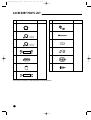
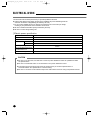
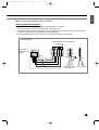
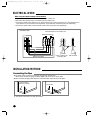
2008.10.20
11:5 PM
Page 17
INSTALLATION
MANUAL
FRANÇAIS
ESPAÑOL
APV48Q0AN
ENGLISH
APV48QOAN_E_IM_00000
FLOOR STAND TYPE AIR CONDITIONER
( Cooling and Heating )
E S F DB98-00000A(1)
APV48QOAN_E_IM_00000
2008.10.20
11:5 PM
Page 2
SAFETY PRECAUTIONS
Carefully follow the precautions listed below because they are essential to guarantee the safety of the equipment.)
WARNING
◆ Always disconnect the air conditioner from the power supply before servicing it or accessing its
internal components.
◆ Verify that installation and testing operations are performed by qualified personnel.
◆ Verify that the air conditioner is not installed in an easily accessible area.
GENERAL INFORMATION
◆ Carefully read the content of this manual before installing the air conditioner and store the manual in a safe place in
order to be able to use it as reference after installation.
◆ For maximum safety,installers should always carefully read the following warnings.
◆ Store the operation and installation manual in a safe location and remember to hand it over to the new owner if the
air conditioner is sold or transferred.
◆ This manual explains how to install an indoor unit with a split system with two SAMSUNG units.
The use of other types of units with different control systems may damage the units and invalidate the warranty.
The manufacturer shall not be responsible for damages arising from the use of non compliant units.
◆ The manufacturer shall not be responsible for damage originating from unauthorized changes or the improper
connection of electric and requirements set forth in the “Operating limits ” table,included in the manual,shall
immediately invalidate the warranty.
◆ The air conditioner should be used only for the applications for which it has been designed:the indoor unit is not
suitable to be installed in areas used for laundry.
◆ Do not use the units if damaged.If problems occur,switch the unit off and disconnect it from the power supply.
◆ In order to prevent electric shocks,fires or injuries,always stop the unit,disable the protection switch and contact
SAMSUNG ’s technical support if the unit produces smoke,if the power cable is hot or damaged or
if the unit is very noisy.
◆ Always remember to inspect the unit,electric connections,refrigerant tubes and protections regularly.
These operations should be performed by qualified personnel only.
◆ The unit contains moving parts,which should always be kept out of the reach of children.
◆ Do not attempt to repair,move,alter or reinstall the unit.If performed by unauthorized personnel,these operations
may cause electric shocks or fires.
◆ Do not place containers with liquids or other objects on the unit.
◆ All the materials used for the manufacture and packaging of the air conditioner are recyclable.
◆ The packing material and exhaust batteries of the remote control (optional)must be disposed of in accordance with
current laws.
◆ The air conditioner contains a refrigerant that has to be disposed of as special waste.At the end of its life cycle,
the air conditioner must be disposed of in authorized centers or returned to the retailer so that it can be disposed of
correctly and safely.
INSTALLING THE UNIT
IMPORTANT : When installing the unit,always remember to connect first the refrigerant tubes,then the electrical lines.
Always disassemble the electric lines before the refrigerant tubes.
◆ Upon receipt,inspect the product to verify that it has not been damaged during transport.If the product appears
damaged, DO NOT INSTALL it and immediately report the damage to the carrier or retailer (if the installer or the
authorized technician has collected the material from the retailer.)
E-2
2008.10.20
11:5 PM
Page 3
ENGLISH
APV48QOAN_E_IM_00000
◆ After completing the installation,always carry out a functional test and provide the instructions on how to operate
the air conditioner to the user.
◆ Do not use the air conditioner in environments with hazardous substances or close to equipment that release free
flames to avoid the occurrence of fires,explosions or injuries.
POWER SUPPLY LINE,FUSE OR CIRCUIT BREAKER
◆ Always make sure that the power supply is compliant with current safety standards.Always install the air conditioner
in compliance with current local safety standards.
◆ Always verify that a suitable grounding connection is available.
◆ Verify that the voltage and frequency of the power supply comply with the specifications and that the installed power
is sufficient to ensure the operation of any other domestic appliance connected to the same electric lines.
◆ Always verify that the cut-off and protection switches are suitably dimensioned.
◆ Verify that the air conditioner is connected to the power supply in accordance with the instructions provided in the
wiring diagram included in the manual.
◆ Always verify that electric connections (cable entry,section of leads,protections …)are compliant with the electric
specifications and with the instructions provided in the wiring scheme.Always verify that all connections comply with
the standards applicable to the installation of air conditioners.
Absolute Checkpoints
TABLE OF CONTENTS
1. Drain check
ACCESSORY PARTS LIST . . . . . . . . . 4
SELECTION OF INSTALLATION PLACE
• Indoor Unit . . . . . . . . . . . . . . . . . . . . 5
• Outdoor Unit . . . . . . . . . . . . . . . . . . 5
ELECTRICAL WORK . . . . . . . . . . . . . . 6
Drain hose
Indoor and outdoor
unit connection
2. Drilling a hole in the wall
INSTALLATION METHOD
• Connecting the Pipe . . . . . . . . . . . . 8
• Installation Procedures . . . . . . . . . . 9
• Connection of Refrigerant Piping . . 10
• Drilling a Hole in the Wall . . . . . . . . 11
• Drain Hose . . . . . . . . . . . . . . . . . . 11
AIR PURGE . . . . . . . . . . . . . . . . . . . . 12
REFRIGERANT CHARGING . . . . . . . 13
Ø70mm
Refer to page 11 for detailed procedures.
CHECK AND TEST OPERATION . . . 14
▼
▼
Less than
150mm
E-3
APV48QOAN_E_IM_00000
2008.10.20
11:5 PM
Page 4
ACCESSORY PARTS LIST
No.
Part Name
Remarks
No.
Part Name
1
Drain hose
8
Drain plug
2
Connecting pipe
9
Cable tie
10
Putty
ø9.52mm
(3/8 inch)
3
Connecting pipe
ø19.05mm
(3/4 inch)
4
Connection wiring (3 strand)
11
Pipe band
5
Insulation for piping
12
Cover hole
6
Finishing tape
13
Screw
7
Wire of sensor (2 strand)
❈ The type and quantity may differ depending on the specifications.
E-4
Remarks
APV48QOAN_E_IM_00000
2008.10.20
11:5 PM
Page 5
ENGLISH
SELECTION OF INSTALLATION PLACE
Indoor Unit
◆ Install the unit at a place close to the wall facing the outside as it is necessary to perform piping connection
with the outdoor unit.
- It is effective to install the unit at a window side to ensure uniform distribution of indoor temperature.
◆ Install the unit at a place where there is no obstacle against the wind around the air inlet and air outlet.
◆ Install the unit horizontally at a stable, rigid place.
(When installing the unit at a place subjected to oscillation, noise may occur.)
◆ Avoid a place near the door which is frequented by people.
◆ Avoid a place subject to direct sunlight.
◆ Do not push or hang on to the indoor unit. It may fall and cause personal injury.
Top view
Side view
Above 20cm
Above 50cm
Above 100cm
Outdoor Unit
Air outlet
◆ A place free from the risk of combustible gas leakage.
◆ A place which can bear the weight of the unit.
◆ A place which can bear the fixing strength of the outdoor unit.
◆ Avoid a place subject to oil (including machine oil).
◆ Avoid a saline place.
◆ Avoid a place subject to sulfide gas (hot spring zone).
(When installing the unit at such special environmental conditions, it may cause machine trouble.
When it is unavoidable to use such places, It requires special maintenance.)
◆ A place where the discharge air and noise of the outdoor unit do not disturb the neighborhood.
(Take special care not to cause any inconvenience to your neighbors when installing the unit on the
borderline with your neighborhood.)
◆ A place where strong wind does not head against the air outlet of the outdoor unit.
(If a strong wind heads directly against the air outlet at the time of cooling operation,
a safety device can be operated.)
◆ Do not install the outdoor unit at an unstable place such as outer wall of an apartment or building.
The outdoor unit may fall down, causing severe personal or property damage or loss.
❈ If there is any unavoidable reason to install the unit at such
a place, take the following measures against the wind;
Strong wind
1. When installing the unit at a roadside concentrated
with buildings, install it parallel with the road.
Wall
2. Install the unit so that the air outlet faces toward the wall at a
Roof top
place such as rooftop, which may be subjected to strong wind.
◆ The outdoor unit should be installed in accordance with the service space.
Above 50cm
Above 60cm
Above 30cm
Above 50cm
Space for piping
and wiring
The air inlet faces toward the wall.
Above 30cm
Space for piping
and wiring
Above 60cm
The air outlet faces toward the wall.
E-5
APV48QOAN_E_IM_00000
2008.10.20
11:5 PM
Page 6
ELECTRICAL WORK
The electrical work should be performed by a specialist qualified for the work.
◆ Use the three phase power supply, and be sure to install the sub power distributing board for
exclusive use with the unit(separately purchased by the user).
❈ Do not connect multiple plugs to an outlet at once because it can cause a drop in voltage,
resulting in poor performance of the automatic control circuit.
◆ Be sure to install circuit breaker (Extra purchased by the user).
◆ Be sure to connect the grounding wire.
❏ Electric power specification
Model
APV48Q0AN
1ø, 208~230V, 60Hz
Power
Ampere of breaker
50 A
Knife switch
Switch
30 A
Fuse
Size of grounding wire
30 A
2.0mm2
Min. size of electric wires from/to
the indoor/outdoor unit
0.75mm2
Size of electric input wires
4mm2
CAUTION
◆ Be sure to use the wires, and switches or fuses of power distribution board are qualified and fulfill
the specifications.
◆ Be sure to install knife switch or circuit breaker on the power distribution board.
◆ The electrical and grounding work should be performed as per ‘technical specifications of
electrical facilities’ and ‘specifications of internal wiring’.
◆ Be sure to connect the main electrical input wires with bolted connectors using compressed terminal.
E-6
2008.10.20
11:5 PM
Page 7
ENGLISH
APV48QOAN_E_IM_00000
❏ When connecting 3Phase 4wires 380V AC
When using NFB (No Fuse Breaker)
❈ The outdoor unit circuit is shipped based on the NFB power source wiring.
1. Remove the cover of electric box on side panel of the outdoor unit.
2. Connect the electric input wires (R,S,T,N) to each terminal (R,S,T,N) of the electric box on the outdoor unit
respectively. (Input wires are purchased by the user separately.)
3. Connect the electric wires to each terminal on the indoor and outdoor unit respectively.
OUTDOOR SIDE
Power terminals on the outdoor unit
Connector A
Knife switch or
automatic circuit
breaker
NFB
Electric input wires
Blue
Brown
Indoor / outdoor unit
connecting wire
Brown
Blue
Wire of sensor
E-7
APV48QOAN_E_IM_00000
2008.10.20
11:5 PM
Page 8
ELECTRICAL WORK
When using ELB (Earth Leakage Circuit Breaker)
1. Remove the cover of electric box on side panel of the outdoor unit.
2. Disconnect the connector A(R-L connection) from the outdoor unit.
3. Connect the electric input wires (R,S,T) to each terminal (R,S,T) and input wires (N,L) to each terminal (N,L)
of the electric box on the outdoor unit respectively. (Input wires are purchased by the user separately.)
4. Connect the electric wires to each terminal on the indoor and outdoor unit respectively.
OUTDOOR SIDE
Power terminals on the outdoor unit
Break Connector A
Blue
Brown
Indoor / outdoor unit
connecting wire
Electric input wires
INSTALLATION METHOD
Connecting the Pipe
◆ The piping of this unit can be connected to the right, left, and rear side.
When you hit the area for piping connection slightly with a hammer, a hole is made.
◆ After connecting the piping and drain hose, insert the rubber cap as shown in the figure.
Holes for piping
connection (2 points)
❈ The shape of hole may vary with the models.
E-8
Cover hole
Brown
Blue
Wire of sensor
APV48QOAN_E_IM_00000
2008.10.20
11:5 PM
Page 9
ENGLISH
INSTALLATION METHOD
Installation Procedures
1. Open the front panel, and remove the flare nut.
2. Bend the connection pipe to an appropriate length using the spring bender depending
upon the installation place.
- Allowable pipe length : Maximum 75m
- Allowable pipe drop distance : Maximum 30m
- Make no more than ten bending points on the pipe.
❈ When the pipe length is in excess of the standard pipe length of 7.5m, add the refrigerant (R410A) of
40g for each additional 1m.
❈ Additional Refrigerant
For example : 15m pipe length, additional refrigerant to be charged is (15m-7.5m)✕40g/m=300g
CAUTION
◆ If the pipe is lengthened, the performance of the unit is degraded, and the service life is shortened.
Therefore, the pipe length should be as short as possible (less than 25m).
Indoor unit
Indoor unit
Outdoor
unit
Outdoor
unit
Fix the pipe
Less than 6m
Less than 15m
Less than 15m
Indoor unit
S-TRAP
Outdoor
unit
Fix the pipe
(Every 6m)
3. Install the high pressure pipe to the heat exchanger liquid pipe, and the low pressure pipe to the
heat exchanger gas pipe respectively using the flare nut, taking care not to cause any leakage of refrigerant.
4. Be sure to insulate the pipe with appropriate insulation material.
5. Insert the drain hose into the drain pipe, and connect them by tying them to the cable tie to prevent
any water leakage.
6. After completion of the installation, check the connecting area for any gas leakage.
7. Wind a finish tape when the wiring of the refrigerant pipe, the unit, and the drain piping are completed.
Indoor unit
checking area
Outdoor unit
checking area
E-9
APV48QOAN_E_IM_00000
2008.10.20
11:5 PM
Page 10
INSTALLATION METHOD
Connection of Refrigerant Piping
❏ Flare Processing
1. Cut the pipe using the pipe cutter.
90
Oblique
Roughness
Burr
2. Insert the flare nut into the pipe, and then perform the flare processing.
A
Outer Diameter
A(mm)
9.52mm
1.8
19.05mm
2.2
❏ Pipe Bending
1. Perform bending of the pipe using the bender which has a specified bending
radius.
2. Be sure to take full care to perform bending of the pipe successfully at one
time. Bending and unbending the pipe more than twice makes the bending
work increasingly difficult.
3. You may use the spring inserted into the gas pipe instead of the bender to
bend the pipe.
4. When you bend the pipe using the spring, hold the pipe with both hands to
prevent any distortion, and secure a minimum bending radius of more than
100mm.
❏ Tightening of Connection Parts
◆ Align the center of the connection piping, and tighten the flare nut
by turning it with hand. Then tighten it again using the torque wrench
in the direction as shown in the figure.
E-10
Outer Diameter
Torque (kgf•cm)
9.52mm
250~280
19.05mm
990~1210
Remarks
Spring
2008.10.20
11:5 PM
Page 11
ENGLISH
APV48QOAN_E_IM_00000
Drilling a Hole in the Wall
◆ Drill a hole of 70mm in diameter to the outside.
◆ The drilling should be done at a distance of less than
150mm from the floor facing the indoor unit.
Less than
150mm
ø70mm
Drain Hose
◆ Extend the drain hose to the drain hose connected to
the drain pan, and fix it with the tape or a cable-tie to
prevent separation. Then make a covering of it so
that water cannot flow outwardly.
Drain pan
Insulation
Band
Piping Material
Vinyl Chloride
(Outer diameter ø16mm)
Insulator
Foamed Polyethylene
Drain hose
Indoor and outdoor
unit connection
CAUTION
1. As the draining is of natural drain type, make the drain hose direct downward.
2. If there is any foreign substance in the drain plate, it may clog the drain pipe. Therefore, be sure to
remove the foreign substance inside after installation.
3. After completion of installation, be sure to pour water into the drain pan, and then check the draining
condition. (There is no problem in draining when the draining is completed within 20 seconds.)
E-11
APV48QOAN_E_IM_00000
2008.10.20
11:5 PM
Page 12
AIR PURGE
❈ Be sure that all valve cocks are closed.
◆ The air in the indoor unit and in the pipe must be purged. If air remains in the refrigeration pipes, it will affect the
compressor, reduce to cooling capacity and could lead to a malfunction.
Use Vacuum Pump as shown at the figure.
1. Connect each assembly pipe to the appropriate valve on the outdoor unit and tighten the flare nut.
2. Connect the charging hose of low pressure side of manifold gauge to the packed valve having a service port
as shown at the figure.
3. Open the valve of the low pressure side of manifold gauge counter-clockwise.
4. Purge the air from the system using vacuum pump for about 30 minutes.
- Close the valve of the low pressure side of manifold gauge clockwise.
- Make sure that pressure gauge show -0.1MPa(-76cmHg) after about 30 minutes.
- This procedure is very important in order to avoid gas leak.
- Turn off the vacuum pump.
- Remove the hose of the low pressure side of manifold gauge.
5. Set valve cork of both liquid side and gas side of packed valve to the open position.
6. Mount the valve stem nuts and the service port cap to the valve, and tighten them at the torque of 183kgf•cm with
a torque wrench.
7. Check for gas leakage.
- At this time, especially check for gas leakage from the 3-way valve’s stem nuts, and from the service port cap.
Gas
pipe side
OUTDOOR UNIT
Indoor unit
Liquid
pipe side
D
A
B
C
Liquid
pipe side
Gas
pipe side
3-way
valve
3-way
valve
Flare nut
Valve cock
Cap
Needle valve cap
E-12
Vacuum
Pump
B
A
Outdoor unit
APV48QOAN_E_IM_00000
2008.10.20
11:5 PM
Page 13
ENGLISH
REFRIGERANT CHARGING
Purge air (at the time of new installation only).
Close the gas pipe side valve by turning it
clockwise.
Connect the pressure gauge to the low
pressure side service valve, and then open
the gas pipe side valve again.
Connect it to the refrigerant filling tank.
OUTDOOR UNIT
Gas
pipe side
Start cooling operation.
Check the pressure of the pressure gauge.
Check whether the low pressure side is within
the range of 8.2~9.3kg/cm2G
(outside temperature 35°C).
Liquid
pipe side
Open the tank and refill the refrigerant
until arriving at the proper pressure.
(Refill the refrigerant slowly checking the pressure.)
Stop operation.
Close the gas pipe side valve, and loosen
the pressure gauge connected.
Then open the gas pipe side valve again.
Tighten the cap of each valve using
a specified tool.
CAUTION
◆ Always use R410A refrigerant to avoid damage of
the unit or an explosion.
◆ Must keep the quantity of refrigerant by using a
balance. Do not use a manometer or not depend
on your experiences.
E-13
APV48QOAN_E_IM_00000
2008.10.20
11:5 PM
Page 14
CHECK AND TEST OPERATION
Check
◆ Be sure to check the following again after completion of installation.
1. Check the piping connection area for any gas leakage.
Outdoor
connection area
Indoor
connection area
2. Is the drain hose properly connected?
Drain hose
3. Is the insulation of the piping in good condition?
Insulation
E-14
Indoor and
outdoor unit connection
4. Is grounding properly made?
2008.10.20
11:5 PM
Page 15
ENGLISH
APV48QOAN_E_IM_00000
Test Operation
◆ After checking, read the owner’s instructions carefully, and perform a test operation.
Then deliver the unit to the customer.
(When delivering the unit, be sure to read carefully and follow the contents of the owner’s instructions.)
CAUTION
1. Be sure to check whether the service valve is opened before attempting to perform
the test operation.
2. Never attempt to start test operation by force pressing the electronic contactor as
it is very dangerous.
(This is very dangerous as the protective device does not work.)
3. Be sure to perform the test operation after installation.
It is easy to start the test operation in winter if you increase the sensor temperature to
23°C~25°C by holding the indoor temperature sensor. (Cooling operation)
❈ When the outdoor temperature is below zero, do not test operation for more than 3 minutes.
Otherwise, the compressor will be damaged.
Temperature sensor
E-15
APV48QOAN_E_IM_00000
2008.10.20
11:5 PM
Page 16
ELECTRONICS