1
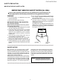
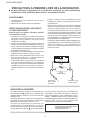
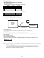
TopPage PG-F211X/PG-F261X SERVICE MANUAL No. S57K1PG-F211X MULTIMEDIA PROJECTOR MODELS PG-F211X PG-F261X In the interests of user-safety (Required by safety regulations in some countries) the set should be restored to its original condition and only parts identical to those specified should be used. OUTLINE This Service Manual covers the differences from XG-F210X. For other technical information, refer to the XR-30S/ XR-30X/XG-F210X (No. S47E3XR-30XS/) Service Manual. CONTENTS OUTLINE AND MODIFIED PARTS LIST OUTLINE.............................................................i MODIFIED PARTS ..............................................i CHAPTER 2. ELECTRICAL ADJUSTMENT [1] ELECTRICAL ADJUSTMENT .......................2-1 [2] Adjustment mode process menu ...................2-4 SAFETY PRECAUTION IMPORTANT SERVICE SAFETY NOTES...............................................................ii Precautions for using lead-free solder ............. vii Parts Guide CHAPTER 1. OPERATION MANUAL [1] Specifications ................................................. 1-1 Parts marked with " " are important for maintaining the safety of the set. Be sure to replace these parts with specified ones for maintaining the safety and performance of the set. This document has been published to be used for after sales service only. The contents are subject to change without notice. PG-F211X/PG-F261X PGF211X OUTLINE AND MODIFIED PARTS LIST Service Manual OUTLINE This Service Manual covers the differences from XG-F210X. For other technical information, refer to the XR-30S/XR-30X/XG-F210X (No. S47E3XR30XS/) Service Manual. MODIFIED PARTS (XG-F210X → PG-F211X/PG-F261X) Ref.No. Description PRINTED WIRING BOARD ASSEMBLIES BALLAST POWER Ass'y BALLAST CONTROL Unit PHOTO SENSOR Unit R/C RECEIVER Unit XG-F210X PG-F211X/PG-F261X Note DSETUE149FMG0 ← - DUNTKE150WEF0 ← - DUNTKE151WEF0 DUNTKE152WEF0 ← ← DUNTKE153FMF6 (PG-F211X) DUNTKE153FMF7 (PG-F261X) ← MAIN Unit DUNTKE153FMF4 (XG-F210X) DMD Unit DUNTKE154WEF0 CABINET AND MECHANICAL PARTS : Please refer to a Parts Guide. OPTICAL MECHANISM PARTS : Please refer to a Parts Guide. SUPPLIED ACCESSORIES : Please refer to a Parts Guide. PACKING PARTS AND ACCESSORIES : Please refer to a Parts Guide. SERVICE JIGS AND EQUIPMENT(USE FOR SERVICING) : Please refer to a Parts Guide. i No parts changed No parts changed - PG-F211X/PG-F261X PGF211X SAFETY PRECAUTION Service Manual IMPORTANT SERVICE SAFETY NOTES IMPORTANT SERVICE SAFETY NOTES (for USA) Service work should be performed only by qualified service technicians who are thoroughly familiar with all safety checks and servicing guidelines as follows: Use an AC voltmeter with sensitivity of 5000 ohm per volt., or higher, sensitivity to measure the AC voltage drop across the resistor. All checks must be repeated with the AC plug connection reversed. (If necessary, a non-polarized adapter plug must be used only for the purpose of completing these checks.) Any reading of 0.4 volts RMS (this corresponds to 0.27 milliamp. AC.) or more is excessive and indicates a potential shock hazard which must be corrected before returning the unit to the owner. WARNING 1. For continued safety, no modification of any circuit should be attempted. 2. Disconnect AC power before servicing. BEFORE RETURNING THE PROJECTOR: (Fire & Shock Hazard) Before returning the projector to the user, perform the following safety checks: 1. Inspect lead wires are not pinched between the chassis and other metal parts of the projector. 2. Inspect all protective devices such as non-metallic control knobs, insulating materials, cabinet backs, adjustment and compartment covers or shields, isolation resistor-capacity networks, mechanical insulators, etc. 3. To be sure that no shock hazard exists, check for current leakage in the following manner: Plug the AC cord directly into a 120 - volt AC outlet, (Do not use an isolation transformer for this test). Using two clip leads, connect a 1.5k ohm, 10 watt resistor paralleled by a 0.15µF capacitor in parallel between all exposed metal cabinet parts and earth ground. DVM AC SCALE 1.5k ohm 10W 0.15 µF TEST PROBE TO EXPOSED METAL PARTS CONNECT TO KNOWN EARTH GROUND ///////////////////////////////////////////////////////////////////////////////////////////////////////////////////////////////////////////////// SAFETY NOTICE R Many electrical and mechanical parts in DLP Projector have special safety-related characteristics. These characteristics are often not evident from visual inspection, nor can protection afforded by them be necessarily increased by using replacement components rated for higher voltage, wattage, etc. Replacement parts which have these special safety characteristics are identified in this manual; electrical components having such features are identified by “ ” and shaded areas in the Replacement Parts Lists and Schematic Diagrams. For continued protection, replacement parts must be identical to those used in the original circuit. The use of a substitute replacement parts which do not have the same safety characteristics as the factory recommended replacement parts shown in this service manual, may create shock, fire or other hazards. WARNING: The bimetallic component has the primary conductive side exposed. Be very careful in handling this component when the power is on. ///////////////////////////////////////////////////////////////////////////////////////////////////////////////////////////////////////////////// ii PG-F211X/PG-F261X PRECAUTIONS A PRENDRE LORS DE LA REPARATION Ne peut effectuer la réparation qu' un technicien spécialisé qui s'est parfaitement accoutumé à toute vérification de sécurité et aux conseils suivants. AVERTISSEMENT Utiliser un voltmètre CA d'une sensibilité d'au moins 5000Ω/V pour mesurer la chute de tension en travers de la résistance. Toucher avec la sonde d'essai les pièces métalliques exposées qui présentent une voie de retour au châssis (antenne, coffret métallique, tête des vis, arbres de commande et des boutons, écusson, etc.) et mesurer la chute de tension CA en-travers de la résistance. Toutes les vérifications doivent être refaites après avoir inversé la fiche du cordon d'alimentation. (Si nécessaire, une prise d'adpatation non polarisée peut être utilisée dans le but de terminer ces vérifications.) La tension de pointe mesurèe ne doit pas dépasser 0.4V (correspondante au courant CA de pointe de 0.27mA). Dans le cas contraire, il y a une possibilité de choc électrique qui doit être supprimée avant de rendre le récepteur au client. 1. N'entreprendre aucune modification de tout circuit. C'est dangereux. 2. Débrancher le récepteur avant toute réparation. VERIFICATIONS CONTRE L'INCEN-DIE ET LE CHOC ELECTRIQUE Avant de rendre le récepteur à l'utilisateur, effectuer les vérifications suivantes. 1. Inspecter tous les faisceaux de câbles pour s'assurer que les fils ne soient pas pincés ou qu'un outil ne soit pas placé entre le châssis et les autres pièces métalliques du récepteur. 2. Inspecter tous les dispositifs de protection comme les boutons de commande non-métalliques, les isolants, le dos du coffret, les couvercles ou blindages de réglage et de compartiment, les réseaux de résistance-capacité, les isolateurs mécaniques, etc. 3. S'assurer qu'il n'y ait pas de danger d'électrocution en vérifiant la fuite de courant, de la facon suivante: Brancher le cordon d'alimentation directem-ent à une prise de courant de 120 - V. (Ne pas utiliser de transformateur d'isolation pour cet essai). A l'aide de deux fils à pinces, brancher une résistance de 1.5 kΩ 10 watts en parallèle avec un condensateur de 0.15µF en série avec toutes les pièces métalliques exposées du coffret et une terre connue comme une conduite électrique ou une prise de terre branchée à la terre. DVM ECHELLE CA 1.5k ohm 10W 0.15 µF SONDE D'ESSAI AUX PIECES METALLIQUES EXPOSEES BRANCHER A UNE TERRE CONNUE ///////////////////////////////////////////////////////////////////////////////////////////////////////////////////////////////////////////////////// AVIS POUR LA SECURITE De nombreuses pièces, électriques et mécaniques, dans les projecteur à DLP présentent des caractéristiques spéciales relatives à la sécurité, qui ne sont souvent pas évidentes à vue. Le degré de protection ne peut pas être nécessairement augmentée en utilisant des pièces de remplacement étalonnées pour haute tension, puissance, etc. Les pièces de remplacement qui présentent ces caractéristiques sont identifiées dans ce manuel; les pièces électriques qui présentent ces particularités sont identifiées par la marque “ ” et hachurées dans la R liste des pièces de remplacement et les diagrammes schématiques. Pour assurer la protection, ces pièces doivent être identiques à celles utilisées dans le circuit d’origine. L’utilisation de pièces qui n’ont pas les mêmes caractéristiques que les pièces recommandées par l’usine, indiquées dans ce manuel, peut provoquer des électrocutions, incendies ou autres accidents. AVERTISSEMENT: La composante bimétallique dispose du conducteur primaire dénudé. Faire attention lors de la manipulation de cette composante sous tension. ///////////////////////////////////////////////////////////////////////////////////////////////////////////////////////////////////////////////////// iii PG-F211X/PG-F261X NOTE TO SERVICE PERSONNEL NOTE POUR LE PERSONNEL D’ENTRETIEN ////////////////////////////////////////////////////////////// UV-RADIATION PRECAUTION ////////////////////////////////////////////////////////////// ////////////////////////////////////////////////////////////// PRECAUTION POUR LES RADIATIONS UV ////////////////////////////////////////////////////////////// The light source, lamp, in the projector emits small amounts of UV-Radiation. La source de lumière, la lampe, dans le projecteur émet de petites quantités de radiation UV. AVOID DIRECT EYE AND SKIN EXPOSURE. EVITEZ TOUTE EXPOSITION DIRECTE DES YEUX ET DE LA PEAU. To ensure safety please adhere to the following: Pour votre sécurité, nous vous prions de respecter les points suivants: 1. Toujours porter des lunettes de soleil lors d’un entretien du projecteur avec la lampe allumée et le haut du coffret retiré. 1. Be sure to wear sun-glasses when servicing the projector with the lamp turned “on” and the top enclosure removed. 2. Ne pas faire fonctionner la lampe à l’extérieur du boîtier de lampe. 2. Do not operate the lamp outside of the lamp housing. 3. Ne pas faire fonctionner plus de 2 heures avec le coffret retiré. 3. Do not operate for more than 2 hours with the enclosure removed. Précautions pour les radiations UV et la lampe moyenne pression UV-Radiation and Medium Pressure Lamp Precautions 1. Toujours débrancher la fiche AC lors du remplacement de la lampe. 2. Laisser l’unité refroidir pendant une heure avant de procéder à l’entretien. 3. Ne remplacer qu’avec une lampe du même type. Type AN-XR30LP, caractéristique 200W-DC. 4. La lampe émet de petites quantités de radiation UVéviter tout contact direct avec les yeux. 5. La lampe moyenne pression implique un risque d’explosion. Toujours suivre les instructions d’installation décrites ci-dessous et manipuler la lampe avec soin. 1. Be sure to disconnect the AC plug when replacing the lamp. 2. Allow one hour for the unit to cool down before servicing. 3. Replace only with same type lamp. Type AN-XR30LP rated 200W DC. 4. The lamp emits small amounts of UV-Radiation, avoid direct-eye contact. 5. The medium pressure lamp involves a risk of explosion. Be sure to follow installation instructions described below and handle the lamp with care. iv PG-F211X/PG-F261X //////////////////////////////////////////////////////////////// //////////////////////////////////////////////////////////////// PRECAUTION POUR LES RADIA TIONS UV (Suite) UV-RADIATION PRECAUTION (Continued) //////////////////////////////////////////////////////////////// //////////////////////////////////////////////////////////////// Lamp Replacement Remplacement de la lampe Note: Remarque: Since the lamp reaches a very high temperature during units operation replacement of the lamp should be done at least one hour after the power has been turned off. (to allow the lamp to cool off.) Installing the new lamp, make sure not to touch the lamp (bulb) replace the lamp by holding its reflector 2 . [Use original replacement only.] Comme la lampe devient très chaude pendant le fonctionnement de l’unité, son remplacement ne doit être effectué au moins une heure après avoir coupé l’alimentation (pour permettre à la lampe de refroidir). En installant la nouvelle lampe, s’assurer de ne pas toucher la lampe (ampoule). Remplacer la lampe en tenant son réflecteur 2 . [N’utiliser qu’un remplacement d’origine.] 1 Lampe 1 Lamp 2 Reflecteur 2 Reflector DANGER ! –– Never turn the power on without the lamp to avoid electric-shock or damage of the devices since the stabilizer generates high voltages at its start. DANGER ! –– Ne jamais mettre sous tension sans la lampe pour éviter un choc électrique ou des dommages des appareils car le stabilisateur génère de hautes tensions à sa mise en route. Since small amounts of UV-radiation are emitted from an opening between the exhaust fans, it is recommended to place the cap of the optional lens on the opening during servicing to avoid eye and skin exposure. Comme de petites quantités de radiation UV sont émises par une ouverture entre les ventilateurs aspirants, il est recommandé de placer le capuchon de l’optique optionnelle sur l’ouverture pendant l’entretien pour éviter une exposition des yeux et la peau. v PG-F211X/PG-F261X WARNING: High brightness light source, do not stare into the beam of light, or view directly. Be especially careful that children do not stare directly into the beam of light. WARNING: TO REDUCE THE RISK OF FIRE OR ELECTRIC SHOCK, DO NOT EXPOSE THIS UNIT TO MOISTURE OR WET LOCATIONS. CAUTION The lighting flash with arrowhead within a triangle is intended to tell the user that parts inside the product are risk of electric shock to persons. RISK OF ELECTRIC SHOCK. DO NOT REMOVE SCREWS EXCEPT SPECIFIED USER SERVICE SCREW. CAUTION: TO REDUCE THE RISK OF ELECTRIC SHOCK, DO NOT REMOVE CABINET. NO USER-SERVICEABLE PARTS EXCEPT LAMP UNIT. REFER SERVICING TO QUALIFIED SERVICE PERSONNEL. The exclamation point within a triangle is intended to tell the user that important operating and servicing instructions are in the manual with the projector. CAUTION (POWER Unit) 6.3A 250V For continued protection against a risk of fire, replace only with same type 6.3A, AC250V fuse. (F701) AVERTISSEMENT: Source lumineuse de grande intensité. Ne pas fixer le faisceau lumineux ou le regarder directement. Veiller particulièrement à éviter que les enfants ne fixent directement le faisceau lumineux. AVERTISSEMENT: AFIN D’EVITER TOUT RISQUE D’INCENDIE OU D’ELECTROCUTION, NE PAS PLACER CET APPAREIL DANS UN ENDROIT HUMIDE OU MOUILLE. ATTENTION L’éclair terminé d’une flèche à l’intérieur d’un triangle indique à l’utilisateur que les pi‘eces se trouvant dans l’appareil sont susceptibles de provoquer une décharge électrique. RISQUE D’ÉLECTROCUTION. NE PASR ETIRER LES VIS Á L’EXCEPTION DE LA VIS DE REPARATION UTILISATEUR SPECIFIEES Le point d’exclamation à l’intérieur d’un triangle indique à l’utilisateur que les instructions de fonctionnement et d’entretien sont détaillées dans les documents fournis avec le projecteur. ATTENTION: POUR EVITER TOUT RISQUE D’ELECTROCUTION, NE PAS RETIRER LE CAPOT. AUCUNE DES PIECES INTERIEURES N’EST REPARABLE PAR L’UTILISATEUR, A L’EXCEPTION DE L’UNITE DE LAMPE. POUR TOUTE REPARATION, S’ADRESSER A UN TECHNICIEN D’ENTRETIEN QUALIFIE. PRECAUTION (Unité de PUTSSANCE) Pour une protection continue contre un risques d’incendie, ne remplacer qu’avec un fusible 6.3A,AC250V 6.3A 250V du même type. (F701) vi PG-F211X/PG-F261X Precautions for using lead-free solder Employing lead-free solder • "PWBs" of this model employs lead-free solder. The LF symbol indicates lead-free solder, and is attached on the PWBs and service manuals. The alphabetical character following LF shows the type of lead-free solder. Example: LFa Indicates lead-free solder of tin, silver and copper. Using lead-free wire solder • When fixing the PWB soldered with the lead-free solder, apply lead-free wire solder. Repairing with conventional lead wire solder may cause damage or accident due to cracks. As the melting point of lead-free solder (Sn-Ag-Cu) is higher than the lead wire solder by 40 °C, we recommend you to use a dedicated soldering bit, if you are not familiar with how to obtain lead-free wire solder or soldering bit, contact our service station or service branch in your area. Soldering • As the melting point of lead-free solder (Sn-Ag-Cu) is about 220 °C which is higher than the conventional lead solder by 40 °C, and as it has poor solder wettability, you may be apt to keep the soldering bit in contact with the PWB for extended period of time. However, Since the land may be peeled off or the maximum heat-resistance temperature of parts may be exceeded, remove the bit from the PWB as soon as you confirm the steady soldering condition. Lead-free solder contains more tin, and the end of the soldering bit may be easily corroded. Make sure to turn on and off the power of the bit as required. If a different type of solder stays on the tip of the soldering bit, it is alloyed with lead-free solder. Clean the bit after every use of it. When the tip of the soldering bit is blackened during use, file it with steel wool or fine sandpaper. • Be careful when replacing parts with polarity indication on the PWB silk. Lead-free wire solder for servicing Part No. ZHNDAi123250E ZHNDAi126500E ZHNDAi12801KE Description J J J φ0.3mm 250g(1roll) φ0.6mm 500g(1roll) φ1.0mm 1kg(1roll) Code BL BK BM vii PG-F211X/PG-F261X CHAPTER 1. OPERATION MANUAL PGF211X Service Manual [1] Specifications Model Display device Resolution Lens Input terminal Output terminal Control, others XG-F211X/PG-F261X 0.55" DLP Chip XGA (1024 x 768) F number Zoom Focus DVI-I (Compatible with HDCP) RGB/Component (mini D-sub 15 pin) S-Video (mini DIN 4 pin) Video (RCA) Audio (ø3.5 mm stereo minijack) Audio (RCA) RGB/Component (mini D-sub 15 pin) Audio (ø3.5 mm stereo minijack) USB (Type B) RS-232C (mini DIN 9 pin) Speaker Projection lamp Rated voltage Rated frequency Input current Power consumption (Standby) Operation temperature Cabinet Dimensions (main body only) Weight (approx.) F 2.5 – 2.6 Manual, x 1.15 (f = 20.4 – 23.5 mm) Manual x1 x1 x1 x1 x1 x 1 (L/R) x1 x1 x1 x1 2 W (Mono) 200 W AC 100 – 240 V 50/60 Hz 2.9 A 283 W (4.3 W) with AC 100 V 270 W (4.4 W) with AC 240 V 41°F to 95°F (+5°C to +35°C) Plastic 10 41/64" x 3 33/64" x 10 7/16" (270 (W) x 89 (H) x 265 (D) mm) 6.4 lbs. (2.9 kg) As a part of policy of continuous improvement, SHARP reserves the right to make design and specification changes for product improvement without prior notice. The performance specification figures indicated are nominal values of production units. There may be some deviations from these values in individual units. 1–1 PG-F211X/PG-F261X CHAPTER 2. ELECTRICAL ADJUSTMENTService PGF211X Manual [1] ELECTRICAL ADJUSTMENT No. 1 Adjusting point EEPROM initialization Adjusting conditions 1. Turn on the power (with the lamp on) and warm up the set for 15 minutes. 2 Model setting 3 Adjustment of CW index (Process menu) 1. Select the following group and subject. Group: CONFIRM Subject: MODEL 1. Signal input: Send 256 STEP color bar. XGA series (XGA60HZ), 2. Select the following group and subject. Group: ADJUST CW/Auto KS Subject: CW-INDEX. Adjusting procedure •Make the following settings. Press S2551 to call the process mode and execute "SS2" on SS menu. 1. Set as below. PG-F211X : 6 PG-F261X : 7 1. The signal is input into computer 1. 2. Select the adjustment item and adjust the lamp gradation patterns of RGBW so that smooth patterns without noise appear. W R G B 4 R/G/B contrast adjustment (manual or automatic) 1. Select the following group and subjects. Group : ADJUST AD/DLP Subject : R-CONT G-CONT B-CONT (Process GAMMA interlock) 2. Amplitude level 96% (0.67Vpp) the signal is input into computer 1. XGA series (XGA60HZ) 5 RGB white balance adjustment 6 sRGB white balance adjustment 1. 50% gray pattern signal is input into computer 1. XGA series (XGA60HZ) 2. Select the following group and subjects. Group : ADJUST AD/DLP Subject : R-GAIN G-GAIN B-GAIN 1. 50% gray pattern signal is input into computer 1. XGA series (XGA60HZ) 2. Select the following group and subjects. Group : CONFIRM/DLP Subject : S-G-OS S-B-OS 1. Measure chromaticity of the 96% white wind pattern using CA100. 2. On the screen where bit dropouts occur, raise the values of R/G/B-Contrast. Adjust the values so that bright red, green, and blue bit dropouts appear on a black background; and amounts of change in x value of R and y values of G/B become 100/1000 or more. 3. If adjustment is performed manually watching the screen, make adjustment so that bright red, green, and blue bit dropouts appear on more than half of the screen. 1. Raise the values of two of R/G/B-GAIN (default: 100) so that the following chromaticity values are obtained using CL200. x value: 295 ± 5 y value: 310 ± 5 1. Adjust S-G-OS and S-B-OS so that the following chromaticity values are obtained using CL200. x value: 313 ± 5 y value: 329 ± 5 Check items No. 1 Adjusting point 1 Adjustment of RGB brightness Adjusting conditions 1. Select the following group and subjects. Group : CONFIRM/AD Subject : R-BRIGHT G-BRIGHT B-BRIGHT (Process GAMMA interlock) 2–1 Adjusting procedure 1. Check the fixed value. Fixed value : 127 PG-F211X/PG-F261X No. 2 Adjusting point Adjustment of Component offset Adjusting conditions 1. Feed 10-step signal with 480P component 100% amplitude. 2. Select the following group and subjects. Group : CONFIRM/AD Subject : C-R-OS C-B-OS (Process GAMMA interlock) 1. Select the following group and subject. Group : CONFIRM/DLP Subject :R-BLK G-BLK B-BLK (Process GAMMA interlock) 1. Feed NTSC 100% wind pattern signal. (Signal with burst) 2. Select the following group and subjects. Group : CONFIRM/VIDEO Subject : V-CONT 1. Feed NTSC 100% wind pattern signal. (Signal with burst) 2. Select the following group and subject. Group : CONFIRM/VIDEO Subject : V-BRIGHT 1. Feed split color bar. 2. Select the following group and subject. Group : CONFIRM/VIDEO Subject : V-HUE 1. Select the following group and subject. Group : CONFIRM/VIDEO Subject : V-COLOR 1. Feed the SMPTE pattern signal. 3 Adjustment of DLP Brightness 4 Video Contrast adjustment 5 Adjustment of Video Brightness 6 Adjustment of Video Tint 7 Adjustment of Video color saturation 8 RGB tone reproduction adjustment 9 VIDEO white balance adjustment 10 White balance checking and readjustment 11 Off-timer performance 12 13 Thermistor performance checking 1. Heat the thermistor with a hair dryer. Auto sync performance checking 1. Feed the phase check pattern signal. 14 DVI input operation check Send the video signal to the DVI terminal. 15 Monitor out check 16 RS232C operation check 1. Send signals to COMPUTER 1 and COMPUTER 2. 2. Connect another monitor to the monitor out. 3. Connect the audio OUT. 1. Connect the unit and a PC with the RS232C cable. 1. Feed the 50% gray signal. 2. Select the following group and subjects. Group :CONFIRM/VIDEO Subject : V-R-OS V-B-OS 1. RGB Input sRGB Input VIDEO Input DTV Input DVD Input 1. Select the following group and subjects. Group :CONFIRM/CHECK Subject : TEMP-OFF 2–2 Adjusting procedure 1. Check the fixed value. C-R-OS : 257 C-B-OS : 257 1. Check the fixed value. Fixed value : 256 1. Check the fixed value. Fixed value : 124 1. Check the fixed value. Fixed value : 68 1. Check the fixed value. Fixed value : 128 1. Check the fixed value. Fixed value : 154 1. Make sure the 100% and 95% white as well as the 0% and 5% black gradations are visible. 1. V-R-OS is 132. V-B-OS is 132. Check that there is no deviation of white balance with the monitor. 1. Select OFF from the process mode. Make sure the off-timer starts with 5 minutes onscreen and count one minute in one second. And then indication is 0 minute, the power supply of the set is cut off. 1. Make sure that the temperature is indicated. 1. In the VGA, SVGA, XGA and SXGA modes, make sure the Clock, Phase, H-Pos and V-Pos settings can be automatically adjusted. 1. For PG-F211X/PG-F261X, check that an image is properly projected through the digital input and analog input. 1. Check that the same images as seen on the screen appear on the connected monitor and that the sound from the sound source connected to the audio OUT is heard. 1. Send a command from the PC, and check it functions correctly. PG-F211X/PG-F261X No. 17 Adjusting point Model name and version check Adjusting conditions 1. Select the following group. Group : INFO/VERSION. 18 Setup guide screen check 19 Delivery settings 1. Turn on the power after making the setup guide display ON setting or factory setting (SS4, etc.). 1. Make the following settings. Destination USA * Process adjustment SS4 Adjusting procedure 1. The model name appears in the MODEL field, and the firmware version in the VERSION field. Check that they are correct. 1. Check that the 4-split screen is displayed correctly and the display contents are correct. Remote control adjustment Factory setting at 4 Writing a software program (before main PWB is mounted) Use the DLP Composer Lite Ver. 4.2 to download the firmware. After writing the specified version of firmware to the PWB using the RS232C cable, check the version of the written firmware. If no software program is written, all three LEDs light up in the chassis inspection process. Calling and quitting the process mode with the control keys on this model. * Although it is possible for the process OUT to exit using the process menu, the IN/OUT toggle command is also available considering the existing specification. 1) Calling and quitting With the menu not displayed, press the "ENTER", "ENTER", "VOL+", "VOL-", "ENTER", "ENTER" and "MENU" keys on the remote control or on the main unit. 2) Others Press the S2551 process key (toggle) on the main PWB to call and quit the process menu. NOTE: When adjusting in the process mode, set a signal with a vertical frequency of 60 Hz or no signal. (May not be properly adjusted with other signals.) Resetting the lamp timer for this model 1) Resetting procedure In Stand-by, run this command to clear the operating time of the lamp to 0 and turn on the power. Press and hold " ", "ENTER", and "MENU", and then press the "STANDBY/ON" key of the set. Forced disabling of the System-Lock of this model 1) Disabling procedure With System-Lock input window onscreen, press the "MENU", "ENTER", "ENTER", "MENU", "ENTER", "ENTER" and "MENU" keys, in this order, on the remote controller. 2–3 PG-F211X/PG-F261X [2] Adjustment mode process menu 1st Layer ADJUST CW/Auto KS AD/DLP SS CONFIRM AD DLP VIDEO MODEL CHECK INFO VERSION PATTERN LAMP TEMP/FAN 2nd Layer CW-INDEX CAL K-SENS R-CONT G-CONT B-CONT R-GAIN G-GAIN B-GAIN SS1 SS2 SS3 SS4 SS5 SS6 R-BRIGHT G-BRIGHT B-BRIGHT C-R-OS C-B-OS R-BLK G-BLK B-BLK S-R-OS S-G-OS S-B-OS V-CONT V-BRIGHT V-COLOR V-HUE V-R-OS V-G-OS V-B-OS OFFSET-MODE OFFSET-CONT OFFSET-BRI MODEL-SELECT LED-CHK TEMP-OFF MODEL VER. RGB RGB50 CORSS STEP COLOR CHR CURRENT HISTORY1 HISTORY2 HISTORY3 HISTORY4 TOTAL TEMP1 TEMP2 FAN0 FAN1 FAN2 Default 20 1st Layer OTHER (0) 110 110 110 100 100 100 — — — — — — 127 127 127 257 257 256 256 256 128 128 128 124 68 154 128 132 128 132 0 0 0 0 0 — — — 1 1 1 1 1 1 0 0 0 0 0 0 — — 3 3 3 SPECIAL EDID EXIT 2–4 2nd Layer USB-MODE HDCP-MODE PULSE-MODE EEP-SELECT EEP-WP Default 0 0 0 1 0 PG-F211X/PG-F261X 1. Adjustment of ballast unit output power (lamp power) 1. List of parts requiring adjustment When replacing the following parts, adjust the ballast unit output power (lamp power). 1 2 3 4 5 Part name Cement resistor Ballast Control PWB Ballast microprocessor 5V regulator Ballast Switching Control Ref No. R923 —— IC7707 IC7704 IC7701 Part code RR-FZA002WJZZ DUNTKE150WEF0 RH-iXC103WJZZQ VHiTA78L05F-1Y VHiM51995AF-1Y 2. Adjustment jigs The following jigs are required for adjusting the ballast unit output power (lamp power). 1 2 Part name Adjustment jig (resistance load 25 Ω) Connecting cord (conversion cable) Part code RUNTZA018WJZZ QCNWKA020WJZZ 3. Ballast unit output power (lamp power) adjustment method Adjust the ballast unit output power (lamp power) in the following method. [Setting method] Tester (Voltage) PG-F211X PG-F261X Ballast Unit Lamp Cable Projector TP1 Connecting Cord (QCNWKA020WJZZ) Adjustment Jig (RUNTZA018WJZZ) TP2 2. Adjustment method 1) Unplug the ballast unit lamp cable of the projector from the lamp and connect the cable to the connecting cord (QCNWKA020WJZZ). 2) Connect the connecting cord (QCNWKA020WJZZ) to the adjustment jig (RUNTZA018WJZZ). 3) Connect TP1 of the adjustment jig (RUNTZA018WJZZ) to the negative terminal of the tester and TP2 to the positive terminal. 4) Turn on the projector. 5) Check the Lamp setting to “Bright”. 6) Ageing the projector for 60 seconds or more. 7) Adjust the volume resistor (R7805) of the ballast control PWB (DUNTKE150WEF0) so that the voltage of the tester reaches 71±0.5V. Adjustment value: 71±0.5V CAUTION: (1) Caution for electric shock: Do not touch the test points TP1 and TP2 of the adjustment jig when supplying power since a high voltage and large current is applied to them. (2) Caution for heat: Be careful that the resistance load of the adjustment jig produces a high temperature when supplying power. (3) Connection of the lamp cable: Check that the lamp cable and connecting cord (QCNWKA020WJZZ) are connected securely. Poor connection may cause smoking or ignition due to arc discharge. 2–5 PG-F211X/PG-F261X PartsGuide PARTS GUIDE No. S57K1PG-F211X MULTIMEDIA PROJECTOR MODELS PG-F211X PG-F261X Note: The reference numbers on the PWB are arranged in alphabetical order. CONTENTS [1] PRINTED WIRING BOARD ASSEMBLIES [2] CABINET AND MECHANICAL PARTS [3] OPTICAL MECHANISM PARTS [4] SUPPLIED ACCESSORIES [5] PACKING PARTS (NOT REPLACEMENT ITEM) [6] SERVICE JIGS AND EQUIPMENT (USE FOR SERVICING) Parts marked with " " are important for maintaining the safety of the set. Be sure to replace these parts with specified ones for maintaining the safety and performance of the set. This document has been published to be used for after sales service only. The contents are subject to change without notice. PG-F211X/PG-F261X NO. PARTS CODE PRICE NEW PART RANK MARK DELIVERY DESCRIPTION [1] PRINTED WIRING BOARD ASSEMBLIES N DSETUE149FMG0 BZ J N Not Available - - N N N N N N DUNTKE150WEF0 DUNTKE151WEF0 DUNTKE152WEF0 DUNTKE153FMF6 DUNTKE153FMF7 DUNTKE154WEF0 BW AY AY CT CT CN N N N N J J J J J J BALLAST POWER Ass'y (with Ballast Control Unit) BALLAST POWER Unit Order the BALLAST POWER Ass'y (DSETUE149FMG0) when replacing ballast power unit (DUNTKE149WEF0). BALLAST CONTROL Unit PHOTO SENSOR Unit R/C RECEIVER Unit MAIN Unit (PG-F211X) MAIN Unit (PG-F261X) DMD Unit (without the DMD chip) 2 PG-F211X/PG-F261X [2] CABINET AND MECHANICAL PARTS 1-4 18 10 1 10 30 1-3 40 42 25 10 1-1 31 40 19 1-2 1-5 29 10 17 23 43 24 45 6 15 12 39 22 44 32 39 14 33 2-6 38 2-4 8 2-10 2-11 40 34 9 40 2-5 2-3 27 2-2 2 16 4 41 5 40 2-1 2-1-3 2-9 2-8 37 2-1-1 26 2-1-2 3 2-7 PG-F211X/PG-F261X NO. PARTS CODE PRICE NEW PART RANK MARK DELIVERY DESCRIPTION [2] CABINET AND MECHANICAL PARTS ! 1 1 1-1 1-2 1-3 1-4 1-5 2 2 2-1 2-1-1 2-1-2 2-1-3 2-2 2-3 2-4 2-5 2-6 2-7 2-8 2-9 2-10 2-11 4 5 6 8 9 10 12 14 15 16 17 18 19 22 23 24 25 26 27 29 30 31 32 33 34 37 38 39 40 41 42 43 44 45 CBDYTA264WEF0 CBDYTA265WEF0 Not Available GCOVAC364WJSA HDECPA034WJSA HiNDPC319WJSC GCOVAC242WJKC CBDYUA304WEF0 CBDYUA305WEF0 CDORUA075WEF0 Not Available LX-BZA185WJFN PSLDHA047WJFW Not Available LX-NZ3120CEFW LX-NZ3144CEFW LX-NZA014WJFW QEARPA250WJFW GLEGPA030WJSA GLEGPA036WJSA PSPAZB478WJZZ QCNW-F721WJQZ XEBSN30P10000 ----AN-XR30LP LHLDFA011WJKZ LHLDZA849WJKZ LX-BZ3049GEFN LX-BZ3100CEF7 LX-BZA186WJF9 NFANRA076WJ00 NFANRA078WJ00 PCOVPA037WJSA PCOVUA105WJ00 PCOVZA099WJZZ PCOVZA100WJZZ PSLDMB118WJFW PSLDMB119WJFW PSLDMB122WJFW PSLDMB123WJFW PSPAGA370WJKZ PSPAGA371WJKZ PZETKA227WJKZ PZETKA233WJKZ PZETKA240WJKZ QCNW-F711WJQZ QCNW-F718WJPZ QCNW-F720WJQZ RSP-ZA085WJQZ XBBSN30P06000 XBPSN30P08JS0 XEBSN30P10000 Not Available PCOVWA015WJKZ QEARPA256WJFW QCNW-G254WJQZ NSFTZ0134CEFW BP BP AE AK AM AS BT BT AQ AB AK AB AC AC AK AK AP AC AN AA AC AQ AB AA AD BM BP AU AF AE AF AM AK AZ AX AP AW AX AD AG AZ AY AG AP AA AB AA AC AB AH AD N N N N N N N N N N N N N N N N N N N N N N N N N N N N N N N N N N N N N N J J J J J J J J J J J J J J J J J J J J J J J J J J J J J J J J J J J J J J J J J J J J J J J J J J J Top Body Ass'y (PG-F211X) Top Body Ass'y (PG-F261X) Top Body Cover Decoration Plate Indicator Cover Bottom Body Ass'y (PG-F211X) Bottom Body Ass'y (PG-F261X) Lamp Door Ass'y Lamp Door Screw Shield Bottom Body Nut Nut, x4 Nut Bottom Earth Shield Foot (Rear Adjuster) Foot (Front Adjuster) Spacer Connecting Cord Screw Refer to Optical Mechanism Parts Lamp Unit Rivet (Power PWB) Holder (Bimetal) Screw, x4 Screw, x7 Screw, x2 Fan Fan Cover Cover Cover Cover Shield Shield Shield Shield Spacer Spacer Insulator Insulator Insulator Connecting Cord Connecting Cord Connecting Cord Speaker Screw Screw, x3 Screw, x18 Serial No Label Spacer Ground-Part Connecting Cord Shaft for DVI Socket, x2 4 PG-F211X/PG-F261X [3] OPTICAL MECHANISM PARTS 4-33 11 11 11 13 13 4-33 4-11 4-33 11 13 20 13 21 7 4-27 28 4-33 4-33 4-25 35 4-16 36 4-24 4-29 4-36 4-33 4-34 4-33 4-13 4-34 4-8 4-33 4-33 4-12 4-33 4-33 4-31 4-31 4-33 4-31 4-31 4-5 4-26 4-6 4-33 4-31 4-28 4-31 4-18 4-31 4-33 4-7 4-20 4-21 4-30 4-15 4-33 4-22 4-31 4-33 4-17 4-2 4-32 4-23 4-1 4-32 4-32 4-4 4-3 4-35 4-35 4-19 4-33 4-14 4-33 4-33 4-33 4-10 4-9 4-33 4-33 5 PG-F211X/PG-F261X NO. PARTS CODE PRICE NEW PART RANK MARK DELIVERY DESCRIPTION [3] OPTICAL MECHANISM PARTS 4-1 4-2 4-3 4-4 4-5 4-6 4-6 4-7 4-8 4-9 4-10 4-11 4-12 4-13 4-14 4-15 4-16 4-17 4-18 4-19 4-20 4-21 4-22 4-23 4-24 4-25 4-26 4-27 4-28 4-29 4-30 4-31 4-32 4-33 4-34 4-35 4-36 7 11 13 20 21 28 35 36 LANGKB121WJFW LCHSKA024WJFW LHLDZA845WJKZ LX-EZA027WJFN MSPRPA095WJFW MSPRPA096WJFW MSPRPA103WJFW MSPRPA097WJFW NFANRA077WJ00 PCOVPA036WJSA PCOVPA038WJSA PCOVZA089WJFW PCOVZA093WJKZ PCOVZA094WJKZ PCOVZA095WJFW PCOVZA096WJFW PDUC-A088WJFW PFiLWA120WJZZ PLNS-A059WJZZ PLNS-A080WJZZ PLNS-A083WJZZ PLNS-A084WJZZ PLNS-A085WJZZ PMiR-A125WJZZ PRDARA446WJFW PSLDHA048WJFW PSLDPA077WJFW PSLDPA072WJKZ PSLDPA073WJFW RH-HXA040WJQZ TLABZB026WJZZ XBBS925P06000 LX-BZA205WJFN XBBSN30P06000 XBPSN30P20JS0 XEPSN17P05000 PSLDPA078WJFW LHLDZA612WJFW LX-BZA110WJF7 MSPRCA062WJFJ PRDARA445WJFW PSHEGA040WJZZ PSPAZA768WJZZ QSOCZA114WJZZ RDMDPA027WJZZ AE BQ AN AC AF AG AG AK BH AR AS AP AM AN AL AG AF CC BF AT AT AT BD AU AQ AK AM AZ AD AS AE AA AA AA AB AB AF AL AC AB AZ AE AD BA CW N N N N N N N N N N N N N N N N N N N N N N N N N N N N N N N N N J J J J J J J J J J J J J J J J J J J J J J J J J J J J J J J J J J J J J J J J J J J J J Fixing Metal Chassis Holder For Focus Ring, x3 Spring Spring (PG-F261X) Spring (PG-F211X) Spring Fan Cover Cover Cover Cover Cover Cover C/W Cover Exhaust Duct Filter Lens Lens Lens Lens Lens Mirror Heat Sink Shield Shield Shield Shield Thermistor No. Label Screw, x9 Screw, x3 Screw, x22 Screw, x2 Screw, x2 Flat Ray Shield Holder (Backer Plate) Screw, x4 Spring, x4 Heat Sink Sheet Spacer Socket DMD Chip, 0.55" XGA 6 PG-F211X/PG-F261X [4] SUPPLIED ACCESSORIES X1 X3 X6 X4 X2 X5 X9 X10 * NO. PARTS CODE PRICE NEW PART RANK MARK DELIVERY DESCRIPTION [4] SUPPLIED ACCESSORIES ! X1 X2 X3 X4 X5 X6 X7 X8 X9 X10 CCAPHA027WJSA GCASNA021WJSA QACCDA007WJPZ QCNWGA045WJPZ QCNWGA091WJPZ RRMCGA581WJSA TGAN-A811WJZZ TGAN-A840WJZZ TiNS-D338WJZZ UDSKAA094WJZZ AH BD AR AU AZ BD AB AC AN AQ N N N N N N N J J J J J J J J J J Lens Cap Storage case AC Cord (for U.S.A) RGB Cable DIN-D-sub RS-232C adaptor Remote Control SECL Warranty (for Canada) SEC Warranty (for USA) Operation Manual CD-ROM 7 PG-F211X/PG-F261X [5] PACKING PARTS (NOT REPLACEMENT ITEM) S5 S6 S2 S8 S3 S4 S7 S1 8 PG-F211X/PG-F261X NO. PARTS CODE PRICE NEW PART RANK MARK DELIVERY DESCRIPTION [5] PACKING PARTS (NOT REPLACEMENT ITEM) S1 S1 S2 S3 S4 S5 S6 S7 S8 SPAKCD746WJZZ SPAKCD747WJZZ SPAKFB224WJZZ SPAKPA869WJZZ SPAKXB477WJZZ SSAKA0160CEZZ SSAKAA097WJZZ TLABVA333WJZZ TLABV0003SEZZ - N N N N N N N - Packing Case (PG-F211X) Packing Case (PG-F261X) Accessory Case Wrapping Paper Packing Add Polyethylene Bag Polyethylene Bag (for Storage case) Bar Code Label Model Name Label [6] SERVICE JIGS AND EQUIPMENT (USE FOR SERVICING) N N N N N N QCNW-C516WJQZ QCNWKA006WJZZ QCNWKA008WJZZ QCNWKA019WJZZ RUNTZA018WJZZ QCNWKA020WJZZ AG AX AP BU DR AX J J J J J J Extension Cable, 3pins L=200mm, Main to Fan, x2 Extension Cable, 4pins L=500mm, Main to Fan Extension Cable, 14pins, Main to Power Extension Cable, 120pins, Main to DMD Adjustment Jig, for the Ballast Unit Extension Cable, 3 to 2pins 9 PG-F211X/PG-F261X COPYRIGHT © 2007 2006 BY SHARP CORPORATION ALL RIGHTS RESERVED. No Part of this publication may be reproduced, stored in a retrieval system, or transmitted in any from or by any means, electronic, mechanical, photocopying , recording, or otherwise, without prior written permission of the publisher. TQ2242-S YK. DS SHARP CORPORATION AV Systems Group CS Promotion Center Yaita,Tochigi 329-2193, Japan