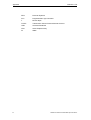
1
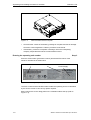
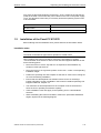
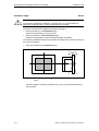
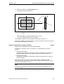
Preface, Contents SIMATIC PC Panel PC 670 Panel PC 870 Start-Up Instructions Unpacking and Installing the Panel PC 670/870 1 Connecting and Switching On the Panel PC 670/870 2 Operating the Panel PC 670/870 3 Electromagnetic Compatibility 4 General information 5 Appendix This Start-Up Instructions manual is valid for the following units: Panel PC 670: Order Number 6AV77xx-... Panel PC 870: Order Number 6AV77xx-xC... and 6AV77xx-xD... Release 11/02 A5E00174923 Safety Guidelines This manual contains notices which you should observe to ensure your own personal safety, as well as to protect the product and connected equipment. These notices are marked as follows according to the level of danger: Danger indicates an imminently hazardous situation which, if not avoided, will result in death or serious injury. Warning indicates a potentially hazardous situation which, if not avoided, could result in death or serious injury. Caution used with the safety alert symbol indicates a potentially hazardous situation which, if not avoided, may result in minor or moderate injury. Caution used without the safety alert symbol indicates a potentially hazardous situation which, if not avoided, may result in property damage. Notice indicates that unwanted events or status can occur if the relevant information is not observed. Note draws your attention to particularly important information on the product, handling the product, or to a particular part of the documentation. Qualified Personnel Equipment may be commissioned and operated only by qualified personnel. Qualified personnel within the meaning of the safety notices in this manual are persons who are authorized to commission, ground and identify equipment, systems and circuits in accordance with safety engeneering standards. Correct Usage Please note the following: Warning The device may only be used for the application cases specified in the catalog and the technical description and may only be used in combination with third-party equipment and components recommended or approved by Siemens. Startup must not take place until it is established that the machine which is to accommodate this component is conforms with the guideline 98/37 EC. Appropriate transport, and appropriate storage, installation and assembly, as well as careful operation and maintenance, are required to ensure that the product operates perfectly and safely. Trademarks The registered trademarks of the Siemens AG can be found in the preface. Impressum Editor and Publisher: A&D PT1 Copyright Siemens AG 2002 All rights reserved Exclusion of Liability The transmission and reproduction of this documentation and the exploitation and communication of its contents are not permitted without express authority. Offenders will be liable for compensation for damage. All rights reserved, especially in the case of the granting of a patent or registration of a utility model or design. We have checked the content of this publication for compliance with the described hardware and software. However, discrepancies cannot be excluded, with the result that we cannot guarantee total compliance. The information in this publication is, however, checked regularly, and any necessary corrections are included in the following editions. We welcome any suggestions for improvement. Siemens AG Bereich Automation & Drives Geschäftsgebiet SIMATIC HMI Postfach 4848, D-90327 Nürnberg Siemens AG 2002 Technical data subject to change. Siemens Aktiengesellschaft Order No. A5E00174923 1Preface Purpose This Start-Up Instructions manual is a component part of the documentation for the SIMATIC Panel PC 670 and SIMATIC Panel PC 870 (subsequently referred to as Panel PC 670/870). This Start-Up Instructions manual contains the information for installation engineers and system operators necessary for the mechanical and electrical installation of the Panel PC 670/870 and starting it up. Caution The contents of the Panel PC 670/870 Start-Up Instructions are superordinated to those of the Equipment Manual of the Panel PC 670/870. Siemens AG assumes no liability resulting from failure to observe the instructions. Documentation • Start-Up Instructions (this document). The Start-Up Instructions manual is supplied in printed form together with the Panel PC 670/870 and is available in German, English, French, Italian and Spanish. The Start-Up Instructions manual is also provided in the languages mentioned in electronic PDF format on the Documentation & Drivers CD. • SIMATIC Panel PC 670/870, operating unit equipment manual The equipment manual contains information on operating the operating unit, error diagnostics and the hardware. Target groups include installation engineers as well as service and maintenance technicians. • SIMATIC Panel PC 670, computer unit equipment manual SIMATIC Panel PC 870, computer unit equipment manual The equipment manual contains information on extension options for the computer unit, on the configuration, error diagnostics and the hardware. All the equipment manuals mentioned are supplied with the Panel PC 670/870 electronically in PDF format on the Documentation & Drivers CD and are available in German, English, French, Italian and Spanish. Target groups include installation engineers as well as service and maintenance technicians. SIMATIC Panel PC 670/870 Start-Up Instructions iii Preface Release 11/02 Notation Different font formats simplify orientation within the text: The text on the screen of the operating unit is displayed in typewriter font. Inputs and outputs on the screen of the operating unit are displayed in italic typewriter font. Menu items, dialog names, tab controls and buttons of the operating system and the application are displayed in italic font. In context with menu items the complete path is always described. Motor on Output File → Edit Note The content of this Start-Up Instructions is organized according to the sequence of work necessary and, thus, stucturally corresponds to a working plan subdivided into the individual working steps. The work involved is identified by the heading Step x and chronologically ordered according to the sequence of steps. All the other chapters and sections serve to provide information before performing the respective step. Trademarks The following names are registered trademarks of the Siemens AG: • • • • • • • • • ® SIMATIC ® SIMATIC HMI ® SIMATIC Multi Panel ® SIMATIC Multifunctional Platform ® SIMATIC Panel PC ® HMI ® ProTool ® ProTool/Lite ® ProTool/Pro The remaining trademarks in this publication may be trademarks, whose use by third parties for their own purposes could violate the rights of the owner. iv SIMATIC Panel PC 670/870 Start-Up Instructions Release11/02 Preface Customer and Technical Support Available worldwide: Nuremberg Johnson City Singapore SIMATIC Hotline Worldwide (Nuremberg) Worldwide (Nuremberg) Technical Support Technical Support (FreeContact) (fee-based, only with SIMATIC Card) Local time: Mon.–Fri. 8:00 to 17:00 Local time: Mon.–Fri. 0:00 to 24:00 Telephone: +49 (180) 5050-222 Telephone: +49 (911) 895-7777 Fax: +49 (180) 5050-223 Fax: +49 (911) 895-7001 E-Mail: techsupport@ ad.siemens.de GMT: +01:00 GMT: +1:00 Europa/Africa (Nuremberg) America (Johnson City) Asia/Australia (Singapore) Authorization Technical Support and Authorization Technical Support and Authorization Local time: Mon.–Fri. 8:00 to 17:00 Local time: Mon.–Fri. 8:00 to 19:00 Local time: Mon.–Fri. 8:30 to 17:30 Telephone: +49 (911) 895-7200 Telephone: +1 423 461-2522 Telephone: +65 740-7000 Fax: +49 (911) 895-7201 Fax: +1 423 461-2289 Fax: +65 740-7001 E-Mail: authorization@ nbgm.siemens.de E-Mail: simatic.hotline@ sea.siemens.com E-Mail: simatic.hotline@ sae.siemens.com.sg GMT: +1:00 GMT: -5:00 GMT: +8:00 The languages spoken by the SIMATIC Hotlines are generally German and English – the Authorization Hotline is also provided in French, Italian and Spanish. SIMATIC Panel PC 670/870 Start-Up Instructions v Preface Release 11/02 SIMATIC Customer Support Online Services The SIMATIC Customer Support team offers you substantial additional information about SIMATIC products via its online services: • General current information can be obtained – In the Internet under http://www.siemens.com/simatic • Current Product Information leaflets, FAQs (Frequently Asked Questions), Downloads, Tips and Tricks can be obtained – In the Internet under http://www.siemens.com/automation/service&support Training Center Siemens offers a number of training courses to familiarize you with the SIMATIC S7 automation system. Please contact your regional training center or our central training center in D 90327 Nuremberg, Germany for details. Telephone: +49 (911) 895-3200 Internet: http://www.sitrain.com E-Mail: info@sitrain.com Other Sources of Assistance In case of technical queries, please contact the Siemens representatives in the subsidiaries and branches responsible for your area. The addresses can be found: vi • In the Siemens Catalog ST 80 • In the Internet under http://www.siemens.com/automation/partner • In the Interactive Catalog CA01 http://www.siemens.com/automation/ca01 SIMATIC Panel PC 670/870 Start-Up Instructions Contents 1 Unpacking and Installing the Panel PC 670/870 .............................. 1–1 1.1 1.2 1.3 2 3 Unpacking and Checking the Delivery Contents ............................................. 1–1 Installation of the Panel PC 670/870................................................................ 1–3 Installation of the Computer Unit.................................................................... 1–11 Connecting and Switching On the Panel PC 670/870 ..................... 2–1 2.1 2.2 2.3 2.4 2.5 2.6 Interfaces ......................................................................................................... 2–1 Operating Units with Keypad Fronts ................................................................ 2–4 Operating Units with Touchscreen Fronts........................................................ 2–5 Power Supply ................................................................................................... 2–6 Initial Startup .................................................................................................... 2–7 Operating System .......................................................................................... 2–10 2.6.1 Windows 98 (only applies to Panel PC 670).................................................. 2–11 2.6.2 Windows NT 4.0 TM....................................................................................... 2–12 2.6.3 Windows 2000................................................................................................ 2–14 2.6.4 Windows XP................................................................................................... 2–15 2.6.5 2.7 2.8 Operating system not installed....................................................................... 2–16 Installing Additional User Software ................................................................ 2–17 Use of USB Peripheral Devices ..................................................................... 2–18 Operating the Panel PC 670/870 ....................................................... 3–1 3.1 3.2 3.3 Normal Operation............................................................................................. 3–1 Data Backup and Restoring the Operating System ......................................... 3–2 Additional Drivers and Applications ................................................................. 3–5 3.3.1 Documentation & Drivers CD........................................................................... 3–5 3.3.2 Touchware settings .......................................................................................... 3–5 3.3.3 Keypad ........................................................................................................... 3–10 3.3.4 SIMATIC SOM (safecard on motherboard) ................................................... 3–11 3.3.5 TouchInputPC ................................................................................................ 3–12 3.3.6 Setdisplay....................................................................................................... 3–12 3.3.7 Setbrightness ................................................................................................. 3–13 3.3.8 KeyHook......................................................................................................... 3–14 3.3.9 CheckLanguageID ......................................................................................... 3–15 3.3.10 Language settings.......................................................................................... 3–16 SIMATIC Panel PC 670/870 Start-Up Instructions vii Contents Release 11/02 4 Electromagnetic Compatibility.......................................................... 4–1 5 General Information ........................................................................... 5–1 Appendix ........................................................................................................... a viii SIMATIC Panel PC 670/870 Start-Up Instructions 1 Unpacking and Installing the Panel PC 670/870 1.1 1 Unpacking and Checking the Delivery Contents Unpacking Step 1 • Check the packaging of the Panel PC 670/870 for visible signs of transport damage. If signs of transport damage are apparent, contact the transporting company responsible immediately. • Open the packing and unpack the contents. Note Do not dispose of the original packaging – save it for a future transportation of the Panel PC 670/870. Keep all the documents supplied! They belong to the Panel PC 670/870 and are required for the initial startup. Checking Step 2 Figure 1–1 View of the Panel PC 670/870 12" operating unit with membrane keyboard SIMATIC Panel PC 670/870 Start-Up Instructions 1–1 Unpacking and Installing the Panel PC 670/870 Figure 1–2 Release 11/02 View of the Panel PC 670 computer • Check that the content of the delivery package is complete and free of damage. Check the content against the "delivery contents" list enclosed. • If the delivery content is incomplete or damage, inform the transporting company responsible and set the contents aside unused. Entering the operating unit number Step 3 Enter the SVP number (production number) and the MLFB number of the Panel PC 670/870 in the table below. MLFB Number Figure 1–3 SVP Number Version Power Supply Rating label (example) The SVP number and the MLFB number enable the operating unit to be identified by the service center in case of any repairs required. Both numbers are on the rating plate on the ventilation side at the top (refer to Figure 1–3). 1–2 SIMATIC Panel PC 670/870 Start-Up Instructions Release 11/02 Unpacking and Installing the Panel PC 670/870 Also enter the Microsoft Windows "Product Key" of the "Certificate of Authenticity" (COA) in the table. The Product Key can be found on the unit on the power supply cover. The Windows Product Key is necessary should the operating system need to be reinstalled. SVP number MLFB number Microsoft Windows Product Key 1.2 Installation of the Panel PC 670/870 Before starting with the installation work, please observe the information below: Installation notes Caution The Panel PC 670/870 is approved for operation in closed rooms. When installing the Panel PC 670/870, observe the information in Chapter "Technical Data" of the Panel PC 670 or Panel PC 870 Equipment Manual as well as the following points: • Place the screen in such a way that it is not exposed to direct radiation by sunlight or other light sources. • Place the screen in an ergonomic position for the user – select a corresponding installation height. • Position the operating unit and computer so that the air vents in the housing are not covered following installation. • Ensure that the cabinet/panel has sufficient volume for the air exchange. Further information on this is available in the Panel PC 670/870 Operating Unit Equipment Manual, Chapter 2.4. • The maximum air inlet temperature for the computer must not exceed 45°C when the unit is operating at maximum capacity. • These installation notes also apply to the operating unit in a decentralized structure. • When assembling the Panel PC 670/870, observe the permissible installation angles, depicted in the following diagram. SIMATIC Panel PC 670/870 Start-Up Instructions 1–3 Unpacking and Installing the Panel PC 670/870 Release 11/02 Installation angle Step 4 Warning If the Panel PC 670/870 is installed in a position which is not permissible, all approvals complying with UL 1950 and EN 60950 are annulled. The Panel PC 670/870 is available in two different designs: • Panel PC 670/870 in a centralized design – computer and operating unit from one unit. • Panel PC 670/870 in a decentralized design – computer and operating unit are assembled spatially separated. The following installation angles are permitted according to the respective design of the Panel PC 670/870: 1. Panel PC 670/870 in a centralized design +20° Figure 1–4 –20° Permissible installation angles for the Panel PC 670/870 in a centralized design Vertical installation as well as deviations up to ±20° in the indicated directions are permitted. 1–4 SIMATIC Panel PC 670/870 Start-Up Instructions Release 11/02 Unpacking and Installing the Panel PC 670/870 2. Panel PC 670/870 in a decentralized design Only applies to the operating unit: +70° Figure 1–5 –20° Permissible installation angles for the Panel PC 670/870 in a decentralized design Vertical installation as well as deviations up to +70° to –20° in the indicated directions are permitted. The installation position for the computer is described in Chapter 1.3. Select the installation angle according to your own needs and continue to the next step to define the degree of protection. Degree of protection and type of fixation Step 5 Applies to both centralized and decentralized designs: The degree of protection, which you decide on, is dependent on the type of fixation: • Protection Class IP65 This degree of protection is achieved by fixing the operating unit by means of clamping saddles together with a seal running around the circumference. • Protection Class IP54 This degree of protection is achieved by fixing the operating unit by means of screw mountings. Select the degree of protection in accordance with the intended use of the equipment and, thus, the type of fixation. After having made the selection, chose the necessary installation cut-out. Note The Panel PC 670/870, 12" touchscreen is not designed for installation using screw mountings. SIMATIC Panel PC 670/870 Start-Up Instructions 1–5 Unpacking and Installing the Panel PC 670/870 Release 11/02 Select installation cut-out Step 6 Apples to the computer in a decentralized design: No installation cut-out is required for the computer. Skip this working step. Applies to both centralized and decentralized designs: Select an appropriate installation area taking the installation notes and selected installation angle into account. Note Ensure sufficient air volume for heat transportation within the switching cabinet/panel. Further information on this is available in the Panel PC 670/870 Operating Unit Equipment Manual, Chapter 2.4. Also ensure sufficient free space to pull out the Panel PC 670/870 from the installation cut-out. When selecting the installation cut-out, ensure that the switching cabinet/panel contains reinforcement bars to stabilize the cut-out. If necessary, install such reinforcement bars. Figure 1–6 below contains: • the dimensioning of the holes required for the retaining screws and • the dimensioning of the pressure points of the screws regarding the clamping saddles. 1–6 SIMATIC Panel PC 670/870 Start-Up Instructions Release 11/02 Unpacking and Installing the Panel PC 670/870 A1 ±1 L3 ±1 S1 ±1 S2 ±1 112 ±0.5 Clamp with grub screws L3 ±1 A2 ± 1 112 ±0.5 L2 +1 Drill hole for screw fixings 112 ± 0.5 56 ± 1 L5 ± 0.2 Pressure points for clamps L1 +1 S1 ±1 Rz 120 (in gasket area) *) *) S1 ±1 M6/∅ ∅7 Gasket area L4 ±0.2 min. 1.5 – max. 6 Operating units L1 (a) with key-based front panels: 10.4"-TFT / 12.1"-TFT 15.1"-TFT (b) with touchscreen front panels: 12.1"-TFT 15.1"-TFT Figure 1–6 L2 L3 L4 L5 A1 A2 S1 S2 450 290 78 465 235 16 10 – – 450 321 51 465 279 16 17 – – 368 290 16 10 35 19 450 290 81 465 235 16 10 – – – – – *) cut-outs only for 15" TFT (8HE) Installation cut-out for Panel PC Refer to Figure 1–6 to check that the screws and pressure points on the rear side, and the shaded seal area are freely accessible after completion of the installation cut-out. Otherwise, it is possible that the installation cut-out cannot be used. When the conditions mentioned are fulfilled, complete the installation cut-out according to the next step. SIMATIC Panel PC 670/870 Start-Up Instructions 1–7 Unpacking and Installing the Panel PC 670/870 Release 11/02 Making the installation cut-out Step 7 Applies to both centralized and decentralized designs: Figure 1–7 below contains the dimensions for the installation cut-out for the Panel PC 670/870 or the operating unit in a decentralized design. 2 to 6 2 H+1 B+1 T+1 All specifications in mm. Unit depth T Unit depth T Design Centralized Decentralized B H PC 670 PC 870 PC 670 PC 870 Panel PC 670/870, 10” / 12", Keys Panel PC 670/870, 15", Keys 450 450 290 324 105 130 187 212 69 91 69 91 Panel PC 670/870, 12", Touch Panel PC 670/870, 15", Touch 368 450 290 290 130 130 – 212 85 91 85 91 Installation cut-out Figure 1–7 Dimensions for installation of the operating unit (specifications without the CD-ROM option) After completing the installation cut-out, insert the Panel PC 670/870 or operating unit in the cut-out and fix it according to the type of fixation selected (refer to Step 8). 1–8 SIMATIC Panel PC 670/870 Start-Up Instructions Release 11/02 Unpacking and Installing the Panel PC 670/870 Fixation Step 8 Fixation using clamping saddles Applies to both centralized and decentralized designs: Skip this working step if screw mounting fixation has been decided upon. The clamping saddles and threaded pins required for the installation are part of the material supplied in the delivery content. Proceed as follows: 1. Insert the Panel PC 670/870 or operating unit in the installation cut-out from the front. 2. From the back, fasten the operating unit in the installation cutout by tightening the setscrews (torque: 0.4 - 0.5 Nm) of the six clamps (see Figure 2–2). In the case of a decentralized design, secure the computer as described in Step 11. Otherwise, installation is complete. Refer to Chapters 2.1 to 2.3 for information concerning the position of the interfaces, the operating panel and the operating system. Then continue with Step 11. Fixation using screw mountings Applies to both centralized and decentralized designs: Skip this working step if clamping saddle fixation has been decided upon. Proceed as follows: 1. Drill appropriate holes in the installation cut-out in accordance with the specifications to L4 and L5 in Figure 1–6. 2. Carefully break out the drill hole caps on the front of the operating unit. Drill hole caps Figure 1–8 Drill holes with caps SIMATIC Panel PC 670/870 Start-Up Instructions 1–9 Unpacking and Installing the Panel PC 670/870 Release 11/02 3. Install the assembled operating and computer units or operating unit in the prepared installation cut-out from the front. 4. Fasten the operating unit with suitable nuts and bolts through the drill holes. The installation with screw mountings meets the IP54 degree of protection. In the case of a decentralized design, secure the computer as described in Step 11. Otherwise, installation is complete. Refer to Chapters 2.1 to 2.3 for information concerning the position of the interfaces, the operating panel and the operating system. Then continue with Step 11. 1–10 SIMATIC Panel PC 670/870 Start-Up Instructions Release 11/02 1.3 Unpacking and Installing the Panel PC 670/870 Installation of the Computer Unit Skip this chapter if the centralized design has been chosen. Only applies to the computer unit: Permissible installation positions for the computer unit complying with UL1950/EN60950/CSA22.2 No. 950 An angle of ± 20° is allowed in every permissible installation position. *) Position 1 (preferable position) Position 2 *) Position 3 (desktop) Position 4 (cover) **) Not permitted where an LS240 drive is installed. **) Not permitted where a disk/CD-ROM/LS240 drive is installed. Figure 1–9 Permissible installation positions for the computer unit in a decentralized design SIMATIC Panel PC 670/870 Start-Up Instructions 1–11 Unpacking and Installing the Panel PC 670/870 Release 11/02 Additional permissible installation position for the computer unit complying with UL508/CSA 22.2 No. 142 An installation angle of ±15° is permitted in this position. Position 5 (interfaces at bottom) Figure 1–10 Additionally permissible installation positions for the computer unit in a decentralized design Select an appropriate installation location taking the installation notes and selected installation angle into account. Note Ensure sufficient air volume for heat transportation within the switching cabinet/panel. Further information on this is available in the Panel PC 670/870 Operating Unit Equipment Manual, Chapter 2.4. Also ensure sufficient free space to pull out the Panel PC 670/870 from the installation cut-out. When selecting the installation location, ensure that the switching cabinet/panel contains reinforcement bars to stabilize the cut-out. If necessary, install such reinforcement bars. Figure 1–11 below contains the dimensioning for the holes for the screw mountings. 1–12 SIMATIC Panel PC 670/870 Start-Up Instructions Release 11/02 Unpacking and Installing the Panel PC 670/870 Step 9 5 286 Installation 26 Figure 1–11 232 Dimensions for installation of the computer unit Install the computer unit. Installation is complete. Refer to Chapters 2.1 to 2.3 for information concerning the position of the interfaces, the operating panel and the operating system. Then continue with Step 11. SIMATIC Panel PC 670/870 Start-Up Instructions 1–13 Unpacking and Installing the Panel PC 670/870 1–14 Release 11/02 SIMATIC Panel PC 670/870 Start-Up Instructions 2 2 Connecting and Switching On the Panel PC 670/870 2.1 Interfaces Computer unit 1 14 2 3 4 13 12 Figure 2–1 5 11 10 6 9 8 Interfaces on the Panel PC 670 computer unit 7 6 5 2 10 9 11 3 14 1 12 13 Figure 2–2 Interfaces on the Panel PC 870 computer unit SIMATIC Panel PC 670/870 Start-Up Instructions 2–1 Connecting and Switching On the Panel PC 670/870 1 Release 11/02 Mouse PS/2 socket for connecting a PS/2 mouse. 2 COM 1/Modem/Programmable Logic Controller (PLC) The COM 1 (TTY) interface can be used to connect e.g. S5 PLCs. By implementing the adapter supplied, the interface can also be used as a 25pin V.24 standard interface to connect devices with a serial interface, such as modem, mouse or printer. 3 COM 2 Serial interface 2 (V.24) to connect devices with a serial interface, such as modem, mouse or printer. 4 AC/DC power supply connection Device socket for AC voltage power supply or screw terminals for DC voltage power supply. 5 PCI expansion slot Internal slot for PCI expansion modules. 6 PCI/ISA expansion slot Internal slot for expansion modules. 7 ISA slot Internal slot for ISA expansion modules. 8 PC card (Panel PC 670 only) Connection for PC cards of the type I/II/III. 9 Ethernet RJ 45 Ethernet connection. The Ethernet network is a local network with a bus structure for data communication with data transmission rates of 10 or 100 Mbps. 10 PROFIBUS/MPI Using the potential isolated PROFIBUS/MPI interface, the Panel PC 670/870 can be connected to an S7 PLC or a PROFIBUS network. 11 USB 2 connections for Universal Serial Bus. Using the USB connection, it is possible to connect external devices, such as CD drives, printers, modems or mouse and keyboard. Also refer to Chapter 2.7. 12 VGA A VGA monitor can be connected here. 2–2 SIMATIC Panel PC 670/870 Start-Up Instructions Release 11/02 Connecting and Switching On the Panel PC 670/870 13 LPT1 The parallel interface serves to connect devices with a parallel interface, e.g. a printer. 14 Keyboard Connection for a PS/2 keyboard. Operating unit On the rear side of the operating unit (refer to Figure 2–3) are two flatband cables for connection to the computer unit: Display Cable K2 IO/USB Cable K1 Figure 2–3 Operating unit interfaces • The I/O USB cable K1 on X1 for all signals which is responsible for the connection of operating units in addition to the display interface. This cable is depicted in Figure 2–3 folded together and is approx. 20 mm longer than illustrated. • The display cable K2 General information Step 10 When the equipment is started up for the first time, it is necessary to connect a PS/2 keyboard and a PS/2 mouse. Connect the keyboard and mouse before switching on the Panel PC 670/870. Further information on the operating unit is provided in Chapters 2.2 and 2.3. SIMATIC Panel PC 670/870 Start-Up Instructions 2–3 Connecting and Switching On the Panel PC 670/870 2.2 Release 11/02 Operating Units with Keypad Fronts The front side of the Panel PC 670/870 is equipped with a membrane keyboard and mouse. The integrated USB mouse with two mouse buttons is a "piezo mouse", i.e. the direction of the mouse pointer movement is controlled by the position of pressure on the pressure surface, while the speed of the mouse pointer movement is controlled by the force of pressure applied. Optionally an external mouse can be connected to the USB port at the front. The piezo mouse remains active in this case. The arrangement of the operating elements is illustrated in Figure 2–4. Status indicators Function keys/Softkeys Alphanumeric, cursor and control keys Display USB interface Figure 2–4 Integrated mouse Front view of the operating unit Note The Panel PC 670/870 Documentation & Drivers CD contains several master files to create labeling strips with which to label the keys. These labeling strips can be edited and printed using MS Word, MS Excel or Coral Draw. Only the keyboard labeling strips, available on option, are suitable for printing using a laser printer. 2–4 SIMATIC Panel PC 670/870 Start-Up Instructions Release 11/02 Connecting and Switching On the Panel PC 670/870 Keyboard: The layout of the membrane keyboard is USA International. Please ensure that the layout of any other keyboard that may be connected also complies with this character set. Only those characters inscribed on the external keyboard match those displayed on the screen. Danger Simultaneously pressing more than one function key can trigger malfunctions on the Panel PC 670/870. Only press the function keys and softkeys in succession (refer to Figure 2–4). Also refer to Chapter 3.3.8. Continue with Chapter 2.4. 2.3 Operating Units with Touchscreen Fronts The 12” and 15” versions with touchscreen fronts differ with regard to their dimensions and display sizes. The 12” model has no drill hole caps on the side. Figure 2–5 illustrates an example of an operating unit with a 15” touchscreen front and operating indicators, USB interface and display. Status indicators Display USB interface Figure 2–5 Example of a 15.1” operating unit with touchscreen front SIMATIC Panel PC 670/870 Start-Up Instructions 2–5 Connecting and Switching On the Panel PC 670/870 Release 11/02 Operation The operating unit is operated by touching the touch-sensitive screen which contains application-specific functions, e.g. touching a button displayed. Continue with Step 11. 2.4 Power Supply Connection Step 11 The Panel PC 670/870 can be operated on AC-120/230 V power supplies. The voltage selection is performed automatically. Plug the power cable in the AC/DC power supply connection on the computer unit – in the case of a decentralized design, also in the operating unit's AC/DC power supply connection. Danger Since the operating unit does not have a power switch, turning off and completely disconnecting power requires pulling the power plug. This location should be easily accessible. For the installation in a cabinet, a central power disconnect switch must be provided. Notice As soon as power is supplied to the operating unit via the power supply connection, the BIOS and operating system installed are loaded. If the power supply is switched off during this routine, the operating unit is not shut down properly. The Scandisk program must then be activated. To prevent an unintentional unplugging of the power plug from the computer unit, we recommend using the power plug lock contained in the accessories kit. In the case of the decentralized design, the operating unit is provided with cable clips to fasten the power plug. Notice A ferrite core is contained in the material supplied with the Panel PC 670. Connect the ferrite core supplied directly behind the device socket of the power supply cable. The operating unit can also be supplied with a DC 24 V power supply, according to the order option. Plug the 3-point power supply connector into the socket on the Panel PC 670/870. Note the pin assignment depicted on the housing. When these steps have been completed, continue with Step 12. 2–6 SIMATIC Panel PC 670/870 Start-Up Instructions Release 11/02 2.5 Connecting and Switching On the Panel PC 670/870 Initial Startup Checklist Step 12 Before startup, go through the following checklist: • Have you considered the environmental conditions of the Panel PC 670/870 and the connected peripheral devices? • Are the peripheral devices connected properly and have all the required presettings been made? • Have you checked the connection to the power supply? Caution Risk of damage to the Panel PC 670/870! Ensure that no condensation is formed on or in the operating unit when transporting it during cold weather periods or when it is exposed to extreme temperature fluctuations. Before starting it up, the operating unit must be brought to room temperature slowly. In case of condensation, wait approximately 12 hours before switching the operating unit on. Switching on Step 13 Notice Before switching the operating unit on, refer to Chapters and 2.6 2.7 in respect of any special features to be taken into account which are dependent on the operating system installed and the periphery to be connected. After connecting the peripheral devices and the system unit, mains power can be applied to the Panel PC 670/870. Panel PC 670/870 in a centralized design: Connect the mains power cable to a socket with a grounding conductor or switch on the mains supply on the mains isolating switch. The green power LED lights up. The Panel PC 670/870 is then put into operation and the boot routine started. Panel PC 670/870 in a decentralized design: Connect the computer and operating units by means of the green connection cable "Cu-Link". Connect the decentralized operating unit to the mains power supply. The green power LED lights up. Connect the mains power cable to a socket with a grounding conductor or switch on the mains supply on the mains isolating switch. Note If there is no display signal (e.g. the "Cu-Link" plug is not connected), the operating unit has a "white" screen. The Panel PC 670/870 is then put into operation and the boot routine started. SIMATIC Panel PC 670/870 Start-Up Instructions 2–7 Connecting and Switching On the Panel PC 670/870 Release 11/02 License number Step 14 After connection to the mains, the Panel PC 670/870 performs a self-test. During the self-test, the message Press <F2> to enter SETUP appears briefly. After the self-test has been completed, the operating system is loaded. The "Welcome" page will be displayed. Follow the on-screen prompts. 1. Go to the next page. 2. Accept the license agreement and continue to the next page. 3. Enter the license number – if necessary – confirm it and switch to the next window. The system settings are then updated and the desktop is set up. 2–8 SIMATIC Panel PC 670/870 Start-Up Instructions Release 11/02 Connecting and Switching On the Panel PC 670/870 Screen resolution and panel type selection Step 15 After the system settings have been updated, the following dialog appears in which to select the screen resolution: Figure 2–6 Selecting the screen resolution Select the screen resolution corresponding to your device and confirm the selection with OK. Then select the panel type for the device: Figure 2–7 Selecting the panel type Select the panel type corresponding to your device. The system settings of the operating system are then updated according to the selections made. This finalizes the initial startup. SIMATIC Panel PC 670/870 Start-Up Instructions 2–9 Connecting and Switching On the Panel PC 670/870 2.6 Release 11/02 Operating System The Panel PC 670/870 is approved for the following operating systems: Panel PC 670 • Windows 98 SE, German/English • Windows NT 4.0 with USB driver extension, German/English • Windows 2000 Professional Multi-Language; German, English, French, Italian, Spanish, Japanese, Korean, Chinese (simplified), Chinese (traditional) • Windows XP Professional Multi-Language; German, English, French, Italian, Spanish, Japanese, Korean, Chinese (simplified), Chinese (traditional) Panel PC 870 • Windows NT 4.0 with USB driver extension, German/English • Windows 2000 Professional Multi-Language; German, English, French, Italian, Spanish Note In the case of high system utilization and/or high levels of network operation, it is generally recommended to use the Windows NT, Windows 2000 and Windows XP operating systems for the Panel PC 670/870. 2–10 SIMATIC Panel PC 670/870 Start-Up Instructions Release 11/02 Connecting and Switching On the Panel PC 670/870 2.6.1 Windows 98 (only applies to Panel PC 670) When the Panel PC 670 is started up for the first time, the system requests entry of the appropriate OEM license number during the operating system boot routine. Please refer to the label supplied for this information. After entering the license number, enter a name for the computer so that it can be identified within a network. Special features The Panel PC 670 is shipped with BIOS setting LEGACY SUPPORT DISABLED. That means the full functional range of a USB keyboard is not available during the initial boot sequence (before Windows is started). There are no restrictions for using a USB keyboard to make changes in the BIOS Setup. When using an operating panel with touchscreen front, changes can only be made to the BIOS using an externally connected USB or PS/2 keyboard. Following a faulty operation, e.g. uncontrolled system shutdown or power failure, the Panel PC 670 starts the Scandisk program during the subsequent boot routine. It is not possible for the user to stop this automatically started program using an integrated membrane keyboard or external USB keyboard. The following steps are recommended in order to interrupt this automatic process: 1. When Scandisk has been completed, switch the device off and on again. Windows reboots without any keyboard input. If Windows is not rebooted, switch the operating unit off again. Carry out the following steps: 2. Plug in the USB keyboard and switch on the power supply. 3. Press the "F2" key during the boot routine. 4. Select Hardware Options in the BIOS Setup and switch the LEGACY SUPPORT setting to ENABLED. The USB keyboard is also supported in Enabled mode. Notice If Legacy Support is activated in the BIOS (enabled), individual problems may occur with specific ISA/PCI extension boards. 5. After rebooting the system again, select Hardware Options in the BIOS Setup and switch LEGACY SUPPORT back to DISABLED. If Windows 98 is terminated and Start in MS DOS Mode is selected, input is only possible using an external PS/2 keyboard. Power management The default Power Saving setting Disabled must not be changed in the BIOS setup. SIMATIC Panel PC 670/870 Start-Up Instructions 2–11 Connecting and Switching On the Panel PC 670/870 Release 11/02 2.6.2 Windows NT 4.0 TM When a Panel PC 670/870 is started up for the first time, the system may request entry of the appropriate OEM license number during the operating system boot routine. Please refer to the label supplied for this information. After entering the license number, enter a name for the computer so that it can be identified within a network. It is advisable to enter an administrator password when using Microsoft Windows NT 4.0. Notice Do not forget that, when installing or restoring Windows NT 4.0, Service Pack 6a or higher must also be installed. DHCP utility The DHCP utility is set up during the installation of Windows NT. It is predefined as disabled. If the DHCP utility is to be used, it must be activated. 1. Select the buttons Start → Settings → Control Panel → Utilities. The Utilities window opens. 2. Select DHCP Client Utility. Double-clicking on it opens the Utility window. 3. Select the Automatic option button and confirm the selection with OK. 4. Close the window which is open. Check the entries relating to the computer name after ending the network configuration. 1. Select the buttons Start → Settings → Control Panel → Network → Protocols. 2. Select TCP/IP. A double-click opens the window Microsoft TCP/IP Properties. 3. Select the DNS tab control then option button Automatic and confirm the selections with OK. 4. The Host Name field contains the computer name; correct it as necessary and confirm using OK. USB Keyboardcontroller The USB Keyboardcontroller V1.0 driver is installed by default. It provides the following functions: • The LEDs on the integrated function keys can be controlled, e.g. using ProTool and WinCC. • Keyboard tables can be modified using the Keypad application (refer to Chapter 3.3.3). • The brightness of the back-lighting can be changed using the SetBrightness application (refer to Chapter 3.3.7). 2–12 SIMATIC Panel PC 670/870 Start-Up Instructions Release 11/02 Connecting and Switching On the Panel PC 670/870 BIOS settings The Panel PC 670/870 is shipped with BIOS setting LEGACY SUPPORT DISABLED. That means the full functional range of a USB keyboard is not available during the initial boot sequence (before Windows is started). There are no restrictions for using a USB keyboard to make changes in the BIOS Setup. When using an operating panel with touchscreen front, changes can only be made to the BIOS using an externally connected USB or PS/2 keyboard. The USB Legacy Support is preset to DISABLED in the BIOS Setup under menu item Hardware. The Windows NT 4.0 USB driver extension for use of the integrated membrane keyboard, mouse, and touchscreen has already been pre-installed. Selection of an operating menu when starting Windows NT 4.0 is only possible with an external PS/2 keyboard or by changing the BIOS option USB Legacy Support to ENABLED. Notice If Legacy Support is activated in the BIOS (enabled), individual problems may occur with specific ISA/PCI extension boards. Power management The default Power Saving setting Disabled must not be changed in the BIOS setup. Restrictions Only applicable to Panel PC 670/870 with keypad front panels: • The LEDs on an externally connected PS/2 keyboard have no function. • Only external USB keyboards without integrated HUB or standard USB mice (without special, additional functionality, e.g. wheel) are approved for connection to the front side USB interface and the USB interface on the computer. Service Pack The following Service Pack is required: • Windows NT: Service Pack 6a Service Pack 6a is contained with the Panel PC 670/870 supplied. In the case of a new installation of Windows NT, the Windows NT Service Pack must be installed before all other additional drivers. After a driver has been installed, the Service Pack must be reinstalled. SIMATIC Panel PC 670/870 Start-Up Instructions 2–13 Connecting and Switching On the Panel PC 670/870 Release 11/02 2.6.3 Windows 2000 When a Panel PC 670/870 is started up for the first time, the system may request entry of the appropriate license number during the operating system boot routine. After entering the license number, enter a name for the computer so that it can be identified within a network. It is advisable to enter an administrator password under Microsoft Windows 2000. Notice If external PS/2 and USB keyboards are used at the same time, it is possible that the keyboard LEDs are not updated correctly. Auto Logon If Auto Logon should be activated, set the following. Log on as system administrator: 1. Select Start → Settings → Control Panel → Users and Passwords: 2. Deactivate the checkbox Users and enter user name and password for the computer. 3. Apply the settings and enter the password. Special features The Panel PC 670/870 is shipped with BIOS setting LEGACY SUPPORT DISABLED. That means the full functional range of a USB keyboard is not available during the initial boot sequence (before Windows is started). There are no restrictions for using a USB keyboard to make changes in the BIOS Setup. When using an operating panel with touchscreen front, changes can only be made to the BIOS using an externally connected USB or PS/2 keyboard. The USB Legacy Support is preset to DISABLED in the BIOS Setup under menu item Hardware. Service Pack The following Service Pack is required: • Windows 2000: 2–14 Service Pack 2 or higher SIMATIC Panel PC 670/870 Start-Up Instructions Release 11/02 Connecting and Switching On the Panel PC 670/870 2.6.4 Windows XP When a Panel PC 670/870 is started up for the first time, the system may request entry of the appropriate license number during the operating system boot routine. After entering the license number, enter a name for the computer so that it can be identified within a network. When using Microsoft Windows XP, it is advisable to enter an administrator password. Notice If external PS/2 and USB keyboards are used at the same time, it is possible that the keyboard LEDs are not updated correctly. Special features The Panel PC 670/870 is shipped with BIOS setting LEGACY SUPPORT DISABLED. That means the full functional range of a USB keyboard is not available during the initial boot sequence (before Windows is started). There are no restrictions for using a USB keyboard to make changes in the BIOS Setup. When using an operating panel with touchscreen front, changes can only be made to the BIOS using an externally connected USB or PS/2 keyboard. The USB Legacy Support is preset to DISABLED in the BIOS Setup under menu item Hardware. SIMATIC Panel PC 670/870 Start-Up Instructions 2–15 Connecting and Switching On the Panel PC 670/870 Release 11/02 2.6.5 Operating system not installed Information on installing the operating systems is available for: • Windows NT • Windows 98 (Panel PC 670 only) • Windows ME (Panel PC 870 only) • Windows 2000 in Internet under http://www.siemens.com/simatichmi. Note The Panel PC 670/870 is optionally available without an operating system. During the installation of a third party operating system, the user must integrate all software components (e. g. drivers) required for the operating system by himself. The Panel PC 670/870 offers specific application functions (e.g. touchscreen, function keys on the front side) beyond the functional scope of a standard PC. When a third party operating system is installed by the user, the usability of these application functions cannot be guaranteed, in contrast to a Panel PC 670/870 with operating system supplied by Siemens. When a third party operating system is integrated in the Panel PC 670/870, support can only be provided by Siemens AG to a minimum extent for the reasons explained. Note Operating systems which do not support USB (e.g. DOS) cannot be used with the Panel PC 670/870. 2–16 SIMATIC Panel PC 670/870 Start-Up Instructions Release 11/02 2.7 Connecting and Switching On the Panel PC 670/870 Installing Additional User Software After the initial start-up has been completed, the required additional software can be installed on the Panel PC. When the installation is completed, it is recommended to defragment the hard disk drive. Defragmenting the hard disk Step 16 Proceed as follows to defragment the hard disk drive: Procedure 1 Valid for SIMATIC software with authorization: Ensure that the authorizations required for the software installed are not on the Panel PC hard disk drive. Notice During defragmentation, authorizations stored on the Panel PC hard disk are destroyed. 2 Start the defragmentation program supplied with the respective operating system: Windows 98: Windows 2000: Windows XP: The scope of these operating systems includes a defragmentation program. Start Windows Explorer and mark the required drive. In the context menu, select the menu item Properties and then select the Extras option in the Properties dialog. Start the procedure in the Defragmentation section. Follow the instructions provided by the defragmentation program. Windows NT: The Windows NT operating system does not include a defragmentation program and must be purchased separately. The procedure for defragmentation is described in the documentation to the respective program. 3 Valid for SIMATIC software with authorization: After the defragmentation is completed, the necessary authorizations can be transferred back onto the hard disk drive. When defragmentation has been completed successfully, it is recommended to make a backup copy of the hard disk drive. More information on this is provided in Chapter 3.2, Section "Backup copy of the hard disk drive". SIMATIC Panel PC 670/870 Start-Up Instructions 2–17 Connecting and Switching On the Panel PC 670/870 2.8 Release 11/02 Use of USB Peripheral Devices USB interfaces Panel PC 670 operating system With membrane keyboard With touchscreen Windows 98 SE, German/English yes yes Windows NT 4.0 with USB driver extension, German/English With restrictions Windows 2000 Professional MultiLanguage yes yes Windows XP Professional Multi-Language yes yes Panel PC 870 operating system With membrane keyboard With touchscreen Windows NT 4.0 with USB driver extension, German/English With restrictions Windows 2000 Professional MultiLanguage yes 2 2 1 With restrictions With restrictions 2 2 yes Notice A short circuit of the voltage supply on the USB front connector causes a reset on the Panel PC. Caution Wait 10 seconds after inserting or unplugging a USB unit before starting to use USB units available (e.g. external keyboard or mouse). This also applies to touch panels, particularly with regard to touch operation. 1 2 In order to install USB devices, it is necessary to use a PS/2 mouse and PS/2 keyboard. Refer to Section "Panel PC 670/870 - Windows NT 4.0 with USB Stack" on Page 2-20. 2–18 SIMATIC Panel PC 670/870 Start-Up Instructions Release 11/02 Connecting and Switching On the Panel PC 670/870 Note When using standard USB peripheral devices, note that their electromagnetic interference immunity is often only sufficient for office environments. For startup and maintenance purposes, such devices are adequate. However, components suitable for the industrial environment must be used for the process operation. The USB peripheral devices (e.g. keyboard, printer) are developed and marketed by individual vendors. Support for the USB periphery devices is provided via the respective product supplier. The terms of liability of the individual vendors or suppliers shall apply. The following types of USB peripheral devices can be distinguished: • • low power USB components: max. 100 mA current; e.g. mouse, keyboard, high power USB components: max. 500 mA current; e.g. hard disk, floppy drive etc. In the case of Panel PC 670/870 with power supply up to model edition C (refer to rating plate Figure 1–3), the following applies: • High power USB devices can only be used with the front USB port of the Panel PC 670 if those devices have their own power supply or the devices are connected via an external USB hub with a separate power supply. • This restriction is not applicable for operating units with a power supply from edition model D (refer to rating plate). SIMATIC Panel PC 670/870 Start-Up Instructions 2–19 Connecting and Switching On the Panel PC 670/870 Release 11/02 Panel PC 670/870 – Windows NT 4.0 with USB Stack The operating system manufacturer does not support USB in the case of Windows NT 4.0. In order to use the integrated mouse and the membrane keyboard with operating system Windows NT 4.0, the Panel PC 670/870 has been extended by the introduction of USB driver software. This extension makes the internal keyboard and mouse operational. Only the following devices have been approved for connection to USB interfaces on the front and USB interfaces on the computer unit and interfaces on the rear side of the decentralized operating unit: • external USB keyboards with integrated Hub complying to USB specification 1.1, • external USB keyboards without USB hub, • standard USB mouse (without special, additional functionality, such as scrolling wheel). Notice In order to be able to use the additional functions provided by the USB driver, the menu item USB Legacy Support must be set to Disabled in the BIOS. Note In the case of Windows NT, the second USB interface is not supported (refer to Figure 2–1 on Page 2–1, top USB interface). Panel PC 670/870 – Windows 2000 The Panel PC 670/870, in centralized design, is equipped with a front side USB interface and two more on the rear side integrated in the operating unit. In its decentralized design, the Panel PC 870 is also equipped with a rear side USB interface in the decentralized operating unit. The USB interface is a flexible and easy way to use standard USB peripheral components. In this way, for example, an external USB-compliant keyboard and mouse can be connected. If the USB-capable keyboard is also equipped with an external USB port (USB hub), other USB-capable devices (e.g. mouse) can be connected to it. Notice When installing a USB device for the first time, please note that the device driver required must be available during installation if it is necessary for operation. 2–20 SIMATIC Panel PC 670/870 Start-Up Instructions Release 11/02 Connecting and Switching On the Panel PC 670/870 Note Register an intelligent USB device with the operating system before removing the device using the Unplug or eject hardware dialog. More information on this is provided in the documentation to your operating system. Panel PC 670 – Windows XP The Panel PC 670/870, in centralized design, is equipped with a front side USB interface on the operating unit and two more on the rear side integrated in the computer unit. In its decentralized design, the Panel PC 670/870 is also equipped with a rear side USB interface in the decentralized operating unit. The USB interface is a flexible and easy way to use standard USB peripheral components. In this way, for example, an external USB-compliant keyboard and mouse can be connected. If the USB-capable keyboard is also equipped with an external USB port (USB hub), other USB-capable devices (e.g. mouse) can be connected to it. Notice When installing a USB device for the first time, please note that the device driver required must be available during installation if it is necessary for operation. Note Register an intelligent USB device with the operating system before removing the device using the Unplug or eject hardware dialog. More information on this is provided in the documentation to your operating system. Panel PC 670 – Windows 98 The Panel PC 670, in centralized design, is equipped with a front side USB interface and two more on the rear side integrated in the operating unit. In its decentralized design, the Panel PC 670 is also equipped with a rear side USB interface in the decentralized operating unit. The USB interface is a flexible and easy way to use standard USB peripheral components. For example, either an external USB-capable keyboard or USB-capable mouse can be connected to this port in additional to the keyboard and mouse already integrated. If the USB-capable keyboard is also equipped with an external USB port (USB hub), other USB-capable devices (e.g. mouse) can be connected to it. SIMATIC Panel PC 670/870 Start-Up Instructions 2–21 Connecting and Switching On the Panel PC 670/870 Release 11/02 Notice When installing a USB device for the first time, please note that the device driver required must be available during installation if it is necessary for operation. When using USB components under Windows 98 SE, please note that the following actions restrict the Plug-and-Play capability and, thus, influence the reliable functioning of the entire system: • Parallel use of several USB devices • Unplugging and inserting USB devices during operation • Registering new, unknown USB devices More information on the specific behavior of individual USB devices is provided in the respective manufacturer's documentation and on the Microsoft support pages for Windows 98 SE (e.g. http://support.microsoft.com). Microsoft operating systems Windows 2000 and Windows XP provide a stable support for USB technology. 2–22 SIMATIC Panel PC 670/870 Start-Up Instructions 3 Operating the Panel PC 670/870 3.1 3 Normal Operation The operating system and additional user software is installed on the hard disk. Note After all the necessary applications have been installed, it is recommended to create a mirror image of the hard disk contents. This should then be saved on a CD-ROM, for example. Activation After switching on the power supply, the Panel PC 670/870 performs a selftest. During the self-test, the message Press <F2> to enter SETUP appears briefly. After the self-test has been completed, the operating system is loaded and the desktop displayed. Shut Down Terminate the operating system using Start → Exit. After the operating system has been shut down, the Panel PC 670/870 can be disconnected from the power supply. Note In the case of operating systems Windows 98, Windows 2000 and Windows XP, the Panel PC 670/870 can be disconnected from the power supply as soon as the display turns dark after terminating the operating system. Warning When using the direct key module, ensure that the function and special keys remain operable until the entire unit has been switched off from the power supply. SIMATIC Panel PC 670/870 Start-Up Instructions 3–1 Operating the Panel PC 670/870 3.2 Release 11/02 Data Backup and Restoring the Operating System Backup copy of the hard disk drive The Panel PC 670/870 hard disk drive is partitioned into two sections – namely drives C and D. Drive C contains the operating system, drive D is available for user data. It is recommended to make a backup copy of the entire hard disk drive at regular intervals. The following tools, for example, can be used for this: • Symantec Norton Ghost • Powerquest Drive Image Professional Information on the backup tools mentioned is available in the Internet at the addresses http://www.symantec.de and http://www.powerquest.de. After updating or formatting the hard disk drive, proceed as follows to restart the Panel PC 670/870: 1. Format and partition the hard disk drive. 2. Copy the data backed up after the initial start up to drives C and D using the same backup tools. Note Please note that a backup copy of the hard disk drive cannot be loaded on every device. Hard disk backup copies are not compatible with the following generations of devices: 6AV761x-..., 6AV762x-... ⇔ 6AV772x-..., 6AV773x-... 6AV77xx-xA..., 6AV77xx-xB... ⇔ 6AV77xx-xC..., 6AV77xx-xD... During the transition to the new generation of devices, an initial start-up must be executed (refer to Chapters 2.5 to 2.7). Restore CD An image of drive C is provided on the Restore-CD supplied. Using the EasyRestore program, it is possible to restore the state of drive C as it was on delivery. In this case, the current content of drive C is deleted. Notice Only use the Restore CD supplied. Check the MLFB number of the Restore-CD against that of the Panel PC 670/870, they should be identical. The MLFB number of the Panel PC 670/870 is located on the rating plate (refer to Figure 1–3). 3–2 SIMATIC Panel PC 670/870 Start-Up Instructions Release 11/02 Operating the Panel PC 670/870 Notice Check whether the active Partition C still exists. Use the MS-DOS tool fdisk, for example, to do this. If the active partition is no longer available, recreate it, observing the following: If the active Partition C is no longer available and the EasyRestore program is started, data is lost on Partition D. Observe the following procedures during the restore process to reset the initial state of drive C. Windows NT, Windows 98 • Call in the BIOS, select the settings Main → Boot Options and check that menu item Boot Sequence. The menu item must be set so that it is possible to boot from the CD-ROM. • Insert the Restore-CD and restart the Panel PC anew. • Affirm the license agreement and read the warning message. After confirmation, the original image is restored on drive C. Windows 2000, Windows XP • Call in the BIOS, select the settings Main → Boot Options and check that menu item Boot Sequence. The menu item must be set so that it is possible to boot from disk. • Insert the Restore disk and Restore CD 1 and restart the Panel PC anew. • Insert Restore-CD 2 following the corresponding request. Affirm the license agreement and read the warning message. After confirmation, the original image is restored on drive C. Follow the instructions which appear on the screen. Recovery CD Note The Recovery-CD can be used for the installation or restoring the operating system. Only those drivers required for that specific operating system are installed. The drivers required by the Panel PC 670/870 are contained on the Panel PC 670/870 Documentation & Drivers CD. A setup is necessary in order to install the drivers. This is on the CD under: InstallshieldPC670_870\setup.exe SIMATIC Panel PC 670/870 Start-Up Instructions 3–3 Operating the Panel PC 670/870 Release 11/02 After calling in the Setup, the drivers are copied in one of the following directories on the hard disk, depending on the operating system: • c:\drivers.w98 • c:\drivers.nt4 • c:\drivers.w2k • c:\drivers.wxp To install the individual drivers, open the respective directory and activate the setup.exe file. 3–4 SIMATIC Panel PC 670/870 Start-Up Instructions Release 11/02 3.3 Operating the Panel PC 670/870 Additional Drivers and Applications 3.3.1 Documentation & Drivers CD The Documentation & Drivers CD supplies contains the specific driver and Panel PC applications for the operating systems supported. Note These drivers and programs supplied have been system tested and approved for this Panel PC. All the other drivers and programs are excluded from the terms of warranty. 3.3.2 Touchware settings Note Please allow the Panel PC 670/870 to warm up for a few minutes prior to calibration. User-specific touchware settings can be defined via the settings Touch Settings and Tools in the Touchware (refer to Figure 3–2). Call in via: • MicroTouch TouchWare icon on the desktop or • Start → Settings → Control Panel → MicroTouch Touchscreen Modifying touch settings Proceed as follows to change the touch settings: 1. Start the Touchware Settings as described above. SIMATIC Panel PC 670/870 Start-Up Instructions 3–5 Operating the Panel PC 670/870 Release 11/02 2. Select the tab control Touch Settings. The following window appears: Figure 3–1 Touch Settings tab control 3. Select the Touch Settings tab control and then Drawing. Use the mouse to click on Right-click to activate the Right-Click Tool. Note It is recommended to alter the setting as described above in order to simplify operation using Windows. Repeat calibration If necessary, select 2-point calibration style. If this is not predefined, proceed as follows: 1. Start the Touchware Settings as described above. 3–6 SIMATIC Panel PC 670/870 Start-Up Instructions Release 11/02 Operating the Panel PC 670/870 2. Select the tab control Touch Settings. The following window appears: Figure 3–2 MicroTouch touchscreen properties Note Explanatory text concerning the buttons provided in the following windows can be called in by pressing the Help button. 3. Define the Touch Settings. 4. Select the tab control Tools, and press the button Options. The MicroTouch Touchscreen Options window opens. SIMATIC Panel PC 670/870 Start-Up Instructions 3–7 Operating the Panel PC 670/870 Release 11/02 5. Select the Advanced button. The following window appears: Figure 3–3 Advanced Touchscreen Settings 6. Select the option 2 Point for Calibration Style. 7. Activate the checkboxes as depicted in Figure 3–3. 8. Confirm the input twice using Close. 9. Select the tab control Calibrate. Figure 3–4 3–8 Calibrate SIMATIC Panel PC 670/870 Start-Up Instructions Release 11/02 Operating the Panel PC 670/870 10. Select the Calibrate button. A window for touch calibration appears. 11. Touch the touchscreen at the cross-hairs. During calibration, two cross-hairs are displayed which must be pressed for a minimum of 3 sec. to a maximum of 10 sec. Finally, the Calibration Complete window appears. 12. Press the Done button to terminate the calibration process. Special features The touch controller, integrated in the front, is designed to automatically compensate for changes in the surface tensions of the touch sensor (e.g. due to large temperature fluctuations). As a consequence, however, this feature may initiate an automatic calibration when exactly the same point is continually pressed for a while (>15 seconds). If this happens, Do not touch the screen touched for a short time. It is then recalibrated to the original state. An incidentally located background function is activated by the software ProTool/Pro if touched when setting the touch parameters in the window Microtouch → Touchsettings: Desktop or when the screen saver is activated. Warning Do not touch the screen: • during the PC boot routine (until the acoustic BEEP signal), • when plugging USB components in or out, and • if the warning message Do not touch the screen... appears. Wait at least 1 second after the message has disappeared. SIMATIC Panel PC 670/870 Start-Up Instructions 3–9 Operating the Panel PC 670/870 Release 11/02 3.3.3 Keypad Call in Select one of the following files according to the keypad front: Keypad front File 10" c:\drivers.xxx\keypad\keypads10.exe 12" c:\drivers.xxx\keypad\keypads12.exe 15" c:\drivers.xxx\keypad\keypads15.exe "xxx" has the following significance: • Windows 98: w98 • Windows NT: nt4 • Windows 2000: w2k • Windows XP: wxp Function Applies for Windows 98, Windows 2000 and Windows XP: The Keypad tool can be used to modify the predefined keyboard assignment on the membrane keyboard. Figure 3–5 3–10 Keypad SIMATIC Panel PC 670/870 Start-Up Instructions Release 11/02 Operating the Panel PC 670/870 3.3.4 SIMATIC SOM (safecard on motherboard) Call in SIMATIC SOM is active after starting the Panel PC 670/870. An icon is present in the message field. Double-click o the icon to open the following screen. Figure 3–6 SIMATIC SOM Function This window can be used to view information, for example, on the current temperature of the CPU, the desktop and input/output components and, if necessary, to set limit values. SIMATIC Panel PC 670/870 Start-Up Instructions 3–11 Operating the Panel PC 670/870 Release 11/02 3.3.5 TouchInputPC Call in Using the TouchInputPC icon on the desktop. Function Using the TouchInputPC screen keyboard, it is possible to enter characters using the touchscreen or the mouse. Figure 3–7 Keyboard TouchInputPC 3.3.6 Setdisplay Call in c:\drivers.xxx\setdisplay\setdisplay.exe • In Windows 98, xxx is replaced by: w98 • In Windows NT, xxx is replaced by: nt4 • In Windows 2000, xxx is replaced by: w2k • In Windows XP, xxx is replaced by: wxp Function Setdisplay can be used to adjust the screen resolution according to the display size: 3–12 • 10"-display: 640 x 480 • 12"-display: 800 x 600 • 15"-display: 1024 x 768 SIMATIC Panel PC 670/870 Start-Up Instructions Release 11/02 Figure 3–8 Operating the Panel PC 670/870 Setdisplay Press the button corresponding to the display and confirm it with OK. 3.3.7 Setbrightness Call in Use the Setbrightness icon on the desktop. Function The intensity of the back-lighting can be adjusted by using the Setbrightness software tool. Figure 3–9 Setbrightness SIMATIC Panel PC 670/870 Start-Up Instructions 3–13 Operating the Panel PC 670/870 Release 11/02 3.3.8 KeyHook Only applies to Panel PC 670/870 with keypad front panels. Danger This program may not be deinstalled for safety-related reasons. Call in Start → Settings → Control Panel→ Keyboard – and KeyHook tab control. Function KeyHook has the following two functions: 1. KeyHook prevents the impermissible, simultaneous activation of two function keys. Also refer to Chapter 2.2. 2. Applies for Windows NT, Windows 2000 and Windows XP: The function keys F13 to F20 and S1 to S12 issue key combinations. Pressing the F13 button, for example, represents pressing the key combination Shift, F1 and releasing it the key combination Shift, F1. A different sequence of key combinations may be necessary for certain software products (e.g. SIMATIC WinCC). Using the Keyhook – tool, the Makecode "Shift, F1" and Breakcode "Shift, F1" are changed to Makecode "Shift, F1" and Breakcode "F1, Shift. In order to start the function, select the KeyHook tab control. Figure 3–10 3–14 Keyhook SIMATIC Panel PC 670/870 Start-Up Instructions Release 11/02 Operating the Panel PC 670/870 3.3.9 CheckLanguageID Only applies for Windows 2000 Multi-Language and Windows XP MultiLanguage. Call in c:\drivers.w2k\checklang\checklangid.exe or c:\drivers.wxp\checklang\checklangid.exe Function Serves to display the language currently set. Figure 3–11 CheckLanguageID These represent the following: • SystemDefaultLangID: System language • UserDefaultLangID: User language • UserDefaultUILangID: Language of the user interface Note Al three languages displayed should be assigned to the same ID. SIMATIC Panel PC 670/870 Start-Up Instructions 3–15 Operating the Panel PC 670/870 Release 11/02 3.3.10 Language settings Only applies for the Panel PC 670/870 with Windows 2000 Multi-Language and Windows XP Multi-Language. Changing user interface languages The user interface language can be changed using the Multilanguage User Interface desktop button. Figure 3–12 Changing user interface languages The languages installed are listed in the above dialog. The bottom field indicates the language currently set. In order to change the languages, select the relevant language in the bottom field. The change takes effect when the user logs off and on again or initiates a restart. 3–16 SIMATIC Panel PC 670/870 Start-Up Instructions Release 11/02 Operating the Panel PC 670/870 Note If the user interface language should be changed, select Start → Settings → Control Panel → Regional Options. The following window appears. Figure 3–13 Language setting In order to define a standard language, select the Set default button. Select the language required in the window which subsequently opens. Confirm the selection by clicking OK twice. Notice If the standard language is not selected as described, applications do not display Asian characters, for example, correctly. SIMATIC Panel PC 670/870 Start-Up Instructions 3–17 Operating the Panel PC 670/870 Release 11/02 Changing the standard language If a different standard language needs to be activated, select Start → Settings → Control Panel → Regional Options and select the Input Locales tab. Figure 3–14 Standard language In order to install another standard language, select the Add button. The languages available for selection correspond to those defined in Figure 3–13 under Language settings for the system. It is also possible to change the standard language by clicking on the Language icon, located in the message field, with the right mouse button. 3–18 SIMATIC Panel PC 670/870 Start-Up Instructions 4 4 Electromagnetic Compatibility The Panel PC 670/870 meets the requirements of German EMC laws as well as European Directives concerning EMC. The following includes information on interference immunity of the Panel PC 670/870 and on interference suppression. The Panel PC 670/870s have been conceived as installation devices with Protection Class IP65 on the front side. Their installation in grounded metal cabinets (e.g. 8 MC cabinet according to the NV21 catalog) guarantees compliance with EN 61000-4-2 standards. The touch panel versions without a USB interface on the front side meet the requirements complying with NEMA 4. Pulse shaped interference Pulse shaped interference Tested with Corresponds to Severity Level Electrostatic discharge complying with EN 61000-4-2 8 kV 4 kV 3 (Air Discharge) 2 (Contact Discharge) Burst Impulses (rapid, temporary interference) according to EN 61000-4-4 2 kV (Power Line) 2 kV (Process Data Line) 3 3 2 kV (Power Line) 1 kV (Power Line) 3 3 High-energy single Impulse (Surge) according to EN 61000-4-5 (24 V model only with protective lightning conductor KT Type A D 24 V, Order No. DSN:919253) Asymmetric Connection Symmetric Connection SIMATIC Panel PC 670/870 Start-Up Instructions 4–1 Electromagnetic Compatibility Release 11/02 Sinusoidal wave interference RF Radiation complying with EN 61000-4-3 • Electromagnetic RF field, amplitude-modulated from 80–1000 MHz 10 V/m 80 % AM (1 kHz) • Electromagnetic RF field, pulse-modulated 900 ± 5 MHz 10 V/m 50 % ED 200 Hz pulse repetition frequency • RF interference on signal lines, data lines, etc. complying with EN 61000-4-6, radio frequency, asymmetric, amplitude-modulated from 0.15 –80 MHz 10 V RMS value 80 % AM (1 kHz) Interference emission Radiated interference of electromagnetic fields according to EN 55011: Limit Value Class A, Group 1. from 30–230 MHz < 30 dB (µV/m)Q from 230–1000 MHz < 37 dB (µV/m)Q measured from a 30 m distance Radiated interference from mains AC line power supply complying with EN 55011: Limit Value Class A, Group 1 (only 230 V operating units) 4–2 from 0.15–0.5 MHz < 79 dB (µV)Q < 66 dB (µV)A from 0.5–5 MHz < 73 dB (µV)Q < 60 dB (µV)A from 5–30 MHz < 73 dB (µV)Q < 60 dB (µV)A SIMATIC Panel PC 670/870 Start-Up Instructions 5 5 General Information Faulty pixels in display A minimum number of faulty pixels in the display cannot be avoided. The following is permissible: Pixel number Permanently light and permanently dark pixels ≤ 12 Permanently light green pixels ≤5 The production process for modern flat screens (LCD) does not currently guarantee that all pixels in the screen are error free. As long as it is not a case of an accumulation of locally erroneous pixels, there are no relevant functional restrictions. Disposal Please observe the following safety-related information on correct handling and disposal of lithium batteries: Warning Improper handling of lithium batteries represents a risk of explosion – therefore, lithium batteries: • should never be recharged • should never be opened • should never be short circuited • should never be reverse poled • should never be heated over 100 °C • should be protected from direct sunlight. Condensation must not form on lithium batteries. Only replace lithium batteries with those of the same type or one recommended by the manufacturer. Used lithium batteries do not belong in normal, household waste. They must be disposed of individually as special waste, packed in a sealed plastic bag. In the case of transport, applicable regulations on dangerous goods must be observed by the respective transporting company (identification requirements). SIMATIC Panel PC 670/870 Start-Up Instructions 5–1 General Information Release 11/02 FM approval Note Not all unit configurations have an FM approval. If the unit has been awarded the FM approval, the following symbol appears on the rating plate: Complying with Factory Mutual Approval Standard Class Number 3611 Hazardous (classified) Locations Class I, Division 2, Group A, B, C, D and Class I, Zone 2, Group II C. Warning Personal injury and equipment damage can occur. Personal injury and equipment damage can occur in hazardous areas if a plug connection is disconnected from the operating unit while the system is running. In hazardous areas, always switch off the power supply to the operating unit before disconnecting plugs. WARNING: DO NOT DISCONNECT WHILE CIRCUIT IS LIVE UNLESS LOCATION IS KNOWN TO BE NONHAZARDOUS. 5–2 SIMATIC Panel PC 670/870 Start-Up Instructions 6 Appendix Abbreviations ANSI American National Standards Institute ASCII American Standard Code for Information Interchange BIOS Basic Input Output System CD-ROM Compact Disk – Read Only Memory CPU Central Processing Unit DC Direct Current DHCP Dynamic Host Configuration Protocol DNS Domain Name Service DP Decentralized Periphery DSN Data Source Name ESD Electrostatically Sensitive Device EMC Electromagnetic Compatibility H Height HF High Frequency HMI Human Machine Interface IF Interface LCD Liquid Crystal Display LED Light Emitting Diode Mbps Megabits per second PC Personal Computer PU Programming Unit PPI Point to Point Interface (SIMATIC S7) SIMATIC Panel PC 670/870 Start-Up Instructions a Appendix b Release 11/02 PS/2 Personal System 2 PLC Programmable Logic Controller T Device depth TCP/IP Transmission Control Protocol/Internet Protocol USB Universal Serial Bus VGA Video Graphics Array W Width SIMATIC Panel PC 670/870 Start-Up Instructions