1
ExtremeWare XOS Command
Reference Guide
Software Version 10.1
Extreme Networks, Inc.
3585 Monroe Street
Santa Clara, California 95051
(888) 257-3000
http://www.extremenetworks.com
Published: February 2004
Part number: 100151-00 rev 02
©2004 Extreme Networks, Inc. All rights reserved. Extreme Networks, ExtremeWare and BlackDiamond are registered
trademarks of Extreme Networks, Inc. in the United States and certain other jurisdictions. ExtremeWare XOS,
ExtremeWare Vista, ExtremeWorks, ExtremeAssist, ExtremeAssist1, ExtremeAssist2, PartnerAssist, Extreme Standby
Router Protocol, ESRP, SmartTraps, Alpine, Summit, Summit1, Summit4, Summit4/FX, Summit7i, Summit24, Summit48,
Summit Virtual Chassis, SummitLink, SummitGbX, SummitRPS and the Extreme Networks logo are trademarks of
Extreme Networks, Inc., which may be registered or pending registration in certain jurisdictions. The Extreme
Turbodrive logo is a service mark of Extreme Networks, which may be registered or pending registration in certain
jurisdictions. Specifications are subject to change without notice.
The ExtremeWare XOS operating system is based, in part, on the Linux operating system. The machine-readable copy
of the corresponding source code is available for the cost of distribution. Please direct requests to Extreme Networks for
more information at the following address:
Software Licensing Department
3585 Monroe Street
Santa Clara CA 95051
NetWare and Novell are registered trademarks of Novell, Inc. Merit is a registered trademark of Merit Network, Inc.
Solaris is a trademark of Sun Microsystems, Inc. F5, BIG/ip, and 3DNS are registered trademarks of F5 Networks, Inc.
see/IT is a trademark of F5 Networks, Inc.
“Data Fellows”, the triangle symbol, and Data Fellows product names and symbols/logos are
trademarks of Data Fellows.
F-Secure SSH is a registered trademark of Data Fellows.
All other registered trademarks, trademarks and service marks are property of their respective owners.
3456789
2
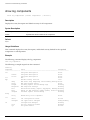
Contents
Preface
Chapter 1
Command Reference Overview
Chapter 2
Commands for Accessing the Switch
clear session
32
configure account
33
configure banner
34
configure cli max-sessions
35
configure cli max-failed-logins
36
configure dns-client add
37
configure dns-client add domain-suffix
38
configure dns-client add name-server
39
configure dns-client default-domain
40
configure dns-client delete domain-suffix
41
configure dns-client delete name-server
42
configure idletimeout
43
configure time
44
configure timezone
45
create account
49
delete account
51
disable cli space-completion
52
disable clipaging
53
disable idletimeout
54
enable cli space-completion
55
ExtremeWare XOS 10.1 Command Reference Guide
3
Contents
Chapter 3
4
enable clipaging
56
enable idletimeout
57
history
58
ping
59
reboot
60
show banner
61
show dns-client
62
show switch
63
traceroute
65
Commands for Managing the Switch
configure snmp add community
69
configure snmp add trapreceiver
70
configure snmp delete community
71
configure snmp delete trapreceiver
72
configure snmp sysContact
73
configure snmp sysLocation
74
configure snmp sysName
75
configure snmpv3 add access
76
configure snmpv3 add community
78
configure snmpv3 add filter
79
configure snmpv3 add filter-profile
80
configure snmpv3 add group user
81
configure snmpv3 add mib-view
82
configure snmpv3 add notify
84
configure snmpv3 add target-addr
85
configure snmpv3 add target-params
86
configure snmpv3 add user
88
configure snmpv3 add user clone-from
90
configure snmpv3 delete access
91
configure snmpv3 delete community
93
configure snmpv3 delete filter
94
configure snmpv3 delete filter-profile
95
configure snmpv3 delete group user
96
ExtremeWare XOS 10.1 Command Reference Guide
Contents
configure snmpv3 delete mib-view
98
configure snmpv3 delete notify
99
configure snmpv3 delete target-addr
100
configure snmpv3 delete target-params
101
configure snmpv3 delete user
102
configure snmpv3 engine-boots
103
configure snmpv3 engine-id
104
configure sntp-client server
105
configure sntp-client update-interval
106
configure telnet port
107
configure tftp port
108
disable dhcp vlan
109
disable snmp access
110
disable sntp-client
111
disable telnet
112
disable tftp
113
enable dhcp vlan
114
enable snmp access
115
enable sntp-client
116
enable tftp
117
exit
118
logout
119
quit
120
show dhcp-client state
121
show management
122
show odometer
123
show session
125
show snmpv3 access
126
show snmpv3 context
128
show snmpv3 counters
129
show snmpv3 engine-info
130
show snmpv3 filter
131
show snmpv3 filter-profile
132
show snmpv3 group
133
ExtremeWare XOS 10.1 Command Reference Guide
5
Contents
Chapter 4
6
show snmpv3 mib-view
135
show snmpv3 notify
137
show snmpv3 target-addr
138
show snmpv3 extreme-target-addr-ext
139
show snmpv3 target-params
140
show snmpv3 user
141
show sntp-client
143
show vr
144
telnet
145
tftp
146
Commands for Configuring Slots and Ports on a Switch
clear counters edp
151
clear slot
152
configure edp advertisement-interval
153
configure jumbo-frame size
154
configure mirroring add
155
configure mirroring delete
156
configure ports auto off
157
configure ports auto on
158
configure ports display-string
159
configure slot
160
configure sharing add ports
161
configure sharing delete ports
162
disable edp ports
163
disable jumbo-frame ports
164
disable learning port
165
disable mirroring
166
disable port
167
disable sharing
168
disable slot
169
enable edp ports
170
enable jumbo-frame ports
171
enable learning port
172
ExtremeWare XOS 10.1 Command Reference Guide
Contents
Chapter 5
enable mirroring to port
173
enable port
174
enable sharing grouping
175
enable slot
177
failover
178
restart ports
179
run msm-failover
180
show edp
181
show mirroring
183
show ports collisions
184
show ports configuration
185
show ports information
186
show ports packet
188
show ports sharing
189
show slot
190
unconfigure ports display string
191
unconfigure slot
192
VLAN Commands
configure dot1q ethertype
194
configure ports monitor vlan
195
configure protocol add
196
configure protocol delete
197
configure vlan add ports
198
configure vlan delete port
199
configure vlan ipaddress
200
configure vlan name
201
configure vlan protocol
202
configure vlan tag
203
create protocol
204
create vlan
205
delete protocol
207
delete vlan
208
disable loopback-mode vlan
209
ExtremeWare XOS 10.1 Command Reference Guide
7
Contents
Chapter 6
Chapter 7
Chapter 8
8
enable loopback-mode vlan
210
show protocol
211
show vlan
212
unconfigure ports monitor vlan
215
unconfigure vlan ipaddress
216
FDB Commands
clear fdb
218
configure fdb agingtime
219
create fdbentry vlan blackhole
220
create fdbentry vlan ports
221
show fdb
223
QoS Commands
configure diffserv examination code-point qosprofile
227
configure dot1p type
228
configure ports qosprofile
229
configure qosprofile
230
disable diffserv examination ports
231
enable diffserv examination ports
232
show diffserv
233
show dot1p
236
show ports qosmonitor
237
show qosprofile
238
unconfigure diffserv examination
239
Commands for Status Monitoring and Statistics
clear counters
242
clear log
243
clear log counters
244
configure log filter events
245
configure log filter events match
248
configure log target filter
251
configure log target format
253
configure log target match
256
ExtremeWare XOS 10.1 Command Reference Guide
Contents
configure log target severity
258
configure node offline
260
configure node online
261
configure node priority
262
configure sys-health-check interval
263
configure syslog add
264
configure syslog delete
265
create log filter
266
delete log filter
267
disable log debug-mode
268
disable log target
269
disable sys-health-check
270
disable syslog
271
enable log debug-mode
272
enable log target
273
enable sys-health-check
274
enable syslog
275
failover
276
show checkpoint-data
277
show fans
279
show heartbeat process
281
show log
283
show log components
286
show log configuration
289
show log configuration filter
291
show log configuration target
292
show log counters
294
show log events
296
show memory
298
show node
300
show ports rxerrors
302
show ports stats
304
show ports txerrors
306
show powersupplies
308
ExtremeWare XOS 10.1 Command Reference Guide
9
Contents
Chapter 9
10
show process
311
show temperature
315
show version
316
unconfigure log filter
319
unconfigure log target format
320
upload log
322
Security Commands
check policy
327
clear access-list counter
328
configure access-list
329
configure radius server
330
configure radius shared-secret
331
configure radius timeout
332
configure radius-accounting server
333
configure radius-accounting shared-secret
334
configure radius-accounting timeout
335
configure tacacs server
336
configure tacacs shared-secret
337
configure tacacs timeout
338
configure tacacs-accounting server
339
configure tacacs-accounting shared-secret
340
configure tacacs-accounting timeout
341
disable radius
342
disable radius-accounting
343
disable tacacs
344
disable tacacs-accounting
345
disable tacacs-authorization
346
enable radius
347
enable radius-accounting
348
enable tacacs
349
enable tacacs-accounting
350
enable tacacs-authorization
351
refresh policy
352
ExtremeWare XOS 10.1 Command Reference Guide
Contents
Chapter 10
save policy
353
show access-list
354
show access-list counter
355
show policy
356
show radius
357
show radius-accounting
358
show tacacs
359
show tacacs-accounting
360
unconfigure access-list
361
unconfigure radius
362
unconfigure radius-accounting
363
unconfigure tacacs
364
unconfigure tacacs-accounting
365
STP Commands
clear counters stp
370
configure stpd add vlan
371
configure stpd default-encapsulation
373
configure stpd delete vlan
375
configure stpd forwarddelay
376
configure stpd hellotime
377
configure stpd maxage
378
configure stpd mode
379
configure stpd ports cost
380
configure stpd ports link-type
381
configure stpd ports mode
383
configure stpd ports priority
384
configure stpd priority
385
configure stpd tag
386
configure vlan add ports stpd
387
create stpd
389
delete stpd
390
disable stpd
391
disable stpd auto-bind
392
ExtremeWare XOS 10.1 Command Reference Guide
11
Contents
Chapter 11
Chapter 12
12
disable stpd ports
393
disable stpd rapid-root-failover
394
enable stpd
395
enable stpd auto-bind
396
enable stpd ports
398
enable stpd rapid-root-failover
399
show stpd
400
show stpd ports
402
show vlan stpd
404
unconfigure stpd
406
unconfigure stpd ports link-type
407
VRRP Commands
configure vrrp vlan vrid
411
configure vrrp vlan vrid authentication
412
configure vrrp vlan vrid track-iproute
413
configure vrrp vlan vrid track-ping frequency miss
414
configure vrrp vlan vrid track-vlan
415
create vrrp vlan vrid
416
delete vrrp vlan vrid
417
disable vrrp vrid
418
enable vrrp vrid
419
show vrrp
420
show vrrp vlan stats
421
IP Unicast Commands
clear iparp
425
configure bootprelay add
426
configure bootprelay delete
427
configure iparp add
428
configure iparp add proxy
429
configure iparp delete
430
configure iparp delete proxy
431
configure iparp timeout
432
configure iproute add
433
ExtremeWare XOS 10.1 Command Reference Guide
Contents
configure iproute add blackhole
434
configure iproute add blackhole default
435
configure iproute add default
436
configure iproute delete
437
configure iproute delete blackhole
438
configure iproute delete blackhole default
439
configure iproute delete default
440
configure iproute priority
441
configure irdp
443
disable bootp vlan
444
disable bootprelay
445
disable icmp address-mask
446
disable icmp parameter-problem
447
disable icmp port-unreachables
448
disable icmp redirects
449
disable icmp time-exceeded
450
disable icmp timestamp
451
disable icmp unreachables
452
disable icmp useredirects
453
disable ipforwarding
454
disable ip-option loose-source-route
455
disable ip-option record-route
456
disable ip-option record-timestamp
457
disable ip-option strict-source-route
458
disable ip-option router-alert
459
disable irdp
460
enable bootp vlan
461
enable bootprelay
462
enable icmp address-mask
463
enable icmp parameter-problem
464
enable icmp port-unreachables
465
enable icmp redirects
466
enable icmp time-exceeded
467
enable icmp timestamp
468
ExtremeWare XOS 10.1 Command Reference Guide
13
Contents
Chapter 13
14
enable icmp unreachables
469
enable icmp useredirects
470
enable ipforwarding
471
enable ip-option loose-source-route
472
enable ip-option record-route
473
enable ip-option record-timestamp
474
enable ip-option strict-source-route
475
enable ip-option router-alert
476
enable iproute sharing
477
enable irdp
478
rtlookup
479
show bootprelay
480
show iparp
482
show iparp proxy
483
show ipconfig
484
show iproute
485
show iproute origin
486
show ipstats
487
unconfigure icmp
490
unconfigure iparp
491
unconfigure irdp
492
IGP Commands
clear ospf counters
495
clear rip counters
496
configure ospf cost
497
configure ospf priority
498
configure ospf authentication
499
configure ospf add virtual-link
500
configure ospf add vlan area
501
configure ospf add vlan area link-type
502
configure ospf area external-filter
503
configure ospf area interarea-filter
504
configure ospf area add range
505
ExtremeWare XOS 10.1 Command Reference Guide
Contents
configure ospf area delete range
506
configure ospf area normal
507
configure ospf area nssa stub-default-cost
508
configure ospf area stub stub-default-cost
509
configure ospf area timer
510
configure ospf ase-limit
511
configure ospf ase-summary add
512
configure ospf ase-summary delete
513
configure ospf delete virtual-link
514
configure ospf delete vlan
515
configure ospf import-policy
516
configure ospf lsa-batch-interval
517
configure ospf metric-table
518
configure ospf routerid
519
configure ospf spf-hold-time
520
configure ospf virtual-link timer
521
configure ospf vlan area
522
configure ospf vlan neighbor add
523
configure ospf vlan neighbor delete
524
configure ospf vlan timer
525
configure rip add vlan
527
configure rip delete vlan
528
configure rip garbagetime
529
configure rip import-policy
530
configure rip routetimeout
531
configure rip vlan rxmode
532
configure rip vlan txmode
533
configure rip updatetime
534
configure rip vlan cost
535
configure rip vlan route-policy
536
configure rip vlan trusted-gateway
537
create ospf area
538
delete ospf area
539
disable ospf
540
ExtremeWare XOS 10.1 Command Reference Guide
15
Contents
16
disable ospf capability opaque-lsa
541
disable ospf export
542
disable ospf originate-default
543
disable ospf use-ip-router-alert
544
disable rip
545
disable rip aggregation
546
disable rip export
547
disable rip originate-default
548
disable rip poisonreverse
549
disable rip splithorizon
550
disable rip triggerupdate
551
disable rip use-ip-router-alert
552
enable ospf
553
enable ospf capability opaque-lsa
554
enable ospf export
555
enable ospf originate-default
556
enable ospf use-ip-router-alert
557
enable rip
558
enable rip aggregation
559
enable rip export
560
enable rip originate-default cost
561
enable rip poisonreverse
562
enable rip splithorizon
563
enable rip triggerupdate
564
enable rip use-ip-router-alert
565
show ospf
566
show ospf area
567
show ospf area detail
568
show ospf ase-summary
569
show ospf interfaces detail
570
show ospf interfaces
571
show ospf lsdb
572
show ospf memory
573
show ospf neighbor
574
ExtremeWare XOS 10.1 Command Reference Guide
Contents
Chapter 14
show ospf virtual-link
575
show rip
576
show rip interface
577
show rip interface vlan
579
show rip memory
580
show rip routes
581
unconfigure ospf
582
unconfigure rip
583
BGP Commands
clear bgp neighbor counters
587
clear bgp flap-statistics
588
configure bgp add aggregate-address
589
configure bgp add confederation-peer sub-AS-number
590
configure bgp add network
591
configure bgp AS-number
592
configure bgp cluster-id
593
configure bgp confederation-id
594
configure bgp delete aggregate-address
595
configure bgp delete confederation-peer sub-AS-number
596
configure bgp delete network
597
configure bgp export shutdown-priority
598
configure bgp import-policy
599
configure bgp local-preference
600
configure bgp med
601
configure bgp neighbor dampening
602
configure bgp neighbor maximum-prefix
604
configure bgp neighbor next-hop-self
606
configure bgp neighbor no-dampening
607
configure bgp neighbor password
608
configure bgp neighbor peer-group
609
configure bgp neighbor route-policy
610
configure bgp neighbor route-reflector-client
611
configure bgp neighbor send-community
612
ExtremeWare XOS 10.1 Command Reference Guide
17
Contents
18
configure bgp neighbor shutdown-priority
613
configure bgp neighbor soft-reset
614
configure bgp neighbor source-interface
615
configure bgp neighbor timer
616
configure bgp neighbor weight
617
configure bgp peer-group dampening
618
configure bgp peer-group maximum-prefix
620
configure bgp peer-group next-hop-self
621
configure bgp peer-group no-dampening
622
configure bgp peer-group route-reflector-client
623
configure bgp peer-group send-community
624
configure bgp peer-group password
625
configure bgp peer-group remote-AS-number
626
configure bgp peer-group route-policy
627
configure bgp peer-group soft-reset
628
configure bgp peer-group source-interface
629
configure bgp peer-group timer
630
configure bgp peer-group weight
631
configure bgp routerid
632
configure bgp soft-reconfiguration
633
create bgp neighbor peer-group
634
create bgp neighbor remote-AS-number
635
create bgp peer-group
636
delete bgp neighbor
637
delete bgp peer-group
638
disable bgp
639
disable bgp aggregation
640
disable bgp always-compare-med
641
disable bgp community format
642
disable bgp export
643
disable bgp neighbor
644
disable bgp neighbor capability
645
disable bgp neighbor remove-private-AS-numbers
646
disable bgp neighbor soft-in-reset
647
ExtremeWare XOS 10.1 Command Reference Guide
Contents
Chapter 15
disable bgp neighbor use-ip-router-alert
648
disable bgp peer-group
649
disable bgp peer-group capability
650
disable bgp peer-group remove-private-AS-numbers
651
disable bgp peer-group soft-in-reset
652
disable bgp peer-group use-ip-router-alert
653
enable bgp
654
enable bgp aggregation
655
enable bgp always-compare-med
656
enable bgp community format
657
enable bgp export
658
enable bgp neighbor
660
enable bgp neighbor capability
661
enable bgp neighbor remove-private-AS-numbers
662
enable bgp neighbor soft-in-reset
663
enable bgp neighbor use-ip-router-alert
664
enable bgp peer-group
665
enable bgp peer-group capability
666
enable bgp peer-group remove-private-AS-numbers
667
enable bgp peer-group soft-in-reset
668
enable bgp peer-group use-ip-router-alert
669
show bgp
670
show bgp neighbor
671
show bgp neighbor routes
672
show bgp peer-group
674
show bgp routes
675
show bgp routes summary
676
show bgp memory
677
IP Multicast Commands
clear igmp group
681
clear igmp snooping
682
clear pim cache
683
configure igmp
684
ExtremeWare XOS 10.1 Command Reference Guide
19
Contents
20
configure igmp snooping vlan ports add static group
685
configure igmp snooping vlan ports delete static group
686
configure igmp snooping vlan ports add static router
687
configure igmp snooping vlan ports delete static router
688
configure igmp snooping vlan ports filter
689
configure igmp snooping flood-list
691
configure igmp snooping leave-timeout
693
configure igmp snooping timer
694
configure pim add vlan
695
configure pim cbsr
696
configure pim crp static
697
configure pim crp timer
698
configure pim crp vlan
699
configure pim delete vlan
700
configure pim register-rate-limit-interval
701
configure pim register-suppress-interval register-probe-interval
702
configure pim register-checksum-to
703
configure pim spt-threshold
704
configure pim timer vlan
705
configure pim vlan trusted-gateway
706
disable igmp
707
disable igmp snooping
708
disable ipmcforwarding
709
disable pim
710
enable igmp
711
enable igmp snooping
712
enable igmp snooping with-proxy
713
enable ipmcforwarding
714
enable pim
715
show igmp
716
show igmp group
718
show igmp snooping
719
show igmp snooping vlan filter
721
show igmp snooping vlan static
722
ExtremeWare XOS 10.1 Command Reference Guide
Contents
Appendix A
Appendix B
show pim
723
show pim cache
724
unconfigure igmp
725
unconfigure pim
726
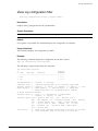
Configuration and Image Commands
download image
728
install image
730
ls
731
mv
732
rm
733
save configuration
734
show running-config
736
unconfigure switch
738
use configuration
739
use image
740
Troubleshooting Commands
disable log debug-mode
742
enable log debug-mode
743
nslookup
744
run diagnostics
745
show diagnostics
747
show tech
749
Index of Commands
ExtremeWare XOS 10.1 Command Reference Guide
21
Contents
22
ExtremeWare XOS 10.1 Command Reference Guide
Preface
This preface provides an overview of this guide, describes guide conventions, and lists other
publications that may be useful.
Introduction
This guide provides the complete syntax for all the commands available in the currently-supported
versions of the ExtremeWare XOSTM software running on modular switches from Extreme Networks®.
This guide is intended for use as a reference by network administrators who are responsible for
installing and setting up network equipment. It assumes knowledge of Extreme Networks switch
configuration. For conceptual information and guidance on configuring Extreme Networks switches, see
the ExtremeWare XOS Concepts Guide for your version of the ExtremeWare XOS software.
Terminology
When features, functionality, or operation is specific to a modular or stand-alone switch family, the
family name is used. Explanations about features and operations that are the same across all product
families simply refer to the product as the “switch.”
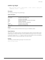
Conventions
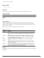
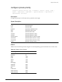
Table 1 and Table 2 list conventions that are used throughout this guide.
Table 1: Notice Icons
Icon
Notice Type
Alerts you to...
Note
Important features or instructions.
Caution
Risk of personal injury, system damage, or loss of data.
ExtremeWare XOS 10.1 Command Reference Guide
23
Preface
Table 1: Notice Icons
Icon
Notice Type
Alerts you to...
Warning
Risk of severe personal injury.
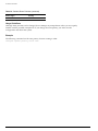
Table 2: Text Conventions
Convention
Description
Screen displays
This typeface indicates command syntax, or represents information as it appears on the
screen.
The words “enter”
and “type”
When you see the word “enter” in this guide, you must type something, and then press
the Return or Enter key. Do not press the Return or Enter key when an instruction
simply says “type.”
[Key] names
Key names are written with brackets, such as [Return] or [Esc].
If you must press two or more keys simultaneously, the key names are linked with a
plus sign (+). Example:
Press [Ctrl]+[Alt]+[Del].
Words in italicized type
Italics emphasize a point or denote new terms at the place where they are defined in
the text.
Command Titles
For clarity and brevity, the command titles omit variables, values, and optional arguments. The
complete command syntax is displayed directly below the command titles.
Related Publications
The publications related to this one are:
• ExtremeWare XOS release notes
• ExtremeWare XOS Concepts Guide
• Extreme Networks BlackDiamond 10K-Series Switch Installation Guide
Documentation for Extreme Networks products is available on the World Wide Web at the following
location:
http://www.extremenetworks.com/
24
ExtremeWare XOS 10.1 Command Reference Guide
1
Command Reference Overview
Introduction
This guide provides details of the command syntax for all ExtremeWare XOS commands as of
ExtremeWare XOS version 10.1.
NOTE
ExtremeWare XOS 10.1 only supports Extreme Networks BlackDiamond® 10800 family of products.
This does not include the other BlackDiamond families, Alpine, Summit “i” series, Summit e-series and
Summit 200 series platforms.
This guide does not provide feature descriptions, explanations of the technologies, or configuration
examples. For information about the various features and technologies supported by Extreme Networks
switches, see the installation and user guides for your product. This guide does not replace the
installation and user guides; this guide supplements the installation and user guides.
Audience
This guide is intended for use by network administrators who are responsible for installing and setting
up network equipment. It assumes a basic working knowledge of the following:
• Local area networks (LANs)
• Ethernet concepts
• Ethernet switching and bridging concepts
• Routing concepts
• Internet Protocol (IP) concepts
• Routing Information Protocol (RIP) and Open Shortest Path First (OSPF) concepts
• Border Gateway Protocol (BGP-4) concepts
• IP Multicast concepts
• Distance Vector Multicast Routing Protocol (DVMRP) concepts
• Protocol Independent Multicast (PIM) concepts
• Internet Packet Exchange (IPX) concepts
ExtremeWare XOS 10.1 Command Reference Guide
25
Command Reference Overview
• Server Load Balancing (SLB) concepts
• Simple Network Management Protocol (SNMP)
This guide also assumes that you have read the Installation and User Guide for your product.
Structure of this Guide
This guide documents each ExtremeWare XOS command. Related commands are grouped together and
organized into chapters based on their most common usage. The chapters reflect the organization of the
ExtremeWare XOS Concepts Guide. If a specific command is relevant to a wide variety of functions and
could be included in a number of different chapters, we have attempted to place the command in the
most logical chapter. Within each chapter, commands appear in alphabetical order. You can use the
Index of Commands to locate specific commands if they do not appear where you expect to find them.
For each command, the following information is provided:
• Command Syntax—The actual syntax of the command. The syntax conventions (the use of braces or
curly brackets, for example) are defined in the section “Understanding the Command Syntax” on
page 27.
• Description—A brief (one sentence) summary of what the command does.
• Syntax Description—The definition of any keywords and options used in the command.
• Default—The defaults, if any, for this command. The default can be the default action of the
command if optional arguments are not provided, or it can be the default state of the switch (such as
for an enable/disable command).
• Usage Guidelines—Information to help you use the command. This may include prerequisites,
prohibitions, and related commands, as well as other information.
• Example—Examples of the command usage, including output, if relevant.
26
ExtremeWare XOS 10.1 Command Reference Guide
Understanding the Command Syntax
Understanding the Command Syntax
When entering a command at the prompt, ensure that you have the appropriate privilege level. Most
configuration commands require you to have the administrator privilege level.
You may see a variety of symbols shown as part of the command syntax. These symbols explain how to
enter the command, and you do not type them as part of the command itself. Table 3 summarizes
command syntax symbols.
Table 3: Command Syntax Symbols
Symbol
Description
angle brackets < >
Enclose a variable or value. You must specify the variable or value. For
example, in the syntax
configure vlan <vlan_name> ipaddress <ip_address>
you must supply a VLAN name for <vlan_name> and an address for
<ip_address> when entering the command. Do not type the angle
brackets. You may not include spaces within angle brackets.
square brackets [ ]
Enclose a required value or list of required arguments. One or more
values or arguments can be specified. For example, in the syntax
use image [primary | secondary]
you must specify either the primary or secondary image when entering
the command. Do not type the square brackets.
vertical bar |
Separates mutually exclusive items in a list, one of which must be
entered. For example, in the syntax
configure snmp community [read-only | read-write]
<string>
you must specify either the read or write community string in the
command. Do not type the vertical bar.
braces { }
Enclose an optional value or a list of optional arguments. One or more
values or arguments can be specified. For example, in the syntax
reboot {<date> <time> | cancel}
you can specify either a particular date and time combination, or the
keyword cancel to cancel a previously scheduled reboot. If you do not
specify an argument, the command will prompt asking if you want to
reboot the switch now. Do not type the braces.
Command Completion with Syntax Helper
The CLI has a built-in syntax helper. If you are unsure of the complete syntax for a particular command,
enter as much of the command as possible and press [Tab]. The syntax helper provides a list of options
for the remainder of the command, and places the cursor at the end of the command you have entered
so far, ready for the next option.
If the command is one where the next option is a named component, such as a VLAN, access profile, or
route map, the syntax helper will also list any currently configured names that might be used as the
next option. In situations where this list might be very long, the syntax helper will list only one line of
names, followed by an ellipses to indicate that there are more names than can be displayed.
The syntax helper also provides assistance if you have entered an incorrect command.
ExtremeWare XOS 10.1 Command Reference Guide
27
Command Reference Overview
Abbreviated Syntax
Abbreviated syntax is the shortest unambiguous allowable abbreviation of a command or parameter.
Typically, this is the first three letters of the command. If you do not enter enough letters to allow the
switch to determine which command you mean, the syntax helper will provide a list of the options
based on the portion of the command you have entered.
NOTE
When using abbreviated syntax, you must enter enough characters to make the command
unambiguous and distinguishable to the switch.
Names
All named components within a category of the switch configuration, such as VLAN, must have a
unique name. Names can be re-used across categories, however. Names must begin with an alphabetical
character and cannot contain any spaces. The maximum length for a name is 32 characters. Names may
contain alphanumeric characters and underscores (_) and cannot be keywords, such as vlan, stp, and so
on.
Command Shortcuts
All named components within a category of the switch configuration must have a unique name.
Components are named using the create command. When you enter a command to configure a named
component, you do not need to use the keyword of the component. For example, to create a VLAN, you
must enter a unique VLAN name:
create vlan engineering
Once you have created the VLAN with a unique name, you can then eliminate the keyword vlan from
all other commands that require the name to be entered. For example, instead of entering the modular
switch command
configure vlan engineering delete port 1:3,4:6
you could enter the following shortcut:
configure engineering delete port 1:3,4:6
Similarly, on the stand-alone switch, instead of entering the command
configure vlan engineering delete port 1-3,6
you could enter the following shortcut:
configure engineering delete port 1-3,6
Modular Switch Numerical Ranges
Commands that require you to enter one or more port numbers on a modular switch use the parameter
<portlist> in the syntax. A <portlist> can be one port on a particular slot. The syntax for the port
and slot is:
port <slot_number>:<port_number>
For example, port 1 on slot 3 would be:
28
ExtremeWare XOS 10.1 Command Reference Guide
Line-Editing Keys
port 3:1
A <portlist> can be a range of numbers. For example, ports 1 through 3 on slot 3 would be:
port 3:1-3:3
You can add additional slot and port numbers to the list, separated by a comma:
port 3:1,4:8,6:10
You can specify all ports on a particular slot, using the asterisk (*) wildcard. For example,
port 3:*
indicates all ports on slot 3.
You can specify a range of slots and ports. For example,
port 2:3-4:5
indicates slot 2, port 3 through slot 4, port 5.
Line-Editing Keys
Table 4 describes the line-editing keys available using the CLI.
Table 4: Line-Editing Keys
Key(s)
Description
Left arrow or [Ctrl] + Moves the cursor one character to the left.
B
Right arrow or [Ctrl]
+F
Moves the cursor one character to the right.
[Ctrl] + H or
Backspace
Deletes character to left of cursor and shifts remainder of line to left.
Delete or [Ctrl] + D
Deletes character under cursor and shifts remainder of line to left.
[Ctrl] + K
Deletes characters from under cursor to end of line.
Insert
Toggles on and off. When toggled on, inserts text and shifts previous
text to right.
Left Arrow
Moves cursor to left.
Right Arrow
Moves cursor to right.
Home or [Ctrl] + A
Moves cursor to first character in line.
End or [Ctrl] + E
Moves cursor to last character in line.
[Ctrl] + L
Clears screen and movers cursor to beginning of line.
[Ctrl] + P or
Up Arrow
Displays previous command in command history buffer and places cursor
at end of command.
[Ctrl] + N or
Down Arrow
Displays next command in command history buffer and places cursor at
end of command.
[Ctrl] + U
Clears all characters typed from cursor to beginning of line.
[Ctrl] + W
Deletes previous word.
[Ctrl] + C
Interrupts the current CLI command execution.
ExtremeWare XOS 10.1 Command Reference Guide
29
Command Reference Overview
Command History
ExtremeWare XOS “remembers” all the commands you enter. You can display a list of these commands
by using the following command:
history
If you use a command more than once, consecutively, the history will only list the first instance.
30
ExtremeWare XOS 10.1 Command Reference Guide
2
Commands for Accessing the Switch
This chapter describes:
• Commands used for accessing and configuring the switch including how to set up user accounts,
passwords, date and time settings, and software licenses
• Commands used for configuring the Domain Name Service (DNS) client
• Commands used for checking basic switch connectivity
ExtremeWare XOS supports the following two levels of management:
• User
• Administrator
A user-level account has viewing access to all manageable parameters, with the exception of:
• User account database
• SNMP community strings
A user-level account can use the
command to test device reachability and change the password assigned to the account name.
An administrator-level account can view and change all switch parameters. It can also add and delete
users and change the password associated with any account name. The administrator can disconnect a
management session that has been established by way of a Telnet connection. If this happens, the user
logged on by way of the Telnet connection is notified that the session has been terminated.
The DNS client in ExtremeWare XOS augments certain ExtremeWare XOS commands to accept either IP
addresses or host names. For example, DNS can be used during a Telnet session when you are accessing
a device or when using the ping command to check the connectivity of a device.
The switch offers the following commands for checking basic connectivity:
•
ping
•
traceroute
The ping command enables you to send Internet Control Message Protocol (ICMP) echo messages to a
remote IP device. The traceroute command enables you to trace the routed path between the switch
and a destination endstation.
ExtremeWare XOS 10.1 Command Reference Guide
31
Commands for Accessing the Switch
clear session
clear session <sessId> | all
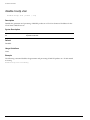
Description
Terminates a Telnet session from the switch.
Syntax Description
sessId
Specifies a session number from show session output to terminate.
Default
N/A.
Usage Guidelines
An administrator-level account can disconnect a management session that has been established by way
of a Telnet connection. You can determine the session number of the session you want to terminate by
using the show session command. The show session output displays information about current
Telnet sessions including:
• The session number
• The login date and time
• The user name
• The type of Telnet session
Depending on the software version running on your switch, additional session information may be
displayed. The session number is the first number displayed in the show session output.
Example
The following command terminates session 4 from the system:
clear session 4
32
ExtremeWare XOS 10.1 Command Reference Guide
configure account
configure account
configure account <name> {password}
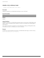
Description
Configures a user account password.
Syntax Description
name
Specifies a user account name.
password
Specifies a user password. See “Usage Guidelines” for more information.
Default
N/A.
Usage Guidelines
You must create a user account before you can configure a user account. Use the create account
command to create a user account.
You must have administrator privileges to change passwords for accounts other than your own. User
names and passwords are case-sensitive.
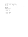
Example
The following command defines a new password for the account admin:
configure account admin
The switch responds with a password prompt:
password:
Your keystrokes will not be echoed as you enter the new password. After you enter the password, the
switch will then prompt you to reenter it.
Reenter password:
Assuming you enter it successfully a second time, the password is now changed.
In ExtremeWare XOS, the following command defines a new password, Extreme1, for the account admin:
configure account admin Extreme1
ExtremeWare XOS 10.1 Command Reference Guide
33
Commands for Accessing the Switch
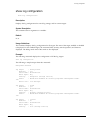
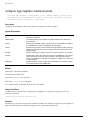
configure banner
configure banner
Description
Configures the banner string that is displayed at the beginning of each login prompt of each session.
Syntax Description
This command has no arguments or variables.
Default
N/A.
Usage Guidelines
Press [Return] at the beginning of a line to terminate the command and apply the banner. To clear the
banner, press [Return] at the beginning of the first line.
You can enter up to 24 rows of 79-column text that is displayed before the login prompt of each session.
Example
The following command adds a banner, Welcome to the switch, before the login prompt:
configure banner [Return]
Welcome to the switch
34
ExtremeWare XOS 10.1 Command Reference Guide
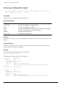
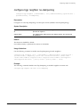
configure cli max-sessions
configure cli max-sessions
configure cli max-sessions <num-of-sessions>
Description
Limits number of simultaneous CLI sessions on the switch.
Syntax Description
num-of-sessions
Specifies the maximum number of concurrent sessions permitted.
Default
The default is eight sessions.
Usage Guidelines
The value must be greater than 0.
Example
configure cli max-sessions 10
ExtremeWare XOS 10.1 Command Reference Guide
35
Commands for Accessing the Switch
configure cli max-failed-logins
configure cli max-failed-logins <num-of-logins>
Description
Establishes the maximum number of failed logins permitted before the session is terminated.
Syntax Description
num-of-logins
Specifies the maximum number of failed logins permitted.
Default
The default is three logins.
Usage Guidelines
The value must be greater than 0.
Example
The following command sets the maximum number of failed logins to five:
configure cli max-failed-logins 5
36
ExtremeWare XOS 10.1 Command Reference Guide
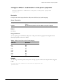
configure dns-client add
configure dns-client add
configure dns-client add domain-suffix <domain_name> | name-server
<ip_address>
Description
Adds a DNS name server to the available server list for the DNS client.
Syntax Description
ip_address
Specifies an IP address.
domain_name
Specifies a domain name.
Default
N/A.
Usage Guidelines
Up to eight DNS name servers can be configured.
Example
The following command specifies that the switch use the DNS server 10.1.2.1:
configure dns-client add 10.1.2.1
ExtremeWare XOS 10.1 Command Reference Guide
37
Commands for Accessing the Switch
configure dns-client add domain-suffix
configure dns-client add domain-suffix <domain_name>
Description
Adds a domain name to the domain suffix list.
Syntax Description
domain_name
Specifies a domain name.
Default
N/A.
Usage Guidelines
The domain suffix list can include up to six items. If the use of all previous names fails to resolve a
name, the most recently added entry on the domain suffix list will be the last name used during name
resolution. This command will not overwrite any exiting entries. If a null string is used as the last suffix
in the list, and all other lookups fail, the name resolver will attempt to look up the name with no suffix.
Example
The following command configures a domain name and adds it to the domain suffix list:
configure dns-client add domain-suffix xyz_inc.com
38
ExtremeWare XOS 10.1 Command Reference Guide
configure dns-client add name-server
configure dns-client add name-server
configure dns-client add name-server <ip_address>
Description
Adds a DNS name server to the available server list for the DNS client.
Syntax Description
ip_address
Specifies an IP address.
Default
N/A.
Usage Guidelines
Up to eight DNS name servers can be configured.
Example
The following command specifies that the switch use the DNS server 10.1.2.1:
configure dns-client add name-server 10.1.2.1
ExtremeWare XOS 10.1 Command Reference Guide
39
Commands for Accessing the Switch
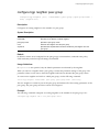
configure dns-client default-domain
configure dns-client default-domain <domain_name>
Description
Configures the domain that the DNS client uses if a fully qualified domain name is not entered.
Syntax Description
domain_name
Specifies a default domain name.
Default
N/A.
Usage Guidelines
Sets the DNS client default domain name to domain_name. The default domain name will be used to
create a fully qualified host name when a domain name is not specified. For example, if the default
default domain name is set to “food.com” then when a command like “ping dog” is entered, the ping
will actually be executed as “ping dog.food.com”.
Example
The following command configures the default domain name for the server:
configure dns-client default-domain xyz_inc.com
40
ExtremeWare XOS 10.1 Command Reference Guide
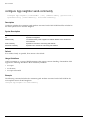
configure dns-client delete domain-suffix
configure dns-client delete domain-suffix
configure dns-client delete domain-suffix <domain_name>
Description
Deletes a domain name from the domain suffix list.
Syntax Description
domain_name
Specifies a domain name.
Default
N/A.
Usage Guidelines
This command randomly removes an entry from the domain suffix list. If the deleted item was not the
last entry in the list, all items that had been added later are moved up in the list. If no entries in the list
match the domain name specified, an error message will be displayed.
Example
The following command deletes a domain name from the domain suffix list:
configure dns-client delete domain-suffix xyz_inc.com
ExtremeWare XOS 10.1 Command Reference Guide
41
Commands for Accessing the Switch
configure dns-client delete name-server
configure dns-client delete name-server <ipaddress>
Description
Removes a DNS name server from the available server list for the DNS client.
Syntax Description
ipaddress
Specifies an IP address.
Default
N/A.
Usage Guidelines
None.
Example
The following command removes a DNS server from the list:
configure dns-client delete name-server 10.1.2.1
42
ExtremeWare XOS 10.1 Command Reference Guide
configure idletimeout
configure idletimeout
configure idletimeout <minutes>
Description
Configures the time-out for idle console and Telnet sessions.
Syntax Description
minutes
Specifies the time-out interval, in minutes. Range is 1 to 240 (1 minute to 4
hours).
Default
The default time-out is 20 minutes.
Usage Guidelines
This command configures the length of time the switch will wait before disconnecting idle console or
Telnet sessions. The idletimeout feature must be enabled for this command to have an effect (the
idletimeout feature is disabled by default).
Example
The following command sets the time-out for idle login and console sessions to 10 minutes:
configure idletimeout 10
ExtremeWare XOS 10.1 Command Reference Guide
43
Commands for Accessing the Switch
configure time
configure time <month> <day> <year> <hour> <min> <sec>
Description
Configures the system date and time.
Syntax Description
month
Specifies the month. The range is 1-12.
day
Specifies the day of the month. The range is 1-31.
year
Specifies the year in the YYYY format.
hour
Specifies the hour of the day. The range is 0 (midnight) to 23 (11 pm).
min
Specifies the minute. The range is 0-59.
sec
Specifies the second. The range is 0-59.
Default
N/A.
Usage Guidelines
The format for the system date and time is as follows:
mm dd yyyy hh mm ss
The time uses a 24-hour clock format. You cannot set the year past 2036. You have the choice of
inputting the entire time/date string. If you provide one item at a time and press [Tab], the screen
prompts you for the next item. Press <cr> to complete the input.
Example
The following command configures a system date of February 15, 2002 and a system time of 8:42 AM
and 55 seconds:
configure time 02 15 2002 08 42 55
44
ExtremeWare XOS 10.1 Command Reference Guide
configure timezone
configure timezone
configure timezone {name <tz_name>} <GMT_offset>
{autodst {name <dst_timezone_ID>} {<dst_offset>}
{begins [every <floatingday> | on <absoluteday>] {at <time_of_day>}
{ends [every <floatingday> | on <absoluteday>] {at <time_of_day>}}}
| noautodst}
Description
Configures the Greenwich Mean Time (GMT) offset and Daylight Saving Time (DST) preference.
Syntax Description
GMT_offset
Specifies a Greenwich Mean Time (GMT) offset, in + or - minutes.
std-timezone-ID
Specifies an optional name for this timezone specification. May be up to six
characters in length. The default is an empty string.
autodst
Enables automatic Daylight Saving Time.
dst-timezone-ID
Specifies an optional name for this DST specification. May be up to six
characters in length. The default is an empty string.
dst_offset
Specifies an offset from standard time, in minutes. Value is in the range of 1
to 60. Default is 60 minutes.
floating_day
Specifies the day, week, and month of the year to begin or end DST each
year. Format is:
<week><day><month> where:
•
<week> is specified as [first | second | third | fourth | last] or 1-5.
•
<day> is specified as [sunday | monday | tuesday | wednesday | thursday |
friday | saturday] or 1-7 (where 1 is Sunday).
•
<month> is specified as [january | february | march | april | may | june | july
| august | september | october | november | december] or 1-12.
Default for beginning is first sunday april; default for ending is last sunday
october.
absolute_day
Specifies a specific day of a specific year on which to begin or end DST.
Format is:
<month>/<day>/<year> where:
•
<month> is specified as 1-12.
•
<day> is specified as 1-31.
•
<year> is specified as 1970-2035.
The year must be the same for the begin and end dates.
time_of_day
Specifies the time of day to begin or end Daylight Saving Time. May be
specified as an hour (0-23) or as hour:minutes. Default is 2:00.
noautodst
Disables automatic Daylight Saving Time.
Default
Autodst, beginning every first Sunday in April, and ending every last Sunday in October.
ExtremeWare XOS 10.1 Command Reference Guide
45
Commands for Accessing the Switch
Usage Guidelines
Network Time Protocol (NTP) server updates are distributed using GMT time. To properly display the
local time in logs and other timestamp information, the switch should be configured with the
appropriate offset to GMT based on geographic location.
The gmt_offset is specified in +/- minutes from the GMT time.
Automatic DST changes can be enabled or disabled. The default configuration, where DST begins on the
first Sunday in April at 2:00 AM and ends the last Sunday in October at 2:00 AM, applies to most of
North America, and can be configured with the following syntax:
configure timezone <gmt_offst> autodst.
The starting and ending date and time for DST may be specified, as these vary in time zones around the
world.
• Use the every keyword to specify a year-after-year repeating set of dates (for example, the last
Sunday in March every year)
• Use the on keyword to specify a non-repeating, specific date for the specified year. If you use this
option, you will need to specify the command again every year.
• The begins specification defaults to every first sunday april.
• The ends specification defaults to every last sunday october.
• The ends date may occur earlier in the year than the begins date. This will be the case for countries
in the Southern Hemisphere.
• If you specify only the starting or ending time (not both) the one you leave unspecified will be reset
to its default.
• The time_of_day specification defaults to 2:00.
• The timezone IDs are optional. They are used only in the display of timezone configuration
information in the show switch command.
To disable automatic DST changes, re-specify the GMT offset using the noautodst option:
configure timezone <gmt_offst> noautodst.
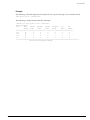
NTP updates are distributed using GMT time. To properly display the local time in logs and other
timestamp information, the switch should be configured with the appropriate offset to GMT based on
geographical location. Table 5 describes the GMT offsets.
Table 5: Greenwich Mean Time Offsets
GMT Offset GMT Offset
in Hours
in Minutes Common Time Zone References
+0:00
+0
GMT - Greenwich Mean
UT or UTC - Universal (Coordinated)
Cities
London, England; Dublin, Ireland;
Edinburgh, Scotland; Lisbon, Portugal;
Reykjavik, Iceland; Casablanca, Morocco
WET - Western European
-1:00
-60
WAT - West Africa
Cape Verde Islands
-2:00
-120
AT - Azores
Azores
-3:00
-180
-4:00
-240
46
Brasilia, Brazil; Buenos Aires, Argentina;
Georgetown, Guyana;
AST - Atlantic Standard
Caracas; La Paz
ExtremeWare XOS 10.1 Command Reference Guide
configure timezone
Table 5: Greenwich Mean Time Offsets (continued)
GMT Offset GMT Offset
in Hours
in Minutes Common Time Zone References
Cities
-5:00
-300
EST - Eastern Standard
Bogota, Columbia; Lima, Peru; New York,
NY, Trevor City, MI USA
-6:00
-360
CST - Central Standard
Mexico City, Mexico
-7:00
-420
MST - Mountain Standard
Saskatchewan, Canada
-8:00
-480
PST - Pacific Standard
Los Angeles, CA, Cupertino, CA, Seattle,
WA USA
-9:00
-540
YST - Yukon Standard
-10:00
-600
AHST - Alaska-Hawaii Standard
CAT - Central Alaska
HST - Hawaii Standard
-11:00
-660
NT - Nome
-12:00
-720
IDLW - International Date Line West
+1:00
+60
CET - Central European
FWT - French Winter
MET - Middle European
MEWT - Middle European Winter
Paris, France; Berlin, Germany;
Amsterdam, The Netherlands; Brussels,
Belgium; Vienna, Austria; Madrid, Spain;
Rome, Italy; Bern, Switzerland; Stockholm,
Sweden; Oslo, Norway
SWT - Swedish Winter
+2:00
+120
EET - Eastern European, Russia Zone 1 Athens, Greece; Helsinki, Finland;
Istanbul, Turkey; Jerusalem, Israel; Harare,
Zimbabwe
+3:00
+180
BT - Baghdad, Russia Zone 2
Kuwait; Nairobi, Kenya; Riyadh, Saudi
Arabia; Moscow, Russia; Tehran, Iran
+4:00
+240
ZP4 - Russia Zone 3
Abu Dhabi, UAE; Muscat; Tblisi;
Volgograd; Kabul
+5:00
+300
ZP5 - Russia Zone 4
+5:30
+330
IST – India Standard Time
+6:00
+360
ZP6 - Russia Zone 5
+7:00
+420
WAST - West Australian Standard
+8:00
+480
CCT - China Coast, Russia Zone 7
+9:00
+540
JST - Japan Standard, Russia Zone 8
+10:00
+600
EAST - East Australian Standard
New Delhi, Pune, Allahabad, India
GST - Guam Standard
Russia Zone 9
+11:00
+660
+12:00
+720
IDLE - International Date Line East
NZST - New Zealand Standard
Wellington, New Zealand; Fiji, Marshall
Islands
NZT - New Zealand
ExtremeWare XOS 10.1 Command Reference Guide
47
Commands for Accessing the Switch
Example
The following command configures GMT offset for Mexico City, Mexico and disables automatic DST:
configure timezone -360 noautodst
The following four commands are equivalent, and configure the GMT offset and automatic DST
adjustment for the US Eastern timezone, with an optional timezone ID of EST:
configure timezone name EST -300 autodst name EDT 60 begins every first sunday april
at 2:00 ends every last sunday october at 2:00
configure timezone name EST -300 autodst name EDT 60 begins every 1 1 4 at 2:00 ends
every 5 1 10 at 2:00
configure timezone name EST -300 autodst name EDT
configure timezone -300 autodst
The following command configures the GMT offset and automatic DST adjustment for the Middle
European timezone, with the optional timezone ID of MET:
configure timezone name MET 60 autodst name MDT begins every last sunday march at 1
ends every last sunday october at 1
The following command configures the GMT offset and automatic DST adjustment for New Zealand.
The ending date must be configured each year because it occurs on the first Sunday on or after March 5:
configure timezone name NZST 720 autodst name NZDT 60 begins every first sunday
october at 2 ends on 3/16/2002 at 2
48
ExtremeWare XOS 10.1 Command Reference Guide
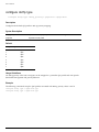
create account
create account
create account [admin | user] <account-name> {<password>}
Description
Creates a new user account.
Syntax Description
admin
Specifies an access level for account type admin.
user
Specifies an access level for account type user.
account-name
Specifies a new user account name. See “Usage Guidelines” for more
information.
password
Specifies a user password. See “Usage Guidelines” for more information.
Default
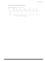
By default, the switch is configured with two accounts with the access levels shown in Table 6.
Table 6: User Account Levels
Account Name
Access Level
admin
This user can access and change all manageable parameters. The admin account
cannot be deleted.
user
This user can view (but not change) all manageable parameters, with the following
exceptions:
•
This user cannot view the user account database.
•
This user cannot view the SNMP community strings.
This user has access to the ping command.
You can use the default names (admin and user), or you can create new names and passwords for the
accounts. Default accounts do not have passwords assigned to them.
Usage Guidelines
The switch can have a total of 16 user accounts. The system must have one administrator account.
You must have administrator privileges to change passwords for accounts other than your own. User
names and passwords are case-sensitive. User account names must have a minimum of 1 character and
can have a maximum of 30 characters. Passwords must have a minimum of 0 characters and can have a
maximum of 16 characters.
The encrypted option should only be used by the switch to generate an ASCII configuration (using the
upload configuration command), and parsing a switch-generated configuration (using the download
configuration command).
Example
The following command creates a new account named John2 with administrator privileges:
ExtremeWare XOS 10.1 Command Reference Guide
49
Commands for Accessing the Switch
create account admin john2
50
ExtremeWare XOS 10.1 Command Reference Guide
delete account
delete account
delete account <name>
Description
Deletes a specified user account.
Syntax Description
name
Specifies a user account name.
Default
N/A.
Usage Guidelines
Use the show accounts command to determine which account you want to delete from the system. The
show accounts output displays the following information in a tabular format:
• The user name
• Access information associated with each user
• User login information
• Session information
Depending on the software version running on your switch and the type of switch you have, additional
account information may be displayed.
You must have administrator privileges to delete a user account. The system must have one
administrator account; the command will fail if an attempt is made to delete the last administrator
account on the system.
Do not delete the default administrator account. If you do, it is automatically restored, with no
password, the next time you download a configuration. To ensure security, change the password on the
default account, but do not delete it. The changed password will remain intact through configuration
uploads and downloads.
If you must delete the default account, first create another administrator-level account. Remember to
manually delete the default account again every time you download a configuration.
Example
The following command deletes account John2:
delete account john2
ExtremeWare XOS 10.1 Command Reference Guide
51
Commands for Accessing the Switch
disable cli space-completion
disable cli space-completion
Description
Disables the XOS feature that completes a command automatically with the spacebar. If you disable this
feature, The [Tab] key can still be used for auto-completion.
Syntax Description
This command has no arguments or variables.
Default
Disabled.
Usage Guidelines
None.
Example
disable cli space-completion
52
ExtremeWare XOS 10.1 Command Reference Guide
disable clipaging
disable clipaging
disable clipaging
Description
Disables pausing at the end of each show screen.
Syntax Description
This command has no arguments or variables.
Default
Enabled.
Usage Guidelines
The command line interface (CLI) is designed for use in a VT100 environment. Most show command
output will pause when the display reaches the end of a page. This command disables the pause
mechanism and allows the display to print continuously to the screen.
CLI paging is only active on a per-shell session basis. In other words, when you enable or disable CLI
paging from within the current configuration, it only affects that session. For new or existing sessions,
paging is enabled by default. This setting cannot be saved.
Example
The follow command disables clipaging and allows you to print continuously to the screen:
disable clipaging
ExtremeWare XOS 10.1 Command Reference Guide
53
Commands for Accessing the Switch
disable idletimeout
disable idletimeout
Description
Disables the timer that disconnects idle sessions from the switch.
Syntax Description
This command has no arguments or variables.
Default
Enabled. Timeout 20 minutes.
Usage Guidelines
When idle time-outs are disabled, console sessions remain open until the switch is rebooted or you
logoff. Telnet sessions remain open until you close the Telnet client.
To view the status of idle time-outs on the switch, use the show management command. The show
management command displays information about the switch including the enable/disable state for idle
time-outs.
Example
The following command disables the timer that disconnects all sessions to the switch:
disable idletimeout
54
ExtremeWare XOS 10.1 Command Reference Guide
enable cli space-completion
enable cli space-completion
enable cli space-completion
Description
Enables the XOS feature that completes a command automatically with the spacebar. The [Tab] key can
also be used for auto-completion.
Syntax Description
This command has no arguments or variables.
Default
Disabled.
Usage Guidelines
None.
Example
enable cli space-completion
ExtremeWare XOS 10.1 Command Reference Guide
55
Commands for Accessing the Switch
enable clipaging
enable clipaging
Description
Enables the pause mechanism and does not allow the display to print continuously to the screen.
Syntax Description
This command has no arguments or variables.
Default
Enabled.
Usage Guidelines
The command line interface (CLI) is designed for use in a VT100 environment. Most show command
output will pause when the display reaches the end of a page.
If CLI paging is enabled and you use the show tech-support command to diagnose system technical
problems, the CLI paging feature is disabled.
CLI paging is only active on a per-shell session basis. In other words, when you enable or disable CLI
paging from within the current configuration, it only affects that session. For new or existing sessions,
paging is enabled by default. This setting cannot be saved.
Example
The following command enables clipaging and does not allow the display to print continuously to the
screen:
enable clipaging
56
ExtremeWare XOS 10.1 Command Reference Guide
enable idletimeout
enable idletimeout
enable idletimeout
Description
Enables a timer that disconnects Telnet and console sessions after 20 minutes of inactivity.
Syntax Description
cr
Executes the command.
Default
Enabled. Timeout 20 minutes.
Usage Guidelines
You can use this command to ensure that a Telnet or console session is disconnected if it has been idle
for the required length of time. This ensures that there are no hanging connections.
To view the status of idle time-outs on the switch, use the show management command. The show
management command displays information about the switch including the enable/disable state for idle
time-outs. You can configure the length of the time-out interval.
Example
The following command enables a timer that disconnects any Telnet and console sessions after 20
minutes of inactivity:
enable idletimeout
fullL3
ExtremeWare XOS 10.1 Command Reference Guide
57
Commands for Accessing the Switch
history
history
Description
Displays a list of all the commands entered on the switch.
Syntax Description
This command has no arguments or variables.
Default
N/A.
Usage Guidelines
ExtremeWare XOS “remembers” all the commands you entered on the switch. Use the history
command to display a list of these commands.
Example
The following command displays all the commands entered on the switch:
history
If you use a command more than once, consecutively, the history will only list the first instance.
58
ExtremeWare XOS 10.1 Command Reference Guide
ping
ping
ping {udp} {[continuous | count <count>]} {start-size <start-size>}
{end-size <end-size}} {interval <interval>} {ttl <ttl>} {tos <tos>}
{vr <vrid>} <host>
Description
Enables you to send User Datagram Protocol (UDP) or Internet Control Message Protocol (ICMP) echo
messages or to a remote IP device.
Syntax Description
udp
Specifies that the ping request should use UDP instead of ICMP.
continuous
Specifies that UDP or ICMP echo messages to be sent continuously. This
option can be interrupted by pressing any key.
start-size
Specifies the size, in bytes, of the packet to be sent, or the starting size if
incremental packets are to be sent.
end-size
Specifies the end size, in bytes, of the packet to be sent, when incremental
packets are sent.
vr
Specifies the virtual route to use for sending out the echo message. If not
specified, the virtual router assigned to the default VLAN is used.
tos
Sets the TOS value.
ttl
Sets the TTL value.
dont-fragment
Sets the IP to not fragment the bit.
interval
Sets the time interval between sending out ping requests.
host
Specifies a IPV4 host to ping.
Default
N/A.
Usage Guidelines
The ping command is used to test for connectivity to a specific host.
The ping command is available for both the user and administrator privilege level.
If a ping request fails, the switch continues to send ping messages until interrupted. Press any key or
[Ctrl] + C to interrupt a ping request.
Example
The following command enables continuous ICMP echo messages to be sent to a remote host:
ping continuous 123.45.67.8
ExtremeWare XOS 10.1 Command Reference Guide
59
Commands for Accessing the Switch
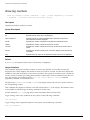
reboot
reboot {time <date> <time> | cancel} {slot <slot number> | msm <slotid>}
Description
Reboots the switch or the module in the specified slot at a specified date and time.
Syntax Description
date
Specifies a reboot date in mm/dd/yyyy format.
time
Specifies a reboot time in hh:mm:ss format.
cancel
Cancels a previously scheduled reboot.
slot number
Specifies the slot where the module is installed.
slotid
Specifies the slot--A or B--in a BlackDiamond MSM module.
Default
N/A.
Usage Guidelines
If you do not specify a reboot time, the switch will reboot immediately following the command, and
any previously scheduled reboots are cancelled. To cancel a previously scheduled reboot, use the
cancel option.
The slot <slot number> option is added to the command to make it possible to reboot a module in a
specific slot. When you specify this option, the command applies to the module in the specified slot,
rather than to the switch. In general, the modules that can be rebooted have separate images from the
ExtremeWare XOS image for the switch.
The modules that can be rebooted are slave or switch fabric MSM modules.
NOTE
When you configure a timed reboot of an MSM, there is no show output in the CLI to view the
configuration.
Example
The following command reboots the switch at 8:00 AM on April 15, 2002:
reboot 04/15/2002 08:00:00
60
ExtremeWare XOS 10.1 Command Reference Guide
show banner
show banner
show banner
Description
Displays the user-configured banner string.
Syntax Description
This command has no arguments or variables.
Default
N/A.
Usage Guidelines
Use this command to view the banner that is displayed before the login prompt.
Example
The following command displays the switch banner:
show banner
Output from this command looks similar to the following:
Extreme Networks Summit48i Layer 3 Switch
#########################################################
Unauthorized Access is strictly prohibited.
Violators will be persecuted
#########################################################
ExtremeWare XOS 10.1 Command Reference Guide
61
Commands for Accessing the Switch
show dns-client
show dns-client
Description
Displays the DNS configuration.
Syntax Description
This command has no arguments or variables.
Default
N/A.
Usage Guidelines
None.
Example
The following command displays the DNS configuration:
show dns-client
Output from this command looks similar to the following:
Number of domain suffixes: 2
Domain Suffix 1:
njudah.local
Domain Suffix 2:
dbackman.com
Number of name servers: 2
Name Server 1: 172.17.1.104
Name Server 2: 172.17.1.123
62
ExtremeWare XOS 10.1 Command Reference Guide
show switch
show switch
show switch {detail}
Description
Displays the current switch information.
Syntax Description
This command has no arguments or variables.
Default
N/A.
Usage Guidelines
Viewing statistics on a regular basis allows you to see how well your network is performing. If you
keep simple daily records, you will see trends emerging and notice problems arising before they cause
major network faults. This way, statistics can help you get the best out of your network.
The show switch command displays:
• sysName, sysLocation, sysContact
• MAC address
• License type
• System mode
• Diagnostics mode (BlackDiamond switch only)
• RED configuration
• DLCS state
• Backplane load sharing (BlackDiamond switch only)
• System health check
• Recovery mode
• Transceiver diagnostics
• FDB-scan diagnostics
• MSM failover information (BlackDiamond switch only)
• Watchdog state
• Reboot loop information
• Current date, time, system boot time, and time zone configuration
• Configuration modified information
• Any scheduled reboot information
• Scheduled upload/download information
• Operating environment (temperature, fans, and power supply status)
• Software image information (primary/secondary image, date/time, version)
ExtremeWare XOS 10.1 Command Reference Guide
63
Commands for Accessing the Switch
• NVRAM configuration information (primary/secondary configuration, date/time, size, version)
• PACE configuration information
• Software licensing information
• MSM information (BlackDiamond switch only)
• Mode of switch operation (Alpine 3802 only)
This information may be useful for your technical support representative if you have a problem.
Depending on the software version running on your switch, additional or different switch information
may be displayed.
Example
The following command displays current switch information:
show switch
Output from this command looks similar to the following:
SysName:
SysLocation:
SysContact:
System MAC:
BD-10808
SysHealth check:
Enabled
Current Time:
Timezone:
Boot Time:
Tue Aug 9 11:37:42 1927
[Auto DST Disabled] GMT Offset: 0 minutes, name is UTC.
Tue Aug 9 11:24:10 1927
MSM:
MSM-B
------------------------
Current State:
MSM-A
-----------------------MASTER
Image Selected:
Image Booted:
Primary version:
Secondary version:
2
2
10.1.0.86
10.1.0.86
0
0
Config Selected:
Config Booted:
primary.cfg
primary.cfg
64
support@extremenetworks.com, +1 888 257 3000
00:01:30:F9:9B:90
ExtremeWare XOS 10.1 Command Reference Guide
traceroute
traceroute
traceroute {vrid <vrid>} <host> {from <source IP address>} {ttl <number>}
{port <port number>}
Description
Enables you to trace the routed path between the switch and a destination endstation.
Syntax Description
vrid
Specifies a virtual router.
host
Specifies the hostname or IP address of the destination endstation.
from <source IP address>
Uses the specified source address in the ICMP packet. If not specified, the
address of the transmitting interface is used.
ttl <number>
Configures the switch to trace up to the time-to-live number of the switch.
port <port number>
Specifies the UDP port number.
Default
N/A.
Usage Guidelines
To use the host name parameter, you must first configure DNS.
Each router along the path is displayed.
Example
The following command enables the traceroute function to a destination of 123.45.67.8:
traceroute 123.45.67.8
ExtremeWare XOS 10.1 Command Reference Guide
65
Commands for Accessing the Switch
66
ExtremeWare XOS 10.1 Command Reference Guide
3
Commands for Managing the Switch
This chapter describes commands for:
• Configuring Simple Network Management Protocol (SNMP) parameters on the switch
• Managing the switch using Telnet
• Transferring files using TFTP
• Configuring Simple Network Time Protocol (SNTP) parameters on the switch
SNMP
Any network manager running the Simple Network Management Protocol (SNMP) can manage the
switch, if the Management Information Base (MIB) is installed correctly on the management station.
Each network manager provides its own user interface to the management facilities.
The following SNMP parameters can be configured on the switch:
• Authorized managers—An authorized manager can be either a single network management station,
or a range of addresses (for example, a complete subnet) specified by a prefix and a mask. The
switch can have a maximum of eight authorized managers.
• Community strings—The community strings allow a simple method of authentication between the
switch and the remote Network Manager. The default read-only community string is public. The
default read-write community string is private. The community strings for all authorized trap
receivers must be configured on the switch for the trap receiver to receive switch-generated traps.
• System contact (optional)—The system contact is a text field that enables you to enter the name of
the person(s) responsible for managing the switch.
• System name—The system name is the name that you have assigned to this switch. The default
name is the model name of the switch (for example, BD-PC).
• System location (optional)—Using the system location field, you can enter an optional location for
this switch.
ExtremeWare XOS 10.1 Command Reference Guide
67
Commands for Managing the Switch
Telnet
Telnet allows you to access the switch remotely using TCP/IP through one of the switch ports or a
workstation with a Telnet facility. If you access the switch via Telnet, you will use the command line
interface (CLI) to manage the switch and modify switch configurations.
TFTP
ExtremeWare XOS supports the client portion of Trivial File Transfer Protocol (TFTP) based on RFC
1350. The TFTP client is a command line application used to contact an external TFTP server on the
network. For example, XOS uses TFTP to download software image files, switch configuration files, and
access control lists (ACLs) from a server on the network to the switch.
Simple Network Time Protocol
ExtremeWare XOS supports the client portion of the Simple Network Time Protocol (SNTP) Version 3
based on RFC1769. SNTP can be used by the switch to update and synchronize its internal clock from a
Network Time Protocol (NTP) server. When enabled, the switch sends out a periodic query to the
indicated NTP server, or the switch listens to broadcast NTP updates. In addition, the switch supports
the configured setting for Greenwich Mean time (GMT) offset and the use of Daylight Saving Time.
These features have been tested for year 2000 compliance.
68
ExtremeWare XOS 10.1 Command Reference Guide
configure snmp add community
configure snmp add community
configure snmp add community [readonly | readwrite] <alphanumeric_string>
Description
Adds an SNMP read or read/write community string.
Syntax Description
readonly
Specifies read-only access to the system.
readwrite
Specifies read and write access to the system.
alphanumeric_string
Specifies an SNMP community string name. See “Usage Guidelines” for more
information.
Default
The default read-only community string is public. The default read/write community string is private.
Usage Guidelines
Community strings provide a simple method of authentication between a switch and a remote network
manager. Read community strings provide read-only access to the switch. The default read-only
community string is public. Read-write community strings provide read and write access to the switch.
The default read/write community string is private. Sixteen read-only and sixteen read/write
community strings can be configured on the switch, including the defaults.
An authorized trap receiver must be configured to use the correct community strings on the switch for
the trap receiver to receive switch-generated traps. In some cases, it may be useful to allow multiple
community strings so that all switches and trap receivers are not forced to use identical community
strings. The configure snmp add community command allows you to add multiple community
strings in addition to the default community string.
An SNMP community string can contain up to 32 characters.
Extreme Networks recommends that you changed the defaults of the community strings. To change the
value of the default read/write and read-only community strings, use the configure snmp delete
community command.
Example
The following command adds a read/write community string with the value extreme:
configure snmp add community readwrite extreme
ExtremeWare XOS 10.1 Command Reference Guide
69
Commands for Managing the Switch
configure snmp add trapreceiver
configure snmp add trapreceiver <ip_address> community {hex}
<community_name> {port <port_number>}
Description
Adds the IP address of a trap receiver to the trap receiver list and specifies which SNMPv1/v2c traps
are to be sent.
Syntax Description
ip_address
Specifies an SNMP trap receiver IP address.
hex
Specifies that the value to follow is to be supplied as a colon separated string
of hex octets.
community_name
Specifies the community string of the trap receiver.
port_number
Specifies a UDP port to which the trap should be sent. Default is 162.
Default
Trap receivers are in enhanced mode by default, and the version is SNMPv2c by default.
Usage Guidelines
The IP address can be unicast, multicast, or broadcast.
An authorized trap receiver can be one or more network management stations on your network.
Authorized trap receivers must be configured on the switch for the trap receiver to receive
switch-generated traps. The switch sends SNMP traps to all trap receivers configured to receive the
specific trap group.
To view the SNMP trap receivers configured on the switch, use the show management command. The
show management command displays information about the switch including the destination and
community of the SNMP trap receivers configured on the switch.
Example
The following command adds the IP address 10.101.0.100 as a trap receiver with community string
purple:
configure snmp add trapreceiver 10.101.0.100 community purple
The following command adds the IP address 10.101.0.105 as a trap receiver with community string
green, using port 3003:
configure snmp add trapreceiver 10.101.0.105 community green port 3003
70
ExtremeWare XOS 10.1 Command Reference Guide
configure snmp delete community
configure snmp delete community
configure snmp delete community [readonly | readwrite] [all |
<alphanumeric_string>]
Description
Deletes an SNMP read or read/write community string.
Syntax Description
readonly
Specifies read-only access to the system.
readwrite
Specifies read and write access to the system.
all
Specifies all of the SNMP community stings.
alphanumeric_string
Specifies an SNMP community string name. See “Usage Guidelines” for more
information.
Default
The default read-only community string is public. The default read/write community string is private.
Usage Guidelines
You must have at least one community string for SNMP access. If you delete all of the community
strings on your system, you will no longer have SNMP access, even if you have SNMP enabled.
The community strings allow a simple method of authentication between the switch and the remote
network manager. There are two types of community strings on the switch. Read community strings
provide read-only access to the switch. The default read-only community string is public. read/write
community strings provide read and write access to the switch. The default read/write community
string is private. Sixteen read-only and sixteen read-write community strings can be configured on the
switch, including the defaults. The community string for all authorized trap receivers must be
configured on the switch for the trap receiver to receive switch-generated traps. SNMP community
strings can contain up to 32 characters.
It is recommended that you change the defaults of the read/write and read-only community strings.
Use the configure snmp add commands to configure an authorized SNMP management station.
Example
The following command deletes a read/write community string named extreme:
configure snmp delete community readwrite extreme
ExtremeWare XOS 10.1 Command Reference Guide
71
Commands for Managing the Switch
configure snmp delete trapreceiver
configure snmp delete trapreceiver [{<ip_address> {port <port_number>}} |
{all}]
Description
Deletes a specified trap receiver or all authorized trap receivers.
Syntax Description
ip_address
Specifies an SNMP trap receiver IP address.
port_number
Specifies the port associated with the receiver.
all
Specifies all SNMP trap receiver IP addresses.
Default
The default port number is 162.
Usage Guidelines
Use this command to delete a trap receiver of the specified IP address, or all authorized trap receivers.
This command deletes only the first SNMPv1/v2c trap receiver whose IP address and port number
match the specified value.
Example
The following command deletes the trap receiver 10.101.0.100 from the trap receiver list:
configure snmp delete trapreceiver 10.101.0.100
The following command deletes entries in the trap receiver list for 10.101.0.100, port 9990:
configure snmp delete trapreceiver 10.101.0.100 port 9990
Any entries for this IP address with a different community string will not be affected.
72
ExtremeWare XOS 10.1 Command Reference Guide
configure snmp sysContact
configure snmp sysContact
configure snmp syscontact <sysContact>
Description
Configures the name of the system contact.
Syntax Description
sysContact
An alphanumeric string that specifies a system contact name.
Default
N/A.
Usage Guidelines
The system contact is a text field that enables you to enter the name of the person(s) responsible for
managing the switch. A maximum of 255 characters is allowed.
To view the name of the system contact listed on the switch, use the show switch command. The show
switch command displays switch statistics including the name of the system contact.
Example
The following command defines FredJ as the system contact:
configure snmp syscontact fredj
ExtremeWare XOS 10.1 Command Reference Guide
73
Commands for Managing the Switch
configure snmp sysLocation
configure snmp syslocation <sysLocation>
Description
Configures the location of the switch.
Syntax Description
sysLocation
An alphanumeric string that specifies the switch location.
Default
N/A.
Usage Guidelines
Use this command to indicate the location of the switch. A maximum of 255 characters is allowed.
To view the location of the switch on the switch, use the show switch command. The show switch
command displays switch statistics including the location of the switch.
Example
The following command configures a switch location name on the system:
configure snmp syslocation englab
74
ExtremeWare XOS 10.1 Command Reference Guide
configure snmp sysName
configure snmp sysName
configure snmp sysname <sysName>
Description
Configures the name of the switch.
Syntax Description
sysName
An alphanumeric string that specifies a device name.
Default
The default sysname is the model name of the device.
Usage Guidelines
You can use this command to change the name of the switch. A maximum of 32 characters is allowed.
The sysname appears in the switch prompt.
To view the name of the system listed on the switch, use the show switch command. The show switch
command displays switch statistics including the name of the system.
Example
The following command names the switch:
configure snmp sysname engineeringlab
ExtremeWare XOS 10.1 Command Reference Guide
75
Commands for Managing the Switch
configure snmpv3 add access
configure snmpv3 add access {hex} <group_name> {sec-model [snmpv1 | snmpv2
| usm]} {sec-level [noauth | authnopriv | authpriv]} {read-view {hex}
<view_name>} {write-view {hex} <view_name>} {notify-view {hex} <view_name>}
{volatile}
Description
Creates (and modifies) a group and its access rights.
Syntax Description
hex
Specifies that the value to follow is to be supplied as a colon separated string
of hex octets.
group_name
Specifies the group name to add or modify.
sec-model
Specifies the security model to use.
snmpv1
Specifies the SNMPv1 security model.
snmpv2
Specifies the SNMPv2c security model.
usm
Specifies the SNMPv3 User-based Security Model (USM).
sec-level
Specifies the security level for the group.
noauth
Specifies no authentication (and implies no privacy) for the security level.
authnopriv
Specifies authentication and no privacy for the security level.
authpriv
Specifies authentication and privacy for the security level.
read-view
Specifies the read view name.
write-view
Specifies the write view name.
notify-view
Specifies the notify view name.
volatile
Specifies volatile storage.
Default
The default values are:
• sec-model—USM
• sec-level—noauth
• read view name—defaultUserView
• write view name— “”
• notify view name—defaultUserView
• non-volatile storage
Usage Guidelines
Use this command to configure access rights for a group. All access groups are created with a unique
default context, “”, as that is the only supported context.
A number of default (permanent) groups are already defined. These groups are: admin, initial, v1v2c_ro,
v1v2c_rw.
76
ExtremeWare XOS 10.1 Command Reference Guide
configure snmpv3 add access
• The default groups defined (permanent) are v1v2c_ro for security names snmpv1 and snmpv2c,
v1v2c_rw for security names snmpv1 and snmpv2c, admin for security name admin, and initial for
security names initial, initialmd5, initialsha, initialmd5Priv and initialshaPriv.
• The default access defined (permanent) are admin, initial, v1v2c_ro, v1v2c_rw, and v1v2cNotifyGroup.
Example
In the following command, access for the group defaultROGroup is created with all the default values:
security model usm, security level noauth, read view defaultUserView, no write view, notify view
defaultNotifyView, and storage nonvolatile.
configure snmpv3 add access defaultROGroup
In the following command, access for the group defaultROGroup is created with the values: security
model USM, security level authnopriv, read view defaultAdminView, write view defaultAdminView, notify
view defaultAdminView, and storage nonvolatile.
configure snmpv3 add access defaultROGroup sec-model usm sec-level authnopriv
read-view defaultAdminView write-view defaultAdminView notify-view defaultAdminView
ExtremeWare XOS 10.1 Command Reference Guide
77
Commands for Managing the Switch
configure snmpv3 add community
configure snmpv3 add community {hex} <community_index> name {hex}
<community_name> user {hex} <user_name> {tag {hex} <transport_tag>}
{volatile}
Description
Adds an SNMPv3 community entry.
Syntax Description
hex
Specifies that the value to follow is to be supplied as a colon separated string
of hex octets.
community_index
Specifies the row index in the snmpCommunityTable
community_name
Specifies the community name.
user_name
Specifies the USM user name.
transport_tag
Specifies the tag used to locate transport endpoints in SnmpTargetAddrTable.
When this community entry is used to authenticate v1/v2c messages, this tag
is used to verify the authenticity of the remote entity.
volatile
Specifies volatile storage.
Default
N/A.
Usage Guidelines
Use this command to create or modify an SMMPv3 community in the community MIB.
Example
The following command creates an entry with the community index comm_index, community name
comm_public, and user (security) name v1v2c_user:
configure snmpv3 add community comm_index name comm_public user v1v2c_user
The following command creates an entry with the community index (hex) of 4:E, community name
(hex) of EA:12:CD:CF:AB:11:3C, user (security) name v1v2c_user, using transport tag 34872 and volatile
storage:
configure snmpv3 add community hex 4:E name hex EA:12:CD:CF:AB:11:3C user v1v2c_user
tag 34872 volatile
78
ExtremeWare XOS 10.1 Command Reference Guide
configure snmpv3 add filter
configure snmpv3 add filter
configure snmpv3 add filter {hex} <profile_name> subtree
<object_identifier> {/<subtree_mask>} type [included | excluded] {volatile}
Description
Adds a filter to a filter profile.
Syntax Description
hex
Specifies that the value to follow is to be supplied as a colon separated string
of hex octets.
profile name
Specifies the filter profile that the current filter is added to.
object identifier
Specifies a MIB subtree.
subtree_mask
Specifies a hex octet string used to mask the subtree. For example, f7a
indicates 1.1.1.1.0.1.1.1.1.0.1.0.
included
Specifies that the MIB subtree defined by <object identifier>/<mask> is to be
included.
excluded
Specifies that the MIB subtree defined by <object identifier>/<mask> is to be
excluded.
volatile
Specifies volatile storage.
Default
The default mask value is an empty string (all 1s). The other default value is non-volatile.
Usage Guidelines
Use this command to create a filter entry in the snmpNotifyFilterTable. Each filter includes or excludes a
portion of the MIB. Multiple filter entries comprise a filter profile that can eventually be associated with
a target address. Other commands are used to associate a filter profile with a parameter name, and the
parameter name with a target address.
This command can be used multiple times to configure the exact filter profile desired.
Example
The following command adds a filter to the filter profile prof1 that includes the MIB subtree
1.3.6.1.4.1/f0:
configure snmpv3 add filter prof1 subtree 1.3.6.1.4.1/f0 type included
ExtremeWare XOS 10.1 Command Reference Guide
79
Commands for Managing the Switch
configure snmpv3 add filter-profile
configure snmpv3 add filter-profile {hex} <profile_name> param {hex}
<param_name> {volatile}
Description
Associates a filter profile with a parameter name.
Syntax Description
hex
Specifies that the value to follow is to be supplied as a colon separated string
of hex octets.
profile_name
Specifies the filter profile name.
param_name
Specifies a parameter name to associate with the filter profile.
volatile
Specifies volatile storage.
Default
The default storage type is non-volatile.
Usage Guidelines
Use this command to add an entry to the snmpNotifyFilterProfileTable. This table associates a filter
profile with a parameter name. The parameter name is associated with target addresses, and the filter
profile is associated with a series of filters, so, in effect, you are associating a series of filters with a
target address.
Example
The following command associates the filter profile prof1 with the parameter name P1:
configure snmpv3 add filter-profile prof1 param P1
80
ExtremeWare XOS 10.1 Command Reference Guide
configure snmpv3 add group user
configure snmpv3 add group user
configure snmpv3 add group {hex} <group_name> user {hex} <user_name>
{sec-model [snmpv1| snmpv2 | usm]} {volatile}
Description
Adds a user name (security name) to a group.
Syntax Description
hex
Specifies that the value to follow is to be supplied as a colon separated string
of hex octets.
group_name
Specifies the group name to add or modify.
user_name
Specifies the user name to add or modify.
sec-model
Specifies the security model to use.
snmpv1
Specifies the SNMPv1 security model.
snmpv2
Specifies the SNMPv2c security model.
usm
Specifies the SNMPv3 User-based Security Model (USM).
volatile
Specifies volatile storage.
Default
The default values are:
• sec-model—USM
• non-volatile storage
Usage Guidelines
Use this command to associate a user name with a group.
As per the SNMPv3 RFC, a security name is model independent while a username is model dependent.
For simplicity, both are assumed to be same here. User names and security names are handled the same.
In other words, if a user is created with the user name username, the security name value is the same,
username.
Every group is uniquely identified by a security name and security model. So the same security name
can be associated to a group name but with different security models.
Example
The following command associates the user userV1 to the group defaultRoGroup with SNMPv1 security:
configure snmpv3 add group defaultRoGroup user userV1 sec-model snmpv1
The following command associates the user userv3 with security model USM and storage type volatile
to the access group defaultRoGroup:
configure snmpv3 add group defaultRoGroup user userV3 volatile
ExtremeWare XOS 10.1 Command Reference Guide
81
Commands for Managing the Switch
configure snmpv3 add mib-view
configure snmpv3 add mib-view {hex} <view_name> subtree
<object_identifier> {/<subtree_mask>} {type [included | excluded]}
{volatile}
Description
Adds (and modifies) a MIB view.
Syntax Description
hex
Specifies that the value to follow is to be supplied as a colon separated string
of hex octets.
view_name
Specifies the MIB view name to add or modify.
object_identifier
Specifies a MIB subtree.
subtree_mask
Specifies a hex octet string used to mask the subtree. For example, f7a
indicates 1.1.1.1.0.1.1.1.1.0.1.0.
included
Specifies that the MIB subtree defined by <subtree>/<mask> is to be included.
excluded
Specifies that the MIB subtree defined by <subtree>/<mask> is to be
excluded.
volatile
Specifies volatile storage.
Default
The default mask value is an empty string (all 1s). The other default values are included and
non-volatile.
Usage Guidelines
Use this command to create a MIB view into a subtree of the MIB. If the view already exists, this
command modifies the view to additionally include or exclude the specified subtree.
In addition to the created MIB views, there are three default views. They are of storage type permanent
and cannot be deleted, but they can be modified. The default views are: defaultUserView,
defaultAdminView, and defaultNotifyView.
Example
The following command creates the MIB view allMIB with the subtree 1.3 included as non-volatile:
configure snmpv3 add mib-view allMIB subtree 1.3
The following command creates the view extremeMib with the subtree 1.3.6.1.4.1.1916 included as
non-volatile:
configure snmpv3 add mib-view extremeMib subtree 1.3.6.1.4.1.1916
82
ExtremeWare XOS 10.1 Command Reference Guide
configure snmpv3 add mib-view
The following command creates a view vrrpTrapNewMaster which excludes VRRP notification .1 and the
entry is volatile:
configure snmpv3 add mib-view vrrpTrapNewMaster 1.3.6.1.2.1.68.0.1/ff8 type excluded
volatile
ExtremeWare XOS 10.1 Command Reference Guide
83
Commands for Managing the Switch
configure snmpv3 add notify
configure snmpv3 add notify {hex} <notify_name> tag {hex} <tag> {volatile}
Description
Adds an entry to the snmpNotifyTable.
Syntax Description
hex
Specifies that the value to follow is to be supplied as a colon separated string
of hex octets.
notify_name
Specifies the notify name to add.
tag
Specifies a string identifier for the notifications to be sent to the target.
volatile
Specifies volatile storage.
Default
The default storage type is non-volatile.
Usage Guidelines
Use this command to add an entry to the snmpNotifyTable. When a notification is to be sent, this table
is examined. For the target addresses that have been associated with the tags present in the table,
notifications are sent based on the filters also associated with the target addresses.
Example
The following command sends notifications to addresses associated with the tag type1:
configure snmpv3 add notify N1 tag type1
84
ExtremeWare XOS 10.1 Command Reference Guide
configure snmpv3 add target-addr
configure snmpv3 add target-addr
configure snmpv3 add target-addr {hex} <addr_name> param {hex} <param_name>
ipaddress <ip_address> {volatile}
Description
Adds and configures an SNMPv3 target address and associate filtering and security with that address.
Syntax Description
hex
Specifies that the value to follow is to be supplied as a colon separated string
of hex octets.
addr_name
Specifies a string identifier for the target address.
param_name
Specifies the parameter name associated with the target.
ip_address
Specifies an SNMPv3 target IP address.
volatile
Specifies volatile storage.
Default
The default values are:
• transport-port—port 162
• non-volatile storage
Usage Guidelines
Use this command to create an entry in the SNMPv3 snmpTargetAddressTable. The param parameter
associates the target address with an entry in the snmpTargetParamsTable, which specifies security and
storage parameters for messages to the target address.
Example
The following command specifies a target address of 10.203.0.22 with the name A1, and associates it
with the security parameters and filter profile P1:
configure snmpv3 add target-addr A1 param P1 ipaddress 10.203.0.22
ExtremeWare XOS 10.1 Command Reference Guide
85
Commands for Managing the Switch
configure snmpv3 add target-params
configure snmpv3 add target-params {hex} <param_name> user {hex}
<user_name> mp-model [snmpv1 | snmpv2c | snmpv3] sec-model [snmpv1 |
snmpv2c | usm] {sec-level [noauth | authnopriv | priv]} {volatile}
Description
Adds and configures SNMPv3 target parameters.
Syntax Description
hex
Specifies that the value to follow is to be supplied as a colon separated string
of hex octets.
param_name
Specifies the parameter name associated with the target.
user_name
Specifies a user.
mp-model
Specifies a message processing model; choose from SNMPv1, SNMPv2, or
SNMPv3.
sec-model
Specifies the security model to use.
snmpv1
Specifies the SNMPv1 security model.
snmpv2
Specifies the SNMPv2c security model.
usm
Specifies the SNMPv3 User-based Security Model (USM).
sec-level
Specifies the security level for the group.
noauth
Specifies no authentication (and implies no privacy) for the security level.
authnopriv
Specifies authentication and no privacy for the security level.
authpriv
Specifies authentication and privacy for the security level.
volatile
Specifies volatile storage.
Default
The default values are:
• sec-level—noauth
• non-volatile storage
Usage Guidelines
Use this command to create an entry in the SNMPv3 snmpTargetParamsTable. This table specifies the
message processing model, security level, security model, and the storage parameters for messages to
any target addresses associated with a particular parameter name.
To associate a target address with a parameter name, see the command configure snmpv3 add
target-addr.
86
ExtremeWare XOS 10.1 Command Reference Guide
configure snmpv3 add target-params
Example
The following command specifies a target parameters entry named P1, a user name of guest, message
processing and security model of SNMPv2c, and a security level of no authentication:
configure snmpv3 add target-params P1 user guest mp-model snmpv2c sec-model snmpv2c
sec-level noauth
ExtremeWare XOS 10.1 Command Reference Guide
87
Commands for Managing the Switch
configure snmpv3 add user
configure snmpv3 add user {hex} <user_name> {authentication [md5 | sha]
[hex <hex_auth_password> | <auth_password>]} {privacy [hex
<hex_priv_password> | <priv_password>]} {volatile}
Description
Adds (and modifies) an SNMPv3 user.
Syntax Description
hex
Specifies that the value to follow is to be supplied as a colon separated string
of hex octets.
user_name
Specifies the user name to add or modify.
MD5
Specifies MD5 authentication.
SHA
Specifies SHA authentication.
authentication
Specifies the authentication password or hex string to use for generating the
authentication key for this user.
privacy
Specifies the privacy password or hex string to use for generating the privacy
key for this user.
volatile
Specifies volatile storage.
Default
The default values are:
• authentication—no authentication
• privacy—no privacy
• non-volatile storage
Usage Guidelines
Use this command to create or modify an SNMPv3 user configuration.
If hex is specified, supply a 16 octet hex string for MD5, or a 20 octet hex string for SHA.
You must specify authentication if you want to specify privacy. There is no support for privacy without
authentication.
The default user names are: admin, initial, initialmd5, initialsha, initialmd5Priv, initialshaPriv. The initial
password for admin is password. For the other default users, the initial password is the user name.
Example
The following command configures the user guest on the local SNMP Engine with security level noauth
(no authentication and no privacy):
configure snmpv3 add user guest
88
ExtremeWare XOS 10.1 Command Reference Guide
configure snmpv3 add user
The following command configures the user authMD5 to use MD5 authentication with the password
palertyu:·
configure snmpv3 add user authMD5 authentication md5
palertyu
The following command configures the user authShapriv to use SHA authentication with the hex key
shown below, the privacy password palertyu, and volatile storage:
configure snmpv3 add user authShapriv authentication sha hex
01:03:04:05:01:05:02:ff:ef:cd:12:99:34:23:ed:ad:ff:ea:cb:11 privacy palertyu volatile
ExtremeWare XOS 10.1 Command Reference Guide
89
Commands for Managing the Switch
configure snmpv3 add user clone-from
configure snmpv3 add user {hex} <user_name> clone-from {hex} <user_name>
Description
Creates a new user by cloning from an existing SNMPv3 user.
Syntax Description
hex
Specifies that the value to follow is to be supplied as a colon separated string
of hex octets.
user_name
Specifies the user name to add or to clone from.
Default
N/A.
Usage Guidelines
Use this command to create a new user by cloning an existing one. After you have successfully cloned
the new user, you can modify its parameters using the following command:
configure snmpv3 add user {hex} <user_name> {authentication [md5 | sha] [hex
<hex_auth_password> | <auth_password>]} {privacy [hex <hex_priv_password> |
<priv_password>]} {volatile}
Users cloned from the default users will have the storage type of non-volatile. The default names are:
admin, initial, initialmd5, initialsha, initialmd5Priv, initialshaPriv.
Example
The following command creates a user cloneMD5 with same properties as the default user initalmd5. All
authorization and privacy keys will initially be the same as with the default user initialmd5.
configure snmpv3 add user cloneMD5 clone-from initialmd5
90
ExtremeWare XOS 10.1 Command Reference Guide
configure snmpv3 delete access
configure snmpv3 delete access
configure snmpv3 delete access [all-non-defaults | {{hex} <group_name>
{sec-model [snmpv1 | snmpv2c | usm] sec-level [noauth | authnopriv |
priv]}}]
Description
Deletes access rights for a group.
Syntax Description
all-non-defaults
Specifies that all non-default (non-permanent) security groups are to be
deleted.
hex
Specifies that the value to follow is to be supplied as a colon separated string
of hex octets.
group_name
Specifies the group name to add or modify.
sec-model
Specifies the security model to use.
snmpv1
Specifies the SNMPv1 security model.
snmpv2c
Specifies the SNMPv2c security model.
usm
Specifies the SNMPv3 User-based Security Model (USM).
sec-level
Specifies the security level for the group.
noauth
Specifies no authentication (and implies no privacy) for the security level.
authnopriv
Specifies authentication and no privacy for the security level.
authpriv
Specifies authentication and privacy for the security level.
Default
The default values are:
• sec-model—USM
• sec-level—noauth
Usage Guidelines
Use this command to remove access rights for a group. Use the all-non-defaults keyword to delete
all the security groups, except for the default groups. The default groups are: admin, initial, v1v2c_ro,
v1v2c_rw.
Deleting an access will not implicitly remove the related group to user association from the
VACMSecurityToGroupTable. To remove the association, use the following command:
configure snmpv3 delete group {{hex} <group_name>} user [all-non-defaults | {{hex}
<user_name> {sec-model [snmpv1|snmpv2c|usm]}}]
Example
The following command deletes all entries with the group name userGroup:
configure snmpv3 delete access userGroup
ExtremeWare XOS 10.1 Command Reference Guide
91
Commands for Managing the Switch
The following command deletes the group userGroup with the security model snmpv1 and security level
of authentication and no privacy (authnopriv):
configure snmpv3 delete access userGroup sec-model snmpv1 sec-level authnopriv
92
ExtremeWare XOS 10.1 Command Reference Guide
configure snmpv3 delete community
configure snmpv3 delete community
configure snmpv3 delete community [all-non-defaults | {{hex}
<community_index>} | {name {hex} <community_name> }]
Description
Deletes an SNMPv3 community entry.
Syntax Description
all-non-defaults
Specifies that all non-default community entries are to be removed.
hex
Specifies that the value to follow is to be supplied as a colon separated string
of hex octets.
community_index
Specifies the row index in the snmpCommunityTable
community_name
Specifies the community name.
Default
The default entries are public and private.
Usage Guidelines
Use this command to delete an SMMPv3 community in the community MIB.
Example
The following command deletes an entry with the community index comm_index:
configure snmpv3 delete community comm_index
The following command creates an entry with the community name (hex) of EA:12:CD:CF:AB:11:3C:
configure snmpv3 delete community name hex EA:12:CD:CF:AB:11:3C
ExtremeWare XOS 10.1 Command Reference Guide
93
Commands for Managing the Switch
configure snmpv3 delete filter
configure snmpv3 delete filter [all | [{hex} <profile_name> {subtree
<object_identifier>}]]
Description
Deletes a filter from a filter profile.
Syntax Description
all
Specifies all filters.
hex
Specifies that the value to follow is to be supplied as a colon separated string
of hex octets.
profile_name
Specifies the filter profile of the filter to delete.
object_identifier
Specifies the MIB subtree of the filter to delete.
Default
N/A.
Usage Guidelines
Use this command to delete a filter entry from the snmpNotifyFilterTable. Specify all to remove all
entries. Specify a profile name to delete all entries for that profile name. Specify a profile name and a
subtree to delete just those entries for that filter profile and subtree.
Example
The following command deletes the filters from the filter profile prof1 that reference the MIB subtree
1.3.6.1.4.1:
configure snmpv3 delete filter prof1 subtree 1.3.6.1.4.1
94
ExtremeWare XOS 10.1 Command Reference Guide
configure snmpv3 delete filter-profile
configure snmpv3 delete filter-profile
configure snmpv3 delete filter-profile [all |[{hex} <profile_name>
{param {hex} <param_name>}]]
Description
Removes the association of a filter profile with a parameter name.
Syntax Description
all
Specifies all filter profiles.
hex
Specifies that the value to follow is to be supplied as a colon separated string
of hex octets.
profile_name
Specifies the filter profile name to delete.
param_name
Specifies to delete the filter profile with the specified profile name and
parameter name.
Default
The default storage type is non-volatile.
Usage Guidelines
Use this command to delete entries from the snmpNotifyFilterProfileTable. This table associates a filter
profile with a parameter name. Specify all to remove all entries. Specify a profile name to delete all
entries for that profile name. Specify a profile name and a parameter name to delete just those entries
for that filter profile and parameter name.
Example
The following command deletes the filter profile prof1 with the parameter name P1:
configure snmpv3 delete filter-profile prof1 param P1
ExtremeWare XOS 10.1 Command Reference Guide
95
Commands for Managing the Switch
configure snmpv3 delete group user
configure snmpv3 delete group {{hex} <group_name>} user [all-non-defaults
| {{hex} <user_name> {sec-model [snmpv1|snmpv2c|usm]}}]
Description
Deletes a user name (security name) from a group.
Syntax Description
hex
Specifies that the value to follow is to be supplied as a colon separated string
of hex octets.
group_name
Specifies the group name to add or modify.
all-non-defaults
Specifies that all non-default (non-permanent) users are to be deleted from the
group.
user_name
Specifies the user name to add or modify.
sec-model
Specifies the security model to use.
snmpv1
Specifies the SNMPv1 security model.
snmpv2
Specifies the SNMPv2c security model.
usm
Specifies the SNMPv3 User-based Security Model (USM).
Default
The default values are:
• sec-model—USM
Usage Guidelines
Use this command to remove the associate of a user name with a group.
As per the SNMPv3 RFC, a security name is model independent while a username is model dependent.
For simplicity, both are assumed to be same here. User names and security names are handled the same.
In other words, if a user is created with the user name username, the security name value is the same,
username.
Every group is uniquely identified by a security name and security model. So the same security name
can be associated to a group name but with different security models.
The default groups are: admin, initial, v1v2c_ro, v1v2c_rw.
The default users are: admin, initial, initialmd5, initialsha, initialmd5Priv, initialshaPriv.
Example
The following command deletes the user guest from the group UserGroup for the security model
snmpv2c:
configure snmpv3 delete group UserGroup user guest sec-model snmpv2c
96
ExtremeWare XOS 10.1 Command Reference Guide
configure snmpv3 delete group user
The following command deletes the user guest from the group userGroup with the security model USM:
configure snmpv3 delete group userGroup user guest
ExtremeWare XOS 10.1 Command Reference Guide
97
Commands for Managing the Switch
configure snmpv3 delete mib-view
configure snmpv3 delete mib-view [all-non-defaults | {{hex} <view_name>
{subtree <object_identifier>}}]
Description
Deletes a MIB view.
Syntax Description
all-non-defaults
Specifies that all non-default (non-permanent) MIB views are to be deleted.
hex
Specifies that the value to follow is to be supplied as a colon separated string
of hex octets.
view_name
Specifies the MIB view name to add or modify.
object_identifier
Specifies a MIB subtree.
Default
N/A.
Usage Guidelines
Use this command to delete a MIB view. Views which are being used by security groups cannot be
deleted. Use the all-non-defaults keyword to delete all the MIB views (not being used by security
groups) except for the default views. The default views are: defaultUserView, defaultAdminView, and
defaultNotifyView.
Use the configure snmpv3 add mib-view command to remove a MIB view from its security group,
by specifying a different view.
Example
The following command deletes all views (only the permanent views will not be deleted):
configure snmpv3 delete mib-view all-non-defaults
The following command deletes all subtrees with the view name AdminView:
configure snmpv3 delete mib-view AdminView
The following command deletes the view AdminView with subtree 1.3.6.1.2.1.2
configure snmpv3 delete
98
mib-view AdminView subtree 1.3.6.1.2.1.2
ExtremeWare XOS 10.1 Command Reference Guide
configure snmpv3 delete notify
configure snmpv3 delete notify
configure snmpv3 delete notify [{{hex} <notify_name>} | all-non-defaults]
Description
Deletes an entry from the snmpNotifyTable.
Syntax Description
hex
Specifies that the value to follow is to be supplied as a colon separated string
of hex octets.
notify_name
Specifies the notify name to add.
all-non-defaults
Specifies that all non-default (non-permanent) notifications are to be deleted.
Default
N/A.
Usage Guidelines
Use this command to delete an entry from the snmpNotifyTable. When a notification is to be sent, this
table is examined. For the target addresses that have been associated with the tags present in the table,
notifications will be sent, based on the filters also associated with the target addresses.
The one default notification that cannot be deleted is defaultNotify.
Example
The following command removes the N1 entry from the table:
configure snmpv3 delete notify N1
ExtremeWare XOS 10.1 Command Reference Guide
99
Commands for Managing the Switch
configure snmpv3 delete target-addr
configure snmpv3 delete target-addr [{{hex} <addr_name>} | all]
Description
Deletes SNMPv3 target addresses.
Syntax Description
hex
Specifies that the value to follow is to be supplied as a colon separated string
of hex octets.
addr_name
Specifies a string identifier for the target address.
all
Specifies all target addresses.
Default
N/A.
Usage Guidelines
Use this command to delete an entry in the SNMPv3 snmpTargetAddressTable.
Example
The following command deletes target address named A1:
configure snmpv3 delete target-addr A1
100
ExtremeWare XOS 10.1 Command Reference Guide
configure snmpv3 delete target-params
configure snmpv3 delete target-params
configure snmpv3 delete target-params [{{hex} <param_name>} | all]
Description
Deletes SNMPv3 target parameters.
Syntax Description
hex
Specifies that the value to follow is to be supplied as a colon separated string
of hex octets.
param_name
Specifies the parameter name associated with the target.
Default
N/A.
Usage Guidelines
Use this command to delete an entry in the SNMPv3 snmpTargetParamsTable. This table specifies the
message processing model, security level, security model, and the storage parameters for messages to
any target addresses associated with a particular parameter name.
Example
The following command deletes a target parameters entry named P1:
configure snmpv3 delete target-params P1
ExtremeWare XOS 10.1 Command Reference Guide
101
Commands for Managing the Switch
configure snmpv3 delete user
configure snmpv3 delete user [all-non-defaults | {hex} <user_name>]
Description
Deletes an existing SNMPv3 user.
Syntax Description
all-non-defaults
Specifies that all non-default (non-permanent) users are to be deleted.
hex
Specifies that the value to follow is to be supplied as a colon separated string
of hex octets.
user_name
Specifies the user name to add or to clone from.
Default
N/A.
Usage Guidelines
Use this command to delete an existing user.
Use the all-non-defaults keyword to delete all users, except for the default (permanent) users. The
default user names are: admin, initial, initialmd5, initialsha, initialmd5Priv, initialshaPriv.
Deleting a user will not implicitly remove the related group to user association from the
VACMSecurityToGroupTable. To remove the association, use the following command:
configure snmpv3 delete group {{hex} <group_name>} user [all-non-defaults | {{hex}
<user_name> {sec-model [snmpv1|snmpv2c|usm]}}]
Example
The following command deletes all non-default users:
configure snmpv3 delete user all-non-defaults
The following command deletes the user guest:
configure snmpv3 delete user guest
102
ExtremeWare XOS 10.1 Command Reference Guide
configure snmpv3 engine-boots
configure snmpv3 engine-boots
configure snmpv3 engine-boots <(1-2147483647)>
Description
Configures the SNMPv3 Engine Boots value.
Syntax Description
(1-2147483647)
Specifies the value of engine boots.
Default
N/A.
Usage Guidelines
Use this command if the Engine Boots value needs to be explicitly configured. Engine Boots and Engine
Time will be reset to zero if the Engine ID is changed. Engine Boots can be set to any desired value but
will latch on its maximum, 2147483647.
Example
The following command configures Engine Boots to 4096:
configure snmpv3 engine-boots 4096
ExtremeWare XOS 10.1 Command Reference Guide
103
Commands for Managing the Switch
configure snmpv3 engine-id
configure snmpv3 engine-id <hex_engine_id>
Description
Configures the SNMPv3 snmpEngineID.
Syntax Description
hex_engine_id
Specifies the colon delimited hex octet that serves as part of the
snmpEngineID (5-32 octets).
Default
The default snmpEngineID is the device MAC address.
Usage Guidelines
Use this command if the snmpEngineID needs to be explicitly configured. The first four octets of the ID
are fixed to 80:00:07:7C,which represents Extreme Networks Vendor ID. Once the snmpEngineID is
changed, default users will be reverted back to their original passwords/keys, while non-default users
will be reset to the security level of no authorization, no privacy.
In a chassis, the snmpEngineID will be generated using the MAC address of the MSM with which the
switch boots first. For MSM hitless failover, the same snmpEngineID will be propagated to both of the
MSMs.
Example
The following command configures the snmpEngineID to be 80:00:07:7C:00:0a:1c:3e:11:
configure snmpv3 engine-id 00:0a:1c:3e:11
104
ExtremeWare XOS 10.1 Command Reference Guide
configure sntp-client server
configure sntp-client server
configure sntp-client [primary | secondary] <host-name-or-ip>
Description
Configures an NTP server for the switch to obtain time information.
Syntax Description
primary
Specifies a primary server name.
secondary
Specifies a secondary server name.
host-name-or-ip
Specifies a host name or IP address.
Default
N/A.
Usage Guidelines
Queries are first sent to the primary server. If the primary server does not respond within 1 second, or if
it is not synchronized, the switch queries the second server. If the switch cannot obtain the time, it
restarts the query process. Otherwise, the switch waits for the sntp-client update interval before
querying again.
Example
The following command configures a primary NTP server:
configure sntp-client primary server 10.1.2.2
ExtremeWare XOS 10.1 Command Reference Guide
105
Commands for Managing the Switch
configure sntp-client update-interval
configure sntp-client update-interval <update-interval>
Description
Configures the interval between polls for time information from SNTP servers.
Syntax Description
update-interval
Specifies an interval in seconds.
Default
64 seconds.
Usage Guidelines
None.
Example
The following command configures the interval timer:
configure sntp-client update-interval 30
106
ExtremeWare XOS 10.1 Command Reference Guide
configure telnet port
configure telnet port
configure telnet port [<port number> | default]
Description
Configures the TCP port used by Telnet for communication.
Syntax Description
port number
Specifies a TCP port number. The default is 23. The range is 1 through
65535.
default
Specifies the default Telnet TCP port number. The default is 23.
Default
Port 23.
Usage Guidelines
You must be logged in as administrator to configure the TFTP port.
The port number range is 1 through 65535.
Example
The following command changes the port used for Telnet to port 85:
configure telnet port 85
ExtremeWare XOS 10.1 Command Reference Guide
107
Commands for Managing the Switch
configure tftp port
configure tftp port [<portno> | default]
Description
Configures the TCP port used by TFTP for communication.
Syntax Description
portno
Specifies a TCP port number. The default is 69. The range is 1 through
65535.
default
Specifies the default TFTP TCP port number. The default is 69.
Default
Port 69.
Usage Guidelines
You must be logged in as administrator to configure the TFTP port.
The portno range is 1 through 65535.
Example
The following command changes the port used for TFTP to port 80:
configure tftp port 80
108
ExtremeWare XOS 10.1 Command Reference Guide
disable dhcp vlan
disable dhcp vlan
disable dhcp vlan [<vlan_name> | all]
Description
Disables the generation and processing of DHCP packets on a VLAN to obtain an IP address for the
VLAN from a DHCP server.
Syntax Description
vlan_name
Specifies a VLAN name.
all
Specifies all VLANs
Default
Disabled for all VLANs.
Usage Guidelines
None.
Example
The following command disables the generation and processing of DHCP packets on a VLAN named
accounting:
disable dhcp vlan accounting
ExtremeWare XOS 10.1 Command Reference Guide
109
Commands for Managing the Switch
disable snmp access
disable snmp access {snmp-v1v2c}
Description
Selectively disables SNMP on the switch.
Syntax Description
snmp-v1v2c
Disables SNMPv1/v2c access only; does not affect SNMPv3 access.
Default
Enabled.
Usage Guidelines
Disabling SNMP access does not affect the SNMP configuration (for example, community strings).
However, if you disable SNMP access, you will be unable to access the switch using SNMP.
To allow access, use the following command:
enable snmp access
By using the enable and disable commands you can enable all SNMP access, no SNMP access, or only
SNMPv3 access. You cannot enable only SNMPv1/v2c access. To enable SNMPv3 only access on the
switch, use the following commands:
enable snmp access
disable snmp access snmp-v1v2c
Example
The following command disables all SNMP access on the switch:
disable snmp access
110
ExtremeWare XOS 10.1 Command Reference Guide
disable sntp-client
disable sntp-client
disable sntp-client
Description
Disables the SNTP client.
Syntax Description
This command has no arguments or variables.
Default
N/A.
Usage Guidelines
SNTP can be used by the switch to update and synchronize its internal clock from a Network Time
Protocol (NTP) server. After the SNTP client has been enabled, the switch sends out a periodic query to
the indicated NTP server, or the switch listens to broadcast NTP updates. In addition, the switch
supports the configured setting for Greenwich Mean Time (GMT) offset and the use of Daylight Savings
Time (DST).
Example
The following command disables the SNTP client:
disable sntp-client
ExtremeWare XOS 10.1 Command Reference Guide
111
Commands for Managing the Switch
disable telnet
disable telnet
Description
Disables Telnet services on the system.
Syntax Description
This command has no arguments or variables.
Default
Enabled.
Usage Guidelines
You must be logged in as an administrator to enable or disable Telnet.
Example
With administrator privilege, the following command disables Telnet services on the switch:
disable telnet
112
ExtremeWare XOS 10.1 Command Reference Guide
disable tftp
disable tftp
disable tftp
Description
Disables the TFTP server on the switch.
Syntax Description
This command has no arguments or variables.
Default
Disabled.
Usage Guidelines
You must be logged in as an administrator to enable or disable TFTP.
Example
The following command disables the TFTP server on the switch:
disable tftp
ExtremeWare XOS 10.1 Command Reference Guide
113
Commands for Managing the Switch
enable dhcp vlan
enable dhcp vlan [<vlan_name> | all]
Description
Enables the generation and processing of DHCP packets on a VLAN to obtain an IP address for the
VLAN from a DHCP server.
Syntax Description
vlan_name
Specifies a VLAN name.
all
Specifies all VLANs.
Default
Disabled for all VLANs.
Usage Guidelines
None.
Example
The following command enables the generation and processing of DHCP packets on a VLAN named
accounting:
enable dhcp vlan accounting
114
ExtremeWare XOS 10.1 Command Reference Guide
enable snmp access
enable snmp access
enable snmp access
Description
Turns on SNMP support for SNMPv3 and v1/v2c on the switch.
Syntax Description
This command has no arguments or variables.
Default
Enabled.
Usage Guidelines
To have access to the SNMP agent residing in the switch, at least one VLAN must have an IP address
assigned to it.
Any network manager running SNMP can manage the switch (for v1/v2c), provided the MIB is
installed correctly on the management station. Each network manager provides its own user interface to
the management facilities.
For SNMPv3, additional security keys are used to control access, so an SNMPv3 manager is required for
this type of access.
This command enables both v1/v2c and v3 access, so the switch can be accessed with either method.
Use the following commands to allow only v3 access:
enable snmp access
disable snmp access snmp-v1v2c
Use the following command to prevent any SNMP access:
disable snmp access
There is no way to disable v3 access and allow v1/v2c access.
Example
The following command enables all SNMP access for the switch:
enable snmp access
ExtremeWare XOS 10.1 Command Reference Guide
115
Commands for Managing the Switch
enable sntp-client
enable sntp-client
Description
Enables the SNTP client.
Syntax Description
This command has no arguments or variables.
Default
N/A.
Usage Guidelines
SNTP can be used by the switch to update and synchronize its internal clock from a Network Time
Protocol (NTP) server. After the SNTP client has been enabled, the switch sends out a periodic query to
the indicated NTP server, or the switch listens to broadcast NTP updates. In addition, the switch
supports the configured setting for Greenwich Mean Time (GMT) offset and the use of Daylight Savings
Time (DST).
Example
The following command enables the SNTP client:
enable sntp-client
116
ExtremeWare XOS 10.1 Command Reference Guide
enable tftp
enable tftp
enable tftp
Description
Enables the TFTP server on the switch.
Syntax Description
This command has no arguments or variables.
Default
Disabled.
Usage Guidelines
You must be logged in as an administrator to enable or disable the TFTP server.
Example
The following command enables the TFTP server on the switch:
enable tftp
ExtremeWare XOS 10.1 Command Reference Guide
117
Commands for Managing the Switch
exit
exit
Description
Logs out the session of a current user for CLI or Telnet.
Syntax Description
This command has no arguments or variables.
Default
N/A.
Usage Guidelines
Use this command to log out of a CLI or Telnet session.
When you issue this command, you are asked to save your configuration changes to the current, active
configuration. Enter y if you want to save your changes. Enter n if you do not want to save your
changes.
Example
The following command logs out the session of a current user for CLI or Telnet:
exit
A message similar to the following is displayed:
Do you wish to save your configuration changes to primary.cfg? (y or n)
Enter y if you want to save your changes. Enter n if you do not want to save your changes.
118
ExtremeWare XOS 10.1 Command Reference Guide
logout
logout
logout
Description
Logs out the session of a current user for CLI or Telnet.
Syntax Description
This command has no arguments or variables.
Default
N/A.
Usage Guidelines
Use this command to log out of a CLI or Telnet session. When you issue this command, you are asked
to save your configuration changes to the current, active configuration. Enter y if you want to save your
changes. Enter n if you do not want to save your changes.
Example
The following command logs out the session of a current user for CLI or Telnet:
logout
A message similar to the following is displayed:
Do you wish to save your configuration changes to primary.cfg? (y or n)
Enter y if you want to save your changes. Enter n if you do not want to save your changes.
ExtremeWare XOS 10.1 Command Reference Guide
119
Commands for Managing the Switch
quit
quit
Description
Logs out the session of a current user for CLI or Telnet.
Syntax Description
This command has no arguments or variables.
Default
N/A.
Usage Guidelines
Use this command to log out of a CLI or Telnet session.
When you issue this command, you are asked to save your configuration changes to the current, active
configuration. Enter y if you want to save your changes. Enter n if you do not want to save your
changes.
Example
The following command logs out the session of a current user for CLI or Telnet:
quit
A message similar to the following is displayed:
Do you wish to save your configuration changes to primary.cfg? (y or n)
Enter y if you want to save your changes. Enter n if you do not want to save your changes.
120
ExtremeWare XOS 10.1 Command Reference Guide
show dhcp-client state
show dhcp-client state
show dhcp-client state
Description
Displays the current DHCP/BOOTP client state for each vlan.
Syntax Description
This command has no arguments or variables.
Default
Displays the client state for all existing VLANs.
Usage Guidelines
None.
Example
The following command displays the DHCP/BOOTP status for all VLANs:
show dhcp-client state
Depending on your configurations, output from this command is similar to the following:
Client VLAN
Protocol Current State
------------------------ -------- ----------------------------------------Default
BOOTP
Received IP address configured on vlan
accounting
DHCP
DHCP state; Requesting
Mgmt
None
A total of 3 vlan(s) where displayed
ExtremeWare XOS 10.1 Command Reference Guide
121
Commands for Managing the Switch
show management
show management
Description
Displays the SNMP settings configured on the switch.
Syntax Description
This command has no arguments or variables.
Default
N/A.
Usage Guidelines:
The following show management output is displayed:
• Enable/disable state for Telnet, and SNMP access
• Login statistics
— Enable/disable state for idle timeouts
— Maximum number of CLI sessions
• SNMP community strings
Example
The following command displays configured SNMP settings on the switch:
show management
The following is sample output from this command:
CLI idle timeout
CLI max number of login attempts
CLI max number of sessions
Telnet access
SNMP access
Total Read Only Communities
Total Read Write Communities
SNMP Traps:
SNMP v1/v2c TrapReceivers
122
:
:
:
:
:
:
:
:
:
Disabled
3
8
Disabled (tcp port 23 vr VR-0)
Enabled
1
1
Enabled
None
ExtremeWare XOS 10.1 Command Reference Guide
show odometer
show odometer
show odometer
Description
Displays a counter for each component of a switch that shows how long it has been functioning since it
was manufactured.
Syntax Description
This command has no arguments or variables.
Default
N/A.
Usage Guidelines
The output from this command displays how long each individual component in the whole switch has
been functioning since it is manufactured. This odometer counter will be kept in the EEPROM of each
monitored component. This means that even when the component is plugged into different chassis, the
odometer counter will be available in the new switch chassis. The following components are monitored
by the odometer:
• MSM
• I/O modules
The following odometer statistics are collected by the switch:
• Service Days—The amount of days that the component has been running
• First Recorded Start Date—The date that the component was powered-up and began running
Example
The following command displays how long each component of a switch has been functioning since its
manufacture date:
show odometer
The following is sample output from this command:
Field Replaceable Units
----------------------Chassis : BD-PC
Slot-1 : PCSimC2
Slot-2 : PCSimC2
Slot-3 : PCSimC2
Slot-4 : PCSimC2
Slot-5 : PCSimC256
Slot-6 : PCSimC256
Slot-7 : PCSimC256
Slot-8 :
ExtremeWare XOS 10.1 Command Reference Guide
Service
Days
------12
12
12
12
12
12
12
12
First Recorded
Start Date
-------------Jan-22-2004
Jan-22-2004
Jan-22-2004
Jan-22-2004
Jan-22-2004
Jan-22-2004
Jan-22-2004
Jan-22-2004
123
Commands for Managing the Switch
MSM-A
MSM-B
124
: PCSimMSM
: PCSimMSM
12
0
Jan-22-2004
Jan-22-2004
ExtremeWare XOS 10.1 Command Reference Guide
show session
show session
show session
Description
Displays the currently active Telnet, console, and web sessions communicating with the switch.
Syntax Description
This command has no arguments or variables.
Default
N/A.
Usage Guidelines
The show session command displays the username and IP address of the incoming Telnet session,
whether a console session is currently active, and the login time.
The show session command fields are defined in Table 7.
Table 7: Show command field definitions
Field
Definition
#
Indicates session number.
Login Time
Indicates login time of session.
User
Indicates the user logged in for each session.
Type
Indicates the type of session.
Auth
Indicates how the user is logged in.
CLI Auth
Indicates the type of authentication (RADIUS and TACAS) if enabled.
Location
Indicates the location (IP address) from which the user logged in.
Example
The following command displays the active sessions on the switch:
show session
The following is sample output from this command:
# Login Time
User
Type
Auth
CLI Auth Location
==============================================================================
0 Tue Feb 19 18:08:42 2002 admin
console local
disabled serial
5 Thu Feb 21 19:09:48 2002 admin
http
local
disabled 10.0.4.76
* 1028 Thu Feb 21 18:56:40 2002 admin
telnet
local
disabled 10.0.4.19
ExtremeWare XOS 10.1 Command Reference Guide
125
Commands for Managing the Switch
show snmpv3 access
show snmpv3 access {{hex} <group_name>}
Description
Displays SNMPv3 access rights.
Syntax Description
hex
Specifies that the value to follow is to be supplied as a colon separated string
of hex octets.
group_name
Specifies the name of the group to display.
Default
N/A.
Usage Guidelines
The show snmpv3 access command displays the access rights of a group. If you do not specify a
group name, the command will display details for all the groups.
This command displays the SNMPv3 vacmAccessTable.
Example
The following command displays all the access details:
show
snmpv3 access
The following is sample output from this command:
Group Name
Context Prefix
Security Model
Security Level
Context Match
Read View
Write View
Notify View
Storage Type
Row Status
:
:
:
:
:
:
:
:
:
:
admin
Group Name
Context Prefix
Security Model
Security Level
Context Match
Read View
Write View
Notify View
Storage Type
:
:
:
:
:
:
:
:
:
initial
126
USM
Authentication Privacy
Exact
defaultAdminView
defaultAdminView
defaultNotifyView
Permanent
Active
USM
No-Authentication No-Privacy
Exact
defaultUserView
defaultNotifyView
Permanent
ExtremeWare XOS 10.1 Command Reference Guide
show snmpv3 access
Row Status
: Active
Group Name
Context Prefix
Security Model
Security Level
Context Match
Read View
Write View
Notify View
Storage Type
Row Status
:
:
:
:
:
:
:
:
:
:
v1v2c_ro
Group Name
Context Prefix
Security Model
Security Level
Context Match
Read View
Write View
Notify View
Storage Type
Row Status
:
:
:
:
:
:
:
:
:
:
v1v2c_rw
Group Name
Context Prefix
Security Model
Security Level
Context Match
Read View
Write View
Notify View
Storage Type
Row Status
:
:
:
:
:
:
:
:
:
:
v1v2cNotifyroup
Group Name
Context Prefix
Security Model
Security Level
Context Match
Read View
Write View
Notify View
Storage Type
Row Status
:
:
:
:
:
:
:
:
:
:
v1v2cNotifyGroup
snmpv1
No-Authentication No-Privacy
Exact
defaultUserView
defaultNotifyView
Permanent
Active
snmpv1
No-Authentication No-Privacy
Exact
defaultUserView
defaultUserView
defaultNotifyView
Permanent
Active
snmpv2c
No-Authentication No-Privacy
Exact
defaultNotifyView
Permanent
Active
snmpv1
No-Authentication No-Privacy
Exact
defaultNotifyView
Permanent
Active
Total num. of entries in vacmAccessTable : 6
The following command displays the access rights for the group group1:
show snmpv3 access group1
ExtremeWare XOS 10.1 Command Reference Guide
127
Commands for Managing the Switch
show snmpv3 context
show snmpv3 context
Description
Displays information about the SNMPv3 contexts on the switch.
Syntax Description
This command has no arguments or variables.
Default
N/A.
Usage Guidelines:
This command displays the entries in the View-based Access Control Model (VACM) context table
(VACMContextTable).
Example
The following command displays information about the SNMPv3 contexts on the switch:
show snmpv3 context
128
ExtremeWare XOS 10.1 Command Reference Guide
show snmpv3 counters
show snmpv3 counters
show snmpv3 counters
Description
Displays SNMPv3 counters.
Syntax Description
This command has no arguments or variables.
Default
N/A.
Usage Guidelines
The show snmpv3 counters command displays the following SNMPv3 counters:
• snmpUnknownSecurityModels
• snmpInvalidMessages
• snmpUnknownPDUHandlers
• usmStatsUnsupportedSecLevels
• usmStatsNotInTimeWindows
• usmStatsUnknownUserNames
• usmStatsUnknownEngineIDs
• usmStatsWrongDigests
• usmStatsDecryptionErrors
Issuing the command clear counters will reset all counters to zero.
Example
The following command displays all the SNMPv3 counters.
show snmpv3 counters
The following is sample output from this command:
snmpUnknownSecurityModels
snmpInvalidMessages
snmpUnknownPDUHandlers
usmStatsUnsupportedSecLevels
usmStatsNotInTimeWindows
usmStatsUnknownUserNames
usmStatsUnknownEngineIDs
usmStatsWrongDigests
usmStatsDecryptionErrors
ExtremeWare XOS 10.1 Command Reference Guide
:
:
:
:
:
:
:
:
:
0
0
0
0
0
0
0
0
0
129
Commands for Managing the Switch
show snmpv3 engine-info
show snmpv3 engine-info
Description
Displays information about the SNMPv3 engine on the switch.
Syntax Description
This command has no arguments or variables.
Default
N/A.
Usage Guidelines:
The following show engine-info output is displayed:
• Engine-ID—Either the ID auto generated from MAC address of switch, or the ID manually
configured.
• Engine Boots—Number of times the agent has been rebooted.
• Engine Time—Time since agent last rebooted, in centiseconds.
• Max. Message Size—Maximum SNMP Message size supported by the Engine (8192).
Example
The following command displays information about the SNMPv3 engine on the switch:
show snmpv3 engine-info
The following is sample output from this command:
SNMP
SNMP
SNMP
SNMP
130
Engine-ID
Engine Boots
Engine Time
Max. Message Size
:
:
:
:
80:0:7:7c:3:0:30:48:41:ed:97 ’H’
0
866896
8192
ExtremeWare XOS 10.1 Command Reference Guide
show snmpv3 filter
show snmpv3 filter
show snmpv3 filter {{hex} <profile_name> {{subtree} <object_identifier>}
Description
Displays the filters that belong a filter profile.
Syntax Description
hex
Specifies that the value to follow is to be supplied as a colon separated string
of hex octets.
profile_name
Specifies the filter profile to display.
object_identifier
Specifies a MIB subtree.
Default
N/A.
Usage Guidelines
Use this command to display entries from the snmpNotifyFilterTable. If you specify a profile name and
subtree, you will display only the entries with that profile name and subtree. If you specify only the
profile name, you will display all entries for that profile name. If you do not specify a profile name,
then all the entries are displayed.
Example
The following command displays the part of filter profile prof1 that includes the MIB subtree 1.3.6.1.4.1:
show snmpv3 filter prof1 subtree 1.3.6.1.4.1
ExtremeWare XOS 10.1 Command Reference Guide
131
Commands for Managing the Switch
show snmpv3 filter-profile
show snmpv3 filter-profile {{hex} <profile_name>} {param {hex}
<param_name>}
Description
Displays the association between parameter names and filter profiles.
Syntax Description
hex
Specifies that the value to follow is to be supplied as a colon separated string
of hex octets.
profile_name
Specifies the filter profile name.
param_name
Specifies the parameter name.
Default
N/A.
Usage Guidelines
Use this command to display the snmpNotifyFilterProfileTable. This table associates a filter profile with
a parameter name. The parameter name is associated with target addresses, and the filter profile is
associated with a series of filters, so, in effect, you are associating a series of filters with a target address.
Example
The following command displays the entry with filter profile prof1 with the parameter name P1:
show snmpv3 filter-profile prof1 param P1
132
ExtremeWare XOS 10.1 Command Reference Guide
show snmpv3 group
show snmpv3 group
show snmpv3 group {{hex} <group_name> {user {hex} <user_name>}}
Description
Displays the user name (security name) and security model association with a group name.
Syntax Description
hex
Specifies that the value to follow is to be supplied as a colon separated string
of hex octets.
group_name
Specifies the group name to display.
user_name
Specifies the user name to display.
Default
N/A.
Usage Guidelines
The show snmpv3 group command displays the details of a group with the given group name. If you
do not specify a group name, the command will display details for all the groups.
This command displays the SNMPv3 vacmSecurityToGroupTable.
Example
The following command displays information about all groups for every security model and user name:
show snmpv3 group
The following is sample output from this command:
Group Name
Security Name
Security Model
Storage Type
Row Status
:
:
:
:
:
v1v2c_ro
v1v2c_ro
snmpv1
Permanent
Active
Group Name
Security Name
Security Model
Storage Type
Row Status
:
:
:
:
:
v1v2c_rw
v1v2c_rw
snmpv1
Permanent
Active
Group Name
Security Name
Security Model
Storage Type
Row Status
:
:
:
:
:
v1v2c_ro
v1v2c_ro
snmpv2c
Permanent
Active
Group Name
: v1v2c_rw
ExtremeWare XOS 10.1 Command Reference Guide
133
Commands for Managing the Switch
Security Name
Security Model
Storage Type
Row Status
:
:
:
:
v1v2c_rw
snmpv2c
Permanent
Active
Group Name
Security Name
Security Model
Storage Type
Row Status
:
:
:
:
:
admin
admin
USM
Permanent
Active
Group Name
Security Name
Security Model
Storage Type
Row Status
:
:
:
:
:
initial
initial
USM
Permanent
Active
Group Name
Security Name
Security Model
Storage Type
Row Status
:
:
:
:
:
initial
initialmd5
USM
Permanent
Active
Group Name
Security Name
Security Model
Storage Type
Row Status
:
:
:
:
:
initial
initialsha
USM
Permanent
Active
Group Name
Security Name
Security Model
Storage Type
Row Status
:
:
:
:
:
initial
initialmd5Priv
USM
Permanent
Active
Group Name
Security Name
Security Model
Storage Type
Row Status
:
:
:
:
:
initial
initialshaPriv
USM
Permanent
Active
Total num. of entries in vacmSecurityToGroupTable : 10
The following command shows information about the group testgroup and user name testuser:
show snmpv3 group testgroup user testuser
134
ExtremeWare XOS 10.1 Command Reference Guide
show snmpv3 mib-view
show snmpv3 mib-view
show snmpv3 mib-view {{hex} <view_name> {subtree <object_identifier>}}
Description
Displays a MIB view.
Syntax Description
hex
Specifies that the value to follow is to be supplied as a colon separated string
of hex octets.
view_name
Specifies the name of the MIB view to display.
object_identifier
Specifies the object identifier of the view to display.
Default
N/A.
Usage Guidelines
The show snmpv3 mib-view command displays a MIB view. If you do not specify a view name, the
command will display details for all the MIB views. If a subtree is not specified, then all subtrees
belonging to the view name will be displayed.
This command displays the SNMPv3 vacmViewTreeFamilyTable.
Example
The following command displays all the view details:
show
snmpv3 mib-view
The following is sample output from this command:
View Name
MIB Subtree
View Type
Storage Type
Row Status
:
:
:
:
:
defaultUserView
1
Included
Permanent
Active
View Name
MIB Subtree
View Type
Storage Type
Row Status
:
:
:
:
:
defaultUserView
1.3.6.1.6.3.16
Excluded
Permanent
Active
View Name
MIB Subtree
View Type
Storage Type
Row Status
:
:
:
:
:
defaultUserView
1.3.6.1.6.3.18
Excluded
Permanent
Active
ExtremeWare XOS 10.1 Command Reference Guide
135
Commands for Managing the Switch
View Name
MIB Subtree
View Type
Storage Type
Row Status
:
:
:
:
:
defaultUserView
1.3.6.1.6.3.15.1.2.2.1.4
Excluded
Permanent
Active
View Name
MIB Subtree
View Type
Storage Type
Row Status
:
:
:
:
:
defaultUserView
1.3.6.1.6.3.15.1.2.2.1.6
Excluded
Permanent
Active
View Name
MIB Subtree
View Type
Storage Type
Row Status
:
:
:
:
:
defaultUserView
1.3.6.1.6.3.15.1.2.2.1.9
Excluded
Permanent
Active
View Name
MIB Subtree
View Type
Storage Type
Row Status
:
:
:
:
:
defaultAdminView
1
Included
Permanent
Active
View Name
MIB Subtree
View Type
Storage Type
Row Status
:
:
:
:
:
defaultNotifyView
1
Included
Permanent
Active
Total num. of entries in vacmViewTreeFamilyTable : 8
The following command displays a view with the view name Roview and subtree 1.3.6.1.2.1.1:
show snmpv3 mib-view Roview subtree 1.3.6.1.2.1.1
136
ExtremeWare XOS 10.1 Command Reference Guide
show snmpv3 notify
show snmpv3 notify
show snmpv3 notify {{hex} <notify_name>}
Description
Displays the notifications that are set. This command displays the snmpNotifyTable.
Syntax Description
hex
Specifies that the value to follow is to be supplied as a colon separated string
of hex octets.
notify_name
Specifies the parameter name associated with the target.
Default
N/A.
Usage Guidelines
Use this command to display entries from the SNMPv3 snmpNotifyTable. This table lists the notify tags
that the agent will use to send notifications (traps).
If no notify name is specified, all the entries are displayed.
Example
The following command displays the notify table entry for N1:
show snmpv3 notify N1
ExtremeWare XOS 10.1 Command Reference Guide
137
Commands for Managing the Switch
show snmpv3 target-addr
show snmpv3 target-addr {{hex} <addr_name>}
Description
Displays information about SNMPv3 target addresses.
Syntax Description
hex
Specifies that the value to follow is to be supplied as a colon separated string
of hex octets.
addr_name
Specifies a string identifier for the target address.
Default
N/A.
Usage Guidelines
Use this command to display entries in the SNMPv3 snmpTargetAddressTable. If no target address is
specified, the entries for all the target addresses will be displayed.
Example
The following command displays the entry for the target address named A1:
show snmpv3 target-addr A1
138
ExtremeWare XOS 10.1 Command Reference Guide
show snmpv3 extreme-target-addr-ext
show snmpv3 extreme-target-addr-ext
show snmpv3 extreme-target-addr-ext {hex} <addr_name>
Description
Displays information about SNMPv3 target addresses enhanced or standard mode.
Syntax Description
hex
Specifies that the value to follow is to be supplied as a colon separated string
of hex octets.
addr_name
Specifies a string identifier for the target address.
Default
N/A.
Usage Guidelines
Use this command to display entries in the SNMPv3 extremeTargetAddressExtTable.
Example
The following command displays the entry for the target address named A1:
show snmpv3 extreme-target-addr-ext A1
ExtremeWare XOS 10.1 Command Reference Guide
139
Commands for Managing the Switch
show snmpv3 target-params
show snmpv3 target-params {{hex} <target_params>}
Description
Displays the information about the options associated with the parameter name.
Syntax Description
hex
Specifies that the value to follow is to be supplied as a colon separated string
of hex octets.
target_params
Specifies the parameter name to display.
Default
N/A.
Usage Guidelines
Use this command to display entries from the SNMPv3 snmpTargetParamsTable. This table specifies the
message processing model, security level, security model, and the storage parameters for messages to
any target addresses associated with a particular parameter name.
If no parameter name is specified, all the entries are displayed.
Example
The following command displays the target parameter entry named P1:
show snmpv3 target-params P1
140
ExtremeWare XOS 10.1 Command Reference Guide
show snmpv3 user
show snmpv3 user
show snmpv3 user {{hex} <user_name>}
Description
Displays detailed information about the user.
Syntax Description
hex
Specifies that the value to follow is to be supplied as a colon separated string
of hex octets.
user_name
Specifies the user name to display.
Default
N/A.
Usage Guidelines
The show snmpv3 user command displays the details of a user. If you do not specify a user name, the
command will display details for all the users. The authentication and privacy passwords and keys will
not be displayed.
The user entries in SNMPv3 are stored in the USMUserTable, so the entries are indexed by EngineID
and user name.
Example
The following command lists all user entries:
show snmpv3 user
The following is sample output from this command:
Engine-ID
User Name
Security Name
Authentication
Privacy
Storage Type
Row Status
:
:
:
:
:
:
:
80:0:7:7c:3:0:2:b3:4c:19:b2 ’H’
admin
Engine-ID
User Name
Security Name
Authentication
Privacy
Storage Type
Row Status
:
:
:
:
:
:
:
80:0:7:7c:3:0:2:b3:4c:19:b2 ’H’
initial
Engine-ID
User Name
Security Name
: 80:0:7:7c:3:0:2:b3:4c:19:b2 ’H’
: initialmd5
:
HMAC-MD5
DES
Permanent
Active
No-Authentication
No-Privacy
Permanent
Active
ExtremeWare XOS 10.1 Command Reference Guide
141
Commands for Managing the Switch
Authentication
Privacy
Storage Type
Row Status
:
:
:
:
HMAC-MD5
No-Privacy
Permanent
Active
Engine-ID
User Name
Security Name
Authentication
Privacy
Storage Type
Row Status
:
:
:
:
:
:
:
80:0:7:7c:3:0:2:b3:4c:19:b2 ’H’
initialsha
Engine-ID
User Name
Security Name
Authentication
Privacy
Storage Type
Row Status
:
:
:
:
:
:
:
80:0:7:7c:3:0:2:b3:4c:19:b2 ’H’
initialmd5Priv
Engine-ID
User Name
Security Name
Authentication
Privacy
Storage Type
Row Status
:
:
:
:
:
:
:
80:0:7:7c:3:0:2:b3:4c:19:b2 ’H’
initialshaPriv
HMAC-SHA
No-Privacy
Permanent
Active
HMAC-MD5
DES
Permanent
Active
HMAC-SHA
DES
Permanent
Active
Total num. of entries in usmUserTable : 6
The following command lists details for the specified user, testuser:
show snmpv3 user testuser
142
ExtremeWare XOS 10.1 Command Reference Guide
show sntp-client
show sntp-client
show sntp-client
Description
Displays the DNS configuration.
Syntax Description
This command has no arguments or variables.
Default
N/A.
Usage Guidelines
Displays configuration and statistics information of SNTP client.
Example
The following command displays the SNTP configuration:
show sntp-client
The following is sample output from this command:
SNTP client is enabled
SNTP time is valid
Primary server: 172.17.1.104
Secondary server: 172.17.1.104
Query interval: 64
Last valid SNTP update: From server 172.17.1.104, on Wed Oct 30 22:46:03 2003
SNTPC Statistics:
Packets transmitted:
to primary server:
1
to secondary server:
0
Packets received with valid time:
from Primary server:
1
from Secondary server:
0
from Broadcast server:
0
Packets received without valid time:
from Primary server:
0
from Secondary server:
0
from Broadcast server:
0
Replies not received to requests:
from Primary server:
0
from Secondary server:
0
ExtremeWare XOS 10.1 Command Reference Guide
143
Commands for Managing the Switch
show vr
show vr <vrname>
Description
Displays information about the virtual routers.
Syntax Description
vrname
Specifies the name of the virtual router.
Default
N/A.
Usage Guidelines
During system boot up, ExtremeWare XOS creates three virtual routers: VR-0, VR-1, and VR-2. The
following defines each virtual router:
• The management port on both the primary and backup MSMs and the VLAN mgmt belong to VR-0.
• Internal system operations use VR-1.
• All other VLANs belong to VR-2.
The output displays, in tabular format, the:
• Name of the virtual router
• Number of the virtual router
• Number of VLANs that belong to that virtual router
Example
The following command displays the virtual router configurations on the switch:
show vr
The following is sample output from this command:
------------------------------------Vr Name
Vr Id No of Vlans
------------------------------------VR-0
0
1
VR-2
2
1
VR-1
1
0
-------------------------------------
144
ExtremeWare XOS 10.1 Command Reference Guide
telnet
telnet
telnet [<remote_ip> | <host_name>] {vr <vr_name>} {<port>}
Description
Allows you to Telnet from the current command-line interface session to another host.
Syntax Description
remote_ip
Specifies the IP address of the host.
host_name
Specifies the name of the host.
vr_name
Specifies the name of the virtual router.
port
Specifies a TCP port number. The default is port 23.
Default
• Telnet is enabled
• Port 23
• Virtual router VR-0
Usage Guidelines
Only VT100 emulation is supported.
Any workstation with a Telnet facility should be able to communicate with the switch over a TCP/IP
network.
You need to configure the switch IP parameters.
Up to eight active Telnet sessions can access the switch concurrently. If idletimeouts are enabled, the
Telnet connection will time out after 20 minutes of inactivity. If a connection to a Telnet session is lost
inadvertently, the switch terminates the session within two hours.
Before you can start a Telnet session, you need to configure the switch IP parameters. To open a Telnet
connection, you must specify the host IP address or the host name of the device you wish to manage.
Check the user manual supplied with the Telnet facility if you are unsure of how to do this.
You must configure DNS in order to use the host_name option.
The vr_name option specifies the name of the virtual router. The valid virtual router names are VR-0,
VR-1, and VR-2.
Example
The following command configures Telnet communication with a host at IP address 123.45.67.8:
telnet 123.45.67.8
ExtremeWare XOS 10.1 Command Reference Guide
145
Commands for Managing the Switch
tftp
tftp [<ip_address> | <host_name>] {-v <vr_id>} [-g | -p] [{-l <local_file>}
{-r <remote_file>} | {-r <remote_file>} {-l <local_file>}]
Description
Allows you to TFTP from the current command-line interface session to a TFTP server.
Syntax Description
ip_address
Specifies the IP address of the TFTP server.
host_name
Specifies the name of the remote host.
vr_id
Specifies the name of the virtual router.
-g
Gets the specified file from the TFTP server and copies it to the local host.
-p
Puts the specified file from the local host and copies it to the TFTP server.
local_file
Specifies the name of the file (configuration file, access control list) on the
local host.
remote_file
Specifies the name of the file on the remote host.
Default
N/A.
Usage Guidelines
NetASCII and mail file type formats are not supported.
Use TFTP to download a previously saved configuration file or access control list from the TFTP server
to the switch.
When downloading a configuration file, this command does a complete download, resetting the current
switch configuration and replacing it with the new downloaded configuration. You will be prompted to
reboot the switch after the download is complete. If you do not reboot when prompted, the switch
views the configuration file as corrupted and the next time you reboot the switch prompts you to reset
to the factory defaults.
The new configuration information is stored in switch runtime memory, and is not retained if the switch
has a power failure. After the switch has rebooted, you should save the configuration to the appropriate
configuration file.
Up to eight active TFTP sessions can run on the switch concurrently.
The file on the server is assumed to be located relative to the TFTP server base directory. You can
specify a path as part of the file name.
You must configure DNS in order to use the host_name option.
The vr_id option specifies the name of the virtual router. The valid virtual router names are VR-0,
VR-1, and VR-2.
146
ExtremeWare XOS 10.1 Command Reference Guide
tftp
Example
The following command downloads the configuration file named XOS1.cfg from the TFTP server with
an IP address of 10.123.45.67:
tftp 10.123.45.67 -g -r XOS1.cfg
ExtremeWare XOS 10.1 Command Reference Guide
147
Commands for Managing the Switch
148
ExtremeWare XOS 10.1 Command Reference Guide
4
Commands for Configuring Slots and
Ports on a Switch
This chapter describes:
• Commands related to enabling, disabling, and configuring individual ports
• Commands related to configuring port speed (Fast Ethernet ports only) and half- or full-duplex
mode
• Commands related to creating load-sharing groups on multiple ports
• Commands related to displaying port statistics
• Commands related to enabling an disabling loopback detection
By default, all ports on the switch are enabled. After you configure the ports to your specific needs, you
can select which ports are enabled or disabled.
Fast Ethernet ports can connect to either 10Base-T or 100Base-T networks. By default, the ports
autonegotiate (automatically determine) the port speed. You can also configure each port for a particular
speed (either 10 Mbps or 100 Mbps).
Gigabit Ethernet ports with fiber interfaces are statically set to 1 Gbps, and their speed cannot be
modified.
The switch comes configured to use autonegotiation to determine the port speed and duplex setting for
each port. You can select to manually configure the duplex setting and the speed of 10/100 Mbps ports,
and you can manually configure the duplex setting on Gigabit Ethernet ports.
All ports on the switch can be configured for half-duplex or full-duplex operation. The ports are
configured to autonegotiate the duplex setting, but you can manually configure the duplex setting for
your specific needs.
Flow control is supported only on Gigabit Ethernet ports. It is enabled or disabled as part of
autonegotiation. If autonegotiation is set to off, flow control is disabled. When autonegotiation is turned
on, flow control is enabled.
Load sharing with Extreme Network switches allows you to increase bandwidth and resilience between
switches by using a group of ports to carry traffic in parallel between switches. The sharing algorithm
allows the switch to use multiple ports as a single logical port. For example, VLANs see the
load-sharing group as a single logical port. The algorithm also guarantees packet sequencing between
clients.
If a port in a load-sharing group fails, traffic is redistributed to the remaining ports in the load-sharing
group. If the failed port becomes active again, traffic is redistributed to include that port.
ExtremeWare XOS 10.1 Command Reference Guide
149
Commands for Configuring Slots and Ports on a Switch
Load sharing is most useful in cases where the traffic transmitted from the switch to the load-sharing
group is sourced from an equal or greater number of ports on the switch. For example, traffic
transmitted to a two-port load-sharing group should originate from a minimum of two other ports on
the same switch.
You can view port status on the switch using the show ports commands. These commands, when used
with specific keywords and parameters, allow you to view various issues such as real-time collision
statistics, link speed, flow control, and packet size.
Commands that require you to enter one or more port numbers use the parameter <port_list> in the
syntax. On a modular switch, a <port_list> can be a list of slots and ports. For a detailed explanation
of port specification, see “Modular Switch Numerical Ranges” or “Line-Editing Keys” in Chapter 1.
150
ExtremeWare XOS 10.1 Command Reference Guide
clear counters edp
clear counters edp
clear counters edp {ports <ports>}
Description
Clears the counters associated with Extreme Discovery Protocol (EDP).
Syntax Description
ports
Specifies one or more slots and ports. On a modular switch, can be a list of
slots and ports. May be in the form 1, 2, 3-5, 2:*, 2:5, 2:6-2:8.
Default
If you do not specify a port, the EDP counters will be cleared for all slots.
Usage Guidelines
None.
Example
The following command clears the EDP counters on all ports:
clear edp counters
ExtremeWare XOS 10.1 Command Reference Guide
151
Commands for Configuring Slots and Ports on a Switch
clear slot
clear slot <slot>
Description
Clears a slot of a previously assigned module type.
Syntax Description
slot
Specifies a modular switch slot number.
Default
N/A.
Usage Guidelines
All configuration information related to the slot and the ports on the module is erased. If a module is
present when you issue this command, the module is reset to default settings.
If a slot is configured for one type of module, and a different type of module is inserted, the inserted
module is put into a mismatch state (where the inserted module does not match the configured slot),
and is not brought online. To use the new module type in a slot, the slot configuration must be cleared
or configured for the new module type. Use the configure slot command to configure the slot.
Example
The following command clears slot 2 of a previously assigned module type:
clear slot 2
152
ExtremeWare XOS 10.1 Command Reference Guide
configure edp advertisement-interval
configure edp advertisement-interval
configure edp advertisment-interval <timer> holddown-interval <timeout>
Description
Sets the advertisement interval and hold down interval for EDP.
Syntax Description
timer
Specifies the advertisement interval in seconds.
timeout
Specifies the hold down interval in seconds.
Default
The default setting for timer is 60 seconds, and for timeout is 180 seconds.
Usage Guidelines
Extreme Discover Protocol (EDP) is used to gather information about neighbor Extreme Networks
switches. EDP enabled ports advertise information about the Extreme switch to other switches on the
interface, and receive advertisements from other Extreme switches. Information about other Extreme
switches is discarded after the hold down interval timeout value is reached without receiving another
advertisement.
Example
The following command configures the EDP advertisement-interval to 2 minutes and the hold down
interval to 6 minutes:
configure edp advertisement-interval 120 holddown-interval 360
ExtremeWare XOS 10.1 Command Reference Guide
153
Commands for Configuring Slots and Ports on a Switch
configure jumbo-frame size
configure jumbo-frame size <number>
Description
Sets the maximum jumbo frame size for the switch chassis.
Syntax Description
number
Specifies a maximum transmission unit (MTU) size for a jumbo frame.
Default
The default setting is 9216.
Usage Guidelines
Jumbo frames are used between endstations that support larger frame sizes for more efficient transfers
of bulk data. Both endstations involved in the transfer must be capable of supporting jumbo frames.
The number keyword describes the maximum jumbo frame size “on the wire,” and includes 4 bytes of
cyclic redundancy check (CRC) plus another 4 bytes if 802.1Q tagging is being used.
To enable jumbo frame support, you must configure the maximum transmission unit (MTU) size of a
jumbo frame that will be allowed by the switch.
Some network interface cards (NICs) have a configured maximum MTU size that does not include the
additional 4 bytes of CRC. Ensure that the NIC maximum MTU size is at or below the maximum MTU
size configured on the switch. Frames that are larger than the MTU size configured on the switch are
dropped at the ingress port.
Example
The following command configures the maximum MTU size of a jumbo frame size to 5500:
configure jumbo-frame size 5500
154
ExtremeWare XOS 10.1 Command Reference Guide
configure mirroring add
configure mirroring add
configure mirroring add port <port>
Description
Adds a particular mirroring filter definition on the switch.
Syntax Description
port
Specifies a port or slot and port.
Default
N/A.
Usage Guidelines
On a modular switch, <port> will be a slot and port in the form <slot>:<port>. For a detailed
explanation of port specification, see “Modular Switch Numerical Ranges” or “Line-Editing Keys” in
Chapter 1.
You must enable port-mirroring using the enable mirroring command before you can configure the
mirroring filter definitions.
Up to 16 mirroring definitions can be added.
Port-mirroring configures the switch to copy all traffic associated with one or more ports to a monitor
port on the switch. The monitor port can be connected to a network analyzer or RMON probe for
packet analysis.
Up to 16 mirroring filters and one monitor port can be configured on the switch. After a port has been
specified as a monitor port, it cannot be used for any other function. Frames that contain errors are not
mirrored.
Example
The following example sends all traffic coming into or out of a switch on slot 3, port 2 to the mirror
port:
configure mirroring add port 3:2
ExtremeWare XOS 10.1 Command Reference Guide
155
Commands for Configuring Slots and Ports on a Switch
configure mirroring delete
configure mirroring delete port <port>
Description
Deletes a particular mirroring filter definition on the switch.
Syntax Description
port
Specifies a port or slot and port.
Default
N/A.
Usage Guidelines
None.
Example
The following example deletes the mirroring filter on a switch defined for slot 3, port 2:
configure mirroring add ports 3:2
156
ExtremeWare XOS 10.1 Command Reference Guide
configure ports auto off
configure ports auto off
configure ports <port_list> auto off {speed [10 | 100 | 1000]} duplex [half
| full]
Description
Manually configures port speed and duplex setting configuration on one or more ports on a switch.
Syntax Description
port_list
Specifies one or more ports or slots and ports. On a modular switch, can be a
list of slots and ports. May be in the form 1, 2, 3-5, 2:*, 2:5, 2:6-2:8.
speed [10]
Specifies 10 Mbps ports.
speed [100]
Specifies 100 Mbps ports.
speed [1000]
Specifies 1000 Mbps ports.
duplex [half]
Specifies half duplex; transmitting and receiving data one direction at a time.
duplex [full]
Specifies full duplex; transmitting and receiving data at the same time.
Default
Auto on.
Usage Guidelines
On a modular switch, <port_list> can be a list of slots and ports. For a detailed explanation of port
specification, see “Modular Switch Numerical Ranges” or “Line-Editing Keys” in Chapter 1.
You can manually configure the duplex setting and the speed of 10/100 Mbps ports, and you can
manually configure the duplex setting on Gigabit Ethernet ports.
Fast Ethernet ports can connect to either 10BASE-T or 100BASE-T networks. By default, the ports
autonegotiate port speed. You can also configure each port for a particular speed (either 10 Mbps or 100
Mbps).
Gigabit Ethernet ports are statically set to 1 Gbps, and their speed cannot be modified.
In certain interoperability situations, it is necessary to turn autonegotiation off on a Gigabit Ethernet
port. Even though a Gigabit Ethernet port runs only at full duplex and gigabit speeds, the command
that turns off autonegotiation must still include the duplex setting.
Gigabit Ethernet ports support flow control only when autonegotiation is turned on. When
autonegotiation is turned off, flow control is not supported.
Example
The following example turns autonegotiation off for slot 2, port 1 on a modular switch:
configure ports 2:1 auto off duplex full
ExtremeWare XOS 10.1 Command Reference Guide
157
Commands for Configuring Slots and Ports on a Switch
configure ports auto on
configure ports <port_list> auto on
Description
Enables autonegotiation for the particular port type.
Syntax Description
port_list
Specifies one or more ports or slots and ports. On a modular switch, can be a
list of slots and ports. May be in the form 1, 2, 3-5, 2:*, 2:5, 2:6-2:8.
Default
Auto on.
Usage Guidelines
On a modular switch, <port_list> can be a list of slots and ports. For a detailed explanation of port
specification, see “Modular Switch Numerical Ranges” or “Line-Editing Keys” in Chapter 1.
The type of ports enabled for autonegotiation are 802.3u for 10/100 Mbps ports or 802.3z for Gigabit
Ethernet ports.
Flow control is supported on Gigabit Ethernet ports only. It is enabled or disabled as part of
autonegotiation. If autonegotiation is set to off, flow control is disabled. When autonegotiation is turned
on, flow control is enabled.
Example
The following command configures the switch to autonegotiate for slot 1, ports 2 and 4 on a modular
switch:
configure ports 1:2, 1:4 auto on
158
ExtremeWare XOS 10.1 Command Reference Guide
configure ports display-string
configure ports display-string
configure ports <port_list> display-string <string>
Description
Configures a user-defined string for a port or group of ports.
Syntax Description
port_list
Specifies one or more ports or slots and ports. On a modular switch, can be a
list of slots and ports. May be in the form 1, 2, 3-5, 2:*, 2:5, 2:6-2:8.
string
Specifies a user-defined display string.
Default
N/A.
Usage Guidelines
On a modular switch, <port_list> can be a list of slots and ports. For a detailed explanation of port
specification, see “Modular Switch Numerical Ranges” or “Line-Editing Keys” in Chapter 1.
The display string can be up to 16 characters. Display strings do not need to be unique for each
port—you can assign the same string to multiple ports. For example, you could give all the ports that
connected to a particular department a common display string.
The string is displayed in certain commands such as the show ports information command.
NOTE
Do not use a port number as a display string. For example, do not assign the display string “2” to
port 2.
Example
The following command configures the user-defined string corporate for ports 3, 4, and 5 on slot 1 on a
modular switch:
configure ports 1:3-5 display-string corporate
ExtremeWare XOS 10.1 Command Reference Guide
159
Commands for Configuring Slots and Ports on a Switch
configure slot
configure slot <slot> module <module_type>
Description
Configures a slot for a particular I/O module card in a modular switch.
Syntax Description
slot
Specifies the slot number.
module_type
Specifies the type of module for which the slot should be configured. The list of
modules you can enter will vary depending on the type of switch and version of
ExtremeWare XOS you are running. Certain modules are supported only with specific
ExtremeWare XOS Technology Releases.
Default
If a slot has not been configured for a particular type of I/O module, then any type of module is
accepted in that slot, and a default port and VLAN configuration is automatically generated.
Usage Guidelines
The configure slot command displays different module parameters depending on the type of
modular switch you are configuring and the version of ExtremeWare XOS running on the switch.
You can also preconfigure the slot before inserting the module card. This allows you to begin
configuring the module and ports before installing the card in the chassis.
If a slot has not been configured for a particular type of I/O module, then any type of module is
accepted in that slot, and a default port and VLAN configuration is automatically generated. If a slot is
configured for one type of module, and a different type of module is inserted, the inserted module is
put into a mismatch state, and is not brought online. To use the new module type in a slot, the slot
configuration must be cleared or configured for the new module type.
Upon powering up the chassis, or when an I/O module is hot-swapped, ExtremeWare XOS
automatically determines the system power budget and protects the BlackDiamond switch from any
potential overpower configurations. If power is available, ExtremeWare XOS powers on and initializes
the module. When ExtremeWare XOS detects that a module will cause an overpower condition, the
module remains powered down, and is not initialized. An entry is made to the system log indicating
the condition.
Example
The following command configures slot 2 for a 10/100/1000, 60-port, copper module:
configure slot 2 module G60T
160
ExtremeWare XOS 10.1 Command Reference Guide
configure sharing add ports
configure sharing add ports
configure sharing <master_port> add ports <port_list>
Description
Adds ports to a load-sharing group.
Syntax Description
master_port
Specifies the master port for a load-sharing group.
port_list
Specifies one or more ports or slots and ports to be grouped to the master
port. On a modular switch, can be a list of slots and ports. May be in the form
1, 2, 3-5, 2:5, 2:6-2:8.
Default
N/A.
Usage Guidelines
Use this command to dynamically add ports to a load-sharing group.
Example
The following example adds port 3:13 to the load-sharing group with the master port 3:9:
configure sharing 3:9 add port 3:13
ExtremeWare XOS 10.1 Command Reference Guide
161
Commands for Configuring Slots and Ports on a Switch
configure sharing delete ports
configure sharing <master_port> delete ports <port_list>
Description
Deletes ports from a load-sharing group.
Syntax Description
master_port
Specifies the master port for a load-sharing group.
port_list
Specifies one or more ports or slots and ports to be grouped to the master
port. On a modular switch, can be a list of slots and ports. May be in the form
1, 2, 3-5, 2:5, 2:6-2:8.
Default
N/A.
Usage Guidelines
Use this command to dynamically delete ports from a load-sharing group.
Example
The following example deletes port 3:12 from the load-sharing group with the master port 3:9:
configure sharing 3:9 delete port 3:13
162
ExtremeWare XOS 10.1 Command Reference Guide
disable edp ports
disable edp ports
disable edp ports [<ports> | all]
Description
Disables the Extreme Discovery Protocol (EDP) on one or more ports.
Syntax Description
ports
Specifies one or more ports or slots and ports. On a modular switch, can be a
list of slots and ports. May be in the form 1, 2, 3-5, 2:*, 2:5, 2:6-2:8.
all
Specifies all ports on the switch. See “Usage Guidelines” for more information.
Default
Enabled.
Usage Guidelines
On a modular switch, <ports> can be a list of slots and ports. For a detailed explanation of port
specification, see “Modular Switch Numerical Ranges” or “Line-Editing Keys” in Chapter 1.
You can use the disable edp ports command to disable EDP on one or more ports when you no
longer need to locate neighbor Extreme Networks switches.
Example
The following command disables EDP on slot 1, ports 2 and 4 on a modular switch:
disable edp ports 1:2, 1:4
ExtremeWare XOS 10.1 Command Reference Guide
163
Commands for Configuring Slots and Ports on a Switch
disable jumbo-frame ports
disable jumbo-frame ports [<port_list> | all]
Description
Disables jumbo frame support on a port.
Syntax Description
port_list
Specifies one or more ports or slots and ports. On a modular switch, can be a
list of slots and ports. May be in the form 1, 2, 3-5, 2:*, 2:5, 2:6-2:8.
all
Specifies all ports on the switch.
Default
Disabled.
Usage Guidelines
On a modular switch, <port_list> can be a list of slots and ports. For a detailed explanation of port
specification, see “Modular Switch Numerical Ranges” or “Line-Editing Keys” in Chapter 1.
Use the disable jumbo-frame ports command when you no longer need jumbo frame support.
Example
The following command disables jumbo frame support on slot 1, port 2 on a BlackDiamond switch:
disable jumbo-frame 1:2
164
ExtremeWare XOS 10.1 Command Reference Guide
disable learning port
disable learning port
disable learning port <port_list>
Description
Disables MAC address learning on one or more ports for security purposes.
Syntax Description
port_list
Specifies one or more ports or slots and ports. On a modular switch, can be a
list of slots and ports. May be in the form 1, 2, 3-5, 2:*, 2:5, 2:6-2:8.
Default
Enabled.
Usage Guidelines
On a modular switch, <port_list> can be a list of slots and ports. For a detailed explanation of port
specification, see “Modular Switch Numerical Ranges” or “Line-Editing Keys” in Chapter 1.
If MAC address learning is disabled, only broadcast traffic, EDP traffic, and packets destined to a
permanent MAC address matching that port number, are forwarded.
Use this command in a secure environment where access is granted via permanent forwarding
databases (FDBs) per port.
Learning must be disabled to allow port flooding. See the enable flooding command for information
on enabling port flooding.
Example
The following command disables MAC address learning on port 4:3 on a modular switch:
disable learning ports 4:3
ExtremeWare XOS 10.1 Command Reference Guide
165
Commands for Configuring Slots and Ports on a Switch
disable mirroring
disable mirroring
Description
Disables port-mirroring.
Syntax Description
This command has no arguments or variables.
Default
Enabled.
Usage Guidelines
Use the disable mirroring command to stop configured copied traffic associated with one or more
ports.
Example
The following command disables port-mirroring:
disable mirroring
166
ExtremeWare XOS 10.1 Command Reference Guide
disable port
disable port
disable port [<port_list> | all]
Description
Disables one or more ports on the switch.
Syntax Description
port_list
Specifies one or more ports or slots and ports. On a modular switch, can be a
list of slots and ports. May be in the form 1, 2, 3-5, 2:*, 2:5, 2:6-2:8.
all
Specifies all ports on the switch.
Default
Enabled.
Usage Guidelines
On a modular switch, <port_list> can be a list of slots and ports. For a detailed explanation of port
specification, see “Modular Switch Numerical Ranges” or “Line-Editing Keys” in Chapter 1.
Use this command for security, administration, and troubleshooting purposes.
When a port is disabled, the link is brought down.
Example
The following command disables slot 1, ports 3, 5, and 12 through 15 on a modular switch:
disable port 1:3,1:5,1:12-1:15
ExtremeWare XOS 10.1 Command Reference Guide
167
Commands for Configuring Slots and Ports on a Switch
disable sharing
disable sharing <master_port>
Description
Disables a load-sharing group of ports.
Syntax Description
master_port
Specifies the master port of a load-sharing group. On a modular switch, is a
combination of the slot and port number, in the format <slot>:<port>.
Default
Disabled.
Usage Guidelines
This command increases bandwidth tracking and resiliency.
On a modular switch, <master_port> is specified as <slot>:<port number>. For a detailed
explanation of port specification, see “Modular Switch Numerical Ranges” or “Line-Editing Keys” in
Chapter 1.
When sharing is disabled, the master port retains all configuration including VLAN membership.
Configuration for all other member ports is reset to default values. Member ports are removed from all
VLANs to prevent loops.
Example
The following command disables sharing on master logical port 9 in slot 3, which contains ports 9
through 12 on a modular switch:
disable sharing 3:9
168
ExtremeWare XOS 10.1 Command Reference Guide
disable slot
disable slot
disable slot [<slot number> | all]
Description
Disables one or all slots on a BlackDiamond switch, and leaves the blade in a power down state.
Syntax Description
slot number
Specifies the slot to be disabled.
all
Species that all slots in the device should be disabled.
Default
Enabled.
Usage Guidelines
This command allows the user to disable a slot. When the user types this command, the I/O card in
that particular slot number is brought down, and the slot is powered down. The LEDs on the card go
OFF.
A disabled slot can be re-enabled using the enable slot command.
The show slot command, if invoked after the user disables the slot, shows this slot state as “Power
Off/Disabled.” The user can either disable a slot individually or use the disable slot all to disable
all the slots.
If there is no I/O card present in a slot when the user disables the slot, the slot still goes to the
“Disable” state. If a card is inserted in a slot that has been disabled, the card does not come up and
stays in the “Power Off/Disabled” state until the slot is enabled by using the enable slot command.
below.
If you do not save the configuration before you do a switch reboot, the slot will be re-enabled upon
reboot. If you save the configuration after disabling a slot, the slot will remain disabled after a reboot.
Example
The following command disables slot 5 on the switch:
disable slot 5
ExtremeWare XOS 10.1 Command Reference Guide
169
Commands for Configuring Slots and Ports on a Switch
enable edp ports
enable edp ports [<ports> | all]
Description
Enables the Extreme Discovery Protocol (EDP) on one or more ports.
Syntax Description
ports
Specifies one or more ports or slots and ports. On a modular switch, can be a
list of slots and ports. May be in the form 1, 2, 3-5, 2:*, 2:5, 2:6-2:8.
all
Specifies all ports on the switch.
Default
Enabled.
Usage Guidelines
On a modular switch, <ports> can be a list of slots and ports. For a detailed explanation of port
specification, see “Modular Switch Numerical Ranges” or “Line-Editing Keys” in Chapter 1.
EDP is useful when Extreme Networks switches are attached to a port.
The EDP is used to locate neighbor Extreme Networks switches and exchange information about switch
configuration. When running on a normal switch port, EDP is used to by the switches to exchange
topology information with each other. Information communicated using EDP includes the following:
• Switch MAC address (switch ID)
• Switch software version information
• Switch IP address
• Switch VLAN-IP information
• Switch port number
Example
The following command enables EDP on slot 1, port 3 on a modular switch:
enable edp ports 1:3
170
ExtremeWare XOS 10.1 Command Reference Guide
enable jumbo-frame ports
enable jumbo-frame ports
enable jumbo-frame ports [<port_list> | all]
Description
Enables support on the physical ports that will carry jumbo frames.
Syntax Description
port_list
Specifies one or more ports or slots and ports. On a modular switch, can be a
list of slots and ports. May be in the form 1, 2, 3-5, 2:*, 2:5, 2:6-2:8.
all
Specifies all ports on the switch.
Default
Disabled.
Usage Guidelines
Increases performance to back-end servers or allows for VMAN 802.1q encapsulations.
You must configure the maximum MTU size of a jumbo frame before you can use the enable
jumbo-frame ports command. Use the configure jumbo-frame size command to configure the
MTU size.
On a modular switch, <port_list> can be a list of slots and ports. For a detailed explanation of port
specification, see “Modular Switch Numerical Ranges” or “Line-Editing Keys” in Chapter 1.
Example
The following command enables jumbo frame support on slot 3, port 5 on a modular switch:
enable jumbo-frame ports 3:5
ExtremeWare XOS 10.1 Command Reference Guide
171
Commands for Configuring Slots and Ports on a Switch
enable learning port
enable learning port <port_list>
Description
Enables MAC address learning on one or more ports.
Syntax Description
port_list
Specifies one or more ports or slots and ports. On a modular switch, can be a
list of slots and ports. May be in the form 1, 2, 3-5, 2:*, 2:5, 2:6-2:8.
Default
Enabled.
Usage Guidelines
On a modular switch, <port_list> can be a list of slots and ports. For a detailed explanation of port
specification, see “Modular Switch Numerical Ranges” or “Line-Editing Keys” in Chapter 1.
Example
The following command enables MAC address learning on slot 1, ports 7 and 8 on a modular switch:
enable learning ports 1:7-8
172
ExtremeWare XOS 10.1 Command Reference Guide
enable mirroring to port
enable mirroring to port
enable mirroring to port <port>
Description
Dedicates a port on the switch to be the mirror output port.
Syntax Description
port
Specifies the mirror output port.
Default
N/A.
Usage Guidelines
Port-mirroring configures the switch to copy all traffic associated with one or more ports to a monitor
port on the switch. The monitor port can be connected to a network analyzer or RMON probe for
packet analysis. The switch uses a traffic filter that copies a group of traffic to the monitor port.
Up to eight mirroring filters and one monitor port can be configured on the switch. After a port has
been specified as a monitor port, it cannot be used for any other function. Frames that contain errors are
not mirrored.
Example
The following example selects slot 1, port 3 as the mirror port on a modular switch:
enable mirroring to port 1:3
ExtremeWare XOS 10.1 Command Reference Guide
173
Commands for Configuring Slots and Ports on a Switch
enable port
enable port [<port_list> | all]
Description
Enables a port.
Syntax Description
port_list
Specifies one or more ports or slots and ports. On a modular switch, can be a
list of slots and ports. May be in the form 1, 2, 3-5, 2:*, 2:5, 2:6-2:8.
all
Specifies all ports on the switch.
Default
All ports are enabled.
Usage Guidelines
Use this command to enable the port(s) if you disabled the port(s) for security, administration, or
troubleshooting purposes.
On a modular switch, <port_list> can be a list of slots and ports. For a detailed explanation of port
specification, see “Modular Switch Numerical Ranges” or “Line-Editing Keys” in Chapter 1.
Example
The following command enables slot 1, ports 3, 5, and 12 through 15 on the modular switch:
enable port 1:3, 1:5, 1:12-1:15
174
ExtremeWare XOS 10.1 Command Reference Guide
enable sharing grouping
enable sharing grouping
enable sharing <master_port> grouping <port_list> {algorithm port-based}
Description
Enables the switch to configure static port load sharing.
Syntax Description
master_port
Specifies the master port for a load-sharing group.
port_list
Specifies one or more ports or slots and ports to be grouped to the master
port. On a modular switch, can be a list of slots and ports. May be in the form
1, 2, 3-5, 2:5, 2:6-2:8.
algorithm
Specifies sharing by port-based algorithm.
Default
Disabled
Usage Guidelines
Load sharing allows you to increase bandwidth and availability between switches by using a group of
ports to carry traffic in parallel between switches. The sharing algorithm allows the switch to use
multiple ports as a single logical port or a “master” port. For example, VLANs see the load-sharing
group as a single logical port. The algorithm also guarantees packet sequencing between clients.
If a port in a load-sharing group fails, traffic is redistributed to the remaining ports in the load-sharing
group. If the failed port becomes active again, traffic is redistributed to include that port.
Load sharing must be enabled on both ends of the link, or a network loop will result.
Modular switch load-sharing groups are defined according to the following rules:
• The first port in the load-sharing group is configured to be the “master” logical port. This is the
reference port used in configuration commands. It can be thought of as the logical port representing
the entire port group.
• A master port can be a member of a Spanning Tree Domain (STPD), but the other ports assigned to a
load-sharing group cannot.
• When using load sharing, you should always reference the master logical port of the load-sharing
group when configuring or viewing VLANs. VLANs configured to use other ports in the
load-sharing group will have those ports deleted from the VLAN when load sharing becomes
enabled.
• A load-sharing group can include a maximum of 16 ports.
• Groups can span multiple modules.
Load-sharing algorithms allow you to select the distribution technique used by the load-sharing group
to determine the output port selection. Algorithm selection is not intended for use in predictive traffic
engineering.
• Port-based—Uses the ingress port to determine which physical port in the load-sharing group is
used to forward traffic out of the switch.
ExtremeWare XOS 10.1 Command Reference Guide
175
Commands for Configuring Slots and Ports on a Switch
Example
The following example defines a load-sharing group that contains ports 9 through 12 on slot 3, ports 7
through 10 on slot 5, and uses the first port on slot 3 as the master logical port 9 on a modular switch:
enable sharing 3:9 grouping 3:9-3:12, 5:7-5:10
In this example, logical port 3:9 represents physical ports 3:9 through 3:12 and 5:7 through 5:10.
176
ExtremeWare XOS 10.1 Command Reference Guide
enable slot
enable slot
enable slot [<slot> | all]
Description
Enables one or all slots on a BlackDiamond.
Syntax Description
slot
Specifies the slot to be enabled.
all
Species that all slots in the device should be enabled.
Default
Enabled.
Usage Guidelines
This command allows the user to enable a slot that has been previously disabled using the disable
slot command.
When the user enters the enable command, the disabled I/O card in the specified slot is brought up,
and the slot is made operational, if possible, or goes to the appropriate state as determined by the card
state machine. The LEDs on the card are brought ON as usual. The user can either enable a slot
individually, or use the enable slot all command to enable all the slots.
After the user enables the slot, the show slot command shows the state as “Operational” or will
display the appropriate state if the card could not be brought up successfully. Note that there is no card
state named “Enable” and the card goes to the appropriate states as determined by the card state
machine when the enable slot command is invoked.
Only slots that have their state as “disabled” can be enabled using this command. If this command is
used on slots that are in states other than “disabled,” the card state machine takes no action on these
slots.
Example
The following command enables slot 5 on the switch:
enable slot 5
ExtremeWare XOS 10.1 Command Reference Guide
177
Commands for Configuring Slots and Ports on a Switch
failover
failover {force}
Description
Causes a user-specified node failover.
Syntax Description
force
Force fail over to occur.
Default
N/A.
Usage Guidelines
None.
Example
The following command causes a user-specified MSM failover:
failover
178
ExtremeWare XOS 10.1 Command Reference Guide
restart ports
restart ports
restart ports [<port_list>
Description
Resets autonegotiation for one or more ports by resetting the physical link.
Syntax Description
port_list
Specifies one or more ports or slots and ports. On a modular switch, can be a
list of slots and ports. May be in the form 1, 2, 3-5, 2:*, 2:5, 2:6-2:8.
Default
N/A.
Usage Guidelines
On a modular switch, <port_list> can be a list of slots and ports. For a detailed explanation of port
specification, see “Modular Switch Numerical Ranges” or “Line-Editing Keys” in Chapter 1.
Example
The following command resets autonegotiation on slot 1, port 4 on a modular switch:
restart ports 1:4
ExtremeWare XOS 10.1 Command Reference Guide
179
Commands for Configuring Slots and Ports on a Switch
run msm-failover
run msm-failover {force}
Description
Causes a user-specified node failover.
Syntax Description
force
Force fail over to occur.
Default
N/A.
Usage Guidelines
None.
Example
The following command causes a user-specified MSM failover:
run msm-failover
180
ExtremeWare XOS 10.1 Command Reference Guide
show edp
show edp
show edp {ports [all | <ports>] {detail}}
Description
Displays connectivity and configuration information for neighboring Extreme Networks switches.
Syntax Description
ports
Specifies one or more ports or slots and ports. On a modular switch, can be a
list of slots and ports. May be in the form 1, 2, 3-5, 2:*, 2:5, 2:6-2:8.
all
Specifies all ports.
detail
Show detailed information.
Default
N/A.
Usage Guidelines
On a modular switch, <ports> can be a list of slots and ports. For a detailed explanation of port
specification, see “Modular Switch Numerical Ranges” or “Line-Editing Keys” in Chapter 1.
Use the show edp command to display neighboring switches and configurations. This is most effective
with Extreme Networks switches.
Example
The following command displays the configuration of the switch:
show edp
Following is the output from this command:
EDP advert-interval
EDP holddown-interval
EDP enabled on ports
:60 seconds
:180 seconds
:1:1 1:2 1:3
1:4
1:5
1:6
3:1
3:2
3:3
3:4
The following command displays the connectivity and configuration of neighboring Extreme Networks
switches:
show edp ports 7:1 detail
Following is the output from this command:
=============================================================================
Port 7:1: EDP is Enabled
Tx stats: sw-pdu-tx=37
Rx stats: sw-pdu-rx=36
vlan-pdu-tx=36
vlan-pdu-rx=490
Time of last transmit error: None
Time of last receive error: None
Remote-System:
Alpine3808
ExtremeWare XOS 10.1 Command Reference Guide
pdu-tx-err=0
pdu-rx-err=0
Age = 42
181
Commands for Configuring Slots and Ports on a Switch
Remote-ID:
00:00:00:01:30:2d:29:00
Software version:
7.2.0.0
Remote-Port:
4:1
Remote-Vlans:
Mgmt (4094, 10.201.36.213) Age = 42
ix-9-1 (0, 10.1.1.2) Age = 42
ix-9-3 (0) Age = 42
ix-9-4 (0) Age = 42
Default (1) Age = 42
ix-10-1 (0, 10.2.1.2) Age = 42
ix-10-2 (0, 10.6.1.2) Age = 42
ix-10-3 (100, 12.0.0.2) Age = 42
ix-10-4 (0) Age = 42
ix-11-1 (0) Age = 42
ix-11-2 (0) Age = 42
ix-11-3 (0) Age = 42
ix-11-4 (0) Age = 42
MacVlanDiscover (0) Age = 42
=============================================================================
182
ExtremeWare XOS 10.1 Command Reference Guide
show mirroring
show mirroring
show mirroring
Description
Displays the port-mirroring configuration on the switch.
Syntax Description
This command has no arguments or variables.
Default
N/A.
Usage Guidelines
You must configure mirroring on the switch to display mirroring statistics. Use the show mirroring
command to configure mirroring.
You can use this command to display mirroring statistics and determine if mirroring is enabled or
disabled on the switch.
To view the status of port-mirroring on the switch, use the show mirroring command. The show
mirroring command displays information about the enable/disable state for port-mirroring.
Example
The following command displays switch mirroring statistics:
show mirroring
Following is the output from this command:
Mirror port: 5 is up
port number 1 in all vlans
ExtremeWare XOS 10.1 Command Reference Guide
183
Commands for Configuring Slots and Ports on a Switch
show ports collisions
show ports <port_list> collisions
Description
Displays real-time collision statistics.
Syntax Description
port_list
Specifies one or more ports or slots and ports. On a modular switch, can be a
list of slots and ports. May be in the form 1, 2, 3-5, 2:*, 2:5, 2:6-2:8.
Default
N/A.
Usage Guidelines
If you do not specify a port number or range of ports, collision statistics are displayed for all ports.
This status information may be useful for your technical support representative if you have a network
problem.
Example
The following command displays real-time collision statistics on slot 1, ports 1-16 on a modular switch:
show ports 1:1-1:16 collisions
184
ExtremeWare XOS 10.1 Command Reference Guide
show ports configuration
show ports configuration
show ports {<port_list>} configuration
Description
Displays port configuration statistics.
Syntax Description
port_list
Specifies one or more ports or slots and ports. On a modular switch, can be a
list of slots and ports. May be in the form 1, 2, 3-5, 2:*, 2:5, 2:6-2:8.
Default
N/A.
Usage Guidelines
If you do not specify a port number or range of ports, configuration statistics are displayed for all ports.
This status information may be useful for your technical support representative if you have a network
problem.
This command displays port configuration, which includes:
• Port state
• Link state
• Link speed
• Duplex mode
• Flow control
• Load sharing information
• Link media information
• Auto on/off
Example
The following command displays the port configuration statistics for all ports on a switch:
show ports config
ExtremeWare XOS 10.1 Command Reference Guide
185
Commands for Configuring Slots and Ports on a Switch
show ports information
show ports {<port_list>} information {detail}
Description
Displays detailed system-related information.
Syntax Description
port_list
Specifies one or more ports or slots and ports. On a modular switch, can be a
list of slots and ports. May be in the form 1, 2, 3-5, 2:*, 2:5, 2:6-2:8.
detail
Specifies detailed port information.
Default
N/A.
Usage Guidelines
This command displays the following:
• Port number
• Diagnostics
• Port configuration
— Admin state
— Link state
— Link counter
— VLAN configuration
— STP configuration
— Trunking
— EDP
— DLCS
— Load balancing
— Learning
— Flooding
— QoS profiles
If you do not specify a port number or range of ports, detailed system-related information is displayed
for all ports. The data is displayed in a table format.
On a modular switch, <port_list> can be a list of slots and ports. For a detailed explanation of port
specification, see “Modular Switch Numerical Ranges” or “Line-Editing Keys” in Chapter 1.
This status information may be useful for your technical support representative if you have a network
problem.
186
ExtremeWare XOS 10.1 Command Reference Guide
show ports information
The detail parameter is used to provided more specific port information. The data is called out with
written explanations versus displayed in a table format.
The detailed output displays a link filter counter. The link filter counter is calculated at the middle layer
on receiving an event. The link filter up indicates the number of link transitions from down to up at the
middle layer filter. The link filter down indicates the number of link transitions from up to down at the
middle layer filter.
Example
The following command displays port system-related information:
show ports information
The following command displays more specific information for slot 2, port 6 in a modular switch:
show ports 2:6 information detail
ExtremeWare XOS 10.1 Command Reference Guide
187
Commands for Configuring Slots and Ports on a Switch
show ports packet
show ports {<port_list>} packet
Description
Displays a histogram of packet statistics.
Syntax Description
port_list
Specifies one or more ports or slots and ports. May be in the form 1, 2, 3-5,
2:*, 2:5, 2:6-2:8.
Default
N/A.
Usage Guidelines
If you do not specify a port number or range of ports, a histogram is displayed for all ports.
This status information may be useful for your technical support representative if you have a network
problem.
The following packet statistics are displayed:
• port number
• link status
• packet size
Example
The following command displays packet statistics for slot 1, ports 1 through 8, slot 2, ports 1 through 8,
and slot 3, port 1 on a modular switch:
show ports 1:1-1:8, 2:1-2:8, 3:1 packet
188
ExtremeWare XOS 10.1 Command Reference Guide
show ports sharing
show ports sharing
show ports sharing
Description
Displays port load-sharing groups.
Syntax Description
This command has no arguments or variables.
Default
N/A.
Usage Guidelines
None.
Example
The following command displays the port load-sharing group configured for port 5:4; the current
master has shifted to port 7:4 since both ports 5:4 and 5:5 of the group are not active links:
show ports 5:4 sharing
ExtremeWare XOS 10.1 Command Reference Guide
189
Commands for Configuring Slots and Ports on a Switch
show slot
show slot <slot number>
Description
Displays the slot-specific information.
Syntax Description
slot number
Specifies a slot on a modular switch.
Default
N/A.
Usage Guidelines
The show slot command displays the following information:
• The name of the module installed in the slot
• The serial number of the module
• The part number of the module
• The state of the module, whether the power is down, if the module is operational, if a diagnostic
being run, if there is a mismatch between the slot configuration and the module in the slot
• The status of the ports on the module
If you do not specify a slot number, information for all slots is displayed.
Example
The following example displays module information for all slots:
show slot
190
ExtremeWare XOS 10.1 Command Reference Guide
unconfigure ports display string
unconfigure ports display string
unconfigure ports <port_list> display-string
Description
Clears the user-defined display string from one or more ports.
Syntax Description
port_list
Specifies one or more ports or slots and ports. On a modular switch, can be a
list of slots and ports. May be in the form 1, 2, 3-5, 2:*, 2:5, 2:6-2:8.
Default
N/A.
Usage Guidelines
This command removes the display string that you configured using the configure ports
display-string command.
On a modular switch, <port_list> can be a list of slots and ports. For a detailed explanation of port
specification, see “Modular Switch Numerical Ranges” or “Line-Editing Keys” in Chapter 1.
Example
The following command clears the user-defined display string from slot 2, port 4 on a modular switch:
unconfigure ports 2:4 display-string
ExtremeWare XOS 10.1 Command Reference Guide
191
Commands for Configuring Slots and Ports on a Switch
unconfigure slot
unconfigure slot <slot number>
Description
Clears a slot of a previously assigned module type.
Syntax Description
slot number
Specifies a slot on a modular switch.
Default
N/A.
Usage Guidelines
None.
Example
The following command clears slot 4 of a previously assigned module type:
unconfigure slots 4
192
ExtremeWare XOS 10.1 Command Reference Guide
5
VLAN Commands
This chapter describes the following commands:
• Commands for creating and deleting VLANs and performing basic VLAN configuration
• Commands for defining protocol filters for use with VLANs
• Commands for enabling or disabling the use of Generic VLAN Registration Protocol (GVRP)
information on a switch and its ports
VLANs can be created according to the following criteria:
• Physical port—A port-based VLAN consists of a group of one or more ports on the switch. A port
can be a member of only one port-based VLAN, and is by default a member of the VLAN named
“Default.”
• 802.1Q tag—Tagging is most commonly used to create VLANs that span switches.
• Ethernet, LLC SAP, or LLC/SNAP Ethernet protocol type—Protocol-based VLANs are most often
used in situations where network segments contain hosts running multiple protocols.
• A combination of these criteria.
ExtremeWare XOS 10.1 Command Reference Guide
193
VLAN Commands
configure dot1q ethertype
configure dot1q ethertype <value>
Description
Configures an IEEE 802.1Q Ethertype.
Syntax Description
value
Specifies an Ethertype value.
Default
Ethertype value of 8100.
Usage Guidelines
Use this command if you need to communicate with a switch that supports 802.1Q, but uses an
Ethertype value other than 8100. This feature is useful for VMAN tunneling. Extreme Networks
recommends the use of IEEE registered ethertype 0x88a8 for deploying vMANs.
Extreme switches assume an Ethertype value of 8100.
You must reboot the switch for this command to take effect.
Example
The following command, followed by a switch reboot, changes the Ethertype value to 9100:
configure dot1q ethertype 88a8
194
ExtremeWare XOS 10.1 Command Reference Guide
configure ports monitor vlan
configure ports monitor vlan
configure ports <portlist> monitor vlan <vlan_name>
Description
Configures VLAN statistic monitoring on a per-port basis.
Syntax Description
portlist
Specifies one or more ports. May be in the form 1, 2, 3-5, 2:5, 2:6-2:8.
vlan_name
Specifies a VLAN name.
Default
N/A.
Usage Guidelines
None.
Example
The following command configures per port monitoring for a set of ports on slot 8 for the VLAN named
accounting:
configure ports 8:1-8:6 monitor vlan accounting
You can monitor up to four VLANs on the same port by issuing the command four times. For example,
if you want to monitor VLANs dog1, dog2, dog3, and dog4 on slot 1, use the following commands:
configure
configure
configure
configure
ports
ports
ports
ports
1:*
1:*
1:*
1:*
monitor
monitor
monitor
monitor
vlan
vlan
vlan
vlan
dog1
dog2
dog3
dog4
After you have configured the ports for monitoring, you can use the show ports vlan statistics
command to display information for the configured ports:
show ports 1:* vlan statistics
ExtremeWare XOS 10.1 Command Reference Guide
195
VLAN Commands
configure protocol add
configure protocol <name> add [etype | llc | snap] <hex> {[etype | llc |
snap] <hex>} ...
Description
Configures a user-defined protocol filter.
Syntax Description
name
Specifies a protocol filter name.
hex
Specifies a four-digit hexadecimal number between 0 and FFFF that
represents:
•
The Ethernet protocol type taken from a list maintained by the IEEE.
•
The DSAP/SSAP combination created by concatenating a two-digit LLC
Destination SAP (DSAP) and a two-digit LLC Source SAP (SSAP).
•
The SNAP-encoded Ethernet protocol type.
Default
N/A.
Usage Guidelines
Supported protocol types include:
etype – IEEE Ethertype.
llc – LLC Service Advertising Protocol.
snap – Ethertype inside an IEEE SNAP packet encapsulation.
A maximum of 15 protocol filters, each containing a maximum of six protocols, can be defined.
The protocol filter must already exist before you can use this command: use the create protocol
command to create the protocol filter.
No more than seven protocols can be active and configured for use.
Example
The following command configures a protocol named Fred by adding protocol type LLC SAP with a
value of FFEF:
configure protocol fred add llc feff
196
ExtremeWare XOS 10.1 Command Reference Guide
configure protocol delete
configure protocol delete
configure protocol <name> delete [etype | llc | snap] <hex> {[etype | llc |
snap] <hex>} ...
Description
Deletes the specified protocol type from a protocol filter.
Syntax Description
name
Specifies a protocol filter name.
hex
Specifies a four-digit hexadecimal number between 0 and FFFF that
represents:
•
The Ethernet protocol type taken from a list maintained by the IEEE.
•
The DSAP/SSAP combination created by concatenating a two-digit LLC
Destination SAP (DSAP) and a two-digit LLC Source SAP (SSAP).
•
The SNAP-encoded Ethernet protocol type.
Default
N/A.
Usage Guidelines
Supported protocol types include:
etype – IEEE Ethertype.
llc – LLC Service Advertising Protocol.
snap – Ethertype inside an IEEE SNAP packet encapsulation.
Example
The following command deletes protocol type LLC SAP with a value of FFEF from protocol fred:
configure protocol fred delete llc feff
ExtremeWare XOS 10.1 Command Reference Guide
197
VLAN Commands
configure vlan add ports
configure vlan <vlan_name> add [ports <port_list> | all] {tagged | untagged
| stpd <stpd_name> [dot1d | emistp | pvst-plus} {nobroadcast}
Description
Adds one or more ports in a VLAN.
Syntax Description
vlan_name
Specifies a VLAN name.
port_list
Specifies a list of ports or slots and ports. May be in the form 1, 2, 3-5, 2:5,
2:6-2:8.
tagged
Specifies the ports should be configured as tagged.
untagged
Specifies the ports should be configured as untagged.
stpd_name
Specifies an STP domain name.
nobroadcast
Prevents broadcasts, multicasts, and unknowns from being transmitted on
these ports.
Default
Untagged.
Usage Guidelines
The VLAN must already exists before you can add (or delete) ports: use the create vlan command to
create the VLAN.
If the VLAN uses 802.1Q tagging, you can specify tagged or untagged port(s). If the VLAN is untagged,
the ports cannot be tagged.
Untagged ports can only be a member of a single VLAN. By default, they are members of the default
VLAN (named Default). In order to add untagged ports to a different VLAN, you must first remove
them from the default VLAN. You do not need to do this to add them to another VLAN as tagged
ports.
You must configure a loopback port with a unique loopback VLAN tag ID before adding rate-shaped
ports.
This command is not supported on SONET modules.
Example
The following command assigns tagged ports 1:1, 1:2, 1:3, and 1:6 to a VLAN named accounting:
configure vlan accounting add ports 1:1, 1:2, 1:3, 1:6 tagged
198
ExtremeWare XOS 10.1 Command Reference Guide
configure vlan delete port
configure vlan delete port
configure vlan <vlan_name> delete port <portlist>
Description
Deletes one or more ports in a VLAN.
Syntax Description
vlan_name
Specifies a VLAN name.
portlist
A list of ports or slots and ports. May be in the form 1, 2, 3-5, 2:5, 2:6-2:8.
Default
N/A.
Usage Guidelines
None.
Example
The following command removes ports 1, 2, 3, and 6 from a VLAN named accounting:
configure accounting delete port 1, 2, 3, 6
ExtremeWare XOS 10.1 Command Reference Guide
199
VLAN Commands
configure vlan ipaddress
configure vlan <vlan_name> ipaddress <ipaddress> {<ipNetmask>}
Description
Assigns an IP address and an optional subnet mask to the VLAN.
Syntax Description
vlan_name
Specifies a VLAN name.
ipaddress
Specifies an IP address.
ipNetmask
Specifies a subnet mask in dotted-quad notation (e.g. 255.255.255.0).
Default
N/A.
Usage Guidelines
The VLAN must already exists before you can assign an IP address: use the create vlan command to
create the VLAN.
Example
The following commands are equivalent; both assign an IP address of 10.12.123.1 to a VLAN named
accounting:
configure vlan accounting ipaddress 10.12.123.1/24
configure vlan accounting ipaddress 10.12.123.1 255.255.255.0
200
ExtremeWare XOS 10.1 Command Reference Guide
configure vlan name
configure vlan name
configure vlan <vlan_name> name <new_name>
Description
Renames a previously configured VLAN.
Syntax Description
vlan_name
Specifies the current (old) VLAN name.
new_name
Specifies a new name for the VLAN.
Default
N/A.
Usage Guidelines
You cannot change the name of the default VLAN “Default”.
Example
The following command renames VLAN vlan1 to engineering:
configure vlan vlan1 name engineering
ExtremeWare XOS 10.1 Command Reference Guide
201
VLAN Commands
configure vlan protocol
configure vlan <vlan_name> protocol <protocol_name>
Description
Configures a VLAN to use a specific protocol filter.
Syntax Description
vlan_name
Specifies a VLAN name.
protocol_name
Specifies a protocol filter name. This can be the name of a predefined protocol
filter, or one you have defined.
The following protocol filters are predefined:
•
IP
•
NetBIOS
•
DECNet
•
AppleTalk
any indicates that this VLAN should act as the default VLAN for its member
ports.
Default
Protocol any.
Usage Guidelines
If the keyword any is specified, all packets that cannot be classified into another protocol-based VLAN
are assigned to this VLAN as the default for its member ports.
Use the configure protocol command to define your own protocol filter.
Example
The following command configures a VLAN named accounting as an IP protocol-based VLAN:
configure accounting protocol ip
202
ExtremeWare XOS 10.1 Command Reference Guide
configure vlan tag
configure vlan tag
configure vlan <vlan_name> tag <tag>
Description
Assigns a unique 802.1Q tag to the VLAN.
Syntax Description
vlan_name
Specifies a VLAN name.
tag
Specifies a value to use as an 802.1Q tag. The valid range is from 2 to 4,095.
Default
The default VLAN uses an 802.1Q tag (and an internal VLANid) of 1.
Usage Guidelines
If any of the ports in the VLAN will use an 802.1Q tag, a tag must be assigned to the VLAN. The valid
range is from 2 to 4,095 (tag 1 is assigned to the default VLAN).
The 802.1Q tag will also be used as the internal VLANid by the switch.
You can specify a value that is currently used as an internal VLANid on another VLAN; it will become
the VLANid for the VLAN you specify, and a new VLANid will be automatically assigned to the other
untagged VLAN.
Example
The following command assigns a tag (and internal VLANid) of 120 to a VLAN named accounting:
configure accounting tag 120
ExtremeWare XOS 10.1 Command Reference Guide
203
VLAN Commands
create protocol
create protocol <name>
Description
Creates a user-defined protocol filter.
Syntax Description
name
Specifies a protocol filter name. The protocol filter name can have a maximum
of 31 characters.
Usage Guidelines
Protocol-based VLANs enable you to define packet filters that the switch can use as the matching
criteria to determine if a particular packet belongs to a particular VLAN.
After you create the protocol, you must configure it using the configure protocol command. To
assign it to a VLAN, use the configure vlan <vlan_name> protocol command.
Example
The following command creates a protocol named fred:
create protocol fred
204
ExtremeWare XOS 10.1 Command Reference Guide
create vlan
create vlan
create vlan <vlan_name>
Description
Creates a named VLAN.
Syntax Description
vlan_name
Specifies a VLAN name (up to 32 characters).
Default
A VLAN named Default exists on all new or initialized Extreme switches:
• It initially contains all ports on a new or initialized switch, except for the management port(s), if
there are any.
• It has an 802.1Q tag of 1.
• The default VLAN is untagged on all ports.
• It uses protocol filter any.
An untagged VLAN named MacVlanDiscover exists on all new or initialized Extreme switches:
• It initially contains no ports.
• It does not initially use an 802.1Q tag, and is assigned the next available internal VLANid starting
with 4095.
A VLAN named Mgmt exists on switches that have management modules or management ports.
• It initially contains the management port(s) the switch.
• It is assigned the next available internal VLANid as an 802.1Q tag.
Usage Guidelines
A newly-created VLAN has no member ports, is untagged, and uses protocol filter any until you
configure it otherwise. Use the various configure vlan commands to configure the VLAN to your
needs.
Internal VLANids are assigned automatically using the next available VLANid starting from the high
end (4095) of the range.
Each VLAN name can be up to 32 standard alphanumeric characters, but must begin with an
alphabetical letter. Quotation marks can be used to enclose a VLAN name that does not begin with an
alphabetical character, or that contains a space, comma, or other special character.
VLAN names are locally significant. That is, VLAN names used on one switch are only meaningful to
that switch. If another switch is connected to it, the VLAN names have no significance to the other
switch.
ExtremeWare XOS 10.1 Command Reference Guide
205
VLAN Commands
Example
The following command creates a VLAN named accounting:
create vlan accounting
206
ExtremeWare XOS 10.1 Command Reference Guide
delete protocol
delete protocol
delete protocol <name>
Description
Deletes a user-defined protocol.
Syntax Description
name
Specifies a protocol name.
Default
N/A.
Usage Guidelines
If you delete a protocol that is in use by a VLAN, the protocol associated with than VLAN will become
none.
Example
The following command deletes a protocol named fred:
delete protocol fred
ExtremeWare XOS 10.1 Command Reference Guide
207
VLAN Commands
delete vlan
delete vlan <vlan_name>
Description
Deletes a VLAN.
Syntax Description
vlan_name
Specifies a VLAN name.
Default
N/A.
Usage Guidelines
If you delete a VLAN that has untagged port members, and you want those ports to be returned to the
default VLAN, you must add them back explicitly using the configure vlan add ports command.
NOTE
The default VLAN cannot be deleted.
Example
The following command deletes the VLAN accounting:
delete accounting
208
ExtremeWare XOS 10.1 Command Reference Guide
disable loopback-mode vlan
disable loopback-mode vlan
disable loopback-mode vlan <vlan_name>
Description
Disallows a VLAN to be placed in the UP state without an external active port. This allows (disallows)
the VLANs routing interface to become active.
Syntax Description
vlan_name
Specifies a VLAN name.
all
Specifies all VLANs.
Default
N/A.
Usage Guidelines
Use this command to specify a stable interface as a source interface for routing protocols. This decreases
the possibility of route flapping, which can disrupt connectivity.
Example
The following command disallows the VLAN accounting to be placed in the UP state without an
external active port:
disable loopback-mode vlan accounting
ExtremeWare XOS 10.1 Command Reference Guide
209
VLAN Commands
enable loopback-mode vlan
enable loopback-mode vlan <vlan_name>
Description
Allows a VLAN to be placed in the UP state without an external active port. This allows (disallows) the
VLANs routing interface to become active.
Syntax Description
vlan_name
Specifies a VLAN name.
all
Specifies all VLANs.
Default
N/A.
Usage Guidelines
Use this command to specify a stable interface as a source interface for routing protocols. This decreases
the possibility of route flapping, which can disrupt connectivity.
Example
The following command allows the VLAN accounting to be placed in the UP state without an external
active port:
enable loopback-mode vlan accounting
210
ExtremeWare XOS 10.1 Command Reference Guide
show protocol
show protocol
show protocol {<name>}
Description
Displays protocol filter definitions.
Syntax Description
name
Specifies a protocol filter name.
Default
Displays all protocol filters.
Usage Guidelines
Displays the defined protocol filter(s) with the types and values of its component protocols.
Example
The following is an example of the show protocol command:
Protocol Name
---------------IP
netbios
decnet
appletalk
ExtremeWare XOS 10.1 Command Reference Guide
Type
----etype
etype
llc
llc
etype
etype
snap
snap
Value
-----0x0800
0x0806
0xf0f0
0xf0f1
0x6003
0x6004
0x809b
0x80f3
211
VLAN Commands
show vlan
show vlan {<vlan_name> | stpd}
Description
Displays information about VLANs.
Syntax Description
vlan_name
Specifies a VLAN name.
detail
Specifies that detailed information should be displayed for each VLAN.
Default
Summary information for all VLANs on the device.
Usage Guidelines
Unlike many other vlan-related commands, the keyword “vlan” is required in all forms of this
command except when requesting information for a specific vlan.
Use the command show vlan to display summary information for all VLANs. It shows various
configuration options as a series of “flags” (see the example below). VLAN and protocol names may be
abbreviated in this display.
Use the command show vlan detail to display detailed information for all VLANs. This displays the
same information as for an individual VLAN, but shows every VLAN, one-by-one. After each VLAN
display you can elect to continue or quit.
Protocol none indicates that this VLAN was configured with a user-defined protocol that has
subsequently been deleted.
Use the command show vlan stats <vlan_name> to show real-time statistics on the number of
packets transmitted and received for the named VLAN. This command will continue to run until you
cancel it using the Escape key.
212
ExtremeWare XOS 10.1 Command Reference Guide
show vlan
Example
The following is an example of the show vlan command:
MSM64:1 # show vlan
Name
VID
Default
1
MacVlanDiscover
4095
Mgmt
4094
pv1
4093
pv2
4092
pv3
4091
pv4
4090
Flags:
(C)
(E)
(i)
(L)
(N)
(p)
(S)
(v)
Protocol Addr
0.0.0.0
/BP
-----------------10.5.4.80
/24
192.168.11.1
/24
192.168.12.1
/24
-----------------------------------
Flags
-----T-------------------------------f------------f-----------------
Proto
ANY
ANY
ANY
ANY
ANY
ANY
ANY
Ports
0/7
0/0
1/1
0/1
0/1
0/0
0/0
Domain-masterVlan, (c) Domain-memberVlan, (d) DVMRP Enabled
ESRP Slave, (f) IP Forwarding Enabled, (G) GVRP Enabled
ISIS Enabled, (I) IP Forwarding lpm-routing Enabled
Loopback Enabled, (M) ESRP Master, (m) IPmc Forwarding Enabled
GNS Reply Enabled, (o) OSPF Enabled, (P) IPX SAP Enabled
PIM Enabled, (R) SubVLAN IP Range Configured, (r) RIP Enabled
SuperVlan, (s) SubVlan, (T) Member of STP Domain
VRRP Enabled, (2) IPX Type 20 Forwarding Enabled
Total number of Vlan(s) : 7
The following is an example of the show vlan Default command:
VLAN Interface[0-200] with name "Default" created by user
Tagging:
802.1Q Tag 1
Priority: 802.1P Priority 7
IP:
Waiting for bootp reply.
STPD:
s0(Disabled,Auto-bind)
Protocol: Match all unfiltered protocols.
Loopback: Disable
RateShape: Disable
QosProfile:QP1
QosIngress:None
Ports:
72.
(Number of active ports=1)
Flags: (*) Active, (!) Disabled
(B) BcastDisabled, (R) RateLimited, (L) Loopback
(g) Load Share Group
Untag: *3:1
3:2
3:3
3:4
3:5
3:6
3:9
3:10
3:11
3:12
3:13
3:14
3:17
3:18
3:19
3:20
3:21
3:22
3:25
3:26
3:27
3:28
3:29
3:30
3:33
3:34
3:35
3:36
3:37
3:38
3:41
3:42
3:43
3:44
3:45
3:46
4:1
4:2
4:3
4:4
4:5
4:6
4:9
4:10
4:11
4:12
4:13
4:14
4:17
4:18
4:19
4:20
4:21
4:22
3:7
3:15
3:23
3:31
3:39
3:47
4:7
4:15
4:23
3:8
3:16
3:24
3:32
3:40
3:48
4:8
4:16
4:24
The following is an example of using the command to show a specific VLAN, v2, that contains a port
for a load-sharing group that spans multiple modules:
VLAN Interface[3-201] with name "v2" created by user
Tagging:
802.1Q Tag 2
Priority: 802.1P Priority 7
IP:
10.222.0.2/255.255.255.0
ExtremeWare XOS 10.1 Command Reference Guide
213
VLAN Commands
STPD:
s0(Disabled,Auto-bind)
Protocol: Match all unfiltered protocols.
Loopback: Disable
RateShape: Disable
QosProfile:QP1
QosIngress:IQP1
Ports:
5.
(Number of active ports=4)
Flags: * - Active, ! - Disabled
B - BcastDisabled, R - RateLimited, L - Loopback
(g) Load Share Group, (c) Cross Module Trunk
Untag: *1:25
5:10
5:25
7:25
Tagged: *5:4c
214
ExtremeWare XOS 10.1 Command Reference Guide
unconfigure ports monitor vlan
unconfigure ports monitor vlan
unconfigure ports <port_list> monitor vlan <vlan_name>
Description
Removes port-based VLAN monitoring.
Syntax Description
port_list
Specifies one or more ports. May be in the form 1, 2, 3-5, 2:5, 2:6-2:8.
vlan_name
Specifies a VLAN name.
Default
N/A.
Usage Guidelines
None.
Example
The following command removes monitoring for ports on VLAN accounting:
unconfigure ports 8:1-8:6 monitor vlan accounting
ExtremeWare XOS 10.1 Command Reference Guide
215
VLAN Commands
unconfigure vlan ipaddress
unconfigure vlan <vlan_name> ipaddress {ipaddress}
Description
Removes the IP address of the VLAN.
Syntax Description
vlan_name
Specifies a VLAN name.
ipaddress
Specifies that the ipaddress association with this VLAN should be cleared.
Default
N/A.
Usage Guidelines
None.
Example
The following command removes the IP address from the VLAN accounting:
unconfigure vlan accounting ipaddress
216
ExtremeWare XOS 10.1 Command Reference Guide
6
FDB Commands
This chapter describes commands for:
• Configuring FDB entries
• Displaying FDB entries
• Configuring and enabling FDB scanning
The switch maintains a database of all media access control (MAC) addresses received on all of its ports.
It uses the information in this database to decide whether a frame should be forwarded or filtered.
Each FDB entry consists of the MAC address of the device, an identifier for the port on which it was
received, and an identifier for the VLAN to which the device belongs. Frames destined for devices that
are not in the FDB are flooded to all members of the VLAN.
The FDB has four types of entries:
• Dynamic entries—Initially, all entries in the database are dynamic. Entries in the database are
removed (aged-out) if, after a period of time (aging time), the device has not transmitted. This
prevents the database from becoming full of obsolete entries by ensuring that when a device is
removed from the network, its entry is deleted from the database. Dynamic entries are deleted from
the database if the switch is reset or a power off/on cycle occurs.
• Nonaging entries—If the aging time is set to zero, all aging entries in the database are defined as
static, nonaging entries. This means that they do not age, but they are still deleted if the switch is
reset.
• Permanent entries—Permanent entries are retained in the database if the switch is reset or a power
off/on cycle occurs. The system administrator must create permanent entries. A permanent entry can
either be a unicast or multicast MAC address. All entries entered through the command line
interface (CLI) are stored as permanent.
• Blackhole entries—A blackhole entry configures the switch to discard packets with a specified MAC
destination address. Blackhole entries are treated like permanent entries in the event of a switch reset
or power off/on cycle. Blackhole entries are never aged out of the database.
Entries are added into the FDB in the following two ways:
• The switch can learn entries. The system updates its FDB with the source MAC address from a
packet, the VLAN, and the port identifier on which the source packet is received.
• You can enter and update entries using a MIB browser, an SNMP network manager, or the CLI.
ExtremeWare XOS 10.1 Command Reference Guide
217
FDB Commands
clear fdb
clear fdb {<mac_addr> | broadcast-mac | blackhole | ports <portlist> | vlan
<vlan_name>}
Description
Clears dynamic FDB entries that match the filter.
Syntax Description
mac_addr
Specifies a MAC address, using colon-separated bytes.
broadcast-mac
Specifies broadcast MAC entries.
blackhole
Specifies the blackhole entries.
portlist
Specifies one or more ports. May be in the form 1, 2, 3-5, 2:*, 2:5, 2:6-2:8.
vlan_name
Specifies a VLAN name.
Default
Clears all dynamic FDB entries.
Usage Guidelines
This command clears FDB entries based on the specified criteria. When no options are specified, the
command clears all dynamic FDB entries.
Example
The following command clears any FDB entries associated with ports 3-5:
clear fdb ports 3-5
The following command clears any FDB entries associated with VLAN corporate:
clear fdb vlan corporate
218
ExtremeWare XOS 10.1 Command Reference Guide
configure fdb agingtime
configure fdb agingtime
configure fdb agingtime <seconds>
Description
Configures the FDB aging time for dynamic entries.
Syntax Description
seconds
Specifies the aging time in seconds. Range is 15 through 1,000,000. A value
of 0 indicates that the entry should never be aged out.
Default
300 seconds.
Usage Guidelines
The range is 15 through 1,000,000 seconds.
If the aging time is set to zero, all aging entries in the database are defined as static, nonaging entries.
This means that they do not age out, but non-permanent static entries can be deleted if the switch is
reset.
Example
The following command sets the FDB aging time to 3,000 seconds:
configure fdb agingtime 3000
ExtremeWare XOS 10.1 Command Reference Guide
219
FDB Commands
create fdbentry vlan blackhole
create fdbentry <mac_addr> vlan <vlan_name> blackhole {source-mac |
dest-mac | both}
Description
Creates a blackhole FDB entry.
Syntax Description
mac_addr
Specifies a device MAC address, using colon-separated bytes.
vlan_name
Specifies a VLAN name associated with a MAC address.
blackhole
Configures the MAC address as a blackhole entry.
source-mac
Specifies that the blackhole MAC address matches the ingress source MAC
address.
dest-mac
Specifies that the blackhole MAC address matches the egress destination
MAC address.
both
Specifies that the blackhole MAC address matches the ingress source MAC
address or the egress destination MAC address.
Default
N/A.
Usage Guidelines
Blackhole entries are useful as a security measure or in special circumstances where packets with a
specific source or destination address must be discarded.
A blackhole entry configures the switch to discard packets with the specified MAC address. You can
specify whether the MAC address should match the source (ingress) MAC address, or the destination
(egress) MAC address, or both.
Blackhole entries are treated like permanent entries in the event of a switch reset or power off/on cycle.
Blackhole entries are never aged-out of the database. In the output from a show fdb command, entries
will have “p” flag (permanent) set, as well as the “b” (for ingress blackhole) and/or “B” (for egress
blackhole) flags set.
Example
The following command adds a blackhole entry to the FDB for MAC address is 00 E0 2B 12 34 56, in
VLAN marketing on port 4:
create fdbentry 00:E0:2B:12:34:56 vlan marketing both
220
ExtremeWare XOS 10.1 Command Reference Guide
create fdbentry vlan ports
create fdbentry vlan ports
create fdbentry <mac_addr> vlan <vlan_name> ports [<portlist> | all]
Description
Creates a permanent static FDB entry, and optionally associates it with an ingress and/or egress QoS
profile.
Syntax Description
mac_addr
Specifies a device MAC address, using colon-separated bytes.
vlan_name
Specifies a VLAN name associated with a MAC address.
portlist
Specifies one or more ports associated with the MAC address. May be in the
form 1, 2, 3-5, 2:5, 2:6-2:8.
Default
N/A.
Usage Guidelines
If more than one port number is associated with a permanent MAC entry, packets are multicast to the
multiple destinations.
Permanent entries are retained in the database if the switch is reset or a power off/on cycle occurs. A
permanent static entry can either be a unicast or multicast MAC address. The stand-alone switches can
support a maximum of 64 permanent entries, and the modular switches support a maximum of 254
permanent entries.
After they have been created, permanent static entries stay the same as when they were created. If the
same MAC address is encountered on another virtual port that is not included in the permanent MAC
entry, it is handled as a blackhole entry. The static entry is not updated when any of the following take
place:
• A VLAN is deleted.
• A VLAN identifier (VLANid) is changed.
• A port mode is changed (tagged/untagged).
• A port is deleted from a VLAN.
• A port is disabled.
• A port enters blocking state.
• A port goes down (link down).
Permanent static entries are designated by “spm” in the flags field of the show fdb output. You can use
the show fdb permanent command to display permanent FDB entries, including their QoS profile
associations.
ExtremeWare XOS 10.1 Command Reference Guide
221
FDB Commands
Example
The following command adds a permanent, static entry to the FDB for MAC address is 00 E0 2B 12 34
56, in VLAN marketing on port 4:
create fdbentry 00:E0:2B:12:34:56 vlan marketing port 4
222
ExtremeWare XOS 10.1 Command Reference Guide
show fdb
show fdb
show fdb {<mac_addr> | broadcast-mac | permanent | ports <portlist> | vlan
<vlan_name>}
Description
Displays FDB entries.
Syntax Description
mac_addr
Specifies a MAC address, using colon-separated bytes, for which FDB entries
should be displayed.
broadcast-mac
Specifies the broadcast MAC address. May be used as an alternate to the
colon-separated byte form of the address ff:ff:ff:ff:ff:ff.
permanent
Displays all permanent entries, including the ingress and egress QoS profiles.
portlist
Displays the entries for one or more ports. May be in the form 1, 2, 3-5, 2:5,
2:6-2:8.
vlan_name
Displays the entries for a specific VLAN.
Default
All.
Usage Guidelines
Displays FDB entries as specified, or displays all FDB entries.
The show output displays the following information:
Mac
The MAC address that defines the entry.
Vlan
The VLAN for the entry.
Age
The age of the entry, in seconds (does not appear if the keyword permanent
is specified).
Use
The number of IP FDB entries that use this MAC address as a next hop or
last hop (does not appear if the keyword permanent is specified).
ExtremeWare XOS 10.1 Command Reference Guide
223
FDB Commands
Flags
Port List
Flags that define the type of entry:
•
B - Egress Blackhole
•
b - Ingress Blackhole
•
d - Dynamic
•
s - Static
•
p - Permanent
•
m - MAC
•
S - secure MAC
•
l - lockdown MAC
•
M - Mirror
•
i - an entry also exists in the IP FDB
•
z - translation MAC
•
Q - Questionable
•
R - Remapped
The ports on which the MAC address has been learned
Example
The following command displays information about all the entries in the FDB:
show fdb
It produces output similar to the following:
Mac
Vlan
Age
Use
Flags
Port List
-----------------------------------------------------------------------00:01:30:00:a4:00
vhs1(1717)
0238
0000
d m
4:32
00:01:30:18:43:70
vms1(0111)
0000
0000
d mi
4:10
00:e0:2b:83:13:00
vcs1(0012)
0020
0000
d m
4:16
00:e0:2b:83:13:00
vcs2(0022)
0020
0000
d m
4:16
00:e0:2b:85:34:00
vhs1(1717)
0274
0000
d m
4:32
Flags : d - Dynamic, s - Static, p - Permanent, m - MAC, i - IP,
l - lockdown MAC, M - Mirror, B - Egress Blackhole,
b - Ingress Blackhole.
Total: 5 Static: 0 Perm: 0 Dyn: 5 Dropped: 0
FDB Aging time: 300
224
ExtremeWare XOS 10.1 Command Reference Guide
7
QoS Commands
This chapter describes the following commands:
• Commands for configuring Quality of Service (QoS) profiles
• Commands creating traffic groupings and assigning the groups to QoS profiles
• Commands for configuring, enabling and disabling explicit class-of-service traffic groupings (802.1p
and Diffserv)
• Commands for configuring traffic grouping priorities
• Commands for verifying configuration and performance
Qualify of Service (QoS) is a feature of ExtremeWare XOS that allows you to specify different service
levels for outbound and inbound traffic. QoS is an effective control mechanism for networks that have
heterogeneous traffic patterns. Using QoS, you can specify the service that a traffic type receives.
Policy-based QoS allows you to protect bandwidth for important categories of applications or
specifically limit the bandwidth associated with less critical traffic. The switch contains separate
hardware queues on every physical port. Each hardware queue is programmed by ExtremeWare XOS
with bandwidth management and prioritization parameters, defined as a QoS profile. The bandwidth
management and prioritization parameters that modify the forwarding behavior of the switch affect
how the switch transmits traffic for a given hardware queue on a physical port. Up to eight physical
queues per port are available.
To configure QoS, you define how your switch responds to different categories of traffic by creating and
configuring QoS profiles. The service that a particular type of traffic receives is determined by assigning
a QoS profile to a traffic grouping or classification. The building blocks are defined as follows:
• QoS profile—Defines bandwidth and prioritization parameters.
• Traffic grouping—A method of classifying or grouping traffic that has one or more attributes in
common.
• QoS policy—The combination that results from assigning a QoS profile to a traffic grouping.
QoS profiles are assigned to traffic groupings to modify switch-forwarding behavior. When assigned to
a traffic grouping, the combination of the traffic grouping and the QoS profile comprise an example of a
single policy that is part of Policy-Based QoS.
Extreme switch products support explicit Class of Service traffic groupings. This category of traffic
groupings describes what is sometimes referred to as explicit packet marking, and includes:
• IP DiffServ code points, formerly known as IP TOS bits
ExtremeWare XOS 10.1 Command Reference Guide
225
QoS Commands
• Prioritization bits used in IEEE 802.1p packets
All Extreme switches support the standard 802.1p priority bits that are part of a tagged Ethernet packet.
226
ExtremeWare XOS 10.1 Command Reference Guide
configure diffserv examination code-point qosprofile
configure diffserv examination code-point qosprofile
configure diffserv examination code-point <code-point> qosprofile
<qosprofile>
Description
Configures the default ingress Diffserv code points (DSCP) to QoS profile mapping.
Syntax Description
code-point
Specifies a DiffServ code point (a 6-bit value in the IP-TOS byte in the IP
header).
qosprofile
Specifies the QoS profile to which the Diffserv code point is mapped.
Default
See Table 8.
Usage Guidelines
You can specify up to 64 different code points. Code point values are grouped and assigned to the
default QoS profiles as shown in Table 8:
Table 8: Default Code Point-to-QoS Profile Mapping
Code Point
QoS Profile
0-7
Qp1
8-15
Qp2
16-23
Qp3
24-31
Qp4
32-39
Qp5
40-47
Qp6
48-55
Qp7
56-63
Qp8
Example
The following command specifies that packets arriving on ports 5-8 that use code point 25 be assigned
to qp2:
configure diffserv examination code-point 25 qosprofile qp2
ports 2:1-2:2
ExtremeWare XOS 10.1 Command Reference Guide
227
QoS Commands
configure dot1p type
configure dot1p type <dot1p_priority> qosprofile <qosprofile>
Description
Configures the default QoS profile to 802.1p priority mapping.
Syntax Description
dot1p_priority
Specifies the 802.1p priority value. The value is an integer between 0 and 7.
qosprofile
Specifies a QoS profile.
Default
Dot1p Priority
QoS Profile
0
Qp1
1
Qp2
2
Qp3
3
Qp4
4
Qp5
5
Qp6
6
Qp7
7
Qp8
Usage Guidelines
An 802.1p priority value seen on ingress can be mapped to a particular QoS profile and with specific
bandwidth management and priority behavior.
Example
The following commands swap the QoS profiles associated with 802.1p priority values 1 and 2:
configure dot1p type 2 qosprofile qp2
configure dot1p type 1 qosprofile qp3
228
ExtremeWare XOS 10.1 Command Reference Guide
configure ports qosprofile
configure ports qosprofile
configure ports <port_list> qosprofile <qosprofile>
Description
Configures one or more ports to use a particular QoS profile.
Syntax Description
port_list
Specifies a list of ports or slots and ports. May be in the form 1, 2, 3-5, 2:5,
2:6-2:8.
qosprofile
Specifies a QoS profile.
Default
All ports have the default qosprofile of Qp1.
Usage Guidelines
Extreme switches support eight QoS profiles (QP1 - QP8).
Example
The following command configures port five to use QoS profile QP3:
configure ports 5 qosprofile QP3
ExtremeWare XOS 10.1 Command Reference Guide
229
QoS Commands
configure qosprofile
configure qosprofile <qosprofile> minbw <min_percent> maxbw <max_percent>
priority <level> <port_list>
Description
Modifies the default QoS profile parameters.
Syntax Description
qosprofile
Specifies a QoS profile name.
min_percent
Specifies a minimum bandwidth percentage for this queue. The default setting
is 0.
max_percent
Specifies the maximum bandwidth percentage this queue is permitted to use.
The default setting is 100.
level
Specifies a service priority setting. Settings include low, lowHi, normal,
normalHi, medium, mediumHi, high, and highHi. Available in egress mode
only.
port_list
Specifies a list of ports or slots and ports to which the parameters apply. May
be in the form 1, 2, 3-5, 2:5, 2:6-2:8.
Default
• Minimum bandwidth—0%
• Maximum bandwidth—100%
• Priority—By default, each qosprofile is assigned a different priority level:
— qp1 - low (the lowest priority)
— qp2 - lowhi
— qp3 - normal
— qp4 - normalHi
— qp5 - medium
— qp6 - mediumHi
— qp7 - high
— qp8 - highHi (highest priority)
Usage Guidelines
None.
Example
The following command configures the QoS profile parameters of QoS profile qp5 for specific ports:
configure qosprofile qp5 minbw 10% maxbw 80% priority highHi ports 5-7
The following command configures the QoS profile qp5 for all ports:
configure qosprofile qp5 minbw 10% maxbw 80% priority highhi
230
ExtremeWare XOS 10.1 Command Reference Guide
disable diffserv examination ports
disable diffserv examination ports
disable diffserv examination ports [<port_list> | all]
Description
Disables the examination of the Diffserv field in an IP packet.
Syntax Description
port_list
Specifies a list of ports or slots and ports to which the parameters apply. May
be in the form 1, 2, 3-5, 2:5, 2:6-2:8.
all
Specifies that Diffserv examination should be disabled for all ports.
Default
Disabled.
Usage Guidelines
None.
Example
The following command disables Diffserv examination on selected ports:
disable diffserv examination ports 3,5,6
ExtremeWare XOS 10.1 Command Reference Guide
231
QoS Commands
enable diffserv examination ports
enable diffserv examination ports [<port_list> | all]
Description
Enables the Diffserv field of an ingress IP packet to be examined in order to select a QoS profile.
Syntax Description
port_list
Specifies a list of ports or slots and ports to which the parameters apply. May
be in the form 1, 2, 3-5, 2:5, 2:6-2:8.
all
Specifies that Diffserv examination should be enabled for all ports.
Default
Disabled.
Usage Guidelines
None.
Example
The following command enables Diffserv examination on selected ports:
enable diffserv examination ports 3,5,6
232
ExtremeWare XOS 10.1 Command Reference Guide
show diffserv
show diffserv
show diffserv
Description
Displays the diffserv-to-QoS profile mapping.
Syntax Description
This command has no arguments or variables.
Default
N/A.
Usage Guidelines
None.
Example
The following command displays the current diffserv-to-QoS mappings on the switch:
show diffserv
Following is the output from this command:
DiffServ Code Point
QOS Profile
00
QP1
01
QP2
02
QP1
03
QP1
04
QP1
05
QP1
06
QP1
07
QP1
08
QP2
09
QP2
10
QP2
11
QP2
12
QP2
ExtremeWare XOS 10.1 Command Reference Guide
233
QoS Commands
234
13
QP2
14
QP2
15
QP2
16
QP3
17
QP3
18
QP3
19
QP3
20
QP3
21
QP3
22
QP3
23
QP3
24
QP4
25
QP4
26
QP4
27
QP4
28
QP4
29
QP4
30
QP4
31
QP4
32
QP5
33
QP5
34
QP5
35
QP5
36
QP5
37
QP5
38
QP5
39
QP5
40
QP6
ExtremeWare XOS 10.1 Command Reference Guide
show diffserv
41
QP6
42
QP6
43
QP6
44
QP6
45
QP6
46
QP6
47
QP6
48
QP7
49
QP7
50
QP7
51
QP7
52
QP7
53
QP7
54
QP7
55
QP7
56
QP8
57
QP8
58
QP8
59
QP8
60
QP8
61
QP8
62
QP8
63
QP8
ExtremeWare XOS 10.1 Command Reference Guide
235
QoS Commands
show dot1p
show dot1p
Description
Displays the 802.1p-to-QoS profile mappings.
Syntax Description
This command has no arguments or variables.
Default
N/A.
Usage Guidelines
None.
Example
The following command displays the current 802.1p-to-QoS mappings on the switch:
show dot1p
Following is the output from this command:
802.1p Priority Value
0
1
2
3
4
5
6
7
236
QOS Profile
QP1
QP2
QP3
QP4
QP5
QP6
QP7
QP8
ExtremeWare XOS 10.1 Command Reference Guide
show ports qosmonitor
show ports qosmonitor
show ports {<port_list>} qosmonitor
Description
Displays real-time QoS statistics for egress packets on one or more ports.
Syntax Description
portlist
Specifies one or more ports or slots and ports. On a modular switch, can be a
list of slots and ports. On a stand-alone switch, can be one or more port
numbers. May be in the form 1, 2, 3-5, 2:5, 2:6-2:8.
Default
Shows QoS statistics for all ports in egress.
Usage Guidelines
The real-time snapshot scrolls through the given portlist to provide statistics.
Example
The following command shows the real-time QoS statistics related to the specified ports:
# sh port 1:1-1:2 qosmonitor
Following is sample output from this command:
Port Statistics
Port
QP1
QP2
QP3
QP4
QP5
QP6
QP7
QP8
Xmts
Xmts
Xmts
Xmts
Xmts
Xmts
Xmts
Xmts
================================================================================
1:1
100
0
0
0
0
0
0
4
1:2
397
0
0
0
0
0
0
1432
================================================================================
ExtremeWare XOS 10.1 Command Reference Guide
237
QoS Commands
show qosprofile
show qosprofile {<qosprofile>}
Description
Displays QoS information on the switch.
Syntax Description
<qosprofile>
Specifies a QoS profile name.
Default
Displays QoS information for all profiles.
Usage Guidelines
Information displayed includes:
• QoS profile name
• Minimum bandwidth
• Maximum bandwidth
• Priority
Example
The following command shows the QoS information for the specified port:
show qosprofile
Following is sample output from this command:
QP1
Priority: Low
Min Bw: 0
MaxBw: 100
QP2
Priority: LowHi
Min Bw: 0
MaxBw: 100
QP3
Priority: Normal
Min Bw: 0
MaxBw: 100
QP4
Priority: NormalHi
Min Bw: 0
MaxBw: 100
QP5
Priority: Medium
Min Bw: 0
MaxBw: 100
QP6
Priority: MediumHi
Min Bw: 0
MaxBw: 100
QP7
Priority: High
Min Bw: 0
MaxBw: 100
QP8
Priority: HighHi
Min Bw: 0
MaxBw: 100
238
ExtremeWare XOS 10.1 Command Reference Guide
unconfigure diffserv examination
unconfigure diffserv examination
unconfigure diffserv examination
Description
Removes the Diffserv examination code point from a port.
Syntax Description
None.
Default
N/A.
Usage Guidelines
None.
Example
unconfigure diffserv examination
ExtremeWare XOS 10.1 Command Reference Guide
239
QoS Commands
240
ExtremeWare XOS 10.1 Command Reference Guide
8
Commands for Status Monitoring and
Statistics
This chapter describes commands for:
• Configuring and managing the Event Management System/Logging
• Configuring and monitoring system health and statistics
When an event occurs on a switch, the Event Management System (EMS) allows you to send messages
generated by these events to a specified log target. You can send messages to the memory buffer,
NVRAM, the console display, the current session, or to a syslog host. The log messages contain
configuration and fault information pertaining to the device. The log messages can be formatted to
contain various items of information, but typically a message will consist of:
• Timestamp: The timestamp records when the event occurred.
• Severity level:
— Critical: A desired switch function is inoperable. The switch may need to be reset.
— Error: A problem is interfering with normal operation.
— Warning: An abnormal condition exists that may lead to a function failure.
— Notice: A normal but significant condition has been detected; the system is functioning as
expected.
— Info: Actions and events that are consistent with expected behavior.
— Debug-Summary, Debug-Verbose, and Debug -Data: Information that is useful when performing
detailed trouble shooting procedures.
By default, log entries that are assigned a critical, error, or warning level are considered static entries
and remain in the NVRAM log target after a switch reboot.
• Component: The component refers to the specific functional area to which the error refers.
• Message: The message contains the log information with text that is specific to the problem.
The switch maintains a configurable number of messages in its internal (memory-buffer) log (1000 by
default). You can display a snapshot of the log at any time. In addition to viewing a snapshot of the log,
you can configure the system to maintain a running real-time display of log messages on the console
display or telnet session. In addition to maintaining an internal log, the switch supports remote logging
by way of the UNIX syslog host facility.
ExtremeWare XOS 10.1 Command Reference Guide
241
Commands for Status Monitoring and Statistics
clear counters
clear counters
Description
Clears all switch statistics and port counters, including port packet statistics, bridging statistics, IP
statistics, and log event counters.
Syntax Description
This command has no arguments or variables.
Default
N/A.
Usage Guidelines
You should view the switch statistics and port counters before you clear them. Use the show port
command to view port statistics. Use the show log counters command to show event statistics.
Viewing and maintaining statistics on a regular basis allows you to see how well your network is
performing. If you keep simple daily records, you will see trends emerging and notice problems arising
before they cause major network faults. By clearing the counters, you can see fresh statistics for the time
period you are monitoring.
Example
The following command clears all switch statistics and port counters:
clear counters
242
ExtremeWare XOS 10.1 Command Reference Guide
clear log
clear log
clear log {error-led | static | messages [memory-buffer | nvram]}
Description
Clears the log database.
Syntax Description
error-led
Clears the ERR LED on the MSM.
static
Specifies that the messages in the NVRAM and memory-buffer targets are
cleared, and the ERR LED on the MSM is cleared.
memory-buffer
Clears entries from the memory buffer.
nvram
Clears entries from NVRAM.
Default
N/A.
Usage Guidelines
The switch log tracks configuration and fault information pertaining to the device.
By default, log entries that are sent to the NVRAM remain in the log after a switch reboot. The clear
log and clear log messages memory-buffer commands remove entries in the memory buffer target;
the clear log static and clear log messages nvram commands remove messages from the
NVRAM target. In addition, the clear log static command will also clear the memory buffer target.
There are three ways to clear the ERR LED. Clear the log, reboot the switch, or use the clear log
error-led command. To clear the ERR LED without rebooting the switch or clearing the log messages,
use the clear log error-led command.
Example
The following command clears all log messages, from the NVRAM:
clear log static
ExtremeWare XOS 10.1 Command Reference Guide
243
Commands for Status Monitoring and Statistics
clear log counters
clear log counters {<event-condition> | [all | <event-component>] {severity
<severity> {only}}}
Description
Clears the incident counters for events.
Syntax Description
event-condition
Specifies the event condition counter to clear.
all
Specifies that all events counters are to be cleared.
event-component
Specifies that all the event counters associated with a particular component
should be cleared.
severity
Specifies the minimum severity level of event counters to clear (if the keyword
only is omitted).
only
Specifies that only event counters of the specified severity level are to be
cleared.
Default
If severity is not specified, then the event counters of any severity are cleared in the specified
component.
Usage Guidelines
This command sets the incident counters to zero for each event specified. To display event counters, use
the following command:
show log counters
See the command show log on page 283 for more information about severity levels.
To get a listing of the event conditions in the system, use the following command:
show log events {detail}
To get a listing of the components present in the system, use the following command:
show log components
Example
The following command clears the event counters for event conditions of severity error or greater in the
component BGP:
clear log counters "BGP" severity error
244
ExtremeWare XOS 10.1 Command Reference Guide
configure log filter events
configure log filter events
configure log filter <name> [add | delete] {exclude} events
[<event-condition> | [all | <event-component>] {severity <severity>
{only}}]
Description
Configures a log filter by adding or deleting a specified set of events.
Syntax Description
name
Specifies the filter to configure.
add
Add the specified events to the filter
delete
Remove the specified events from the filter
exclude
Events matching the specified events will be excluded
event-condition
Specifies an individual event.
all
Specifies all components and subcomponents.
event-component
Specifies all the events associated with a particular component.
severity
Specifies the minimum severity level of events (if the keyword only is omitted).
only
Specifies only events of the specified severity level.
Default
If the exclude keyword is not used, the events will be included by the filter. If severity is not
specified, then the filter will use the component default severity threshold (see the note on page 246
when delete or exclude is specified).
Usage Guidelines
This command controls the incidents that pass a filter by adding, or deleting, a specified set of events. If
you want to configure a filter to include or exclude incidents based on event parameter values (for
example, MAC address or BGP Neighbor) see the command configure log filter events match
on page 248.
When the add keyword is used, the specified event name is added to the beginning of the filter item list
maintained for this filter. The new filter item either includes the events specified, or if the exclude
keyword is present, excludes the events specified.
The delete keyword is used to remove events from the filter item list that were previously added using
the add command. All filter items currently in the filter item list that are identical to, or a subset of, the
set of events specified in the delete command will be removed.
Event Filtering Process. From a logical standpoint, the filter associated with each enabled log target
is examined to determine whether a message should be logged to that particular target. The
determination is made for a given filter by comparing the incident with the most recently configured
filter item first. If the incident matches this filter item, the incident is either included or excluded,
depending on whether the exclude keyword was used. Subsequent filter items on the list are compared
if necessary. If the list of filter items has been exhausted with no match, the incident is excluded.
ExtremeWare XOS 10.1 Command Reference Guide
245
Commands for Status Monitoring and Statistics
Events, Components, and Subcomponents. As mentioned, a single event can be included or
excluded by specifying the event’s name. Multiple events can be added or removed by specifying an
ExtremeWare XOS component name plus an optional severity. Some components, such as BGP, contain
subcomponents, such as Keepalive, which is specified as BGP.Keepalive. Either components or
subcomponents can be specified. The keyword all in place of a component name can be used to
indicate all ExtremeWare XOS components.
Severity Levels. When an individual event name is specified following the events keyword, no
severity value is needed since each event has pre-assigned severity. When a component, subcomponent,
or the all keyword is specified following the events keyword, a severity value is optional. If no
severity is specified, the severity used for each applicable subcomponent is obtained from the
pre-assigned severity threshold levels for those subcomponents. For example, if STP were specified as
the component, and no severity is specified for the add of an include item, then only messages with
severity of error and greater would be passed, since the threshold severity for the STP component is
error. If STP.InBPDU were specified as the component, and no severity is specified, then only messages
with severity of warning and greater would be passed, since the threshold severity for the STP.InPBDU
subcomponent is warning. Use the show log components command to see this information.
The severity keyword all can be used as a convenience when delete or exclude is specified. The use
of delete (or exclude) with severity all deletes (or excludes) previously added events of the same
component of all severity values.
NOTE
If no severity is specified when delete or exclude is specified, severity all is used
If the only keyword is present following the severity value, then only the events in the specified
component at that exact severity are included. Without the only keyword, events in the specified
component at that severity or more urgent are included. For example, using the option severity
warning implies critical, error, or warning events, whereas the option severity warning only implies
warning events only. Severity all only is not a valid choice.
Any EMS events with severity debug-summary, debug-verbose, or debug-data will not be logged
unless debug mode is enabled
Filter Optimization. Each time a configure log filter command is issued for a given filter name,
the events specified are compared against the current configuration of the filter to try to logically
simplify the configuration.
For example, if the command:
configure log filter bgpFilter1 add events bgp.keepalive severity error only
were to be followed by the command:
configure log filter bgpFilter1 add events bgp severity info
the filter item in the first command is automatically deleted since all events in the BGP.Keepalive
subcomponent at severity error would be also included as part of the second command, making the
first command redundant.
More Information. See the command show log on page 283 for more information about severity
levels.
246
ExtremeWare XOS 10.1 Command Reference Guide
configure log filter events
To get a listing of the components present in the system, use the following command:
show log components
To get a listing of event condition definitions, use the following command:
show log events
To see the current configuration of a filter, use the following command:
show log configuration filter {<filter name>}
Example
The following command adds all STP component events at severity info to the filter mySTPFilter:
configure log filter myStpFilter add events stp severity info
The following command adds the STP.OutBPDU subcomponent, at the pre-defined severity level for
that component, to the filter myStpFilter:
configure log filter myStpFilter add events stp.outbpdu
The following command excludes one particular event, STP.InBPDU.Drop, from the filter:
configure log filter myStpFilter add exclude events stp.inbpdu.drop
ExtremeWare XOS 10.1 Command Reference Guide
247
Commands for Status Monitoring and Statistics
configure log filter events match
configure log filter <name> [add | delete] {exclude} events
[<event-condition> | [all | <event-component>] {severity <severity>
{only}}] [match | strict-match] <type> <value>
Description
Configures a log filter by adding or deleting a specified set of events and specific set of match
parameter values.
Syntax Description
name
Specifies the filter to configure.
add
Add the specified events to the filter.
delete
Remove the specified events from the filter.
exclude
Events matching the filter will be excluded.
event-condition
Specifies the event condition.
all
Specifies all events.
event-component
Specifies all the events associated with a particular component.
severity
Specifies the minimum severity level of events (if the keyword only is omitted).
only
Specifies only events of the specified severity level.
match
Specifies events whose parameter values match the <type> <value> pair.
strict-match
Specifies events whose parameter values match the <type> <value> pair, and
possess all the parameters specified.
type
Specifies the type of parameter to match.
value
Specifies the value of the parameter to match.
Default
If the exclude keyword is not used, the events will be included by the filter. If severity is not
specified, then the filter will use the component default severity threshold (see the note on on page 246
when delete or exclude is specified).
Usage Guidelines
This command controls the incidents that pass a filter by adding, or deleting, a specified set of events
that match a list of <type> <value> pairs. This command is an extension of the command configure
log filter events, and adds the ability to filter incidents based on matching specified event
parameter values to the event.
See the configure log filter events command on page 245 for more information on specifying and
using filters, on event conditions and components, and on the details of the filtering process. The
discussion here is about the concepts of matching <type> <value> pairs to more narrowly define
filters.
Types and Values. Each event in ExtremeWare XOS is defined with a message format and zero or
more parameter types. The show log events command on page 296 can be used to display event
248
ExtremeWare XOS 10.1 Command Reference Guide
configure log filter events match
definitions (the event text and parameter types). The syntax for the parameter types (represented by
<type> in the command syntax above) is:
[bgp [neighbor | routerid] <ip address>
| {destination | source} [ipaddress <ip address> | L4-port | mac-address ]
| {egress | ingress} [slot <slot number> | ports <portlist>]
| netmask <netmask>
| number <number>
| string <match expression>
| vlan <vlan name>
| vlan tag <vlan tag>]
The <value> depends on the parameter type specified. As an example, an event may contain a physical
port number, a source MAC address, and a destination MAC address. To allow only those incidents
with a specific source MAC address, use the following in the command:
configure log filter myFilter add events aaa.radius.requestInit secerity notice match
source mac-address 00:01:30:23:C1:00
The string type is used to match a specific string value of an event parameter, such as a user name. A
string can be specified as a simple regular expression.
Match Versus Strict-Match. The match and strict-match keywords control the filter behavior for
incidents whose event definition does not contain all the parameters specified in a configure log
filter events match command. This is best explained with an example. Suppose an event in the
XYZ component, named XYZ.event5, contains a physical port number, a source MAC address, but no
destination MAC address. If you configure a filter to match a source MAC address and a destination
MAC address, XYZ.event5 will match the filter when the source MAC address matches regardless of the
destination MAC address, since the event contains no destination MAC address. If you specify the
strict-match keyword, then the filter will never match, since XYZ.event5 does not contain the
destination MAC address.
In other words, if the match keyword is specified, an incident will pass a filter so long as all parameter
values in the incident match those in the match criteria, but all parameter types in the match criteria
need not be present in the event definition.
More Information. See the command show log on page 283 for more information about severity
levels.
To get a listing of the components present in the system, use the following command:
show log components
To get a listing of event condition definitions, use the following command:
show log events
To see the current configuration of a filter, use the following command:
show log configuration filter {<filter name>}
Example
By default, all log targets are associated with the built-in filter, DefaultFilter. Therefore, the most
straightforward way to send additional messages to a log target is to modify DefaultFilter. In the
following example, the command modifies the built-in filter to allow incidents in the STP component,
ExtremeWare XOS 10.1 Command Reference Guide
249
Commands for Status Monitoring and Statistics
and all subcomponents of STP, of severity critical, error, warning, notice and info. For any of these
events containing a physical port number as a match parameter, limit the incidents to only those
occurring on physical ports 3, 4 and 5 on slot 1, and all ports on slot 2:
configure log filter DefaultFilter add events stp severity info match ports 1:3-1:5,
2:*
If desired, issue the unconfigure log DefaultFilter command to restore the DefaultFilter back to its
original configuration.
250
ExtremeWare XOS 10.1 Command Reference Guide
configure log target filter
configure log target filter
configure log target [console | memory-buffer | nvram | session | syslog
[all | <ipaddress> [local0 ... local7]]] filter <filter-name> {severity
<severity> {only}}
Description
Associates a filter to a target.
Syntax Description
target
Specifies the device to send the log entries.
console
Specifies the console display.
memory-buffer
Specifies the switch memory buffer.
nvram
Specifies the switch NVRAM.
session
Specifies the current session (including console display).
syslog
Specifies a syslog remote server.
all
Specifies all of the syslog remote servers.
ipaddress
Specifies the syslog IP address.
local0 ... local7
Specifies the local syslog facility.
filter-name
Specifies the filter to associate with the target.
severity
Specifies the minimum severity level to send (if the keyword only is omitted).
only
Specifies that only the specified severity level is to be sent.
Default
If severity is not specified, the severity level for the target is left unchanged.
Usage Guidelines
This command associates the specified filter and severity with the specified target. A filter limits
messages sent to a target.
Although each target can be configured with its own filter, by default, all targets are associated with the
built-in filter, DefaultFilter. Each target can also be configured with its own severity level. This provides
the ability to associate multiple targets with the same filter, while having a configurable severity level
for each target.
A message is sent to a target if the target has been enabled, the message passes the associated filter, the
message is at least as severe as the configured severity level, and the message output matches the
regular expression specified. By default, the memory buffer and the NVRAM targets are enabled. For
other targets, use the command enable log target on page 273. Table 9 describes the default
characteristics of each type of target.
ExtremeWare XOS 10.1 Command Reference Guide
251
Commands for Status Monitoring and Statistics
Table 9: Default target log characteristics
Target
Enabled
Severity Level
console display no
info
memory buffer
yes
debug-data
NVRAM
yes
warning
session
no
info
syslog
no
debug-data
The built-in filter, DefaultFilter, and a severity level of info are used for each new telnet session. These
values may be overridden on a per-session basis using the configure log target filter command
and specify the target as session. Use the following form of the command for per-session configuration
changes:
configure log target session filter <filter name> {severity <severity> {only}}
Configuration changes to the current session target are in effect only for the duration of the session, and
are not saved in FLASH memory. The session option can also be used on the console display, if the
changes are desired to be temporary. If changes to the console-display are to be permanent (saved to
FLASH memory), use the following form of the command:
configure log target console filter <filter name> {severity <severity> {only}}
Example
The following command sends log messages to the previously syslog host at 10.31.8.25, port 8993, and
facility local3, that pass the filter myFilter and are of severity warning and above:
configure log target syslog 10.31.8.25:8993 local3 filter myFilter severity warning
The following command sends log messages to the current session, that pass the filter myFilter and are
of severity warning and above:
configure log target session filter myFilter severity warning
252
ExtremeWare XOS 10.1 Command Reference Guide
configure log target format
configure log target format
configure log target [console | memory-buffer | nvram | session | syslog
[all | <ipaddress> local0 ... local7]]]
format [timestamp [seconds | hundredths | none]
| date [dd-mm-yyyy | dd-Mmm-yyyy | mm-dd-yyyy | Mmm-dd | yyyy-mm-dd | none]
| severity
| event-name [component | condition | none | subcomponent]
| priority
| process-name
| process-slot
| source-line
Description
Configures the formats of the items that comprise a message, on a per-target basis.
Syntax Description
console
Specifies the console display.
memory-buffer
Specifies the switch memory buffer.
nvram
Specifies the switch NVRAM.
session
Specifies the current session (including console display).
syslog
Specifies a syslog target.
all
Specifies all remote syslog servers.
ipaddress
Specifies the syslog IP address.
local0 ... local7
Specifies the local syslog facility.
timestamp
Specifies a timestamp formatted to display seconds, hundredths, or none.
date
Specifies a date formatted as specified, or none.
severity
Specifies whether to include the severity.
event-name
Specifies how detailed the event description will be. Choose from none,
component, subcomponent, or condition.
priority
Specifies whether to include the priority.
process-name
Specifies whether to include the internal process name.
process-slot
Specifies which slot number the message was generated.
source-line
Specifies whether to include the source file name and line number.
Default
The following defaults apply to console display, memory buffer, NVRAM, and session targets:
• timestamp—hundredths
• date—mm-dd-yyyy
• severity—on
• event-name—condition
• priority—off
• process-name—off
ExtremeWare XOS 10.1 Command Reference Guide
253
Commands for Status Monitoring and Statistics
• process-slot—off
• source-line—off
The following defaults apply to syslog targets (per RFC 3164):
• timestamp—seconds
• date—mmm-dd
• severity—on
• event-name—none
• priority—on
• process-name—off
• process-slot—off
• source-line—off
Usage Guidelines
This command configures the format of the items that make up log messages. You can choose to include
or exclude items and set the format for those items, but you cannot vary the order in which the items
are assembled.
When applied to the targets console or session, the format specified is used for the messages sent to
the console display or telnet session. Configuration changes to the session target, be it either a telnet or
console display target session, are in effect only for the duration of the session, and are not saved in
FLASH.
When this command is applied to the target memory-buffer, the format specified is used in subsequent
show log and upload log commands. The format configured for the internal memory buffer can be
overridden by specifying a format on the show log and upload log commands.
When this command is applied to the target syslog, the format specified is used for the messages sent
to the specified syslog host.
Timestamps. Timestamps refer to the time an event occurred, and can be output in either seconds as
described in RFC 3164 (for example, “13:42:56”), hundredths of a second (for example, “13:42:56.98”), or
suppressed altogether. To display timestamps as hh:mm:ss, use the seconds keyword, to display as
hh:mm:ss.HH, use the hundredths keyword, or to suppress timestamps altogether, use the none
keyword. Timestamps are displayed in hundredths by default.
Date. The date an event occurred can be output as described in RFC 3164. Dates are output in different
formats, depending on the keyword chosen. The following lists the date keyword options, and how the
date “March 26, 2003” would be output:
• Mmm-dd—Mar 26
• mm-dd-yyyy—03/26/2003
• dd-mm-yyyy—26-03-2003
• yyyy-mm-dd—2003-03-26
• dd-Mmm-yyyy—26-Mar-2003
Dates are suppressed altogether by specifying none. Dates are displayed as mm-dd-yyyy by default.
254
ExtremeWare XOS 10.1 Command Reference Guide
configure log target format
Severity. A four-letter abbreviation of the severity of the event can be output by specifying severity
on or suppressed by specifying severity off. The default setting is severity on. The abbreviations
are: Crit, Erro, Warn, Noti, Info, Summ, Verb, and Data. These correspond to: Critical, Error, Warning,
Notice, Informational, Debug-Summary, Debug-Verbose, and Debug-Data.
Event Names. Event names can be output as the component name only by specifying event-name
component and as component and subcomponent name with condition mnemonic by specifying
event-name condition, or suppressed by specifying event-name none. The default setting is
event-name condition to specify the complete name of the events.
Process Name. For providing detailed information to technical support, the (internal) ExtremeWare
XOS task names of the applications detecting the events can be displayed by specifying process-name.
The default setting is off.
Process Slot. For providing detailed information to technical support, the slot from which the logged
message was generated can be displayed by specifying process-slot. The default setting is off.
Process ID. For providing detailed information to technical support, the (internal) ExtremeWare XOS
task identifiers of the applications detecting the events can be displayed by specifying process-id. The
default setting is off.
Source Line. For providing detailed information to technical support, the application source file
names and line numbers detecting the events can be displayed by specifying source-line. The default
setting is off.
Example
In the following example, the switch generates the identical event from the component SNTP, using
three different formats.
Using the default format for the session target, an example log message might appear as:
05/29/2003 12:15:25.00 <Warn:SNTP.RslvSrvrFail> The SNTP server parameter value
(TheWrongServer.example.com) can not be resolved.
If you set the current session format using the following command:
configure log target session format timestamp seconds date mm-dd-yyyy event-name
component
The same example would appear as:
05/29/2003 12:16:36 <Warn:SNTP> The SNTP server parameter value
(TheWrongServer.example.com) can not be resolved.
To provide some detailed information to technical support, you set the current session format using the
following command:
configure log target session format timestamp hundredths date mmm-dd event-name
condition source-line process-name
The same example would appear as:
May 29 12:17:20.11 SNTP: <Warn:SNTP.RslvSrvrFail> tSntpc: (sntpcLib.c:606) The SNTP
server parameter value (TheWrongServer.example.com) can not be resolved.
ExtremeWare XOS 10.1 Command Reference Guide
255
Commands for Status Monitoring and Statistics
configure log target match
configure log target [console | memory-buffer | nvram | session | syslog
[all | <ipaddress> [local0 ... local7]]] match [any |<match-expression>]
Description
Associates a match expression to a target.
Syntax Description
console
Specifies the console display.
memory-buffer
Specifies the switch memory buffer.
nvram
Specifies the switch NVRAM.
session
Specifies the current session (including console display).
syslog
Specifies a syslog target.
all
Specifies all of the remote syslog servers.
ipaddress
Specifies the syslog IP address.
local0 ... local7
Specifies the local syslog facility.
any
Specifies that any messages will match. This effectively removes a previously
configured match expression.
match-expression
Specifies a regular expression. Only messages that match the regular
expression will be sent.
Default
By default, targets do not have a match expression.
Usage Guidelines
This command configures the specified target with a match expression. The filter associated with the
target is not affected. A message is sent to a target if the target has been enabled, the message passes the
associated filter, the message is at least as severe as the configured severity level, and the message
output matches the regular expression specified.
See the command show log on page 283 for a detailed description of simple regular expressions. By
default, targets do not have a match expression.
Specifying any instead of match-expression effectively removes a match expression that had been
previously configured, causing any message to be sent that has satisfied all of the other requirements.
To see the configuration of a target, use the following command:
show log configuration target {console | memory-buffer | nvram | session | syslog
<ipaddress> [local0 ... local7]}
To see the current configuration of a filter, use the following command:
show log configuration filter {<filter name>}
256
ExtremeWare XOS 10.1 Command Reference Guide
configure log target match
Example
The following command sends log messages to the current session, that pass the current filter and
severity level, and contain the string user5:
configure log target session match user5
ExtremeWare XOS 10.1 Command Reference Guide
257
Commands for Status Monitoring and Statistics
configure log target severity
configure log target [console | memory-buffer | nvram | session | syslog
[<all | ipaddress> [local0 ... local7]]] {severity <severity> {only}}
Description
Sets the severity level of messages sent to the target.
Syntax Description
console
Specifies the console display.
memory-buffer
Specifies the switch memory buffer.
nvram
Specifies the switch NVRAM.
session
Specifies the current session (including console display).
syslog
Specifies a syslog target.
all
Specifies all of the remote syslog servers.
ipaddress
Specifies the syslog IP address.
local0 ... local7
Specifies the local syslog facility.
severity
Specifies the least severe level to send (if the keyword only is omitted).
only
Specifies that only the specified severity level is to be sent.
Default
By default, targets are sent messages of the following severity level and above:
• console display—info
• memory buffer—debug-data
• NVRAM—warning
• session—info
• syslog—debug-data
Usage Guidelines
This command configures the specified target with a severity level. The filter associated with the target
is not affected. A message is sent to a target if the target has been enabled, the message passes the
associated filter, the message is at least as severe as the configured severity level, and the message
output matches the regular expression specified.
See the command show log on page 283 for a detailed description of severity levels.
To see the current configuration of a target, use the following command:
show log configuration target {console | memory-buffer | nvram | session | syslog
<ipaddress> [local0 ... local7]}
To see the current configuration of a filter, use the following command:
show log configuration filter {<filter name>}
258
ExtremeWare XOS 10.1 Command Reference Guide
configure log target severity
Example
The following command sends log messages to the current session, that pass the current filter at a
severity level of info or greater, and contain the string user5:
configure log target session severity info
ExtremeWare XOS 10.1 Command Reference Guide
259
Commands for Status Monitoring and Statistics
configure node offline
configure node slot <slot_id> offline priority <node_pri>
Description
Configures the node (MSM) to be offline.
Syntax Description
slot_id
node_pri
Specifies the slot of the node. Slots:
•
1-8 specify I/O modules
•
9-10 specify MSM modules (slot 9 is MSM-A, slot 10 is MSM-B)
Specifies the priority of the node. The default is 0. The range is 0 to 100.
Default
N/A.
Usage Guidelines
Use this command to run diagnostics or perform software upgrades. If you specify the primary node to
be offline, the system will failover to the backup node and the previous primary node will become the
new backup node.
If you specify the backup node to be offline, the processes on the primary will stop checkpointing
because the backup node is unavailable.
If you configure the node to be offline, it is not available to participate in leader election.
The node priority is part of the selection criteria for the primary node. The lower the priority number,
the higher the priority. See the command configure node priority on page 262 for more information
about node priority.
Example
The following command takes the backup MSM (node) in slot 10 offline:
configure node slot 10 offline
260
ExtremeWare XOS 10.1 Command Reference Guide
configure node online
configure node online
configure node slot <slot_id> online priority <node_pri>
Description
Configures the node (MSM) to be online.
Syntax Description
slot_id
node_pri
Specifies the slot of the node. Slots:
•
1-8 specify I/O modules
•
9-10 specify MSM modules (slot 9 is MSM-A, slot 10 is MSM-B)
Specifies the priority of the node. The default is 0. The range is 0 to 100.
Default
N/A.
Usage Guidelines
The node must be online to participate in leader election and to be selected the primary node.
If the primary node is online and the backup node is offline, the processes on the primary will stop
checkpointing because the backup node is unavailable.
The node priority is part of the selection criteria for the primary node. The lower the priority number,
the higher the priority. The following list describes the parameters used to determine the primary node:
• Node state—The node state must be ONLINE to participate in leader election and to be selected
primary. If the node is in the INIT, OFFLINE, or FAIL states, the node will not participate in leader
election.
• Configuration priority—User assigned priority. The configured priority is compared only after the
node meets the minimum thresholds in each category for it to be healthy.
• Control channel bandwidth—This is a function of the number of links available and the total
bandwidth of these links.
• Software health—Represents the percent of processes available.
• Software version—Represents the software version the node is running.
• Health of secondary hardware components—Represents the health of the power supplies, fans, etc.
• Slot ID—The number of the slot where the node is installed.
• MAC address—The MAC address is used to determine the primary node if all other parameters are
equal.
Example
The following command brings the backup MSM (node) in slot 10 online:
configure node slot 10 online
ExtremeWare XOS 10.1 Command Reference Guide
261
Commands for Status Monitoring and Statistics
configure node priority
configure node slot <slot_id> priority <node_pri>
Description
Configures the priority of the node.
Syntax Description
slot_id
node_pri
Specifies the slot of the node. Slots:
•
1-8 specify I/O modules
•
9-10 specify MSM modules (slot 9 is MSM-A, slot 10 is MSM-B)
Specifies the priority of the node. The default is 0. The range is 0 to 100.
Default
Default node priority is 0.
Usage Guidelines
Use this command to configure the priority of the node. The lower the number, the higher the priority.
The node priority is part of the selection criteria for the primary node. The following list describes the
parameters used to determine the primary node:
• Node state—The node state must be ONLINE to participate in leader election and to be selected
primary. If the node is in the INIT, OFFLINE, or FAIL states, the node will not participate in leader
election.
• Configuration priority—User assigned priority. The configured priority is compared only after the
node meets the minimum thresholds in each category for it to be healthy.
• Control channel bandwidth—This is a function of the number of links available and the total
bandwidth of these links.
• Software health—Represents the percent of processes available.
• Software version—Represents the software version the node is running.
• Health of secondary hardware components—Represents the health of the power supplies, fans, etc.
• Slot ID—The number of the slot where the node is installed.
• MAC address—The MAC address is used to determine the primary node if all other parameters are
equal.
Example
The following command configures a priority of 2 for the MSM installed in slot 10:
configure node slot 10 priority 2
262
ExtremeWare XOS 10.1 Command Reference Guide
configure sys-health-check interval
configure sys-health-check interval
configure sys-health-check interval <interval>
Description
Configures the system health checker.
Syntax Description
interval
Specifies, in seconds, the interval of the system health check. The default
value is 6 seconds.
Default
6 seconds.
Usage Guidelines
The system health checker tests I/O modules and the backplane by forwarding packets every 6 seconds.
Additional checking for the validity of these packets is completed by performing a checksum. Use this
command to configure the amount of time it takes for the packets to be forwarded.
To return to the default interval setting of 6 seconds, use the configure sys-health-check interval
command and specify 6 for the interval.
To display the health statistics for a particular slot, use the following command:
enable sys-health-check slot <slot>
A message similar to the following appears at each configured interval:
Health Check:
slot 6 CPU Tx
slot 6 CPU Rx
link is up
Tx ok Pks # =
0x1494f1264
Rx ok Pks # =
0x168204b08
slot 6 count = 235 time = 1070297259 secs
Pks id 0x1
Pks id 0x0 Ctr 0x0
pbus checksum error # = 0
0x4d7bfe7
error Pks # = 0x0
0x54bc423
error Pks # = 0x0
error byte # = 0x0
ok byte # =
ok byte # =
Example
The following command sets the system health check interval to 5 seconds:
configure sys-health-check interval 5
ExtremeWare XOS 10.1 Command Reference Guide
263
Commands for Status Monitoring and Statistics
configure syslog add
configure syslog {add} <ipaddress> [local0 ... local7] {<severity>}
Description
Configures the remote syslog server host address, and filters messages to be sent to the remote syslog
target.
Syntax Description
ipaddress
Specifies the remote syslog server IP address.
local0 ... local7
Specifies the local syslog facility.
severity
Specifies a message severity. Severities include critical, error, warning, notice,
info, debug-summary, debug-verbose, and debug-data.
Default
If a severity level is not specified, all messages are sent to the remote syslog server target.
Usage Guidelines
Options for configuring the remote syslog server include:
• ipaddress—The IP address of the remote syslog server hose.
• facility—The syslog facility level for local use (local0– local7).
• severity—Filters the messages sent to the remote syslog server target to have the selected severity or
higher (more critical). Severities include critical, error, warning, notice, info, debug-summary,
debug-verbose, and debug-data.
The switch log overwrites existing log messages in a wrap-around memory buffer, which may cause
you to lose valuable information once the buffer becomes full. The remote syslog server does not
overwrite log information, and can store messages in non-volatile files (disks, for example).
The enable syslog command must be issued in order for messages to be sent to the remote syslog
server(s). Syslog is disabled by default. A total of four syslog servers can be configured at one time.
When a syslog server is added, it is associated with the filter DefaultFilter. Use the configure log
target filter command to associate a different filter.
The syslog facility level is defined as local0 – local7. The facility level is used to group syslog data.
Example
The following command configures the remote syslog server target with a critical severity:
configure syslog 123.45.67.78 local1 critical
264
ExtremeWare XOS 10.1 Command Reference Guide
configure syslog delete
configure syslog delete
configure syslog delete [all | <ipaddress>] {local0 ... local7}
Description
Deletes a remote syslog server address.
Syntax Description
all
Specifies all remote syslog servers.
ipaddress
Specifies the remote syslog server IP address.
local0 ... local7
Specifies the local syslog facility.
Default
N/A.
Usage Guidelines
This command is used to delete a remote syslog server target.
Example
The following command deletes the remote syslog server with an IP address of 10.0.0.1:
configure syslog delete 10.0.0.1 local1
ExtremeWare XOS 10.1 Command Reference Guide
265
Commands for Status Monitoring and Statistics
create log filter
create log filter <name> {copy <filter name>}
Description
Creates a log filter with the specified name.
Syntax Description
name
Specifies the name of the filter to create.
copy
Specifies that the new filter is to be copied from an existing one.
filter name
Specifies the existing filter to copy.
Default
N/A.
Usage Guidelines
This command creates a filter with the name specified. A filter is a customizable list of events to include
or exclude, and optional parameter values. The list of events can be configured by component or
subcomponent with optional severity, or individual condition, each with optional parameter values. See
the commands configure log filter events and configure log filter events match for
details on how to add items to the filter.
The filter can be associated with one or more targets using the configure log target filter
command to control the messages sent to those targets. The system has one built-in filter named
DefaultFilter, which itself may be customized. Therefore, the create log filter command can be used
if a filter other than DefaultFilter is desired. As its name implies, DefaultFilter initially contains the
default level of logging in which every ExtremeWare XOS component and subcomponent has a
pre-assigned severity level.
If another filter needs to be created that will be similar to an existing filter, use the copy option to
populate the new filter with the configuration of the existing filter. If the copy option is not specified,
the new filter will have no events configured and therefore no incidents will pass through it.
The total number of supported filters, including DefaultFilter, is 20.
Example
The following command creates the filter named fdb2, copying its configuration from the filter
DefaultFilter:
create log filter fdb2 copy DefaultFilter
266
ExtremeWare XOS 10.1 Command Reference Guide
delete log filter
delete log filter
delete log filter [<filter name> | all]
Description
Deletes a log filter with the specified name.
Syntax Description
filter name
Specifies the filter to delete.
all
Specifies that all filters, except DefaultFilter, are to be deleted
Default
N/A.
Usage Guidelines
This command deletes the specified filter, or all filters except for the filter DefaultFilter. The specified
filter must not be associated with a target. To remove that association, associate the target with
DefaultFilter instead of the filter to be deleted, using the following command:
configure log target <target> filter DefaultFilter
Example
The following command deletes the filter named fdb2:
delete log filter fdb2
ExtremeWare XOS 10.1 Command Reference Guide
267
Commands for Status Monitoring and Statistics
disable log debug-mode
disable log debug-mode
Description
Disables debug mode. The switch stops logging events of severity debug-summary, debug-verbose, and
debug-data.
Syntax Description
This command has no arguments or variables.
Default
Disabled.
Usage Guidelines
This command disables debug mode. Debug mode must be enabled prior to logging debug messages,
which can severely degrade performance. For typical network device monitoring, debug mode should
remain disabled, the default setting. Debug mode should only be enabled when advised by technical
support, or when advanced diagnosis is required. The debug mode setting is saved to FLASH.
Example
The following command disables debug mode:
disable log debug-mode
268
ExtremeWare XOS 10.1 Command Reference Guide
disable log target
disable log target
disable log target [console | memory-buffer | nvram | session | syslog [all
| <ipaddress> ] [local0 ... local7]]]
Description
Stops sending log messages to the specified target.
Syntax Description
console
Specifies the console display.
memory-buffer
Specifies the switch memory buffer.
nvram
Specifies the switch NVRAM.
session
Specifies the current session (including console display).
syslog
Specifies a syslog target.
all
Specifies all of the remote syslog servers.
ipaddress
Specifies the syslog host name or IP address.
local0 ... local7
Specifies the local syslog facility.
Default
Enabled, for memory buffer and NVRAM; all other targets are disabled by default.
Usage Guidelines
This command stops sending messages to the specified target. By default, the memory buffer and the
NVRAM targets are enabled. Other targets must be enabled before messages are sent to those targets.
Configuration changes to the session target are in effect only for the duration of the console display or
telnet session, and are not saved in FLASH. Changes to the other targets are saved to FLASH.
Example
The following command disables log messages to the current session:
disable log target session
ExtremeWare XOS 10.1 Command Reference Guide
269
Commands for Status Monitoring and Statistics
disable sys-health-check
disable sys-health-check slot <slot>
Description
Disables the BlackDiamond 10808 system health checker.
Syntax Description
slot
Specifies the slot to disable the health checker.
Default
Enabled.
Usage Guidelines
If the system health checker is disabled, it does not test I/O modules, MSM modules, and the backplane
for system faults.
Example
The following command disables the BlackDiamond 10808 system health checker on slot 3:
disable sys-health-check slot 3
270
ExtremeWare XOS 10.1 Command Reference Guide
disable syslog
disable syslog
disable syslog
Description
Disables logging to all remote syslog server targets.
Syntax Description
This command has no arguments or variables.
Default
Disabled.
Usage Guidelines
Disables logging to all remote syslog server targets, not to the switch targets. This setting is saved in
FLASH, and will be in effect upon boot up.
Example
The following command disables logging to all remote syslog server targets:
disable syslog
ExtremeWare XOS 10.1 Command Reference Guide
271
Commands for Status Monitoring and Statistics
enable log debug-mode
enable log debug-mode
Description
Enables debug mode. The switch allows debug events included in log filters to be logged.
Syntax Description
This command has no arguments or variables.
Default
Disabled.
Usage Guidelines
This command enables debug mode. Debug mode must be enabled prior to logging debug messages,
which can severely degrade performance. For typical network device monitoring, debug mode should
remain disabled, the default setting. Debug mode should only be enabled when advised by technical
support, or when advanced diagnosis is required. The debug mode setting is saved to FLASH.
Example
The following command enables debug mode:
enable log debug-mode
272
ExtremeWare XOS 10.1 Command Reference Guide
enable log target
enable log target
enable log target [console | memory-buffer | nvram | session | syslog [all
| ipaddress] [local0 ... local7]]]
Description
Starts sending log messages to the specified target.
Syntax Description
console
Specifies the console display.
memory-buffer
Specifies the switch memory buffer.
nvram
Specifies the switch NVRAM.
session
Specifies the current session (including console display).
syslog
Specifies a syslog target.
all
Specifies all of the remote syslog servers.
ipaddress
Specifies the syslog IP address.
local0 ... local7
Specifies the local syslog facility.
Default
Enabled, for memory buffer and NVRAM; all other targets are disabled by default.
Usage Guidelines
This command starts sending messages to the specified target. By default, the memory-buffer and the
NVRAM targets are enabled. Other targets must be enabled before messages are sent to those targets.
Configuration changes to the session target are in effect only for the duration of the console display or
telnet session, and are not saved in FLASH. Others are saved in FLASH.
Example
The following command enables log messages on the current session:
enable log target session
ExtremeWare XOS 10.1 Command Reference Guide
273
Commands for Status Monitoring and Statistics
enable sys-health-check
enable sys-health-check slot <slot>
Description
Enables the BlackDiamond 10808 system health checker for a specific I/O slot.
Syntax Description
slot
Specifies the slot to run the health checker.
This command has no arguments or variables.
Default
Enabled.
Usage Guidelines
The system health checker tests I/O modules and the backplane by forwarding packets every 6 seconds.
Additional checking for the validity of these packets is completed by performing a checksum.
By isolating faults to a specific module or backplane connection, the system health checker prevents
corrupted packets from being propagated to the CPU, upper layer modules, or the rest of your network.
If you observe a failure, please contact Extreme Technical Support.
The system health checker will continue to periodically forward test packets to failed components.
To configure the health checker, use the following command:
configure sys-health-check interval
Example
The following command enables the system health checker on slot 6:
enable sys-health-check slot 6
A message similar to the following appears at each configured interval:
Health Check:
slot 6 CPU Tx
slot 6 CPU Rx
link is up
Tx ok Pks # =
0x1494f1264
Rx ok Pks # =
0x168204b08
274
slot 6 count = 235 time = 1070297259 secs
Pks id 0x1
Pks id 0x0 Ctr 0x0
pbus checksum error # = 0
0x4d7bfe7
error Pks # = 0x0
0x54bc423
error Pks # = 0x0
error byte # = 0x0
ok byte # =
ok byte # =
ExtremeWare XOS 10.1 Command Reference Guide
enable syslog
enable syslog
enable syslog
Description
Enables logging to all remote syslog host targets.
Syntax Description
This command has no arguments or variables.
Default
Disabled.
Usage Guidelines
To enable remote logging, you must do the following:
• Configure the syslog host to accept and log messages.
• Enable remote logging by using the enable syslog command.
• Configure remote logging by using the configure syslog command.
When you use the enable syslog command, the exporting process of the syslog begins. This command
also determines the initial state of an added remote syslog target.
Example
The following command enables logging to all remote syslog hosts:
enable syslog
ExtremeWare XOS 10.1 Command Reference Guide
275
Commands for Status Monitoring and Statistics
failover
failover {force}
Description
Causes a user-specified primary node failover to the backup node.
Syntax Description
force
Specifies the primary node to failover immediately provided there the backup
node can take over as primary.
Default
N/A.
Usage Guidelines
Use this command to force the primary node to failover to the backup thereby relinquishing its primary
status. You execute this command on the primary node.
If you do not specify force, failover will not occur unless the backup node (MSM) is in sync with the
primary.
If you specify the force option, the primary node will failover provided the backup node can take over
as primary. If there is no backup node, the primary will transition to the standby state and a new
election will start based on the current health of the node and a new primary will take over.
Example
The following command causes a user-specified primary node failover:
failover
276
ExtremeWare XOS 10.1 Command Reference Guide
show checkpoint-data
show checkpoint-data
show checkpoint-data {<process>}
Description
Displays the status of one or more processes being copied from the primary MSM to the backup MSM.
Syntax Description
process
Specifies the name of the processes being copied.
Default
N/A.
Usage Guidelines
This command displays, in percentages, the amount of copying completed by each process and the
traffic statistics between the process on both the primary and the backup MSMs.
Example
The following command displays the checkpointing status and the traffic statics of all of the processes
between the primary and the backup MSM:
show checkpoint-data
The following is sample output from this command:
Process
Tx
Rx Sent Total
% Chkpt
Debug-info
-----------------------------------------------------------------devmgr
235
143
7
7 100% ON OK
1 (00008853)
ems
0
0
0
0
0% ON OK
1 (000008D3)
msgsrv
0
0
0
0 100% ON OK
1 (000008D3)
nodemgr
0
0
0
0
0% ON OK
1 (000008D3)
dirser
0
0
0
0
0% ON OK
1 (000008D3)
cfgmgr
49
49
100
100 100% ON OK
1 (000018D3)
cli
0
0
0
0
0% ON OK
1 (000018D3)
snmpSubagent
0
0
0
0
0% ON OK
1 (000018D3)
snmpMaster
0
0
0
0
0% ON OK
1 (000008D3)
edp
0
0
0
0
0% ON OK
1 (000008D3)
vlan
256
4
0
0 100% ON OK
1 (000008D3)
aaa
0
0
0
0
0% ON OK
1 (000008D3)
fdb
14
2
0
0 100% ON OK
1 (000008D3)
stp
0
0
0
0
0% ON OK
1 (000008D3)
rtmgr
2
2
0
0 100% ON OK
1 (000008D3)
netTools
0
0
0
0
0% ON OK
1 (000008D3)
acl
0
0
0
0
0% ON OK
1 (000008D3)
mcmgr
2
2
0
0 100% ON OK
1 (000008D3)
ospf
0
0
0
0
0% ON OK
1 (000008D3)
polMgr
0
0
0
0
0% ON OK
1 (000008D3)
rip
0
0
0
0
0% ON OK
1 (000008D3)
telnetd
0
0
0
0
0% ON OK
1 (000008D3)
ExtremeWare XOS 10.1 Command Reference Guide
277
Commands for Status Monitoring and Statistics
tftpd
vrrp
epm
hal
bgp
pim
0
0
0
0
0
0
0
0
0
0
0
0
0
0
0
0
0
0
0
0
0
0
0
0
0%
0%
0%
0%
0%
0%
ON
ON
ON
ON
ON
ON
OK
OK
OK
OK
OK
OK
1
1
1
1
1
1
(000008D3)
(000008D3)
(000008D3)
(000008D3)
(000008D3)
(000008D3)
To view the output for a specific process, use the process option. The following command displays
detailed information for the STP process:
show checkpoint-data stp
The following is sample output from this command:
Process
Tx
Rx Sent Total
% Chkpt
Debug-info
-----------------------------------------------------------------stp
0
0
0
0
0% ON OK
1 (000008D3)
278
ExtremeWare XOS 10.1 Command Reference Guide
show fans
show fans
show fans {detail}
Description
Displays the status of the fans in the system.
Syntax Description
detail
Specifies more detailed fan tray information.
Default
N/A.
Usage Guidelines
Use this command to view detailed information about the health of the fans.
This status information may be useful for your technical support representative if you have a network
problem.
The following fan information is collected by the switch:
• State—The current state of the power supply. Options are:
— Present: The fan is installed.
— Failed: The fan failed.
— Empty: There is no fan installed.
• Fans—The input voltage of the power supply.
• PartInfo—Information about the fan tray including the:
— Slot number where the fan is installed.
— Serial number, a collection of numbers and letters, that make up the serial number of the fan.
— Part number, a collection of numbers and letters, that make up the part number of the fan.
• Revision—The revision number of the fan.
• FailureCode—Specifies the failure code of the fan.
• GridID—Specifies the grid ID of the fan.
• Odometer—Specifies the date and how long the fan tray has been operating.
• Temperature—Specifies, in celsius, the current temperature of the fan.
• Voltage 1 and Voltage 2—Specifies the voltage of the fan.
• Fan Speeds—Specifies, in revolutions per minute (rpm), the speed of the fan.
ExtremeWare XOS 10.1 Command Reference Guide
279
Commands for Status Monitoring and Statistics
Example
The following command displays the status of the installed fans. If a fan is not installed, the state of the
fan is Empty.
show fans
The following is sample output from this command:
FanTray 1 information:
State:
Present
Fans:
1
PartInfo:
Fan Slot # 2 SN:12345 PN:1N2039
Revision:
0.1
FailureCode:
0
Grid Id:
0
Odometer:
441010 seconds since Nov-13-2003
Temperature:
25.1 deg C
Voltage 1:
48.0 V, 100.0 W
Voltage 2:
12.0 V, 5.0 W
Fan speeds:
20001 rpms
FanTray 2 information:
State:
Empty
280
ExtremeWare XOS 10.1 Command Reference Guide
show heartbeat process
show heartbeat process
show heartbeat process {<name>}
Description
Displays the health of the ExtremeWare XOS processes.
Command Syntax
name
Specifies the name of the process.
Default
N/A.
Usage Guidelines
Use this command to monitor the health of the XOS processes. The switch uses two algorithms to
collect process health information: polling and reporting. Both polling and reporting measure the
heartbeat of the process. Polling occurs when a HELLO message is sent and a HELLO_ACK message is
received. The two counts are the same. Reporting occurs when a HELLO_ACK message is sent only.
Therefore, no HELLO messages are sent and the HELLO count remains at zero.
The show heartbeat process command displays the following information in a tabular format:
• Card—The name of the card where the process is running
• Process Name—The name of the process
• Hello—The number of hello messages sent to the process
• HelloAck—The number of hello acknowledgement messages received by the process manager
• Last Heartbeat Time—The timestamp of the last health check received by the process manager
(Unknown specifies kernel modules and they do not participate in heartbeat monitoring)
This status information may be useful for your technical support representative if you have a network
problem.
Example
To display the health of all processes on your system, use the following command:
show heartbeat process
The following is sample output from this command:
Card Process Name
Hello HelloAck
Last Heartbeat Time
--------------------------------------------------------------------------MSM-A aaa
0
180324
Wed Dec 10 15:06:04 2003
MSM-A acl
36069
36069
Wed Dec 10 15:05:57 2003
MSM-A bgp
0
180348
Wed Dec 10 15:06:05 2003
MSM-A cfgmgr
72139
72139
Wed Dec 10 15:06:02 2003
MSM-A cli
60116
60116
Wed Dec 10 15:06:03 2003
MSM-A devmgr
0
180339
Wed Dec 10 15:06:03 2003
ExtremeWare XOS 10.1 Command Reference Guide
281
Commands for Status Monitoring and Statistics
MSM-A
MSM-A
MSM-A
MSM-A
MSM-A
MSM-A
MSM-A
MSM-A
MSM-A
MSM-A
MSM-A
MSM-A
MSM-A
MSM-A
MSM-A
MSM-A
MSM-A
MSM-A
MSM-A
MSM-A
MSM-A
MSM-A
MSM-A
MSM-A
MSM-A
MSM-A
MSM-A
dirser
edp
ems
epm
exacl
exosmc
exosq
exsnoop
exvlan
fdb
hal
mcmgr
msgsrv
netTools
nettx
nodemgr
ospf
pim
polMgr
rip
rtmgr
snmpMaster
snmpSubagent
stp
tftpd
vlan
vrrp
0
36069
45087
0
0
0
0
0
0
0
0
36069
0
90174
0
0
0
0
60116
0
0
60116
60116
36069
0
36069
36069
180324
36069
45087
0
0
0
0
0
0
180343
180343
36069
180346
90174
0
180344
180345
180344
60116
180343
180341
60116
60116
36069
180346
36069
36069
Wed Dec
Wed Dec
Wed Dec
Unknown
Unknown
Unknown
Unknown
Unknown
Unknown
Wed Dec
Wed Dec
Wed Dec
Wed Dec
Wed Dec
Unknown
Wed Dec
Wed Dec
Wed Dec
Wed Dec
Wed Dec
Wed Dec
Wed Dec
Wed Dec
Wed Dec
Wed Dec
Wed Dec
Wed Dec
10 15:06:03 2003
10 15:05:57 2003
10 15:06:03 2003
10
10
10
10
10
15:06:04
15:06:05
15:05:57
15:06:04
15:06:03
2003
2003
2003
2003
2003
10
10
10
10
10
10
10
10
10
10
10
10
15:06:03
15:06:06
15:06:05
15:06:04
15:06:05
15:06:06
15:06:04
15:06:03
15:05:57
15:06:05
15:05:57
15:05:58
2003
2003
2003
2003
2003
2003
2003
2003
2003
2003
2003
2003
To display the health of the STP processes on your system, use the following command:
show heartbeat process stp
The following is sample output from this command:
Card Process Name
Hello HelloAck
Last Heartbeat Time
--------------------------------------------------------------------------MSM-A stp
34921
34921
Wed Dec 10 11:54:37 2003
282
ExtremeWare XOS 10.1 Command Reference Guide
show log
show log
show log {messages [memory-buffer | nvram]} {events {<event-condition> |
<event-component>]} {<severity> {only}} {starting [date <date> time <time>
| date <date> | time <time>]} {ending [date <date> time <time> | date
<date> | time <time>]} {match <regex>} {chronological}
Description
Displays the current log messages.
Syntax Description
messages
Specifies the target location from which to display the log messages.
memory-buffer
Show messages stored in volatile memory (default).
nvram
Show messages stored in NVRAM.
events
Show event messages.
event-condition
Specifies the event condition to display.
event-component
Specifies the event component to display.
severity
Specifies the minimum severity level to display (if the keyword only is omitted).
only
Specifies that only the specified severity level is to be displayed
starting
Show messages with timestamps equal to or greater than that specified
date
Specifies the date, where date is <month (1-12)> / <day (1-31)> {/ <year
(yyyy)>}.
time
Specifies the time, where time is <hour (0-23)> {: <minute (0-59)> {: <seconds
(0-59)> {. <hundredths>}}}
ending
Show messages with timestamps equal to or less than that specified.
regex
Specifies a regular expression. Only messages that match the regular
expression will be displayed.
chronological
Specifies displaying log messages in ascending chronological order (oldest to
newest).
Default
The following defaults apply:
• messages—memory buffer
• event—no restriction (displays user-specified event)
• severity—none (displays everything stored in the target)
• starting, ending—if not specified, no timestamp restriction
• match—no restriction
• chronological—if not specified, show messages in order from newest to oldest
ExtremeWare XOS 10.1 Command Reference Guide
283
Commands for Status Monitoring and Statistics
Usage Guidelines
Switch configuration and fault information is filtered and saved to target logs, in a memory buffer, and
in NVRAM. Each entry in the log contains the following information:
• Timestamp—records the month and day of the event, along with the time (hours, minutes, seconds,
and hundredths).
• Severity Level—indicates the urgency of a condition reported in the log. Table 10 describes the
severity levels assigned to events.
• Component, Subcomponent, and Condition Name—describes the subsystem in the software that
generates the event. This provides a good indication of where a fault might lie.
• Message—a description of the event occurrence. If the event was caused by a user, the user name is
also provided.
This command displays the messages stored in either the internal memory buffer or in NVRAM. The
messages shown can be limited by specifying a severity level, a time range, or a match expression.
Messages stored in the target have already been filtered as events occurred, and specifying a severity or
match expression on the show log command can only further limit the messages shown.
If the messages keyword is not present, the messages stored in the memory-buffer target are displayed.
Otherwise, the messages stored in the specified target are displayed.
If the only keyword is present following the severity value, then only the events at that exact severity
are included. Without the only keyword, events at that severity or more urgent are displayed. For
example, severity warning implies critical, error, or warning, whereas severity warning only implies
only warning.
Messages whose timestamps are equal or later than the starting time and are equal or earlier than the
specified ending time will be shown if they also pass the severity requirements and match expression, if
specified.
If a match phrase is specified, the formatted message must match the simple regular expression
specified by match-expression for it to be shown.
A simple regular expression is a string of single characters including the dot character (.), which are
optionally combined with quantifiers and constraints. A dot matches any single character while other
characters match only themselves (case is significant). Quantifiers include the star character (*) that
matches zero or more occurrences of the immediately preceding character or dot. Constraints include
the caret character (^) that matches at the beginning of a message, and the currency character ($) that
matches at the end of a message. Bracket expressions are not supported. There are a number of sources
available on the Internet and in various language references describing the operation of regular
expressions.
If the chronological keyword is specified, messages are shown from oldest to newest; otherwise,
messages are displayed newest to oldest.
Severity Level. The severity levels are critical, error, warning, notice, and info, plus three
severity levels for extended debugging, debug-summary, debug-verbose, and debug-data. In log
messages, the severity levels are shown by four letter abbreviations. The abbreviated forms are:
• Critical—Crit
• Error—Erro
• Warning—Warn
284
ExtremeWare XOS 10.1 Command Reference Guide
show log
• Notice—Noti
• Info—Info
• Debug-Summary—Summ
• Debug-Verbose—Verb
• Debug-Data—Data
The three severity levels for extended debugging, debug-summary, debug-verbose, and debug-data,
require that debug mode be enabled (which may cause a performance degradation). See the command
enable log debug-mode on page 272. Table 10 describes the security levels.
Table 10: Severity levels assigned by the switch
Level
Description
Critical
A serious problem has been detected that is compromising the operation of the system
and that the system cannot function as expected unless the situation is remedied. The
switch may need to be reset.
Error
A problem has been detected that is interfering with the normal operation of the system
and that the system is not functioning as expected.
Warning
An abnormal condition, not interfering with the normal operation of the system, has
been detected that may indicate that the system or the network in general may not be
functioning as expected.
Notice
A normal but significant condition has been detected, which signals that the system is
functioning as expected.
Info (Informational)
A normal but potentially interesting condition has been detected, which signals that the
system is functioning as expected and simply provides information or confirmation
about the condition.
Debug-Summary
A condition has been detected that may interest a developer determining the reason
underlying some system behavior.
Debug-Verbose
A condition has been detected that may interest a developer analyzing some system
behavior at a more verbose level than provided by the debug summary information.
Debug-Data
A condition has been detected that may interest a developer inspecting the data
underlying some system behavior.
Log entries remain in the NVRAM log after a switch reboot. Issuing a clear log command does not
remove these static entries. To remove log entries from NVRAM, use the following command:
clear log messages nvram
Example
The following command displays messages with a critical severity:
show log critical
The following command displays messages with warning, error, or critical severity:
show log warning
The following command displays messages containing the string “slot 2”:
show log match "slot 2"
ExtremeWare XOS 10.1 Command Reference Guide
285
Commands for Status Monitoring and Statistics
show log components
show log components {<event component> | version}
Description
Displays the name, description and default severity for all components.
Syntax Description
event component
Specifies the component to display.
version
Specifies the version number of the component.
Default
N/A.
Usage Guidelines
This command displays the name, description, and default severity defined for the specified
components or subcomponents.
Example
The following command displays the log components:
show log components
The following is sample output from this command:
Severity
Component
------------------aaa
radius
tacacs
acl
bgp
damp
event
inUpdt
keepalive
misc
msgs
outUpdt
bootp
relay
cli
shell
subagent
cm
file
sys
286
Title
---------------------------------------------Subsystem description
Subsystem description
Subsystem description
ACL
Border Gateway Protocol
BGP Route Flap Dampening related debug message
BGP FSM related events
Incoming Update related debug msgs
BGP keepalive message
Miscellenous debug (Import, Aggregate, NextHop
Debug for BGP messages (OPEN, Update, Notifica
Transmit Update related debug
Threshold
------------Error
Error
Error
Error
Info
Error
Error
Warning
Warning
Warning
Warning
Warning
BOOTP Relay trace component
Error
CLI configuration shell.
CLI application subagent
Configuration Manager
CM file operation events
CM system events
Notice
Debug-Summary
Warning
Warning
Notice
ExtremeWare XOS 10.1 Command Reference Guide
show log components
dm
card
EDP
epm
depend
mod
msg
upgrade
fdb
hal
card
fdb
msg
port
sys
vlan
log
mcmgr
snoop
vlan
netTool
nm
OSPF
Event
Hello
LSA
Neighbor
SPF
pim
cache
debug
hello
mcdbg
msg
nbr
rpm
pm
config
rip
cfg
event
inUpdt
msgs
outUpdt
sys
rtmgr
vlan
STP
InBPDU
OutBPDU
System
System
telnetd
tftpd
trace
Device Manager
Device Manger Card State Machine
Extreme DIscovery Protocol (EDP)
Main EPM functionality
EPM dependency run-time checking
EPM Kernel Loadable module
EPM Message processing
Upgrade procedure
fdb module event
Debug-Data
Debug-Data
Error
Info
Critical
Notice
Info
Info
Error
Card Module
Fdb Module
Message Component
Port Module
System Module
Vlan Module
Log server messages
Subsystem description
Subsystem description
Subsystem description
netTools framework
Node Manager
Open Shortest Path First
OSPF Events
OSPF Hello
OSPF Link-State Advertisement
OSPF Neighbor
OSPF Shortest Path First
Pim Protocol Events
Subsystem description
pim debug messages
Hello message debu
multicast forwarding engine
Trace for pim control packtes
Neighbor creation/deletion etc
RP message exchange.
Subsystem description
Subsystem description
RIP routing
rip configuration
rip events
rip - inbound route updates
rip - socket messages in and out
rip - outbound route updates
rip - exos kernel interface
EXOS route manager
rtmgr vlan interface
Spanning-Tree Protocol (STP)
STP In BPDU subcomponent
STP Out BPDU subcomponent
STP System subcomponent
XOS system related log messages
telnet server
tftp server
Debug trace messages
Debug-Summary
Debug-Summary
Debug-Summary
Debug-Summary
Debug-Summary
Debug-Summary
Warning
Info
Error
Error
Error
Debug-Data
Error
Error
Error
Error
Error
Error
Info
Info
Debug-Summary
Warning
Debug-Summary
Debug-Summary
Debug-Summary
Debug-Summary
Error
Debug-Data
Error
Warning
Warning
Warning
Warning
Warning
Warning
Info
Info
Error
Warning
Warning
Error
Error
Debug-Data
Debug-Data
Debug-Data
ExtremeWare XOS 10.1 Command Reference Guide
287
Commands for Status Monitoring and Statistics
vlan
dbg
err
msgs
VRRP
Advert
System
Vlan mgr
Subsystem description
Subsystem description
Subsystem description
Config/State messages
Subsystem description
System/Library messages
Info
Debug-Summary
Debug-Data
Debug-Data
Warning
Warning
Warning
A total of 79 component(s) were displayed.
The following command displays the version number for the VRRP component:
show log components vrrp version
The following is sample output from this command:
Component
Title
Version
------------------- ---------------------------------------------- ------VRRP
Config/State messages
2.4
A total of 1 component(s) where displayed.
288
ExtremeWare XOS 10.1 Command Reference Guide
show log configuration
show log configuration
show log configuration
Description
Displays the log configuration for switch log settings, and for certain targets.
Syntax Description
This command has no arguments or variables.
Default
N/A.
Usage Guidelines
This command displays the log configuration for all targets. The state of the target, enabled or disabled
is displayed. For the enabled targets, the associated filter, severity, match expression, and format is
displayed. The debug mode state of the switch is also displayed.
Example
The following command displays the configuration of all the log targets:
show log configuration
The following is sample output from this command:
Debug-Mode: Enabled
Log Target
Enabled ?
Filter Name
Match regex
Severity
Format
ion>
Buffer size
:
:
:
:
:
:
memory-buffer
yes
DefaultFilter
Any
Debug-Data (through Critical)
MM/DD/YYYY HH:MM:SS.hh <Severity:Component.SubComponent.Condit
Log Target
Enabled ?
Filter Name
Match regex
Severity
Format
ion>
:
:
:
:
:
:
nvram
yes
DefaultFilter
Any
Warning (through Critical)
MM/DD/YYYY HH:MM:SS.hh <Severity:Component.SubComponent.Condit
Log Target
Enabled ?
Filter Name
Match regex
Severity
:
:
:
:
:
console
no
DefaultFilter
Any
Info (through Critical)
: 1000 messages
ExtremeWare XOS 10.1 Command Reference Guide
289
Commands for Status Monitoring and Statistics
Format
: MM/DD/YYYY HH:MM:SS.hh <Severity:Component.SubComponent.Condit
ion>
Log Filter Name: DefaultFilter
I/
E Comp.
Sub-comp.
Condition
- ------- ----------- ----------------------I All
Severity
CEWNISVD
---------------
Log Filter Name: myFilter
I/
E Comp.
Sub-comp.
Condition
- ------- ----------- ----------------------I STP
Severity
CEWNISVD
---------------
Include/Exclude:
Component Unreg:
Severity Values:
Debug Severity :
I - Include, E - Exclude
* - Component/Subcomponent is not currently registered
C - Critical, E - Error, W - Warning, N - Notice, I - Info
S - Debug-Summary, V - Debug-Verbose, D - Debug-Data
+ - Debug Severities, but log debug-mode not enabled
If Match parameters present:
Parameter Flags: S - Source, D - Destination, (as applicable)
I - Ingress, E - Egress, B - BGP
Parameter Types: Port - Physical Port list, Slot - Physical Slot #
MAC - MAC address, IP - IP Address/netmask, Mask - Netmask
VID - Virtual LAN ID (tag), VLAN - Virtual LAN name
L4
- Layer-4 Port #, Num - Number, Str - String
Nbr - Neighbor, Rtr - Routerid
Proc - Process Name
Strict Match
: Y - every match parameter entered must be present in the event
N - match parameters need not be present in the event
290
ExtremeWare XOS 10.1 Command Reference Guide
show log configuration filter
show log configuration filter
show log configuration filter {<filter name>}
Description
Displays the log configuration for the specified filter.
Syntax Description
filter name
Specifies the filter to display.
Default
If no options are specified, the command displays the configuration for all filters.
Usage Guidelines
This command displays the configuration for filters.
Example
The following command displays the configuration for the filter, myFilter:
show log configuration filter myFilter
The following is sample output from this command:
Log Filter Name: myFilter
I/
E Comp.
Sub-comp.
Condition
- ------- ----------- ----------------------I STP
I aaa
Severity
CEWNISVD
----------------------
Include/Exclude:
Component Unreg:
Severity Values:
Debug Severity :
I - Include, E - Exclude
* - Component/Subcomponent is not currently registered
C - Critical, E - Error, W - Warning, N - Notice, I - Info
S - Debug-Summary, V - Debug-Verbose, D - Debug-Data
+ - Debug Severities, but log debug-mode not enabled
If Match parameters present:
Parameter Flags: S - Source, D - Destination, (as applicable)
I - Ingress, E - Egress, B - BGP
Parameter Types: Port - Physical Port list, Slot - Physical Slot #
MAC - MAC address, IP - IP Address/netmask, Mask - Netmask
VID - Virtual LAN ID (tag), VLAN - Virtual LAN name
L4
- Layer-4 Port #, Num - Number, Str - String
Nbr - Neighbor, Rtr - Routerid, EAPS - EAPS Domain
Proc - Process Name
Strict Match
: Y - every match parameter entered must be present in the event
N - match parameters need not be present in the event
ExtremeWare XOS 10.1 Command Reference Guide
291
Commands for Status Monitoring and Statistics
show log configuration target
show log configuration target {console | memory-buffer | nvram | session |
syslog <ipaddress> [local0 ... local7]}
Description
Displays the log configuration for the specified target.
Syntax Description
console
Show the log configuration for the console display.
memory-buffer
Show the log configuration for volatile memory.
nvram
Show the log configuration for NVRAM.
session
Show the log configuration for the current session (including console display).
syslog
Show the configuration for the specified syslog target.
ipaddress
Specifies the syslog IP address.
local0 ... local7
Specifies the local syslog facility.
Default
If no options are specified, the command displays the configuration for the current session and console
display.
Usage Guidelines
This command displays the log configuration for the specified target. The associated filter, severity,
match expression, and format is displayed.
Example
The following command displays the log configuration:
show log configuration target
The following is sample output from this command:
Log Target
Enabled ?
Filter Name
Match regex
Severity
Format
ion>
Buffer size
:
:
:
:
:
:
Log Target
Enabled ?
Filter Name
Match regex
Severity
Format
:
:
:
:
:
:
292
memory-buffer
yes
DefaultFilter
Any
Debug-Data (through Critical)
MM/DD/YYYY HH:MM:SS.hh <Severity:Component.SubComponent.Condit
: 1000 messages
nvram
yes
DefaultFilter
Any
Warning (through Critical)
MM/DD/YYYY HH:MM:SS.hh <Severity:Component.SubComponent.Condit
ExtremeWare XOS 10.1 Command Reference Guide
show log configuration target
ion>
Log Target
Enabled ?
Filter Name
Match regex
Severity
Format
ion>
:
:
:
:
:
:
console
no
DefaultFilter
Any
Info (through Critical)
MM/DD/YYYY HH:MM:SS.hh <Severity:Component.SubComponent.Condit
ExtremeWare XOS 10.1 Command Reference Guide
293
Commands for Status Monitoring and Statistics
show log counters
show log counters {<event condition> | [all | <event component>]} {include
| notified | occurred} {severity <severity> {only}}}
Description
Displays the incident counters for events.
Syntax Description
event condition
Specifies the event condition to display.
all
Specifies that all events are to be displayed.
event component
Specifies that all the events associated with a particular component or
subcomponent should be displayed.
include
Specifies the number of targets that use filters that include this event.
notified
Specifies the number of times this event has occurred.
occurred
Specifies the number of times this event has occurred since the last clear or
reboot.
severity
Specifies the minimum severity level of events to display (if the keyword only
is omitted).
only
Specifies that only events of the specified severity level are to be displayed
Default
If severity is not specified, then events of all severity are displayed.
Usage Guidelines
This command displays the incident counters for each event specified. Two incident counters are
displayed. One counter displays the number of times an event has occurred, and the other displays the
number of times that notification for the event was made to the system (an incident record was injected
into the system for further processing). Both incident counters reflect totals accumulated since reboot or
since the counters were cleared using the clear log counters or clear counters command,
regardless of whether it was filtered or not.
The keywords include, notified, and occurred only display events with non-zero counter values for
the corresponding counter.
This command also displays a reference count (the column titled Rf in the output). The reference count
is the number of enabled targets receiving notifications of this event.
See the command show log on page 283 for more information about severity levels.
To get a listing of the event conditions in the system, use the following command:
show log events
To get a listing of the components present in the system, use the following command:
show log components
294
ExtremeWare XOS 10.1 Command Reference Guide
show log counters
Example
The following command displays the event counters for event conditions of severity debug-summary or
greater in the component STP.InBPDU:
show log counters stp.inbpdu severity debug-summary
The following is sample output from this command:
Comp
------STP
STP
STP
SubComp
----------InBPDU
InBPDU
InBPDU
Occurred :
Flags
:
In(cluded):
Notified :
Condition
----------------------Drop
Ign
Mismatch
Severity
Occurred
------------- -------Error
0
Debug-Summary
0
Warning
0
In Notified
-- -------Y
0
N
0
Y
0
# of times this event has occurred since last clear or reboot
(*) Not all applications responded in time with there count values
Set to Y(es) if one or more targets filter includes this event
# of times this event has occurred when ’Included’ was Y(es)
The following command displays the event counters for the event condition PDUDrop in the component
STP.InBPDU:
show log counters "STP.InBPDU.Drop"
The following is sample output from this command:
Comp
SubComp
Condition
Severity
Occurred
------- ----------- ----------------------- ------------- -------STP
InBPDU
Drop
Error
0
Occurred :
Flags
:
In(cluded):
Notified :
In Notified
-- -------Y
0
# of times this event has occurred since last clear or reboot
(*) Not all applications responded in time with there count values
Set to Y(es) if one or more targets filter includes this event
# of times this event has occurred when ’Included’ was Y(es)
ExtremeWare XOS 10.1 Command Reference Guide
295
Commands for Status Monitoring and Statistics
show log events
show log events [<event condition> | [all | <event component>] {severity
<severity> {only}}] {details}
Description
Displays information about the individual events (conditions) that can be logged.
Syntax Description
event condition
Specifies the event condition to display.
all
Specifies that all events are to be displayed.
event component
Specifies that all the events associated with a particular component should be
displayed.
severity
Specifies the minimum severity level of events to display (if the keyword only
is omitted).
only
Specifies that only events of the specified severity level are to be displayed.
details
Specifies that detailed information, including the message format and
parameter types, be displayed.
Default
If severity is not specified, then events of all severity are displayed. If detail is not specified, then
summary only information is displayed.
Usage Guidelines
This command displays the mnemonic, message format, severity, and parameter types defined for each
condition in the event set specified.
See the command show log on page 283 for more information about severity levels.
When the detail option is specified, the message format is displayed for the event conditions specified.
The message format parameters are replaced by the value of the parameters when the message is
generated.
To get a listing of the components present in the system, use the following command:
show log components
Example
The following command displays the event conditions of severity debug-summary or greater in the
component STP.InBPDU:
show log events stp.inbpdu severity debug-summary
296
ExtremeWare XOS 10.1 Command Reference Guide
show log events
The following is sample output from this command:
Comp
------STP
STP
STP
SubComp
----------InBPDU
InBPDU
InBPDU
Condition
----------------------Drop
Ign
Mismatch
Severity
Parameters
------------- ---------Error
2 total
Debug-Summary 2 total
Warning
2 total
The following command displays the details of the event condition PDUTrace in the component
STP.InBPDU:
show log events stp.inbpdu.pdutrace details
The following is sample output from this command:
Comp
SubComp
Condition
Severity
Parameters
------- ----------- ----------------------- ------------- ---------STP
InBPDU
Trace
Debug-Verbose 2 total
0 - string
1 - string (printf)
Port=%0%: %1%
ExtremeWare XOS 10.1 Command Reference Guide
297
Commands for Status Monitoring and Statistics
show memory
show memory {slot [a | b]}
Description
Displays the current system memory information.
Syntax Description
slot a
Specify a for the MSM module installed in slot 9.
slot b
Specify b for the MSM module installed in slot 10.
Default
N/A.
Usage Guidelines
Viewing statistics on a regular basis allows you to see how well your network is performing. If you
keep simple daily records, you will see trends emerging and notice problems arising before they cause
major network faults. This way, statistics can help you get the best out of your network.
The show memory command displays the following information in a tabular format:
• System memory information (both total and free).
• Current memory used by the individual proceses.
If you issue the command with out any parameters, information about all of the MSMs installed in your
system is displayed.
This information may be useful for your technical support representative if you experience a problem.
Depending on the software version running on your switch, additional or memory information might
be displayed.
Example
The following command displays current system memory information:
show memory slot a
The following is sample output from this command:
System Memory Information
------------------------MSM-A
Total (KB): 985096 KB
MSM-A
Free (KB): 879092 KB
Memory Utilization Statistics
-----------------------------
298
ExtremeWare XOS 10.1 Command Reference Guide
show memory
Card Slot Process Name
Memory (KB)
--------------------------------------MSM-A 9
aaa
13040
MSM-A 9
acl
8252
MSM-A 9
bcm5615
6
MSM-A 9
bgp
25340
MSM-A 9
cfgmgr
7204
MSM-A 9
cli
27272
MSM-A 9
devmgr
7948
MSM-A 9
dirser
6844
MSM-A 9
edp
9420
MSM-A 9
ems
7708
MSM-A 9
epm
13436
MSM-A 9
esmi
61
MSM-A 9
exacl
13
MSM-A 9
exosmc
29
MSM-A 9
exosnvram
3
MSM-A 9
exosq
23
MSM-A 9
exsnoop
19
MSM-A 9
exvlan
141
MSM-A 9
fdb
12220
MSM-A 9
hal
86396
MSM-A 9
ike
3
MSM-A 9
mcmgr
17468
MSM-A 9
msgsrv
6712
MSM-A 9
netTools
7924
MSM-A 9
nettx
59
MSM-A 9
nodemgr
9100
MSM-A 9
ospf
18108
MSM-A 9
pim
15828
MSM-A 9
polMgr
7340
MSM-A 9
rip
16572
MSM-A 9
rtmgr
14560
MSM-A 9
snmpMaster
10372
MSM-A 9
snmpSubagent
16120
MSM-A 9
stp
12880
MSM-A 9
telnetd
7740
MSM-A 9
tftpd
7312
MSM-A 9
vlan
9208
MSM-A 9
vrrp
10788
ExtremeWare XOS 10.1 Command Reference Guide
299
Commands for Status Monitoring and Statistics
show node
show node {detail}
Description
Displays the status of the nodes in the system as well as the general health of the system.
Syntax Description
detail
Displays the information on a per-node basis rather than in a tabular format.
Default
N/A.
Usage Guidelines
Use this command to display the current status of the nodes and the health of the system. The
information displayed shows the node failover criteria (such as node priority) and the system and
hardware health computations. You can use this information to determine which node will be elected
primary in case of a failover.
Table 11 lists the node statistic information collected by the switch.
Table 11: Node states
Node State
Description
INIT
The initial state where the node is being initialized. A node stays in this state when it is
coming up and remains in this state until it has been fully initialized. Being fully initialized
means that all of the hardware has been initialized correctly and there are no diagnostic
faults.
OFFLINE
You have requested the node to go down. Use this mode to run diagnostics or perform
software upgrades. In this mode, the node is not available to participate in leader election.
FAIL
The node has failed and needs to be restarted or repaired. The node reaches this state if
the system has a hardware or software failure.
MASTER
This node is the MASTER node and is responsible for all of the switch management
functions.
BACKUP
This node is the designated backup (secondary) node and will be used to failover if the
primary is unavailable. This node will become the primary node. This node also receives the
checkpoints from the primary.
STANDBY
This node is in the standby state.If the primary is not available, this node will enter leader
election and transition to primary if it wins. If you request a node to enter the backup state, it
will enter the standby state before entering the backup state.
Example
The following command displays the status of the node, the priority of the node, and the general health
of the system:
show node
300
ExtremeWare XOS 10.1 Command Reference Guide
show node
The following is sample output from this command:
Node
State
Priority
SwHealth
HwHealth
----------------------------------------------MSM-A MASTER
0
49
7
MSM-B BACKUP
-1
49
7
If you specify the detail option, the same information is displayed on a per node basis rather than in a
tabular format.
Node MSM-A information:
Node State:
MASTER
Node Priority: 0
Sw Health:
49
Hw Health:
7
Node MSM-B information:
Node State:
BACKUP
Node Priority: -1
Sw Health:
49
Hw Health:
7
ExtremeWare XOS 10.1 Command Reference Guide
301
Commands for Status Monitoring and Statistics
show ports rxerrors
show ports {<port_list>} rxerrors
Description
Displays real-time receive error statistics.
Syntax Description
port_list
Specifies one or more slots and ports. May be in the form 2:*, 2:5, 2:6-2:8.
Default
N/A.
Usage Guidelines
If you do not specify a port number or range of ports, receive error statistics are displayed for all ports.
This status information may be useful for your technical support representative if you have a network
problem.
The switch collects the following port receive error information:
• Port Number
• Link Status—The current status of the link. Options are:
— Ready (R): The port is ready to accept a link.
— Active (A): The link is present at this port.
• Receive Bad CRC Frames (RX CRC)—The total number of frames received by the port that were of
the correct length, but contained a bad FCS value.
• Receive Oversize Frames (RX Over)—The total number of good frames received by the port greater
than the supported maximum length of 1,522 bytes.
• Receive Undersize Frames (RX Under)—The total number of frames received by the port that were
less than 64 bytes long.
• Receive Fragmented Frames (RX Frag)—The total number of frames received by the port were of
incorrect length and contained a bad FCS value.
• Receive Jabber Frames (RX Jabber)—The total number of frames received by the port that was of
greater than the support maximum length and had a Cyclic Redundancy Check (CRC) error.
• Receive Alignment Errors (RX Align)—The total number of frames received by the port that occurs if
a frame has a CRC error and does not contain an integral number of octets.
• Receive Frames Lost (RX Lost)—The total number of frames received by the port that were lost
because of buffer overflow in the switch.
302
ExtremeWare XOS 10.1 Command Reference Guide
show ports rxerrors
Example
The following command displays receive error statistics for slot 5, ports 4 through 7 on a modular
switch:
show ports 5:4-5:7 rxerrors
The following is sample output from this command:
Port Rx Error monitor
Port
Link
Rx
Rx
Rx
Rx
Rx
Rx
Rx
State
Crc
Over
Under
Frag
Jabber
Align
Lost
================================================================================
5:4
R
0
0
0
0
0
0
0
5:5
R
0
0
0
0
0
0
0
5:6
R
0
0
0
0
0
0
0
5:7
R
0
0
0
0
0
0
0
================================================================================
Link Status: A-Active R-Ready
ExtremeWare XOS 10.1 Command Reference Guide
303
Commands for Status Monitoring and Statistics
show ports stats
show ports <port_list> statistics
Description
Displays real-time port statistics.
Syntax Description
port_list
Specifies one or more slots and ports. May be in the form 2:*, 2:5, 2:6-2:8.
Default
N/A.
Usage Guidelines
If you do not specify a port number or range of ports, statistics are displayed for all ports.
Jumbo frame statistics are displayed for switches only that are configured for jumbo frame support.
This status information may be useful for your technical support representative if you have a network
problem.
The switch collects the following port statistic information:
• Port Number
• Link Status—The current status of the link. Options are:
— Ready (R): The port is ready to accept a link.
— Active (A): The link is present at this port.
• Transmitted Packet Count (Tx Pkt Count)—The number of packets that have been successfully
transmitted by the port.
• Transmitted Byte Count (Tx Byte Count)—The total number of data bytes successfully transmitted
by the port.
• Received Packet Count (Rx Pkt Count)—The total number of good packets that have been received
by the port.
• Received Byte Count (RX Byte Count)—The total number of bytes that were received by the port,
including bad or lost frames. This number includes bytes contained in the Frame Check Sequence
(FCS), but excludes bytes in the preamble.
• Received Broadcast (RX Bcast)—The total number of frames received by the port that are addressed
to a broadcast address.
• Received Multicast (RX Mcast)—The total number of frames received by the port that are addressed
to a multicast address.
304
ExtremeWare XOS 10.1 Command Reference Guide
show ports stats
Example
The following command displays port statistics for slot 5, ports 4 through 7 on a modular switch:
show ports 5:4-5:7 statstistics
The following is sample output from this command:
* BD-PC.10 # show ports 5:4-5:7 statistics
Port Statistics
Port
Link
Tx Pkt
Tx Byte
Rx Pkt
Rx Byte
Rx
Rx
Status Count
Count
Count
Count
Bcast
Mcast
========================================================================
5:4
R
0
0
0
0
0
0
5:5
R
0
0
0
0
0
0
5:6
R
0
0
0
0
0
0
5:7
R
0
0
0
0
0
0
================================================================================
Link Status: A-Active R-Ready
ExtremeWare XOS 10.1 Command Reference Guide
305
Commands for Status Monitoring and Statistics
show ports txerrors
show ports {<port_list>} txerrors
Description
Displays real-time transmit error statistics.
Syntax Description
port_list
Specifies one or more slots and ports. May be in the form 2:*, 2:5, 2:6-2:8.
Default
N/A.
Usage Guidelines
If you do not specify a port number or range of ports, error statistics are displayed for all ports.
This status information may be useful for your technical support representative if you have a network
problem.
The switch collects the following port transmit error information:
• Port Number
• Link Status—The current status of the link. Options are:
— Ready (R): The port is ready to accept a link.
— Active (A): The link is present at this port.
• Transmit Collisions (TX Coll)—The total number of collisions seen by the port, regardless of whether
a device connected to the port participated in any of the collisions.
• Transmit Late Collisions (TX Late Coll)—The total number of collisions that have occurred after the
port’s transmit window has expired.
• Transmit Deferred Frames (TX Deferred)—The total number of frames that were transmitted by the
port after the first transmission attempt was deferred by other network traffic.
• Transmit Errored Frames (TX Error)—The total number of frames that were not completely
transmitted by the port because of network errors (such as late collisions or excessive collisions).
• Transmit Lost Frames (TX Lost)—The total number of frames transmitted by the port that were lost.
• Transmit Parity Frames (TX Parity)—The bit summation has a parity mismatch.
Example
The following command displays transmit error statistics for slot 5, ports 4 through 7 on a modular
switch:
show ports 5:4-5:7 txerrors
306
ExtremeWare XOS 10.1 Command Reference Guide
show ports txerrors
The following is sample output from this command:
* BD-PC.14 # show ports 5:4-5:7 txerrors
Port Configuration
Port
Link
Tx
Tx
Tx
Tx
Tx
Tx
State
Coll
Late coll
Deferred
Errors
Lost
Parity
================================================================================
5:4
R
0
0
0
0
0
0
5:5
R
0
0
0
0
0
0
5:6
R
0
0
0
0
0
0
5:7
R
0
0
0
0
0
0
================================================================================
Link Status: A-Active R-Ready
ExtremeWare XOS 10.1 Command Reference Guide
307
Commands for Status Monitoring and Statistics
show powersupplies
show powersupplies {detail}
Description
Displays the current status of the installed power supplies.
Command Syntax
detail
Specifies more detailed power supply information.
Default
N/A.
Usage Guidelines
Use this command to view detailed information about the health of the power supplies.
This status information may be useful for your technical support representative if you have a network
problem.
The switch collects the following power supply information:
• State—The current state of the power supply. Options are:
— Power On: The power supply is on.
— Power Off: The power supply is off.
— Empty: There is no power supply installed.
• Input Voltage—The input voltage of the power supply.
• PartInfo—Information about the power supply including the:
— Slot number where the power supply is installed.
— Serial number, a collection of numbers and letters, that make up the serial number of the power
supply.
— Part number, a collection of numbers and letters that make up the part number of the power
supply.
• Revision—The revision number of the power supply.
• FailureCode—Specifies the failure code of the power supply.
• Odometer—Specifies the date and how long the power supply has been operating.
• Temperature—Specifies, in celsius, the current temperature of the power supply.
• Output 0 and Output 1—Specifies the output of the power supply.
• Input—Specifies the input of the power supply.
• Voltage 1 and Voltage 2—Specifies the voltage of the power supply.
308
ExtremeWare XOS 10.1 Command Reference Guide
show powersupplies
Example
The following command displays the status of the installed power supplies. If a power supply is not
installed, the state of the power supply is Empty:
show powersupplies
The following is sample output from this command:
PowerSupply 1 information:
State:
Empty
PowerSupply 2 information:
State:
Empty
PowerSupply 3 information:
State:
Power On
Input Voltage: 110.0 V
PartInfo:
PS Slot # 4 SN: 1234567 PN:1N2039-1
Revision:
0.1
FailureCode:
0
Odometer:
936000 seconds since Dec-09-2003
Temperature:
29.0 deg C
Output 0:
48.0 V, 700.0 W
Output 1:
12.0 V, 48.0 W
Input:
240.0 V, 1.0 Amps
Voltage 1:
2.0 V, 1.0 A
Voltage 2:
4.0 V, 2.0 A
PowerSupply 4 information:
State:
Power On
Input Voltage: 110.0 V
PartInfo:
PS Slot # 5 SN: 1234567 PN:1N2039-1
Revision:
0.1
FailureCode:
0
Odometer:
936100 seconds since Dec-09-2003
Temperature:
29.0 deg C
Output 0:
48.0 V, 700.0 W
Output 1:
12.0 V, 48.0 W
Input:
240.0 V, 1.0 Amps
Voltage 1:
2.0 V, 1.0 A
Voltage 2:
4.0 V, 2.0 A
PowerSupply 5 information:
State:
Power On
Input Voltage: 220.0 V
PartInfo:
PS Slot # 6 SN: 1234567 PN:1N2039-1
Revision:
0.1
FailureCode:
0
Odometer:
936200 seconds since Dec-09-2003
Temperature:
29.0 deg C
Output 0:
48.0 V, 1200.0 W
Output 1:
12.0 V, 48.0 W
Input:
240.0 V, 1.0 Amps
Voltage 1:
2.0 V, 1.0 A
Voltage 2:
4.0 V, 2.0 A
ExtremeWare XOS 10.1 Command Reference Guide
309
Commands for Status Monitoring and Statistics
PowerSupply 6 information:
State:
Power Off
Input Voltage: 110.0 V
PartInfo:
PS Slot # 7 SN: 1234567 PN:1N2039-1
Revision:
0.1
FailureCode:
0
Odometer:
936300 seconds since Dec-09-2003
Temperature:
29.0 deg C
Output 0:
48.0 V, 700.0 W
Output 1:
12.0 V, 48.0 W
Input:
240.0 V, 1.0 Amps
Voltage 1:
2.0 V, 1.0 A
Voltage 2:
4.0 V, 2.0 A
310
ExtremeWare XOS 10.1 Command Reference Guide
show process
show process
show process {detail | slot <slotid> |version <name>}
Description
Displays the status of the ExtremeWare XOS processes.
Command Syntax
detail
Specifies more detailed process information.
slotid
Specifies the slot number.
name
Specifies the name of the process.
Default
N/A.
Usage Guidelines
The ExtremeWare XOS process manager monitors all of the XOS processes. The process manager also
ensures that only version-compatible processes are started.
Using this command without the optional keywords displays summary process information. If you
specify the slot keyword, summary information is displayed for that particular slot only. The show
process and show process slot <slotid> commands display the following information in a tabular
format:
• Card—The name of the card where the processes are running
• Process Name—The name of the process
• Version—The version number of the process
• Restart—The number of times the process has been restarted
• State—The current state of the process
• Start Time—The date and time the process began
If you specify the detail keyword, more specific and detailed process information is displayed. The
show process detail and show process slot <slotid> detail commands display the following
information in a multi-tabular format:
• Detailed process information
• Memory usage configurations
• Recovery policies
• Process statistics
• Resource usage
If you specify the version keyword, information about the version of the process is displayed. The
show process version command displays the following information in a tabular format:
• Card—The name of the card where the processes are running
ExtremeWare XOS 10.1 Command Reference Guide
311
Commands for Status Monitoring and Statistics
• Process Name—The name of the process
• Version—The version number of the process
• BuiltBy—The name of the software build manager
• Link Date—The date the executable was linked
This status information may be useful for your technical support representative if you have a network
problem.
Example
To display the processes on your system, use the following command:
show process
The output from this command is similar to the following:
Card Process Name
Version
Restart
State
Start Time
-----------------------------------------------------------------------------MSM-A aaa
3.0.0.2
0
Ready
Sat Dec 6 10:54:24 2003
MSM-A acl
3.0.0.2
0
Ready
Sat Dec 6 10:54:25 2003
MSM-A bgp
3.0.0.2
0
Ready
Sat Dec 6 10:54:24 2003
MSM-A cfgmgr
3.0.0.20
0
Ready
Sat Dec 6 10:54:23 2003
MSM-A cli
3.0.0.21
0
Ready
Sat Dec 6 10:54:23 2003
MSM-A devmgr
3.0.0.2
0
Ready
Sat Dec 6 10:54:23 2003
MSM-A dirser
3.0.0.2
0
Ready
Sat Dec 6 10:54:21 2003
MSM-A edp
3.0.0.2
0
Ready
Sat Dec 6 10:54:24 2003
MSM-A ems
3.0.0.2
0
Ready
Sat Dec 6 10:54:23 2003
MSM-A epm
3.0.0.2
0
Ready
Sat Dec 6 10:54:21 2003
MSM-A exacl
3.0.0.2
0
Ready
Sat Dec 6 10:54:23 2003
MSM-A exosmc
3.0.0.2
0
Ready
Sat Dec 6 10:54:23 2003
MSM-A exosq
3.0.0.2
0
Ready
Sat Dec 6 10:54:22 2003
MSM-A exsnoop
3.0.0.2
0
Ready
Sat Dec 6 10:54:23 2003
MSM-A exvlan
3.0.0.2
0
Ready
Sat Dec 6 10:54:22 2003
MSM-A fdb
3.0.0.2
0
Ready
Sat Dec 6 10:54:24 2003
MSM-A hal
3.0.0.2
0
Ready
Sat Dec 6 10:54:23 2003
MSM-A mcmgr
3.0.0.2
0
Ready
Sat Dec 6 10:54:24 2003
MSM-A msgsrv
3.0.0.2
0
Ready
Sat Dec 6 10:54:23 2003
MSM-A netTools
3.0.0.2
0
Ready
Sat Dec 6 10:54:25 2003
MSM-A nettx
3.0.0.2
0
Ready
Sat Dec 6 10:54:22 2003
MSM-A nodemgr
3.0.0.2
0
Ready
Sat Dec 6 10:54:23 2003
MSM-A ospf
3.0.0.2
0
Ready
Sat Dec 6 10:54:24 2003
MSM-A pim
3.0.0.2
0
Ready
Sat Dec 6 10:54:25 2003
MSM-A polMgr
3.0.0.2
0
Ready
Sat Dec 6 10:54:25 2003
MSM-A rip
3.0.0.2
0
Ready
Sat Dec 6 10:54:25 2003
MSM-A rtmgr
3.0.0.2
0
Ready
Sat Dec 6 10:54:24 2003
MSM-A snmpMaster
3.0.0.2
0
Ready
Sat Dec 6 10:54:24 2003
MSM-A snmpSubagent
3.0.0.2
0
Ready
Sat Dec 6 10:54:24 2003
MSM-A stp
3.0.0.8
0
Ready
Sat Dec 6 10:54:24 2003
MSM-A tftpd
3.0.0.2
0
Ready
Sat Dec 6 10:54:25 2003
MSM-A vlan
3.0.0.2
0
Ready
Sat Dec 6 10:54:24 2003
MSM-A vrrp
3.0.0.4
0
Ready
Sat Dec 6 10:54:26 2003
312
ExtremeWare XOS 10.1 Command Reference Guide
show process
The following example specifies the process aaa along with the detail keyword:
show process aaa detail
The output from this command is similar to the following:
Name
PID
Path
Type Link Date
Build By
Peer
-------------------------------------------------------------------------------aaa
284
./aaa
App Thu Dec 4 13:23:07 PST 2003 release-manager 2
3
-------------------------------------------------------------------------------Configuration:
Start Priority SchedPolicy Stack TTY CoreSize Heartbeat StartSeq
-------------------------------------------------------------------------------1
0
0
0
0
0
1
1
Memory Usage Configuration:
Memory(KB) Zones: Green Yellow Orange Red
-------------------------------------------------------------------------------0
0
0
0
0
Recovery policies
-------------------------------------------------------------------------------failover-reboot
-------------------------------------------------------------------------------Statistics:
ConnetionLost Timeout Start Restart Kill Register Signal Hello Hello Ack
-------------------------------------------------------------------------------0
0
0
0
0
1
0
0
173199
Memory Zone
Green
Yellow
Orange
Red
-------------------------------------------------------------------------------Green
0
0
0
0
-------------------------------------------------------------------------------Commands:
Start
Stop
Resume
Shutdown
Kill
-------------------------------------------------------------------------------0
0
0
0
0
-------------------------------------------------------------------------------Resource Usage:
UserTime SysTime PageReclaim PageFault Up Since
Up Date Up Time
-------------------------------------------------------------------------------2.160000 0.560000
546
966
Sat Dec 6 10:54:24 2003 00/00/04 00:14:02
-------------------------------------------------------------------------------Thread Name
Pid
Tid
Delay Timeout Count
-------------------------------------------------------------------------------tacThread
0
2051
10
0
radiusThread
0
1026
10
1
main
0
1024
2
1
--------------------------------------------------------------------------------
ExtremeWare XOS 10.1 Command Reference Guide
313
Commands for Status Monitoring and Statistics
The following example specifies the version information for all processes:
show process version
The output from this command is similar to the following:
Card Process Name
Version
BuiltBy
Link Date
--------------------------------------------------------------------------MSM-A aaa
3.0.0.2
release-manager Thu Dec 4 13:23:07 PST 2003
MSM-A acl
3.0.0.2
release-manager Thu Dec 4 13:25:55 PST 2003
MSM-A bgp
3.0.0.2
release-manager Thu Dec 4 13:27:29 PST 2003
MSM-A edp
3.0.0.2
release-manager Thu Dec 4 13:25:33 PST 2003
...
314
ExtremeWare XOS 10.1 Command Reference Guide
show temperature
show temperature
show temperature
Description
Displays the temperature of the system and the I/O and management modules.
Syntax Description
This command has no arguments or variables
Default
N/A.
Usage Guidelines
Use this command to display the temperature of the installed components in the BlackDiamond 10808
chassis.
The temperature is recorded in celsius.
To view the temperature of the powersupplies, use the following command:
show powersupplies {detail}
To view the temperature of the fan trays, use the following command:
show fans {detail}
Example
The following command displays the temperature of the system and I/O and management modules:
show temperature
The following is sample output from this command:
Field Replaceable Units
----------------------Slot-1 : PCSimC2
Slot-2 : PCSimC2
Slot-3 : PCSimC2
Slot-4 : PCSimC2
Slot-5 : PCSimC256
Slot-6 : PCSimC256
Slot-7 : PCSimC256
Slot-8 :
MSM-A
: PCSimMSM
MSM-B
: PCSimMSM
ExtremeWare XOS 10.1 Command Reference Guide
Temp (C)
-------20.10
20.20
20.30
20.40
20.50
20.60
20.70
20.90
21.00
315
Commands for Status Monitoring and Statistics
show version
show version {detail | process <name>}
Description
Displays the hardware serial numbers and versions, and software versions currently running on the
switch, and (if applicable) the modules.
Syntax Description
detail
Specifies display of slot board name and chassis or platform name.
process
Specifies display of all of the processes on the switch.
name
Specifies display of a specific process on the switch.
Default
N/A.
Usage Guidelines
On chassis-based switches, displays the switch serial number and version numbers of MSM modules
and I/O modules.
The following is an example of the type of information displayed when you execute the show version
or show version detail commands:
• Part Number—A collection of numbers and letters that make up the part number of the switch and
the hardware components.
• Serial Number—A collection of numbers and letters that make up the serial number of the switch
and the hardware components.
• Image—The ExtremeWare XOS software version currently running on the switch. If you have two
software images downloaded on the switch, only the currently running ExtremeWare XOS version
information is displayed. The information displayed includes the version number, build number, and
the software build date.
• BootROM—The BootROM version currently running on the switch.
If you use the process option, you will see the following information about the processes running on
the switch:
• Card—The module that is running the process
• Process Name—The name of the process
• Version—The version number of the process
• BuiltBy—The name of the software build manager
• Link Date—The date the executable was linked
316
ExtremeWare XOS 10.1 Command Reference Guide
show version
Example
The following command displays the hardware and software versions currently running on the switch:
show version
The following is sample output from this command:
Chassis
Slot-1
Slot-2
Slot-3
Slot-4
Slot-5
Slot-6
Slot-7
Slot-8
MSM-A
MSM-B
:
:
:
:
:
:
:
:
:
:
:
PN:1N532
PN:1N2039
PN:1N2039
PN:1N2039
PN:1N2039
PN:1N2039
PN:1N2039
PN:1N2039
SN:1234
SN:123456
SN:123456
SN:123456
SN:123456
SN:123456
SN:123456
SN:123456
Rev
Rev
Rev
Rev
Rev
Rev
Rev
Rev
0.1
0.1
0.1
0.1
0.1
0.1
0.1
0.1
PN:1N2039
PN:1N2039
SN:123456
SN:123456
Rev 0.1 BootROM: 1.2
Rev 0.1 BootROM: 1.2
BootROM:
BootROM:
BootROM:
BootROM:
BootROM:
BootROM:
BootROM:
IMG:
IMG:
IMG:
IMG:
IMG:
IMG:
IMG:
IMG: 1.2.3.4
IMG: 1.2.3.4
Image
: ExtremeWare XOS version 10.1.0.91 v100b91 by release-manager
on Thu Dec 4 13:22:23 PST 2003
BootROM : 1.2
Using the process option in the show version command produces output similar to the following:
Card Process Name
Version
BuiltBy
Link Date
--------------------------------------------------------------------------MSM-A aaa
3.0.0.2
release-manager Tue Nov 4 16:22:25 PST 2003
MSM-A acl
3.0.0.2
release-manager Tue Nov 4 16:25:57 PST 2003
MSM-A bgp
3.0.0.2
release-manager Tue Nov 4 16:27:22 PST 2003
MSM-A cfgmgr
3.0.0.8
release-manager Tue Nov 4 16:22:09 PST 2003
MSM-A cli
3.0.0.2
release-manager Tue Nov 4 16:22:01 PST 2003
MSM-A devmgr
3.0.0.2
release-manager Tue Nov 4 16:21:41 PST 2003
MSM-A dirser
3.0.0.2
release-manager Tue Nov 4 16:22:38 PST 2003
MSM-A edp
3.0.0.2
release-manager Tue Nov 4 16:25:34 PST 2003
MSM-A ems
3.0.0.2
release-manager Tue Nov 4 16:32:31 PST 2003
MSM-A epm
3.0.0.2
release-manager Tue Nov 4 16:21:30 PST 2003
MSM-A exacl
3.0.0.2
Unknown
Unknown
MSM-A exosmc
3.0.0.2
Unknown
Unknown
MSM-A exosq
3.0.0.2
Unknown
Unknown
MSM-A exsnoop
3.0.0.2
Unknown
Unknown
MSM-A exvlan
3.0.0.2
Unknown
Unknown
MSM-A fdb
3.0.0.2
release-manager Tue Nov 4 16:23:54 PST 2003
MSM-A hal
3.0.0.2
release-manager Tue Nov 4 16:22:58 PST 2003
MSM-A mcmgr
3.0.0.2
release-manager Tue Nov 4 16:30:50 PST 2003
MSM-A msgsrv
3.0.0.2
release-manager Tue Nov 4 16:21:55 PST 2003
MSM-A netTools
3.0.0.2
release-manager Tue Nov 4 16:31:57 PST 2003
MSM-A nettx
3.0.0.2
Unknown
Unknown
MSM-A nodemgr
3.0.0.2
release-manager Tue Nov 4 16:21:52 PST 2003
MSM-A ospf
3.0.0.2
release-manager Tue Nov 4 16:28:33 PST 2003
MSM-A pim
3.0.0.2
release-manager Tue Nov 4 16:31:35 PST 2003
MSM-A polMgr
3.0.0.2
release-manager Tue Nov 4 16:22:34 PST 2003
MSM-A rip
3.0.0.2
release-manager Tue Nov 4 16:30:30 PST 2003
MSM-A rtmgr
3.0.0.2
release-manager Tue Nov 4 16:26:11 PST 2003
MSM-A snmpMaster
3.0.0.2
release-manager Tue Nov 4 16:33:21 PST 2003
MSM-A snmpSubagent
3.0.0.2
release-manager Tue Nov 4 16:33:27 PST 2003
ExtremeWare XOS 10.1 Command Reference Guide
317
Commands for Status Monitoring and Statistics
MSM-A
MSM-A
MSM-A
MSM-A
stp
tftpd
vlan
vrrp
3.0.0.4
3.0.0.2
3.0.0.2
3.0.0.4
release-manager
release-manager
release-manager
release-manager
Tue
Tue
Tue
Tue
Nov
Nov
Nov
Nov
4
4
4
4
16:24:53
16:32:09
16:23:22
16:25:24
PST
PST
PST
PST
2003
2003
2003
2003
If you specify the name option, only the process you select is displayed.
318
ExtremeWare XOS 10.1 Command Reference Guide
unconfigure log filter
unconfigure log filter
unconfigure log filter <filter name>
Description
Resets the log filter to its default values; removes all filter items.
Syntax Description
filter name
Specifies the log filter to unconfigure.
Default
N/A.
Usage Guidelines
If the filter name specified is DefaultFilter, this command restores the configuration of DefaultFilter back
to its original settings.
If the filter name specified is not DefaultFilter, this command sets the filter to have no events configured
and therefore, no incidents will pass. This is the configuration of a newly created filter that was not
copied from an existing one.
See the delete log filter command for information about deleting a filter.
Example
The following command sets the log filter myFilter to stop passing any events:
unconfigure log filter myFilter
ExtremeWare XOS 10.1 Command Reference Guide
319
Commands for Status Monitoring and Statistics
unconfigure log target format
unconfigure log target [console | memory-buffer | nvram | session | syslog
[all | <ipaddress> [local0 ... local7]]] format
Description
Resets the log target format to its default values.
Syntax Description
console
Specifies the console display format.
memory-buffer
Specifies the switch memory buffer format.
nvram
Specifies the switch NVRAM format.
session
Specifies the current session (including console display) format.
syslog
Specifies a syslog target format.
all
Specifies all remote syslog servers.
ipaddress
Specifies the syslog IP address.
local0 ... local7
Specifies the local syslog facility.
format
Specifies that the format for the target will be reset to the default value.
Default
When a target format is unconfigured, it is reset to the default values.
The following defaults apply to console display, memory buffer, NVRAM, and session targets:
• timestamp—hundredths
• date—mm-dd-yyyy
• severity—on
• event-name—condition
• sequence-number—off
• process-name—off
• process-id—off
• source-line—off
The following defaults apply to syslog targets (per RFC 3164):
• timestamp—seconds
• date—mmm-dd
• severity—on
• event-name—none
• sequence-number—off
• process-name—off
• process-id—off
320
ExtremeWare XOS 10.1 Command Reference Guide
unconfigure log target format
• source-line—off
Usage Guidelines
Use this command to reset the target format to the default format.
Example
The following command sets the log format for the target session (the current session) to the default:
unconfigure log target session format
ExtremeWare XOS 10.1 Command Reference Guide
321
Commands for Status Monitoring and Statistics
upload log
upload log <ipaddress> <filename> {messages [memory-buffer | nvram] {events
{<event-condition> | <event_component>}}} {<severity> {only}} {starting
[date <date> time <time> | date <date> | time <time>]} {ending [date <date>
time <time> | date <date> | time <time>]} {match <regex>} {chronological}
Description
Uploads the current log messages to a TFTP server.
Syntax Description
ipaddress
Specifies the ipaddress of the TFTP server.
filename
Specifies the file name for the log stored on the TFTP server.
messages
Specifies the location from which to display the log messages.
memory-buffer
Show messages stored in volatile memory.
nvram
Show messages stored in NVRAM
events
Show event messages.
event-condition
Specifies the event condition to display.
event-component
Specifies the event component to display.
severity
Specifies the minimum severity level to display (if the keyword only is omitted).
only
Specifies that only the specified severity level is to be displayed.
starting
Show messages with timestamps equal to or greater than that specified.
date
Specifies the date, where date is <month (1-12)> / <day> {/ <year (yyyy)>}.
time
Specifies the time, where time is <hour (0-23)> {: <minute (0-59)> {:
<seconds> {. <hundredths>}}}.
ending
Show messages with timestamps equal to or less than that specified.
regex
Specifies a regular expression. Only messages that match the regular
expression will be displayed.
chronological
Specifies uploading log messages in ascending chronological order (oldest to
newest).
Default
The following defaults apply:
• messages—memory buffer
• severity—none (displays everything stored in the target)
• starting, ending—if not specified, no timestamp restriction
• match—no restriction
• chronological—if not specified, show messages in order from newest to oldest
322
ExtremeWare XOS 10.1 Command Reference Guide
upload log
Usage Guidelines
This command is similar to the show log command, but instead of displaying the log contents on the
command line, this command saves the log to a file on the TFTP server you specify. For more details on
most of the options of this command, see the command show log on page 283.
Example
The following command uploads messages with a critical severity to the filename switch4critical.log on
TFTP server at 10.31.8.25:
upload log 10.31.8.25 switch4critical.log critical
The following command uploads messages with warning, error, or critical severity to the filename
switch4warn.log on TFTP server at 10.31.8.25:
upload log 10.31.8.25 switch4warn.log warning
The following command uploads messages starting August 1, ending August 31, containing the string
“slot 2” in order of oldest to newest to the filename switch4aug03.log on TFTP server at 10.31.8.25:
upload log 10.31.8.25 switch4aug03.log starting date 8/1 ending date 8/31 match "slot
2"
ExtremeWare XOS 10.1 Command Reference Guide
323
Commands for Status Monitoring and Statistics
324
ExtremeWare XOS 10.1 Command Reference Guide
9
Security Commands
This chapter describes:
• Commands for creating and configuring policies
• Commands for creating and configuring IP access lists
• Commands for creating and configuring route maps
• Commands related to switch user authentication through a RADIUS client
• Commands related to switch user authentication through TACACS+
Policies are a generalized category of features that impact forwarding and route forwarding decisions.
Access policies are used primarily for security and quality of service (QoS) purposes.
IP access lists (also referred to as Access Lists or ACLs) consist of IP access rules and are used to perform
packet filtering and forwarding decisions on incoming traffic. Each packet arriving on an ingress port is
compared to the access list in sequential order and is either forwarded to a specified QoS profile or
dropped. Using access lists has no impact on switch performance.
Access lists are typically applied to traffic that crosses layer 3 router boundaries, but it is possible to use
access lists within a layer 2 VLAN. Extreme products are capable of performing this function with no
additional configuration.
Routing access policies are used to control the advertisement or recognition of routing protocols, such as
RIP, OSPF, or BGP. Routing access policies can be used to ‘hide’ entire networks or to trust only specific
sources for routes or ranges of routes. The capabilities of routing access policies are specific to the type
of routing protocol involved, but are sometimes more efficient and easier to implement than access lists.
User Authentication
Remote Authentication Dial In User Service (RADIUS, RFC 2138) is a mechanism for authenticating and
centrally administrating access to network nodes. The ExtremeWare XOS RADIUS client
implementation allows authentication for Telnet or console access to the switch.
Extreme switches are also capable of sending RADIUS accounting information. You can configure
RADIUS accounting servers to be the same as the authentication servers, but this is not required.
Terminal Access Controller Access Control System Plus (TACACS+) is a mechanism for providing
authentication, authorization, and accounting on a centralized server, similar in function to the RADIUS
client. The ExtremeWare XOS version of TACACS+ is used to authenticate prospective users who are
ExtremeWare XOS 10.1 Command Reference Guide
325
Security Commands
attempting to administer the switch. TACACS+ is used to communicate between the switch and an
authentication database.
NOTE
You cannot use RADIUS and TACACS+ at the same time.
326
ExtremeWare XOS 10.1 Command Reference Guide
check policy
check policy
check
policy
<policy-name>
Description
Checks the syntax of the the specified policy.
Syntax Description
policy-name
Specifies the policy to check.
Default
N/A.
Usage Guidelines
Use this command to check the policy syntax before applying it. If any errors are found, the line
number and a description of the syntax error are displayed. A policy that contains syntax errors will not
be applied.
Example
The following example checks the syntax of the policy zone5:
check policy zone5
ExtremeWare XOS 10.1 Command Reference Guide
327
Security Commands
clear access-list counter
clear access-list counter {<countername>} [any | ports <portlist>]
{ingress}
Description
Clears the specified access list counters.
Syntax Description
countername
Specifies the ACL counter to clear.
portlist
Specifies to clear the counters on these ports.
Default
The default direction is ingress.
Usage Guidelines
Use this command to clear the ACL counters.
Example
The following example clears all the counters of the ACL on port 2:1:
clear access-list counter port 2:1
The following example clears the counter counter2 of the ACL on port 2:1
clear access-list counter counter2 port 2:1
328
ExtremeWare XOS 10.1 Command Reference Guide
configure access-list
configure access-list
configure access-list <aclname> [any | ports <portlist>] {ingress}
Description
Configures an access list to the specified interface.
Syntax Description
aclname
Specifies the ACL name. The name can be from 1-32 characters long.
portlist
Specifies the ports on which this ACL is applied.
Default
The default direction is ingress.
Usage Guidelines
The access list applied in this command is contained in a text file created externally to the switch. The
file is transferred to the switch using TFTP before it is applied to the ports. The ACL name is the file
name without its “.pol” extension. For example, the ACL blocknetfour would be in the file blocknetfour.pol.
Specifying the keyword any applies the ACL to all the ports, and is referred to as the wildcard ACL.
This ACL is evaluated for ports without a specific ACL applied to it, and is also applied to packets that
do not match the ACL applied to the interface.
Example
The following command configures the ACL test to port 1:2 at ingress:
configure access-list test ports 1:2
The following command configures the ACL mydefault as the wildcard ACL:
configure access-list mydefault any
ExtremeWare XOS 10.1 Command Reference Guide
329
Security Commands
configure radius server
configure radius [primary | secondary] server [<ipaddress> | <hostname>]
{<udp_port>} client-ip [<ipaddress>] {vr <vr_name>}
Description
Configures the primary and secondary RADIUS authentication server.
Syntax Description
primary
Configures the primary RADIUS authentication server.
secondary
Configures the secondary RADIUS authentication server.
ipaddress
The IP address of the server being configured.
hostname
The host name of the server being configured.
udp_port
The UDP port to use to contact the RADIUS authentication server.
ipaddress
The IP address used by the switch to identify itself when communicating with
the RADIUS authentication server.
vr_name
Specifies the virtual router on which the client IP is located
Default
The default UDP port setting is 1812. The default virtual router is VR-0, the management virtual router.
Usage Guidelines
Use this command to specify RADIUS server information.
Use of the <hostname> parameter requires that DNS be enabled.
The RADIUS server defined by this command is used for user name authentication and CLI command
authentication.
Example
The following command configures the primary RADIUS server on host radius1 using the default UDP
port (1812) for use by the RADIUS client on switch 10.10.20.30 using a virtual router interface of VR-2:
configure radius primary server radius1 client-ip 10.10.20.30 vr vr-2
330
ExtremeWare XOS 10.1 Command Reference Guide
configure radius shared-secret
configure radius shared-secret
configure radius [primary | secondary] shared-secret [<string>]
Description
Configures the authentication string used to communicate with the RADIUS authentication server.
Syntax Description
primary
Configures the authentication string for the primary RADIUS server.
secondary
Configures the authentication string for the secondary RADIUS server.
string
The string to be used for authentication.
Default
Unconfigured.
Usage Guidelines
The secret must be the same between the client switch and the RADIUS server.
The RADIUS server must first be configured for use with the switch as a RADIUS client.
Example
The following command configures the shared secret as “purplegreen” on the primary RADIUS server:
configure radius primary shared-secret purplegreen
ExtremeWare XOS 10.1 Command Reference Guide
331
Security Commands
configure radius timeout
configure radius timeout <seconds>
Description
Configures the timeout interval for RADIUS authentication requests.
Syntax Description
seconds
Specifies the number of seconds for authentication requests. Range is 3 to
120 seconds
Default
The default is 3 seconds.
Usage Guidelines
This command configures the timeout interval for RADIUS authentication requests. When the timeout
has expired, another authentication attempt will be made. After three failed attempts to authenticate,
the alternate server will be used. After six failed attempts, local user authentication will be used.
Example
The following command configures the timeout interval for RADIUS authentication to 10 seconds. After
30 seconds (three attempts), the alternate RADIUS server will be used. After 60 seconds (six attempts)
local user authentication is used.
configure radius timeout 10
332
ExtremeWare XOS 10.1 Command Reference Guide
configure radius-accounting server
configure radius-accounting server
configure radius-accounting [primary | secondary] server [<ipaddress> |
<hostname>] {<tcp_port>} client-ip [<ipaddress>] {vr <vr_name>}
Description
Configures the RADIUS accounting server.
Syntax Description
primary
Configure the primary RADIUS accounting server.
secondary
Configure the secondary RADIUS accounting server.
ipaddress
The IP address of the accounting server being configured.
hostname
The host name of the accounting server being configured.
tcp_port
The UDP port to use to contact the RADIUS accounting server.
ipaddress
The IP address used by the switch to identify itself when communicating with
the RADIUS accounting server.
vr_name
Specifies the virtual router on which the client IP is located.
Default
The default UDP port setting is 1813. The default virtual router is VR-0, the management virtual router.
Usage Guidelines
Use this command to specify the radius accounting server.
The accounting server and the RADIUS authentication server can be the same.
Use of the <hostname> parameter requires that DNS be enabled.
Example
The following command configures RADIUS accounting on host radius1 using the default UDP port
(1813) for use by the RADIUS client on switch 10.10.20.30 using a virtual router interface of VR-2:
configure radius-accounting primary server radius1 client-ip 10.10.20.30 vr vr-2
ExtremeWare XOS 10.1 Command Reference Guide
333
Security Commands
configure radius-accounting shared-secret
configure radius-accounting [primary | secondary] shared-secret [<string>]
Description
Configures the authentication string used to communicate with the RADIUS accounting server.
Syntax Description
primary
Configures the authentication string for the primary RADIUS accounting
server.
secondary
Configures the authentication string for the secondary RADIUS accounting
server.
string
The string to be used for authentication.
Default
Unconfigured.
Usage Guidelines
The secret must be the same between the client switch and the RADIUS accounting server.
Example
The following command configures the shared secret as “purpleaccount” on the primary RADIUS
accounting server:
configure radius primary shared-secret purpleaccount
334
ExtremeWare XOS 10.1 Command Reference Guide
configure radius-accounting timeout
configure radius-accounting timeout
configure radius-accounting timeout <seconds>
Description
Configures the timeout interval for RADIUS-Accounting authentication requests.
Syntax Description
seconds
Specifies the number of seconds for accounting requests. Range is 3 to 120
seconds.
Default
The default is 3 seconds.
Usage Guidelines
This command configures the timeout interval for RADIUS-Accounting authentication requests. When
the timeout has expired, another authentication attempt will be made. After three failed attempts to
authenticate, the alternate server will be used.
Example
This example configures the timeout interval for RADIUS-Accounting authentication to 10 seconds.
After 30 seconds (three attempts), the alternate RADIUS server will be used:
configure radius-accounting timeout 10
ExtremeWare XOS 10.1 Command Reference Guide
335
Security Commands
configure tacacs server
configure tacacs [primary | secondary] server [<ipaddress> | <hostname>]
{<tcp_port>} client-ip <ipaddress> {vr <vr_name>}
Description
Configures the server information for a TACACS+ authentication server.
Syntax Description
primary
Configures the primary TACACS+ server.
secondary
Configures the secondary TACACS+ server.
ipaddress
The IP address of the TACACS+ server being configured.
hostname
The host name of the TACACS+ server being configured.
tcp_port
The TCP port to use to contact the TACACS+ server.
ipaddress
The IP address used by the switch to identify itself when communicating with
the TACACS+ server.
vr_name
Specifies the virtual router on which the client IP is located.
Default
TACACS+ uses TCP port 49. The default virtual router is VR-0, the management virtual router
Usage Guidelines
Configure the server information for a TACACS+ server.
To remove a server, use the following command:
unconfigure tacacs server [primary | secondary]
Use of the <hostname> parameter requires that DNS be enabled.
Example
The following command configures server tacacs1 as the primary TACACS+ server for client switch
10.10.20.35 using a virtual router interface of VR-2:
configure tacacs primary server tacacs1 client-ip 10.10.20.35 vr vr-2
336
ExtremeWare XOS 10.1 Command Reference Guide
configure tacacs shared-secret
configure tacacs shared-secret
configure tacacs [primary | secondary] shared-secret <string>
Description
Configures the shared secret string used to communicate with the TACACS+ authentication server.
Syntax Description
primary
Configures the authentication string for the primary TACACS+ server.
secondary
Configures the authentication string for the secondary TACACS+ server.
string
The string to be used for authentication.
Default
N/A.
Usage Guidelines
The secret must be the same between the client switch and the TACACS+ server.
Example
The following command configures the shared secret as “purplegreen” on the primary TACACS+
server:
configure tacacs-accounting primary shared-secret purplegreen
ExtremeWare XOS 10.1 Command Reference Guide
337
Security Commands
configure tacacs timeout
configure tacacs timeout <seconds>
Description
Configures the timeout interval for TACAS+ authentication requests.
Syntax Description
seconds
Specifies the number of seconds for authentication requests. Range is 3 to
120 seconds.
Default
The default is 3 seconds.
Usage Guidelines
This command configures the timeout interval for TACACS+ authentication requests. When the timeout
has expired, another authentication attempt will be made to the next alternative authentication method.
Example
The following command configures the timeout interval for TACACS+ authentication to 10 seconds:
configure tacacs timeout 10
338
ExtremeWare XOS 10.1 Command Reference Guide
configure tacacs-accounting server
configure tacacs-accounting server
configure tacacs-accounting [primary | secondary] server [<ipaddress> |
<hostname>] {<udp_port>} client-ip <ipaddress> {vr <vr_name>}
Description
Configures the TACACS+ accounting server.
Syntax Description
primary
Configures the primary TACACS+ accounting server.
secondary
Configures the secondary TACACS+ accounting server.
ipaddress
The IP address of the TACACS+ accounting server being configured.
hostname
The host name of the TACACS+ accounting server being configured.
tcp_port
The TCP port to use to contact the TACACS+ server.
ipaddress
The IP address used by the switch to identify itself when communicating with
the TACACS+ accounting server.
vr_name
Specifies the virtual router on which the client IP is located.
Default
Unconfigured. The default virtual router is VR-0, the management virtual router.
Usage Guidelines
You can use the same TACACS+ server for accounting and authentication.
To remove a server, use the following command:
unconfigure tacacs server [primary | secondary]
Example
The following command configures server tacacs1 as the primary TACACS+ accounting server for client
switch 10.10.20.35 using a virtual router interface of VR-2:
configure tacacs-accounting primary server tacacs1 client-ip 10.10.20.35 vr vr-2
ExtremeWare XOS 10.1 Command Reference Guide
339
Security Commands
configure tacacs-accounting shared-secret
configure tacacs-accounting [primary | secondary] shared-secret <string>
Description
Configures the shared secret string used to communicate with the TACACS+ accounting server.
Syntax Description
primary
Configures the authentication string for the primary TACACS+ accounting
server.
secondary
Configures the authentication string for the secondary TACACS+ accounting
server.
string
The string to be used for authentication.
Default
N/A.
Usage Guidelines
Secret needs to be the same as on the TACACS+ server.
Example
The following command configures the shared secret as “tacacsaccount” on the primary TACACS+
accounting server:
configure tacacs-accounting primary shared-secret tacacsaccount
340
ExtremeWare XOS 10.1 Command Reference Guide
configure tacacs-accounting timeout
configure tacacs-accounting timeout
configure tacacs-accounting timeout <seconds>
Description
Configures the timeout interval for TACACS+ accounting authentication requests.
Syntax Description
seconds
Specifies the number of seconds for accounting requests. Range is 3 to 120
seconds
Default
The default is 3 seconds.
Usage Guidelines
This command configures the timeout interval for TACACS+ accounting authentication requests. When
the timeout has expired, another authentication attempt will be made to the next alternative TACACS+
accounting server.
Example
The following command configures the timeout interval for TACACS+ accounting authentication to 10
seconds:
configure tacacs-accounting timeout 10
ExtremeWare XOS 10.1 Command Reference Guide
341
Security Commands
disable radius
disable radius
Description
Disables the RADIUS client.
Syntax Description
This command has no arguments or variables.
Default
RADIUS authentication is disabled by default.
Usage Guidelines
None.
Example
The following command disables RADIUS authentication for the switch:
disable radius
342
ExtremeWare XOS 10.1 Command Reference Guide
disable radius-accounting
disable radius-accounting
disable radius-accounting
Description
Disables RADIUS accounting.
Syntax Description
This command has no arguments or variables.
Default
N/A.
Usage Guidelines
None.
Example
The following command disables RADIUS accounting for the switch:
disable radius-accounting
ExtremeWare XOS 10.1 Command Reference Guide
343
Security Commands
disable tacacs
disable tacacs
Description
Disables TACACS+ authentication.
Syntax Description
This command has no arguments or variables.
Default
N/A.
Usage Guidelines
None.
Example
The following command disables TACACS+ authentication for the switch:
disable tacacs
344
ExtremeWare XOS 10.1 Command Reference Guide
disable tacacs-accounting
disable tacacs-accounting
disable tacacs-accounting
Description
Disables TACACS+ accounting.
Syntax Description
This command has no arguments or variables.
Default
N/A.
Usage Guidelines
None.
Example
The following command disables TACACS+ accounting:
disable tacacs-accounting
ExtremeWare XOS 10.1 Command Reference Guide
345
Security Commands
disable tacacs-authorization
disable tacacs-authorization
Description
Disables TACACS+ authorization.
Syntax Description
This command has no arguments or variables.
Default
N/A.
Usage Guidelines
This disables CLI command authorization but leaves user authentication enabled.
Example
The following command disables TACACS+ CLI command authorization:
disable tacacs-authorization
346
ExtremeWare XOS 10.1 Command Reference Guide
enable radius
enable radius
enable radius
Description
Enables the RADIUS client on the switch.
Syntax Description
This command has no arguments or variables.
Default
Disabled.
Usage Guidelines
When enabled, all web and Telnet logins are sent to the RADIUS servers for authentication. When used
with a RADIUS server that supports ExtremeWare XOS CLI authorization, each CLI command is sent to
the RADIUS server for authorization before it is executed.
Example
The following command enables RADIUS authentication for the switch:
enable radius
ExtremeWare XOS 10.1 Command Reference Guide
347
Security Commands
enable radius-accounting
enable radius-accounting
Description
Enables RADIUS accounting.
Syntax Description
This command has no arguments or variables.
Default
Disabled.
Usage Guidelines
The RADIUS client must also be enabled.
Example
The following command enables RADIUS accounting for the switch:
enable radius-accounting
348
ExtremeWare XOS 10.1 Command Reference Guide
enable tacacs
enable tacacs
enable tacacs
Description
Enables TACACS+ authentication.
Syntax Description
This command has no arguments or variables.
Default
Disabled.
Usage Guidelines
After they have been enabled, all web and Telnet logins are sent to one of the two TACACS+ servers for
login name authentication.
Example
The following command enables TACACS+ user authentication:
enable tacacs
ExtremeWare XOS 10.1 Command Reference Guide
349
Security Commands
enable tacacs-accounting
enable tacacs-accounting
Description
Enables TACACS+ accounting.
Syntax Description
This command has no arguments or variables.
Default
Disabled.
Usage Guidelines
If accounting is used, the TACACS+ client must also be enabled.
Example
The following command enables TACACS+ accounting for the switch:
enable tacacs-accounting
350
ExtremeWare XOS 10.1 Command Reference Guide
enable tacacs-authorization
enable tacacs-authorization
enable tacacs-authorization
Description
Enables CLI command authorization.
Syntax Description
This command has no arguments or variables.
Default
Disabled.
Usage Guidelines
When enabled, each command is transmitted to the remote TACACS+ server for authorization before
the command is executed. TACACS+ authentication must also be enabled to use TACACS+
authorization. Use the following command to enable authentication:
enable tacacs
Example
The following command enables TACACS+ command authorization for the switch:
enable tacacs-authorization
ExtremeWare XOS 10.1 Command Reference Guide
351
Security Commands
refresh policy
refresh policy <policy-name>
Description
Refreshes the the specified policy.
Syntax Description
policy-name
Specifies the policy to refresh.
Default
N/A.
Usage Guidelines
Use this command when a new policy file has been downloaded to the switch. This command
reprocesses the text file and updates the policy database.
Example
The following example refreshes the policy zone5:
refresh policy zone5
352
ExtremeWare XOS 10.1 Command Reference Guide
save policy
save policy
save policy <policy-name> {<newName>}
Description
Saves the the specified policy.
Syntax Description
policy-name
Specifies the policy to save.
newName
Specifies a new policy filename.
Default
The default is to save the policy to a file with the same name as the original policy file.
Usage Guidelines
Use this command to save a policy currently in the server database to a policy file. You may save the
policy to a new file.
Example
The following example saves the policy zone5 to a policy file named zone5.pol:
save policy zone5
The following example saves the policy zone5 to a policy file named zone5_edit.pol:
save policy zone5 zone5_edit
ExtremeWare XOS 10.1 Command Reference Guide
353
Security Commands
show access-list
show access-list {<aclname>}
Description
Displays the interfaces configured with a specified ACL, or all configured interfaces.
Syntax Description
aclname
Specifies the ACL name. The name can be from 1-32 characters long.
Default
The default is to display all configured interfaces.
Usage Guidelines
The ACL with the port and VLAN displayed as an asterisk (*) is the wildcard ACL.
Example
The following command displays the all the interfaces configured with an ACL:
show access-list
The output from this command will be similar to:
VLAN
Port
ACL Name
Dir
========================================
4:1
zone04
ingress
4:2
zone04
ingress
6:2
zone04
ingress
6:7
zone04
ingress
2:1
test
ingress
3:2
test
ingress
*
*
mydefault
ingress
354
ExtremeWare XOS 10.1 Command Reference Guide
show access-list counter
show access-list counter
show access-list counter {<countername>} [any | ports <portlist>] {ingress}
Description
Displays the specified access list counters.
Syntax Description
countername
Specifies the ACL counter to display.
portlist
Specifies to display the counters on these ports.
Default
The default direction is ingress.
Usage Guidelines
Use this command to display the ACL counters.
Example
The following example displays all the counters the ACL on port 2:1
show access-list counter port 2:1
The output of this command is similar to the following:
ACL/Counter
Direction Packet Count
Byte Count
============================================================
test
ingress
counter1
0
0
counter2
0
0
counter3
0
0
counter4
0
0
counter5
0
0
counter6
0
0
ExtremeWare XOS 10.1 Command Reference Guide
355
Security Commands
show policy
show policy {<policy-name> | detail}
Description
Displays the the specified policy.
Syntax Description
policy-name
Specifies the policy to display.
detail
Show the policy in detail.
Default
If no policy name is specified, all policies are shown
Usage Guidelines
Use this command to display which clients are using the specified policy. The detail option displays the
rules that make up the policy.
Example
The following example displays the policy zone5:
show policy zone5 detail
356
ExtremeWare XOS 10.1 Command Reference Guide
show radius
show radius
show radius
Description
Displays the current RADIUS client configuration and statistics.
Syntax Description
This command has no arguments or variables.
Default
N/A.
Usage Guidelines
The output from this command displays the status of the RADIUS and RADIUS accounting (enabled or
disabled) and the primary and secondary servers for RADIUS and RADIUS accounting:
Example
The following command displays the current RADIUS client configuration and statistics:
show radius
ExtremeWare XOS 10.1 Command Reference Guide
357
Security Commands
show radius-accounting
show radius-accounting
Description
Displays the current RADIUS accounting client configuration and statistics.
Syntax Description
This command has no arguments or variables.
Default
N/A.
Usage Guidelines
The output from this command displays information about the status and configuration of RADIUS
accounting
Example
The following command displays RADIUS accounting client configuration and statistics:
show radius-accounting
The following is sample output from this command:
Radius Accounting: enabled
Radius Acct Server Connect Timeout sec: 3
Primary radius accounting server:
Server name: 172.17.1.104
IP address: 172.17.1.104
Server IP Port: 1646
Client address: 172.17.1.221
Shared secret: lf|nki
Acct Requests:0 Acct Responses:0
Secondary radius accounting server:
Server name: 172.17.1.123
IP address: 172.17.1.123
Server IP Port: 1646
Client address: 172.17.1.221
Shared secret: lf|nki
Acct Requests:0 Acct Responses:0
358
Acct Retransmits:0
Timeouts:0
Acct Retransmits:0
Timeouts:0
ExtremeWare XOS 10.1 Command Reference Guide
show tacacs
show tacacs
show tacacs
Description
Displays the current TACACS+ configuration and statistics.
Syntax Description
This command has no arguments or variables.
Default
N/A.
Usage Guidelines
None.
Example
The following command displays TACACS+ client configuration and statistics:
show tacacs
ExtremeWare XOS 10.1 Command Reference Guide
359
Security Commands
show tacacs-accounting
show tacacs-accounting
Description
Displays the current TACACS+ accounting client configuration and statistics.
Syntax Description
This command has no arguments or variables.
Default
N/A.
Usage Guidelines
None:
Example
The following command displays TACACS+ accounting client configuration and statistics:
show tacacs-accounting
360
ExtremeWare XOS 10.1 Command Reference Guide
unconfigure access-list
unconfigure access-list
unconfigure access-list {any | ports <portlist>} {ingress}
Description
Removes an access list from the specified interface.
Syntax Description
aclname
Specifies the ACL name. The name can be from 1-32 characters long.
portlist
Specifies the ports on which this ACL is applied.
Default
The default direction is ingress.
Usage Guidelines
To remove all ACLs from all interfaces, do not specify any ports.
Example
The following command removes the ACL from port 1:2:
unconfigure access-list ports 1:2
The following command removes the ACLs from ports 1:2-6:3 and 7:1:
unconfigure access-list ports 1:2-2:2,7:1
The following command removes the wildcard ACL:
unconfigure access-list any
The following command removes all ACLs from all the interfaces, including the wildcard ACL:
unconfigure access-list
ExtremeWare XOS 10.1 Command Reference Guide
361
Security Commands
unconfigure radius
unconfigure radius {server [primary | secondary]}
Description
Unconfigures the RADIUS client configuration.
Syntax Description
primary
Unconfigures the primary RADIUS server.
secondary
Unconfigures the secondary RADIUS server.
Default
Unconfigures both primary and secondary servers.
Usage Guidelines
None.
Example
The following command unconfigures the secondary RADIUS server settings:
unconfigure radius server secondary
362
ExtremeWare XOS 10.1 Command Reference Guide
unconfigure radius-accounting
unconfigure radius-accounting
unconfigure radius-accounting {server [primary | secondary]}
Description
Unconfigures the RADIUS accounting server configuration.
Syntax Description
primary
Unconfigures the primary RADIUS accounting server.
secondary
Unconfigures the secondary RADIUS accounting server.
Default
Unconfigures both the primary and secondary accounting servers.
Usage Guidelines
None.
Example
The following command unconfigures the secondary RADIUS accounting server settings:
unconfigure radius-accounting server secondary
ExtremeWare XOS 10.1 Command Reference Guide
363
Security Commands
unconfigure tacacs
unconfigure tacacs {server [primary | secondary]}
Description
Unconfigures the TACACS+ server configuration.
Syntax Description
primary
Unconfigures the primary TACACS+ server.
secondary
Unconfigures the secondary TACACS+ server.
Default
Unconfigures both the primary and secondary TACACS+ servers.
Usage Guidelines
None.
Example
The following command unconfigures all TACACS+ servers settings:
unconfigure tacacs
364
ExtremeWare XOS 10.1 Command Reference Guide
unconfigure tacacs-accounting
unconfigure tacacs-accounting
unconfigure tacacs-accounting {server [primary | secondary]}
Description
Unconfigures the TACACS+ accounting server configuration.
Syntax Description
primary
Unconfigures the primary TACACS+ accounting server.
secondary
Unconfigures the secondary TACACS+ accounting server.
Default
Unconfigures both the primary and secondary TACACS+ accounting servers.
Usage Guidelines
None.
Example
The following command unconfigures all TACACS+ accounting servers settings:
unconfigure tacacs-accounting
ExtremeWare XOS 10.1 Command Reference Guide
365
Security Commands
366
ExtremeWare XOS 10.1 Command Reference Guide
10 STP Commands
This chapter describes commands for:
• Creating, configuring, enabling, and disabling Spanning Tree Protocol (STP) on the switch
• Enabling and disabling Rapid Spanning Tree Protocol (RSTP) on the switch
• Displaying and resetting STP settings on the switch
The Spanning Tree Protocol (STP) is a bridge-based mechanism for providing fault tolerance on
networks. STP is a part of the 802.1d bridge specification defined by the IEEE Computer Society. To
explain STP in terms used by the 802.1d specification, the switch will be referred to as a bridge.
STP allows you to implement parallel paths for network traffic, and ensure that redundant paths are:
• Disabled when the main paths are operational.
• Enabled if the main path fails.
The Rapid Spanning Tree Protocol (RSTP; 802.1w) provides an enhanced spanning tree algorithm that
improves the convergence speed of bridged networks. RSTP takes advantage of point-to-point links in
the network and actively confirms that a port can safely transition to the forwarding state without
relying on any timer configurations. If a network topology change or failure occurs, RSTP rapidly
recovers network connectivity by confirming the change locally before propagating that change to other
devices across the network. For broadcast links, there is no difference in convergence time between STP
and RSTP.
RSTP supersedes legacy STP protocols, supports the existing STP parameters and configurations, and
allows for seamless interoperability with legacy STP.
Spanning Tree Domains
The switch can be partitioned into multiple virtual bridges. Each virtual bridge can run an independent
Spanning Tree instance. Each Spanning Tree instance is called a Spanning Tree Domain (STPD). Each
STPD has its own root bridge and active path. After an STPD is created, one or more VLANs can be
assigned to it.
A port can belong to multiple STPDs. In addition, a VLAN can span multiple STPDs.
The key points to remember when configuring VLANs and STP are:
• Each VLAN forms an independent broadcast domain.
• STP blocks paths to create a loop-free environment.
ExtremeWare XOS 10.1 Command Reference Guide
367
STP Commands
• Within any given STPD, all VLANs belonging to it use the same spanning tree.
Member VLANs
When you add a VLAN to an STPD, that VLAN becomes a member of the STPD. The two types of
member VLANs in an STPD are:
• Carrier
• Protected
Carrier VLAN. A carrier VLAN defines the scope of the STPD which includes the physical and logical
ports that belong to the STPD and the 802.1Q tag used to transport EMISTP or PVST+ encapsulated
BPDUs. Only one carrier VLAN can exist in a given STP domain although some of its ports can be
outside the control of any STP domain at the same time.
NOTE
The carrier VLAN’s StpdID must be identical to the VLANid of one of the member VLANs in that STP
domain.
Protected VLAN. Protected VLANs are all other VLANs that are members of the STP domain but do
not define the scope of the STPD. These VLANs “piggyback” on the carrier VLAN. Protected VLANs do
not transmit or receive STP BPDUs, but they are affected by STP state changes and inherit the state of
the carrier VLAN. Protected VLANs can participate in multiple STP domains, but any particular port in
the VLAN can belong to only one STP domain. Also known as non-carrier VLANs.
STPD Modes
An STPD has two modes of operation:
• 802.1d mode
Use this mode for backward compatibility with previous STP versions and for compatibility with
third-party switches using IEEE standard 802.1d. When configured in this mode, all rapid
configuration mechanisms are disabled.
• 802.1w mode
Use this mode for compatibility with Rapid Spanning Tree (RSTP). When configured in this mode,
all rapid configuration mechanisms are enabled. The benefit of this mode is available on
point-to-point links only.
RSTP is enabled or disabled on a per STPD basis only. You do not enable RSTP on a per port basis.
By default, the:
• STPD operates in 802.1d mode
• Default device configuration contains a single STPD called s0
• Default VLAN is a member of STPD s0 with autobind enabled
All STP parameters default to the IEEE 802.1d values, as appropriate.
368
ExtremeWare XOS 10.1 Command Reference Guide
STP Rules and Restrictions
Encapsulation Modes
You can configure ports within an STPD to accept specific BPDU encapsulations. This STP port
encapsulation is separate from the STP mode of operation. For example, you can configure a port to
accept the PVST+ BPDU encapsulation while running in 802.1D mode.
An STP port has three encapsulation modes:
• 802.1d mode
This mode is used for backward compatibility with previous STP versions and for compatibility with
third-party switches using IEEE standard 802.1d. BPDUs are sent untagged in 1D mode. Because of
this, any given physical interface can have only one STPD running in 1D mode.
• Extreme Multiple Instance Spanning Tree Protocol (EMISTP) mode
EMISTP mode is an extension of STP that allows a physical port to belong to multiple STPDs by
assigning the port to multiple VLANs. EMISTP adds significant flexibility to STP network design.
BPDUs are sent with an 802.1Q tag having an STPD instance Identifier (StpdID) in the VLANid field.
• PVST+ mode
This mode implements PVST+ in compatibility with third-party switches running this version of STP.
The STPDs running in this mode have a one-to-one relationship with VLANs, and send and process
packets in PVST+ format.
These encapsulation modes are for STP ports, not for physical ports. When a physical port belongs to
multiple STPDs, it is associated with multiple STP ports. It is possible for the physical port to run in
different modes for different domains to which it belongs.
STP Rules and Restrictions
This section summarizes the rules and restrictions for configuring STP.
• The carrier VLAN must span all of the ports of the STPD.
• The StpdID must be the VLANid of one of its member VLANs, and that VLAN cannot be
partitioned.
• A default VLAN can not be partitioned. If a VLAN traverses multiple STP domains, the VLAN must
be tagged.
• An STPD can carry, at most, one VLAN running in PVST+ mode, and its StpdID must be identical
with that VLANid. In addition, the PVST+ VLAN cannot be partitioned.
• The default VLAN of a PVST+ port must be identical with the native VLAN on the PVST+ device
connected to that port.
• If a port supports 802.1d-STPD, then the port must be configured with a default VLAN. If not, the
BPDUs for that STPD are not flooded when the STPD is disabled.
• If an STPD contains both PVST+ and non-PVST+ ports, it must be enabled. If it is disabled, the
BPDUs are flooded in the format of the incoming STP port, which may be incompatible with those of
the connected devices.
• 802.1d ports must be untagged; EMISTP/PVST+ ports must be tagged.
• An STPD with multiple VLANs must contain only VLANs that belong to the same virtual router
instance.
ExtremeWare XOS 10.1 Command Reference Guide
369
STP Commands
clear counters stp
clear counters stp {[all | diagnostics | domains | ports]}
Description
Clears, resets all STP statistics and counters.
Syntax Description
all
Specifies all STP domain and port counters.
diagnostics
Specifies STP diagnostics counters.
domains
Specifies STP domain counters.
ports
Specifies STP port counters.
Default
N/A.
Usage Guidelines
If you do not enter a parameter, the result is the same as specifying the all parameter: the counters for
all domains and all ports are reset.
Enter one of the following parameters to reset the STP counters on the switch:
• all—Specifies the counters for all STP domains and ports
• diagnostics—Clears some of the internal diagnostic counters
• domains—Clears the domain level counters
• ports—Clears the counters for all ports and leaves the domain level counters
Viewing and maintaining statistics on a regular basis allows you to see how well your network is
performing. If you keep simple daily records, you will see trends emerging and notice problems arising
before they cause major network faults. By clearing the counters, you can see fresh statistics for the time
period that you are monitoring.
Example
The following command clears all of the STP domain and port counters:
clear counters stp
370
ExtremeWare XOS 10.1 Command Reference Guide
configure stpd add vlan
configure stpd add vlan
configure stpd <stpd_name> add vlan <vlan_name> ports [all | <port_list>]
{[dot1d | emistp | pvst-plus]}
Description
Adds all ports or a list of ports within a VLAN to a specified STPD.
Syntax Description
stpd_name
Specifies an STPD name on the switch.
vlan_name
Specifies a VLAN name.
all
Specifies all of the ports to be included in the STPD.
port_list
Specifies the port or ports to be included in the STPD.
dot1d
Specifies the STP encapsulation mode of operation to be 802.1d.
emistp
Specifies the STP encapsulation mode of operation to be EMISTP.
pvst-plus
Specifies the STP encapsulation mode of operation to be PVST+.
Default
All ports are in emistp mode, except those in STPD s0, whose default setting is 802.1d mode.
Usage Guidelines
After you have created the STPD and the VLAN with unique names, the keywords stpd and vlan are
optional.
This command performs the same function as the configure vlan add ports stpd command.
This command adds a list of ports within a VLAN to a specified STPD provided the carrier VLAN
already exists on the same set of ports. You can also specify the encapsulation mode for those ports. If
the specified VLAN is not the carrier VLAN, and the specified ports are not bound to the carrier VLAN,
an error message is displayed. The following sample output is similar to the error message displayed:
Error: Cannot add VLAN default port 7:256 to STP domain
Care must be taken to ensure that ports in overlapping domains do not interfere with the orderly
working of each domain’s protocol.
You can create STP domains using the create stpd command.
You can specify the following STP encapsulation modes:
• dot1d—This mode is reserved for backward compatibility with previous STP versions. BPDUs are
sent untagged in 802.1d mode. Because of this, any given physical interface can have only one STPD
running in 802.1d mode.
• emistp—This mode sends BPDUs with an 802.1Q tag having an STPD instance Identifier (StpdID) in
the VLANid field.
• pvst-plus—This mode implements PVST+ in compatibility with third-party switches running this
version of STP. The STPDs running in this mode have a one-to-one relationship with VLANs, and
send and process packets in PVST+ format.
ExtremeWare XOS 10.1 Command Reference Guide
371
STP Commands
An StpdID is used to identify each STP domain. You assign the StpdID when configuring the domain.
An StpdID must be identical to the VLANid of one of the member VLANs in that STP domain, and that
VLAN cannot belong to another STPD.
NOTE
These encapsulation modes are for STP ports, not for physical ports. When a physical port belongs to
multiple STPDs, it is associated with multiple STP ports. It is possible for the physical port to run in
different modes for different domains for which it belongs.
When the switch boots, it automatically creates a VLAN named default with a tag value of 1, and STPD
s0. The switch associates VLAN default to STPD s0. By default, all ports that belong to this VLAN and
STPD are in 802.1d encapsulation mode with autobind enabled.
Example
Create a VLAN named marketing and an STPD named STPD1 as follows:
create vlan marketing
create stpd stpd1
The following command adds the VLAN named marketing to the STPD STPD1, and includes all the
ports of the VLAN in STPD1:
configure stpd stpd1 add vlan marketing ports all
372
ExtremeWare XOS 10.1 Command Reference Guide
configure stpd default-encapsulation
configure stpd default-encapsulation
configure stpd <stpd_name> default-encapsulation [dot1d | emistp |
pvst-plus]
Description
Configures the default encapsulation mode for all ports added to the specified STPD.
Syntax Description
stpd_name
Specifies an STPD name on the switch.
dot1d
Specifies the STP encapsulation mode of operation to be 802.1d.
emistp
Specifies the STP encapsulation mode of operation to be EMISTP.
pvst-plus
Specifies the STP encapsulation mode of operation to be PVST+.
Default
All ports are in emistp mode, except those in STPD s0, whose default setting is 802.1d mode.
Usage Guidelines
After you have created the STPD with a unique name, the keyword stpd is optional.
Care must be taken to ensure that ports in overlapping domains do not interfere with the orderly
working of each domain’s protocol.
You can specify the following STP encapsulation modes:
• dot1d—This mode is reserved for backward compatibility with previous STP versions. BPDUs are
sent untagged in 802.1d mode. Because of this, any given physical interface can have only one STPD
running in 802.1d mode.
• emistp—This mode sends BPDUs with an 802.1Q tag having an STPD instance Identifier (StpdID) in
the VLANid field.
• pvst-plus—This mode implements PVST+ in compatibility with third-party switches running this
version of STP. The STPDs running in this mode have a one-to-one relationship with VLANs, and
send and process packets in PVST+ format.
An StpdID is used to identify each STP domain. You assign the StpdID when configuring the domain.
An StpdID must be identical to the VLANid of one of the member VLANs in that STP domain, and that
VLAN cannot belong to another STPD.
NOTE
These encapsulation modes are for STP ports, not for physical ports. When a physical port belongs to
multiple STPDs, it is associated with multiple STP ports. It is possible for the physical port to run in
different modes for different domains for which it belongs.
ExtremeWare XOS 10.1 Command Reference Guide
373
STP Commands
When the switch boots, it automatically creates a VLAN named default with a tag value of 1, and STPD
s0. The switch associates VLAN default to STPD s0. By default, all ports that belong to this VLAN and
STPD are in 802.1d encapsulation mode.
Example
The following command specifies that all ports added to the STPD STPD1 be in PVST+ encapsulation
mode:
configure stpd stpd1 default-encapsulation pvst-plus
374
ExtremeWare XOS 10.1 Command Reference Guide
configure stpd delete vlan
configure stpd delete vlan
configure stpd <stpd_name> delete vlan <vlan_name> ports [all |
<port_list>}
Description
Deletes one or more ports in the specified VLAN from an STPD.
Syntax Description
stpd_name
Specifies an STPD name on the switch.
vlan_name
Specifies a VLAN name.
all
Specifies all of the ports to be removed from the STPD.
port_list
Specifies the port or ports to be removed from the STPD.
Default
N/A.
Usage Guidelines
After you have created the STPD and the VLAN with unique names, the keywords stpd and vlan are
optional.
If the specified VLAN is the carrier VLAN, all other VLANs on the same set of ports are also removed
from the STPD.
You also use this command to remove autobind ports from a VLAN. ExtremeWare XOS records the
deleted ports so that the ports do not get automatically added to the STPD after a system restart.
Example
The following command deletes a VLAN named Marketing from the STPD STPD1 and removes all of
the ports associated with STPD1:
configure stpd stpd1 delete vlan marketing ports all
ExtremeWare XOS 10.1 Command Reference Guide
375
STP Commands
configure stpd forwarddelay
configure stpd <stpd_name> forwarddelay <seconds>
Description
Specifies the time (in seconds) that the ports in this STPD spend in the listening and learning states
when the switch is the Root Bridge.
Syntax Description
stpd_name
Specifies an STPD name on the switch.
seconds
Specifies the forward delay time in seconds. The range is 4 to 30 seconds.
Default
15 seconds.
Usage Guidelines
After you have created the STPD with a unique name, the keyword stpd is optional.
You should not configure any STP parameters unless you have considerable knowledge and experience
with STP. The default STP parameters are adequate for most networks.
The range for the <seconds> parameter is 4 through 30 seconds.
Example
The following command sets the forward delay from STPD1 to 20 seconds:
configure stpd stpd1 forwarddelay 20
376
ExtremeWare XOS 10.1 Command Reference Guide
configure stpd hellotime
configure stpd hellotime
configure stpd <stpd_name> hellotime <seconds>
Description
Specifies the time delay (in seconds) between the transmission of Bridge Protocol Data Units (BPDUs)
from this STPD when it is the Root Bridge.
Syntax Description
stpd_name
Specifies an STPD name on the switch.
seconds
Specifies the hello time in seconds. The range is 1 to 10 seconds.
Default
2 seconds.
Usage Guidelines
After you have created the STPD with a unique name, the keyword stpd is optional.
You should not configure any STP parameters unless you have considerable knowledge and experience
with STP. The default STP parameters are adequate for most networks.
The range for the <seconds> parameter is 1 through 10 seconds.
Example
The following command sets the time delay from STPD1 to 10 seconds:
configure stpd stpd1 hellotime 10
ExtremeWare XOS 10.1 Command Reference Guide
377
STP Commands
configure stpd maxage
configure stpd <stpd_name> maxage <seconds>
Description
Specifies the maximum age of a BPDU in the specified STPD.
Syntax Description
stpd_name
Specifies an STPD name on the switch.
seconds
Specifies the maxage time in seconds. The range is 6 to 40 seconds.
Default
20 seconds.
Usage Guidelines
After you have created the STPD with a unique name, the keyword stpd is optional.
You should not configure any STP parameters unless you have considerable knowledge and experience
with STP. The default STP parameters are adequate for most networks.
The range for the <seconds> parameter is 6 through 40 seconds.
Note that the time must be greater than, or equal to 2 * (Hello Time + 1) and less than, or equal to 2 *
(Forward Delay –1).
Example
The following command sets the maximum age of STPD1 to 30 seconds:
configure stpd stpd1 maxage 30
378
ExtremeWare XOS 10.1 Command Reference Guide
configure stpd mode
configure stpd mode
configure stpd <stpd_name> mode [dot1d | dot1w]
Description
Configures the operational mode for the specified STP domain.
Syntax Description
stpd_name
Specifies an STPD name on the switch.
dot1d
Specifies the STPD mode of operation to be 802.1d.
dot1w
Specifies the STPD mode of operation to be 802.1w, and rapid configuration
is enabled.
Default
Operates in 802.1d mode.
Usage Guidelines
After you have created the STPD with a unique name, the keyword stpd is optional.
If you configure the STP domain in 802.1d mode, the rapid reconfiguration mechanism is disabled.
If you configure the STP domain in 802.1w mode, the rapid reconfiguration mechanism is enabled.
Example
The following command configures STPD s1 to enable the rapid reconfiguration mechanism and operate
in 802.1w mode:
configure stpd s1 mode dot1w
ExtremeWare XOS 10.1 Command Reference Guide
379
STP Commands
configure stpd ports cost
configure stpd <stpd_name> ports cost <cost> <port_list>
Description
Specifies the path cost of the port in the specified STPD.
Syntax Description
stpd_name
Specifies an STPD name on the switch.
cost
Specifies a numerical port cost value. The range is 1 through 65,535.
port_list
Specifies one or more slots and ports. May be in the form 2:*, 2:5, 2:6-2:8.
Default
The switch automatically assigns a default path cost based on the speed of the port, as follows:
• For a 10Mbps port, the default cost is 100.
• For a 100Mbps port, the default cost is 19.
• For a 1000Mbps port, the default cost is 4.
• For a 10000Mbps ports, the default cost is 2.
Usage Guidelines
After you have created the STPD with a unique name, the keyword stpd is optional.
You should not configure any STP parameters unless you have considerable knowledge and experience
with STP. The default STP parameters are adequate for most networks.
On a modular switch, <port_list> can be a list of slots and ports. For a detailed explanation of port
specification, see “Modular Switch Numerical Ranges” in Chapter 1.
The range for the cost parameter is 1 through 65,535. The switch automatically assigns a default path
cost based on the speed of the port.
Example
The following command configures a cost of 100 to slot 2, ports 1 through 5 in STPD s0:
configure stpd s0 ports cost 100 2:1-2:5
380
ExtremeWare XOS 10.1 Command Reference Guide
configure stpd ports link-type
configure stpd ports link-type
configure stpd <stpd_name> ports link-type [auto | edge | broadcast |
point-to-point] <port_list>
Description
Configures the ports in the specified STPD as auto, edge, broadcast or point-to-point link types.
Syntax Description
stpd_name
Specifies an STPD name on the switch.
auto
Specifies the switch to automatically determine the port link type. An auto link
behaves like a point-to-point link if the link is in full duplex mode or if link
aggregation is enabled on the port. Used for 802.1w configurations.
edge
Specifies a port that does not have a bridge attached. An edge port is placed
and held in the STP forwarding state unless a BPDU is received by the port.
Used for 802.1w configurations.
broadcast
Specifies a port attached to a LAN segment with more than two bridges. Used
for 802.1d configurations. A port with broadcast link type cannot participate in
rapid reconfiguration. By default, all ports are broadcast links.
point-to-point
Specifies a port attached to a LAN segment with only two bridges. A port with
point-to-point link type can participate in rapid reconfiguration. Used for
802.1w configurations.
port_list
Specifies one or more slots and ports. May be in the form 2:*, 2:5, 2:6-2:8.
Default
All ports are broadcast link types.
Usage Guidelines
After you have created the STPD with a unique name, the keyword stpd is optional.
The default, broadcast links, supports legacy STP (802.1d) configurations.
If you configure a port to be an edge port, the port immediately enters the forwarding state. Edge ports
remain in the forwarding state unless the port receives a BPDU.
RSTP does not send any BPDUs from an edge port, nor does it generate topology change events when
an edge port changes its state.
RSTP rapidly moves the designated ports of a point-to-point link type into the forwarding state. This
behavior is supported by RSTP only.
An auto link behaves like a point-to-point link if the link is in full duplex mode or if link aggregation is
enabled on the port; otherwise, an auto link behaves like a broadcast link. If a non-STP switch exists
between several switches operating in 802.1w mode with auto links, the non-STP switch may negotiate
full duplex even though the broadcast domain extends over several STP devices. In this situation, an
802.1w port may advance to the “forwarding” state more quickly than desired.
If the switch operates in 802.1d mode, any configured port link type will behave the same as the
broadcast link type.
ExtremeWare XOS 10.1 Command Reference Guide
381
STP Commands
Example
The following command configures slot 2, ports 1 through 4 to be point-to-point links in STPD s1:
configure stpd s1 ports link-type point-to-point 2:1-2:4
382
ExtremeWare XOS 10.1 Command Reference Guide
configure stpd ports mode
configure stpd ports mode
configure stpd <stpd_name> ports mode [dot1d | emistp | pvst-plus]
<port_list>
Description
Configures the STP mode of operation for the specified port list.
Syntax Description
stpd_name
Specifies an STPD name on the switch.
dot1d
Specifies IEEE 802.1d-compliant packet formatting. A physical port can only
be a member of one STPD running it dot1d mode.
emistp
Specifies 802.1d formatting and 802.1q tagging.
pvst-plus
Specifies PVST+ packet formatting.
port_list
Specifies one or more slots and ports. May be in the form 2:*, 2:5, 2:6-2:8.
Default
Ports in the default STPD (s0) are dot1d mode. Ports in user-created STPDs are in emistp mode.
Usage Guidelines
After you have created the STPD with a unique name, the keyword stpd is optional.
Example
The following command configures STPD s1 with PVST+ packet formatting for slot 2, port 1:
configure stpd s1 ports mode pvst-plus 2:1
ExtremeWare XOS 10.1 Command Reference Guide
383
STP Commands
configure stpd ports priority
configure stpd <stpd_name> ports priority <priority> <port_list>
Description
Specifies the port priority of the port in the specified STPD.
Syntax Description
stpd_name
Specifies an STPD name on the switch.
priority
Specifies a numerical port priority value. The range is 0 through 31.
port_list
Specifies one or more slots and ports. May be in the form 2:*, 2:5, 2:6-2:8.
Default
The default setting is 16.
Usage Guidelines
After you have created the STPD with a unique name, the keyword stpd is optional.
You should not configure any STP parameters unless you have considerable knowledge and experience
with STP. The default STP parameters are adequate for most networks.
By changing the priority of the port, you can make it more or less likely to become the root port or a
designated port.
A setting of 0 indicates the highest priority.
On a modular switch, <port_list> can be a list of slots and ports. For a detailed explanation of port
specification, see “Modular Switch Numerical Ranges” in Chapter 1.
The range for the priority parameter is 0 through 31.
Example
The following command assigns a priority of 1 to slot 2, ports 1 through 5 in STPD s0:
configure stpd s0 ports priority 1 2:1-2:5
384
ExtremeWare XOS 10.1 Command Reference Guide
configure stpd priority
configure stpd priority
configure stpd <stpd_name> priority <priority>
Description
Specifies the bridge priority of the STPD.
Syntax Description
stpd_name
Specifies an STPD name on the switch.
priority
Specifies the bridge priority of the STPD. The range is 0 through 65,535.
Default
32,768.
Usage Guidelines
After you have created the STPD with a unique name, the keyword stpd is optional.
You should not configure any STP parameters unless you have considerable knowledge and experience
with STP. The default STP parameters are adequate for most networks.
By changing the priority of the STPD, you can make it more or less likely to become the root bridge.
The range for the priority parameter is 0 through 65,535. A setting of 0 indicates the highest priority.
Example
The following command sets the bridge priority of STPD1 to 16,384:
configure stpd stpd1 priority 16384
ExtremeWare XOS 10.1 Command Reference Guide
385
STP Commands
configure stpd tag
configure stpd <stpd_name> tag <stpd_tag>
Description
Assigns an StpdID to an STPD.
Syntax Description
stpd_name
Specifies an STPD name on the switch.
stpd_tag
Specifies the VLANid of a VLAN that is owned by the STPD.
Default
N/A.
Usage Guidelines
After you have created the STPD with a unique name, the keyword stpd is optional.
You should not configure any STP parameters unless you have considerable knowledge and experience
with STP. The default STP parameters are adequate for most networks.
An StpdID is used to identify each STP domain. You assign the StpdID when configuring the domain.
An StpdID must be identical to the VLANid of one of the member VLANs in that STP domain, and that
VLAN cannot belong to another STPD. Unless all ports are running in 802.1d mode, an STPD must be
configured with an StpdID.
You must create and configure the VLAN, along with the tag, before you can configure the STPD tag. To
create a VLAN, use the create vlan command. To configure the VLAN, use the configure vlan
command.
Example
The following command assigns an StpdID to the purple_st STPD:
configure stpd purple_st tag 200
386
ExtremeWare XOS 10.1 Command Reference Guide
configure vlan add ports stpd
configure vlan add ports stpd
configure vlan <vlan_name> add ports [all | <port_list>] stpd <stpd_name>
{[dot1d | emistp | pvst-plus]}
Description
Adds all ports or a list of ports within a VLAN to a specified STPD.
Syntax Description
vlan_name
Specifies a VLAN name.
all
Specifies all of the ports to be included in the STPD.
port_list
Specifies the port or ports to be included in the STPD.
stpd_name
Specifies an STPD name on the switch.
dot1d
Specifies the STP encapsulation mode of operation to be 802.1d.
emistp
Specifies the STP encapsulation mode of operation to be EMISTP.
pvst-plus
Specifies the STP encapsulation mode of operation to be PVST+.
Default
All ports are in emistp mode, except those in STPD s0, whose default setting is dot1d mode.
Usage Guidelines
After you have created both the VLAN and the STPD with unique names, the keywords vlan and stpd
are optional.
This command performs the same function as the configure stpd add vlan command.
This command adds a list of ports within a VLAN to a specified STPD provided the carrier VLAN
already exists on the same set of ports. You can also specify the encapsulation mode for those ports. If
the specified VLAN is not the carrier VLAN, and the specified ports are not bound to the carrier VLAN,
an error message is displayed.
You can specify the following STP encapsulation modes:
• dot1d—This mode is reserved for backward compatibility with previous STP versions. BPDUs are
sent untagged in 802.1d mode. Because of this, any given physical interface can have only one STPD
running in 802.1d mode.
• emistp—This mode sends BPDUs with an 802.1Q tag having an STPD instance Identifier (StpdID) in
the VLANid field.
• pvst-plus—This mode implements PVST+ in compatibility with third-party switches running this
version of STP. The STPDs running in this mode have a one-to-one relationship with VLANs, and
send and process packets in PVST+ format.
These encapsulation modes are for STP ports, not for physical ports. When a physical ports belongs to
multiple STPDs, it is associated with multiple STP ports. It is possible for the physical port to run in
different modes for different domains for which it belongs.
ExtremeWare XOS 10.1 Command Reference Guide
387
STP Commands
Example
The following command adds slot 1, port 2 and slot 2, port 3, members of a VLAN named Marketing, to
the STPD named STPD1, and specifies that they be in EMISTP mode:
configure vlan marketing add ports 1:2, 2:3 stpd stpd1 emistp
388
ExtremeWare XOS 10.1 Command Reference Guide
create stpd
create stpd
create stpd <stpd_name>
Description
Creates a user-defined STPD.
Syntax Description
stpd_name
Specifies a user-defined STPD name.
Default
The default device configuration contains a single STPD called s0.
When an STPD is created, the STPD has the following default parameters:
• State—disabled
• StpdID—none
• Assigned VLANs—none
• Bridge priority—32,768
• Hello time—2 seconds
• Forward delay—15 seconds
• Operational mode—802.1d
• Rapid Root Failover—disabled state
• Port mode—Ports in the default STPD (s0) are in 802.1d mode. Ports in user-created STPDs are in
emistp mode.
Usage Guidelines
Each STPD name must be unique, and cannot duplicate any other named elements on the switch (such
as VLANs, QoS profiles, Access profiles, or route maps). If you are uncertain about the VLAN profile
names on the switch, use the show vlan command to view the VLAN profiles. If you are uncertain
about QoS profile names on the switch, use the show qos <qos profile> command to view the QoS
profiles.
Each STPD has its own Root Bridge and active path. After the STPD is created, one or more VLANs can
be assigned to it.
Example
The following example creates an STPD named purple_st:
create stpd purple_st
ExtremeWare XOS 10.1 Command Reference Guide
389
STP Commands
delete stpd
delete stpd <stpd_name>
Description
Removes a user-defined STPD from the switch.
Syntax Description
stpd_name
Specifies a user-defined STPD name on the switch.
Default
N/A.
Usage Guidelines
After you have created the STPD with a unique name, the keyword stpd is optional.
The default STPD, s0, cannot be deleted.
Example
The following command deletes an STPD named purple_st:
delete stpd purple_st
390
ExtremeWare XOS 10.1 Command Reference Guide
disable stpd
disable stpd
disable stpd {<stpd_name>}
Description
Disables the STP protocol on a particular STPD or for all STPDs.
Syntax Description
stpd_name
Specifies an STPD name on the switch.
Default
Disabled.
Usage Guidelines
The stpd_name keyword is optional. You do not need to indicate an STPD name if you disable the STP
protocol for all STPDs.
Example
The following command disables an STPD named purple_st:
disable stpd purple_st
ExtremeWare XOS 10.1 Command Reference Guide
391
STP Commands
disable stpd auto-bind
disable stpd <stpd_name> auto-bind vlan <vlan_name>
Description
Disables the ability to automatically add ports to an STPD when they are added to a member VLAN.
Syntax Description
stpd_name
Specifies an STPD name on the switch.
vlan_name
Specifies the name of the carrier VLAN.
Default
Disabled. After you enable the autobind feature, and you add ports to a member VLAN, those ports
have autobind enabled.
Usage Guidelines
After you have created both the STPD and the VLAN with unique names, the keywords stpd and vlan
are optional.
If you enable autobind on a member VLAN and later decide to disable autobind, all of the ports in the
VLAN that are currently marked as autobind ports are marked as manually added ports. Any ports not
bound to the STPD when you disable autobind remain out of the STPD after a system restart.
To view STP configuration status of the ports on a VLAN, use the following command:
show vlan <vlan_name> stpd
Example
The following example disables autobind on an STPD named s8:
disable stpd s8 auto-bind v5
392
ExtremeWare XOS 10.1 Command Reference Guide
disable stpd ports
disable stpd ports
disable stpd <stpd_name> ports [all | <port_list>]
Description
Disables STP on one or more ports for a given STPD.
Syntax Description
stpd_name
Specifies an STPD name on the switch.
all
Specifies all ports for a given STPD.
port_list
Specifies one or more slots and ports. May be in the form 2:*, 2:5, 2:6-2:8.
Default
Enabled.
Usage Guidelines
After you have created the STPD with a unique name, the keyword stpd is optional.
Disabling STP on one or more ports puts those ports in forwarding state; all Bridge Protocol Data Units
(BPDUs) received on those ports will be disregarded and dropped.
The port_list keyword is optional. You do not need to indicate a list of ports if you want to disable
STP on all ports in the STPD.
On a modular switch, <port_list> can be a list of slots and ports. For a detailed explanation of port
specification, see “Modular Switch Numerical Ranges” in Chapter 1.
If you do not use the default STP domain, you must create one or more STP domains, and configure
and enable an STPD before you can use the disable stpd ports command.
Example
The following command disables slot 2, port 4 on an STPD named Backbone_st:
disable stpd backbone_st ports 2:4
ExtremeWare XOS 10.1 Command Reference Guide
393
STP Commands
disable stpd rapid-root-failover
disable stpd <stpd_name> rapid-root-failover
Description
Disables rapid root failover for STP recovery times.
Syntax Description
stpd_name
Specifies an STPD name on the switch.
Default
Disabled.
Usage Guidelines
After you have created the STPD with a unique name, the keyword stpd is optional.
To view the status of rapid root failover on the switch, use the show stpd command. The show stpd
command displays information about the STPD configuration on the switch including the
enable/disable state for rapid root failover.
Example
The following command disables rapid root fail over on STPD Backbone_st:
disable stpd backbone_st rapid-root-failover
394
ExtremeWare XOS 10.1 Command Reference Guide
enable stpd
enable stpd
enable stpd {<stpd_name>}
Description
Enables the STP protocol for one or all STPDs.
Syntax Description
stpd_name
Specifies an STPD name on the switch.
Default
Disabled.
Usage Guidelines
The stpd_name keyword is optional. You do not need to indicate an STPD name if you enable the STP
protocol for all STPDs.
Example
The following command enables an STPD named Backbone_st:
enable stpd backbone_st
ExtremeWare XOS 10.1 Command Reference Guide
395
STP Commands
enable stpd auto-bind
enable stpd <stpd_name> auto-bind vlan <vlan_name>
Description
Automatically adds ports to an STPD when they are added to a member VLAN.
Syntax Description
stpd_name
Specifies an STPD name on the switch.
vlan_name
Specifies the name of the carrier VLAN.
Default
Disabled. After you enable the autobind feature, and you add ports to a member VLAN, those ports
have autobind enabled.
Usage Guidelines
After you have created both the STPD and the VLAN with unique names, the keywords stpd and vlan
are optional.
When you issue this command, any port or list of ports that you add to the carrier VLAN are
automatically added to the STPD with autobind enabled. In addition, any port or list of ports that you
remove from a carrier VLAN are automatically removed from the STPD. This allows the STPD to
increase or decrease its span as ports are added to or removed from a carrier VLAN.
NOTE
Only the ports added to the Carrier VLAN determine the scope of the STPD.
Carrier VLAN. A carrier VLAN defines the scope of the STPD which includes the physical and logical
ports that belong to the STPD and the 802.1Q tag used to transport STP BPDUs. Only one carrier VLAN
can exist in a given STP domain although some of its ports can be outside the control of any STP
domain at the same time.
NOTE
The carrier VLAN’s StpdID must be identical to the VLANid of one of the member VLANs in that STP
domain.
Protected VLAN. Protected VLANs are all other VLANs that are members of the STP domain but do
not define the scope of the STPD. These VLANs “piggyback” on the carrier VLAN. Protected VLANs do
not transmit or receive STP BPDUs, but they are affected by STP state changes and inherit the state of
the carrier VLAN. Protected VLANs can participate in multiple STP domains, but any particular port in
the VLAN can belong to only one STP domain.
Enabling autobind on a protected VLAN does not expand the boundary of the STPD.
396
ExtremeWare XOS 10.1 Command Reference Guide
enable stpd auto-bind
To view STP configuration status of the ports on a VLAN, use the following command:
show vlan <vlan_name> stpd
Example
To automatically add ports to an STPD and expand the boundary of the STPD, you must complete the
following tasks:
• Create and identify the carrier VLAN.
• Assign a VLANid to the carrier VLAN.
• Add ports to the carrier VLAN.
• Create an STPD (or use the default, S0).
• Enable autobind on the STPD.
• Add the carrier VLAN and ports to the STP.
• Configure the STPD tag (the carrier VLAN’s StpdID must be identical to the VLANid of one of the
member VLANs in that STP).
• Enable STP.
The following example enables autobind on an STPD named s8 after creating a carrier VLAN named v5:
create vlan v5
configure vlan
configure vlan
create stpd s8
enable stpd s8
configure stpd
enable stpd s8
v5 tag 100
v5 add ports 1:1-1:20 tagged
auto-bind v5
s8 tag 100
ExtremeWare XOS 10.1 Command Reference Guide
397
STP Commands
enable stpd ports
enable stpd <stpd_name> ports [all | <port_list>]
Description
Enables the STP protocol on one or more ports.
Syntax Description
stpd_name
Specifies an STPD on the switch.
all
Specifies all ports for a given STPD.
port_list
Specifies one or more slots and ports. May be in the form 2:*, 2:5, 2:6-2:8.
Default
Enabled.
Usage Guidelines
After you have created the STPD with a unique name, the keyword stpd is optional.
If STPD is enabled for a port, Bridge Protocol Data Units (BPDUs) will be generated and processed on
that port if STP is enabled for the associated STPD.
You must configure one or more STP domains before you can use the enable stpd ports command.
Use the create stpd command to create an STP domain. If you have considerable knowledge and
experience with STP, you can configure the STPD using the configure stpd commands. However, the
default STP parameters are adequate for most networks.
On a modular switch, <port_list> can be a list of slots and ports. For a detailed explanation of port
specification, see “Modular Switch Numerical Ranges” in Chapter 1.
Example
The following command enables slot 2, port 4 on an STPD named Backbone_st:
enable stpd backbone_st ports 2:4
398
ExtremeWare XOS 10.1 Command Reference Guide
enable stpd rapid-root-failover
enable stpd rapid-root-failover
enable stpd <stpd_name> rapid-root-failover
Description
Enables rapid root failover for faster STP recovery times.
Syntax Description
stpd_name
Specifies an STPD name on the switch.
Default
Disabled.
Usage Guidelines
After you have created the STPD with a unique name, the keyword stpd is optional.
To view the status of rapid root failover on the switch, use the show stpd command. The show stpd
command displays information about the STPD configuration on the switch including the
enable/disable state for rapid root failover.
Example
The following command enables rapid root fail over on STPD Backbone_st:
enable stpd backbone_st rapid-root-failover
ExtremeWare XOS 10.1 Command Reference Guide
399
STP Commands
show stpd
show stpd {<stpd_name> | detail}
Description
Displays STPD settings on the switch.
Syntax Description
stpd_name
Specifies an STPD on the switch.
detail
Specifies that STPD settings should be shown for each STPD.
Default
N/A.
Usage Guidelines
The command displays the following STPD information:
• STPD name
• STPD state
• STPD mode of operation
• Autobind mode
• Rapid Root Failover
• Tag
• Ports
• Active VLANs
• Bridge Priority
• Bridge ID
• Designated root
• STPD configuration information
You can create, configure, and enable one or more STP domains and use the show stpd command to
display STP configurations. Use the create stpd command to create an STP domain. Use the enable
stpd command to enable an STPD. If you have considerable knowledge and experience with STP, you
can configure the STPD using the configure stpd commands. However, the default STP parameters
are adequate for most networks.
Example
The following command displays STPD settings on an STPD named Backbone_st:
show stpd backbone_st
The following is sample output from this command:
Stpd: backbone_st Stp: ENABLED
400
Number of Ports: 51
ExtremeWare XOS 10.1 Command Reference Guide
show stpd
Rapid Root Failover: Disabled
Protocol Algorithm: 802.1W
Auto-bind Mode: 802.1D
802.1Q Tag: (none)
Ports: 1,2,3,4,5,6,7,8,9,10
11,12,13,14,15,16,17,18,19,20
21,22,23,24,25,26,27,28,29,30
31,32,33,34,35,36,37,38,39,40
41,42,43,44,45,46,47,48,49,50
Participating Vlans: Default
Auto-bind Vlans: Default
Bridge Priority: 5000
BridgeID:
13:88:00:01:30:f4:06:80
Designated root:
0a:be:00:01:30:28:b7:00
RootPathCost: 19
Root Port: 28
MaxAge: 20s
HelloTime: 2s
ForwardDelay: 15s
CfgBrMaxAge: 20s
CfgBrHelloTime: 2s
CfgBrForwardDelay: 15s
Topology Change Time: 35s
Hold time: 1s
Topology Change Detected: FALSE
Topology Change: FALSE
Number of Topology Changes: 7
Time Since Last Topology Change: 4967s
ExtremeWare XOS 10.1 Command Reference Guide
401
STP Commands
show stpd ports
show stpd <stpd_name> ports {<port_list> {detail}}
Description
Displays the STP state of a port.
Syntax Description
stpd_name
Specifies an STPD name.
port_list
Specifies one or more slots and ports. May be in the form 2:*, 2:5, 2:6-2:8.
detail
Specifies that STPD state information should be displayed for all ports, or for
the ports in the port list.
Default
N/A.
Usage Guidelines
After you have created the STPD with a unique name, the keyword stpd is optional.
This command displays the following:
• STPD port configuration
• STPD port encapsulation mode
• STPD path cost
• STPD priority
• STPD state (root bridge, and so on)
• Port role (root bridge, edge port, etc.)
• STPD port state (forwarding, blocking, and so on)
• Configured port link type
• Operational port link type
On a modular switch, <port_list> can be a list of slots and ports. For a detailed explanation of port
specification, see “Modular Switch Numerical Ranges” in Chapter 1.
Use the detail option to display detailed formats for all ports.
Example
The following command displays the state of slot 3, ports 1 through 3 on an STPD named s0:
show stpd S0 ports 3:1-3:3
The Following is sample output from this command:
show stpd s0 ports 3:1-3:3
Port Mode
State
Cost
402
Flags Priority Port ID Designated Bridge
ExtremeWare XOS 10.1 Command Reference Guide
show stpd ports
3:1
3:2
3:3
802.1D FORWARDING 100
802.1D FORWARDING 100
802.1D FORWARDING 100
e------- 16
e------- 16
e------- 16
16641
16642
16643
00:00:00:00:00:00:00:00
00:00:00:00:00:00:00:00
00:00:00:00:00:00:00:00
Total Ports: 3
------------------------- Flags: ---------------------------1:
3:
4:
5:
6:
7:
e=Enable, d=Disable
(Port role)
R=Root, D=Designated, A=Alternate, B=Backup
(Configured Link-type) b=broadcast, p=point-to-point, e=edge, a=auto
(Operational Link-type) b=broadcast, p=point-to-point, e=edge
p=proposing, a=agree
(partner mode)
d = 802.1d, w = 802.1w
ExtremeWare XOS 10.1 Command Reference Guide
403
STP Commands
show vlan stpd
show vlan <vlan_name> stpd
Description
Displays the STP configuration of the ports assigned to a specific VLAN.
Syntax Description
vlan_name
Specifies a VLAN name.
Default
N/A.
Usage Guidelines
After you have created the VLAN with a unique name, the keyword vlan is optional.
If you have a VLAN that spans multiple STPDs, use this command to display the STP configuration of
the ports assigned to that specific VLAN.
This command displays the following:
• STPD port configuration
• STPD port mode of operation
• STPD path cost
• STPD priority
• STPD state (root bridge, and so on)
• Port role (root bridge, edge port, etc.)
• STPD port state (forwarding, blocking, and so on)
• Configured port link type
• Operational port link type
Example
The following command displays the spanning tree configurations for the vlan Default:
show vlan default stpd
The following is sample output from this command:
show vlan "Default" stpd
s0(enabled) Tag: (none)
Port
1
2
3
404
Mode
802.1D
802.1D
802.1D
State
FORWARDING
FORWARDING
DISABLED
Ports: 8
Cost
19
4
4
Root/P/C: 80:00:00:01:30:1d:48:30/2/4
Flags Priority
e-Dbb-d- 16
e-Rbb-w- 16
e------- 16
Port ID
16385
16386
16387
Designated Bridge
80:00:00:01:30:b6:99:10
80:00:00:01:30:1d:48:30
00:00:00:00:00:00:00:00
ExtremeWare XOS 10.1 Command Reference Guide
show vlan stpd
4
5
6
7
8
802.1D
802.1D
802.1D
802.1D
802.1D
DISABLED
FORWARDING
DISABLED
DISABLED
DISABLED
4
19
4
4
4
e------e-Dbb-we------e------e-------
16
16
16
16
16
16388
16389
16390
16391
16392
00:00:00:00:00:00:00:00
80:00:00:01:30:b6:99:10
00:00:00:00:00:00:00:00
00:00:00:00:00:00:00:00
00:00:00:00:00:00:00:00
------------------------- Flags: ---------------------------1:
e=Enable, d=Disable
3: (Port role)
R=Root, D=Designated, A=Alternate, B=Backup
4: (Config type) b=broadcast, p=point-to-point, e=edge, a=auto
5: (Oper. type)
b=broadcast, p=point-to-point, e=edge
6:
p=proposing, a=agree
7: (partner mode) d = 802.1d, w = 802.1w
8:
i = edgeport inconsistency
ExtremeWare XOS 10.1 Command Reference Guide
405
STP Commands
unconfigure stpd
unconfigure <stpd> {<stpd_name>}
Description
Restores default STP values to a particular STPD or all STPDs.
Syntax Description
stpd_name
Specifies an STPD name on the switch.
Default
N/A.
Usage Guidelines
After you have created the STPD with a unique name, the keyword stpd is optional.
Use this command to restore default STP values to a particular STPD. If you want to restore default STP
values on all STPDs, do not specify a spanning tree name.
Example
The following command restores default values to an STPD named Backbone_st:
unconfigure stpd backbone_st
406
ExtremeWare XOS 10.1 Command Reference Guide
unconfigure stpd ports link-type
unconfigure stpd ports link-type
unconfigure stpd <stpd_name> ports link-type <port_list>
Description
Returns the specified port to the factory default setting of broadcast link.
Syntax Description
stpd_name
Specifies an STPD name on the switch.
port_list
Specifies one or more slots and ports. May be in the form 2:*, 2:5, 2:6-2:8.
Default
All ports are broadcast link types.
Usage Guidelines
After you have created the STPD with a unique name, the keyword stpd is optional.
The default, broadcast link, supports legacy STP (802.1d) configurations.
You can also use this command to change the existing link type of the ports of an STPD. If you
configure a port to be an edge port, the port immediately enters the forwarding state. Edge ports remain
in the forwarding state unless the port receives a BPDU.
RSTP does not send any BPDUs from an edge port, nor does it generate topology change events when
an edge port changes its state.
RSTP rapidly moves the designated ports of a point-to-point link type into the forwarding state. This
behavior is supported by RSTP only.
An auto link behaves like a point-to-point link if the link is in full duplex mode or if link aggregation is
enabled on the port; otherwise, an auto link behaves like a broadcast link. If a non-STP switch exists
between several switches operating in 802.1w mode with auto links, the non-STP switch may negotiate
full duplex even though the broadcast domain extends over several STP devices. In this situation, an
802.1w port may advance to the “forwarding” state more quickly than desired.
If the switch operates in 802.1d mode, any configured port link type will behave the same as the
broadcast link type.
Example
The following command configures slot 2, ports 1 through 4 to return to the factory default of broadcast
links in STPD s1:
unconfigure stpd s1 ports link-type 2:1-2:4
ExtremeWare XOS 10.1 Command Reference Guide
407
STP Commands
408
ExtremeWare XOS 10.1 Command Reference Guide
11 VRRP Commands
This chapter describes the following commands:
• Commands for enabling and disabling Virtual Router Redundancy Protocol (VRRP)
• Commands for performing basic VRRP configuration
Like ESRP, VRRP is a protocol that allows multiple switches to provide redundant routing services to
users. A virtual router is a group of one or more physical devices that acts as the default gateway for
hosts on the network. The virtual router is identified by a virtual router identifier (VRID) and an IP
address. All of the VRRP routers that participate in the virtual router are assigned the same VRID.
Extreme Networks’ VRRP implementation is compliant with RFC 2338, Virtual Router Redundancy
Protocol.
The following points pertain to VRRP:
• VRRP packets are encapsulated IP packets.
• The VRRP multicast address is 224.0.0.18.
• The virtual router MAC address is 00 00 5E 00 01 <vrid>
• An interconnect link between VRRP routers should not be used, except when VRRP routers have
hosts directly attached.
• A maximum of 64 VRID instances are supported on the router.
• Up to 7 unique VRIDs can be configured on an interface. VRIDs can be re-used, but not on the same
interface.
• VRRP and Spanning Tree can be simultaneously enabled on the same switch.
• VRRP and ESRP cannot be simultaneously enabled on the same switch.
VRRP uses an election algorithm to dynamically assign responsibility for the master router to one of the
VRRP routers on the network. A VRRP router is elected master if one of the following is true:
• The router is the IP address owner (router that has the IP address of the virtual router configured as
its real interface address).
• The router is configured with the highest priority (the range is 1 - 255).
In the event of a tie in priority, the highest primary IP address has precedence.
If the master router becomes unavailable, the election process provides dynamic failover and the backup
router that has the highest priority assumes the role of master.
ExtremeWare XOS 10.1 Command Reference Guide
409
VRRP Commands
A new master is elected when one of the following things happen:
• VRRP is disabled on the master router.
• Communication is lost between master and backup router(s). The master router sends periodic
advertisements to the backup routers to indicate that it is alive.
VRRP also supports the following tracking options:
• VRRP VLAN tracking
• VRRP route table tracking
• VRRP ping tracking
If a tracking option is enabled, and the object being tracked becomes unreachable, the master device will
fail over. These tracking features are documented in the chapter on ESRP.
410
ExtremeWare XOS 10.1 Command Reference Guide
configure vrrp vlan vrid
configure vrrp vlan vrid
configure vrrp vlan <vlan_name> vrid <vridval> [[add | delete] <ipaddress>
| advertisement-interval <interval> | dont-preempt | preempt]
Description
Adds or deletes virtual IP databases.
Syntax Description
vlan_name
Specifies the name of a VRRP VLAN.
vridval
Specifies a Virtual Router ID (VRID). Value can be in the range of 1-255.
ipaddress
Specifies the IP address of the virtual router in which this device participates.
Usage Guidelines
The restrictions on this command are as follows:
• If the priority of the VR is 255, the IP address to be added must be owned by the VLAN on which
the VR exists. If the priority is not 255, the IP address must not be owned by that VLAN.
• When a VR is enabled, it must have at least one virtual IP address. When the VR is not enabled,
there are no restrictions on deleting the IP address.
• This command cannot create an invalid configuration (for example, removing the last virtual IP
address while the VR is enabled).
ExtremeWare XOS 10.1 Command Reference Guide
411
VRRP Commands
configure vrrp vlan vrid authentication
configure vrrp vlan <vlan_name> vrid <vridval> authentication [none |
simplepassword <password>]
Description
Configures the authentication type for a specific virtual router.
Syntax Description
vlan_name
Specifies the name of a VRRP VLAN.
vridval
Specifies a Virtual Router ID (VRID). Value can be in the range of 1-255.
password
Specifies the user-defined password for authentication.
Default
Authentication is set to none.
Usage Guidelines
A simple password must be between 1 and 8 characters long.
Example
The following command configures authentication for VRRP VLAN vrrp-1 with the password newvrrp:
configure vrrp vlan vrrp-1 vrid 1 authentication simple-password newvrrp
412
ExtremeWare XOS 10.1 Command Reference Guide
configure vrrp vlan vrid track-iproute
configure vrrp vlan vrid track-iproute
config vrrp vlan <vlan_name> vrid <vridval> [add | delete] track-iproute
<ipaddress>/<masklength>
Description
Creates a tracking entry for the specified route. When this route becomes unreachable, this entry is
considered to be failing.
Syntax Description
vlan_name
Specifies the name of a VRRP VLAN.
vridval
Specifies the virtual router ID of the target virtual router. Value can be in the
range of 1-255.
ipaddress
Specifies the prefix of the route to track.
masklength
Specifies the length of the route’s prefix.
Default
N/A.
Usage Guidelines
None.
Example
config vrrp vlan vlan-1 vrid 1 add track-iproute 3.1.0.0/24
config vrrp vlan vlan-1 vrid 1 delete track-iproute 3.1.0.0/24
ExtremeWare XOS 10.1 Command Reference Guide
413
VRRP Commands
configure vrrp vlan vrid track-ping frequency miss
config vrrp vlan <vlan_name> vrid <vridval> [add | delete] track-ping
<ipaddress> frequency <seconds> miss <misses>
Description
Creates a tracking entry for the specified IP address. The entry is tracked via pings to the IP address,
sent at the specified frequency.
Syntax Description
vlan_name
Specifies the name of a VRRP VLAN.
vridval
Specifies the virtual router ID of the target virtual router. Value can be in the
range of 1-255.
ipaddress
Specifies the IP address to be tracked.
seconds
Specifies the number of seconds between pings to the target IP address.
num_misses
Specifies the number of misses allowed before this entry is considered to be
failing.
Default
N/A.
Usage Guidelines
Adding an entry with the same IP address as an existing entry will cause the new values to overwrite
the existing entry’s frequency and miss number.
Example
conf vrrp vlan vlan-1 vrid 1 add track-ping 3.1.0.1 frequency 3 miss 5
conf vrrp vlan vlan-1 vrid 1 delete track-ping 3.1.0.1 frequency 3 miss 5
414
ExtremeWare XOS 10.1 Command Reference Guide
configure vrrp vlan vrid track-vlan
configure vrrp vlan vrid track-vlan
config vrrp vlan <vlan_name> vrid <vridval> [add | delete] track-vlan
<vlan_name>
Description
Creates a tracking entry for the specified VLAN. When this VLAN is in the “down” state, this entry is
considered to be failing.
Syntax Description
vlan_name
Specifies the name of a VRRP VLAN.
vridval
Specifies the virtual router ID of the target virtual router. Value can be in the
range of 1-255.
Default
N/A.
Usage Guidelines
Only one VLAN can be tracked.
Example
config vrrp vlan vlan-1 vrid 1 add track-vlan vlan-2
config vrrp vlan vlan-1 vrid 1 delete track-vlan vlan-2
ExtremeWare XOS 10.1 Command Reference Guide
415
VRRP Commands
create vrrp vlan vrid
create vrrp vlan <vlan_name> vrid <vridval>
Description
Creates a virtual router on the switch.
Syntax Description
vlan_name
Specifies the name of a VRRP VLAN.
vridval
Specifies a Virtual Router ID (VRID). Value can be in the range of 1-255.
Default
N/A.
Usage Guidelines
Virtual Router IDs can be used across multiple VLANs. One can create multiple virtual routers on
different VLANs. Virtual Router IDs need not be unique to a specific VLAN.
Example
The following command creates a VRRP router on VLAN vrrp-1, with a virtual router ID of 1:
create vrrp vlan vrrp-1 vrid 1
416
ExtremeWare XOS 10.1 Command Reference Guide
delete vrrp vlan vrid
delete vrrp vlan vrid
delete vrrp vlan <vlan_name> vrid <vridval>
Description
Deletes a specified virtual router.
Syntax Description
vlan_name
Specifies the name of a VRRP VLAN.
vridval
Specifies a Virtual Router ID (VRID). Value can be in the range of 1-255.
Default
N/A.
Usage Guidelines
None.
Example
The following command deletes the virtual router identified by VRID 2:
delete vrrp vlan vrrp-1 vrid 2
ExtremeWare XOS 10.1 Command Reference Guide
417
VRRP Commands
disable vrrp vrid
disable vrrp [vlan <vlan_name> vrid <vridval>]
Description
Disables a specific virtual router.
Syntax Description
vlan_name
Specifies the name of a VRRP VLAN.
vridval
Specifies a Virtual Router ID (VRID). Value can be in the range of 1-255.
Default
N/A.
Usage Guidelines
This disables a specific virtual router on the device. If none is specified, all virtual routers on this device
will be disabled.
Example
The following command disables VRRP on the device:
disable vrrp
418
ExtremeWare XOS 10.1 Command Reference Guide
enable vrrp vrid
enable vrrp vrid
enable vrrp [vlan <vlan_name> vrid <vridval>]
Description
Enables a specific virtual router.
Syntax Description
vlan_name
Specifies the name of a VRRP VLAN.
vridval
Specifies a Virtual Router ID (VRID). Value can be in the range of 1-255.
Default
N/A.
Usage Guidelines
This enables a specific virtual router on the device. If none is specified, all virtual routers on this device
will be enabled. IGMP snooping must be enabled for VRRP to operate correctly. Use the following
command to enable IGMP snooping:
enable igmp snooping
Example
The following command enables VRRP on this device:
enable vrrp
ExtremeWare XOS 10.1 Command Reference Guide
419
VRRP Commands
show vrrp
show vrrp vlan <vlan_name>
Description
Displays VRRP configuration information for one or all VRs on the VLAN.
Syntax Description
vlan_name
Specifies the name of a VRRP VLAN.
Default
N/A.
Usage Guidelines
show vrrp - displays a summary of all VRs.
show vrrp vlan <vlan_name> - displays details of VRs on a specific vlan.
Example
The following command displays summary status information for VRRP:
show vrrp
The following output is a sample from this command:
VLAN Name VRID Pri Virtual IP Addr State Master Mac Address TP/TR/TV/P/T
v1(En) 0001 255 1.1.1.1
MSTR 00:00:5e:00:01:01
0 0 0 Y 1
En-Enabled, Ds-Disabled, Pri-Priority, T-Advert Timer, P-Preempt
TP-Tracked Pings, TR-Tracked Routes, TV-Tracked VLANs
The following command displays detail status information for VRRP:
show vrrp detail
The following output is a sample from this command:
VLAN: v1
VRID: 1
VRRP: Enabled State:
Priority: 255(master) Advertisement Interval: 1
Preempt: Yes
Authentication: None
Virtual IP Addresses:
1.1.1.1
Tracked Pings: Tracked IP Routes: Tracked VLANs: * indicates a tracking condition has failed
* M1.5 #
420
MASTER
ExtremeWare XOS 10.1 Command Reference Guide
show vrrp vlan stats
show vrrp vlan stats
show vrrp vlan <vlan_name> stats
Description
Displays VRRP statistics for a particular VLAN.
Syntax Description
vlan_name
Specifies the name of a VRRP VLAN.
Default
N/A.
Usage Guidelines
None.
Example
The following command displays statistics for VLAN vrrp-1:
show vrrp vlan vrrp-1 stats
ExtremeWare XOS 10.1 Command Reference Guide
421
VRRP Commands
422
ExtremeWare XOS 10.1 Command Reference Guide
12 IP Unicast Commands
Extreme Networks switches provide full layer 3, IP unicast routing. They exchange routing information
with other routers on the network using either the Routing Information Protocol (RIP) or the Open
Shortest Path First (OSPF) protocol. The switches dynamically build and maintain routing tables and
determine the best path for each of its routes.
Each host that uses the IP unicast routing functionality of the switch must have a unique IP address
assigned. In addition, the default gateway assigned to the host must be the IP address of the router
interface.
The routing software and hardware directs IP traffic between router interfaces. A router interface is
simply a VLAN that has an IP address assigned to it.
As you create VLANs with IP addresses belonging to different IP subnets, you can also choose to route
between the VLANs. The VLAN switching and IP routing functions occur within the switch.
Each IP address and mask assigned to a VLAN must represent a unique IP subnet. You cannot
configure the same IP subnet on different VLANs.
The Extreme Networks switch maintains an IP routing table for network routes and host routes. The
table is populated from the following sources:
• Dynamically, by way of routing protocol packets or by ICMP redirects exchanged with other routers
• Statically, by way of routes entered by the administrator
— Default routes, configured by the administrator
— Locally, by way of interface addresses assigned to the system
— By other static routes, as configured by the administrator
Dynamic routes are typically learned by way of RIP or OSPF. Routers that use RIP or OSPF exchange
information in their routing tables in the form of advertisements. Using dynamic routes, the routing
table contains only networks that are reachable.
Dynamic routes are aged out of the table when an update for the network is not received for a period of
time, as determined by the routing protocol.
Static routes are manually entered into the routing table. Static routes are used to reach networks not
advertised by routers. You can configure up to 64 static unicast routes on the switch.
Static routes can also be used for security reasons, to control which routes you want advertised by the
router. Static routes are never aged out of the routing table.
ExtremeWare XOS 10.1 Command Reference Guide
423
IP Unicast Commands
A static route must be associated with a valid IP subnet. An IP subnet is associated with a single VLAN
by its IP address and subnet mask. If the VLAN is subsequently deleted, the static route entries using
that subnet must be deleted manually.
When there are multiple, conflicting choices of a route to a particular destination, the router picks the
route with the longest matching network mask. If these are still equal, the router picks the route using
the following criteria (in the order specified):
• Directly attached network interfaces
• ICMP redirects
• Static routes
• Directly attached network interfaces that are not active
If you define multiple default routes, the route that has the lowest metric is used. If there are multiple
default routes that have the same lowest metric, the system picks one of the routes with the lowest
gateway IP addresses.
You can also configure blackhole routes—traffic to these destinations is silently dropped.
Internet Control Message Protocol (ICMP) is used to transmit information needed to control IP traffic. It
is used mainly to provide information about routes to destination addresses. ICMP redirect messages
inform hosts about more accurate routes to other systems, whereas ICMP unreachable messages indicate
problems with a route.
Additionally, ICMP can cause TCP connection to terminate gracefully if the route becomes unavailable.
After IP unicast routing has been configured, you can configure the switch to forward Dynamic Host
Configuration Protocol (DHCP) or BOOTP requests coming from clients on subnets being serviced by
the switch and going to hosts on different subnets. This feature can be used in various applications,
including DHCP services between Windows NT servers and clients running Windows 95.
Proxy Address Resolution Protocol (ARP) was first developed so that ARP-capable devices could
respond to ARP Request packets on behalf of ARP-incapable devices. Proxy ARP can also be used to
achieve router redundancy and simplify IP client configuration. The Extreme Networks switch supports
proxy ARP for this type of network configuration.
After IP ARP has been configured, the system responds to ARP Requests on behalf of the device, as
long as the following conditions are satisfied:
• The valid IP ARP Request is received on a router interface.
• The target IP address matches the IP address configured in the proxy ARP table.
• The proxy ARP table entry indicates that the system should always answer this ARP Request,
regardless of the ingress VLAN (the always parameter must be applied).
After all the proxy ARP conditions have been met, the switch formulates an ARP Response using the
configured MAC address in the packet.
In some networks, it is desirable to configure the IP host with a wider subnet than the actual subnet
mask of the segment. Proxy ARP can be used so that the router answers ARP Requests for devices
outside of the subnet. As a result, the host communicates as if all devices are local. In reality,
communication with devices outside of the subnet are proxied by the router.
424
ExtremeWare XOS 10.1 Command Reference Guide
clear iparp
clear iparp
clear iparp {<ip_address> {vr <vr_name>} | vlan <vlan_name>}
Description
Removes dynamic entries in the IP ARP table.
Syntax Description
ip_address
Specifies an IP address.
vlan_name
Specifies a VLAN name.
vr_name
Specifies a VR name.
Default
The VR is VR-2.
Usage Guidelines
Permanent IP ARP entries are not affected.
Example
The following command removes a dynamically created entry from the IPARP table:
clear iparp 10.1.1.5/24
ExtremeWare XOS 10.1 Command Reference Guide
425
IP Unicast Commands
configure bootprelay add
configure bootprelay add <ip_address> {vrid <vrid>}
Description
Configures the addresses to which BOOTP requests should be directed.
Syntax Description
ip_address
Specifies an IP address.
vrid
Specifies a VR name.
Default
The default vrid is vr-2.
Usage Guidelines
After IP unicast routing has been configured, you can configure the switch to forward Dynamic Host
Configuration Protocol (DHCP) or BOOTP requests coming from clients on subnets being serviced by
the switch and going to hosts on different subnets. To configure the relay function, follow these steps:
1 Configure VLANs and IP unicast routing.
2 Configure the addresses to which DHCP or BOOTP requests should be directed, using the following
command:
configure bootprelay add <ip_address>
3 Enable the DHCP or BOOTP relay function, using the following command:
enable bootprelay
Example
The following command configures BOOTP requests to be directed to 123.45.67.8:
configure bootprelay add 123.45.67.8
426
ExtremeWare XOS 10.1 Command Reference Guide
configure bootprelay delete
configure bootprelay delete
configure bootprelay delete [<ip_address> | all] {vrid <vrid>}
Description
Removes one or all IP destination addresses for forwarding BOOTP packets.
Syntax Description
ip_address
Specifies an IP address.
vrid
Specifies a VR name.
Default
The default vrid is vr-2.
Usage Guidelines
None.
Example
The following command removes the destination address:
configure bootprelay delete 123.45.67.8
ExtremeWare XOS 10.1 Command Reference Guide
427
IP Unicast Commands
configure iparp add
configure iparp add <ip_addr> {vr <vr_name>} <mac>
Description
Adds a permanent entry to the ARP table. Specify the IP address and MAC address of the entry.
Syntax Description
ip_addr
Specifies an IP address.
mac
Specifies a MAC address.
vr_name
Specifies a VR name.
Default
The VR is VR-2.
Usage Guidelines
Add a permanent IP ARP entry to the system. The ip_address is used to match the IP interface address
to locate a suitable interface.
Example
The following command adds a permanent IP ARP entry to the switch for IP address 10.1.2.5:
configure iparp add 10.1.2.5 00:11:22:33:44:55
428
ExtremeWare XOS 10.1 Command Reference Guide
configure iparp add proxy
configure iparp add proxy
configure iparp add proxy <ip_addr> {vr <vr_name>} {<mask>} {<mac>}
{always}
Description
Configures the switch to respond to ARP Requests on behalf of devices that are incapable of doing so.
Up to 64 proxy ARP entries can be configured.
Syntax Description
ip_addr
Specifies an IP address.
mask
Specifies a subnet mask.
mac_address
Specifies a MAC address.
always
Specifies all ARP Requests.
vr_name
Specifies a VR name.
Default
The VR is VR-2.
Usage Guidelines
When mask is not specified, an address with the mask 255.255.255.255 is assumed. When mac_address
is not specified, the MAC address of the switch is used in the ARP Response. When always is specified,
the switch answers ARP Requests without filtering requests that belong to the same subnet of the
receiving router interface.
After IP ARP is configured, the system responds to ARP Requests on behalf of the device as long as the
following conditions are satisfied:
• The valid IP ARP Request is received on a router interface.
• The target IP address matches the IP address configured in the proxy ARP table.
• The proxy ARP table entry indicates that the system should always answer this ARP Request,
regardless of the ingress VLAN (the always parameter must be applied).
After all the proxy ARP conditions have been met, the switch formulates an ARP Response using the
configured MAC address in the packet.
Example
The following command configures the switch to answer ARP Requests for all devices with the address
range of 100.101.45.1 to 100.101.45.255:
configure iparp add proxy 100.101.45.0/24
ExtremeWare XOS 10.1 Command Reference Guide
429
IP Unicast Commands
configure iparp delete
configure iparp delete <ip_addr> {vr <vr_name>}
Description
Deletes an entry from the ARP table. Specify the IP address of the entry.
Syntax Description
ip_addr
Specifies an IP address.
vr_name
Specifies a VR name.
Default
The VR is VR-2.
Usage Guidelines
Removes any IP ARP entry (dynamic or permanent) from the table. The ip_address is used to match
the IP interface address to locate a suitable interface.
Example
The following command deletes an IP address entry from the ARP table:
configure iparp delete 10.1.2.5
430
ExtremeWare XOS 10.1 Command Reference Guide
configure iparp delete proxy
configure iparp delete proxy
configure iparp delete proxy [<ip_addr> {<mask>} {vr <vr_name>} | all]
Description
Deletes one or all proxy ARP entries.
Syntax Description
ip_addr
Specifies an IP address.
mask
Specifies a subnet mask.
all
Specifies all ARP entries.
vr_name
Specifies a VR name.
Default
The VR is VR-2.
Usage Guidelines
Proxy ARP can be used for two purposes:
1 To support host that cannot process ARP traffic. In this case, the switch answers the ARP Request for
that host.
2 To hide the IP topology from the host. The network administrator can configure a large network on
the host machine (16-bit mask) and a smaller network on each router interface (for example, 22-bit
mask). When the host sends ARP Request for another host on another subnet, the switch answers
the ARP Request and all subsequent traffic will be sent directly to the router.
You can configure up to 64 proxy ARP entries. When the mask is not specified, then software will
assume a host address (that is, a 32-bit mask). When the MAC address is not specified, then the
software uses the switch’s MAC address as the proxy host. Always should be specified for type-1 usage,
not always is the default (type-2).
Example
The following command deletes the IP ARP proxy entry 100.101.45.0/24:
configure iparp delete proxy 100.101.45.0/24
ExtremeWare XOS 10.1 Command Reference Guide
431
IP Unicast Commands
configure iparp timeout
configure iparp timeout <minutes>
Description
Configures the IP ARP timeout period.
Syntax Description
minutes
Specifies a time in minutes.
Default
20 minutes.
Usage Guidelines
The range is 0-32,767. A setting of 0 disables timeout.
Example
The following command sets the IP ARP timeout period to 10 minutes:
configure iparp timeout 10
432
ExtremeWare XOS 10.1 Command Reference Guide
configure iproute add
configure iproute add
configure iproute add <ip_address> <mask> <gateway> {multicast-only |
unicast-only | vr <vrname>}
Description
Adds a static address to the routing table.
Syntax Description
ip_address
Specifies an IP address.
mask
Specifies a subnet mask.
gateway
Specifies a VLAN gateway.
metric
Specifies a cost metric.
vrname
Specifies the virtual router to which the route is added.
Default
The default VR is VR-2.
Usage Guidelines
Use a value of 255.255.255.255 for mask to indicate a host entry.
Example
The following command adds a static address to the routing table:
configure iproute add 10.1.1.0/24 123.45.67.1 5
ExtremeWare XOS 10.1 Command Reference Guide
433
IP Unicast Commands
configure iproute add blackhole
configure iproute add blackhole <ipaddress> <mask> {vr <vrname>}
{multicast-only | unicast-only}
Description
Adds a blackhole address to the routing table. All traffic destined for a configured blackhole IP address
is silently dropped, and no Internet Control Message Protocol (ICMP) message is generated.
Syntax Description
ipaddress
Specifies an IP address.
mask
Specifies a subnet mask.
vrname
Specifies the virtual router to which the route is added.
Default
The default VR is VR-2.
Usage Guidelines
A blackhole entry configures packets with a specified MAC destination address to be discarded.
Blackhole entries are useful as a security measure or in special circumstances where a specific
destination address must be discarded. Blackhole entries are treated like permanent entries in the event
of a switch reset or power off/on cycle. Blackhole entries are never aged out of the forwarding database
(FDB).
Example
The following command adds a blackhole address to the routing table for packets with a destination
address of 100.101.145.4:
configure iproute add blackhole 100.101.145.0
434
ExtremeWare XOS 10.1 Command Reference Guide
configure iproute add blackhole default
configure iproute add blackhole default
configure iproute add blackhole default {vr <vrname>} {multicast-only |
unicast-only}
Description
Adds a default blackhole route to the routing table. All traffic destined for an unknown IP destination is
silently dropped, and no Internet Control Message Protocol (ICMP) message is generated.
Syntax Description
vr_name
Specifies the virtual router to which the route is added.
Default
The default VR is VR-2.
Usage Guidelines
While a default route is for forwarding traffic destined to an unknown IP destination, and a blackhole
route is for discarding traffic destined to a specified IP destination, a default blackhole route is for
discarding traffic to the unknown IP destination.
Using this command, all traffic with an unknown destination is discarded.
The default blackhole route is treated like a permanent entry in the event of a switch reset or power
off/on cycle. The default blackhole route’s origin is “b” or “blackhole” and the gateway IP address for
this route is 0.0.0.0.
Example
The following command adds a blackhole default route into the routing table:
configure iproute add blackhole
ExtremeWare XOS 10.1 Command Reference Guide
435
IP Unicast Commands
configure iproute add default
configure iproute add default <gateway> {vr <vrname>} {<metric>}
{multicast-only | unicast-only}
Description
Adds a default gateway to the routing table.
Syntax Description
gateway
Specifies a VLAN gateway
metric
Specifies a cost metric. If no metric is specified, the default of 1 is used.
vrname
Specifies the virtual router to which the route is added.
Default
If no metric is specified, the default metric of 1 is used. The VR is VR-2.
Usage Guidelines
Default routes are used when the router has no other dynamic or static route to the requested
destination. A default gateway must be located on a configured IP interface. Use the unicast-only or
multicast-only options to specify a particular traffic type. If not specified, both unicast and multicast
traffic uses the default route.
Example
The following command configures a default route for the switch:
configure iproute add default 123.45.67.1
436
ExtremeWare XOS 10.1 Command Reference Guide
configure iproute delete
configure iproute delete
configure iproute delete <ipaddress> <mask> <gateway> {vr <vrname>}
Description
Deletes a static address from the routing table.
Syntax Description
ipaddress
Specifies an IP address.
mask
Specifies a subnet mask.
gateway
Specifies a VLAN gateway.
vrname
Specifies the virtual router to which the route is deleted.
Default
The VR is VR-2.
Usage Guidelines
Use a value of 255.255.255.255 or /32 for mask to indicate a host entry.
Example
The following command deletes an address from the gateway:
configure iproute delete 10.101.0.200/24 10.101.0.1
ExtremeWare XOS 10.1 Command Reference Guide
437
IP Unicast Commands
configure iproute delete blackhole
configure iproute delete blackhole <ipaddress> <ipNetmask> {vr <vrname>}
Description
Deletes a blackhole address from the routing table.
Syntax Description
ipaddress
Specifies an IP address.
ipNetmask
Specifies a subnet mask.
vrname
Specifies the virtual router to which the route is deleted.
Default
The VR is VR-2.
Usage Guidelines
None.
Example
The following command removes a blackhole address from the routing table:
configure iproute delete blackhole 100.101.145.4
438
ExtremeWare XOS 10.1 Command Reference Guide
configure iproute delete blackhole default
configure iproute delete blackhole default
configure iproute delete blackhole default {vr <vrname>}
Description
Deletes a default blackhole route from the routing table.
Syntax Description
vrname
Specifies a VR name.
Default
The VR is VR-2
Usage Guidelines
None.
Example
The following command deletes a blackhole default route from the routing table:
configure iproute delete blackhole default
ExtremeWare XOS 10.1 Command Reference Guide
439
IP Unicast Commands
configure iproute delete default
configure iproute delete default <gateway> {vr <vrname>}
Description
Deletes a default gateway from the routing table.
Syntax Description
gateway
Specifies a VLAN gateway.
vrname
Specifies the virtual router to which the route is deleted.
Default
The VR is VR-2.
Usage Guidelines
Default routes are used when the router has no other dynamic or static route to the requested
destination. A default gateway must be located on a configured IP interface.
Example
The following command deletes a default gateway:
configure iproute delete default 123.45.67.1
440
ExtremeWare XOS 10.1 Command Reference Guide
configure iproute priority
configure iproute priority
configure iproute priority [rip | blackhole | direct | bootp | icmp |
static | ospf-intra | ospf-inter | ospf-as-external | ospf-extern1 |
ospf-extern2] <priority>
Description
Changes the priority for all routes from a particular route origin.
Syntax Description
rip
Specifies RIP.
bootp
Specifies BOOTP.
icmp
Specifies ICMP.
blackhole
Specifies the blackhole route.
direct
Specifies the direct route.
static
Specifies static routes.
ospf-intra
Specifies OSPFIntra routing.
ospf-inter
Specifies OSPFInter routing.
ospf-as-external
Specifies OSPF as External routing.
ospf-extern1
Specifies OSPF External 1 routing.
ospf-extern2
Specifies OSPF External 2 routing.
priority
Specifies a priority number.
Default
Table 12 lists the relative priorities assigned to routes depending upon the learned source of the route.
Table 12: Relative Route Priorities
Route Origin
Priority
Direct
10
Blackhole
50
Static
1100
ICMP
1200
EBGP
1700
IBGP
1900
BbnSpfIgp
2100
OSPFIntra
2200
OSPFInter
2300
RIP
2400
OSPFAsExt
3100
OSPF External 1
3200
OSPF External 2
3300
ExtremeWare XOS 10.1 Command Reference Guide
441
IP Unicast Commands
Table 12: Relative Route Priorities (continued)
Route Origin
Priority
BOOTP
5000
Usage Guidelines
Although these priorities can be changed, do not attempt any manipulation unless you are expertly
familiar with the possible consequences. If you change the route priority, you must save the
configuration and reboot the system.
Example
The following command sets IP route priority for static routing to 1200:
configure iproute priority static 1200
442
ExtremeWare XOS 10.1 Command Reference Guide
configure irdp
configure irdp
configure irdp [multicast | broadcast | <mininterval> <maxinterval>
<lifetime> <preference>]
Description
Configures the destination address of the router advertisement messages.
Syntax Description
multicast
Specifies multicast setting.
broadcast
Specifies broadcast setting.
mininterval
Specifies the minimum time between advertisements.
maxinterval
Specifies the maximum time between advertisements. Default is 600.
lifetime
Specifies the lifetime of the advertisement. Default is 1800.
preference
Specifies the router preference level. Default is 0.
Default
Broadcast (255.255.255.255). The default mininterval is 450.
Usage Guidelines
None.
Example
The following command sets the address of the router advertiser messages to multicast:
configure irdp multicast
ExtremeWare XOS 10.1 Command Reference Guide
443
IP Unicast Commands
disable bootp vlan
disable bootp vlan [<vlan> | all]
Description
Disables the generation and processing of BOOTP packets on a VLAN to obtain an IP address for the
VLAN from a BOOTP server.
Syntax Description
vlan
Specifies a VLAN name.
all
Specifies all VLANs.
Default
Disabled.
Usage Guidelines
None.
Example
The following command disables the generation and processing of BOOTP packets on a VLAN named
accounting:
disable bootp vlan accounting
444
ExtremeWare XOS 10.1 Command Reference Guide
disable bootprelay
disable bootprelay
disable bootprelay {vrid <vrid>}
Description
Disables the BOOTP relay function.
Syntax Description
vrid
Specifies the virtual router to be disabled.
Default
Disabled.
Usage Guidelines
This command can disable the BOOTP relay functionality for a particular virtual router, or all of them.
If you use the command without specifying a virtual router, the functionality is disabled for all virtual
routers.
Example
The following command disables the forwarding of BOOTP requests:
disable bootprelay
ExtremeWare XOS 10.1 Command Reference Guide
445
IP Unicast Commands
disable icmp address-mask
disable icmp address-mask {vlan <name>}
Description
Disables the generation of an ICMP address-mask reply on one or all VLANs.
Syntax Description
name
Specifies a VLAN name.
Default
Enabled.
Usage Guidelines
Disables the generation of an ICMP address-mask reply (type 18, code 0) when an ICMP address mask
request is received. The default setting is enabled. If a VLAN is not specified, the command applies to
all IP interfaces.
This command only affects the generation of certain ICMP packets. Filtering of ICMP packets usually
forwarded by the switch is controlled by the access-list commands.
Example
The following command disables the generation of an ICMP address-mask reply on VLAN accounting:
disable icmp address-mask vlan accounting
446
ExtremeWare XOS 10.1 Command Reference Guide
disable icmp parameter-problem
disable icmp parameter-problem
disable icmp parameter-problem {vlan <name>}
Description
Disables the generation of an ICMP parameter-problem message on one or all VLANs.
Syntax Description
name
Specifies a VLAN name.
Default
Enabled.
Usage Guidelines
Disables the generation of an ICMP parameter-problem message (type 12) when the switch cannot
properly process the IP header or IP option information. If a VLAN is not specified, the command
applies to all IP interfaces.
This command only affects the generation of certain ICMP packets. Filtering of ICMP packets usually
forwarded by the switch is controlled by the access-list commands.
Example
The following command disables the generation of an ICMP parameter-problem message on VLAN
accounting:
disable icmp parameter-problem vlan accounting
ExtremeWare XOS 10.1 Command Reference Guide
447
IP Unicast Commands
disable icmp port-unreachables
disable icmp port-unreachables {vlan <name>}
Description
Disables the generation of ICMP port unreachable messages on one or all VLANs.
Syntax Description
name
Specifies a VLAN name.
Default
Enabled.
Usage Guidelines
Disables the generation of ICMP port unreachable messages (type 3, code 3) when a TPC or UDP
request is made to the switch, and no application is waiting for the request, or access policy denies the
request. If a VLAN is not specified, the command applies to all IP interfaces.
This command only affects the generation of certain ICMP packets. Filtering of ICMP packets usually
forwarded by the switch is controlled by the access-list commands.
Example
The following command disables ICMP port unreachable messages on VLAN accounting:
disable icmp port-unreachables vlan accounting
448
ExtremeWare XOS 10.1 Command Reference Guide
disable icmp redirects
disable icmp redirects
disable icmp redirects {vlan <name>}
Description
Disables generation of ICMP redirect messages on one or all VLANs.
Syntax Description
name
Specifies a VLAN name.
Default
Enabled.
Usage Guidelines
None.
Example
The following command disables ICMP redirects from VLAN accounting:
disable icmp redirects vlan accounting
ExtremeWare XOS 10.1 Command Reference Guide
449
IP Unicast Commands
disable icmp time-exceeded
disable icmp time-exceeded {vlan <name>}
Description
Disables the generation of ICMP time exceeded messages on one or all VLANs.
Syntax Description
name
Specifies a VLAN name.
Default
Enabled.
Usage Guidelines
Disables the generation of an ICMP time exceeded message (type 11) when the TTL field expires during
forwarding. IP multicast packets do not trigger ICMP time exceeded messages. If a VLAN is not
specified, the command applies to all IP interfaces.
This command only affects the generation of certain ICMP packets. Filtering of ICMP packets usually
forwarded by the switch is controlled by the access-list commands.
Example
The following command disables the generation of ICMP time exceeded messages on VLAN accounting:
disable icmp time-exceeded vlan accounting
450
ExtremeWare XOS 10.1 Command Reference Guide
disable icmp timestamp
disable icmp timestamp
disable icmp timestamp {vlan <name>}
Description
Disables the generation of an ICMP timestamp response on one or all VLANs.
Syntax Description
name
Specifies a VLAN name.
Default
Enabled.
Usage Guidelines
Disables the generation of an ICMP timestamp response (type 14, code 0) when an ICMP timestamp
request is received. If a VLAN is not specified, the command applies to all IP interfaces.
This command only affects the generation of certain ICMP packets. Filtering of ICMP packets usually
forwarded by the switch is controlled by the access-list commands.
Example
The following command disables the generation of an ICMP timestamp response on VLAN accounting:
disable icmp timestamp vlan accounting
ExtremeWare XOS 10.1 Command Reference Guide
451
IP Unicast Commands
disable icmp unreachables
disable icmp unreachables {vlan <name>}
Description
Disables the generation of ICMP unreachable messages on one or all VLANs.
Syntax Description
name
Specifies a VLAN name.
Default
Enabled.
Usage Guidelines
None.
Example
The following command disables the generation of ICMP unreachable messages on all VLANs:
disable icmp unreachables
452
ExtremeWare XOS 10.1 Command Reference Guide
disable icmp useredirects
disable icmp useredirects
disable icmp useredirects
Description
Disables the modification of route table information when an ICMP redirect message is received.
Syntax Description
This command has no arguments or variables.
Default
Disabled.
Usage Guidelines
This option only applies to the switch when the switch is not in routing mode.
Example
The following command disables the changing of routing table information:
disable icmp useredirects
ExtremeWare XOS 10.1 Command Reference Guide
453
IP Unicast Commands
disable ipforwarding
disable ipforwarding {[vr <name> | {broadcast} {fast-direct-broadcast}
{ignore-broadcast} {vlan <name>}]}
Description
Disables routing (or routing of broadcasts) for one or all VLANs. If no argument is provided, disables
routing for all VLANs.
Syntax Description
name
Specifies a VLAN name.
name
Specifies a Virtual Router name.
Default
Disabled.
Usage Guidelines
Disabling IP forwarding also disables broadcast forwarding. Broadcast forwarding can be disabled
without disabling IP forwarding. When new IP interfaces are added, IP forwarding (and IP broadcast
forwarding) is disabled by default.
Other IP related configuration is not affected.
Example
The following command disables forwarding of IP broadcast traffic for a VLAN named accounting:
disable ipforwarding broadcast vlan accounting
454
ExtremeWare XOS 10.1 Command Reference Guide
disable ip-option loose-source-route
disable ip-option loose-source-route
disable ip-option loose-source-route
Description
Disables the loose source route IP option.
Syntax Description
This command has no arguments or variables.
Default
Enabled.
Usage Guidelines
None.
Example
The following command disables the loose source route IP option:
disable ip-option loose-source-route
ExtremeWare XOS 10.1 Command Reference Guide
455
IP Unicast Commands
disable ip-option record-route
disable ip-option record-route
Description
Disables the record route IP option.
Syntax Description
This command has no arguments or variables.
Default
Enabled.
Usage Guidelines
None.
Example
The following command disables the record route IP option:
disable ip-option record-route
456
ExtremeWare XOS 10.1 Command Reference Guide
disable ip-option record-timestamp
disable ip-option record-timestamp
disable ip-option record-timestamp
Description
Disables the record timestamp IP option.
Syntax Description
This command has no arguments or variables.
Default
Enabled.
Usage Guidelines
None.
Example
The following command disables the record timestamp IP option:
disable ip-option record-timestamp
ExtremeWare XOS 10.1 Command Reference Guide
457
IP Unicast Commands
disable ip-option strict-source-route
disable ip-option strict-source-route
Description
Disables the strict source route IP option.
Syntax Description
This command has no arguments or variables.
Default
Enabled.
Usage Guidelines
None.
Example
The following command disables the strict source route IP option:
disable ip-option strict-source-route
458
ExtremeWare XOS 10.1 Command Reference Guide
disable ip-option router-alert
disable ip-option router-alert
disable ip-option router-alert
Description
Disables the generation of the router alert IP option.
Syntax Description
This command has no arguments or variables.
Default
Disabled.
Usage Guidelines
None.
Example
The following command enables generation of the router alert IP option:
disable ip-option router-alert
ExtremeWare XOS 10.1 Command Reference Guide
459
IP Unicast Commands
disable irdp
disable irdp {vlan <name>}
Description
Disables the generation of ICMP router advertisement messages on one or all VLANs.
Syntax Description
name
Specifies a VLAN name.
Default
Disabled.
Usage Guidelines
If no optional argument is specified, all the IP interfaces are affected.
Example
The following command disables IRDP on VLAN accounting:
disable irdp vlan accounting
460
ExtremeWare XOS 10.1 Command Reference Guide
enable bootp vlan
enable bootp vlan
enable bootp vlan [<vlan> | all]
Description
Enables the generation and processing of BOOTP packets on a VLAN to obtain an IP address for the
VLAN from a BOOTP server.
Syntax Description
vlan
Specifies a VLAN name.
all
Specifies all VLANs.
Default
Disabled.
Usage Guidelines
None.
Example
The following command enables the generation and processing of BOOTP packets on a VLAN named
accounting:
enable bootp vlan accounting
ExtremeWare XOS 10.1 Command Reference Guide
461
IP Unicast Commands
enable bootprelay
enable bootprelay {vrid <vrid>}
Description
Enables the BOOTP relay function.
Syntax Description
This command has no arguments or variables.
Default
Disabled.
Usage Guidelines
After IP unicast routing has been configured, you can configure the switch to forward Dynamic Host
Configuration Protocol (DHCP) or BOOTP requests coming from clients on subnets being serviced by
the switch and going to hosts on different subnets. This feature can be used in various applications,
including DHCP services between Windows NT servers and clients running Windows 95. To configure
the relay function, follow these steps:
1 Configure VLANs and IP unicast routing.
2 Configure the addresses to which DHCP or BOOTP requests should be directed, using the following
command:
configure bootprelay add <ip_address>
3 Enable the DHCP or BOOTP relay function, using the following command:
enable bootprelay
Example
The following command enables the forwarding of BOOTP requests:
enable bootprelay
462
ExtremeWare XOS 10.1 Command Reference Guide
enable icmp address-mask
enable icmp address-mask
enable icmp address-mask {vlan <name>}
Description
Enables the generation of an ICMP address-mask reply on one or all VLANs.
Syntax Description
name
Specifies a VLAN name.
Default
Enabled.
Usage Guidelines
Enables the generation of an ICMP address-mask reply (type 18, code 0) when an ICMP address mask
request is received.The default setting is enabled. If a VLAN is not specified, the command applies to all
IP interfaces.
This command only affects the generation of certain ICMP packets. Filtering of ICMP packets usually
forwarded by the switch is controlled by the access-list commands.
Example
The following command enables the generation of an ICMP address-mask reply on VLAN accounting:
enable icmp address-mask vlan accounting
ExtremeWare XOS 10.1 Command Reference Guide
463
IP Unicast Commands
enable icmp parameter-problem
enable icmp parameter-problem {vlan <name>}
Description
Enables the generation of an ICMP parameter-problem message on one or all VLANs.
Syntax Description
name
Specifies a VLAN name.
Default
Enabled.
Usage Guidelines
Enables the generation of an ICMP parameter-problem message (type 12) when the switch cannot
properly process the IP header or IP option information. If a VLAN is not specified, the command
applies to all IP interfaces.
This command only affects the generation of certain ICMP packets. Filtering of ICMP packets usually
forwarded by the switch is controlled by the access-list commands.
Example
The following command enables the generation of an ICMP parameter-problem message on VLAN
accounting:
enable icmp parameter-problem vlan accounting
464
ExtremeWare XOS 10.1 Command Reference Guide
enable icmp port-unreachables
enable icmp port-unreachables
enable icmp port-unreachables {vlan <name>}
Description
Enables the generation of ICMP port unreachable messages on one or all VLANs.
Syntax Description
name
Specifies a VLAN name.
Default
Enabled.
Usage Guidelines
Enables the generation of ICMP port unreachable messages (type 3, code 3) when a TPC or UDP request
is made to the switch, and no application is waiting for the request, or access policy denies the request.
If a VLAN is not specified, the command applies to all IP interfaces.
This command only affects the generation of certain ICMP packets. Filtering of ICMP packets usually
forwarded by the switch is controlled by the access-list commands.
Example
The following command enables ICMP port unreachable messages on VLAN accounting:
enable icmp port-unreachables vlan accounting
ExtremeWare XOS 10.1 Command Reference Guide
465
IP Unicast Commands
enable icmp redirects
enable icmp redirects {vlan <name>}
Description
Enables generation of ICMP redirect messages on one or all VLANs.
Syntax Description
name
Specifies a VLAN name.
Default
Enabled.
Usage Guidelines
This option only applies to the switch when the switch is not in routing mode.
Example
The following command enables the generation of ICMP redirect messages on all VLANs:
enable icmp redirects
466
ExtremeWare XOS 10.1 Command Reference Guide
enable icmp time-exceeded
enable icmp time-exceeded
enable icmp time-exceeded {vlan <name>}
Description
Enables the generation of ICMP time exceeded messages on one or all VLANs.
Syntax Description
name
Specifies a VLAN name.
Default
Enabled.
Usage Guidelines
Enables the generation of an ICMP time exceeded message (type 11) when the TTL field expires during
forwarding. IP multicast packets do not trigger ICMP time exceeded messages. If a VLAN is not
specified, the command applies to all IP interfaces.
This command only affects the generation of certain ICMP packets. Filtering of ICMP packets usually
forwarded by the switch is controlled by the access-list commands.
Example
The following command enables the generation of ICMP time exceeded messages on VLAN accounting:
enable icmp time-exceeded vlan accounting
ExtremeWare XOS 10.1 Command Reference Guide
467
IP Unicast Commands
enable icmp timestamp
enable icmp timestamp {vlan <name>}
Description
Enables the generation of an ICMP timestamp response on one or all VLANs.
Syntax Description
name
Specifies a VLAN name.
Default
Enabled.
Usage Guidelines
Enables the generation of an ICMP timestamp response (type 14, code 0) when an ICMP timestamp
request is received. If a VLAN is not specified, the command applies to all IP interfaces.
This command only affects the generation of certain ICMP packets. Filtering of ICMP packets usually
forwarded by the switch is controlled by the access-list commands.
Example
The following command enables the generation of an ICMP timestamp response on VLAN accounting:
enable icmp timestamp vlan accounting
468
ExtremeWare XOS 10.1 Command Reference Guide
enable icmp unreachables
enable icmp unreachables
enable icmp unreachables {vlan <name>}
Description
Enables the generation of ICMP unreachable messages on one or all VLANs.
Syntax Description
name
Specifies a VLAN name.
Default
Enabled.
Usage Guidelines
None.
Example
The following command enables the generation of ICMP unreachable messages on all VLANs:
enable icmp unreachables
ExtremeWare XOS 10.1 Command Reference Guide
469
IP Unicast Commands
enable icmp useredirects
enable icmp useredirects
Description
Enables the modification of route table information when an ICMP redirect message is received.
Syntax Description
This command has no arguments or variables.
Default
Disabled.
Usage Guidelines
This option only applies to the switch when the switch is not in routing mode.
Example
The following command enables the modification of route table information:
enable icmp useredirects
470
ExtremeWare XOS 10.1 Command Reference Guide
enable ipforwarding
enable ipforwarding
enable ipforwarding {[vr <name> | {broadcast} {fast-direct-broadcast}
{ignore-broadcast} {vlan <name>}]}
Description
Enables IP routing or IP broadcast forwarding for one or all VLANs. If no argument is provided,
enables IP routing for all VLANs that have been configured with an IP address.
Syntax Description
broadcast
Specifies broadcast IP forwarding.
name
Specifies a VLAN name.
name
Specifies a virtual router.
Default
Disabled.
Usage Guidelines
IP forwarding must first be enabled before IP broadcast forwarding can be enabled. When new IP
interfaces are added, IP forwarding (and IP broadcast forwarding) is disabled by default.
Other IP related configuration is not affected.
Example
The following command enables forwarding of IP traffic for all VLANs with IP addresses:
enable ipforwarding
The following command enables forwarding of IP broadcast traffic for a VLAN named accounting:
enable ipforwarding broadcast vlan accounting
ExtremeWare XOS 10.1 Command Reference Guide
471
IP Unicast Commands
enable ip-option loose-source-route
enable ip-option loose-source-route
Description
Enables the loose source route IP option.
Syntax Description
This command has no arguments or variables.
Default
Enabled.
Usage Guidelines
None.
Example
The following command enables the loose source route IP option:
enable ip-option loose-source-route
472
ExtremeWare XOS 10.1 Command Reference Guide
enable ip-option record-route
enable ip-option record-route
enable ip-option record-route
Description
Enables the record route IP option.
Syntax Description
This command has no arguments or variables.
Default
Enabled.
Usage Guidelines
None.
Example
The following command enables the record route IP option:
enable ip-option record-route
ExtremeWare XOS 10.1 Command Reference Guide
473
IP Unicast Commands
enable ip-option record-timestamp
enable ip-option record-timestamp
Description
Enables the record timestamp IP option.
Syntax Description
This command has no arguments or variables.
Default
Enabled.
Usage Guidelines
None.
Example
The following command enables the record timestamp IP option:
enable ip-option record-timestamp
474
ExtremeWare XOS 10.1 Command Reference Guide
enable ip-option strict-source-route
enable ip-option strict-source-route
enable ip-option strict-source-route
Description
Enables the strict source route IP option.
Syntax Description
This command has no arguments or variables.
Default
Enabled.
Usage Guidelines
None.
Example
The following command enables the strict source route IP option:
enable ip-option strict-source-route
ExtremeWare XOS 10.1 Command Reference Guide
475
IP Unicast Commands
enable ip-option router-alert
enable ip-option router-alert
Description
Enables the generation of the router alert IP option.
Syntax Description
This command has no arguments or variables.
Default
Enabled.
Usage Guidelines
None.
Example
The following command enables generation of the router alert IP option:
enable use-ip-router-alert
476
ExtremeWare XOS 10.1 Command Reference Guide
enable iproute sharing
enable iproute sharing
enable iproute sharing
Description
Enables load sharing if multiple routes to the same destination are available. When multiple routes to
the same destination are available, load sharing can be enabled to distribute the traffic to multiple
destination gateways. Only paths with the same lowest cost is will be shared.
Syntax Description
This command has no arguments or variables.
Default
Disabled.
Usage Guidelines
IP route sharing allows multiple equal-cost routes to be used concurrently. IP route sharing can be used
with static routes or with OSPF routes. In OSPF, this capability is referred to as equal cost multipath
(ECMP) routing.
Configure static routes and/or OSPF as you would normally. ExtremeWare XOS supports unlimited
route sharing across static routes and up to 12 ECMP routes for OSPF.
Route sharing is useful only in instances where you are constrained for bandwidth. This is typically not
the case using Extreme switches. Using route sharing makes router troubleshooting more difficult
because of the complexity in predicting the path over which the traffic will travel.
Example
The following command enables load sharing for multiple routes:
enable iproute sharing
ExtremeWare XOS 10.1 Command Reference Guide
477
IP Unicast Commands
enable irdp
enable irdp {vlan <name>}
Description
Enables the generation of ICMP router advertisement messages on one or all VLANs.
Syntax Description
name
Specifies a VLAN name.
Default
Disabled.
Usage Guidelines
If no optional argument is specified, all the IP interfaces are affected.
Example
The following command enables IRDP on VLAN accounting:
enable irdp vlan accounting
478
ExtremeWare XOS 10.1 Command Reference Guide
rtlookup
rtlookup
rtlookup [<ipaddress> | <xhostname>] {vr <vrname>}
Description
Performs a look-up in the route table to determine the best route to reach an IP address or host.
Syntax Description
xhostname
Specifies a hostname.
ipaddress
Specifies an IP address.
vrname
Specifies a VR name.
Default
N/A.
Usage Guidelines
None.
Example
The following command performs a look up in the route table to determine the best way to reach the
specified hostname:
rtlookup berkeley.edu
ExtremeWare XOS 10.1 Command Reference Guide
479
IP Unicast Commands
show bootprelay
show bootprelay
Description
Displays the DHCP/BOOTP relay statistics and configuration for the virtual routers.
Syntax Description
This command has no arguments or variables.
Default
None.
Usage Guidelines
None
Example
The following command displays the DHCP/BOOTP relay statistics for existing virtual routers:
show bootprelay
The following is sample output from the command:
Bootprelay : Disabled on virtual router "VR-0"
Bootprelay : Disabled on virtual router "VR-1"
Bootprelay : Disabled on virtual router "VR-2"
DHCP/BOOTP relay statistics for virtual router "VR-0"
Received to server =
0 Received to client
Requests relayed
=
0 Responses relayed
DHCP Discover
=
0 DHCP Offer
DHCP Request
=
0 DHCP Decline
DHCP Ack
=
0 DHCP NAck
DHCP Release
=
0 DHCP Inform
=
=
=
=
=
=
0
0
0
0
0
0
DHCP/BOOTP relay statistics for virtual router "VR-1"
Received to server =
0 Received to client
Requests relayed
=
0 Responses relayed
DHCP Discover
=
0 DHCP Offer
DHCP Request
=
0 DHCP Decline
DHCP Ack
=
0 DHCP NAck
DHCP Release
=
0 DHCP Inform
=
=
=
=
=
=
0
0
0
0
0
0
DHCP/BOOTP relay statistics for virtual router "VR-2"
Received to server =
0 Received to client =
Requests relayed
=
0 Responses relayed =
0
0
480
ExtremeWare XOS 10.1 Command Reference Guide
show bootprelay
DHCP
DHCP
DHCP
DHCP
Discover
Request
Ack
Release
ExtremeWare XOS 10.1 Command Reference Guide
=
=
=
=
0
0
0
0
DHCP
DHCP
DHCP
DHCP
Offer
Decline
NAck
Inform
=
=
=
=
0
0
0
0
481
IP Unicast Commands
show iparp
show iparp {<ip_addr> | <mac> | vlan <vlan_name> | permanent}
Description
Displays the IP Address Resolution Protocol (ARP) table. You can filter the display by IP address, MAC
address, VLAN, or permanent entries.
Syntax Description
ip_addr
Specifies an IP address.
mac
Specifies a MAC address.
vlan_name
Specifies a VLAN name.
permanent
Specifies permanent entries.
Default
Show all entries.
Usage Guidelines
Displays the IP ARP table, including:
• IP address
• MAC address
• Aging timer value
• VLAN name, VLAN ID and port number
• Flags
Example
The following command displays the IP ARP table:
show iparp 10.1.1.5
482
ExtremeWare XOS 10.1 Command Reference Guide
show iparp proxy
show iparp proxy
show iparp proxy {<ip_address> {<mask>}} {vr <vr_name>}
Description
Displays the proxy ARP table.
Syntax Description
ip_address
Specifies an IP address.
mask
Specifies a subnet mask.
vr_name
Specifies a virtual router.
Default
N/A.
Usage Guidelines
If no argument is specified, then all proxy ARP entries are displayed.
Example
The following command displays the proxy ARP table:
show iparp proxy 10.1.1.5/24
ExtremeWare XOS 10.1 Command Reference Guide
483
IP Unicast Commands
show ipconfig
show ipconfig {basic} {vlan <vlan_name>}
Description
Displays configuration information for one or more VLANs.
Syntax Description
vlan_name
Specifies a VLAN name.
detail
Specifies to display global IP configuration information in the detailed format.
Default
N/A.
Usage Guidelines
If no VLAN information is specified, then global IP configuration is displayed. Otherwise, specific
VLAN(s) information will be displayed. Global IP configuration information includes:
• IP address/netmask/etc.
• IP forwarding information / IP multicast forwarding information
• VLAN name and VLANID
• ICMP configuration (global)
• IRDP configuration (global)
Example
The following command displays configuration information on a VLAN named accounting:
show ipconfig vlan accounting
484
ExtremeWare XOS 10.1 Command Reference Guide
show iproute
show iproute
show iproute {priority | vlan <vlan_name> | permanent | <ip_address>
<netmask> | summary} {multicast | unicast} {vr <vrname>}}
Description
Displays the contents of the IP routing table or the route origin priority.
Syntax Description
priority
Specifies a route priority.
vlan_name
Specifies a VLAN name.
permanent
Specifies permanent routing.
ip_address
Specifies an IP address.
netmask
Specifies a subnet mask.
Default
N/A.
Usage Guidelines
If a route is active and in use, it is preceded in the display by an “*”. If there are multiple routes to the
same destination network, the “*” will indicate which route is the most preferable route.The Use and
M-Use fields indicate the number of times the route table entry is being used for packet forwarding
decisions. The Use field indicates a count for unicast routing while the M-Use field indicates a count for
multicast routing. If the use count is going up unexpectedly, the software is making route decisions and
should be investigated further.
Example
The following command displays detailed information about all IP routing:
show iproute
ExtremeWare XOS 10.1 Command Reference Guide
485
IP Unicast Commands
show iproute origin
show iproute origin [all-bgp | all-ospf | ebgp | ibgp | direct | static |
blackhole | rip | bootp | icmp | ospf-intra | ospf-inter | ospf-extern1 |
ospf-extern2]} {vr <vrname>}
Description
Displays the contents of the IP routing table or the route origin priority.
Syntax Description
origin
Specifies a display of the route map origin.
Default
N/A.
Usage Guidelines
Route maps for IP routing can be configured based on the route origin. When routes are added to the IP
routing table from various sources, the route map configured for the origin of the route is applied to the
route. After matching on specified characteristics, the characteristics for the route can be modified using
the route maps. The characteristics that can be matched and modified are dependent on the origin of the
route. Route maps for IP routing can be dynamically changed. In the case of direct and static route
origins, the changes are reflected immediately. In the case of routes that are sourced from other origin,
the changes are reflected within 30 seconds.
Example
The following command displays the route origin for all bgp routes:
show iproute origin all-bgp
486
ExtremeWare XOS 10.1 Command Reference Guide
show ipstats
show ipstats
show ipstats {vlan <name> | vr <vrname>}
Description
Displays IP statistics for the CPU for the switch or for a particular VLAN.
Syntax Description
name
Specifies a VLAN name.
vrname
Specifies a virtual router.
Default
N/A.
Usage Guidelines
This command only shows statistics of the CPU-handled packets. Not all packets are handled by the
CPU.
The fields displayed in the show ipstats command are defined in Table 13 though Table 17.
Table 13: Global IP Statistics Field Definitions
Field
Definition
InReceives
Total number of incoming IP packets processed by the CPU.
InUnicast
Total number of unicast IP packets processed by the CPU.
InBcast
Total number of broadcast IP packets processed by the CPU.
InMcast
Total number of multicast IP packets processed by the CPU.
InHdrEr
Total number of packets with an IP Header Error forwarded to the CPU.
Bad vers
Total number of packets with a version other than IP v4 in the IP version field.
Bad chksum
Total number of packets with a bad IP checksum forwarded to the CPU.
Short pkt
IP packets that are too short.
Short hdr
IP packets with a header that is too short.
Bad hdrlen
IP packets with a header length that is less than the length specified.
Bad length
IP packets with a length less than that of the header.
InDelivers
IP packets passed to upper layer protocols.
Bad Proto
IP packets with unknown (not standard) upper layer protocol.
OutRequest
IP packets sent from upper layers to the IP stack.
OutDiscard
IP packets that are discarded due to lack of buffer space or the router
interface being down, or broadcast packets with broadcast forwarding
disabled.
OutNoRoute
IP packets with no route to the destination.
Forwards
ForwardOK and Fwd Err aggregate count.
ForwardOK
Total number of IP packets forwarded correctly.
ExtremeWare XOS 10.1 Command Reference Guide
487
IP Unicast Commands
Table 13: Global IP Statistics Field Definitions (continued)
Field
Definition
Fwd Err
Total number of IP packets that cannot be forwarded.
NoFwding
Aggregate number of IP packets not forwarded due to errors.
Redirects
IP packets forwarded on the same network.
No route
Not used.
Bad TTL
IP packets with a bad time-to-live.
Bad MC TTL
IP packets with a bad multicast time-to-live.
Bad IPdest
IP packets with an address that does not comply with the IP v4 standard.
Blackhole
IP packets with a destination that is a blackhole entry.
Output err
Not used. This is the same as Fwd Err.
MartianSrc
IP packets with an invalid source address.
Table 14: Global ICMP Statistics Field Definitions
Field
Definition
OutResp
Echo replies sent from the CPU.
OutError
Redirect from broadcast or multicast source addresses.
InBadcode
Incoming ICMP packets with an invalid CODE value.
InTooshort
Incoming ICMP packets that are too short.
Bad chksum
Incoming ICMP packets with checksum errors.
In Badlen
Incoming ICMP packets with length errors.
echo reply (In/Out):
ICMP “echo reply” packets that are received and transmitted.
destination unreachable (In/Out):
ICMP packets with destination unreachable that are received and transmitted.
port unreachable (In/Out):
ICMP packets with port unreachable that are received and transmitted.
echo (In/Out):
ICMP echo packets that are received and transmitted.
Table 15: Global IGMP Statistics Field Definitions
Field
Definition
Out Query
Number of IGMP query messages sent by the router.
Out Report
Number of reports sent on an active multicast route interface for reserved
multicast addresses and for regular IGMP reports forwarded by the query
router.
Out Leave
Number of IGMP out leave messages forwarded for IP multicast router
interfaces.
In Query
Number of IGMP query messages received.
In Report
Number of IGMP report messages received (mostly from hosts).
In Leave
Number of IGMP leave messages received (mostly from hosts).
In Error
Number of IGMP packets with bad header fields or checksum failures.
488
ExtremeWare XOS 10.1 Command Reference Guide
show ipstats
Table 17: Router Interface Statistics Field Definitions
Field
Definition
Packets IN/OUT
Total number of IP packets received or transmitted on a VLAN router
interface.
Octets IN/OUT
Total number of octets received or transmitted on a VLAN router interface.
Mcast packets IN/OUT
Total number of multicast packets received or transmitted on a VLAN router
interface.
Bcast packets IN/OUT
Total number of broadcast packets received or transmitted on a VLAN router
interface.
Errors IN/OUT
Total number of IP packets with errors received or transmitted on a VLAN
router interface.
Discards IN/OUT
Total number of IP packets that cannot travel up to the CPU due to lack of
buffer space.
Unknown Protocols IN/OUT
Total number of IP packets with unknown upper layer protocols received by
the router interface.
Example
The following command displays IP statistics for the VLAN accounting:
show ipstats vlan accounting
ExtremeWare XOS 10.1 Command Reference Guide
489
IP Unicast Commands
unconfigure icmp
unconfigure icmp
Description
Resets all ICMP settings to the default values.
Syntax Description
This command has no arguments or variables.
Default
N/A.
Usage Guidelines
None.
Example
The following command resets all ICMP settings to the default values.
unconfigure icmp
490
ExtremeWare XOS 10.1 Command Reference Guide
unconfigure iparp
unconfigure iparp
unconfigure iparp
Description
Resets the following to their default values:
• IP ARP timeout
• max ARP entries
• max ARP pending entries
• ARP checking
• ARP refresh
Syntax Description
This command has no arguments or variables.
Default
N/A.
Usage Guidelines
None.
Example
The following command resets IP ARP timeout to its default value:
unconfigure iparp
ExtremeWare XOS 10.1 Command Reference Guide
491
IP Unicast Commands
unconfigure irdp
unconfigure irdp
Description
Resets all router advertisement settings to the default values.
Syntax Description
This command has no arguments or variables.
Default
N/A.
Usage Guidelines
None.
Example
The following command resets all router advertisement settings to the default values.
unconfigure irdp
492
ExtremeWare XOS 10.1 Command Reference Guide
13 IGP Commands
This chapter documents commands used for the following interior gateway protocols:
• OSPF
• RIP
OSPF is a link-state protocol that distributes routing information between routers belonging to a single
IP domain, also known as an autonomous system (AS). In a link-state routing protocol, each router
maintains a database describing the topology of the autonomous system. Each participating router has
an identical database maintained from the perspective of that router.
From the link-state database (LSDB), each router constructs a tree of shortest paths, using itself as the
root. The shortest path tree provides the route to each destination in the autonomous system. When
several equal-cost routes to a destination exist, traffic can distributed among them. The cost of a route is
described by a single metric.
OSPF allows parts of a networks to be grouped together into areas. The topology within an area is
hidden from the rest of the autonomous system. Hiding this information enables a significant reduction
in LSA traffic, and reduces the computations needed to maintain the LSDB. Routing within the area is
determined only by the topology of the area.
The three types of routers defined by OSPF are as follows:
• Internal Router (IR)—An internal router has all of its interfaces within the same area.
• Area Border Router (ABR)—An ABR has interfaces belonging to two or more areas. It is responsible
for exchanging summary advertisements with other ABRs.
• Autonomous System Border Router (ASBR)—An ASBR acts as a gateway between OSPF and other
routing protocols, or other autonomous systems.
Each switch that is configured to run OSPF must have a unique router ID. It is recommended that you
manually set the router ID of the switches participating in OSPF, instead of having the switch
automatically choose its router ID based on the highest interface IP address. Not performing this
configuration in larger, dynamic environments could result in an older LSDB remaining in use.
NOTE
Do not set the router ID to 0.0.0.0.
ExtremeWare XOS 10.1 Command Reference Guide
493
IGP Commands
Routing Information Protocol (RIP) is an Interior Gateway Protocol (IGP) first used in computer routing
in the Advanced Research Projects Agency Network (ARPAnet) as early as 1969. It is primarily intended
for use in homogeneous networks of moderate size.
To determine the best path to a distant network, a router using RIP always selects the path that has the
least number of hops. Each router that data must traverse is considered to be one hop.
The routing table in a router using RIP contains an entry for every known destination network. Each
routing table entry contains the following information:
• IP address of the destination network
• Metric (hop count) to the destination network
• IP address of the next router
• Timer that tracks the amount of time since the entry was last updated
The router exchanges an update message with each neighbor every 30 seconds (default value), or if
there is a change to the overall routed topology (also called triggered updates). If a router does not receive
an update message from its neighbor within the route timeout period (180 seconds by default), the
router assumes the connection between it and its neighbor is no longer available.
A new version of RIP, called RIP version 2 (RIPv2), expands the functionality of RIP version 1 to
include:
• Variable-Length Subnet Masks (VLSMs)
• Next-hop addresses
• Support for next-hop addresses allows for optimization of routes in certain environments
• Multicasting
If you are using RIP with supernetting/Classless Inter-Domain Routing (CIDR), you must use RIPv2
only, and RIP route aggregation must be turned off.
494
ExtremeWare XOS 10.1 Command Reference Guide
clear ospf counters
clear ospf counters
clear ospf counters
{ interfaces [all | vlan <vlan-name> | area <area-identifier>]
| area [all | <area-identifier>]
| virtual-link [all | <router-identifier> <area-identifier>]
| neighbor [all | routerid [<ip-address> {ip-mask>}] | <ipNetmask>]
| system
}
Description
Clears the OSPF counters (statistics).
Syntax Description
vlan-name
Specifies a VLAN name.
router-identifier
Specifies a router interface number.
area-identifier
Specifies an OSPF area.
ip-address
Specifies an IP address
ip-mask
Specifies a subnet mask.
ipNetmask
Specifies IP address / Netmask
system
Specifies the OSPF system counters.
Default
N/A.
Usage Guidelines
The global command clear counters also clears all OSPF counters. This golbal command is the
equivalent of clear ospf counters for OSPF.
Example
The following command clears the OSPF counters for area 1.1.1.1:
clear ospf counters area 1.1.1.1
ExtremeWare XOS 10.1 Command Reference Guide
495
IGP Commands
clear rip counters
clear rip counters
Description
Clears the RIP counters (statistics).
Syntax Description
This command has no arguments or variables.
Default
N/A.
Usage Guidelines
None.
Example
The following command clears the RIP statistics counters:
clear rip counters
496
ExtremeWare XOS 10.1 Command Reference Guide
configure ospf cost
configure ospf cost
configure ospf [area <area-identifier> | vlan [<vlan-name> | all]] cost
[automatic | <cost>]
Description
Configures the cost metric of one or all interface(s) or an area.
Syntax Description
area-identifier
Specifies an OSPF area.
vlan-name
Specifies a VLAN name.
all
Specifies all VLANs.
automatic
Determine the advertised cost from the OSPF metric table.
cost
Specifies the cost metric.
Default
The default cost is automatic.
Usage Guidelines
The range is 1 through 65535.
Example
The following command configures the cost metric of the VLAN accounting:
configure ospf vlan accounting cost 10
ExtremeWare XOS 10.1 Command Reference Guide
497
IGP Commands
configure ospf priority
configure ospf [area <area-identifier> | vlan [<vlan-name> | all]] priority
<priority>
Description
Configures the priority used in the designated router and backup designated router election algorithm
for one or all OSPF interface(s) or for all the interfaces within the area.
Syntax Description
area-identifier
Specifies an OSPF area.
vlan-name
Specifies a VLAN name.
all
Specifies all VLANs.
priority
Specifies a priority range. The range is 0 through 255.
Default
The default setting is 1.
Usage Guidelines
The range is 0 through 255, and the default setting is 1. Setting the value to 0 ensures that the router is
never selected as the designated router or backup designated router.
Example
The following command sets all the interfaces in area 1.2.3.4 to not be selected as the designated router:
configure ospf area 1.2.3.4 priority 0
498
ExtremeWare XOS 10.1 Command Reference Guide
configure ospf authentication
configure ospf authentication
configure ospf [vlan [<vlan-name> | all] | area <area-identifier> |
virtual-link <router-identifier> <area-identifier>] authentication
[simple-password <password> | md5 <md5_key_id> <md5_key>| none]
Description
Specifies the authentication password (up to eight characters) or Message Digest 5 (MD5) key for one or
all interfaces in a specific area or a virtual link.
Syntax Description
vlan-name
Specifies a VLAN name.
all
Specifies all VLANs
area-identifier
Specifies an OSPF area.
router-identifier
Specifies a router interface number.
password
Specifies an authentication password (up to 8 ASCII characters).
md5-key_id
Specifies a Message Digest 5 key, from 0-255.
md5_key
Specifies a numeric value from 0-65,536. Can also be alphanumeric
none
Disables authentication.
Default
N/A.
Usage Guidelines
The md5_key is a numeric value with the range 0 to 65,536 or alphanumeric. When the OSPF area is
specified, authentication information is applied to all OSPF interfaces within the area.
Example
The following command configures MD5 authentication on the VLAN subnet_26:
configure ospf vlan subnet_26 authentication md5 32 test
ExtremeWare XOS 10.1 Command Reference Guide
499
IGP Commands
configure ospf add virtual-link
configure ospf add virtual-link <router-identifier> <area-identifier>
Description
Adds a virtual link connected to another ABR.
Syntax Description
router-identifier
Specifies an IP address that identifies the router.
area-identifier
Specifies an OSPF area.
Default
N/A.
Usage Guidelines
A virtual link provides a logical path between the ABR of the disconnected area and the ABR of the
normal area that connects to the backbone. A virtual link must be established between two ABRs that
have a common area, with one ABR connected to the backbone. Specify the following:
• router-identifier—Far-end router interface number.
• area-identifier—Transit area used for connecting the two end-points. The transit area cannot have the
area identifier 0.0.0.0. and cannot be a stub area or an NSSA.
Example
The following command configures a virtual link between the two interfaces:
configure ospf add virtual-link 10.1.2.1 10.1.0.0
500
ExtremeWare XOS 10.1 Command Reference Guide
configure ospf add vlan area
configure ospf add vlan area
configure ospf add vlan [<vlan-name> | all] area <area-identifier>
{passive}
Description
Enables OSPF on one or all VLANs (router interfaces).
Syntax Description
vlan-name
Specifies a VLAN name.
all
Specifies all VLANs.
area-identifier
Specifies the area to which the VLAN is assigned.
passive
Specifies to stop sending and receiving hello packets on this interface.
Default
Disabled.
Usage Guidelines
None.
Example
The following command enables OSPF on a VLAN named accounting:
configure ospf add vlan accounting area 0.0.0.1
ExtremeWare XOS 10.1 Command Reference Guide
501
IGP Commands
configure ospf add vlan area link-type
configure ospf add vlan <vlan-name> area <area-identifier> link-type [auto
| broadcast | point-to-point] {passive}
Description
Configures the OSPF link type.
Syntax Description
vlan-name
Specifies a VLAN name.
area-identifier
Specifies the area to which the VLAN is assigned.
auto
Specifies to automatically determine the OSPF link type based on the
interface type.
broadcast
Specifies a broadcast link, such as Ethernet. Routers must elect a DR and a
BDR during synchronization.
point-to-point
Specifies a point-to-point link type, such as PPP.
passive
Specifies to stop sending and receiving packets on this interface.
Default
Auto.
Usage Guidelines
The passive parameter indicates that the router only synchronizes and listens, and does not originate or
send any new information on the interface.
Example
The following command configures the OSPF link type as automatic on a VLAN named accounting:
configure ospf add vlan accounting area 0.0.0.1 link-type auto
502
ExtremeWare XOS 10.1 Command Reference Guide
configure ospf area external-filter
configure ospf area external-filter
configure ospf area <area-identifier> external-filter [<policy-map> |none]
Description
Configures an external filter policy.
Syntax Description
area-identifier
Specifies the OSPF target area.
policy-map
Specifies a policy.
none
Specifies not to apply an external filter (removes the existing policy, if any).
Default
N/A.
Usage Guidelines
For switches configured to support multiple OSPF areas (an ABR function), a policy can be applied to
an OSPF area that filters a set of OSPF external routes from being advertised into that area.
Using the none mode specifies that no external filter is applied.
Example
The following command configures an external filter policy, nosales:
configure ospf area 1.2.3.4 external-filter nosales
ExtremeWare XOS 10.1 Command Reference Guide
503
IGP Commands
configure ospf area interarea-filter
configure ospf area <area-identifier> interarea-filter [<policy-map> |
none]
Description
Configures a global inter-area filter policy.
Syntax Description
area-identifier
Specifies the OSPF target area.
policy-map
Specifies a policy.
none
Specifies not to apply an interarea filter.
Default
N/A.
Usage Guidelines
For switches configured to support multiple OSPF areas (an ABR function), a policy can be applied to
an OSPF area that filters a set of OSPF inter-area routes from being sourced from any other areas.
Example
The following command configures an inter-area filter policy, nosales:
configure ospf area 0.0.0.6 interarea-filter nosales
504
ExtremeWare XOS 10.1 Command Reference Guide
configure ospf area add range
configure ospf area add range
configure ospf area <area-identifier> add range [<ip-address> <ip-mask> |
<ipNetmask>] [advertise | noadvertise] {type-3 | type-7}
Description
Configures a range of IP addresses in an OSPF area to be aggregated.
Syntax Description
area-identifier
Specifies an OSPF area.
ip-address
Specifies an IP address
ip-mask
Specifies a subnet mask.
ipNetmask
Specifies IP address / Netmask.
advertise
Specifies to advertise the aggregated range of IP addresses.
noadvertise
Specifies not to advertise the aggregated range of IP addresses.
type-3
Specifies type 3 LSA, summary LSA.
type-7
Specifies type 7 LSA, NSSA external LSA.
Default
N/A.
Usage Guidelines
If advertised, the aggregated IP range is exported as a single LSA by the ABR.
Example
The following command is used to summarize a certain range of IP addresses within an area and export
them out as a single address:
configure ospf area 1.2.3.4 add range 10.1.2.0/24 advertise type-3
ExtremeWare XOS 10.1 Command Reference Guide
505
IGP Commands
configure ospf area delete range
configure ospf area <area-identifier> delete range [<ip-address> <ip-mask>
| <ipNetmask>]
Description
Deletes a range of aggregated IP addresses in an OSPF area.
Syntax Description
area-identifier
Specifies an OSPF area.
ip-address
Specifies an IP address.
ip-mask
Specifies a subnet mask.
ipNetmask
Specifies IP address / Netmask.
Default
N/A.
Usage Guidelines
None.
Example
The following command deletes an aggregated IP address range:
configure ospf area 1.2.3.4 delete range 10.1.2.0/24
506
ExtremeWare XOS 10.1 Command Reference Guide
configure ospf area normal
configure ospf area normal
configure ospf area <area-identifier> normal
Description
Configures an OSFP area as a normal area.
Syntax Description
area-identifier
Specifies an OSPF area.
Default
Normal.
Usage Guidelines
A normal area is an area that is not any of the following:
• Stub area
• NSSA
Virtual links can be configured through normal areas. External routes can be distributed into normal
areas.
Example
The following command configures an OSPF area as a normal area:
configure ospf area 10.1.0.0 normal
ExtremeWare XOS 10.1 Command Reference Guide
507
IGP Commands
configure ospf area nssa stub-default-cost
configure ospf area <area-identifier> nssa [summary | nosummary]
stub-default-cost <cost> {translate}
Description
Configures an OSPF area as an NSSA.
Syntax Description
area-identifier
Specifies an OSPF area.
summary
Specifies that type-3 can be propagated into the area.
nosummary
Specifies that type-3 cannot be propagated into the area.
cost
Specifies a cost metric.
translate
Specifies whether type-7 LSAs are translated into type-5 LSAs.
Default
N/A.
Usage Guidelines
NSSAs are similar to the existing OSPF stub area configuration option, but have the following two
additional capabilities:
• External routes originating from an ASBR connected to the NSSA can be advertised within the
NSSA.
• External routes originating from the NSSA can be propagated to other areas, including the backbone
area, if translated to type 5 LSAs.
When configuring an OSPF area as an NSSA, the translate option should only be used on NSSA border
routers, where translation is to be enforced. If translate is not used on any NSSA border router in a
NSSA, one of the ABRs for that NSSA is elected to perform translation (as indicated in the NSSA
specification). The option should not be used on NSSA internal routers. Doing so inhibits correct
operation of the election algorithm.
Example
The following command configures an OSPF area as an NSSA:
configure ospf area 10.1.1.0 nssa summary stub-default-cost 10 translate
508
ExtremeWare XOS 10.1 Command Reference Guide
configure ospf area stub stub-default-cost
configure ospf area stub stub-default-cost
configure ospf area <area-identifier> stub [summary | nosummary]
stub-default-cost <cost>
Description
Configures an OSPF area as a stub area.
Syntax Description
area-identifier
Specifies an OSPF area.
summary
Specifies that type-3 can be propagated into the area.
nosummary
Specifies that type-3 cannot be propagated into the area.
cost
Specifies a cost metric.
Default
N/A.
Usage Guidelines
A stub area is connected to only one other area. The area that connects to a stub area can be the
backbone area. External route information is not distributed into stub areas. Stub areas are used to
reduce memory and computation requirements on OSPF routers.
Example
The following command configures an OSPF area as a stub area:
configure ospf area 0.0.0.6 stub nosummary stub-default-cost 10
ExtremeWare XOS 10.1 Command Reference Guide
509
IGP Commands
configure ospf area timer
configure ospf area <area-identifier> timer <retransmit-interval>
<transit-delay> <hello-interval> <dead-interval> {<wait-timer-interval>}
Description
Configures the timers for all interfaces in the same OSPF area.
Syntax Description
area-identifier
Specifies an OSPF area.
retransmit-interval
Specifies the length of time that the router waits before retransmitting an LSA
that is not acknowledged. The range is 1- 3,600 seconds.
transit-delay
Specifies the length of time it takes to transmit an LSA packet over the
interface. The range is 0 - 3,600 seconds.
hello-interval
Specifies the interval at which routers send hello packets. The range is 1 65,535 seconds.
dead-interval
Specifies the interval after which a neighboring router is declared down due to
the fact that hello packets are no longer received from the neighbor. The
range is 1 - 2,147,483,647 seconds.
wait-timer-interval
Specifies the interval between the interface coming up and the election of the
DR and BDR. Usually equal to the dead timer interval.
Default
• retransmit interval—Default: 5
• transit delay—Default: 1
• hello interval—Default: 10
• dead interval—Default: 40
• wait timer interval—Default: dead interval
Usage Guidelines
Configuring OSPF timers on a per-area basis is a shorthand for applying the timers and authentication
to each VLAN in the area at the time of configuration. If you add more VLANs to the area, you must
configure the timers and authentication for the new VLANs explicitly.
Example
The following command sets the timers in area 0.0.0.2:
configure ospf area 0.0.0.2 timer 10 1 20 200
510
ExtremeWare XOS 10.1 Command Reference Guide
configure ospf ase-limit
configure ospf ase-limit
configure ospf ase-limit <number> {timeout <seconds>}
Description
Configures the AS-external LSA limit and overflow duration associated with OSPF database overflow
handling.
Syntax Description
number
Specifies the number of external routes that can be held on a link-state
database.
seconds
Specifies a duration for which the system has to remain in the overflow state.
Default
The default for timeout is 0, which indicates that once the router goes into overflow state, it stays there
until OSPF is disabled and then re-enabled.
Usage Guidelines
None.
Example
The following command configures the AS-external LSA limit and overflow duration:
configure ospf ase-limit 50000 timeout 1800
ExtremeWare XOS 10.1 Command Reference Guide
511
IGP Commands
configure ospf ase-summary add
configure ospf ase-summary add [<ip-address> <ip-mask> | <ipNetmask>] cost
<cost> {tag <number>}
Description
Aggregates AS-external routes in a specified address range.
Syntax Description
ip-address
Specifies an IP address.
ip-mask
Specifies a subnet mask.
ipNetmask
Specifies IP address / Netmask.
cost
Specifies a metric that will be given to the summarized route.
tag
Specifies an OSPF external route tag.
Default
N/A.
Usage Guidelines
This command is only valid on an ASBR.
Example
The following command summarizes AS-external routes:
configure ospf ase-summary add 175.1.0.0/16 cost 10
512
ExtremeWare XOS 10.1 Command Reference Guide
configure ospf ase-summary delete
configure ospf ase-summary delete
configure ospf ase-summary delete [<ip-address> <ip-mask> | <ipNetmask>]
Description
Deletes an aggregated OSPF external route.
Syntax Description
ip-address
Specifies an IP address.
ip-mask
Specifies a subnet mask.
ipNetmask
Specifies IP address / Netmask.
Default
N/A.
Usage Guidelines
This command is only valid on an ASBR.
Example
The following command deletes the aggregated AS-external route:
configure ospf ase-summary delete 175.1.0.0/16
ExtremeWare XOS 10.1 Command Reference Guide
513
IGP Commands
configure ospf delete virtual-link
configure ospf delete virtual-link <router-identifier> <area-identifier>
Description
Removes a virtual link.
Syntax Description
router-identifier
Specifies the router ID of the other end of the link.
area-identifier
Specifies an OSPF area.
Default
N/A.
Usage Guidelines
None.
Example
The following command deletes a virtual link:
configure ospf delete virtual-link 10.1.2.1 10.1.0.0
514
ExtremeWare XOS 10.1 Command Reference Guide
configure ospf delete vlan
configure ospf delete vlan
configure ospf delete vlan [<vlan-name> | all]
Description
Disables OSPF on one or all VLANs (router interfaces).
Syntax Description
vlan-name
Specifies a VLAN name.
all
Specifies all VLANs.
Default
N/A.
Usage Guidelines
None.
Example
The following command disables OSPF on VLAN accounting:
configure ospf delete vlan accounting
ExtremeWare XOS 10.1 Command Reference Guide
515
IGP Commands
configure ospf import-policy
configure ospf import-policy [<policy-map> | none]
Description
Associates or removes the policy applied to OSPF routes added to the system routing table.
Syntax Description
policy-map
Specifies the policy to apply.
Default
No policy.
Usage Guidelines
Use this command to associate a policy with the OSPF routes installed into the system table. Use the
none option to remove the policy association.
Example
The following example applies the policy campuseast to OSPF routes:
configure ospf import-policy campuseast
516
ExtremeWare XOS 10.1 Command Reference Guide
configure ospf lsa-batch-interval
configure ospf lsa-batch-interval
configure ospf lsa-batch-interval <seconds>
Description
Configures the OSPF LSA batching interval.
Syntax Description
seconds
Specifies a time in seconds.
Default
The default setting is 30 seconds.
Usage Guidelines
The range is between 0 (disabled) and 600 seconds, using multiples of 5 seconds. The LSAs added to the
LSDB during the interval are batched together for refresh or timeout.
Example
The following command configures the OSPF LSA batch interval to a value of 100 seconds:
configure ospf lsa-batch-interval 100
ExtremeWare XOS 10.1 Command Reference Guide
517
IGP Commands
configure ospf metric-table
configure ospf metric-table 10M <cost_10m> 100M <cost_100m> 1G <cost_1g>
{10G <cost_10g>}
Description
Configures the automatic interface costs for 10 Mbps, 100 Mbps, and 1 Gbps interfaces, and optionally,
the 10 Gbps interface.
Syntax Description
cost
Specifies the interface cost for the indicated interfaces.
Default
• 10 Mbps—The default cost is 10.
• 100 Mbps—The default cost is 5.
• 1 Gbps—The default cost is 4.
• 10 Gbps—The default cost is 2.
Usage Guidelines
None.
Example
The following command configures the automatic interface costs for 10 Mbps,
100 Mbps, and 1 Gbps interfaces:
configure ospf metric-table 10m 20 100m 10 1g 2
518
ExtremeWare XOS 10.1 Command Reference Guide
configure ospf routerid
configure ospf routerid
configure ospf routerid [automatic | <router-identifier>]
Description
Configures the OSPF router ID. If automatic is specified, the switch uses the highest IP interface address
as the OSPF router ID.
Syntax Description
automatic
Specifies to use automatic addressing.
router-identifier
Specifies a router address.
Default
Automatic.
Usage Guidelines
Each switch that is configured to run OSPF must have a unique router ID. It is recommended that you
manually set the router ID of the switches participating in OSPF, instead of having the switch
automatically choose its router ID based on the highest interface IP address. Not performing this
configuration in larger, dynamic environments could result in an older link-state database remaining in
use.
NOTE
Do not set the router ID to 0.0.0.0.
The configure ospf routerid command supports automatic advertisement of a label mapping for
the OSPF router ID. A label is advertised for the OSPF router ID regardless of whether OSPF distributes
a route for the router ID IP address in its router LSA.
To support the use of indirect LSPs, Extreme LSRs automatically advertise a label mapping for a /32
LSP to its OSPF router ID (configured using the configure ospf routerid command).
Example
The following command sets the router ID:
configure ospf routerid 10.1.6.1
ExtremeWare XOS 10.1 Command Reference Guide
519
IGP Commands
configure ospf spf-hold-time
configure ospf spf-hold-time <seconds>
Description
Configures the minimum number of seconds between Shortest Path First (SPF) recalculations.
Syntax Description
seconds
Specifies a time in seconds. The range is 0 to 300 seconds.
Default
3 seconds.
Usage Guidelines
None.
Example
The following command configures the minimum number of seconds between Shortest Path First (SPF)
recalculations:
configure ospf spf-hold-time 6
520
ExtremeWare XOS 10.1 Command Reference Guide
configure ospf virtual-link timer
configure ospf virtual-link timer
configure ospf virtual-link <router-identifier> <area-identifier> timer
<retransmit-interval> <transit-delay> <hello-interval> <dead-interval>
{<wait-timer-interval>}
Description
Configures the timers for a virtual link.
Syntax Description
router-identifier
Specifies a router number.
area-identifier
Specifies an OSPF area.
retransmit-interval
Specifies the length of time that the router waits before retransmitting an LSA
that is not acknowledged. The range is 1 - 3,600 seconds.
transit-delay
Specifies the length of time it takes to transmit an LSA packet over the
interface. The range is 0 - 3,600 seconds.
hello-interval
Specifies the interval at which routers send hello packets. The range is 1 65,535 seconds.
dead-interval
Specifies the interval after which a neighboring router is declared down due to
the fact that hello packets are no longer received from the neighbor. The
range is 1 - 2,147,483,647 seconds.
wait-timer-interval
Specifies the interval between the interface coming up and the election of the
DR and BDR. Usually equal to the dead timer interval.
Default
• retransmit interval—Default: 5
• transit delay—Default: 1
• hello interval—Default: 10
• dead interval—Default: 40
• wait timer interval—Default: dead interval
Usage Guidelines
Configuring OSPF timers on a per-area basis is a shorthand for applying the timers and authentication
to each VLAN in the area at the time of configuration. If you add more VLANs to the area, you must
configure the timers and authentication for the new VLANs explicitly.
Example
The following command sets the timers on the virtual link in area 0.0.0.2 and remote router ID 6.6.6.6:
configure ospf virtual-link 6.6.6.6 0.0.0.2 timer 10 1 20 200
ExtremeWare XOS 10.1 Command Reference Guide
521
IGP Commands
configure ospf vlan area
configure ospf vlan <vlan-name> area <area-identifier>
Description
Associates a VLAN (router interface) with an OSPF area. By default, all router interfaces are associated
with area 0.0.0.0.
Syntax Description
vlan-name
Specifies a VLAN name.
area-identifier
Specifies an OSPF area.
Default
Area 0.0.0.0
Usage Guidelines
Any OSPF network that contains more than one area is required to have an area configured as area 0,
also called the backbone. All areas in an autonomous system must be connected to the backbone. When
designing networks, you should start with area 0, and then expand into other areas.
The backbone allows summary information to be exchanged between ABRs. Every ABR hears the area
summaries from all other ABRs. The ABR then forms a picture of the distance to all networks outside of
its area by examining the collected advertisements, and adding in the backbone distance to each
advertising router.
When a VLAN is configured to run OSPF, by default you must assign it to an area.
Example
The following command associates the VLAN accounting with an OSPF area:
configure ospf vlan accounting area 0.0.0.6
522
ExtremeWare XOS 10.1 Command Reference Guide
configure ospf vlan neighbor add
configure ospf vlan neighbor add
configure ospf vlan <vlan-name> neighbor add <ip-address>
Description
Configures the IP address of a point-to-point neighbor.
Syntax Description
vlan-name
Specifies a VLAN name.
ip-address
Specifies an IP address.
Default
N/A.
Usage Guidelines
None.
Example
The following command configures the IP address of a point-to-point neighbor:
configure ospf vlan accounting neighbor add 10.0.0.1
ExtremeWare XOS 10.1 Command Reference Guide
523
IGP Commands
configure ospf vlan neighbor delete
configure ospf vlan <vlan-name> neighbor delete <ip-address>
Description
Deletes the IP address of a point-to-point neighbor.
Syntax Description
vlan-name
Specifies a VLAN name.
ip-address
Specifies an IP address.
Default
N/A.
Usage Guidelines
None.
Example
The following command deletes the IP address of a point-to-point neighbor:
configure ospf vlan accounting neighbor delete 10.0.0.1
524
ExtremeWare XOS 10.1 Command Reference Guide
configure ospf vlan timer
configure ospf vlan timer
configure ospf vlan [<vlan-name> | all] timer <retransmit-interval>
<transit-delay> <hello-interval> <dead-interval> {<wait-timer-interval>}
Description
Configures the OSPF wait interval for a VLAN or all VLANs.
Syntax Description
vlan-name
Specifies a VLAN name.
retransmit-interval
Specifies the length of time that the router waits before retransmitting an LSA
that is not acknowledged. The range is 1 - 3,600.
transit-delay
Specifies the length of time it takes to transmit an LSA packet over the
interface. The range is 0 - 3,600 seconds.
hello-interval
Specifies the interval at which routers send hello packets. The range is 1 65,535 seconds.
dead-interval
Specifies the interval after which a neighboring router is declared down due to
the fact that hello packets are no longer received from the neighbor. The
range is 1 - 2,147,483,647.
wait-timer-interval
Specifies the interval between the interface coming up and the election of the
DR and BDR. Usually equal to the dead timer interval.
Default
• retransmit interval—5 seconds.
• transit delay—1 second.
• hello interval—10 seconds.
• dead interval—40 seconds.
• wait timer interval—dead interval.
Usage Guidelines
Specify the following:
• retransmit interval—If you set an interval that is too short, unnecessary retransmissions will result.
• transit delay—The transit delay must be greater than 0.
• hello interval—Smaller times allow routers to discover each other more quickly, but also increase
network traffic.
• dead interval—This interval should be a multiple of the hello interval.
• wait timer interval—This interval is required by the OSPF standard to be equal to the router dead
interval. Under some circumstances, setting the wait interval to smaller values can help OSPF routers
on a broadcast network to synchronize more quickly at the expense of possibly electing an incorrect
DR or BDR. This value should not be set to less than the hello interval. The default value is equal to
the router dead interval.
ExtremeWare XOS 10.1 Command Reference Guide
525
IGP Commands
Example
The following command configures the OSPF wait interval on the VLAN accounting:
configure ospf vlan accounting timer 10 15 20 60 60
526
ExtremeWare XOS 10.1 Command Reference Guide
configure rip add vlan
configure rip add vlan
configure rip add vlan [<vlan-name> | all]
Description
Configures RIP on an IP interface.
Syntax Description
vlan-name
Specifies a VLAN name.
all
Specifies all VLANs.
Default
N/A.
Usage Guidelines
When an IP interface is created, RIP configuration is disabled on the interface by default. When the RIP
interface is disabled, the parameters are not reset to default automatically.
Example
The following command configures RIP on the VLAN finance:
configure rip add finance
ExtremeWare XOS 10.1 Command Reference Guide
527
IGP Commands
configure rip delete vlan
configure rip delete vlan [<vlan-name> | all]
Description
Disables RIP on an IP interface.
Syntax Description
vlan-name
Specifies a VLAN name.
all
Specifies all VLANs.
Default
N/A.
Usage Guidelines
When an IP interface is created, RIP configuration is disabled on the interface by default. When the RIP
interface is disabled by this command, the parameters are not reset to default automatically.
Example
The following command deletes RIP on a VLAN named finance:
configure rip delete finance
528
ExtremeWare XOS 10.1 Command Reference Guide
configure rip garbagetime
configure rip garbagetime
configure rip garbagetime {<seconds>}
Description
Configures the RIP garbage time.
Syntax Description
seconds
Specifies a time in seconds.
Default
120 seconds.
Usage Guidelines
None.
Example
The following command configures the RIP garbage time to have a 60-second delay:
configure rip garbagetime 60
ExtremeWare XOS 10.1 Command Reference Guide
529
IGP Commands
configure rip import-policy
configure rip import-policy [<policy-name> | none]
Description
Associates or removes the policy applied to RIP routes added to the system routing table.
Syntax Description
policy-name
Specifies the policy to apply.
Default
No policy.
Usage Guidelines
Use this command to associate a policy with the RIP routes installed into the system table. Use the none
option to remove the policy association.
Example
The following example applies the policy campuseast to RIP routes:
configure rip import-policy campuseast
530
ExtremeWare XOS 10.1 Command Reference Guide
configure rip routetimeout
configure rip routetimeout
configure rip routetimeout {<seconds>}
Description
Configures the route timeout period.
Syntax Description
seconds
Specifies a time in seconds.
Default
180 seconds.
Usage Guidelines
If a router does not receive an update message from its neighbor within the route timeout period (180
seconds by default), the router assumes the connection between it and its neighbor is no longer
available.
Example
The following example sets the route timeout period to 120 seconds:
configure rip routetimeout 120
ExtremeWare XOS 10.1 Command Reference Guide
531
IGP Commands
configure rip vlan rxmode
configure rip [vlan <vlan-name> | all] rxmode [none | v1only | v2only |
any]
Description
Changes the RIP receive mode for one or all VLANs.
Syntax Description
none
Specifies to drop all received RIP packets.
v1only
Specifies to accept only RIP version 1 format packets.
v2only
Specifies to accept only RIP version 2 format packets.
any
Specifies to accept RIP version 1 and RIP version 2 packets.
vlan-name
Specifies to apply settings to specific VLAN name.
all
Specifies all VLANs.
Default
N/A.
Usage Guidelines
None.
Example
The following command configures the receive mode for the VLAN finance to accept only RIP version 1
format packets:
configure rip finance rxmode v1only
532
ExtremeWare XOS 10.1 Command Reference Guide
configure rip vlan txmode
configure rip vlan txmode
configure rip [vlan <vlan-name> | all] txmode [none | v1only | v1comp |
v2only]
Description
Changes the RIP transmission mode for one or all VLANs.
Syntax Description
none
Specifies to not transmit any packets on this interface.
v1only
Specifies to transmit RIP version 1 format packets to the broadcast address.
v1comp
Specifies to transmit RIP version 2 format packets to the broadcast address.
v2only
Specifies to transmit RIP version 2 format packets to the RIP multicast
address.
vlan-name
Specifies to apply settings to a specific VLAN name.
all
Specifies all VLANs.
Default
N/A.
Usage Guidelines
None.
Example
The following command configures the transmit mode for the VLAN finance to transmit version 2
format packets to the broadcast address:
configure rip finance txmode v1comp
ExtremeWare XOS 10.1 Command Reference Guide
533
IGP Commands
configure rip updatetime
configure rip updatetime {<seconds>}
Description
Specifies the time interval in seconds within which RIP sends update packets.
Syntax Description
seconds
Specifies a time in seconds. The range is 10 to 180.
Default
30 seconds.
Usage Guidelines
The router exchanges an update message with each neighbor every 30 seconds (default value), or if
there is a change to the overall routed topology (also called triggered updates). The timer granularity is 10
seconds. Timer minimum is 10 seconds and maximum is 180 seconds.
Example
The following command sets the update timer to 60 seconds:
configure rip updatetime 60
534
ExtremeWare XOS 10.1 Command Reference Guide
configure rip vlan cost
configure rip vlan cost
configure rip vlan [<vlan-name> | all] cost <cost>
Description
Configures the cost (metric) of the interface.
Syntax Description
vlan-name
Specifies a VLAN name.
all
Specifies all VLANs.
cost
Specifies a cost metric.
Default
The default setting is 1.
Usage Guidelines
The specified interface cost is added to the cost of the route received through this interface.
Example
The following command configures the cost for the VLAN finance to a metric of 3:
configure rip vlan finance cost 3
ExtremeWare XOS 10.1 Command Reference Guide
535
IGP Commands
configure rip vlan route-policy
configure rip vlan [<vlan-name> | all] route policy [in | out]
[<policy-name> | none]
Description
Configures RIP to ignore certain routes received from its neighbor, or to suppress certain routes when
performing route advertisements.
Syntax Description
vlan-name
Specifies a VLAN name.
all
Specifies all VLANs.
policy-name
Specifies a policy.
none
Removes any policy from the VLAN.
Default
N/A.
Usage Guidelines
Use the in option to configure an input route policy, which determines which RIP routes are accepted
as valid routes. This policy can be combined with the trusted neighbor policy to accept selected routes
only from a set of trusted neighbors.
Use the out option to configure an output route policy, which determines which RIP routes are
advertised on the VLAN.
Example
The following command configures the VLAN backbone to accept selected routes from the policy nosales:
configure rip vlan backbone route-policy in nosales
The following command uses the policy nosales to determine which RIP routes are advertised into the
VLAN backbone:
configure rip vlan backbone route-policy out nosales
536
ExtremeWare XOS 10.1 Command Reference Guide
configure rip vlan trusted-gateway
configure rip vlan trusted-gateway
configure rip [vlan <vlan-name> | all] trusted-gateway [<policy-name> |
none]
Description
Configures a trusted neighbor policy to determine trusted RIP router neighbors for the VLAN on the
switch running RIP.
Syntax Description
vlan-name
Specifies a VLAN name.
all
Specifies all VLANs.
policy-name
Specifies a policy.
none
Removes any trusted-gateway policy from the VLAN.
Default
N/A.
Usage Guidelines
Use this command to set a policy to determine trusted neighbors. A neighbor is defined by its
IP address. Only the RIP control packets from trusted neighbors will be processed.
Example
The following command configures RIP to use the policy nointernet to determine from which RIP
neighbor to receive (or reject) the routes to the VLAN backbone:
configure rip vlan backbone trusted-gateway nointernet
ExtremeWare XOS 10.1 Command Reference Guide
537
IGP Commands
create ospf area
create ospf area <area-identifier>
Description
Creates an OSPF area.
Syntax Description
area-identifier
Specifies an OSPF area.
Default
Area 0.0.0.0
Usage Guidelines
Area 0.0.0.0 does not need to be created. It exists by default.
Example
The following command creates an OSPF area:
create ospf area 1.2.3.4
538
ExtremeWare XOS 10.1 Command Reference Guide
delete ospf area
delete ospf area
delete ospf area [<area-identifier> | all]
Description
Deletes an OSPF area or all OSPF areas.
Syntax Description
area-identifier
Specifies an OSPF area.
all
Specifies all areas.
Default
N/A.
Usage Guidelines
An OSPF area cannot be deleted if it has an associated interface.
Example
The following command deletes an OSPF area:
delete ospf area 1.2.3.4
ExtremeWare XOS 10.1 Command Reference Guide
539
IGP Commands
disable ospf
disable ospf
Description
Disables the OSPF process for the router.
Syntax Description
This command has no arguments or variables.
Default
N/A.
Usage Guidelines
None.
Example
The following command disables the OSPF process for the router:
disable ospf
540
ExtremeWare XOS 10.1 Command Reference Guide
disable ospf capability opaque-lsa
disable ospf capability opaque-lsa
disable ospf capability opaque-lsa
Description
Disables opaque LSAs across the entire system.
Syntax Description
This command has no arguments or variables.
Default
Enabled.
Usage Guidelines
Opaque LSAs are a generic OSPF mechanism used to carry auxiliary information in the OSPF database.
Opaque LSAs are most commonly used to support OSPF traffic engineering.
Normally, support for opaque LSAs is auto-negotiated between OSPF neighbors. In the event that you
experience interoperability problems, you can disable opaque LSAs.
If your network uses opaque LSAs, all routers on your OSPF network should support opaque LSAs.
Routers that do not support opaque LSAs do not store or flood them. At minimum a
well-interconnected subsection of your OSPF network needs to support opaque LSAs to maintain
reliability of their transmission.
On an OSPF broadcast network, the designated router (DR) must support opaque LSAs or none of the
other routers on that broadcast network will reliably receive them. You can use the OSPF priority
feature to give preference to an opaque-capable router, so that it becomes the elected DR.
For transmission to continue reliably across the network, the backup designated router (BDR) must also
support opaque LSAs.
Example
The following command disables opaque LSAs across the entire system:
disable ospf capability opaque-lsa
ExtremeWare XOS 10.1 Command Reference Guide
541
IGP Commands
disable ospf export
disable ospf export [bgp | direct | e-bgp | i-bgp | rip | static]
Description
Disables redistribution of routes to OSPF.
Syntax Description
bgp
Specifies BGP routes.
direct
Specifies direct routes.
i-bgp
Specifies I-BGP routes.
e-bgp
Specifies E-BGP routes.
rip
Specifies RIP routes.
static
Specifies static routes.
Default
The default setting is disabled.
Usage Guidelines
Use this command to stop OSPF from exporting routes derived from other protocols.
Example
The following command disables OSPF to export BGP-related routes to other OSPF routers:
disable ospf export bgp
542
ExtremeWare XOS 10.1 Command Reference Guide
disable ospf originate-default
disable ospf originate-default
disable ospf originate-default
Description
Disables the generation of a default external LSA.
Syntax Description
This command has no arguments or variables.
Default
N/A.
Usage Guidelines
None.
Example
The following command disables generating a default external LSA:
disable ospf originate-default
ExtremeWare XOS 10.1 Command Reference Guide
543
IGP Commands
disable ospf use-ip-router-alert
disable ospf use-ip-router-alert
Description
Disables the router alert IP option in outgoing OSPF control packets.
Syntax Description
This command has no arguments or variables.
Default
Disabled.
Usage Guidelines
None.
Example
The following command disables the OSPF router alert IP option:
disable ospf use-ip-router-alert
544
ExtremeWare XOS 10.1 Command Reference Guide
disable rip
disable rip
disable rip
Description
Disables RIP for the whole router.
Syntax Description
This command has no arguments or variables.
Default
Disabled.
Usage Guidelines
RIP has a number of limitations that can cause problems in large networks, including:
• A limit of 15 hops between the source and destination networks
• A large amount of bandwidth taken up by periodic broadcasts of the entire routing table
• Slow convergence
• Routing decisions based on hop count; no concept of link costs or delay
• Flat networks; no concept of areas or boundaries
Example
The following command disables RIP for the whole router:
disable rip
ExtremeWare XOS 10.1 Command Reference Guide
545
IGP Commands
disable rip aggregation
disable rip aggregation
Description
Disables the RIP aggregation of subnet information on a RIP version 2 (RIPv2) router.
Syntax Description
This command has no arguments or variables.
Default
RIP aggregation is disabled by default.
Usage Guidelines
The disable RIP aggregation command disables the RIP aggregation of subnet information on a switch
configured to send RIPv2-compatible traffic. The switch summarizes subnet routes to the nearest class
network route. The following rules apply when using RIP aggregation:
• Within a class boundary, no routes are aggregated.
• If aggregation is disabled, subnet routes are never aggregated, even when crossing a class boundary.
Example
The following command disables RIP aggregation on the interface:
disable rip aggregation
546
ExtremeWare XOS 10.1 Command Reference Guide
disable rip export
disable rip export
disable rip export [bgp | direct | e-bgp | i-bgp | ospf | ospf-extern1 |
ospf-extern2 | ospf-inter | ospf-intra | static]
Description
Disables RIP from redistributing routes from other routing protocols.
Syntax Description
static
Specifies static routes.
bgp
Specifies BGP routes.
direct
Specifies interface routes (only interfaces that have IP forwarding enabled are
exported).
e-bgp
Specifies external BGP routes.
i-bgp
Specifies internal BGP routes.
ospf
Specifies all OSPF routes.
ospf-intra
Specifies OSPF-intra area routes.
ospf-inter
Specifies OSPF-inter area routes.
ospf-extern1
Specifies OSPF external route type 1.
ospf-extern2
Specifies OSPF external route type 2.
Default
Disabled.
Usage Guidelines
This command disables the exporting of BGP, static, direct, and OSPF-learned routes into the RIP
domain.
Example
The following command disables RIP from redistributing any routes learned from OSPF:
disable rip export ospf
ExtremeWare XOS 10.1 Command Reference Guide
547
IGP Commands
disable rip originate-default
disable rip originate-default
Description
Disables the advertisement of a default route.
Syntax Description
This command has no arguments or variables.
Default
Disabled.
Usage Guidelines
None.
Example
The following command unconfigures a default route to be advertised by RIP if no other default route
is advertised:
disable rip originate-default
548
ExtremeWare XOS 10.1 Command Reference Guide
disable rip poisonreverse
disable rip poisonreverse
disable rip poisonreverse
Description
Disables poison reverse algorithm for RIP.
Syntax Description
This command has no arguments or variables.
Default
Enabled.
Usage Guidelines
Like split horizon, poison reverse is a scheme for eliminating the possibility of loops in the routed
topology. In this case, a router advertises a route over the same interface that supplied the route, but the
route uses a hop count of 16, defining it as unreachable.
Example
The following command disables the split horizon with poison reverse algorithm for RIP:
disable rip poisonreverse
ExtremeWare XOS 10.1 Command Reference Guide
549
IGP Commands
disable rip splithorizon
disable rip splithorizon
Description
Disables the split horizon algorithm for RIP.
Syntax Description
This command has no arguments or variables.
Default
Enabled.
Usage Guidelines
Split horizon is a scheme for avoiding problems caused by including routes in updates sent to the
router from which the route was learned. Split horizon omits routes learned from a neighbor in updates
sent to that neighbor.
Example
The following command disables the split horizon algorithm for RIP:
disable rip splithorizon
550
ExtremeWare XOS 10.1 Command Reference Guide
disable rip triggerupdate
disable rip triggerupdate
disable rip triggerupdate
Description
Disables the trigger update mechanism. Triggered updates are a mechanism for immediately notifying a
router’s neighbors when the router adds or deletes routes or changes their metric.
Syntax Description
This command has no arguments or variables.
Default
Enabled.
Usage Guidelines
Triggered updates occur whenever a router changes the metric for a route and it is required to send an
update message immediately, even if it is not yet time for a regular update message to be sent. This will
generally result in faster convergence, but may also result in more RIP-related traffic.
Example
The following command disables the trigger update mechanism:
disable rip triggerupdate
ExtremeWare XOS 10.1 Command Reference Guide
551
IGP Commands
disable rip use-ip-router-alert
disable rip use-ip-router-alert
Description
Disables router alert IP option in outgoing RIP control packets.
Syntax Description
This command has no arguments or variables.
Default
Disabled.
Usage Guidelines
None.
Example
The following command disables the RIP router alert IP option:
disable rip use-ip-router-alert
552
ExtremeWare XOS 10.1 Command Reference Guide
enable ospf
enable ospf
enable ospf
Description
Enables the OSPF process for the router.
Syntax Description
This command has no arguments or variables.
Default
N/A.
Usage Guidelines
None.
Example
The following command enables the OSPF process for the router:
enable ospf
ExtremeWare XOS 10.1 Command Reference Guide
553
IGP Commands
enable ospf capability opaque-lsa
enable ospf capability opaque-lsa
Description
Enables opaque LSAs across the entire system.
Syntax Description
This command has no arguments or variables.
Default
Enabled.
Usage Guidelines
Opaque LSAs are a generic OSPF mechanism used to carry auxiliary information in the OSPF database.
Opaque LSAs are most commonly used to support OSPF traffic engineering.
Normally, support for opaque LSAs is auto-negotiated between OSPF neighbors. In the event that you
experience interoperability problems, you can disable opaque LSAs.
If your network uses opaque LSAs, all routers on your OSPF network should support opaque LSAs.
Routers that do not support opaque LSAs do not store or flood them. At minimum a
well-interconnected subsection of your OSPF network needs to support opaque LSAs to maintain
reliability of their transmission.
On an OSPF broadcast network, the designated router (DR) must support opaque LSAs or none of the
other routers on that broadcast network will reliably receive them. You can use the OSPF priority
feature to give preference to an opaque-capable router, so that it becomes the elected DR.
For transmission to continue reliably across the network, the backup designated router (BDR) must also
support opaque LSAs.
Example
The following command enables opaque LSAs across the entire system:
enable ospf capability opaque-lsa
554
ExtremeWare XOS 10.1 Command Reference Guide
enable ospf export
enable ospf export
enable ospf export [bgp | direct | e-bgp | i-bgp | rip | static]
[cost <cost> type [ase-type-1 | ase-type-2] {tag <number>} | <policy-map>]
Description
Enables redistribution of routes to OSPF.
Syntax Description
bgp
Specifies BGP routes.
i-bgp
Specifies I-BGP routes.
direct
Specifies direct routes.
e-bgp
Specifies E-BGP routes.
rip
Specifies RIP routes.
static
Specifies static routes.
cost
Specifies a cost metric.
ase-type-1
Specifies AS-external type 1 routes.
ase-type-2
Specifies AS-external type 2 routes.
number
Specifies a tag value.
policy-map
Specifies a policy.
Default
The default tag number is 0. The default setting is disabled.
Usage Guidelines
After it is enabled, the OSPF router is considered to be an ASBR. Interface routes that correspond to the
interface that has OSPF enabled are ignored.
The cost metric is inserted for all BGP, RIP-learned, static, and direct routes injected into OSPF. If the
cost metric is set to 0, the cost is inserted from the route. The tag value is used only by special routing
applications. Use 0 if you do not have specific requirements for using a tag. The tag value in this
instance has no relationship with 802.1Q VLAN tagging.
The same cost, type, and tag values can be inserted for all the export routes, or a policy can be used for
selective insertion. When a policy is associated with the export command, the policy is applied on every
exported route. The exported routes can also be filtered using a policy.
Example
The following command enables OSPF to export BGP-related routes using LSAs to other OSPF routers:
enable ospf export bgp cost 1 ase-type-1 tag 0
ExtremeWare XOS 10.1 Command Reference Guide
555
IGP Commands
enable ospf originate-default
enable ospf originate-default {always} cost <cost> type [ase-type-1 |
ase-type-2] {tag <number>}
Description
Enables a default external LSA to be generated by OSPF, if no other default route is originated by OSPF
by way of RIP and static route re-distribution.
Syntax Description
always
Specifies for OSPF to always advertise the default route.
cost
Specifies a cost metric.
ase-type-1
Specifies AS-external type 1 routes.
ase-type-2
Specifies AS-external type 2 routes.
number
Specifies a tag value.
Default
N/A.
Usage Guidelines
If always is specified, OSPF always advertises the default route. If always is not specified, OSPF adds
the default LSA if a reachable default route is in the route table.
Example
The following command generates a default external type-1 LSA:
enable ospf originate-default cost 1 ase-type-1 tag 0
556
ExtremeWare XOS 10.1 Command Reference Guide
enable ospf use-ip-router-alert
enable ospf use-ip-router-alert
enable ospf use-ip-router-alert
Description
Enables the generation of the OSPF router alert IP option.
Syntax Description
This command has no arguments or variables.
Default
Disabled.
Usage Guidelines
None.
Example
The following command enables the OSPF router alert IP option:
enable ospf use-ip-router-alert
ExtremeWare XOS 10.1 Command Reference Guide
557
IGP Commands
enable rip
enable rip
Description
Enables RIP for the whole router.
Syntax Description
This command has no arguments or variables.
Default
Disabled.
Usage Guidelines
RIP has a number of limitations that can cause problems in large networks, including:
• A limit of 15 hops between the source and destination networks
• A large amount of bandwidth taken up by periodic broadcasts of the entire routing table
• Slow convergence
• Routing decisions based on hop count; no concept of link costs or delay
• Flat networks; no concept of areas or boundaries
Example
The following command enables RIP for the whole router:
enable rip
558
ExtremeWare XOS 10.1 Command Reference Guide
enable rip aggregation
enable rip aggregation
enable rip aggregation
Description
Enables the RIP aggregation of subnet information on a RIP version 2 (RIPv2) interface.
Syntax Description
This command has no arguments or variables.
Default
Disabled.
Usage Guidelines
The enable (disable) rip aggregation command enables (disables) the RIP aggregation of subnet
information on an interface configured to send RIPv1 or RIPv2-compatible traffic. The switch
summarizes subnet routes to the nearest class network route. The following rules apply when using RIP
aggregation:
• Subnet routes are aggregated to the nearest class network route when crossing a class boundary.
• Within a class boundary, no routes are aggregated.
• If aggregation is enabled, the behavior is the same as in RIPv1.
• If aggregation is disabled, subnet routes are never aggregated, even when crossing a class boundary.
Example
The following command enables RIP aggregation on the interface:
enable rip aggregation
ExtremeWare XOS 10.1 Command Reference Guide
559
IGP Commands
enable rip export
enable rip export [bgp | direct | e-bgp | i-bgp | ospf | ospf-extern1 |
ospf-extern2 | ospf-inter | ospf-intra | static] [cost <number> {tag
<number>} | policy <policy-name>]
Description
Enables RIP to redistribute routes from other routing functions.
Syntax Description
bgp
Specifies BGP routes.
direct
Specifies interface routes (only interfaces that have IP forwarding enabled are
exported).
e-bgp
Specifies E-BGP routes.
I-bgp
Specifies I-BGP routes.
ospf
Specifies all OSPF routes.
ospf-intra
Specifies OSPF-intra area routes.
ospf-inter
Specifies OSPF-inter area routes.
ospf-extern1
Specifies OSPF external route type 1.
ospf-extern2
Specifies OSPF external route type 2.
static
Specifies static routes.
cost <number>
Specifies the cost metric, from 0-15. If set to 0, RIP uses the route metric
obtained from the route origin.
tag <number>
Specifies a tag number.
<policy-name>
Specifies a policy.
Default
Disabled.
Usage Guidelines
This command enables the exporting of BGP, static, direct, and OSPF-learned routes into the RIP
domain. You can choose which types of OSPF routes are injected, or you can simply choose ospf, which
will inject all learned OSPF routes regardless of type.
The cost metric is inserted for all RIP-learned, static, and direct routes injected into RIP. If the cost
metric is set to 0, the cost is inserted from the route. For example, with BGP, the cost could be the MED
or the length of the BGP path. The tag value is used only by special routing applications. Use 0 if you
do not have specific requirements for using a tag.
Each protocol can have a policy associated with it to control or modify the exported routes.
Example
The following command enables RIP to redistribute routes from all OSPF routes:
enable rip export ospf cost 0
560
ExtremeWare XOS 10.1 Command Reference Guide
enable rip originate-default cost
enable rip originate-default cost
enable rip originate-default {always} cost <number> {tag<number>}
Description
Configures a default route to be advertised by RIP.
Syntax Description
always
Specifies to always advertise the default route.
cost <number>
Specifies a cost metric.
tag <number>
Specifies a tag number.
Default
Disabled.
Usage Guidelines
If always is specified, RIP always advertises the default route to its neighbors. If always is not specified,
RIP advertises a default route only if a reachable default route is in the system route table.
The default route advertisement is filtered using the out policy.
The cost metric is inserted for all RIP-learned, static, and direct routes injected into RIP. If the cost
metric is set to 0, the cost is inserted from the route. The tag value is used only by special routing
applications. Use 0 if you do not have specific requirements for using a tag.
Example
The following command configures a default route to be advertised by RIP if there is a default route in
the system routing table:
enable rip originate-default cost 0
ExtremeWare XOS 10.1 Command Reference Guide
561
IGP Commands
enable rip poisonreverse
enable rip poisonreverse
Description
Enables poison reverse algorithm for RIP.
Syntax Description
This command has no arguments or variables.
Default
Enabled.
Usage Guidelines
Like split horizon, poison reverse is a scheme for eliminating the possibility of loops in the routed
topology. In this case, a router advertises a route over the same interface that supplied the route, but the
route uses a hop count of 16, defining it as unreachable.
Example
The following command enables the split horizon with poison reverse algorithm for RIP:
enable rip poisonreverse
562
ExtremeWare XOS 10.1 Command Reference Guide
enable rip splithorizon
enable rip splithorizon
enable rip splithorizon
Description
Enables the split horizon algorithm for RIP.
Syntax Description
This command has no arguments or variables.
Default
Enabled.
Usage Guidelines
Split horizon is a scheme for avoiding problems caused by including routes in updates sent to the
router from which the route was learned. Split horizon omits routes learned from a neighbor in updates
sent to that neighbor.
Example
The following command enables the split horizon algorithm for RIP:
enable rip splithorizon
ExtremeWare XOS 10.1 Command Reference Guide
563
IGP Commands
enable rip triggerupdate
enable rip triggerupdate
Description
Enables the trigger update mechanism. Triggered updates are a mechanism for immediately notifying a
router’s neighbors when the router adds or deletes routes or changes their metric.
Syntax Description
This command has no arguments or variables.
Default
Enabled.
Usage Guidelines
Triggered updates occur whenever a router changes the metric for a route and it is required to send an
update message immediately, even if it is not yet time for a regular update message to be sent. This will
generally result in faster convergence, but may also result in more RIP-related traffic.
Example
The following command enables the trigger update mechanism:
enable rip triggerupdate
564
ExtremeWare XOS 10.1 Command Reference Guide
enable rip use-ip-router-alert
enable rip use-ip-router-alert
enable rip use-ip-router-alert
Description
Enables the router alert IP option in the outgoing RIP control packets.
Syntax Description
This command has no arguments or variables.
Default
Disabled.
Usage Guidelines
None.
Example
The following command enables the RIP router alert IP option:
enable rip use-ip-router-alert
ExtremeWare XOS 10.1 Command Reference Guide
565
IGP Commands
show ospf
show ospf
Description
Displays global OSPF information.
Syntax Description
This command has no arguments or variables.
Default
N/A.
Usage Guidelines
None.
Example
The following command displays global OSPF information:
show ospf
566
ExtremeWare XOS 10.1 Command Reference Guide
show ospf area
show ospf area
show ospf area {<area-identifier>}
Description
Displays information about OSPF areas.
Syntax Description
area-identifier
Specifies an OSPF area.
Default
N/A.
Usage Guidelines
None.
Example
The following command displays information about OSPF area 1.2.3.4:
show ospf area 1.2.3.4
ExtremeWare XOS 10.1 Command Reference Guide
567
IGP Commands
show ospf area detail
show ospf area detail
Description
Displays information about all OSPF areas.
Syntax Description
detail
Specifies to display the information in detailed format.
Default
N/A.
Usage Guidelines
None.
Example
The following command displays information about all OSPF areas:
show ospf area detail
568
ExtremeWare XOS 10.1 Command Reference Guide
show ospf ase-summary
show ospf ase-summary
show ospf ase-summary
Description
Displays the OSPF external route aggregation configuration.
Syntax Description
This command has no arguments or variables.
Default
N/A.
Usage Guidelines
None.
Example
The following command displays the OSPF external route aggregation configuration:
show ospf ase-summary
ExtremeWare XOS 10.1 Command Reference Guide
569
IGP Commands
show ospf interfaces detail
show ospf interfaces detail
Description
Displays detailed information about all OSPF interfaces.
Syntax Description
detail
Specifies to display the information in detailed format.
Default
N/A.
Usage Guidelines
None.
Example
The following command displays information about all OSPF interfaces:
show ospf interfaces detail
570
ExtremeWare XOS 10.1 Command Reference Guide
show ospf interfaces
show ospf interfaces
show ospf interfaces {vlan <vlan-name> | area <area-identifier>}
Description
Displays information about one or all OSPF interfaces.
Syntax Description
vlan-name
Specifies a VLAN name.
area-identifier
Specifies an OSPF area.
Default
If no argument is specified, all OSPF interfaces are displayed.
Usage Guidelines
None.
Example
The following command displays information about one or all OSPF interfaces on the VLAN accounting:
show ospf interfaces vlan accounting
ExtremeWare XOS 10.1 Command Reference Guide
571
IGP Commands
show ospf lsdb
show ospf lsdb {detail | stats} {area [<area-identifier> | all]}
{{lstype} [<lstype> | all]} {lsid <lsid-address>{<lsid-mask>}}
{routerid <routerid-address> {<routerid-mask>}}
{interface[[<ip-address>{<ip-mask>} | <ipNetmask>] | vlan <vlan-name>]}
Description
Displays a table of the current Link-State Database (LSDB).
Syntax Description
detail
Specifies to display all fields of matching LSAs in a multi-line format.
stats
Specifies to display the number of matching LSAs, but not any of their
contents.
area-identifier
Specifies an OSPF area.
all
Specifies all OSPF areas.
lstype
Specifies an LS type
lsid
Specifies an LS ID.
lsid-mask
Specifies an LS ID mask
interface
Specifies to display interface types.
routerid-address
Specifies a LSA router ID address.
vlan-name
Specifies a VLAN name.
Default
Display in summary format.
Usage Guidelines
ExtremeWare XOS provides several filtering criteria for the show ospf lsdb command. You can specify
multiple search criteria and only the results matching all of the criteria are displayed. This allows you to
control the displayed entries in large routing tables.
A common use of this command is to omit all optional parameters, resulting in the following shortened
form:
show ospf lsdb
The shortened form displays all areas and all types in a summary format.
You can filter the display using either the area ID, the remote router ID, or the link-state ID. The default
setting is all with no detail. If detail is specified, each entry includes complete LSA information.
Example
The following command displays all areas and all types in a summary format:
show ospf lsdb
572
ExtremeWare XOS 10.1 Command Reference Guide
show ospf memory
show ospf memory
show ospf memory {detail | <memoryType}
Description
Displays OSPF specific memory usage.
Syntax Description
detail
Displays detail information.
memoryType
Specifies the memory type usage to display.
Default
N/A.
Usage Guidelines
None.
Example
The following command displays OSPF specific memory for all types:
show ospf routes memory detail
ExtremeWare XOS 10.1 Command Reference Guide
573
IGP Commands
show ospf neighbor
show ospf neighbor {routerid [<ip-address> {<ip-mask>} | <ipNetmask>]}
{vlan <vlan-name>} {detail}
Description
Displays information about an OSPF neighbor.
Syntax Description
ip-address
Specifies an IP address
ip-mask
Specifies a subnet mask.
ipNetmask
Specifies IP address / Netmask
vlan-name
Specifies a VLAN name.
detail
Specifies detail information.
Default
If no argument is specified, all OSPF neighbors are displayed.
Usage Guidelines
None.
Example
The following command displays information about the OSPF neighbors on the VLAN accounting:
show ospf neighbor vlan accounting
574
ExtremeWare XOS 10.1 Command Reference Guide
show ospf virtual-link
show ospf virtual-link
show ospf virtual-link {<router-identifier> <area-identifier>}
Description
Displays virtual link information about a particular router or all routers.
Syntax Description
router-identifier
Specifies a router interface number.
area-identifier
Specifies an OSPF area.
Default
N/A.
Usage Guidelines
area-identifier—Transit area used for connecting the two end-points. The transit area cannot have an
area identifier of 0.0.0.0 and cannot be a stub or NSSA area.
Example
The following command displays virtual link information about a particular router:
show ospf virtual-link 1.2.3.4 10.1.6.1
ExtremeWare XOS 10.1 Command Reference Guide
575
IGP Commands
show rip
show rip
Description
Displays RIP specific configuration.
Syntax Description
This command has no arguments or variables.
Default
N/A.
Usage Guidelines
None.
Example
The following command displays RIP specific configuration:
show rip
576
ExtremeWare XOS 10.1 Command Reference Guide
show rip interface
show rip interface
show rip interface {detail}
Description
Displays RIP-specific configuration and statistics for all VLANs.
Syntax Description
detail
Specifies detailed display.
Default
Show summary output for all interfaces.
Usage Guidelines
Summary includes the following information per interface:
• VLAN name
• IP address and mask
• interface status
• packets transmitted
• packets received
• number of triggered updates
• cost
Detail includes the following per interface:
• VLAN name
• IP address and mask
• tx mode
• rx mode
• cost
• peer information (for each peer)
— age
— version
— received packets
— received updates
— received bad packets
— received bad routes
• in policy
ExtremeWare XOS 10.1 Command Reference Guide
577
IGP Commands
• out policy
• trusted geteway policy
• packets transmitted
• sent triggered updates
• packets received
• bad packets received
• bad routes received
Example
The following command displays the RIP configuration for all VLANS:
show rip interface
The following command displays RIP-specific statistics for all VLANs:
show rip interface detail
578
ExtremeWare XOS 10.1 Command Reference Guide
show rip interface vlan
show rip interface vlan
show rip interface vlan <vlan-name>
Description
Displays RIP specific statistics and configuration for a VLAN in detail.
Syntax Description
vlan-name
Specifies a VLAN name.
Default
N/A.
Usage Guidelines
None.
Example
The following command displays RIP specific statistics for the VLAN accounting:
show rip interface accounting
ExtremeWare XOS 10.1 Command Reference Guide
579
IGP Commands
show rip memory
show rip memory {detail | <memoryType}
Description
Displays RIP specific memory usage.
Syntax Description
detail
Displays detail information.
memoryType
Specifies the memory type usage to display.
Default
N/A.
Usage Guidelines
None.
Example
The following command displays RIP specific memory for all types:
show rip memory detail
580
ExtremeWare XOS 10.1 Command Reference Guide
show rip routes
show rip routes
show rip routes {detail} {network <ripNetworkPrefix>}
Description
Displays routes advertised by RIP.
Syntax Description
detail
Displays all available information from the RIP routing table.
ripNetworkPrefix
Specifies the route prefix for the routes to show.
Default
N/A.
Usage Guidelines
The routes displayed include all routes advertised by RIP, including routes exported from the system
routing table and orginated by other protocols, for example BGP.
Example
The following command displays a summary of RIP specific routes for the networks 10.0.0.0/8:
show rip routes network 10.0.0.0/8
ExtremeWare XOS 10.1 Command Reference Guide
581
IGP Commands
unconfigure ospf
unconfigure ospf {vlan <vlan-name> | area <area-identifier>}
Description
Resets one or all OSPF interfaces to the default settings.
Syntax Description
vlan-name
Specifies a VLAN name.
area-identifier
Specifies an OSPF area.
Default
N/A.
Usage Guidelines
None.
Example
The following command resets the OSPF interface to the default settings on the VLAN accounting:
unconfigure ospf accounting
582
ExtremeWare XOS 10.1 Command Reference Guide
unconfigure rip
unconfigure rip
unconfigure rip {vlan <vlan-name>}
Description
Resets all RIP parameters to the default for all VLANs or for the specified VLAN.
Syntax Description
vlan-name
Specifies a VLAN name.
Default
All.
Usage Guidelines
Does not change the enable/disable state of the RIP settings.
Example
The following command resets the RIP configuration to the default for the VLAN finance:
unconfigure rip finance
ExtremeWare XOS 10.1 Command Reference Guide
583
IGP Commands
584
ExtremeWare XOS 10.1 Command Reference Guide
14 BGP Commands
Border Gateway Protocol (BGP) is an exterior routing protocol that was developed for use in TCP/IP
networks. The primary function of BGP is to allow different autonomous systems (ASs) to exchange
network reachability information.
An autonomous system is a set of routers that are under a single technical administration. This set of
routers uses a different routing protocol (such as OSPF) for intra-AS routing. One or more routers in the
AS are configured to be border routers, exchanging information with other border routers (in different
autonomous systems) on behalf of all of the intra-AS routers.
BGP can be used as an exterior gateway protocol (EBGP), or it can be used within an AS as an interior
gateway protocol (IBGP).
BGP Attributes
The following BGP attributes are supported by the switch:
• Origin – Defines the origin of the route. Possible values are IGP, EGP, and incomplete.
• AS_Path – The list of ASs that are traversed for this route.
• Next_hop – The IP address of the next hop BGP router to reach the destination listed in the NLRI
field.
• Multi_Exist_Discriminator – Used to select a particular border router in another AS when multiple
border routers exist.
• Local_Preference – Used to advertise this router’s degree of preference to other routers within the
AS.
• Atomic_aggregate – Indicates that the sending border router is used a route aggregate prefix in the
route update.
• Aggregator – Identifies the BGP router AS number and IP address that performed route aggregation.
• Community – Identifies a group of destinations that share one or more common attributes.
• Cluster_ID – Specifies a 4 byte field used by a route reflector to recognize updates from other route
reflectors in the same cluster. A route can contain a sequence of CLUSTER_ID values representing
the reflection path that the route has passed.
• Originator_ID – Specifies the Router_ID of the originator of the route in the local AS.
ExtremeWare XOS 10.1 Command Reference Guide
585
BGP Commands
• Multiprotocol Reachable NLRI – This is an optional attribute and is used to:
— advertise a feasible route to a peer
— permit a router to advertise the Network Layer address of the router that should be used as the
next hop to the destinations listed in the Network Layer Reachability Information field of the
MP_NLRI attribute.
— allow a given router to report some or all of the Subnetwork Points of Attachment (SNPAs) that
exist within the local system
• Multiprotocol Unreachable NLRI – This is an optional attribute that can be used for the purpose of
withdrawing multiple unfeasible routes from service.
BGP Communities
A BGP community is a group of BGP destinations that require common handling. ExtremeWare XOS
supports the following well-known BGP community attributes:
• no-export
• no-advertise
• no-export-subconfed
BGP Features
This section lists BGP features supported by ExtremeWare XOS:
• Route Reflectors
• Route Confederations
• Route Aggregation
• Using the Loopback Interface
• BGP Peer Groups
• BGP Route Flap Dampening
• Route Redistribution
• Policy Filtering
• Maximum Prefix Limit
• TCP MD5 Authentication
• EBGP Multihop
• Multiprotocol BGP (MBGP)
• Route Refresh capability
• Removal of private AS-Number from AS-path of outbound BGP routes
• Neighbor/Peer Group soft-reconfiguration
586
ExtremeWare XOS 10.1 Command Reference Guide
clear bgp neighbor counters
clear bgp neighbor counters
clear bgp neighbor [<remoteaddr> | all] counters
Description
Resets the BGP counters for one or all BGP neighbor sessions to zero.
Syntax Description
remoteaddr
Specifies the IP address of a specific BGP neighbor.
all
Specifies that counters for all BGP neighbors should be reset.
Default
N/A.
Usage Guidelines
This command resets the following counters:
• In-total-msgs
• Out-total-msgs
• In-updates
• Out-updates
• Last-error
• FsmTransitions
The command clear counters will also reset all counter for all BGP neighbors. For BGP, the
clear counters command is equivalent to the following BGP command:
clear bgp neighbor all counters
Example
The following command resets the counters for the BGP neighbor at 10.20.30.55:
clear bgp neighbor 10.20.30.55 counters
ExtremeWare XOS 10.1 Command Reference Guide
587
BGP Commands
clear bgp flap-statistics
clear bgp {neighbor} <remoteaddr> {address-family [ipv4-unicast |
ipv4-multicast]} flap-statistics [all | as-path <path expression>
| community [no-advertise | no-export | no-export-subconfed
| number <community_num> | <AS_Num>:<Num>]
| network <ip_addr>/<mask_len> ]
Description
Clears flap statistics for routes to specified neighbors.
Syntax Description
all
Specifies flap statistics for all routes.
remoteaddr
Specifies an IP address that identifies a BGP neighbor.
address-family
The address family. BGP supports two address families: IPv4 Unicast and
IPv4 Multicast.
no-advertise
Specifies the no-advertise community attribute.
no-export
Specifies the no-export community attribute.
no-export-subconfed
Specifies the no-export-subconfed community attribute.
community_num
Specifies a community number.
AS_Num
Specifies an autonomous system ID (0-65535).
Num
Specifies a community number.
ip_addr
Specifies an IP address.
mask_len
Specifies a subnet mask (number of bits).
Default
If no address family is specified, IPv4 unicast is the default.
Usage Guidelines
Use this command to clear flap statistics for a specified BGP neighbor.
Example
The following command clears the flap statistics for a specified neighbor:
clear bgp neighbor 10.10.10.10 flap-statistics all
588
ExtremeWare XOS 10.1 Command Reference Guide
configure bgp add aggregate-address
configure bgp add aggregate-address
configure bgp add aggregate-address {address-family [ipv4-unicast |
ipv4-multicast]} <ipaddress> {as-match | as-set} {summary-only}
{advertise-policy <policy>} {attribute-policy <policy>}
Description
Configures a BGP aggregate route.
Syntax Description
address-family
The address family. BGP supports two address families: IPv4 Unicast and
IPv4 Multicast.
ipaddress
Specifies an IP address and mask.
as-match
Generates autonomous system sequence path information (order of AS
numbers in AS_PATH is preserved).
as-set
Generates autonomous system set path information (order of AS numbers in
AS_PATH is not preserved).
summary-only
Specifies to send only aggregated routes to the neighbors.
advertise-policy
Specifies the policy used to select routes for this aggregated route.
attribute-policy
Specifies the policy used to set the attributes of the aggregated route.
Default
If no address family is specified, IPv4 unicast is the default.
Usage Guidelines
Route aggregation is the process of combining the characteristics of several routes so that they are
advertised as a single route. Aggregation reduces the amount of information that a BGP speaker must
store and exchange with other BGP speakers. Reducing the information that is stored and exchanged
also reduces the size of the routing table.
To use BGP route aggregation, follow these steps:
1 Enable aggregation using the following command:
enable bgp aggregation
2 Create an aggregate route using the following commands:
configure bgp add aggregate-address {address-family [ipv4-unicast |
ipv4-multicast]} <ipaddress> {as-match | as-set} {summary-only} {advertise-policy
<policy>} {attribute-policy <policy>}
Example
The following command configures a BGP aggregate route:
configure bgp add aggregate-address 192.1.1.4/30
ExtremeWare XOS 10.1 Command Reference Guide
589
BGP Commands
configure bgp add confederation-peer sub-AS-number
configure bgp add confederation-peer sub-AS-number <number>
Description
Adds a sub-AS to a confederation.
Syntax Description
number
Specifies a sub-AS number.
Default
N/A.
Usage Guidelines
Invoke this command multiple times to add multiple sub-ASs.
IBGP requires networks to use a fully-meshed router configuration. This requirement does not scale
well, especially when BGP is used as an interior gateway protocol. One way to reduce the size of a
fully-meshed AS is to divide the AS into multiple sub-autonomous systems and group them into a
routing confederation. Within the confederation, all BGP speakers in each sub-AS must be fully-meshed.
The confederation is advertised to other networks as a single AS.
Example
The following command adds one sub-AS to a confederation:
configure bgp add confederation-peer sub-AS-number 65002
590
ExtremeWare XOS 10.1 Command Reference Guide
configure bgp add network
configure bgp add network
configure bgp add network {address-family [ipv4-unicast | ipv4-multicast]}
<ipaddr>/<mask_len> {network-policy <policy>}
Description
Adds a network to be originated from this router.
Syntax Description
address-family
The address family to which the network routes will be exported. BGP
supports two address families: IPv4 Unicast and IPv4 Multicast.
ipaddr
Specifies an IP address.
mask_len
Specifies a netmask length.
policy-name
Name of policy to be associated with network export. Policy can filter and/or
change the route parameters.
Default
If no address family is specified, IPv4 unicast is the default.
Usage Guidelines
The network must be present in the routing table.
Using the export command to redistribute routes complements the redistribution of routes using the
configure bgp add network command. The configure bgp add network command adds the route
to BGP only if the route is present in the routing table. The enable bgp export command redistributes
an individual route from the routing table to BGP. If you use both commands to redistribute routes, the
routes redistributed using the network command take precedence over routes redistributed using the
export command.
Example
The following command adds a network to be originated from this router:
configure bgp add network 192.1.1.16/32
ExtremeWare XOS 10.1 Command Reference Guide
591
BGP Commands
configure bgp AS-number
configure bgp AS-number <number>
Description
Changes the local AS number used by BGP.
Syntax Description
number
Specifies a local AS number.
Default
N/A.
Usage Guidelines
BGP must be disabled before the AS number can be changed.
Example
The following command changes the local AS number used by BGP:
configure bgp AS-number 65001
592
ExtremeWare XOS 10.1 Command Reference Guide
configure bgp cluster-id
configure bgp cluster-id
configure bgp cluster-id <cluster-id>
Description
Configures the local cluster ID.
Syntax Description
cluster-id
Specifies a 4 byte field used by a route reflector to recognize updates from
other route reflectors in the same cluster. The range is 0 - 4294967295.
Default
N/A.
Usage Guidelines
Used when multiple route reflectors are used within the same cluster of clients.
Extreme Networks recommends disabling BGP before configuring the cluster ID.
Example
The following command appends a BGP route reflector cluster ID to the cluster list of a route:
configure bgp cluster-id 40000
ExtremeWare XOS 10.1 Command Reference Guide
593
BGP Commands
configure bgp confederation-id
configure bgp confederation-id <number>
Description
Specifies a BGP routing confederation ID.
Syntax Description
confederation-id
Specifies a routing confederation identifier.
Default
N/A.
Usage Guidelines
IBGP requires that networks use a fully-meshed router configuration. This requirement does not scale
well, especially when BGP is used as an interior gateway protocol. One way to reduce the size of a
fully-meshed AS is to divide the AS into multiple sub-autonomous systems and group them into a
routing confederation. Within the confederation, each sub-AS must be fully-meshed. The confederation is
advertised to other networks as a single AS.
Use a confederation ID of 0 to indicate no confederation.
Example
The following command specifies the BGP routing confederation ID as 200:
configure bgp confederation-id 200
594
ExtremeWare XOS 10.1 Command Reference Guide
configure bgp delete aggregate-address
configure bgp delete aggregate-address
configure bgp delete aggregate-address {address-family [ipv4-unicast |
ipv4-multicast]} [<ip address/masklength> | all]
Description
Deletes one or all BGP aggregated route.
Syntax Description
address-family
The address family. BGP supports two address families: IPv4 Unicast and
IPv4 Multicast.
ip address/mask length
Specifies an IP address and netmask length.
all
Specifies all aggregated routes.
Default
If no address family is specified, IPv4 unicast is the default.
Usage Guidelines
Route aggregation is the process of combining the characteristics of several routes so that they are
advertised as a single route. Aggregation reduces the amount of information that a BGP speaker must
store and exchange with other BGP speakers. Reducing the information that is stored and exchanged
also reduces the size of the routing table.
Example
The following command deletes a BGP aggregate route:
configure bgp delete aggregate-address 192.1.1.4/30
ExtremeWare XOS 10.1 Command Reference Guide
595
BGP Commands
configure bgp delete confederation-peer sub-AS-number
configure bgp delete confederation-peer sub-AS-number <number>
Description
Specifies a sub-AS that should be deleted from a confederation.
Syntax Description
sub-AS-number
Specifies a sub-AS.
Default
N/A.
Usage Guidelines
IBGP requires that networks use a fully-meshed router configuration. This requirement does not scale
well, especially when BGP is used as an interior gateway protocol. One way to reduce the size of a
fully-meshed AS is to divide the AS into multiple sub-autonomous systems and group them into a
routing confederation. Within the confederation, each sub-AS must be fully-meshed. The confederation is
advertised to other networks as a single AS.
Example
The following command deletes a sub-AS from a confederation:
configure bgp delete confederation-peer sub-AS-number 65002
596
ExtremeWare XOS 10.1 Command Reference Guide
configure bgp delete network
configure bgp delete network
configure bgp delete network {address-family [ipv4-unicast |
ipv4-multicast]} [all | <ipaddress>]
Description
Deletes a network to be originated from this router.
Syntax Description
address-family
The address family to which the network routes will be exported. BGP
supports two address families: IPv4 Unicast and IPv4 Multicast.
all
Specifies all networks.
ipaddress
Specifies an IP address and a netmask length.
Default
If no address family is specified, IPv4 unicast is the default.
Usage Guidelines
None.
Example
The following command deletes a network to be originated from this router:
configure bgp delete network 192.1.1.12/30
ExtremeWare XOS 10.1 Command Reference Guide
597
BGP Commands
configure bgp export shutdown-priority
configure bgp export [direct | ospf | ospf-extern1 | ospf-extern2 |
ospf-inter | ospf-intra | rip | static] {address-family [ipv4-unicast |
ipv4-multicast]} shutdown-priority <number>
Description
Configures the shutdown priority for IGP export.
Syntax Description
direct
Specifies direct routing.
ospf
Specifies OSPF routing.
ospf-extern1
Specifies OSPF-extern1 routing.
ospf-extern2
Specifies OSPF-extern2 routing.
ospf-inter
Specifies OSPF-inter routing.
ospf-intra
Specifies OSPF-intra routing.
rip
Specifies RIP routing.
static
Specifies static routing.
address-family
The address family to which the IGP routes will be exported. BGP supports
two address families: IPv4 Unicast and IPv4 Multicast.
number
Specifies the shutdown priority. The range is 0 - 65,535.
Default
The default value is 2048.
If no address family is specified, IPv4 unicast is the default.
Usage Guidelines
Higher priority values lower the chance of an IGP export to be automatically disabled in case BGP or
the system goes to a low memory condition.
Example
The following command configures the shutdown priority of BGP exported OSPF routes to 1000:
configure bgp export ospf shutdown-priority 1000
598
ExtremeWare XOS 10.1 Command Reference Guide
configure bgp import-policy
configure bgp import-policy
configure bgp import-policy
[<policy-name> | none]
Description
Configures the import policy for BGP.
Syntax Description
policy-name
Specifies the policy.
none
Specifies no policy.
Default
N/A.
Usage Guidelines
Use the none keyword to remove a BGP import policy.
An import policy is used to modify route attributes while adding BGP routes to the IP route table.
Example
The following command configures a policy imprt_plcy for BGP:
configure bgp import-policy imprt_plcy
The following command unconfigures the import policy for BGP:
configure bgp import-policy none
ExtremeWare XOS 10.1 Command Reference Guide
599
BGP Commands
configure bgp local-preference
configure bgp local-preference <number>
Description
Changes the default local preference attribute.
Syntax Description
number
Specifies a value used to advertise this router’s degree of preference to other
routers within the AS.
Default
100.
Usage Guidelines
The range is 0 to 2,147,483,647.
BGP selects routes based on the following precedence (from highest to lowest):
• higher weight
• higher local preference
• shortest length (shortest AS path)
• lowest origin code
• lowest MED
• route from external peer
• lowest cost to Next Hop
• lowest routerID
Example
The following command changes the default local preference attribute to 500:
configure bgp local-preference 500
600
ExtremeWare XOS 10.1 Command Reference Guide
configure bgp med
configure bgp med
configure bgp med [none | <bgp_med>]
Description
Configures the metric to be included in the Multi-Exit-Discriminator (MED) path attribute. The MED
path attribute is included in route updates sent to external peers if a value is configured.
Syntax Description
none
Specifies not to use a multi-exist-discriminator number.
bgp_med
Specifies a multi-exist-discriminator number. The range is 0-2147483647.
Default
N/A.
Usage Guidelines
BGP selects routes based on the following precedence (from highest to lowest):
• higher weight
• higher local preference
• shortest length (shortest AS path)
• lowest origin code
• lowest MED
• route from external peer
• lowest cost to Next Hop
• lowest routerID
Example
The following command configures the metric to be included in the MED path attribute:
configure bgp med 3
ExtremeWare XOS 10.1 Command Reference Guide
601
BGP Commands
configure bgp neighbor dampening
configure bgp neighbor [all | <remoteaddr>] {address-family
[ipv4-unicast | ipv4-multicast]} dampening {{half-life <half-life-minutes>
{reuse-limit <reuse-limit-number> suppress-limit <suppress-limit-number>
max-suppress <max-suppress-minutes>} | policy-filter [<policy-name> |
none]}
Description
Configures route flap dampening over BGP peer sessions.
Syntax Description
remoteaddr
Specifies an IP address of a BGP neighbor.
all
Specifies all neighbors.
address-family
The address family. BGP supports two address families: IPv4 Unicast and
IPv4 Multicast.
half-life
Specifies the dampening half life.
reuse
Specifies the reuse limit.
suppress
Specifies the suppress limit.
max-suppress
Specifies the maximum hold down time.
policy-filter
Specifies a policy.
Default
This feature is disabled by default.
If no address family is specified, IPv4 unicast is the default.
Usage Guidelines
The half life is the period of time, in minutes, during which the accumulated penalty of a route is
reduced by half. The range is 1 to 45 minutes, and the default is 15 minutes.
The reuse limit is the penalty value below which a route will be used again. The range is 1-20,000, and
the default is 750.
The suppress limit is the penalty value above which a route will be suppressed. The range is 1-20,000,
and the default is 2,000.
The maximum hold down time is the maximum time a route can be suppressed, no matter how
unstable it has been, as long as it no longer flaps. The range is 1-255 minutes, and the default is 4 * the
half life.
Instead of explicitly configuring the dampening parameters using the command line, you can associate
a policy using the policy-filter option. Multiple sets of parameters can be supplied using a policy.
Use the following command to disable route flap dampening for BGP neighbors:
configure bgp neighbor [<remoteaddr> | all] {address-family [ipv4-unicast |
ipv4-multicast]} no-dampening
602
ExtremeWare XOS 10.1 Command Reference Guide
configure bgp neighbor dampening
Example
The following command configures route flap dampening to the BGP neighbor at 192.168.1.22 to the
default values:
configure bgp neighbor 192.168.1.22 dampening
ExtremeWare XOS 10.1 Command Reference Guide
603
BGP Commands
configure bgp neighbor maximum-prefix
configure bgp neighbor [<remoteaddr> | all] {address-family [ipv4-unicast |
ipv4-multicast]} maximum-prefix <number> {{threshold <percent>} {teardown
{holddown-interval <seconds>}} {send-traps}
Description
Configures the maximum number of IP prefixes accepted from a BGP neighbor.
Syntax Description
remoteaddr
Specifies an IP address of a BGP neighbor.
all
Specifies all neighbors.
address-family
The address family. BGP supports two address families: IPv4 Unicast and
IPv4 Multicast.
number
Specifies the maximum number of prefixes that can be accepted. The range is
0 to 4294967294. A value of 0 disables prefix limit feature.
percent
Specifies the percentage of the maximum prefix (threshold) at which a warning
message is printed in the log (and console), and/or a trap will be sent to the
SNMP manager.
teardown
Specifies that the peer session is torn down when the maximum is exceeded.
seconds
Specifies the length of time before the session is re-established, if the session
is torn down due to maximum prefix exceeded. If the hold-down interval is
zero or not specified, it is kept down until the peer is enabled. The range is 30
to 86400 seconds.
send-traps
Specifies sending “number of prefix reached threshold” and “number of prefix
exceed the max-prefix limit” SNMP traps.
Default
This feature is disabled by default.
The default threshold is 75%.
By default, teardown is not specified.
By default, send-traps is not specified.
If no address family is specified, IPv4 unicast is the default.
Usage Guidelines
Configure the peer group before configuring the neighbors. To configure the peer group, use the
following command:
configure bgp peer-group maximum-prefix
Example
The following command configures the maximum number of IP prefixes accepted from all neighbors to
5000, sets the threshold for warning messages to 60%, and specifies SNMP traps:
604
ExtremeWare XOS 10.1 Command Reference Guide
configure bgp neighbor maximum-prefix
configure bgp neighbor all maximum-prefix 5000 threshold 60 send-traps
ExtremeWare XOS 10.1 Command Reference Guide
605
BGP Commands
configure bgp neighbor next-hop-self
configure bgp neighbor [<remoteaddr> | all] {address-family [ipv4-unicast |
ipv4-multicast]} [next-hop-self | no-next-hop-self]
Description
Configures the next hop address used in the outgoing updates to be the address of the BGP connection
originating the update.
Syntax Description
remoteaddr
Specifies an IP address.
all
Specifies all neighbors.
address-family
The address family. BGP supports two address families: IPv4 Unicast and
IPv4 Multicast.
next-hop-self
Specifies that the next hop address used in the updates be the address of the
BGP connection originating it.
no-next-hop-self
Specifies that the next hop address used in the updates not be the address of
the BGP connection originating it (lets BGP decide what would be the next
hop).
Default
If no address family is specified, IPv4 unicast is the default.
Usage Guidelines
These settings apply to the peer group and all neighbors of the peer group.
Example
The following command configures the next hop address used in the updates to be the address of the
BGP connection originating it:
configure bgp neighbor 172.16.5.25 next-hop-self
606
ExtremeWare XOS 10.1 Command Reference Guide
configure bgp neighbor no-dampening
configure bgp neighbor no-dampening
configure bgp neighbor [<remoteaddr> | all] {address-family [ipv4-unicast |
ipv4-multicast]} no-dampening
Description
Configures no route flap dampening over BGP peer sessions (disables route flap dampening).
Syntax Description
remoteaddr
Specifies an IP address of a BGP neighbor.
all
Specifies all neighbors.
address-family
The address family. BGP supports two address families: IPv4 Unicast and
IPv4 Multicast.
Default
This feature is disabled by default.
If no address family is specified, IPv4 unicast is the default.
Usage Guidelines
Use the following command to enable route flap dampening for BGP neighbors:
configure bgp neighbor [all | <remoteaddr>] {address-family [ipv4-unicast |
ipv4-multicast]} dampening {{half-life <half-life-minutes> {reuse-limit
<reuse-limit-number> suppress-limit <suppress-limit-number> max-suppress
<max-suppress-minutes>} | policy-filter [<policy-name> | none]}
Example
The following command disables route flap dampening to the BGP neighbor at 192.168.1.22:
configure bgp neighbor 192.168.1.22 no-dampening
ExtremeWare XOS 10.1 Command Reference Guide
607
BGP Commands
configure bgp neighbor password
configure bgp neighbor [all | <remoteaddr>] password [none | <tcpPassword>]
Description
Configures an MD5 secret password for a neighbor.
Syntax Description
all
Specifies all neighbors.
remoteaddr
Specifies an IP address of a BGP neighbor.
none
Specifies not to use a password
tcpPassword
Specifies a password string.
Default
N/A.
Usage Guidelines
When a password is configured, TCP MD5 authentication is enabled on the TCP connection that is
established with the neighbor.
Changes made to the parameters of a peer group are applied to all neighbors in the peer group.
To change any one of the following parameters you must disable and re-enable the peer session:
• timer
• source-interface
• soft-in-reset
• password
Changing a route reflector client will automatically disable and enable the peer session.
Example
The following command configures the password for a neighbor as Extreme:
configure bgp neighbor 192.168.1.5 password extreme
608
ExtremeWare XOS 10.1 Command Reference Guide
configure bgp neighbor peer-group
configure bgp neighbor peer-group
configure bgp neighbor [all | <remoteaddr>] peer-group [<peer-group-name> |
none] {acquire-all}
Description
Configures an existing neighbor as the member of a peer group.
Syntax Description
all
Specifies all neighbors.
remoteaddr
Specifies an IP address of a BGP neighbor.
peer-group-name
Specifies a peer group name.
none
Removes the neighbor from the peer group.
acquire-all
Specifies that all parameters should be inherited by the neighbor from the
peer group.
Default
By default, remote AS (if configured for the peer group), source-interface, outbound route policy,
send-community and next-hop-self settings are inherited.
Usage Guidelines
If acquire-all is not specified, only the default parameters are inherited by the neighbor.
When you remove a neighbor from a peer group, it retains the parameter settings of the group. The
parameter values are not reset to those the neighbor had before it inherited the peer group values.
To create a new neighbor and add it to a BGP peer group, use the following command:
create bgp neighbor <remoteaddr> peer-group <peer-group-name> {multi-hop}
The new neighbor is created as part of the peer group and inherits all of the existing parameters of the
peer group. The peer group must have remote AS configured.
Example
The following command configures an existing neighbor as the member of the peer group outer:
configure bgp neighbor 192.1.1.22 peer-group outer
ExtremeWare XOS 10.1 Command Reference Guide
609
BGP Commands
configure bgp neighbor route-policy
configure bgp neighbor [<remoteaddr> | all] {address-family [ipv4-unicast |
ipv4-multicast]} route-policy [in | out] [none | <policy>]
Description
Configures a route map filter for a neighbor.
Syntax Description
remoteaddr
Specifies an IP address.
all
Specifies all neighbors.
address-family
The address family. BGP supports two address families: IPv4 Unicast and
IPv4 Multicast
in
Specifies to install the filter on the input side.
out
Specifies to install the filter on the output side.
none
Specifies to remove the filter.
policy
Specifies a policy.
Default
If no address family is specified, IPv4 unicast is the default.
Usage Guidelines
The policy can be installed on the input or output side of the router. The policy is used to modify or
filter the NLRI information and the path attributes associated with it when exchanging updates with the
neighbor.
Example
The following command configures the route-policy filter for a neighbor based on the policy nosales:
configure bgp neighbor 192.168.1.22 route-policy in nosales
610
ExtremeWare XOS 10.1 Command Reference Guide
configure bgp neighbor route-reflector-client
configure bgp neighbor route-reflector-client
configure bgp neighbor [<remoteaddr> | all] [route-reflector-client |
no-route-reflector-client]
Description
Configures a BGP neighbor to be a route reflector client.
Syntax Description
remoteaddr
Specifies an IP address of a BGP neighbor.
all
Specifies all neighbors.
route-reflector-client
Specifies for the BGP neighbor to be a route reflector client.
no-route-reflector-client
Specifies for the BGP neighbor not to be a route reflector client.
Default
N/A.
Usage Guidelines
Another way to overcome the difficulties of creating a fully-meshed AS is to use route reflectors. Route
reflectors allow a single router to serve as a central routing point for the AS or sub-AS.
Use this command to implicitly define the router to be a route reflector. The neighbor must be in the
same AS as the router.
When changing the route reflector status of a peer, the peer will automatically be disabled and
re-enabled and a warning message will appear on the console and in the log.
A cluster is formed by the route reflector and its client routers. Peer routers that are not part of the
cluster must be fully meshed according to the rules of BGP.
Example
The following command configures a BGP neighbor to be a route reflector client:
configure bgp neighbor 192.168.1.5 route-reflector-client
ExtremeWare XOS 10.1 Command Reference Guide
611
BGP Commands
configure bgp neighbor send-community
configure bgp neighbor [<remoteaddr> | all] {address-family [ipv4-unicast |
ipv4-multicast]} [send-community | dont-send-community]
Description
Configures whether the community path attribute associated with a BGP NLRI should be included in
the route updates sent to the BGP neighbor.
Syntax Description
remoteaddr
Specifies an IP address of a BGP neighbor.
all
Specifies all neighbors.
address-family
The address family. BGP supports two address families: IPv4 Unicast and
IPv4 Multicast.
send-community
Specifies to include the community path attribute.
dont-send-community
Specifies not to include the community path attribute.
Default
If no address family is specified, IPv4 unicast is the default.
Usage Guidelines
A BGP community is a group of BGP destinations that require common handling. ExtremeWare XOS
supports the following well-known BGP community attributes:
• no-export
• no-advertise
• no-export-subconfed
Example
The following command includes the community path attribute associated with a BGP NLRI in the
route updates sent to all BGP neighbors:
configure bgp neighbor all send-community
612
ExtremeWare XOS 10.1 Command Reference Guide
configure bgp neighbor shutdown-priority
configure bgp neighbor shutdown-priority
configure bgp neighbor [all | <remoteaddr>] shutdown-priority <number>
Description
Configures the shutdown priority for a BGP neighbor.
Syntax Description
remoteaddr
Specifies an IP address of a BGP neighbor.
number
Specifies the shutdown priority. The range is 0 - 65,535.
Default
The default value is 1024.
Usage Guidelines
Higher priority values lower the chance of a BGP neighbor to be automatically disabled in case BGP or
the system goes to a low memory condition.
Example
The following command configures the shutdown priority of the BGP neighbor 10.0.20.1 to 500:
configure bgp neighbor 10.0.20.1 shutdown-priority 1000
ExtremeWare XOS 10.1 Command Reference Guide
613
BGP Commands
configure bgp neighbor soft-reset
configure bgp neighbor [<remoteaddr> | all] {address-family [ipv4-unicast |
ipv4-multicast]} soft-reset {in | out}
Description
Applies the current input or output routing policy to the routing information already exchanged with
the neighbor.
Syntax Description
remoteaddr
Specifies an IP address of a BGP neighbor.
all
Specifies all neighbors.
address-family
The address family. BGP supports two address families: IPv4 Unicast and
IPv4 Multicast
in
Specifies to apply the input routing policy.
out
Specifies to apply the output routing policy.
Default
If no address family is specified, IPv4 unicast is the default.
Usage Guidelines
The input/output policy is determined by the route policy configured for the neighbor on the input
and/or output side of the router. This command does not affect the switch configuration.
If both the local BGP neighbor and the neighbor router support the route refresh capability
(ExtremeWare does not support this feature), a dynamic soft input reset can be performed. The
“soft-reset input” command will trigger the generation of a route refresh message to be sent to the
neighbor. As a response to the “Route-Refresh” message, the neighbor will send the entire BGP routing
table in updates.
If the “Route-Refresh” capability is not supported by the neighbor (like ExtremeWare), then the user
must preconfigure “soft-input-reset”. If “soft-input-reset” is configured, BGP will store all the incoming
routes updates from the neighbor. When the user issues the “soft-input-reset” command, the locally
sored incoming routes will be reprocessed against the new policy, and will be installed in the BGP route
database.
Example
The following command applies the current input routing policy to the routing information already
exchanged with the neighbor:
configure bgp neighbor 192.168.1.5 soft-reset in
614
ExtremeWare XOS 10.1 Command Reference Guide
configure bgp neighbor source-interface
configure bgp neighbor source-interface
configure bgp neighbor [<remoteaddr> | all] source-interface [any |
ipaddress <ipAddr>]
Description
Changes the BGP source interface for TCP connections.
Syntax Description
remoteaddr
Specifies an IP address of the BGP neighbor.
all
Specifies all neighbors.
any
Specifies any source interface.
ipAddr
Specifies the IP address of a source interface.
Default
Any.
Usage Guidelines
The source interface IP address must be a valid IP address of any VLAN configured on the switch.
Example
The following command changes the BGP source interface to 10.43.55.10:
configure bgp neighbor 192.168.1.5 source-interface ipaddress 10.43.55.10
ExtremeWare XOS 10.1 Command Reference Guide
615
BGP Commands
configure bgp neighbor timer
configure bgp neighbor [<remoteaddr> | all] timer keep-alive <keepalive>
hold-time <holdtime>
Description
Configures the BGP neighbor timers.
Syntax Description
remoteaddr
Specifies an IP address.
all
Specifies all neighbors.
keepalive
Specifies a BGP neighbor timer keepalive time in seconds. The range is 0 to
21,845 seconds.
holdtime
Specifies a BGP neighbor timer hold time in seconds. The range is 0 and
3 to 65,535 seconds.
Default
The default keepalive setting is 60 seconds. The default hold time is 180 seconds.
Usage Guidelines
The BGP neighor must be disabled before changing the timer values..
Example
The following command configures the BGP neighbor timers:
configure bgp neighbor 192.168.1.5 timer keep-alive 120 hold-time 360
616
ExtremeWare XOS 10.1 Command Reference Guide
configure bgp neighbor weight
configure bgp neighbor weight
configure bgp neighbor [<remoteaddr> | all] weight <weight>
Description
Assigns a locally-used weight to a neighbor connection for the route selection algorithm.
Syntax Description
remoteaddr
Specifies an IP address of the BGP neighbor.
all
Specifies all neighbors.
weight
Specifies a BGP neighbor weight.
Default
By default, the weight is 0.
Usage Guidelines
All routes learned from this peer are assigned the same weight. The route with the highest weight is
more preferable when multiple routes are available to the same network. The range is 0 to 65,535.
BGP selects routes based on the following precedence (from highest to lowest):
• higher weight
• higher local preference
• shortest length (shortest AS path)
• lowest origin code
• lowest MED
• route from external peer
• lowest cost to Next Hop
• lowest routerID
Example
The following command assigns a locally used weight of 10 to a neighbor connection:
configure bgp neighbor 192.168.1.5 weight 10
ExtremeWare XOS 10.1 Command Reference Guide
617
BGP Commands
configure bgp peer-group dampening
configure bgp peer-group <peer-group-name> {address-family [ipv4-unicast |
ipv4-multicast]} dampening {{half-life <half-life-minutes> {reuse-limit
<reuse-limit-number> supress-limit <suppress-limit-number> max-suppress
<max-suppress-minutes>}} | policy-filter [<policy-name> | none]}
Description
Configures route flap dampening for a BGP peer group.
Syntax Description
peer-group-name
Specifies a peer group
address-family
The address family. BGP supports two address families: IPv4 Unicast and
IPv4 Multicast
half-life-minutes
Specifies the dampening half life.
reuse-limit-number
Specifies the reuse limit.
suppress-limit-number
Specifies the suppress limit.
max-suppress-minutes
Specifies the maximum hold down time.
policy-name
Specifies a policy
none
Removes any policy association.
Default
This feature is disabled by default.
If no address family is specified, IPv4 unicast is the default.
Usage Guidelines
The half life is the period of time, in minutes, during which the accumulated penalty of a route is
reduced by half. The range is 1 to 45 minutes, and the default is 15 minutes.
The reuse limit is the penalty value below which a route will be used again. The range is 1-20,000, and
the default is 750.
The suppress limit is the penalty value above which a route will be suppressed. The range is 1-20,000,
and the default is 2,000.
The maximum hold down time is the maximum time a route can be suppressed, no matter how
unstable it has been, as long as it no longer flaps. The range is 1-255 minutes, and the default is 4 * the
half life.
Instead of explicitly configuring the dampening parameters using the command line, you can associate
a policy using the policy-filter option. Multiple sets of parameters can be supplied using a policy.
Use the following command to disable route flap dampening for a BGP peer-group:
configure bgp peer-group <peer-group-name> no-dampening
618
ExtremeWare XOS 10.1 Command Reference Guide
configure bgp peer-group dampening
Example
The following command configures route flap dampening for the BGP peer group outer:
configure bgp peer-group outer dampening
ExtremeWare XOS 10.1 Command Reference Guide
619
BGP Commands
configure bgp peer-group maximum-prefix
configure bgp peer-group <peer-group-name> {address-family [ipv4-unicast |
ipv4-multicast]} maximum-prefix <number> {{threshold <percent>} {teardown
{holddown-interval <seconds>}} {send-traps}
Description
Configures the maximum number of IP prefixes accepted for all neighbors in the peer group.
Syntax Description
name
Specifies a peer group.
address-family
The address family. BGP supports two address families: IPv4 Unicast and
IPv4 Multicast.
number
Specifies the maximum number of prefixes that can be accepted. The range is
0 to 4294967294. A value of 0 disables prefix limit feature.
percent
Specifies the percentage of the maximum prefix (threshold) at which a warning
message is printed in the log (and on the console). An SNMP trap can also be
sent.
teardown
Specifies that the peer session is torn down when the maximum is exceeded.
seconds
Specifies the length of time before the session is re-established, if the session
has been torn down due to exceeding the max limit. If the hold down interval
is 0 or not specified, it is kept down until the peer is enabled. The range is 30
to 86400 seconds.
send-traps
Specifies sending “number of prefix reached threshold” and “number of prefix
exceed the max-prefix limit” SNMP traps.
Default
This feature is disabled by default.
The default threshold is 75%.
By default, teardown is not specified.
By default, send-traps is not specified.
If no address family is specified, IPv4 unicast is the default.
Usage Guidelines
Configure the peer group before configuring the neighbors. To configure the neighbors, use the
following command:
configure bgp neighbor 192.168.1.1 maximum-prefix
Example
The following command configures the maximum number of IP prefixes accepted from the peer group
outer to 5000, sets the threshold for warning messages to 60%, and specifies SNMP traps:
configure bgp peer-group outer maximum-prefix 5000 threshold 60 send-traps
620
ExtremeWare XOS 10.1 Command Reference Guide
configure bgp peer-group next-hop-self
configure bgp peer-group next-hop-self
configure bgp peer-group <peer-group-name> {address-family [ipv4-unicast |
ipv4-multicast]} [next-hop-self | no-next-hop-self]
Description
Configures the next hop address used in the updates to be the address of the BGP connection
originating the update.
Syntax Description
peer-group-name
Specifies a peer group.
address-family
The address family. BGP supports two address families: IPv4 Unicast and
IPv4 Multicast
next-hop-self
Specifies that the next hop address used in the updates be the address of the
BGP connection originating it.
no-next-hop-self
Specifies that the next hop address used in the updates not be the address of
the BGP connection originating it (Let the BGP protocol decide the next hop).
Default
If no address family is specified, IPv4 unicast is the default.
Usage Guidelines
These settings apply to the peer group and all neighbors of the peer group.
Example
The following command configures the next hop address used in the updates to be the address of the
BGP connection originating it:
configure bgp peer-group outer next-hop-self
ExtremeWare XOS 10.1 Command Reference Guide
621
BGP Commands
configure bgp peer-group no-dampening
configure bgp peer-group <peer-group-name> no-dampening
Description
Configures no route flap dampening for a BGP peer group (disables route flap dampening).
Syntax Description
peer-group-name
Specifies a BGP peer group.
Default
This feature is disabled by default.
Usage Guidelines
Use the following command to enable route flap dampening for a BGP peer-group:
configure bgp peer-group <peer-group-name> {address-family [ipv4-unicast |
ipv4-multicast]} dampening {{half-life <half-life-minutes> {reuse-limit
<reuse-limit-number> supress-limit <suppress-limit-number> max-suppress
<max-suppress-minutes>}} | policy-filter [<policy-name> | none]}
Example
The following command disables route flap dampening to the BGP peer group outer:
configure bgp peer-group outer no-dampening
622
ExtremeWare XOS 10.1 Command Reference Guide
configure bgp peer-group route-reflector-client
configure bgp peer-group route-reflector-client
configure bgp peer-group <peer-group-name> [route-reflector-client |
no-route-reflector-client]
Description
Configures all the peers in a peer group to be a route reflector client.
Syntax Description
peer-group-name
Specifies a peer group.
route-reflector-client
Specifies that all the neighbors in the peer group be a route reflector client.
no-route-reflector-client
Specifies that all the neighbors in the peer group not be a route reflector
client.
Default
N/A.
Usage Guidelines
This command implicitly defines this router to be a route reflector.
The peer group must be in the same AS of this router.
Example
The following command configures the peer group outer as a route reflector client:
configure bgp peer-group outer route-reflector-client
ExtremeWare XOS 10.1 Command Reference Guide
623
BGP Commands
configure bgp peer-group send-community
configure bgp peer-group <peer-group-name> {address-family [ipv4-unicast |
ipv4-multicast]} [send-community | dont-send-community]
Description
Configures whether communities should be sent to neighbors as part of route updates.
Syntax Description
peer-group-name
Specifies a peer group.
address-family
The address family. BGP supports two address families: IPv4 Unicast and
IPv4 Multicast
send-community
Specifies that communities are sent to neighbors as part of route updates.
dont-send-community
Specifies that communities are not sent to neighbors as part of route updates.
Default
If no address family is specified, IPv4 unicast is the default.
Usage Guidelines
These settings apply to the peer group and all neighbors of the peer group.
Example
The following command configures communities to be sent to neighbors as part of route updates:
configure bgp peer-group outer send-community
624
ExtremeWare XOS 10.1 Command Reference Guide
configure bgp peer-group password
configure bgp peer-group password
configure bgp peer-group <peer-group-name> password [none | <tcpPassword>]
Description
Configures the TCP MD5 secret password for a peer group and all neighbors of the peer group.
Syntax Description
peer-group-name
Specifies a peer group.
none
Specifies no password.
tcpPassword
Specifies a password.
Default
N/A.
Usage Guidelines
Changes made to the parameters of a peer group are applied to all neighbors in the peer group.
Modifying the following parameters automatically disables and enables the neighbors before changes
take effect:
• remote-as
• timer
• source-interface
• soft-in-reset
• password
Example
The following command configures the password as Extreme for the peer group outer and its neighbors:
configure bgp peer-group outer password extreme
ExtremeWare XOS 10.1 Command Reference Guide
625
BGP Commands
configure bgp peer-group remote-AS-number
configure bgp peer-group <peer-group-name> remote-AS-number <number>
Description
Configures the remote AS number for a peer group and all the neighbors of the peer group.
Syntax Description
peer-group-name
Specifies a peer group.
number
Specifies a remote AS number.
Default
N/A.
Usage Guidelines
Changes made to the parameters of a peer group are applied to all neighbors in the peer group.
Modifying the following parameters automatically disables and enables the neighbors before changes
take effect:
• remote-as
• timer
• source-interface
• soft-in-reset
• password
Example
The following command configures the remote AS number for the peer group outer and its neighbors:
configure bgp peer-group outer remote-AS-number 65001
626
ExtremeWare XOS 10.1 Command Reference Guide
configure bgp peer-group route-policy
configure bgp peer-group route-policy
configure bgp peer-group <peer-group-name> route-policy [in | out] [none |
<policy>]
Description
Configures the policy for a peer group and all the neighbors of the peer group.
Syntax Description
peer-group-name
Specifies a peer group.
in
Specifies to install the policy on the input side.
out
Specifies to install the policy on the output side.
none
Specifies to remove the filter.
policy
Specifies a policy.
Default
N/A.
Usage Guidelines
None.
Example
The following command configures the route policy for the peer group outer and its neighbors using the
policy nosales:
configure bgp peer-group outer route-policy in nosales
ExtremeWare XOS 10.1 Command Reference Guide
627
BGP Commands
configure bgp peer-group soft-reset
configure bgp peer-group <peer-group-name> soft-reset {in | out}
Description
Applies the current input/output routing policy to the neighbors in the peer group.
Syntax Description
peer-group-name
Specifies a peer group.
in
Specifies to apply the input routing policy.
out
Specifies to apply the output routing policy.
Default
N/A.
Usage Guidelines
The input/output routing policy is determined by the route policy configured for the neighbors in the
peer group on the input/output side of the router. This command does not affect configuration of the
switch.
Changes made to the parameters of a peer group are applied to all neighbors in the peer group.
Modifying the following parameters automatically disables and enables the neighbors before changes
take effect:
• remote-as
• timer
• source-interface
• soft-in-reset
• password
Example
The following command applies the current input routing policy to the neighbors in the peer group
outer:
configure bgp peer-group outer soft-reset in
628
ExtremeWare XOS 10.1 Command Reference Guide
configure bgp peer-group source-interface
configure bgp peer-group source-interface
configure bgp peer-group <peer-group-name> source-interface [any |
ipaddress <ipAddr>]
Description
Configures the source interface for a peer group and all the neighbors of the peer group.
Syntax Description
peer-group-name
Specifies a peer group.
any
Specifies any source interface.
ipAddr
Specifies an interface.
Default
N/A.
Usage Guidelines
The source interface IP address must be a valid IP address of a VLAN configured on the switch.
Changes made to the parameters of a peer group are applied to all neighbors in the peer group.
Modifying the following parameters automatically disables and enables the neighbors before changes
take effect:
• remote-as
• timer
• source-interface
• soft-in-reset
• password
Example
The following command configures the source interface for the peer group outer and its neighbors on
10.34.25.10:
configure bgp peer-group outer source-interface ipaddress 10.34.25.10
ExtremeWare XOS 10.1 Command Reference Guide
629
BGP Commands
configure bgp peer-group timer
configure bgp peer-group <peer-group-name> timer keep-alive <seconds>
hold-time <seconds>
Description
Configures the keepalive timer and hold timer values for a peer group and all the neighbors of the peer
group.
Syntax Description
peer-group-name
Specifies a peer group.
keep-alive <seconds>
Specifies a keepalive time in seconds. Range is 0 to 21845.
hold-time <seconds>
Specifies a hold-time in seconds. Range is 0 and 3 to 65535.
Default
N/A.
Usage Guidelines
Changes made to the parameters of a peer group are applied to all neighbors in the peer group.
Modifying the following parameters automatically disables and enables the neighbors before changes
take effect:
• remote-as
• timer
• source-interface
• soft-in-reset
• password
Example
The following command configures the keepalive timer and hold timer values for the peer group outer
and its neighbors:
configure bgp peer-group outer timer keep-alive 30 hold-time 90
630
ExtremeWare XOS 10.1 Command Reference Guide
configure bgp peer-group weight
configure bgp peer-group weight
configure bgp peer-group <peer-group-name> weight <number>
Description
Configures the weight for the peer group and all the neighbors of the peer group.
Syntax Description
peer-group-name
Specifies a peer group.
number
Specifies a BGP peer group weight. Range is 0 to 65535.
Default
N/A.
Usage Guidelines
BGP selects routes based on the following precedence (from highest to lowest):
• higher weight
• higher local preference
• shortest length (shortest AS path)
• lowest origin code
• lowest MED
• route from external peer
• lowest cost to Next Hop
• lowest routerID
Example
The following command configures the weight for the peer group outer and its neighbors:
configure bgp peer-group outer weight 5
ExtremeWare XOS 10.1 Command Reference Guide
631
BGP Commands
configure bgp routerid
configure bgp routerid <router identifier>
Description
Changes the router identifier.
Syntax Description
router identifier
Specifies a router identifier.
Default
N/A.
Usage Guidelines
BGP must be disabled before changing the router ID.
BGP selects routes based on the following precedence (from highest to lowest):
• higher weight
• higher local preference
• shortest length (shortest AS path)
• lowest origin code
• lowest MED
• route from external peer
• lowest cost to Next Hop
• lowest router ID
Example
The following command changes the router ID:
configure bgp routerid 192.1.1.13
632
ExtremeWare XOS 10.1 Command Reference Guide
configure bgp soft-reconfiguration
configure bgp soft-reconfiguration
configure bgp soft-reconfiguration
Description
Immediately applies the route policy associated with the network command, aggregation, import, and
redistribution.
Syntax Description
This command has no arguments or variables.
Default
N/A.
Usage Guidelines
This command does not affect the switch configuration.
Example
The following command applies the route policy associated with the network command, aggregation,
import, and redistribution:
configure bgp soft-reconfiguration
ExtremeWare XOS 10.1 Command Reference Guide
633
BGP Commands
create bgp neighbor peer-group
create bgp neighbor <remoteaddr> peer-group <peer-group-name> {multi-hop}
Description
Creates a new neighbor and makes it part of the peer group.
Syntax Description
remoteaddr
Specifies an IP address of the BGP neighbor.
peer-group-name
Specifies a peer group.
multi-hop
Specifies to allow connections to EBGP peers that are not directly connected.
Default
N/A.
Usage Guidelines
All the parameters of the neighbor are inherited from the peer group. The peer group should have the
remote AS configured.
To add an existing neighbor to a peer group, use the following command:
configure bgp neighbor [all | <remoteaddr>] peer-group [<peer-group-name> | none]
{acquire-all}
If you do not specify acquire-all, only the mandatory parameters are inherited from the peer group. If
you specify acquire-all, all of the parameters of the peer group are inherited. This command disables the
neighbor before adding it to the peer group.
Example
The following command creates a new neighbor and makes it part of the peer group outer:
create bgp neighbor 192.1.1.22 peer-group outer
634
ExtremeWare XOS 10.1 Command Reference Guide
create bgp neighbor remote-AS-number
create bgp neighbor remote-AS-number
create bgp neighbor <remoteaddr> remote-AS-number <number> {multi-hop}
Description
Creates a new BGP peer.
Syntax Description
remoteaddr
Specifies an IP address of the BGP neighbor.
number
Specifies a remote AS number.
multi-hop
Specifies to allow connections to EBGP peers that are not directly connected.
Default
N/A.
Usage Guidelines
If the AS number is the same as the AS number provided in the configure bgp as command, then
the peer is consider an IBGP peer, otherwise the neighbor is an EBGP peer. The BGP session to a newly
created peer is not started until the enable bgp neighbor command is issued.
Example
The following command creates a new BGP peer:
create bgp neighbor 192.168.1.17 remote-AS-number 65001
ExtremeWare XOS 10.1 Command Reference Guide
635
BGP Commands
create bgp peer-group
create bgp peer-group <peer-group-name>
Description
Creates a new peer group.
Syntax Description
peer-group-name
Specifies a peer group.
Default
N/A.
Usage Guidelines
You can use BGP peer groups to group together up to 512 BGP neighbors. All neighbors within the peer
group inherit the parameters of the BGP peer group. The following mandatory parameters are shared
by all neighbors in a peer group:
• remote AS
• source-interface
• out-route-policy
• send-community
• next-hop-self
Each BGP peer group is assigned a unique name when the peer group is created.
Example
The following command creates a new peer group named external:
create bgp peer-group outer
636
ExtremeWare XOS 10.1 Command Reference Guide
delete bgp neighbor
delete bgp neighbor
delete bgp neighbor [<remoteaddr> | all]
Description
Deletes one or all BGP neighbors.
Syntax Description
remoteaddr
Specifies the IP address of the BGP neighbor to be deleted.
all
Specifies all neighbors.
Default
N/A.
Usage Guidelines
Use this command to delete one or all BGP neighbors.
Example
The following command deletes the specified BGP neighbor:
delete bgp neighbor 192.168.1.17
ExtremeWare XOS 10.1 Command Reference Guide
637
BGP Commands
delete bgp peer-group
delete bgp peer-group <peer-group-name>
Description
Deletes a peer group.
Syntax Description
peer-group-name
Specifies a peer group.
Default
N/A.
Usage Guidelines
Use this command to delete a specific BGP peer group.
Example
The following command deletes the peer group named external:
delete bgp peer-group outer
638
ExtremeWare XOS 10.1 Command Reference Guide
disable bgp
disable bgp
disable bgp
Description
Disables BGP.
Syntax Description
This command has no arguments or variables.
Default
Disabled.
Usage Guidelines
Use this command to disable BGP on the router.
Example
The following command disables BGP:
disable bgp
ExtremeWare XOS 10.1 Command Reference Guide
639
BGP Commands
disable bgp aggregation
disable bgp aggregation
Description
Disables BGP route aggregation.
Syntax Description
This command has no arguments or variables.
Default
Disabled.
Usage Guidelines
Route aggregation is the process of combining the characteristics of several routes so that they are
advertised as a single route. Aggregation reduces the amount of information that a BGP speaker must
store and exchange with other BGP speakers. Reducing the information that is stored and exchanged
also reduces the size of the routing table.
Use this command to disable BGP route aggregation.
Example
The following command disables BGP route aggregation:
disable bgp aggregation
640
ExtremeWare XOS 10.1 Command Reference Guide
disable bgp always-compare-med
disable bgp always-compare-med
disable bgp always-compare-med
Description
Disables BGP from comparing Multi Exit Discriminators (MEDs) for paths from neighbors in different
Autonomous Systems (AS).
Syntax Description
This command has no arguments or variables.
Default
ExtremeWare XOS does not compare MEDs for paths from neighbors in different AS.
Usage Guidelines
The MED is one of the parameters that is considered when selecting the best path among many
alternative paths. The path with a lower MED is preferred over a path with a higher MED. By default,
during the best path selection process, MED comparison is done only among paths from the same AS.
Example
The following command disables MED from being used in comparision among paths from different AS:
disable bgp always-compare-med
ExtremeWare XOS 10.1 Command Reference Guide
641
BGP Commands
disable bgp community format
disable bgp community format AS-number : number
Description
Disables the AS-number:number format of display for communities in the output of show and upload
commands.
Syntax Description
This command has no arguments or variables.
Default
Disabled.
Usage Guidelines
Using this command, communities are displayed as a single decimal value.
Example
The following command disables the AS-number:number format of display for communities:
disable bgp community format AS-number : number
642
ExtremeWare XOS 10.1 Command Reference Guide
disable bgp export
disable bgp export
disable bgp export [direct | ospf | ospf-extern1 | ospf-extern2 |
ospf-inter | ospf-intra | rip | static] {address-family [ipv4-unicast |
ipv4-multicast]}
Description
Disables BGP from exporting routes from other protocols to BGP peers.
Syntax Description
direct
Specifies direct routing.
ospf
Specifies OSPF routing.
ospf-extern1
Specifies OSPF-extern1 routing.
ospf-extern2
Specifies OSPF-extern2 routing.
ospf-inter
Specifies OSPF-inter routing.
ospf-intra
Specifies OSPF-intra routing.
rip
Specifies RIP routing.
static
Specifies static routing.
address-family
The address family to which the IGP routes will be exported. BGP supports
two address families: IPv4 Unicast and IPv4 Multicast.
Default
Disabled.
If no address family is specified, IPv4 unicast is the default.
Usage Guidelines
The exporting of routes between any two routing protocols is a discreet configuration function. For
example, you must configure the switch to export routes from OSPF to BGP and, if desired, you must
configure the switch to export routes from BGP to OSPF. You must first configure both protocols and
then verify the independent operation of each. Then you can configure the routes to export from OSPF
to BGP, and the routes to export from BGP to OSPF. Similarly for BGP and ISIS, or BGP and RIP.
You can use policies to associate BGP attributes including Community, NextHop, MED, Origin, and
Local Preference with the routes. Policies can also be used to filter out exported routes.
Using the export command to redistribute routes complements the redistribution of routes using the
configure bgp add network command. The configure bgp add network command adds the route
to BGP only if the route is present in the routing table. The enable bgp export command redistributes
an individual route from the routing table to BGP. If you use both commands to redistribute routes, the
routes redistributed using the network command take precedence over routes redistributed using the
export command.
Example
The following command disables BGP from exporting routes from the OSPF protocol to BGP peers:
disable bgp export ospf
ExtremeWare XOS 10.1 Command Reference Guide
643
BGP Commands
disable bgp neighbor
disable bgp neighbor [<remoteaddr> | all]
Description
Disables the BGP session.
Syntax Description
remoteaddr
Specifies an IP address of the BGP neighbor.
all
Specifies all neighbors.
Default
Disabled.
Usage Guidelines
After the session has been disabled, all the information in the route information base (RIB) for the
neighbor is flushed.
Example
The following command disables the BGP session:
disable bgp neighbor 192.1.1.17
644
ExtremeWare XOS 10.1 Command Reference Guide
disable bgp neighbor capability
disable bgp neighbor capability
disable bgp neighbor [all | <remoteaddr>] capability [ipv4-unicast |
ipv4-multicast | route-refresh]
Description
This command disables BGP Multiprotocol (MP) and route-refresh capabilities for neighbor.
Syntax Description
all
Specifies all neighbors.
remoteaddr
Specifies an IP address of the BGP neighbor.
ipv4-unicast
Specifies BGP MP unicast capabilities.
ipv4-multicast
Specifies BGP MP multicast capabilities.
route-refresh
Specifies ROUTE-REFRESH message capabilities.
Default
All capabilities are disabled by default.
If no address family is specified, IPv4 unicast is the default.
Usage Guidelines
This command disables BGP Multiprotocol and route-refresh capabilities for one or all neighbors. After
the capabilities have been enabled, the BGP neighbor will announce its capabilities to neighbors in an
OPEN message.
Example
The following command disables the route-refresh feature for all neighbors:
disable bgp neighbor all route-refresh
ExtremeWare XOS 10.1 Command Reference Guide
645
BGP Commands
disable bgp neighbor remove-private-AS-numbers
disable bgp neighbor [<remoteaddr> | all] remove-private-AS-numbers
Description
Disables the removal of private AS numbers from the AS path in route updates sent to EBGP peers.
Syntax Description
remoteaddr
Specifies an IP address.
all
Specifies all neighbors.
Default
Disabled.
Usage Guidelines
Private AS numbers are AS numbers in the range 64512 through 65534. You can remove private AS
numbers from the AS path attribute in updates that are sent to external BGP (EBGP) neighbors. Possible
reasons for using private AS numbers include:
• The remote AS does not have officially allocated AS numbers.
• You want to conserve AS numbers if you are multi-homed to the local AS.
Private AS numbers should not be advertised on the Internet. Private AS numbers can only be used
locally within an administrative domain. Therefore, when routes are advertised out to the Internet, the
private AS number can be stripped out from the AS paths of the advertised routes using this feature.
Example
The following command disables the removal of private AS numbers from the AS path in route updates
sent to the EBGP peers:
disable bgp neighbor 192.168.1.17 remove-private-AS-numbers
646
ExtremeWare XOS 10.1 Command Reference Guide
disable bgp neighbor soft-in-reset
disable bgp neighbor soft-in-reset
disable bgp neighbor [all | <remoteaddr>] {address-family [ipv4-unicast |
ipv4-multicast]} soft-in-reset
Description
Disables the soft input reset feature.
Syntax Description
all
Specifies all neighbors.
remoteaddr
Specifies an IP address.
address-family
The address family. BGP supports two address families: IPv4 Unicast and
IPv4 Multicast.
Default
Disabled.
If no address family is specified, IPv4 unicast is the default.
Usage Guidelines
Disabling the soft input reset feature can potentially limit the amount of system memory consumed by
the RIB-in.
This command must be issued only when the BGP neighbor is disabled.
Example
The following command disables the soft input reset for the neighbor at 192.168.1.17:
disable bgp neighbor 192.168.1.17 soft-in-reset
ExtremeWare XOS 10.1 Command Reference Guide
647
BGP Commands
disable bgp neighbor use-ip-router-alert
disable bgp neighbor [all | <remoteaddr>] use-ip-router-alert
Description
Disables the router alert IP option in outgoing BGP messages to the specified neighbor.
Syntax Description
all
Specifies all neighbors.
remoteaddr
Specifies an IP address of the BGP neighbor.
Default
Disabled.
Usage Guidelines
None.
Example
The following command disables the feature:
disable bgp neighbor 192.168.1.17 use-ip-router-alert
648
ExtremeWare XOS 10.1 Command Reference Guide
disable bgp peer-group
disable bgp peer-group
disable bgp peer-group <peer-group-name>
Description
Disables a BGP peer group.
Syntax Description
peer-group-name
Specifies a peer group.
Default
Disabled.
Usage Guidelines
None.
Example
The following command disables the BGP peer group outer:
disable bgp peer-group outer
ExtremeWare XOS 10.1 Command Reference Guide
649
BGP Commands
disable bgp peer-group capability
disable bgp peer-group <peer-group-name> capability [ipv4-unicast |
ipv4-multicast | route-refresh]
Description
Disables BGP Multiprotocol (MP) and route-refresh capabilities for a peer-group.
Syntax Description
peer-group-name
Specifies a peer group.
ipv4-unicast
Specifies BGP MP unicast capabilities.
ipv4-multicast
Specifies BGP MP multicast capabilities.
route-refresh
Specifies ROUTE-REFRESH message capabilities.
Default
All capabilities are disabled by default.
Usage Guidelines
This command disables BGP Multiprotocol and route-refresh capabilities for a peer group. Once the
capabilities are enabled, the BGP peer will announce its capabilities to neighbors in an OPEN message
Example
The following command disables the route-refresh feature for the peer group outer:
disable bgp peer-group outer route-refresh
650
ExtremeWare XOS 10.1 Command Reference Guide
disable bgp peer-group remove-private-AS-numbers
disable bgp peer-group remove-private-AS-numbers
disable bgp peer-group <peer-group-name> remove-private-AS-numbers
Description
Disables the removal of private autonomous system (AS) numbers from the AS_Path attribute of
outbound updates.
Syntax Description
peer-group-name
Specifies a peer group.
Default
Disabled.
Usage Guidelines
None.
Example
The following command disables the BGP peer group outer from removing private AS numbers:
disable bgp peer-group outer remove-private-AS-numbers
ExtremeWare XOS 10.1 Command Reference Guide
651
BGP Commands
disable bgp peer-group soft-in-reset
disable bgp peer-group <peer-group-name> {address-family [ipv4-unicast |
ipv4-multicast]} soft-in-reset
Description
Disables the soft input reset feature.
Syntax Description
peer-group-name
Specifies a peer group.
address-family
The address family. BGP supports two address families: IPv4 Unicast and
IPv4 Multicast.
Default
Disabled.
If no address family is specified, IPv4 unicast is the default.
Usage Guidelines
Disabling the soft input reset feature can potentially limit the amount of system memory consumed by
the RIB-in.
Example
The following command disables the soft input reset feature:
disable bgp peer-group outer soft-in-reset
652
ExtremeWare XOS 10.1 Command Reference Guide
disable bgp peer-group use-ip-router-alert
disable bgp peer-group use-ip-router-alert
disable bgp peer-group <peer-group-name> use-ip-router-alert
Description
Disables the router alert IP option in outgoing BGP messages to the specified peer group.
Syntax Description
peer-group-name
Specifies a peer group.
Default
Disabled.
Usage Guidelines
None.
Example
The following command disables the feature for the peer group outer:
disable bgp peer-group outer use-ip-router-alert
ExtremeWare XOS 10.1 Command Reference Guide
653
BGP Commands
enable bgp
enable bgp
Description
Enables BGP.
Syntax Description
This command has no arguments or variables.
Default
Disabled.
Usage Guidelines
This command enables the Border Gateway Protocol (BGP) on the router. Before invoking this
command, the local AS number and BGP router ID must be configured.
Example
The following command enables BGP:
enable bgp
654
ExtremeWare XOS 10.1 Command Reference Guide
enable bgp aggregation
enable bgp aggregation
enable bgp aggregation
Description
Enables BGP route aggregation.
Syntax Description
This command has no arguments or variables.
Default
Disabled.
Usage Guidelines
Route aggregation is the process of combining the characteristics of several routes so that they are
advertised as a single route. Aggregation reduces the amount of information that a BGP speaker must
store and exchange with other BGP speakers. Reducing the information that is stored and exchanged
also reduces the size of the routing table.
To use BGP route aggregation, follow these steps:
1 Enable aggregation using the following command:
enable bgp aggregation
2 Create an aggregate route using the following command:
configure bgp add aggregate-address {address-family [ipv4-unicast |
ipv4-multicast]} <ipaddress> {as-match | as-set} {summary-only} {advertise-policy
<policy>} {attribute-policy <policy>}
Example
The following command enables BGP route aggregation:
enable bgp aggregation
ExtremeWare XOS 10.1 Command Reference Guide
655
BGP Commands
enable bgp always-compare-med
enable bgp always-compare-med
Description
Enables BGP to use the Multi Exit Discriminator (MED) from neighbors in different autonomous
systems (ASs) in the route selection algorithm.
Syntax Description
This command has no arguments or variables.
Default
Disabled.
Usage Guidelines
MED is only used when comparing paths from the same AS, unless always-compare-med is enabled.
When this command is issued, MEDs from different AS are used in comparing paths. A MED value of
zero is treated as the lowest MED and therefore the most preferred route.
Example
The following command enables BGP to use the Multi Exit Discriminator (MED) from neighbors in
different autonomous systems in the route selection algorithm:
enable bgp always-compare-med
656
ExtremeWare XOS 10.1 Command Reference Guide
enable bgp community format
enable bgp community format
enable bgp community format AS-number : number
Description
Enables the as-number:number format of display for the communities in the output of show and
upload commands.
Syntax Description
This command has no arguments or variables.
Default
Disabled.
Usage Guidelines
If not enabled, the communities are displayed as a single decimal value.
Example
The following command enables the AS-number:number format of display for communities:
enable bgp community format AS-number : number
ExtremeWare XOS 10.1 Command Reference Guide
657
BGP Commands
enable bgp export
enable bgp export [direct | ospf | ospf-extern1 | ospf-extern2 | ospf-inter
| ospf-intra | rip | static] {address-family [ipv4-unicast |
ipv4-multicast]} {export-policy <policy-name>}
Description
Enables BGP to export routes from other protocols to BGP peers.
Syntax Description
direct
Specifies direct routing.
ospf
Specifies OSPF routing.
ospf-extern1
Specifies OSPF-extern1 routing.
ospf-extern2
Specifies OSPF-extern2 routing.
ospf-inter
Specifies OSPF-inter routing.
ospf-intra
Specifies OSPF-intra routing.
rip
Specifies RIP routing.
static
Specifies static routing.
address-family
The address family to which the IGP routes will be exported. BGP supports
two address families: IPv4 Unicast and IPv4 Multicast.
policy-name
Name of policy to be associated with network export. Policy can filter and/or
change the route parameters.
Default
Disabled.
If no address family is specified, IPv4 unicast is the default.
Usage Guidelines
The exporting of routes between any two routing protocols is a discreet configuration function. For
example, you must configure the switch to export routes from OSPF to BGP and, if desired, you must
configure the switch to export routes from BGP to OSPF. You must first configure both protocols and
then verify the independent operation of each. Then, you can configure the routes to export from OSPF
to BGP, and the routes to export from BGP to OSPF. Similarly for BGP and ISIS, or BGP and RIP.
You can use a policy to associate BGP attributes including Community, NextHop, MED, Origin, and
Local Preference with the routes. A policy can also be used to filter out exported routes.
Using the export command to redistribute routes complements the redistribution of routes using the
configure bgp add network command. The configure bgp add network command adds the route
to BGP only if the route is present in the routing table. The enable bgp export command redistributes
an individual route from the routing table to BGP. If you use both commands to redistribute routes, the
routes redistributed using the network command take precedence over routes redistributed using the
export command.
658
ExtremeWare XOS 10.1 Command Reference Guide
enable bgp export
Example
The following command enables BGP to export routes from the OSPF protocol to BGP peers:
enable bgp export ospf
ExtremeWare XOS 10.1 Command Reference Guide
659
BGP Commands
enable bgp neighbor
enable bgp neighbor [<remoteaddr> | all]
Description
Enables the BGP session. The neighbor must be created before the BGP neighbor session can be enabled.
Syntax Description
remoteaddr
Specifies an IP address of a BGP neighbor.
all
Specifies all neighbors.
Default
Disabled.
Usage Guidelines
To create a new neighbor and add it to a BGP peer group, use the following command:
create bgp neighbor <remoteaddr> peer-group <peer-group-name> {multi-hop}
Example
The following command enables the BGP neighbor session:
enable bgp neighbor 192.168.1.17
660
ExtremeWare XOS 10.1 Command Reference Guide
enable bgp neighbor capability
enable bgp neighbor capability
enable bgp neighbor [all | <remoteaddr>] capability [ipv4-unicast |
ipv4-multicast | route-refresh]
Description
This command enables BGP Multiprotocol (MP) and route-refresh capabilities for neighbor.
Syntax Description
all
Specifies all neighbors.
remoteaddr
Specifies an IP address of a BGP neighbor.
ipv4-unicast
Specifies BGP MP unicast capabilities.
ipv4-multicast
Specifies BGP MP multicast capabilities.
route-refresh
Specifies ROUTE-REFRESH message capabilities.
Default
All capabilities are disabled by default.
If no address family is specified, IPv4 unicast is the default.
Usage Guidelines
This command enables BGP Multiprotocol and route-refresh capabilities for one or all neighbors. After
the capabilities have been enabled, the BGP neighbor will announce its capabilities to neighbors in an
OPEN message.
Example
The following command disables the route-refresh feature for all neighbors:
enable bgp neighbor all route-refresh
ExtremeWare XOS 10.1 Command Reference Guide
661
BGP Commands
enable bgp neighbor remove-private-AS-numbers
enable bgp neighbor [<remoteaddr> | all] remove-private-AS-numbers
Description
Enables the removal of private AS numbers from the AS path in route updates sent to EBGP peers.
Syntax Description
remoteaddr
Specifies an IP address of a BGP neighbor.
all
Specifies all neighbors.
Default
Disabled.
Usage Guidelines
Private AS numbers are AS numbers in the range 64512 through 65534. You can remove private AS
numbers from the AS path attribute in updates that are sent to external BGP (EBGP) neighbors. Possible
reasons for using private AS numbers include:
• The remote AS does not have officially allocated AS numbers.
• You want to conserve AS numbers if you are multi-homed to the local AS.
Private AS numbers should not be advertised on the Internet. Private AS numbers can only be used
locally within an administrative domain. Therefore, when routes are advertised out to the Internet, the
routes can be stripped out from the AS paths of the advertised routes using this feature.
Example
The following command enables the removal of private AS numbers from the AS path in route updates
sent to the EBGP peers:
enable bgp neighbor 192.168.1.17 remove-private-AS-numbers
662
ExtremeWare XOS 10.1 Command Reference Guide
enable bgp neighbor soft-in-reset
enable bgp neighbor soft-in-reset
enable bgp neighbor [all | <remoteaddr>] {address-family [ipv4-unicast |
ipv4-multicast]} soft-in-reset
Description
Enables the soft input reset feature.
Syntax Description
all
Specifies all neighbors.
remoteaddr
Specifies an IP address of a BGP neighbor.
address-family
The address family. BGP supports two address families: IPv4 Unicast and
IPv4 Multicast.
Default
Disabled.
If no address family is specified, IPv4 unicast is the default.
Usage Guidelines
Disabling the soft input reset feature can potentially limit the amount of system memory consumed by
the RIB-in.
Example
The following command enables the soft recognition feature:
enable bgp neighbor 192.168.1.17 soft-in-reset
ExtremeWare XOS 10.1 Command Reference Guide
663
BGP Commands
enable bgp neighbor use-ip-router-alert
enable bgp neighbor [all | <remoteaddr>] use-ip-router-alert
Description
Enables the router alert IP option in outgoing BGP messages to the specified neighbor.
Syntax Description
all
Specifies all neighbors.
remoteaddr
Specifies an IP address of a BGP neighbor.
Default
Disabled.
Usage Guidelines
This command will force the IP layer of ExtremeWare XOS to insert the IP Router Alert Option field in
all the outbound BGP messages. IP packets with IP Router Alert option in them examined closely by all
the intermediate routers in the transit path, thereby causing transmit delays.
Example
The following command enables the feature:
enable bgp neighbor 192.168.1.17 use-ip-router-alert
664
ExtremeWare XOS 10.1 Command Reference Guide
enable bgp peer-group
enable bgp peer-group
enable bgp peer-group <peer-group-name>
Description
Enables a peer group and all the neighbors of a peer group.
Syntax Description
peer-group-name
Specifies a peer group.
Default
Disabled.
Usage Guidelines
You can use BGP peer groups to group together up to 200 BGP neighbors. All neighbors within the peer
group inherit the parameters of the BGP peer group. The following mandatory parameters are shared
by all neighbors in a peer group:
• remote AS
• source-interface
• out-nlri-filter
• out-aspath-filter
• out-route-map
• send-community
• next-hop-self
Example
The following command enables the BGP peer group outer and all its neighbors:
enable bgp peer-group outer
ExtremeWare XOS 10.1 Command Reference Guide
665
BGP Commands
enable bgp peer-group capability
enable bgp peer-group <peer-group-name> capability [ipv4-unicast |
ipv4-multicast | route-refresh]
Description
This command enables BGP Multiprotocol (MP) and route-refresh capabilities for a peer-group.
Syntax Description
peer-group-name
Specifies a peer group.
ipv4-unicast
Specifies BGP MP unicast capabilities.
ipv4-multicast
Specifies BGP MP multicast capabilities.
route-refresh
Specifies ROUTE-REFRESH message capabilities.
Default
All capabilities are disabled by default.
Usage Guidelines
This command enables BGP Multiprotocol and route-refresh capabilities for a peer group. After the
capabilities have been enabled, the BGP peer will announce its capabilities to neighbors in an OPEN
message.
Example
The following command enables the route-refresh feature for the peer group outer:
enable bgp peer-group outer route-refresh
666
ExtremeWare XOS 10.1 Command Reference Guide
enable bgp peer-group remove-private-AS-numbers
enable bgp peer-group remove-private-AS-numbers
enable bgp peer-group <peer-group-name> remove-private-AS-numbers
Description
Enables the removal of private autonomous system (AS) numbers from the AS_Path attribute of
outbound updates.
Syntax Description
peer-group-name
Specifies a peer group.
Default
Disabled.
Usage Guidelines
None.
Example
The following command enables the BGP peer group outer from removing private AS numbers:
enable bgp peer-group outer remove-private-AS-numbers
ExtremeWare XOS 10.1 Command Reference Guide
667
BGP Commands
enable bgp peer-group soft-in-reset
enable bgp peer-group <peer-group-name> {address-family [ipv4-unicast |
ipv4-multicast]} soft-in-reset
Description
Enables the soft input reset feature.
Syntax Description
peer-group-name
Specifies a peer group.
address-family
The address family. BGP supports two address families: IPv4 Unicast and
IPv4 Multicast.
Default
Disabled.
If no address family is specified, IPv4 unicast is the default.
Usage Guidelines
Disabling the soft input reset feature can potentially limit the amount of system memory consumed by
the RIB-in.
Example
The following command enables the soft input reset feature:
enable bgp peer-group outer soft-in-reset
668
ExtremeWare XOS 10.1 Command Reference Guide
enable bgp peer-group use-ip-router-alert
enable bgp peer-group use-ip-router-alert
enable bgp peer-group <peer-group-name> use-ip-router-alert
Description
Enables the router alert IP option in outgoing BGP messages to the specified peer group.
Syntax Description
peer-group-name
Specifies a peer group.
Default
Disabled.
Usage Guidelines
None.
Example
The following command enables the feature for the peer group outer:
enable bgp peer-group outer use-ip-router-alert
ExtremeWare XOS 10.1 Command Reference Guide
669
BGP Commands
show bgp
show bgp
Description
Displays BGP configuration information.
Syntax Description
This command has no arguments or variables.
Default
N/A.
Usage Guidelines
Displays information such as AS number, router ID, local preference, sync flag, route reflection, cluster
ID, confederation ID, and AS redistributed networks.
Example
The following command displays BGP configuration information:
show bgp
670
ExtremeWare XOS 10.1 Command Reference Guide
show bgp neighbor
show bgp neighbor
show bgp [neighbor {detail} | neighbor <remoteaddr>]
Description
Displays information about a specified neighbor.
Syntax Description
remoteaddr
Specifies an IP address that identifies a BGP neighbor.
detail
Specifies to display the information in detailed format.
Default
N/A.
Usage Guidelines
Use this command to display information about a specific BGP neighbor. If you do not specify a
neighbor, information about all neighbors is displayed.
Example
The following command displays information about a specified neighbor:
show bgp neighbor 10.10.10.10
ExtremeWare XOS 10.1 Command Reference Guide
671
BGP Commands
show bgp neighbor routes
show bgp neighbor <remoteaddr> {address-family [ipv4-unicast |
ipv4-multicast]} [accepted-routes | flap-statistics | received-routes |
rejected-routes | suppressed-routes | transmitted-routes] {detail}
[all
| as-path <path-expression>
| community [no-advertise | no-export | no-export-subconfed
| number <community_num> | <AS_Num>:<Num>
]
| network <ip_addr>/<mask_len>
]
Description
Displays information about specified neighbor routes or statistics.
Syntax Description
remoteaddr
Specifies an IP address that identifies a BGP neighbor.
address-family
The address family. BGP supports two address families: IPv4 Unicast and
IPv4 Multicast
accepted-routes
Specifies that only accepted routes should be displayed.
flap-statistics
Specifies that only flap-statistics should be displayed (for route flap dampening
enabled routes).
received-routes
Specifies that only received routes should be displayed.
rejected-routes
Specifies that only rejected routes should be displayed.
suppressed-routes
Specifies that only suppressed routes should be displayed (for route flap
dampening enabled routes).
transmitted-routes
Specifies that only transmitted routes should be displayed.
detail
Specifies to display the information in detailed format.
all
Specifies all routes.
no-advertise
Specifies the no-advertise community attribute.
no-export
Specifies the no-export community attribute.
no-export-subconfed
Specifies the no-export-subconfed community attribute.
community_num
Specifies a community number.
AS_Num
Specifies an autonomous system ID (0-65535).
Num
Specifies the BGP community number.
ip_addr
Specifies an IP address.
mask_len
Specifies a subnet mask (number of bits).
Default
If no address family is specified, IPv4 unicast is the default.
Usage Guidelines
Use this command to display information about a specific BGP neighbor routes or statistics.
672
ExtremeWare XOS 10.1 Command Reference Guide
show bgp neighbor routes
Example
The following command displays information about a specified neighbor’s recieved routes:
show bgp neighbor 10.10.10.10 received-routes all
ExtremeWare XOS 10.1 Command Reference Guide
673
BGP Commands
show bgp peer-group
show bgp peer-group {detail | <peer-group-name> {detail}}
Description
Displays the peer groups configured in the system.
Syntax Description
detail
Specifies to display the information in detailed format.
peer-group-name
Specifies a peer group.
Default
N/A.
Usage Guidelines
If the detail keyword is specified then the parameters of the neighbors in the peer group, which are
different from the ones that are configured in the peer group, will be displayed.
If no peer group name is specified, all the peer group information will be displayed.
Example
The following command displays the peer groups configured in the system:
show bgp peer-group detail
674
ExtremeWare XOS 10.1 Command Reference Guide
show bgp routes
show bgp routes
show bgp routes {address-family [ipv4-unicast | ipv4-multicast]} {detail}
[all
| as-path <path-expression>
| community [no-advertise | no-export | no-export-subconfed
| number <community_num> | <AS_Num>:<Num>
]
| network <ip_addr>/<mask_len>
]
Description
Displays the BGP route information base (RIB).
Syntax Description
address-family
The address family. BGP supports two address families: IPv4 Unicast and
IPv4 Multicast.
all
Specifies all routes.
no-advertise
Specifies the no-advertise community attribute.
no-export
Specifies the no-export community attribute.
no-export-subconfed
Specifies the no-export-subconfed community attribute.
community_num
Specifies a community number.
AS_Num
Specifies an autonomous system ID (0-65535).
Num
Specifies the BGP community number.
ip_addr
Specifies an IP address.
mask_len
Specifies a subnet mask (number of bits).
Default
If no address family is specified, IPv4 unicast is the default.
Usage Guidelines
None.
Example
The following command displays the BGP route information base (RIB):
show bgp routes all
ExtremeWare XOS 10.1 Command Reference Guide
675
BGP Commands
show bgp routes summary
show bgp routes summary {address-family [ipv4-unicast | ipv4-multicast]}
Description
Displays a summary the BGP route information base (RIB).
Syntax Description
address-family
The address family. BGP supports two address families: IPv4 Unicast and
IPv4 Multicast.
Default
If no address family is specified, IPv4 unicast is the default.
Usage Guidelines
None.
Example
The following command displays a summary of the BGP route information base (RIB) for IPv4
multicast:
show bgp routes summary address-family ipv4-multicast
676
ExtremeWare XOS 10.1 Command Reference Guide
show bgp memory
show bgp memory
show bgp memory {detail | <memoryType}
Description
Displays BGP specific memory usage.
Syntax Description
detail
Displays detail information.
memoryType
Specifies the memory type usage to display.
Default
N/A.
Usage Guidelines
None.
Example
The following command displays BGP specific memory for all types:
show bgp memory detail
ExtremeWare XOS 10.1 Command Reference Guide
677
BGP Commands
678
ExtremeWare XOS 10.1 Command Reference Guide
15 IP Multicast Commands
IP multicast routing is a function that allows a single IP host to send a packet to a group of IP hosts.
This group of hosts can include devices that reside on or outside the local network, or within or across a
routing domain.
IP multicast routing consists of the following functions:
• A router that can forward IP multicast packets
• A router-to-router multicast protocol [for example, Distance Vector Multicast Routing Protocol
(DVMRP) or Protocol Independent Multicast (PIM)]
• A method for the IP host to communicate its multicast group membership to a router [for example,
Internet Group Management Protocol (IGMP)]
NOTE
You must configure IP unicast routing before you configure IP multicast routing.
IGMP is a protocol used by an IP host to register its IP multicast group membership with a router.
Periodically, the router queries the multicast group to see if the group is still in use. If the group is still
active, a single IP host responds to the query, and group registration is maintained.
IGMP is enabled by default on the switch. However, the switch can be configured to disable the
generation of period IGMP query packets. IGMP should be enabled when the switch is configured to
perform IP unicast or IP multicast routing.
Protocol Independent Multicast (PIM) is a multicast routing protocol with no inherent route exchange
mechanism. The switch supports dense mode and sparse mode operation. You can configure dense
mode or sparse mode on a per-interface basis. After they are enabled, some interfaces can run dense
mode, while others run sparse mode.
PIM Dense Mode
Protocol Independent Multicast-Dense Mode (PIM-DM) is a multicast routing protocol that is similar to
DVMRP. PIM-DM routers perform reverse path forwarding (RPF). However, instead of exchanging its
own unicast route tables for the RPF lookup, PIM-DM uses the existing unicast route table for the RPF
check. As a result, PIM-DM requires less system memory.
ExtremeWare XOS 10.1 Command Reference Guide
679
IP Multicast Commands
PIM-DM is a broadcast and prune protocol. Using PIM-DM, multicast routes are pruned and grafted in
a similar way as DVMRP.
PIM Sparse Mode (PIM-SM)
Unlike PIM-DM, PIM-SM is an explicit join and prune protocol, and it supports shared trees as well as
shortest path trees (SPTs). The routers must explicitly join the group(s) in which they are interested in
becoming a member, which is beneficial for large networks that have group members who are sparsely
distributed.
Using PIM-SM, the router sends a join message to the rendezvous point (RP). The RP is a central
multicast router that is responsible for receiving and distributing multicast packets. By default, the RP is
selected dynamically (but not automatically). You can also define a static RP in your network, using the
following command:
configure pim crp static <rp address>
When a router has a multicast packet to distribute, it encapsulates the packet in a unicast message and
sends it to the RP. The RP decapsulates the multicast packet and distributes it among all member
routers.
When a router determines that the multicast rate from a particular group has exceeded a configured
threshold, that router can send an explicit join to the originating router. When this occurs, the receiving
router gets the multicast directly from the sending router, and bypasses the RP.
NOTE
You can run either PIM-DM or PIM-SM per VLAN.
PIM Mode Interoperation
An Extreme Networks switch can function as a PIM multicast border router (PMBR). A PMBR
integrates PIM-SM and PIM-DM traffic.
When forwarding PIM-DM traffic into a PIM-SM network, the PMBR notifies the RP that the PIM-DM
network exists. The PMBR forwards PIM-DM multicast packets to the RP, which in turn forwards the
packets to those routers that have joined the multicast group in the PIM-SM domain.
The PMBR also forwards PIM-SM traffic to a PIM-DM network. The PMBR sends a join message to the
RP and the PMBR floods traffic from the RP into the PIM-DM network.
No commands are needed to enable PMBR mode interoperation. PMBR mode translation is
automatically enabled when a dense mode interface and a sparse mode interface are enabled on the
same switch.
680
ExtremeWare XOS 10.1 Command Reference Guide
clear igmp group
clear igmp group
clear igmp group {<grpipaddress>} {{vlan} <name>}
Description
Removes one or all IGMP groups.
Syntax Description
name
Specifies a VLAN name.
grpipaddress
Specifies the group IP address.
Default
N/A.
Usage Guidelines
This command can be used by network operations to manually remove learned IGMP group entries
instantly.
Example
The following command clears IGMP groups from VLAN accounting:
clear igmp group accounting
ExtremeWare XOS 10.1 Command Reference Guide
681
IP Multicast Commands
clear igmp snooping
clear igmp snooping {{vlan} <name>}
Description
Removes one or all IGMP snooping entries.
Syntax Description
name
Specifies a VLAN name.
Default
N/A.
Usage Guidelines
This command can be used by network operations to manually remove IGMP snooping entries
instantly. However, removing an IGMP snooping entry can disrupt the normal forwarding of multicast
traffic.
The static and dynamic IGMP snooping entries will be removed, then recreated upon the next general
query. The static router entry is removed and recreated immediately.
Example
The following command clears IGMP snooping from VLAN accounting:
clear igmp snooping accounting
682
ExtremeWare XOS 10.1 Command Reference Guide
clear pim cache
clear pim cache
clear pim cache {<group_addr> {<source_addr>/<netmask>}}
Description
Resets the IP multicast cache table.
Syntax Description
group_addr
Specifies a group address.
source_addr
Specifies a source IP address.
netmask
Specifies a subnet mask.
Default
If no options are specified, all IP multicast cache entries are flushed.
Usage Guidelines
This command can be used by network operators to manually remove IPMC software and hardware
forwarding cache entries instantly. If the stream is available, caches will be re-created, otherwise caches
are removed permanently. This command can disrupt the normal forwarding of multicast traffic.
Example
The following command resets the IP multicast table for group 224.1.2.3:
clear pim cache 224.1.2.3
ExtremeWare XOS 10.1 Command Reference Guide
683
IP Multicast Commands
configure igmp
configure igmp <query_interval> <query_response_interval>
<last_member_query_interval> {<robustness>}
Description
Configures the Internet Group Management Protocol (IGMP) timers.
Syntax Description
query_interval
Specifies the interval (in seconds) between general queries.
query_response_interval
Specifies the maximum query response time (in seconds).
last_member_query_interval
Specifies the maximum group-specific query response time (in seconds).
robustness
Specifies the degree of robustness for the network.
Default
• query interval—125 seconds
• query response interval—10 seconds
• last member query interval—1 second
• robustness—2
Usage Guidelines
Timers are based on RFC2236. Specify the following:
• query interval—The amount of time, in seconds, the system waits between sending out general
queries. The range is 1 to 429,496,729 seconds.
• query response interval—The maximum response time inserted into the periodic general queries.
The range is 1 to 25 seconds.
• last member query interval—The maximum response time inserted into a group-specific query sent
in response to a leave group message. The range is 1 to 25 seconds.
• robustness—The degree of robustness of the network. The range is 2 to 10.
Example
The following command configures the IGMP timers:
configure igmp 100 5 1 3
684
ExtremeWare XOS 10.1 Command Reference Guide
configure igmp snooping vlan ports add static group
configure igmp snooping vlan ports add static group
configure igmp snooping {vlan} <vlanname> ports <portlist> add static
group <ip address>
Description
Configures VLAN ports to receive the traffic from a multicast group, even if no IGMP joins have been
received on the port.
Syntax Description
vlanname
Specifies a VLAN name.
portlist
Specifies one or more ports or slots and ports. On a modular switch, it can be
a list of slots and ports. On a stand-alone switch, it can be one or more port
numbers. In the form 1, 2, 3-5, 2:5, 2:6-2:8.
ip address
Specifies the multicast group IP address.
Default
None.
Usage Guidelines
Use this command to forward a particular multicast group to VLAN ports. In effect, this command
emulates a host on the port that has joined the multicast group. As long as the port is configured with
the static entry, multicast traffic for that multicast group will be forwarded to that port.
The switch sends proxy IGMP messages in place of those generated by a real host. The proxy messages
use the VLAN IP address for source address of the messages. If the VLAN has no IP address assigned,
the proxy IGMP message will use 0.0.0.0 as the source IP address.
The multicast group should be in the class-D multicast address space, but should not be in the multicast
control subnet range (224.0.0.x/24).
If the ports also have an IGMP filter configured, the filter entries take precedence. IGMP filters are
configured using the command:
configure igmp snooping vlan <vlan name> ports <portlist> filter <policy file>
Example
The following command configures a static IGMP entry so the multicast group 224.34.15.37 will be
forwarded to VLAN marketing on ports 2:1-2:4:
configure igmp snooping marketing ports 2:1-2:4 add static group 224.34.15.37
ExtremeWare XOS 10.1 Command Reference Guide
685
IP Multicast Commands
configure igmp snooping vlan ports delete static group
configure igmp snooping {vlan} <vlanname> ports <portlist> delete static
group [<ip_address> | all]
Description
Removes the port configuration that causes multicast group traffic to be forwarded, even if no IGMP
leaves have been received on the port.
Syntax Description
vlanname
Specifies a VLAN name.
portlist
Specifies one or more ports or slots and ports. On a modular switch, can be a
list of slots and ports. On a stand-alone switch, can be one or more port
numbers. May be in the form 1, 2, 3-5, 2:5, 2:6-2:8.
ip address
Specifies the multicast group IP address.
all
Delete all the static groups.
Default
None.
Usage Guidelines
Use this command to remove an entry created by the following command:
configure igmp snooping vlan <vlan name> ports <portlist> add static
group <ip address>
Example
The following command removes a static IGMP entry that forwards the multicast group 224.34.15.37 to
the VLAN marketing on ports 2:1-2:4:
configure igmp snooping marketing ports 2:1-2:4 delete static group 224.34.15.37
686
ExtremeWare XOS 10.1 Command Reference Guide
configure igmp snooping vlan ports add static router
configure igmp snooping vlan ports add static router
configure igmp snooping {vlan} <vlanname> ports <portlist> add static
router
Description
Configures VLAN ports to forward the traffic from all multicast groups, even if no IGMP joins have
been received on the port.
Syntax Description
vlanname
Specifies a VLAN name.
portlist
Specifies one or more ports or slots and ports. On a modular switch, it can be
a list of slots and ports. On a stand-alone switch, it can be one or more port
numbers. May be in the form 1, 2, 3-5, 2:5, 2:6-2:8.
Default
None.
Usage Guidelines
Use this command to forward all multicast groups to the specified VLAN ports. In effect, this command
emulates a multicast router attached to those ports. As long as the ports are configured with the static
entry, all available multicast traffic will be forwarded to those ports.
Example
The following command configures a static IGMP entry so all multicast groups will be forwarded to
VLAN marketing on ports 2:1-2:4:
configure igmp snooping marketing ports 2:1-2:4 add static router
ExtremeWare XOS 10.1 Command Reference Guide
687
IP Multicast Commands
configure igmp snooping vlan ports delete static router
configure igmp snooping vlan <vlanname> ports <portlist> delete static
router
Description
Removes the configuration that causes VLAN ports to forward the traffic from all multicast groups,
even if no IGMP joins have been received on the port.
Syntax Description
vlanname
Specifies a VLAN name.
portlist
Specifies one or more ports or slots and ports. On a modular switch, can be a
list of slots and ports. On a stand-alone switch, can be one or more port
numbers. May be in the form 1, 2, 3-5, 2:5, 2:6-2:8.
Default
None.
The following command removes the static IGMP entry:
configure igmp snooping vlan <vlanname> ports <portlist> add static router
Example
The following command removes the static IGMP entry that caused all multicast groups to be
forwarded to VLAN marketing on ports 2:1-2:4:
configure igmp snooping marketing ports 2:1-2:4 delete static router
688
ExtremeWare XOS 10.1 Command Reference Guide
configure igmp snooping vlan ports filter
configure igmp snooping vlan ports filter
configure igmp snooping vlan <vlanname> ports <portlist> filter [<policy> |
none]
Description
Configures an IGMP snooping policy file filter on VLAN ports.
Syntax Description
vlan name
Specifies a VLAN name.
portlist
Specifies one or more ports or slots and ports. On a modular switch, can be a
list of slots and ports. On a stand-alone switch, can be one or more port
numbers. May be in the form 1, 2, 3-5, 2:5, 2:6-2:8.
policy
Specifies the policy file for the filter.
Default
None.
Usage Guidelines
Use this command to filter multicast groups to the specified VLAN ports.
A policy file is a text file containing the class-D address space.
To remove IGMP snooping filtering from a port, use the none keyword version of the command.
NOTE
There is no CLI command in EXOS to create or edit a policy file. Therefore, you should first create and
edit the policy file using an external editor, then download the file to the switch using tftp command. In
CLI command, *.pol" extension is not needed to be specified for <policy file>.
Use the following template to create a Snooping Filter Policy File:
#
# Add your group addresses between "Start" and "End"
# Do not touch the rest of the file!!!!
entry igmpFilter {
if match any {
#------------------ Start of group addresses -----------------nlri 239.10.10.1/32;
nlri 239.10.10.4/32;
#------------------- end of group addresses ------------------} then {
deny;
}
}
ExtremeWare XOS 10.1 Command Reference Guide
689
IP Multicast Commands
entry catch_all {
if {
} then {
permit;
}
}
Example
The following command configures the policy file ap_multicast to filter multicast packets forwarded to
VLAN marketing on ports 2:1-2:4:
configure igmp snooping marketing ports 2:1-2:4 filter ap_multicast
690
ExtremeWare XOS 10.1 Command Reference Guide
configure igmp snooping flood-list
configure igmp snooping flood-list
configure igmp snooping flood-list [<policy> | none]
Description
Configures certain multicast addresses to be slow path flooded within the VLAN.
Syntax Description
policy
Specifies a policy file with a list of multicast addresses to be handled.
none
Specifies no policy file is to be used.
Default
None.
Usage Guidelines
With this command, a user can configure certain multicast addresses to be slow path flooded within the
VLAN, which otherwise will be fast path forwarded according to IGMP and/or layer 3 multicast
protocol.
A policy file is a text file with the extension, .pol. It can be created or edited with any text editor. The
specified policy file <policy file> should contain a list of addresses which will determine if certain
multicast streams are to be treated specially. Typically, if the switch receives a stream with a destination
address which is in the <policy file> in ’permit’ mode, that stream will be software flooded and no
hardware entry would be installed.
NOTE
There is no CLI command in EXOS to create or edit a policy file. Therefore, you should first create and
edit the policy file using an external editor, then download the file to the switch using tftp command. In
CLI command, *.pol" extension is not needed to be specified for <policy file>.
When adding an IP address into the policy file, a 32-bit host address is recommended.
This feature is meant to solve the multicast connectivity problem for unknown destination addresses
within system reserved ranges. Specifically this feature was introduced to solve the problem of
recognizing certain stream as control packets.
To create a policy file for the snooping flood-list, use the following template:
#
# This is a template for IGMP Snooping Flood-list Policy File
# Add your group addresses between "Start" and "End"
# Do not touch rest of file!!!!
entry igmpFlood {
if match any {
#------------------ Start of group addresses -----------------nlri 234.1.1.1/32;
ExtremeWare XOS 10.1 Command Reference Guide
691
IP Multicast Commands
nlri 239.1.1.0/24;
#------------------- end of group addresses ------------------} then {
permit;
}
}
entry catch_all {
if {
} then {
deny;
}
}
NOTE
The switch will not validate any IP address in the policy file used in this command. Therefore, slow-path
flooding should be used only for streams which are very infrequent, such as control packets. It should
not be used for multicast data packets. This option overrides any default mechanism of hardware
forwarding (with respect to IGMP, PIM, or DVMRP) so it should be used with caution.
Slow path flooding will be done within the L2 VLAN only.
Use the none option to effectively disable slow path flooding.
You can use the show ipconfig command to see the configuration of slow path flooding. It will be
listed in the IGMP snooping section of the display.
Example
The following command configures the multicast data stream specified in access1 for slow path flooding:
configure igmp snooping flood-list access1
The following command specifies that no policy file is to be used, this effectively disabling slow path
flooding:
configure igmp snooping flood-list none
692
ExtremeWare XOS 10.1 Command Reference Guide
configure igmp snooping leave-timeout
configure igmp snooping leave-timeout
configure igmp snooping leave-timeout <leave_timeout_ms>
Description
Configures the IGMP snooping leave timeout.
Syntax Description
leave_timeout_ms
Specifies an IGMP leave timeout value in milliseconds.
Default
1000 ms.
Usage Guidelines
The range is 0 - 10000 ms (10 seconds). For timeout values of one second or less, you must set the
leave-timeout to a multiple of 100 ms. For values of more than one second, you must set the
leave-timeout to a multiple of 1000 ms (one second).
The specified time is the maximum leave timeout value. The switch could leave sooner if an IGMP
leave message is received before the timeout occurs.
Example
The following command configures the IGMP snooping leave timeout:
configure igmp snooping leave-timeout 10000
ExtremeWare XOS 10.1 Command Reference Guide
693
IP Multicast Commands
configure igmp snooping timer
configure igmp snooping timer <router_timeout> <host_timeout>
Description
Configures the IGMP snooping timers.
Syntax Description
router_timeout
Specifies the time in seconds between router discovery.
host_timeout
Specifies the time in seconds between host reports.
Default
The router timeout default setting is 260 seconds. The host timeout setting is 260 seconds.
Usage Guidelines
Timers should be set to approximately 2.5 times the router query interval in use on the network. Specify
the following:
• router timeout—The interval, in seconds, between the last time the router was discovered and the
current time. The range is 10 to 2,147,483,647 seconds (68 years). The default setting is 260 seconds.
• host timeout—The interval, in seconds, between the last IGMP group report message from the host
and the current time. The range is 10 to 2,147,483,647 seconds (68 years). The default setting is 260
seconds.
IGMP snooping is a layer 2 function of the switch. It does not require multicast routing to be enabled.
The feature reduces the flooding of IP multicast traffic. On the VLAN, IGMP snooping optimizes the
usage of network bandwidth and prevents multicast traffic from being flooded to parts of the network
that do not need it. The switch does not reduce any IP multicast traffic in the local multicast domain
(224.0.0.x).
IGMP snooping is enabled by default on the switch. If you are using multicast routing, IGMP snooping
can be enabled or disabled. If IGMP snooping is disabled, all IGMP and IP multicast traffic floods
within a given VLAN. IGMP snooping expects at least one device on every VLAN to periodically
generate IGMP query messages. Without an IGMP querier, the switch eventually stops forwarding IP
multicast packets to any port, because the IGMP snooping entries will time out, based on the value
specified in host timeout. An optional optimization for IGMP snooping is the strict recognition of
routers only if the remote devices are running a multicast protocol.
Example
The following command configures the IGMP snooping timers:
configure igmp snooping timer 600 600
694
ExtremeWare XOS 10.1 Command Reference Guide
configure pim add vlan
configure pim add vlan
configure pim add vlan [<vlan_name> | all] {dense | sparse}
Description
Enables PIM on an IP interface.
Syntax Description
vlan_name
Specifies a VLAN name.
all
Specifies all VLANs.
dense
Specifies PIM dense mode (PIM-DM).
sparse
Specifies PIM sparse mode (PIM-SM).
Default
Dense.
Usage Guidelines
When an IP interface is created, per-interface PIM configuration is disabled by default.
The switch supports both dense mode and sparse mode operation. You can configure dense mode or
sparse mode on a per-interface basis. After they are enabled, some interfaces can run dense mode, while
others run sparse mode.
Example
The following command enables PIM-DM multicast routing on VLAN accounting:
configure pim add vlan accounting dense
ExtremeWare XOS 10.1 Command Reference Guide
695
IP Multicast Commands
configure pim cbsr
configure pim cbsr [{vlan} <vlan_name> {<priority [0-254]} | none]
Description
Configures a candidate bootstrap router for PIM sparse-mode operation.
Syntax Description
vlan_name
Specifies a VLAN name.
priority
Specifies a priority setting. The range is 0 - 254.
none
Specifies to delete a CBSR.
Default
The default setting for priority is 0, and indicates the lowest priority.
Usage Guidelines
The VLAN specified for CBSR must have PIM enabled for it to take effect.
Example
The following command configures a candidate bootstrap router on the VLAN accounting:
configure pim cbsr vlan accounting 30
696
ExtremeWare XOS 10.1 Command Reference Guide
configure pim crp static
configure pim crp static
configure pim crp static <ip_address> [none | <policy>] {<priority>
[0-254]}
Description
Configures a rendezvous point and its associated groups statically, for PIM sparse mode operation.
Syntax Description
ip_address
Specifies a static CRP address.
none
Deletes the static rendezvous point.
policy
Specifies an policy file name.
priority
Specifies a priority setting. The range is 0 - 254.
Default
The default setting for priority is 0, which indicates highest priority.
Usage Guidelines
In PIM-SM, the router sends a join message to the rendezvous point (RP). The RP is a central multicast
router that is responsible for receiving and distributing multicast packets. If you use a static RP, all
switches in your network must be configured with the same RP address for the same group (range).
The policy file contains a list of multicast group accesses served by this RP.
Example
The following command statically configures an RP and its associated groups defined in policy file
rp-list:
configure pim crp static 10.0.3.1 rp-list
The following is a sample policy file:
entry extreme1 {
if match any {
}
then {
nlri 224.0.0.0/4 ;
nlri 239.255.0.0/24 ;
nlri 232.0.0.0/8 ;
nlri 238.1.0.0/16 ;
nlri 232.232.0.0/20 ;
permit ;
}
}
ExtremeWare XOS 10.1 Command Reference Guide
697
IP Multicast Commands
configure pim crp timer
configure pim crp timer <crp_adv_interval>
Description
Configures the candidate rendezvous point advertising interval in PIM sparse mode operation.
Syntax Description
crp_adv_interval
Specifies a candidate rendezvous point advertising interval in seconds.
Default
The default is 60 seconds.
Usage Guidelines
None.
Example
The following command configures the candidate rendezvous point advertising interval to 120 seconds:
configure pim crp timer 120
698
ExtremeWare XOS 10.1 Command Reference Guide
configure pim crp vlan
configure pim crp vlan
configure pim crp vlan <vlan_name> [none | <policy>] {<priority>}
Description
Configures the dynamic candidate rendezvous point for PIM sparse-mode operation.
Syntax Description
vlan_name
Specifies a VLAN name.
none
Specifies no policy file.
policy
Specifies an policy file name.
priority
Specifies a priority setting. The range is 0 - 254.
Default
The default setting is for priority is 0 and indicates the highest priority.
Usage Guidelines
The policy file contains the list of multicast group accesses serviced by this RP. To delete a CRP, use the
keyword none as the access policy.
The VLAN specified for CBSR must have PIM configured.
Example
The following command configures the candidate rendezvous point for PIM sparse-mode operation on
the VLAN HQ_10_0_3 with the policy rp-list and priority set to 30:
configure pim crp HQ_10_0_3 rp-list 30
ExtremeWare XOS 10.1 Command Reference Guide
699
IP Multicast Commands
configure pim delete vlan
configure pim delete vlan [<vlanname> | all]
Description
Disables PIM on an interface.
Syntax Description
vlan name
Specifies a VLAN name.
all
Specifies all VLANs.
Default
N/A.
Usage Guidelines
None.
Example
The following command disables PIM on VLAN accounting:
configure pim delete vlan accounting
700
ExtremeWare XOS 10.1 Command Reference Guide
configure pim register-rate-limit-interval
configure pim register-rate-limit-interval
configure pim register-rate-limit-interval <interval>
Description
Configures the initial PIM-SM periodic register rate.
Syntax Description
interval
Specifies an interval time in seconds. Range is 0 - 60. Default is 0.
Default
Default is 0.
Usage Guidelines
Configuring a non-zero interval time can reduce the CPU load on the first hop switch, in case register
stop messages are not received normally.
When a non-zero value is configured, the first hop switch sends a few register messages and then waits
for a corresponding register stop from RP for <time> seconds. The process is repeated until the register
stop is received.
The default value is zero in default mode, the switch sends continuous register messages until the
register stop is received.
Example
The following command configures the initial PIM register rate limit interval:
configure pim register-rate-limit-interval 2
ExtremeWare XOS 10.1 Command Reference Guide
701
IP Multicast Commands
configure pim register-suppress-interval
register-probe-interval
configure pim register-suppress-interval <reg-interval>
register-probe-interval <probe_interval>
Description
Configures an interval for periodically sending null-registers.
Syntax Description
reg-interval
Specifies an interval time in seconds. Range is 30 - 200 seconds. Default is
60.
probe-interval
Specifies an interval time in seconds. Default is 5.
Default
The following defaults apply:
• register-suppress-interval—60
• register-probe-interval—5
Usage Guidelines
The register-probe-interval time should be set less than the register-suppress-interval time. By default, a
null register is sent every 55 seconds (register-suppress-interval - register-probe-interval).
A response to the null register is expected within register probe interval. By specifying a larger interval,
a CPU peak load can be avoided because the null-registers are generated less frequently. The register
probe time should be less than half of the register suppress time, for best results.
Example
The following command configures the register suppress interval and register probe time:
configure pim register-suppress-interval 90 register-probe time 10
702
ExtremeWare XOS 10.1 Command Reference Guide
configure pim register-checksum-to
configure pim register-checksum-to
configure pim register-checksum-to [include-data | exclude-data]
Description
Configures the checksum computation to either include data (for compatibility with Cisco Systems
products) or to exclude data (for RFC-compliant operation), in the register message.
Syntax Description
include-data
Specifies to include data.
exclude-data
Specifies to exclude data.
Default
Include data
Usage Guidelines
None.
Example
The following command configures the checksum mode to include data for compatibility with Cisco
Systems products:
configure pim register-checksum-to include-data
ExtremeWare XOS 10.1 Command Reference Guide
703
IP Multicast Commands
configure pim spt-threshold
configure pim spt-threshold <leaf-threshold> {<rp_threshold>}
Description
Configures the threshold, in kbps, for switching to SPT. On leaf routers, this setting is based on data
packets. On the RP, this setting is based on register packets.
Syntax Description
leaf-threshold
Specifies the rate of traffic in kbps for the last hop.
rp_threshold
Specifies an RP threshold.
Default
The default setting is 0.
Usage Guidelines
For the best performance leveraged by hardware forwarding, use default value “0,0”, or small values
below 16. From release 6.2.2 onwards, since the RP learns the source address from the register message,
the RP threshold has no effect.
Example
The following command sets the threshold for switching to SPT:
configure pim spt-threshold 4 16
704
ExtremeWare XOS 10.1 Command Reference Guide
configure pim timer vlan
configure pim timer vlan
configure pim timer <hello_interval> <jp_interval> [{vlan} <vlan_name> |
vlan all]
Description
Configures the global PIM timers on specified VLAN(s).
Syntax Description
hello_interval
Specifies the amount of time before a hello message is sent out by the PIM
router. The range is 1 to 65,519 seconds.
jp_interval
Specifies the join/prune interval. The range is 1 to 65,519 seconds.
vlan_name
Specifies a VLAN name.
all
Specifies all VLANs.
Default
• hello_interval—30 seconds.
• jp_interval—60 seconds.
Usage Guidelines
None.
Example
The following command configures the global PIM timers on the VLAN accounting:
configure pim timer 150 300 vlan accounting
ExtremeWare XOS 10.1 Command Reference Guide
705
IP Multicast Commands
configure pim vlan trusted-gateway
configure pim [{vlan} <vlan_name> | vlan all] trusted-gateway [<policy> |
none]
Description
Configures a trusted neighbor policy.
Syntax Description
vlan_name
Specifies a VLAN name.
all
Specifies all VLANs.
policy
Specifies an policy file name.
none
Specifies no policy file, so all gateways are trusted.
Default
No policy file, so all gateways are trusted.
Usage Guidelines
Because PIM leverages the unicast routing capability that is already present in the switch, the access
policy capabilities are, by nature, different. When the PIM protocol is used for routing IP multicast
traffic, the switch can be configured to use an policy file to determine trusted PIM router neighbors for
the VLAN on the switch running PIM.
Example
The following command configures a trusted neighbor policy on the VLAN backbone:
configure pim vlan backbone trusted-gateway nointernet
706
ExtremeWare XOS 10.1 Command Reference Guide
disable igmp
disable igmp
disable igmp {vlan <name>}
Description
Disables IGMP on a router interface. If no VLAN is specified, IGMP is disabled on all router interfaces.
Syntax Description
name
Specifies a VLAN name.
Default
Enabled.
Usage Guidelines
IGMP is a protocol used by an IP host to register its IP multicast group membership with a router.
Periodically, the router queries the multicast group to see if the group is still in use. If the group is still
active, hosts respond to the query, and group registration is maintained.
IGMP is enabled by default on the switch. However, the switch can be configured to disable the
generation and processing of IGMP packets. IGMP should be enabled when the switch is configured to
perform IP unicast or IP multicast routing.
Example
The following command disables IGMP on VLAN accounting:
disable igmp vlan accounting
ExtremeWare XOS 10.1 Command Reference Guide
707
IP Multicast Commands
disable igmp snooping
disable igmp snooping {forward-mcrouter-only | with-proxy | vlan <name>}
Description
Disables IGMP snooping.
Syntax Description
forward-mcrouter-only
Specifies that the switch forwards all multicast traffic to the multicast router
only.
with-proxy
Disables the IGMP snooping proxy.
name
Specifies a VLAN.
Default
IGMP snooping and the with-proxy option are enabled by default, but forward-mcrouter-only option is
disabled by default.
Usage Guidelines
If a VLAN is specified, IGMP snooping is disabled only on that VLAN, otherwise IGMP snooping is
disabled on all VLANs.
If the switch is in the forward-mcrouter-only mode, then the command disable igmp snooping
forward-mcrouter-only changes the mode so that all multicast traffic is forwarded to any IP router. If
not in the forward-mcrouter-mode, the command disable igmp snooping forward-mcrouter-only
has no effect.
To change the snooping mode you must disable IP multicast forwarding. Use the command:
disable ipmcforwarding
The with-proxy option can be used for troubleshooting purpose. It should be enabled for normal
network operation.
Enabling the proxy allows the switch to suppress the duplicate join requests on a group to forward to
the connected layer 3 switch. The proxy also suppresses unnecessary IGMP leave messages so that they
are forwarded only when the last member leaves the group.
Example
The following command disables IGMP snooping on the VLAN accounting:
disable igmp snooping accounting
708
ExtremeWare XOS 10.1 Command Reference Guide
disable ipmcforwarding
disable ipmcforwarding
disable ipmcforwarding {vlan <name>}
Description
Disables IP multicast forwarding on an IP interface.
Syntax Description
name
Specifies a VLAN name.
Default
Disabled.
Usage Guidelines
If no options are specified, all configured IP interfaces are affected. When new IP interfaces are added,
IP multicast forwarding is disabled by default.
IP forwarding must be enabled before enabling IP multicast forwarding.
Disabling IP multicast forwarding disables any layer 3 multicast routing for the streams coming to the
interface.
Example
The following command disables IP multicast forwarding on the VLAN accounting:
disable ipmcforwarding vlan accounting
ExtremeWare XOS 10.1 Command Reference Guide
709
IP Multicast Commands
disable pim
disable pim
Description
Disables PIM on the system.
Syntax Description
This command has no arguments or variables.
Default
Disabled.
Usage Guidelines
None.
Example
The following command disables PIM on the system:
disable pim
710
ExtremeWare XOS 10.1 Command Reference Guide
enable igmp
enable igmp
enable igmp {vlan <vlan name>}
Description
Enables IGMP on a router interface. If no VLAN is specified, IGMP is enabled on all router interfaces.
Syntax Description
vlan name
Specifies a VLAN name.
Default
Enabled.
Usage Guidelines
IGMP is a protocol used by an IP host to register its IP multicast group membership with a router.
Periodically, the router queries the multicast group to see if the group is still in use. If the group is still
active, IP hosts respond to the query, and group registration is maintained.
IGMP is enabled by default on the switch. However, the switch can be configured to disable the
generation and processing of IGMP packets. IGMP should be enabled when the switch is configured to
perform IP unicast or IP multicast routing.
Example
The following command enables IGMP on the VLAN accounting:
enable igmp vlan accounting
ExtremeWare XOS 10.1 Command Reference Guide
711
IP Multicast Commands
enable igmp snooping
enable igmp snooping {forward-mcrouter-only | vlan <name>}
Description
Enables IGMP snooping on the switch.
Syntax Description
forward-mcrouter-only
Specifies that the switch forwards all multicast traffic to the multicast router
only.
name
Specifies a VLAN.
Default
Enabled.
Usage Guidelines
If a VLAN is specified, IGMP snooping is enabled only on that VLAN, otherwise IGMP snooping is
enabled on all VLANs.
Two IGMP snooping modes are supported:
• The forward-mcrouter-only mode forwards all multicast traffic to the multicast router (that is, the
router running PIM or DVMRP).
• When not in the forward-mcrouter-only mode, the switch forwards all multicast traffic to any IP
router (multicast or not).
To change the snooping mode you must disable IP multicast forwarding. To disable IP multicast
forwarding, use the command:
disable ipmcforwarding
To change the IGMP snooping mode from the forward-mcrouter-only mode to the
non-forward-mcrouter-only mode, use the command:
disable igmp snooping forward-mcrouter-only
The snooping mode is not changed from the non-forward-mcrouter-only mode to the
forward-mcrouter-only mode solely by enabling that mode. You must disable IGMP snooping, then
enable IGMP snooping for multicast only. Disable IP multicast forwarding, then use the following
commands:
disable igmp snooping
enable igmp snooping forward-mcrouter-only
Example
The following command enables IGMP snooping on the switch:
enable igmp snooping
712
ExtremeWare XOS 10.1 Command Reference Guide
enable igmp snooping with-proxy
enable igmp snooping with-proxy
enable igmp snooping with-proxy
Description
Enables the IGMP snooping proxy. The default setting is enabled.
Syntax Description
This command has no arguments or variables.
Default
Enabled.
Usage Guidelines
Enabling the proxy allows the switch to suppress the duplicate join requests on a group to forward to
the connected layer 3 switch. The proxy also suppresses unnecessary IGMP leave messages so that they
are forwarded only when the last member leaves the group.
This command can be used for troubleshooting purpose. It should be enabled for normal network
operation. The command does not alter the snooping setting. IP multicast forwarding should be
disabled globally for this command.
Example
The following command enables the IGMP snooping proxy:
enable igmp snooping with-proxy
ExtremeWare XOS 10.1 Command Reference Guide
713
IP Multicast Commands
enable ipmcforwarding
enable ipmcforwarding {vlan <name>}
Description
Enables IP multicast forwarding on an IP interface.
Syntax Description
name
Specifies a VLAN name.
Default
Disabled.
Usage Guidelines
If no options are specified, all configured IP interfaces are affected. When new IP interfaces are added,
IPMC forwarding is disabled by default.
IP forwarding must be enabled before enabling IPMC forwarding.
Example
The following command enables IPMC forwarding on the VLAN accounting:
enable ipmcforwarding vlan accounting
714
ExtremeWare XOS 10.1 Command Reference Guide
enable pim
enable pim
enable pim
Description
Enables PIM on the system.
Syntax Description
This command has no arguments or variables.
Default
Disabled.
Usage Guidelines
None.
Example
The following command enables PIM on the system:
enable pim
ExtremeWare XOS 10.1 Command Reference Guide
715
IP Multicast Commands
show igmp
show igmp {vlan} {<vlan name>}
Description
This command can be used to display an IGMP-related configuration and group information, per
VLAN.
Syntax Description
vlan name
Specifies a VLAN name.
Default
N/A.
Usage Guidelines
None.
Example
The following command displays the IGMP configuration:
show igmp
The following is sample output from this command:
IGMP:
Query Interval: 125 sec
Max Response Time: 10 sec
Last Member Query: 1 sec
Robustness: 2
IGMP Snooping:
Router Timeout: 260 sec
Host Timeout: 260 sec
Igmp Snooping Fast Leave Time: 1000 ms
Igmp Snooping Flag: forward-all-router
Igmp Snooping Flood-list: none
Igmp Snooping Proxy: Enable
VLAN
default
gho
hguo_fo
sqa_east
vcs1
vcs2
vcs3
vcs4
vcs5
716
IP Address
0.0.0.0
0.0.0.0
0.0.0.0
1.1.1.1
12.1.1.115
12.1.2.115
12.2.3.115
12.2.4.115
12.2.5.115
/ 0
/ 0
/ 0
/24
/24
/24
/24
/24
/24
Flags
----z
----z
----z
-fmiz
Ufmiz
Ufmiz
-fmiz
Ufmiz
-fmiz
nLRMA
0
0
0
3
6
6
3
6
3
nLeMA IGMPver
0
2
0
2
0
2
0
2
0
2
0
2
0
2
1
2
0
2
ExtremeWare XOS 10.1 Command Reference Guide
show igmp
vcs6
vcs7
vcs8
vhs1
vhs2
vhs3
vhs4
vms1
12.2.6.115
12.2.7.115
12.2.8.115
0.0.0.0
117.2.2.115
117.2.3.115
117.2.4.115
111.1.1.115
/24
/24
/24
/ 0
/24
/24
/24
/24
-fmiz
-fmiz
-fmiz
U---z
-fmiz
-fmiz
-fmiz
Ufmiz
3
3
3
0
3
3
3
6
0
0
0
4
0
0
0
7
2
2
2
2
2
2
2
2
Flags: (E) Interface Enabled, (i) IGMP Enabled
(m) Multicast Forwarding Enabled
(nLeMA) Number of Learned Multicast Addressess
(nLRMA) Number of Locally registered Multicast Addresses
(U) Interface Up, (z) IGMP Snooping Enabled
ExtremeWare XOS 10.1 Command Reference Guide
717
IP Multicast Commands
show igmp group
show igmp group {vlan} {<name>} {<grpipaddress>}
Description
Lists the IGMP group membership for the specified VLAN.
Syntax Description
grpipaddress
Specifies a group IP address.
name
Specifies a VLAN name.
Default
N/A.
Usage Guidelines
If no VLAN is specified all VLANs are displayed. You can also filter the display by group address and
by multicast stream sender address.
Example
The following command lists the IGMP group membership for the VLAN accounting:
show igmp group 224.0.2.0 accounting
718
ExtremeWare XOS 10.1 Command Reference Guide
show igmp snooping
show igmp snooping
show igmp snooping {vlan <name> | detail | cache}
Description
Displays IGMP snooping registration information and a summary of all IGMP timers and states.
Syntax Description
name
Specifies a VLAN name.
detail
Displays the information in detailed format.
cache
Displays the cache setting for IGMP snooping.
Default
N/A.
Usage Guidelines
The two types of IGMP snooping entry are sender entry and subscribed entry.
The following information is displayed in a per-interface format:
• Group membership information
• Router entry
• Timeout information
Example
The following command displays IGMP snooping registration information on the VLAN accounting:
show igmp snooping vlan accounting
Output from this command looks similar to the following:
Vlan
Vid Port
#Senders #Receivers Router Enable
-------------------------------------------------------------default
1
0
Yes
vhs3
4090
0
Yes
vhs4
4089
0
Yes
vcs5
15
0
Yes
vcs6
16
0
Yes
vcs3
4086
0
Yes
vcs4
1014
0
Yes
5:7
5
No
5:9
5
No
5:10
5
No
5:11
1
No
5:12
5
No
5:37
5
No
5:39
5
No
5:41
5
No
ExtremeWare XOS 10.1 Command Reference Guide
719
IP Multicast Commands
5:42
vcs7
vcs8
vhs2
hguo_fo
vcs1
4084
4083
4082
200
12
vcs2
22
5
4:16
1717
111
720
4061
4059
Yes
0
Yes
0
Yes
5
Yes
Yes
Yes
2
4:10
gho
sqa_east
0
14
4:32
vms1
Yes
Yes
Yes
Yes
Yes
8
4:16
vhs1
No
0
0
0
0
8
0
0
Yes
Yes
Yes
ExtremeWare XOS 10.1 Command Reference Guide
show igmp snooping vlan filter
show igmp snooping vlan filter
show igmp snooping {vlan} <name> filter
Description
Displays IGMP snooping filters.
Syntax Description
name
Specifies a VLAN name.
Default
None.
Usage Guidelines
Use this command to display IGMP snooping filters configured on the specified VLAN. When no
VLAN is specified, all the filters will be displayed.
Example
The following command displays the IGMP snooping filter configured on VLAN vlan101:
show igmp snooping vlan101 filter
The output of the command will be similar to the following:
VLAN vlan101 (4094)
Filter
Port
ap5
31
(-)
Total number of configured static filters = 1
Flags: (a) Active
ExtremeWare XOS 10.1 Command Reference Guide
721
IP Multicast Commands
show igmp snooping vlan static
show igmp snooping vlan <name> static [group | router]
Description
Displays static IGMP snooping entries.
Syntax Description
name
Specifies a VLAN name.
Default
None.
Usage Guidelines
Use this command to display IGMP snooping filters configured on the specified VLAN. When no
VLAN is specified, all the filters will be displayed.
Example
The following command displays the IGMP snooping static groups configured on VLAN vlan101:
show igmp snooping vlan101 static group
The output of the command will be similar to the following:
VLAN vlan101 (4094)
Group
239.1.1.2
239.1.1.2
239.1.1.2
239.1.1.2
239.1.1.2
Port
29
30
31
32
34
Flags
sssa
ss-
Total number of configured static IGMP groups = 5
Flags: (s) Static, (a) Active
722
ExtremeWare XOS 10.1 Command Reference Guide
show pim
show pim
show pim {detail | rp-set {<group_addr>} | vlan <vlan_name>}
Description
Displays the PIM configuration and statistics.
Syntax Description
detail
Specifies to display the detailed format.
group_addr
Specifies an IP multicast group.
vlan_name
Specifies a VLAN name.
Default
If no VLAN is specified, the configuration is displayed for all PIM interfaces.
If no multicast group is specified for the rp-set option (Rendezvous Point set), all groups are
displayed.
Usage Guidelines
The detail version of this command displays the global statistics for PIM register and register-stop
packets.
Example
The following command displays the PIM configuration and statistics for the VLAN accounting:
show pim accounting
ExtremeWare XOS 10.1 Command Reference Guide
723
IP Multicast Commands
show pim cache
show pim cache {detail} {<group_addr> {<source_addr>}}
Description
Displays the IP multicast forwarding cache.
Syntax Description
detail
Specifies to display the information in detailed format.
group_addr
Specifies an IP group address.
source_addr
Specifies an IP source address.
netmask
Specifies a subnet mask.
Default
N/A.
Usage Guidelines
Displays the following information:
• IP group address
• IP source address / source mask
• Upstream neighbor (RPF neighbor)
• Interface (VLAN-port) to upstream neighbor
• Cache expire time
• Routing protocol
When the detail option is specified, the switch displays the egress VLAN list and the pruned VLAN list.
Example
The following command displays the IP multicast table for group 224.1.2.3:
show pim cache 224.1.2.3
724
ExtremeWare XOS 10.1 Command Reference Guide
unconfigure igmp
unconfigure igmp
unconfigure igmp
Description
Resets all IGMP settings to their default values and clears the IGMP group table.
Syntax Description
This command has no arguments or variables.
Default
N/A.
Usage Guidelines
None.
Example
The following command resets all IGMP settings to their default values and clears the IGMP group
table:
unconfigure igmp
ExtremeWare XOS 10.1 Command Reference Guide
725
IP Multicast Commands
unconfigure pim
unconfigure pim {vlan <vlan_name>}
Description
Resets all PIM settings on one or all VLANs to their default values.
Syntax Description
vlan_name
Specifies the VLAN from which PIM is to be unconfigured.
Default
If no VLAN is specified, the configuration is reset for all PIM interfaces.
Usage Guidelines
None.
Example
The following command resets all PIM settings on the VLAN accounting:
unconfigure pim vlan accounting
726
ExtremeWare XOS 10.1 Command Reference Guide
A Configuration and Image Commands
This appendix describes commands for:
• Downloading and using a new switch software image
• Saving, uploading, and downloading switch configuration information
The switch software image contains the executable code that runs on the switch. An image comes
preinstalled from the factory. The image can be upgraded by downloading a new version from a Trivial
File Transfer Protocol (TFTP) server on the network.
A switch can store up to two images; a primary and a secondary image. You can download a new
image into either one of these, and you can select which image will load on the next switch reboot.
The configuration is the customized set of parameters that you have selected to run on the switch. As
you make configuration changes, the new settings are stored in run-time memory. To retain the settings,
and have them load when you reboot the switch, you must save the configuration to nonvolatile
storage.
The switch can store multiple user-defined configuration files, each with its own file name. By default,
the switch has two pre-named configurations: a primary and a secondary configuration. You can select
to which configuration you want the changes saved, or you can save the changes to a new configuration
file. You can also select which configuration will be used on the next switch reboot.
ExtremeWare XOS 10.1 Command Reference Guide
727
Configuration and Image Commands
download image
download image [<hostname> | <ipaddress>] <filename> {[{vr} <vrid>]}
Description
Downloads a new version of the ExtremeWare XOS software image.
Syntax Description
hostname
Specifies the hostname of the TFTP server from which the image should be
obtained.
ipaddress
Specifies the IP address of TFTP server from which the image should be
obtained.
filename
Specifies the filename of the new image.
vrid
Specifies the name of the virtual router.
Default
Stores the downloaded image in the selected partition.
Usage Guidelines
Prior to downloading an image, you must place the new image in a file on a TFTP server on your
network. Unless you include a path with the filename, this command assumes that the file resides in the
same directory as the TFTP server itself.
The switch comes with one software image preinstalled from the factory and can store up to two
images: a primary and a secondary. When downloading a new image, you select which partition
(primary or secondary) to install the new image. If you do not specify a partition, the software image is
downloaded and installed into the current (active) partition. If you want to install the software image to
the alternate partition, you must specify that partition before downloading the image.
The software image file is a .tgz file, and this file contains the executable code.
Use of the <hostname> parameter requires that DNS be enabled.
Step 1—Viewing the Partition. To view your selected and booted partition, use the following
command:
show switch
Output from this command includes the selected and booted images and if they are in the primary or
the secondary partition.
Step 2—Selecting the Partition. To specify the partion to use when downloading an image, use the
following command:
use image {partition} <partition>
Step 3—Downloading and Installing the Image. To download the image, use the following
command:
download image [<hostname> | <ipaddress>] <filename> {[{vr} <vrid>]}
728
ExtremeWare XOS 10.1 Command Reference Guide
download image
Before the download begins, you are asked if you want to install the image immediately after the
download is finished. If you install the image immediately after download, you must reboot the switch.
Enter y to install the image after download. Enter n to install the image at a later time.
If you download and install the software image on the active partition, you need to reboot the switch.
The following message appears when downloading and installing on the active partition:
Image will be installed to the active partition, a reboot required. Do you want to
continue? (y or n)
Enter y to continue the installation and reboot the switch. Enter n to cancel.
If you install the image at a later time, use the following command to install the software:
install image <fname> {reboot}
Where fname specifies the filename of the new, downloaded image.
Example
The following command downloads the switch software image from the TFTP server named tftphost,
from the file named bd10k-10.1.0.89.tgz:
download image tftphost bd10k-10.1.0.89.tgz
If you download the image into the active partition, you will see output similar to the following:
M1.2 # download image tftphost bd10k-10.1.0.89.tgz
Do you want to install image after downloading ? (y or n) Yes
......................................................................................
........
Image will be installed to the active partition, a reboot required. Do you want to
continue ? (y or n) Yes
Installing to primary partition!
......................................................................................
......................................................................................
.........
If you answer yes to installing the image, the switch reboots upon completion of the installation.
ExtremeWare XOS 10.1 Command Reference Guide
729
Configuration and Image Commands
install image
install image <fname> {reboot}
Description
Installs a new version of the ExtremeWare XOS software image.
Syntax Description
fname
Specifies the software image file.
reboot
Reboots the switch after the image is installed.
Default
N/A.
Usage Guidelines
When you download a software image, you are asked if you want to install the image immediately after
the download is finished. If you choose to install the image at a later time, use this command to install
the software on the switch.
The software image file is a .tgz file, and this file contains the executable code.
If you install the software image on the active partition, you must reboot the switch. A message similar
to the following appears when installing the image on the active partition:
Image will be installed to the active partition, a reboot required. Do you want
to continue ? (y or n)
Enter y to continue the installation and reboot the switch. Enter n to cancel.
Example
The following command installs the software image file bd10ki386-10.1.0.85.tgz:
install image bd10ki386-10.1.0.85.tgz
730
ExtremeWare XOS 10.1 Command Reference Guide
ls
ls
ls
Description
Lists all current configuration and policy files in the system.
Syntax Description
This command has no arguments or variables.
Default
N/A.
Usage Guidelines
Use this command to display a list of the current configuration and policy files in the system.
This command is available on the primary MSM only; the action does not replicate to the backup MSM.
For example, if you display a list of configuration and policy files on the primary MSM, the backup
MSM does not display a list of files.
Example
The following command displays a list of all current configuration and policy files in the system:
ls
The following sample output displays the configuration file in the system:
-rw-rw-rw-
1 root
ExtremeWare XOS 10.1 Command Reference Guide
0
68297 Dec
8 02:03 primary.cfg
731
Configuration and Image Commands
mv
mv <old-name> <new-name>
Description
Renames an existing configuration or policy file in the system.
Syntax Description
old-name
Specifies the current name of the configuration or policy file.
new-name
Specifies the new name of the configuration or policy file.
Default
N/A.
Usage Guidelines
If you rename a file with a given extension, remember the following:
• Configuration files use the .cfg file extension
• Policy files use the .pol file extension
Make sure the renamed file uses the same file extension as the original file. If you change the file
extensions, the file may be unrecognized by the system.
This command is available on the primary MSM only; the action does not replicate to the backup MSM.
For example, if you rename a file on the primary MSM, the same file on the backup MSM is not
renamed.
Example
The following command renames the configuration file named Testb91.cfg to Activeb91.cfg:
mv Testb91.cfg Activeb91.cfg
732
ExtremeWare XOS 10.1 Command Reference Guide
rm
rm
rm <file-name>
Description
Removes/deletes an existing configuration or policy file from the system.
Syntax Description
file-name
Specifies the name of the configuration or policy file.
Default
N/A.
Usage Guidelines
After you delete a configuration or policy file from the system, that file is unavailable to the system.
This command is available on the primary MSM only; the action does not replicate to the backup MSM.
For example, if you remove a file on the primary MSM, the same file on the backup MSM is not
removed.
Example
The following command removes the configuration file named Activeb91.cfg from the system:
rm Activeb91.cfg
ExtremeWare XOS 10.1 Command Reference Guide
733
Configuration and Image Commands
save configuration
save configuration {primary | secondary | <existing-config> | <new-config>}
Description
Saves the current configuration from the switch’s runtime memory to non-volatile memory.
Syntax Description
primary
Specifies the primary saved configuration.
secondary
Specifies the secondary saved configuration.
existing-config
Specifies an existing user-defined configuration.
new-config
Specifies a new user-defined configuration.
Default
Saves the current configuration to the location used on the last reboot.
Usage Guidelines
The configuration takes effect on the next reboot.
Configuration files have a .cfg file extension. When you enter the name of the file in the CLI, the system
automatically adds the .cfg file extension.
This command also displays in alphabetical order a list of available configurations. The following is
sample output that displays the primary, secondary, and user-created and defined configurations (“test”
and “XOS1” are the names of the user-created and defined configurations):
exsh.9 # save configuration
<cr>
Execute the command
primary
Primary configuration file
secondary
Secondary configuration file
<existing-config> Existing configuration file name
"test" "XOS1"
<new-config>
New configuration file name
You are prompted to save your configuration changes. Enter y to save the changes, or n to cancel the
process. The following sample output is similar to the message displayed:
exsh.9 # save configuration XOS1
Do you want to save configuration to XOS1.cfg? (y or n)
If you enter y, a message similar to the following is displayed:
Saving configuration on primary MSM ............................ done!
Configuration saved to XOS1.cfg successfully.
If you enter n, a message similar to the following is displayed:
Save configuration cancelled.
734
ExtremeWare XOS 10.1 Command Reference Guide
save configuration
Example
The following command saves the current switch configuration to the configuration file named XOS1:
save configuration XOS1
The following command save the current switch configuration to the secondary configuration file:
save configuration secondary
ExtremeWare XOS 10.1 Command Reference Guide
735
Configuration and Image Commands
show running-config
show running-config
Description
Displays the currently active configurations to the terminal.
Syntax Description
This command has no arguments or variables.
Usage Guidelines
Depending on the software version running on your switch, additional or different diagnostics
information might be displayed.
The show running-config command displays the output for the following show commands:
• show node
• show slot
• show switch
• show port configuration
• show port information
• show vlan
• show radius
• show tacacs
• show ntp
• show dns-client
• show accounts
• show ipconfig
• show igmp
• show igmp-snooping
• show access-list
• show iparp
• show fdb
• show rip
• show rip interface detail
• show pim detail
• show edp
• show log configuration
• show bootprelay
• show dhcp-client state
736
ExtremeWare XOS 10.1 Command Reference Guide
show running-config
• show udp-echo-server
• show ospf
• show ospf interface
• show ospf area
• show ospf virtual-link
• show ospf ase-summary
• show bgp
• show bgp peer-group
• show bgp neighbor
• show qosprofile
• show dot1p
• show diffserv
• show management
• show snmpv3 engine-info
• show snmpv3 community
• show snmpv3 context
• show snmpv3 user
• show snmpv3 access
• show snmpv3 group
• show snmpv3 mib-view
• show snmpv3 target-addr
• show snmpv3 target-params
• show snmpv3 extreme-target-addr-ext
• show snmpv3 notify
• show snmpv3 filter-profile
• show snmpv3 filter
This information can be useful for your technical support representative if you experience a problem.
Example
The following command shows the current configurations active in the switch:
show running-config
ExtremeWare XOS 10.1 Command Reference Guide
737
Configuration and Image Commands
unconfigure switch
unconfigure switch {all}
Description
Returns the switch configuration to its factory default settings.
Syntax Description
all
Specifies that the entire current configuration should be erased, and the switch
rebooted.
Default
Resets configuration to factory defaults without reboot.
Usage Guidelines
Use unconfigure switch to reset the configuration to factory defaults, but without erasing the
configuration and rebooting. This preserves users account information, date and time settings, and so
on.
Include the parameter all to clear the entire current configuration, including all switch parameters, and
reboot using the last used image and configuration.
Example
The following command erases the entire current configuration, resets to factory defaults, and reboots
the switch using the last specified saved image and saved configuration:
unconfigure switch all
738
ExtremeWare XOS 10.1 Command Reference Guide
use configuration
use configuration
use configuration [primary | secondary | <file_name>
Description
Configures the switch to use a previously saved configuration on the next reboot.
Syntax Description
primary
Specifies the primary configuration file.
secondary
Specifies the secondary configuration file.
file_name
Specifies any saved configuration file. By default, the switch has two
configuration files: primary and secondary.
Default
N/A.
Usage Guidelines
Configuration files have a .cfg file extension. When you enter the name of the file in the CLI, the system
automatically adds the .cfg file extension.
You can create a new configuration file by saving your current switch configurations and using that file
on the next reboot. For example, to create a new configuration named test1 based on your current CLI
session and switch configurations, use the following command:
save configuration test1
To keep track of your configuration file names, write them down each time you create a new
configuration. In addition, you can see a list of available configuration files when you use the use
configuration command. The following is sample output from this command (“test” and “XOS1” are
the names of the user-created and defined configurations):
exsh.1 # use configuration
primary
Primary configuration file
secondary
Secondary configuration file
<file-name>
Configuration file name
“test” "XOS1"
On the BlackDiamond 10800, you can also use the ls command to display a list of the current
configuration and policy files in the system.
To view the currently running configuration, use the show switch command.
Example
The following command specifies that the next reboot should use the saved configuration file named
XOS1.cfg:
use configuration XOS1.cfg
ExtremeWare XOS 10.1 Command Reference Guide
739
Configuration and Image Commands
use image
use image {partition} <partition>
Description
Configures the switch to use a saved image on the next reboot.
Syntax Description
partition
Specifies the software image saved in either the primary or secondary
partition.
Default
Primary partition.
Usage Guidelines
To view your current (active) partition and the selected partion for the next reboot or installation, use
the following command:
show switch
Output from this command includes the selected and booted images and if they are in the primary or
the secondary partition.
There are two partitions on the switch: primary and secondary. Primary indicates the saved image in
the primary partition; secondary indicates the saved image in the secondary partition.
Example
The following command configures the switch to use the image stored in the primary partition on the
next reboot:
use image partion primary
A message similar to the following is displayed:
To take effect of partition change please reboot the switch!
740
ExtremeWare XOS 10.1 Command Reference Guide
B Troubleshooting Commands
If you encounter problems when using your switch, ExtremeWare XOS provides troubleshooting
commands. Use these commands only under the guidance of Extreme Networks technical personnel.
You can contact Extreme Networks technical support at (800) 998-2408 or (408) 579-2826.
The Event Management System (EMS) provides enhanced features to filter and capture information
generated on a switch. Details of using EMS are discussed in the ExtremeWare XOS User Guide, in the
chapter, “Status Monitoring and Statistics”, and the commands used for EMS are detailed in this
document in Chapter 8, “Commands for Status Monitoring and Statistics.”
Included in this chapter, as well as in Chapter 8, are the EMS commands to enable and disable debug
mode for EMS components.
ExtremeWare XOS 10.1 Command Reference Guide
741
Troubleshooting Commands
disable log debug-mode
disable log debug-mode
Description
Disables debug mode. The switch stops generating debug events.
Syntax Description
This command has no arguments or variables.
Default
Disabled.
Usage Guidelines
This command disables debug mode. Debug mode must be enabled prior to configuring advanced
debugging capabilities. These include allowing debug messages, which can severely degrade
performance. For typical network device monitoring, debug mode should remain disabled, the default
setting. Debug mode should only be enabled when advised by technical support, or when advanced
diagnosis is required. The debug mode setting is saved to FLASH.
The following configuration options require that debug mode be enabled:
• Including a severity of debug-summary, debug-verbose, or debug-data when configuring filters
• Target format options process-name, process-id, source-function, and source-line)
Example
The following command disables debug mode:
disable log debug-mode
742
ExtremeWare XOS 10.1 Command Reference Guide
enable log debug-mode
enable log debug-mode
enable log debug-mode
Description
Enables debug mode. The switch generates debug events.
Syntax Description
This command has no arguments or variables.
Default
Disabled.
Usage Guidelines
This command enables debug mode. Debug mode must be enabled prior to configuring advanced
debugging capabilities. These include allowing debug messages, which can severely degrade
performance. For typical network device monitoring, debug mode should remain disabled, the default
setting. Debug mode should only be enabled when advised by technical support, or when advanced
diagnosis is required. The debug mode setting is saved to FLASH.
The following configuration options require that debug mode be enabled:
• Including a severity of debug-summary, debug-verbose, or debug-data when configuring filters
• Target format options process-name, process-id, source-function, and source-line.
Example
The following command enables debug mode:
enable log debug-mode
When you enable debug mode, the following message appears:
WARNING: Debug mode should only be enabled when advised by technical support,
or when advanced diagnosis is required. Performance degradation is possible.
Debug mode now enabled.
ExtremeWare XOS 10.1 Command Reference Guide
743
Troubleshooting Commands
nslookup
nslookup <hostname>
Description
Displays the IP address of the requested host.
Syntax Description
hostname
Specifies a hostname.
Default
N/A.
Usage Guidelines
None.
Example
The following command looks up the IP address of a computer with the name of bigserver.xyz_inc.com:
nslookup bigserver.xyz_inc.com
744
ExtremeWare XOS 10.1 Command Reference Guide
run diagnostics
run diagnostics
run diagnostics [extended | normal] slot <slot>
Description
Runs normal or extended diagnostics on an I/O slot.
Syntax Description
extended
Runs an extended diagnostic routine. Takes the ports offline, and performs
extensive ASIC, ASIC-memory, packet memory, and packet loopback tests.
normal
Runs a normal diagnostic routine. Takes the ports offline, and performs a
simple ASIC and packet loopback test on all the ports.
slot
Specifies the slot number of an I/O module.
Default
N/A.
Usage Guidelines
If you run the diagnostic routine on an I/O module, that module is taken off-line while the diagnostic
test is performed. The ports on the module do not forward traffic. Once the diagnostic test is completed,
the I/O module is automatically reset and becomes operational again.
NOTE
Run diagnostics when the switch can be brought off-line. The tests conducted are extensive and affect
traffic that must be processed by the system CPU. The diagnostics are processed by the CPU whether
you run them on an I/O or a management module.
On an I/O module, the extended diagnostic routine can require significantly more time to complete,
depending on the number of ports on the module.
You must enter the Bootloader to run the diagnostic routine on the MSM module. The module is taken
offline while the diagnostics test is performed. Once the diagnostic test is completed, the MSM reboots,
and becomes operational again.
Running Diagnostics on MSM Modules. To run diagnostics on an MSM module, you must first enter
the Bootloader and then issue a series of commands.
To access the Bootloader, follow these steps:
1 Attach a serial cable to the console port of the switch.
2 Attach the other end of the serial cable to a properly configured terminal or terminal emulator,
power cycle the switch and depress any ASCII key on the keyboard of the terminal during the boot
up process.
ExtremeWare XOS 10.1 Command Reference Guide
745
Troubleshooting Commands
NOTE
To access the Bootloader, you can depress any key until the applications load and run on the switch.
As soon as you see the BOOTLOADER-> prompt, release the key. From here, you can run the
diagnostics on the MSM.
To run diagnostics on the MSM, follow these steps:
1 Identify the images currently running by using the show images command.
2 Run diagnostics on the MSM by using the following command:
boot [1-4]
The numbers 1 through 4 correlate to specific images and diagnostics on the MSM:
• 1—XOS primary image
• 2—XOS secondary image
• 3—Diagnostics for image 1 (initiates diagnostics for the primary image)
• 4—Diagnostics for image 2 (initiates diagnostics for the secondary image)
For example, to run diagnostics on the primary image, use the following command:
boot 3
When the test is finished, the MSM reboots and runs XOS.
Viewing Diagnostics. To view results of the last diagnostics test run, use the following command:
show diagnostics [msm-a | msm-b | slot <slot>]
If the results indicate that the diagnostic failed, replace the module with another module of the same
type.
Example
The following command runs extended diagnostics on the module in slot 3 of a BlackDiamond 10808
chassis:
run diagnostics extended slot 3
746
ExtremeWare XOS 10.1 Command Reference Guide
show diagnostics
show diagnostics
show diagnostics [msm-a | msm-b | slot <slot>]
Description
Displays the status of the last diagnostic test run on the switch.
Syntax Description
msm-a | msm- b
Specifies the MSM.
slot
Specifies the slot number of an I/O module.
Default
N/A.
Usage Guidelines
Use this command to display information from the last diagnostic test run on the switch. The following
switch diagnostics information is displayed:
• Slot number
• Result of the test (pass/fail)
• Date the test was run
• Date the test last failed (if the test has never failed, Never is displayed)
• Summary of the test (Diagnostics pass/Diagnostics fail)
In addition to the previous information, if the test passes the day, month, date, year, and time of the
diagnostic test is displayed.
Running Diagnostics on I/O modules. To run diagnostics on an I/O module, use the following
command:
run diagnostics [extended | normal] slot <slot>
Depending on the software version running on your switch, additional or different diagnostics
information might be displayed. For more information, see “run diagnostics” on page 745.
Running Diagnostics on MSM Modules. To run diagnostics on an MSM module, you must first enter
the Bootloader and then issue a series of commands. For more information, see “run diagnostics” on
page 745.
Example
The following command displays the results of module diagnostics for the I/O module in slot 4:
show diagnostics slot 4
The following is sample output from this command:
BD-10808.16 # show diagnostics slot 4
ExtremeWare XOS 10.1 Command Reference Guide
747
Troubleshooting Commands
12/05/2003 15:35:26.86 <Info:dm.Trace> DMCLI: showdiags 4
SLOT 4 :
Result: PASS
Last Run: Dec-03-2003
Last Fail: Never
Summary: Diagnostics Pass
The following command displays the results of module diagnostics for MSM A:
show diagnostics slot msm-a
The following is sample output from this command:
BD-10808.11 # show diagnostics msm-a
SLOT 9 :
Result: PASS
Last Run: Dec-03-2003
Last Fail: Never
Summary: Diagnostics Pass
748
ExtremeWare XOS 10.1 Command Reference Guide
show tech
show tech
show tech {all | <area>} {detail}
Description
Displays the output of various show commands to assist in monitoring and troubleshooting the switch.
Syntax Description
all
Indicates all available show command output to be displayed.
area
Specifies one tech support area. For example, if you want to view STP
information, enter stp.
detail
Specifies more detailed information.
Default
N/A.
Usage Guidelines
The show tech command displays the output for the following show commands:
• show vlan
• show bootprelay
• show dhcp-client
• show port txerror
• show port rxerror
• show radius
• show tacacs
• show policy
• show session
• show process
Information about the following areas is also displayed:
• aaa
• bootp
• cli
• stp
If you enter the detail keyword, the following show output is displayed:
• show log
• show log configuration
• show log counters all
• show process detail
ExtremeWare XOS 10.1 Command Reference Guide
749
Troubleshooting Commands
This information can be useful for your technical support representative if you experience a problem.
Depending on the software version running on your switch, additional or different show command
output is displayed.
Example
The following command displays the show command output on the switch:
show tech
750
ExtremeWare XOS 10.1 Command Reference Guide
Index of Commands
C
check policy
327
clear access-list counter
328
clear bgp flap-statistics
588
clear bgp neighbor counters
587
clear bgp neighbor flap-statistics
588
clear counters
242
clear counters edp
151
clear counters stp
370
clear fdb
218
clear igmp group
681
clear igmp snooping
682
clear iparp
425
clear log
243
clear log counters
244
clear log diag-status
243
clear log error-led
243
clear log messages
243
clear log static
243
clear ospf counters
495
clear pim cache
683
clear rip counters
496
clear session
32
clear slot
152
configure access-list
329
configure account
33
configure banner
34
configure bgp add aggregate-address
589
configure bgp add confederation-peer sub-AS-number
590
configure bgp add network
591
configure bgp AS-number
592
configure bgp cluster-id
593
configure bgp confederation-id
594
configure bgp delete aggregate-address
595
configure bgp delete confederation-peer sub-AS-number
596
configure bgp delete network
597
configure bgp export shutdown-priority
598
ExtremeWare XOS 10.1 Command Reference Guide
configure bgp import-policy
599
configure bgp local-preference
600
configure bgp med
601
configure bgp neighbor dampening
602
configure bgp neighbor maximum-prefix
604
configure bgp neighbor next-hop-self
606
configure bgp neighbor no-dampening
607
configure bgp neighbor password
608
configure bgp neighbor peer-group
609
configure bgp neighbor route-policy
610
configure bgp neighbor route-reflector-client
611
configure bgp neighbor send-community
612
configure bgp neighbor shutdown-priority
613
configure bgp neighbor soft-reset
614
configure bgp neighbor source-interface
615
configure bgp neighbor timer
616
configure bgp neighbor weight
617
configure bgp peer group timer
630
configure bgp peer-group dampening
618
configure bgp peer-group maximum-prefix
620
configure bgp peer-group next-hop-self
621
configure bgp peer-group no-dampening
622
configure bgp peer-group password
625
configure bgp peer-group remote-AS-number
626
configure bgp peer-group route-policy
627
configure bgp peer-group route-reflector-client
623
configure bgp peer-group send-community
624
configure bgp peer-group soft-reset
628
configure bgp peer-group source-interface
629
configure bgp peer-group weight
631
configure bgp routerid
632
configure bgp soft-reconfiguration
633
configure bootprelay add
426
configure bootprelay delete
427
configure cli max-failed-logins
36
configure cli max-sessions
35
configure diffserv examination code-point qosprofile
227
configure dns-client add
37
751
Index of Commands
configure dns-client add domain-suffix
38
configure dns-client add name-server
39
configure dns-client default-domain
40
configure dns-client delete domain-suffix
41
configure dns-client delete name-server
42
configure dot1p type
228
configure dot1q ethertype
194
configure edp advertisement-interval
153
configure fdb agingtime
219
configure idletimeout
43
configure igmp
684
configure igmp snooping add static group
685
configure igmp snooping flood-list
691
configure igmp snooping leave-timeout
693
configure igmp snooping timer
694
configure igmp snooping vlan ports add static router
687
configure igmp snooping vlan ports delete static group
686
configure igmp snooping vlan ports delete static router
688
configure igmp snooping vlan ports filter
689
configure iparp add
428
configure iparp add proxy
429
configure iparp delete
430
configure iparp delete proxy
431
configure iparp timeout
432
configure iproute add
433
configure iproute add blackhole
434
configure iproute add blackhole default
435
configure iproute add default
436
configure iproute delete
437
configure iproute delete blackhole
438
configure iproute delete blackhole default
439
configure iproute delete default
440
configure iproute priority
441
configure irdp
443
configure jumbo-frame size
154
configure log filter events
245
configure log filter events match
248
configure log filter events strict-match
248
configure log target filter
251
configure log target format
253
configure log target match
256
configure log target severity
258
configure mirroring add
155
configure mirroring delete
156
configure node offline
260
configure node online
261
configure node priority
262
configure ospf add virtual-link
500
configure ospf add vlan area
501
configure ospf add vlan area link-type
502
configure ospf area add range
505
752
configure ospf area delete range
506
configure ospf area external-filter
503
configure ospf area interarea-filter
504
configure ospf area normal
507
configure ospf area nssa stub-default-cost
508
configure ospf area stub stub-default-cost
509
configure ospf area timer
510
configure ospf ase-limint
511
configure ospf ase-summary add cost
512
configure ospf ase-summary delete
513
configure ospf authentication
499
configure ospf cost
497
configure ospf delete virtual-link
514
configure ospf delete vlan
515
configure ospf import-policy
516
configure ospf lsa-batching-timer
517
configure ospf metric-table
518
configure ospf priority
498
configure ospf routerid
519
configure ospf spf-hold-time
520
configure ospf timer
510, 521, 525
configure ospf virtual-link timer
521
configure ospf vlan area
522
configure ospf vlan neighbor add
523
configure ospf vlan neighbor delete
524
configure ospf vlan timer
525
configure pim add vlan
695
configure pim cbsr
696
configure pim crp static
697
configure pim crp timer
698
configure pim crp vlan
699
configure pim delete vlan
700
configure pim register-checksum-to
703
configure pim register-rate-limit-interval
701
configure pim register-suppress-interval register-probe-interval
702
configure pim spt-threshold
704
configure pim timer vlan
705
configure pim vlan trusted-gateway
706
configure ports auto off
157
configure ports auto on
158
configure ports display-string
159
configure ports monitor vlan
195
configure ports qosprofile
229
configure protocol add
196
configure protocol delete
197
configure qosprofile
230
configure radius server client-ip
330
configure radius shared-secret
331
configure radius timeout
332
configure radius-accounting server client-ip
333
configure radius-accounting shared-secret
334
configure radius-accounting timeout
335
configure rip add vlan
527
ExtremeWare XOS 10.1 Command Reference Guide
Index of Commands
configure rip delete vlan
configure rip garbagetime
configure rip import-policy
configure rip routetimeout
configure rip rxmode
configure rip txmode
configure rip updatetime
configure rip vlan cost
configure rip vlan route-policy
configure rip vlan rxmode
configure rip vlan trusted-gateway
configure rip vlan txmode
configure sharing add ports
configure sharing delete ports
configure slot module
configure snmp add community
configure snmp add trapreceiver
configure snmp delete community
configure snmp delete trapreceiver
configure snmp syscontact
configure snmp syslocation
configure snmp sysname
configure snmpv3 add access
configure snmpv3 add community
configure snmpv3 add filter
configure snmpv3 add filter-profile
configure snmpv3 add group user
configure snmpv3 add mib-view
configure snmpv3 add notify
configure snmpv3 add target-addr
configure snmpv3 add target-params
configure snmpv3 add user
configure snmpv3 add user clone-from
configure snmpv3 delete access
configure snmpv3 delete community
configure snmpv3 delete filter
configure snmpv3 delete filter-profile
configure snmpv3 delete group user
configure snmpv3 delete mib-view
configure snmpv3 delete notify
configure snmpv3 delete target-addr
configure snmpv3 delete target-params
configure snmpv3 delete user
configure snmpv3 engine-boots
configure snmpv3 engine-id
configure sntp-client server
configure sntp-client update-interval
configure stpd add vlan
configure stpd default-encapsulation
configure stpd delete vlan
configure stpd forwarddelay
configure stpd hellotime
configure stpd maxage
configure stpd mode
ExtremeWare XOS 10.1 Command Reference Guide
528
529
530
531
532
533
534
535
536
532
537
533
161
162
160
69
70
71
72
73
74
75
76
78
79
80
81
82
84
85
86
88
90
91
93
94
95
96
98
99
100
101
102
103
104
105
106
371
373
375
376
377
378
379
configure stpd port link-type
381
configure stpd ports cost
380
configure stpd ports mode
383
configure stpd ports priority
384
configure stpd priority
385
configure stpd tag
386
configure sys-health-check interval
263
configure syslog add
264
configure syslog delete
265
configure tacacs server client-ip
336
configure tacacs shared-secret
337
configure tacacs timeout
338
configure tacacs-accounting server client-ip
339
configure tacacs-accounting shared-secret
340
configure tacacs-accounting timeout
341
configure tftp port
108
configure time
44
configure timezone
45
configure vlan add ports
198
configure vlan add ports stpd
387
configure vlan delete port
199
configure vlan ipaddress
200
configure vlan name
201
configure vlan protocol
202
configure vlan tag
203
configure vrrp vlan vrid
411
configure vrrp vlan vrid authentication
412
configure vrrp vlan vrid track-iproute
413
configure vrrp vlan vrid track-ping frequency miss 414
configure vrrp vlan vrid track-vlan
415
create account
49
create bgp neighbor peer-group
634
create bgp neighbor remote-AS-number
635
create bgp peer-group
636
create fdbentry vlan blackhole
220
create fdbentry vlan ports
221
create log filter
266
create ospf area
538
create protocol
204
create stpd
389
create vlan
205
create vrrp vlan vrid
416
D
delete account
delete bgp neighbor
delete bgp peer-group
delete log filter
delete ospf area
delete protocol
delete stpd
delete vlan
delete vrrp vlan vrid
disable bgp
51
637
638
267
539
207
390
208
417
639
753
Index of Commands
disable bgp aggregation
640
disable bgp always-compare-med
641
disable bgp community format
642
disable bgp export
643
disable bgp neighbor
644
disable bgp neighbor capability
645, 661
disable bgp neighbor remove-private-AS-numbers 646
disable bgp neighbor soft-in-reset
647
disable bgp neighbor use-ip-router-alert
648
disable bgp peer-group
649
disable bgp peer-group capability
650
disable bgp peer-group remove-private-AS-number
651
disable bgp peer-group soft-in-reset
652
disable bgp peer-group use-ip-router-alert
653
disable bootp vlan
444
disable bootprelay
445
disable cli space-completion
52
disable clipaging
53
disable dhcp vlan
109
disable diffserv examination ports
231
disable edp ports
163
disable icmp address-mask
446
disable icmp parameter-problem
447
disable icmp port-unreachables
448
disable icmp redirects
449
disable icmp time-exceeded
450
disable icmp timestamp
451
disable icmp unreachables
452
disable icmp useredirects
453
disable idletimeout
54
disable igmp
707
disable igmp snooping
708
disable ipforwarding
454
disable ipmcforwarding
709
disable ip-option loose-source-route
455
disable ip-option record-route
456
disable ip-option record-timestamp
457
disable ip-option strict-source-route
458
disable irdp
460
disable jumbo-frame ports
164
disable learning port
165
disable log debug-mode
268, 742
disable log target
269
disable loopback-mode vlan
209
disable mirroring
166
disable ospf
540
disable ospf capability opaque-lsa
541
disable ospf export
542
disable ospf originate-default
543
disable ospf use-ip-router-alert
544
disable peer-group
649
disable pim
710
disable port
167
754
disable radius
disable radius-accounting
disable rip
disable rip aggregation
disable rip export
disable rip originate-default
disable rip poisonreverse
disable rip splithorizon
disable rip triggerupdate
disable rip use-ip-router-alert
disable sharing
disable slot
disable snmp access
disable sntp-client
disable stpd
disable stpd auto-bind
disable stpd ports
disable stpd rapid-root-failover
disable sys-health-check
disable syslog
disable tacacs
disable tacacs-accounting
disable tacacs-authorization
disable telnet
disable tftp
disable use-ip-router-alert
disable vrrp vrid
download image
342
343
545
546
547
548
549
550
551
552
168
169
110
111
391
392
393
394
270
271
344
345
346
112
113
459
418
728
E
enable bgp
654
enable bgp aggregation
655
enable bgp always-compare-med
656
enable bgp community format
657
enable bgp export
658
enable bgp neighbor
660
enable bgp neighbor remove-private-AS-numbers 662
enable bgp neighbor soft-in-reset
663
enable bgp neighbor use-ip-router-alert
664
enable bgp peer-group
665
enable bgp peer-group capability
666
enable bgp peer-group remove-private-AS-number
667
enable bgp peer-group soft-in-reset
668
enable bgp peer-group use-ip-router-alert
669
enable bootp vlan
461
enable bootprelay
462
enable cli space-completion
55
enable clipaging
56
enable dhcp vlan
114
enable diffserv examination ports
232
enable edp ports
170
enable icmp address-mask
463
enable icmp parameter-problem
464
ExtremeWare XOS 10.1 Command Reference Guide
Index of Commands
enable icmp port-unreachables
enable icmp redirects
enable icmp time-exceeded
enable icmp timestamp
enable icmp unreachables
enable icmp useredirects
enable idletimeout
enable igmp
enable igmp snooping
enable igmp snooping with-proxy
enable ipforwarding
enable ipmcforwarding
enable ip-option loose-source-route
enable ip-option record-route
enable ip-option record-timestamp
enable ip-option strict-source-route
enable iproute sharing
enable irdp
enable jumbo-frame ports
enable learning ports
enable log debug-mode
enable log target
enable loopback-mode vlan
enable mirroring to port
enable ospf
enable ospf capability opaque-lsa
enable ospf export
enable ospf originate-default
enable ospf use-ip-router-alert
enable pim
enable ports
enable radius
enable radius-accounting
enable rip
enable rip aggregation
enable rip export
enable rip originate-default cost
enable rip poisonreverse
enable rip splithorizon
enable rip triggerupdate
enable rip use-ip-router-alert
enable sharing grouping
enable slot
enable snmp access
enable sntp-client
enable stpd
enable stpd auto-bind
enable stpd ports
enable stpd rapid-root-failover
enable sys-health-check
enable syslog
enable tacacs
enable tacacs accounting.
enable tacacs-authorization
ExtremeWare XOS 10.1 Command Reference Guide
465
466
467
468
469
470
57
711
712
713
471
714
472
473
474
475
477
478
171
172
272, 743
273
210
173
553
554
555
556
557
715
174
347
348
558
559
560
561
562
563
564
565
175
177
115
116
395
396
398
399
274
275
349
350
351
enable tftp
enable use-ip-router-alert
enable vrrp vrid
exit
117
476
419
118
H
history
58
I
install image
730
L
logout
ls
119
731
M
mv
732
N
nslookup
744
P
ping
59
Q
quit
120
R
reboot
refresh policy
restart ports
rm
rtlookup
run diagnostics
run msm-failover
60
352
179
733
479
745
178, 180
S
save configuration
save policy
show access-list
show access-list counter
show banner
show bgp
show bgp memory
show bgp neighbor
show bgp neighbor accepted-routes
show bgp neighbor flap-statistics
show bgp neighbor received-routes
show bgp neighbor rejected-routes
show bgp neighbor routes
show bgp neighbor suppressed-routes
show bgp neighbor transmitted-routes
show bgp peer-group
734
353
354
355
61
670
677
671
672
672
672
672
672
672
672
674
755
Index of Commands
show bgp routes
show bgp routes summary
show bootprelay
show dhcp-client state
show diagnostics
show diffserv
show dns-client
show dot1p
show edp
show fans
show fdb
show heartbeat process
show igmp
show igmp group
show igmp snooping
show igmp snooping vlan filter
show igmp snooping vlan static
show iparp
show iparp proxy
show ipconfig
show iproute
show iproute origiin
show ipstats
show log
show log components
show log configuration
show log configuration filter
show log configuration target
show log counters
show log events
show management
show memory
show mirroring
show odometer
show ospf
show ospf area
show ospf area detail
show ospf ase-summary
show ospf interfaces
show ospf interfaces detail
show ospf lsdb
show ospf memory
show ospf neighbor
show ospf virtual-link
show pim
show pim cache
show pim rp-set
show policy
show ports collisions
show ports configuration
show ports info
show ports packet
show ports qosmonitor
show ports rxerrors
756
675
676
480
121
747
233
62
236
181
279
223
281
716
718
719
721
722
482
483
484
485
486
487
283
286
289
291
292
294
296
122
298
183
123
566
567
568
569
571
570
572
573
574
575
723
724
723
356
184
185
186
188
237
302
show ports sharing
show ports statistics
show ports txerrors
show powersupplies
show process
show protocol
show qosprofile
show radius
show radius-accounting
show rip
show rip interface
show rip interface vlan
show rip memory
show rip routes
show running-config
show session
show slot
show snmpv3 access
show snmpv3 context
show snmpv3 counters
show snmpv3 engine-info
show snmpv3 extreme target-addr-extr
show snmpv3 filter
show snmpv3 filter-profile
show snmpv3 group
show snmpv3 mib-view
show snmpv3 notify
show snmpv3 target-addr
show snmpv3 target-params
show snmpv3 user
show sntp-client
show stpd
show stpd ports
show switch
show tacacs
show tacacs-accounting
show tech-support
show version
show vlan
show vlan stpd
show vr
show vrrp
show vrrp vlan stats
189
304
306
308
311
211
238
357
358
576
577
579
580
581
736
125
190
126
128
129
130
139
131
132
133
135
137
138
140
141
143
400
402
63
359
360
749
316
212
404
144
420
421
T
telnet
tftp
traceroute
145
146
65
U
unconfigure access-list
unconfigure diffserv examination
unconfigure icmp
unconfigure igmp
361
239
490
725
ExtremeWare XOS 10.1 Command Reference Guide
Index of Commands
unconfigure iparp
unconfigure irdp
unconfigure log filter
unconfigure log target format
unconfigure ospf
unconfigure pim
unconfigure ports display-string
unconfigure ports monitor vlan
unconfigure radius
unconfigure radius-accounting
unconfigure rip
unconfigure slot
unconfigure stpd
unconfigure stpd ports link-type
unconfigure switch
unconfigure tacacs
unconfigure tacacs-accounting
unconfigure vlan ipaddress
upload log
use configuration
use image
ExtremeWare XOS 10.1 Command Reference Guide
491
492
319
320
582
726
191
215
362
363
583
192
406
407
738
364
365
216
322
739
740
757
Index of Commands
758
ExtremeWare XOS 10.1 Command Reference Guide