1
ER--C)1PU
SHARP
SERVICEMANUAL
CODE: OOZER01PUSM2E
ECR/ POS OPTION
THERMALLINE PRINTER
MODEL ER-01PU
PRINTER : PR-58L
CHAPTER 1. SPECIFICATIONS. . . . . . . . . . . . . . . . . . . . . . . . . . . . . 1-1
CHAPTER 2. OPTIONS. . . . . . . . . . . . . . . . . . . . . . . . . . . . . . . . . . . . 1-7
CHAPTER 3. INITIAL PROCESSING . . . . . . . . . . . . . . . . . . . . . . . . . 3-1
CHAPTER 4. COMMAND DESCRIPTION . . . . . . . . . . . . . . . . . . . . . 4-I
CHAPTER 5. CHARACTER DESCRIPTION. . . . . . . . . . . . . . . . . . . . 5-1
CHAPTER 6. HEXADECIMAL DUMP . . . . . . . . . . . . . . . . . . . . . . . . . 6-1
CHAPTER 7 ERROR HANDLING . . . . . . . . . . . . . . . . . . . . . . . . . . . 6-1
CHAPTER 8 DISASSEMBLY & ASSEMBLY . . . . . . . . . . . . . . . . . . . 8-1
CHAPTER 9 IINSTALLATION OF SERVICE OPTIONS. . . . . . . . . . . 9-1
CHAPTER 10 DIAG FUNCTION. . . . . . . . . . . . . . . . . . . . . . . . . . . . 10-1
CHAPTER 11 IPL (Initial Program Loading) MODE. . . . . . . . . . . . . 11-1
CHAPTER 12 HARDWARE DESCRIPTION . . . . . . . . . . . . . . . . . . 12-1
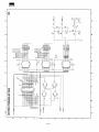
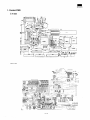
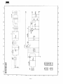
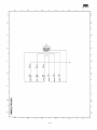
CHAPTER 13. CIRCUIT DIAGRAM & PWB LAYOUT . . . . . . . . . . . 13-1
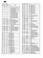
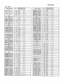
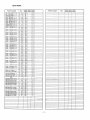
PARTS GUIDE (Except for “KA” version)
PARTS GUIDE (For “KA” version)
/
Parts marked with “A” is important for maintainingthe safety of the set. Be sure to replace these parts with specified
onesfor maintainingthe safetyand performanceof the set.
~~*~~
~~~~~~ATION
Thisdocument has been published to be used
foraftersalesservi~on,y.
The contents are subject to change without notice.
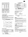
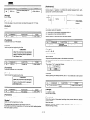
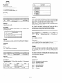
2) Rating
CHAPTER 1. SPECIFICATIONS
VAC 50/601iz
Power
Stand-by: 9W
Printing: 89W
Demand
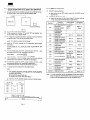
1. Appearance/Rating
178 (W) X 340 (D) X 153 (H)
Outside dimension
1) Appearance
Printercover
bck I
O-40”C
1O-9OYO
Ambient temperature/humidity
4.2kg
Weight
Printer RlecelpI
““
--. .. .
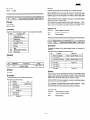
2. Journal lock ( Printer cover lock)
●
Method of locking
Locking:
Rotating clockwise 90”
Unlocking:
Rotating counterclockwise 90”
Key No.:
SK224
panel
Powerswitch
\w
3. Power switch
The power switch (seesaw switch) provided on the lower portion of
the left side of the main unit is used to turn ON/OFF the power
supplied to the printer.
Interface
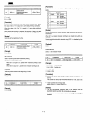
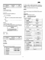
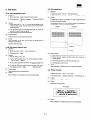
4. Panel switch
The three panel switches provided on the upper portion of the front of
the main unit have the functions shown below.
ON-LINE
Used to switches ON-LINflOFF-LINE (toggle
switch).
RECEIPT FEED
Used to perform manual paper feed on the
receipt side.
Paper feeding is continued while it is ON.
JOURNAL FEED
Used to pedorm manual paper feed on the
journal side. Paper feeding is continued while
it is ON.
?elease
ever
Normalposition
e
5. Panel LED
Paperreleasepositior
The three panel LEDs provided (together with panel switches) on the
upper portion of the front of the main unit have the functions shown
below.
:-.. Printinahead
openposition
POWER LED
Receiptpaperfeedkey
ON-LINE LED
Powerlamp
t
ONLINEkey
ONLINElamp
Frroriamp
Joum~lPaPer
feedkey
ERROR LED
Green
Lighting:
Indicating that the power is
supplied.
Not lighting: Indicating that the power is not
supplied.
Green
Indicating that the ON LINE is
Lighting:
selected.
Not lighting: Indicating that the OFF LINE is
selected.
Red
Indicating that an error is caused.
Lighting:
Not lighting: Indicating that normal operation
is made.
6. Receipt/Journal
1-1
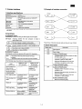
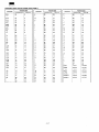
printer: PR-58L
ER-OIF’U
Item
Description
No. of station
2: Receipt and Journal
Validation
No
Printing system
Line thermal
No. of dot
Dot pitch
Font
Receipt:
360 dots
Journal
360 dots
Horizontal:
0.125 mm
Vertical:
0.125 mm
Font A:
12 dot (W) X 24 dot (H)
9 dot (W) X 24 dot (H)
Font B:
Printing capacity
Character size
Print pitch
Font A:
30 digits/line
Font B:
40 digits/line
Font A:
1.5 mm x 3 mm
Font B:
1.13 mm x 3 mm
Column distance:
1.5 mm
Row distance:
3.75 mm
Paper feed speed
Approximate 50 mm/s
Reliability
Mechanism:
Paper end sensor
Yes (Receipt and Journal)
Cutter
PR-58L:
Paper near end sensor
No
MCBF 5 million lines
Auto
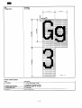
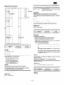
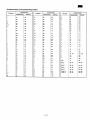
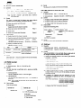
Printing area
832dots
4
(7.0) 4
\
360dots
(45)
❑0
200
+
0.125
I
57.5 *.5
1-2
\
❑ on
‘
*+
4
●
I (5.5)
> —4
I
~ y
5.5
❑c
+ — 47.0
+
3.0
UNIT: mm
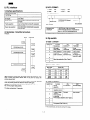
ER-OIPU
Item
Description
Printing format
12x 24 font
1,5(12dots)
●
I
I
t , , , ,
I I
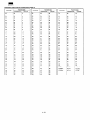
Item
Description
Cut method
●
Full cut (Cut except 1 point)
Cuttable paper thickness
Partial cut (Cut except 3 points)
Heat sensitive paper: 60-80 pmm
Cut’table paper width
57.5 H.5 mm
Reliability
MCBF 300,000 cut
●
I
1-3
1
{
I
{
+
I
1
i
2) Auto cutter section
I
I
1.5(12dots)
+4
I
, , , ,
I
I
I
UNIT: mm
I
ER-OIPU
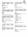
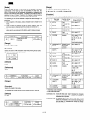
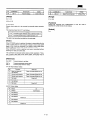
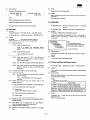
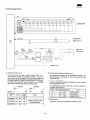
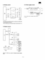
3) Example of interface connection
7. Printer interface
1) Interface specifications
I Interface
Synchronizing mode
Asynchronous
Handshake
DTR/DSR signal control or XON/XOFF
control
●
Baud rate ●
2400/4800/9600/1 9200/38400
Bit length
7 bits/8 bits
●
Parity check *
●
Printer
Host computer
I
I RS232
Even number/Odd number/No
Stop bit
1 stop bit
Connector
D-SUB 9 pin connector
Handshake, Baud rate, Bit length and Parity check are set with the
dip switch.
2) Handshake
A) DTR/DSR control
Handshaking is performed using the DSR signal and DTR signal.
DSR signal : Indicating whether the host computer is ready to
receive data or not.
ON
The host computer is ready to receive data.
OFF
The host computer is not ready to receive data.
The pin Nos. of the host computer side are those for 9-pin D-SUB.
4) Signal description
DTR signal: Indicating whether the printer is in busy condition or not.
ON
OFF
Signal name
The printer is not in busy condition.
The printer is in busy condition.
Description
S. G
Signal ground
TXD
Transmission data
B) XON/XOFF control
RXD
Receive data
Handshaking is performed using the XON and XOFF characters.
DSR
In case of DTR/DSR control
●
XON
Transmitted when the printer returns from busy
condition.
XOFF
Transmitted when the printer gets into busy condition.
Indicates whether the host computer is ready
to receive data or not.
When the DSR signal is ON, the host
computer is ready to receive data.
●
In the following cases, the printer is in busy condition.
BUSY
CONDITIONS
Period betvveenthe
time when the
power is turned ON
and the time when
it becomes possible
to communicate
TIMING OF DTR
OFF OR XOFF
TRANSMISSION
-------------
When the DSR signal is OFF, the host
computer is not ready to receive data.
TIMING OF DTR
ON OR XON
TRANSMISSION
In case of XON/XOFF control
Does not control the printer.
DRT
When it becomes
possible to
communicate
In case of DTWDSR control
Indicates whether the printer is in busy
condition or not.
When the DTR signalis ON, the printer is in
normal condition.
OFF-LINE key entry
Immediately before
OFF-LINE
Immediately before
ON-LINE
Print stop due to no
paper
Immediately before
print stop
Immediately after
recovery from no
paper
HEAD UP
Immediately before
HEAD UP
Immediately after
recovery from
HEAD UP
Switch wait when
executing the macro
Immediately before
switch wait
Immediately after
recovery from
switch wait
Receive buffer full
When available
space becomes 16
bytes or less
When available
space becomes 26
bytes
When the DTR signal is OFF, the host
computer is in busy condition.
In case of XON/XOFF control
Does not control the printer.
1-4
ER-OIPU
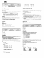
3) DATA FORMAT:
8. IPL interface
1)Interface specifications
1. ENQ :
05h
2. ACK :
06h
3. NAK :
15h
4. EOT :
04h
5. PROGRAM DATA
Asynchronous mode
1 STOP bit
Handshake
Poling (simplified procedure) fixed
Bit length
8 bits fixed
Parity check
Perfoned/Not performed (selected with
DIP SW)
Parity selection
Even number/Odd number/No (selected
with DIP SW)
Baud rate selection
2400/4800/9600/19200/38400 (selected
with DIP SW)
A
PROGRAMDATA(binary)
(256 bytes)
i
SequenceNo.
Checksum
I
Endcode(ODh)
Startcode(02h)
2) Handshake: Simplified procedure
Protocol:
HOST
4
A
PRINTER
Sequence NO.
1 BYTES 30h---39h ring counter
Checksum
Lower 8-bit data of two’s complement of
sum of 1 BYTES PROGRAM DATA
PROGRAM DATA
Binary 256 BYTE fixed DATA
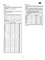
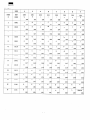
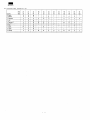
9. Dip switch
1) Table 1. Switch 1
ACK
I
8
t
t
t
I
,
,
[
I
PROGRAM DATA
PROGRAM DATA
1
Handshake
2
Bit length
3
Parity check
4
15
ACK
1
,
,
8
t
t
I,
,
I
1
,
,
m
6
t
8
ON
Function
Switch No.
ACK
,
OFF
XON/XOFF
TDR/DSR
7 bits
8 bits
Performed
Not performed
i
Even number
Odd number
—. selection
I Parity
I Receive
I Receive
I Criteria for
I
I BUSYcondition I BUFFER FULL I BUFFER FULL I
and OFF-LINE
1
I
Baud rate selection (See Table 2.)
I
2) Table 2. Baud Rate
ACK
Switch No.
Baud rate
“6
[BPS]
EOT
q
When receiving program data, the printer checks the checksum. If no
error is found, the printer returns ACK. If any error is found, the
printer returns NAK.
t
7
8
2400
ON
OFF
OFF
4800
OFF
ON
ON
9600
OFF
ON
OFF
19200
38400
OFF
OFF
ON
OFF
OFF
OFF
I
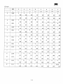
3) Table 3. Switch 2
If the host computer resends the data in spite of the printer returning
ACK, the printer ignores the data and returns ACK again.
Switch No.
(Whether to resend the data be not is judged based on the sequence
NO. in the program data packet.)
Function
ON
OFF
I
MODE
selection
IPL MODE x
Normal MODE
2
in case of data
reception errors
Ignored
Prints “?”
Connect
Not connect
3
In case of data
reception
errors connect
to the host
4
Print density selection (See Table 4.)
.
The time-out period is 10 seconds.
5
6
7
I
Print speed (See Table 5.)
8
X For normal use,do not turn on the IPL mode.
1-5
I
ER-oIPU
Pin arrangement
(Modular jack type connector x 1)
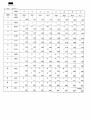
4) Table 4. Print density selection
Print I
density I
Switch No.
I
4
ON
ON
ON
ON
OFF
ON
OFF
ON
OFF
OFF
OFF
ON
OFF
OFF
OFF
ON
ON
OFF
Dark
I
I
OFF
Frame GND
2
Drawer drive si~nal 1
I
3
I Drawer open/close signal
I
4
I +24V
I
5
I Drawer drive signal 2
6
I Signal GND
I
I
Direction
—
Signal name
1
OFF
ON
OFF
Pin No.
6
ON
Light
I
5
I
output
Input
I
output
—
I
I
l–l
I
Connector model No.
OFF
●
Printer side
52065-6615 (MOLEX} or its equivalent
Drawer side
6-pole 6-pin (RJ12 modular jack)
5) Table 5. Print speed selection
I
Switch No.
Print speed
●
It is necessary to obtain the printer side connectors.
7
8
OFF
ON
60 mmls
ON
OFF
Drawerdrivesignal
70 mmls
OFF
OFF
Output voltage:
+24V +5V
Output (peak) current:
1A or less
ON period:
40 msec -50 msec
OFF period:
500 msec or more
50 mm/s
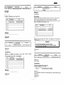
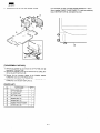
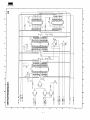
3) Drawer Interface Specifications
10. Drawer inteflace
1) General Description
Drive signal !
As service route options of ER-OIPU, two drawers made by Sharp
(Remote drawer: ER-03DW/04DW) or two modular jack type drawers
(made by EPSON) can be connected.
$
I
ER-03DW
ER-04DW
‘h
ER-04DW
‘1
6
sively.
* When connecting drawers other than ER-03DW/04DW, the drawer
solenoid resistance must be 24 Q or more and the ON period must
be in compliance with the drawer specifications (to prevent overcurrent).
?
ER-03DW
OFF period
Cautions
* Only one drawer can be opened at one time.
* To prevent heating, the same drawer must not be opened succes-
1
ER-01PU
y
ON period
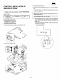
Example of Sharp drawer connection Example of modular jack
tYPe drawer connection
r
,
,
It is necessary to attach the connectors specified as service parts to
the ER-01PU side. (For the service parts, refer to the section of
drawer connector shown below.)
Pc—Y
!-
,
* When connecting drawers other than ER-03DW/04DW, the drawer
connecting cable used must be of the shield type.
I
II
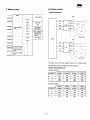
11. Buzzer / Memory/ Backup
Pc 1
I
1)Buzzer
The buzzer is installed on the control substrate.
ER-01PU
Modular jack
type drawer
It informs the user of errors caused during processing. (The type of
error is judged by short sound/long sound, etc.)
Modular jack
type drawer
2) Memory Backup
me electrical double layer condenser is used for memory backup of
the static RAM.
2) Drawer connector
As it is intended to perform memory protection when momentary
power failure is caused, it can not protect memory for a long time.
Pin arrangement (Sharp drawer connector x 2)
pin No. I
1
Signal name
Drawer drive signal
2
Drawer open/close signal
3
+24 V
Direction
Memory maintaining time: About 3 hours after power supply OFF (in
case of full charge)
I
output
Input
—
Memory charging time:
Connector model No.
●
Printer side
5046-03A (MOLEX)
Parts code
QCNCM5278NCZZ2
Drawer side
Attached to ER-03DW/04DW drawer
1-6
From power supply ON (after discharging
for 3 hours or more) to full charge: About
30 minutes
ER-oIPu
Cautions
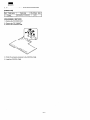
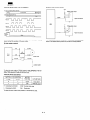
12. Near-end sensor
X When the power supply becomes ON after a long time (6 hours or
more) has passed, the system should be booted by means of
master reset of ER-01PU.
This is necessary because the memory maintaining time is exceeded. By transferring the initial data from the host computer to
ER-01PU by means of master reset, it becomes possible to perform operation even if memory maintaining is impossible.
The optional near-end sensors for journal and receipt are available.
1) General Description
ER-01PU has the connectors for journal and receipt near-end sensors on the control substrate. Therefore, each optional near-end sensor unit can be obtained and attached to ER-01PU.
X As charging is performed when the power supply becomes ON
after a long time, turning ON/OFF of the power of ER-01PU should
be avoided. (Note that there are cases where memory cannot be
maintained due to insufficient charging.)
2) Unit name
Near-end sensor: DUNT-5800BHZZ
3) Detecting method
Rolled paper diameter detecting type
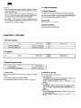
CHAPTER 2. OPTIONS
1. Service options
No.
NAME
1
NEAR END SENSOR
2
DRAWER CONNECTOR
PARTS CODE
DUNT-58
PRICE
RANK
00 BHZZ
AZ
QCNCM52 78 NCZZ
AC
DESCRIPTION
2. Supplies
No.
1
NAME
ROLL PAPER
PARTS CODE
TPAPR66
56RCfI !i
PRICE
RANK
DESCRIPTION
BA
3. Special service tools
No.
NAME
PARTS CODE
1
MASTER ROM
VH i 2704
ORAY 1 A
2
SOFTWARE FOR SERVICE
UK~G-67
23 RCZIZ
1. Master ROM
2. Software for service
This is the EP-RPM used to write the ER-01PU software into the flash
memory.
The following software is provided in FD.
1) IOIPUDIAG.EXE]
fiis software is used to execute the diagnostics of the ER-01PU
through RS232 by the remote operation from PC.
For the operating procedures, refer to ‘CHAPTER 11. IPL
MODE.’
2) [lPL.EXEl
This software is used to write the ER-OIPU application program
IEROIPU,S] from PC into the flash memory of the ER-01PU.
For the operating procedures, refer to *CHAPTER 11. IPL
MODE.=
3) IEROIPU.S]
This is an application program which is written into the ER-OIPU
by the use of [lPL.EXEl.
For the operating procedures, refer to ‘CHAPTER 11. IPL
MODE.’
It is used when replacing the flash ROM in repair,
For the operating procedures, refer to “CHAPTER 11. IPL MODE.”
1-7
ER-OIPU
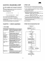
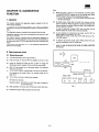
3. RESUMPTION mode
CHAPTER 3. INITIAL PROCESSING
following five modes are available
The
Print:
when turning ON the power
(performing initial processing).
Key sequence
Mode
Operation
The printer clears the
preset data/receive
buffer and starts
ooeratina.
MASTER
RESET mode
Turn ON the power
while pressing the FUJ
key.
IPL mode
For details, see the CHAPTER 11, IPL
FUNCTION.
RESUMPTION
mode
Turn ON the power.
DIAG mode
HEXADECIMAL
DUMP mode
I
Display: The ONLINE lamp is turned ON when the printer gets
ready to receive data from the host computer.
4. DIAG mode
The printer resumes
the printing
interrupted by power
failure.
Turn ON the power
while pressing the J
key.
The printer performs
the DIAG operation.
Turn ON the power
while pressing the R
key.
The printer prints the
data sent from the
host computer, using
hexadecimal digits
and characters
corresponding to
them.
For details, see the CHAPTER 10. DIAG FUNCTION,
5. HEXADECIMAL mode
Print:
123456789012345678901
For details, see the CHAPTER 6. HEXADECIMAL DUMP FUNCTION.
Print: The DIP switch settings are printed.
BPS
234567890
19200BPS
BIT FORMAT
8B I T
24WBPS/4600BPS19600
BF’~
19200BPS136400BPS
8BlT/7BlT
PARI TY
ODD
EVEN/ODD/NONE
HANDSHAKING
XON/XOFF
DTWDSR
BUSY CONDIT 10N
BUFFER FULL
OFFLINE
PRINT DENSITY
LEVEL1
LEVEL1-4
PRINT SPEED
50mm/S
50,60,70 mtiS
NO.
1A
VERS!ON
-----------------------------------
234567890
Hexadec i maI Dump
1. MASTER RESET mode
123456789012345678901
***MASTER RESET
The printer resumes the printing interrupted by a power
fafiure.
When a power failure occurs during printing, performs
power failure mark “== = = =“ and executes the printing
again.
The power failure mark can be set in the [ESC] sequence.
ROMVersion
-—
4
~
Full cut
Display: The ONLINE lamp is turned ON when the printer sets ready
to receive data from the host computer.
2. IPL mode
For details, see the CHAPTER 11. IPL FUNCTION.
3-1
ER-OIPU
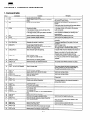
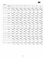
CHAPTER 4. COMMAND DESCRIPTION
1. Command table
[Ln
IFFl
3
[RS]
4
[CAN]
Cancels print data.
In the standard mode, one line of data in the
receive buffer is cleared.
In the page mode, all the print data is canceled.
5
6
7
[s1]
[DC2]
[DLE] IEO~ [n]
Selects character height reduction.
Cancel character height reduction
Transmits status in real time.
8
[DLE] [ENQ] [n]
Requests the printer in real time.
9
[ESC] IFFl
10
[ESC] [SP] [n]
Causes page-mode data print.
All the data expanded to the whole print area is
printed in the page mode.
Sets character right-side spacing.
Causes print and line feed.
Causes page-mode print and return to standard
mode.
Causes journal tabulation.
11 [ESC] ! [n]
Sets character mode.
Font, height and width are set.
12
13
14
Sets absolute print starting position.
Selects/cancels user-defined character.
Defines user-defined character.
15
[ESC] $ [nl] [n2]
[ESC] % [n]
[ESC] & [03] [n] [m] [a[p]sxa]
m-n+l
[ESC] ● [m] [nl] [n2] {[data]}k
16
17
18
19
20
21
22
[ESC] -[n]
[ESC] 2
[ESC] 3 [n]
[ESC] 4 [n] [data] 45xn
—
[ESC] = [n]
[ESC] ? [n]
Selects/cancels underline.
Selects 30/203 inch (30 dot) line feed.
Sets line feed amount.
Sets logo stamp.
—
23
24
25
26
27
28
[ESC] @
[ESC] J [n]
[ESC] L
[ESC] N
[ESC] O
[ESC] NAK [n]
29
30
31
32
[ESC] R [n]
[ESC] S
[ESC] V [n]
[ESC] \ [nl] [n2]
Initializes printer.
Prints and feeds paper.
Switches from standard to page-mode.
Turns buzzer ON.
Turns buzzer OF.
Turns buzzer ON and OFF for a cefiain period of
time.
Selects international character.
Switches from page to standard mode.
Sets/cancels 90” clockwise rotated character.
Sets relative position.
-,. I lts~]
----- a lnj
.33
34
35
[ESC] CO[n]
[ESC] cl [n]
36
[ESC] C4[n]
Remarks
Function
Command
No.
1
2
Valid for page-mode print. This command causes
the printer to stafi printing.
Moves the print position to the beginning of
journal.
(Valid only when the printing of the same data on
receipt/journal has been canceled.)
In the page mode, all the data in the receive
buffer is cleared.
In the standard mode, one line of data with no
print command is cleared (for recovery from
power failure).
Valid only at the beginning of a line.
Valid only at the beginning of a line.
I Transmits regardless of the state of the host
computer.
Transmits regardless of the state of the host
I computer.
Valid for page-mode.
This command causes the printer to start printing.
The page mode is maintained after printing.
If double-width mode is selected, the amount of
space is doubled.
Space is provided on the right side of each
character even in case of lateral turning.
If there are characters of different modes in one
line, they are printed with their bases aligned.
~“AAAAA”
The preset user-defined character is called.
‘ This image shows the same movement as a
normal character (it can be printed using LF).
The setting is possible during printing.
Sets bit image data.
Sets peripheral device,
Deletes user-defined character.
Aligns print data positions
Selects print sheet (FUJ).
Selects print sheet (R/J) covered by line feed
amount setting. Valid even during printing.
Selects paper-out detector to stop printing.
4-1
Valid even during printing.
Valid even during printing.
(Reserved)
The same pattern as the internal character is
~printed after deletion.
I
Valid only at the beginning of a line.
Valid only at the beginning of a line.
Sets the print starting position based on the
current position.
Valid only at the beginning of a line.
Valid only at the beginning of a line.
ER–OIPU
No.
37
38
Command
[ESC] C5[n]
[ESC] d [n]
39
40
41
42
43
44
45
46
47
[ESC]i
[ESC] m
Function
Enables/disables panel switch.
Prints and feeds paper by the specified number of
lines.
Causes full cutting
Causes partial cutting
Prints stamp.
[ESC] O
[ESC] p [m] [tl] [t2]
[ESC] q [data]
[ESC] t [n]
[ESC] u [n]
[ESC] V
[ESC] z [n]
50
[ESC] { [n]
[GS] ! [n]
[GS] [nl ] [n2] [data] nl xn2x8
51
52
53
[GS] t [n]
[GS] :
[GS]A[r] [t] [m]
54
55
56
57
58
59
60
61
62
[GS] E [n]
[GS] H [n]
[GS] I [n]
[GS] P [nl] [n2]
@ [GS] V [m] @ [GS] V [m] [n]
[GS] a [n]
[GS] f [n]
[GS] h [n]
@ [GS] k [m] [data] k [00]
@ [GS] k [m] [n] [data]
[GS] r [n]
[GS] w [n]
48
49
63
64
Generates specified pulse,
Sets power failure mark.
Selects character code table.
Transmits drawer connector status.
Transmits paper detector status.
Sets/cancels the printing of the same data on
receip~oumal.
Sets/cancels upside-down character printing.
Selects character size.
Sets image data.
nl: Horizontal size n2: Vertical size
Prints image data.
Sets starting/ending position of macro definition.
Executes macro.
Remarks
Valid only at the beginning of a line.
Valid only at the beginning of a line.
Valid only at the beginning of a line.
Valid only at the beginning of a line.
Valid only at the beginning of a line.
The number of times, interval and mode of
execution can be set.
Selects print density.
Select printing position of HRI character
Transmits printer ID.
Sets basic line feed pitch.
Cuts paper.
Enables/disables automatic status transmission.
Selects font for HRI character.
Selects height of barcode.
Selects bar code system and prints bar code.
ROM version etc. are transmitted.
Valid only at the beginning of a line.
Font A and Font B can be set.
Number of dots.
Status: Same as [ESC] v and [ESC] u.
Transmit status.
Selects horizontal size of barcode.
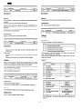
2. Command description
?
No.
COMMAND
1
LF
FUNCTION
Print and line feed
CODE
No.
COMMAND
<OAh>
2
FF
[Function]
[Function]
Standard mode)
Standard mode)
Prints data in the print buffer and advances the paper by the
previously set amount.
Moves the print position to the beginning of the next line.
FUNCTION
Page mode print and return
CODE
<OCh>
No function
Page mode)
Prints all the print data in one page.
Then returns to the standard mode.
The print data is all erased after printing.
Page mode)
Does not print data in the print buffer.
Advances the paper by the previously set amount.
Moves the print position to the beginning of the next line.
[Notes]
This command is valid for the page mode only.
[Reference]
The print position is moved to the beginning of the next line.
[ESC] 2: Sets the line feed amount to 30/203 inch (30 dots).
Paper cutting is not performed.
[ESC] 3: Sets the line feed amount.
To perform paper cutting, it is necessary to send the paper cut command before sending this command.
Print data put in line feed codes is printed.
[Reference]
[ESC] FF: Remains in the page mode.
4-2
ER-OIPU
No.
COMMAND
3
RS
FUNCTION
Journal tab
CODE
No.
COMMAND
FUNCTION
<1Eg>
6
DC2
Cancel character height reduction
CODE
<12h>
[Function]
[Function]
Moves the print position to the beginning of journal paper.
Cancels character height reduction.
[Notes]
[Notes]
This command is valid only when receip~ournal same data printing is
canceled.
This command is valid only when set at the beginning of a line.
ERO1PU cannot print data during receip~ournal,
[Reference]
However, print data can be edited and set during receiptijournal in
light of data compatibility, for ordinary receiptijournal printers can print
data then.
[S1]: Select character height reduction
Therefore, be sure to set this command at the beginning when setting
the print data in the journal side.
No.
COMMAND
7,
DLE EOT n
FUNCTION
CODE
Transmit status in real time
CI Oh><04h>n
[Reference]
[Range]
[ESC] Z: Select/cancel R/J same data printing
ISn
FUNCTION
I No. I COMMAND I
I Cancel print data
CAN
141
I
CODE
S4
[Function]
I
Transmits the status in real time by setting “n”.
Function
n
[Function]
1
Transmits the printer status.
Standard mode)
2
Transmits the offline factor status.
3
Erases one line of print data not put in line feed codes in the
receive buffer.
4
Page mode)
Transmits the error factor status.
I Transmits the paper detector status.
This command is executed regardless of the state of the host computer. (The DSR signal is not checked.)
Erases one page of print data not put in FF codes in the receive
buffer.
Moves the print position to the beginning of journal paper.
This command is executed even if offline, receive buffer full or error
states are provided.
Status transmission is made immediately when this command is
received.
[Notes]
When print data may be missed due to power failure, etc. during
printing, it is necessary to resend print data after recove~ for correct
printing. This command is provided mainly for such cases.
n=l; Printer status
bit I
Function
o Not used
1 Not used
2 Drawer status
3 Online/Offline state
4 Not US~d
5 Not defined
6 Not defined
7 Not used
In the standard mode, it is possible to cancel a line for which power
failure is caused during receiving.
In the page mode, it is possible to cancel a page for which power
failure is caused during receiving.
No.
COMMAND
5
SI
FUNCTION
CODE
Selects character heiaht reduction I <OFh>
Value 0/1
Fixed to O
Fixed to 1
“L’’/’’H”
online/Offline
Fixed to 1
Fixed to O
n=2; Offline factor status
bit
Function
0 aNot used
1 Not used
2 HEAD UP LEVER
Q I Paper feed SW
[Function]
Starts character height reduction.
Reduces the character height to 1/2 by removing bits one by one.
u
[Note]
[Reference]
4
5
6
Not used
Print stop due to no paper
Error state
[DC2]: Cancel character height reduction
7
Not used
This command is valid only when set at the beginning of a line.
Value 0/1
Fixed to O
Fixed to 1
Close/Open
Paper not being fed/Paper
being fed
Fixed to 1
Not stopping/Stopping
No error caused/Error
caused
Fixed to O
.
bit 5; Becomes 1 in case of print stop set by IESC]CO and
[ESC]C4.
4-3
ER-OIPU
[Function]
n=3; Error factor status
Standard mode)
Value 0/1
Function
bit
o
Not used
Fixed to O
1
Not used
Fixed to 1
2
RS232 Receive Error
No error caused/Error caused
3
Auto cutter error
No error caused/Error caused
4
Not used
No function
Page mode)
Prints all the print data in one page.
Then remains in the page mode.
The print data is all erased after printing.
Fixed to 1
I No error caused/Error caused
5 / Unrecoverable printer
error
[Notes]
6
Head temperature rise
7
Not used
No error caused/Error caused
This command is valid for the page mode only.
Fixed to O
The print position is moved to the beginning of the nefi line.
Value 0/1
To perform paper cutting, it is necessary to send the paper cut command before sending this command.
Paper cutting is not performed.
n=4; Paper detector status
Function
bit
o
Not used
Fixed to O
1
Not used
Fixed to 1
2
Near end detector
3
Not used
Fixed to O
4
Not used
Fixed to 1
5
Journal end detector
Paper is presentiPaper is out
6
Receipt end detector
Paper is present/Paper is out
7
Not used
Print data put in line feed codes is printed.
Paper is presentiPaper is out
[Reference]
FF: Return to the standard mode afier pdnting.
Fixed to O
FUNCTION
I No. I COMMAND ~
I
[Notes]
10
ESC SP n
Set character right side
spacing
I
I
CODE
I
<1Bh><20h> n
I
Status transmission is also made when data of IOh, 04h and n (1 S n
5 4) is received.
<Example>
In case of Dl=l Oh, D2=04h and D3=Olh with ESC * nl n2 [DATA] k.
[Function]
No.
8
COMMAND
DLE ENQ n
CODE
FUNCTION
Request status in real time
Sets the space on the right side of each character in basic calculation
pitches.
f
The space on the right side of each character is [n x (basic calculation pitch)] inches.
<1Oh>c05h>n
[Range]
[Notes]
If double-width and quadruple-width are selected, the amount of
space on the right side of each character is doubled and quadrupled.
[Function]
Space is provided on the right side of each character even in case of
lateral turning.
Responds to requests from the host computer by setting “n”.
Inl
Function
1
[n x (basic calculation pitch)] is calculated when this command is
received.
I
Recovers from the error and restarts printing at the
beainnina of the line where the error is caused.
Therefore, this setting is not changed only by changing the basic
calculation pitch through GS P.
Restarts printing after clearing the receive buffer and print
buffer.
z
[Default]
This command is executed regardless of the state of the host computer. (The DSR signal is not checked.)
n=O
This command is executed even if offline, receive buffer full or error
states are provided.
[Reference]
GS P:
This command is executed immediately when it is received (without
being entered in the receive buffer).
GS !:
L
No.
COMMAND
9
ESC FF
FUNCTION
Page mode print
Set basic calculation pitch
ESC!:Set character mode
Set character size
[Print example]
AAAA
UAA
CODE
<1Bh><OCh>
4-4
ER-OIPU
[Function]
FUNCTION
I No. I COMMAND /
I 11 I
ESC!n
I
I
Setcharacter mode
CODE
\ <l Bh>c21h>n
Based on the beginning of the line, sets the print starting position
through calculation using the basic calculation pitch.
I
I
The distance between the print starting position and the beginning of
the line is as follows.
[Range]
(m+ n x 256)x (basic calculation pitch)
O S n S 255
-[Notes]
[Function]
Any specification that exceeds the end of the line is ignored.
Selects the character mode.
(The end of the line: Receipt width when R/J same data printing is
selected; Receipt width + Journal width + Width between R/J when
R/J same data printing is canceled)
The meaning of each bit of “n” is as follows.
Function
bit
O:Character font 12 x 24
o
This calculation is made based on the basic pitch in the horizontal
direction.
1: Character font 9 x 24
111
Not defined
In case of overlapping with the print data expanded currently, overprinting is performed.
I
Not defined
2
Not defined
3
4
O:Double-height canceled
[Reference]
1: Double-height selected
ESC\: Set relative position
O:Double-width canceled
5
1: Double-width selected
Not defined
6
I
No.
COMMAND
O:Underline canceled
7
13
1: Underline selected
ESC ‘/0 n
FUNCTION
Select/cancel
user-defined character
CODE
<1Bh><25h> n
[Notes]
No underline is provided in the following cases.
1) Portions skipped with journal tab
2) Laterally-turned character
[Function]
3) Blank portions specified by set absolute position/set relative
position
Selects or cancels the mode for make printable the preset userdefined character data.
bit Oof “n” = 1: User-defined character selected
When both double-height and double-width are selected at the same
time, quadruple characters are printed.
bit Oof “n” = O:User-defined character canceled
This setting can be changed within one line.
[Notes]
If there are both double-height characters and normal characters in
one line, they are aligned on the base line.
●
[Default]
n=o
. When the character code set for user-defined character is selected
after selecting the user-defined character mode, the user-defined
character is printed.
●
[Reference]
GS P:
When the character code not set for user-defined character is
selected, the normal character is printed.
Set basic calculation pitch
[Default]
ESC !: Set character mode
GS !:
There are other jobs for user-defined character setting.
n=O
Set character size
[Reference]
[Print example]
ESC &: Set user-defined character
AAAAAAAA
—
ESC ?: Delete user-defined character
No.
COMMAND
FUNCTION
CODE
12
ESC $ m n
Set absolute position
<1Bh>c24h> n
[Range]
O S m S 255
0 S n S 255
4-5
ER-OIPU
No.
14
COMMAND
ESC & 03 Cl C2
(n[DATA]nx3)
C2-C1
[Range]
32s cl s cz S 1~6:
FUNCTION
Define
user-defined
character
CODE
<1Bh><26h><03h>
f
User-defined character range
(cl to C2)
DATAn S 255: Print bit data
O S DATA1 ~~~
O ~ n 59:
9 x 24 font selected
O S n S 12:
12x 24 font selected
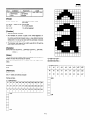
[Function]
●
Sets user-defined characters.
●
03h indicates the number of bytes in the vertical direction. Cl
Indicates the beginning user-defined character code; C2 indicates
the ending user-defined character code. 000User-defined character
setting from Cl to C2 can be made with this command. If only one
character is defined, use C1=C2.
●
The character code range is from ASCII code 20h to
total number of characte~s is 95,
7Ehand the
[Example]
[ESC]&0332
3312 [DATAI].....[DATA36] 12 IDATA1].....[DATA36]
CIC2
n
n
tiI f
[Notes]
The set user-defined character data is not cleared until the MASTER
RESET and ESC @ commands are received.
,
,
r
1
1
1
r
I I
I
,
1
!
1
I
!
1
I
I
r
I
I
I
1
II
dl =<OOh>d4=<l 8H>.....
d2=<OOh>d5=<63h>.....
d3=<EOh>d6=<F8h>..,..
If the above-mentioned data is out of the range, the setting is disabled.
[Default]
●
n=O
I
[Reference]
In case of font B
dl
d4
d7
d10
d13
d16
d19
d22
d25
d2
d5
d8
dl 1
d14
d17
d20
d23
d26
d3
d6
d9
d21
d24
d27
ESC Y.: Select/cancel user-defined character
ESC ?: Delete user-defined character
I
n
MSB
In case of font A
dl
d4
d7
d10 d13 d16 d19
d2
d5
d8
dl 1 d14 d17 d20 d23 d26 d29 d32 d35
d3
d6
d9
d12 d15 d18 d21
t-l
I
d12
I
1
Setting example)
●
1
d22 d25 d28 d31 ds
d24 d27 d30 d33 d36
MSB
LSB
4-6
d15
I
d18
I
I
1
ER–OIPU
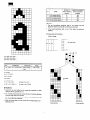
The image modes selectable by “m” are as follows.
●
.
m
Number of
dots in vertical
direction
Mode
Maximum number of
dots in horizontal
direction
o 8-dot single-density
8
192
1
8-dot double-density
8
360
32 24-dot single-density
24
192
33 24-dot double-density
24
360
[Notes]
●
●
The set user-defined character data is not cleared until the
MASTER RESET and ESC @ commands are received.
If the above-mentioned data is out of the range, the setting is
disabled.
Bit image data print example)
8-dot bit image
TI
I
MS B
Bit image data
dl
d2
LSB
1
,
1
,
I
,
I
f
I
I
I
d3
dl=<OOh> d4=<l 8H>.....
d2=<OOh>d5=<63h>.....
d3=<EOh> d6=<F8h>,,,,,
No.
COMMAND
I FUNCTION
15 f ESC * m nl n2 [DATA] k ~Set bit image
I data
CODE
/\
<1Bh><2Ah>...
\
[Range]
m = O, 1, 32, 33
0 S nl S 255
Print data
fl means 1 dot
0 S n2 S 3
0 S data S 255
k = nl + n2 x 256
(in case of m = 0,1)
k = (nl + n2 x 256) x 3
(In case of m = 32,33)
[Function]
●
Expand to the print buffer the bit image data specified by “data”
using the density specified by “m”.
●
(nl +n2x256) represents the number of dots in horizontal direction
of the bit image data to be printed.
●
If the bit image data exceeds the number of printable dots in one
line, the excess data is ignored.
●
When the image data is to be printed, the corresponding bit is 1;
otherwise it is O.
Single-density
4-7
Double-density
ER-OIPU
24-dot bit image
— — —
dl
i4
MS B
j3
No.
COMMAND
16
ESC - n
FUNCTION
Select/cancel underline
CODE
<1Bh><2Dh> n
Bit imaae data
[Function]
—
d2
—
!5
[
—
LSB
Selects or cancels the underline.
~6
●
When n=Oor 48, the underline is canceled.
●
When n=l or 49, the 2-dot-wide underline is selected.
●
When n=2 or 50, the 3-dot-wide underline is selected.
[Notes]
—
—
—
No underline is provided in the following cases.
1) Portions skipped with journal tab
43
2) Laterally-turned character
16 ~7
3) Blank portions specified by set absolute position/set relative
position
—
The same processing as “select./cancel underline” using ESC ! is
pedormed.
— —
[Default]
dl
n=O
[Reference]
ESC !
I No. I COMMAND I
I I
17
—
ESC 2
FUNCTION
Set 30/203 inch line feed
amount
I
CODE
Bh><32h>
I <1
[Function]
Sets the distance for one line feed to 30/203 inch.
me line spacing is 6 dots.
Caution
Print data
a means 1 dot
In case of double-height, the line spacing is Odots.
If the line spacing is less than 6 dots,
printing may be disturbed when printing is started
from the printer stop state.
In this case, printing must be made with the printer
in the operating state
(continuous printinq from the nrevious line).
[Reference]
ESC 3: Set line feed amount
Single-density
Doubiedensity
4-8
I
I
ER-OIPU
FUNCTION
CODE
No.
Set line feed amount
<1Bh><33h>
20
No. I COMMAND
I 18
ESC3n
1
21
Sets the distance for one iinefeed
inch.
to[nx(basic
ESC = n
CODE
(Reserved)
FUNCTION
CODE
Set peripheral device
<1Bh><3Dh> n
COMMAND
No.
[Function]
FUNCTION
—
COMMAND
—
calculation pitch)l
Caution
[Function]
ffthefine spacingislessthan 6ctots,
printing maybe disturbed
when printingis started from the printer stop state.
In this case, printing must be made with the printer
in the operating state
(continuous printing from the previous line).
Sets the operation of the peripheral devices.
bit ‘
Peripheral device
1/’0
Printer
Valid/Disabled
o
[Default]
[Default]
n=3
n = 30 (30/203 inch)
[Reference]
No.
ESC 2: Set 30/203 inch line feed amount
COMMAND
22
No.
COMMAND
FUNCTION
CODE
19
ESC 4 n [DATA] k
Set logo stamp
<1Bh>c34h> n ...
ESC ? n
FUNCTION
Delete user-defined
character
<1Bh><3Fh> n
[Range]
32 : n ~ 126
[Function]
[Range]
O~ n ~ 160: Number of dots in vertical direction
Deletes the user-defined character for the specified code.
k = 45x n
INotes~
[Function]
The specified code is set to the normal character.
Sets the logo stamp.
[Reference]
Setting is made with side slice.
ESC &: Set user-defined character
Stamp setting of MAX 20 mm in vertical size is possible.
ESC O/.: Select user-defined character
[Notes]
6-dot feed is performed before the logo stamp data is printed.
[Default]
n= 160 (30/203 inch)
DATA =
CODE
YOUR RECEIPT
THANK YOU
[Reference]
ESC o: Print logo stamp
[Notice]
ERO1PU can not receive a data during writing the logo stamp data in
internal memory.
ERO1PU inform it to host by sending XOFF character or turning off
DTR signal.
When you turn off ERO1PU or you execute Master Reset,this data is
remained.
So,you need not to execute it frequently.
4-9
ER-OIPU
No.
COMMAND
ESC @
23
FUNCTION
initialize printer
No.
CODE
28
<1Bh><40h>
FUNCTION
COMMAND
ESC NAK n
Buzzer ON/OFF
[Function]
[Range]
Initializes the printer setting data.
O S n S 255
[Notes]
[Function]
me following data are not initialized.
Makes the buzzer ON/OFF for a certain time.
CODE
<1Bh><l 5h> n
(n x1Omsec)
Macro setting data
Receive buffer data
Stamp data
Y
No. COMMAND
t
No.
COMMAND
FUNCTION
CODE
24
ESC J n
Print and feed paper
<1Bh><4Ah>
29
ESC Rn
FUNCTION
CODE
Select international character
<1Bh>c52h>
[Range]
O S n S 255
[Function]
[Function]
Selects a character set among those shown in the table below according to the value of “n”.
Prints the data in the print buffer and feeds the paper for “n x (basic
calculation pitch)”.
Inl
Character set
I
I
I O I U.S.A.
1 France
2
No.
COMMAND
FUNCTION
CODE
25
ESC L
Select page mode
<1Bh><4Ch>
Germany
I
I 3 I U.K.
[Function]
Switches from the standard mode to the page mode.
7
Spain
8
Japan
[Notes]
1 9 I Norway
This command is valid only when entered at the beginning of a line.
I 10 I Denmark II
I
I
[Reference]
[Notes]
FF: Prints the page data
If “n” is out of the range, this command is ignored.
[Default]
No.
COMMAND
FUNCTION
CODE
26
ESC N
Buzzer ON
<1Bh><4Eh>
n=O
●
[Function]
No.
COMMAND
Sounds the buzzer,
30
ESC S
FUNCTION
Select standard mode
CODE
<1Bh><53h>
[Function]
No.
COMMAND
FUNCTION
CODE
27
ESC O
Buzzer OFF
<1Bh><4Fh>
Switches from the page mode to the standard mode,
[Notes]
This command is valid only when entered at the beginning of a line.
[Function]
Stops the buzzer.
[Reference]
ESC L: Select page mode
4-10
ER–OIPU
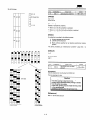
Example
No.
FUNCTION
COMMAND
31
ESC V n
i Set/cancel 90ciockwise
rotated character printing
<1Bh>e56h> n
[Range]
m=254, n=255
3 dots to the left:
m=253, n=255
The distance between the print starting position and the beginning of
the line is as foiiows.
Sets or cancels 90” cw (clockwise) rotated character printing according to the value of “n”.
Function
I Cancels 90” cw rotated character Drintina
1 1, 49
m=255, n=255
360 dots to the left: m=154, n=254
[Function]
Inl
I 0,48
1 dot to the left:
2 dots to the left:
CODE
I Sets 90” cw rotated character printing
N x (basic calculation pitch)
I
I
[Notes]
●
Any specification that exceeds the end of the line is ignored.
(The end of the line: Receipt width when R/J same data printing is
selected; Receipt width + Journal width + Width between FUJwhen
R/J same data printing is canceled)
●
This calculation is made based on the basic pitch in the horizontal
direction.
●
In case of overlapping with the print data expanded currently, overprinting is performed.
I
[Notes]
No underline is provided for 90° cw (clockwise) rotated characters.
Double-width/double-height setting is reversed.
If “n” is out of the range, this command is ignored.
[Default]
[Reference]
n=O
ESC $: Set absolute position
[Reference]
ESC SP: Right margin setting valid
ESC !:
I No. I COMMAND I
33
ESC a n
No underline is printed.
I
Double-width/double-height setting is reversed.
No.
32
COMMAND I
ESC \ mn
I
FUNCTION
CODE
Set relative position
<1Bh><5Ch> mn
I
I
Aligns all the data in one line to the specified position.
O S m S 255
m
The value of “n” specifies the alignment as follows.
0 S n S 255
n
O,48
[Function]
Based on the current position, sets the print starting position through
calculation using the basic calculation pitch.
●
CODE
<1Bh>e61 h> n
[Function]
[Range]
●
I
FUNCTION
Align positions
A positive number specifies the print starting position to the right of
the current position; a negative number to the Ieti.
Position
Align left
1, 49
Align center
2,50
Align right
[Notes]
This command is valid only when set at the beginning of a line. Blank
portions specified by set absolute position/set relative position are
also covered by this command.
Negative numbers are specified using the supplement of N.
The print starting position is determined through the following calculation.
Position alignment is performed separately for R and J,
To the right
m + n x 256 = N
[Default]
Example
n=O
1 dot to the right:
m=l, n=O
2 dots to the right:
m=2, n=O
3 dots to the right:
m=3, n=o
[Print example]
360 dots to the right: m=104, n=l
To the left
m + n x 256 65536– N
4-11
Align left
Align center
~,
El
“
~
“
ER-OIPU
ESC c On
34
Select print sheet (R/J)
No.
CODE
FUNCTION
COMMAND
No.
<1Bh><63h><30h> n
36
ESC c 4 n
*
[Range]
o~n~z
CODE
FUNCTION
COMMAND
Select paper-end
detector to stop
printing
<1Bh>c63h>c34h> n
[Range]
O S n S 255
[Function]
Enables or disables the print sheet (FVJ).
[Function]
The meaning of each bit of “n” is as follows.
Selects which paper-end detector causes the printer to stop printing.
bit
Description
0/1
o
Journal printer
Disabled/Enabled
1
Receipt printer
Disabled/Enabled
When printing is stopped, the line being printed is completed.
Even if printing stop is invalid, the printer stops printing and the print
data is discarded when the paper is out.
The meaning of each bit of “n” is as follows.
2
3
Near-end detector
InvaliWalid
2
Journal end detector
Invalitialid
3
Receipt end detector
Invalid/Valid
o
5
0/1
Description
bit
I
41
1
6
I
71
4
5
[Notes]
6
Valid only at the beginning of a line
7
[Default]
[Notes]
n=3
Whether the printer goes OFF-LINE or not depends on the setting of
the dip switch.
Caution
ESC c 1 n
35
CODE
FUNCTION
COMMAND
No.
Select print sheet
covered by line teed
amount settina
When the presetting of Receipt is different form Journal
and if the line spacing is less than 6 dota,
printing may be disturbed when printing is started
from the nrinter stoo state.
<1Bh><63h><31 h> n
[Range]
[Default]
OSn S3
n=O
[Function]
Enables or disables the data of line feed
(ESC2/ESC3) by print sheet (receipt/journal).
amount
setting
The meaning of each bit of “n” is as follows.
bit
Description
0/1
o
Journal printer
DisabledfEnabled
1
Receipt printer
Disabled/Enabled
I I
37
ESC c 5 n
Enable/disable
Danel switch
I
cl Bh>e63h>c35h> n
I
2
3
[Function]
4
5
Enables or disables the panel switch.
6
Only the lowest bit of “n” is valid.
7
When n=*******O,the panel switch is enabled.
When n=*******1, the panel switch is disabled.
[Notes]
Valid only at the beginning of a line
[Notes]
[Default]
This command is valid for the receipt feed key, journal feed key and
online key,
n=3
[Default]
n=O
4-12
ER-OIPU
[Reference]
No.
ESC d n
38
Print and feed paper “n”
lines
A distance of 16.8 mm is provided between the cutter position and
thermal head c1 position. In printing the stamp between them, vertical size of 15.8 mm can be used.
CODE
FUNCTION
COMMAND
<1Bh>.c64h> n
.- ---
~
7
1
.-..-J........;.-.
.......
16.8mm
I
‘P
15.8mm
I +
------
[Function]
Prints the data in the print buffer and feed the paper for “n” lines.
Cutterposition
Stamp
~
Print position
(Thermalhead
position)
[Default]
n=O
The following methods are used to print the stamp data between the
cut position and print position.
1) Execution of print stamp command (ESC o)
No.
COMMAND
FUNCTION
39
ESC i
Full cut
2) Execution of cut command (ESC 1)
CODE
<1Bh><69h>
Stamp printing in this case is for the next receipt.
[Function]
Executes a full cut of the paper.
I
[Notes]
42
ESC p m tl t2
Generate
specified pulse
I <1
Bh><70h> p m tl t2
I
Valid only at the beginning of a line
I
Causion:
[Range]
I
m = O,1, 48, 49
After this command is executed,
You had better execute one line
feed or one line print to prevent
the Paper Jam.
0 S tl S t2 S 255
[Function]
Outputs the specified pulse on the drawer connector.
No.
COMMAND
FUNCTION
CODE
40
ESC m
Partial cut
<1Bh><6Dh>
For connector pin “m”, the signal is held ON for tl x 2 ms and OFF for
t 1 x2 ms.
The value of “m” is used as follows.
[Function]
Executes a partial cut of the paper.
[Notes]
[Notes]
Valid only at the beginning of a line
When opening the Sharp drawer, 20 S tl S 25 and 250 S t2 must be
applied.
I
Causion:
P
I
feed or one Ime print to prevent
No.
41
COMMAND
ESC O
I I
43
FUNCTION
Print stamp
ESC q DATA
Set power failure
ma~
I <1
Bh><71h> DATA
I
[Range]
CODE
<1Bh><6Fh>
O S DATA S 255
DATA: ASCII code
[Function]
Stamp printing of MAX 20 mm in vertical size is performed.
[Function]
[Notes]
Prints the mark of interrupted printing when power failure is caused
during printing.
Valid only at the beginning of a line.
Sets this mark.
The stamp data is printed on the receipt side only.
Performs one-line printing of this character when power failure is
caused during printing.
6-dot feed is performed regardless of the line feed pitch setting before
the stamp data is printed.
4-13
ER-OIPU
[Default]
[Notes]
DATA : “=” (3Dh)
If nothing is connected to the connector, bit Ois always equal to O.
No.
FUNCTION
CODE
Select character code table
<1Bh><74h> n
COMMAND
ESC t n
44
When DTWDSR control is selected, the status is transmitted after the
printer confirms that the host computer is ready to receive data (DSR
signal is ON). If the host computer is not ready to receive data (DSR
signal is OFF), the printer waits until the computer is ready.
When XON/XOFF control is selected, one byte is transmitted without
checking if is ready to receive data.
This command is executed during receive buffer expansion. Therefore, if there is other data in the receive buffer, some delay may be
caused between command receiving and status transmitting.
[Reference]
[Function]
Selects the character listed on page “n” of the character code table.
Page
I
Character type
o
USA:EUROPE
1
Japanese (Katakana)
2
Multilingual
3
Portuguese
4
I’Canadian-French
5
Nordic
6
Greece
I
DLE EOT:
Transmit status in real time
GS a:
Transmit automatic status
GS r:
Transmit status
No.
COMMAND
FUNCTION
CODE
46
ESC V
Transmit paper detector status
cl Bh><76h>
[Function]
Transmits the status of the paper detector when the command is
executed.
The status to be transmitted is as shown below.
I bit I
[Default]
n=O
No.
COMMAND
45
ESC u n
CODE
FUNCTION
Transmit drawer
connector status
<1Bh><75h> n
I
[Range]
Transmits the status of the drawer connector pin.
The status is as shown below.
I bit I Status
1
Drawer
Not defined
2
Not defined
3
Not defined
1/0
Not defined
2
Journal-end detector
Paper is present/Paper is out
3
Receiot-end detector
Paper is present/Paper is out
4
Not used
5
Not defined
6
Not defined
7
Not used
Fixed to O
Fixed to O
I
When XONMOFF control is selected, one byte is transmitted without
checking if is ready to receive data.
I
This command is executed during receive buffer expansion. Therefore, if there is other data in the receive buffer, some delay may be
caused between command receiving and status transmitting.
Open/Close
[Reference]
Fixed to O
5
Not defined
6
Not defined
7
1
When DTWDSR control is selected, the status is transmitted after the
printer confirms that the host computer is ready to receive data (DSR
signal is ON). If the host computer is not ready to receive data (DSR
signal is OFF), the printer waits until the computer is ready.
[Function]
4
Value 0/1
I
I Paper is present/Paper is out I
[Notes]
0 = 0,48
o
Function
I O I Near-end detector
Fixed to O
4-14
DLE EOT:
Transmit status in real time
GS a:
Transmit automatic status
GS r:
Transmit status
ER-OIPU
[Function]
i No. I COMMAND I
ESC z n
47
L
FUNCTION
CODE
I
Select/cancel
receiptijoumal same
data printing
Selects the character size of Normal/Double/Quadruple (Height and
Width).
I
<1Bh><7Ah> n
o
[Range]
O S n S 255
Select or cancel printing the same data on the receip~ournal. When
the value of bit Oof “n” is equal to O,same data printing is canceled.
2
011 : Quadruple
5
001 : Double
6
011 : Quadruple
Height represents the vertical direction; width represents the horizontal direction.
When 90” cw rotated character printing is set, height and width are
reversed.
[Notes]
Valid only at the beginning of a line.
Double-heightidouble-width selected using ESC ! is disabled by this
command.
FUNCTION
Set/cancel upside-down
character Drintina
000: Normal
[Notes]
When same data printing is selected, the amount of data to be sent
from the host computer may be for one print sheet only (360 dots).
ESC { n
Width
7
When the value of bit O of “n” is equal to 1, same data printing is
selected.
48
000: Normal
001 : Double
4
I
Height
1
3
[Function]
[ No. I COMMAND
Function
bit
CODE
i
Cl Bh><7Bh> n
[Default]
1
n=O
I
[Reference]
[Range]
IESCI !: Set character mode
O S n S 255
[Function]
COMMAND
CODE
I
I
FUNCTION
I
\ No. \
Set image data I c1 Dh><2Ah> ...
50 GS *nl n2 [data] k
Sets or cancels upside-down character printing.
I
Only the lowest bit of “n” is valid.
When bit O is equal to O, upside-down character printing is canceled.
[Range]
1 ~ nl ~ 45:
When bit Ois equal to 1, upside-down character printing is set.
[Notes]
nl x n2 S 1800
Valid only when entered at the beginning of a line.
0 S data S 255
[Function]
[Default]
n=O
No.
49
COMMAND
Gs ! n
Horizontal size
1 ~ n2 s 255: VertiCalSiZe
FUNCTION
CODE
Select character size
<1Dh>e21h> n
●
Defines the image data with the number of dots specified by nl
and n2.
me number of dots in the horizontal direction is nlx8, and in the
vertical direction is n2 x 8.
●
“data” specifies the bit image data.
Black printing is 1; white printing is O.
[Notes]
[Range]
●
O S n S 255
●
4-15
The set user-defined character data is not cleared until the
MASTER RESET and ESC Q commands are received.
If the above-mentioned data is out of the range, the setting is
disabled.
ER-OIPU
Imagedatamemorystructure
. .......... . ....
M
I
SB
52
GS:
Set starting/ending
position of macro definition
<1Dh><3Ah>
I
Bit image
11 dn2
+1
[Function]
~(n2 e +1
Specifies the starting or ending position of the macro definition.
If this command is received while defining the macro, it ends the
definition.
L SB
[
-......-....-.—.
[Notes]
Themacro range can be setup to 2048 bytes.
i2 dn2
+2
Even if ESC @ is executed, the macro definition is not cleared.
Normal printing operation is possible while defining the macro.
[Reference]
IGSI
n2
Execute macro
)
No.
COMMAND
FUNCTION
CODE
53
GSA r t m
Execute macro
<1Dh><5Eh> ...
[Function]
Executes the macro definition.
in2 d(n x2
2
r: Specifies the number of times to execute the macro.
t: Specifies the waiting time for executing the macro.
Waiting time of tx100 msec is required for one execution:
Specifies the macro executing mode.
I
m=O
Continuous macro execution.
Executes “r” times continuously at the interval specified by
“t”.
m=l
Executes the macro by pressing the receipt paper feed
key.
After waiting the period specified by ‘1”, the PAPER LED
blinks and the printer waits for the receipt paper feed key
to be pressed. After the receipt paper feed key is pressed,
the printer executes the macro once. The printer repeats
this operation “r” times.
#
No.
COMMAND
FUNCTION
CODE
51
GS t n
Print image data
<1Dh><2Fh> n
[Range]
O S n S 3, 48 S n S 51
[Function]
[Notes]
Prints the image data using the print mode specified by “m”. The dot
density selected by “m” is shown below.
lml
I 0.48
Print mode
I Normal mode
If this command is received while defining the macro, the macro
definition is aborted.
I
I
If the macro is not defined or if “r” is O,nothing is executed,
Paper cannot be fed with the receipt paper feed key while executing
the macro when “m” is 1.
-
[Reference]
[GS]: Setstarting/ending position of macro definition
[Notes]
Image data printing is ignored while printing is performed.
If the image data exceeds one liner the excess data is not printed.
The stamp data is printed on the receipt side only.
No.
COMMAND
FUNCTION
CODE
6-dot feed is performed regardless of the line feed pitch setting before
the stamp data is printed.
54
GS E n
Select Drint denditv
<1Dh>e45h> n
[Reference]
[GS]*: Set image data
4-16
ER-OIPU
[Function]
bit
Description
Selects the print density.
o
Ready for kanji character
I
n = 00: 650/’of standard density (P)
n = 50: Standard density (P)
n = 99: 135 ‘/. of standard density (P)
[Default]
n = 50
Yes/No 1/0
1 I Not defined
2
Not defined
3
Not defined
4
Fixed to O
5
Not defined
\
1
~ 6 I Fixed to O
I
I
I
7
Fixed to O
[Notes]
No.
COMMAND
FUNCTION
CODE
GS H n
Select printing position of
HRI character
c1Dh><48h> n
55
When DTR/DSR control is selected, the status is transmitted after the
printer confirms that the host computer is ready to receive data (DSR
signal is ON). If the host computer is not ready to receive data (DSR
signal is OFF), the printer waits until the computer is ready.
When XON/XOFF control is selected, one byte is transmitted without
checking if is ready to receive data.
This command is executed during receive buffer expansion. Therefore, if there is other data in the receive buffer, some delay may be
caused between command receiving and status transmitting,
[Function]
Selects the HRI character printing position of HRI characters when
printing the bar code.
The ROM version is changed each time the ROM is changed.
The printing position selected by “n” is shown below.
Printing position
n
! No. I COMMAND I
O.48
Not Drinted
1, 49
Above the bar code
2, 50
I 3.51
~-57
Below the bar code
I Both above and below the barcode
I
GSPXY
FUNCTION
I
CODE
I
I Set basic line feed Pitch [ <l Dh><50h>x Y 1
[Range]
I
05 X S 203,0 S Y S 203
[Notes]
[Function]
HRI characters are printed using the font specified by GS f.[Default]
The basic calculation pitch in the horizontal direction is (l/X) inch; the
basic calculation pitch in the vertical direction is (l/Y) inch.
[Default]
n=()
Returns to the initial value (X=203, Y=203) when x is Oand y is O.
[Notes]
[Reference]
Even if this command is executed, the other settings used currently
are not changed. That is, the other set data are changed only when
the corresponding setting is made after the basic line feed pitch is
changed.
GS f:: Select font for HR1character
No.
COMMAND
FUNCTION
CODE
56
GS I n
Transmit printer ID
<1Dh><49h> n
The result of calculation combined with other commands for paper
feed amount setting, etc. is corrected with the minimum pitch (1/203)
and the remainder is discarded.
[Range]
[Default]
X = Y = 203
[Function]
[Reference]
Transmits the printer ID shown below according to “n” when executing the command.
ESC SP: Set character right-side spacing
n
Type
1,49
Model
2,50
Set ID
3, 51
ROM version
Details
Data
ER-OIPU
Olh
See the table below
ROM version
\ E%)IAh
4-17
ESC $:
Set absolute position
ESC 3:
Set line feed amount
ESC J:
Print and feed paper
ESC \:
Set relative position
GS V:
Cut paper
ER-OIPU
If no status is selected, automatic status transmission is disabled.
I No. I COMMAND/
1) GS V m
2) GS V m n
58
FUNCTION
I
CODE
Cut paper
I
<1Dh><56h>
If at least one status is selected, automatic status transmission is
enabled and 4-byte data is transmitted each time the selected status
changes.
I
The data to be transmitted are listed on the next page.
[Range]
[Notes]
The status is transmitted without checking the DSR signal.
4 bytes are sent continuously when transmitting the status except for
XOFF.
[Function]
Executes a cut of the paper as specified by “m”.
[Reference]
1) m = O,m = 48: Full cut
DLE EOT:
Transmit status in real time
ESC U:
Transmit peripheral device status
ESC V:
Transmit paper detector status
m = 1, m = 49: Partial cut
2) m = 65:
Paper feed for (cut position+[nx(basic calculation pitch)]) and
full cut
Ist byte (printer information)
bit
m = 66 :
Paper feed for (cut position+[nx(basic calculation pitch)]) and
partial cut
Not used
Fixed to 0
Fixed to 1
1
Not used
2
Drawer status “L”/”H”
[Notes]
3
Online/Offline state
1)is the same as ESC i / ESC m.
4
Not used
5
HEAD UP LEVER
6
Paper feed SW
7
Not used
In case of 2), the paper is cut after being fed to the cut position when
“n” is O, and is cut after being fed to the position of (cut position+[nx(basic calculation pitch)]) when “n” is not O.
Causion:
Full cut
Partial cut
I I
59
GS a n
Enable/disable automatic
status transmission
I
Fixed to 1
<1Dh>c61h> n
I
Fixed to O
2
RS232 receive error
No error caused/Error
caused
3
Auto cutter error
No error caused/Error
caused
4
Not used Fixed to 1
5
Unrecoverable printer error
No error caused/Error
caused
6
Head temperature rise
No error caused/Error
caused
7
Not used
Function
] bit I
I
Selects which status is to be covered by automatic status transmission.
The meaning of each bit of “n” is as follows.
,
bit Status to be covered by automatic status transmission
o
I 2 I Journal end detector
3 I Receipt end detector
I
I Paper is present/Paper is out
I
I Fixed to O
Drawer status
1: Enabled O:Disabled
Online/Offline
1: Enabled O: Disabled
I 7 I Not used
Not defined
1: Enabled O:Disabled
4th byte: dummy
5 I Not defined
6
Not defined
7
Not defined
4-18
Value 0/1
Paper is presentiPaper is out
I
1
1: Enabled O:Disabled
I
I 1 I Notdefined
o
4
Fixed to O
Near end detector
! 5 ! Not defined
I 6 I Not defined
Paper detector
Value 0/1
3rd byte (paper detector information)
[Function]
3
Paper not being fed/Paper being
fed
O ~ Not defined
1 I Not defined
[Range]
O~ n ~ 255
2 I Error state
Close/Open
Function
bit I
[Reference]
ESC i:
“L”/”H”
Online/Offline
2nd byte (error information)
After this command is executed,
You had better execute one line
feed or one line print to prevent
the Paper Jam.
ESC m:
Value 0/1
Function
o
I PaDeris present/Paper is out
I Fixed to O
I
I
ER-OIPU
[Notes]
[Range]
When the head up lever of the printer unit is operated, the status
(open/close) of the head up lever is transmitted. At that time, the
status o open/close may be repeatedly transmitted by chattering and
bounce of the head up lever switch. The status of the head up lev~r is
stabilized in max. 40 msec. Therefore, this change in status must be
taken into consideration in process designing in the host side.
@ 0 s m 6, 1 S k S 255,32 S data s 126
@ 65 S m ~ 73, 1 S k S 255,0 S data s 255
[Function]
Selects the bar code system specified by “m” and prints the barcode.
The following is one of the methods to reject the status change in a
shori time.
Bar code
system
m
1)After reception of the status, status reception wait is made for 40
Number of bar
code data
Range of DATA
o
UPC-A
Fixed
(11 S k S 12)
48 S data S 57
2) When a status is received during the status reception wait, the
previous status is disposed and the process is returned to 1).
1
UPC-E
Fixed
(11 S k S 12)
48 S data S 57
3) When no status is received during the status reception wait, the
status which was received at the last is used for status process.
2
EAN-13
Fixed
(12 S k S 13)
48 S data S 57
3
EAN-8
Fixed
(7 S k S 8)
48 S data S 57
4
CODE39
Variable
[Range]
05 n S 1, 48 S n S 49
48 S data S 57, 65
S data S 90
32,36,37,43,45,
46,47
datal =data2=42*l
(startcode/endcode)
5
interleaved 2 of
5 (ITF)
Variable (must
be an even
number)
48 S data S 57
[Function]
6
CODEBAR
(NW-7)
Variable
65 S data 1 S 68*2
48 S data S 57,36,
43,45,46,47,58
65 UPC-A
Fixed
(11 S k S 12)
48 S data S 57
66 UPC-E
Fixed
(11 S k S 12)
48 S data= 57
67 EAN-13
Fixed
(12 S k S 13)
48 S data S 57
Fixed
(7 S k S 8)
485 data S 57
69 CODE39
Variable
48 S data S 57,65
S data 2 90
32,36,37,43,45,
46,47
datal=data 2=42*1
(startcode/endcode)
70 Interleaved 2 of
5 (ITF)
Variable (must
bean even
number)
48 S data S 57
71 CODEBAR
(NW-7)
Vanable
65 S data 1 S 68 *2
48 S data S 57,
36,43,45,46
47, 58
72 CODE93
Variable
O S data S 127
73 CODE128
Variable
O S data S 127
msec.
FUNCTION
No. I COMMAND
GS F n
60
Select font for t-lRl
character
0
CODE
<1Dh><66h> n
Selects the font for HRI characters used when printing the bar code.
TI~efont selected by “n” is shown below.
n
Font
O,48
Font A
1,49
Font B
[Default]
n=o
68
EAN-8
[Reference]
GS H
@
No.
COMMAND
FUNCTION
CODE
61
GS h n
Select height of barcode
<1Dh><68h> n
[Function]
Selects the height of bar code.
-
‘1: Start/stop code omissibie
“n” specifies the number of dots in the vertical direction. [Default]
●2: Start code,Stop code
[Default]
Command of@:
Ends with [00] code. “data” indicates the character
code to be printed and “k” indicates the number of
characters to be printed.
Command of Q:
[n] indicates the number of bar code data and “n”
bytes are processed as bar code data starting from
the next data. “k” indicates the number of characters to be printed.
n = 162
No.
COMMAND
FUNCTION
CODE
62
1) GS k m [data] k NUL
2) GS k m n [datal k
Print bar code
cl Dh>c6Bh> n
4-19
ER-OIPU
CODE128barcode
[Notes]
CODE128, which is made by encoding full ASCII 128 characters,
represents different things by using three start codes which are
functions.
Common to@ and @
In each bar code system, if a code cannot be printed, the printer
prints the processed data and the following data is treated as
normal data.
Bar code printing is inhibited during printing.
CODE A: Able to represent ASCII characters OOHthrough 5FH.
CODE B: Able to represent ASCII characters 20H through 7FH.
CODE C: Represents 2-digit numbers (00-99) with one character.
In case of @
@ The start character (CODE A/CODE B/CODE C) must be
selected at the beginning of the bar code data.
The bar code data of “Interleaved 2 of 5 (ITF)” must be an even
number. If an odd number is entered, character “O” is automatically added to the beginning.
@ The special character is specified by “f’ plus one character.
ASCII character “{” itself is specified by sending two characters “{” successively.
In case of @
The bar code data of “interleaved 2 of 5 (ITF)” must be an even
number. If an odd number is entered, the command is ignored.
Special
character
CODE93 barcode
Start character (Q) is printed at the beginning of the HRI character
string.
Stop character (Q) is printed at the end of the HRI character
string.
me HRI character of control character is composed of ■ and one
alphabetic character.
Control character
ASCII
Hexadecimal
NUL
Decimal
HRI character
SOH
01
01
STX
02
02
HB
ETX
03
03
■c
EOT
I
04
I
04
-.
I
,D
05
05
WE
ACK
06
06
BEL
07
07
BS
08
08
■F
■G
■H
ENQ
HT
I1
LF
VT
FF
I
I
CR
!
I
I
I
I
11
14
I
I
15
I
16
I
17
I
19
I
20
■K
■L
■M
■N
90
9P
18
13
I
11
12
HI
I
■Q
■R
■s
NT
NAK
15
21
■u
SYN
16
22
Hv
23
24
■w
■x
■Y
■z
ETB
,
CAN
EM
I
SUB
ESC
17
I
18
19
I1
1A
t
IB
25—
26
,
\
27
WA
28
GS
ID
29
■B
■c
RS
IE
30
ID
us
IF
31
DEL
7F
127
■E
■T
FS
IC
{s
7B, 53
123,83
CODE A
{A
7B, 41
123,65
123,66
Decimal
CODE B
{B
7B, 42
CODE C
{c
7B, 43
123,67
FNC1
{1
7B, 31
123,49
FNC2
{2
7B, 32
123,50
FNC3
{3
7B, 33
123,51
FNC4
{4
7B, 34
123, 52
{{
7B, 7B
123, 123
The HRI characters of SHIW / CODE A, B, C / FNC 1, 2, 3 are
not printed.
I
I
I
UJ
14
I1
12
DC3
I
13
10
DC2
DC4
OB
Oc
OF
09
10
OE
\
DLE
DC1
I
OD
so
SI
09
OA
Hexadecimal
SHl~
{
■u
■A
00
00
Transmit data
ASCII
i
I
I
I
I
I
I
JI
4-20
ER-OIPU
Characterswhichcan be printedusing CODE A
Character
Transmit data
Hexadecimal
Transmit data
Character
Decimal
Character
Decimal
Hexadecimal
Transmit data
Hexadecimal
Decimal
NUL
00
0
k
23
35
F
46
70
SOH
01
1
$
24
36
G
47
71
STX
02
2
‘/0
25
37
H
48
72
ETx
03
3
&
26
38
I
49
73
EOT
04
4
27
39
J
4A
74
ENQ
28
40
K
4B
75
L
4C
76
05
5
(
ACK
06
6
)
29
41
BEL
07
7
b
2A
42
M
40
77
BS
08
8
+
2B
43
N
4E
78
HT
09
9
1
2C
44
0
4F
79
LF
OA
10
2D
45
P
50
80
VT
OB
11
2E
46
Q
51
81
FF
Oc
12
/
2F
47
R
52
82
CR
OD
13
o
30
48
s
53
83
so
OE
14
1
31
49
T
54
84
SI
OF
15
2
32
50
u
55
85
DLE
10
16
3
33
51
v
56
86
DC1
11
17
4
34
52
w
57
87
DC2
12
18
5
35
53
x
58
88
DC3
13
19
6
36
54
Y
59
89
DC4
14
20
7
37
55
z
5A
90
NAK
15
21
8
38
56
91
16
22
9
39
57
[
\.
5B
SYN
5C
92
ETB
17
23
3A
58
1
5D
93
CAN
18
24
3B
59
EM
19
25
3C
60
SUB
1A
26
,
<
=
30
ESC
IB
27
3E
5E
94
5F
95
61
—
FNC1
7B, 31
123,49
62
FNC2
7B, 32
123,50
FS
IC
28
>
?
3F
63
FNC3
7B, 33
123,51
GS
10
29
@
40
64
FNC4
7B, 34
123,52
Rs
IE
30
A
41
65
SHl~
7B, 53
123,83
us
IF
31
B
42
66
CODE B
7B, 42
123,66
SP
!
“
20
32
c
43
67
CODE C
7B, 43
123,67
21
33
D
44
68
22
34
E
45
69
4-21
ER-OIPU
Characterswhich can be printed using CODEB
Transmit data
Character
Decimal
Hexadecimal
3P
Character
Transmit data
Hexadecimal
Character
Decimal
20
32
c
43
67
Transmit data
Hexadecimal
Decimal
1
66
102
21
33
D
44
68
~
67
103
6
22
34
E
45
69
h
68
104
!
23
35
F
46
70
I
59
105
s
24
36
G
47
71
5A
106
48
72
3B
107
SC
108
Yo
25
37
H
5
26
38
I
49
73
27
39
J
4A
74
‘n
SD
109
(
28
40
K
4B
75
n
6E
110
)
K
29
41
L
4C
76
o
6F
111
●
2A
42
M
4D
77
P
70
112
+
2B
43
N
4E
78
113
2C
44
4F
79
72
114
2D
45
0
P
q
r
71
I
50
80
s
73
115
2E
46
Q
51
81
t
74
116
{
2F
47
R
52
82
u
75
117
o
30
48
s
53
83
v
76
118
1
31
49
T
54
84
w
77
119
2
32
50
u
55
85
x
78
120
3
33
51
v
56
86
121
34
52
w
57
87
Y
z
79
4
7A
122
5
35
53
x
58
88
7B, 7B
123, 123
6
36
54
Y
59
89
{
I
7C
124
7
37
55
z
5A
90
7D
125
B
38
56
[
5B
91
}
—
7E
126
9
39
57
5C
92
DEL
7F
127
3A
58
5D
93
FNC1
7B, 31
123,49
I
<
3B
59
5E
94
FNC2
7B, 32
123,50
3C
60
5F
95
FNC3
7B, 33
123,51
=
3D
61
60
96
FNC4
7B, 34
123,52
>
?
3E
62
a
61
97
SHl~
7B, 53
123,83
3F
63
b
62
98
CODE A
7B, 41
123,65
CODE C
7B, 43
123, 67
i
‘
@
40
60
c
63
99
A
41
61
d
64
100
5
42
66
e
65
101
4-22
ER-OIPU
Characters which can be printed using CODEC
Character
Transmit data
Hexadecimal
30
00
21
32
Decimal
Character
Transmit data
Hexadecimal
Character
Decimal
Transmit data
Hexadecimal
46
Decimal
0
35
23
35
70
01
1
36
24
36
71
47
71
02
2
37
25
37
72
48
72
70
D3
03
3
38
26
38
73
49
73
34
04
4
39
27
39
74
4A
74
05
05
5
40
28
40
75
4B
75
76
77
06
, 06
6
41
29
41
76
4C
07
07
7
42
2A
42
77
4D
38
08
8
43
2B
43
78
4E
78
09
09
9
44
2C
44
79
4F
79
10
OA
10
45
2D
45
80
50
80
11
OB
11
46
2E
46
81
51
81
12
Oc
12
47
2F
47
82
52
82
13
OD
13
48
30
48
83
53
83
14
OE
14
49
31
49
84
54
84
15
OF
15
50
32
50
85
55
85
16
10
16
51
33
51
86
56
86
17
11
17
52
34
52
87
57
87
18
12
18
53
35
53
88
58
88
19
13
19
54
36
54
89
59
89
20
14
20
55
37
55
90
5A
90
21
15
21
56
38
56
91
5B
91
22
16
22
57
39
57
92
5C
92
23
17
23
58
3A
58
93
5D
93
24
18
24
59
3B
59
94
5E
94
25
19
25
60
3C
60
95
5F
95
26
1A
26
61
3D
61
96
60
96
27
IB
27
62
3E
62
97
61
197
28
IC
28
63
3F
63
98
62
98
29
ID
29
64
40
64
99
63
99
30
IE
30
65
41
65
FNC1
7B, 31
123,49
31
IF
31
66
42
66
CODE A
7B, 41
123,65
32
20
32
67
43
67
CODE B
7B, 42
123,66
33
21
33
68
44
68
34
22
34
69
45
69
4-23
ER-OIPU
FUNCTION
CODE
Transmit status
c1 Dh><72h> n
No. I COMMAND I
I
GS r n
63
I
1
No
COMMAND
FUNCTION
CODE
64
GS w n
Select horizontal size
<1Dh><77h>
[Range]
o~-l~z
49 S n S 50
[Function]
Selects the horizontal size (magnification) of the bar code.”n”
specifies the number of dots in one module.
[Function]
Selects which status is to be covered by automatic status transmission.
[Default]
The meaning of each bit of “n” is as follows.
n=O
Function
n
1,49
Transmits paper detector status. (Same as ESC v)
2,50
Transmits drawer status. (Same as ESC u O)
The data to be transmitted are listed on the next page.
[N~t~~]
When DTR/DSR control is selected, the status is transmitted after the
printer confirms that the host computer is ready to receive data (DSR
signal is ON). If the host computer is not ready to receive data (DSR
signal is OFF), the printer waits until the computer is ready.
When XON/XOFF control is selected, one byte is transmitted without
checking if is ready to receive data.
This command is executed during receive buffer expansion. Therefore, if there is other data in the receive buffer, some delay may be
caused between command receiving and status transmitting.
[Reference]
DLE EOT:
Transmit status in real time
ESC U:
Transmit peripheral device status
ESC V:
Transmit paper detector status
n=l ,49: Paper detector status
bit
Function
Value 0/1
o
Near end detector
1
Not defined
Paper is present/Paper is out
2 f Journal end detector
Paper is present/Paper is out
3 I Receipt end detector
Paper is present/Paper is out
4
Not used
5
Not defined
6
Not defined
7
Not used
Fixed to O
Fixed to O
n=2,50: Drawer status
bit I Status
0/1
O I1 Drawer
ODen/Close
I
I
1 I Not defined
I
2 I Not defined
1
I
3 I Not defined
1
4
Fixed to O
5 II Not defined
6 I Not defined
71
I
I
I
Fixed to o
I
4-24
ER-OIPU
I
w
m
o
Itm
n
m
“
+2
m
m
o
I
o
5-1
I
i
I
I
I
I
I
I
I
I
I
I
I
ER--O1PU
@ Pagel ( JAPAN:Katakana )
HEX
0
HEX
8
9
A
B
c
D
E
F
BIN
1000
1001
1010
1o11
1100
1111
SPACE
1101
..
.
1110
-I-
=
x
0000
-
128
1
0001
-r
.
129
2
0010
0011
0100
—
132
5
0101
■
133
6
0110
149
134
7
0111
1000
I
1001
I
A
1010
1011
154
139
c
1100
1
1101
I
E
1110
1
157
1111
+
143
173
158
159
189
174
190
175
5-2
191
222
207
237
253
.:::::
.:.:,
238
254
\
223
252
A
/
0
T
Y
236
221
206
251
H
0
.
*
w
●
2
250
235
220
205
E
+
7
249
234
219
204
A
*
‘Y
)
188
233
218
203
248
m
+
u
7
%
3
(
142
F
172
z
)
141
:/
+
156
187
T
v
b
k
?
247
232
217
202
@
4
/v
)\
246
231
216
201
186
171
155
140
D
170
&
(
185
230
215
200
245
~!j
r
!J
/
z
x
-1
1
?
229
7
*
244
%
v
214
199
184
169
153
138
B
168
9
L
183
228
213
198
243
B
b
3
%
9
‘f
1
I
167
152
137
*
—7
r
182
227
a
=
*
242
B
A
212
197
%
4
?
?
181
166
151
136
9
7
I
B
k
241
226
211
196
R
+
+
F
240
225
210
195
180
165
150
135
8
.
I
■
164
148
—
209
194
179
224
I
9
?
=
.
■
178
163
147
193
‘Y
9
J
F
m
208
L
F
1’
162
146
131
4
r
192
177
161
+
.
176
7
0
145
130
3
160
144
9
‘
SPACE
239
255
ER-oIPu
B Page2
I
HEX
HEX
I
,
8
i
I
9
I
A
c
i
B
I
I
D
I
E
BIN
1000
1001
1010
1o11
1100
1101
1110
0000
G
E
6
.:
L
5
0
F
1111
I
1
o
128
0001
1
u
144
160
i
a
129
176
:::::
..::
.:
145
161
192
1
208
224
D
177
193
*
B
209
24C
225
241
!
2
0010
e
130
0011
3
a
0100
6
a
5
~
!
6’
0101
148
o
133
0110
149
134
0111
7
1000
e
1001
1
1010
1o11
i
c
1100
u
1~
@
1
70
155
f
140
186
il
171
~
‘A
156
172
188/
D~
1101
1
0
141
E
1110
A
157
1111
158
143
159
189
174
190
175
5-3
191
236
237
222
207
238
1
223
253
=
i
9
252
2
Y
221
206
251
3
.
H
1
220
205
H
-u
Y
>
f
A
173
235
Y
I
250
1
u
-
=
e
<
x
142
F
i
234
219
204
249
.
0
D
II
I
233
218
203
248
..
u
r
-=
187
232
217
202
247
e
b
216
201
AA
246
231
-1
185
&
.
b
215
200
245
230
i
r
{1
169
154
139
L
184
u
138
B,
@
214
199
s
v
i
183
168
153
A
@
L
o
e
A
244
229
i
198
n
Q
213
&
182
167
152
137
A
g
Y
e
A
243
228
I
197
3A
6
212
+
181
166
151
136
9
~
u
G
A
196
242
227
E
180
165
150
135
8
N
o
A
164
0
211
195
.
-1
226
E
t179
=
o
210
194
I
163
ti
E
-r
178
u
5
a
162
147
132
I
E
146
131
4
10
E
254
SPACE
239
255
ER-OIPU
@ Page3
T
HEX
0
HEX
8
9
A
B
c
D
E
F
BIN
1000
1001
1010
1o11
1100
1101
1110
1111
A
..:
...:.
.
1-
A
a
=
—
0000
E
c
128
1
0001
u
144
2
0010
0011
a
4
0100
147
132
5
0101
a
6
0110
A
149
0111
135
8
1000
9
1001
E
A
1010
1o11
iJ
e
i
$
1100
0
1101
1
1110
156
u
A
1111
A
158
174
>
o
143
J
159
175
5-4
191
207
<
252
2
237
222
253
m
238
254
SPACE
n
223
251
n
G
■
250
236
221
206
.
@
I
A
1
249
235
220
205
190
233
co
1
A
-U
248
234
219
204
189
232 i
6
“
.
-II
<
R
188
173
m
}
0
Q
218
203
~
i
217
202
187
172
157
142
F
171
247
e
r
F
231
216
201
186
il
‘h
E
141
E
‘/2
155
140
D
70
246
=
Q’
J
A
II
154
139
c
185
1“
230 ~
215
200
245
&
‘t
+
r
+1
169
153
138
B
0
184
229
214
199
J
lf
+
L
168
152
137
7
L
o
183
244
u
u-
It
f
228
213
198
-n
167
151
136
182
243
2
r
1
242
<
.
227
212
197
+1
Q
1
e
181
166
150
u
G
165
>
.
226
211
196
241
n
k
+
+
~
u
134
7
N
b
133
180
225
210
195
240
*
r
IL
–
-i
209
194
179
224
B
T
t-
164
148
T
1-
163
208
193
I
n
6
a
-1-
178
u
6
131
s
162
146
192
177
0
E
e
161
145
130
3
i
A
129
176
.::::::
..
160
239
255
ER-OIPU
@ Page4
HEX
0
HEX
8
9
A
B
c
D
E
F
BIN
1000
1001
1010
1o11
1100
1101
1110
1111
G
E
I
I
a
=
0000
128
1
0001
u
144
0010
6
145
E
130
3
0011
a
4
0100
147
132
5
0101
a
0110
0111
135
8
1000
136
9
1001
e
A
1010
1011
1100
D
1101
1110
A
142
F
1111
3?
0
>
f
s
143
174
159
190
175
5-5
191
.
<
252
2
237
222
253
m
238
n
223
251
n
e
m
250
236
221
206
207
249
0
I
*
1
233
235
220
205
Ir
248
m
1
A
J
232
6
“
204
189
247
234
219
=
4
<
M
1}
231
Q
218
203
188
173
158
*
187
172
157
202
d
‘A
u
141
E
171
156
217
r
186
7
155
140
=
170
=
0
201
n
1~
f
216
*
1
c
1
185
246
@
J
F
230
215
200
245
&.
T
+
184
169
214
199
L
4
154
139
c
168
1-
iJ
i
183
229
D
+
l}
244
J
0
~
198
7
153
138
B
1
a
e
167
152
137
182
-n
151
E
e
166
—
(
228
213
;
243
x
r
I
242
<
=
227
212
197
%
150
u
G
196
181
3
211
+
z
z
L
241
226
IL
“
180
165
210
195
+
149
134
7
164
225
r
i-
1179
.
0
1
194
-1
148
133
6
163
..
i
-r
209
240
*
B
193
I
224
T
178
u
208
-L
#
162
E
192
177
6
6
A
161
146
131
176
.:,:
::
:::::
P
E
129
2
160
‘A
L
..
254
SPACE
239
255
ER-OIPU
@ Page5
0
HEX
8
9
A
B
c
D
E
F
BIN
1000
1001
1010
1o11
1100
1101
1110
1111
0000
E
G
128
1
0001
0010
E
6
0011
131
4
0100
a
0101
133
6
0110
A
7
0111
150
1000
e
9
1001
137
A
1010
e
1011
i
c
1100
T
D
1101
1
1110
0
A
1111
A
<
158
159
189
174
190
175
5-6
191
237
222
253
m
238
n
223
252
2
G
207
236
221
206
251
n
4
I
*
1
235
220
205
250
T
m
I
JL
lr
234
219
204
249
.
6
-
=
J
n
f
143
173
218
203
188
233
Q
D
1}
4
i
R
187
248
(3
r
-7
247
e
232
217
202
J
172
157
142
F
171
156
201
186
il
‘h
f
141
E
1~
216
‘
II
231
Q
J
‘~
246
.
7
+
245
=.
230
215
200
185
70
155
140
{1
-1
0
139
184
69
154
L
J
P
+
244
229
214
199
7
F
u
It
228
213
198
183
168
153
138
B
167
152
0
182
243
(
u
n-
}
~
227
212
197
-n
L
Y
6
166
151
136
181
242
z
r
+
4
g
u
G
165
211
196
+
g
0
135
8
N
149
134
180
226
7C
L
241
>
.
210
195
–
-1
225
r
u-
240
&
B
7
}
224
209
194
179
164
148
0
a
163
7
T
=
a
208
193
I
Ii
5
L
178
u
147
132
5
162
A
192
177
a
6
6
a
161
146
L
176
::;;::
....
i
145
130
3
160
144
129
2
h
a
0
:::
:~:
...:
254
SPACE
239
255
ER-OIPU
~
Page6 (GREECE)
HEX
o
HEX
8
9
A
B
BIN
1000
1001
1010
1o11
0000
128
0001
1
129
2
0010
e
3
0011
A
0100
a
5
0101
h
133,
6
0110
A
0111
150
135
8
1000
151
Q
“
136
9
1001
152
137
A
1010
153
I
I
138
B
1o11
154
la
‘
170
155
I
,
ii
‘/2
139
I*
186 ~
171
187
1100
140
D
1101
E
156
i
141
E
1110
–
F
1111
173
215
232
158
174
>
159
190,
233
x
218
5-7
191
207
w
D
235
220
251
.
u
236
221
252
&
$
237
E
222
253
m
r
238
,
223
250
u
u
9
z
1
175
249
234
219
206
248
..
o
6
4}
247
o
[
217
205
1891
246
.,.
231
216
204
.
0
<
i
143 I
188
P
v
“
II
z
I
+
H
172
157
142
~
e
f
‘
245
230
I
c
8
lf
214
203
244
229
I
Tr
x
A
213
202
243
228
r
II
Y
K
212
201
1851
242
227
J
r
v
L
211
200
241
226
Y
+
H
3
e
210
199
240
225
o
184I
169
209
198
183 I
168
&
a
N’L
z
2
.
In
MIP
E
v
197
182~
167
T
Q
1811
166
-
196
+
A
A
@
G
K
r
t 224
Y
180‘
165
T 208
195
—
-i
B
+
1111
x
1179
164
149
134
7
A
+
1110
194
I
163
148
1101
@
178
G
6
132
F
193
%iT
162
147
-L
177 \
0
6
L 192
:::::.
,...,.
,.,...
161
146
131
4
.*.
1
o
130
I
176 I
160
145
E
I
1
i
1100
D
I
144
G
~
..
i
G
~c
254
SPACE
239
255
ER-OIPU
@ Page? ( SLAV)
HEX
0
HEX
8
9
A
B
c
D
E
F
BIN
1000
1001
1010
1o11
1100
1101
1110
1111
L
d
d
—
00(?()
E
G
128
1
0001
u
2
0010
L
e
0011
0100
i
a
132
5
0101
0
L
6
0110
134
7
0111
135
8
1000
i
1001
s
G
1010
1011
u
6
1100
i
140
D
1101
E
1110
F
1111
c
173
158
189
174
M
1
175
5-8
191
207
R
+
F
253
m
1
238
‘
223
252
237
222
9
251
236
221
206
(f
Y
fi
lr
250
235
220
205
190
u
T
JL
234
219
204
249
.
i
“
=
z
>
159
188
233
218
203
248
..
u
D
1}
z
<
c
143
172
157
142
187
232
217
202
247
.
R
r
77
A
s
x
A
171
156
141
186
231
216
201
246
3
5
J
*
il
c
L
z
1701
155
i
185
1
2
200
245
~.
230
215
6
r
+1
.
t
184
169
154
139
c
?
153
138
B
168
s
s
1
244
229
214
199
L
228
ti
I
i
183
3
E
0
6
E
243
.
A
213
198
242
.
227
212
N
A
182
167
152
137
A
i
151
136
9
166
211
197
L
226
N
d
+
181
A
2
150
s
G
A
241
o
E
196
240
..
225
210
195
180
165
209
194
–
224
B
D
1-
-i
a
i
c
-r
179
164
149
193
I
A
208
B
178
163
148
133
#
u
147
192
_L
177
162
146
131
4
161
o
6
176
:::::;
:.:.:.
i
i
a
160
145
130
3
A
144
129
.......:,..
..
254
SPACE
239
255
ER-OIPU
@Page254
HEX
0
HEX
8
9
A
B
c
D
E
F
BIN
1000
1001
1010
1o11
1100
1101
1110
1111
G
E
A
o
L
r
+
T
0000
128
1
0001
144
s
u
129
2
0010
0011
0100
147
6
a
132
5
0101
0110
149
o
a
0111
135
8
1000
1001
P
152
137
A
1010
153
138
B
1011
c
1100
1
1101
1110
157
142
F
1111
143
173
158
189
174
190
!!
175
5-9
237
222
253
c
238
,
223
252
c
@
v
207
236
221
206
251
0
0
L
5
191
T
❑
i
250
.
235
220
205
.
234
219
204
249
=
m
6
K
➤
159
188
G
<
B
A
172
233
Q
1
e
248
..
9
218
203
247
o
232
217
202
187
231
216
r
i
G
i
Pt.
A
I
u
Y
i
186
171
156
141
E
1~
f
i
5
m
@
-1
201
246
A
8
s
230
215
200
185
170
155
140
D
169
154
139
184
5
7
e
Y
168
245
T
D
c
s
229
214
199
183
u
1-
0
e
167
213
198
244
A
$
p
i
L
o
182
!!
228
G
~
243
2
212
197
E
166
151
136
9
i
o
A
e
181
227
i
k
242
t
z
211
196
A
226
G
195
180
165
t
150
u
G
u
N
210
—
241
+
r
194
179
164
b
a
134
7
ii
148
133
6
163
J
225
u
i
240
b
209
N
I
224
i
193
178
u
208
L
6
162
a
a
131
4
6
146
192
177
161
E
e
176
u
i
145
130
3
160
254
SPACE
239
255
ER-OIPU
Page254
I
9
A
B
c
D
E
F
1000
1001
1010
1o11
1100
1101
1110
1111
SPACE
SPACE
SPACE
SPACE
SPACE
SPACE
SPACE
SPACE
HEX
8
HEX
BIN
0
0000
12$
1
0001
SPACE
129
2
0010
SPACE
130
3
0011
SPACE
131
4
0100
SPACE
132
5
0101
SPACE
133,
6
0110
SPACE
134
7
0111
SPACE
135
8
1000
SPACE
136
9
1001
SPACE
137
A
1010
SPACE
138
B
1o11
SPACE
139
c
1100
SPACE
140
D
1101
SPACE
141
E
1110
SPACE
142
F
1111
SPACE
143
144
SPACE
145
SPACE
146
SPACE
147
SPACE
148
SPACE
149
SPACE
150
SPACE
151
SPACE
152
SPACE
153
SPACE
154
SPACE
155
SPACE
156
SPACE
157
SPACE
158
SPACE
159
160
SPACE
161
SPACE
162
SPACE
163
SPACE
164
SPACE
165
SPACE
166
SPACE
167
SPACE
168
SPACE
169
SPACE
170
SPACE
171
SPACE
172
SPACE
173
SPACE
174
SPACE
175
5-1o
176
SPACE
177
SPACE
178
SPACE
179
SPACE
180
SPACE
181
SPACE
182
SPACE
183
SPACE
184
SPACE
185
SPACE
186
SPACE
187
SPACE
188
SPACE
189
SPACE
190
SPACE
191,
192
SPACE
193
SPACE
194
SPACE
195\
SPACE
196
SPACE
197
SPACE
198
SPACE
199
SPACE
200
SPACE
201
SPACE
202
SPACE
203
SPACE
204
SPACE
205
SPACE
206
SPACE
207
208
SPACE
209
SPACE
210
SPACE
211
SPACE
212
SPACE
213
SPACE
214
SPACE
215
SPACE
216
SPACE
217
SPACE
218
SPACE
219
SPACE
220
SPACE
221
SPACE
222
SPACE
223
224
SPACE
225
SPACE
226
SPACE
227
SPACE
228
SPACE
229
SPACE
230,
SPACE
231
SPACE
232
SPACE
233
SPACE
234
SPACE
235
SPACE
236,
SPACE
237
SPACE
238
SPACE
239
240
SPACE
241
SPACE
242
SPACE
243
SPACE
244
SPACE
245
SPACE
246
SPACE
247
SPACE
248
SPACE
249
SPACE
250
SPACE
251
SPACE
252
SPACE
253
SPACE
254
SPACE
255
@
International
character
set
HEX
23
24
40
5B
5C
5D
5E
60
7B
7C
7D
7E
DEC
35
36
64
91
92
93
94
96
123
125
125
126
0 U.S.A.
#
$
@
[
{
I
I
}
1 France
2 Genany
#
$
a
0
..
e
u
e
#
$
5
a
6
u
3 U.K.
f
$
@
{
I
I
}
-
4 DenmakI
#
$
@
e
0
4
u
Country
1
\
A
A
G
s
A
o
u
A
[
1
A
E
\
a
A
A
.
o
A
u
e
a
o
a
e
A
u
a
o
e
1
E
1
-
}
-
A
&
u
u
5 Sweden
#
n
E
A
6 Italy
#
$
@
0
7 Spain
R
$
@
i
8 Japan
#
$
@
[
\
1
9 Norway
#
H
E
E
0
10 DenmakII
#
$
E
E
0
A
A
\
N
5-11
L
..
A
A
u
il
B
{
e
a
e
e
I
0
0
ER-OIPU
2. Motor Lock
CHAPTER 6. HEXADECIMAL DUMP
If the motor lock is caused, the following operations are performed.
This function is intended to print the data sent from the host computer, using hexadecimal digits and characters corresponding to
them.
1) The error lamp goes on, the online lamp goes off and the buzzer
sounds intermittently.
2) In case of automatic status transmission, the status is transmitted
to the host computer via RS232.
This function is started by turning ON the power while pressing the R
key and ended by turning OFF the power.
3) The cause of error is removed.
Example of hexadecimal print
123456789012345678901
4) By pressing the online key and receiving the [DLE][ENQ] command from the host computer, printing is resumed.
234567890
Hexadec i maI Dump
IDLE][ENQ][OO]: Restarts printing at the beginning of the line
where the error was caused.
1B 21 00 IB 26 02 40
. ! . .&. @
1B 21 04 IB 26 02 40
. ! . .&. Q
IDLE][ENQ][O1]: Recovers from the error after clearing the
receive buffer and print buffer.
One line of data (7 units) is printed when received.
5) If the motor lock occurs during printing, a power failure mark is
printed and the interrupted printing is executed again.
If the print data is less than one line, it is printed offline.
/ [DLE][ENQ] operate during the
hexadecimal dump.
6) After error recovery, the error lamp goes off, the online lamp goes
on and the buzzer stops sounding.
After performing the hexadecimal dump, the processing before it is
not resumed and MASTER RESET is made automatically.
The following commands are processed even during motor lock.
IDLE][EO~[GS][ENQ]
CHAPTER. 7 :ERROR HANDRING
3. Motor lock processing flow chart
No functions other than IDL~[EOTl
Motor lock
1. Error table
ErrorlampON
OnlinelampOFF
Buzzersoundingintermittently
The following error states may be caused.
Error description
Auto cutter error
Operating method in case of error detection
Head temperature
rise error
Motor lock error described below is caused.
When status request is made, head
temperature rise error is returned.
Thermal head
thermistor’s
breakdown
Motor lock error described below is caused.
When status request is made,
unrecoverable printer error is returned.
No thermal head
connection
Motor lock error described below is caused.
When status request is made,
unrecoverable printer error is returned.
Head up error
~ls
If paper-out error is detected by the
detector selected with ESC c 4, motor lock
error is caused.
When status request is made, paper-out
error of each detector is returned.
Data receive error
If the following errors occur while data is
being received through RS232, ? is printed
when bit 2 of dip switch 2 is so set as to
print ?.
● Parity error
● Framing error
● Overrun error
If print data is still received After completion
of data processing of one line, printing of
one line is performed automatically.
data received?>
A
<
YES
[DEL][ENQ]
COMMAND?
T YES
T YES
Resumption;f printing/
LampOFF I BuzzerOFF 1
I
Motor lock error described below is caused.
When status request is made, head up
lever open is returned.
Paper detector
error
Buffer full error
h
Motor lock error described below is caused.
When status request is made, auto cutter
error is returned.
[
I
I
1
I
Clearingof receivebuffer
andprintbuffer
LampOFF / BuzzerOFF
<
Is realstatus
transmitted?
YYES
Transmissionof status
I
v
6-1
I
Settingdatain
receivebuffer
1
ER-OIPU
2. REMOVE THE TOP CABINET
CHAPTER 8. DISASSEMBLY&
ASSEMBLY
This chapter describes mainly the disassembly procedures. For the
assembly procedures, reverse the disassembly procedures.
-b 2
1. REMOVE THE PR COVER UNIT
[DISASSEMBLY METHOD]
1)Remove the PR COVER UNIT (l).
There are holding notches at the rear of the both sides of PR
COVER UNIT ~.
[DISASSEMBLY METHOD]
1)Remove the two SCREWS ~.
Hold the notches and lift the unit.
2) Remove the SCREW @.
There are two pawls in the front section.
3) Remove the two SCREWS @ and remove the EARTH WIRES@
from the BOITOM PLATE@.
X When shipping, transportation tape is attached to the auto cutter section of the printer unit. Remove the tape before use.
4) Remove the PS CABLE @ of the CONTROL PWB @ from the
N/F PS PWB UNIT @.
[PARTS LISTl
No.
@
PARTS NAME
PR COVER UNIT
[PARTS LIS~
Q’TY
1
No.
8-1
PARTS NAME
Q’TY
o
SCREW (M3 X 8)
2
@
SCREW (M3 X 25)
1
@
SCREW (M3 X 6)
2
@
EARTH WIRE
2
@
BOITOM PLATE
1
@
PS CABLE
1
a
CONTROL PWB
1
@
N/F PS PWB UNIT
1
ER-OIPU
[PARTS LISTl
3. REMOVE THE CONTROL PWB AND
PANEL PWB
i
No.
I
PARTS NAME
I Q’TY
Q
PR CABLE (1OP)
1
Q
PR CABLE (12P)
1
@
PRINTER UNIT: PR-58L
@
CONTROL PWB
1
@
PANEL CABLE (7P)
1
6
1
a
PANEL PWB
1
@
SCREW (M3 X 8)
2
@
@
I
)
TOP CABINET
1
SCREW (M3 X 6)
2
4. REMOVE THE PRINTER UNIT
[DISASSEMBLY METHOD]
1) Remove the FLAT CABLE @ of the PRINTER UNIT@ from the
CONTROL PWB @.
2) Remove the PR CABLE@ and @ of the PRINTER UNIT@ from
the CONTROL PWB @.
3) Remove the two SCREWS @ and remove the PANEL PWB @
from the TOP CABINET @.
4) Remove the PANEL CABLE @ from the CONTROL PWB @ and
PANEL PWB @.
[CAUTIONS TO BE TAKEN WHEN REINSTALLING]
●
PANEL CABLE @ wire treatment procedure
[DISASSEMBLY METHOD]
1) Remove the three SCREWS @ and remove the PRINTER UNIT
@ from the TOP CABINET@.
[CAUTIONS TO BE TAKEN WHEN REINSTALLING]
11
1
o
When installing printer unit @, tighten the SCREWS @ in the sequence of A, B, C as indicated in the figure.
u
d
[PARTS LISTl
I
8-2
No.
PARTS NAME
Q’TY
I
1
I
!
I
Q
I PRINTER UNIT: PR-58L
I
@
] TOP CABINET
Ill
ER+lPu
[CAUTIONS TO BE TAKEN WHEN REINSTALLING]
5. REMOVE THE N/F PS PWB UNIT
When installing POWER TRANSFORMER @, fit with the positioning
boss of BO~OM PLATE @, and tighten the screw.
,......,
.
.,,,,
..
0
[DISASSEMBLY METHOD]
1) Remove the SCREW @ and remove the N/F PS PWB UNIT @
from the BO~OM PLATE@.
2) Remove the SCREW@ and @ and remove the AC CORD UNIT
@ from the BOITOM PLATE @.
3) Remove the two connector cables of the POWER TRANSFORMER @ from the N/F PS PWB UNIT@.
4) Remove the four SCREWS @ and remove the POWER TRANSFORMER @ from the BO~OM PLATE@.
[PARTS LISTl
No.
I
PARTS NAME
Q’TY
o
SCREW (M3 X 8)
1
@
N/F PS PWB UNIT
1
@
AC CORD UNIT
@
I
I& BOTTOM PLATE
I @ I SCREW (M3 X8)
I @ I SCREW (M4 X6)
I
I
1
1
1
1
Q
POWER TRANSFORMER
1
@
SCREW (M4 X 8)
4
8-3
F
ER-OIPU
6) Remove the PRINTER UNIT.
7) Install the NEAR END SENSOR UNIT @ to the TOP CABINET
CHAPTER 9. INSTALLATION OF
SERVICE OPTIONS
@.
X Adjust the height of the NEAR END SENSOR UNIT, and fix it
with the fixing screw.
1. Paper near end sensor: DUNT-5800BHZZ
8) Install the PRINTER UNIT.
9)Attach the earth wire from the NEAR END SENSOR UNIT @ to
[PARTS LISTl
INo. I
I
Parts name
1 Paper near
the BO~OM PLATE ~,
I
Parts code
DUNT-58
00 BHZZ
I Q’WIpricel Note
1
1
10) Attach the connector cable from the NEAR END SENSOR UNIT
@to the connector of the CONTROL PWB.
I
Note: When attaching the near end sensor either to the receipt side
or to the journal side, the connector must be connected to
NESC1 on the control PWB and J6 must be shorted by the
jumper wire.
When both of the receipt side and the journal side are used,
either connector NESC1 or NESC2 can be used and there is
no difference in operations.
Az
end sensor unit
[DISASSEMBLY METHOD]
1)Remove the PR COVER UNIT.
2) Remove the TOP CABINET.
3) Remove the CONTROL PWB.
4) Solder the accessory connector to the CONTROL PWB.
I
CONTROL PWB
\
/
5) Attach the CONTROL PWB.
9-1
ER-OIPU
2. Drawer connector: QCNCIV15278NCZZ
[PARTS LIST’J
No.
1
Parts name
Drawer
connector
Parts code
QCNCM52 78 NCZZ
Q’ty Price
1
Note
AC
[DISASSEMBLY METHOD]
1) Remove the PR COVER UNIT.
2) Remove the TOP CABINET.
3) Remove the CONTROL PWB.
4) Solder the accessory connector to the CONTROL PWB.
5) Install the CONTROL PWB.
9-2
ER-OIPU
Note:
CHAPTER 10. DIAGNOSTICS
FUNCTION
When the power is turned on, the connection of printer cables
1/2 (RMTEST/JMTEST signal) and of the thermal head cable
(RHEAD signal) is tested with the diagnostics program.
X If there is no connection, the buzzer sounds continuously and
the test is terminated.
1. General
By master reset, certain data are written into memory and the
power is turned off. When the power is turned on afterward, the
memory contents are tested. (Back-up state of the double-layer
electric capacitor is tested.)
This chapter describes the diagnostic program installed to the ER01PU and its operations.
The purpose of this diagnostic program is to check the machine
operations in servicing and evaluate the product by continuous operations.
In case of insufficient charging, “###* mark is printed and the
machine enters the master reset mode automatically.
The diagnostic program is started by the command from the host.
As the conditions for entering the test rode,
DON’T CARE and DIP SW2 to ALL OFF.
Application software for test which is performed in the host PC by the
command is available.
If the power is turned on with even a DIP SW2 tab set to ON,
IIPL”ERR” occurs.
This chapter, therefore, describes both the stand-alone operations of
the ER-01PU and test application of the host, which are identified as
the stand-alone test (ER-01PU stand-alone) and the connection test
(host).
To test the all functions of the control PWB, perform the auto
test after completion of the DIP switch test.
The test mode cannot be canceled by turning off the power
switch. In order to cancel the test mode, the master reset must
be executed,
The intended host machine is PC-AT or its compatible machines with
DOS 6.2. In this chapter.
2. Test program start
3
Swl
2-1. Stand-alone test
(1)Turn off all DIP SW2. (Don’t care DIP SW1.)
(2)
Press and hold “JF” key and “RF” key together, and turn on the
power switch. (Master reset)
(3)
Leave the machine for about 30 sec in order to charge the
double-layer electric capacity. Then turn off the power switch.
(4)
With “JR” key pressed, turn on the power switch. (The machine
enters the test mode.)
(5)
Turn on the DIP switch corresponding to the test to be executed.
2
OFF
u
CONTROL PWB
B
:=:
:::
ON
RS232 CN
RS232 LOOP CN
PANEL PWB
(6) Turn on the on-line key to start the test program.
POWER ERROR ON-LINE ON-LINE
After completion of the test, turn off the power switch and set the
DIP switch for shipment.
❑
000
•1
Shipment setting: DIP SW1/2 = All OFF (No need to change for
the connection test.)
Fig. 1
(8) After completion of the test, turn off the power switch and return
the DIP switch to the original state.
(9)
n
1
CPU
(For setting the DIP switch, refer to “3. Program Code List” on
page 10-2.)
(7)
set DIP SW1 to
Execute the master reset and cancel the test mode.
10-1
RF
JF
•1
ER-OIPU
3. Program code list
2-2. Connection test (procedures when the ROM to
check the ER-OIPU in is used in the ER-OIPU)
(1)
(1)
Connect the ER-OIPU’S RS232 connector to the RS232 connector on the COM 1 side of the PC with the RS232 cable.
X After turning on the DIP switch, press the “ON-LINE” key to
start the test.
nn
I
COM1
ER-OIPU stand-alone test
(2) Connection test with the host
X Select the test item on the menu screen of the host with the
+ key, and press the ENTER key to start the test.
Pc
ER-01 PU
Test NO.
FD
-u
UKOG-6723RCZZ
Test item
(Menu screen)
Stand-alone
test
Connection
test with host
001
KEYILAMPIBUZZER Included in
AUTO.
Diagnostics
Swl-1
(DIP SW ON/OFF
Diagnostics)
MENU 01
None
(2) Turn on the power switch of the PC.
002
Swl -2
MENU 02
(3) While pressing and holding “JF” key and “RF” key together, turn
on the power switch. (Master reset)
FUJPRINTER
Diagnostics
003
SW1-3
MENU 03
(4) To charge the double-layer electric capacitor, lead the machine
for about 30 sec. Then turn off the power switch.
PRINTER CG
Diagnostics
004
DRAWER1 OPEN &
SENSE Diagnostics
Swl -4
MENU 04
(5) With “JF” key of the ER-01PU pressed, turn on the power
switch. (The machine enters the test mode.)
005
DRAWER2 OPEN&
SENSE Diagnostics
SW1-5
MENU 05
006
(RS232 LOOP
Diagnostics)
SW1-6
None
007
FLASH ROM & CG
ROM SUM
Diagnostics
SW1-7
MENU 06
Fig. 2
(6)
Insert the FD which includes the PC diagnostics test program
into drive A.
On the prompt of “C>” of the PC, enter “A:\Ol PUDIAG” and
press the enter key, and the diagnostics setting menu is displayed.
(7) On the setting menu of the PC, select the item with the + key
and press the ENTER key. (Selection of set item)
Parity select:
Even/Odd/El
Data rate (bps):
2400/4800/9600/1 9200/-1
008
009
010
(8) After completion of the PC setting, press the ESC key and the
ENTER key in this sequence. (The menu is displayed.)
(9) On the menu screen of the PC, select a menu with the + key
and press the ENTER key. (Each test is performed.)
(lo)
To cancel the test item, press the ENTER key of the PC.
(11)
To cancel the test mode perform the master reset.
Note:
Pc
PIN SIGNAL
:
:
:;
:
:
:;
5
:
SG
*CABLE : SHIELD TYPE
●CONNECTOR : D-SUB 9PIN(MEAL) X
+
MENU 07
Swl &sw2
ALL ON
MENU 08
AGING Diagnostics
SW1 ALL ON
SW2 ALL OFF
MENU 09
PAPER END/NEAR
END/HEAD UP
Diagnostics
None
MENU 10
012
A/D CONVERSION
Diagnostics
None
MENU 11
013
DIP SW& J1/J2
Diagnostics
Diagnostics END
Included in
AUTO.
Auto end
MENU 12
MENU 17
Note: ( ) in the connection testis not displayed on the menu screen.
Only the aging test is terminated when the power is turned off.
(Either in the stand-alone test or in the connection test.)
@ The ER-01PU/PC RS232C cables must be as shown below:
ER-01PU
SIGNAL PIN
RD : 2
SD : 3 x
ER : 4
DR : 6 x
SG : 5 —
RAM Diagnostics
011
Test item
cancel
@ The following set items must be common to the ER-OIPU
DIP switch setting and the PC setting. If not, the operation is
not performed properly.
Bit format/Parity select/Data rate
For details, refer to the “DIP switch table.”
SW1-8
AUTO Diagnostics
2pcs
150cm
●
Fig. 4
10-2
ER-OIPU
4-2. FUJprinter test
4. Test items
(1)
4-1A. Key/Lamp/Buzzer test
(1)Operation
Operation
X Stand-alone test:
SW1-2 + ON-LINE key ON
* Connection test:
Selection of test item+
ENTER key ON
X Stand-alone test:
None (Included in the auto test)
* Connection test:
Test item selection + Press the ENTER
key.
A receipt and a journal are printed in 5 lines of special characters and the receipt is issued.
1)Every time when JF + RF + ON-LINE key is pressed in this
The character side is 12 x 24, and the number of characters is
30 characters for each of receipt and journal.
(2) Content
(2) Content
sequence, the buzzer sounds. (short sound 0.5sec for the
other tests also.)
JOURNAL
RECEIPT
/
2) The ON-LINE lamp and the ERR lamp light up in this sequence for about 0.5sec and go off.
I
3) After completion, the buzzer sound once.
(3)
w~
Check contents
II1!11!11
11[1 II 111 II 1[11
1Ill Irl
Check the buzzer sound and check visually.
(4)
Cancel
After completion of the test, the end print is printed and the
operation is terminated.
.—
TESTOO1:END (End print)
B. DIP switch ON/OFF test
(1)Operation
X Stand-alone test:
SW1-1 + ON-LINE key ON
X Connection test:
None
1
(3)
Fullcut
Uheck content
1) Check that the diagonal lines of special characters are clear.
1) Set DIP SW1/2 to ALL OFF.
2) Check that the receipt and the journal are printed in a
uniform density.
3) Check the operations of paper feed and logo print.
3) If O.K., after completion of SW2-8, the buzzer sounds once
and print is made.
TEST=OO1:OK
4) Check partial cut and full cut.
(4)
4) In case of ERR, the buzzer sounds for 3sec. The test is
interrupted and print is made.
TEST=OOI:ERR
Cancel
After completion of the above print, the testis terminated.
Check content
4-3. Printer CG test
(1)Operation
Check the buzzer sound and the print.
(4)
Patialcut
Content
2) Turn on DIP switches one by one in the sequence of SW1-1
- SWI-8 SW2-1 - SW2-8.
(3)
17
~
.~
~1
(2)
I I I 11I I I 1I I I I I 1I I I
1I I
1~
Cancel
After completion of the above print, the testis terminated.
X Stand-alone test:
SW1-3 + ON-LINE
* Connection test:
Selection of test item+
ENTER key ON
(2) Content
All CG in the flash ROM or CG ROM are printed.
(3) Check
Check the print as follows:
Printexample
!“#$%&’
[)*+,-. /0123456789:
;<=
>?@ABCD~GHI~LHti~PQR$
~uV~~yz
[
\] ‘_’abcdefgttijklnmopqrstuvwxy
(4) Cancel
After completion of the above print, the testis terminated.
10-3
ER-OIPU
(4)
4-4. Drawer open & sense test
(1)Operation
X Stand-alone test:
SW1-40r –5+ON-LINE
key ON
4-6. Flash ROM & CG ROM sum test
Note: SW1-4 = Drawer 1 or SW1-5 = Drawer 2
Selection of test item+
* Connection test:
(1)
ENTER key ON
Note: Test item = Drawer 1 open sense test or Drawer 2
open sense test
(2)
(2)
Content
(3)
Result 1
Result O
X Visually check that the drawer is opened.
(4)
Test resultis otherthan the above: TEST(I04:ERRTESTO05:ERR
@ Display (connection test only)
State
{
(Error print)
Cancel
The above print is made and the test is terminated.
(1) Operation
I
Content
DRAWER1
OPEN/CLOSE
The state of drawer 1 open
sensor is displayed.
DRAWER2
~ OPEN/CLOSE
The state of drawer 2 open
sensor is disDlaved.
I
I
I
X Stand-alone test:
SW1-8 + ON-LINE key ON
* Connection test:
Selection of test item+
ENTER key ON
(2) Content
Tests of RAM 256Kbit x 2 PCS.are made. Memory data must not
be changed immediately before and after the test job.
Cancel
@ Perform the following process for the memory byte address
(H’400000 - H’40FFFF).
Stand-alone test + The print is made and the testis terminated.
Connection test + Same as above.
PASS1: Memory save
PASS2: Data OOOOH
write
4-5. RS232 loop test
(1) Operation
X Stand-alone test:
NOTE
****: ROMversion
47. RAM test
Example: DRAWER1 =OPEN
(4)
TESTO07:
F-ROM
ERR
28F40*****
GGROM
---
CGROM --(CG ROM not installed)
X Check the sensor with the print/dispiay (connection test only).
Drawer2
@ Print(Stand-alone/Connectiontest)
Drawer1
TESTO04:OKTESTO05:OK
Test result is 1+ O+ 1:
I
I
Check content
(Normal print)
Check content
Item
ENTER key ON
Content
TESTO07:
F-ROM
OK
28F40*****
CGROM
--
@ Drawer close
I
Selection of test item+
Check with the following prints.
Visually check that the drawer is opened.
@ Drawer open sensor test (Close test)
SW1-7 + ON-LINE key ON
* Connection test:
X Display: ROM TEST (Connection test only)
@ Drawer open
@ Drawer open sensor test (Open test)
X Stand-alone test:
2) All data sum test of the CG ROM is performed.
Result O
@ Drawer open sensor test (Close test)
Operation
1) All data sum test of the flash ROM is performed.
The drawer is opened and the drawer open sensor state is
expressed with the print/display (connection test only).
(3)
Cancel
The above print is made and the testis terminated.
PASS3: Data OODOH
read & compile, data 5555H write
PASS4: Data 5555H read & compile, data AAAAH write
SW1-6 + ON-LINE key ON
PASS5: Data AAAAH read & compile
(2) Content
PASS6: Memory data load
The loop back test is performed with a service jig (UKOG6705RCZZ).
@ in case of COMPILE ERR in PASS1 -6 tests, the error print
is made. If there is no error up to the last address, the test is
terminated normally.
1) Control signal test
The test is made with ON/OFF of ER=DR signal.
@ In addition, the following tests are performed. (For the
specifications of address test, refer to the flowchart on the
next page.)
2) Data transfer test
The loop back data transfer test of OOH- FFH (256Byte) is
performed.
TEST POINT ADDRESS= H’400000,H’400002, H’400004,
H’400008,H’40001 O,H’400020,
H’400040,H’400080, H’400100,
H’400200,H’400400, H’400800,
H’401000,H’40200(.),H’404000
Note: Test is made with the baud rate of 38,400 BPS (the
highest speed).
(3) Check content
Check the print below:
TESTO06:OK
(Normal print)
X Display: RAM TEST (Connection test only)
TESTO06: EX
(Error print)
‘
X= 1: ER-DR connection error
2: Not used.
3: TXD-RXD verify error
4: Time out error
10-4
ER-OIPU
(3)
,-.
(3)
Check content
Check the print and visually check.
Check with the following prints:
TESTO08: RAM1 OK
RAM2 OK
(Normal print)
Check
(4)
TESTO08: RAM1 OK
RAM2 ERR
(Error print)
Cancel
After completion of the test, the end print is made and the test is
terminated.
Note:
TESTO09:END (End print)
RAMl=Odd address (Control PWB IC17)
4-9. Aging test
(1)Operation
RAM2=Even address (Control PWB IC18)
(4) Cancel
The above print is made and the testis terminated.
4-8. Auto test
(2)
(1) Operation
X Stand-alone test:
* Connection test:
ENTER key ON
Selection of test item+
ENTER key ON
X R/J printer print sample X
NOTE
0123456789ABCDE
@ R/Jprintcontentiscommon.
0123456789ABCDE
@ Thereceiptmustbecutautomatically.
0123456789ABCDE
@ Drawer
opensenseisnotrequired.
O123456789ABCDE
0123456789ABCDE
0123456789ABCDE
+ AUTO
CUT(RECEIPT)
(2-1) Head up lever test
Open the head up lever.
While it is opened, the intermittent buzzer
sounds. (Intermittent buzzer = 0.5sec ON/O.5sec
OFF)
(3)
Close the head up lever.
(2-2) Key/Lamp/Buzzer test
(2-O)
Every time when JF + RF + ON-LINE key is
pressed in this sequence, the buzzer sounds.
(Short buzzer/O.5sec)
(2-@)
The ON-LINE lamp and the ERR lamp light up in
this sequence for 0.5sec and go off.
(2-@)
The buzzer sounds once, and the ON-LINE lamp
lights up. (During the test, the ON-LINE lamp
keeps ON.)
Check content
Check the print content and visually check that the drawer is
opened.
The intermittent buzzer stops.
(4)
Cancel
Turn off the power to terminate the test.
4-10. Paper end/Near end/Head up test
(1)Operation
* Connection test:
(2)
Selection of test item+
ENTER key ON
Content
Printer paper end, near end sensor and head up lever state are
displayed.
(2-3) R/J printer test (Refer to the R/J printer test.)
(2-4) Paper near end test
Note:
Selection of test item+
X Display: AGING TEST (Connection test only)
Auto test (Connection test only)
(l-@)
* Connection test:
Content
Continuous operations are repeated: R/J print + lsec pause +
Drawer 1 open + lsec pause + Drawer 2 open + 9sec pause
+ R/J print
In the co~nectibn test, the test result is not displayed.
(1-0)
SW1 all ON, SW2 all OFF + ON-LINE
key ON
SW1/SW2 all ON + ON-LINE key ON
(2) Content
X Display:
X Stand-alone test:
(3)
In PWB individual test, near end state is forcibly
made for testing.)
Check content
Check the printer paper end, near end sensor, and the head up
lever state with the display.
Print + TEST092:NEX (X=O/1Not near end/
Near end)
Display
Example: R-PAPER =END
(2-5) Drawer open test (For the print content, refer to the
drawer open test.)
Item
X Only stand-alone testis available. (No connection test)
Displaycontent
R-PAPER PAPERENDSENSORRECEIPT=
ENDINOTEND
J-PAPER PAPERENDSENSOR
JOURNAL=
ENDINOTEND
Drawer open sensor test (Close test)
NEAREND RECEIPTorJOURNAL
NEARENDSENSOR=
END/NOTEND
Drawer open
Visually check that the drawer is opened.
HEADUP THERMALPRINTERHEADUPLEVER=
OPEN/cLOSE
(4) Cancel
Drawer open sensor test (Open test)
Connection test + Press any key to print the end print and
terminate the test.
Drawer close
Drawer open sensor test (Close test)
TESTO11:END (End print)
(2-6) RS232 loop test (Only stand-alone test available, Refer to
RS232 loop test.)
(2-7) Flash ROM write & surn/CG ROM sum test (Refer to
Flash ROM write & surn/CG ROM sum test.)
(2-8) RAM test (Refer to RAM test.)
(2-9) DIP SW& J1/J2 state test (Refer to DIP SW& J1/J2 state
test.)
10-5
ER-OIPU
4-11. A/D conversion test
(1)Operation
* Connection test:
(2)
Selection of test item+
ENTER key ON
Content
The digital conversion values of signals inputted to the A/D convertor in the CPU are displayed sequentially.
By timer control, the display channel is revised every 1 sec and
display is repeated.
DisDlav
X Thermistor input (ANO)
+
X +24V input (AN1)
X VPRF input (AN4)
:=
ND converted IObit data are displayed in
Note: “XXX*”:
decimal number. Therefore, the display content ranges
0000-1024.
(3)
Check
Check the display content.
(4) Cancel
Press any key to print the end print and terminate the test.
TEST012:END (End print)
4-12. DIP SW & J1/J2 test
(1)
Operation
* Connection test:
(2)
Content
(3)
Check
Selection of test item+ ENTER key ON
(The stand-alone test is included in the
auto test.)
DIP SW and J1/J2 (thermal head resistor LANK) is printed.
The following print is made.
TEST013:
DSW1
********
DSW2
********
J2/Jl
(4)
**
Cancel
The above print is made and the test is terminated.
10-6
ER-QIPU
CHAPTER 11. IPL (Initial Program
Loading) MODE
MasterROM
There are two methods to write software into the flash memory on the
control PWB by using the IPL mode.
●
Writing by the master ROM
●
Writing by PC
IR’m
CONTROL PWB
1. Writing IPL software by the master ROM
The contents of the master ROM are loaded into the flash ROM. In
this method, all the programs including the application programs and
the IPL software are loaded into the flash memory.
X The part code of the master ROM used here is UH127040RAY1A.
Refer to “CHAPTER 2. OPTIONS.”
1-1. Use
2. Writing the application software by PC
In the following cases, use the method of writing by the master ROM,
When the flash memory is replaced because of the flash memory
breakdown.
●
●
●
When the internal data of the flash ROM are broken by noises
such as static electricity.
The IPL software (IPL.EXE) and the ER-01PU application program
(EROIPU.S) are set on the PC and the IPL software (IPL.EXE) is
started. Then the application programs are loaded to the flash
memory of the ER-01PU connected with RS232.
When the program must be revised due to version up of the IPL
program.
* The pati code of FD used here is UKOG-6723RCZZ.
Refer to “CHAPTER 2. OPTIONS.”
1-2. Program
2-1. Use
to flash ROM
loading
This method is used only when the application programs only are
loaded into the flash ROM.
(1)Install the master ROM (written P-ROM) to the IC socket of the
control PWB.
(2)
In this method, the IPL software is not written into the flash ROM. To
write the IPL software or in the case of version up, use the method by
the master ROM.
Turn on SW1 2-3 on the control PWB. (Refer to Fig. 1 on the
next page.)
(3) Turn on the power switch.
●
Downloading the Application Programming on EROIPU bye IPL
PROGRAMMING.
(4)
Delete all area of flash ROM @ - @ with the program of the
master ROM @ block-1 (IPL section).
(5)
Load the program in the master ROM @ - @ to the flash
ROM @ -@.
General) EROIPU’S APPLICATION PROGRAMMING is placed on
Flash ROM. And, EROIPU’S APPLICATION PROGRAMMING can be changed by IPL PROGRAM via RS232.
(6)
Verify the program in the master ROM @ - @ and the flash
ROM @ -@,
System configuration)
(7)
If O.K., the buzzer sounds once and the testis terminated.
if N.G., the buzzer sounds continuously.
Personal
Conputer
m
(8)
Turn off the power switch.
(9)
Remove the master ROM from the IC socket of the control
PWB.
Master ROM
@ BLOCK-O
+
Flash ROM
@ BLOCK-1
Capacity
128 Kbit x
1 BLOCK
I
128 Kbit x
11 BLOCK
I
I
@ BLOCK-O
,
1
I@ BLOCK-1
I
@ BLOCK- 2f3/4/51617/ @ BLOCK-2/3/4/5/61’7/ 128 Kbit x
819/10/1 1J
819110/1II
14 BLOCK
12113/14/15 k
1W13114115 I
@ BLOCK- 16/17/18/19/\@
20/21/22/23/ 24/25/26127/
28129
!
BLOCK-16/17/18/19/ 1128 Kbit x
20/21/22/23/ 14 BLOCK
24/25126/271
28129
i
@ BLOCK-30
I@ BLOCK-30
128 Kbit x
1 BLOCK
@ BLOCK-31
@ BLOCK-31
128 Kbit x
I
I
11-1
1
ERO1
PU
(Included IPL.EXE)
I
ER-OIPU
Procedure)
Printer Status
Contents
No
,
Install ‘I PL.EXE” on your
Personal Computer.
~
IPL mode is selected on
ERO1PU.
Set to “ON’ on Bitl of Dip
Switch 2 to IPL Mode.
~
Turn ON the power while
pressing the FUJkey.
ERROR Lamp and On-line
Lamp is blinking.
4
IPL mode is entered when the ERROR Lamp is blinking and
R key is set to ON. (The
On-line Lamp is turn off.
printer clears the application
program area of the flash
ROM.)
~ Wait the application program
data.
!
~Execute ‘I PL.EXE” on
ERROR Lamp is turn off and
On-line Lamp is turn on.
10n-line Lamp is blinking.
~ Personal Computer.
(Example Operation: “IPL
ERO1PU.S”)
~
Finish ‘I PL.EXE” on Personal
Computer.
On-line Lamp stop to blink.
,
8 ITurn OFF the Dower.
.
~ Normal mode is sellected on
ERO1PU.
,0
Set to “OFF” on Bitl of Dip
Switch 2 to Normal Mode.
Execute “Master Reset* on
ERO1PU.
The specification of “IPL.EXE” is as follows.
usage: IPL [FILE] [–bebaudrate>] [–p<parity>]
--------------------------------------------------------[FILE]
...S-Type Object Fomat File Name
[-b<baudrate>]...24O0, 4800,9600, 19200,38400
[-P<Parity>]
[default -b38400]
...N: None
O: Odd
E: Even
---------------------------------------------------------
[default -pN]
Note: IPL Program can not be change the Boot Program (IPL Program/RS232 Program) on ERO1PU.
When you want to change above Program, you must copy
these programs from P-ROM to Flash ROM.
11-2
ER-OIPU
T
x
>
I
I
.
T
u)
n
5
A
<
u
m
x
w
I
l–
I
II
1
I
I
2
Cn
(n
Cn
u)
<
m
<
1<
0
s
1-
i
I
I
------q
I
N
m
—
I
.
+
r
N“
‘u
m
12-1
ER-OIPU
2. Description of main LSI’S
2-1. CPU
(HD6413003)
1) Pin configuration
Vcc
TP8
TP9
TP1O
TP1l
TP12
TP13
TP14
TP15
1
!
2
63
3
82
4
7
81
w
78
78
8
77
9
76
5
6
12-2
I
MD2
MD1
MDO
LWR
HWR
RD
a
Vcc
ER-OIPU
2) Blockdiagram
II
1
Al 9
Al 8
Al 7
Al 6
II
Interruption
controller
Al 5
c+
Al 4
—
—
Al 3
DMA
controller
RAM
512bytes
P62
P61
n
Reflesh
controller
WAIT
Cso
IRQ3
16bit
integrated
timer unit
(ITU)
CS2
CS3
IRQO
>
u
m
I
I
A6
n
g
CS5
o
A5
I
a
A4
Watch dog timer
(WDT)
A3
A2
u
Seriai communication
interface
(SCI) X 2ch
~—~
/
AO
\
IRQ5
—
\
SCKO
PC5
PC4
I
A7
n
Al
II I
PC7
PC6
/
m
r
z
A/d converter
timming patarn
n
CS4
Pco
‘i
12-3
RXD1
TXD1
r!
;
Pcl
RXD1
TXDO
ER-OIPU
2in Pin
Signal
Function
In/Out
name
No. name
A8
out Address bus: A8
A8
54
out Address bus: A9
A9
55
A9
A1O
out Address bus: Al O
56 I A1O
Al
1
out
Address bus: Al 1
57 I All
A12
out Address bus: A12
58 I A12
A13
out Address bus: Al 3
59 I A13
out Address bus: A14
A14
60 1 A14
out Address bus: A15
A15
61 I A15
A16
out Address bus: A16
62 1 A16
A17
out Address bus: Al 7
63 I Al?
A18
out Address bus: Al 8
64 1 A18
A19
out Address bus: Al 9
65 I A19
In +5V
66 I /WAIT 1 +5V
out Cutter motor control signal
CTA
67 I P61
CTB
out Cutter motor control signal
68 1 P62
16M
out System clock
69 I CLK
+5V
In +5V
70 I STBY
Reset signal
71 I IRES I IRESET I In
— GND
72 I NMI
GND
— GND
73 I Vss
GND
74 I EXTAL I EXTAL
In Clock oscillator: 16 MHz
In Clock oscillator: 16 MHz
75 I XTAL I XTAL
Vcc
1 In +5V
76 I Vcc
— NC
NC
771 IAS
78 [ /RD
/RD
Out I Read signal
79 \ IHWR I /HWR
out Upper write signal
/LWR
out Lower write signal
80 I ILWR
Ml
In Mode select: +5V (MODE3)
81 I MDO
In
Mode select: +5V (MODE3)
Ml
82 MD1
M2
Mode select: GND (MODE3)
In
83 I MD2
+5V
+5V
in
84 AVCC
85 VREF
+5V
In +5V
In
Detection of voltage across
86 ANO /HEADTM
thermalhead thermistor
+24V
In +24V test input
87 AN1
In
/RPES
Receipt paper end sensor
88 AN2
In Journal paper end sensor
89 AN3
/JPES
In
VPREF
Reference voltage to detect
90 AN4
fluctuation in thermalhead voltage
VH (+24V)
In Journal paper feed switch
P75
/JFSW
91
P76
/RFSW
In
Receipt paper feed switch
92
93
P77
IONLSW
In On-line switch
94 AVSS
GND
GND
—
A20
95
A20
out Address bus: A20
A21
96
NC
—
NC
A22
NC
97
—
NC
NC
A23
98
—
NC
99 Vss
GND
— GND
/POFF
In
100 /lRQO
Power off signal
101 CS3
IEXS
out Dip switch/10-read chip select
signal
102 CS2
IRAS
out RAM chip select signal
103 Csl
/CGS
out CG ROM chip select signal
104 Cso
/ROS
out Flash ROM chip select signal
105 TPO
ISTRB1
out Thermal head drive strobe signal 1
106 TP1
/sTRB2
out Thermal head drive strobe signal 2
107 TP2
/sTRB3
out Thermal head drive strobe signal 3
108 TP3
/sTRB4
out Thermal head drive strobe signal 4
109 PA4
/LP
out Thermal head drive latch signal
110 PA5
BZ
out Buzzer signal
111 PA6
DONLN
out On-line lamp signal
112 PA7
DERR
out Data error lamp signal
3)Pin description
Pin
Pin
No. name
1
Vcc
TP8
2
Si9nal
name
Vcc
JAS
3
TP9
JBS
4
TP1O
JCS
5
TP11
JDS
6
TP12
RAS
7
TP13
RBS
8
TP14
RCS
9
TP15
RDS
10
11
12
13
14
15
16
17
18
I Vss
Pco
I Pcl
I /cs4
/ /cs5
I PC4
\ PC5
I PC6
PC7
GND
/DR1
IDR2
/FMS
/FRWS
IDSR
ICTS
IDTR
/VHCON
19
20
21
22
23
I IRESO I /RESO
I TXDO ~ SHEAD
I TXD1
TXD1
I RXDO I RHEAD
I RXD1 ~ RXD1
24 I SCKO I CLOCK
25 /lRQ5 ICUTHP
26 I Vss
27 I DO
28 I D1
29
D2
30
D3
31
D4
32
D5
33
D6
34
D7
35 Vss
36
D8
37
D9
38
D1O
39
D11
40
D12
GND
DO
D1
D2
D3
D4
D5
D6
07
GND
D8
D9
D1O
D11
012
41
D13
D13
42
D14
D14
43
44
45
46
47
48
49
50
51
52
53
D15
Vcc
D15
Vcc
AO
Al
A2
A3
A4
A5
A6
A7
Vss
AO
Al
A2
A3
A4
A5
A6
A7
GND
,n,ou~
Function
+5V
Janal side paper feed pulse motor
drive signal: Phase A
out Janal side paper feed pulse motor
drive signal: Phase B
out Janal side paper feed pulse motor
drive signal: Phase C
out Janal side paper feed pulse motor
drive signal: Phase D
out Receipt side paper feed pulse
motor drive signal: Phase A
out Receipt side paper feed pulse
motor dtive signal: Phase B
out Receipt side paper feed pulse
motor drive signal: Phase C
out Receipt side paper feed pulse
motor drive signal: Phase D
— IGND
out I Drawer open signal
out I Drawer open signal
out I Fiscal memory select signai
out ~Flash ROM write select signal
out IData set ready signal
out IClear to send signal
out IData terminal ready
out Head drive common power (+24V)
control signal
out IReset signal
out ISend data to thermal head
out ISend data to RS232 interface
I In I Read data from thermal head
In
Read data from RS232 interface
1 out IThermal head clock signal
In Auto cutter home position detect
signal
— IGND
I In/Out I Data bus: DO
I In/Out I Data bus: D1
IIn/Out IData bus: D2
IIn/Out Data bus: D3
IIn/Out Data bus: D4
In/Out Data bus: D5
In/Out Data bus: D6
In/Out Data bus: D7
“
GND
In/out Data bus: D8
In/Out Data bus: D9
In/Out Data bus: D1O
In/Out Data bus: D11
In/Out Data bus: D12
In/out Data bus: D13
In/out Data bus: D14
In/Out Data bus: D15
In +5V
out Address bus: AO
out Address bus: Al
out Address bus: A2
out Address bus: A3
out Address bus: A4
out Address bus: A5
out Address bus: A6
out Address bus: A7
— GND
In
out
12-4
ER-OIPU
4. Printer control
3. Memory map
1)Paper feed control
Bector
OOOOOOH. . . . . . . . . . . . . . . . .
O07FFFH .................. ...................
+24V
FLASHROM
AreaO
200000H
.................. .. . . . . . . . . . . . . . . . . .
400000H
Area1
...................
Area2
600000H
..................
..................
RDS
(CG ROM)
RCS
RAM
RBS
............ .......
Externaladdress
DIPSWITCH
Area3
area
l/O SELECT
800000H .. . . . . . . . . . . . . . . . . . . . . . . . . . . . . . . . . . . .
Area4
FISCAL MEMORY:
AOOOOOH.................. . . . . . . . . . . . . . . . . . . .
Area 5
COOOOOH.................. . . . . . . . . . . . . . . . . . . .
EOOOOOH..................
Area 6
...................
RAs
/RPFA
●
/RPFB
●
IC2
● STA401A /RpFc
IRPFD
●
o
A
B
c
M
(FL4SH ROM
BOOT BLOCK
WRIT~
D
Receiptmotor
NOT USED
IC14
CPU
+24V
Area 7
FF8000H
..................
........
JDS
d
JCS
FFFD1OH
Ictemal RAM aref
FFFFOOH
FFFF1OH
FFFFICH
/JPFA
JBS
Externaladdress
area
/JPFB
IC3
STA401A /JPFC\
A
B
IJPFD
c
Internal1/0 registf
area
M
FFFFFFH
D
1!0
?
Journal motor
The paper feed motors are stepping motors with 4-phase driving
coils.
The motors are driven by switching over the driving coils.
<MOTOR DRIVE SEQUENCE>
JOURNAL MOTOR
/JPFA
/JPFB
/JPFC
/JPFD
STEP No.
PHASE A
PHASE B
PHASE C
PHASE D
1
ON
OFF
OFF
ON
2
ON
OFF
ON
OFF
3
OFF
ON
ON
OFF
4
OFF
ON
OFF
ON
RECEIPT MOTOR
12-5
/RPFA
/RPFB
IRPFC
/RPFD
STEP No.
PHASE A
PHASE B
PHASE C
PHASE D
1
ON
OFF
OFF
ON
2
ON
OFF
ON
OFF
3
OFF
ON
ON
OFF
4
OFF
ON
OFF
ON
ER-OIPU
3) Paper end sensor circuit
<MOTOR DRIVE SIGNAL HOLD CONTROb
*5V
I
AUTO CUITER DRIVE STATE
STARTIDRIVE
STOPI
li3RmKlsToP
4
I
(
MOTOR DRIVE STATE
HOLD
CONTROL
flu% I
I
Reflexphotosensor
EXCITEMENT
OFF
/JPES
3
,
Paper end sensor
●
~
RCSJCS
IC14
CPU
+5V
I sensor
~BSJBS
4
!
(
,
RAS,JAS
IRPES
1070mA
MOTOR
CURFIENT
VALUE
12~A
CUTM+
+
IC5
TA8248K
IC14
CPU
CTB
CUTM-
b
1
Cuttermotor
ICUTHP
I
a?
1
Cutterhome
positionswitch
=
To drive the auto cutter, a DC24V motor is used. Selection of full cut
and partial cut is made by changing the rotating direction of the
motor. This selection is made on the E-CRside.
<MOTOR DRIVE SEQUENCE>
MOTOR +/- PIN CONTROL
CUTM-
MOTOR
ROATING
DIRECTION
CUT METHOD
H
L
Ccw
FULL CUT
L
H
Cw
PARTIAL CUT
I
Paper end sensor
The reflex photo sensor on the printer PWB detects the presence/absence of the paper passing under the journal and receipt platens.
2) Auto cutter control
CTA
3
t
Motor drive signal hold control is made to provide paper holding
power during the operation of the auto cutter.
CUTM+
?
H: Connected to DC24V.I
CCW: Counter clock wise
L: Connected to GND.
CW:
Clock wise
To detect the auto cutter home position, a microswitch is used.
12-6
ER--O1PU
4) Thermal head control
VH
Thermal head
drive circuit
1
DATA OUT
Thermal head
temperature
detecting circuit
TM1
/HEADTM
[
IC14
CPU
TM2
/EXS1
IC23A
74HC32
/EXS
IC23C
74HC32
IC22
HC244
<b
1
I
m
IC19
27C040
-
D9
RD
Selector circuit
@ ~ermalhead temperature detecting circuit
By detecting the resistance of the thermalhead thermistor, the
head temperature is calculated to control the conduction pulse
width of the head.
Print data which has been entered through DATA IN in
synchronization with the CLOCK signal is stored in L4TCH according to the timing (832 dots) of the LATCH signal. Stored print
data is output by the /STROBEl, /STROBE2, /STROBE3, afid
/STROBE4 signals to energize the heating element, thus performing printing. Print data (832 dots) is divided by four STROBE
signals into the following four parts before being output.
RECEIPT
ABC.........
‘r
1
DOT No.
T
J2
@ Thermal head drive circuit
STROBE
No.
4
setting jumper
‘eadrmk
D8
I
Dot No.:
2
‘r
384
Dots/
Strobe
/sTRoBE4
1-192
192
ISTROBE3
193-448
256
/sTRoBE2
449-640
192
/STROBE1
641-832
192
JOURNAL
ABC.........
‘r
449
-
@ Head rank setting jumper
Since the therrnalhead resistance fluctuates, they are classified
into the following four ranks.
For classification into ranks, identify with J1 and J2 soldering on
the pattern of the head unit.
RANK I HEAD RESISTANCE [Q]
T
832
!
1171-1255
I Solder J2 alone
1091-1170
I No solderinq
c
1011-1090
Solder J1 alone
D
927-1010
Solder both J1 and J2
IBI
NOTE
J1, J2
Al—
@ Solenoid circuit
Excluding dots 385 to 448
(Nonprintable area)
The state of J1 and J2 is recognized by the selector circuit.
12-7
I
1
I
ER-OIPU
There are following three kinds of LED’s. The states are shown in the
table.
5) Head up sensor circuit
1
I
-Omti
-----/EXS1
C14
~=
IC22A
74nm
H-d
I74HC22
LED No.
NAME
FUNCTION
LEDI
POWER
Lights up when the power is turned ON.
LED3
ONLINE
Light up when in ON-LINE.
Goes off when in OFF-LINE.
LED2
ERR
mnk
Ulllng jlnllp!
CPU
m
Lights up when an error occurs.
Goes off when an error is canceled.
015
IC19
2?-
There are following three kinds of switches. The states are shown in
the table.
nczu
NAME
SWITCH No.
Swl
ONLINE
I
me state is detected by the microswitch provided to the left side of
the printer.
SW2
The state of HUP signal is recognized by the selector circuit.
SW3
5. Buzzer control
RECEIPT
FUNCTION
Switches between ON-LINE and
OFF-LINE.
Feeds the receipt paper. Effective in
OFF-LINE.
JOURNAL Feeds the journal paper. Effective in
OFF-LINE.
7. Drawer drive control
VRES +24V
IDRAWI
IDRAW2
~
#
~
,<d
IC14
CPU
+5V
L!
Bz
1~: BZ
,
i
IC14
CPU
T
T
IC8DTC143EBK
1
=
By the BZ signal from the CPU, +5V flows through the buzzer to
sound it.
VRES
/DONLN
LEDIb~
w
7C7 DTC143EK
, POWER
LED2
w
I ERR
~m
IDEER
u
,
ONLINE
.
Swl
/ONLSW
IC14
~:a avvc
IRFSW
CPU
‘NL’NE
RECEIPT
=4
-, ..”
~:
I
I
The driver circuit is provided to allow connection of up to two drawers.
For connection of drawers, a connector must be provided on the
PWB.
6. Switches and LED lamp control
IC7DTC143EK
IRFSW
ICI
TD62308
1’”T
-1-
I
+24V
I JOURNAL
m
PACN
12-8
ER-OIPU
10. Power supply circuit
8. RS-232 control
F1
TXD1
t
3
SD
b
RxDl
●
RD
4
F2
- T2.5ALJ
TIALI
POWER
SWITCH ~
250v
NOISE
FILTER
CIRCUIT
POWER
TRANSFORMER
250V
2
5
.
RS
IC14
CPU
SWITCHING
F 7
REGURATOR
STR2124
ER
I
8
DR
MA)(2111 CAI 4
I
4
+24V: PRINTER UNIT, DRAWER DRIVE CIRCUIT
IC4
/DSK
6
+ 5V: Ic
4
PSCN
D-SUB 9pin
One channel of the RS-232 connector is provided as a standard part
for communication with the host.
The CPU delivers the control signal through the driver/receiver IC to
the host, performing communication.
9. Selector circuit
IC19
AO-A18
27C040
IC20
{
HC244
DO-D15
DO-D7
S1
IC14
SW DIP-8
CPU
IC21
HC244
D8-D15
S2
SW DIP-8
IC22
HC244
m[J1 : Th-h~d
re
2
*Wbn
&: Therrneh~d
r~efce
D8-D15
IC23B
‘%:~~=+:,m
.1+s+=1
7
IC24A
74F02
*eUbn
/JPFA: .lournel oeoer
.
feed motor drtie
741
tC23A
74-
SWITCHING
REGURATOR
●
Cs
4
F3
T25~~50v
pulee A
IRPFA.Rece@t paper
‘t
I
feed molor drue
pulee A
/FUBU: Fiseh ROM
[
stete detestion
det&tbn
Drawer open
DOPEN:
detesfion
HUR Wer
~d
UP
detectbn
The DIP switches are provided for switching various functions and the
selector IC (HC244) are provided for detecting various hardware
states.
12-9
“
ER-OIPU
I
. .
.. .
u
u
.,
.
*NO
<>-m
LI..
L1.in
Lt..
<z.
<z.
<z.
uz<20
>Cuu.
.
1111
II
I
I
~
1:1
II
C9
n
F.
K
UI
i
o
0
.
13-1
..
,
.“
1
Y
ER-OIPU
x
C!Y
LL
I
Lll
n
I
.
\\
\
u
m
n
E
1a
u
z
a
I
--. . .
...
-
-----
2
0
13-2
ER-OIPU
.
r
T
1
)))) .) I I I I I I
I
I
I
%1
11111111111111
I
..
a
)
A
L
.
u
I
n
t
o
I
m
c
c
I
a
ER-OIPU
—
.
x
.
a
s
L
.
w
J
.
I
L
n
.
?---l
u
)
I
)
m
1
0
a
a
.
.
ER-OIPU
I
m
u
>
Y
tll I I I II
?~
tll
UJ
c1
m
L
.
L
0
u
a
13-5
ER+lPU
1. Control PWB
@ A-side
I
u u u u u u UI‘
1
1
1.
I
13-6
ER-OIPU
— .-—..-
.
t
&
Lu
Lu
I
t --
L..------J
1
UJ
I
13-7
ER-OIPU
13-8
ER-OIPU
2. Panel PWB
3. N/F PS PWB
13-9
ER-01PUKA
PARTS GUIDE
SHARP
MODEL
ER-01PU
(for KA)
PRINTER: PR-58L
❑ Exterirs
❑ Panel PWB unit
❑ Packing material&Accessories
❑ Aticles for consumption
H Control PWB unit
❑ Sefvice
❑ N.F/PS
■
PWB unit
route options
Index
Because parts marked with A is indispensable for the machine safety maintenanceand operation,it must be
replacedwiththe partsspecificto the productspecification.
Table of destinations
SELECTION
CODE
u
A
TS
U.S.A., Guam
Canada
Germany
SEEG territoryotherthanGermany
l-n
lu
SEEG territoryotherthanGermany
KB
KA
U. Kingdom
Australia
I
SELECTION
CODE
K
SELECTION
CODE
RAI
RA2
RA5
Sc
SD
SE
(Stamp:English)
,,,
TR
I
SELECTION
CODE
SB
SBA
COUNTRIES
.A
>b
(Stamp:Spanish)
SH
SHE
SJ
COUNTRIES
SaudiArabia(127V area)
SaudiArabia(220V area)
Taiwan
Venezuela
I HongKong
I Lebanon,Svria.Greece, Pakistan,Iran, Egypt,Thailand,
Iraq, Maurit;us,Seychelles,Tahiti,Jordan,Sudan,TuAey
SouthAfrica(U.S.A.version)
SouthAfrica(Europeversion)
Philippines(Europeversion)
COUNTRIES
I
Korea
I
COUNTRIES
Morocco,Algeria,Tunisia,
West Africa
Chile, Uruguay,Peru,
Argentina,Paraguay
Sri Lanka
aLLLu
I IUIY
CODE
RB3
RB4
RB5
RB6
RB7
RB8
COUNTRIES
Indonesia
Cyprus
Panama
~
----Maiavsia(U.S.A. version)
1
SELECTION
CODE
RC1
RC2
RC5
COUNTRIES
Malaysia(Europevemion)
Singapore
DominicanRepublic,Ecuador
ER-01PUKA
❑
Exteriors
RCPO0269
❑
Packing tnaterial&Accessories
RCPO0270
-l–
ER-01PUKA
~]
~
Exteriors
NO.
PARTS CODE
1 P F i Lw6959BHZ
z
iZZ
2, GCOV A 7
6BHZ z
7355 BHZZ
7232
BHZZ
91 NR~LP6656BHZZ
.--—
.—
I
6RCZZ
Qnu77
793 BH; ;
488 BH01
OP 08000
23 GCo VH7121BHZZ
“W,,”* +
24 CPWB X74 8 ~nun
— ——
26 QCNW-7791BHZZ
27 LHLDW6821BHZZ
28 )(BPSD40P08KS0
29 RTRNP6887BHZZ
122BHZZ
311QSW-C9212QCZZ
421BHZZ
32] QACCL7
33 XBPBZ40P06KO0
34 RC~RF6703BHZZ
7 Sczz
35 LHLDWOOO
----36 CPWBF7481BHOI
38 LPLTM6701BHZA
39 LANGH7601BHZZ
40 XHPSD30P06KO0
.-a-,
41 PGuMM6/zYBH
{Z Z
PH5G-6631BH
1Z Z
42
IZ Z
43/QCNV V-7799BH
30 P ; ~ K: S O
44 XBPSD
.-.
30 P1 O KSO
45 XBPSD
A
46 PRDAF6664BHz
.- , - .,- , - - . - - - - -
~
Al
I
I
$PRICE NEW PARTI
RANK MARK RANK\
AL
Journalspring
c
Printercover
I AY
D
B
Printercoverlockkey
/ AK
i AX
B ILock(body)
AC
~ AB
I BB
\ AF
AA
—
i ;;
:
I
!
I
I
I
i
\
,
i
~
I
c
E
C
c
c
c
D
c
c
c
Lockspring
Screw
Top cabinet
Roller
Screw (M3 X 8KS)
!Stoppel,
I Deco panel
\Screw (3X8)
IPrinter unit(PR-58L)
]Screw(M3X6K)
/Printer earthwire
!Core(SSC33.5-20F)
TPflatcable(26pin)
Printercable (lOpin)
Pnntercable(12pin)
,PanelPWBunit
lScrew(3X8)
IPWBsheet
IControl PWBunit
I Panel cable (7pin)
I Clamp
Screw(M4X8KS)
Powertransformer
ACswsheet
, Powe switch
IACcord(SP-50
I Screw (M4 X 6K)
I Core (OP12 X 15)
\ Wire holder(HP-7N)
[ N.F/PS PWB unit
I Bottomplate
I SW angle
I Screw (M3 X 6K)
Gum leg
Cushion
N/F cable
Screw (3X 15KS)
Screw (M3 X 10KS)
:
c
E
Screw
Earth terminal
, Earth wire
I Lockkey unit
c
c
D
c
c
C
D
c
—
I c
Ic
,—
c
c
c
c
E
AN
AQ
! AQ
AR
I BA
I AA
! AS
,“”PP.
I AN
I AD
{ AA
I BL
i AT
~ AH
I AX
“’
c
E
c
h4
I
AA
-—
BR
BC
AK
AA
AF
AK
AH
AA
—
AB
AR I
. .
Nd
N
I n
y
I
I
I
~
Packing material&Accessories
PARTS CODE
1 S P A K C 8347 B H Z Z
2 S P AK A 8345 BH Z Z
NG E R H 6642
BHZ Z
p G i D H 671 8 B H z z
S SAK H O 003 D H Z Z
S P A K A 8346
BHZ Z
RC~R F 6700
BH Z Z
L KG i M7 356 BH z z
S S AK H 4231
CCZ Z
S S A K H 301 5 C C Z Z
T i N S M 7354
BHZ Z
S SAK H 301 2 CCz Z
U B ND A 6629
.
[includeNo.3,5]
I
NO.
3
4
5
6
7
8
9
10
11
12
101
~ncludeNo.44-46]
p
J
au 1 I u u IY I — I o 1 / D r-lL L
B
D
B
B
o
DESCRIPTION
BHZ Z
PRICE NEW PART
RANK MARK RANK
I AW
D
Packingcase
I
i
~
I
i
~
/
I
i
j
AS
AR
AH
AE
AS
AS
AK
AA
AA
BA
I AA
~ AA
I
D
D
D
D
D
c
B
D
D
D
D
c
DESCRIPTION
Packinadd (F)
spool
PIG wheel
Vinylbag (640 X 560mm)
I Packingadd(R)
Core
Printercover lockkey
Vinyl bag (140 X ~mm)
Vinyl baq (200X 300mm)
Instructionbook
Vinylbag (80 X 120mm)
AC cordband(4mm X 2~mm)(Green)
-2-
(forS~
—
(forAC cord)
1
ER-01PUKA
Control PWB unit
~
II QCNCM1 060 AC03
2iQCNCM2551RC0G
PRICE NEW PART
, RANK MARK RANK
c
Connector (Short Pln 3P)
1 AB
c ‘ Connector(5pin)
~ AE
31 QCNCM2
551
4 I QC N CM 2551
5 ‘QC NCM7 1 25
61 QCNCW1
O 57
71 QCNCW7
1 95
8 !Q C N W – 7790
~ AE
\ AF
~ AN
AB
AN
AP
NO.
!“
PARTS CODE
,
,
.
-
-
-
.
-
-
.
RC1 B
RC 1 J
BH O I
ACZ Z
RC 2 F
BH2 Z
.
.
.
-
.
.
-
14 I R C R S Z 7008
SCZ Z
15 VC EAGU 1 VW4 77 M
16 VH i 4AC 1 6 ///–
I
17 ,,VH i TA \8428
K/1
t Ii I V R D – FI C 2 E Y 2 R 7 J
2; ~R C ~ R F 1 008 A C Z Z
BHZ Z
21 ! R C ~ R F 7002
21VHD 1 s S3 5 3//1
73
Ivs 2 s Al O 36 KQRC
24 \ V S 2 S C4699KP–1
25 I V S 2 S D 1 664 Q R -1
1
26 j V S D T c 1 43 EK/I 27 I V S D T C 1 44 E K / -1
28 ! V C K Y T V 1 H B 1 02 K
79IV C- C——
C T V- 1 ....
H H 1 0- 1 .1
;~ ~V C C C T V 1 H H 1 50 J
31 I V C C C T V 1 H H 331 J
32 ~V C C C T V 1 H H 470 J
!VCKYTV1
HF 1 04Z
33 \ V C K Y T V 1 H F 1 04 Z
34 I V R S - T S 2 A D 1 01 J
35 I V R S - T S 2 A D 1 02 J
36 I V R S – T S 2 A D 1 03 F
37 I V R S - T S 2 A D 1 03 G
38 ! V R S - T S 2 A D 1 03 J
i V R S - T S 2 A D 1 03 J
39 ; V R S - T S 2 A D 1 23 F
40 ~V R S - T S 2 A D 203 J
41 ~v R S - T S 2 A D 222 J
42 ~V R S - T S 2 A D 223 J
43 I V R S – T S 2 A D 272 J
441 VRS-TS
2A D332
J
45 I V R S - T S 2 A D 334 J
46 I V R S – T S 2 A D 470 J
47 I V R S - T S 2 A D 472 J
48 I V R S – T S 2 A D 473 J
49 VRS– TS2AD
562 J
50 VRS– TS2AD
563 J
51 I V R S - T S 2 A D 91 2 G
52 I R C i L Z 1 003 B H z z
53 ~V C E A J A 1 C W 1 06 M
54j VCEAJ
Al HW1 05M
55 ~V C E A J A 1 V W 1 06 M
56 I V H V i C P N 70 / / – 1
57 ! v H i 641 3 () () 3 T 1 6
58 ! V H i 74 F O 2 S J / -1
59 VH i G76C256F70
60 VH i GD 74 HC 244 D
61 VH i i R 9393
N/1
62 V H i L H F 40 S u T z 1
63 ! V H i M A X 21 1 C A i 1
64 VH i SN74 HCOONS
65 VH i SN74HC02D1
66 VH i SN74HC32NS
67 VH i TD 62308
F -1
Z/1
68 VS 2S J 32869 VCCCTV1
H H1 O 1 J
70 VCCCTV1
HH 331 J
71 ] V C C C T V 1 H H 470 J
72 ‘ V C K Y T V 1 H B 1 02 K
73 VCKYTV1
HF1 04 Z
74 VH D 1 S S 353 //1
75 VH i K i A 431 F/1
76 VS 2 SA 1 036 KQRc
77 VSDTC1
43 EK/1
78 VRD– R B 2 HY 1 01 J
79 VR S– TS2 AD1 O 1 J
~
~
I
I
C
C
c
c
c
c
I Connector (12pin)
~Connector (l Opln)
I Connector ((9P) MLX 87023-6066)
Connector(Shortsocket)
Connector (26ptn)
PS cable
B
c
D
I Crystal (16MHz)
I Capacitor (35WV 470w F)
[A AP4C!
I [u
In \’tMb
1u)
E
c
c
c
B
B
B
B
B
I AC
B
AA
AA
AA
AA
AA
AA
AA
AA
AA
AA
AB
AA
AA
AA
AA
c
c
c
c
c
c
c
c
c
c
c
c
c
c
c
c
c
C
c
c
c
c
c
c
c
c
c
c
c
c
B
B
B
B
B
B
B
B
B
B
B
B
B
c
c
c
c
c
B
B
B
B
c
c
;
I
I
I
I
1
j
I
I
I
/
AA
1
I
I
~
AA
AA
AA
AA
AA
AA
AA
AA
AA
AA
i
ISwl ]
[PACN]
IPRCN1]
[PRCN2]
[RSCN]
[Swl]
[THCN]
[PSCN1
.-
AD
AD
AK
AN
AA
AB
AE
AB
AB
AC
~ AD
~ AB
I
DESCRIPTION
AF
AB
AB
AB
AF
I ~;
BC
AN
AD
BE
AW
Ac
AH
AK
AH
AP
AA
AA
AA
AA
AA
AB
AK
AB
AB
AA
AA
I
~IC (TA8428K)
\ Resistor (1/4W 2.7Q f5°/.)
\ Chip bead (BUM21A05)
! Chip core (EFCB322513TS)
Diode(1SS353)
Transistor(2SA1036)
Transistor(2SC4699KP)
Transistor (2SD1664QR)
Transistor (DTC143EK)
Transistor(DTC144EK)
Capacitor(50WV 1000PF)
Capacitor(50WV 100PF)
Capacitor(50WV 15PF)
Capacitor(50WV 330PF)
Capacitor(50WV 47pF)
Capacitor(50WV O.IOVF)
Capacitor(50WV O.1OW
F)
Resistor(1/10W 100Q +5Yo)
Resistor(1/10W 1.O~ ~5Yo)
Resistor(1/10W 10~ ~lO/.)
Resistor(1/10W 10~ W%)
Resistor(1/1OW 10W t5%)
Resistor (1I1OW10~ f5Yo)
Resistor (1/10W 12~ ilyo)
Resistor (1/10W 20~ *5%)
Resistor (1/10W 2.2~ t5Yo)
Resistor(1/10W 22W t5%)
I Resistor(1/10W 2.7W f5°/0)
Resistor(1/10W 3.3~ t5°/’)
Resistor(1/10W 330~ *5%)
, Resistor(1/1OW47Q t5%)
Resistor(1/10W 4.7~ *5%)
Resistor(1/10W 47~ t5%)
Resistor (1/10W 5.6~ f5%)
Resistor(1/10W 56~ :5”A)
Resistor(1/10W 9.1Kf2ti%)
Dip coil(BFW7550R2)
Capacitor(16WV 10KF)
Capacitor(50WV 1.OyF)
Capacitor (35WV 10I.IF)
IC protector (ICP-N70)
IC (6413003T16)
IC (74F02SJ)
!C (G76C256F70)
IC (GD74HC244D)
Ic (IR9393N)
Ic (LHF40SUTZ1)
IC(MAX211 CAI)
Ic (SN74HCOONS)
IC (SN74HC02DR)(VHISN74HC02DR)
IC (SN74HC32NS)
IC (TD62308F)
Transistor(2SJ328J)
Capacitor(50WV 100pF)
Capacitor(5oWV 330pF)
Capacitor(50WV 47PF)
Capacitor(50WV 1000PF)
Capacitor(50WV O.1OVF)
Diode(1SS353)
Ic (KIA431F)
Transistor(2SA1036)
Transistor(DTC143EK)
Resistor(1/2W 100Q +57.)
Resistor(1/10W 100Q *5%)
–3-
[XTAL1]
[C36]
[Ibc,
a]
[IC5]
[R138]
[BD3,5-8,10,1 1,13-22,27,28,29,30] I
[BD9,12,23,24]
[D2,3,4,5]
[Q5]
[Q31
[IC28]
[lC8,9,27’1
[Icl 0]
[Cl 9.28,31,37,38,53,54,55,61 ,64]
[C39,44,47,76-96]
[cl ,2]
[C57,70,71,72,73,74,75]
[C48,49,97]
[C13,15,20-23,25,27,28,30,33,41 ]
[C45,46,50,51,52,62,65,66,69]
[R34,35,36]
[R41--46,66-69,1 15,121]
[R123]
[R103]
[R17-32,38,39,70,72,73,75-g2,g5] ,
[R98,127,129,131,134,230,132,133]
[R122]
[R107]
[R50-57]
[R64]
[R104]
[R108]
[Rl 10]
[Rl 12,114]
[R126]
[R65,93,94,96,97,1 11]
[R74]
[Rl 13]
[R102]
[BD1,2,4,25,26]
[C3,14,24,32,42]
[C58]
[C29,94]
[ICP]
[IC14]
[IC24]
[IC11,18]
[IC20,21,22]
[IC31]
[IC51]
[IC4]
[IC25]
[IC26]
[IC23]
[lCl]
[Ql]
[C35]
[C60]
[C4-7,16,17]
[C8-10,12,18,56,59]
[Cl 1,67,68]
[Dl]
[IC6]
[Q2,4]
[IC7,11,12,29]
[R105]
[R1-16,1 17]
ER-01PUKA
❑
Control PWB unit
PARTS CODE
NO.
!
!
80
81
82
83
84
85
86
87
88
89
90
91
92
93
94
95
901
❑
VRS - TS2AD1
02J
VRS-TS2AD1
03 J
VR S – T S2 AD 1 22 J
VRS– TS 2 AD I 63F
8 3G
VR
S - T S2 AD1
VRS - TS2AD
203 J
VRS - TS 2AD 241 J
VRS - TS 2AD 272G
VRS– TS 2AD 272 J
VRS– TS 2AD 332 J
VRS - TS 2AD 362F
VRS– TS 2AD 470 J
VRS– TS 2AD 47 2J
VRS - TS2AD
562J
VR S - TS2AD5
63 J
QC NCM 2423 R C OH
(Unit)
CPWBX 748 6BH O 1
PARTS CODE
1 PRDA F6 664 BHZA
a - ., -..
Z l~b
3
4
5
6
7
8
9
..
I
CG
DESCRIPTION
[R37,109,125,136,137]
[R59,60,61,62,63,106,128,130]
[R120]
[R48]
[R40]
[R71]
[R49]
[R101]
[R99]
IRl 19]
[R47]
[R33]
[RI 16]
IRl 18,135]
[R1OO]
[PSCN]
ControlPWB unit
E
N.F/PS PWB unit
NO.
A
A
A
PRICE NEW PART ‘
RANK MARK RANK t
Resistor (1/10W 1.O~ t570)
c
AA
Resistor(1/1OW 10~ f5Yo)
AA
c
Resistor(1/10W 1.2~ t5Yo)
c
AA
Resistor (1/10W 16~ tly.)
AA
c
AB
Resistor(1/10W 18~ t2Yo)
c
Resistor(1/10W 20~ +57.)
AA
c
Resistor(1/10W 24Q k5°/0)
AA
c
Resistor (1/10W 2.7Q tiO/O)
AB
c
Resistor(1/10W2.7~ f5Yo)
AA
c
Resistor(1/10W 3.3~ ~5Yo)
AA
c
Resistor (1/10W 3.6~ flYo)
AA
c
AA
Resistor(1/10W 47Q ~5%)
c
AA
Resistor(1/10W 4.7~ ~5Yo)
c
AA
Resistor (1/10W 5.6~ *5%)
c
AA
Resistor(1/10W 56~ t5Yo)
c
AD
c
Connector(8pin)
NbM
. . - . - ..- -
1 1 U 1 5 H L L
QC NCW6 865 BH O H
QCNCW7
1 9 9BH OE
QF S-Cl
028 CCZZ
I Q F S - C 1 322 Q C Z Z
QFS-C
252 1 TAZZ
J
RCG-UZ
‘: 478
‘: 1Rcl
:.1
Rc-FZ1041RC2E
,-.A , -- - . —----
11 MU I LLb b 3 2HULL
12 RC i L C 665 4BH Z Z
U 1 HW2 28 M
13 VCEA2
14 VC EAGU 1 CW
.. 1 08
- - M
..
.I ... .--—
- —
.
15 VH DUP 30 1 Ill
-1
A-1
16 VH i KA 34063
1
17 VH i STR 21 24/18 XBP SD 30 P 1 0 KSO
5KS0
19 XBPSD30P1
1
20 VHD S B 1 40 ///21 VHERD 5 . 6F B 3-1
22 VRD - R B 2 HY 394 J
23 VRNRC 2EK 1 201 F
24 VRNRC 2EK 3601 F
25 QF SHD 21 09 AFZZ
26 I V C K Y P U 1 H B 221 K
27
28
29
30
31
32
RC-KZ1
VCQYNA
QC NWLX- BZ
XNESD
XBPSD
901 cpWBF7
❑
05 4CCZZ
2AM 1 03 K
7790
BH Z Z
6782
BHZZ
30-24000
30 P 1 2 K S O
(Unit)
487 BH O 1
PRICE‘ NEW PART
RANK MARK RANK
AR
N
Heat sink
c
.Au
PS connector(5273-02A)(2P)
c
AD
N
c
PS Connector(6267-08A)
AE
I Gonnector(35328-051O)
c
AE
A I Fuse [T250mW250V)
AE
AE
A \ Fuse (250V 2.5A)
I AY I
Ic
Capacitor(63WV 4700A F)
~ AE
Capacitor(250WV O.lV F)
c
.At
Coil (RCH-I 10)
c
AK
c
coil (24V)(MC182-201M)
AR
Coil
c
AH
Capacitor(50WV 2200L F)
c
Canaf.itnr
(f RWI. . 1! v“”flfl~, I ,~
c
. .— 1
\ , “.
1 AD
I
! -.-y””!.”,
/
AL
I Dbde (CP301)
i
AP
,
B
1~IUAQhnc9
B
- ...-.-74)
, .- (STR71
C
c
B
B
c
c
AA
AC
I Screw (M3 X 10KS)
Screw (3X 15KS)
Diode (SB140)
Zener diode(RD5.6FB3)
Resistor(1/2W 390~ t5%)
—
.
- .—
1.2m +17.)
Hesistor(1/4W
c
c
Resistor(1/4W3.6Qkl %)
Fuseholder(HD2109AF)
AB
AB
AA
AP
AA
AA
AA
,
c
E
c
c
c
c
c
BR
!
IPSCN1]
[PSCN2]
~RCN]
rFal
L 1
[F2]
[C4,5]
[cl ,2]
[L31
ILl]
ISL1]
[C6,7]
rfii .YI
LuIOj
IBD1]
r,--- –1
A\
AR
AB
AA
AF
AC
AA
AA
ic
DESCRIPTION
rl~ol
LIU~j I
[(forheat sink)]
I
[D5]
[ZD2]
IRl]
[R6]
[R5]
IFl ,2,3]
rP+ -1
Canacitnr
(G~W
77fInF)
-... ----~. . .
J
Capacitor(50WV O.lV F)
Capacitor(1OOWVO.1OW
F)
PS cable
Screw (3X 8KS)
Nut (M3)
Screw (3X 12KS)
--”
IQ t61
[cl 1]
[C3]
,
[(IC3)]
N.F/PS PWB unit
E
Panel PWB unit
NO.
1
2
3
4
5
6
7
&
901
PARTS CODE
PRICE N~
PAflT
RANK MARK RANK!
I
PCAP Z 6641
BHZ Z
QCNCM2
551 RC O G
QSW– P 6905
BH Z Z
V H P S B 25 MG//
-1
V H P S B 25 V R//
-1
VRD– RC 2 EY 221 J
VRD-RC
2 EY 471 J
(Unit)
C P WB F 7’4 8-’8 B H O 1
,r
AC
AE
AG
AF
AF
AA
AA
BA
I
DESCRIPTION
..
1
‘-c
I
b
B
B
B
c
c
E
I Switchcap (JC0808A)
‘ Connector(7pin)
Push switch(JTP1212FE)
. -- ,A-LEIJ (SbZ: 5MG Green)
LED (SB2!-5vn
....nod)
Resistor(114w zzsz taYOJ
Resistor(1/4w 470f2 t5%)
.“w
4
, .,.
,
---
Panel PWB unit
-4–
--,
.
“1
ISW1,2,3]
[CN]
ISW1,2,3]
ILlED1,3]
1
JLED2]
IRl ,3]
[R2]
ER-01PUKA
r .,-, .----,
—–
NO.
I
I
PARTS CODE
1 DUN T–5800QU
77
2 Q C N C M 5278
N C Z Z11 VH i 27040
RAY1 B
BH Z Z
101 L A NGK 7599
102 ML EV F 671 4BHZ Z
103 QSW– M6 88 7BHZ Z
Iti I X B P S D 20 P O 8000
105 IM S P R C 6753
BHZ Z
. ---
PRICE NEW
, . . -,.
RAN’”’
1
A7
I
AC
BB
AN
AL
AV
I AA
I AD ]
.-
a
s
s
c
c
B
c
N
Nl[
—
d
PART
DESCRIPTION
m. .,, .
! .“”,
“,,
”
QW,!s”,
,tnit ,
“,,,
Drawerconnector
Master ROM
Sensor angle
Sensorlever
END switch
Screw (2 X 8)
levers riing
Microsw cable
Connector 2 )in)
ScrewI (M3 X 6KS)
GND wir~
B
Sensor cover
Angle-A
Angle-B
IlnclLldeNo
I
-—. . . 101-1171
.. .1
E
c
c
c
c
c
)
c
c
-5-
1
PARTS CODE
IGJ
-------
--------
LrwB1-/4u/BHul
f!
.
I
.-
BR
BR
BA
BA
CG
CG
E
E
E
E
E
E
1- 501
71
A’f
AZ
E
s
17
12
1- 23
1- 30
7- 110
BB
A’f
AS
AT
AK
D
D
D
D
D
! 1I A-
Vb
Ml
5- gol
!f
-A
,,
I d- ml
.
rnl
LUA
DUNT-1817BHZZ
DUNT-5800BHZZ
rGl
.—.
GCABB7232BHZZ
GC~VA7120BHZZ
GCdVH7121BHZZ
GC~VH7122BHZZ
GFTAT6923BHZZ
ru!
inl
J
rvl
\ 1-
kLJ
t
LANGH7601BHZZ
LANGK7599BHZZ
LANGT7608BHZZ
LANGT7609BHZZ
LBNDJ2003SCZZ-——
LHLDWOO07SCZZ
LHLDW6821BHZZ
LKGiM735~RUzz
1
..,-,,&-
!!
I
I
I[
I
1
I
Lnh
Ki-dB6779BHZZ
,,.
, ,,-.,.,-,.
I
12 I AN
I
HDECP6845BHZZ
--m,,--
1
!
-------
‘“-’{ZA
N
I
11777111f,“
2-
14 I CG
i
E
i
47
AA
35
AA
E
Al)
c
AK
AK
AX
BC
.
AA
AB
AA
B
B
B
c
b
27
2
8
.
1-
I 1‘
11-
38“
13
6
1-
48
4
.A
I
1
I
c
Icl
N
I
c
c
rTl
rat
Ccl
GL-.
21-
I
I
7A91RH77
r
-kcw,,ek
I
QCNCM106OACO3
QCNCM1101BHZZ
QCNCM2423BH02
QCNCM2423RCOH
QCNCM2551RCOG
..
=
nrKl~A12;51Rcl
B
s“”!.”&,
OcNw-7783BHzZ
--.... .
QCNW-j 77nnDu77
(z.urr~~
rf
QCNW-7791
BHZZ
QcNW-7792_.,--IRI-J77
QCNW-7793BHZZ
QCNW-7799BHZZ
QCNW–78””-”-suuutlLL
‘n”n’+ZZ
c
c
J
3
9
a12.
111.
4-
AR
AF
I I HE
1 I AL
4t II ml-l
AU
41
IF
A
Lu
42
An
46
AR
..1
I
32
1-
31
42
7- 107
3- 95
32
-5z
3.
3
12551RC1J
15278NCZZ
r
c
N
I
fill
AD
1-
I
I
N
.,
N
II
‘
l-[
I
b
c
n
:
nu
b
I
I
I
I
II
n
I
I
I
AN
AE
c
c
c
AP
AP
AN
Aa
Ai
AH
AE
AF
c
c
c
c
c
c
c
c
VCEAGU1CW108M
VCEAGU1VW477M
VCEAJA1CW106M
VCEAJA1HW105M
VCEAJA1VW106M
VCEA2U1HW228M
vcKYPlJlHB221K
VCKVTV1 IHB102K
II
.,-,..,---- .-,,-.
- .-
.......
vbKYlvlH1-lu4z
II
I
I
I
I
-6–
.,.,. KA34063A-1
VHiKiA431F/-l
vHiLHF40SUTZl
vHiMAX21
ICAil
VHi[ sN74HcOONS
VHiSN74HC02Dl
VHiSN74HC32NS
VHiSTR2124/-l
VHiTA84 128K/-l
vHiTD62308F–1
VHi27040RAYlR ...-//..
VHi4ACln/zz-l
i7
7
34
21
14
29
AN
AS
AG
AE
AD
BL
E
c
c
c
B
B
2222222-
2
6
5
12
10
9
AS
AS
AW
AE
AA
AA
AA
D
D
D
D
D
D
D
2-
11
6-
1
1
I
I
]
I
1
I
r ‘-–
D
s
AA
I
c
I
29 I AA
69
AA
AA
30
AA
31
AA
70
32
AA
-.
. .
AA
i
AD
;:
“
“
15
AD
s1
AB
:54
AB
3- :55
AB
1
4- 13
AH
4- 2fi
AO
AA
3- 28
3- 72
AA
—. .
333 ] AA
3- 73 IAA
II A~~ I, ,.AA
.
6“
4- 15
AL
AF
4- 20
3- 22
AB
An
~#- I-Iv
u- 7A
I
I
r
I
BA
9A
33333334333-
c
AQ
I
J
vcQYNA2AM10~K
....... ---vHDcP301///-l
vHDsB140///-l
vHDlss353//-l
1!
IVHERD5.6FB3-1
c
c
c
s
c
c
N
I
B
c
c
c
c
P
121331-
2- 101
/r
I
—1
I
I
I
AE
3
;1I -[I 1-
I
N
At
A_
7
4
18
8
29
26
39
2‘O1
43
“1U6
16
VCCCTV1HH150J
VCCCTVIHH331
/1
VCCCTV1HH470J
II
AF
Ac
AN
AB
1I 34I
I 1-
I
I
I
I
AY
4
2
5
6
A-
I
I
I
373Q_
u-
“–
D
I
B
B
B
B
c
N
AQ
11
12
AN
AY
8
AC
13
9 \ AE 1
An I
?7
I
rl
c
I
AH
AV
AG
AN
AE
I
TiNSM;3~4BHZZ
TPAPR6656RC05
r,,LUA
UBNDA6629BHZZ
r\ll
L.1
VCCCTV1HH101J
c
!
Lul
7100R1-JnF
AL
AF
AD
AC
A
A
c
c
I
SPAKA8346BHZZ
SPAKC8347BHZZ
SSAKHOO03DHZZ
SSAKH3012CCZZ
SSAKH3015CCZZ
SSAKH4231CCZZ
AA
7- 102
1- 11
7- 105
15
3343I 4A.
Lal
—
-—. ...—
I SPAKA8345BHZZ
LIVIA
MLEVF6714BHZZ
MLEVP6715BHZz
MSPRC6753BHZZ
MSPFtK6730BHZz
INl
NGERH6642BHZz
NR~LP6656BHZZ
rpl
PCA}CwU+IDmZZ
PFiLW6959BHZZ
PGiDH6718BHZZ
PGUMM6729BHZZ
PH~G-6631BHZZ
PRDAF6664BHZA
,,,,
7- 103
53
3- 10
1- 49
RCORF6686RCZZ
RC~RF6700BHZZ
RC~RF6703BHZZ
RC~RF7002BHZZ
RCRSZ7008SCZZ
RTRNP6887BHZZ
,-,
c
..,.
.
A
I
I
c
I
QSW-M6887BHZZ
QSW-P6905BHZZ
QSW-Z5017BCZZ
QTANPOO04BHZA
rRl
. ...
RALMB6646BHZZ
RC-DZ1041RCOL
RC-DZ4781RC1J
“n
h~-~
:Z105ARC1C
RC-FZ1041RC2E
;;;:
;:#K
AE
AE
AC
AE
I
AK
AN
AZ
BB
i
;;:;
4- 6
4- 7
4- 25
3- 9
1- 31
L
D
39
101
111
112
N
“
NO.
QF S-C 13 22QCZZ
QFS-C25 21 TAZZ
QFSHD21 o 9AFZZ
QSOCZ2O42 SC32
QSW-C92 1 2QCZZ
4-
:21
50
3- 59
3- 61
416
3- i75
“>
3- 62
3- 63 ]
3- 64 I
3- 6;5
3. ~;6
4- 117
3- 17
3- 67 I
7II. .
I
..+- 1~
I
AC
AN
BC
AD
AP
AK
BE
AW
Ac
AH
AK
AR
AFN
AH
RR 1
-. ..
AK
I
I
I
c
c
c
c
c
c
G
c
c
c
c
c
c
c
c
c
c
c
c
B
B
B
D
Q
B
B
B
B
B
B
B
B
B
B
B
B
B
B
s
R
ER-OIPUKA
Vi-i i —
641—3003T I 6
VH I 74 F 02 SJ/–
1
VHPSB25MG//-
1
VRS-TS2AD
102 J
If
VRS-TS2AD
10 3F
VRS– TS 2 AD 10 3G
VRS–TS2ADI03J