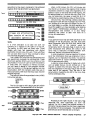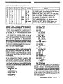
1
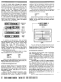
SHARP PC-l500 & RADIO SHACK PC-2
~~
o
CopyT~t
1til PCDET CCII'UTER IlEIISLETTER
MACHIl\E: LAN3lJAGE PRClGRPM'11N3
THO SHARP PC-l500
MIl Rl'DIO SHACK PC-2
PCCKET CO'f'UTERS
!
Hidden beneath the surface of pocKet computers
such as the snarp PC-1500 and Radio snacK PC-2
models Is a secret world of unique and powerful
capabilities. Alas, this world Is only open to the
initiated whO have the willirq>ess a'lCl stanina to
study a'lClleam macfline J~programmJng!
Machine language progr~ing (or I"LP as it
will freqJel1tly be referred to here) is really what
makes the entire system work. Indeed, the BASIC
language itself and all the capabilities of the
pocket computer are prograrrmed in this most
fLlkklllE!l'ltal)~
of themiclqJrocessoT.
I"LP is a .,.,.,.,Iex S<tJjecL The reason conlJUter
languages SUCt1 as BASIC were developed Is
because the average user of computers would like
to be able to use them easily. SUCh people dO not
want to be oogged down in a myriad of technical
details aoout how the computer Itself qJerates.
Details that haVe little to do with solving the
proDlem at ha'lCl. They want to be allle to ",leidy
express to the conlJUter hoW to perform a specific
set of operations in order to obtain desired
answers. The trade-off they make (f,"","ntly
without Knowing It) is one of speed Of progr..-nmlng
versus speed of conlJUter qJeration. The speed of a
conlJUter, compared to that of the tunan mind, Is
vastly "4"'rior. Allowing it to take tt.rdreds or
even tnousands of times longer than its most
efficient arrangement would require is often
urnJticeable to the casual user. ThJs~ the average
user has little regard for the fact that the PC may
take a thousa'lCl times longer to execute a progran
written in BASIC than it dOeS to perform the sane
procewre When wrttten inmachire language.
When one prograns in machine language one
has to be coo:emed with a lot of technical details.
PC-1500/JIC-2 ttachine l . . . . PTop..u.A9 (Issue 1 or 4)
These details often haVe little to do with solving
the overall problem for which the computer is
being used. If, for example, one has to perhapS deal
with 20 or 30 parameters when prograrrming a
conlJUter using a language such as BASIC, one
ml~t have to deal with 500 to 1000 pieces of
information Onstructions, storage iocations,
sequences, procedures, etc.) in order to
successfully program the same proDlem using
machine language. The reward for being able to do
this, however, might well be an overall increase in
the speed at which a specific problem could be
so)veo. This il'l1lrovement in the rate at which a
specifiC task mi~t be ac.,.,.,.,lished can often be
measured in oIOers of magnitude, such as ten, one
hundred or a thOusand of times faster!
Access to the computer at the machine level
can also open a whole new world of opportL.nities.
This is especially true if one Walts to deal at the
hardW'are level in SUCh areas as using the PC to
perform real-time control qJeratJons. Gererally
these Kinds of specialized applications carnot be
successfully-- approaChed using hl~ level
languages, such as BASIC, beCause Of speed or
physlcai interfacing restraints.
A Piece at a TIme
As .,.,.,.,lex as machine language progr~ing can
be, it Is possible to make the chore of learning hOw
to program in machine language be relatively easy
to bear. The triel< lies In breaking down the
operation of a conlJUter Into its simplest parts.
This makes each section easIer to U1derslald.
Eventually the pieces can be placed back together
as ore gains familiarity with the ftXldanental
aspects.
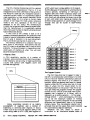
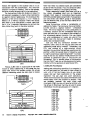
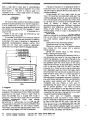
How simple can we get? How aoout defining a
cC\Il'l>Uter as consisting of two essential divisions:
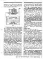
(I) a CPU a'lCl (2)merrory.
The CPU (Gentral Processing Unit) in a pocKet
COO'pUter is a microprocessor. That is, it is an
Integrated circuit that is \he heart of \he system In
the Sharp PC-lSOO \he CPU integrated circuit Is
referred to as an LHS801. It is a proprietary device
~ especially for that pocket corrj)Uter. (Since
\he Radio Shack PC-2 is simply a custom-~
version of \he Sharp PC-lSOO, I.I1less otherwise
noted In this text, operation of the PC-2 can
asstrned to be the same.) The nomenclature
LHS80l has no special signiflca-oce to anyone o\her
than the marufacturer. It Is essentially nothing
more than a part number to identify that particular
type of electronic device.
A CPU such as \he LHS80l Is .ole to dO a
nurTtler of essential operetions. But,baslcally what
is dOes is transfer Information to and from memory.
Part of what it transfers is Its O'Hn Instrl£tions.
That is, the directives that tell it what to do!
The memory elements in a COOlJUter hOld two
basic types of information. Instructions that teU
the CPU what to do and oata that is used to solve
problems. To \he I.I1lnitiated it is Imposslbie to tell
which parts of memory do what. Yoo will soon
become among the initiated.
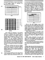
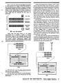
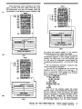
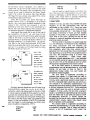
A Step at a TIme
A CPU essentially consists of a number of
registers, some electronic paths that interconnect
\hese registers, and an array of iogic-perfOrmlng
circuits that control what happens within and
between \he registers.
CPU
\~
_.
Memory essentially consists of an orderly
arrangement of registers and a method Of
addressing or selecting each register. In theory
\here could be '4l to 6S~36 registers (641<.) in the
main memory bank of a PC-lSOO, each register Of
which would have a unique address in the range 0 65~3S. (Because of \he rTaTleI In which electronic
circuits operate, rurtJerlng of Items such as
registers and cells within computers always start
",Ith zero.) Memory registers in a PC-2 have eight
cells. Each cell can asst.rn8 \he binary state of one
Dr zero. With eight cells making '4l a register, 2S6
different binary patterns or values (ranging from 0
through 255) can be stored In each memory
register.
Memory
~.ns
/'
I
I
I
I
I
I
I
I
6
••
••
••
••
,/11,\
I
I
I
I
I
I
I
I
••
••
••
••
I
I
I
I
I
I
I
I
••
••
••
••
1
I
I
I
I
I
I
I
I
0
••
••
••
••
~ress
0
Address 1
Addrtss 2
Address ,
Address '"
Address S
Adelr.s$ 6
-
Address 7
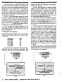
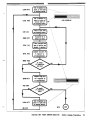
The Progril" Col.I1ter
The first thing that has to happen In order for
\he CPU to COImUlicate With memory Is for it (the
CPU) to have an "address" specifying a particular
memory register with which It is to transact Its
business. Would you believe that there Is a special
register within the CPU WhOse sole \aSK Is to Keep
track of \oIhere \he CPU shOJld obtain Its next
"cO!ITTUllcations" or InstIl£tlon? Yep! An<! it has a
very apt name: \he prognm COlrIter. The program
coo..nter in a PC-1S00 Is 16 bits "'Ide. No\oIlt ;.rst so
happens that a register of 16 binary cells can
represent '4l to 65~36 patterns -- In \he ra-ge 0
through 65~35 -- "'hich (coincidently, eh?) tums
out to be the maxlrn.rn number of memory
registers that a pocket corrj)Uter of \he type being
discussed can theoretically have In Its primary
memory banks. Thus, \he program coo..nter can in
principle hOld all the values that could translate
into valid memory register addresses.
WI1enever \he CPU neeas to obtaln a
instruction or an instIl£tion-related piece of
_
informatim from memory, it looks at the contents
Of the program counter to ascertain the
appropriate memory address.
"-'
...
Is In the process of performing other operations -such as fetChing another instruction from memory.
It also works in conjunction with other Internal
CPU registars such as the arithmetic ana logic mit
(ALU~ In this regards it is capable of performing
mathematical operations such as aaaltion,
subtraction and Boolean logic (OR, NOT, AND,
etc.~ When a series of calculations are being
performed this register can directly accurrulate
intermediate results. Hence the derivation of Its
name: acClD1lJlator.
CPU
I
I
I
I
I
I
I
I
••
••
••
••
I
I
I
I
I
I
I
I
••
••
••
••
I
I
I
I
I
I
I
I
Memory
••
••
••
••
I
I
I
I
I
I
I
I
••
••
••
••
Acldnss 0
Address 1
Address 2
Address 3
Address 4
Address
~
Address 6
Address 7
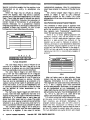
once started, the operation of the program
counter is essentially automatic. Whenever an
instructim is "fetched" from a memory location,
the value contained In the program counter is
automatically incremented to "point" to the next
memory address. There are.. however, a few
exceptions to this automatic Incrementing
sequence. A few special classes of directives can
alter the contents of the prognrn counter. can you
guess these classes? That is hardly a fair question
at this pOint; but as you will eventually learn in
detail.. the classes of instructions kOO\Nn as "jumps"
and ·calls" can change the contents of the program
counter.
How aces a computer such as the PG-1500 get
startea? Well, one of the first things that happens
when power Is applied to the unit Is that the
program counter is set to contain the aaaress in
memory where the CPU Is to begin flnalng machine
language instructions!
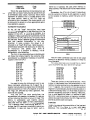
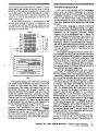
ll1e AcCI.Irulator
There is an 8-blt register In the CPU that can sort
Of be consiOered as a "jack-Of-all-traaes." This
register is able to hold Information while the CPU
CPU
One of the most frequent uses of the
accumulator (which will frequently be _revlatea
as the A register In this text) is simply to serve as a
"scratch pad." That Is, it Is simply USed to hold a
number or binary pattern while the CPU obtains
another operator. The accumulator in the PC-1500
can be loaded with a value obtained from memory
or from another CPU register.
When directed to do so; the value in the
accumulator can be aaaea or subtracted from the
value of another CPU register or a location in
memory. It can also perform logic operations with
the contents of other CPU registers or memory
locations.
Also, certain instructions can cause the
contents Of the accurrulator to be shlftea to the
right or left. This capability serves many useful
purposes. It is one way in which multiplication or
division can be implemented.
You will deal with the accurrulator frequently
when doing machine language prognrnmlng. There
will be much to learn abOut Its versatility.
Flags
FJagsare single logic cells that can assu-ne one of
two states: set or reset (the latter sometinies being
referred to as "cleared"~ The PC-1500 has five
separate flags. While each flag operates
InaepenOently, as far as the prognrnnner Is
concerned they can De vieWed as being grouped In
the five least significant bit positions Of an 8-blt
flag register. This concept Is Irr4Jortant because at
various times It will be Important to be able to save
or restore the status of all five flags at one time.
Special Instructions enable the flag register to be
rrmlpulatell as ~ entity to ~lIS1l tills
objective.
While the flags may be viewed as residing
wltIlln one register, each flag serves a specific
purpose and Is operatell Independently of the other
flags. These flags are usell to Indicate the results
of vartous operations following tile execution of
certain classes of Instructions. It will eventually
become necessary for a prospective macfllne
I~ program ner to tIloroo.q>ly Understa'lO the
purposes of eaoh flag. I-tlwever, for now a Drief
In\roWctlon to their flToCtlons will suffice.
PC
A
PROORfII COIfJER
..........1..
F.....
'/h
FI-
mathematical proceOOIes. Ma'ly M.- prograrrmers
never have occasslon to make use of tills particular
flag.
The Interllpt enaDJe flag 0 flag) Is used to
enable or disable a type of CPU inter""t
capabU1ty prOVided for tile LHS801 CPU. Most
programmers will not have to be concerned wltllits
applications.
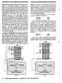
Data PoInters and GeneraJ Purpose Registers
Tne LHS801 has a whole g~ Of registers tIlat
may be useo for several purposes. WhIle not having
quite the versatility of the acamulator (in tIlat
they generally lacI< "calculating" capabilities),
never-the-Iess they come In very handy.
There are six of these Qer1eJaJ .au.znw. 8-bit
However~ they can be paired to form
registers.
ti1ree sets of 16-bit data pailltcI registers. When
serving as a data pointer the contents of the
register may be used to indicate an address In
memory where data i, to be obtained or deposited.
Note that wnen coupled together to fonn a 16-blt
register tney can hold any address in the range 0 65,535, thus lIley can point to any valid address In
memory that tne CPU Ie;; meoreUcally capable of
accessing.
H V Z I
C
10101011111111111
FLAGS REGISTER
The zero flag(Z flag) Is usea to Indicate If the
crotents of a register are zero (flag set) or If the
crotents of a register are non-zero (flag clearell~
Note the seemingly Inverse relatlonsnlp nere!
The carry flag (C flag) Is set when tIlere Is a
carry from tile most significant Olt of a register
and cleared If tIlere Is no carry dUrIng an addition
operation. ourtng suDtractlon It Is set If there is no
borrow and Clearell If there Is a borrow. The carry
flag can also be considered as ~ extension of a
register cUing ceTtain types of opeT8t1ons sucn as
SIllfts and rotates. It can also be Independently set
or clearell by special instructions so tIlat Its status
can be defined at times detennlneo by the
progldllTJer.
The IIBJF carry Flag (H flag) Is set when there Is
a cartY flom the least significant fOUT bits of a
register dUling certain types of deCimal arlttrnetlc
operations. It Is cleared when a carry does not
occur from \Ills lowel half of a byte. (The el\1lt
binary cells tIlat make '" a register are sanetlmes
referred to as a Dyts DId you I<nOW tIlat half of a
byte Is sanetlmes referred to as a nltDle? No jekel)
The overt'low Flag01 flag) Is set or reset as a
flToCtlon of the carries from the most significant
two bits of a register. It has value In certain
PC
...•
'"
YIt
_COIITEJ
Fuw:s
M:CUU.'UIlt
•
•
F
II.
~
I'-
Xl
'/':
Yl
a>U
wnen not being usea as data pointers, tI1ese
registers may be useo to temporarily store and
~Ipulate information In 8 or 16-blt format.
These legiSteTS are rather arbl trarlly referrell to as
the X, Y and U register pairs when referenceo
as 16-blt data pointers. Since each 16-0lt pair ~
also be ~ipulatell as two Independent 8-blt
groups, each may be referred to as consisting of a
high byte and a low byte. Thus the designations XH
~ XL, YH ~ YL and U; ~ UL when the 8-blt
registers are referenceo as separate entities.
It is worth noting that while a data pointer may
be lIle same 16-bit size a' tne program counter,
their functions are different. "Remember, the
program COlI1ter always tells the CPU where to
Obtain the next instfllC(ien in merrory. On \.he
other hand, a data pointer register may be used to
tell the CPU wtlere to Obtain clata from memory.
The two operations are quite dh:tinct and snould
not be confusec:!.
The Sta:k Pointer
The SIiJ{'.!<·,>1/JJtel" Is a speelal16-0it register that
has a variety Of Interesting uses. Basically, what it
does Is point to a specific address in memory whel"'!
Information Is Ul oe stored on a temporary oasis.
The stack pointer register is designed such that
eactl time it is utili Zed by an instruction, its
contents are incremented or decremented
depending on tne type of instruction oeing
performed. This operation provides a methoc1
whereby information may be pu.£l7edinto a storage
area In memory or popped out of tnat region oaCk
into Cleslgnated CPU registers.
PC
•
,.
U.
_
the most Important of Ulese Is known as the IR or
/nstJlJCtion lTi!l/ster. Ttlls register hOlds the binary
pattern representing an Instruction (fetched from
memory) While surrCXJndlng circuitry "oecodes" the
Instructim Ttlls results In Ule C1'IJ performing Ule
operation dictated.
PC
•
UH
lOt
•
Y
" ......""',,"'-$1"'" 1'OI00ER'l///h
I
rues
U
•
,
"Xl
YL
C1'IJ
F
RACS
U
AIXIIIO.lA'CR
CIUIIER
Y
STACK POINTER
SP
: : : :: Internal It.U
isten:
I'1t
CIUIIER
IICCIIIII.ArCR
_
Ul
Xl
YI.
sp
I
C1'IJ
A freq.ent use of Ule sta:k pointer Is to save
the contents of Ule program COll)ter (rernerroor
what It does?) when a program Ora"lChes from a
main sequerce of Instructions to a minor sequerce.
Ttlis process Is generally known as suoroutlnlng. By
saving the value of the PC in an area of memory
Indicated by Ule stack pointer, the CPU Is able to
eventually feSlJ'Tle operations from the point where
the subroutine was first called.
While all of this may seem complicated at this
time, oon't worry aDout the details, just grasp the
concept. The detalls of stack pointer operation will
oe presented When It Is appropriate to understand
Itlndepth.
Internal (User Tl'lrlSp8Il!nt) C1'IJ RegIsters
The registers that have IJ€en discussed are all In
some rn<n1er or anoUler accessible to the
prograrrner. That Is, by gtvlng the proper
instructions or sequerces of st.r:Il directives, Ule
contents Of trose locations can be direcUy
controlle(!.
There are a few Internal registers In the C1'IJ
that 00 a lot of WOrk that Is effectively hi<Xlen from
the view of Ule user. For Instance, Ulere are
registers that perform certain types of arithmetic
operations. As a group these COOllrise and are
generally referred to as the arittrnetlc logic unit
(I'LU for shOrt~ There are also registers that
control the overall operation of the CPU. One of
It Is Oflen worthwhUe remembering that the
Initial description of a cOfT'4)llter as consisting Of a
CPU and memory Is not Inaccurate. All a computer
really ooes Is retell an Instruction from merriory
and then e=te the directive It receives. The
beauty ana power of Ule computer comes from the
fact that It can perform a typical fetch and execute
cycle at Ule machine 1ang.a;j8 level In just a few
mUlIonths of a second. That is the case even for a
tiny haf'd-held package st.r:Il as UlePC-1SOO!
An instruction at a TIrre
Just as a cOfT'4)llter executes one Instruction at a
time, a potential machine 1ang.a;j8 progr~r
should plan on learning aDDut one Instruction at a
time. Whlle tne PC-1500 can execute several
hundred different Instructions, <lon't be
faint -hearted. Many of the InstructIons are
Identical except for the fact that they operate on a
different register. Thus, once the concepts for a
fundamental class have been learned, you will
Know how to use a Whole group or series of
particular directives.
A Treatise on MD, .. lies
i"tlemonlcs (prOl'lOlXlC8Cl "knee-mon-Ics,,) are
merrory aids. That Is Uley are a shorthan<l way Of
writing machine 1ang.a;j8 directives. They are
generally developed In SUch a way that they help
the proglamle' rernerroor what each InstructIon
does.
The novIce prograrrrner is someUmes confused
aDDut the true sIgnificance of mnemonics. It is
Important to realize that Ul a computer at the
operational level, there is no such thing as a
mnemonic. All the CPU ever sees as it processes
Instructions are the binary patterns that represent
eaCh parUcular directive. Remember, the CPU has
an Instruction "decoder" network (circuit) that
tr<rnlates each different type of pattern into a
sequence Of events to accompllsh a particular
Objective. LJnfortunately. people do not appear to
/lave sucn efflclent decoder networks In their
tleads wfJen it ames to m£Ilipul8tiry bifJiJJ"}'
pattems. HOwever, the hl.m<rl mind Is quIte adept
at handling alphanumeric patterns (probably
because that Is WIlat they are trained or
"prograrrmed" to recog1lze~ People have to
program computers. Hence, we need to nave ,.,
efflclent method of rememberIng WIlat kinds of
Instructions our computers can perform IY)d of
writing those directives down so that "",CIY) easily
tell WIlat It Is we are doing.
Mnemonics are canpletely artificial, aostract
ana arbitrary oeflnltlons Of machine longuage
Instructions. Anybody that wants to can create and
compile their own set Of rmemonlcs for any
computer. The only reason for /laving any
Standardization when It comes to using rmemonlcs
is so that other people with WI10m we converse and
communicate can readily LK10erstand WIlat It Is we
are talking abou\.
Now It happens that most CPU marufacturers
get the honOr Of prorrulgaUng a set of rmemonics
to properly represent the Instruction set Of ttleir
beloved CPU. After all, they want people to use
tnelr machines. To make life easier on prospective
custorrers, they gererally are happy to put forth an
easy \rIay to remember aU the various machine
1<rqJage Instructions that their CPU can perform.
Of course, there are always exceptions, aren't
there? When the Sharp PC-1S00 was first
Introwced, It seems that the m<nJfacturer didnot
wtnl ctY1SlIT1eFY to know flow to progRlfTl it In
macfline lW7gUBge! They
tnougnt BASIC
programming would be goad enougn for everytJoOy.
Alas, they were incorrect in their reasoning. A
large group of purcIlasers were indeed Interested In
uttltzlng the iltlle PC at Its Il"OSt powerful level.
some Of these users, In particular a group of
POCKET CO'-FUTER /lEWSLETTER rea<lers,
worked together to declpner the machine language
Instruction set that the PC was apparently capable
of performing. Tnls was done entirely Dy analyzing
the Dinary patterns stored In the RCM (read-only
memory) portions of the PC.
The principal investigator of this group, Norlin
RotJeJ; created a set of original rmemonlcs to
represent the Instructions that the group
Oiscovered. The mnemontcs tie created are the ones
used In this tex\. They are referred to herein as the
RotJerHlemanlcs.
Here is some more information that may help
you to further un<lerstand the flSlCtion of
rmemonics. If, after yw nave oesl9"l8O a macnlne
1<¥lgUage program using rmemonlcs, you plan on
having your PC execute ywr directives, you will
need
to perform a translation from the mnerronlcs
you use to the Dlnary patterns (machine cooe)
utlllzed Dy the CPU. To do this (for small programs)
you will slfTllly use a 1001<'-4' tai:>le. That taOle will
list the mnemonics yw use and the equivalent
Dinary cooes that I1"IJSt De fed to the CPU to
represent each Instruction.
Now, If you plan on going Into the "big leagues:
(SUCh !IS making your llvlng progranrnlng In
machIne 1<rqJage) then yw mlgtll eventually want
to use a special program that would help you
convert from mnemonic format to machine code.
SUch a program Is called an assembler. It Is nothing
more than a program that performs automatic
table 1001<'-4' procerures! TrouDle Is, it In Itself can
take '-4' a lot of memory ana on a small computer
such as a PC can De more of a pain to use than not
(dUe to all the shUffeling of programs in and out of
memory, etcJ sucn being the case, next thing you
know
yw are talking about using a
"cross-assemtJler." That is an assemtJler program
that works on a larger computer and produces code
for the "target" (your PC-1500) machine. Before
getting carried away with a discussion abOut sucl1
programs, let me end it Dy saying that the use of
such programs 1.'111 not be asSl.rned In this text.
Instead, I shall proceed on the Dasls t/lat small
programs, of the type Deglnnlng machine language
programmers IoIIll feel confident to tackle, 101111 be
cooverted from mnemonics to machine coae Dy the
maroal (table 1001<'-4') memoa!
Let's Add Sane of 111Is 4J
A good way to get a feel for progranrning at the
machine cooe level Is to take an In-depth 1001< at an
instruction. We are going to start with a
register-to-register addition directive. The
machine code representation for this instruction Is
the 8-DIt Dinary pattern 0 0 0 0 0 0 1 0 which can De
represented In nexadeClmal numeric sIlOrtl<nl as
the value OZ. The rmemonlc for this command is:
NXJA XL. Tnls represents a sIlOrtllanO method Of
saying: add the contents of register A (tne
accumulator) and tne contents of the 8-DIt register
XI.. (the lower naIf Of the 16-DIt register X).
Ttlere are some other things you need to know
about this directive: (1) The type of addition
performed is based on two's ccmplement Dlnary
aritnmetlc,(2) The Initial contents of tne carry flag
(C) are aaded to the least significant Dlt position at
the start of the addition process, (3) The result of
the addition process Is left In the acet.mUlator (A
register), (4) Any "overflow" from the addition
process will De reflected In the status of the carry
flag (C) at the conclusion of the operation. (5) The
status of the Z, v and H flags (along wlln the
previOUSly mentioned C flag) may be altered Dy the
results of tne operation, and (6) The original
-
contents Of register XL are rot altered by tl'ie
operation
lelolelelolol I 101
10101010101110101
XL Register
AccutUlator
(initially)
[101010101011 1111 I
AcQftIlator
L_ _ _ _ _...
carry flag
(!]
(,esuJ.t)
(result)
Gee! That is quite a list Of information to have
to Know just to effectively utilize a single machine
language instruction. All Of It Is Important, too. If
you forget just one aspect while creating a
program, you can end up with a procedure that dOeS
not yield correct results. I can tell you frcxn years
Of experience that one of tne Items many novice
programmers forget aoout when attempting to
apply this type of directive Is tile affect caused by
the Initial corditlon of the carry flag! Note that if
the carry flag is set (at a logic one state) when this
instruction is executed. . that a count of one . . . moe
added to whatever is the result of the addition. This
feature has considerable practical application. It
provides a means of performing what is commonly
Known in the field as rrultiple-precislon
arithmetic. That is a metrod whereby arittroetlc
values may be represented by the combined
contents of several registers. on tile other han<t It
can be a subtle (and vicious) trap for tne
programmer who forgets its ramifications W11en
performing simple register-to-register (often
referred to as single- precision) arithmetic. If the
status of the carry flag Is not Known (Le., reset to
the zero state) prior to executing the directive,one
can end up with an addltloo that seems to be
mysteriously off by a COtl1t of one extra The
reason this operational aspect can really throw
beglming prograrrmers Is becaUse in a cemplex
program, the status Of the carry flag may be
varying each time SUCh an Instruction Is
encountered. The net result is a program that
capriciously yields Incorrect matl'iematical
results!
All of this points out one critical factor abrut
machine language programming. It can be
extremely COITplex and one subtle mistaKe on the
part of a progra'llffiE!r can lead to errors, tl'ie cause
Of which are often difficult to detecL To get a
better appreciation of tile potential for
catastrophe, contemplate the operation of a
machine language program with, say, about 10))00
instructions. An error In the application of any one
of those cruld cause Incorrect operation Of tl'ie
system. TaKe It seriously, for indeed that is
approximately tl'ie runber Of machine language
directives In your PC-1500's BASIC ROM'
on tl'ie other hand, note tl'iet everything there Is
to Know about the operation of this Instruction can
be learned and appropriately controlled. Thus, If
every aspect is carefully considered and applied,
tl'ien there is virtually nothing that can go ""rong
(...,Iess Ire machine Itself should fail, which, shOrt
of catastrophic device failure, is an extremely rare
ocrurrence~
ExecuUon
of
Ire
f'oa:)A
XL
instruction willinvariaoly produOe Ire same result
as long as all the parameters remain Ire same each
time Ire operation Is performed.
One of the great marvels of the computer is
that once a process has been properly mOdeled
(programmed), no matter how many months or years
of development behind It, Its future use Is timeless.
It may have taken five people-years Of ""arK to
create the coding contained In tl'ie BASIC RO'1ln
tile PC-1500. However, that coding can now be
duplicated in literally millions of devices and used
by humankind for eternity (if the manufacturer
obliges~
Let us not stray too far from our course. The
sUbject at hand is learning the detailed aspects of
invOking the.ADOA XL oirective.
Another point worthy of note: Take heed Of the
fact that the carry flag acts as an addition to the
least significant bit of the registers at Ire start of
the operation HoWever, at the end of the prOCedure
It is acting as the overflow handler frcxn the rnast
siglificant bit jX)Sitlon of the accl.W'l"lJlator! Thus, in
this Instance, the carry flag appears to serve
apposite ends of a register depending on ""hen one
"looks" at the sl tuatlon. At the beginning Of the
operation, It Is serving as an adaenQ at the
rightmost bit poSition. At Ire conclusion, It Is
acting as an extension at the left enc Of the
accumulator -- effectively serving as a ninth bit
positioo.
Finally, it will be mentioned thal tile ADDAXL
instruction takes but one byte of memory to fully
specify the alrectlve. Other types of Instructions,
even variatlons of t.ne "add to the accumulator"
instruction such as this one, can take several bytes
of memory as will be outlined shortly.
Learn CIne,Learn a 8l.n;h
A nice thing aoout studying Ire machine COdes for
a particular CPU Is that once you have learned Ire
basic operation of one Instruction, you have often
learned the Key facets of a whole group of
Instructions. That Is certainly tne case with the
ACOA XL instruction. You see tnere is a whole
group of "add to the accumulator with carry"
caTman<Js:
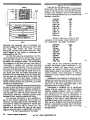
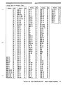
Mnermnlc
POOA 1m
POOA (U)
POOA (X)
CO<le
63
23
03
POOl'. (Y)
13
POOAnrm
POOl'. u-t
POOAlA..
POOA >0-\
POOA XL
POOA YH
POOA YL
A3
A2
22
82
02
92
12
Right there you have 11 alfferent types of
POOA Instructions. Can you figure out wIlat each
mnemonic represents?
Well, some conventions are being followed wlU1
the rmermnlcs. First of aiL the register that
follows the POOA part of the mnemonic Is al..,ays
being aaaea to the A register. ..,itn the result being
left In the accumulator. The register being ..,orkea
..,Ith is left uncnanged by tne addition operation.
The symbOl ...,... assoc::lated witn a mnemonic is a
notation thet signifies an "Immediate" piece Of
Information. AA lmmer1iate piece of data Is one
tnat Immediately follo..,s the opcode byte. ThUs tne
containing a value that will be usOO as an operand.
In tnls case the operand ..,111 be aaaea to the
contents of the accLKTIUlator.
AA NJDA rn """""Ic followoo by a 16-blt
register designation enclose<] In parenthesis, sum
as POOA(U) means thet the speclflOO register Is to
be used as a data pointer. That means tnat the
address contained In the 16-blt register will be tne
address In memory from wIllch the operand ..,11\ be
taken. In other woras, register U (in tnls case)
points to the memory address I.oIhere the actual
data byte Is located. Note tnat there Is an ADDA
Instruction for use wlm each Of the three (U, X and
Y) 16-bl t data pointer registers. Also note thet the
Instruction itself only requires one byte of
memory. The operand thet Is polntoo to by the
appropriate data pointer register can be any
location In memory. In many applications a
separate area will be reserved or established In
memory to serve as a data storage area The data
pointer will then be set up (prior to execution of the
ADDA command) to Identify the value thet Is to be
used in the addition operation.
-
mnemonic AOOA #nn indicates tnat ",natever
value is in the byte tnat Immedlately follows the
to the
acClIlUlator. If the hexadeCimal value 08 fo!lowoo
the opcode, tnen 08 woula be aode<l to the current
contents of tne accumulator. Note that this
particular instruction thuS requires two bytes of
memory in order to be fully specified. The cOCle 63,
indicating tne type of Instruction to be performed~
rrust be immediately followOO by a secord byte
opcoae (63 In tnis case) ..,111 be _
can you deWce the format of the directive
signified by the mnemonic MXJA rrnn? SUre! It
means tMt the OPCOde Is followoo by a 4-dlglt
(hexadeCimal) address. The contents of thet
memory address will contain the value !nat Is to be
added to the 8CCI.ffl.JIator. ~te thet now the
instruction uses three Oytes of melTXlfY In order to
be completely specified. one byte for tne opcode
and two to identify tne memory address !nat
contains the data Oyte.
Perhaps mis Is a good place to delve Into
thoroughly \.f1der.tancIlng !lOW many bytes of
memory a particular type of instruction Is said to
require. The key here is 10 realize that the program
counter's job Is to identify wnere the next opcoae
to be executed Is locatea In memory. If an
instruction sucn as ADOA (U) Is executea, then the
program cOlXlter (PC) Is merely Incremented once
10 point 10 the next consecutive memory location.
This is becauSe the ADOA (U) directive oniy uses
one byte of memory In \oIIllcn the actual opcOOe
itself Is stored.
However.. when an instruction such as AODA
AOOA Instructions discusSed all took a data byte
from a location In memory.
M Grdered structure
While this text will not dWell on "nardware"
aspects of CPU operation, from tlme-to-time I
may point oot features that are relatea to the
Intemal circuit design. This will De done for the
purpose of prov!d!ng Interesting and usefu!
mater!a! that may De of value to some maChine
#nn is processed, the PC must be incremented
language programmers.
twice. Once to <r1vance over the opeoae <rd once
to go Deyond the irTlTlediate byte of data that must
De proviaea after the opcOOe!
AM, the Instruction AOOA rrm will cause the
PC to De incrementea three times. once for the
opeode, twice for the two bytes following it that
hOla the 4-dlgit hexadecimal address where the
data value Is located.
For instance, let's spend a few moments
examining the machine cOOes that are used to
represent the AOOA commands. The cO<les are
shOWn !n hexac1eClmal notation. The two
hexadecimal digits are easlly expanded Into two
adjacent groups of four binary bits. Thus, the
hexadecimal coae for the ADOA #nn Instruction,
B3, st<rds for the binary pattern: 101100 11.lt is
interest!ng to note that all the AOOA directives
associatea with intra-CPU register aaaltions eM
with the t'exadecimal d!git 2 \oIIlUe all of those that
involve data bytes stored in memory ena with the
digit 3. Yoo can also OIlSeTVe that the most
significant hexadecimal d!git simllarly exnibits
interesting structures. For Inst<rce, the most
sil}:lificant digit for AOOA (X) Is 0, \oIIllle for NXJA
(Y)it Is 1 <rd for ADOA{U) It is 2. LooK, \oO,atnow
the most significant digit haS a distinct pattern
amongst the AOOA XH ana XL, YH and YL ana UH
and UL cOdes. When expanaed to a binary
representation it is clear that the most significant
bit !n the opcOOe is being used to select the high
order register of eacn register-pair.
This !nformatlon ml~t seem like trivia 10
Deglmlng programmers, but it can have practical
application as you ga!n coding experience. II you
haVe ever had occassion to watch a seasoned
machine language programmer at wOrk (one with
several years Of concentrated practice) you may
have been amazed to notice that the person
apparently knew now to directly translate machine
cOOe from, say, a raw
hexadeclmally-coded
memory dump. One Important wayan experienced
programmer develops this SkU! Is by learning the
significance Of particular bit-patterns <rd the use
of inalvidual bits within those patterns.
For instance, there are only two other types of
PC-lS00 M.. instructions that end with the
heXadecimal digit 2. One of these other types
always has the most significant digit In the
hexadecimal range C through F. The other uses 4,5
or 6 as the most significant digit. Knowing this (by
heart!) yoo can instantly classify any machine COde
ending with a 2! Woold yoo be surprised to know
that the group that has 4, 5 1r<l 6 In the most
sign!flcant digit positions involves the X, Y <rd U
registers In that order? Not if yoo noticed that the
CPU
In surmary, the program counter must
automatically De <r1v<l1CeO so that it identifies the
start of the next instroction t.tIat 1s to be executed.
The nurmer of bytes that it must De aavanced over
for each type of instruction is what 'He are
referring to \oIIlen we say a directive is a one-, twoor three-byte directive. (WIllie most instructions
executed by the LH5801 only require 1 10 3 bytes,
there are a few that need even more. Those will De
Introduced In due course.)
Finally there is a group of AOOA instructions
of the type with \oIIlich you are thOroughly familiar:
the group that adds the contents Of an 8-bit CPU
register (UH, UL, XH, XL, YH or YL) to the
ac:cuT<Jlalor. Note that this latter group consists
of data operations that are "Intra-<:PU." That is,
the addition operation taKes place amongst
registers within the CPU Itself. The other types of
i>DOA group had the roost significant digit
advancing from 0 to 2 In the same order for
.
registers X, Y and U!
I am not going to recoomend that a begmner
proceed to put mucI1 effort Into memorizing this
type Of information. I am, ho",ever, pointing out
hOw 1t can be Clone so that you will be aware ttlat
the CPU is a logical device, it ",as designed by a
numan designer ...ro developed logical patterns to
control its operation, and there is nothing magic
about me macnlne. As you gain familiarity ",Ith a
particular CPU you can start to casually look for
suCh recurring patterns and use the Information for
what it is worth. If you oecane a profeSSIOnal
macIline language prograrrmer, it can be worth a
lot Of time. However, it Is not a necessary sKill. You
can always looK up the meaning of any machine
cDOe in a suitable machine CDOe table or better yet,
use a computer program known as a disassembler.
More about tnat later.
AOO wltInlt the carry
AS you ml(1lt Imagine, there are times when a
prograrrmer may want to perform addltJon
operations ",Ilhout naving to be concerned WIth the
status of the C nag at the start of the procedure. (In
other wo/lls, without having to be bothered "'ith
seeing that the carry nag has been cleared.) The
LH5801 CPU has a group of instn.ctions that
provides tnts capability. but it Is not as
comprenenslve as the previously desCribed !'aJA
category. In fact- it is restricted to coornands that
add an Immediate data value to the contents of a
location in memory. instead of the aco..mJIator.
'---:t!J:
....
--
PC
f
A
...
...
'"
IQ.
YL
VI<
SP
..
addition Is performed using two's complerrent
notation, (2) The initial contents of the carry flag
are ignored at the beginning of the alldltlon
process, (3) The result of the addition operation Is
left in the memory location referenced oy the
instn.ctlon. (4) The status of the carry flag wm be
determined by the result of the addition operation.
It is set If there is an overflow, cleared otherwise.
(5) The status of the Z. V and H flags may also be
affected oy the results of the procedure.
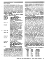
The first three Instructions In this group are
tWO-byte directives. one byte representing the
opcoae, the second the value that Is to be added to
the specified location in memory. Note that the
16-Oit registers U, X or Y must contain the address
of the byte in memory to wnien the immediate data
is to be 8dded.
Cony ....
."""'.
leleleleleleiliel .,..
-..,..
lelelilele'I'I'el
(Initially)
Ie'ele'elelliliel
['--- - - -.... I!I
The set has the following m erronics and machine
COdes:
Code
6F
IIF
SF
A
...
,
...
XlI
IQ.
VII
YL
PC
SP
EF
There are a ru:rtler of points yoo rrust knO", In
order to properly utilize these directives: (1) The
10
- . . l _ Proar-"
.....1"" 'M3 PO:Jll
COIPUTtJt IIElISlfllE1t
The last directive, I\OI'C rtn'l 1m Is an
oXlOTple Of a directive that ...1II cause the program
COlIlter to be adIIanCed by a COtrlt of f()(ff...nen It
IS executed. 01ce for the opcode, t... lce for the
16-blt meroory address In the next t ...o bytes, and a
fourth tlrre for the Irrrnedlate data byte!
""te the machine Code pattem The lo...er
nibble is F for the entire class of Instructions. The
higher nllJble goes from 4 to 5 to 6 to sl\Jllfy use of
the X, Y and U registers respectively.
This type of instrUCtion can be partiCUlarly
valuable ...nen it Is desired to adVance an addreSS
pointer that is being stored in meroory. ThiS is
especially true ...nen one Is In a situation Where It
ml9'lt be beneficial not to haVe to alter the
contents of the accurrulator.
~
You will Lnblbtably not be swprtsed to learn that
the LH5801 CPU Is able to perform subtractlm In
lact, it has an entire group of directives Similar In
structure to that of the - _ with carry" group that
has already been dlsrussed. Here are the
In .. , ooics and machine CodeS used to represent
these subtraction directives:
M-lemonIC
'-"
Code
B1
5I..8A1m
Sl8A (U)
Sl8A(X)
Sl8A (y)
Sl8A.......
Sl8A LH
Sl8A Lt.
Sl8A XH
Sl8A XI..
Sl8A YH
Sl8A YL
21
01
11
AI
All
20
80
III
90
10
All of the subtraction dlrectives take place
between the accurrulator and a speclfle<! register
or mermry loeatlm Here are the Important things
to i<rlOW abOUt these !llrecllves: (1) The arltNnetlc
convention utlllzed Is known as two's complement
notatlm (2) The complement of the carry flag Is
consI<!ere<! as a bOrrow. (3) The contents of the
[I]
carry H ..
r::1.~I.~I,::::.r.;I.~lo~I'::::or:!I'T.I.~1
II.
liiolololoiliolol
=!:~
['010'0'010101110'
'- - - - -.... [I]
1IOOi-
specIfied register or mermry location are al ...ays
subtracted Irtm the contents of the accurrulator.
(4) The result Is left In the accurrulator. (5) The
original register or mermry location value Is left
.. ochanged. (6) My "lJn<lerflo.... Caused by the
subtraction process ...111 be reflected In the status
of the carry flag at the em of the operation. (7) The
status of the Z, V and H flags may be altered by the
operatim
~
As was the case with the additioo directives, the
slbtraction instructions take one.. two or three
bytes depen!ling on the at1t1resslng involveO. The
group of Subtraction Instructions Iisteo represeno.
four differen t types Of aCldressing mode$.
Those such as SUlA UH and SUlA u.. utlllze
...ret is known as /npJ/ec/ addressing. That Is, the
opcode itself specifies the registers or locations
that are affected by the qJelatlon. The
hexadecimal opcode 20 (""Iell Is 0 0 1 0 0 0 0 0 In
binary) tells the CPU everything it has to i<rlOW In
or<!er to perform the directive. When It <!elects
that pattern, It "l<nows" that It Is to perla"" a
subtraction operation using the OCC\.ITl.Ilator and
the 8-bit UL register. In a like fashl""- the pattern
1 0 1 0 0 0 0 0 (AD hexadecimal) tells the CPU to
perform the SUbtracUon bet...een the 8-blt UH
register and the accumulator. These types 01
dlrecUves only use one byte of memory SIrQ! the
addressing informaUon (related to wnat registers
will be affected) are Inherent ...ithin the actual
machine axle. In fact, this rro!le of addressing Is
sometimes also refene<! to as ime1'E!flt or "'gister
addressing.
The dlrecUve SUlA 1m Is an eXMl'le of
inmediate addresSing. The byte that Immeotately
fall"", the opcode is the location \hat Is to be
sLbtracted from the acctn"!Jlator. TIlls alrectlve
requires two bytes of merrory. O'le for the opcode,
the other to rold the data \hat is to be sLbtracted.
The Instn.ctions SU8A (U~ SL.eA (X), SL.eA (Y)
all represent exarlllies of what Is often referred to
as ~istBr indirect adttresslng. TIlls Is because tne
contents of the 16--bit register q, X or Y ooids an
_ress of a memory location where the actual
data \hat Is to be sLbtracted IS storea. ""te \hat
the U, X or Y registers themselves 00 not rold the
data, rather they point to the data location.
..... , .
.----
,,
,,
""te \hat these two adttress bytes are considered
as part of the instn..,tion. mus, this directive t<i<.es
three bytes of merrory to be properly defined.
Tnese BdJJ=ing rnoO!!s (..-.:l there will be a
few others Intro<l.ced later) are 00 IlT'4JOrtoot
concept. Most types of Instn.ctions have several
alfferent possible adttresslng modes. If yw go bacK
now and review the N:£JA grlJl..4) of instructions
y"" can observe \hat It has the exact SMte set Of
_ressing modes.
Some Instn.ctions utlllze a combination of
adttressing modes. The previOCJSly alSCUSSed PDN::
(U) 8m utilizes a register indirect - /tm'IBO/ata
mode. The 16-bit register (U In thi s case) points to
a merrory location ..-.:l the Irrvnedlate data byte
t"Olds the data that is to be added to the contents of
the referenced memory locatlon. Can y"" figure
OCJ\ what combination of modes are used In the
AONC nnnn 1m instn.ctlon? Right! It combines
direct and immediate modeS.
Can yw find any comectlon between the
macnlne cooes USed (In the opcooe byte) ana the
adttressing mode being IrMlked? Remember, ttle
CPU was created by a logic-oriented ci rcuit
oosigrer. Do Y"" tnlri< that perhaps a particular bit
position within the opcode byte is frequently used
to signify a particular adoresslng mode? You might
Keep an eye wt for oooress-mode patterns (In the
opcodes) as additional types Of instructions are
intrOCilced. This is afI(lttler piece of information
CPU
Finally, SU8A nnnn Is illustrative of the mode
kno...., as direct adttressing. In tnls mode, the two
bytes \hat follow the opcode contain the actual
address Indicating Where the data byte IS stored.
....,.
that the ·pro's· 1_ for as they become intimately
familiar with the operation of a particular CPU.
t.~ the I'<:o.m.IIator
I'<IdIng ana sLbtracting q:.ootltles in a computer Is
all well ana good, bUt Y"" need to have values to
work witn in the first place. How 110 you obtain
values and get them positioned In the proper
registers? You use Joad and store directives.
These are instnx::tions that cause information to be
moved about from one location to another. They
are probably arncrgst the roost often USed
cCllTYTl<nls. Rigot now we will become familiar wltn
the g""4' of directives \hat may be used to place
Information Into the acctn"!Jlator or A register:
M1emonic
Code
LOA 8m
LOA (U)
LOA (Xl
LOA (y)
CPU
Ei5
25
Il>
15
LOA nnnn
LOA ~
LOA LL
LOA XH
I'{j
LOA XL
LOA YH
04
94
LOA YL
14
f'oA
24
84
•
Here Is what you need to koow about this group
of InstrucUons: (1) A "copy. of the InformaUon in
the specified memory locaUon or register is always
transferred (loaded) into the accurrulator. (2) TIle
status Of the Z (zero) flag will reflect whether or
not the value transferred was equal to zero. (3) TIle
other flags are not affected by this type of
operation.
~
B
E
Zero flag
6 lelelelelelelelel
~
Ixlxlxlxlxlxlxlxl -...1_
(Initially)
~ ~.lel.I.I.I.I.I.1
~l
I]]
-.(result)
Zero flag
(rewlt)
)( • Does not malteI!
-
There, that was easy wasn't It? All these
instructions do is provide a means of moving
information about in the computer system. Note
that you can transfer data from the CPU regIsters
and (using several addressing modes) from
locations in memory. ThIs particular g~ always
places the data into the acru:nulator.
L;
1
1 1 1 1 1 1 1 1-
/
~
¥
PC
•
,.
which all the bits are cleared to zero) haS mary
practical applications. It is often used to denOte
the end of data in lookup tables, to mark the end of
a string of stored text, and so forth. So, being able
ta easily detect the presence Of a zero byte when it
is first loaded into a location.. can have
considerable practical programming value. The
LH58D1 designers knew this and thus permitted the
zero flag to be affected ~y this operation, whUe
protecting all other flags.
The load directives are used so extensively in
machine language programming that it is convnon
to provide supplemental types of instructions. For
instance, the CPU used in the Sharp PC-1500 has
the following special load directives:
Code
65
45
55
67
47
57
XH
X
Y
STD. POUlTER
Xl
....ry
Yl
: inwniJ' M.U----.:;;rstus : ::
You might also want to take note of the fact
that only one CPU flag Is affected by this type of
directive: the zero (Z) flag.
Can you think of any reasons why the deSI!P'TS
allowed only this flag to be affected by the load
1
"7
F
Ul
:::
load operations? Because, as will be illustrated
later, being able to detect a "zero byte" (a byte in
'~m
U
$I'
with carry instructions would be worthless dUring
such operations.
But why let even the zero flag be influenced by
lOAI (U)
LDAI (Xl
LDAl (y)
LOAD (U)
LOAD (Xl
LOADM
UH
VIi
'--"
PC=PC·2
1 1 1 1 1 1 1 1
Because these numbers take more than one byte in
which to be stored, they have to be proceSSed in
byte-sized sections. If a load directive interfered
with the status of. say, the carry flag. then the add
Mnemonic
10 I 1 Q 1
/
There are several good reasons. One is that
some of the other flags, such as the carry, need to
be maintained When multiple-precIsion arithmetic
Is being performed. (That Is arithmetic Where the
numbers being manipulated are stored in two or
more bytes, yet are considered as one value.)
/
~c
:
:~
1
1
u;u.,-
~
Yl
STACK
ill
~
,
<
operations?
Copyright 1983 POOKET COIPUTER NEUSlETTEI
nachine l ...... Prograwdng
13
These are known as load anct irx:rement CI1I1
loat1 ana t1ecmment atrectlves. They transfer a
byte from the memory location pointed to by the
contents of the 16-01t registers (U, X or Y) into the
accunulator and tIIen I/Iey automatically
increment Of t1ecrement tile pointer register by a
ClJU7t or one.' These powerfullnstTl£tloos are most
useful..men It is desirable to sequentially process a
wholeOIOCl< of memory.
only the Z (zero) flag can De affected by these
directives, in exactly the s~ rn<rrler as for the
LOA (U) instruction. That Is, it Is cleared if the byte
transferred Is non-zero a'1d set If It Is zero. Notice
that the Increment or decrement of the pointer
register Ooes not affect the flags. /t is l/7e byte
being tl8l7sferred that controls the status of the Z
flag when any of this group Is executed.
All of the load instructions discussed so far
have been deSigned to transfer data Into the
acclJ:Tlulator. But, now abOut getting data Into the
other CPU registers?
'
LoadinJ other Cf'IJ Registers
Each half of the 16-blt regi sters U, x a'1d Y can De
loaded with irrmedlate data by the following load
instru::;:tioos:
Mnemonic
I.1lU-l
U:U ..
coae
~
~
68
6A
LDXH 1m
LDXL 1m
LDYH 1m
LDYL 1m
48
'IA
58
SA
One important difference between this group of
directives and the previously described load
commands that dealt with the accu:nulator Is that
tD?e of I/Ie flags are altered by these transfers,
not even the zero flag.
The fact that each half of the 16-bit pointer
registers can De loaded with a byte has many
practical applications. FreqJenUy these registers
are used as tE!fl1lOrary storage locations within the
CPU. Being able to treat these registers as
consisting of two indepel KHlt bytes (..men it is
deslree! by the prognnrner) means that more data
can De reaatly accessed within the Cf'IJ.
on the other hand, you !ruSt rememDer that if
you want to set up a 16- bit register so that it
contains a rnemJry aJetress, then you roost use a
sequerce of two load immediate instructions. Ot'le
to load the most significant half (Ll-l, XH or YH)
a'1d the other to load the least significant half (LI..,
XLorYL~
It would have been theoretically possible for
the CPU designer to have provided a load
immediate instTl..lClion that loaded all 16 bits of the
data pointer registers at one time. The advantage
of opting for the 8-blt loads is flexibility. The
tracie-off Is that It taKes two loadS to completely
define an address. (However, as you wl11leam later,
this is not as serious a trade-off as It might
initially <wear. In practical progranming
situations It turns out that the most significant
portion of an address _ s not haVe to De changeO
as often as the least sIgnificant portion. Ttm,
ITaly times, the address in a data pointer register
can De altered to the desIred value just by changtng
one byte.)
There is, In fact, a 16-bit load immediate
directive provided in the Instruction set of the Cf'IJ
being discussed. It ts used to toad the stacK pointer
with a """1'lete 16-blt address.
~~~!!~~~:~I~:':J~CI:C~
A ~ IICQIUATca
~
lOt
m
SP
Cf'IJ
f
~
U
1-____..X-I-___-I1Cl
n
I
I
I
I
•••
000 I I I
;:::; intm..'l '1i.1.i . , 'siUs
Cf'IJ
I
::'
Mlermnic
~rrR1
CO!le
M
This Is the mlJ' directive In tile instruction set
YIT1ere the two Oytes following tile opcode Datil act
as Irrrnedlate data values. Normally tIlese values
represent an address tIlat Is loaded direcUy Into
the Stacl< pointer. None of the CPU nags are
affected oy tills Command. (,Tile stacl< pointer wlll
oe discussed In detail at a rmre appropriate polnL
Have patience, please.)
marker as is typically tile case when memory Is
oeing scanned. TIle distinction will oe made clearer
later.
Rernemoer, tile STA (U), (X) and (Y) directives
use the contents of those 16-bit registers to point
to the location In memory YIT1ere the Oyte wlll oe
saved.
storing the Accurulator
SO far, all tile "load" Instructions have oeen
transferring Information in one direction: Into tile
CK;ClI11Jlator or fran a locaUon In memory to a
register In tile CPU. It IoIOOld oe a pretty useless
computer If data COUld only oe transferred into tile
accumulator or CPU and not out Of course, that Is
not tile case. TIlere Is another group of instructions
that C<Vl transfer Information in tile otller
direction In some systems, till s gl'Ol{l Is s till
referred to as "load" directives. Here, hOwever, to
differentiate Oetween tile directions of data flo""
an Instruction tIlat passes data FJrm tile
accumulator to a location In memory, ",111 oe
deSignated a ,\'[llI8 dIrective.
The first of the store directives to oediSCUSSed
are those that slfTllly transfer tile contents of tile
accumulator to a location In memory or to an 8-0it
register within the CPl),
Mnemonic
STA (OJ
STA (Xl
STA (y)
STA rrR1
STA l.H
STA U.
STAXH
STA XL
CO!le
2E
IE
IE
I'£.
28
2A
08
OA
STA YH
18
STA YL
lA
You need to know tile following in order to use
these commands effectively: (1) A copy of tile A
register (acCU'nUlator) is placed into tne ir<llcated
memory location or 8-0it CPU register. (2) f\IoI1e Of
tile flags are affected by these operations. Not
even tile zero (Z) flag.
Ttm, the CPU C<Vl store results from tile
acGlJTl.Ilator into mermry or cnJther CPU register
withOUt altering tile status of any of its flags. Tnis
ability to accomplish such transfers witllOUt
altering tile flags is useful In many circumstances.
Note that now not even tile Z flag Is sacrificed.
Tnis is Decause when =lfI.Icting tables or text
strings, tile CPU C<Vl insert a zero Oyte to serve as a
terminator. It does not have to detect SUCh a
CPU
TIle STA mm COIl"iTIa"d uses tne 16-0it value
(nmn) as an absolute memory address In Which to
store trIe data.
The store directives also inClude the so-called
auto-increment and auh'··decremen! groups:
M1emonic
STAr (OJ
STAr (Xl
STAr (y)
STAD (I.J)
STAD (Xl
STAD (y)
CO!le
61
41
51
63
43
53
These are similar to the load t1irectives. After
a oyte Is transferred from the acctmJlator to tne
memory location pointed to Oy tne address In tt., U,
x or Y register~ the contents of the aata pointer
register Is automatically incremented (by one) or it
is decremented (Oy one~ It Is thUS ready to point to
tile next sequential location in memory. Naturally,
this is quite _
icial when It is deSired to pact<
data into a contiru:x.rs blOCk of memory. l-fO'.Nevec
unlike the load instructions, the CPU flags are not
altered by these store commands.
In_OJ(
Finally, to wrap up the presentation of the load_
store Ins tructioos~ there is a real Wfliz-bang
directive. This CorTYM"<l aces the equivalent Of
CopyriWit tM' PlDET COlMER tEUSl.ETTER
ftachine L~ hoor...nng
15
botll a load <rid a store plus It autoolatlcally
increments two data pointer registers' It is a real
block-buster - - <rid tIlat is exactly wtoat it is
interned to ao - - rIDve large blOCkS of memory
quickly and coovenlently.
cooe
Mnemonic
STI
CXXYJ
FS
Oyte of data stored at tne memory location
pointed to by the contents of 16-01t CPU register X
is first loaded tnto an intemaJ CPU register. It is
tI1en stored Into tile memory location polnted to Oy
tile contents Of the 16-bit CPU register Y. Next,
the contents of both X <rid Yare adV<Y1Ced Oy a
count of one.
None of the CPU flags are affected by the
operation of this instruction.
It Is a super Instruction to use wnen you need to
move blOCks of data from one location in memory
to '""'ther! This type of directive Is Indicative of
adv<Y1Ced microprocessor deSIg1S. Earlier CPU
chips did not have such powerful operations
combined Into a single macnlne language opcode.
The
,
,
,
,~.
"_I,
,.
F
A
x~;
V'
,.,
1'1
I
1
~
Vl
STACk
fl..
CPU
Only a small fraction of the commands that are
available In the repertoire of the LH5801 heve been
presented at this poinl There Is much more to
learn. But perhaps now is a good time to get a
glimpse at what the future lookS like for a machine
language programmer. More t~ enough
instructions have been explained so that we Carl
demonstrate a rudimentary, out actual, program.
The purpose at tIlis point is to build confidence <rid
provide some feecJt)aCk for the serious student.
Take heart, what you are learning really work.s. You
can make things happen with this information!
"chine ·l ...... Proar..nna
CIependS on yrur objectives. Sometimes. . there Is
really no such thing as a best way. There are,
instead, simply a nost Of ways to accomplish the
scrne end result.
Before reading further, you might just want to
take a few mirutes to write down scme Of the ways
tnat you can think of to accomplish the goal: add
two simple nurntJers together and store tIlem in
memory.
Did you tIlink of tile following method?
(1) Load one value Into the A register.
(2) Store the contents of tile A register (which
now contains the first value) into a specific
memory location.
(3) Add the second value to that memory
location, leaving the result there .
One reason for ChOosing tnis methOd is tnat it Is
not affected by the status of the carry flag at the
Instructions thet add something to tile accW1lJlatof
are dependent upon the initial status of tile carry
nag? How do you know, at ..,y given point, what tile
status of the carry flag is (or will be)? If you don't
Know wtoat it is, should you be using .., instruction
tnat is deperdent upon its status? (Actually, there
are instructions that can Oe used to place the carry
flag In a known state. AnO, It Is often possible to
logically control the state of the flag at a
particular point in a program. However, if you aon't
know wtoat tnose methods are, tnen you had better
be careful wnen dealing wltll "add witll carry"
commanos!) DlO you chOOSe a safe way of
accomplishing the given task or would you nave
on I..IflSUre grOtlldS? YOll were on f.K?SU!e
grot.nds if ytJIJ elected to use ErlY adO witll cany
been
A P1tg1t111
16
far? There are quite a few1 believe me. In fact~ that
1s one of the joys of working at the machine level.
There are usual! y a variety of ways of
accomplishing any given task. The "best" way often
start of the operation. 00 you recall that all of t.tte
Ipc
I:
I;
The goal at this point Is to develop a series of
instructions tIlat will accorllllish tile following:
Add one rurlJer to ,"",tiler <rid slDre tile result in a
location in memory.
Simple enough, ell? How ITaly ways do you
tnlnk tnat could be accompllsned using just the
machine language directives you nave learned so
directive andytJIJ did not specifically devise a way
Of Insuring tllat tile Cimy flag was set to a known
statepriOf topel'fonnlng tI18 adtfitiml
The flrst rule of machine langJage
programming is tnat you nave to kno", wtoat Is
going on. Guessing or hoping tIlat conditions will be
tnis way or tIlat way will not work. If you can't be
sure about the status of sorrething, tI1en you had
better design tIlings so thet you end up kno",fng the
status. If you cannot logically figure out a way Of
accomplishing this, then the machine cannot do It
either. (You see, ytJIJreally elli'the bosS.)
CcIoJti"'t 1981 PUJ:ET UJUIUTER tEUSLETTER
-
Three directives ,"auld accompliSh tile stated
goal: LOA ~, STA 1TT11, ACN:; ITT11 #Tn LoaCI
tile accurulator with tile first runber. Store tile
accurulator in tile desired merrory locatim Add
'eel
'ee2
'ee}
,ee'
-ry
,aco
..
I
78C1
'Be2
'Be}
''''''
7SC7
...
..
'8C9
O}
,
EF
..
00
I
,...
"...
00
'8C8
..,.
00
'BeO
EF
.,
....
I
"08
00
,,Be,
''''''
I
"e>
78
78C.
-'.
18(0
CPU
r-........
=
,ac2
,ac}
CPU
-ry
~~~~iP.:j
(no carry) tile secood runDer to the memory
location Where the first ntrnber was storect
If tile nuntJers to be added were 3 and 4 and tile
hexadeCimal address Of \he storage locatiOO in
memory was 7800, here Is hOw \he mactline code
for this series of instructloos "OIJIO appear (in
hexaoecimal notatlon~ B5 03 PC 78 DO EF 78 DO
04.
The accompanying pictorials illustrate eacn
step of tile program's operation.
You can try this program out for yourself by
loading it into a PC-1500 or PC-2. one ,"ay to dO
this is to use BASIC POKE statements. Here is a
BASIC program that will loaa and \hen execute
those mactline 1<YlgUage directives:
lO:JIO(E a78CO, 1!115
,803, ME, a78, a
00, lIEF, 1176, I!OO
, &04, a9rA
2O:CI\I..1. 1Io78CO
3O:PRINT Pffl( a78
00
lac.
,8C>
'806
18C7
78es
78C9
40:ENJ
-
CPU
Line 10 of this progra-n places \he actual
machine codes (using hexaoecimal notatloo) into
tile PC's merrory. These Instructioos ale being
stored in \he portioo of merrory normally used to
hold tile BASIC variable f>$, starting at tile
hexaoeclmal address 6o.78C0. The values following
the faur-dIglt address are tile actual mactllne
codes for the program in hexadecimal format. (The
last byte in line 10, &9A, is the Code for a machine
language directive that will cause the machine
language program to be exited back to BASIC.)
Line 20 causes the machine language codes to
be executed starting at hexadecimal address 7BCO
(where the program was stored~ After executing
those machine code directives" control returns to
the BASIC program.
Line 30 causes the PC to display the contents of
the memory location having the hexadecimal
address 7800. This is the first byte of the area In
which the BASIC variable B$ is normally stored.
The machine language program uses this location
to store the first number (from the accurrulator~ It
is also the location where the ADNC instruction
takes actioo and leaves the results of the addition
(without carry) operation.
Line 40 denotes the end of the BASIC code.
Executing this BASIC program by placing the
PC in the RUN mode and executing GOTO 10 or
RUN should result in the value 7 being displayed.
00 you understand everything that is gcing on
at this point? Does everything in the deSCriptive
pictorials that portrays the operation of this
machine language procedure make sense? If not.,
now is a good time to review the earlier parts of
this text.
By the way, attempting to examine the
operation of machine language routines by using
PEEK and POKE directives is a very slow and
tedious method. A far better tool to use is a
machine language monitor program. This is a
special program designed to facilitate working at
the machine code leveL If you plan to make a
serious study of this diSCipline" 1 strongly
recommend that you obtain a copy of the
LoaderlMnltorlDlsassembler package sold by the
POCKET Ga'fl.l7ER I\EWSLET7ER This is a
powerful tool that makes it easy to place machine
codes into memory.. examine ttle contents of
-memor.y... execute machine language routines.. and
so fortti;--m--a--dHecLrnode.. without having to
translate through PEEK ana-POKE directives. The
disassembler program which Is part of this package
utilizes the Rober fvfnemonics wnich are used in
this text. It Is able to translate machine codes
directly into these mnemonics. Hence, it is highly
useful for verifying that machine language
routines have been properly loaded into memory as
well as for use in exploring "uncharted" areas of
memory (such as ROMs~ The loader part of this
package makes it easy to put together sections of a
machine language program Plus, the package
provides a convenient means of saving and
restoring machine code programs by using a
cassette recorder. No serious M..P student sto..Ild
be without such a tooL
18
nech:ine l~ Ptogr..nno
CGpyrltbt 1'"
Is learning to program in machine language
worth all the trouble? Not for everybody. It
dePends on what you want to end up being able to
do. You now can probably begin to see that dealing
at the machine level greatly complicates matters
from the programmer's view. It tOOk nine bytes of
memory storage just to specify the adding together
of two tiny mmtJers. Even with such a simple task..
one had to be concerned with the use of the carry
flag. The work is greatly cOfTlJOUl1ded when one has
to start dealing with larger values or non-integer
quantities.
But, you can probably also gather that the
degree of control at this level is fantastic. You are
able to dictate every aspect of the machine's
operation. Streamlining the flow of operations to
accompliSh a specific job is just one noticeable
benefit. Speed of operation is another. Do you
realize that those three instructions used to add
together two simple numbers can be performed in
about 25 millionths of a second? You could string
together some 40,000 similar sequences and still
have them all performed in less than a second!
If you still want to hang in there and learn more
about the subject, then read on. It is time to
describe some of the logical operations that the
LH5801 CPU can perform.
The Logical PN)
The next few classes of instructions that will be
discussed are those known as Boolean logic
operations. In the LH5801 these mathematical
operations are always performed on the contents of
the accumulator or on the contents of a location in
memory.
The ability to perform these types of logic
operations are valuable in many applications.
Indeed, they give the computer the ability to
dUplicate the type of electronic logic found in
modem electronic digital circuitry.
These logic operations are always performed on
a bit-by-bit basis between the accumulator (or a
memory register) and the operand byte. The results
of the operation are stored in the accumulator (or
memory register~ Furthermore, the status of the Z
(zero) flag will be affected by the results of the
logic operation. Thus, these types of directives,
among others, ultimately provide the computer
with a means of modifying its own behavior
dependjng on j(s fjndjngs as it examines data
The first group of Boolean logic operations to
be presented are those that perform a logicali>NJ
operation between the accurrulator (A register)
and another byte of data in memory.
Mnemonic
Code
PKJAIm
B9
PKJA (U)
POaCET COIPUTER NEUSlETTER
29
N-OA (X)
D9
N-OA (y)
19
IV-VA rrrn
A9
Note that there are three types of addressing
provided: irrmediate, register IrlIl1rect, and direcL
To save space In the future, pictorials sho'Nlng the
addressing rmdes for eacn class of Instruction will
not be provided. Refer to the earlier diagrams when
necessary to refresh your memory concernIng
-
addressing relationships.
The execution of one of the abJve Boolean .AND
directives by the LH5801 CPU does the following.
Each bit position in the acct.mJlator is COOll"red to
the corresponding bit position in the operand byte.
As this Is done, a logical I'NJ operation Is
performed between the identically-positioned bits.
If both the bit In the accumulator and the bit In the
operand are set to the logic 1 state, then the bit In
the acct.mJlator will be left in the logic 1
condition. For all other possible combinations (the
bits are opposite in state or both are zero), the bit
in the acct.mJlator will be left at the logic 0
(cleared) state. If all of the bits In the accumulator
end up being zero, then the Z flag will be set.
Otherwise it will be cleared. N:Jne of the other CPU
flags are affected by the operation. The contents of
the operand byte are not altered by the procedure.
II lei I 101 I 1011101 ~!gi=::"
II II 1010111110101 c.:.::. -:.u...
1110101.111-101.1 =:::,:
The logical I'NJ operation may also be
performed '4JOfl the contents of a particular
rnerrory location through the following COOYTlands:
l'ffmonic
IV-V (lJ) m.
IV-V (X) m.
IV-V (y) m.
IV-V rrrn m.
COde
69
49
59
E9
The Logical Or
As was the case for the loglcall'NJ directives, the
logical OR instructions may be divided Into tloIO
grfJl4lS: those that leave the result In the
acct.mJlator and those that leave the result in a
memory location. The Ilrst gr"-,, has the following
mremonlcs and codes:
Mnemonic
Code
rnA m.
BB
rnA (U)
2B
rnA (X)
III
rnA (y)
18
rnA rrrn
PB
The Boolean OR operation Is also performed on
a bit-by-bit basis. For the aboVe Instructions, the
operation takes place between the acct.mJlator
and the desiglated operand byte with the results
being left In the aro.mulator. A bit position In the
accumulator is set to a ioglc 1 if either It or the
corresponding bit position in the operand Is set to a
logic 1. Note that the case where tlley boUl are a 1
also satisfies the corlIl1t1on. But, if neither register
contains a 1 in a given bit position, then the
acct.rnUlator bit for that position remains in the
logic zero state.
.
11101110111011101 ~~=:
1111101011111.1.1 ':'!. ~... 1IIIIIIolllllll.I==~:
The sane procerures OWly with these
directives except that row the operation takes
place between the desiglated rnerrory location and
the irrrnediate data byte that is part Of the
instruction. The results are left In the designated
memory site. Only the Z flag Is Influenced by the
operation.
Logicall'NJ operations are particularly useful
for performing what are known as masking or
striWing operations. That Is, when It is desired to
eliminate just a portion of a register's contents.
CopyJi.-,. 1913
For instance, if one wants to retain j.Jst the four
least significant bits of an 8- bit register, the enUre
contents Of that register may be AN:led with a
register containing the hexadecimal value OF. Try
It yourself (mentally or with the help of pencil and
paper) to see how the '-"Walted half of the byte is
re<1Jced to zero. Masking or stripping operations
are com:nonly used to pack data, nmlpulate
binary- coded-decimal (BCD) values and lormat
data Inputs/outputs.
POCI(Er
The zero (Z) flag Is affected by the results left
in the 8CC1XIlJlator following the execution of one
of these directives.
A second grfJl4l of instruotions Is performed
with and stores the resuits of the logical OR
operation In a designated memory location:
Code
Mnemonic
ORMm.
OR(X)m.
OR(y)m.
OR rrrn m.
COI'UI£II IElISlEII£II
68
4B
58
EB
"odline L _ Pr....mna
19
Again, the Z flag is affected by the results of
the procedure.
The Logical ElICluslve OR
There is a variation of the logical OR operation
that the LH5801 is aIlle to perform It is koo.m as
the exclusive OR. 11 is similar to the OR operation.
The difference is that'Nhen the corresponding bits
between the operifil ifiI affected register are both
a 1, then the bit position in the results register is
cleared to the zero state. stated another way: a bit
in the results register is set to a logic 1 if. andO?/y
11. just one of the registers has a 1 in that bit
position.
1110111011 1011101 "'~o1=-"':=ts
11111_10111110101 Coo,-,",":,,!:, ~
10111110101111101:::=·:,:
Because this class of instructions is more
limited in application. the CPU desi9""'rs limited it
to operating with the contents of the accurulator
and an operand byte. There are no exclusive OR
Internal CPU register hOlliS the result Of the
logical N-D operation. If the result held In this
Internal register Is that all the bit positions are
zero, then the zero (Z) flag is set.
111111111_1_1.1_1 o:.~oi=.::ts
lololelolllill III ";'.!:.~
If any bit position is In the 1 state, then the
zero flag is cleared
II II 1111 lelolelel ":.~.=.:ts
1010101111101-101 ~.!:. ~....
directives that use a memory location as a results
register, as there was for the I'NJ ifiI OR classes.
Mnemonic
Code
EORA...,
BO
EORA (I.J)
20
EORA(Xl
II)
EORAM
10
EORA rnT1
PC)
The Z flag is the only CPU flag affected by the
results of these operations.
The Logical Bit Test
...AAo1l1e£ class of Instructions provided by the CPU
use<! In . t!1e--f'C"Is'OD.. aoo.PQ-? Is really just a
specialized form of the logicall'NJ operation. The
directives in this groop enable a programmer to
determine whiCh Individual bWs) within a register
are set to the logic 1 state. TIlls can be done
wltl/t.>Jt a;t1l8lly 81terifIQ tile culfeflls ,,{ the
tes,
1>JgJsterl1eing e.tBmlnet1. Known as the IOQ/eal lJj(
this type Of
Instruction performs 'a logical N-D between the
contents of the accunulator or a location in
memory and the contents of another register. The
second register can be a location in memory or
represented by an Irrme<llate data byte, depending
on the type of a<ldressing being usea. HJwever, the
contents of the accurulator or location In memory
are not actually altered by the test. Instead, an
20
"achine l . . . . flrognnning
CClppi~
'01 SlO""
of Z fI..
This type of Instruction Is particularly useful in
determining If a particular btt within a byte Is set.
Note, however, that it is the status of the Z flag
alone that reflects this information. None of the
bits within the acet..rnJlator or memory are altered.
TIlis operation Is an eXinllle of what is often called
a non--destrwllve test or COIT'4l'Irison. TIlls Is
beCause none of the information Involved In the
test is altered or lost.
If you clJl'Tllare the operation of this type of
directive against that of the regular logical N-D,
you will note that the value in the results register
(the aca.rrulator or memory location) can be
altered by the procewre.
Here are the bit test instructions that the CPU
Is aIlle to execute in a PC-1SOO or PC-2:
Mnemonic
BITA 1m
BITA (I.J)
BITA (Xl
B1TA M
BITA rnT1
lt1' POCIET COIPUTER IEVSlfTTn
Code
ElF
2F
IF
IF
N'
BIT (U) 1m
BIT (Xl 1m
BIT (y) 1m
BIT nrTrllm
--
6D
4D
50
ED
101010101010111.1 ~~oi==ts
1.1.1.10101.11101 ~~ ~:-
COmpares
The next series of instructions to be discussed are
slmllar In one concept to tl1e bit test group. Tnat Is
they also utJlize an internal (virtual or invisible)
1.1.101.1.1.11 1.1 "'"::'=-~
register to store the result of a comparlson. The
status of tl1e CPU flags are then cnanged to reflect
tl1e condl tJons in this Internal register. NorJe of tl1e
regular CPU registers or memory locatJons that
are accessible to tl1e programmer are actually
mool fled by the operation of tl1ese instructions.
However, these instructions dIffer in the
manner In Which tl1e comparison is made. In tl1e bit
test group, a logical AND was used to compare bits.
In tl1e compare directives, tl1e operand value is
S1.Jl.lfJ"8ctet.l (using the two's complement method)
from the accumulator. another CPU register or a
memory location. The results of thIs SUbtraction
are neld temporarily in an internal (invisible) CPU
register. The carry (C) and zero (Z) flags are then
-
set accoraing to those results. (The V and H flags
may be altered by these operations, too, but their
settings would not be of value after such
procedures.)
The carry flag is set after the comparison if the
result of tne comparison indicates that the operand
was less than ttle compared value or was equal to
the compared value. The carry flag is cleared after
the comparison if the operand was greater than the
compared value.
The zero flag is set if the comparison indicates
that the values were equal. OtheNise it is cleared.
The comparison instructions are among the
most important directives in the entire command
set in one particular regard: decision making.
These instructions enable the computer to make
decisions based on the results of comparisons.
Other directives.. to be introduced shOrtly.. can then
lolololololoillolllr~"!.:.:'=ts
10101010101010111 ~~~~
Flag status Mhen the
conpand register is
lugu than tM opuMd.
101
S..ws of l Fl..
m
stotus of C Fl..
Flag status IIhen the
conpared l'egister
is
equal to the opel'w.
m
m
Status of Z flag
Status of C flag
10101010101011101 "'!oi':"'''7.,:ts
10101010101110101 "':.":'!. ~~
lolololololoillol"'"::'~
':f'~~"«'~'~'«="~-=l~'-WT""'''~'L''-':1
Inte:rnal Result
L!J!JJJJ. IJ . J. !.lt!J AfUr tile _ .
Flag status tIhen the
l'egiste:r is
conpaI'ed
less tI'ten the operand.
1.1
1.1
Status of Z Flag
Status of C Flag
cause the computer to execute a different series of
instructions (trus mooifylng its behavior) based on
the decisioos made as a result of compariSons.
Since these instructions are so central to the
prowctive use of a computer.. there is a good
complement representing various a<ldressing
modes. The first group to be presented compares
the contents of the aca.rnulator to locations in
memory or to other CPU registers:
Mnemonic
Code
CPA 1m
CPA (U)
CPA (Xl
CPA (y)
CPA nrTrl
CPA lJ-l
CPALL
CPA XH
CPA XL
CPA YH
CPA YL
CPA! (Xl
B7
27
07
17
A7
f'o6
26
86
IJ6
96
16
F7
The last Instruction in this group is another
Copyritht 1983 POCIET COIPUTER IEUSlETTER
".mne l~ PrograRllino
21
Oirective that performs automatic Incrementing of
a data pointer register. It first compares the
contents of the accumulator against the location in
memory that is pojntet1 to by the contents of the
16-0it X register. The address in the X register is
then advanced by a count of one. This capabi1ity is
highly useful when it is necessary to scan a portion
Of memory whi1e searching for a particular byte of
data.
Fvlother group of compare directives provides
for the ability to match values in the various CPU
registers against immediate data values:
Mnemonic
Code
a:>U-l .tm
6C
CPU. .tm
6E
CPXH.tm
4C
CPX!. .tm
4E
CPYH.tm
5C
5E
CPYL .tm
These perform in essentially the same manner
as tile previous grouP. with results of the virtual
subtraction being used to set up the carry and zero
flags. The actual values in the CPU registers (the
"compared" values) are not altered.
IOCreilIBlts
The ability to increment the value in a register is
important for several reasons. One is so that a
value serving as an address painter can be updated
to point to a new 10caUon. Anotller is so that tile
register can serve as a tally keeper or ClJU]teL The
use of counters is parUcularly valuable when
forming what are known as PJrgr~ JiXpS
The LH5801 has two basic types Of instrucUons
that are used for incrementing values. One type is
meant to be used to advance 16-bit data painter
registers. Instructions in this category do not
affect the status of the CPU flags.
Mnemonic
64
INY
54
Increnentino the 8-Bit Xl Reoist.er
fllllliliolololololollill
~
M"ffICU the CPU Flags
C Flag
l Flag
flags are affectea Dy
tne reSUlts of an 8-bit V Flag
increment
' -_
_ _ _operation.
...._ _...1 • n..
1m
U!I
111
III
iii
Decrements
The ability to decrement the values in pOinter
registers and counters is also valuaOle. A similar
set Of directives provides this type of capability in
the LH5801. The first SUbgroup is for decrementing
a 16-bit data pointer. None of the flags are
affected by the execution of these codes.
Mnemonic
Code
CEU
66
CEX
46
CEY
56
44
Deereases the 10-8it ¥alUil
101010101010101110101010101010101
Mv..:n the 10-Bit Value
10111016..101011.01_..101_101_111
CPU Flags: me Not Affected
The other type is used to advance the count in
the accumulator or an 8-bi t register(UL. XL or YL~
ThIs kind of increment direcUve will influence the
n.mne language Progr..o.ng
t:1:-:1:;:: til·· f I ·j"flollj'IIIIII t
Code
ltv
INX
lolololeiolololo' 1IIIIIIj 1111111 i
22
condiUon of the C.Z. V and H flags.
Code
Mnemonic
INA
00
60
IN..L
40
INXL
INYL
50
CGpp'~t
CPU Flags are Mot IYfected
Mnemonic
CEA
CELL
CEX!.
CEYL
Code
CF
62
112
52
The second group decrements an 8-bi t register.
el tiler tile accurrulator or LL. XL or YL. ExecuUon
of any of these will affect the status of tile C. Z. V
ana H flags. 1l1ey are set or cleared as appropriate
1983 POCII:ET CCIIPUT£R REUSLEnER
-'
according tD the result contained in the affected
register after the decrement has taken place.
DlCnlMntlng the '-He XL Register
• 1·.·. 1··1·1.····'
.·.·.)·.·1.·.·1••••••••••••
1•••
Decreases .lJst.
l-ti Value
the
t
1III111I1I1I1I1I1I111UU~UU~UU
C FlI9
Flags are affected by
the results of an 8-blt
decrement
operation.
" '_
_____
_ _ _ _"
Z flag
V Flag
H flag
III
III
III
III
ShIfts
It is often desirable to be able the snift the
contents of a register to the ricJ11 or to the )efL
The ability to shift data has maly uses. Those
people who have had experience with digital
electronic circuits know this well. Those who have
'-
not will soon find it out if they continue to delve
into machine language programming.
The LH5801 CPU only has two instructions that
are specifically designed for shifting bits. These
directives operate directly on the contents of the
accumulator. If you ever want tD shift the contents
of some other CPU register or memory location. .
you will have to design a little program routine:
load the cootents of the desired register into t11e
8CClIT1lI1ator, shift tne contents once they are in
the accumulator, then store the result back into tne
original register!
The two shift directives provided in the LHS801
instruction set are:
Mnemonic
Code
09
OS
SLA
SRA
When a Shift occurs, the CPU ...... iIl always see
that the bit at the end Of the register (that Is being
vacated) is cleared to a logic zero regardless of Its
previous state. on the other end of the register. the
bit being kicked out Is fed into the carry flag. Thus,
you can determine the value of each bit as It is
shifted out by examining the status of that (Cl flag .
Did you know that Shifting a binary value ore
bit position to the left will multiply It oy two? And,
yes, shifting it to the right will divide it oy two. AS
you might begin to surmise, the shift operation Is a
powerful capability to have available When dealing
with higher mathematical prOCedUres, SUCh as
multiplication and dlvislm It is also handy
whenever one wants to deal 'With data on a
bit-by-bit serial basis.
Rotates
If you perform more than one shift operation on the
contents of the accumulator, you wUl lose some
data (Remember, after the first shift, the Olt thet
was shifted out of the register would be
terTlJorarily held In the carry flag. As soon as some
other instruction that affects the status of the
carry flag is executed, including another shift
directive, that bit information will be lost.)
In some situations It may be important to retain
all of the information that was originally In the A
register, but to repoSition that data Two special
directives kl'lD'Wn as rotate cmrnands enable the
CPU to perform SUCh a feat.
A register rotate directive Is really j.JSt a Shift
with an added feature: the bit shifted out of the
register is placed Into the carry flag and the Oi t
that was originally In the carry flag is fed into the
other end of the register. Thus, the bits In the
accumulator, coupled by the bit in the carry flag,
form a continuous ring.
11101110111011
r-{[Eii]~~E[a.~
...... 10~1---l
C Flag
The first Is used to shift data to the left within
the accumulator. The second shifts It to the right.
cflag~ 11.111.111.111.1 ......
,.
C Flag
1IEf(Ji(
'-""
(]}--!Jolllollloll 1.lel NTEl
111.111.111.111.~c Flag
..
",rER
Shift loft , .
Shift Ii...t
..
1.111011 10111.11 Hi!
C Flag
Rotating tD the right results In the carry flag
receiving the least significant bit from the
register. As this Is done, the Original contents Of
the carry flag are placed Into the most significant
bit position of the accumulator. The remaining Oit
positions are all Shifted one cell to the right.
I
. Rotating to the left results In the carry flag
receiving the most significant bit frem the
register. "" this Is llOne, the original contents of
the carry flag are placea into the least significant
bit position of the accl..I"IlUiator. The remaining btt
posl tions are all snifteO one cell to the lefL
c Flag ;4IiiiI~~~iiIn~-l
~"Ioll
I~F~ 1011101
( "to" loft )
~4~I~~~~~~~~-1
c Flog
cITH~IIIC)1
~~~IIIOI)(1
SUCh an BOdiUon operaUon and tnecarry flag would
reflect that fact. Of course~ naving to resort to
suen a procedure every time a programmer want.ed
to make sure that tne carry flag was cleared . . . ould
be a bit Cl.rnbersome. It 'Would also eat up memory
as a lot of e xtra elata-containing' directives mic;tlt
have W added to a pmgram just to manipulate the
nags. 01 the other hand, it is beneficial '"
remember tnat In many programming sequences, It
"'Ill be possible for the programmer to "know" the
status of a flag or "force" various flags to a deslrea
state. In SUCh cases~ it is possible to save a oyte by
not having to call on eitner of the next two
instructions to be presenteo.
Because the carry flag is so central to many
kindS Of operations, the Instruction set Ooes
InclUde two directives tnat will set it to either
possible state: clealffl (to tne logic 0 state) or set
(to a logic 1 conai tion~
•
,
-
'_._' ' '
As in tne case of the shift ClIrectives, there are
only two rotate Instructions: one to rotate to the
left and one to the right. And, the rotating may only
be aone in the accumulator. You nave to bring the
contents of other registers into ttle A register If
Mremonic
COde
mnemonics
you want to spin Ule bits around. !-fere are the
and machine cOdes for the two rotate
CLRC
F9
CQITITla"lds:
SETC
FB
MnemOnic
RLCA
RRCA
COde
Whe\oJ! Ooesn't that take a load off yourmincP
C6
D1
Time to Review
So how do you feel? Do you realize that you have
already learned about more than Ene halfAI l*Jt.1
tNrO' -Fij/f! Instructions? I hOpe you feel atleast a
bit proud!
.
.
At tnis point you SIlOUIO spend some tmne gOIng
over what you have learned. Try dOing some actual
experimenttng with the various commands. You
can use POKE directives to tuck small routines
into merrory. If you want to execute those routines
frem BASIC using a CALL statement, tnen be sure
and terminate tne instruction sequence wl\l1 the
COde 9A. This "'Ill direct tne CPU to go back to the
BASIC interpreter wnen tt tlas finiShed executing
the machine language routine.
In tne next Installment you will learn about the
classes of instn.ctions that provide control a"'Ict
<lecisioo-maklng capallillty to a ~er. l.-.:Ieed,
yru will be Introduced to rruch of tne rest of tne
instruction set used in the PC-1500 and PC-Z.
After that it will be on to presentations of how
various instruction sequences may be corrtlined to
perform practical functions. We will start bUilOing
up a library of utility routines that you can call
upon. YOU will also learn how to adapt those
rwtines to serve your own special purposes.
You are well on your way to harnessing the real
power of your pocket computer!
Please take note of the fact that the initial
contents Of the carry nag will affect what gets
rotated Into the acttrllJlator by a rotale directive.
YOU Should know what the state Of the C nag Is
before execlJUng sucn an instruction or else the
algoritnm being utlllzed should take account of any
possible ambiguity In the state of that nag.
Ma"llJl.llating the carry Flag
Frem time to time I have pointed out that it is often
crucial to know the status of the carry nag before
executing certain types Of instructions. This is
particularly true for rotates, and thOse aod and
subtract corrmands that utiHze the Initial ccntents
Of the carry nag.
It is possible to place the carry flag into a
known
state
Oy executing directives using
operands that Obtain the Clesire<J results. For
Instance~ if the value zero is loaded into a register
and then an adcHmmedlate directive is used to add
t.he value zero to that quantHy, the carry flag
'Would be cleared. There 'Would be no carry from
P.O.
eo. 2J2~
$eyMur'.
ef C)II4J
--
SHARP PC-l500 & RADIO SHACK PC-2
~~
o
Copyright 1983 POCKET cotPUTER tEVSLETTER
MACHiI'E L/INGUAGE PRCIGRAM'1ING
TI-E SHARP PC-151l1J
1'1'0 RPDIO SHACK PC-2
POCKET CClM'UTERS
It might be Interesting to point out that all of the
instructions discussed in the preceding sectim
have been directives that operate on data. A
programmer could organize a series of those
instructions in sequential locations in memory.
When told to dO so, the CPU would proceed to
execute each instruction. This sequential type of
operation would continue for as long as there were
•
valid instructions to be performed. The reader
knows that as eaCh Inst.n.K:;Uon was dismissed with..
the program comter would adV<YlCe over the
appropriate number of bytes to point to the next
opcode. Typically, this Incrementing of the acIc1ress
contained In the program coonter Is all that is
needed to guide the operation of the CPU. Tnat
address value always tells the CPU where to obtain
the next byte of Information to be processed.
Ah, if only life could be so sIfTl)le and straIghtforward! TaI<e a step, adVance a pointer, know
Where to ObtaIn the next directive. Beautiful. But it
has practicallimi tations. Tl'ere can be no freedom
of choice or ability to mal<e decIsions In su:n a
SCheme.
To efTllOwer a computer with the ability to
alter its course of operation as It evaluates data,
there rrust be an alternative to blindly following a
set series of instructions. What controls the
PC-15001PC-2 nach1ne L. . . . ProgranrDlWjI (Issue 2 or 4)
were not for such foresight on the part of
designers, the machine would theoretically start
trying to execute Instructions from whatever
memory location randomly appeared in the
program counter as power was applied. The result
would likely be chaos.
Just as it is useful to be able to load the
program counter with a value When a cOfTllU\er is
started, It is also useful to be able to teU the
computer to switch to another sequence of
directives w!Jenever aprogrammerdesjres/ Again;
how is this done? By simply altering the value in
the program comter so that it no longer blindly
points to the next sequential memory location.
A type of instruction that will perform this task
is caUed a jump command. It may be used to have
the corrp.rter skip over a block of instructions or to
jtJlllJ to a particular series of directives.
Tl'e fundamental jump directive in the LHS801
has the foUowing mnermnic and opcode:
Mnemonic
Code
.l'-P rYnl
BA
7SC.
7SC1
7SC2
SA
. . . ~70D0_
PC
A
sequence in which instructions are executed? The
program counter. How can this sequence be
altered? By modifying the contents of the program
IO!
counter!
VII
Consider what happens, for example, when a
computer is started by applying electrical power.
Special circuits "force" an address value into the
CPU's program comter. Tnls "tells" the CPU where
to begIn executing instructions In memory. [f it
S1'
x.
--
""'7000
U
x
•
SID PODITER
CPU
78
00
Note thet the InstrucUon uUllzes the
addressing moae thet Is categorized as direcl
lllat Is, the opco!Ie roost tie followed by two bytes
of InfonnaUon thet provide the address to Which
the progran Is to Jo..n1l. 1llOSe t",o bytes hold the
""'" address thet Is to tie loaded Into the progran
COl.nter. ll1at Is all tNs Instn.ctim ~ It does
not alter the staWs of any Of the flags. It simply
caJSeS the computer to abf4)Uy stop executing
Instructions In one part of memory ana start
execuUng tnem In another area
There Is, holo'ever, one very IJr4lOrtant tning to
remerrtJer Io'Ilen using the Jo..n1l Instruction. The
address specified as the "jt.mp to" location rrust
contain the opco!Ie of another Instruction. lllat Is,
It roost contain the first byte Of COde for another
valid machine langJage corrmana. Fanure to
comply ",ith this requirement has been the ",oe of
rnc:Jly CIlll1fortJ.nate PJ'09Idlllert
Artlflciallntelllgeree
The concepts underlying the group of Instructions
thet \0'111 tie presented ""'" are sorre Of the most
exciting In the computer ","rid. It is this group of
Instructions that glve a computer the attrilJute of
tieing able to make decisions l1fX1 to modi/jl ils
/JeI7avlOI as a result of tIloSe CI7oices/ They form
the baSis for theOretical models thet may son-eaay
leaa to computers e""lbiting actual artificial
intelllgeree. SOme people argue thet ruaimentary
moaels of such tlehavlor are alreaay possible. Reaa
on ana learn halo' a computer mimics this poio'er.
The LH5801 CPU has an Instruction that may tie
consldereC as a variation of the jt.mp directive. It Is
referred to as a bra?Cl1 commarld. The essential
I1Ifference bet"""", It ana a jt.mp I1Irective is that
It only ta<es up t",o bytes of memory Insteaa of
three. Ole byte for the opcOde, a secana for a
",18t111f! offset value. What is this relative offset
value? It is the runDer of bytes, fONard or
bacl<ward, that the CPU Is to sl<lp before starting to
execute instructions again!
Of course you can see right away that this Is in
effect a jt.mp I1Irectlve thet is limited in scope. It Is
llmitea because the one-byte offset value means
that the runDer of locations that can be sl<ipped Is
restricted to the max11TU1l value that can tie
represented in an 8-bit register. (Remember, the
opcode for a true jt.mp directive is followed by a
t1olO""!Jyte aaaress that can specify <ny location
"'ithln the 64 KUObytes Of memory that COUld
theoretically be asSigned to a LH58Dl processor.) It
turns out, no","""r, that in practical applications,
most )xnps are relatively Short -- they rnly neea
to SKip over a fe", Instructions -- so it is
woItllwflile in lenns of memory cmserv8t1m to
use a two-oyte instructtm cnl tJrancI1 to a 11e'N,
relatively close location, rather than always
having to use a three-byte jUmp alrective. This will
tJecome more apparent as you gain machine
langJage programming experience.
How COes the branch directive actually
accompUsh its goal Of sl<ipping over a blocK Of
memory? You guessed IL It simply aaas (or
subtracts) the relative offset value to the current
value In the program counter, thereby cnanging the
progran COlI1ter to point to a""", location!
The Key to the successful use of branch
directives is to thoroughly understand how to
specify the ntITlber of sl<lpped bytes. When acing a
fOrward omncn you start co..otlng with troe
memory location that Immediately follows the
two-byte branch directive. But, you start counting
at zero! For Instance, jf the forward branch opcode
(BE) was stored at address 78CO (hexadecimal,
remerrber) "'ith the offset value In 78C!, and the
program was to sl<ip over 7 bytes of code, so that
the next Instruction executed was at location
78GB, then the offset value woulO be specified as 6
7&CO
7aCI
-.
8E
06
78c211··· · ·.
-."'........-..
~
PC
A
'"XH
'"
Sf
Cowlt
lBCl
---.. - ~ ....f>.
JSC.
78C5
---.-.......~
78C6
.........
7ac7
..-..-..... .,
1
0
2
J
,,, ,,,,~,
7acs
4
5
,(!>O
.---..-......
_<tor
6
PC z PC·02·06c78CO·08z78C8
F
u
•
Y
IA.
...
YL
STU POIIltR
:: :: : lnterMl "'U Registen :
CPU
(actually, 06 using hexadecimal notation). Note
that the offset value specified is six even t.nougtl
seven bytes of COde are tieing sl<ippeQ. This Is
because the first sl<ipped byte Is runDered zero. Do
you know why this convention Is used? It Is because
the program COlI1ter will already have aavanced to
the next byte of memory by the tlrre it Is reaay to
Inplement the offset value' MaKes sense, right?
Be careful Io'Ilen it comes time to specify a
",verse brancn. You can stili start COl.nllng at the
byte following the offset value, but you roost again
count this as troe zero byte ana you progress
baCk",ards (towards lower memory addresses) frem
that point. Thus, If the reverse branch opcode ('lE)
was stored at location 78C4, the offset value was in
78CS, and the program was to go back to an
instruction that started at location 78C0, then the
offset would again be specified as 06.
. ",.
neftOIY
78CO
18C!
~mf!
78C2
I
78t5
78C6
PC
A
""
..... ~.
5
........ ---t»-
..
.".,,--.--'t- ,
9E .-+,- 2
06 - ,;~. 1
......... ,'$>- 0
lSC3
78C4
Count
pe:pe+02-06=.78C'--04=78'CO
F
Accunulator
UL
U
""1-----.;:"----.., n
XL
~
y
SP
STD POlJITER
IntUnal III...U·
-0st.is"::'·
CPU
It Is absolutely essential tllat you tnderstat7(J
I70w to specIfy tIlese ol'l'set values In older to
el'fectlvely arply tIlese most valtlaiJle directives!
Do not leave tl7js secUon until you nave caretully
studIed tNs text at7(J tile accompanying diagrams
at7(J are conl'identyou tnderstat7(J tile ClY7Cepts.
Perhaps one way to enhance your understanding
is to recall how these directives affect the progr~
counter: the offset value i5 either added to or
subtracted from the program counter, thereby
immediately causing it to point to the new location
at which to find the next instruction. Now" what
value will the program counter have in it at the
time it finishes executing a branch directive? Why
the address of the byte that follows the current
instruction. This has to be the case beCause the
program counter is always telling the CPU Where
to otJtain its operational informaticn
In the case of a forward branch" adva1cing the
value in the program counter by whatever nl.lTlber
of bytes the programmer wants to advance, less
one to account for the byte assi9""'d the count of
zero.. will cause it to be pointing to the desired
location. This is easily demonstrated by asst.mlng
that rather than skipping anything, the CPU is to
simply execute the next instruction stored in
memory. In this case the branch offset value would
be zero. It would be exactly the same thing as
though the program counter had merely advanced
itseif to the start of the next instruction, as It
normally does.. when it had finished executing the
instruction! Naturally the F8 00 (forward branch
with a zero offset value) directive, While it can be
specified, has littie practical value. The exa"l1ple
may, however, help illustrate how the instruction
works.
In the case of the reverse branch, Where you
want to go tJack a certain runIler of steps, you have
to rernernber that the program counter is already
pointing to the next instruction it would normally
execute if the branch did not occur. The offset
vaiue will now be stJbtl8Cted from the value In the
program counter. If the count of two is subtracted
fmn the program counter at this point, What will
happen? Right. The program would instantly be
caught in an endless ioop. This is lJecause the
hapless program counter would be reset to point to
the opcode of the reverse branch instruction Itseif.
it wouid repeatediy perform the same directive
over and over again. Remember this well: a nJverse
bIB17Cl7 wit/7 an Ol'l'set value 01' two is a Sl/nJ way to
p1'1JWce CPUlocklp/
In sLm1l8ry, a plain forward or reverse branch
is merely a shortened form of a ~ directive. It
simply uses Ol'l'set addressing rather than direct
addressing. it is, however, the many various forms
of the forward and reverse branching instructions
that give the LH5801 CPU its decision-making
capability.
fJaggIrg a anIce
Remember all those CPU flags we discussed
earlier? Now is when you learn how essential they
are in controlling the operation of a cO"l'J\er!
Those flags can be "tested" by Instructions,
such as the branch group being presented here.
That is, as part of the operation of a particular
instruction, the status of a flag can be examined to
determine its current state. Then, depending on the
state found, the finai operation of the current
instruction can be altered. in the case of the branch
directives.. the alteration to the operation is as
follows: if a tested flag Is in a desired state (the
test condition is me), then the branch procedure
will take place, otllerwise it wl/l not! Naturally, if
a particular branch instruction Is not executed,
that is, if the branch (j.rqJ) does not take place,
then the Instruction that follows the branch will be
executed instead 01' being bl"lT1Cl7ed {j.rrpet:I} over!
Presto! You now haVe the C<ll8blllty of cnanglng
the path of instructions that will be followed
depending on tile I'lag conditions tl7at exist at tile
time a program Is actually beingperfOrmed Great
stuff!
Take, for illustration, the condItlanai f'OrWanj
lmincfJ il' zero directive (represented by the
rmerronic FBZ). Again, purely for illustration, let
us suppose that the offset value acCOlTll""ylng the
opcoae was 04, so that the computer WOUld branch
al"ead over the four bytes (to the fil'tl7 byte) if the
Copyri.;.t 198' fl(MT cotPUTER MEUSl.fTTER
n.:hine L. . . . . Progr..u..
27
~r-''' lat.
lSCI
-..
............. lac]
..................... 78C6
0"
68 ,···to18 " -' ~
6A ....,..
00 _....
"'"
l OC.
78C5
••
mmm~ ·········
Ccult
D
1
2
}
... .
PC
A
F
lit
IA.
"'1-___..... ____IXl
~
VII
VI.
SPE···~~:d
CPU
was executed. I'm. to C<lfTlJlete tt1e
picture, Imagine tnat tile Instructions LDLH #78
and Leu.. #00 (whlcn are eacn two-byte
airectlves) followea tile brooch airectlve. What
woul~ ~ as tnls sertes of COfTlfTlinlS was
encotIlte~ by tile CPIJ7
The FBZ #04 woul~ be encoLIltere<1 The CP\J
woul~ exanlne tile status of tne zero flag. If It was
set (true) then a COOSlt of four woul~ Irrrnealately
be aaded to tile proglllTl counter. 71IIs would cause
tile conptJter to Skip over tile next fIJtlr bytes of
infonnatia? in memory E¥J(1 ClYIt/nue executing
/nst/UCtions at tile flftIJ byte TI'<Js, tne LDLH "7~
and leu... 100 airectives woul~ not be performed
it E¥J(1 cnJy it tile zero flag was foo.nl to be set at
tne actual time tnat tne bramll Instruction was
executet1. on tile otller nand, If tile CPU foo.nl tnat
tile zero flag was Cle8fe(/ (false) at tnls time, then
com:n<J1d
tile bJ7TlCfJ kIOUld not take place.
Ins~,
tile
PlOQlllTl cotf1ter woul~ merely a<Mn:e In a rormal
faslllon tIleretJy caJSlng tile LDLH #78, Leu.. #00
airectives to be perfor~.
You haVe rlO'W seen t"Io\II a branch directive may
be use<l to ca.ose sometnlng to be ~one or not done.
In tnls exanple, tile Ifrbit U register woul~ be set
to point to a<lmess 7600 if, and only If, tile zero
flag ~ been set When tne brooch directive was
encoLIltere<1 Otnerwise, whatever previous value
~ been In tile U register would be left tIlere.
The converse Instruction is alSO aval!able as
part of tile LH5801's repertoire. Tnat Is, tnere Is a
airectlve: forwanllJnTlClla?nm-zerofyBNl:). Tnls
instruction is exactly tile OWOSite Of tile one ).1st
described. If tile zero flag Is cl~ (i.e., tne
register tnat """trolled tile flag was non-zero),
then tile forward brooch is perfOrmed. If tile zero
flag Is set. then tile fOrward brooch Is not taken.
There are si x otner condltional forward brancn
Instructions tnat perform slml!arly, Das~ on tna
status of tile carry (C), naif-carry (H) and overflow
(V) flagS. TI'<Js, tIlere are a total of nine variations
Of tne forwar~ brooch directives; one II1COf1dlt/onai
and eight C(Y)(/ftionai.
H1emonlc
Code
FB 1m
FBZ 1m
FBNZ 1m
FBC 1m
IiiO
F1ll'C 1m
FBH 1m
FBN-llm
FBV 1m
FElNV 1m
81
87
88
89
83
as
8F
80
Slml!arly, tIlere are a total of nine
variations of the reverse briYlCh directives:
one lI1COf1ditional and eight C(Y)(/ftional.
M'1emonic
Code
RBIm
9E
RBZ 1m
RBNZ 1m
RBC 1m
RaN::: 1m
RIlH 1m
RBI+! 1m
ReV 1m
RI!NV 1m
9B
99
93
91
97
9S
9F
90
Note tnat tne only ~Ifference between tne
reverse brooch directives Is tne
direction In which tne jlIrp occurs. Forward
brooches move ahead in memory (resul ting In a
nigher address value in tne program counter~ Tna
reverse bn:n:heS move backwards in memory
(resulting In a lower address value in tne program
cotf1ter).
(Readers who are plamlng on becoming M..P
Masters might also note !nat tne only dlffereroe In
tne opcodes Is !nat tne reverse group turns on one
more bit. TI'<Js tne most significant digit In tt1e
opcode becomes a 9 instead of an 8.)
Having SUch a complete set of conditional
brancn directives eases tne task of developing
machine l~ programs. Note, for Instance,
lIlat navlng both brooch on zero and brooch on
non-zero directives, Is really a convenIeroe. A
programmer cruld OOtain tne sanl910glcal result in
a program if only one of tnose directives was
avallable, tnrough proper positioning of tne COde
lIlat was to be skipped. Having botn posslbllities
present as Instructions, however, makes Ilfe easier
for tne prograrrrner. say "thank you" to tne onlp
desigher, please.
forwar~ and
see for Yourself
Let's examIne a llttle program that aemonstrates
tne use of branch directives. Actually tnis example
Is a roodIf1catlon of a sImple routl"" that origInally
appeared In tne Instruction manual that is suppHed
wltn tne RadIO ShaCK PC-2. The machl"" language
routine to be presented will cause whatever is in
tne llquId-crystal dIsplay (LCD) to be dIsplayed In
Inverse formal A flashing dIsplay is tnen made by
coupling tne machI"" language dIrectives to a
SImple BASIC program.
Here Is tne series of machI"" language
Instructions that w11l be utilized:
Description
loa! X-hI!1J wltn vaIue 76LOXL fl)()
loa! X-low wltn 00.
LOA (Xl
Loa! acct.mJlator wltn tne
contents of tne address pointed
to by register X.
EORA jIff
ExclusIve OR (Invert) tne blts In
tne acct.mJlator. (A ooII,udy
use<! prog'" II 'dng "tr1ck".)
STAI (Xl
Store tne InverlEd value In tne
adQIess poInted to by X, tnen
automatically Increment tne
Value In tne l&-blt X register
so that It points to tne rext
location In iJBTlOIy!
CPXL .4E
COfJl>are tne cootents of X-low
witn tne heXa:lec1maI vaIue 4E.
RBNZ fll8
If tne result of tne C<JIl1l'lIIson
is ra>-zeIO (1.,,- X-low Is rot
"'l-Jal to lIE). l1JIIeISe /JmncII
back to tne LOA (Xl 00 ", .. 111
COfJl>are tne cootents of X-h1!1l
witn tne heXa:lec\maI value 77.
FBZ_
If tne result of tne C<JIl1l'lIIson
Is zero (I.e., X-hi!1l is "'l-Jal to
77), ItJrwBtd /JmncII a'le<Il to
the RTS 00111011
Loa! X-hI!1J wltn 77.
RefIerse bnn:fl to w tne
LDXL ~ instructIon again lnI
go t/nru11 sewll half of LCD
buffer area.
special "oor.-,..,,,,,.."'II"' tnat will pass
control back to BASIC pIogl<lll.
The machi"" language routine as just presented
is in what is referred to as BSserm/y IfKl!llI8{le or
mnemonic form. This is also sometimes referred to
as a source code listing. Note that tnere is no
indication of where tne Instructions will be stored
in memory witnin tne computer nor Is tne actual
opcooe used by tne CPU even presented. Instead,
just tne mnemonic representations for tne
instructions that wlU be used are Hsted. This Is the
RTS
metnod of notation that experienced machi""
language programmers use as tney tnlnK about and
create routines that will ultimately be executed by
tneCPU.
Before such a listing can be used by a computer
such as tne Sharp PC-lSOO, the assembly listing
must be converted to what is known as tne machine
readable or object code form. ThiS process Is also
known as assembling a program. It consIst of
notning more tnan translating tne mnemonIc
representations for tne instructions into tne actual
bInary patterns recognized by the CPU and
assi!1llng tnem to spec\flc memory locations
(eddresses) in which to reside.
The process of assembling a program Is readily
accompllshed USing manual methods, particularly
when tne program is smal!. All that Is requIred is a
lookup table tnat gives tne machine code for each
type of instruction that is beIng invoked. It may
also be necessary to ascertain spec\flc addresses,
such as when data is being stored or j..rnp
instructions are being used. And, in the case Of
branch directives, It Is necessary to calculate
offset values. However, it should be noted that all
of tnese processes are essentially mecIlanlCal In
nature. That Is, a computer can readily be
instructed as to how to accompliSh such
translations and perform eddress calculations.
Hence, it should come as no surprise that It IS
possible to construct an assembler prognm that
will process a mnemonic source listing and convert
It to a final object code listing. Professional
machl"" language programmers Who work at
developing machine language routines on a
continuous basis almost always use such a program.
It relleves them of the tedious task of performing
such translations manually.
Alas.. students using this tutorial should plan on
tJeccming adept at using manual assembly methods.
The routines presented herein wlll readily yield to
such rudimentary methods whlle providing many
useful Insights. The development of an assembler
program for the LHS801 CPU that would run on a
PC-lSOO could easily take several person-months
to develop, would use a substantial amount of
memory, and would likely find a rather limited
markel
Here is how tne aboVe routine might appear In
"assembled" form:
AcIIress
COde
78CO
78C2
78C4
48 76
4A III
78C5
78C7
78C8
7/lCA
MnemonIc
LDXH .76
LOX!. fl)()
If>
LOA (Xl
BO FF
41
EDRA IFF
4E 4E
99 Il8
STAI (Xl
CPX!. #4E
RBNZ fll8
we
78CC
4Cn
71!1J'.
7&JO
8B1JII
4877
CPXH #n
FBZ #OIl
LDXH #77
RB #12
71102
91012
RTS
9A
7804
Does It mal<e sense to you? I tqle so! NOte lIlat
haVe (arnltrarlly) decloeo that the code \01111 be
stoteO In rnem:lry starUng at soaress 78C0 (using
nexa<leClmai notaUon~ Do you recall that rnem:lry
locaUons 78C0 Wougtl78CF are normally used to
store the string variable AS by the PC-1500 BASIC
Interpreter? LocaUons 7800 WC>Jgl 78CF are
normally used to store the string variable 6$. Do
not use tnese variables IoIhUe tills rouUne Is
residing In rnem:lry!
If yoo have NOrlin ROller'S LMD Drogram (as
recommended in tna preceaing section of tIliS
tutorial) yoo can use the monitor portion to ioad
the ~e code directly into memory. If tIlis is the
case, tnen yoo can Skip the first Wee lines of the
foliDlNing BASIC progr<m.
1000: PIICE 1178CO, II
48,1176, 8M, 0
,5, 880.. ot=f, fl
41
1010: PIICE 1178C8,a
43, ME, 1199, 8
,IW:, 1177, II1II
,4
1020: PIICE a7800, a
48,an,a9E,1I
12,_
1030: IIflUT "YOm
tESSA(£7.,
1040: CH..L 1!78CO
xs
1050: F!Jl x-nu 50
:NEXT X
1060: GOlU 1040
NOte that the first three lines Of this BASIC
progI<ITI store the desiteO machine codeS into
memory. The remaining Ilnes are used to
dernoIlStrate the action of the machine la-g.Jage
routine. If yoo dO not use Ilnes 1000 - 1020 of this
BASIC progra:n (because yoo use a monitor to ioad
in the machine COdes) tnen make $l)J'8 you do mt
use e RUV ctYmIITIl1 to execute tile progmn' If
roo dO so, yoo \01111 sinlJly wipe OtIt the machine
COdes that IoIere stored \oIhere variables AS inl 6$
are kept by BASIC! This Is becaJSe BASIC clears
out (initializes) those locations wnenever It is
given a RLN corrma"Id. Instead, use a GOlD
directive -- such as GOlD 1030 -- to execute the
BASIC progI<ITI wltI1CXJt Initializing the BASIC
variables.
A ff!\ol \oIOrdS as to IoIIlat the machine 1a-g.Jage
rootine dOes Is t.r1dOI.tJtably in oraer at this point.
You see, tile PC-1500 maintains a display
"buffer" (a holding zone) in locations 7600 througtl
7640 inl 7700 thrC>Jgl 7740 in memory. This
effectively spllts the LCD into left inl rI!tll
nalves with each blOCk of memory serving one naif
of tile display. (This Is a sirrpUficatim The
addressing Of tile display Is actually more
caTl'licated. But, cmsidering It as cmsisting as
right inl left haives will dO for the sake of this
discussion.) The machine la-g.Jage routine being
demonstrated does the following:
It sets the soaress 7600 (the start of the left
half of tile display buffer) into the 16-bit X register
of tile CPU. It tnen fetones a oyte of data from tile
soaress pointed to by the contents of the X register
into tne accurulator. That oyte of data Is tnen
inverted USing <Il exclusive DR instruction
"against" a byte wnere all tile bits have been set to
a logic one state. The inverted aata is then stored
back into the same memory location in the display
buffer. However, the SlAi (Xl instruction, you may
recall, automatically increments the contents Of
the X register so that It points to the next location
in tile display buffer (in this case~
Since the first (left) half of tile display buffer
ends at soaress 7640 and we do not W<llt to alter
menmy beyond that location, a test is used to
determine When that soaress has been exceeded.
This is <lCcaTl'llshed by ctJIT1larIng tile lower byte
of the X register against the value lIE (the value
Immediately after 40~ This is tile value tIlat tile
iower part of tile X register will contain as soon as
the SlAI (X) Instruction has finished executing
(When the X register contains the soaress 764O~
Remember that a COIJll"re directive slrrply sets
the CPU fiags based on the resuits of the ~
ThUs, if the COITlJ8r1son of X-low against the vaiue
lIE is non-zero, tnen tna CPU "Knows· (in this
situation) that the X register has not reaenad the
value 764E. The RBNZ #08 directive thus rootes
the CPU via the progr,"" counter back to execute
the LDA (X) directive (at soaress 78C4 in the
assembled IIsti~ A progr<rn loop has effectively
been formed. This ioop or series of instructions will
be repeated lIltH X-low attains the value lIE. At
tIlat point, witll tne corrparison being equal to zero,
tile reverse branch will not take place. Instead, tile
CPXH #77 directive (at address 78CC) will finally
be executed.
This COITlJ8Te determines if the entire buffer
has been processed (I.e., bOth halves) by Checking to
see if the high portion of the 16-bit X register is
set to the nexa<leCimal value 77. If this is indeed
the case, then tile routine is finished. A forward
branch (fBZ .04) Is used to direct the progr<rn to a
special Instruction (yet to be int.IoQ£ed) that will
conclude the operatim However, if X-high is not
yet 77 (in which case it must be 76 as that is IoIIlat it
LDlCH '76
Set X register to
point to left. half
of display buffer.
LDlCL too
Set X register to
point to start of
current half of
LCD OISI'lAY
or
the display buffer.
,
LIJoII (X)
EIJlA
,Iff
Fetdi .. byte fran
tht displaf' buffer.
Exclusive Or to
:invert. all bits.
'lace inverted
STIlI (X)
_.n:e
bee*. in buffer ..t
X reoista:r.
Coftpare low
CPlCL t4E
byte
part of
X :register 'to
.. ( ..... «ciMJ.).
\
.,
IBIZ t08
YES
eo.,.c
CPlCH 177
hi.
put
0' X HGistu
to
n<_J.
..
FBZ _
.,
~YES~
__________~,' ..'
,
/''/
,
LDlCH '77
RB'12
Set X register to
polAt to r1gbt half
of display buffer.
............. 7" ................,
""
, -'
/
R1S
'" "
Is Initially set to by the prognrn1 tnen It rrust be
set to that value (77) SO that the rlg1t half of the
alsplay buffer c .... be processed. When that Is the
case, tnen the RB #12 (reverse br<r>Ch) Instruction
Is used to sern the progr<rn bacK up to the LDXL
#OIl Instruction at address 78C2. This resets the
lower part of the X register too, SO that the region
from 7700 thrOU!1> 7740 C<r> now be processed by
the sane serles of instructions that orlglnally ald
the processing When the X register held values In
the range 7600 - 764D!
SO what do you thinK? There Is a little macnlne
l<r>guage rrutine with barely a baKer's dozen
alrectlves <HI yet 1001< at all the wall< It Is ·dolng!
And looK at all the details involved. Is It woM
learning I10w to do these types of rn<r>euvers?
To smmarlze, that little routine essentially
SC<r>s the contents of the alsplay buffer. IV; It
obtains eacn byte, It Inverts all the bits. Those bits
determine Whether each dot maKing "" a single
col<mn In the alsplay Is on or Off. Ttm, the
operation results In the alsplay being switChed
from normal to Inverse mocIe. (The process Is
somewhat c~lIcated by the fact that the actual
alsplay buffer Is spread over several separate
sections of memory. SUCh Inconveniences
frequently ocrur In the world of macIllne l<r>guage
micrQCOOllJlers. The LH5801 CPU c .... e xecute a
very special type of branch Instruction that has
special application In the area of forming program
loops (a section of a program that Is repeated a set
number of times). This instrUCtion has the following
mnemonic <HI machine code:
progldilldrI'J.)
Umes. To use tile BNZD jnstrucUon~ you would fiIst
load tne value au into the u.... register. (Can you
recall the directive that 'Would accomplisn this?)
Note that the setting up of the UL register must
take place outside Of the series of insUUctions U1at
'Will make up the program loop. (If this advice is not
followed, the computer will get caught up in an
"endless loop" situation. This can De most
embarrasing for the careless programmer.)
For the sake of illlJstration~ assume the
sequence of directives that 'Was to be repeated
resided in si x bytes. After including the two oytes
useO by the eNID direclive itself (the opcode and
the branch offset value)~ the proper offset value
(jrrrnediate data byte following the BNZD opcode)
To maKe a flashing alsplay (that alternates
between normal <HI Inverse mocIes1 the machine
l<r>guage routine Is COI.oIJled to a simple BASIC
prognrn. (The resulting combination will be
referred to as a ")'t>J1t1program, In that It contains
both BASIC <HI macIllne l<r>guage co<ling.) Thi s
BASIC progr<rn (besides poking the macIllne COdes
Into memory) allows the user to define a message.
(That Is, set "" the alsplay buffer with scxnething
nifty for demonstration purposes.) It then uses the
macIllne language routine to invert the display.
This Inversion will taKe place In the blinK of an eye
because the macIllne l<r>guage routine Is executed
In ).1st a few mllllsecolldS. Next, a BASIC loop Is
used to Insert a tlma delay. The program tnen jumps
bacK to Invert the alsplay again. This causes an
alternating or flashing effect. If the tlma delay
(line lOS0 In the BASIC program) was not provided,
the program would perform so fast that you would
barely be able to see the alternating effecL (You
C<r> experlment with the rate of flashing by
ch<r1glng the "TO" value In line lOS0.)
say, have yru noted that a machine laoguage
br<n:;h alrectlve Is the equivalent of a GOTD
statemant In BASIC? Gooa.
The Sl4Jer Looping Bnn:h
Pll, tne prowess Of chip engineers! The game of
one-l.oIJITl'O"Shlp continues even In the world of
Mnemonic
BNZD 11m
The mnemonIc stands for bfa7Cf1 00 lD'hl'em
<n1 deCJl1fT)fflf. What this Instruction does Is test
the value In the 8-blt UL register. If it is non-zero,
tnen the value In the irrrne<1late byte that follows
the opcoOe will be sWtfilCfet/ from the progr<rn
counter. If It Is zero, then the program counter Is
adV<YlCeO In the normal fashion so that the next
Instruction stored in memory will be executed.
Regardless of the resul ts of the test of the UL
register, the contents of that register will also be
oecremented. Note that the oecrement takes place
alrer the test has taken place. Note also, that
wtllle tile test 1s for a zero COOdtUon in tne u...
register, this test does not affect the status of the
zero flag (or any other regular CPU flaq).
To see the practical appHcation of thI S speCial
type of branch directive, suppose you wanteo to
perform a particular sequence of instructions five
for thiS example wouldoe 08.
Can you mentally step through the operalion of
this inst.ruction for the above illustration? Let's do
it just to checK things ouL. ..
The first time the eNID #08 directive is
encotXltered~ the LA.. regi ster will initially contain
the value Ott. Thi s is certainly non-zero~ so the
offset value 08 'Will be swtracted from the value In
the program counter at. the conclusion of the
operation. This will cause the computer to "loop
back" and re-execute the same series of directives
starting eight bytes back from where it was at the
time it FJIJ/SfJer1 executing the eNID command.
(Remember, When the CPU has finished executing
an instruction, the program counter will have
automatically been advanced the runber of bytes
consumed oy tne current oirectlve. Thus it will be
pointlng to the adOress immediately following the
two bytes used by the BNZD #08 directive itself.)
Also, at the conclusion Of tnls first encOtllter, the
value in UL will be decremented so mat it is left
wltn a value of 03.
As the BNZD directlve Is encountered on the
second time througn the series of directives, the
UL register will contain 03 (stili non-zero), tnus the
reverse branch will again be perfOrmed and LL will
decrease to a value of OZ.
78CO
78C 1
, ...... .... -}... 78C2
18CJ
78C4
7BC5
78C6
,-~.
...•,
'76C8
8<'
18C9
7seA
2-4
O~
. -_._- -- ~
" "... ,.. ~~
Count
8
1
6
'''''''''''W
14f+;+
I
~llil~l8l1llil
1
o
o
2
p
----~• . ~
_____ u ._ . -~. -4
. ......... +.
$8 -.. ii:!-08 __ --!>o..
1
0
......".
L
PC
A
F
f..-----,j::
'" f..-----:....-----I
UH
Ul
Xl
'H~~YL
t::::!;;!
SP
CPU
This process repeats lIltli the fifth trip througll
the "loop" (In this ex~le~ This time LL will have
a value of zero wilen the BNZD directive is
enca.ntered. This means the bra:lCl1 will not be
performed. Instead. the program COU'lter will
adValce normally. The prograrn Ioq> will tnus be
exited as program execution contir<JeS with the
opcO<le contained In the next byte of rremory. Note.
hOWeVer. that LL will stili be deCrementedlYldwlll
endi#J wjt/7 a vaiUf!Ofrr' That IS,as the zero value
is deCremented, the LL register will underflow to
the all ones (hexadecimal value FF) condition.
This special looping brancl1 is a powerful
directive. The availability of such a command
SI10uld be considered a luxury by rnacIline 1a"1QUage
programmers. Earlier types of microprocessors did
not nave such txJIlt-in convenience. You had to roll
your own from scratch. (Can you figure out What
series of instructions to use to mimic the operation
of the BNZD directive?)
The MBcI1ine L!n]I"9' GOSUl
Just as you can em.Jlate GOTO statements
using ).rnp and brancl1 directives in rnacIl1ne
language. there are also instructions that provide
subroutine capaolilty at the machine language
level. In this tutorial these types of Instructions
will be referred to as j.np to Sl.bnJljtine and c81J
directives deper<ling on the adOressing mOde being
utlUzed.
In the BASIC la"1QUage, a GOSUl statement
dOes the following: the program ).rnps to a given
line ruroer Insteaa Of executing the nextavaJlabIe
statement in the prognm. However. before
skipping off to the desiglSted Une, it salles its
current location (more precisely, the location of
the next statement It would encounter had It not
performed the GOSUB~ It does this so that It can
eventually return to reSll11e operations WIlere it
had left off before being called away by the GOSUB
directive. The return location Is saVed In a last-In..
first-out (UrOI stack that Is maintained by the
BASIC interpreter.
The progra:n then begins executing a new series
of statements starting at the line ruroer indicated
by the GOSUl airectlve. It executes the new series
Until it encounters a REnJRN statement. The
RE~N directive causes the last location stored
in the LIFO stack to be used as the point to wnlch it
Is to retum Thus the program "returns" to the point
just beyond WIlere the original GOSUB directive
occurred and conti......s Its operation.
Machine 1a"1QUage prograns can also Invoke
s"'routines. If a S\1)routlne Is located at a specific
memory address, then an all-erJCOr1lla8sing).np to
sWroutine instruction may be used to direct the
CPU to do the followtng: save its current location
(the address Of the next instruction that it would
normally executei then).rnp to a specific location
in memory and begin performing the directives
that it finds at that point. How dOes the CPU do
this? You already Know that it can ).rnp to a new
area in memory Oy cIBlging the value in the
program COU'lter, }lst as it dOes for an ordinary
).rnp direcUIII!. It can "remember" WIlere it was
netore going off to perform the S\1)routine by
merely saving the "current" value in the program
cOLflter. (The CI.Ifl8nt program counter value refers
to the value It would have after acting on all the
bytes making up the ).rnp to S\1)routine directive.
That is. the adOress of tile byte in memory that
follows the bytes USe<l by the ).rnp to st.Oroutine
instruction.) Where does It save the value Of the
program COU'lter? wny In the location pointe<l to by
the contents of the stackpolnteP.
00 you remember what happens when the stac\(
pointer is used by the CPU? Depending on the
operation, the stacK pointer is Incremented or
!leerementea. When It Is usee In conjlnctlon wltn a
]l.rnp to st.Oroutlre OlrecUve, it operates as
fOllows: The low portion (least significant elgnt
Olts) of tne program COL<lter (wIlICl1ls pointlr<.J to
the tnlrd Oyte of memory after tne opcode for tne
]l.rnp to st.Oroutlre <l1rectlve) Is stored In memory
at the aoatess polnteO to by the current value In tne
stac!< pointer. The value In tne stacK pointer Is
!leereased by ore. The nlgtl portion (least
sl!1lificant eight bits) of tne program COL<lter Is
now stored In memory at the rew _ress pointed
to by tne stack pointer. Tne stack pointer value Is
aecrementeO again SO !nat It Is reaay to point to
tne rext byte In tne current stack. In otner waros
tne stack Is constru;ted from the "top" of memory
doWnWards. Tnls can De contrasted to tne storage
of Instru;t!ons tnemselves wnlcn are executeo
from tne "bottom" of memory upwarOs. Salo
anotner way, tne program COL<lter normally
aov<n:es, while tne stack pointer goes bacKwarOs
as It constru;ts a stack. (But, It goes fOrwaras When
It <l1srnaltles a stac!<!)
Do you lroC1erstana !nat a stacK In memory
ereatea by tne operatlon of tne stacK pointer can
be locateO In any sectlon of RAM? 010 you Know
!nat a progranrner can create a whole nost of stacK
areas In memory? Do you realize !nat a program
!nat ut1!1zes tne stac!< pointer must first make sure
!nat tne stac!< pointer Is loaaed wltn an appropriate
memory aoatess at wIlICl1 to constru;t a Stack?
(Yes, there are <l1rectlves to accompllsn tnIs task.
They w1!l be presenteO In aue course.) Have you
"-ry
noticed tnat willie tne stacK pointer seems to
operate In reverse, It enos up storing SUbroutine
return addresses In tne same order as wnlcn tMy
appear wnen assoclateO wltn Instruction OPCO!les?
mat Is, tne nlgn portion of a two-byte _ress
value enos up In the lower-valUed address byte of
tne staCl<. ana tne low portion endS up In tne stacK
byte wltn tne nigtler address.
Tne mremonlc ana opcoile for tne stan<larO
j.np to sutJlDlItfne <l1rectlve Is:
M1emonlc
Coile
JSR
rrrn
BE
Once tne program nas jumped to tne start of a
stbroutlne, (wIlICl1 must contain a valia instNcUon
opcode), tne CPU will conUnue execuUr<.J
instNcUons In Its normal sequenUal fasnlon. It
ooes so unUllt encounters a specIal OirecUve tnat
must be used to terminate all st.OrouUnes. It Is
Known as tne milJm lnstNcUon. (Wow! Just IlKe in
BASIC!) me LH5801 recognIzes tne followlr<.J
opcoile as tne standarO milJm hUm st.tJroutfne
Olrectlve:.
M1emonlc
Coile
RTS
9A
wnen tnls commana Is betecteO, tne program
cotrlter Is reset to the two-byte address tflat was
saved In tne stacK wnen tne subroutine was callea.
-..
70c0
BE
78C1
78Cl
00
7.
. .. "............ 7ee,
BE
"
00
7800
7801
7802
, . - - . 780}
7800
9A
7801
r-+-l--."
78F'
70FF
... -•
PC
pe,,7800
A
1
u
'"
•
VIi
ShSP-02
SI'
In
ILU
oioGi..... :: :<
PC
F
A
II.
lOt
Xl
VI.
'"VIi
SP
78
7OF'
'OFF
"
PC .. 78C'
AccuIdlator
F
••
II.
Xl
•
'II.
SP~SP'Ol
:: ItitUnIil' M.U
.we• .
(provided that tne prognm has been constructed
properly. Read on)
What actually happens wnen a RTS directive Is
found Is tne following sequence of events: The
address In tne stacK pointer register Is Increased
Oy one. The contents of tne memory location tnen
pointed to oy the stacK pOinter Is loaded Into the
left-most (most significant) half of tne prog"m
comter. The stack pointer value Is Increased again
by one. The contents of the memory location It then
points to Is fed into the least significant half of tne
program cOlllter. The CPU r8SllT1eS program
execution at the address that has jJst been loaCled
into tne progrcrn counter.
NOte that If tne last thing tne stack pointer did
previously was to load a two-Oyte value (address)
Into a stacK In memory (SUCh as occurs when
executing a jurTll to sUbroutine directive), then a
RTS directive wl11 result In that saved address
Oelng placed DacK Into the program counter. The
stack pointer is also restored to its previous value.
The LIFO (last-In, first-out) stacK process has Deen
completed.
YOU might also liKe to take note of tne fact that
this orderly process can De SUOverted oy a careless
progranYTler. If for exa-nple, the stacK pointer Is
USed for some otner purpose (and Is not properly
restored) during tne operation of a sUbroutine, then
It will not De aDle to restore tne proper return
address to the program counter when an RTS
directive Is encountered. The execution Of aRTS
Instruction, will however, stili cause tne program
comter to De lOaded with whatever two Oy\eS the
stacK pointer happens to De pointing to. Woe De It
to the haphaZard prograrrmer Who allows sucn a
situation to occur. The result Is InvarlaDly Instant
Chaos and a totally "DomDed" program!
The use of stacKs and their control Oy the stacK
pointer register Is of great Importance (besIdeS
tneir use In keeping track of suDroutlne return
addresses~ There will De a special section devoted
to this particular aspect of machine language
programming further on In this serles.
Special ~routIne Calling InstrucUons
The LH5801 CPU can execute several different
forms of tne ft.rldamental SUbroutine call directive.
L.nfortunately, for many PC users, the avallaDlllty
of these Instructions will De primarlly of academic
InteresL The reason for this w111 beCome clear
shortly.
one secondary class of call directives that the
LH5801 can perform uses what Is referred to as
base page ir>7lrect _ssing. Instead of tne
opcode for tne Instruction Delng follOWed oy two
Oytes containing an aDsolute address (of ..rere tne
SUbroutine starts), It is follOWed Oy a single oyte.
This Oyte pOints to tne location In a specific DlOCk
of memory (the base page) where a two-byte
aDsolute address value may De fcum. The oase
page used Oy tne LH5801 Is referred to as paqe FF.
It Is the 256-oyte OlocK of memory haVing the
hexadecimal address range FFOO thr<JU9'l FFFF.
Note that it encompasses all tne addresses wnerein
the two most significant atglts (FF) of the address
dO not change, henCe tne reference to the FF page.
In tne LH5801 tne Imrnedlate oyte that fOllows
the opcode for this class Of call Instruction must
contain ~ "even" value" I.e... ~O,, 02" 04" ... Fe" FE.
This value prOVideS the location on page FF of tne
first Oyte (high-order portion) Of a two-byte
address value. It is ttlis address value to which the
CPU Is to j.rnp and Degln executing a suDroutine.
1800
1-.
PC
A
UlI
""
YH
SP
lef'
JefF
FFOO
FF01
_aur
pc-noo
I
••
•
F
Ill.
...
Vl
SP':SP-02
::: .:: lnternll IL. Rllgisten :
a>u
NOte that since two oytes are required for each
address m page FF and since there are 2S6 Oytes on
that page, this type of call atrectlve can only refer
to one of 128 atfferent memory addresses stored on
page FF at any given time.
NaW here is the reasm why thiS type of
directive will De of purely edUcational Deneflt to
many PC users: In tne Sharp PC-lSOO and Radio
Shack PC-2, tne address range FFDD - FFFF Is
oCC\.4Jled Oy ROM! It Is fUled with address values
that refer to SUOroutlnes used by tne BASIC
p<>::I<age that is similarly Installed In ROM. Since
these IDeations cannot De altered Oy a maChine
language proglanYTler, they will not De of any use to
someone dOing maChine language progra-nmlng....
Unless... that programmer CWl make use Of sane of
the routines contained loll thin the BASIC RClf'-1
Itself. (That Is not an Impossible IClea, txJt It Is
beyOnd the scope of this present discussion.)
Never-the-less, this type of call Instruction
dOes exlsL InCIeed, It exists In unconditional ana
coroltlonal (controlled by flags) form as given In
the fallowing COITl>lIatlon:.
i"I1emonlc
CAlL 1m
CAZIm
CJV-IZ 1m
CPCIm
CJ\I..c 1m
CNlIm
CAN11m
CAVIm
CoCIe
CO
CB
C9
C3
Cl
C7
C5
CF
The conditional forms are similar In concept to
those described for the conditional branch group. If
the flag condition being testeo for Is met, tnen the
"""routine call Is performed, otherwise the CPU
19'1Ores the directive and simply performs the next
Instruction in the current serles.
Remember too, that when a caU directive is
performed, a return address Is saved on the st"Ck.
The return aOdreSs Is the address of the byte that
foUows the two bytes used by the Instruction
(opcoCIe and location on the base page~ Study the
accompanying diagram to recaU, if necessary, hOw
the contents of the progrml CClI...r1ter aTe saved at
the address pointed to by the stack pointer, pst as
is cone when a directly addressed j.Jmp to
"""routine (JSR) Instruction Is perfOrmed.
From a practical vi"""P'llnt. these tWO-byte
call directives caY10t be used unless: (1) You plan
to make use of some of the S!..llroutlnes stored in
the pocket clJlTllUter's BASIC ROM or (2) You plan
to unsolder a LH5801 and txJild your own CIJITllUter
so that you can put the lnalrect addresses you w,.,t
In the FFOO - FFFF blocl< of memory!
However, It is wOrth discussing why these types
of Instructions are worth having. at least from a
progr .. " I"'r's perspective. What Is the prlmary
reason for haVing Subroutine capability txJllt Into a
CPU? It Is to conserve on the amount of memory
required In a system by permitting the repeated use
of selected blocl<s of COde!
N; coCIe Is developeo for a large program, It
usually Clevelops that a ruroer of algorltnms or
procewres are repeated over and over again, txJt at
different points In the program. Instead of having
to always Insert the same blocl< of coCIe at each
place Where a duplicate procedure must take place,
the experlercea progr...-rmer wlU simply place the
key series of Instructions at a convenient location
In memory and terminate It with a RTS(retum from
Sl.IJroutlne) directive. The starting address of that
key blocl< of instructions (subroutine) Is tnen placed
as the _ress bytes of a JSR comnand whereVer It
Is Cleslred to perform that operation. The net resul t
Is the saving of a lot of memory.
SUppose a particular algorithm occupies 50
bytes of program moemory. If It were repeated 20
times wltnln a program, It WOUld conSllnB 1000
bytes of storage. Placing the 50 bytes of coCIe Into a
subroutine (adding one byte for the terminating
RTS commana) ana j.Jmplng to It as a SUbroutine
(requiring just 3 bytes of coae each time It was
referenced) wOUld reduce the memory storage
requirement fromrn 1000 to }.Jst 111 bytes. It Is a
powerful, essential, programming concepL
TIle two-byte call directive }.Jst Clescrlbed "'"'
redUce the overhead even further. fl.s a"l exerclse,
try determining hOw much memory the abOve
example would consume If aU references to tne
subroutine were tnrougll a twa-byte caU directive.
(Don't forget the two bytes consumed by the
address that would have to be stored In page FF.)
00 you come l4l wltn a total Of 93 byteS?
In fact, the example j.Jst given Is quite
conservative In practice. In a cursory stUdy of the
code stored In the ROM used In the PC-ls00, It
appears that there are between 1.1100 to 2.000
references to Subroutines within the roughly 16.000
bytes of COOlng. If It were not for the extensive use
of """routines, the BASIC ROM coding mlgnt well
occupy 12SK of memory' Just the use Of the
tWO-byte call directive over the tnree-byte JSR
probably saves abOut 1.000 bytes of storage. That
represents abOut a six percent reduction In memory
requirements.
Witn that concept in mlna -- that the use of
Slbroutines saves a lot of memory space -- you
probably will not be surpriSed to learn that the
LH5801 has stili another type Of j.Jmp to sutlroutlne
(call) directive. It Is a m<>-bytecall!
How aces It do tnis? The LH5801 CPU simply
recognizes the following opcodeS as special call
directives using a rather nifty relationShip:
Special One-Byte Call Opcodes
COC2C4C6C8CACCCE
000204JJ608OAOCDE
EO E2 E4 E6 E8 EA EC EE
FO F2 F4 F6 F8 FA FC FE
The special opcoCIe relationShip Is tnls: the
opcoCIe Itself serves as the reference to the address
on page FF where the absolute two-byte _ress of
the swroutlne is stored!
Note tnat only the l4JPer quadrant Of me base
page (FF) can be reached by these directives. Of
course, just as In the case of the two-byte call, all
the locations are "even-valUed" as the Odd-valUed
locations contain the second part of eacn tWO-byte
address that Is stored on the base page.
But, these directives all operate In tne same
78EO
1-.
PC
A
...
ISF'
78Ff
FFCO
FFel
I
,
U
UL
XL
YL
PC=78EO
~.-tor
XH
x
YH
Y
S1>
SP=$P-02
interMl Itli Reoisters : :: :..
CPU
-
manner as the jump to sLiJroutine alrectlve. wnen
executed, tne aaaress of the byte that follows the
opcode will be stored on tne stacK as the "return to"
address. It is a pretty clever little directive, one
not found on typical CPus. And, In the case of its
application in the Sharp PC-1500, Its use ends up
saving a significant amount Of memory.
For instance, wOrl<ing with the example cited
earlier (20 calls to a 51-byte blOCl< of code), the use
of this type of Cllrective would reduCe memory
storage requirements to just 73 byteS. (Don't forget
the two-byte aaaress storea on the base page When
considering this case!)
Alas, however, from a practical standpoint the
one byte call directive will be of little use unless
you can get your hands on a loose LH5801 or you
plan to tap into tne ROM cOOing already present in
the PC. It is worth knowing about for just such an
eventuality,hoWever!
in the stack: the contents of the CPU flag (F)
register! It does this so that the present state of all
the CPU (programmable) flags can be preserved.
Finally, It jumps off to one Of several addresses
that are stored in the upper locations Of page FF.
Just Which one Is dependent upon the type of
interrupt that Is being performed. The details of
this selection will be reserved for later discussion.
It then proceeds. to execute whatever
instructions It finds at the address It has been
directed to as though it were a SLiJroutine. That Is,
it keeps going until It finos a return instruction.
However, since it stored three bytes of information
on the stack., it needs to perform a special kind of
return procedUre in order to return to the place in
memory from WhenCe it was originally operating
wnen the interrupt took place. There is a special
return directive that performs this extraoralnary
procedure:
Cooe
Mnemonic
RTI
8A
The mnemonic stands for "return from an
Interrupt SLiJroutine." wnen It Is executed, the CPU
will first increment the value in the stack pointer,
then fetch whatever is in the memory location
pointed to by the stack pointer and place It Into the
CPU flag register. TIlls act/a? affects all of tile
CPU flags by restoring tI7em to wflatever state
....ry
78CO
18C1
78C2
78C3
7800
7801
7802
,.-+
1803
t:
7SF.
ISF'
7SF'
~'I~~
??
78
I
A Special Return Instruction
-
Wnen certain types of external devices need to
comrrunicate with a computer they generate What
is known as an intenupt signal The LH5801 CPU
responds to such a signal by automatically
performing a special kino of jump to SLiJroutine
operation. That Is, It stops whatever It Is currently
OOlng (at the conclusion of whatever Instruction It
Is executing) and pushes the aaaress of the next
instruction it would normally execute onto the
stack. It also places one more Item of Information
SA
CPU
C3
tile)' lIad """'" tile intempt caused tI7em to lle
storea? The CPU tnen Increments the value In the
stack pointer again. fetches the high part of the
return address from the Stack, Increments the
stacK pointer once more ana fetches the low part Of
the return address. The return _ress OIllalned Is
placed Into the program COtXlter, thereoy causing
the CPU to resume activity wlm the next
Instruction In mE!lmry after the one celng
performed when the Interrupt originally occurred.
In sunrnary, the RTI Instruction Is Just I1Ke a
RTS except that It takes one more byte off the
staCie This extra byte Is used to set tt'Ie states of
the various CPU flags. 1l1US, while a regular return
airectlve never alters CPU flags, all flags w1ll ce
affected by a return from Interrupt cornrn&"lCl.
Since the use of Interrupts Is strictly I1mlted to
special situations aeallng with extemal haraware,
many programmers \"IUl never haVa to be concerned
wlm Its practical applIcation. Just make sure you
don't use it acclaently, nowever. Else you COUld ce
In for all Kinos of surprises caused by a misaligned
stack pointer a'1d a revised set of flag conditions!
Decimal Pddltlm
one of the first instructions 1 introduced in the
first part of this series was the regular old binary
addition directive. The LHS801 CPU is capable of
performing another type of addition Oirective
known as oecimal adjusted actfition. It is somewhat
more complicated than an ordinary binary aod.
t-ienCe an explanation of its operation was not
inclUded in the previous discussion. After all~ I
didn't 'Want to scare you off when you were just
getting started. If you are still with me at tt1i s
pOint, I figure you have enough gumption to deal
with just abOut anything diShed out!
Basically the way a decimally adjusted
operation works is to divide a byte into two parts
consisttng of four bits each. (Four bits are
sometimes referred to as a nibble in data
processing lingo.) Each 4- bit half-byte is then
treated as a decimal value. That is, it is "adjusted"
(dUring the operation of a "decimal" instruction) so
that the four bits represent values in the range 0
througn 9. My carry from thiS procedure is either
reflected in the H (half-carry) flag or C (carry) flag
depending en Which nibble is invol ved.
Tl1e essence of all this is that you can
effectively 'Work with numbers in aecimal format
(actually, binary cOOed decimal [BCD) format)
instead of always having to work in strict binary
notation. It turns out that there are dra'vJbacks to
working in this format so that it is not as easy to
use as it sometimes appears at first glance.
However, some prograrTYTlers like to work with
BCD procedures. The U-fS801 has the fUf'lOa1lental
decimal-oriented instructions that lets tnose
so-inclineo work in this mode. l-tere~ for sta rters~
are the three decimal add directives that allow the
contents of the memory location pOinted to by the
U, X or Y registers to be decimal aooed to the
accumI.llator:
Mnemonic
DPDA (OJ
DADA (Xl
DAOAM
COde
I>C
8C
9C
And here is tne formal explanation Of how they
operate: (I) The hexa<lecimal value 66 is aaded
(tnternally) to the initial contents in the
accumulator (wnich is assumed to be in BCD form),
(2) The Initial content of the carry flag (C) Is aaded
to the least significant deCimal digit position, (3)
The value in the location pOinted to oy the data
pointer register (..miCh is assumed to De in BCD
form) is added to the acc!..<rulator, (4) The
Intermediate result obtained at thiS paint Is
aojusted to yield final BCD digits Oy adding in a
value that is a functlon of me half-carry (H) flag
and carry (C) flags, (5) My BCD overflow from the
final result In me most significant BCD digit
position will De reflected In the carry (C) flag. (6)
The status of the Z ana V flags may also be affected
by the results of the operatlon, (7) The original
contents of the memory location (addend) are not
al terea by the procedure.
The deCimal aojusting operatlon perfOrmed In
step (4) of the above description consist Of adrling
particular values (internally) to the accumulator
oepending on the states of the H and C flags. It Is
essential to realize t/Jat tnese f"Jags are opera{jng
in sUC17 a manner so as to Inaicate overflows Of
10101011111010111
AcctftIlator
(initially)
........
•
Intern.aJ.ly
Int.emal
RHUlt
ill
10lelelolelelll_1
o:<"''"'''];''''''''"''~''~~''''~''''''''''''-~'''''''''''i'''''''''~
lliSi~;~S1l$~LQlli?J
rlololllolololll.1
'-------....·1iI
Carry
n
fl.,
nenory
Regis .. ,
Internal.
IIewlll2
•
~l.tor
(r$.llt)
carry Flag
(result)
BCD values From eaen nilJlJle during this process.
Tile exact value that will be added to "adjust" the
results may be determined from this table:
Carry Half-Carry Decimal-Adjust Value
o
o
0
9A
I
M
~
I
0
I
I
00
Tile accompanying diagram representing the
operation of a decimal addition instruction shOuld
help clarify what often seems to be a somewhat
obscure procedure. Whetiler tile actual internal
process is understood by tile programmer is not
really critical. The important concept is to realize
that if you start out with values in BCD format~ you
will end up witn values in BCD format provided
you utilize these special BCD directives.
Decimal Sltltractirn
A similar set Of directives exist to faciJitate
subtraction in BCD format:
Mnemonic
Code
DSBA (U)
DSBA (Xl
DSBA(Y)
2C
OC
IC
The rules applying to the operation Of these
directives are as follows: (1) Decimal adjusted
arit~lmetic is performed~ (2) The status of the carry
flag serves as a borrow indicat.or at the start of the
operation~ (3) The value in tile accumulator is
assumed to be in BCD form at the beginning Of the
operation~ (4) The content of tne memory location
painted to by tile dat.a pointer register (assumed to
be in BCD form) is deducted from the accumUlator..
(5) The result is decimal adjusted using the status
Of the half-carry (H) flag and carry (C) flags to
determine the adjusting quantity. (6) My BCD
underflow from the most significant BCD digit will
be reflected by the status of the carry (C) flag at
ttle conclusion of tne operation.. (7) The status of
the Z and V flags may also be affected by the
results of the operationA8) The original contents of
the memory (subtratlend) location are not altered
by the procedure.
The adjusting value used in step (4) abOve..
wnich is dependent upon the values of the carry and
half-carry flags at the time of the operation.. is the
same as that given in the table presented for tne
decimal addition directives.
BCD Rotate Instructirns
To facilitate wol1<ing in BCD notation" the LH5801
can also perform severa] kinds of BCD (or nibble)
rotate and swap operations. This permits quick and
easy manipulation of BCD digits within the
accumulator or between the accumulator and a
location in memory.
The simplest of these directives is the RDA
(rotate digi ts In the accumulator) command. This
effectively swaps the right and left BCD digi ts
(nibbles) within the A register.
lelollll,I,I,O,_,
AoouIulator
Bef"ore
4#
Digits
Rotated
II 'I ,_,e'o,o, I II I .,..,
AcctftIlator
There Is also a command that rotates the least
significant nibble (BCD digit) Of the accumulator
into the most signi ficant nibble of the memory
location pointed to by the contents of the X
register. As this is done.. the original most
signl flcant nibble of the memory location is shi fted
to the right" to occupy the least significant nibble
position. This BCD digit is also copied into the
most significant nibble of the accumulator. Final! y,
the original least significant nibble of the memory
location is transferred to the right-most nibble of
the accumulator. The resul t of all this is called a
tiklit lZ7tate Jil7/1t and has the mnemonic RDR (X).
Th-e accompanying diagram will help clarify what
can be a somewhat confusing operation.
AcaAllator
Before
n.....
r.~~::::::::::~~~::~~
RIll (Xl
Before
.'.....,.tol
Oftel
In summary, what effectively nappens Is that
the accumulator ends up containing the original
contents of the memory location" while the
memory location ends up having the former least
signi ficant nIbble of the accumulator in its most
sIgnificant bits and tne former most significant
nibble of Itself shifted over to its least significant
bi ts. YlXI snxul1 note that the original fl1l1St
,iqn/flCiTlI BCD in tile aJCulXilator "'ill he lost or
the exec:f./!}{J(] of (/JJ...,'diIt?t.-:[jf/l:?f
.
A similar directive with the mnemonic RDL (X)
~i~t. 1983 POCKET COIPUTER MEUSLETTER
ltechine L. . . . Progr.mng
39
is used to rotate digits OetW'een the memory
location pointed to by the address in the X register
and tile accLmuiator, in the opposite direction. Tne
most significant BCD digit of the accLlTlUlator is
passed to ttle least significant nibble of the
memory location. The origi nal most significant
BCD digit of the memory location is t ransferred to
the same position in the accurrulator. The original
least significant nibble of ltle memory location Is
Shifted left to the most significant nibble position.
it is also passed to tile least significant BCD digit
position in tile acctrnUlatOT. This is the so-called
djgit rotate rig/7t command. Again~ the (Hagram
can help illustrate the operation.
used as a "filler" at locations in memory WneTe one
suspects programming cnanges may have to be
mace. And, it is often used to "paten over" sections
of code that are no longer desired in a program.
The instruction is referred t.o as a fJo-operaUDn
(fOndly shortened to "no-opU) by ttlose in the trade.
It.s mnemonic in this text is aptly:
Since the instruction does nothing but aliow the
progn::r n counter to advance to the next memory
address~ you know tnat it does not affect the status
of the CPU fl ags.
'~"
.~
.......
....ry
&8ror.
L...... pC
A
....
....ry
O....or
In summary~ the accumulator ends up tlavlng
the original contents of the memory location. The
meroory locaticn ends up wittl its lowest nibble
$I1ifted over to the nign nibble position. The
original hign nibble of the accumulator is
transferred to the low nibble of tne memory
register. Tneoriginal least signjficant BCDdigit in
tIJe
acctmi//ator is lost as a consequence of
performing tillS instnction.
The mnemonics and mactline codes for these
digi t rotate directives are summarized here:
Mremonic
COde
RDA
Fl
Rei- (X)
ROR (X)
07
03
There is one roore important point to remember
about tile digit rotate instructions: none Of tile CPU
nags are affected by their e xecution.
AQxxlForl'tJthin:llnstruction
Would you believe there is a instruction that does
absolutely nothing? There is. Whenever the CPU
sees tIlis directive, it just snrugs it chips, adVances
the program counter and goes on to the next
location in memory.
But, is this "00 nothing" tnstructlon really
CO!T"4lletely useless? No. Most machine I~e
progrmrners love navlng it available. It is often
'"'H
'" ...
PC:PC+l
I
F
U
IA.
Xl
1'1.
,
X
-$JNX I'QINru
' -Internal ,,"U ReGisters .
CPU
You will learn just hOw handy tnis directive can
be the fIrst time you discover you need to replace a
three-byte directive with a two- byte one in the
middle of a blOCk. of maChine COde!
Swildling ROMs or Whatever
The Sharp PC- 1500 and Radio Snack PC-2 units
Cal, as you well knOw, be connectecJ to a variety of
peript"eral devices, sucn as a printer or RS - 232C
communications interface. These devices typic:ally
contain RCl!'-Xs) (In the address yange 8000 - BFFF~
SOme of them contain several R()f'vls in this same
address riYlge.
You know that the LHS801 CPU cannot possi Dly
execute two different sets of instructions stored in
two different ROMs at tne same time. In fac\' if
two ROMs residing in the same meroory addresses
were activated slmultaneously~ the result wouid be
electronic chaos. No.. the fact of ttle matter \~ tnat
the computer must only allow one ROM (",itnin a
given address range) to be active at a time. That is,
it must tell one ROM when to be active and in so
doing tell any competing ROM to cut itself out of
tile circuit.
Thi s is a rather straightfOT'w'aTd procetilre from
an electronic circuit standpoint. All it takes is a
signal tnat can go from a high state to a low state
or the reverse. The output from a settable flip-flop
circuit is just. what is needed for t.his chore. Guess
what? Tne LH5801 rlas several flip-flops (besides
the flags tMt you already know abOUt.) that can be
controlled by special directives.
Since tne PC-1500 uses these flip-flops t.o
control whicn ROM is activated in an external
device~ tney have been assigned mnemonics t.hat
relate to this common use. However it wlll be
pointed out that. when t.rle PC is not connected to a
device that uses these signals, trley could be used
for whatever purposes a programmer desired!
One signal line comes out to pin 15 (on trle 60
pin connector) of the PC. We will refer to this
signal line as the ROM1/ROtv!2line. When tne logic
state of this line is at the low level~ it is used to
activate ROMl in an external device. When it is in
the high condition~ it activates ROM2. You can set
tnis line to the state that activates ROM! (Jow
level) by executing the ROl'11 instruction. Or~ you
can set it to activate ROH2 (high level) by using
the ROM2 directive. Neat, eh?
,all
Uhen 2 Rcns
occupy slIne
"'"
-
address range
io nenory.
the RCJ11 and
RCJ12 COl'll'ldnds
can activate
one "t " tiMe.
"",.
r{>L
RIIIlb
I
The R(JI2a and
RCrI2b cOI'IMnds
can
sil'lilarly
be used to
S'---
select between
Imotiler two
sets of Rctls_
'-
Similarly anotner signal line we will refer to as
ROM2aIROM2b comes out to pin !6 of tne PC
connector. Wnen tne signal level on this pin is high
it can be used t.o activate ROM2a. When it is low it
switches the external device over to ROM2b. You
guessed i t~ execut.ing the instruction ROM2a puts
this line in the high state~ while using ROM2b will
place it in the low condition. (The RS-232 interface
uses this signal to switch between two ROMS that
share the address range 8000 - 9FFF.)
Mnemonic
Code
RCNl
B8
RCN2
All
ROMla
E!
E3
ReX'12n
You will want to recall Ulese instructions tnE
next time you start tninklng about hoI,..! you might
control a homebrew external device of your own
design. They would seem to provide interesting
possibill ties jn many types of applications.
Lookl4l Tables
Believe it or not, you have now learned the great
majority of all the instructions that can be
performed by the LH580! CPU. There are some
more -- those that make up what is referred to as
the extended instructim set -- but many of these
are simply extensions of those we have already
covered. In any event~ it is appropriate to spend a
little time at this point~ getting into the art and
science of machine language programming at the
practical, hands-on~ leveL
The first order of business is to understand that
it is not necessary to memorize every rmemonic
for every instruction that the machine can
perform. While some prograrrmers eventually dO
this, especially after they have worked with a
particular CPU for a long time, I do not recommend
tnat anyone put a lot of effort into acquiring such a
rote Skill. The Important tning Is to know what
classes of instructions -- loads, stores, i3fjjs,
SLiJtracts~ logical operations~ etc. -- are available
on the machine and what types of addressing modes
may be used. This is the conceptual level at which
the successful progranrner rrust learn to think.
All of the other aspects of machine 1'""'JU'198
prograrrming may be accomplished by rote tallie
lookup! All you need to have on hand is the
appropriate lookup talJles. Two such tables are
provided on adjoining pages.
The first tallie is org<f1lzed according to
machine code values. It is used when you want to
disassemble machine code. That is, when you need
to know What a particular numeric value means to
the CPU. AlongSide each value that can serve as a
CPU opcode is Its mnemonic representation. You
should note that some runeric values do not invoke
a defined response from the CPU. Ttiese U?defined
values sl70uJd never be used as opcodes wit/lin a
program. In other words, the fact that a runeric
value is not defined as representing an instruction
does not mean that it can safely be used as a NOP
(na-operation) directive. It should always be
assl..lTled that the use of such a value could produce
urpredictalJle results. Hence, they should nelll1T
serve as opcodes within a program.
The second tallie is organized according to
mnemonic representation. It is used when you want
to assemble a progra11. That Is, when you want to
convert a list of mnemonics (wltn which the
LooI<'4l Table In Machire COde Order
co.
00
01
02
"
'"D.
0<
07
08
09
OA
""oc
00
Of
Of
10
11
11
11
u
n.......uc
SUOA XL
....A (x)
""'" XL
-(X)
,OA",
'OA (X)
CPA XL
CPA (X)
SYA XH
.... (X)
STA Xl.
<RA (X)
OSSA (X)
E<RA (X)
STA (X)
(X)
en.
SUBA Yl
SUSA (V)
...,. Vl
l'
..... (V)
'OA Vl
'OA (V)
I'
CPA Yl
11
CPA (Y)
I.
S1A YH
l'
1.
.... (V)
lB
<RA (V)
1C
10
OSSA (Y)
E<RA (V)
STA (Y)
BlTA (Y)
SUBA UL
SU8A (U)
AIIOA ...
..... (U)
IE
IF
10
11
21
13
,.
"
16
11
18
,."
18
10
20
"
1F
STA Vl
'OA IJl
LOA (u)
CPA Ul
CPA (U)
SIR
Uti
.... (U)
STA ll.
<RA (U)
OSSA (U)
E<RA (u)
sr" (U)
BITA (U)
'"
"
n
co.
nnenonic
)0
7A
..
78
7C
IE
IF
'1
42
41
.,"
"
..
46
49
"'"
<C
40
""
"""
",.
50
"
"
"'A
",.
"61
6)
"6,
.."
67
SO
SO
Sf
60
60
INX
.1
LOAI (X)
DEx
'OAD (x)
81
X,
'~
OXN(X)
....Inn
(R
linn
(X) Imn
CPXH linn
BIT (X) IPnn
CPXL linn
AOIIC (X) ....
INVl
87
"
"
.A
RT!
Sf
DE"
..I1P onnn
F7
(]!A """
"
BO
BE
"co
C1
C2
"C4
CS
C6
C7
CAll CC
CAll /ton
CALL CE
CAV linn
CALL 00
CO
SUBA YH
CO
91
MOA YH
RBe lInn
CE
OF
IQIC (Y) linn
.
I....
90
STAI (U)
9E
9F
DEUl
5TAD (U)
INII
lOAl (U)
DEU
'OAD (U)
Ml (U) .linn
L.... linn
CR (U) finn
CPlltt Bon
60
BIT (U) 11M
CPtJl
'on
AOIIC (U) ....
9A
9t
""
AI
A1
AJ
A4
PO
Pi>
'OA
VN
..... 1Inn
CPA YH
R8H linn
08
09
$lA
R8IIV,""
OA
CAll OA
.-
RBY linn
SUBA UH
SUBA nnnn
ADM UK
fi)[)A
nnnn
LOA UN
'OA nnnn
CPA UK
ANDA nonn
lOSII nonn
'"
AD
"'A """"
70
,. "'"
J8
78
8'
B'
lG
"
"
AAtA
CALL 02
ROA (X)
Cl\.l 04
SM
Cit.l 06
RBI Bnn
DADA (V)
RaNZ linn
'"
At
.,
OTS
I.,,,
.
00
01
CAl '""
"
"O'01
AS
.7
CPU C4
CANH linn
CAll C6
CIIrt linn
CC
FB '""
RBNC linn
""
CAt 11M
FBV ....
91
97
EeRA Imn
JSR nonn
BlTAllnn
CAll CO
CANe Imn
CAll C2
CANZ 11M
CAll CA
90
""
,."
linn
"CA
'no
(y)
LOVH MM
AND (Y) Inn
LOYL Inn
CR (V) linn
CPYH #on
BIT (v) linn
CPYL tiM
ANDA
cru ca
lInn
INY
'OAI (V)
DEV
LOAD (V)
ST~
CPA Imn
CO
FBI
fBHY
11
72
7J
74
15
76
77
J9
BIUD ItM
FBNZ lInn
80
J4
J>
J6
J8
FBH lion
DADA (X)
))
)1
FBHK linn
CPA xtI
Be
SF
6C
6£
6F
..
STAI (Y)
..." ,.......
6S
.,""
B.
Be
fae linn
LOA XN
CPA nnnn
DADA (U)
E<RA nMn
04
DB
oe
00
.E
OF
ED
E1
£1
C/U D8
OlCA
CAll DC
I.A
CAll Of
DE.
CALL EO
R!JI2.
tN..l £]
CAlL £4
CAll £6
E7
""
E.
"
STA nnnn
SUBA linn
EE
BJ
AOOA Nm
EF
FO
EO
EO
Fl
'OA '""
.... (X)
"" Re'"'
"E.
""80
.,81
BlTA nnnn
COde
0""
.
SUSR I<H
F8MC linn
roM XH
nnenonic
.
"
71'
IF
STAI (K)
Of
STAD (X)
.87
70
INK'
lOXl
nntnonlc
Code
""
CALL fa
..., """" 11m
CAll £A
(]I: nnon ftno
CAll EC
81 T nonn linn
CAll EE
AOMC Mnn lInn
CPU FO
RDA
cln
F2
_'c
F4
CAll F4
""
$II (X) ( V)
Fe
CAll
CPA!
CAll
CLOC
CAll
SETC
CPU
FO
FE
Cflt..l FE
F9
FA
"
FF
F6
(X )
F8
FA
Fe
_0
_0 ...
LoO<l4l TalJle in l"t1efmnic Order
co.
"'""JJ
,.
""
"'"
37
>II
Jt
'"
J[
"
70
71
72
n
7.
"
7.
n
7.
7.
7A
..... '"
.... 1Cl
""'" '11.
...., (.) Inn
""'" (X) linn
ADHC (V) .....
( U) Inn
( X) _
-
(V)_
_nnnn ....
CALL _
c.oLL CD
CIU C2
CIW...L
c"
Clt.l C6
C~L C8
CALL CA
c.oLL CC
CALL '"
""
Cli.l E6
UU E2
Clt.l Ea
"
""
""
CIilL
CALL
CFU
CIU
M..l
CM..l
CALL
Clt.l
A2
Cli.L FA
CAll Fe
C#t.L
CIOIC 1m
_1M
c..a Inn
CfW linn
B
A3
22
"
02
92
12
Of
iF
Sf
..••
...., nnnn"" EF
_
_
""" 1M
C'-'L U
FD
.......
........
8C
..
ADIlA ...
..... Ul
BIfA'M
RItA (U)
8I1A (X)
alTA ( Y)
BlTA noon
BlfZD linn
...
82
.... ""'"
( U) ",..
(X) 1M
( Y) 1m
nnnn Inn
""-LD>
CALL ..
CALL D6
CAlL DB
CAlL IlA
CALL DC
CALL DE
CIU £0
BO
ROllA ( V)
BIT
BIT
BIT
BIT
7e
..
(. )
""'" (X)
-...,. ( X)
...,. ( V)
CIll DO
7F
.....
(U)
78
7D
71'
..... 1Inn
_11M
_
S.
E.
EA
EC
EE
FO
F2
F..
F6
Fe
n
CAl " "
eLOe
CPA 8M
CPA ( U)
CPA ( X)
CPA (V )
CPA noM
.,
,...
29
'"
6D
4l
50
ED
Sf
2f
OF
If
..
~
CJ
C7
CD
CD
.
C2
C.
C8
co
CC
'"
.
DO
D2
DO
DB
DA
DC
DE
E.
E2
E.
E.
E.
E.
EC
EE
F•
F2
f.
f.
F.
FA
nnMOnic
CPA UtI
CPA Ul
CPA XH
CPA"
CPA VH
CPA YL
C'Al (X)
c.... 1IM
CPUl 11M
ePlOl 8M
CPlO. 1M
CPVH ....
Cl'V1. .....
DADA (U)
DADA (X)
DADA (V)
DEA
DEU
(X)
(V)
Inn
(U)
(X)
, (lOA ( V)
ElII. MOO
Fe _
FIIC linn
.BIIl
linn
,BY Inn
1111
IlIIll
I""
1m
INY
LOA ( U)
os
C9
Cf
C8
F.
87
27
.7
17
IV
.C
(R fWln
so
52
2C
DC
Ie
BO
7D
.
DO
10
BE
LOA ( X)
LOA (V)
LOA mnn
LOA III
LOA II..
L.....
LOA "
LOA VH
LOA '11.
LOAD (U)
.... (U)
.... (X)
(RA ( Y)
{IIA nnnn
RBInn
RBC linn
.... Inn
..... 1Inn
-...,
--
-RBV linn
RBI linn
"'"
.."
"to
Of
...,.
DO
RTI
ors
.7
4l
54
BE
II>
2>
""
.....,.
....
f6
14
"
1m
{IIA Inn
RDI. (X)
... (X)
RlCA
.II' nnnn
FE
....
OF
50
C1
LOA] (V)
... (X) linn
... (V) 11M
...
Code
.7
.,"
"
......
...
4S
... (0) linn
At
f8Z Inn
INA
(X)
8C
__ ..
....
...
,....
..
_1M.....
,''''''
F8H Inn
(U)
"
42
....
....
E{IIA
E{IIA
E{IIA
(X)
(V)
,.'"
DEXl
DEV
LOAD
LDAD
LOAI
LOAI
...
F7
6C
62
om
os.. (U)
_0
LDSI nom
LDIIl linn
lOUl 11M
l DlOt blnn
lDXl 1M
LDVM .....
LO'I1. linn
DEUl
DEX
JSA nnnn
LOA Inn
Fe
..
..,..."
co.
ROIl
ROI,
ROI2.
ROt2b
S(lC
....
sr.
StA
(U)
ST. (X)
SrA (V)
51" nrR'I
Sf A lff
50
....."
50
..,.
..'""
56
E.
9E
.,"
91
....
"
....
"..
......
os
90
Fl
07
0]
DO
EI
01
.."
..
2£
IE
2t
STA tl.
2A
SfA MIt
at
STIl Xl
OA
STA VH
18
SIA Vl
.,
"..
"
STAD (U)
sr.. (X)
STAD ( V)
STAl (U)
STAl (X)
STAl (Y)
1A
.]
..
_0
- .,
co.
SJI (X)(V)
.,'5
..... ( U)
21
.....
..... (X)
SUBA ( V)
11
SUBA ~
AI
SUBA III
SUBA Ul
SOOI\ ""
SUBA XL
..... "
SUBA '"
.
AD
20
DO
90
I.
IT1511lre 1<n;JUage progtlJ III ..r works <nl tIllnks)
In!D tile machlre codeS (IUTlerlc values, binary
patterns) that tile CPU utilizes.
These two tables cootain all tile Instructions
that have been presentea so far In tills text. They
will be roost valuable to you In tile future. Treasure
amma;~
+- &4lIOII
Or1 1na1 2K
themwell!
initial I'rogI II II 0ew1qJ '" ~
No machlre 1<n;JUage prograrrmers worth tIlelr salt
barge In!D writing a machire 1<n;JUage routine.
l110se that atlenl>t such a brute-force usually ero
'" wasting a lot of time. The number one rule In tills
klr<:! of programming Is: dtlclcte exactly wnat It Is
tllet tile C07ptJter Is to ClOt. The second rule Is:
",fite It ClOWn
Now tills may seem silly to have to spell out.
But tile fact of tile matter Is that rrmy people who
learn progr<rrmlng using a hlltllanguage level such
as BASIC fall to realize tIIlw rigorous tile process
becomeS at the machine language level. If you
make a mistake or ch<n;je your mlfll wtIen using
BASIC, you can usually ).1st Insert a new Ilne nere
<nl Clelete a line or two tIlere to correct tile
prOblem. Insertions ar<:I Cleletioos aon't go over so
easily wtIen using mactdne 1<n;JUage.
The act Of actually writing doWn, using simple
English, tile proposed operation of a machine
language routine serves several purposes. For one,
the process forces a careful review of what you
have been plamlng. This methldlcal outlining of a
process frequently reveals flaws that may have
been Invisible wtIen tile matter was rrulled over
purely In tile slippery recesses of ywr mlr<:!.
Secor<:!, tIlis written record can beCome a gulCle
<nl CheCklist as the actual machlre 1<n;JUage
routine Is Clevelope<1ln view Of the fact that It may
take rrmy hOUrs -- spread over a periOd Of days -to actually COCIe a SI.flstantial routine, haVing such
a written pi .... to refer !D can save a lot Of time. It Is
amazing tIIlw much your mlr<:! can forget If It Is not
periodically refreshed Proper work habits c....
have a powerful Impact on tile overall progress one
achieves while doing this type of proglamn ling.
Of course, If you want to arT1llify your written
Clescrlptlons by creating flowcharts, then you
SlnJld certainly do so. N, a general rule, beCaUSe
Of tile level of complexity InVOlved, the more
progr<rrmlng aids you can provide for yourself. the
smoother tIllngs will go at the machlre language
level.
Stock PC-I5OG
IEEttl±mml+-
~..I"I-"'"
!IIUI +- """"
CE-l~l
lkI«I.le Installed
.....,+-.,...
CE-lS5 1Io6d. Installed
- + - ....,
~Melmry
Another parameter to tIllnk about before yw start
writing a progr1rn Is wnere YOU will store the
Instructions in memory. YOU wll\ also need to
consiCler whether there will be any locations used
for data s!Drage. It Is a good Idea to at least rougn
&4lIOII
c(-15t NodIIle I.tAIlied
IIJIIID c "ocltle MI
-
out what Is referred to as a memory mqa This Is
si"llly a block diagram that Indicates what ranges
of memory addresses wUl be used for specific or
general purposes.
The actual locations you use In memory to store
a program <r1<lIor data Will, of course, depend on
how much memory you have Installea In your PC.
If, for Instance, you have a PC-1500 with a
CE-155 RAM module Installea. then your RAM
addresses wUl run from &3800 - &5FFF. This gives
you 10K of RAM. Other modules give other address
ranges and arrounts of memory as illustrated In the
accompanying diagrams.
Remember that normally the BASIC Interpreter
utilizes all of available RAM. t-IoWever.. yru CiY1
protect (block off) a section of RAM so that BASIC
does not use It. This is ~UShed by gMng the
~W XXXX directive where XXXX represents an
address. When invoKea, BASIC will not store a
user's program below the speclflea address. Thus, If
you have an 8K (CE-155) mock-de Installea and you
enter NEW 8.11000, then the area below $4000
(&3800 - &3FFF) will be protected from use by a
BASIC program.
If you only pi,.., to deal with small machine
language routines, you may .."..,t to tuck them away
in the special RAM locations normally usea to
store BASIC variables. ~y1ng dlagr<rnll
identify the address ranges usea for such storage.
However.. if you 00 use these areas for machine
language Instructions, It Is absolutely vital that
you remember the following: never lISe any
varia/Jle wI10se nanna/ stOJCJge locatienl1as been
lISlIlpet1 ror mac/I/ne language {JIIJpOSes and make
(in the three colt.lmS marked Labels, M1errallcs
and Comments~ Later, the mnemonics C<V1 be
"assemblea'" Into machine code and asslgnea to
specific memory locations by fIlUng In colt.lmS on
the left side of the sheeL
r-------------,~~.~
fs ..
_ _ _ _--1I .... &10611
F$t-_ _ _ _~I .... Q070
G$~2s:::t
t....
..-_________
"s
N$
0$
PS
....-----------1 .....""'.
&7I)ff
&71SO
t--------I .... 'nY
I/S
RS ""' ______~_-I
<m.
j..:;~;;;.:..,;;;;;.;~I .... mIlO
XS
t------------f .... &71£0
YS
t-------4<11"" <71F0
ZS ~",!77:",~
sure that you do not lISe tha BAS/C statement
aEAR. If you fail to heed this advice you wIU find
your M.. routines sucJdenly pepperea with zero
bytes or other unwanted values.
-
&1IlOO
~4~.~
""...I4~ 671ff
~~~~~~1
6_
.... ·nm
A HBchlne Looguage WOrksheet
AS
once you have decldea Where you pi,.., to store a
routine and any associated data and you Know
exactly what the program Is going to do, you C<V1
start thinking about what machine language
directives to use. As you select each Instruction, It
Is a good idea to write down the mnemonic for the
instruction opcode along with <V1y operands or
addressing information on a program worksheet.
You may also want to assign labels as sltlstltutes
for addresses at this point. And, It Is a goOCIldea to
write down a description of exactly Whet the
instruction will ~lish in relation to the
overall program.
A copy of the type of worksheet lUke to use for
machine language programming Is provldea for you
to make duplicates of, If desired. Development
work is done using the right side Of the worksheet
BS
....__________-1 .....7lE0
CS
671F0
D$
671FF
A
•c
xy
z
How to _ I e a Prognm
machine COde can then be loaded Into the
The process of converting the rmemonics used oy a
progranmer Into the actual nurreric values used by
a computer when the progr,"" Is executed is known
as assemlJllng 8 program. A progr'"" In rmermnlc
form Is often referred to as the source ~ The
final prlJO..lct of the assembly process Is called the
/JOject COt:fe.
The converting of source code (the mnemonics)
to object code (the machine code) is a relatively
sl"llie process. However, the process can be rather
tedious. This is especially true if the program Is
lengthy or If it Is trequently revised. For that
reason, rmst professional machine language
progranmers like to work with an 8ssen-vler
prognm This is a progr,"" that automatically
processes a text me containing rmemonics ana
translates It to machine code.
Naturally, an assembler progT'"" rrust be
especially designed to assemble Code for a specific
CPU. Since the process Involves translating
rmemonlcs Into machine codes (table lOOkup). one
Of the things necessary for the functioning of such
a progr'"" Is a corTlllete lOOkup table. &.ch a table
takes a fair arT1!JOSlt of memory when stored In the
memory of a c:ofT1lUter. I estimate that a fully
fUnctional assembler program for the PC-ISDD
ml9'1t conserne some 7 to a kilobytes or rmre of
memory.
Ten--kUooyte PC-1SOO
systems
are
common these days (since the _Ic 2K PC can be
expanded by ad<IIng aCE-ISS 8K RAM expansion
mo'1J1e~ Even la-kIlobyte systems can now eas11y
be conflgJred (by Installing a CE-161 16K RAM
rTlO<l.Ile~ However, there are still swstantial
reasons for not atle"lltlng to work with a true
assembler progT'"" In a PC-l500.
a,e of these reasons Is that. . when en asserT1Jler
prog""" Is used, It Is necessary to pass the source
code (rrolBlTlOl1ic listing) to the assembler. The ideal
way to dO this is to store the rmemonic listing as a
text file In memory. Of course, to do this you now
need storage room for that text file, to say nothing
of room for an editor prog""" to create such a file.
Finally there Is the problem of what to dO with the
object code created by the assembler progr'"".
AgaIn, a nice solution Is to be able to store the
finished code directly In memory. Alas, this eats up
sUII rmre of that precious C"" llOdIty: RAM.
COnventional desktop """llUter systems often
get aroonl the prOblem of h<n:1l1ng source anD
Object code by using what Is referred to as a
fTItIitlple-ptlSS system. The source listing Is first
created using an editor ana stored on an external
floppy disk. Then the assembler program Is loacled
Into memory. It processes the rmemonlc source
file from the disk system ana stores the Object
code It pT<XlJces back on the disk. This final
appropriate memory aadresses and executeCI as a
mactoIne language program. Since a floppy alsk can
process files rapialy, the entire process of
assemOling even a relatively large program might
take just a few minutes on a aesktop system.
Alas, following the same type of proceaure
using the audio tape storage Capabilities of the
PC-1S00 woula consume vast amounts of time. It
coula take 30 minutes or rmre just to attempt the
asSembly Of even a small program This haraly
seems practical. Even a beginner can assemble a
rmaest machine language routine using manual
table lookup matheas in sUbstantially less Urne.
TI"IuS, the maruaJ met.l1Od will be used In this text!
The process Is easy, especially if you write
ClOwn the mnemonics for the instructions you want
to use on an appropriately formattea wol1<sneet.
All you have to ao Is aeclae the memory aaaress
of where you want to start storing the object cooo.
Note this aaaress in the PG (hIgh aaaress oyte
value) ana LC (low .oaress oyte value) columns on
the WOrksheet. Now lOOk up the machine coae for
the rmemonlc that is being translatea (using the
alphaIJetlcally-arrangea lookup table~ Place this
code value in the column iaentlflea as 61 on the
WOrksheet opposite the corresponding rmemonic.
Next, determine wnet.her the instruction uses
aaditlonal bytes. That is, If it must be followed by
adClressmg informatIOn or immediate data (This
Information Is also avallOOle from the lOOkup
table.) If so, insert the necessary Information (in
runeric form), a byte at a time, In the coltrnns
titled 62 thrOUgh 65.
Once this has been accomplishea for an
Instruction, you can 'fJ on to the next line on the
worksheet. At this poont you can fill in the starting
aaaress of the next Instruction sl"llly oy counting
the rournber of bytes utilized by the preCeding
airectlve! Thus, If a three-byte airectlve was
stnrea beginning at aaaress &7151. then the next
Instruction woula be stored beginning at aaaress
&7154.
The only time things can get a little aiffieult is
when the program contains what is known as
(arwant refe.rences. That is.. when it cCXltains
Jumps, calls or branches to sections of the program
that have not yet been assembled. The reason this
can cause prObiems is beCause you wiII not initially
know the absolute aaaresses at which such
referred-to airectives will be stored. Yet. to
properly assemble the machine code for such
relerences, you will eventually need to specify this
mformatu::n precisely.
M, but the situation Is not hopelesS. My time
you encot.nter such a alrective, you sl"llly set
asIde the appropnate runber of bytes needed to
PC
LO
B1
82
.,
.. '"
LIllELS
IIIIEIIOIICS
COIIEIITS
-
-
....., - - - - - - ........, - - - - - - -
....
cOfTlllete the reference. In the case of branches,
this is always one byte. A Jump Oirective requires
two extra bytes to specify ~ ~solute _ress. A
call olrectlve will also usually require two bytes.
(You may rerrerrtJer that several special classes of
call Oirectlves may use pst one or no additlonal
bytes. HOwever, since the vectors used by these
types of calls are OCCl4'led by the BASIC ROM In
the PC-1SOO/PC-2, most progr<l'JYTlers will not
haIIe occass i~ to use tl1ese special cases.) By set
asioe, I mean mark the appropriate colunns (SUCh
as B2 anoIor B3) on the workslleet as being
reserved. You then count those bytes In oroer to
oetermine the starting _ress Of the next
Instruction to be noted on your workslleet. wtlen
the actual aaoress of tne referred-to instruction Is
eventually ootermlned, you can go back ana fill In
the appropriate values in the reserved column
locations. A few programming examples In the
future will clarify this procedUre. It is quite
stralghtforwaW, tnough It Ooes require taking care
to insure accuracy.
Thts matter of forwanl references wittlin a
machine language program is t.he reason
progr<l'JYTlers IlKe to WOrk wlth· liJlJels Instead of
~Iut.e adOresses. The coltrnn titled "l.abels" on
the worksheet Is proviOed for this purpose.
WheneIIer you w..,t to refer to particular points
wlthin a program, you can tag them oy creating
your own reference n<rT1eS. You can then specify
references to those points using the label n<rT1eS.
ThJs.. instead of tne rrnemonlc for a J..rr4l directive
being .l-I' &'7060, you might write
Tf·-ERE (In
the worksheet column tltleo "fvtlemonlcs"~ The
referreo-to point in the program woula then be
appropriately ioentlfleo on the worKstleet by
placing the narne Of that tag (Tl-ERE) in the "Label"
column. Again, this methOOOlogy will be lIIustrateo
in future programming examples.
Loading ano Testing 8 I"L Program
oree the machine cooe for a program has been
assembled oy ha-lO, It Is necessary to load It into
the appropriate locations In the mermry of the PC.
In the case of a small routine, this can easily be
ac<:cfllllished using the PCKE airective that Is
avaJI~le In BASIC. The format of this statement
is: PCKE X, Y where X represent ~ adOress ana Y
st....as for the cooe to be storea therein. There is ..,
alternate format for this staternenL The adOress
specification may be fOllowed by a series of oata
values separatea by conmas. Tl>Js, a statement
such as POKE &'7050-MSA71)1.4A,.800 woulO
specify that the heXadecimal values 48, 71,4A ana
50 were to be storea In the four bytes of memory
starting at the hexacleclmal <D1ress 7050.
If you pl~ on oolng a subst~tlal amount of ML
.w
programming. then the use of a so-calleO monitor
program can De Of great practical value. A l1'I01itor
program in thi s context Is one that assists the
progr<l'JYTler In the process of storing macnlne
CDOes into memory, examining ana altering the
contents. of memory locations, and so fortn. 1would
recarmen:i that a serious t--t.. enthJsiast consider
obtaining the LoaoerlMonitorlOisassembler that
is sola by PCN This is .., inlegrateo package of
routines that greatly facilitates working in
macnlne language on a PC- 1SOO or PC-2.
once a ML routine has been storea in memory it
may be executed by calling it frem a BASIC
program. Alternately, a monitor program may be
used to CheCk its operaUon. If a complex routine
does not operate as expected, it may be necessary
to deoug the routine. DeOugglng ML routines can be
very Olfflcult Without the assista"lce of a monitor
program. Thus, It Is extremely important to pl~
the operation Of a rvL routine carefully so as to
guara against errors.
.An errant I"'L program will often result in the
PC "lOCking up." The only way to recover from such
a state Is thrOUgh the use of the reset outtoo on the
back of the unit. As you LnlOL()t~ly Know, using
the reset outton can cause all Of memory to be
erased. You then have to start program loading all
over. This c.., be a rather Oiscouraging evenL
careful planning ana coOing of your routines can
sl!11iflcantly rea.ce the chalces of tnis occurring.
However, you probably won't consioer yourself
properly Inltlatea into the realm of I"LP until you
have had a routine "bomb" ana locKup your PC.
The only ttllng worse tnan lockup is to mscover
that you left out .., Import..,t step in your program
somewhere near the beginning. This means all of
the instructions beyond that point must be
relocated" forward references altered" ard so forth.
After a few mistakes of this nature, you will gain a
profo..nO appreciation for the cultivation of gooa
programming wOrk habits that can help reduce the
chiYlCes for making Sl.dl errors.
In the next section of this series I will present a
ntrnber Of practical ML programming routines. In
_ition to their eOJcational value, these routines
c~ be the start of your own personalized Ilorary Of
frequently usedML procedures ano algoritrrns.
In the rnea"ltlme, why not make some ~licates
of the workslleet form <nl try your nano at creating
some useful M... routines?
ltacnlne Language
the
snarp
PC- l500
l'lUJr-ing
ano Rmio
Is poO>lisIIed
Shack PC-2
by
Po::I<ET G!H'I.I1ER NEISlETlER
P.O. lox 232. Seyaour. CI06483
". -.
..
~
.... .
•
,
- - FOR PC-1500 & PC-2 USERS
~
l.ANlUI\IE PROGRAI+IING
Rl!8Ilers Of tile series MtJc/1Ine LIJTI9I8!1f!
PI/Jgl<nmlng ItJe SII8Ip PC-l5lXJ _ R8dlo SI18cIr'
PC-2 (produced In 1983 as 8 separate pubUcaUon
by PCN) wlll especially appreciate the following
arUcle. AS such readers know, the series was
abll4lUY te/lTllnatea ClJe to serious lllneSS on the
part of the autllDr.
wnat follows Is a sanple of hoW the autllDr had
pi"""",, to conU...., the series by txJllalng ~ tile
InstrucUon set fOll1OaUon that had been lald In the
eariy Installments. Enpy!
1l£ SHARP PC-1sm
I'K:J RADIO SHACK PC-2
POCKET CCM'VTERS
once a
truly Intel'e$ted 1'1.. flWl acqJll'e$ lWl
I.rlderstlWldlng of the types Of InstTl£tions that are
available on a machine, he or She soon deVelops an
Itch to do some real 1'1.. prooroornlng. Let's satisfy
that urge right now.
CIearlngt-Ioo,llIY
When batlerles are Installed In a pc, the lndlvl(1Jal
bits In memory w1l1 "come up" In nnIOm states.
some set to the logic 1 state, some cleared to the 0
state. someUmes It Is not desirable to tlave areas
of RAM In such a CIlaOUc condlUon. ere way for a
1'1.. programner to set an area In memory to a
COOOlton Is to flllit IoIltn zero bytes. Thalls,
_
1000 bytes set to the value zero Into a specific
range Of memlfY adaresses. SOl.nds like a pretty
simple procedure, right? It I.! And It can be done In
a wtoole lot Of different ways.
Suppose, for eXlrlllle, thet you \oIlWlteO to clear
out the secU~ of metrory normally used to store
the fh,ed string variables ,.., tnro.ql D$. These are
stored In metrory aooresses &.78C0 - &.78FF.
one way to accompllSll tills po Io/OUld be to 1000
CPU register A wltn the Value zero. Next. the
starting address of the area to be Cleared mIght be
set up In CPU register X. once tills had been done,
STAI (X) alrecUves ooukI be used to stuff the
contents of the acamJIator (register PV Into
successive locaUons In memory as polntea to BI
the cootents of CPU register X. Remelilber, IIJ<
STAI (X) InstrucUon automaUcally iKIIIIn:es u....
Value In X eacn Ume It Is e)C2CIJtea. There Is Mr
one more parMleter to conslaer. How ",..,y tlmo.;
!ruSt the STAI (X) dlrecUve be repeatea In Order to
Clear out the desired blOC!< of memory?
Since the size Of the memory blOC!< Is knoWn "
tills eXlrlllle, a OOI6>ter oould be estaDllSlled, say ~
register LL. Eacn time the STAI (X)COOII'oand 1oI~
perfo/lT1OO, the count In LL oould be decrernenlf J
When tnls count reacnea zero, It Io/OUld be Ume t,
stop stuffing zeros Into memory. ltus, one coo J
use the sequence of alrecUves (after the STAI (xl
instruction) consisting of: CELL ana RBNZ
That Is, decrease the cwnt In register LL ana If ,T
Is stlll non-zero, men loop back to repeat the STM
(X) directive. If tnls metlDl was used. In lli'l
8Xlr1ll18, men register LL Io/OUld initially tlaver,
De set to the decimal count of 64 (heXadeclma1l1o)
repl'e$8Otlng the ruT1ber of bytes In memory (fro'"
&.78CO tnrough &.78FF) thet \oIere to be cleared.
the """""l'8'lying listing for a oetallea eXlrlllle .,
tills meum
If you \oIere wloe awake When you read t '"
previous section Of tnls series, men you mI~ \'
remember that tnls type of situation Is loeaI for t',
use of the BNZD .,.., Instruction. Sin;e, tIl'.IeWr
the BNZD directive tests for zero Derom j
decrements the contents In UL, men the COiI ;\
Initially placed In LL rrust be one 18$$ man t ....
ruT1ber of loops (locations to be cleared). Thus,>tnls specific eXlrlllle, If BNZD was usaQ. reglsl",
UL Io/OUld need to start out wltn a count of dec1m./
63 (which Is hexadecimal ~~ An accornpa-I)Il':5
listing Illustrates tnls rnetnod. too.
Yel another way of oetermlnlng When to slo'
looping ",ould De to cned< for an approprl, :.
address Value In CPU register X. In tnls case, whethe value In X exceeded &.78FF 0."" reacIl< ,I
~7900~ men It would De time to dlscontl...., I",
clearing operation. There are several ways tI'<A
type of proce<lJre might De Implemented.
one way ...wId De to set the ending Value (," y
~78FF In tnls case) Into another CPU register. 0"1
regIster Y would De avaUallie for SUttl use In u..
eXlrlllIe. A comparison could men be
Detween the contents of X ana Y each time thel.(
was adVanced by the STAI directive. When IN
value In X exceeded thet In Y, men It IoIOUld '"
appropriate to stop the clearing operation. see-tIo.
..,n
*
roo'"
I'C
DO
DO
DO
DO
DO
00
00
...
DO
DO
DO
00
DO
~
...
DO
DO
00
00
00
00
I.e
a
:.. :
lIZ
IS
~
M
LC
~<l
CO
40
CUIIl
.7
m
srAl (Xl
DEll.
IIIIIIl
Ii
12
IS
II>
DO
6A
II
CO
3f
Ii
12
• ,.
II>
00
.. .. .......
CUIII2
ClIII2
.1
06
99
ctlm
"_",,",
lOO 100
LDXH '7'
lOll. ...
LIlL 'Y
SIAl (Xl
MlD CUll>
IS
.. .. .......
Cl...'
CO
06
U,...
99
.. ..
.. ..
DO
02
.A.,a
62
02
l•
~
lOlll
l .......
lDII. J40
...... ...,•
.. .. .,
00
~
UJIIIl
.... ..
06
14
eL'"
. . . .CS
lOO 100
llIICII
lOll. <CO
m
srAi (Xl
CPO XL
ItMIZ ClIII'
I!X5f1lle program listing.
An even easier 'oI8y, In this particular ~,
\oIOUld merely be to test for the value In XL golrg to
zero. That Is because, \oIhen XL exceeas FF
[because X reacfl!S 78FF~ It '01111 go to the value DO
as X aav..us to the valUe 7900. That).lst IlappOI1S
to be the point at wnlcn we want to s~ Clearing
merrory In this particular e~le! A listing of this
method Is also provided lor ex.arninatkn
By now yoo SIlOUld be convinced th8t M..
progr<Fllllrg Is not an exact science. ltlere are
usually co..ntless ways to approach a particular
Objective. sometimes you can customize your
approach depenCIIrg on speclflc par""""ters. For
instance, If you are trying to conserve your use of
memory, you ml\,tlt try to devise a sequerx:e of
_s
~
LOIId rllQinar " with IUO .
Set up r-oister • to point to 1611l adcIftss C78CO .
Set up re.;istar X to point to 16- bit address &78CO .
SoIt 'CJI CCIILftttr (64 _1M! here) 11\ fllis", ll..
Stu" COl'ItMlu 0' A into MnOr),. then inc:reMnt poinur .
Dler.......' the COWIfAr vel.... in \l. (ll."Ul-l) •
If CCU\W is not IUO. juIIp b«:k to stuff .-aothel byte.
__
lOid reo!ster A ~ith zero.
$on up I-.,iCtal X to point to 16-bit .tdres.$ t78CO.
Set up register • to point to 16-bit address G18CO.
Sat up counter (6' deci~l hilt) to count-] (64-1=6') .
Stuff zero byte into fttftOry. edvence neftOry pointer in k.
CtIIeO III 'or 1.,0. loop bock if nDfrZII1'O. (l.I..alt.-l).
QIIRIIIS
LOIIII reQistu II with lero .
Stt up r-aisler X to point to 16-bi t .ddress C78CO.
Set up .... star X to point to 16-bit address t78CO.
Stuff ,.ro bVte into ntftOry. edvanct nlnory pointer in
~ Xl. for UfO (indic.ung address 67goo reeched).
loop Nck to sblff MIlt locotion 1f Xl is not uro.
K.
directives th8t uses a minimum amount Of space.
Or, you ml\,tlt be Intereste<l in rnaximlzirg speea 01
program execution. In trlat case, you could WOIk
towards selectlrg directives trlat could be
perfOrmed In the minimum amount of time. (Do not
rnal<e the asSLMrptim trlat the fastest program Is
Ule one with the fewest Instructioos! Various
classes 01 Instructions require dilferent times to
"""lliete their execution. It may require a very
oetalle<l study In oroer to fina a sequence of
Instructions trlat accorTlIlishes an Objective In a
mlnlrTUl1 .........t 01 time!) In Imst proctlcal
applications, however, the octual sequerx:e Of
Instructions selecte<lls not at all critical. select or
create a method you like and try It out!
.~
"
'-0000 . .
0001 ~
0002~
OOOJ
0004
OOOS
~~~t·
I CPU
=~
L-0009
L!l!..
:
-
I".,.,
I]-
11,-,8CG
7IC1
7IC2
7IC,
Cleared
~y
IIree
'SfB
78fD
'Sf'
,--,SfF
78fC
I\PI8ctic8l Merrory C\eIuIng "'WI1c8tkln
Halle you ever developed a BASIC progr_ that
used a \efT1lOrary variable array? That Is, .., array
that you neEdeO to contllllJUSly clear out In
Detween operations wIth other arrays? If so, you
I<nOw that you had to create a specIal progr_ loop
that would InItialize all the elements In that
specIfic \efT1lOrary array, You could not use a
BASIC command such as CLEM as that WOUld
wipe out all of the other variaDles and array
elements used In the progr_, something that we
assure for this eXinllle, would not De deslre<1
Of course, there Is nothIng wrong wIth creating
a BASIC progr_ loop to clear out the elements In
.., array. Itls).lSt that-If thel'Ultler of elements In
the array Is large, the process ~ take some time.
If the clearllv,joperatlonhas to be dOne f~y,
the amoo.nt of time devOted to this one aspect ~
become ~Ite exasperating.
HOwever, as a I"l. pr:oogrn,rallrrlln,-.eoer, It Is passlllle to
devise a SCheme to clear out the elements of ..,
array In the provertllal "blink of .., eye.· Let us see
how thIs could be done.
~
First-it Is necessary to know a few facts aDout
--- the operation of the BASIC Interpreter provlded In
the PC-1500 (and Raalo Shack PC-2~ "" you may
De aware, the Interpreter p~ stored on RCM
orga'llzes RPM rremry In a specific faslllon to
serve Its purposes. Trus, the lower range of
available user rremry Is assl(Jled lor use by the
PC's ·sofU<eys· as the REServe memory area.
trrmealately aDove this area (In terms of m.lllOTY
addresses) Is Where user progr_ staterr-.ents for a
BASIC progr_ (or multiple progr..".) are stored.
Finally, the "top. or highest address value
locations in RPM are used 101 the storage of userdefined arrays and variables.
When the pocI<et COf1llUler Is first turned on,
the RCN progr_ determines the bottom and top
addresses of user RAM, The "page. (hl~ Order 8
bits) value of these locations are stored In the
system RAM at addresses ~863 and &7864
respectively, lhIs procealfe Is necessary as the
range of user RPM ~ vary aepenalng on WhICh
RPM e~lon lTlOIlJIe (such as the CE-151,
CE-155 or CE-161~ If ..,y, Is Installed In the PC.
Thus, lor eXinllle, If .., 8K mowle was InstalleQ.
location &7863 would contain &38 (WhiCh Is the
page portion of the address &3800 Where RPM
rremry woula Degln~ Location ~864 wouIa
contain ~o. TIlls Is the page portion of the lIllIess
86000 whICh Is one more tha'l the top user RAM
address (&SFFF) that Is available In such a system.
(KnOwIng this Information makes It passlllie to
desl'11 a proceaure that will automatiCally take
account Of the 8ITlOU'lt Of memory In a user's
system When It Is used.)
When a BASIC prograrrn-.er ....,ts to create a
varlaDle array,lt Is necessary to Issue a DIMensIon
statement This staterr-.ent essentially blOCkS out
space In user RPM for storage of the array
elements, For purposes of illustration let us
asStnJe that the DIMensIon staterr-.ent Is the first
statement contained In the user's BASIC program
let us further assUITe that It Is expressed as
follows: DIM 1\S(6)-4. TIlls me..,. that a string
array na'Tled A$() Is being specllleQ. that there are a
total of 1 array elements (I'Ultlered 0 - 6) being
reserved and that each element Is to haVe room for
4 Characters.
When the BASIC Interpreter encounters this
DIMensIon statement It wlll ao the following:
determine the top of memory (by exanlnlng system
RPM location &1864~ reserve 28 bytes Of memory
Inl:nealately Delow thIs location for storage Of the
array elements (1 elements with 4 Characters
reserved for eaCh ore). Inmedlately below this It
will record the array "header" Information. (using 1
bytes of storage for this purpose~ A sunmary of
this prooess Is snown In the ~ylng atagram.
00CIEl' COI'VffIt IBS.Ermt
w... "
9
Tl1e reason wily It Is necessary to asSt.lTle that
the DIMeosloo statement Is the first statement In
the progr<m In this desCrlptloo, Is because ...,y
other arrays (or user-created varIables) will be
-- •.•.,,
- ,-- .',•.,
....... -+
.....:. .
...
iff.
WI
ftC
..... ..:...
............... .
)
... _
....)
.........:.. _
.2)
.....
... .
~
..
...
WI _ , ""''''
iiiiii~
··· -
- ,• •,..
¥or1aOla
t
-""""
- .. SW,.,
lIC5 _1--;:;::-,"-'
MAlIaY~JearIr9M.. RoutIne
.-JMs
I
IIF
MSJC
'W
_el-.
,
"
I'C
00
00
LC
00
02
004
R
.•
IZ
IS
..
15
71
CO
79
00
.. ..
... ..
00
;
58
~
=:00 ~DC 16,.
5A
G
00
00
00
10
I
III
1.
10
U
~
111
•
_)I __
~
If we assune ..., array sIze of seven elements
(rurtJered 0 tI1rougl6), with..., element lel¥jth Of 4
characters, then we CiO"l calculate that the space
I eeaeo by the array elements Is exactly 28 bytes.
(Note that tnls exclUdes the 7 bytes needed by the
array "heaaer." ThIs Is just as well, IlOwever, as we
do not Wlllt to erase the cootents of the array
J1eader!)
By exomlnll¥j the cootents of memory locatloo
6.7864, ...., CiO"l locate the start of memory.
ACtually, thIs locatioo yields the first page address
that lacks RAM, so user memory really begins 00
the nIghest possIble address (~F) 00 the next
_.
_,mes
..-u
QJIII4
stored "beneath" this Initial array. TtluS, locatll¥j
other arrays CiO"l become complicated <rod SUCh
complications are not needed at this point In the
M.. progra'TfTl11¥j eOJcatlonal process. RIght?
It will be worth knowing. so that you might
customize SUCh a routine to your own specific
purposes, the followll¥j adjitional informatioo
about array elements: (1) Ttle rurtJer of characters
reserved for each element Of a string array Is
precisely the rurtJer specified after the asterisk In
the DIMensloo statement If ..., asterisk Is not used
to specIfy SUCh a value (wIllell Is limited to the
r8l¥je 1 to 80). then a value of 16 Is asSllTled by the
BASIC Interpreter. (2) Tl1e nt.fTtler Of characters
reservecl tor eacn element of a runertc array is
always eight! ThIs Is because all runerlc values
storec:lin sudl array elements. are asstme(110 be in
floating-point BCO format.
lIIIH
LDlil. ""
ICO
LIMI m
LDI'L 00II
~"1:,
UlA 'II
CPA lOt
...........
LOA VI.
CPA II.
~CL11J.4
.-nmt
Set up retister
$tit ~ r.psw
Set up register
Set up rtQisttr
x to
X to
Y to
't to
point to 16-bit .:Idle" &18CO.
point. to 1611t tddren C}8C(I.
Loed reg1st.er •
M1~
,.r•.
point to 16-bit 8dcirns &7900 .
point t.t 16-bit Iddress '7900.
_era ....1'
swtf Hr. iA\O _ _ ,.
Put oenteftt.s of 'ttl ifttO tht
pointei' .
.cc:ufILIlator .
CMpue (YH-XH) to see if pointer p.aoe values are , . ..
loop beck if pege values are not \he s . . .
Put contenU .f 'tL into the .:c:t.I'&IlltOr •
c.pue (Yl-II.) to see if pointer vtlutS art s.. .
Loop beck if , . w&1ues ..... not the ....
~
PC
71
71
71
71
71
71
71
LO
50
52
54
,.
,."
55
11
5.
5A
....
711
6-4
Of
50
.,
71
5E
62
71
Sf
71
61
50
.. ..
15
71
71
12
B5
ff
Ie
00
... ...
15
-
.
.-.
.....,
•...........:&
LD't'H 178
LOI'L 16-4
L" (V)
DEA
STA ICH
L.... tiff
lDll. 'le
L.. """
• ,'" (X)
DE...
"""
.....,
R' •
lower page. TIlJs, If location 0.7864 contains the
value 1\60 (lnatcatlng page &60 In the address
&6000l the last location In RAM Is at location U'F
In the next lower page (1l5F) or at address Il5FFF.
(ThIs is precisely what would be erccx.ntered If a
PC-1500 had an 8K RAM fTlOWle such as the
CE-155 Installed.)
From there It Is a slfTlJle matter to set ""
pointers am a byte crunter within the CPU In order
to erase the desired blOCk Of memory. However,
now it will be appropriate to deCrement the
memory pointer as locations are cleared (Instead Of
incrementing It as was done In previous rrutlnes~
see the acaJIllmying listing for the actual series
of Instructions that can acco, "lIsn this objective.
Oleck It OJ!. wlln AHybrId Pmgrano
YOU can test the operation of the array clearing
routine by combining It wltll a BASIC pmgram The
BASIC portion Of the Progrlm can be used to
DIMension the array, load the mactllne I~
rouUne Into memory using P(Jq: directives (since
IUs fairly SIlortl and InitialIze the array wltll a set
of Known values.
Next, the Initial values placed Into the array
can be displayed for CheCl<lng purposes. The
array-clearIng M. rrutlne can then be "called'
ustng the CPLL statement provided In BASIC. The
contents Of the array can then be displayed again
to verify that the elements were pmperly cleared.
This process may be repeated as long as desired for
observational purposes. Here Is the IIsling for such
a "yMd program:
1000 ·M"DII1 1\$(6
)*.
1010 OOSIII ·CC"
1020 "IIB"OOSIII "D
o·
1030 OOSIII "EE.
WlltWTS
Set up register V to point to 16-bit address &7864.
This is wiler. top of
ItMOI)I
value stored by ROt routif'IH.
fetch top of nenory value into acounulator.
Oecrenent paoe v&.lue by one to point to next lower page.
Store top of MftOry (adjusted) page value in register XH.
Store low portion of top of MnOJ'y address in Xl.
Set up counter (28 deci".l here) in register UL.
load the accunulator with zero.
Sluff 8CCl.WlUlator into nenory. then decrenent pointer .
Oecrenent the coooter value in UI.. (UL=UI..-l).
If counter not zero, junp back to stuff another byte.
Else, ent back to caller when counter equals %110.
1040
1050
1060
1090
1100
CALl &7150
OOSIII "[E"
GOTO "III"
ElIl
·CC·PO<E a71
50, &58, a78, a
511. &64, 1U5, &
Of,8,MII
1110 PO<E 111158, a
FF,~&lC,&
,-
85,0, &0\3, 862
,1199
1120 PO<E &7160,4
1130 RElUlN
1200 ·00"f[JI 11=0
TO 6
1210 M(II)=STRS (
I\)·STRS (II).
STRS (II).
STRS (II)
1220 I£XT II
1230 RETlRI
1500 "EE·IAIT 20
1510 F[JI I\=om 6
,......,.) .. ,.
1520 PRINT 1\:.
,~",
-:PRINT • •
1530 I£XT II
1540 "FF"RETlRI
(The nomenclature ")'Odd In tills text refers to
progr.nlS tIlat combine BASIC and mactllne
1""9J8!I" metmds wltIlln one general program.
such as lIIustrated by this array-clearing exarnple.)
Note tIlat the M. rrutlne Is to.O.ed Into memory
locations that are normally used for storing the
strtng variables P$ and 0$. Keep tills In mind If you
Intend to meld tills array-clearing capability Into
some other progr<lTl!