1
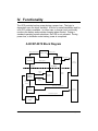
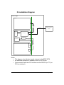
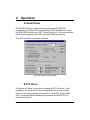
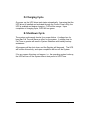
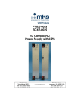
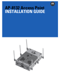
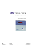
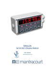
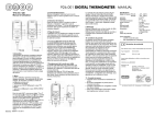
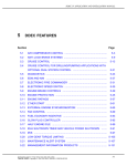
BCKP-0078
3U CompactPCI
UPS
User Manual
13 Altalef St.
Yehud, Israel 56216
Tel: 972 (3) 632-0533
Fax: 972 (3) 632-0458
www.tenta.com
919 Kifer Road
Sunnyvale, CA 94086 USA
Tel: (408) 328-1370
Fax: (408) 328-1371
Document Revision Control
Revision
Comment
BY
Date
E0
Preliminary
TJ
8/25/01
E0.1
Comments
AF
9/4/01
E0.2
Release
TJ
9/4/01
E0.3
Updated COM Handshake Signals
TJ
9/25/01
BCKP-0078 User Manual
Page 2 of 15
Table of Contents
I.
Introduction..................................................................................... 4
II.
Ordering Information...................................................................... 5
III.
Specifications ................................................................................. 6
A.
Physical Specifications ....................................................................... 6
B.
Environmental Specifications............................................................. 6
C.
Front Panel Indicators ......................................................................... 7
D.
Power Specification............................................................................. 7
E.
J2 Signals............................................................................................. 8
IV.
Functionality ................................................................................... 9
A.
BCKP-0078 Block Diagram.................................................................. 9
B.
Battery Backup................................................................................... 10
C.
Power Loss Detection ....................................................................... 10
D.
Installation Diagram .......................................................................... 11
V.
Operation ...................................................................................... 12
A.
Serial Driver........................................................................................ 12
B.
PCI Driver ........................................................................................... 12
C.
COM Handshake Signals................................................................... 13
D.
Charging Cycle................................................................................... 14
E.
Shutdown Cycle................................................................................. 14
VI.
Warranty........................................................................................ 15
BCKP-0078 User Manual
Page 3 of 15
I. Introduction
The BCKP-0078 is a single-slot UPS used with 3U cPCI systems to allow
planned shutdown of a processor during a power loss situation. It can be
located on the cPCI bus or independent within the card cage. A single
slot backplane is available for easy connectivity when used in standalone
mode. The BCKP-0078 is optimized to run with Tenta PWRS-0720.
Communication with BCKP-0078 can be accomplished using standard
COM port handshake signals or PCI bus.
The UPS board form factor, physical dimension and BUS interface comply
with CompactPCI Specification PICMG 2.0 R2.1.
BCKP-0078 User Manual
Page 4 of 15
II. Ordering Information
Part No.
AS00078-01
AS00078-02
AS01050-01
BCKP-0078 User Manual
Description
UPS Card with PCI interface
UPS Card
Backplane, single slot, with mating connector
Page 5 of 15
III. Specifications
A. Physical Specifications
Criteria
PCB Dimensions
Form Factor
Connectors
Front Panel
Weight
Specifications
100mm (3.9370”) Height X 160mm
(6.2992”) Depth X 1.6mm (0.0629”)
Thickness
Plug in Euro card, 3U Height, 8 HP
Width (1 slot), IEEE (1101.1, 101.10
and P1101.11)
Metric 2.0 mm grid, female connector
type A is used for J1 (cPCI BUS – 01
model only) and J2 (Signal distribution)
128.5mm Height X 20.32mm Depth X
2.5 mm Thickness, with power and
status indication LED’s
600 g
B. Environmental Specifications
Criteria
Operating
Temperature
Storage
Humidity
BCKP-0078 User Manual
Specifications
15°C to 45°C – Charge
0°C to 50°C – Discharge
-40°C to 50°C
5%-95% non-condensing
Page 6 of 15
C. Front Panel Indicators
Label
+24 IN
+24 OUT
CHG
ON LINE
Color
Green
Green
Orange
Green
Orange blinking
Orange solid
Orange blinking
Function
+24 VDC supply
+24 VDC to P/S
Battery charging
Battery fully charged
Fast charge pending
Enabled through COM
handshake
Enabled through PCI bus
D. Power Specification
Criteria
Input
Backup
BCKP-0078 User Manual
Specification
24-30 VDC
85 Watts for 2 minutes above 18V
Page 7 of 15
E. J2 Signals
22
Z
GND
21
20
19
18
17
16
15
14
13
12
11
10
9
8
7
GND
GND
GND
GND
GND
GND
GND
GND
GND
GND
GND
GND
GND
GND
GND
6
5
4
3
2
1
GND
GND
GND
GND
GND
GND
A
+24VIN
+24VIN
+24VIN
+24VIN
+24VIN
+24VIN
+24VIN
+24VIN
+24VIN
B
C
COM
COM
COM
COM
COM
COM
COM
COM
COM
COM
D
E
+24VOUT
+24VOUT
+24VOUT
+24VOUT
+24VOUT
NT_CLSD +24VOUT
RS_GND +24VOUT
NT_SHTD +24VOUT
WN_BUF
+24VOUT
F
GND
GND
GND
GND
GND
GND
GND
GND
GND
GND
GND
GND
GND
GND
GND
GND
GND
GND
GND
GND
GND
GND
Legend:
Signal
+24VIN
+24VOUT
COM
NT_SHTDWN_BUF
NT_CLSD
RS_GND
BCKP-0078 User Manual
Notes
Input power
Output power to P/S
24 VDC common
Shutdown COM handshake signal; connects to CTS
(RS-232 Pin 8)
Output for NT to shutdown
Shutdown COM handshake signal; connects to DTR
(RS-232 Pin 4)
Input indicates NT is closed
Logic GND
Page 8 of 15
IV. Functionality
The UPS provides backup power during a power loss. The logic is
dependent upon the driver installed. A driver for serial handshake and for
a full PCI mode is available. In either case, a charge circuit continually
monitors the battery and provides charging when needed. During a
standard operating system shutdown, the UPS is not activated. During
power loss, a shutdown under battery power is completed.
A. BCKP-0078 Block Diagram
Battery power
Battery related signals
Battery pack
Battery power
Charger
circuitry
Switch on/off
circuit
Status signals
J2 PCI
C onnector
Isolation
Cha rge
Con trol
Power
fault
UPS
control
system
configuration
Power
sequence
control
Battery
on/off
Transition
connector
Status
indication
LE Ds
N T & UP S serial interface
Serial
Interface
J1 PCI
C onnector
PC I interface signals
PC I to LO CAL
Bridge
BCKP-0078 User Manual
Page 9 of 15
B. Battery Backup
The battery pack is capable of powering an 85-Watt system for a
minimum of 2 minutes. The battery pack can supply 3.5 amps for more
than 2 minutes.
Charging time of fully discharged battery pack lasts 2.5 hours maximum.
Typical charging time is 1.5 hours.
C. Power Loss Detection
The power failure detection circuit is responsible for identifying a power
failure and switching the Backup. During a short power loss, the logic
may rely on internal capacitance to ensure continuous operation rather
than aborting to a shutdown mode.
A power loss is determined by monitoring +24Vin. If it drops below a
predetermined level, a power failure is identified. The operating system is
then signaled to shutdown.
BCKP-0078 User Manual
Page 10 of 15
D. Installation Diagram
Card Cage
P/S C P C I
24 V D C
OUT
24 V D C IN
External 24 VD C
Supply
BC KP -0078
Battery
Switching C irc uit
R S232
PC I/C ontrol
PC I (O ptional)
C PU
CTS
DTS
COM
PC I
Bus
COM
Backplane
Notes:
• This diagram only indicates signals relevant to the BCKP-0078.
• No additional protection is needed on the 24 VDC IN line.
• Communication with the CPU is either over the RS-232 (no TTL) or
PCI bus (optional).
BCKP-0078 User Manual
Page 11 of 15
V. Operation
A. Serial Driver
The BCKP-0078 can communicate through standard UPS COM
handshaking. Windows NT provides built-in UPS capabilities to control
the BCKP-0078 through the ‘UPS’ Control Panel icon. All communication
between the processor and UPS is through COM handshaking.
The UPS should be configured as follows:
Typical Windows NT UPS Settings
B. PCI Driver
A Windows NT driver is provided to manage all UPS functions. After
installation, the driver will run as a background service, and provides
access to all set up parameters through the ‘TentaUPS’ Control Panel
icon. All communication between the processor and BCKP-0078 is
through the PCI bus.
BCKP-0078 User Manual
Page 12 of 15
Default for UPS Time is 120 s.
Default for Fail Time is 1 s.
Typical PCI Driver Settings
C. COM Handshake Signals
The following table logically describes using the COM handshake signals
to control UPS directly:
Input
NT_CLSD
0 (+8V)
0 (+8V)
1 (-8V)
0 (+8V)
0 (+8V)
1 (-8V)
BCKP-0078 User Manual
Condition
First 120 sec on power up
Battery backup is disabled
After power up
Battery backup is enabled
Disable battery backup
Power failure (>96 ms) occurs
UPS signals NT to shutdown
Power failure (>120 s)
UPS powers off
NT indicates shutdown complete
UPS powers off
Output
NT_SHDWN_BUF
0 (+8V)
0 (+8V)
0 (+8V)
1 (-8V)
1 (-8V)
1 (-8V)
Page 13 of 15
D. Charging Cycle
On power up, the UPS driver task starts automatically. Assuming that the
UPS driver is installed and activated through the Control Panel utility, the
UPS is enabled and begins charging. CHG will be orange. Upon
completion of charging cycle, CHG will turn green.
E. Shutdown Cycle
The system continuously checks for a power failure. A voltage loss for
less than Fail Time will have no effect on the system. A voltage loss for
Fail Time or greater will result in System Shutdown with battery backup
assistance.
All programs will be shut down, and the Registry will be saved. The UPS
will monitor this activity, and upon completion will turn off the System.
If for any reason this does not happen, i.e., the operating system locks up,
the UPS will turn off the System after a time period of UPS Time.
BCKP-0078 User Manual
Page 14 of 15
VI. Warranty
Tenta Technology warrants the original purchaser for two years from the
date of delivery for any defect in the product, material or workmanship.
Product should be used in suitable installation environment and for the
purposes it was designed. Any damages caused by natural disasters such
as: fire, flood, wind and lightning are not covered. For more information,
please contact Tenta Technology customer support (see locations on
front page). Tenta Technology hardware and software are not intended
for use in any manner when human life or safety is at risk and not for use
in life support equipment.
BCKP-0078 User Manual
Page 15 of 15