Download AT-6870 & AT-6875 MAC Layer Bridge EEPROM
Transcript
CentreCOM is a trademark of Allied Telesyn International Corp.
Copyright 1993 Allied Telesyn International Corp.
All rights reserved. No part of this publication may be reproduced without prior
written permission from Allied Telesyn International Corp.
Allied Telesyn International Corp.reserves the right to make changes in
specifications and other information contained in this document without prior
written notice. The information provided herein is subject to change without
notice. In no event shall Allied Telesyn International Corp. be liable for any
incidental, special, indirect, or consequential damages whatsoever, including but
not limited to lost profits, arising out of or related to this manual or the information
contained herein, even if Allied Telesyn International Corp. has been advised of,
known, or should have known, the possibility of such damages.
EPROM Upgrade Kit
for
CentreCOM™ AT-6870 and AT-6875
Bridges
User Manual
Allied Telesyn
950 Kifer Road
Sunnyvale, CA 94086 USA
Tel (800) 424-4284 • Fax (408) 736-0100
Technical Support (800) 428-4835 • Fax (206) 481-3790
PN 613-10406-00 Rev. A
950922
Bridge EPROM Upgrade Kit
Caution
Allied Telesyn AT-6870/6875 bridges come with management software loaded in
two Erasable Programmable Read-Only Memory (EPROM) devices. The
EPROMs provide transparent learning functionality as well as Simple Network
Management Protocol (SNMP) Management Information Base (MIB) II
parameters and supplemental MIB variables for bridges per the Internet Advisory
Board (IAB) Bridge MIB. You can upgrade individual bridges by replacing the
EPROMs in their sockets on the logic board. This EPROM upgrade kit adds the
Internet Protocol (IP) inquiry capability, BOOTP. For information about the
operation of the bridge, refer to the AT-6870/6875 CentreCOM™ MAC-Layer
Bridge Installation and User Manual.
!
EPROM pins are delicate. Use care when handling these components
to prevent pins from being bent or sheared.
5. Using a chip extractor, remove the two EPROMs from their sockets.
Caution
!
The EPROM marked ODD goes on the left and the EPROM marked
EVEN goes on the right. Place EPROMs in the correct sockets and
orient them correctly or damage may result.
Installing the EPROM Upgrade Kit
Caution
!
Installation should be performed with precautions to prevent damage
to static-sensitive components.
1. Make sure the power to the bridge is OFF.
2. Remove the two screws on each side of the bridge that hold the top cover in
place.
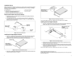
6. Referring to Figure 1, observe the orientation of the two EPROMs. Insert
the EPROM marked “ODD” in the socket on the left, B11 on the Printed
Circuit Board (PCB) silkscreen. Insert the EPROM marked “EVEN” in the
socket on the right, B8 on the PCB silkscreen.The notched end of the
EPROMs’ ceramic cases go toward the back of the logic board. When
inserting the EPROMs in their sockets, carefully line up the pins with the
socket contacts, and exert just enough insertion force to slide the pins into
the contacts evenly and completely.
7. Replace the cover and secure it using the four screws.
3. Remove the top cover. The cover fits tightly, and it may be necessary to use
a screwdriver to initially dislodge it.
Verification of Operation
4. Orient the unit with the front towards you. The power supply should be on
the left, and the port LEDs should be on the right. See Figure 1.
Before putting the bridge back in service, you can make sure it is functional by
running its power-up diagnostic routines.
Plug the bridge in if the power cord is unplugged and turn the power ON.
ODD
B11
EVEN
B8
B6
B7
B8
The green System Power indicator and the red Diagnostics indicator come ON, and
the bridge tests the two network channels. First the Transmit and Receive
indicators for Channel B flash alternately for a few seconds, then this is repeated
for Channel A. If the unit does not pass, the Diagnostics indicator illuminates and
stays ON steadily.
The Diagnostics indicator goes OFF when the bridge passes the diagnostic tests,
signaling that it is ready for use.
Channel A LEDs
Front Panel of Bridge
Transmit Receive
Figure 1: Location and Orientation of the EPROMs on the AT-6870/6875 Logic Board
Network Management
The SNMP agent enables the user to manage the system from any industrystandard SNMP Network Management Console (NMC) running an SNMP
management application that can handle MIB II.
A network management application which handles only MIB II would not be able
to perform all the management functions of the AT-6870/6875.
Bridge EPROM Upgrade Kit
Caution
Allied Telesyn AT-6870/6875 bridges come with management software loaded in
two Erasable Programmable Read-Only Memory (EPROM) devices. The
EPROMs provide transparent learning functionality as well as Simple Network
Management Protocol (SNMP) Management Information Base (MIB) II
parameters and supplemental MIB variables for bridges per the Internet Advisory
Board (IAB) Bridge MIB. You can upgrade individual bridges by replacing the
EPROMs in their sockets on the logic board. This EPROM upgrade kit adds the
Internet Protocol (IP) inquiry capability, BOOTP. For information about the
operation of the bridge, refer to the AT-6870/6875 CentreCOM™ MAC-Layer
Bridge Installation and User Manual.
!
EPROM pins are delicate. Use care when handling these components
to prevent pins from being bent or sheared.
5. Using a chip extractor, remove the two EPROMs from their sockets.
Caution
!
The EPROM marked ODD goes on the left and the EPROM marked
EVEN goes on the right. Place EPROMs in the correct sockets and
orient them correctly or damage may result.
Installing the EPROM Upgrade Kit
Caution
!
Installation should be performed with precautions to prevent damage
to static-sensitive components.
1. Make sure the power to the bridge is OFF.
2. Remove the two screws on each side of the bridge that hold the top cover in
place.
6. Referring to Figure 1, observe the orientation of the two EPROMs. Insert
the EPROM marked “ODD” in the socket on the left, B11 on the Printed
Circuit Board (PCB) silkscreen. Insert the EPROM marked “EVEN” in the
socket on the right, B8 on the PCB silkscreen.The notched end of the
EPROMs’ ceramic cases go toward the back of the logic board. When
inserting the EPROMs in their sockets, carefully line up the pins with the
socket contacts, and exert just enough insertion force to slide the pins into
the contacts evenly and completely.
7. Replace the cover and secure it using the four screws.
3. Remove the top cover. The cover fits tightly, and it may be necessary to use
a screwdriver to initially dislodge it.
Verification of Operation
4. Orient the unit with the front towards you. The power supply should be on
the left, and the port LEDs should be on the right. See Figure 1.
Before putting the bridge back in service, you can make sure it is functional by
running its power-up diagnostic routines.
Plug the bridge in if the power cord is unplugged and turn the power ON.
ODD
B11
EVEN
B8
B6
B7
B8
The green System Power indicator and the red Diagnostics indicator come ON, and
the bridge tests the two network channels. First the Transmit and Receive
indicators for Channel B flash alternately for a few seconds, then this is repeated
for Channel A. If the unit does not pass, the Diagnostics indicator illuminates and
stays ON steadily.
The Diagnostics indicator goes OFF when the bridge passes the diagnostic tests,
signaling that it is ready for use.
Channel A LEDs
Front Panel of Bridge
Transmit Receive
Figure 1: Location and Orientation of the EPROMs on the AT-6870/6875 Logic Board
Network Management
The SNMP agent enables the user to manage the system from any industrystandard SNMP Network Management Console (NMC) running an SNMP
management application that can handle MIB II.
A network management application which handles only MIB II would not be able
to perform all the management functions of the AT-6870/6875.
CentreCOM is a trademark of Allied Telesyn International Corp.
Copyright 1993 Allied Telesyn International Corp.
All rights reserved. No part of this publication may be reproduced without prior
written permission from Allied Telesyn International Corp.
Allied Telesyn International Corp.reserves the right to make changes in
specifications and other information contained in this document without prior
written notice. The information provided herein is subject to change without
notice. In no event shall Allied Telesyn International Corp. be liable for any
incidental, special, indirect, or consequential damages whatsoever, including but
not limited to lost profits, arising out of or related to this manual or the information
contained herein, even if Allied Telesyn International Corp. has been advised of,
known, or should have known, the possibility of such damages.
EPROM Upgrade Kit
for
CentreCOM™ AT-6870 and AT-6875
Bridges
User Manual
Allied Telesyn
950 Kifer Road
Sunnyvale, CA 94086 USA
Tel (800) 424-4284 • Fax (408) 736-0100
Technical Support (800) 428-4835 • Fax (206) 481-3790
PN 613-10406-00 Rev. A
950922


