Download Installation and operation
Transcript
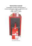
MANUAL
FOR OPERATION OF COMBINED WOOD GASIFICATION
HOT WATER BOILER, UTILIZING WOOD LOGS, WOOD
PELLETS AND DRY CALIBRATED WOOD CHIPS, FROM
SERIES
3Fera 25/35/45
http:// www.greenecotherm.eu
Manufacturer
ZMM Haskovo PLC.
Address
67 Saedinenie, 6300 Haskovo, Bulgaria
Telephone
+359 800 15 145
Fax
+359 38 603070
e-mail
greenecotherm@erato.bg
home page
www.greenecotherm.eu
The manufacturing company thanks you for the contribution of your choice.
The manufacturing company provides this manual in help to the team that will install, adjust
and service this system, as well as to the customer that will operate it.
The manufacturing company requires that the technicians performing the above presented
procedures has passed training course for the activities performed with the product.
User manual for operation and installation of combined wood gasification hot water boiler, operating
with wood logs, wood pellets and dry calibrated wood chips, from series “3Fera 25/35/45”
(Edition: 21.12.2012 г. 05:44:00 ч.)
3Fera 25/35/45
2
CONTENT
page
1.
2.
3.
4.
5.
6.
6.1.
6.2.
6.3.
6.3.1.
6.3.2.
6.3.3.
6.3.4.
6.4.
6.5.
6.5.1.
6.5.2.
6.6.
6.6.1.
6.6.2.
6.7.
6.7.1.
6.8.
6.9.
6.10.
6.11.
6.12.
7.
8.
9.
INFORMATION RELATED TO THE USERS SAFETY. ............................................................ 4
DESRIPTION AND ADVANTAGES OF COMBINED WOOD GASIFICATION HOT WATER
BOILER FROM SERIES “3 FERA”. ........................................................................................... 5
TECHNICAL DATA FOR COMBINED WOOD GASIFICATION HOT WATER BOILER FROM
SERIES “3 FERA”. ..................................................................................................................... 7
CONSTRUCTION DESCRIPTION OF COMBINED WOOD GASIFICATION HOT WATER
BOILER FROM SERIES “3 FERA”. ......................................................................................... 10
MOUNTING AND INSTALLATION OF THE BOILER.............................................................. 17
INITIALIZATION OF THE APPLIANCE IN OPERATION. ....................................................... 23
GENERAL REQUIREMENTS ABOUT THE USED FUEL....................................................... 23
GENERAL REQUIEMENTS DURING OPERATION OF THE HEATING INSTALLATION ….23
INITILIZATION OF HOT WATER BOILER FROM SERIES “3FERA” IN OPERATION. ......... 24
ADJUSTMENT OF THE FIRING AIR FLOW RATE THERMO-REGULATION VALVE. ......... 25
INTERFACE CONTROL PANEL OF HOT WATER BOILER FROM SERIES “3FERA”. ........ 26
BOILER POWER SUPPLY. ..................................................................................................... 27
BOILER SWTICH ON. ............................................................................................................. 28
CHANGING THE BOILER OPERATION PARAMETERS. ...................................................... 30
PARAMETERS FOR ADJUSTMENT OF THE BOILER OPERATION. .................................. 32
OPERATION OF THE BOILER WITH FUEL - MANUAL REFUELING WITH FIREWOOD.... 32
OPERATION OF THE BOILER IN COMBINED MODE - AUTOMATED FEEDING WITH
WOOD PELLETS OR DRY CALIBRATED WOOD CHIPS. .................................................... 34
ADJUSTMENT OF THE BOILER HEATING OUTPUT. .......................................................... 36
OPERATION MODE DURING FIREWOOD UTILIZATION..................................................... 36
BOILER OPERATION IN COMBINED MODE......................................................................... 37
STOPPING THE BOILER OPERATION.................................................................................. 38
BOILER EMERGENCY SHUT DOWN. ................................................................................... 39
BOILER SHUT DOWN............................................................................................................. 39
BOILER CLEANING................................................................................................................. 39
USER INTRODUCTION WITH THE SERVICING AND ADJUSTMENT PROCEDURES OF
THE BOILER............................................................................................................................ 41
SAFETY AND UNPREDICTED RISKS.................................................................................... 41
ACTIVITIES AFTER THE APPLIANCE LIFE CYCLE EXPIRY. .............................................. 42
FAILURES AND TROUBLESHOOTING.................................................................................. 43
WIRING DIAGRAM OF THE APPLIANCE. ............................................................................. 45
WARRANTY CONDITIONS. .................................................................................................... 47
3Fera 25/35/45
3
1.
INFORMATION RELATED TO THE USERS SAFETY.
The manual book for operation of combined wood gasification hot water boiler from series
„3Fera” is designated for users and authorized servicing specialists.
The user must know that:
All activities related to the heating installation must be performed only by authorized
installers, which have acquired legal rights for such activities from the local
authorities;
All activities related to the electrical installation must be performed only by
electricians;
The initialization of the appliance in operation, including visual check of the heating
installation, adjustment and boiler start up, must be performed by certified technician,
authorized by the manufacturing company representatives;
Please observe the following rules during installation, initial start up, adjustment and
operation initialization of combined wood gasification hot water boiler from series „3Fera”:
All legal provisions related to the safety techniques;
Environment protection provisions;
Installation, initial start up and adjustment provisions;
The harmonized EU provisions, applicable in the relevant country;
Please strictly observe the presented safety instructions, in order to avoid risks and harms to
people, properties, as well as to environment polluting.
Please pay attention to the following symbols from the current manual book:
Danger
This symbol warns the users about possible human health risks.
Warning
This symbol warns the users about possible risks and harms to
properties and environment.
Information
This symbol provides additional information to the users.
Notation „3Fera” is used in the present manual book, which includes the
combined wood gasification hot water boiler models
„3Fera 25”, ”3Fera 35” and „3Fera 45”.
For your safety it is important to become well familiar and read carefully
the present instruction, before performing any activities over the
installation and operation of this appliance. Non-observance of the
instructions below might lead to damages and fatal consequences, for
which the manufacturing company will not take responsibility.
3Fera 25/35/45
4
2.
DESRIPTION AND ADVANTAGES OF COMBINED WOOD GASIFICATION HOT
WATER BOILER FROM SERIES “3 Fera”.
The steel made combined wood gasification hot water boilers from series „3Fera” are
designated for heating and/or providing hot domestic water of single family houses, offices,
business buildings and others.
The boiler represents welded steel construction, optimized for high efficiency and economic
operation, and also for easy servicing and cleaning. The reliable steel made construction of
the boiler is specially designed for firing of dry wood (with moistureup to 20%) and for other
type reserve fuel (wood pellets or dry calibrated wood chips) by fuel gasification with
maximum efficiency, economic operation and easy servicing. Its manual initial firing and the
automatic switching to reserve type of fuel provide comfort, approaching the electrical
heating, diesel fuel or natural gas heating.
The generated heat energy is acquired by the boiler body heat exchanging surfaces and is
transferred to the heat carrier (in most cases circulations water) in the heating installation or
to the hot domestic water system.
The appliance can utilize the following types of fuels:
Firewood with the following parameters:
o Clean firewood. Usage of materials with improper impurities as paint, lacquer
coatings, organic or non-organic substances is not applicable;
o The firewood logs length must correspond to the boiler fuel chamber depth;
o The cross cut (diameter) of the firewood must be: D ≤ 200mm;
o The fuel moisturemust be: W r ≤ 20%;
Wood pellets with diameter Ø 6-8 mm, category ENplus-A1, ENplus-A2 and ENplusB according to standard EN 14961-2:2010 or category: A, AB, B, BC, C, CD, E, EF
according to the methodic developed and used by the appliance manufacturing
company;
Dry calibrated wood chippings with main fraction size Р=20mm, moisture W r≤10.0%
and ash content Ad≤2.0%. This fuel must correspond to the requirements of standard
OENORM M7133:G30, W10, ash class A1 or A2. According to the European
standard for solid bio-fuels EN 14961-1:2010, Annex 2, P16, M10, A0.7 or A1.5,
BD200.
The standard equipment of combined hot water wood gasification boiler from series “3Fera”
includes:
Hot water wood gasification boiler from series “3Fera” - 1 unit;
Directing fireclay made component for the combustion chamber - 1 pc;
Thermo-regulation valve for the firing air flow rate – 1 pc;
Steel made cleaning brush – 1 pc;
Steel made cleaning scraper – 1 pc;
User manual book for installation and operation of wood gasification hot water boiler,
utilizing firewood, wood pellets and dry calibrated wood chips: “3Fera 25”, “3Fera 35”
and “3Fera 45” – 1 pc.
The appliance consists of:
Steel made heat exchanging unit for heating of the heat carrier;
Flue gas extraction fan, for extracting the flue gasses out of the boiler;
Refueling chamber;
Fireclay combustion chamber;
Convective heat exchanging module (tube bundle), in which the firing air is
preheated;
Control board for monitoring and controlling of the appliance;
3Fera 25/35/45
5
Mineral wool heat isolation;
The appliance is equipped with:
Thermo-manometer (temperature-pressure gauge) for monitoring the operation
parameters of the circulations water;
Thermostat for controlling the flue gas extraction fan operation;
Thermostat for indication of the boiler operation mode and the necessity for cleaning
– it is offered optionally;
Emergency thermostat for protecting the appliance from overheating;
Boiler tube(serpentine) for emergency cooling of the boiler in case of exceeding its
operation temperature;
Combined fuel feeding auger for dry calibrated wood chips (P20, EN 14961-2;
moisture up to 10%) and for wood pellets with diameter Ø 6-8 mm. It suits all boiler
models and is offered as an optional equipment;
Advantages of the boiler:
Availability for usage of reserve fuel, after completion of the firewood burning – wood
pellets or dry calibrated wood chips, which provides INDEPENDENT operation mode;
High efficiency (Eff.coef. = 93%) during utilization of the three fuel types, which
guarantees exclusively economic operation and low costs for heating;
Easy servicing (handling) thanks to its wide door and availability for firing of wood
logs with diameter up to 20 cm, maximum length 50 cm and moisture up to 20%;
Combustion chamber equipped with high quality ceramics, which guarantees
maximum efficient burning process;
Cleaning mechanism for the heat exchanger tube bundle, ensuring stable efficiency;
Thanks to the firing air flow rate thermo-regulation valve maximum fuel utilization and
economic operation of the boiler are guaranteed;
Reliable and safe operation, thanks to its stainless unloading serpentine and
compliance with the requirements of EN303-5 standard;
Availability for adjustment of the heating output within wide range;
The boiler is factory equipped with flue gas extraction fan;
Possibility for monitoring of the processes in the combustion chamber through the
doors monitoring glasses;
Components by reputable European manufacturers;
If a thermostat-mixing group Laddomat is added, the life length of the appliance will
be longer and the fuel economy will be higher (up to 20%);
The boiler is ecological with low harmful emissions levels – below the strictest
requirements of the European standards.
LADDOMAT is thermostat mixing group, which assists for quicker reaching to
operation temperatures during heating of water from accumulation tank and
implements the process of temperature stratification.
3Fera 25/35/45
6
3.
TECHNICAL DATA FOR COMBINED WOOD GASIFICATION HOT WATER
BOILER FROM SERIES “3 Fera”.
The heating-technical data of combined wood gasification hot water boiler from series
“3Fera”, utilizing firewood, wood pellets and dry calibrated wood chips, are presented in
Table 3.1.
Table 3.1. Heating-technical data of combined wood gasification hot water boiler from series
“3Fera”
Parameter
Boiler model
Nominal output
Heating output operation
range
Used fuel
Wood pellets categories,
according to standard EN
14961-2
Wood pellets categories
according to the appliance
manufacturing company
method
Dry calibrated wood chips
category, according to
standard EN 14961-1
Firewood consumption at
nominal heating output
Wood pellets consumption
at nominal heating output
Dry calibrated wood chips
consumption at nominal
heating output
Efficiency at nominal
heating output
Wastes from the fuel
burning
Dimension
3Fera 25
Value
3Fera 35
3Fera 45
kW
25
35
45
kW
9–25
11 – 35
15 –45
-
-
Firewood, wood pellets, dry calibrated wood
chips
ENplus-A1, ENplus-A2, ENplus-B
-
A, AB, B, BC, C, CD, E, EF
-
Annex 2, P16, M10, A0.7
kg/h
7.9
11.1
14.2
kg/h
5.6
7.8
10.1
kg/h
6.1
8.6
11.0
℅
93.0
93.0
93.0
ash
The quantity depends on the fuel ash content
The dimensions and technical parameters of combined hot water boiler from series “3Fera”
are presented in Table 3.2.
3Fera 25/35/45
7
Table 3.2. Dimensions and technical parameters of combined hot water boiler from series
“3Fera”.
Parameter
Boiler model
Weight
Fuel chamber volume
Water volume
Overall size of the boiler WxHxL
Max. operating pressure
Recommended operation water
temperature
Minimum temperature of the inlet
water
Chimney draught
Supply voltage
Expansion tank type in the
installation
Environment protection index
Connection Inlet/outlet water
links
pipes
Drain pipe
Emergency
serpentine (tube)
Flue outlet diameter
Dimension
kg
l
l
mm
bar
ºC
Value
3Fera 35
438
160
150
800х1100х1250
2.0
3Fera 25
418
120
126
800х1100х1150
80-85
ºC
60
Pa
-
18 - 24
50Hz; 230V
-
Opened or closed
-
3Fera 45
485
160
200
800х1200х1250
IP20
IP20
IP20
G
1 1/2”
G
1/2”
G
¾” (inlet and outlet)
mm
150
The firewood parameters as main recommended fuel type for combined wood gasification
hot water boiler from series „3Fera” are presented in Table 3.3.
Table 3.3. Recommended fuel parameters – dry firewood.
Parameter
Fuel type
Moisture
Minimum fuel caloricity (minimum calorific value)
Dimension
Value
Firewood
%
MJ/kg
kWh/kg
≤ 20%
>13.9
>3.9
Table 3.4 represents the parameters for wood pellets as type of fuel for hot water boilers
from series „3Fera”.
3Fera 25/35/45
8
Table 3.4. Wood pellets parameters.
Parameter
Diameter of the granules
Recommended fuel caloricity (net calorific value)
Dimension
mm
MJ/kg
kWh/kg
Wood pellets category according to standard EN
14961-2
Wood pellets category according to the appliance
manufacturing company categorization
Moisture
%
Value
6–8
>17.2
>4.7
ENplus-A1, ENplusA2, ENplus-B
A, AB, B, BC, C, CD,
E, EF
Max. 8 – 10%
The parameters for dry calibrated wood chips as type of fuel for hot water boilers from series
„3Fera” are presented in Table 3.5.
Table 3.5 Dry calibrated wood chips parameters.
Parameter
Typical size of dry calibrated wood chips
Moisture
Ash content
Bulk density
Recommended fuel caloricity (net
calorific value)
Dry calibrated wood chips parameters,
according to standard EN 14962-1
Notation
Р
М (W r)
А
BD
Qnet
-
Dimension
mm
%
%
kg/m3
MJ/kg
kWh/kg
Value
20
≤ 10
≤ 1.5
200
>16.0
>4.4
P16A, M10, A0.7/A1.5, BD200
The combined wood gasification hot water boilers from series „3Fera” are not
designated for utilization of every solid fuel type, including coal and cokes.
3Fera 25/35/45
9
4.
CONSTRUCTION DESCRIPTION OF COMBINED WOOD GASIFICATION HOT
WATER BOILER FROM SERIES “3 Fera”.
The combined wood gasification hot water boiler from series „3Fera” consists of the following
main components and modules:
Heat exchanger which presents welded steel plate construction. In the upper part of
the boiler is formed the fuel loading chamber, in which the substances volatile from
the wood. In the lower part of the heat exchanger is formed a combustion chamber, in
which the combustion nozzle and the fireclay lining of the combustion chamber are
formed;
The fireclay made combustion nozzle, positioned in the refueling chamber lower part,
provides conditions for effective substances volatile (the burning gasses, separated
during the fuel gasification) and their burning;
Fireclay made directing elements, mounted in the combustion chamber, providing
optimum combustion and assist for complete fuel burning;
Flue gasses extraction fan, installed in the back side of the boiler;
Air-distribution box, which is used for adjusting the primary air flow rate by a flap. This
box also serves for preheating of the firing air, before it is led to the burning zone. The
inlet section of the box is equipped with a flap which is controlled by thermoregulation valve (TRV). The TRV is linked to it by a chain and its function is to
partially close the air inlet section when the circulations water temperature increases;
The water inlet muff is threaded inside (see Table 3.2 for its size) and is positioned on
the boiler’s low left back side. The water outlet muff is threaded inside (see Table 3.2
for its size) and is positioned on the left top back side of the boiler. By these muffs the
boiler connects to the heating system;
The draining muff is with inside threading (see Table 3.2 for its size). It must be
equipped with draining cock;
Emergency unloading boiler tube (serpentine) which serves for cooling of the
circulations water in the boiler body, when the temperature exceeds the highest limits.
This boiler tube is with outside thread G3/4”;
Flue outlet (with external diameter Φ150 mm) positioned in the top back side of the
boiler, after the convection pipeline of the boiler and is used for cooling of the flue
gasses and preheating of the firing air;
Steel made heat exchanger and its cover, which are isolated with mineral wool, that
serves for limiting of the heat losses transfer to the surrounding environment;
Fuel chamber and combustion chamber cast iron doors, which provide excellent
isolation and sealing of the boiler volume;
Outside decoration covers that are made from steel and are coated with quality color
paint;
Combined fuel transport auger (it is offered as additional option) for feeding of the
combined hot water boilers from series “3Fera” with wood pellets or dry calibrated
chips.
General view of combined wood gasification hot water boiler from series “3Fera”, utilizing
firewood, wood pellets and dry calibrated chips, is presented in Figure 4.1.
3Fera 25/35/45
10
Figure 4.1. General view of combined wood gasification hot water boiler from series “3Fera”.
The fuel feeding auger for wood pellets and dry calibrated wood chips is
offered as an option for all models of the combined hot water boiler from
series “3Fera”.
Figure 4.2 represents front view of the combined hot water boiler from series “3Fera”.
Rear side view of the boiler from series “3Fera” is presented in Figure 4.3.
3Fera 25/35/45
11
Figure 4.2. Front view of combined wood gasification hot water boiler from series “3Fera”.
Boiler control panel
Linkage of bars for
semi-automatic
cleaning of the heat
exchanger’s tube
bundle from the ash
residues
Fuel chamber
Combustion chamber
Monitoring glass on
the combustion
chamber door
Figure 4.3. Combined wood gasification hot water boiler from series “3Fera” – rear view.
1. Primary air valve 1
2. Primary air valve 2
3. Total air valve
4. Secondary air valve
5. Ash cleaning cover
6. Reserve fuel inlet
7. Emergency cooling boiler tube (input/output)
3Fera 25/35/45
12
Cross section view of combined wood gasification hot water boiler from series “3Fera”, with
shown flue gas and ash directions, is presented in Figure 4.4.
The overall sizes of combined wood gasification hot water boiler from series “3Fera” are
presented on Figure 4.5.
Figure 4.4. Cross section view of combined wood gasification hot water boiler from series
“3Fera” with shown flue gas and ash directions.
Flue gas extraction fan
Outlet to chimney
Ash cleaning
mechanism
Fuel chamber
Specialized nozzle for
wood firing, wood
pellets and dry
calibrated wood chips
Directing fireclay
component
Combustion chamber
Inlet to the boiler’s tube
bundle
3Fera 25/35/45
13
Figure 4.5. Overall sizes of combined wood gasification hot water boiler from series “3Fera”.
Exploded view of the combined fuel transport auger (offered as an option), used for feeding
combined wood gasification hot water boilers from series “3Fera” operating with reserve fuel
(wood pellets or dry calibrated wood chips), is presented on Figure 4.6.
3Fera 25/35/45
14
Figure 4.6 Exploded view of combined fuel transport auger.
1.
2.
3.
4.
5.
6.
Cover
Chain gear – auger
Chain gear – flap
Chain tensioner
Sectioned dozing flap
Body
7. Pipe
8. Auger/Screw
9. Shut down device
10. Moving cover
11. Motor-gear
Figure 4.7 presents the dimensions of combined fuel transport auger for feeding of combined hot
water boilers from series “3Fera”, with wood pellets or dry calibrated wood chips.
3Fera 25/35/45
15
Figure 4.7 Dimensions of combined fuel transport auger.
3Fera 25/35/45
16
5.
MOUNTING AND INSTALLATION OF THE BOILER.
The following requirements must be observed during the mounting and installation of combined
wood gasification hot water boiler from series “3Fera”:
The room designated for the boiler installation must provide constant air intake, which is
needed for the burning process and for good ventilation;
Installation of the boiler in living premises, including corridors, is not allowed;
The boiler connection to the heating installation must be performed only by qualified
technician;
The installation and maintenance of solid fuel hot water boilers must be performed by
specialized companies, which have acquired legal rights for performing such activities;
The combined hot water boiler from series “3Fera” can be connected to the heating system
with opened or closed expansion tank, which has to be calculated during the installation
project development;
The combined hot water boiler from series “3Fera” is connected to the heating system with
OPENED or CLOSED expansion tank type. In case the system is with closed type
expansion type a safety pressure valve must be installed, which opens if the boiler
operation pressure exceeds (0.25MPa). This valve must be certified according to PED
97/23;
Before initialization of the boiler in operation, the entire heating installation must be filled
with water and air freed (eliminate the air).
The boiler servicing (handling) must be performed only by adult persons, which are well
familiar with the appliance operation manual.
During the boiler transportation precaution measures must be taken, against
damage or braking of the fireclay component, which is positioned in the boiler’s
combustion chamber.
The boiler installation requires preliminary developed project, complying with the acting norms and
prescriptions:
For the heating system - BDS EN 303-5/2000 - „Central heating hot water boilers – part 5:
hot water solid fuel boilers with maximum nominal heating output up to 300 kW –
terminology, requirements, tests and notation”;
For the chimney;
Fire safety prescriptions;
For the electrical supply system - BDS EN 60 335-1/1997 - “Safety of domestic electrical
appliances”;
The opened area, for supplying the boiler room with fresh air, must be at least 0.04 m2;
The positioning of the boiler for easy manipulation (without combined fuel transport auger,
which is offered as an option) must comply with:
o The boiler must be positioned over inflammable pad with minimum height of 50
mm;
o The minimum distance for manipulation in front of the boiler must be 1000 mm;
o The minimum allowed distance between the boiler rear side and a wall must not be
less than 400 mm;
o The minimum distance between the boiler left and right side to a wall must be 500
mm, in order to ensure free access to its side cover panels and its rear side;
o The minimum distance of the free area over the boiler must be at least 600 mm, in
order to ensure easy access to its control components and cleaning of the
convection pipeline.
Positioning of the boiler and the combined fuel transport auger for feeding of reserve fuel:
o The minimum allowed distance between the rear side of the hopper (storage
container), in which the fuel transport auger is mounted and a wall must be at least
400 mm;
3Fera 25/35/45
17
o
o
The minimum distance from the left and right sides of the reserve fuel transport
auger to a wall must be at least 500 mm, in order to ensure free access to its
manhole cover and to the boiler rear side as well;
The minimum free area above the fuel transport auger must be at least 600 mm, in
order to ensure easy access for servicing of its control components and to its gear
cover.
After the boiler has been positioned at its designated place, the following activities for its
equipment and preparation must be completed:
Mounting and positioning of the fireclay component in the boiler’s combustion chamber
(Figure 5.1 and Figure 5.2);
Figure 5.1. Directional fireclay made component, which must be positioned in the boiler’s
combustion chamber.
Figure 5.2. Picture of correctly positioned directing fireclay made component, mounted in the
boiler’s combustion chamber.
The positioning of the directing fireclay component must be performed carefully, in
order to protect it from damaging or braking. It is placed under the boiler firing
nozzle and must be backed to the rear wall of the boiler’s combustion chamber.
3Fera 25/35/45
18
Installation of the firing air flow rate thermo-regulation valve (Figure 5.3);
Figure 5.3. Thermo-regulating valve for the firing air flow rate adjustment.
Thermo-regulating
valve
Firing air flow rate
regulation flap
The thermo-regulation valve for the firing air flow rate is mounted and is linked with a chain which
moves the flap for regulation of the boiler air intake.
The chain length adjustment and the closing level of the boiler firing air inlet
channel must be performed when the boiler is operating and has reached operating
parameters. When the boiler starts the flap must be opened in order to provide
access for the firing air.
Installation of the safety temperature valve that supplies water for emergency cooling of
the boiler, in case the circulations water temperature has been exceeded above the limits;
The temperature safety valve’s sensor has to be screwed in a muff, positioned at the upper part of
the boiler heat exchanger. The temperature safety valve’s operation module must be screwed in
one of the two ends (depending on the installation availability) of the emergency cooling boiler
tube (serpentine) – Figure 5.4. The inlet side of the temperature safety valve must be linked to
the water supply pipeline (that supplies fresh clean water) or to another source of clean water
under pressure. The outlet side of the emergency cooling boiler tube (serpentine) must be linked
to a drain pipe, so the outlet water can easily and safely flow to the sewers.
3Fera 25/35/45
19
Figure 5.4. View of the boiler with shown ends of the emergency cooling boiler tube (serpentine).
The inlet and outlet pipelines of the heating installation must be connected to the relevant
boiler muffs (Figure 5.5);
Figure 5.5. View of the boiler with shown muffs for connecting to the heating installation and its
outlet to the chimney.
Hot circulations water outlet –
to the heating installation
Outlet for extraction of the flue
gasses to a chimney
Flap for regulation of the firing
air flow rate
Cooled water inlet – from the
heating installation
Positioning of the boiler in compliance with the requirements for connecting to the electrical
supply network – the appliance must be positioned so free access to the socket box is
guaranteed (230V/50Hz);
3Fera 25/35/45
20
The completion of the installation works and the hot test of the boiler must be noted
in its warranty card. It is mandatory to fill all fields with the required information.
The heating installation and the boiler have to be filled with circulations liquid – in most
cases with fresh water. The water, used for filling the boiler and the heating installation
must be transparent, without color, without deposits, oils and aggressive chemical
impurities. The hardness of the water must comply with the tolerable norms, presented in
the next table. In case the used water parameters do not correspond to those presented in
the table, then water with suitable characteristics should be used or chemical treatment
must be performed.
Table 5.1 represents the heating system water parameters, which must comply with the
requirements of standard BDS 15207-81.
Table 5.1. Parameters of suitable water for the heating installation.
Parameter
Overall hardness
Oxygen content
Oil and heavy oil products
Overall hardness
Salts content
Total alkalinity
рН
Content of free СО2
Dimension
mg.eq/kg
mg/kg
mg/kg
mg/kg
mg/kg
mg/kg
mg/kg
Value
30
100
3
50
6000
30
8.0 – 9.5
Not allowed
In case the boiler is connected to heating installations, where the water is in contact with copper
(for example copper pipes), the pH (hydrogen exponent) value must not exceed 10.
The manufacturing company recommends the following hydraulic diagram for connecting a
combined wood gasification hot water boiler from series “3 Fera” to a heating installation together
with heat accumulator and water mixing valve, as presented on Figure 5.6.
3Fera 25/35/45
21
Figure 5.6. Recommended hydraulic diagram for connecting hot water boiler from series “3 Fera”
to heating installation, heat accumulation tank and water mixing valve.
Cold tap
water
To heating
system
Domestic hot
water
From heating
system
Tap water
Drainage
Table 5.2. Identification of the components marked on Figure 5.6.
No.
1
2
3
4
5
6
7
8
9
10
Identification
Hot water boiler from series
“3Fera”
Safety valve
Boiler hot domestic water
Retaining valve
Circulations pump 1
Safety valve
Opened or closed expansion
tank
Ball valve
Three way mixing valve
Circulations pump 2
No.
11
12
13
14
15
16
17
18
22
23
24
Identification
Ball valve
Water filter
Temperature valve TV
Retaining valve
Contact thermostat
Heat accumulator
Automatic water refilling device
Filling and draining cock
Air free device with flap
Safety valve
Retaining flap
According to standard BDS EN 303-5 the heat accumulator is mandatory part from
the heating installation, in which the solid fuel hot water boiler is installed. The
capacity calculation of such heat accumulator can be performed by the method
described in this standard (BDS EN 303-5). The developed by the manufacturing
company procedure can also be used.
3Fera 25/35/45
22
6.
INITIALIZATION OF THE APPLIANCE IN OPERATION.
The combined wood gasification hot water boilers from series “3Fera” must be
initiated in operation only by specialized company, authorized to perform such
activities.
6.1.
GENERAL REQUIREMENTS ABOUT THE USED FUEL.
In order to achieve complete burning it is necessary to use only dry fuel, with
characteristics that comply with the fuel requirements. The manufacturing company
recommends storing of the fuel in dry and ventilated premises or under roof, where it will
be protected from moistening;
Storing the fuel next to the boiler or at distance less than 500 mm is forbidden;
The recommended distance by the manufacturing company is minimum 1000 mm. It is
better to store the fuel in a neighbor premise;
The fire safety requirements must be observed during the boiler installation and the fuel
storing. It is recommended to keep fire extinguisher at near and safe place.
6.2.
GENERAL REQUIEMENTS DURING OPERATION OF THE HEATING INSTALLATION.
In case the heating installation is designed with opened expansion tank, then the following should
be taken into account: the heating installations with opened expansion tank provide direct contact
between the heating (circulations) water and the surrounding atmosphere. During the heating
season the water in the expansion tank absorbs oxygen (through their contact surface), which
increases the corrosive action of the circulations liquid over the steel surfaces, and circulations
liquid (water) vaporization could be noticed also. For the system refilling must be used only water
that complies with the usage requirements of circulations liquids, according to standard BDS
15207-81. During the heating season it is necessary to keep constant water quantity in the
heating system. Refilling with water should be performed carefully in order to prevent access of air
to the system. The circulations water must be used only for its designation. It is not allowed to
drain the water out of the boiler or the system, except in case of repairs.
In case the heating installation is designed with closed expansion tank, then the following should
be taken into account: the heating systems with closed expansion tank are systems operating
under pressure and do not allow direct contact between the circulations water and the surrounding
atmosphere. Therefore such systems are not endangered by intake of air from the atmosphere.
Such systems are under pressure and it must be controlled, so they can function without failures –
not only the exceeded pressure is dangerous, because the mechanical components loads
increase (and the possibility for defects increases), but also the pressure decrease could lead to
the system improper functioning – even to absorb air from the environment. Therefore it is
necessary to keep constant pressure of the water in the heating system. The circulations water
must be used only for its designation. It is not allowed to drain the water out of the boiler or the
system, except in case of repairs.
It is recommended to check the water pressure in the heating system on every 14 days.
In case of necessity the system can be refilled (toped up) with water, but only when the boiler is in
cold condition. This is necessary in order to prevent the steel made heat exchanger of the boiler
from damages, caused by thermal stresses by the intake of cold water.
In case the boiler and the heating installation will not be operated for long period of time and there
is possibility of local circulations water freezing, then it is recommended to drain the water out of
the system. It is also good to know that the presence of water in the heating installation and the
boiler protects the steel surfaces from contact with the air oxygen and respectively from corrosion.
3Fera 25/35/45
23
6.3.
INITILIZATION OF HOT WATER BOILER FROM SERIES “3Fera” IN OPERATION.
The following requirements must be observed during initialization of combined wood gasification
hot water boiler from series “3Fera”:
The boiler servicing/handling must be performed in compliance with the maintenance and
operation manual;
The boiler must be serviced /handled only by adult people, which are well familiar with the
operation manual of the appliance.
Presence of children near the boiler is not allowed.
Any intervention over the boiler operation, which may lead to danger for the servicing
personal health or other indirectly related persons is not allowed;
In case easy flammable gasses may penetrate/come in the boiler room, also during repairs
which can be accompanied by separation of gas (for example coating with flammable
paints and materials, flooring), the boiler must be shut down from operation;
During the boiler operation it must be periodically checked by the servicing/handling
personal (the user);
The user must not perform repairs over the appliance. In case of failure during the boiler
operation the solution can be found in the troubleshooting table, presented in this manual,
or eventually to ask for assistance by servicing company;
Any changes over the boiler construction and electrical installation are strictly forbidden;
Usage of unspecified for the boiler fuel is forbidden;
Increasing the boiler heating output over its nominal output and also its overheating are
forbidden;
Positioning of easy flammable materials near or next to the boiler, at distance shorter than
the safe is forbidden;
The ash residues from the burning process must be collected in fireproof containers with
covers and after cooling to ambient temperature they must be dumped at proper for the
purpose places. During the ash removing from the boiler presence of flammable materials
at distance less than 1500 mm from the appliance is not allowed. The ash from firewood
utilization can be used for soil fertilization;
After every heating season the boiler and the chimney, to which it is connected, must be
cleaned from the ash, soot and tar deposits;
The period length of burning depends on the operation mode and also on the used
firewood quality. The resinous wood with medium and low quality may lead to excessive
tar contamination of the fuel chamber. The fresh wood material (which is not dried to the
required parameters) has low caloricity and respectively leads to increased fuel
consumption, compared to the nominal consumption, and also to sensibly lower boiler
heating output. This type of fuel may also lead to excessive contamination of tar deposits
and corrosion of the heated surfaces.
The combined wood gasification hot water boiler from series “3Fera” is appliance with manual
loading of the primary fuel – firewood. Its heating output depends not only by the fuel
characteristics (mostly its water content), but also by the operating mode. Practically effective
wood gasification process in such type of boilers can be achieved if the circulations water in the
boiler heat exchanger is over 60 o C. Therefore such conditions must be provided during its
operation. If the circulations water temperature is lower, it leads to decreased intensity of burning
gas separation from the wood and also to condensation of these gasses over the heat exchanger
unit walls. This is highly unpleasant process with regards to the boiler life time, because the tar
condensation have corrosive influence and this process leads to decreasing the boiler walls
thickness, respectively its life time (in other words it leads to leaks from the heat exchanger unit).
The practice show that if the boiler has been operated more continues without attendance of the
3Fera 25/35/45
24
servicing personal, the firewood in the fuel chamber may “overarch” and eventually to block the
fire nozzle inlet, which reflects the burning process and decreases the boiler heating output.
Therefore it is recommended to stir the fuel in the chamber (the coals also) periodically and to
clean the nozzle orifice (by using specialized tool – rabble, by observing the personal safety
measures). Such actions will improve the burning and wood gasification processes.
6.3.1.
ADJUSTMENT OF THE FIRING AIR FLOW RATE THERMO-REGULATION
VALVE.
The thermo-regulation valve for adjustment of the air quantity, needed for effective burning
process, must be adjusted when the boiler operates at nominal heating output.
Until the boiler reaches its nominal heating output, the thermo-regulation valve
adjustment must be such, that the firing air flap is opened.
The thermo-regulation valve serves for adjustment of the air quantity, needed for achievement of
effective burning process. This valve also serves as protection from overheating. The valve
indicates the circulations water temperature in the boiler, by changing the position of a lever from
its construction. When the water temperature is low the lever opens the air regulation flap and
when the temperature starts to increase, the lever moves and partially closes the flap (i.e. the
TRV does not need outer energy source for operation). The position of the firing air flap, moved by
the thermo-regulation valve, can be checked visually.
Тhe thermo-regulation valve must be adjusted so when the circulations water
temperature is 90o C, the air regulation flap must be closed.
The thermo-regulation valve adjustment can be performed by the following method:
The boiler operates until the circulation water reaches 80oC (indicated by the thermomanometer gauge, positioned on the front control panel of the boiler);
The handle position of the thermo-regulation valve must be adjusted to temperature value
equal to the boiler circulations water;
The chain has to be adjusted (which connects the TRV lever with air regulation flap) by
moving its hook, so the flap is opened but to position limited by the screw, that provides
the minimum clearance of the flap. The chain must be stretched;
If it is necessary to adjust the minimum firing air flap opening clearance, as it can be
performed by the adjusting screw.
The firing air regulation flap must not be fully closed, because this will lead to the so
called “strangulation” of the boiler and to tar depositing over its heated surfaces.
The flap must be opened 3-8 mm, depending on the local conditions (chimney
draught, boiler heating output, fuel properties).
3Fera 25/35/45
25
6.3.2.
INTERFACE CONTROL PANEL OF HOT WATER BOILER FROM SERIES
“3Fera”.
The management of combined hot water boilers from series “3Fera” can be performed by its
interface control panel, equipped with controlling and managing devices, and with interface panel
with connectors.
Figure 6.1 represents the interface controller front panel for management of hot water boilers from
series “3Fera”.
Figure 6.1. Interface control panel with controlling and managing devices for hot water boiler from
series “3Fera”.
Operation
(boiler)
thermostat
Alarm
overheating
Start
Operation
mode switch:
Controller
alarm
Firewood /
Combine
mode
Ignition ОК
Thermomanometer
Controller
Interface panel components and their functions:
START – serves for submitting “START/STOP” command to the control module;
Operation (boiler) thermostat – is used for assignment of the upper limit of the circulations
water temperature;
Thermo-manometer – serves for indication of the circulations water temperature and
pressure;
Operation mode switch – operation as normal wood gasification boiler or as combined
(operation with firewood and after its complete burning the system automatically switches
to reserve fuel operation);
Controller – module for management of the boiler operation – serves for boiler
management, according to preliminary installed program;
Alarm overheating – serves for indication of the emergency thermostat activation, due to
exceeding of the emergency temperature of the water in the boiler (overheating);
Controller alarm (interference during operation) – serves for indication of failure alarm and
emergency situations;
Ignition OK – indicates operation and lights in presence of burning process;
3Fera 25/35/45
26
An interface panel with connectors is mounted on the back side of the combined wood gasification
hot water boiler from series “3Fera” (Figure 6.2).
Figure 6.2. Interface panel with connectors of hot water boiler from series “3Fera”.
Interface panel components and their functions:
1. Flue gas extraction fan – connector for plugging the flue gas extraction fan;
2. External auger (option) – connector for plugging additional auger;
3. Combined fuel transport auger (option) – connector for plugging the auger;
4. Switch POWER – serves for central boiler ON and OFF switching;
5. Emergency thermostat – serves for overheating protection of the boiler. Factory adjusted
to close when the boiler water temperature exceeds 95oC;
6. Room thermostat – connector for plugging a room thermostat to the boiler;
7. Power supply – connector for plugging the boiler to the main electrical supply;
The electrical power supplying can be performed by the switch POWER,
positioned on the connector interface control panel of the appliance.
6.3.3. BOILER POWER SUPPLY.
The boiler must be connected to electrical power supply installation by observing the
safety technique rules;
Before the manual firing of the initial firewood in the fuel chamber of the boiler, it is
necessary to check the boiler’s components/modules functionality, which provide its
reliable operation and to the heating system’s also.
o Flue gas extraction fan;
o Firing air flap;
o Position and condition of the directing fireclay made component, located in the
boiler combustion chamber;
3Fera 25/35/45
27
o
o
o
o
o
Thermo-regulation valve for adjustment of the firing air flow rate and also its
adjustment;
Managing and indication devices functionality (thermostats, thermo-manometer);
Doors sealing;
Circulations pump (if installed in the heating installation);
Combined fuel transport auger;
The fuel chamber has to be loaded with small quantity of firewood sticks (dry sticks, branch
timber, wood splinters), by forming a pile over the nozzle zone, positioned in the lower part of the
fuel chamber. It is recommended that the total weight of the wood particles, used for initial firing,
should be around 5kg. The nozzle should be monitored in order to prevent its blocking, which may
disrupt the wood gas flow through it, after firing of the wood material;
6.3.4. BOILER SWITCH ON.
Before switching on the boiler it is necessary to check if the fireclay component
is positioned correctly in the boiler’s combustion chamber (centered and backed
to the rear wall).
The combined wood gasification boilers from series “3Fera” operate in two different modes:
Operation with firewood;
Combined operation mode.
The desired operation mode of the boiler can be chosen with the mode switch – firewood mode /
combined mode from the boiler’s interface control panel.
In “firewood” mode the process starts by manual firing of the wood logs and by pressing the
switch “Start” in position “Firewood”.
In “Combine” mode the process starts by manual firing of the wood logs and by pressing the
switch “Start” in “Firewood” position. After the green indication lamp lights, that registers a burning
process, the mode switcher has to be switched to “Combine” mode. After complete burning of the
wood logs the system automatically switches to reserve fuel operation. If after that it is necessary
to operate with wood logs again, the mode switcher must be positioned in “Firewood” mode. After
good inflammation of the wood logs the mode switcher can be positioned in “Combine” mode
again, and so on – this is cycle process and is limited only by the necessity for cleaning. If
necessary the boiler can operate only with one fuel type.
If the appliance has been adjusted to “Combine” mode, but the electrical supply was interrupted,
the system continues with complete burning of the remaining fuel and after that it automatically
switches to reserve fuel.
When the boiler’s thermostat assigned temperature has been reached or when the room
thermostat switches off, afterburning (smoldering) follows. In operation with reserve fuel the boiler
keeps smoldering mode, by periodical fuel feeding, which keeps it glowing. After the water
temperature drops or the system receive operation signal by the room thermostat, it follows with
inflammation and operation in normal mode.
3Fera 25/35/45
28
If there is no glowing fuel in the boiler’s fuel chamber it is necessary to perform initial
manual firing of the fuel. For the purpose small quantity of wood should be loaded
and fired.
During the boiler initial start up the reserve fuel transport auger (wood pellets or
dry calibrated wood chips) must be filled with fuel. Such filling is continues process
and continues until the fuel starts to drop in the boiler’s fuel chamber. The boiler
must be started after the feeding auger has been filled with reserve fuel – this is a
mandatory primary condition for operation in combine mode.
It is not recommended to operate the appliance with its doors opened – on the fuel
and combustion chambers. It is not recommended to operate the appliance with an
auger that is power supplied by external from the boiler’s plug. The auger power
supply from external plug is allowed only during its initial filling with fuel, as the
boiler must be switched off until the auger has been filled, i.e. do not allow
uncontrolled combustion.
For initial start of the appliance the upper chamber must be filled with initial fuel quantity – detailed
description is presented in the manual. After that the initial quantity has to be fired manually and
after stabilization of the burning process the following activities have to be performed, in
dependence on the used fuel:
Firewood – fill the fuel chamber completely and switch to automatic mode;
Switch to automatic fuel feeding mode – wood pellets or dry calibrate wood chips.
The fuel transport auger must be filled with fuel. If it does not feed fuel to the boiler’s
upper chamber at the first attempt, then restart of the appliance is required.
The boiler operates by preliminary installed algorithm. Its software is password
protected against unauthorized access. For the user (respectively well familiar with
the presented manual book) are allowed only a group of parameters for control and
adjustment. .
The boiler’s water operation thermostat (0 – 900С) has to be adjusted on the desired temperature.
It is recommended to be within the range of 650С - 800С, in order to prevent the appliance from
low temperature corrosion.
3Fera 25/35/45
29
6.4.
CHANGING THE BOILER OPERATION PARAMETERS.
The user is allowed to work with the submenu “PARAMETER”.
Password is not required! The access to the servicing submenus is password
protected.
Outside view of the boiler’s interface panel control module is presented on Figure 6.3.
Figure 6.3. Outside view and notation of the control module buttons.
OK
SHIFT
In the next lines is presented the algorithm for visualization and relevant change (only if
necessary!) of parameters from the customer allowed access group:
1. Press the green button (●) marked as Menu/OK on the controller. A list of menus appears;
2. With buttons arrow up (▼) or down (▲) from the menu choose the option “PARAMETER”;
3. Arrow up (▲) must be pressed several times until reaching the desired timer for – Т4 or Т6
(these are the parameters defining the appliance heating output);
Do not attempt to change other parameters, except those which influence over
the appliance operation is well known!
4. With button arrow right (►) choose the field in which the time is marked – the value of the
chosen parameter (the digits start blinking, i.e. they expect change);
5. With button arrow down (▼) or up (▲) the value can be changed.
Note: If the buttons arrow down (▼) or up (▲) are hold continues the values start to
change quicker;
6. After adjusting the desired time the button Menu/OK must be pressed;
7. On the control module display appears message “CONFIRM CHANGES?”. By the arrows
down (▼) or up (▲) position the mark over “Yes” or “No”. Choose “Yes” by pressing the
green button marked as Menu/OK, to confirm the change, or choose “No”, to cancel the
change of settings;
3Fera 25/35/45
30
If the user is not convinced that those changes are necessary or a change was made
involuntarily, then the answer “No” must be chosen in order to cancel the change.
8.
Press the green button, marked Menu/OK on the control board one more time to exit the
parameters menu. The control module display shows normal operation mode RUN.
If a wrong parameter change was done, choose answer “NO”, when going through
step “CONFIRM CHANGES? – Changes will be canceled;
If attempted to access another submenu, for example “MONITORING”, the controller
expects entering of a password. The display shows (Figure 6.4).
Figure 6.4. Menu displayed on the control module screen.
PASSWORD
CLEAR 0/5
0000
SHIFT + OK = EXIT
5 = maximum
attempts for entering
the password
It is necessary to exit this mode! The method is presented on the screen, (press together the
buttons „SHIFT” and „OK”, by pressing „SHIFT” and without releasing it also press the button
„ОК”). Submenu appears which can be exited by pressing the button arrow left (◄).
Another easier method is by switching off and on the main power supply by using the switch
POWER.
If the procedure for exiting this menu is not performed correctly, then the user can
make up to 5 attempts for entering a password. After the fifth (5) attempt the
following message appears on the control module screen (Figure 6.5).
Figure 6.5. Information appearing on the control module display after reaching the limit of attempts
for entering the password, respectively transition to the service menu.
PASSWORD
CLEAR
ERROR
5/5 >>> 30 MINUTES
The message on the control module screen means that it is necessary to wait for period of 30
minutes as the appliance remains switched on. After expiry of this period (30 minutes) the above
presented procedure must be performed – it is necessary to press together the buttons „SHIFT”
3Fera 25/35/45
31
and „ОК”. On the control module screen appears a submenu which can be exited by pressing
button arrow left (◄). Another method is to wait at least 30 minutes and to restart the appliance
and the alarm will reset automatically.
6.5.
PARAMETERS FOR ADJUSTMENT OF THE BOILER OPERATION.
6.5.1. OPERATION OF THE BOILER WITH FUEL - MANUAL REFUELING WITH FIREWOOD.
For this operation mode the switch POWER must be ON. The mode switcher is in wood logs
gasification mode (pyrolisys), then the switch START must be on (the flue gas extraction fan starts
to operate), the wood logs must be fired manually. The lighting of the green lamp (after period of
time when the flue gasses reach certain temperature) is a signal that stable burning process is
achieved. The boiler operation thermostat has to be positioned between 65 0С - 80 0С and the
contact from the room thermostat has to be closed.
If a room thermostat is not installed its connector must be left in the interface panel
plug, with a brindle (the brindle is factory installed and has to be removed if a room
thermostat will be installed).
The firing air flow rate is essential about the boiler operation mode and its efficiency – when the
air quantity is less than the optimum, this insufficiency leads to incomplete fuel combustion and
also to separation of health harmful substances in the flue gasses (one of the harmful emissions is
the carbon oxygen). When the air consumption is higher than the optimum, it leads to cooling of
the burning zone and again to incomplete fuel combustion. Therefore the necessary air quantity
has to be supplied to the boiler.
The adjustment of the burning process is performed by adjustment of the firing air flow rate and its
distribution. The firing air is sucked to the fuel chamber and to the combustion nozzle by the flue
gas extraction fan. This air is distributed through a manifold, where it is being preheated and then
transferred to the fuel chamber (this is the so called “primary air”) and the combustion nozzle (the
so called “secondary air”). The adjustment of the primary and secondary air distribution/ratio is
performed by a regulation flap (positioned over the firing air flap inlet). The primary air, which is
sucked to the fuel chamber, is used for the wood gasification process. The secondary air is used
for burning of the combustible (volatile) gasses, separated from the wood gasification process and
transferred through the boiler’s nozzle.
The firing air distribution/ratio adjustment can be performed by changing the position of the
primary air regulation flap and also by the common air quantity regulation flap, consummated for
the burning process.
A small movement of the flap significantly affects the primary air quantity, i.e. the adjustment is
very sensible. Therefore every change of the firing air adjustment must be performed very
carefully and to wait enough time (at least 30 minutes), so the change influences the boiler
operation mode. If fuel with higher moistureis used the primary air has to be increased, by
opening the primary air flap gradually (step by step), which will ensure optimal wood gasification
process.
The adjustment of the boiler heating output parameters must be performed
by trained user/personal, and in order to achieve it a gas analyzer should be used.
The primary air flow rate, which can be adjusted by changing the flap position, determines the
quantity of air needed for maintaining the wood gasification process of the fuel, loaded in the
upper boiler chamber. The flap is used to regulate the intensity of wood gas separation and
respectively its adjustment partially reflects the boiler heating output.
3Fera 25/35/45
32
Minor change in the primary air regulation flap position changes sensibly its flow
rate, therefore precise adjustment is necessary – it is recommended to move the flap
with small pitch (around 1 mm).
The secondary air flow rate can be changed by changing the primary air flap position. By opening
it the primary air flow rate increases and the secondary air decreases. The air is transferred
through the preheating box, then through the nozzle orifices and mixes with the combustible
gasses, separated from the wood gasification, which results in optimum combustion and
production of heat energy.
The total air quantity sucked by the boiler is determined by the flap position, driven by the thermoregulation valve. The valve changes the common air regulation flap position (its tilt) by chain. The
burning process adjustment must be performed by trained specialist and gas-analyzing device.
For primary adjustment of the burning process it is necessary to perform visual evaluation of the
flame color – it is performed by slightly opening of the combustion chamber door (lower boiler
door) and quick assessment of the flame color. After that the door must be closed.
By opening the combustion chamber door the under pressure (discharge) in this
zone and the burning process change rapidly. Therefore for correct evaluation of the
burning process it is necessary to evaluate the flame immediately, after quick
opening of the door and before it reflects the burning process.
The flame coming down from the nozzle must reach the directing fireclay component, positioned
on the bottom of the combustion chamber. The flame color at optimal burning process (process
realized with low excess air and minimum harmful emissions concentration in the flue gasses –
mainly carbon oxygen (CO), nitro oxygen (NOx) and unburned carbon hydrogen) is deep yellow
with bluish (blue) areas.
In case the flame is:
Deep red – this shows insufficient secondary air – it is necessary to increase the
secondary air flow rate, by opening the flap;
Bright yellow or with small length – this is indication for excessive secondary air and its
flow rate has to be decreased, by gradual closing of the common air regulation flap, driven
by the chain of the thermo-regulation valve;
Flame with low intensity (slow flame) – indicates that the primary air flow rate has to be
increased – the primary air regulation flap has to be opened gradually;
Smoke in the flame – indicates insufficient secondary air and increased production of
combustible gasses and tars. Therefore it is necessary to decrease the primary and
increase the secondary air flow rates, after waiting for a period of time – this is performed
by closing the primary air regulation flap (move its shaft gradually towards the boiler).
Criterion for optimal combustion is the condition of the directing fireclay component, mounted in
the boiler’s combustion chamber – its surface must be white to light grey color, the ash deposits
quantity should be relatively little, without presence of unburned particles (coals and others, or
dark colored wooden particles).
The burning process adjustment can be also evaluated by monitoring the smoke color, exhausted
from the chimney to which the boiler is connected. If the smoke is dark it means that the
secondary air is not enough or the fuel moistureis high. The chimney smoke is usually visible, as
mainly the sun lights break through it due to the smoke gas higher temperature (compared to the
environment). In other cases, when the temperature is below -10oC, it is possible to monitor
3Fera 25/35/45
33
condensation of the water vapors in the flue gasses, which is visualized as white smoke, coming
out from the chimney.
The firing air flow rate is essential for the appliance operation mode, its heating
output and efficiency – when the air quantity is less than the optimal it leads to
incomplete fuel burning. When the firing air consumption is higher than the optimal
it leads to cooling of the burning zone and again to incomplete burning of the fuel.
6.5.2. OPERATION OF THE BOILER IN COMBINED MODE - AUTOMATED FEEDING WITH
WOOD PELLETS OR DRY CALIBRATED WOOD CHIPS.
The main parameters which take part in the adjustment of combined wood gasification hot water
boilers from series “3Fera” are presented in Table 6.1.
Parameters change should be performed only by authorized technicians, which are well familiar
with the appliance operating processes.
During the process of choosing control parameter, certain parameters appear in
the work menu. These parameters are subject of change only by trained servicing
personal and their change by the end customer is not recommended.
3Fera 25/35/45
34
Table 6.1. Main operation parameters determining the appliance heating output in combined fuel
feeding mode.
Parameter
T4
T6
A1
A2
C1
T2
T3
T7
TA
TC
TD
Description
impuls in RUN
Period of time for fuel feeding
in operation mode, (sec.)
Pause in RUN
Period of time for fuel feeding
pause in operation mode,
(sec.)
Flame OK
Registered flame.
This parameter could be locked
/protected.
NO good flame
Unstable flame.
This parameter could be
locked.
Number of cycles before
cleaning
Number of cycles before
afterburning pause – selfcleaning
Ignition pellet impuls
Impulse fuel for ignition, (sec.)
Ignition pellet pause
Pause fuel for ignition, (sec.)
Limitation in pilot flame
Time limiting for feeding in
smoldering mode, (sec.)
No feeed for cleaning
Holds fuel feeding during selfcleaning, (sec.)
Delay flame OK
Time delay when a flame is
registered, (sec.)
NO good flame
Time delay when there is no
flame, (sec.)
3Fera 25
Pellets
Chips
2.1
5.5
3Fera 35
Pellets Chips
3
7.7
3Fera 45
Pellets
Chips
3.8
9.9
15
15
15
15
15
15
1.3
1.3
1.3
1.3
1.3
1.3
0.9
0.9
0.9
0.9
0.9
0.9
100
250
100
250
100
250
1
1
1
1
1
1
20
20
20
20
20
20
0.5 – 0.7
1
0.7
1
0.7
1
200
200
200
200
200
200
60
60
60
60
60
60
30
30
30
30
30
30
The values of the presented parameters: T4 and T6 are most frequently changed – they
determine the heating output and the operation mode of the appliance for the relevant fuel (wood
pellets or dry calibrated wood chips). If the fuel type is changed the parameters T4, C1 and T7
should be changed too.
3Fera 25/35/45
35
The manufacturing company reserves its rights to change the appliance settings,
without undertaking to inform the end customers.
Inobservance with the above requirement may lead to emergency modes, which
decrease the appliance resource and its reliability. During the process of choosing
control parameter, certain parameters appear in the work menu. These parameters
are subject of change only by trained servicing personal and their change by the
end customer is not recommended.
The manufacturing company guarantees efficient and reliable operation of the
appliance ONLY within the product operation range. The parameters are correct
only if the fuel transport auger is supplied by the same manufacturer.
6.6.
ADJUSTMENT OF THE BOILER HEATING OUTPUT.
6.6.1. OPERATION MODE DURING FIREWOOD UTILIZATION.
After completion of the boiler starting process (the fuel is successfully fired, stable process of fuel
gasification is monitored and stable fuel burning process in the combustion chamber), the boiler
has heated the circulations water and the heating installation is equally-tempered, it can be
accepted that the appliance is in nominal operation mode. In such mode the burning process and
other control elements can be adjusted. In such mode the circulations water temperature in the
boiler must be in its operating range – from 65 to 85 oC. It has to be rendered into account that the
boiler refueling is manual and is required periodically, which might lead to slight imbalance
(change) of its operation parameters, as well as to the heating system (in dependence on the
refueling frequency and the fuel quantity).
If a circulations pump is used for transferring the heat energy from to boiler to the heating
installation, the reverse water temperature (cooled water) from the system should not be lower
than 60oC, because it is possible to cool down the flue gasses in the boiler’s heat exchanger and
to decrease significantly its efficiency. This may also lead to condensation of the water vapor,
which is final product from the fuel combustion.
Continues operation of the appliance with heating output below the minimum, as presented in the
boiler specification, is not recommended, because such operation modes are not efficient and
economic, and may also create conditions of excessive harmful and hazard chemicals separation
(mainly carbon oxide), which might endanger the people’s life and also to decrease the appliance
resource (tars which condensate over the heat exchanging surfaces and cause corrosion).
In nominal heating output operation the boiler has to be refueled periodically, by performing the
following procedure:
Wait for around 5-10 seconds, after that open the fuel chamber door. It should be opened
on stages. First open it slightly, to get a small gap, through which the surrounding air can
flow in, but do not allow extraction of flue gasses out of the door;
After that open the fuel chamber door completely and refuel with firewood. The refueling
should be performed carefully – keep the skin from burning or/and intake of gas. It is
recommended to work with personal safety equipment. The firewood has to be loaded in
the chamber parallel and longitudinal to the firing nozzle, so the chamber volume is filled to
maximum. Before loading the new fuel it is recommended to mix the burning remains
3Fera 25/35/45
36
around the nozzle, in order to ensure free gas flow through its opening (by using scraper
tool or another suitable tool to clean the nozzle opening);
Close the fuel chamber door and the ignition air flap.
Observe the following rules when adding fuel in the fuel chamber:
The refueling should be performed with preliminary prepared fuel, so it happens quickly –
in order to prevent flue gas extraction to the boiler room, when the door is opened;
Place the fuel longitudinal (parallel) to the chamber’s nozzle, by preventing its orifice from
blocking by wood pieces;
The door must be fully closed after refueling. Do not allow its blocking by wood pieces;
In case the chamber is loaded with mixed wood type – the larger and wetter pieces have to
be positioned in the middle of the chamber, and the smaller and drier particles/logs have to
be placed on its periphery. Such arrangement prevents the forming of the so called
overhanging of the fuel over the nozzle.
When the circulations water temperature in the boiler is heated up to the assigned
operation temperature, defined by the boiler’s operation thermostat, the flue gas
extraction fan switches off and the boiler transits to stand by mode, by which the
fuel is not consumed so intensively. One part of the fuel is still consumed in order to
keep the wood glowing. During stand by mode the heating output is around 10% from
the boiler nominal output.
6.6.2. BOILER OPERATION IN COMBINED MODE.
For optimal, reliable and efficient operation of the appliance it is recommended to adjust it
according to the heat consumption which will be covered. The heating output which is necessary
for providing constant heat comfort in the premises can be considered as lineal function from the
temperature load ∆Т (the difference between the average rooms’ temperatures and the
environment temperature). Therefore a periodical adjustment of the appliance operation
parameters should be performed in case of necessity.
The formulation of the below presented data is based on average rooms’ temperature of the
heated premises Тrooms =20 оС. The T4 parameter value is determined in condition that the value
of parameter T6 is constant.
Table 6.2. Adjustment of the parameters Т4 and Т6 in relation to the heating output of hot
water boiler „3Fera 25”.
Тenvironment ∆Т
o
C
-15
-10
-5
0
Ratio T4/T6
Т4
-
Seconds
Wood
Dry
pellets
calibrated
wood chips
C
Wood
pellets
Dry
calibrated
wood chips
35
30
25
20
0.140
0.105
0.084
0.050
0.367
0.275
0.220
0.132
o
3Fera 25/35/45
2.1
1.6
1.3
0.8
Т6
Heating
output
5.5
4.1
3.3
2.0
kW
25
21
15
9
Seconds
Wood
Dry
pellets
calibrated
wood chips
15
15
37
Table 6.3. Adjustment of the parameters Т4 and Т6 in relation to the heating output of hot
water boiler „3Fera 35”.
Тenvironment ∆Т
o
C
-15
-10
-5
0
Ratio T4/T6
Т4
-
Seconds
Wood
Dry
pellets
calibrated
wood chips
C
Wood
pellets
Dry
calibrated
wood chips
35
30
25
20
0.200
0.150
0.120
0.062
0.513
0.385
0.308
0.159
o
3.0
2.3
1.8
0.9
Т6
Heating
output
7.7
5.8
4.6
2.4
kW
35
29
20
11
Seconds
Wood
Dry
pellets
calibrated
wood chips
15
15
Table 6.4. Adjustment of the parameters Т4 and Т6 in relation to the heating output of hot
water boiler „3Fera 45”.
Тenvironment ∆Т
o
C
-15
-10
-5
0
Ratio T4/T6
Т4
-
Seconds
Wood
Dry
pellets
calibrated
wood chips
C
Wood
pellets
Dry
calibrated
wood chips
35
30
25
20
0.253
0.190
0.152
0.084
0.660
0.495
0.396
0.218
o
3.8
2.9
2.3
1.3
Т6
Heating
output
9.9
7.4
5.9
3.3
kW
45
33
24
15
Seconds
Wood
Dry
pellets
calibrated
wood chips
15
15
Тrooms- average temperature in the heated premises, oC;
Тenvironment – environment temperature, oC;
∆Т= Тrooms – Тenvironment - temperature load, oC.
The parameter values defining the boiler’s heating output are determined in
operation with fuel that comply with the requirements, presented in the boiler’s
technical data table. In case the fuel is from another type, size or water content,
then these parameters have to be changed, by observing the adjustment
requirements presented above. At the same time other parameters may need
adjustment – for example the values of parameters T4, C1 and T7.
6.7.
STOPPING THE BOILER OPERATION.
The boiler operation can be stopped by the switch “START”. In presence of glowing embers the
boiler operation can be restored by switching on the same switch. In case there are no more
glowing embers in the fuel chamber, that can ignite the new loaded fuel, then it is necessary to fire
the boiler manually.
3Fera 25/35/45
38
In case the boiler is stopped from operation entire cleaning of the ash residues,
over the heat exchanging surfaces of the boiler, must be performed, because the
ash has corrosive influence over the steel surfaces, which decreases the
appliance life. At the end of the heating season it is necessary to perform not
only cleaning, but also prophylaxis by specialized servicing company, which
evaluates the boiler condition and may take further measures for repairs and parts
replacement. The prophylaxis provides availability for inspectional checks and
evaluation of the appliance, and also to perform measures for replacement of
defective and worn modules or components. Observance of these procedures
provide longer life and reliable operation of the boiler.
6.7.1. BOILER EMERGENCY SHUT DOWN.
During the boiler operation emergency situations are possible to occur (exceed of its tolerable
operation temperature) – this is followed by activation of the emergency thermostat, which
activates if the boiler is overheated and also the “Emergency overheating” indication lamp,
positioned on the boiler’s control panel, lights. It is necessary to take measures for removing the
reason for overheating and for gradual cooling. After the boiler cools down its emergency
thermostat cap has to be removed and the button inside has to be pressed (by using sharp tool),
in order to switch it on again, and finally the protection cap must be placed back in primary
position. The boiler must be inspected and its condition evaluated – it is recommended to be
performed by specialist. After inspection and insurance that the boiler condition is operational and
there are no damages on its construction, which might lead to dangerous situations, it can be
restored to operation again. It is recommended to approach its restoring in operation carefully
(slow heating), by monitoring and inspecting its body for leaks or other unusual events.
The burning process in the fuel chamber must not be stopped by forced
extinguishing (without water or other extinguishing liquids), because it may lead to
irreversible damages to the heat exchanger or to the firing nozzle. It is
recommended to cool the appliance down to safe temperatures and after that to
make inspection and evaluation of its condition.
6.8.
BOILER SHUT DOWN.
The boiler shutting down is a step by step process. First the fuel feeding must be stopped. After
complete burning of the fuel and the glowing coals, and after the boiler cools down, it must be
shut down by pressing the switch POWER, which is positioned on the rear interface panel with
managing connectors. It is also recommended to clean the appliance from the ash deposits.
It is forbidden to shut down the boiler by the key POWER during operation!
6.9.
BOILER CLEANING.
For maintaining highly efficient and reliable operation it is necessary to clean the boiler from the
ash deposits. Not only the quantity, but also the quality of the used fuel directly influences the ash
residues quantity and respectively the necessity for cleaning.
3Fera 25/35/45
39
Before cleaning the appliance must be shut down and cooled to room temperature for prevention
of skin burns. The ash must not contain glowing coals, which can cause fire. Before complete
cleaning of the appliance it is recommended to switch off its power supply.
The cleaning of the boiler, from the accumulated ash resulting from the wood utilization, has to be
performed periodically, which ensures its high efficiency and reliability.
The cleaning of the combustion chamber and the fire-grate is mandatory before every firing and
refueling and/or on several days, depending on the utilized fuel quantity and the boiler operation
mode.
During the boiler cleaning an ash dust separates – it is recommended to use personal
protection equipment (mask for protection of micro-particles absorbance through the
air).
The tools for cleaning the ash residues from the boiler are presented on Figure 6.6.
Figure 6.6. Tools (scraper and brush) for cleaning the ash residues from the boiler.
Cleaning of the heat exchanger tube bundle is recommended on a 1 month period, by rendering in
account the boiler operation mode and the utilized fuel quantity (Figure 6.7). The practice shows
that significant part (around 30-40%) from the mineral mass (ash) is carried away by the flue
gasses – this leads to fine particles depositing on the boiler’s tube bundle, and also on the flue
gas extraction fan’s operation wheel. At first sight this quantity looks relatively little, but for longer
period it reaches high values, which leads to clogging of the chimney pipelines and sensible
decrease of the chimney draught.
3Fera 25/35/45
40
Figure 6.7. Cleaning of the boiler’s tube bundle and fire-grate.
1. Inlet for cleaning of the boiler’s tube bundle
2. Fire -grate
The tube bundle cleaning has to be performed with steel brush, by carrying it through the top
opening to the bottom of the tract. At the end, after the cleaning, the ash residues have to be
scraped out from the boiler’s tube bundle bottom zone.
Regular cleaning of the boiler’s heated surfaces ensures its reliable and economic
operation, and conditions for long operation life cycle.
6.10.
USER INTRODUCTION TO THE SERVICING AND ADJUSTMENT PROCEDURES OF
THE BOILER.
The user must be well introduced to:
The appliance operation manual;
How to operate the appliance;
How to adjust and regulate the boiler;
The methodic for servicing/handling of the boiler;
How to clean the combustion and fuel chambers;
How to clean the boiler’s tube bundle.
6.11. SAFETY AND UNPREDICTED RISKS.
Risks related to the appliance usage:
The combined wood gasification hot water boiler from series “3Fera” is designed and
manufactured in compliance with the major safety European standards and directives.
3Fera 25/35/45
41
Danger conditions may occur in the following situations:
The combined wood gasification hot water boiler from series “3Fera” has been
improperly used;
The appliance is installed by unqualified personal;
The instructions for safe usage, presented in this manual, are not observed;
Unpredicted risks:
The appliance is designed and manufactured in compliance with the acting safety standards.
Although all possible risks, resulting by its improper usage, are preliminary considered, it is
possible that the following situations may occur:
Risks of burning, caused by the high temperature from the burning process in the
combustion chamber and/or access in its chamber door, while cleaning the burning
zone or unburned material, while stirring up the fuel in the fuel chamber, while
servicing/handling of the boiler and contact with heated surfaces ;
Risks of electrical shock from indirect contact. The boiler is connected to the electrical
network and the control modules are positioned in the control board, equipped with the
necessary safety devices, protecting against overload and short circuit. The appliance
ground connection is mandatory and must be performed by an authorized technician;
Risks of finger injuring during works of opening, closing and cleaning. It is
recommended to use proper personal safety equipment;
Risk of strangulation in case of insufficient chimney draught, clogging of the
convection line of the boiler or improper sealing of the flue pipeline. Also fine ash dust,
which teases the respiratory tract of the cleaning person, could be absorbed while
cleaning the ash residues – it is recommended to use protection mask.
6.12. ACTIVITIES AFTER THE APPLIANCE LIFE CYCLE PERIOD EXPIRY.
After expiry of the product life cycle, its extermination has to be performed in protective for the
environment way. Its modules must be disassembled and transferred to second raw material
redemption stations, by observing the principles for separate collection of wastes.
3Fera 25/35/45
42
7.
FAILURES AND TROUBLESHOOTING.
Table 7.1. Description of the possible boiler operation failures and their troubleshooting.
No
1.
Failure
Reason
Troubleshooting
Low temperature in the
heated premises
Insufficient heating output
It is necessary to decrease the
time between two refuels or/and
to increase the firweood quantity
Heating output adjustment of the
boiler is required
Check the fuel moisture and if
necessary replace it with drier
It is necessary to increase the
operating thermostat assigned
temperature value (the maximum
recommended is up to 90o C)
It is necessary to increase the
room thermostat assigned
temperature value
It is necessary to decrease the
operating thermostat assigned
temperature value (the minimum
recommended is down to 60o C)
Low temperature assigned
to the operating
thermostat of the boiler
2.
Low temperature assigned
to the room thermostat (if
connected)
High temperature in the High temperature
heated premises
assigned to the operating
thermostat of the boiler
High temperature
assigned to the room
thermostat (if connected)
High heating output of the
boiler
3.
Overheating of the
boiler
Lack of heating load or
incorrect adjustment of the
boiler heating output or
the operation of the
heating installation
4.
The flame is “dark” and
the chimney smokes
dark
Low quality fuel (moisture
more than 20%)
5.
6.
Presence of unburned
fuel in the fuel chamber
High flue gas
temperature (if a
thermometer is
3Fera 25/35/45
Improper adjustment of
the appliance parameters
Inefficient fuel burning
Dirty heat exchanging
surfaces
It is necessary to decrease the
room thermostat assigned
temperature value
It is necessary to decrease the
fuel quantity or the firewood refuel
frequency of the boiler
Correct operation inspections
must be performed over the
heating installation and eventually
adjustment of the operation
parameters – to be performed by
specialist. After cooling of the
appliance and removing the
problem source, the emergency
thermostat must be deactivated
(remove its protection cover,
press the button and put the
cover back), and after that the
boiler can be started again.
Fuel replacement is required, whit
such that corresponds to the
required parameters
Adjustment of the appliance air
distribution is required
Adjustment of the firing air
distribution is required
Cleaning of the boiler’s heat
exchanging surfaces is required
43
7.
8.
9.
10.
11.
installed)
Condensation of the
water vapors over the
combustion chamber
heated surfaces
Presence of smoke in
the boiler room after
certain operation
period
Abnormal heating of
the wood pellets /dry
calibrated wood chips
combined transport
auger
Heating of the wood
pellets or dry calibrated
wood chips transport
auger and activation of
the emergency
thermostat
Another, not presented
failures
3Fera 25/35/45
Low temperature of the
inlet water
Insufficient chimney
draught
The chimney is dirty or
clogged with ash
The flue pipeline is dirty or
clogged with ash
Inefficient sealing of the
doors by the heat resistant
sealing ropes
Insufficient chimney
draught or dirty appliance
(boiler)
Low chimney draught or
dirty appliance (boiler)
Adjustment of the circulations
pump thermostat is required. The
recommended temperature for
operation start of the circulations
pump is minimum 65oC
It is required to heat the chimney
in order to provide conditions for
reliable operation
The chimney condition has to be
evaluated by expert – whether it
has the needed height, outlet
section area, isolation and
configuration – to be performed
by specialist
Clean the chimney.
Clean the flue pipeline.
Replacement of the sealing ropes
is required – to be performed by
specialist
Cleaning of the boiler, eventually
the chimney is required. Possible
solution is installation of
additional flue gas extraction fan
and/or change of the chimney
Cleaning of the boiler, eventually
the chimney is required. Possible
solution is installation of
additional flue gas extraction fan
and/or change of the chimney*
Consultation with and/or
intervention of servicing
technician is required.
44
8.
WIRING DIAGRAM OF THE APPLIANCE.
The wiring diagrams for connecting combined wood gasification boiler from series “3Fera”
are presented on Figure 8.1 and Figure 8.2.
Figure 8.1. Schematic wiring diagram for connecting the appliance to the main power supply.
220 V ~
220 V ~
FS1
PE
1
Motors, thermostat,
plates
L1
2
6A
1
L1 (1)
220 V ~
Т 0А
1
C
2
Т 0А
LA1
2
220 V ~
Overheat H2O
3Fera 25/35/45
45
I1 – sensor–presence of burning process / input flame sensor
I3 – Start
I6 – Manual ignition & only wood gasification / combine process
POWER SUPPLY UNIT
I8 – sensor, pellets level-capacitive sensor
STEP-PS/1AC/24DC/0,5
POWER
SUPPLY UNIT
0
Т А –emergency thermostat / alarm thermostat H2O
) thermostat
neva
Т 0W- operation
/ boiler thermostat H2O
Т 0R - room thermostat
L1
PHOENIX CONTACT
+24 V-St
-24V-St
(1)
220Vac
2
GERMANY
3 + 24 V -St
3
SB2
6
-ip1
1
L1
4
T0WC
(1) 220Vac
+24 V-St
5 9
-24 V-St
A1 V0
+ip2
T0R
4
3
+24 V-St
-24 V-St
Capacitve
Sensor
(option)
OPG
8
A2
7
SB1
4
+
KM3
I1
-
I2
I3
I4
I5
I6
I7
I8
I9
IA
IB
-24V-St
IC
13
PROCESS
CONTROL
~1
SR2 A201 BD
M3
SB1- Start
SB2- Manual
ignition & only pyrolisis /
combine process
L1
220Vac
(1)
2
Feed
Q1
L1
Q2
Q3
Q4
Q5
Q6
Q7
Q8
(1) 220Vac
+24V-St
3
11
10
LA2
M1
~1
220Vac
14
M7
~1
M8
~1
220Vac
4 -24V-St
Alarm
Feed
Fan
1” & 2”
air
3Fera 25/35/45
LA3
KM3
12
2
Manual
ignition
- OK
Flue gas
extraction
fan
External pellet
transport auger option
46
Figure 8.2. Schematic wiring diagram of the appliance
control board.
9.
WARRANTY CONDITIONS.
The warranty period of combined wood gasification hot water boiler from series “3Fera” starts
considered from the date of completing and stamping its warranty card.
The manufacturing company guarantees correct and trouble free operation of
the appliance only if the installation and operation requirements during
initialization and maintenance are observed.
THE PRODUCT WARRANTY IS NOT VALID in the following situations:
Damages over the appliance caused by improper storage, transport and/or unloading,
which are not organized by the manufacturing company;
Failures caused by natural disasters (earthquakes, fire, floods and others);
The requirements for installation, operation and periodical maintenance, presented in
the current manual book, are not observed;
Attempts for removing any defect, performed by the buyer or other unauthorized
persons;
Changes over the appliance construction;
Incorrect heating calculations and project design for mounting and installation of the
boiler;
Failures for which the manufacturing company is not responsible/ which are not under
its control;
Malfunctions and damages which are not caused by the boiler itself, but have led to
failure in its construction;
Every warranty repair must be written in the product warranty card.
The warranty period is interrupted for the period of time from the date of registering the
warranty claim up to removal of the failure.
The warranty period of the product is 24 (twenty four) months.
The warranty is valid only when the purchase invoice and original warranty card are
presented.
The attached WARRANTY CARD has to be completed by filling in all of the
required information in its fields. The stamp and signature fields have to
be also completed in order to ensure the appliance WARRANTY CARD
VALIDITY.
3Fera 25/35/45
47


