1
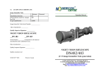
Operation Manual
LRM 2000PRO
LASER RANGE FINDER MONOCULAR
Newcon International ltd. © 2005
Printed in Canada
In USA: 3310 Prospect Ave. Cleveland, OH 44115
In Canada: 105 Sparks Ave., Toronto, ON M2H 2S5
IMPORTANT INFORMATION
Read prior to activation
You have just purchased a complicated electronic device. To operate
it properly, please read this manual carefully. Here are some
common precautions that must be noted.
• NEVER subject the unit to impact while operating or being transported
• NEVER transport the unit without the case
• NEVER disassemble the unit. This device contains high voltage
components, which may be hazardous to you!
• NEVER reverse the polarity of a battery
• ALWAYS remove batteries when not in use for a long period
• ALWAYS store in a warm dry place when not in use
• Caution - use of controls or adjustments, or performance of
proceedings other than those specified herein may result in hazardous
radiation exposure
• Caution - the use of some optical instruments with this product will
increase eye hazard
2
10. QUALITY CERTIFICATE
The LRM 2000PRO is suited for usage.
Production date ____________________________
Serial number _____________________________
Quality Inspector signature___________________
Purchase date _____________________________
Salesman ________________________________
9. CUSTOMER SUPPORT
Should you experience any difficulties with your Newcon OPTIK
product, consult the enclosed manual. If the problem remains
unresolved, contact our customer support department at (416) 6636963 or Toll free at 1-877-398-6666. Our operating hours are 9am5pm, Monday - Friday, Standard East Time.
At no time should the equipment be sent back to Newcon
without following the instructions of our technical
support department.
Newcon accepts no responsibility for unauthorized
returns.
Features of the LRM 2000PRO Laser Range Finder Monocular
•
•
•
•
•
•
•
Latest digital circuitry allows targeting through most types of
glass
First, last or the most reflective target acquisition
Meters/Yards/Degrees/KMH/MPH display
Last 10 readings recall
Selectable reticle shape (+ or □)
Target quality indicator
Speed detector and compass
To locate NEWCON Authorized Dealer call:
Tel: (416) 663-6963 Fax: (416) 663-9065
Email: NEWCONSALES@NEWCON-OPTIK.COM
INTERNET: http://WWW.NEWCON-OPTIK.COM
The defective products should be shipped to:
In USA: 3310 Prospect Ave. Cleveland, OH 44115
In Canada: 105 Sparks Ave., Toronto, ON M2H 2S5
From International:
105 Sparks Ave., Toronto, ON M2H 2S5, CANADA
22
3
CONTENTS
1. Brief description
2. Appearance of the device
3. Supplied accessories
4. Technical characteristics
5. Operation instructions
5.1. Preparing the device for operation
5.2. Measuring procedure
5.3. Mode switching procedure
5.4. Additional display information
5.5. Test modes
6. Storage and maintenance instructions
7. Troubleshooting
8. Warranty
9. Customer Support
10. Quality certificate
4
8. WARRANTY
NEWCON OPTIK warrants this product against defects in material
and workmanship for one year from the date of the original date of
consumer's purchase, but no more than 18 months from the date of
manufacturing. If your Newcon product proves to be defective
during this period, please bring the product securely packaged in its
original container or an equivalent, along with proof of the date of
original purchase, to your Newcon Dealer. Newcon will repair (or at
its option replace), the product or part thereof, which, on inspection
by Newcon, is found to be defective in materials or workmanship.
What This Warranty Does Not Cover:
NEWCON is not responsible for warranty service should the
product fail to be properly maintained or fail to function properly as
a result of misuse, abuse, improper installation, neglect, damage
caused by disasters such as fire, flood, lightning, improper electrical
current, or service other than by a NEWCON Authorized Service.
Postage, insurance, or shipping costs incurred in presenting your
NEWCON product for warranty service are your responsibility.
Please include a check or money order made out to NEWCON
OPTIK for the amount of $15.00 to cover shipping and handling.
This covers products shipped in USA or Canada only.
21
7. TROUBLESHOOTING
CAREFULLY READ ALL THE INSTRUCTIONS BEFORE
USING!
The range-measuring mode does not work.
Press the Action button again.
Check that the battery is installed properly. Check the charge of the
battery. Replace if it is weak.
FAILURE TO OBEY THE INSTRUCTIONS WILL VOID THE
WARRANTY!
How can I clear last reading before making next measurement?
Direct the unit’s LCD reticle at the new target, press the Action
button. The new reading will appear.
1. BRIEF DESCRIPTION
There are black dots in the image.
A LCD (Liquid Crystal Display) is installed in the optical channel of
the device. Due to manufacturing imperfections in the production
process of the LCD, small black dots, scratches and other blemishes
might be visible. Those blemishes are strictly regulated for maximum
allowed number, size and location. It does not degrade the product's
performance.
Range measurement cannot be obtained.
• Check if range detection mode is activated (message READY
appears on the LCD display)
• Check if Active button is pressed
• Make sure that neither your hand or finger is blocking objective
lenses, laser emitting lens or receiver lens.
• Check if the unit is steady while you are pressing the Action
button.
20
LRM 2000PRO Laser Rangefinder Monocular is the advanced
Laser Range Finder system that provides instant distance, speed, and
angular measuring consistently and accurately. The outstanding
optics provides a sharp, clear image under all conditions. LRM
utilizes a revolutionary digital design, which outperforms any other
product in its class and price range.
The unit sends an invisible, eye safe laser beam pulses to the target.
The returned beams are captured by the digital circuitry. The time
differential allows us to calculate the distance to the target.
Incorporated digital compass measures clockwise the angle between
the optical axis and direction to the North Pole.
5
2. APPEARANCE OF THE DEVICE
6
5
6. STORAGE AND MAINTENANCE INSTRUCTIONS.
7
1
4
8
3
2
1 – Eyepiece; 2 – Objective lens; 3 – Laser emitting lens
4 – Receiver lens; 5 – M (Mode) button; 6 – A (Action) button;
7 – Body of the device; 8 – Rubber grip
Precautions: LRM is a sophisticated precision optical instrument
equipped with electronics. Therefore, it should be handled with due
care.
• Keep your device away from direct sunlight, impacts, dust,
moisture, and sudden changes of temperatures.
• Do not keep the device at temperatures higher than 65oC (149oF).
• Do not touch the optical surfaces with fingers. Doing so may
damage the anti-reflection coating.
• Avoid shocks and sharp jolts.
• Cleaning of optical surfaces is only allowed with professional
camera lens cleaning supplies.
• To clean the exterior of the device, use a soft clean cloth.
• Keep away from heating appliances and central heating.
• Remove the batteries when storing the device for long period of
time.
• Only the manufacturer can make repair works.
Fig. 1
6
19
primary 9-volt battery drops below 7.2 volt. At this point the System
is still functional but the battery should be replaced as soon as
possible. The System can operate at the voltage level above 7 volt.
11
9
1
Patent pending
The System remains in the active displaying state for 8 seconds after
pressing of any of the operating buttons and after 8 seconds it enters
the passive zero power state. Alkaline or lithium type of batteries
capable to sustain current drain up to 150 mA should be used for
powering the System.
5.5. Test modes
Mode 16 is designated to test the display. When you choose this
mode all segments and indicators will flash during 8 seconds. This
time should be enough for extensive display testing.
Mode 17 calibrates the digital compass. If the System was exposed to
a strong magnetic field or it was inoperable for a long time the
compass stops working. This is normal. To return the compass back
into working condition enter Mode 17 and rotate the System in
horizontal plane during approximately one minute. The normal
compass operation will be restored.
18
Newcon Optik
Made in Canada
10
1 – Eyepiece; 9 – Battery compartment cover; 10 – Screw;
11- Identification label
Fig. 2
3. SUPPLIED ACCESSORIES
LRM is supplied in the following assembly:
- Device
- Carrying Case
- Neck Strap
- User’s manual
- Warranty card
- 9V battery (optional)
1 pc.
1 pc.
1 pc.
1 pc.
1 pc.
1 pc.
7
4. TECHNICAL CHARACTERISTICS
1. Optics
2. Range Finder
3. Speed
Detection
4. Compass
5. Misc.
Magnification, x
Objective Lens, mm
Exit Pupil Diameter, mm
Field of View
Type of Coating
Type
Measuring Range, m
Accuracy
First, last and auto target acquisition
Meters/Yards display
Last 10 readings recall
Reticle shape
Target quality indicator
Measured speed range, kmH
Accuracy, kmH
KMH / MPH display
Measured azimuth range, degrees
Accuracy, degrees
Battery (optional)
'Low Battery' Indicator
Tripod thread
Operational Temperature Range
Storage Temperature Range
Weight without battery, g
Dimensions, mm
8
7
25
3.6
8°
Fully multi-coated optics
Class 1, eye safe, 905nm
20 – 2,000
± 1m ± 0.1%
Yes
Yes
Yes
+ or □
Yes
5 – 400
±1
Yes
360
±2
9V
Yes
¼” x 20
-25 / +50oC (-13 / +122oF)
-45 / +65oC (-49 / +149oF)
420
120 x 122 x 60
Distance measuring procedure includes instant statistical processing
of the package of single measuring sessions for each laser pulse.
Qualitative result of the statistical processing is presented on the
Display as a message TARGET REFLECTION (5).
There are four statistical qualifications of the reflected signal:
• NO TARGET REFLECTION – when a steady reflected
signal isn’t received. Numerical display shows four dashes at
the distance displaying area;
• TARGET REFLECTION LOW – when the number of
steady received reflected signals is just enough to make
acceptable conclusion about the measured distance;
• TARGET REFLECTION MED - when the number of
steady received reflected signals is in medium range and
enough to make positive conclusion about the measured
distance;
• TARGET REFLECTION HIGH - when the number of
steady received reflected signals is qualified to be enough to
make reliable conclusion about the measured distance.
The displayed statistical qualification of the reflected signal
characterizes variation in expected accuracy of measurements. At
qualification HIGH the accuracy of measurements is stated as ±1m ±
0.1%. At lower rates of statistical qualification the expected accuracy
may marginally degrade.
The display presents message LOW BAT – when voltage of the
17
5.4. Additional display information
The System operates in the setting Modes that are displayed as
follows (refer to Fig.3):
Y/M – units of measurement: yards or meters (3).
KMH/MPH – units of speed measurement: km/hour or miles/hour
(3).
° - units of angular measurement: degrees (3)
Shape of the reticle: cross shape or rectangular shape (2).
rEC1 - recall function. Upon pressing the Action button (6) (fig. 1)
the Display will sequentially show results of last 10 measurements,
starting from the latest one. The number appearing after word "rEC"
shows the number of the measurement counted back in the sequence.
When the System is in inactive state the 10 previous measurements
are stored within the System and may be recalled at any time.
cLr - clear data function: upon pressing the A button (6) (fig. 1) the
entire data on all previous measurements will be erased. This
function doesn’t change the chosen modes. You can erase the
assigned mode only by assigning a new one.
Note: After changing a battery the recall stack should be cleared
by exercising the cLr mode.
OVER 100 – indicates that gating is on. Note: This is an optional
feature not necessarily presented in your device.
5. OPERATION INSTRUCTIONS
Liquid Crystal Display (LCD)
7
6
1
8
5
9
2
4
3
1 – Low battery indicator; 2 – Reticle (cross or rectangular selectable); 3 –
Units of measurement (Yards, Meters, KMH,
MPH, Degrees); 4 – Measurement result;
5 – Target quality indicator; 6 – Laser active indicator
7 – Over 100m gating indicator (optional), 8 – Setup mode indicator, 9 –
Ready mode indicator
Fig. 3
16
9
5.1. Preparing the device for operation.
•
Unscrew the screw (10) and open battery compartment cover (9)
(Fig. 2).
•
Insert one 9V battery (sold separately) into the battery
compartment observing correct polarity.
•
Close the battery compartment cover (9) tighten screw (10).
After changing the battery, it is recommended to run the cLr
(CLEAR) mode and Compass Calibration mode (refer mode
selection procedure).
5.2. Measuring procedure
When the Rangefinder is in the passive, zero power consumption
state, the LCD Display is blank (transparent). Press the A button (6)
(Fig.1) and hold for 0.5 sec. to activate the System and the Display.
Initially the System always assumes READY mode of operation and
word ‘READY’ appears on the Display.
Pressing and releasing A button (6) (Fig. 1) at this point triggers a
measuring session, and the result will be displayed in numerical form
(4) (if measurement is unsuccessful then four dashes ‘----‘ will
appear in the numerical area). Please note that the target must be
over 20m away. The measured data will correspond to the mode
selected (see below). The units of measurement will be indicated in
the field (3) (Fig.3). If you choose more than one parameter to
measure (for instance, distance and azimuth), the measured results
will appear on the display every half second.
10
For instance, Standard1 mode implies cross reticle. If you choose
rectangular reticle (sub selection Code 10), you change the reticle
shape and leave all other parameters of this mode intact. If then you
choose Standard1 again, the reticle will turn back crosshair. The last
set mode overwrites all features that it controls.
Another standard mode is assigned to Code 8. It determines
measurement units and features as Yards, Degrees, Crosshair reticle,
Auto target selection.
All other modes determine only one parameter to measure. For
example, Code 14 allows to measure speed of the objects as
kilometers per hour. The shape of reticle and target selection will
remain the same, as they had been set before you selected the Code
14. Now you can choose a new reticle shape, still remaining in the
speed measuring mode. This example demonstrates that Codes 9-13
replace one selected feature independently, and all other codes can
replace more than one feature in a bunch.
If you want to leave the mode switching procedure without
remembering your choice, you should press and keep held the M
button for more than two seconds. This works like “Escape” key on a
computer keyboard. The rangefinder will remain in the last set mode
and return to the READY state.
Full trek of all possible modes available is depicted on Figure 4.
15
5.3. Mode switching procedure
By pressing M button (5) (Fig.1) when the System is in READY
mode, you enter the Mode selecting state. Pressing the M button
sequentially scans the Modes. The Mode under selection is indicated
on the Display by flashing of the selectable feature. The "flashing"
feature can be selected by pressing the A button (6). If you don’t find
some of the modes described below, it means they were not installed
on your system. Two modes, “Codes” and “Recall” have submenus.
You enter submenu by pressing the A button from the corresponding
mode. After that you can select the sub-item with M button and
choose your option by pressing the A button. Each time when you
make your choice, you return to the READY state.
Note: Depending on user’s requirements, the unit can be made with a
special sub selection, providing only the options required for the
particular task.
Note: Depending on the software installed the situation when the
mode is accessible but inoperable also may occur.
There is one default preset mode, Standard1 (Meters, Degrees,
Crosshair reticle, Auto target selection), which opens the mode trek.
After you have selected it, you can override reticle type and target
selection with the sub selection code.
14
If the A button is held (pressed) the System automatically enters
SCANNING mode. At this mode, the System repetitively performs
distance measuring and displaying. The time interval between
measurements is approximately 0.25 second. The maximum
measuring distance range for most objects will be about 2000 meters.
The maximum measured distance varies greatly depending on the
reflectivity of the target, weather conditions and more.
Target reflectivity depends on its color, surface finish, shape etc.
Bright colors are more reflective than darks. A polished surface is
more reflective than a rough one. Larger targets are easier for
distance measuring. Measuring a target faced at 90o (perpendicular to
the laser beams path) provides optimal results.
Bad weather conditions (rain, fog, snow, mist) will reduce the
maximum measured range. Bright sunny days will reduce
performance as well. While the unit will work through many glass
types, measuring through glass will affect the results. Hand tremor
also influences the results. Use tripod to measure distance to faraway objects.
The unit can estimate distance to up to 7 targets simultaneously. The
mode selection logic allows choosing the nearest (‘first’), the farthest
(‘last’) or the most reflective (‘auto’) target. This mechanism helps to find
correct target between bushes, wires, flakes, or, opposite, measure a
distance to wire, which hangs in front of the building wall. However, it
cannot be guaranteed that the device will always measure the needed
distance. It can happen that there will be no pulses bounced off the desired
object at all.
11
Target
type
Reticle
Azimuth
Screen display
Speed
Distance
Mode
A
A
A
M
1) Standard 1
Select this mode
M
,
,
,
Meter
Degree
Auto
Target
Go to next mode
A
2) Codes
A
A
Code1
Select this mode
A
Code2
Select this mode
A
Code3
M
Code12
Select this mode
A
Meter
Code13
A
Yard
A
Go to next mode
Code14
Degree
Select this mode
A
Go to next mode
M
Code15
M
Code16
M
Code17
M
A
4) Recall
Not used
Compass calibration
Go into submenu
A
Select this data
A
Select this data
A
Go to next mode
Select this data
Select this data
5) Clear
A
Code9
A
Code10
A
M
Go to next data
M
Go to next data
Rec9
M
Go to next data
Rec0
M
Rec1
Rec2
...
A
Not used
Select this mode
MPH
Display self-test
Go to next mode
M
Code8
Yard
Go to next mode
Not used
A
KMH
Go to next mode
Not used
Select this mode
Meter
Go to next mode
Select this mode
M
Auto
Targe t
M
Go to next mode
Select this mode
M
First
Target
M
Go to next mode
Select this mode
Go to next mode
Last
Target
M
Go to next mode
Select this mode
Go into submenu
Go to next mode
Code11
Select this mode
M
Go to next mode
Yard
Degree
Auto
M
A
Clear memory
“ Action”
button
Use previous
settings
Target
M
Go to next mode
M
Select this mode
Go to next mode
Fig.4 Mode switching trek
M
“ Mode”
button