1
4MinX
Portable Mixer/Recorder
User manual
AETA AUDIO SYSTEMS
18-22, avenue Edouard Herriot – Kepler 4 – 92350 Le Plessis Robinson – FRANCE
Tél. +33 1 41 36 12 00 – Fax +33 1 41 36 12 69 – Web: http://www.aeta-audio.com
55 000 061 - E
4MinX - User manual
Specifications subject to change – All rights reserved by AAS
July 12
55000061E_4MinX_en.docx
Index
1.
2.
Technical Characteristic ....................................................2
Functions .............................................................................3
2.1. Audio Inputs ........................................................................................ 3
2.2. Analog outputs ..................................................................................... 8
2.3. Monitor ................................................................................................ 9
2.4. Internal alignment signal generator ................................................... 12
2.5. Intercom / Slate microphone .............................................................. 12
2.6. Alimentation ...................................................................................... 12
3.
Operating mode – Detailed description ..........................14
3.1. Switching on and off .......................................................................... 14
3.2. General principles .............................................................................. 14
3.3. Menu structure ................................................................................... 15
3.4. Menu : « Audio » ............................................................................... 17
3.5. Menu : « Recording » ........................................................................ 19
3.6. Menu « Settings » .............................................................................. 27
3.7. Menu : « Tools » ................................................................................ 30
3.8. Recording interface ............................................................................ 32
3.9. Recording........................................................................................... 33
3.10. Player ............................................................................................... 33
3.11. Shortcuts .......................................................................................... 35
3.12. Using the L/R M/S transcoding .................................................. 36
4.
Technical Specifications ...................................................39
4.1. Microphone/Line inputs ..................................................................... 39
4.2. Line input ........................................................................................... 40
4.3. AES inputs ......................................................................................... 40
4.4. "Line Out" balanced analog outputs .................................................. 41
4.5. "Line Out" unbalanced analog outputs .............................................. 42
4.6. Digial outputs .................................................................................... 42
4.7. Headphone output .............................................................................. 43
4.8. "Direct I/O" interface ......................................................................... 43
55 000 061 - E
4MinX - User manual
4.9. "EXT I/O": Interface for RF transmitters/receivers ............................ 45
4.10. Power supply .................................................................................... 46
4.1. Time Code .......................................................................................... 46
4.2. Dimensions and weight ...................................................................... 47
4.3. Environmental .................................................................................... 47
4.4. Options ............................................................................................... 48
5.
Annexes ............................................................................. 49
5.1. Overview of connectors and front panel elements ............................. 49
5.2. Block diagram .................................................................................... 52
5.3. Level maps ......................................................................................... 54
5.4. Filters.................................................................................................. 55
5.5. Limitor ................................................................................................ 56
5.6. Accessories ......................................................................................... 57
Revision:
C – Build on firmware V1.4
D – Build on firmware V1.5
E – Build on firmware V1.6.1
4MinX - User manual
55 000 061 - E
Introduction
4MINX is a portable mixer specially designed for outside recording.
4Minx is new kind of product on this market. It can be use as a traditional
mixer, but can be use as a multi tracks recorder. In same time, it can manage
digital audio treatment in real time.
This equipment is suitable for sound production, with its remarkable audio
features and its full compatibility with « M/S » and « surround » systems.
4Minx have 4 Mic/Line inputs, with all power phantom and limitor, 2 digital
inputs AES3. Digital inputs support the normalization AES42 for digital
microphones (10v phantom power).
4Minx has many outputs, 6 analog channels and 6 digital channels AES3.
The routing capability for each input and each output give complete liberty to
the user.
The multi tracks recorder can grow up to 8 tracks on SD/SDHC card and can
make a backup on external USB disk. You should use SD/SDHC card Class 10
or similar to avoid problems.
A project management included in the unit gives the opportunity to make many
sounds recording without problem.
4MinX has a keyboard and a 3” TFT high quality display, offer a simple and
nice user interface. On 4Minx the user can set its own mixer interface in regards
inputs and outputs need in his configuration.
To start a work quickly, you can read the quick start delivery with the unit. It
will provide you all details step by step to start a record.
55 000 061 – E
4MinX - User manual
1
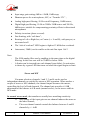
1. Technical Characteristic
Light weight and small dimensions (1.9 kg, 260 x 75 x 195 mm)
4 Mic/Line transformerless inputs, very low noise (-128dBu)
Adjustable input gain, 10 dB steps, 0 to +50 dB
High-pass filters on each channel
Maximum overall gain: 90 dB, useful for dynamic and ribbon
microphones
Maximum input level: +19 dBu without pad
Input headroom: 40 dB, independent of input stage gain
LED for overload warning on each input channel
Fast limiter on each input, 40 dB operating range, with LED indicator
Stereo or M/S coupling on inputs 1&2 et 3&4
Stereo M/S encoder/decoder on inputs 1 & 2, 3 & 4
4 main line outputs, maximum level adjustable from -9dBu to +22dBu
2 return or auxiliary line inputs, maximum acceptable level adjustable
from -9dBu to +22dBu ( for 0dBFS)
separate Stereo M/S encoders/decoders, for monitoring
2 unbalanced outputs (level 6 dB below the balanced outputs)
3” QVGA TFT screen with adjustable brightness, displaying large
scale bargraphs (50 dB dynamic range)
High performance headphone amplifier, with selectable source and
listening mode
Long operating range on Li-Ion DV battery and charger inside
3 AES3 digital outputs, stereo, 24 bits, up to 96 kHz
2 AES3 digital inputs with phantom +10V for AES42 microphones
with sample rate convertor.
2
4MinX - User manual
55 000 061 - E
2. Functions
The functions of the analog and digital mixer are shown on the functional
diagram that can be found in annex Erreur ! Source du renvoi introuvable.,
“Erreur ! Source du renvoi introuvable.”. On next paragraph, we will
describe in detail all inputs and outputs of the 4MinX
2.1. Audio Inputs
2.1.1. Input “Mic/Line”
Each of these four inputs is available on a 3-pin female XLR socket, and
is electronically balanced. Each input support 48V phantom power or T12
power. If no powering is active, unbalancing an input has no negative impact on
the performance.
. Each input has its own volume control on the front panel, generally
named « fader ».
Specificities:
- Inputs 3 and 4 can also be fed from the “EXT I/O” socket, in which
case no microphone powering is available
- Input 1 and 2 can stand very strong audio levels thanks to a 20 dB
attenuator. When it is enable, the input level can grow up to +39dBu.
Functions of the “MIC/Line” inputs
The following functions are available on each input, via a selection in the menu:
55 000 061 – E
4MinX - User manual
3
Input stage gain setting, 0dB to +50dB, 10dB steps;
Phantom power for a microphone, 48V, or “Tonader 12V” ;
Analog high-pass filtering, 50 Hz cut-off frequency, 18dB/octave;
Digital high-pas filtering, 50 Hz to 200Hz 12dB/octave and 300 Hz,
6dB/octave, suitable for compensating proximity effects in directional
microphones
Polarity inversion (phase reversal)
Fast limiting, with “soft knee”;
Routing to Left or Right bus, or Center (i.e. L and R), with pan-pot, or
not routed at all
The “risk of overload” LED begins to light at 12 dB below overhead.
Attenuator ( 20dB ) can be enable on the mic/line input 1 & 2
Note:
-
The 50Hz analog filter can be enabling in the same time as the digital
filtering. In this case rate will be 32dB/Oct below 50Hz.
A limiter can be inserted into each channel (post-fader). Its activation
is shown by a green LED that turns red when the signal begins to limit.
-
Stereo and M/S
Via menu selection, channels 1 and 2, 3 and 4 can be used as
independent channels or coupled for stereo or M/S operation. When used as a
couple of stereo or M/S channels, the channel impair becomes the master,
controlling the level of both channels. The channel pair provides +/-5dB
adjustment of the balance in L/R mode (normal stereo), or the stereo width in
M/S mode.
In normal stereo mode, the transducers usually have matching sensitivity:
4
Any change of the input gain on one channel induces the same on
the other channel;
The even channel control controls the balance between L and R
channels by +/- 6dB
4MinX - User manual
55 000 061 - E
Input odd is routed to the Left bus, input pair is routed to the
Right bus
The even input is routed on the mix down Left and the odd on
the mix down right. But, Over writing these routing remains
possible!
In “M/S” mode the transducers often have different sensitivity:
The input gain adjustment is kept separate for channels odd and
even,
The odd channel control adjust the couple level
The event channel control adjusts the stereo image width. In the
center detent position, a coherent couple should provide a
normalized 110° angle
Whenever inverting the phase of channel even, after decoding
from M/S to L/R the stereo image is reserved LR
Manual routing is inhibited and the signals are routed and
decoded as follows:
Input impair is the “M” signal, input pair is the “S” signal;
Input impair + Input pair (M+S) is routed to the Left bus;
Input impair - Input pair (M-S) is routed to the Right bus.
Limiters
A limiter can be inserted into each channel, after the channel fader. This is a
fast limiter with a dynamic range wide enough to stand the 40 dB overhead of
the input stage. The activation of the limiter is shown by an LED.
As long as the signal level stays below the limiter threshold, little effect is seen
on the signal. When the limiter is triggered, its output stays 6dBFS below the
A/D converter clipping level for up to 40dB input overdrive.
It can thus be seen as a “safety” limiter, that may be left active all the time!
The threshold can be adjusted through the menu from –12dBFS to –3dBFS
55 000 061 – E
4MinX - User manual
5
Note: In case of use specific coupling the limiters are coupling together, which
is the required mode for applying simultaneous and identical gain reduction to
both channels in « stereo » and M/S modes, in order to preserve the coherence
of the stereo image.
2.1.2. Line inputs/return
Two inputs are available on a 5-pin female XLR socket, and are electronically
balanced. It is possible to unbalance an input without negative impact on the
performance. Each channel has its own maximum level adjustment in the menu
from -9dBu to +22dBu (for 0dBFS). Theses inputs can be use as a return from
video camera but can be use as more analog entries for the mix down or the
recorder. It is possible to have a fader control on each input through P1 to P4. In
this case, we provide you 15dB more gain.
2.1.3. Embase “EXT I/O”, Récepteurs HF
The “EXT I/O” socket is available for the connection of an optional
extension box. This device can be used to interface 4MINX with radio
transmitters and/or receivers.
When the extension device is plugged into the “EXT I/O” socket, the
mixer can use, for channels 3 and/or 4, inputs from the EXT I/O socket instead
of XLR inputs 3 and 4. In this case NO microphone power is apply on these
inputs.
The extension device feeds these inputs with two balanced signals. For
safety, no microphone powering is inserted into these inputs on the EXT I/O
socket but all others settings are the same.
On this interface, you have 2 asymmetrical outputs. Theses outputs are
described on the need paragraph.
Note: A 9V/ 600mA power supply is available on the connector.
6
4MinX - User manual
55 000 061 - E
2.1.4. AES Inputs
4MINX can accept AES3 digital audio input on its « Dig. In » (XLR 3 pins).
Signals can be routed or mixed in the bus as others inputs or send to any
outputs.
The input 1&2 can be used to synchronize the 4minx on another machine. This
feature can be set in the synchronization menu, it is necessary to specified in the
same menu the frequency of the AES signal. Both digital inputs are using a
sample rate convertor when you are in master mode.
Note: Don't forget to set the right sample frequency on the synchronization
menu when you want to use the AES input as synchronization
55 000 061 – E
4MinX - User manual
7
2.2. Analog outputs
2.2.1. Main outputs “Line Out”
4Minx have 2 stereo line outputs on XLR 5 pins. By menu, you can set
source for each channels between all inputs, bus, monitoring.
The signals are electronically balanced; they can be unbalanced with no
impact on performance, as long as the level stays below +19dBu.
The maximum output level (which corresponds to the maximum digital
level, 0dBFS) is adjustable via the menu, from -9dBu to +22dBu.
Also via the menu, a 40dB attenuator can be inserted on each output
channel, so providing a “microphone level” signal.
2.2.2. Unbalanced “Line Out”
The same signals of the first “stereo” line output as found on the XLR5M
socket are also fed to a 3.5mm stereo mini-jack socket. These signals are
unbalanced, and their level is 6dB below those on the balanced XLR5M .Their
typical use is for linking the mixer to a semi-professional recorder (Mini-Disc,
cassette, DAT…) or connecting a second headphone
2.2.3. Analog outputs for radio transmitters
The L and R mix buses or any inputs can output on the « EXT I/O »
socket (on the left side of the unit), with a separate adjustment of the maximum
level for each channel from -20dBu to +10dBu, which allows a suitable
adaptation to most radio transmitters. These outputs are asymmetrical.
2.2.4. Digital outputs
4MINX delivers 24-bit stereo digital outputs; it is possible (via the menu) to
select either a “Pro” mode or “Consumer” mode, depending on the type of
equipment the signals are fed to.
A balanced and transformer isolated AES output (110Ohm impedance) is
available on the “Dig. Out” socket. It is possible to connect this AES output to a
SPDIF input through an adaptor cable (optional: see Annex).
8
4MinX - User manual
55 000 061 - E
2.3. Monitor
2.3.1. Display screen
The display screen of 4MINX is a 3” color QVGA TFT display. This
technology features a very wide viewing angle and fast response time. The
display brightness is adjustable, it has latest technology for a perfect outside
used.
On the main screen:
- The monitoring audio level of left and right signals are showing at the
bottom of the display
- Just over them the level of the four mixer channels is shown.
-
-
Levels are displayed on large scale bargraphs covering -50dBFS to
0dBFS.
By menu you can set 4 metering level threshold (Minimum, nominal,
yellow, red)
They are measured with fast PPM ballistics.
In addition, peaks are held on for about 4 second (“peak-hold”
function)
An “OVL” icon shows up whenever the level reaches -3dBFS or more.
Input number are display in red when you enable a coupling between
us (when 2 stereo or M/S coupling are selected, the second is show in
blue).
If you select pre fader by menu for the input, a ‘P’ is display
55 000 061 – E
4MinX - User manual
9
2.3.2. Configuration
The « Monitor » function allows the selection of signals inside 4MINX for
displaying their levels on the screen and monitoring them on headphones
Just by pressing monitor key and moving the rotary, you can select the
following signal sources for monitoring:
Input 1 to 4, in post or in pre fader
Channel couple : AES 1&2, AES 3&4
Return/Line In couple of signals
Bus
…
Note: The selection can
be affected on one of
function key ( F1 to F4)
by a press on it.
A second bank is
available by pressing the
Shift
You have a total of 8
monitoring presets
Note: When presets are
available, you should
press twice the
monitoring key to access
to this menu.
Note: press the monitoring key to swap between sources and mode.
10
4MinX - User manual
55 000 061 - E
To set a shortcut key, you have just to press it under this display. The current
selected source and mode will be saving on this shortcut key.
Example : Set preset F1
2.3.3. Headphone monitoring
The headphone can be plugged into a stereo 6,35mm jack socket. By pressing
twice the monitoring key and vertically moving the cursor with the rotary, the
monitor mode can be selected among the following:
L/R : Normal stereo listening ;
L/L: left signal on both ears ;
R/R: right signal on both ears ;
L+R : mono sum (L+R) on both ears;
(useful for mono compatibility and phase coherence checking)
M+S : M+S sum (normally left signal) on both ears ;
M-S : M-S sum (normally right signal) on both ears ;
M/S: listening of encoded signals (sum and difference)
The L/RM/S matrixing is used for example to listen a conventional stereo
signal (L/R) when monitoring M/S microphones, or when monitoring outputs
that have been M/S encoded.
Alternatively, when the mixer is operated in normal stereo mode,
encoding the signals for monitoring can be used to check the stereo
correlation, by comparing the relative amplitude of the M and S signals
55 000 061 – E
4MinX - User manual
11
2.4. Internal alignment signal generator
An integrated double oscillator can deliver a sinusoidal 1 kHz on the left and a
400Hz on the right to outputs. This can be used to align analog equipment
connected to these outputs. This signal is activated on all outputs (analog and
digital).
The peak level of the generator is -18dBFS (EBU digital reference level) by
default but can be adjusted by menu from (-12 to -20dBFS).
A function key can be set to have a direct access to the
2.5. Intercom / Slate microphone
A microphone is integrated in 4MINX’s front panel; its amplified signal can be
inserted into the analog/digital outputs (replacing the normal audio signals). See
audio routing, Slate.
A function key can be set to have a direct access to the feature.
2.6. Alimentation
4MINX operates from Li-Ion DV battery type NPF-9x0. The integrated charger
can recharge it from an external DC supply in less than 7 hours (depending of
the battery capability).
The DC/Bat LED becomes red to show the proper operation of the internal
charger. This LED becomes green at the end of the charge. If you don't want to
charge the battery, you should use a dedicated power cable without connection
on the Charger dc input pin (See connectors paragraphs), which may be
desirable e.g. if the external source is itself derived from a battery pack.
4MINX can operate from an external source of 8 V to 18 V DC voltage.
4MINX draws constant power from the external source when the voltage
changes. 10V minimum is need for charging.
The same LED becomes green to indicate the presence of the external
power source. 4MINX switches automatically between its internal battery and
12
4MinX - User manual
55 000 061 - E
the external source, without any noise (priority is given to the external source
when it is available!)
The low battery level can be adjusted by menu from 6,4v to 7,4v. When this
threshold is reached, a warning message is display on the screen and the
battery icon is set in red.
Whenever the battery voltage goes down to 6.4 V, 4MINX is automatically
shut off. This prevents damaging the battery by discharging it too deeply.
4MINX’s power consumption and hence its battery range depend much on the
operating conditions, such as the number and powering mode of the
microphones, headphone impedance and listening level, etc.
However, as an example, starting with a full charged battery, 4MINX will
operate for at least 7 hours (Sony NP-F970) with dynamic microphones
(including ribbon microphones) and a 600 headphone. In such condition,
4MINX draws less than 500mA from a 14.4V external source.
4MINX draws a near-constant power (not a constant current) from the external
source when the voltage varies
55 000 061 – E
4MinX - User manual
13
3. Operating mode – Detailed description
3.1. Switching on and off
Hold down the “Esc” button for more than 2 seconds; the screen will light up
and display the AAS logo after few seconds and after the application start.
To switch off the unit, you should go in the menu tools, power down;
Like that, you will preserve the integrity of the systems and limits the risks to
have defective audio files.
Note: It is possible to switch off the unit by holding down the “Esc” button for
more than 10 seconds. This should be use only for emergy used.
3.2. General principles
To enter the menus, push (just shortly this time!) the “Esc” button. The main
menu is then displayed. Pressing again the “Esc” button brings you back to the
normal meter display mode
You can navigate inside the menus and across lists using the rotary.
To change an item, first move towards it using the rotary until the item is
highlighted; then select the item by pressing the “OK” button or push down the
rotary. Change the selected item or value using the rotary, and press again the
“OK” button to confirm the change.
Press the “Shift” button to leave a menu from one level
Press the “Esc” button to leave a menu; repeat the press to return to the normal
meter screen
In some case, F1 to F4 keys can be used as function key
14
4MinX - User manual
55 000 061 - E
3.3. Menu structure
The menu is divided in 4 sections
Audio configuration with
« Audio input » : Analog and digital inputs settings
« Audio Output » : Analog outputs settings
« Coupling » : analog input coupling between input 1 to 4
« Routing » : Output routing & bus mixing
« P1-P4 » : P1 to P4 potentiometers function
« Master » : Master gain level
« Mixdown limiter» : Limiter/Compressor configuration
Recordings
« Project management » : To create, delete and modifie a project
« File management » : Configuration of recorded files
« Filename template » : template of recorded files
« Meta Data » : Management and entry of medata for BWF files
« File format » : Configuration of number of bites in the files
« Pre-record » : pre record time configuration
« Backup false take » : Enable false take backup
55 000 061 – E
4MinX - User manual
15
« Backup to USB »: Enable the backup of the current working day
on an USB disk.
Settings
« Synchronization » :to set synchronization source and the sample
rate frequency
« Tone generator » : Adjust the tone generator level
«Snapshots« : Manage snapshots (user memories )
« Function keys » : Assign feature on assignable F1 to F4 key
« USB keyboard » : keyboard language selection
« Time code » : Set all time code configuration: mode and video
rate
« Display settings » : Configuration of bargraphs and brightness
adjustment
«Recording BIP» : Enable/disable BIP on record start and stop
« Date » : To change the system date
« Time » : To change the system hour
« Keyboard auto lock » : Automatic lock of the - and + keys after
10s
Tools
« Power down » : to switch off the unit
« Format media » : to format the SD card
« Update firmware » : update the firmware from the SD card
16
« Sleep» : to put the 4Minx in Sleeping mode
« Eject media »: Un mount SD card before removing it from its
holster. NEEDED TO AVOID PROBLEMS
« Reset settings » : Load factory configuration
« Import » : Load settings and projects form the SD card
« Export » : Export settings and projects to the SD card
« Warning Threshold» : Set threshold warning level of the battery,
the external DC level and the disk space
4MinX - User manual
55 000 061 - E
About
Show system information : version, configuration, IP address
Shortcut list : Show shortcut key features
3.4. Menu : « Audio »
-
3.4.1. Menu : « Audio Inputs »
For each microphone 1 to 4
o The microphone gain can be set from 0 to +50dB by 10dB
step
o An analog filter at 50Hz 18dB/Octave can be enable
o A limiter can be enable
o A 48Volts phantom power can be enable or a Tonader 12V.
o The phases can be inverted
o Specific settings for microphone input 1 and 2 : An 20dB
attenuator ( PAD ) can be enable.
o Specific settings for microphone input 3 and 4 : The input
connectors can be switch from standard XLR 3 pin to the
MiniCon 12 pins
-
For the line inputs (1 and 2)
o The maximum level can be set between -9dBu and +22dBu
-
For each AES inputs ( 1&2 and 3&4 )
o 10V phantom poser can be enable ( AES42 normalization)
o A fixed gain can be set between 0dB to 36dB by 6dB steps
-
« Limiter Threshold » : Adjust the microphone limiter threshold
between -3dBFs to -12dBFs, -6dB is the minimum value to accept the
full dynamic input range.
55 000 061 – E
4MinX - User manual
17
3.4.2. Menu : « Audio Output »
-
For each line from 1 to 4
o The maximum output level can be set between -9dBu to
+22dBu
o A 40dB attenuator can be added.
-
For each Extended outputs on I/O connector (MiniCon)
o The maximum output level can be set between -20dBu to
+10dBu
o « AES out mode » : AES format : « Pro » or « Consumer »
3.4.3. Menu : « coupling »
In this menu you can select microphone coupling between:
For 2 inputs: Stereo or M/S coupling on inputs 1&2 or 3&4
For 3 inputs: Double M/S, inputs 1&2&3
For 4 inputs: Link between 1-2-3-4 or SoundField ( option for the SPS200
microphone)
3.4.4. Menu : « Routing »
Under this menu, we can set inputs sources mixing together in the
stereo bus (Mix down) and in the auxiliary 2 channel bus « AUX »
Note: The master has no effect on the auxiliary bus. An automatic attenuation is
made depending of the number of selected sources.
For each analog and digital output you select one of any inputs, the mixing bus,
monitor or play back sources
Last point, you can specify on witch outputs the slate will be send.
18
4MinX - User manual
55 000 061 - E
3.4.5. Menu : « P1-P4 function »
Under this menu, you can assign many features on the P1 to P4 potentiometers
1.
2.
3.
You can have a panpot feature on the microphone input 1 to 4.
When you select this feature, the selected input is automatically
routed in the mix down with panpot. When you disable it, the
selected input is routed in L&R in the mix down.
You can configure a gain adjustment on the input line 1 & 2, both
can be coupled on a single potentiometer or separated on 2
potentiometers. The line input accepts a maximum level of +
24dBu and gain adjustment covers a range of + 15dB to-90dB
You can configure a gain adjustment on the AES input 1&2 or
3&4. Each couple can be coupled on a single potentiometer or
separated on 2 potentiometers. The gain adjustment covers a range
of + 15dB to-90dB.
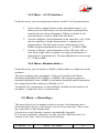
3.4.6. Menu « Mixdown limiter »
Under this menu, you can enable or disable a limiter and/or a compressor on the
mixdown.
The user can adjust many parameters. At first you should set the limiter
threshold (Adjustable from -2dBFS to -20dbFS), after that the compressor
threshold (adjustable from -40dBFS to the limiter threshold) and last parameter,
the compression of the compressor (Disable to 1:6).
To simplify the configuration, we have defined 3 profiles for the reactivity of
the limiter / compressor: Slow, normal and fast
3.5. Menu : « Recording »
This menu allows you to manage records on a shoot. Each shooting can be
associated with a project, in the project you can create work days. These work
days can follow or not calendar days.
At each new record, the take counter is automatically increased.
If you want to split into "subgroup" records, can select different scenes. In
contrast to the "take", there is no auto-incrementing
55 000 061 – E
4MinX - User manual
19
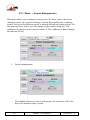
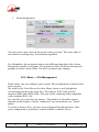
3.5.1. Menu: « Project Management »
This menu allows you to manage your projects. We have 3 parts, the first to
manage projects, the second to manage working days and the last to manage
scenes. Access to the different parties is making through the function keys. Via
the main interface, below, you can change project and working day. The
validation of a project is necessary to enable it. The validation is done through
the function F4 key
1.
-
Project management
This module allows to create a new project, the work day will be the
day of the machine (date system)
20
4MinX - User manual
55 000 061 - E
-
-
2.
You can destroy a project. But to destroy the current project, it is
necessary to select another project before. Only information related to
the project is destroyed but not audio files are destroyed.
You can generate a report of the complete project in HTML and CSV
format on SD card trough the Sound report menu
Work day management
- This module allows creating a new work day with the date system
- You can destroy a workday. ATTENTION: all information and
AUDIO files of this day will be destroyed. It is the only way to destroy
audio files.
- Can generate a report of the day's work in HTML and CSV format on
SD card via the Sound report menu.
55 000 061 – E
4MinX - User manual
21
3.
Scene management
You can create a new scene in the project when you want. The scene index is
not related to working days. It increments regardless
For all modules, the navigation between the different drop-down lists is done
through the encoder as in menus. The activation of the Ok allows entering and
getting out of the various fields. The Esc key cancels any changes.
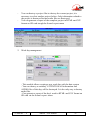
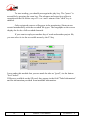
3.5.2. Menu : « File Management
In this menu, you can configure your records. This configuration is linked to the
active project.
We work by file. Each file can be either Mono, stereo or well polyphonic
(several mono tracks in the same file). The files are WAV files with the
extension BWF and iXML fields. This type of file remaining fully compatible
with a standard WAV file.
For each file, you can select the sources. The number of selectable sources
depends on the number of tracks "authorized" on your machine (see "About"
menu)
To create or destroy files, you have at your disposal the function keys. Once
your configuration is performed, it must validate it with the F4 key
.
22
4MinX - User manual
55 000 061 - E
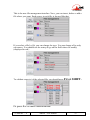
This is the new file management interface. Now, you can insert, delete or add a
file where you want. Each source in each file is showed like that.
If you select a file by Ok, you can change the type. You can change all or only
one source. You should use the rotary do go on the field whose be modify
(displayed in red )
To validate source(s) of the selected file, you should press F4
or SHIFT.
Or press Esc to cancel modification.
55 000 061 – E
4MinX - User manual
23
If the file is not valide, you have a ‘---‘ in the sources field.
3.5.3. Menu : « Filename template »
Through this menu, you can change the root of the file name. You have at your
disposal 3 fields. For each field, you can select information of the project for
example the name of the project, the name of scene…
The file will have the following name:
[Field 1]_[ Field 2]_[ Field 3]-[scene index]_[Take index]_[File number]-[Split
file index].wav
3.5.4. Menu : «Meta data »
In this menu you can enter a name for the current scene, notes on the current
scene, put a machine name in the sound report and also enter a user name.
24
4MinX - User manual
55 000 061 - E
To entry data you have at your disposal a virtual keyboard if you haven’t an
USB keyboard connected.
Virtual keyboard:
- The letter selection is made via the encoder
- The validation of the letter is made via the OK button.
- You can change the position of the cursor in the text with the keys
and
.
- The Stop key inserts a space in the text.
If you use a compact keyboard, you can enter accented characters in notes field
Note: When the "Automatic note" option is enabled, at the end of each
recording, the note entry appears. This allows modifying quickly the note
between each takes. You can at the same time mark your scene as good via the
F1 key ("circled").
You can specify the nature of the record via the menu "Recording type". This
information can be used in the name of the file
A canvas is available in this menu too. The canvas has the following format:
sequence number + letter-scene-take. The canvas is automatically incremented
at each new take and it is resetting on a new scene creation. The canvas can be
used also in one field of the recording file name.
55 000 061 – E
4MinX - User manual
25
3.5.5. Menu : «File format »
You can specify the number of bits of the BWF file, 16-bit or 24-bit files in this
menu
3.5.6. Menu : «pre-record »
4minX supports up to 10s of pre-record, based on the number of tracks and
sampling frequency. Pre record is automatic reset on each configuration change.
The total duration of your records will be increased by the value of the selected
pre-record.
3.5.7. Menu : «Backup False take »
If you enable this function, false take will be saved in a "trash" sub directory of
the project. The files keep the same name indexed by a '_x'. If you make several
consecutive false take on the same index, we add an another '_x' on older files
3.5.8. Menu «Backup to USB »
If you connect a memory key or an external hard drive on the USB port, you
have the opportunity to make a backup of audio files of the current day. The
transfer is done in background. You can stop the transfer and resume at a later
date, where you are.
The State of the "backup" is shown by icon in the main window instead of the
external USB drive icon
.
Symbol red round: backup running
Symbol red pause: backup in pause
Symbol yellow exclamation Point: problem,
Symbol green round: synchronization made
Note: It is strongly recommended to use the mini USB connector to reduce the
transfer time.
.
26
4MinX - User manual
55 000 061 - E
3.6. Menu « Settings »
3.6.1. Menu : « Synchronization »
In the "Mode" menu, you can choose the mode "Master" (operation on the
internal clock) or select an external sync mode: AES or a word clock (Time
code Option)
In the "Frequency" menu, you can select the sampling rate frequency from
32kHz to 96 kHz
Note: It is imperative to select same sampling rate as the external source of
synchronization for the proper functioning of the machine.
55 000 061 – E
4MinX - User manual
27
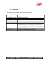
3.6.2. Menu : Time Code ( Option)
In this menu you can set the Time Code mode of operation:
- Off: all the records begin to 0h0m0s
-Free Run: Time code runs independently on its current value
-Ext TC: 4MinX following continuously an external code, including judgment
time
-Ext Tc / cont: 4MinX synchronizes to an external TC and continues to run the
TC even if the source is disconnected.
You also have the option to configure video format which is associated with:
23.976, 24, 25, 29.97, 30, 29.97 drop or 30 drop frames per second.
Set Time Code menu specify its value for the "free run" mode or when 4MinX
is used as a generator of time code. An adaptation of LEMO5points to two
sheets BNC cable is available as an option.
Led bicolor on the right side of the 4minX gives you the State of the Time Code
module configuration
1 second
1 second
Time code not set
Time code set
Reader mode
Low Voltage (TC not set)
Low Voltage ( TC set)
“Recovery” mode
28
4MinX - User manual
55 000 061 - E
3.6.1. Menu : « Snapshots »
You can create configurations memories. All configurations related to audio
and audio files will be stored in each memory.
3.6.2. Menu : « Tone »
Allows to adjust the level of the tone generator between -6dBFS to -20dBFS
3.6.3. Menu : « Display »
The menu "Brightness" allows both adjust the brightness of the screen and all of
DEL present in the face before.
The "Metering thresholds" menu allows setting the threshold for each LED of
the bargraph. These same settings are used for the display of the levels on the
TFT screen.
The "Bargraph mode" menu offers you the possibility to change the display
mode of the audio levels on the screen between VU mode and dBFS mode.
In VU mode, the 0dB level corresponds to the threshold of the yellow led.
The "Bargraph count" menu allows you to benefit of 4 additional bargaphs in
mode "full". 4 Additional bargraphs are blue instead of green.
The « Bargraph display » menu allows you to select between 2 mode the
bargraphs sources ; The ‘Tracks’ mode follow file/tracks configuration and teh
‘User’ take in care selection made on “Bargraph sources" menu.
The "Bargraph sources" menu offers you the possibility to customize the
sources of 8 bargraphs on the screen.
Note: the 4 mic/line inputs bargaphs led show the post fader level (cannot be
changed)
3.6.4. Menu : Function keys
This menu allows you to configure function keys for the “recording” mode.
You can assigned 2 functions by touch, through the use of the "shift" key before
pressing the function key.
Here is a list of the available functions:
- For mic/line inputs
o Gain, filters, phase, Limiter, solo
55 000 061 – E
4MinX - User manual
29
-
-
Meta data
o Note
o Scene name
o Type of take
o Canvas
Other functions
o Slate, Tone,…
3.7. Menu : « Tools »
3.7.1. Menu : Power down
It is imperative to go through this menu to turn off the machine if you don’t
want to lose settings and configurations.
3.7.2. Menu : Sleep
This menu allows putting the 4Minx in standby. In standby, the consumption is
reduced to 1.5W. All microphones power are cut and the 9V for the wireless
transceivers et receiver is turn off.
By pressing during 2s the Esc key you return to the normal operating mode in
10s
3.7.3. Menu : Eject media
TO AVOID ANY PROBLEM WITH THE FILE TABLE ON THE SD CARD,
IT IS IMPERATIVE TO PASS THROUGH THIS MENU BEFORE
REMOUVING THE SDCARD OF ITS HOSTER
3.7.4. Menu : Format media
Through this menu, you can format quickly your SD card with FAT32 file
system.
3.7.5. Menu : Reset settings
This action will destroy all configurations registered in the machine.
You can also, via this menu, return to the "factory configuration".
30
4MinX - User manual
55 000 061 - E
Note: restart requested after this action!
Note: The audio files in the memory card are not destroyed!
3.7.6. Menu : Import/export configurations
With these two menus, you can import and export your projects and your
configuration of machine on the SD card.
Note: A reboot of the machine is necessary after importing a configuration.
Note: Via the export menu/debug, you can retrieve all the information relevant
to analyze problems on the SD card directory
3.7.7. Warning
You have 3 sub menu to set warning threshold:
- Warning threshold for the NP-F battery
- Warning threshold for the external DC power
- Warning threshold for remaining SD card disk space.
3.7.8. Update
Check on the SD card an update file and launch the update if it is found
55 000 061 – E
4MinX - User manual
31
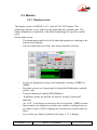
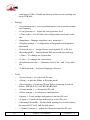
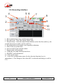
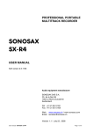
3.8. Recording interface
4
5 6
3
7
8
9
2
10
11
1
1 : Show monitoring source and listening mode
2 : Recorder state : Stop, Recording, Pause, play
3 : Function keys : show the name of the function on the first line and in [], the
second function accessible with the shift key
4 : Synchronization and sample rate frequency indication.
5 : Time Code or system hour
6 : Last recorded scene and take index.
7 : Project name and work day
8 : USB disk icon and USB keyboard icon
9 : SD/SFHC card information
10 : Files/tracks status
11 : 4 mic/line configuration status for the selection function key (ie :
microphone ). Chx change to blue when 48V is selected and change to red for
T12.
32
4MinX - User manual
55 000 061 - E
3.9. Recording
To record, a project must be validate (by default "default" project), and having a
configuration files valid ( by default “Mix down”). This information must be
available on the work screen (above: point 7 and 10).
To start a recording, you should press "REC" key. The first pressure, the
recorder is set to "READY", and it waiting for a confirmation by a second
"REC" press.
The record can be put in pause, by a "REC" press and resume by another
“REC” press
Recording is stopped by a double "STOP" press.
The current time or time code and recording time are refreshed every second.
There is also the duration available for a new record (See part 9), ensuring that
the remaining disk space is sufficient.
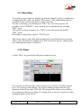
3.10. Player
A short “Play” key press show the player module screen.
You can browse between take in the current scene via the F1 and F2 function
keys. You can see on the display, the current reading position and the total
duration or final Time code of the file. The progress bar allows you to follow
the temporal evolution of reading. To coming back in record, you get out of the
reading module via the F4 key
55 000 061 – E
4MinX - User manual
33
To start reading, you should press again the play key. The "pause" is
accessible by pressing the same key. The advance and return keys allow to
reposition in the file with a step of 5 s or / and 1 minute if the "shift" key is
enabled.
Only registered sources will appear in the monitoring. Shortcuts are
created automatically with the recorded file types. The bargraphs on the screen
display the levels of all recorded channels.
If you want to replay an another day of work and another project file,
you can select it via the accessible menu by the F3 key
It was under this module that you can mark the take as "good", via the button
"Set Circled".
If files are available on the SD card, they appear in the field "Take Information"
and the information provided from metadata information.
34
4MinX - User manual
55 000 061 - E
3.11. Shortcuts
To optimize the use of 4minx, some shortcuts are available:
Keys
« Headphone »
« Headphone » twice
Function
Display monitoring shortcut or source list
Display listening mode
« Stop » + « << »
« Stop » + « >>»
False take
New scene
« Shift » + « OK »
To inhibit or activate the recording of a file. The
navigation between files is made by the encoder and the
switch between the tow state by OK ( red : recorded, green
: set but not recorded)
Change the display information of the SDCARD state
Access to the second key function feature
« Shift » + « Esc »
« Shift » + « Fx »
55 000 061 – E
4MinX - User manual
35
3.12. Using the L/R M/S transcoding
This chapter shows examples of situations where L/RM/S matrixing can be
used and the effect of matrixing in these situations. Due to the flexibility of
4MINX, this is not an exhaustive view and other configurations are also
possible.
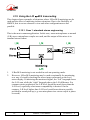
3.12.1. Case 1: standard stereo engineering
This is the most common application. In this case, mono microphones or normal
(L/R) stereo microphone couples are used, and the output of the mixer is in
standard stereo format.
1.
L/RM/S matrixing is not needed in such an operating mode.
2.
However, L/RM/S matrixing may be used occasionally for monitoring,
as a way of visually checking the stereo image coherence on the level
meter display. If matrixing the monitored signal, the “left” bargraph shows
the L+R sum, while the “right” bargraph shows the L-R difference. For
common stereo production, the L-R level should be much lower than the
L+R level, especially when mono compatibility is desired. On the
contrary, L-R level higher than L+R level would warn about a possible
problem in sound pick-up (e.g. one microphone in a stereo couple is phase
reversed).
36
4MinX - User manual
55 000 061 - E
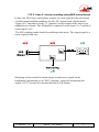
3.12.2. Case 2: stereo recording using M/S microphones
In this case, M/S stereo microphone couples are used (typically the association
of a directional cardioid transducer for the “M” channel and a bidirectional
“figure of 8” transducer for the “S” channel), but the output of the mixer is in
standard stereo format. The M should be connected on the input 1 or 3 and the S
on the input 2 or 4.
The M/S coupling mode should be enabling in the menu. The output signal is a
stereo signal in this case.
Matrixing is also needed for monitoring a normal stereo signal on the
headphones (monitoring set in “M/S” position), except for monitoring the
output “OUT” because it is already decoded to L/R format.
.
55 000 061 – E
4MinX - User manual
37
3.12.3. Case 3: M/S recording using M/S microphones
In this case, M/S stereo microphone couples are used, and the output is kept in
M/S format for recording. In this way, further stereo image processing is made
possible with studio equipment in later production.
The mixer buses process M (Mid) and S (Side) signals. L/RM/S matrixing is
not applied at the MAIN output (Outputs kept configured in “L/R” mode).
Monitoring is here set in “M/S” mode, as matrixing is needed for monitoring a
normal stereo signal on the headphones and meters.
38
4MinX - User manual
55 000 061 - E
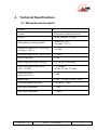
4. Technical Specifications
4.1. Microphone/Line inputs
Number
4
Format
Electronic symmetrical input
Socket
XLR3 Femelle, 3 points
Microphone powering modes
"Phantom", 48 V
"Tonader" T12 V
Maximum input level ( with "Pad"
on input 1 and 2)
+39 dBu
Maximum input level ( input 3 &4)
+19 dBu
Input headroom
40 dB
Input stage gain (menu setting)
0 to 50 dB, 10 dB steps
Equivalent input noise (EIN)
(Gin = 50 dB)
< -128 dBu
(200 , 22 Hz - 22 kHz)
Maximum gain,
analog in to out
90 dB
Bandwidth
10 Hz - 50 kHz (+0 dB, -1 dB)
Common Mode Rejection
90 dB @ 1 kHz
Mic Input impedance
> 2 k
Line Input impedance
> 10k
55 000 061 – E
4MinX - User manual
39
4.2. Line input
Number
1 x 2 channels
Format
2 channels, electronically
Female 5-pin XLR
1 : Ground
2 : Line 1 +
3 : Line 1 –
4 : Line 2 +
5 : Line 2-
Socket
Maximum input level
+24 dBu
Bandwith
10 Hz - 50 kHz (+0 dB, -1 dB)
Commun mode rejection
90 dB @ 1 kHz
Input Impedance
> 10k
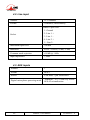
4.3. AES inputs
Number
3
Format
AES-3
Socket
XLR male 3-pin Switchcraft
Digital microphone powering mode
"Phantom", 10 V 250mA by socket
AES-42 normalization
40
4MinX - User manual
55 000 061 - E
4.4. "Line Out" balanced analog outputs
Number
2
Format
2 channels, electronically
Socket
Male 5-pin XLR
1 : ground
2 : Line 1/3 +
3 : Line 1/3 –
4 : Line 2/4 +
5 : Line 2/4-
Output attenuators (Pad)
-40 dB, balanced, separate for L and R
Maximum output level
(= 0 dBFS)
Adjustable via menu,
-9 dBu to +22 dBu
Source impedance
100
Output balance
40 dB, 20Hz - 20 kHz
Accuracy
> 60 dB, 20Hz - 20 kHz
Channel isolation
> 90 dB (22Hz - 22 kHz)
Signal/Noise Ratio
> 80 dB (soit THD+N < 0,01 %)
SINAD
(Signal to Noise and Distortion Ratio)
40 dB, 20Hz - 20 kHz
55 000 061 – E
4MinX - User manual
41
4.5. "Line Out" unbalanced analog outputs
Audio signals are the same as line output 1 and 2.
Format
2 channels, unbalanced
Socket
Mini-jack 3.5mm, stereo
Output level
6dB below balanced output
Maximum output level
+16 dBu
Source impedance
100
4.6. Digial outputs
3 mini XLR TA3 provide 2 digital channels 3 times.
The pin allocation of the “TA3” socket is as follows:
Pin
Function
1
Ground
2
+ Output
3
- Output
The outputs levels have an AES level, 4Vc-c110 .
The SPDIF adaptor cable (See Annex: Accessory), make audio level adaptation
to have these characteristic:
42
4MinX - User manual
55 000 061 - E
Protocol
CEI 958 , SPDIF, "consumer"
Format
Unbalanced, Transformer isolated
Connector
RCA mal
Level ( on 75 )
0,5V c-c
Source Impedance
75
4.7. Headphone output
Socket
Jack 6.35mm, stereo
Maximum output level
+20 dBu
Acceptable output load
16
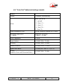
4.8. "Direct I/O" interface
55 000 061 – E
4MinX - User manual
43
Pinout of the subD 9 pins:
Pin
Function
1
Pre microphone amplifier channel 1
2
Pre microphone amplifier channel 3
3
Ground
4
Contact
5
power (+2,5v)
6
Pre microphone amplifier channel 2
7
Pre microphone amplifier channel 4
8
Ground
9
Command input (0V..+2.5V)
44
4MinX - User manual
55 000 061 - E
4.9. "EXT I/O": Interface for RF transmitters/receivers
Socket
12-pin, Neutrik MiniCon
Audio signals for transmitters
Unbalanced, 2 channels, line level
Maximum level
Adjustable via menu, -20 dBu to +10 dBu
Source impedance
1 k
The pin allocation of the “EXT I/O” socket is as follows:
Pin
Function
Direction
1
L signal to RF transmitter
Output
2
Not used
-
3
Analog signal ground
-
4
Analog signal ground
-
5
R signal to RF transmitter
Output
6
+ Input 4bis
Input
7
- Input 4bis
Input
8
+9V output
Output
9
- Input 3bis
Input
10
Analog signal ground
-
11
+ Input 3bis
Input
12
-
Input
55 000 061 – E
4MinX - User manual
45
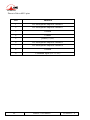
4.10. Power supply
Socket
Hirose HR10-7R-4S female 4 pins
Nominal Voltage
12 V
Minimum Voltage
8 V to supply 4MinX and 10V minimum
for the battery charger
Maximum Voltage
18 V
The power socket has following pin allocation:
Pin
Function
1
Ground
2
3
+ External DC for the internal battery charger
4
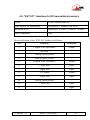
+ 4Minx external DC input
4.1. Time Code
Pin
Function
1
Ground
2
-LTC
Input
3
ASCII
Input/output
4
Tuning
Output
5
LTC
Output
46
4MinX - User manual
Direction
55 000 061 - E
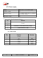
4.2. Dimensions and weight
Dimensions
(including connectors)
260 x 75 x 195 mm
(10.2”x3.0”x7.7”)
1900 g
Weight
4.3. Environmental
4MINX can operate from–20 °C to +55 °C ambient temperature (-4 °F to
131 °F).
4MINX complies with EC directives regarding safety, EMC and hazardous
substances (RoHS):
55 000 061 – E
Safety : compliant with EN60950
Susceptibility: compliant with EN50082-1
Emission: compliant with EN55022 (class B)
4MinX - User manual
47
4.4. Options
4.4.1. : XLR3 or Hirose 10 pins
On request 4MinX can be equipped with XLR3M in place of XLR5M outputs.
In this case, only two channels will be available instead of the 4 channels.
Upon request, replacing the female base XLR5M outputs 3/4, 4MinX can be
equipped with a base 10 pins Hirose RM15TRD-10S, for wire connection for
"Go /Return", unbalanced, with a two channels analog recorder. The entrance is
style accessible on the XLR 5F.
1
Left output +
5
Right input +
2
Left output -
6
Right input -
3
Right output +
7
Left input +
4
Right output -
8
Left input -
9
Ground
10
Ground
48
4MinX - User manual
55 000 061 - E
5. Annexes
5.1. Overview of connectors and front panel elements
4MinX’s front panel :
1
2
Channel change setting keys
Channel gain
9
Monitoring menu access
3
Panpot or other feature
10
Display
4
Channel adjustment & status
11
“ On/Off – Escape key and OK
key
5
Master gain & bus level L/R
12
Rotary interface
6
7
External DC/Charge” LED
Function keys
13
14
Headphone volume control
Slate microphone
8
Recording keypad
15
Shift key
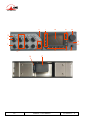
4Minx’s back panel :
1
Battery socket
2
NP-F Battery
55 000 061 – E
4MinX - User manual
49
7
6
10
11
12
1
2
14
15
3
5
4
16
50
8
9
13
17
4MinX - User manual
55 000 061 - E
Left Panel:
1
Mic/Ligne inputs ( XLR3F)
2
Digital inputs AES-3 / 42 (XLR3F)
3
Minicon 12pins interface for wireless transmitter/receiver
4
Digital outputs AES-3 ( TA3)
Right panel:
5
6
7
8
9
10
11
12
13
14
15
16
55 000 061 – E
Stereo headphone output
Auxiliary stereo output, unbalanced
Main “Line” outputs, balanced
Line In / Return inputs
Direct outputs from the 4 channel
External power input
Ethernet interface
SD/SDHC-CARD holster
USB host
Micro USB 2.0 OTG
Time Code input/output ( Optionel )
Word clock input ( Optionel)
4MinX - User manual
51
1
3
2
4
6
9
8
7
5
16 14 13
12
11
15
10
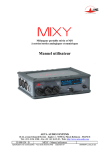
5.2. Block diagram
52
4MinX - User manual
55 000 061 - E
55 000 061 – E
4MinX - User manual
AES 3 & 4
AES 1 & 2
AES42
( Ph 10V )
Outpre1
Outpre2
Outpre3
Ovl
AES Pre 3&4
-90...+36dB
-90...+36dB
-90...0dB
Balance
or S width
+14
+4
+4
AES Pre 1&2
Out Pre1
Out Pre2
Out Pre3
Out Pre4
Limiter
Balance
or S width
+14
+4
+4
Outpre4
Line Pre 1&2
-100 to
+20dB
Ovl
Ovl
-100 to
+20dB
Ovl
Synchro
Sam ple
rat e
conve rter
Sam ple
rat e
conve rter
-6...+24dB
(1dB steps)
AES42
( Ph 10V )
PAD
12dB
P48
T12
Off
Ext 4
PAD
20dB
PAD
20dB
0...50dB
HPF
(10dB steps) -/50Hz
Coupling
Stereo / MS
Line1&2
Input 4
Ext I/O
Ext 3
P48
T12
Off
P48
T12
Off
P48
T12
Off
Mic
power
Coupling
Stereo / MS
Input 3
Input 2
Input 1
Line Post 1&2
P hase
SubD 9pts
53
Tone
generator
Slate
1000&400Hz
AES Post 3&4
A ES Post 1&2
Pre 4
HPF
50Hz to
300Hz
Pre 3
Pre 2
HPF
50Hz to
300Hz
Pre 1
L/R/C
L/R/C
L/R/C
Post 4
L/R/C
M/S
L/R/C
PanPot
P ost 3
Post 2
L/R/C
M/S
L/R/C
PanPot
Post 1
Tone
Slate
www.aeta-audio.com
L R L R
Master
Pre 1
Mixdown
(BUS)
Bus L
Bus R
Aux R
Auxiliary
( AUX )
Aux L
AES Post 3&4
AES Post 1&2
Line Post 1&2
Post 4
Post 3
Post 2
Post 1
AES Pre 3&4
AES Pre 1&2
Line Pre 1&2
Pre 4
Pre 3
Pre 2
Level
metering
L/R, L+R,..
MS,M+S,...
Double M/S
Format A
Format B
Routing
Play1 to 8
Up to 8 sources
Bargraph
Ext I/O
SD
I/O 2
I/O 1
Line out 3&4
3.5mm
Line out 1&2
Recorder
6.35mm
AES 5&6
AES 3&4
AES 1&2
PAD
-40dB
PAD
-40dB
5.3. Level maps
54
4MinX - User manual
55 000 061 - E
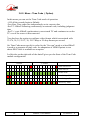
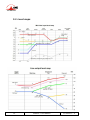
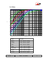
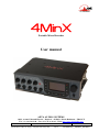
5.4. Filters
-0
-2
-4
-6
-8
-1 0
-1 2
-1 4
-1 6
-1 8
d
B
-2 0
r
-2 2
-2 4
-2 6
-2 8
-3 0
-3 2
-3 4
-3 6
-3 8
-4 0
20
30
40
50
60
70
80 90
200
300
400
500
Hz
Blue
No filter
Black
50Hz 18dB/Oct Analog
Green
50Hz 12dB/Oct Digital
Red
80Hz 12dB/Oct Digital
Pink
120Hz 12dB/Oct Digital
Dark blue
160Hz 12dB/Oct Digital
Cyan
200Hz 12dB/Oct Digital
Green
300Hz 6dB/Oct Digital
55 000 061 – E
4MinX - User manual
55
600 700
1k
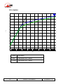
5.5. Limitor
+2
-0
-2
-4
-6
-8
d
-1 0
B
r
-1 2
-1 4
-1 6
-1 8
-2 0
-2 2
-2 4
-4 0
-3 5
-3 0
-2 5
-2 0
-1 5
-1 0
-5
+0
+5
+ 10
dB u
56
Black
No limitor
Blue
Threshold set to -6dBFs
Green
Threshold set to -8dBFs
4MinX - User manual
55 000 061 - E
+ 15
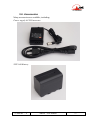
5.6. Accessories
Many accessories are available, including:
Power supply AC/DCconvertor
NPF-960 Battery
55 000 061 – E
4MinX - User manual
57
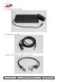
NP1 holdster for NP1 battery
Car adaptor power cable
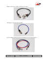
Adaptor cable XLR5 to 2 XLR3 for line outputs
58
4MinX - User manual
55 000 061 - E
Adaptor cable from 2 XLR3 to XLR5 for line inputs
AES adaptor cable from TA3 to XLR3
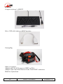
Specific adaptor cable for wireless microphone receiver and transmitter
55 000 061 – E
4MinX - User manual
59
Compact keyboard : QZERTY
Micro USB cable adptor to HOST interface
Carring Bag
Other (on request):
Adaptor cable for AES output to SPDIF on RCA
Adaptor Time code cable between Lemo 5 and 2 BNC connectors
MiniCon 12pins alone
60
4MinX - User manual
55 000 061 - E
NOTE
____________________________________________________________
____________________________________________________________
____________________________________________________________
____________________________________________________________
____________________________________________________________
____________________________________________________________
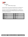
____________________________________________________________
___________________________________________________________
____________________________________________________________
____________________________________________________________
____________________________________________________________
____________________________________________________________
____________________________________________________________
____________________________________________________________
55 000 061 – E
4MinX - User manual
61
©2012 AETA AUDIO SYSTEMS www.aeta-audio.com