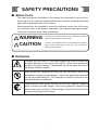
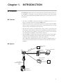
1
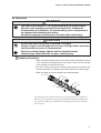
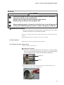
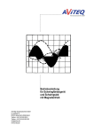
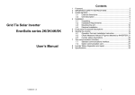
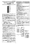
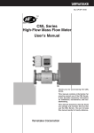
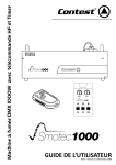
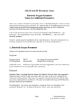
No. CP-SP-1190E
TM
MVF Series
Micro Flow Vortex Gas Flowmeter
User's Manual
Thank you for purchasing an MVF Series
flowmeter.
This manual contains information for
ensuring the correct use of the MVF
Series flowmeter. It also provides necessary information for installation,
maintenance, and troubleshooting.
This manual should be read by those
who design and maintain equipment
that uses the MVF Series flowmeter. Be
sure to keep this manual nearby for
handy reference.
RESTRICTIONS ON USE
This product has been designed, developed and manufactured for general-purpose
application in machinery and equipment.
Accordingly, when used in applications outlined below, special care should be taken to
implement a fail-safe and/or redundant design concept as well as a periodic
maintenance program.
• Safety devices for plant worker protection
• Start/stop control devices for transportation and material handling machines
• Aeronautical/aerospace machines
• Control devices for nuclear reactors
Never use this product in applications where human safety may be put at risk.
NOTICE
Be sure that the user receives this manual before the product is used.
Copying or duplicating this user’s manual in part or in whole is forbidden. The information and specifications in this manual are subject to
change without notice.
Considerable effort has been made to ensure that this manual is free
from inaccuracies and omissions. If you should find an error or omission, please contact Yamatake Corporation.
In no event is Yamatake Corporation liable to anyone for any indirect,
special or consequential damages as a result of using this product.
©2005 Yamatake Corporation ALL RIGHTS RESERVED
TM
TM
µF and Micro Flow are trademarks of Yamatake Corporation in Japan.
SAFETY PRECAUTIONS
■ About Icons
The safety precautions described in this manual are indicated by various icons.
Please be sure you read and understand the icons and their meanings described
below before reading the rest of the manual.
Safety precautions are intended to ensure the safe and correct use of this product, to prevent injury to the operator and others, and to prevent damage to property. Be sure to observe these safety precautions.
WARNING
CAUTION
Warnings are indicated when mishandling this product
might result in death or serious injury.
Cautions are indicated when mishandling this product
might result in minor injury to the user, or only physical
damage to the product.
■ Examples
Triangles warn the user of a possible danger that may be caused by
wrongful operation or misuse of this product. These icons graphically
represent the actual danger. (The example on the left warns the user of
the danger of electric shock.)
White circles with a diagonal bar notify the user that specific actions are
prohibited to prevent possible danger. These icons graphically represent
the actual prohibited action. (The example on the left notifies the user
that disassembly is prohibited.)
Filled-in black circles instruct the user to carry out a specific obligatory
action to prevent possible danger. These icons graphically represent the
actual action to be carried out. (The example on the left instructs the user
to remove the plug from the outlet.)
i
WARNING
If this device is used with flammable gases such as natural gas,
propane or butane, mount it on the upstream side of the safety shutoff
valve.
When air gets in the pipe and an explosive mixture is produced, and if a
sensor should make a spark due to lightning or other reasons, the mixture may explode inside the pipe.
The mass of this device is 7 to 23kg according to the model number.
Ensure to take complete precautions and care while handling for transportation or installation. For safe handling, two or more persons are
required while handling this device.
Accidental dropping of the device on the foot might cause injury.
Do not hold the device by the converter alone. Doing so might damage
the device, or the pipe connector section may drop off.
Do not use this device or its installed pipes as a scaffolding.
Doing so might damage the device or the pipe, or might cause physical
injury.
Do not disassemble this device.
If it is disassembled when pressure remains in the pipes, the device
could be damaged or someone could be injured by flying parts.
CAUTION
Be sure that the operating gas temperature does not fall below -15°C.
Using the gas below -15°C, the O-ring might crack and cause gas leakage.
Prevent foreign matter from entering the device.
If the rust, water droplet, oil mist or dust in the piping flows into the
device, measurement error might occur and result in damaging the
device.
If there is a possibility that any foreign matter flows into the device,
provide a filter, strainer or mist trap capable of eliminating more than
1µm foreign matter at the upstream, and periodically inspect and
replace the filter.
If this device is used for monitoring flowrate of the burner, consider the
piping instrumentation lest the backfire damage this device.
When connecting the load to the output terminals, do not exceed the
rated value shown in the specifications.
Doing so might cause the damage of this device.
ii
CAUTION
This device is a precision instrument. Do not drop it or subject it to
shock. Doing so might damage the device.
When connecting flanges, tighten with the specified torque.
Otherwise gas could leak from the pipe, causing injury.
When mounting the device, firmly fasten to prevent vibration.
Do not peel off the pipe connector port seals until immediately before
you connect the piping. Doing so might allow foreign objects to enter
the connector port and cause defective operation.
Do not flush when the device is mounted in the pipe.
Doing so might cause damage due to entry of foreign matter and cause
faulty operation or errors in measurement.
Before wiring, be sure to turn the power OFF.
Before supplying power, be sure to check that there is no wiring error. A
wiring error might damage the device or cause a dangerous condition.
Do not use this device outside of the operating pressure range. Also,
do not subject this device to a pressure above the pressure resistance.
Doing so might damage this device.
iii
Organization of This User's Manual
This manual is organized as follows:
Chapter 1. INTRODUCTION
This chapter describes features on this device.
Chapter 2. NAMES AND FUNCTIONS OF PARTS
This chapter describes the NAMES AND FUNCTIONS OF PARTS on this device.
Chapter 3. INSTALLATION, MOUNTING, WIRING
This chapter describes installation, mounting and wiring on this device.
Chapter 4. TROUBLESHOOTING
This chapter describes how to investigate and remedy trouble that may occur during operation of this device.
Chapter 5. SPECIFICATIONS
This chapter describes the specifications and external dimensions of this device.
Conventions Used in This Manual
The following conventions are used in this manual:
Handling Precautions:
Handling Precautions indicate items that the user should pay attention to
when handling the MVF Series.
Note:
:
Notes indicate information that might benefit the user.
This indicates the item or page that the user is requested to refer to.
(1), (2), (3):
Numbers within parentheses indicate steps in a sequence or parts of an
explanation.
AL01:
1000.0
This indicates 7-segment indication on the display.
iv
Contents
SAFETY PRECAUTIONS
Organization of This User's Manual
Conventions Used in This Manual
Chapter 1.
INTRODUCTION
■
■
■
■
Chapter 2.
Introduction • • • • • • • • • • • • • • • • • • • • • • • • • • • • • • • • • • • • • • • • • • • • • • • • • • • • • • • • • • • • • 1
Features • • • • • • • • • • • • • • • • • • • • • • • • • • • • • • • • • • • • • • • • • • • • • • • • • • • • • • • • • • • • • • • • • 1
System • • • • • • • • • • • • • • • • • • • • • • • • • • • • • • • • • • • • • • • • • • • • • • • • • • • • • • • • • • • • • • • • • • 1
Model selection table • • • • • • • • • • • • • • • • • • • • • • • • • • • • • • • • • • • • • • • • • • • • • • • • • • • • 2
NAMES AND FUNCTIONS OF PARTS
■ Body • • • • • • • • • • • • • • • • • • • • • • • • • • • • • • • • • • • • • • • • • • • • • • • • • • • • • • • • • • • • • • • • • • • • • 3
■ Display • • • • • • • • • • • • • • • • • • • • • • • • • • • • • • • • • • • • • • • • • • • • • • • • • • • • • • • • • • • • • • • • • • 4
Chapter 3.
INSTALLATION, MOUNTING, WIRING
■
■
■
■
Chapter 4.
Installation • • • • • • • • • • • • • • • • • • • • • • • • • • • • • • • • • • • • • • • • • • • • • • • • • • • • • • • • • • • • • • 6
Precautions for piping installation • • • • • • • • • • • • • • • • • • • • • • • • • • • • • • • • • • • • • • 6
Piping work • • • • • • • • • • • • • • • • • • • • • • • • • • • • • • • • • • • • • • • • • • • • • • • • • • • • • • • • • • • • • • 9
Wiring • • • • • • • • • • • • • • • • • • • • • • • • • • • • • • • • • • • • • • • • • • • • • • • • • • • • • • • • • • • • • • • • • • 11
TROUBLESHOOTING
■ Nothing on display • • • • • • • • • • • • • • • • • • • • • • • • • • • • • • • • • • • • • • • • • • • • • • • • • • • • • 15
■ Error message (faulty operation) • • • • • • • • • • • • • • • • • • • • • • • • • • • • • • • • • • • • • • • 15
■ Alarm display • • • • • • • • • • • • • • • • • • • • • • • • • • • • • • • • • • • • • • • • • • • • • • • • • • • • • • • • • • 16
Chapter 5.
SPECIFICATIONS
■
■
■
■
Specifications • • • • • • • • • • • • • • • • • • • • • • • • • • • • • • • • • • • • • • • • • • • • • • • • • • • • • • • • • • 17
Specifying accuracy • • • • • • • • • • • • • • • • • • • • • • • • • • • • • • • • • • • • • • • • • • • • • • • • • • • 18
Tables for specifying volumetric flow rate accuracy (in air) • • • • • • • • • • • • 21
Tables for accuracy after temperature and pressure • • • • • • • • • • • • • • • • • • • 22
compensation (in air)
■ Pressure loss • • • • • • • • • • • • • • • • • • • • • • • • • • • • • • • • • • • • • • • • • • • • • • • • • • • • • • • • • • 24
■ External dimensions • • • • • • • • • • • • • • • • • • • • • • • • • • • • • • • • • • • • • • • • • • • • • • • • • • • 25
v
Chapter 1.
INTRODUCTION
■ Introduction
The MVF Series Micro Flow Vortex Gas Flowmeter (hereafter called "the device"
or "the MVF") is a thermal vortex gas flowmeter featuring a wide measurement
range. It uses the Yamatake-designed Micro Flow sensor (or "µF sensor") as a vortex generator.
■ Features
• 35% more of the MVF's component materials are available for re-use or recycling, as compared with the conventional CMK model.
• Temperature and pressure compensation functions are integrated into the MVF.
Since expensive temperature and pressure compensation devices are not
required, a large cost reduction can be expected.
• This device incorporates a µF (Micro Flow) sensor a mere 1.7mm square and
0.5mm thick, made possible by silicon micro-machining and thin-film technologies. By using this high-sensitivity, high-speed sensor to detect vortex frequency, measurement rangeability of 100:1 has been achieved.
• The entire MVF is provided with wide range of functions to meet various applications needs: LCD display function, analog output (4 to 20mA), integrating
calculation, display and integral pulse output (open collector).
Also, an RS-485 communications function is provided as a standard feature, so
a large amount of instrumentation cost reduction can be achieved when data is
uploaded.
■ System
Pulse counter
PCG13
put
MVF
e
uls
out
Personal computer etc.
P
CMC10L
LOADER
RS-232C
power
SD
RD
HOST CMC
CMC ADDRESS
Communications (RS-485)
HOST CMC
B.RATE
RD
CMC LOCAL
SD
11
12
13
14
ERR
15
RESET
CMC10
Smart terminal
EST-Z series
PLC
4 to 20mA
instantaneous flow rate
output
Controller
SDC series etc.
1
Chapter 1. INTRODUCTION
■ Model selection table
The following shows the model Nos. for this flowmeter:
Basic
model No.
Pipe
size
Model Material Connecti- Gas
type
on method type
Output Power Commu- Flow and moun- Option 1 Option 2 Appended
nication ting direction
MVF
Descripton
Micro Flow Vortex Flowmeter
Pipe size 50A (2B)
Pipe size 80A (3B)
Pipe size 100A (4B)
Pipe size 150A (6B)
With temperature/pressure compensation
function
Without pressure compensation but with
temperature compensation
Material SUS304
JIS/ANSI wafer
Air, Nitrogen, Algon
Oxygen (Be sure to specify code "1" in the
opiton 1 gas-contacting parts treated to be oil
free) *1
Carbondioxide
Natural gas (LNG base), Methane
Propane
Butane
4 to 20mAdc output + Integration pulse output
Power 24Vdc
RS-485 Communication (EST, WEB100,
CMC10G communication)
Horizontal (Flow direction:left to right)
Converter on top *2
Horizodntal (Flow direction:left to right)
Converter on bottom *2
Horizontal (Flow direction:right to left)
Converter on top *2
Horizontal (Flow direction:right to left)
Converter on bottom *2
Vertical (Flow direction:down to up)
Converter on left *2
Vertical (Flow direction:up to down)
Converter on left *2
Option 1 none
Gas-contacting parts treated to be oil free
(Necessary if gas type is oxygen) *1
Option 2 none
Product version
050
080
100
150
0
L
S
U
N
S
C
G
P
B
0
1
1
0
1
2
3
4
5
0
1
0
0
*1: If the gas type is oxygen, be sure to specify oil free treatment.
*2: Flow and mounting directions
Flow direction: Horizontal (left to right)
Converter on top
Converter on bottom
Flow direction: Horizontal (right to left)
Converter on top
Converter on bottom
Flow
direction
Flow
direction
Flow
direction
Flow
direction
Code: 0
Code: 1
Flow direction: Vertical (down to up)
Converter on left
Code: 3
Code: 2
Flow direction: Vertical (up to down)
Converter on left
Flow
direction
Flow
direction
Code: 4
2
Code: 5
Chapter 2.
NAMES AND FUNCTIONS OF PARTS
■ Body
Converter
Label
Terminal housing cover
Wiring connection port
Display
Terminal block
Gauge pressure sensor
A-A cross-section of flow passage
A
A
Flow direction
µF sensor
µF sensor
Pipe connector (wafer)
Vortex generator
Display
Used for the display of instantaneous flow rate, integrated flow rate, and
alarm status and error of this device. For details of the display, refer to;
■ Display (on next page).
Label
Indicates model number, range, and pulse rate. Check that they are the
same as the specifications ordered.
Converter
Calculates temperature, pressure, etc.
Wiring connection port
There are 2 wiring connection ports. Used for connecting an electric wiring
conduit and mounting the included waterproof gland.
Terminal block
Used for wiring a power supply to the device, for 4-20mAdc output, integrated pulse output and communications.
Gauge pressure sensor
Detects pressure.
µF Sensor
Detects vortex frequency and temperature.
Pipe connector
Wafer connection. Pipes are connected by sandwiching the pipe connector
between flanges.
Vortex generator
Generates vortex.
3
Chapter 2. NAMES AND FUNCTIONS OF PARTS
■ Display
CAUTION
Before pressing the reset switch, touch a metal surface such as the housing
of the device to discharge static electricity.
Reset switch
3
m/min
3
m/h
OVER setting
7-segment display upper
SCFM kg/h
CF
m3
kg
7-segment display lower
1
2
3
4
5
6
7
8
B D
A
O
N
4
8
7 9
Loader jack
56
23
F01
E
C
Station address setting switch
Communications parameters switch
Reset switch
This switch resets the integrated (cumulative) value. When this reset switch
is pressed for 3 seconds, the integrated value is reset to 0.
Upper 7-segment display
Displays instantaneous flow rate.
(Example: 10000.0 m3/h)
Lower 7-segment display
Displays integrated flow rate.
(Example: MVF050 1000000.0 m3
MVF080/100/150 10000000 m3)
Station address setting switch
This switch sets the station address for the device.
For setup details, refer to;
MVF Series Communications Functions (CP-SP-1183E).
Communications parameters switch
This switch sets the communications parameters for the device.
For setup details, refer to;
MVF Series Communications Functions (CP-SP-1183E).
Loader jack
The loader jack is used by the manufacturer when servicing the device.
Please do not try to use it.
4
Chapter 3.
INSTALLATION, MOUNTING, WIRING
WARNING
If this device is used with flammable gases such as natural gas,
propane or butane, mount it on the upstream side of the safety shutoff
valve.
When air gets in the pipe and an explosive mixture is produced, and if a
sensor should make a spark due to lightning or other reasons, the
mixture may explode inside the pipe.
The mass of this device is 7 to 23kg according to the model number.
Ensure to take complete precautions and care while handling for
transportation or installation. For safe handling, two or more persons
are required while handling this device.
Accidental dropping of the device on the foot might cause injury.
Do not hold the device by the converter alone. Doing so might damage
the device, or the pipe connector section may drop off.
Do not use this device or its installed pipes as a scaffolding.
Doing so might damage the device or the pipe, or might cause physical
injury.
Do not disassemble this device.
If it is disassembled when pressure remains in the pipes, the device
could be damaged or someone could be injured by flying parts.
CAUTION
Prevent foreign matter from entering the device.
If the rust, water droplet, oil mist or dust in the piping flows into the
device, measurement error might occur and result in damaging the
device.
If there is a possibility that any foreign matter flows into the device,
provide a filter, strainer or mist trap capable of eliminating more than
1µm foreign matter at the upstream, and periodically inspect and
replace the filter.
This device is a precision instrument. Do not drop it nor subject it to
shock. Doing so might damage the device.
When mounting the device, firmly fasten to prevent vibration.
Handling Precautions
• When connecting to the pipe, be sure to check that there is no inclination
of pipes nor any pipe center line misalignment, and then install the
device. Doing so might cause leakage.
• When mounting the device, firmly fasten to prevent vibration.
• The communication line must be separated from power lines, and do not
lay in the same conduit.
Doing so might cause faulty operation.
5
Chapter 3. INSTALLATION, MOUNTING, WIRING
■ Installation
Avoid mounting this device in the following locations:
• Locations whose ambient temperature falls below -15˚C and rises above +60˚C
• Locations whose ambient humidity exceeds 90%RH
• Locations subject to sudden changes in temperature and condensation
• Locations be filled with corrosive gases and flammable gases
• Locations where there are lots of conductive substances (e.g. dust, salt or iron
dust), or organic solvents
• Locations subject to vibration or shock
• Locations subject to splashing by fluids (e.g. oil, chemicals.)
• Locations where strong magnetic or electrical fields are generated
Handling Precautions
• Although this device can be installed outdoors, if it is installed at the locations subject to direct sunlight, be sure to provide a sunshade.
Doing so might cause faulty operation.
■ Precautions for piping installation
• When this device is installed, be sure to provide the bypass piping as shown
below.
Also, for the valves before and after this device, use a ball valve like as having
the structure which does not disturb the gas flow.
Bypass piping valve
Upstream side
valve
6
MVF
Downstream side
valve
Chapter 3. INSTALLATION, MOUNTING, WIRING
• Provide a straight pipe section in upstream side and downstream side of the
installation location.
Refer to the drawings below for the length of upstream pipe section. D indicates
the connecting port size. Secure the length of more than 5D for the downstream
pipe section.
Type of Installation
Reducing pipe
Flow direction
10D min.
5D min.
Enlarging pipe
Flow direction
10D min.
5D min.
Pipe with 90° bend
Flow direction
10D min.
5D min.
Pipe with single-plane
double 90° bend
Flow direction
5D min.
10D min.
Pipe with threedimensional double
90° bend
Flow direction
20D min.
5D min.
• If the oil, water or dust is contained in a fluid, install a device to remove them.
If the oil, water or dust is contained in a fluid, they might cause measurement
error or faulty operation.
Note
• Remove the water using a dryer so that it does not cause dew condensation in
the pipe.
• Use a dust-eliminating filter of less than 1µm mesh.
• Use an oil-eliminating mist separator with the eliminating capability of residual oil density less than 0.01mg/m3.
7
Chapter 3. INSTALLATION, MOUNTING, WIRING
• Do not install at a location receiving the influence of pulsating flow.
Handling Precautions
• Do not install this device at the location near the exit of compressor. At
the location near the exit of compressor the strong pulsating flow is
caused and there might be a dispersing of iron powder depending on
the compressor type, there is a possibility of causing faulty operation.
Compressor
(screw type, etc.)
Compressor
MVF
Filter
Dryer Receiver MVF
tank
As shown in the above figure, provide the devices eliminating the foreign matters such as oil, water and iron powder, and install a receiver
tank as the measures against pulsating flow ; at the upstream of MVF
series.
• Take effective countermeasures in case of installation near a pump or
roots blower. If this device is installed near a pump or roots blower, it
may be affected by a pulsating flow. Install a volume tank or pulsationdamping device (muffler) between the pump or roots blower and this
device to suppress the influence of pulsation as much as possible.
• If the device is installed downstream of branched piping, it may detect
reverse flow rate. Be sure to take countermeasures as illustrated
below.
Example: In this application, Line A is operating but B is stopped.
Although the flow rate of B is essentially zero as detected
by the MVF in B, the MVF might count and integrate a false
flow rate caused by the influence of the flow in Line A.
Due to the influence of flow in Line A,
a false flow is detected in B.
Flow path
MVF
MVF
Line A operating
Line B stopped
Countermeasure 1
Install a valve on the upstream side of the MVFs if there is
an unused line, to eliminate the influence of flow in the
other line.
Valve
MVF
Valve
MVF
Line A
Line B
Countermeasure 2.
Design the system so that other devices do not receive the
output (4 to 20mA pulse) from the MVF on the unused line.
8
Chapter 3. INSTALLATION, MOUNTING, WIRING
■ Piping work
WARNING
The mass of this device is 7 to 23kg according to the model number.
Ensure to take complete precautions and care while handling for
transportation or installation. For safe handling, two or more persons
are required while handling this device.
Accidental dropping of the device on the foot might cause injury.
CAUTION
Do not flush when the device is mounted in the pipe.
Doing so might cause damage due to entry of foreign matter and cause
faulty operation or errors in measurement.
When connecting flanges, tighten with the specified torque.
Otherwise gas could leak from the pipe, causing injury.
Handling Precautions
• When connecting to piping, be sure to check before installation that there
is no inclination or displacement of the pipes. Failure to do so might
cause leakage or measurement error.
• Be sure to flush (cleaning the inside of pipe) before installation this
device to eliminate any foreign matter which might exist inside the pipe.
• When installing, pay special attention to the flow direction.
(Example: MVF100)
Flange
Gasket
Gasket
Flange
spacers
Flo
wd
ire
ctio
n
To mount this device, sandwich it between two pipe flanges (wafer mounting).
Note that spacers should be used to prevent displacement during mounting. The
use of spacers enables proper alignment of the piping and this device. Be sure to
use the spacers.
9
Chapter 3. INSTALLATION, MOUNTING, WIRING
● Flange shape
Use a flange which can secure a large contacting area with a gasket.
Good example
gasket
Bad example
Flange
Welded
portion
Welded
portion
(As the contacting area
with a gasket is small,
there is a fear of leakage.)
Pipe
● Flange connection
Tighten the flange with bolts.
Tightening torque differs by pipe size. Tighten at a torque that is within the range
specified in the table below.
Pipe size
Torque Unit : N • m(kgf • cm)
50A
80A
100A
150A
37 to 47 (378 to 480)
26 to 36 (265 to 367)
32 to 42 (327 to 429)
64 to 74 (653 to 755)
(The value in parentheses
indicates the reference value.)
Handling Precautions
• Tighten bolts so that they are uniformly tightened. If leakage does not
stop after tightening bolts, gradually tighten the bolts more a little at a
time.
• Tighten bolts within the specified tightening torque.
Otherwise, the bolts may be damaged.
• Do not forcibly insert into the narrow space between the flange faces.
Doing so might cause leakage or damage.
• Six of the 8 bolts on MVF080/100/150 models require the use of a
spacer to ensure that the are correctly aligned around the pipe
connection unit (wafer) and that they match up properly with the holes
in the pipe flanges.
● Diameter of gasket
A gasket is required for flange connection.
Refer to the table below for the inside diameter of gasket.
Pipe size
50A
80A
100A
150A
Inside diameter of gasket
(Reference value)
61mm
90mm
115mm
167mm
Handling Precautions
• If the inside diameter of the gasket is too small, it might disturb the flow
straightening condition inside of this device and cause inaccuracies.
• If the inside diameter is too large, it might cause leakage.
10
Chapter 3. INSTALLATION, MOUNTING, WIRING
■ Wiring
CAUTION
When connecting the load to the output terminals, do not exceed the
rated value shown in the specifications.
Doing to do so might cause the damage of this device.
Before wiring, be sure to turn the power OFF.
Before supplying power, be sure to check that there is no wiring error. A
wiring error might damage the device or cause a dangerous condition.
Handling Precautions
• Be sure to separate the communications wires from power lines, which
should not be laid in the same electrical conduit.
There are two wiring methods, direct cable lead-out and use of an electrical wiring
conduit.
When installing the device outdoors, be sure to use a conduit.
● Tools required
Phillips-head screwdriver, adjustable wrench (spanner)
● Procedure for direct cable lead-out
(1) Select a wiring connection port.
Handling Precautions
• There are 2 wiring connection ports. One port has a red cap and the
other has a plug. Decide whether to use one port or 2 ports depending
on the number of cables or desired separation of signal wires.
Red cap
Plug
(2) Remove the red cap from the wiring connection port. When leading out the
wiring from two ports, remove the plug also.
11
Chapter 3. INSTALLATION, MOUNTING, WIRING
(3) Remove the terminal cover.
(4) Put the packing on the supplied waterproof gland.
(5) Pass the cable through the waterproof gland, and mount the waterproof gland
in the wiring connection port.
Handling Precautions
• Never remove the packing from the waterproof gland.
• Use a cable that is 6 to 12mm in diamater.
(6) Connect the wiring to the terminal block.
(7) Put the terminal cover back in place.
● Procedure for using an electrical wiring conduit
The wiring connection port thread is G1/2.
(1) Select a wiring connection port.
Handling Precautions
• There are 2 wiring connection ports. One port has a red cap and the
other has a plug. Decide whether to use one port or 2 ports depending
on the number of cables or desired separation of signal wires.
12
Chapter 3. INSTALLATION, MOUNTING, WIRING
(2) Remove the red cap from the wiring connection port.
(3) When leading out the wiring from two ports, remove the plug also.
(4) Remove the terminal cover.
(5) Connect an electrical wiring conduit.
(6) Pass the wiring through the electrical wiring conduit and then connect the
wiring to the terminal block.
(7) Put the terminal cover back in place.
● Wiring connection example
External wiring connection
Internal circuit +24V
8
24Vdc power supply
COM
Pulse output wiring example
9
I+
Load
4 to 20mA
10
(1) No-voltage input type
5
Input
Counter
P+
5
0V
6
Pulse output
COM
6
(2) Voltage input type
Pull-up resistor
DA
5
1
DC power supply
(30V max.)
Input
Counter
DB
RS-485 communications
(A terminating resistor is
not attached)
2
6
0V
SG
7
FG
11
Handling Precautions
• Connect COM of 4-20mA output directly from the terminal block.
• Do not use the COM power supply terminal (4-20mA) or the COM pluse
output terminal as a common power supply terminal for external devices.
• Be sure that the pulse output never exceeds the output rating of this
device. When driving a relay, use a relay with a built-in diode for coil
surge absorption. Failure to do so may cause faulty operation.
13
Chapter 3. INSTALLATION, MOUNTING, WIRING
● Terminal layout
DA
1
2
DB
7
3
8
5
6
11
Terminal
No.
1
2
3
4
5
6
7
8
9
10
11
Signal
name
DA
DB
Unused
Unused
P+
COM
SG
+24V
COM
I+
COM P+
10
I+
4
9
COM +24V SG
Wiring label
Description
RS-485 communication DA
RS-485 communication DB
Do not use
Do not use
Pulse output (NPN open collector)
Common
RS-485 communication common
24V power
Common
4 to 20mA output
Ground terminal
Handling Precautions
• Connect each terminal securely using crimp type terminal lugs to ensure
firm contact area.
• Use crimp type terminal lugs applicable to M4 screw.
• Be sure that the tightening torque of terminal screw is less than 0.8N•m.
• Use the JIS C 3401 cables for control (CVV etc.) of less than 2.2mm dia.
for the wiring except RS-485 communications.
• Use the twisted-pair shielded cables for the wiring of RS-485 communications. Be sure to apply terminating resistors (150Ω 1/2W).
For communications of wiring details, refer to;
MVF Series Communications Functions (CP-SP-1183E).
14
Chapter 4.
TROUBLESHOOTING
If there is a problem with this device, refer to the table below.
■ Nothing on display
Make sure that the correct power voltage being applied and the polarity are correct.
Make sure that the electric wires are connected.
■ Error message (faulty operation)
When an error message is displayed, contact Yamatake Corporation. Repair at a
Yamatake facility is required.
Error
message
Failure location
Cause
Er01
Flow sensor
Flow sensor error
Er02
Temperature sensor
The cause may be an error or burnout of the sensor for temperature
detection. Alternatively dust, moisture or oil from the fluid may have
adhered to the sensor.
Er03
Flow sensor
Temperature sensor
There may be an error or burnout of the flow sensor or temperature
sensor. Alternatively dust, moisture or oil from the fluid may have
adhered to the sensor.
Er04
Pressure sensor
The cause may be an error or burnout of the pressure compensating
sensor.
Er05
Flow sensor
Pressure sensor
The cause may be an error or burnout of the flow sensor or pressure
sensor. Alternatively dust, moisture or oil from the fluid may have
adhered to the sensor.
Er06
Temperature sensor
Pressure sensor
The cause may be an error or burnout of the temperature sensor or
pressure sensor. Alternatively dust, moisture or oil from the fluid may
have adhered to the sensor.
Er07
Flow sensor
Temperature sensor
Pressure sensor
The cause may be an error or burnout of the flow sensor, temperature
sensor, or pressure sensor. Alternatively dust, moisture or oil from the
fluid may have adhered to the sensor.
Er08
EEPROM
The cause may be an error in the nonvolatile memory used by the
internal microcomputer.
15
Chapter 4. TROUBLESHOOTING
■ Alarm display
If conditions exceed the device's specified range, an alarm message and the instantaneous value are alternately displayed. In order to use this device within an allowable range, change the conditions of the fluid.
Alarm
display
AL01
AL02
AL03
AL04
AL05
AL08
AL09
AL10
AL11
AL12
AL13
AL16
AL17
AL18
AL19
AL20
AL21
Cause
Flowrate upper limit alarm
Temperature lower limit alarm
Flowrate upper limit alarm+Temperature lower limit alarm
Temperature upper limit alarm
Flowrate upper limit alarm+Temperature upper limit alarm
Pressure upper limit alarm
Flowrate upper limit alarm+Pressure lower limit alarm
Temperature lower limit alarm+Pressure lower limit alarm
Flowrate upper limit alarm+Temperature lower limit alarm+Pressure
lower limit alarm
Temperature upper limit alarm+Pressure lower limit alarm
Flowrate upper limit alarm+Temperature upper limit alarm+Pressure
lower limit alarm
Pressure upper limit alarm
Flowrate upper limit alarm+Pressure upper limit alarm
Temperature lower limit alarm+Pressure upper limit alarm
Flowrate upper limit alarm+Temperature lower limit alarm+Pressure
upper limit alarm
Temperature upper limit alarm+Pressure upper limit alarm
Flowrate upper limit alarm+Temperature upper limit alarm+Pressure
upper limit alarm
Flowrate upper limit alarm:
Temperature lower limit alarm:
Temperature upper limit alarm:
Pressure lower limit alarm:
Pressure upper limit alarm:
16
Flowrate speed 45m/s or more.
-15˚C or lower.
60˚C or more.
-50kPa or lower.
1000kPa or more.
Chapter 5.
SPECIFICATIONS
■ Specifications
Item
Specifications
MVF050
MVF080
MVF100
MVF150
50A (2B)
80A (3B)
100A (4B)
150A (6B)
13 to 1280m3/h (normal) 29 to 2826m3/h (normal) 44 to 4352m3/h (normal) 94 to 9364m3/h (normal)
Pipe size
Flowrate measurement
range (@23°C for air)
(at a pressure of 0.5MPa) "Normal" refers to the volumetric flow rate (m3/h) after converting to 0°C, 101.325kPa.
Applicable gas
Air, Nitrogen, Argon, Oxygen *1, Carbon dioxide, natural gas (LNG base), Methane, Propane, Butane,
and other inert gases and mixed gases outside the explosion limit range.
Volumetric flow rate
2%RD at
2%RD at
2%RD at
2%RD at
accuracy (@23°C for air)
74m3/h (normal)
109m3/h (normal)
154m3/h (normal)
283m3/h (normal)
Differs according to operating pressure. For details, refer to;
Tables for specifying volumetric flow rate accuracy (page 20)
Accuracy after
When pressure is 0.5MPa When pressure is 0.5MPa When pressure is 0.5MPa When pressure is 0.5MPa
temperature and
±3.5%RD at
±3.5%RD at
±3.5%RD at
±3.5%RD at
pressure compensation 75m3/h (normal) or more 110m3/h (normal) or more 157m3/h (normal) or more 287m3/h (normal) or more
For conditions other than the above, refer to;
Tables for accuracy after temperature and pressure compensation (page 21).
Since a gauge pressure sensor is used, atmospheric pressure fluctuation is not included.
Minimum measurable
8m3/h (normal)
11m3/h (normal)
15m3/h (normal)
32m3/h (normal)
flow rate (at pressure
of 0.1MPa)
Operating temperature -15 to +60°C
range
Operating pressure range 0.0 to less than 1.0MPa
Pressure resistance
1.5MPa
Operating humidity range 10 to 90%RH (No condensation allowed)
Flow rate calculation/
100ms
output updating cycle
Rated power supply
24Vdc
Current consumption
100mA max.
Output signal (1 point)
Instantaneous flowrate output: 4 to 20mAdc(Allowable load resistance 600Ω max.)
Maximum Current value: 23.2mA
Integrated pulse
Open collector output Absolute maximum rating: 30Vdc, 20mA max.
output (1 point)
Pulse weight MVF050: 0.01, 0.1, 1, 10
MVF080/100/150: 0.1, 1, 10, 100
Pulse width Output intervals of 1s or more: 0.5s
Output intervals of less than 1s: duty ratio 50%
Communication
RS-485 interface, Transmission line : 3-wire system
function 1
Communication distance 300m max., Compatible with Yamatake's products (EST, CMC10G, WEB100)
Transmission speed 2400, 4800, 9600, 19200bps Integrated value, instantaneous, value/warning, and
setting can be recorded
Communication
Mini-plug jack for PC Smart Loader connection, used in servicing by the manufacturer.
function 2
Display Flowrate
Instantaneous flowrate display: LCD 6 digits
display
Integrated flowrate: LCD 8 digits
Instantaneous Display unit MVF050/80/100 : 1 * * * * * m3/h
Flowrate
MVF150 : 1 * * * * m3/h
Integrated
Display unit MVF050 : * * * * * * * * m3(displayed down to the first decimal place)
Flowrate
MVF080/100/150 : * * * * * * * * m3 (no decimal point)
00000000 after counting up to 99999999
(For details of setup, refer to
MVF Series Communications Functions (CP-SP-1183E)
Status display
setting: for servicing by manufacturer. OVER: exceeding the flow rate range
Gas contacting parts
Flow passage:SUS304 µF sensor:Silicon, Gold etc., O ring: Type 4D (Viton)
material
Convertor material
Aluminum alloy (ADC12)
Convertor coating
Acrylic resin corrosion resistant coating
Coating color: Light beige
Display glass parts
Tempered glass: Thickness 10mm
material
Mounting direction
(flow direction) Horizontal/Vertical mounting
Connection type
Wafer connection
Wiring connection port Connection port: 2 locations, Connection standard:G1/2 female thread
Accessories: 2 water-proof glands attached
Sealing
(JIS C 0920 and IEC 60529 Water-proof and dust-proof structure on the assumption of outdoor
installation)
Mass(kg)
7
8
10
23
*1: Use for oxygen is possible only for models with oil inhibiting treatment for the gas-contacting parts.
17
Chapter 5. SPECIFICATIONS
■ Specifying accuracy
See the tables for specifying accuracy on pages 20 and following. The accuracy
tables show the ranges when the gas is air. To convert to other application conditions, calculate as shown below.
The Reynolds number (Re) used below is calculated using the formula
Re = (V × D)/ν.
V: velocity (m/s)
D: typical length (internal diameter of the MVF body(m))
MVF050: 52.5mm, MVF080: 78mm, MVF100: 96.8mm, MVF150: 142mm
ν: kinetic viscosity of the fluid (m2/s), = µ/ρ
For instance, in the case of air (dry air) at 0°C and 101.3kPa,
Viscosity µ =17.24 × 10⁻⁶ Pa·s
Density ρ =1.293kg/m3
From these conditions, the kinetic viscosity ν =13.35 × 10⁻⁶ m2/s.
Or, in the case of air (dry air) at 23°C and 700kPa,
ν =1.883 × 10⁻⁶ m2/s
As a calculation example, we will use the following conditions:
Installed flowmeter: MVF080
Fluid: air (dry air)
Operating pressure: 700kPa
Fluid temperature: 23°C
Atmospheric pressure: 101.3kPa
We will calculate the following items:
1. Minimum measurable flow rate
2. Maximum measurable flow rate
3. Accuracy after temperature and pressure compensation (examples: for 100 and
150m3/h (normal))
1. Minimum measurable flow rate (volumetric flow rate (m3/h) and mass flow rate (m3/h (normal))
First, the minimum measurable flow speed is determined as the larger of 0.3m/s or
the velocity at Re 3500. The velocity at Re 3500 is calculated from the formula for
calculating Re:
V = Re × ν / D.
Here, if Re = 3500, ν = 1.883 × 10⁻⁶m2/s, and D = 78 × 10–3m,
V = 3500 × 1.883 × 10–6 / (78 × 10–3) = 0.08m/s.
Since a velocity of 0.08m/s at Re 3500 is less than 0.3m/s, the minimum measurable velocity is 0.3m/s.
Now, the minimum measurable volumetric flow rate can be calculated as
Qactual (m3/h) = S × V × 3600 = 5.2.
S: flow path cross-section of MVF080 (m2) = (78 × 10–3)2 × π/4
V: velocity (m/s) = 0.3
Therefore, volumetric flow rate can be measured down to 5.2m3/h.
Next, we can calculate the minimum mass flow rate Qnormal (m3/h (normal)) at
0°C and one atmospheric pressure, with temperature and pressure compensation.
18
Chapter 5. SPECIFICATIONS
Qnormal (m3/h(normal)) = 5.2 × ((273+0)/(273+23)) × ((101.3+700)/101.3) = 38
Amount of temperature
compensation
Amount of pressure
compensation
Therefore, mass flow rate can be measured starting from a minimum of 38m3/h
(normal).
2. Maximum measurable flow rate (volumetric flow rate (m3/h) and mass flow rate (m3/h (normal))
MVF flowmeters can measure velocity up to 30m/s.
The volumetric flow rate Qactual (m 3 /h) at velocity 30m/s is determined by
Qactual (m3/h) = S × V × 3600 = 516.
S: flow path cross-section of MVF080 (m2) = (78 × 10–3)2 × π/4
V: velocity (m/s) = 30
The volumetric flow rate can be measured up to 516m3/h.
Next, we can calculate the mass flow rate at 0°C and one atmospheric pressure,
with temperature and pressure compensation, by
Qnormal (m3/h(normal)) = 516 × ((273+0)/(273+23)) × ((101.3+700)/101.3) = 3765
Amount of temperature
compensation
Amount of pressure
compensation
Mass flow rate can be measured up to 3765m3/h (normal).
3. Accuracy after temperature and pressure compensation
As an example, we will calculate the accuracy after temperature and pressure compensation at 100m3/h and 150m3/h (normal), using the following formula:
Accuracy after
( volumetric flow (%RD)2 + temperature (%RD)2 + pressure (%RD)2)
rate accuracy
accuracy
accuracy
compensation (%RD) =
Temperature and pressure sensor accuracy is as follows:
Temperature measurement accuracy: ±2% RD (absolute temperature base)
Pressure accuracy (% RD) = pressure measurement accuracy / (fluid pressure
(MPa) + 0.1013(MPa))
In this case, the pressure measurement accuracy is 1%FS in the 0 to 1MPa range.
In order to calculate the volumetric flow rate accuracy, Re is first calculated from
the mass flow rate (m3/h, normal).
The steps of the calculation are: mass flow rate → volumetric flow rate → velocity → Re.
Mass flow rate → volumetric flow rate calculation
Qactual (m3/h) = 100 × ((273+23) / (273+0) × (101.3 / (101.3 + 700)) = 13.7
Volumetric flow rate → Velocity calculation
Velocity V(m/s) = Qactual(m3/h) / S / 3600 = 13.7 / ((78 × 10–3)2 × π /4 / 3600 = 0.8
S: flow path cross-section of MVF080 (m2) = (78 × 10–3)2 × π /4
Velocity → Re calculation
Re = (V × D)/ ν = 0.8 × 78 × 10–3 / 1.883 × 10–6 = 33139
V: velocity (m/s) = 0.8
D: internal diameter of the MVF body (m); for MVF080, D = 78mm
ν: kinetic viscosity of fluid (m2/s)
For dry air, 23°C and 700kPa, ν = 1.883 × 10⁻⁶m2/s
Volumetric flow rate accuracy is checked by the Re value.
19
Chapter 5. SPECIFICATIONS
With Re = 33139 (flow rate = 0.8m/s), since the velocity is 0.5m/s or more and Re
is in the 10000-35000 range, the volumetric flow rate accuracy is ±4% RD.
● Specifying volumetric flow rate accuracy (below)
Volumetric flow rate accuracy = 4% RD
Temperature accuracy = 2% RD
Pressure accuracy = 0.01 / fluid pressure (MPa) = 0.01/0.7 = 1.4% DR
Based on these conditions,
The accuracy after tem2
2
2
perature compensation = (4%) + (2%) + (1.4%) = 4.7%RD
At 100m3/h (normal), the accuracy is 4.7% RD.
The calculation is similar for 150m3/h (normal).
Re = 49517 (velocity = 1.2m/s).
Since Re is more than 35000, the volumetric flow rate accuracy is ±2% RD.
● Specifying volumetric flow rate accuracy (below)
Volumetric flow rate accuracy = 2% RD
Temperature accuracy = 2% RD
Pressure accuracy = 0.01 / fluid pressure (MPa) = 0.01/0.7 = 1.4% DR
Based on these conditions,
The accuracy after tem2
2
2
perature compensation = (2%) + (2%) + (1.4%) = 3.2%RD
At 150m3/h (normal), the accuracy is 3.2% RD.
● Specifying volumetric flow rate accuracy
The volumetric flow rate accuracy is specified as follows:
• MVF50 (pipe size 50A)
· 4% RD when velocity is 0.5m/s or more, and Re is 15000 to less than 35000.
· 2% RD when Re is 35000 or more.
• MVF80 (pipe size 80A)
· 4% RD when velocity is 0.5m/s or more, and Re is 10000 to less than 35000.
· 2% RD when Re is 35000 or more.
• MVF100 (pipe size 100A)
· 4% RD when velocity is 0.5m/s or more, and Re is 10000 to less than 40000.
· 2% RD when Re is 40000 or more.
• MVF150 (pipe size 150A)
· 4% RD when velocity is 0.5m/s or more, and Re is 10000 to less than 50000.
· 2% RD when Re is 50000 or more.
20
Chapter 5. SPECIFICATIONS
■ Tables for specifying volumetric flow rate accuracy (in air)
Unit of flow rate: m3/h (actual @ 23°C)
Accuracy differs according to operating pressure and flow rate ranges.
● MVF050 (Pipe size 50A)
● MVF080 (Pipe size 80A)
Operating Minimum
pressure measurable
(kPa) flow rate
Q min
Accuracy
±Q min
±4%RD
±2%RD
Operating Minimum
pressure measurable
(kPa) flow rate
Q min
Accuracy
±Q min
±4%RD
±2%RD
10
7.3
7.3 ≤ Q ≤ 31 31 < Q < 73 73 ≤ Q ≤ 234
10
10.9
10.9 ≤ Q ≤ 31 31 < Q < 109 109 ≤ Q ≤ 516
20
6.7
6.7 ≤ Q ≤ 29 29 < Q < 67 67 ≤ Q ≤ 234
20
10.0
10.0 ≤ Q ≤ 28 28 < Q < 100 100 ≤ Q ≤ 516
30
6.2
6.2 ≤ Q ≤ 27 27 < Q < 62 62 ≤ Q ≤ 234
30
9.2
9.2 ≤ Q ≤ 26 26 < Q < 92
92 ≤ Q ≤ 516
40
5.8
5.8 ≤ Q ≤ 25 25 < Q < 58 58 ≤ Q ≤ 234
40
8.6
8.6 ≤ Q ≤ 24 24 < Q < 86
86 ≤ Q ≤ 516
50
5.4
5.4 ≤ Q ≤ 23 23 < Q < 54 54 ≤ Q ≤ 234
50
8.0
8.0 ≤ Q ≤ 23 23 < Q < 80
80 ≤ Q ≤ 516
60
5.0
5.0 ≤ Q ≤ 22 22 < Q < 50 50 ≤ Q ≤ 234
60
7.5
7.5 ≤ Q ≤ 21 21 < Q < 75
75 ≤ Q ≤ 516
70
4.7
4.7 ≤ Q ≤ 20 20 < Q < 47 47 ≤ Q ≤ 234
70
7.1
7.1 ≤ Q ≤ 20 20 < Q < 71
71 ≤ Q ≤ 516
80
4.5
4.5 ≤ Q ≤ 19 19 < Q < 45 45 ≤ Q ≤ 234
80
6.7
6.7 ≤ Q ≤ 19 19 < Q < 67
67 ≤ Q ≤ 516
90
4.3
4.3 ≤ Q ≤ 18 18 < Q < 43 43 ≤ Q ≤ 234
90
6.3
6.3 ≤ Q ≤ 18 18 < Q < 63
63 ≤ Q ≤ 516
100
4.0
4.0 ≤ Q ≤ 17 17 < Q < 40 40 ≤ Q ≤ 234
100
6.0
6.0 ≤ Q ≤ 17 17 < Q < 60
60 ≤ Q ≤ 516
200
2.7
2.7 ≤ Q ≤ 12 12 < Q < 27 27 ≤ Q ≤ 234
200
5.2
5.2 ≤ Q ≤ 11 11 < Q < 40
40 ≤ Q ≤ 516
300
2.3
2.3 ≤ Q ≤ 9
9 < Q < 20 20 ≤ Q ≤ 234
300
5.2
5.2 ≤ Q ≤ 9
9 < Q < 30
30 ≤ Q ≤ 516
400
2.3
2.3 ≤ Q ≤ 7
7 < Q < 16 16 ≤ Q ≤ 234
400
5.2
5.2 ≤ Q ≤ 9
9 < Q < 24
24 ≤ Q ≤ 516
500
2.3
2.3 ≤ Q ≤ 6
6 < Q < 14 14 ≤ Q ≤ 234
500
5.2
5.2 ≤ Q ≤ 9
9 < Q < 20
20 ≤ Q ≤ 516
600
2.3
2.3 ≤ Q ≤ 5
5 < Q < 12 12 ≤ Q ≤ 234
600
5.2
5.2 ≤ Q ≤ 9
9 < Q < 17
17 ≤ Q ≤ 516
700
2.3
2.3 ≤ Q ≤ 4
4 < Q < 10 10 ≤ Q ≤ 234
700
5.2
5.2 ≤ Q ≤ 9
9 < Q < 15
15 ≤ Q ≤ 516
800
2.3
2.3 ≤ Q ≤ 4
4<Q<9
9 ≤ Q ≤ 234
800
5.2
5.2 ≤ Q ≤ 9
9 < Q < 13
13 ≤ Q ≤ 516
900
2.3
2.3 ≤ Q ≤ 4
4<Q<8
8 ≤ Q ≤ 234
900
5.2
5.2 ≤ Q ≤ 9
9 < Q < 12
12 ≤ Q ≤ 516
980
2.3
2.3 ≤ Q ≤ 4
4<Q<8
8 ≤ Q ≤ 234
980
5.2
5.2 ≤ Q ≤ 9
9 < Q < 11
11 ≤ Q ≤ 516
● MVF100 (Pipe size 100A)
Operating Minimum
pressure measurable
(kPa) flow rate
Q min
● MVF150 (Pipe size 150A)
Accuracy
±Q min
±4%RD
±2%RD
Operating Minimum
pressure measurable
(kPa) flow rate
Q min
Accuracy
±Q min
±4%RD
±2%RD
10
13.5
13.5 ≤ Q ≤ 39 39 < Q < 154 154 ≤ Q ≤ 795
10
19.8
19.8 ≤ Q≤ 56 56 < Q < 282 282 ≤ Q ≤ 1710
20
12.4
12.4 ≤ Q ≤ 35 35 < Q < 141 141 ≤ Q ≤ 795
20
18.1
18.1 ≤ Q ≤ 52 52 < Q < 259 259 ≤ Q ≤ 1710
30
11.4
11.4 ≤ Q ≤ 33 33 < Q < 131 131 ≤ Q ≤ 795
30
17.1
17.1 ≤ Q ≤ 48 48 < Q < 239 239 ≤ Q ≤ 1710
40
10.6
10.6 ≤ Q ≤ 30 30 < Q < 121 121 ≤ Q ≤ 795
40
17.1
17.1 ≤ Q ≤ 44 44 < Q < 222 222 ≤ Q ≤ 1710
50
9.9
9.9 ≤ Q ≤ 28 28 < Q < 113 113 ≤ Q ≤ 795
50
17.1
17.1 ≤ Q ≤ 42 42 < Q < 208 208 ≤ Q ≤ 1710
60
9.3
9.3 ≤ Q ≤ 27 27 < Q < 106 106 ≤ Q ≤ 795
60
17.1
17.1≤ Q ≤ 39 39 < Q < 195 195 ≤ Q ≤ 1710
70
8.8
8.8 ≤ Q ≤ 25 25 < Q < 100 100 ≤ Q ≤ 795
70
17.1
17.1 ≤ Q ≤ 37 37 < Q < 184 184 ≤ Q ≤ 1710
80
8.3
8.3 ≤ Q ≤ 24 24 < Q < 95
95 ≤ Q ≤ 795
80
17.1
17.1 ≤ Q ≤ 35 35 < Q < 173 173 ≤ Q ≤ 1710
90
7.9
7.9 ≤ Q ≤ 22 22 < Q < 90
90 ≤ Q ≤ 795
90
17.1
17.1 ≤ Q ≤ 33 33 < Q < 164 164 ≤ Q ≤ 1710
100
7.9
7.9 ≤ Q ≤ 21 21 < Q < 85
85 ≤ Q ≤ 795
100
17.1
17.1 ≤ Q ≤ 31 31 < Q < 156 156 ≤ Q ≤ 1710
200
7.9
7.9 ≤ Q ≤ 14 14 < Q < 57
57 ≤ Q ≤ 795
200
17.1
17.1 ≤ Q ≤ 29 29 < Q < 104 104 ≤ Q ≤ 1710
300
7.9
7.9 ≤ Q ≤ 13 13 < Q < 43
43 ≤ Q ≤ 795
300
17.1
17.1 ≤ Q ≤ 29 29 < Q < 78 78 ≤ Q ≤ 1710
400
7.9
7.9 ≤ Q ≤ 13 13 < Q < 34
34 ≤ Q ≤ 795
400
17.1
17.1 ≤ Q ≤ 29 29 < Q < 63 63 ≤ Q ≤ 1710
500
7.9
7.9 ≤ Q ≤ 13 13 < Q < 29
29 ≤ Q ≤ 795
500
17.1
17.1 ≤ Q ≤ 29 29 < Q < 52 52 ≤ Q ≤ 1710
600
7.9
7.9 ≤ Q ≤ 13 13 < Q < 24
24 ≤ Q ≤ 795
600
17.1
17.1 ≤ Q ≤ 29 29 < Q < 45 45 ≤ Q ≤ 1710
700
7.9
7.9 ≤ Q ≤ 13 13 < Q < 21
21 ≤ Q ≤ 795
700
17.1
17.1 ≤ Q ≤ 29 29 < Q < 39 39 ≤ Q ≤ 1710
800
7.9
7.9 ≤ Q ≤ 13 13 < Q < 19
19 ≤ Q ≤ 795
800
17.1
17.1 ≤ Q ≤ 29 29 < Q < 35 35 ≤ Q ≤ 1710
900
7.9
7.9 ≤ Q ≤ 13 13 < Q < 17
17 ≤ Q ≤ 795
900
17.1
17.1 ≤ Q ≤ 29 29 < Q < 31 31 ≤ Q ≤ 1710
980
7.9
7.9 ≤ Q ≤ 13 13 < Q < 16
16 ≤ Q ≤ 795
980
17.1
17.1 ≤ Q ≤ 29 29 < Q < 29 29 ≤ Q ≤ 1710
21
Chapter 5. SPECIFICATIONS
■ Tables for accuracy after temperature and pressure compensation (in air)
Unit of flow rate: m3/h (actual @ 23°C)
Accuracy differs according to operating pressure and flow rate range.
● MVF050 (Pipe size 50A)
Operating
pressure
(MPa)
0.10
Minimum measurable flow rate
Q min
7.4
0.15
7.4
0.20
7.4
0.30
8.5
0.40
10.7
0.50
12.8
0.60
14.9
0.70
17.1
0.80
19.2
0.90
21.3
0.98
23.0
Accuracy
±Qmin
7.4 ≤ Q ≤ 32
±Qmin
7.4 ≤ Q ≤ 32
±Qmin
7.4 ≤ Q ≤ 32
±Qmin
8.5 ≤ Q ≤ 32
±Qmin
10.7 ≤ Q ≤ 32
±Qmin
12.8 ≤ Q ≤ 32
±Qmin
14.9 ≤ Q ≤ 32
±Qmin
17.1 ≤ Q ≤ 32
±Qmin
19.2 ≤ Q ≤ 32
±Qmin
21.3 ≤ Q ≤ 36
±Qmin
23.0 ≤ Q ≤ 38
±6.7% RD
32 < Q < 74
±6.0% RD
32 < Q < 74
±5.6% RD
32 < Q < 74
±5.1% RD
32 < Q < 74
±4.9% RD
32 < Q < 74
±4.8% RD
32 < Q < 74
±4.7% RD
32 < Q < 74
±4.6% RD
32 < Q < 74
±4.6% RD
32 < Q < 74
±4.6% RD
36 < Q < 74
±4.6% RD
38 < Q < 74
±5.7% RD
74 ≤ Q ≤ 428
±4.9% RD
74 ≤ Q ≤ 535
±4.4% RD
74 ≤ Q ≤ 641
±3.8% RD
74 ≤ Q ≤ 854
±3.5% RD
74 ≤ Q ≤ 1067
±3.3% RD
74 ≤ Q ≤ 1280
±3.2% RD
74 ≤ Q ≤ 1493
±3.1% RD
74 ≤ Q ≤ 1706
±3.0% RD
74 ≤ Q ≤ 1919
±3.0% RD
74 ≤ Q ≤ 2131
±3.0% RD
74 ≤ Q ≤ 2302
● MVF080 (Pipe size 80A)
22
Operating
pressure
(MPa)
0.10
Minimum measurable flow rate
Q min
11.0
0.15
11.8
0.20
14.2
0.30
18.9
0.40
23.6
0.50
28.3
0.60
33.0
0.70
37.6
0.80
42.3
0.90
47.0
0.98
50.8
Accuracy
±Qmin
11.0 ≤ Q ≤ 31
±Qmin
11.8 ≤ Q ≤ 31
±Qmin
14.2 ≤ Q ≤ 31
±Qmin
18.9 ≤ Q ≤ 31
±Qmin
23.6 ≤ Q ≤ 39
±Qmin
28.3 ≤ Q ≤ 47
±Qmin
33.0 ≤ Q ≤ 55
±Qmin
37.6 ≤ Q ≤ 63
±Qmin
42.3 ≤ Q ≤ 71
±Qmin
47.0 ≤ Q ≤ 78
±Qmin
50.8 ≤ Q ≤ 85
±6.7% RD
31 < Q < 110
±6.0% RD
31 < Q < 110
±5.6% RD
31 < Q < 110
±5.1% RD
31 < Q < 110
±4.9% RD
39 < Q < 110
±4.8% RD
47 < Q < 110
±4.7% RD
55 < Q < 110
±4.6% RD
63 < Q < 110
±4.6% RD
71 < Q < 110
±4.6% RD
78 < Q < 110
±4.6% RD
85 < Q < 110
±5.7% RD
110 ≤ Q ≤ 946
±4.9% RD
110 ≤ Q ≤ 1181
±4.4% RD
110 ≤ Q ≤ 1416
±3.8% RD
110 ≤ Q ≤ 1886
±3.5% RD
110 ≤ Q ≤ 2355
±3.3% RD
110 ≤ Q ≤ 2825
±3.2% RD
110 ≤ Q ≤ 3295
±3.1% RD
110 ≤ Q ≤ 3765
±3.0% RD
110 ≤ Q ≤ 4235
±3.0% RD
110 ≤ Q ≤ 4705
±3.0% RD
110 ≤ Q ≤ 5081
Chapter 5. SPECIFICATIONS
● MVF100 (Pipe size 100A)
Operating
pressure
(MPa)
0.10
Minimum measurable flow rate
Q min
14.6
0.15
18.2
0.20
21.8
0.30
29.0
0.40
36.3
0.50
43.5
0.60
50.7
0.70
58.0
0.80
65.2
0.90
72.5
0.98
78.2
Accuracy
±Qmin
14.6 ≤ Q ≤ 39
±Qmin
18.2 ≤ Q ≤ 39
±Qmin
21.8 ≤ Q ≤ 39
±Qmin
29.0 ≤ Q ≤ 48
±Qmin
36.3 ≤ Q ≤ 60
±Qmin
43.5 ≤ Q ≤ 73
±Qmin
50.7 ≤ Q ≤ 85
±Qmin
58.0 ≤ Q ≤ 97
±Qmin
65.2 ≤ Q ≤ 109
±Qmin
72.5 ≤ Q ≤ 121
±Qmin
78.2 ≤ Q ≤ 130
±6.7% RD
39 < Q < 156
±6.0% RD
39 < Q < 156
±5.6% RD
39 < Q < 156
±5.1% RD
48 < Q < 156
±4.9% RD
60 < Q < 156
±4.8% RD
73 < Q < 156
±4.7% RD
85 < Q < 156
±4.6% RD
97 < Q < 156
±4.6% RD
109 < Q < 156
±4.6% RD
121 < Q < 156
±4.6% RD
130 < Q < 156
±5.7% RD
156 ≤ Q ≤ 1457
±4.9% RD
156 ≤ Q ≤ 1819
±4.4% RD
156 ≤ Q ≤ 2180
±3.8% RD
156 ≤ Q ≤ 2904
±3.5% RD
156 ≤ Q ≤ 3628
±3.3% RD
156 ≤ Q ≤ 4351
±3.2% RD
156 ≤ Q ≤ 5075
±3.1% RD
156 ≤ Q ≤ 5799
±3.0% RD
156 ≤ Q ≤ 6522
±3.0% RD
156 ≤ Q ≤ 7246
±3.0% RD
156 ≤ Q ≤ 7825
● MVF150 (Pipe size 150A)
Operating
pressure
(MPa)
0.10
Minimum measurable flow rate
Q min
31.3
0.15
39.1
0.20
46.9
0.30
62.5
0.40
78.1
0.50
93.6
0.60
109.2
0.70
124.8
0.80
140.4
0.90
155.9
0.98
168.4
Accuracy
±Qmin
31.3 ≤ Q ≤ 57
±Qmin
39.1 ≤ Q ≤ 65
±Qmin
46.9 ≤ Q ≤ 78
±Qmin
62.5 ≤ Q ≤ 104
±Qmin
78.1 ≤ Q ≤ 130
±Qmin
93.6 ≤ Q ≤ 156
±Qmin
109.2 ≤ Q ≤ 182
±Qmin
124.8 ≤ Q ≤ 208
±Qmin
140.4 ≤ Q ≤ 234
±Qmin
155.9 ≤ Q ≤ 260
±Qmin
168.4 ≤ Q ≤ 281
±6.7% RD
57 < Q < 286
±6.0% RD
65 < Q < 286
±5.6% RD
78 < Q < 286
±5.1% RD
104 < Q < 286
±4.9% RD
130 < Q < 286
±4.8% RD
156 < Q < 286
±4.7% RD
182 < Q < 286
±4.6% RD
208 < Q < 286
±4.6% RD
234 < Q < 286
±4.6% RD
260 < Q < 286
±4.6% RD
281 < Q < 286
±5.7% RD
286 ≤ Q ≤ 3135
±4.9% RD
286 ≤ Q ≤ 3913
±4.4% RD
286 ≤ Q ≤ 4692
±3.8% RD
286 ≤ Q ≤ 6249
±3.5% RD
286 ≤ Q ≤ 7806
±3.3% RD
286 ≤ Q ≤ 9364
±3.2% RD
286 ≤ Q ≤ 10921
±3.1% RD
286 ≤ Q ≤ 12478
±3.0% RD
286 ≤ Q ≤ 14035
±3.0% RD
286 ≤ Q ≤ 15593
±3.0% RD
286 ≤ Q ≤ 16838
23
Chapter 5. SPECIFICATIONS
■ Pressure loss
MVF050 (Pipe size 50A)
MVF080 (Pipe size 80A)
MVF100 (Pipe size 100A)
MVF150 (Pipe size 150A)
● Inlet pressure 0.3MPa
3.0
Pressure loss (kPa)
Pressure loss (kPa)
● Inlet pressure 0.01MPa
2.5
2.0
1.5
1.0
0.5
7.0
6.0
5.0
4.0
3.0
2.0
1.0
0.0
0
200
400
0.0
0
600 800 1000 1200 1400 1600 1800 2000
1000
2000
3000
4000
Flow rate m3 /h(normal)
● Inlet pressure 0.7MPa
Pressure loss (kPa)
Pressure loss (kPa)
12.0
10.0
8.0
6.0
4.0
2.0
0
2000
4000
6000
6000
7000
● Inlet pressure 0.9MPa
14.0
0.0
5000
Flow rate m3 /h(normal)
8000
10000 12000 14000
16.0
14.0
12.0
10.0
8.0
6.0
4.0
2.0
0.0
0
2000
4000
Flow rate m3 /h(normal)
6000 8000 10000 12000 14000 16000 18000
Flow rate m3 /h(normal)
When the MVF is used for a gas other than air, multiply by the appropriate specific gravity below.
Specific gravity of each gas (when air is 1.0)
Argon
1.38
Carbon dioxide
1.53
Oxygen
1.11
Natural gas (LNG base)
0.64
Methane 100%
0.56
Propane 100%
1.56
Butane 100%
2.08
Example)
For the MVF150, with a inlet pressure of 0.9MPa and a flow rate of 6000m3/h
(normal), the pressure loss of natural gas can be calculated as follows:
Using the graph for 0.9MPa primary pressure, the pressure loss is 2kPa at a flow
rate of 6000m3/h (normal). When this is multiplied by the specific gravity of natural gas, 0.64, the pressure loss is:
2kPa × 0.64 = 1.28kPa
24
Chapter 5. SPECIFICATIONS
■ External dimensions Unit : mm
● MVF050 (Pipe size 50A)
127
117
61
351
208
130
50
φ 59
44
96
70
● MVF080 (Pipe size 80A)
127
117
61
φ 59
367
208
130
50
60
126
70
25
Chapter 5. SPECIFICATIONS
● MVF100 (Pipe size 100A)
127
117
61
208
130
50
400
φ 59
71.5
151
80
● MVF150 (Pipe size 150A)
127
117
61
208
130
50
428
φ 59
212
100
Eyebolt
120
26
MEMO
27
Revision History
Printed
date
Manual Number
Edition
Revised pages
Description
Sep. 2005 CP-SP-1190E 1st Edition
Feb. 2006
2nd Edition ii, iii
1
4
5
9
10
11 to 14
15, 16
17
18
June 2007
3rd Edition
19 to 26
13
17
19
21
22
Warning about disassembling added to WARNING
section.Order of CAUTION items changed.
System section: “Integrated pulse output” changed
to “Pulse output.”
"Rotary switch" changed to "Station address
setting switch.". “DIP switch” changed to
"Communications parameters switch."
Warning about disassembling added to WARNING
section. Caution about vibration added to
CAUTION section.
Description of "Note" removed.
Description of mounting method added.
"Flange shape" item moved from page 10.
"Mounting the gasket" moved from page 9.
Subject changed to "Dimensions of gasket."
Description of "Wiring" section completely
changed. Old pages are 11 to 13.
Old pages are 14 and 15.
"Contact rating" changed to "Absolute maximum
rating." Pulse width added to pulse output.
Old page is 16.
"One atmospheric pressure" changed to
"101.3kPa." Old page is 17.
Old pages are 18 to 25.
● Wiring connection example changed.
■ Specifications "Flowrate measurement range,
"Volumetric flow rateaccuracy" added to (@23°C
for air)". "Volumetric flow rate accuracy",
"Accuracy after temperature and pressure
compensation" changed.
"Pressure accuracy (% RD)" added to "
+ 0.1013(MPa)".
■ Tables for specifying volumetric flow rate
accuracy (in air) changed.
■ Tables for accuracy after temperature and
pressure compensation (in air) changed.
Specifications are subject to change without notice.
Advanced Automation Company
1-12-2 Kawana, Fujisawa
Kanagawa 251-8522 Japan
URL: http://www.azbil.com
Printed on recycled paper.
(07)
Printed in Japan.
1st Edition: Issued in Sep. 2005 (W)
3rd Edition: Issued in June 2007 (B)