1
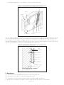
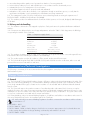
APPROVAL INSPECTION TESTING CERTIFICATION Rockwool Ltd 26/28 Hammersmith Grove Hammersmith London W6 7HA Tel: 01656 862621 Fax: 01656 862302 TECHNICAL APPROVALS FOR CONSTRUCTION Agrément Certificate 90/2437 e-mail: customer.support@rockwool.co.uk website: www.rockwool.co.uk Product Sheet 2 ROCKSHIELD EXTERNAL WALL INSULATION SYSTEMS THE ROCKSHIELD TC EXTERNAL WALL INSULATION SYSTEM This Agrément Certificate Product Sheet(1) relates to the Rockshield TC External Wall Insulation System, an external wall insulation system employing mineral wool insulation, with a glassfibre reinforcing mesh and render finishes. It is installed on the outside of external walls of masonry concrete construction on new or existing domestic and non-domestic buildings. The system is mechanically fixed with or without supplementary adhesive (Dryfix). (1) Hereinafter referred to as ‘Certificate’. CERTIFICATION INCLUDES: • factors relating to compliance with Building Regulations where applicable • factors relating to additional non-regulatory information where applicable • independently verified technical specification • assessment criteria and technical investigations • design considerations • installation guidance • regular surveillance of production • formal three-yearly review. KEY FACTORS ASSESSED Thermal performance — the system can be used to improve thermal performance of an external wall (see section 6). Strength and stability — the system can adequately resist wind loads and, in certain applications, impact damage (see section 7). Behaviour in relation to fire — the system has an external surface spread of flame Class 0 and can be used without height restriction (see section 8). Condensation — the system can contribute to limiting the risk of interstitial and surface condensation (see section 10). Durability — the design life of the system under typical conditions has been considered as part of this assessment (see section 12). The BBA has awarded this Certificate to the company named above for the system described herein. This system has been assessed by the BBA as being fit for its intended use provided it is installed, used and maintained as set out in this Certificate. On behalf of the British Board of Agrément Date of Second issue: 4 February 2013 Sean Moriarty — Head of Approvals Greg Cooper Originally certificated on 9 July 1990 Energy and Ventilation Chief Executive The BBA is a UKAS accredited certification body — Number 113. The schedule of the current scope of accreditation for product certification is available in pdf format via the UKAS link on the BBA website at www.bbacerts.co.uk Readers are advised to check the validity and latest issue number of this Agrément Certificate by either referring to the BBA website or contacting the BBA direct. British Board of Agrément Bucknalls Lane Watford Herts WD25 9BA ©2013 Page 1 of 15 tel: 01923 665300 fax: 01923 665301 e-mail: mail@bba.star.co.uk website: www.bbacerts.co.uk Regulations In the opinion of the BBA, the Rockshield TC External Wall Insulation System, if installed, used and maintained in accordance with this Certificate, will meet or contribute to meeting the relevant requirements of the following Building Regulations (the presence of a UK map indicates that the subject is related to the Building Regulations in the region or regions of the UK depicted): The Building Regulations 2010 (England and Wales) (as amended) Requirement: A1 Loading Comment: Requirement: B4(1) External fire spread The system can sustain and transmit wind loads to substrate wall. See section 7.4 of this Certificate. Comment: The system is classified Class 0 and, therefore, can meet this Requirement. See section 8.1 of this Certificate. Requirement: C2(b) Resistance to moisture Comment: The system provides a degree of protection against rain ingress. See sections 4.4 and 9.1 to 9.3 of this Certificate. Requirement: C2(c) Resistance to moisture Comment: The system contributes to minimising the risk of interstitial and surface condensation. See sections 10.1 and 10.3 of this Certificate. Requirement: L1(a)(i) Conservation of fuel and power Comment: Regulation: 7 Materials and workmanship Comment: Regulation: 26 CO2 emission rates for new buildings The system can contribute to meeting this Requirement. See sections 6.1 and 6.3 of this Certificate. The system is acceptable. See section 12.1 and the Installation part of this Certificate. The system can contribute to meeting this Regulation. See sections 6.1 and 6.3 of this Certificate. Comment: The Building (Scotland) Regulations 2004 (as amended) Regulation: 8(1)(2) Regulation: Standard: Fitness and durability of materials and workmanship The system can contribute to a construction meeting this Regulation. See sections 11 and 12.1 and the Installation part of this Certificate. Comment: 9 1.1 Building standards applicable to construction Structure The system can sustain and transmit wind loads to the substrate wall, with reference to clause 1.1.2(1)(2). See section 7.4 of this Certificate. Comment: Standard: 2.6 Spread to neighbouring buildings Comment: Standard: 2.7 Spread on external walls The system satisfies this Standard, with reference to clause 2.6.4(1)(2). See section 8.1 of this Certificate. The system incorporates materials which are classed as ‘non-combustible’ as defined in this Standard, with reference to clause 2.7.1(1)(2). See section 8.1 of this Certificate. Comment: Standard: 3.10 Standard: 3.15 6.1(a)(b) 6.2 7(a)(b) Comment: Statement of sustainability The system can contribute to meeting the relevant requirements of Regulation 9, Standards 1 to 6, and, therefore, will contribute to a construction meeting a bronze level of sustainability as defined in this Standard. See section 6.1 of this Certificate. Comment: Regulation: Carbon dioxide emissions Buildings insulation envelope The system can contribute to satisfying these Standards, with reference to clauses (or parts of) 6.1.1(1), 6.1.2(1)(2), 6.1.3(2), 6.1.5(2), 6.1.6(1), 6.2.1(1)(2), 6.2.3(1)(2), 6.2.4(2), 6.2.6(1)(2), 6.2.7(1)(2), 6.2.8(2), 6.2.9(1)(2), 6.2.10(1)(2), 6.2.11(1), 6.2.12(2) and 6.2.13(1). See sections 6.1 and 6.3 of this Certificate. Comment: Standard: Condensation Walls insulated with the system contribute to minimising the risk of interstitial and surface condensation and thus satisfy this Standard, with reference to clauses 3.15.1(1), 3.15.4(1) and 3.15.5(1). See sections 10.2 and 10.3 of this Certificate. Comment: Standard: Standard: Precipitation Walls insulated with the system will provide a degree of protection against rain ingress satisfying this Standard, with reference to clauses 3.10.1(1)(2) and 3.10.2(1)(2). See sections 4.4 and 9.1 to 9.3 of this Certificate. Comment: 12 Building standards applicable to conversions All comments given for these systems under Regulation 9, Standards 1 to 6, also apply to this Regulation, with reference to clause 0.12.1(1)(2) and Schedule 6(1)(2). (1) Technical Handbook (Domestic). (2) Technical Handbook (Non-Domestic). Page 2 of 15 The Building Regulations (Northern Ireland) 2012 Regulation: 23 Fitness of materials and workmanship Comment: Regulation: 28 Resistance to moisture and weather The system is acceptable. See sections 11 and 12.1 and the Installation part of this Certificate. The system provides a degree of protection against rain ingress and contributes to satisfy this Regulation. See sections 4.4 and 9.1 to 9.3 of this Certificate. Comment: Regulation: 29 Condensation The system contributes to minimising the risk of interstitial and surface condensation thus satisfying this Regulation. See section 10.3 of this Certificate. Comment: Regulation: 30 Stability Comment: Regulation: 36(a) External fire spread Comment: Regulation: Regulation: 39(a)(i) 40(2) Conservation measures Target carbon dioxide emission rate The system can sustain and transmit wind loads to the substrate wall. See section 7.4 of this Certificate. The system satisfies this Regulation. See section 8.1 of this Certificate. Comment: The system can contribute to satisfying these Regulations. See sections 6.1 and 6.3 of this Certificate. Construction (Design and Management) Regulations 2007 Construction (Design and Management) Regulations (Northern Ireland) 2007 Information in this Certificate may assist the client, CDM co-ordinator, designer and contractors to address their obligations under these Regulations. See section: 3 Delivery and site handling (3.2) of this Certificate. Additional Information NHBC Standards 2013 NHBC accepts the use of the Rockshield TC External Wall Insulation System, provided it is installed, used and maintained in accordance with this Certificate, in relation to NHBC Standards, Chapter 6.9 Curtain walling and cladding. Technical Specification 1 Description 1.1 The Rockshield TC External Wall Insulation System (see Figure 1) comprises: • Rockshield Adhesive Mortar— a mixture of white Portland cement, quartz sand and other additives supplied as a powder to which clean water is added • mineral wool insulation slabs: — Rockwool Dual Density — 1200 mm by 600 mm in a range of thicknesses between 50 mm and 200 mm with an average density of 110 kg·m–3 • • • • • • • • — Rockwool High Density — 1200 mm by 600 mm in a range of thicknesses between 30 mm and 40 mm, with a minimum density of 126 kg·m–3 and a minimum cross-breaking strength of 25 kN·m–2. They are used in reveals. The slabs are manufactured using conventional techniques and incorporate a phenolic resin binder and a mineral oil/water repellent fixing methods: there are two methods of fixing for the insulation boards: — Dryfix — insulation boards are mechanically fastened to the substrate — mechanically fixed with supplementary adhesive — where the substrate surface has a levelling coat applied or in high-rise applications, the insulation boards should be bonded to the wall with Rockshield Adhesive Mortar and secured with mechanical fixings mechanical fixings — polypropylene mechanical fixings, approved by the Certificate holder Rockshield TC Basecoat — a mixture of white Portland cement, quartz sand and other additives supplied as a powder to which clean water is added Rockshield Reinforcement Mesh — a one-metre wide mesh of multi-stranded glassfibres with a polymer coating and a nominal weight of 160 g·m–2 Rockshield Masonry Sealer — an emulsion containing fine quartz grains used as a bonding aid and pre-coat Rockshield Silcoplast finish — a silicone-bonded textured plaster supplied as a paste in three grades: 1.5 mm, 2.5 mm or 3.5 mm grain size. It is available in a range of colours Rockshield Colorsil — a micro-porous silicone-based façade paint used as a decorative finish ancillary materials include: — Rockshield Socket Profile — a metal trimming strip with a recessed water drip used as the base profile — Rockshield NB Edge Profile — a plastic meshed corner profile used as reinforcement for external corners and edges Page 3 of 15 — Rockshield Sealing Tape — a self-adhesive compressed PVC-U foam tape. Figure 1 Rockshield TC External Wall Insulation System insulation slabs adhesive substrate decorative finish topcoat reinforcement mesh mechanical fixing basecoat 1.2 The insulation slabs are bonded to the external surfaces of walls using the adhesive and secured with mechanical fixings at an average density of six fixings per square metre depending on individual specifications. The basecoat is trowel-applied to the insulation to an approximate thickness of from 3 mm to 6 mm and the reinforcement mesh is embedded immediately (see Figure 2). After drying for two days, a masonry sealer is applied to the basecoat, and the topcoat is trowel-applied to the thickness required (gauged by the grain size). Figure 2 Typical section at base level adhesive insulation slab mechanical fixing basecoat reinforcement mesh topcoat decorative finish socket profile substrate dpc 2 Manufacture 2.1 The mineral wool is manufactured from molten rock in a controlled way. 2.2 All components are subject to routine in-factory quality control. 2.3 As part of the assessment and ongoing surveillance of product quality, the BBA has: • agreed with the manufacturer the quality control procedures and product testing to be undertaken Page 4 of 15 • • • • • assessed and agreed the quality control operated over batches of incoming materials monitored the production process and verified that it is in accordance with the documented process evaluated the process for management of nonconformities checked that equipment has been properly tested and calibrated undertaken to carry out the above measures on a regular basis through a surveillance process, to verify that the specifications and quality control operated by the manufacturer are being maintained. 2.4 The management system of Rockwool Ltd has been assessed and registered as meeting the requirements of BS EN ISO 9001 : 2008 by BSI (Certificate: FM 02262). 2.5 The insulation product is manufactured at the Certificate holder’s premises in Pencoed, Bridgend, Mid-Glamorgan CF35 6NY. 3 Delivery and site handling 3.1 The insulation is delivered to site wrapped in polythene. Each pack carries the product identification and batch numbers. 3.2 Components are delivered to the site in bags and quantities as listed in Table 1. Each bag carries the BBA logo incorporating the number of this Certificate. Table 1 Component supply details Component Quantity and package Adhesive 25 kg bag TC Basecoat 25 kg bag Topcoat 25 kg tub Decorative paint 15 kg tub Masonry sealer 16 litre container Reinforcement mesh 50 m rolls by 1 m wide Mechanical fixings Boxed by manufacturer 3.3 The insulation should be stored on a firm, clean, level base, off the ground and under cover until required for use. Care must be taken when handling the insulation to avoid damage. 3.4 The renders must be stored in dry conditions, off the ground, and protected from moisture. 3.5 The Rockshield Silcoplast Finish and Rockshield Colorsil paint should be stored in a safe area, under cover and protected from excessive heat and frost at all times. Assessment and Technical Investigations The following is a summary of the assessment and technical investigations carried out on the Rockshield TC External Wall Insulation System. Design Considerations 4 General 4.1 The Rockshield TC External Wall Insulation System is effective in reducing the thermal transmittance (U value) of the walls of new and existing buildings. It is essential that the detailing techniques specified in this Certificate are carried out to a high standard if the ingress of water into the insulation is to be avoided and the full thermal benefit obtained from the system. 4.2 The system will improve the weather resistance of a wall and provide a decorative finish. However, it may be installed only where other routes for moisture penetration have been dealt with separately and where there are no signs of dampness on the inner surface of the wall, other than those caused solely by condensation. The system can be used to overcome condensation associated with the internal wall surface. 4.3 Existing buildings, subject to national Building Regulations, should have wall surfaces in accordance with section 13 Site survey and preliminary work in the Installation part of this Certificate. 4.4 New walls subject to national Building Regulations should be constructed in accordance with the relevant recommendations of: • BS 8000-3 : 2001 • BS EN 1996-1-2 : 2005 • BS EN 1996-2 : 2006, in that the designer should select a construction appropriate to the local wind-driven rain index, paying due regard to the design detailing, workmanship and materials to be used • BS EN 1996-3 : 2006. Page 5 of 15 4.5 Other walls, not subject to regulatory requirements, should also be built in accordance with the requirements in section 4.4. 4.6 When using the system, consideration must be given to the overall design to minimise the risk of condensation and the recommendations of BS 5250 : 2011 should be followed. 5 Practicability of installation The system should only be installed by installers who have been trained and approved by the Certificate holder (see section 15). 6 Thermal performance 6.1 Calculations of thermal transmittance (U value) should be carried out in accordance with BS EN ISO 6946 : 2007 and BRE Report (BR 443 : 2006) Conventions for U-value calculations, using the manufacturer’s declared thermal conductivity (90/90 value) of 0.036 W·m–1·K–1 for the insulations. 6.2 The U value of a completed wall will depend on the selected insulation thickness and fixing method, the insulating value of the substrate masonry and its internal finish. Calculated U values for example constructions are given in Table 2. Table 2 U values for Rockshield construction Insulation thickness (mm) U value (W·m–2·K–1) Rockwool Dual Density 30 – 40 – 50 0.51 60 0.45 70 0.40 80 0.36 90 0.33 100 0.30 110 0.28 120 0.26 130 0.24 140 0.22 150 0.21 160 0.20 170 0.19 180 0.18 190 0.17 200 0.16 6.3 The product can contribute to maintaining continuity of thermal insulation at junctions between elements. For Accredited Construction Details, the corresponding psi values in BRE Information Paper IP 1/06 Assessing the effects of thermal bridging at junctions and around openings, Table 3, may be used in carbon emission calculations in Scotland and Northern Ireland. Detailed guidance for other junctions and on limiting heat loss by air infiltration can be found in: England and Wales — Approved Documents to Part L and for new thermal elements to existing buildings, Accredited Construction Details (version 1.0). For new-build, see also SAP 2009, Appendix K, and the iSBEM User Manual Scotland — Accredited Construction Details (Scotland) Northern Ireland — Accredited Construction Details (version 1.0). 7 Strength and stability 7.1 Installations incorporating the insulation system can be designed as purely mechanically (Dryfix) to provide adequate resistance to withstand a wind load of up to 1.8 kPa (the limiting load is the bond strength between the insulation and the basecoat divided by safety factor of 5.7) as applicable in the UK. 7.2 Positive wind load (pressure) is transferred to the substrate wall directly via bearing and compression of the render and insulation. 7.3 Negative wind pressure (suction) is resisted by the bond between each component. The insulation boards are retained by the fixings and adhesive (where used). Page 6 of 15 7.4 The wind loads on the wall should be calculated in accordance with BS 8200 : 1985 and BS EN 1991-1-4 : 2005. Special consideration should be given to locations with high wind-load pressure coefficients as additional fixings may be necessary. In accordance with BS EN 1990 : 2002, it is recommended that a load factor of 1.5 is used to determine the ultimate wind load to be resisted by the system. 7.5 Assessment of structural performance for individual buildings must be carried out by a suitably qualified chartered engineer or other appropriately qualified person to confirm that: • the substrate wall has adequate strength to resist additional loads that may be applied as a result of installing the system, ignoring any contribution from the insulation system itself • the proposed system and associated fixing pattern and adhesive coverage (minimum 40%) (see Figure 3), provides adequate resistance to negative wind loads (based on the results of the site investigation). Figure 3 Typical fixing pattern with five fixings and 40% supplementary adhesive or without adhesive 7.6 Provided the substrate wall is suitable and an appropriate fixing is used, the mechanical fixings will transfer the weight of the render insulation system to the substrate wall. The number of fixings and the span between fixings should be determined by the system designer. The fixing must be selected to give adequate support to the weight of the system at the minimum spacing given in this Certificate. A minimum of one metal fixing per square metre must be used where required to satisfy the fire regulations (see section 8). 7.7 An appropriate number of site-specific pull-out tests should be conducted on the substrate of the building to determine the minimum resistance to failure of the fixings. The characteristic pull-out resistance should be determined in accordance with the guidance given in ETAG 014 : 2002, Annex D, using 60% of the mean value of the five smallest measured values at the ultimate load. The design pull-out resistance per square metre is the mean pull-out resistance multiplied by the number of fixings and divided by a factor of safety of 2. 7.8 The resistance forces data given in Table 3 are the results of calculations based upon: • fixings arranged in the pattern described and shown in section 7.5 and Figure 3 • pull-over resistances are characteristic values determined by the BBA from tests on anchors with 60 mm diameter plates • an appropriate number of site-specific tests (see section 7.7). Page 7 of 15 Table 3 Example calculation to establish the ultimate wind load capacity Characteristic (unit) Value Thickness(1) (mm) Characteristic pull-over resistance(2) (per anchor) (N) Factor of safety Design pull-over resistance(3) (N) Characteristic anchor pull-out resistance(4) (per anchor) (N) Factor of safety(5) Design pull-out resistance (per anchor) (N) Limiting design value(6) (per anchor) (N) Limiting design value per board(7) (with 4 fixings) (N) Area of board (m2) Limiting pressure (kN·m–2) 50 260 2.5 104 750 2 375 104 520 0.72 0.72 (1) Insulation board size: 1200 mm by 600 mm. (2) Pull-over resistance from the head of the fixing; anchor 1 = Ejot TID-T with a 60 mm anchor plate, anchor 2 = Ejot NTU95 with a 60 mm anchor plate. (3) Safety factor 3. (4) Example value only. In practice this will be obtained from site-specific pull-out test (see section 7.7). (5) See section 7.7. (6) The lesser of the board design pull-over resistance and the anchor design pull-out resistance. (7) Board design pull-out resistance multiplied by the number of fixings, based upon the limiting resistance. 7.9 The strength and stability of the system were assessed assuming mechanical fixing only (ie disregarding supplementary adhesive). Impact loading 7.10 Hard body impact tests were carried out in accordance with MOAT No 43 : 1987. The systems are suitable for use in use categories I to III as defined in ETAG 004 : 2011, section 6.1.3.3, or categories A to D(1) as defined in BS 8200 : 1985, Table 2. (1) Zone of wall up to 1.5 m above pedestrian or floor level in location categories A to D is defined as: • Category A — readily accessible to the public and others with little incentive to exercise care; prone to vandalism and abnormally rough use, eg external walls of housing and public buildings in vandal prone areas • Category B — readily accessible to the public and others with little incentive to exercise care; risk of accidents occurring and of misuse, eg walls adjacent to pedestrian thoroughfares or playing fields when not in category A • Category C — accessible primarily to those with some incentive to exercise care. Some chance of accident occurring and of misuse, eg walls adjacent to private open gardens. Back walls of balconies • Category D — only accessible, but not near a common route, to those with high incentive to exercise care. Small chance of accident occurring or of misuse, eg walls adjacent to small fenced decorative garden with no through paths. 8 Behaviour in relation to fire 8.1 The insulation is classified as non-combustible to BS EN 13501-1 : 2007. The external surfaces of the system are classified as Class 0 or ‘low risk’ as defined in the documents supporting the national Building Regulations. The system, therefore, may be used without height restriction, subject to the provisions of: England and Wales — Approved Document B, Volume 1, paragraph 8.4, and Volume 2, paragraphs 12.5 and 12.6 (see also Diagram 40) Scotland — Mandatory Standards 2.6 and 2.7, clauses 2.6.1(1)(2) to 2.6.5(1)(2), 2.6.6(2), 2.6.7(2), 2.7.1(1)(2) and 2.7.2(2) respectively, and Annexes 2.C(1) and 2.E(2) (1) Technical Handbook (Domestic). (2) Technical Handbook (Non-Domestic). Northern Ireland — Technical Booklet E, paragraph 5.3 (see also Diagram 5.1). 8.2 The behaviour of fire in external wall insulation is the subject of recommendations by the Building Research Establishment which, for this system, makes no restriction on the height of building to be treated. The system complies with BS 8414-1 : 2002. 9 Watertightness 9.1 The system will provide a degree of protection against rain ingress. However, care should be taken to ensure that walls are adequately weathertight prior to its application. 9.2 Designers and installers should take particular care in detailing around openings, penetrations and movement joints to minimise the risk of rain ingress. 9.3 Further guidance must be sought in accordance with BS EN 1996-1-1 : 2005, BS EN 1996-2 : 2006 and BS EN 1996-3 : 2006 for use in exposure categories up to ‘severe’. Page 8 of 15 10 Condensation Surface condensation 10.1 Walls will limit the risk of surface condensation adequately when the thermal transmittance (U value) does not exceed 0.7 W·m–2·K–1 at any point and the junctions with other elements are designed in accordance with the relevant requirements of the publications referred to in section 6. 10.2 Walls will adequately limit the risk of surface condensation when the thermal transmittance (U value) does not exceed 1.2 W·m–2·K–1 at any point. Guidance may be obtained from BS 5250 : 2011, Annex G, and BRE Report (BR 262 : 2002). Interstitial condensation 10.3 Walls incorporating the system will adequately limit the risk of interstitial condensation when they are designed and constructed in accordance with BS 5250 : 2011 (Annexes D and G). 11 Maintenance Regular checks should be made on the installed system, particularly at joints, to ensure that ingress of water does not occur. This includes checks on joints in the system and on any penetrations through the system, such as those caused by external plumbing fitments, to identify leakage of rainwater into the system, enabling steps to be taken to correct the defects. Necessary repairs should be carried out immediately. 12 Durability 12.1 The results of accelerated ageing tests in accordance with MOAT No 22 : 1988 indicate that the system is durable. The system should remain effective for at least 30 years, provided any damage to the surface finish is repaired immediately, and regular maintenance is undertaken including checks on joints in the system (see section 11). 12.2 The finishes may become soiled in time, the rate depending on locality. 12.3 Tests conducted by the BBA indicate that when used in situations where walls are exposed but have some protection, eg walls of private dwellings and walls of communal dwellings above ground-floor level, the system has adequate resistance to possible damage. In other situations, eg walls of public buildings at ground-floor level, precautions may be required to reduce the risk of damage. Further information may be obtained from BRE Current Paper CP 6 : 1981 Assessment of external walls : hard body impact resistance. Installation 13 Site survey and preliminary work 13.1 A pre-installation survey of the property is carried out to determine suitability for treatment and any repairs necessary to the building structure before application of a system. A specification is prepared for each elevation of the building indicating: • the position of beads • detailing around windows, doors and at eaves • dpc level • exact position of expansion joints • areas where flexible sealants must be used • any alterations to external plumbing. 13.2 The survey should include tests conducted on the walls of the building by the Certificate holder or their approved suppliers to determine the pull-out resistance of the proposed mechanical fixings. An assessment and recommendation is made on the type and number of fixings required to withstand the building’s expected wind loading based on calculations using the test data, the relevant wind speed data for the site, and in the absence of a formal requirement, a safety factor of 1.5 should be used. 13.3 All necessary repairs to the building structure are completed before installation of the system. 13.4 Surfaces should be sound, clean, and free from loose material. The flatness of surfaces must be checked; this may be achieved using a straight edge spanning the storey height. Any excessive irregularities, ie greater than 10 mm, must be made good prior to installation to ensure that the insulation boards are installed with a smooth, in-plane finished surface. 13.5 Where surfaces are covered with an existing rendering it is essential that the bond between the background and the render is adequate. All loose areas should be hacked off and reinstated. 13.6 On existing buildings, purpose-made sills must be fitted to extend beyond the finished face of the system by a minimum of 30 mm. New buildings should incorporate suitably deep sills. Page 9 of 15 13.7 It is recommended that external plumbing be removed and alterations made to underground drainage, where appropriate, to accommodate repositioning on the finished face of the system. 13.8 New buildings should be of sound masonry or dense concrete construction. 13.9 Internal wet work, eg screeding or plastering, should be completed and allowed to dry prior to the application of the system. 14 Procedure General 14.1 Application is carried out in accordance with the Certificate holder’s current installation instructions. 14.2 Application of coating materials must not be carried out at temperatures below 5°C or above 30°C, nor if exposure to frost is likely, and the coating must be protected from rapid drying. Therefore, weather conditions should be monitored to ensure correct curing conditions. 14.3 All rendering should be in accordance with the relevant recommendations of BS EN 13914-1 : 2005. Positioning and securing insulation boards 14.4 The base profile is secured to the external wall above the damp-proof course using the approved profile fixings at approximately 300 mm centres. 14.5 The adhesive is prepared for use by mixing the contents of each 25 kg bag with approximately six litres of water using an electrically driven paddle mixer to give a smooth, workable consistency. Care should be taken not to over-mix. 14.6 The adhesive is applied to the back of the slabs by either a comb to achieve a full bond, or as dabs for an uneven background. 14.7 The insulation slabs should be pressed firmly to the substrate immediately after application of the adhesive. Any delay may result in a weak bond. 14.8 The first run of insulation is positioned on the base profile. Holes are drilled into the substrate to a minimum depth of 50 mm through the insulation at 150 mm from each corner of each slab and at positions that will allow a minimum of eight fixings per square metre. The mechanical fixings are inserted and tapped firmly into place, securing the insulation to the substrate. Subsequent rows of slabs are positioned so that the joints are staggered and overlapped at the building corners (see Figure 4). Figure 4 Arrangement of insulation slabs 2 mechanical fixings 8 per m 12 00 mm m 0m 60 14.9 Care must be taken to ensure that all slab edges are butted tightly together, and alignment should be checked as work proceeds. 14.10 To fit around details such as doors and windows, insulation slabs may be cut with a sharp knife or a fine-tooth saw. If required, purpose-made window sills are fitted. They are designed to prevent water ingress and incorporate drips to shed water clear of the system. 14.11 Installation continues until the whole wall is completely covered including, where appropriate, the building soffits. Movement joints 14.12 Movement joints in the substrate must be continued through the system. The joint detail using purpose-made metal trims is illustrated in Figure 5. Page 10 of 15 Figure 5 Vertical movement joint edge profile backer rod sealant edge profile Reinforcing 14.13 The basecoat is prepared by mixing the contents of each 25 kg bag with approximately six litres of cold, clean water using the same method as for the adhesive. 14.14 The basecoat render is trowel-applied to the surface of the dry insulation to a minimum thickness of 3 mm and a maximum thickness of 6 mm. The mesh is bedded immediately into the basecoat with 100 mm laps at joints. Additional pieces of reinforcing mesh are used diagonally at the corners of openings, as shown in Figure 6. Figure 6 Additional reinforcement at openings mesh 0 50 25 0 m m m m 45º 14.15 Prior to the render coat, a bead of clear silicone rubber mastic is gun-applied at window and door frames, overhanging eaves, gas and electric meter boxes, wall vents or where the render abuts any other building material or surface. 14.16 Angle beads are fixed to all building corners and to door and window heads and jambs. 14.17 Expansion beads are fixed vertically in agreed positions. These beads are positioned at approximately sevenmetre centres along a building, the centres depending on the individual requirements of each job. 14.18 Stop beads are positioned vertically, eg at party wall positions where the adjoining house does not require treatment. Rendering and finishing 14.19 The drying period of any render will depend on weather conditions; however, the basecoat must be left to harden for at least two days before the sealer is applied by roller or brush. The sealer is allowed to dry before application of the topcoat. The topcoat is ready mixed in 25 kg tubs. The topcoat is trowel-applied to thicknesses of 1.5 mm, 2.5 mm or 3.5 mm depending on specification 14.20 To prevent the finish from drying too rapidly, continuous surfaces should be completed without a break. 14.21 Depending on weather conditions, the topcoat should be allowed to dry for at least two days before application of Rockshield Colorsil decorative finish. 14.22 At the tops of wall, the system should be protected by an adequate overhang or by an adequately sealed purpose-made flashing (see Figure 7). Page 11 of 15 Figure 7 Roof eaves detail insulating slabs 14.23 Care should be taken in the detailing of the system around openings and projections (see Figures 8, 9, 10 and 11). Figure 8 Insulated window detail sealing tape edge profile Figure 9 Uninsulated window reveal detail edge profile Page 12 of 15 Figure 10 Window head detail sealing tape edge profile Figure 11 Window sill detail sealant 14.24 On completion of the installation, external fittings, eg rainwater goods, are refixed through the system into the substrate. Care must be taken not to overtighten the fixings which could cause damage. Guidance from the Certificate holder must be sought in terms of the appropriate number and type fixings used, which are outside the scope of this Certificate. 15 General Approved installers 15.1 Application of the system, within the context of this Certificate, is carried out by approved installers, an approved installer being a firm which: • is employing operatives who have been trained and approved by the Certificate holder to install the system and who have been issued with the appropriate training cards by them • has undertaken to comply with the Certificate holder’s application procedure, which contains the requirement for each application team to include at least one member with a training card, and • is subject to supervision by the Certificate holder, including site inspections. 15.2 Firms approved by the Certificate holder may also be approved to install the system under the BBA’s Assessment and Surveillance Scheme for Installers of External Wall Insulation Systems. In addition to the requirements given in section 15.1, these installers will be subject to site and office inspections by the BBA prior to approval and while they remain approved. Page 13 of 15 Technical Investigations 16 Tests 16.1 Tests were carried out on the system in accordance with MOAT No 22 : 1988 to determine: • component characterisation • flexural and compressive strength of renders • density of slab • heat/spray cycling • resistance to freeze/thaw • impact resistance • water absorption of render • water vapour permeability. 16.2 An examination was made of data relating to: • non-combustibility tests to BS 476-4 : 1970 • fire propagation tests to BS 476-6 : 1989 • surface spread of flame tests to BS 476-7 : 1997 • pull-out strength of fixings • durability of finish • thermal conductivity to BS EN 12667 : 2001. 17 Investigations 17.1 The manufacturing process, the methods adopted for quality control of manufactured and brought-in components, and details of the quality and composition of materials used, was examined. 17.2 An assessment into the risk of interstitial condensation was undertaken. 17.3 The practicability of installation and the effectiveness of detailing techniques were examined. 17.4 Visits were made to existing sites to assess the performance of the product in use. Bibliography BS 476-4 : 1970 Fire tests on building materials and structures — Non-combustibility test for materials BS 476-6 : 1989 Fire tests on building materials and structures — Method of test for fire propagation for products BS 476-7 : 1997 Fire tests on building materials and structures — Method of test to determine the classification of the surface spread of flame of products BS 5250 : 2011 Code of practice for control of condensation in buildings BS 8000-3 : 2001 Workmanship on building sites — Code of practice for masonry BS 8200 : 1985 Code of practice for design of non-loadbearing external vertical enclosures of buildings BS 8414-1 : 2002 Fire performance of external cladding systems — Test methods for non-loadbearing external cladding systems applied to the face of a building BS EN 1990 : 2002 Eurocode — Basis of structural design BS EN 1991-1-4 : 2005 Eurocode 1 : Actions on structures — General actions — Wind actions BS EN 1996-1-1 : 2005 Eurocode 6 : Design of masonry structures — General rules for reinforced and unreinforced masonry structures BS EN 1996-1-2 : 2005 Eurocode 6 : Design of masonry structures — General rules — Structural fire design BS EN 1996-2 : 2006 Eurocode 6 : Design of masonry structures — Design considerations, selection of materials and execution of masonry BS EN 1996-3 : 2006 Eurocode 6 : Design of masonry structures : Simplified calculation methods for unreinforced masonry structures BS EN 12667 : 2001 Thermal performance of building materials and products — Determination of thermal resistance by means of guarded hot plate and heat flow meter methods — Products of high and medium thermal resistance BS EN 13501-1 : 2007 Fire classification of construction products and building elements — Classification using test data from reaction to fire tests BS EN 13914-1 : 2005 Design, preparation and application of external rendering and internal plastering — External rendering BS EN ISO 6946 : 1997 Building components and building elements — Thermal resistance and thermal transmittance — Calculation method BS EN ISO 9001 : 2008 Quality management systems — Requirements Page 14 of 15 ETAG 004 : 2011 Guideline for European Technical Approval of External Thermal Insulation Composite Systems with Rendering ETAG 014 : 2002 Guideline for European Technical Approval of Plastic Anchors for fixing of External Thermal Insulation Composite Systems with Rendering MOAT No 22 : 1988 UEAtc Directives for the Assessment of External Insulation Systems for Walls (Expanded Polystyrene Insulation Faced with a Thin Rendering) MOAT No 43 : 1987 UEAtc Directives for Impact Testing Opaque Vertical Building Components Conditions of Certification 18 Conditions 18.1 This Certificate: • relates only to the product/system that is named and described on the front page • is issued only to the company, firm, organisation or person named on the front page — no other company, firm, organisation or person may hold or claim that this Certificate has been issued to them • is valid only within the UK • has to be read, considered and used as a whole document — it may be misleading and will be incomplete to be selective • is copyright of the BBA • is subject to English Law. 18.2 Publications, documents, specifications, legislation, regulations, standards and the like referenced in this Certificate are those that were current and/or deemed relevant by the BBA at the date of issue or reissue of this Certificate. 18.3 This Certificate will remain valid for an unlimited period provided that the product/system and its manufacture and/or fabrication, including all related and relevant parts and processes thereof: • are maintained at or above the levels which have been assessed and found to be satisfactory by the BBA • continue to be checked as and when deemed appropriate by the BBA under arrangements that it will determine • are reviewed by the BBA as and when it considers appropriate. 18.4 The BBA has used due skill, care and diligence in preparing this Certificate, but no warranty is provided. 18.5 In issuing this Certificate, the BBA is not responsible and is excluded from any liability to any company, firm, organisation or person, for any matters arising directly or indirectly from: • the presence or absence of any patent, intellectual property or similar rights subsisting in the product/system or any other product/system • the right of the Certificate holder to manufacture, supply, install, maintain or market the product/system • actual installations of the product/system, including their nature, design, methods, performance, workmanship and maintenance • any works and constructions in which the product/system is installed, including their nature, design, methods, performance, workmanship and maintenance • any loss or damage, including personal injury, howsoever caused by the product/system, including its manufacture, supply, installation, use, maintenance and removal • any claims by the manufacturer relating to CE marking. 18.6 Any information relating to the manufacture, supply, installation, use, maintenance and removal of this product/ system which is contained or referred to in this Certificate is the minimum required to be met when the product/system is manufactured, supplied, installed, used, maintained and removed. It does not purport in any way to restate the requirements of the Health and Safety at Work etc. Act 1974, or of any other statutory, common law or other duty which may exist at the date of issue or reissue of this Certificate; nor is conformity with such information to be taken as satisfying the requirements of the 1974 Act or of any statutory, common law or other duty of care. British Board of Agrément Bucknalls Lane Watford Herts WD25 9BA ©2013 Page 15 of 15 tel: 01923 665300 fax: 01923 665301 e-mail: mail@bba.star.co.uk website: www.bbacerts.co.uk