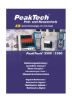
Download PeakTech® 3440
Transcript
PeakTech® 3440 Bedienungsanleitung / Operation Manual Grafikmultimeter / Graphical Multimeter 1. Sicherheitshinweise Dieses Gerät erfüllt die EU-Bestimmungen 2004/108/EG (elektromagnetische Kompatibilität) und 2006/95/EG (Niederspannung) entsprechend der Festlegung im Nachtrag 2004/22/EG (CE-Zeichen). Überspannungskategorie III 1000V; Überspannungskategorie IV 600V; Verschmutzungsgrad 2. CAT I: Signalebene, Telekommunikation, elektronische Geräte mit geringen transienten Überspannungen CAT II: Für Hausgeräte, Netzsteckdosen, portable Instrumente etc. CAT III: Versorgung durch ein unterirdisches Kabel; Festinstallierte Schalter, Sicherungsautomaten, Steckdosen oder Schütze CAT IV: Geräte und Einrichtungen, welche z.B. über Freileitungen versorgt werden und damit einer stärkeren Blitzbeeinflussung ausgesetzt sind. Hierunter fallen z.B. Hauptschalter am Stromeingang, Überspannungsableiter, Stromverbrauchszähler und Rundsteuerempfänger Zur Betriebssicherheit des Gerätes und zur Vermeidung von schweren Verletzungen durch Strom- oder Spannungsüberschläge bzw. Kurzschlüsse sind nachfolgend aufgeführte Sicherheitshinweise zum Betrieb des Gerätes unbedingt zu beachten. Schäden, die durch Nichtbeachtung dieser Hinweise entstehen, sind von Ansprüchen jeglicher Art ausgeschlossen. Dieses Gerät darf nicht in hochenergetischen Schaltungen verwendet werden. Gerät nicht auf feuchten oder nassen Untergrund stellen. Keine Flüssigkeiten auf dem Gerät abstellen (Kurzschlussgefahr beim Umkippen des Gerätes) -1- Gerät nicht in der Nähe starker magnetischer Felder (Motoren, Transformatoren usw.) betreiben maximal zulässige Eingangsspannung von 1000V DC/AC nicht überschreiten. maximal zulässige Eingangswerte unter keinen Umständen überschreiten (schwere Verletzungsgefahr und/oder Zerstörung des Gerätes) Die angegebenen maximalen Eingangsspannungen dürfen nicht überschritten werden. Falls nicht zweifelsfrei ausgeschlossen werden kann, dass diese Spannungsspitzen durch den Einfluss von transienten Störungen oder aus anderen Gründen überschritten werden muss die Messspannung entsprechend (10:1) vorgedämpft werden. Nehmen Sie das Gerät nie in Betrieb, wenn es nicht völlig geschlossen ist. Defekte Sicherungen nur mit einer dem Originalwert entsprechenden Sicherung ersetzen. Sicherung oder Sicherungshalter niemals kurzschließen. Vor dem Umschalten auf eine andere Messfunktion Prüfleitungen oder Tastkopf von der Messschaltung abkoppeln. Keine Spannungsquellen über die µA/mA, 10A – und COM-Eingänge anlegen. Bei Nichtbeachtung droht Verletzungsgefahr und/oder die Gefahr der Beschädigung des Multimeters. Der 10A-Bereich ist durch eine 10A/1000V-Sicherung abgesichert. Bei der Widerstandsmessungen keine Spannungen anlegen! Keine Strommessungen im Spannungsbereich (V/Ω) vornehmen. -2- Gerät, Prüfleitungen und sonstiges Zubehör vor Inbetriebnahme auf eventuelle Schäden bzw. blanke oder geknickte Kabel und Drähte überprüfen. Im Zweifelsfalle keine Messungen vornehmen. Verwenden Sie ausschließlich 4mmSicherheitstestkabelsätze, um eine einwandfreie Funktion des Gerätes zu gewährleisten. Messarbeiten nur in trockener Kleidung und vorzugsweise in Gummischuhen bzw. auf einer Isoliermatte durchführen. Messspitzen der Prüfleitungen nicht berühren. Warnhinweise am Gerät unbedingt beachten. Gerät darf nicht unbeaufsichtigt betrieben werden Bei unbekannten Messgrößen vor der Messung auf den höchsten Messbereich umschalten. Gerät keinen extremen Temperaturen, direkter Sonneneinstrahlung, extremer Luftfeuchtigkeit oder Nässe aussetzen. Starke Erschütterung vermeiden. Heiße Lötpistolen aus der unmittelbaren Nähe des Gerätes fernhalten. Vor Aufnahme des Messbetriebes sollte das Gerät auf die Umgebungstemperatur stabilisiert sein (wichtig beim Transport von kalten in warme Räume und umgekehrt) Überschreiten Sie bei keiner Messung den eingestellten Messbereich. Sie vermeiden so Beschädigungen des Gerätes. Drehen Sie während einer Strom – oder Spannungsmessung niemals am Messbereichswahlschalter, da hierdurch das Gerät beschädigt wird. Messungen von Spannungen über 35V DC oder 25V AC nur in Übereinstimmung mit den relevanten Sicherheitsbestimmungen vornehmen. Bei höheren Spannungen können besonders gefährliche Stromschläge auftreten. -3- Laden Sie den Akku wieder auf, sobald das Batteriesymbol „BAT“ aufleuchtet. Mangelnde Batterieleistung kann unpräzise Messergebnisse hervorrufen. Stromschläge und körperliche Schäden können die Folge sein. Sollten Sie das Gerät für einen längeren Zeitraum nicht benutzen, entnehmen Sie die Batterie aus dem Batteriefach. Säubern Sie das Gehäuse regelmäßig mit einem feuchten Stofftuch und einem milden Reinigungsmittel. Benutzen Sie keine ätzenden Scheuermittel. Dieses Gerät ist ausschließlich für Innenanwendungen geeignet. Vermeiden Sie jegliche Nähe zu explosiven und entflammbaren Stoffen. Öffnen des Gerätes und Wartungs – und Reparaturarbeiten dürfen nur von qualifizierten Service-Technikern durchgeführt werden. Gerät nicht mit der Vorderseite auf die Werkbank oder Arbeitsfläche legen, um Beschädigung der Bedienelemente zu vermeiden. Keine technischen Veränderungen am Gerät vornehmen. - Messgeräte gehören nicht in Kinderhände – Reinigung des Gerätes: Gerät nur mit einem feuchten, fusselfreien Tuch reinigen. Nur handelsübliche Spülmittel verwenden. Beim Reinigen unbedingt darauf achten, dass keine Flüssigkeit in das Innere des Gerätes gelangt. Dies könnte zu einem Kurzschluss und zur Zerstörung des Gerätes führen. -4- 1.1 Einleitung Das PeakTech® 3440 ist ein professionelles True RMS DigitalMultimeter mit TFT-Farb-LCD-Display und bietet einen A/D-Wandler mit einer schnellen Messrate, hoher Genauigkeit, integriertem Datenlogger und Trend-Capture Funktionen. Es können alle möglichen Unterbrechungen an Ausrüstungen oder Anlagen verfolgt, beobachten und behoben werden. Mit diesem Gerät sind Probleme an Produktionsanlagen / Ausrüstungen leicht zu finden und zu lösen. Es ist mit einer Bluetooth-Technologie und einem internen Speicher für Messwerte ausgestattet und bietet einen hohen Sicherheitsstandard für jegliche Messanwendung. Dieses Messgerät misst AC / DC-Spannung, AC / DC Strom, Widerstand, Kapazität, Frequenz (elektrischen und elektronischen), Arbeitszyklus, Diodentest, Isolationstest, Durchgangs- und Thermoelement-Temperatur. Es kann Daten speichern und wieder abrufen. Es verfügt über ein wasserdichtes, robustes Design für den harten Einsatz. 1.2 Maximal zulässige Eingangswerte Funktion DCV / ACV DCA / ACA (µA/mA) DCA / ACA (10 A) Widerstand Diode / Durchgang Kapazität Frequenz Temperatur Überlastschutz 1000V DC/AC eff 800mA / 1000V 10 A / 1000V 1000V DC/AC eff 1000V DC/AC eff 1000V DC/AC eff 1000V DC/AC eff 1000V DC/AC eff -5- 1.3. Sicherheitssymbole und Hinweise am Gerät Gerät ist TÜV/GS geprüft; TÜV-Rheinland Achtung! Entsprechende(n) Abschnitt(e) in der Bedienungsanleitung nachlesen. Nichtbeachtung birgt Verletzungsgefahr und/oder die Gefahr der Beschädigung des Gerätes. MAX 1000V max. zulässige Spannungsdifferenz von 1000 V DC/ACeff zwischen COM-/ V-/ bzw. Ohm-Eingang und Erde aus Sicherheitsgründen nicht überschreiten. Gefährlich hohe Spannung zwischen den Eingängen. Extreme Vorsicht bei der Messung. Eingänge und Messspitzen nicht berühren. Sicherheitshinweise in der Bedienungsanleitung beachten! ~ Wechselspannung – Strom (AC) Gleichspannung – Strom (DC) AC oder DC Erde Doppelt isoliert Sicherung Entspricht den Richtlinien der europäischen Union Achtung! Mögliche Gefahrenquelle. Sicherheitsvorschriften unbedingt beachten. Bei Nichtbeachtung besteht u. U. Verletzungs- oder Lebensgefahr und/oder die Gefahr der Beschädigung des Gerätes. -6- 2. Bedienelemente und Anschlüsse am Gerät 1 2 3 5 4 6 -7- 1. TFT/LCD-Display mit einer Anzeige von max. 50.000 2. Funktionstasten F1, F2, F3, F4 zur Auswahl und Steuerung über Menüfunktionen 3. HOLD/REL-Taste: messfunktion 4. Funktions-/Bereichswahlschalter: Zur Auswahl gewünschten Messfunktion bzw. des Messbereiches 5. RANGE-Taste: Umschaltung auf manuelle Bereichswahl 6. COM-Eingangsbuchse: Eingangsbuchse schwarze Prüfleitung für alle Messfunktionen Messwerthaltefunktion, Relativwert- für der die V//Hz/-II-/ -Eingangsbuchse Eingangsbuchse für rote Prüfleitung für alle Messfunktionen, ausgenommen Strommessungen. µA/mA-Eingangsbuchse Eingangsbuchse für AC/DCStrommessungen von < 500mA 10A-Eingangsbuchse Eingangsbuchse Strommessungen von 500mA bis 10A. -8- für AC/DC- 3. Hinweise zur Inbetriebnahme des Gerätes Achtung! Messungen an Schaltungen mit hohen Spannungen (AC und DC) mit äußerster Vorsicht und nur in Übereinstimmung mit den relevanten Sicherheitsbestimmungen vornehmen. Gerät nach Beendigung des Messbetriebes stets ausschalten. Das Messgerät verfügt über eine interne Abschaltautomatik die das Gerät automatisch max. 30 Minuten nach dem letzten Betätigen einer Taste ausschaltet. Bei Aufleuchten des Überlaufsymbols OL übersteigt der gemessene Wert den gewählten Eingangsbereich. Bei Umschaltung auf einen höheren Messbereich erlischt die Anzeige automatisch. 3.1. Vorbereitung zum Messbetrieb 1. Prüfen Sie vor der Messung die Versorgungsspannung des Akkus. Ist sie zu schwach, erscheint das Batteriesymbol rechts oben und der Akku muss wieder aufgeladen werden. 2. Das Warndreieck neben den Eingangsbuchsen soll Sie warnen, dass Messspannung oder Messstrom zum Schutz der internen Schaltung nicht den angegebenen Wert übersteigen dürfen. 3. Der Funktionswahlschalter sollte vor der Messung auf den gewünschten Bereich eingestellt werden. Hinweis: In den niederen AC-/DC-Messbereichen erscheint bei nicht angeschlossenen Prüfleitungen u.U. ein beliebig sich ändernder Wert in der LCD-Anzeige. Dies ist bei Geräten mit hoher Empfindlichkeit normal und für die Messgenauigkeit bedeutungslos. -9- 3.2. Umschaltung von automatischer auf manuelle Bereichswahl Beim Einschalten des Gerätes wird immer die automatische Bereichswahl aktiviert. Die automatische Bereichswahl erleichtert den Messbetrieb und garantiert optimale Messergebnisse. Zur Umschaltung auf manuelle Bereichswahl wie beschrieben verfahren: 1. Taste RANGE drücken. Beim Drücken der Taste erlischt die Anzeige AUTO und der zuletzt gewählte Bereich bleibt weiterhin aktiviert. 2. Taste RANGE ggf. mehrmals, bis zum Erhalt des gewünschten Bereiches, drücken. 3. Zur Rückkehr zu automatischer Bereichswahl Taste RANGE für ca. 2 Sekunden gedrückt halten. Die Anzeige für automatische Bereichswahl „AUTO“ leuchtet auf. -10- 4. Merkmale 4.1. Erklärung der Drucktaster Die 6 Drucktasten auf der Frontplatte des Multimeters aktivieren Funktionen, die die Messfunktionen, welche über den Drehschalter ausgewählt wurden, erweitern. Mit den Tastern kann nun innerhalb der Menüs navigiert werden. F1: Standardschalter auf Graph-Messung. F2: Standard-Funktion bezogen auf die jeweils gewählte Messfunktion F3: Standardeinstellung für den Speicher-Modus und Voreinstellung der Anzeige in allen Messfunktionen, sowie wiedereinschalten nachdem die Abschaltautomatik das Gerät abgeschaltet hat. F4: MIN/MAX startet und stoppt die Minimalwert - / Maximalwertmessfunktion. RANGE: Durch drücken der RANGE-Taste wird der manuelle Messbereich in der aktuellen Messfunktion gewählt. Wird die RANGE-Taste 2 Sekunden gedrückt gehalten, kehrt das Gerät wieder in die automatische Bereichswahl zurück. HOLD / Durch Drücken der HOLD/REL-Taste wird der aktuell REL: angezeigte Messwert im Display eingefroren. Wir die HOLD/REL-Taste 2 Sekunden gedrückt gehalten, wechselt das Gerät in die Relativwertmessfunktion. -11- 4.2. Funktionsweise der Anzeige 1. Zuordnung der Drucktasten: zeigt die Funktion der Drucktaste direkt unterhalb der angezeigten Markierung 2. Analoge Balkengrafik (Tendenzanzeige). 3. Anzeige der Polarität des Eingangssignals („-„ bedeutet negative Polarität) 4. Anzeige des aktuellen Messwertes. 5. Anzeige der Bereichswahl: automatische Bereichswahl oder manuelle Bereichswahl 6. Anzeige der Uhrzeit. 7. Batteriezustandsanzeige: gibt den momentanen Ladezustand des Akkus an. 8. Symbol für den akustischen Signalton zeigt an, dass der akustische Signalton des Messgerätes aktiviert ist (nicht mit der Durchgangsprüffunktion verbunden). 9. Maßeinheiten der gewählten Messfunktion -12- 4.3. Funktionsweise des Drehwahlschalters Wählen Sie eine primäre Messfunktion, indem Sie den Drehschalter auf eine der möglichen Funktionen drehen. Das Messgerät stellt für jede einzelne Messfunktion eine Standardanzeige (Messbereich, Maßeinheiten und Modifikatoren). Ausgewählte Tastenoptionen werden nicht auf andere Messfunktionen übertragen. V~ V– mV / Hz% TEMP A mA 4 - 20 mA% µA / CAP Spannungsmessfunktion AC Spannungsmessfunktion DC und AC+DC DC/AC milli-Volts Messfunktion Widerstand, Diodentest, Kapazität und Durchgangsprüffunktion Frequenzmessfunktion Temperatur-Messfunktion AC/DC Strommessfunktion AC/DC mA-Strommessfunktion % 4-20mA Messfunktion AC/DC µA AStrommessfunktionup to 5.000 µA -13- 4.4. Verwenden der Eingangsbuchsen Für alle Funktionen, außer der Strommessfunktion werden die V//CAP/Hz%/Temp und COM-Eingangsanschlüsse verwendet. 10A Eingang für 0 A bis 10,00 A Strom (20 VA Überlast für 30 Sekunden ein, 10 Minuten aus) µA mA Eingang für 0 A bis 500 mA Strommessungen COM Masse-Anschluss für alle Messungen V// / Hz% / CAP / TEMP Eingang für Spannung, Kontinuität, Widerstand, Diodentest, Frequenz, Kapazität und Temperatur -14- 4.5. Erfassung von Minimal – und Maximalwerten Um den MAX / MIN-Modus zu aktivieren, drücken Sie die Taste "F4" (max / min), im normalen Messbetrieb. Wie in Abbildung gezeigt, zeigt das Messgerät im oberen der Messwerteseite "MAX / MIN". Darüber hinaus erscheinen die aufgezeichneten Maximum-, Durchschnitts-, und Minimalmesswerte in der Sekundäranzeige mit ihren jeweiligen Laufzeiten. Um eine MINMAX Aufzeichnung zu beenden, drücken Sie die Taste „F2“ STOP). Eine Zusammenfassung der Informationen wird in der Anzeige angezeigt, und die Drucktasten wechseln Ihre Funktionen, damit die Speicherung der Daten durchgeführt werden kann. Um die Minimal – Maximalwertaufzeichnung zu beenden, drücken Sie die Taste „F4“ (CLOSE), um die MIN-MAX-Aufzeichnung ohne die aufgezeichneten Daten zu speichern. Um die MIN/MAX-Bildschirmdaten zu speichern, müssen Sie die MIN/MAX-Sitzung, durch Drücken der Taste „F2“ (STOP) beendet werden. Als nächstes drücken Sie die Taste „F3“ (SAVE). -15- 4.6. Erfassung der Spitzenwerte (PEAK) Mit dem Funktionswahlschalter die Spannungs – bzw. Strommessfunktion auswählen Gerät auf die Wechselspannungs – bzw. Wechselstrommessfunktion (AC „~“) durch Drücken der Taste "F2" (MODE) umschalten. In der LCD-Anzeige leuchtet das Funktionssymbol AC „~“ auf. Durch Drücken der Taste „F4“ (MAX) die Maximalwerthaltefunktion aktivieren Erneut die Taste „F4“ (PMAX) drücken, um die Spitzenwerthaltefunktion (PEAK) zu aktivieren. -16- 4.7. Relativwertmessfunktion Die Relativwert-Messfunktion gestattet die Messung und Anzeige von Signalen bezogen auf einen definierten Referenzwert. RELTaste 1 x drücken. Der angezeigte Messwert wird auf 0 gesetzt. Bei einem Referenzwert von 100 V z. B. und einem tatsächlichen Messwert von 90 V, wird in der LCD-Anzeige -010,0 V angezeigt. Sind Referenzwert und Messwert identisch, zeigt die digitale Anzeige den Wert "0". Um die Relativwertmessfunktion zu aktivieren, drücken und halten Sie die HOLD/REL-Taste für 2 Sekunden gedrückt. -17- 4.8. Messwerthaltefunktion (Data-Hold) Drücken Sie die HOLD/REL-Taste, um den momentanen Messwert in der LCD-Anzeige “einzufrieren” und diesen unter günstigeren Bedingungen abzulesen. Um den gehaltenen Messwert im internen Speicher zu sichern, drücken Sie die Taste „F3“ (SAVE). Zum Verlassen des DATA-HOLD-Modus Taste „F4“ (CLOSE) drücken. -18- 5. Messbetrieb 5.1.Gleichspannungsmessungen (V DC) 1. Funktionswahlschalter in Stellung V 2. Mit der Taste F2 (MODE) die V -Funktion auswählen. 3. Rote Prüfleitung an den V//CAP/Hz%/Temp-Eingang und die schwarze Prüfleitung an den COM-Eingang des Gerätes anschließen. 4. Prüfleitungen über die zu messendende Spannungsquelle anlegen und Messwert in der LCD-Anzeige des Gerätes ablesen. Bei negativen Messwerten erscheint ein Minussymbol (-) links vom Messwert. -19- 5.1.1. AC+DC 1. Stellen Sie den Funktionsschalter auf die Position V . 2. Verbinden Sie die schwarze Prüfleitung mit dem negativen COM-Eingang. Verbinden Sie die rote Prüfleitung mit dem positiven V//CAP/Hz%/Temp-Eingang. 3. Drücken Sie die F2-Taste auf dem Display, um anzuzeigen, "AC + DC". 4. Lesen AC + DC Messwert im Display. 5.2. Spannungsmessung (mV) Achtung! Vor dem Ein- bzw. Ausschalten der Messschaltung Prüfleitungen von der Messschaltung abziehen. Hohe Einschaltströme oder spannungen könnten sonst u.U. das Messgerät beschädigen bzw. zerstören. Achtung! Phantomwerte In niedrigen DC- und AC Spannungsbereichen und nicht angeschlossenen und somit offenen Eingängen zeigt die LCDAnzeige sogenannte Phantomwerte, d. h. nicht “000” an. Dieses ist normal und stellt keinen Defekt des Gerätes dar. -20- 1. Funktionswahlschalter in Stellung mV 2. Mit der Taste F2 (MODE) die mV - oder mV~ Funktion auswählen. 3. Rote Prüfleitung an den V//CAP/Hz%/Temp-Eingang und die schwarze Prüfleitung an den COM-Eingang des Gerätes anschließen. Prüfleitungen über die zu messendende Spannungsquelle anlegen und Messwert in der LCD-Anzeige des Gerätes ablesen. Bei negativen Messwerten erscheint ein Minussymbol (-) links vom Messwert. -21- 5.3. Wechselspannungsmessung (V AC) Achtung! Bei Messungen an 230V-Steckdosen ist äußerste Vorsicht geboten. Die Messspitzen der Prüfleitungen sind u.U. für einen einwandfreien Kontakt mit den Innenkontakten der Steckdose nicht lang genug und die LCD-Anzeige zeigt daher 0 V, obwohl eine Spannung von 230 V an der Steckdose anliegt. Daher immer sicherstellen, dass ein einwandfreier Kontakt zwischen den Messspitzen den Prüfleitungen und den Innenkontakten der Steckdose besteht und nicht blind der 0-V Anzeige vertrauen. Wichtig! Vor dem Ein- bzw. Ausschalten der Messschaltung Prüfleitungen von der Messschaltung abziehen. Hohe Einschaltströme oder spannungen könnten sonst u.U. das Messgerät beschädigen bzw. zerstören. -22- Zur Messung von Wechselspannungen wie beschrieben verfahren: 1. Funktionswahlschalter in Stellung "V~" drehen. 2. Taste „F2“ (MODE) drücken, um AC (~) auszuwählen. 3. Rote Prüfleitung an den V//CAP/Hz%/Temp-Eingang und schwarze Prüfleitung an den COM -Eingang des Gerätes anschließen. 4. Prüfleitungen über die zu messende Spannungsquelle anlegen und Messwert in der LCD-Anzeige des Gerätes ablesen. -23- 5.4 Frequenzmessung Zur Messung wie beschrieben verfahren: 1. Funktionswahlschalter in Stellung "Hz%" drehen. 2. Rote Prüfleitung an den V//CAP/Hz%/Temp -Eingang und schwarze Prüfleitung an den COM - Eingang des Gerätes anschließen. 3. Prüfleitungen über das zu messende Bauteil bzw. die zu messende Schaltung anlegen. 4. Messwert in der LCD-Anzeige ablesen. Der Messwert wird in der entsprechenden Maßeinheit (Hz, kHz, MHz) angezeigt. -24- 5.5. Widerstandsmessung Achtung! Nach Umschaltung des Multimeters auf die Widerstandmessfunktion angeschlossene Prüfleitungen nicht über eine Spannungsquelle anlegen. Widerstandsmessungen nur an spannungsfreien Schaltungen bzw. Bauteilen vornehmen und Netzstecker aus der Steckdose ziehen. In der Schaltung befindliche Kondensatoren vor der Messung unbedingt entladen. -25- Zur Messung wie beschrieben verfahren: 1. Funktionswahlschalter in Stellung "Ω / / " drehen. 2. Rote Prüfleitung an den V//CAP/Hz%/Temp -Eingang und schwarze Prüfleitung an den COM - Eingang des Gerätes anschließen. 3. Prüfleitungen über den zu messenden Widerstand anlegen. 4. Messwert in der LCD-Anzeige ablesen. Hinweis: Der Eigenwiderstand der Prüfleitungen kann bei Messungen von kleinen Widerständen (600 Ohm-Bereich) die Genauigkeit der Messung negativ beeinträchtigen. Der Eigenwiderstand üblicher Prüfleitungen liegt zwischen 0,2...1 Ohm. Zur exakten Bestimmung des Eigenwiderstandes Prüfleitungen an die Eingangsbuchsen des Multimeters anschließen und Messspitzen kurzschließen. Der angezeigte Messwert entspricht dem Eigenwiderstand der Prüfleitungen. -26- 5.6. Durchgangsprüffunktion Achtung! Nach Umschaltung des Multimeters auf die Widerstandmessfunktion angeschlossene Prüfleitungen nicht über eine Spannungsquelle anlegen. Durchgangsprüfungen nur an spannungsfreien Schaltungen bzw. Bauteilen vornehmen und Netzstecker aus der Steckdose ziehen. In der Schaltung befindliche Kondensatoren vor der Messung unbedingt entladen. Zur Messung wie beschrieben verfahren: 1. Funktionswahlschalter in Stellung "Ω/ /CAP" drehen. 2. Taste F2 drücken, um die Durchgangsprüffunktion auszuwählen. 3. Rote Prüfleitung an den V//CAP/Hz%/Temp -Eingang und schwarze Prüfleitung an den COM - Eingang des Gerätes anschließen. 4. Wenn der Widerstand unter ca. 25Ω liegt, ertönt das akustische Signal. Ist der Stromkreis offen, wird das Display "OL" anzeigen. -27- 5.7. Diodenprüffunktion Die Diodentestfunktion ermöglicht die Bestimmung der Verwendbarkeit von Dioden und anderen Halbleiter-Elementen in definierten Schaltungen, sowie die Bestimmung der Durchgängigkeit (Kurzschluss) und des Spannungsabfalls in Durchlassrichtung. Achtung! Vor Überprüfung der Diode, Bauteil bzw. Schaltung unbedingt spannungslos schalten oder Diode aus der Schaltung auslöten. Zur Durchführung des Diodentests wie beschrieben verfahren: -28- 1. Funktionswahlschalter in Stellung Ω/ /CAP drehen. 2. Gerät auf die Diodentestfunktion durch Drücken der Taste "F2" umschalten. In der LCD-Anzeige leuchtet das Symbol " " auf. 3. Rote Prüfleitung an den V//CAP/Hz%/Temp -Eingang und schwarze Prüfleitung an den COM-Eingang des Gerätes anschließen. 4. Prüfleitungen über die zu messende Diode anlegen und Messwert in der LCD-Anzeige ablesen. 5. Prüfleitungen über den Anschlüssen der Diode vertauschen und Messwert ablesen. 6. Wird nach dem ersten Anlegen oder nach dem Vertauschen der Prüfleitungen über dem zu messenden Bauteil einmal ein Messwert und einmal das Überlaufsymbol OL angezeigt, ist die Diode in Ordnung. Erscheint beim Anlegen bzw. Vertauschen der Prüfleitungen in beiden Fällen das Überlaufsymbol, ist die Diode offen. Wird in beiden Fällen ein sehr geringer Wert oder "0" angezeigt, ist die Diode kurzgeschlossen. Hinweis: Der angezeigte Wert entspricht dem Spannungsabfall der Diode in Durchlassrichtung. -29- 5.8. Kapazitätsmessung Achtung! Kapazitätsmessungen nur in spannungslosen Schaltungen durchführen und Kondensator vor der Messung unbedingt entladen. Kondensator zur Messung aus der Schaltung auslöten. Messung wie beschrieben durchführen: 1. Funktionswahlschalter in Stellung "Ω/ /CAP" drehen. 2. Taste „F2“ drücken, um die Kapazitätsmessfunktion auszuwählen. 3. Rote Prüfleitung an den V//CAP/Hz%/Temp-Eingang und schwarze Prüfleitung an den COM-Eingang des Gerätes anschließen. 4. Prüfleitungen über den zu messenden Kondensator anlegen (Polarität beachten!). 5. Messwert in der LCD-Anzeige ablesen. -30- 5.9. Temperaturmessfunktion Achtung! Temperaturmessungen nur an spannungsfreien Schaltungen bzw. Messobjekten vornehmen. Temperaturmessung wie beschrieben durchführen: 1. Funktionswahlschalter in Stellung "TEMP °C/°F" drehen. 2. Taste „F2“ um zwischen °C und °F auszuwählen. 3. Adapter für Temperaturmessungen in Eingangsbuchsen V//CAP/Hz%/Temp (+) und COM (-) einstecken. 4. Typ-K Temperaturfühler auf den Temperaturadapter anschließen (auf korrekte Polarität achten!). 5. Messfühler auf die Oberfläche des zu messenden Bauteils aufsetzen und Kontakt bis zur Stabilisierung der Messwertanzeige aufrechterhalten (ca. 30 Sekunden). 6. Temperaturwert nach erfolgter Stabilisierung in der LCDAnzeige ablesen. -31- Achtung! Aus Sicherheitsgründen Temperaturfühler unbedingt vor dem Umschalten auf eine andere Messfunktion von den Eingangsbuchsen des Multimeters abziehen. 5.10. Gleichstrommessungen Achtung! Aus Sicherheitsgründen keine Strommessungen in Schaltungen mit Spannungen von mehr als 1000V vornehmen. Achtung! Gleichstrommessungen von 10A auf maximal 30 Sekunden beschränken. -32- 1. Entsprechend der zu messenden Stromgröße Funktionswahlschalter entweder in Stellung µA, mA oder 10A drehen. 2. Gerät auf die Gleichstrommessfunktion (DC „ “) durch Drücken der Taste "F2" (MODE) umschalten. In der LCD-Anzeige leuchtet das Funktionssymbol DC „ “ auf. 3. Abhängig von der zu messenden Stromstärke rote Prüfleitung an den µA/mA - oder den 10A - Eingang und schwarze Prüfleitung an den COM - Eingang des Gerätes anschließen. Bei unbekannter Stromgröße aus Sicherheitsgründen den 10ABereich wählen und bei entsprechender Messwertanzeige ggf. auf einen mA-Messbereich umschalten. 4. Zu messende Schaltung spannungslos schalten und am gewünschten Messpunkt "öffnen". Prüfleitungen in Reihe anschließen (auf korrekte Polarität achten!). 5. Spannung an die Messschaltung anlegen und Messwert in der LCD-Anzeige des Gerätes ablesen. Beim Messen negativer Gleichströme erscheint ein Minussymbol (-) links von der Messwertanzeige. -33- 5.11. Wechselstrommessungen Achtung! Aus Sicherheitsgründen keine Strommessungen in Schaltungen mit Spannungen von mehr als 1000 V DC/ACeff vornehmen. Gleichstrommessungen im 10 A-Bereich auf maximal 30 Sekunden beschränken. Längere Messzeiten in diesem Bereich können zum Auslösen der internen Sicherung führen. -34- Achtung! 1. Entsprechend der zu messenden Stromgröße Funktionswahlschalter entweder in Stellung µA, mA oder 10A drehen. 2. Gerät auf die Wechselstrommessfunktion (AC „~“) durch Drücken der Taste "F2" (MODE) umschalten. In der LCDAnzeige leuchtet das Funktionssymbol AC „~“ auf. 3. Abhängig von der zu messenden Stromstärke rote Prüfleitung an den µA/mA- oder den 10 A-Eingang und schwarze Prüfleitung an den COM-Eingang des Gerätes anschließen. Bei unbekannter Stromgröße aus Sicherheitsgründen 10 A-Bereich wählen und bei entsprechender Messwertanzeige ggf. auf einen mA-Messbereich umschalten. 4. Zu messende Schaltung spannungslos schalten und am gewünschten Messpunkt öffnen. Prüfleitungen in Reihe anschließen. 5. Spannung an die Messschaltung anlegen und Messwert in der LCD-Anzeige des Gerätes ablesen. -35- 5.12. 4 – 20mA % Messung Stromkreise mit 4-20 mA stellen einen analogen elektrischen Übertragungsstandard für industrielle Messgeräte und die Kommunikation dar. In einem solchen Stromkreis entspricht ein Pegel von 4 mA 0 % und ein Pegel von 20 mA 100 % des Signals. Die Nullposition bei 4 mA erlaubt den empfangenden Messgeräten die Unterscheidung zwischen einem Nullsignal und einem unterbrochenen Draht oder fehlerhaften Gerät. Die Vorteile der 4-20mA-Übertragung die geringen Implementierungskosten sowie die Möglichkeit, viele Formen des elektrischen Rauschens auszuschließen. 1. Einstellungen und Verbinden der Prüfleitungen, wie in Punkt 6.10. Gleichstrommessungen beschrieben, durchführen. 3. Funktionswahlschalter in “4-20mA%”-Position drehen. 4. Der Schleifenstrom wird in % in der LCD-Anzeige wie folgt angegeben: 0 mA -25% 4 mA 0% 20 mA 100% 24 mA 125% -36- 6. Standardanzeige 6.1 Diagramm-Anzeige Drücken Sie die Taste “F1” (GRAPH) zum Umschalten in die grafische Messwertdarstellung. Drücken Sie die Taste „F1“ (START). Um eine schnelle oder langsame Abtastrate auszuwählen, drücken Sie die Tasten „F2“ (FAST) oder „F3“ (SLOW). Drücken Sie Taste „F4“ (CANCEL“, um die grafische Messwertdarstellung zu verlassen und zum normalen Messbetrieb zurückzukehren. -37- Drücken Sie die Taste „F4“ (STOP), um die Aufzeichnung anzuhalten. Drücken Sie die Taste "F1" (SAVE), um die grafische Aufzeichnung zu speichern. Drücken Sie die Taste "F4" (BACK), um in den normalen Messbetrieb zurückzukehren. -38- 6.2 Speicherfunktion In allen Messfunktion ist es möglich durch Drücken der Taste “F3” (SAVE) in das Systemmenü zu gelangen. In all measurement function, it is possible to enter the system menu by pressing "F3" (SAVE). 6.3. Speichern einzelner Messdaten Zur Speicherung eines momentanen Messwertes wie beschrieben verfahren: Taste „F3“ (SAVE) drücken, um in das System-Menü zu gelangen Mit der Taste „F3“ (DOWN) den Menüpunkt SAVE auswählen Taste „F1“ (ENTER) drücken, um den Messwert zu speichern -39- 6.4. Speicherdaten anzeigen Zum Anzeigen von Messdaten, die im Speicher des Messgerätes gesichert wurden, wie beschrieben verfahren: Taste „F3“ (SAVE) drücken, um in das System-Menü zu gelangen Mit der Taste „F3“ (DOWN) den Menüpunkt VIEWM auswählen Taste „F1“ (ENTER) drücken, um die gespeicherten Messwerte anzuzeigen Drücken der Taste "F2" (PREV) oder "F3" (NEXT), um durch die gespeicherten Daten zu blättern -40- 6.5. Diagrammdaten anzeigen Zum Anzeigen von Diagrammdaten, die im Speicher des Messgerätes gesichert wurden, wie beschrieben verfahren: Taste „F3“ (SAVE) drücken, um in das System-Menü zu gelangen Mit der Taste „F3“ (DOWN) den Menüpunkt VIEWG auswählen Taste „F1“ (ENTER) drücken, um den Messwert zu speichern Drücken der Taste "F2" (PREV) oder "F3" (NEXT), um durch die gespeicherten Daten zu blättern Durch Drücken der Taste „F1“ (ENTER) kann der gespeicherte Messwert genauer betrachtet werden. Durch Drücken der Tasten „F2“ oder „F3“ kann der Verlauf des gespeicherten Diagramms betrachtet und die einzelnen Messwerte angezeigt werden. -41- 6.6. Messdaten aufzeichnen Drücken Sie die Taste “F3“ (SAVE). Dann drücken Sie die Taste “F3“ (DOWN), um den Menüpunkt RECORD auszuwählen und bestätigen mit der Taste „F1“ (ENTER). a) Zeitrahmen der Messung festlegen Wählen Sie nun mit den Tasten “F3“ (DOWN) den Menüpunkt „Set Duration“ aus und bestätigen mit der Taste “F1“ ENTER. Hier können Sie die Dauer der Messung einstellen. Mit der Taste “F2“ (+) erhöhen Sie die Einstellung der einzelnen Stellen (Stunde, Minute, Sekunde). Mit der Taste “F3“ (>>) springen Sie zur nächsten Stelle. Haben Sie die Eingabe beendet, bestätigen Sie diese mit der Taste “F1“ (OK). b) Messinterval einstellen Drücken Sie die Taste “F3“ (DOWN), um den nächsten Punkt „Set Sample Interval“ (Messrate) einzustellen und bestätigen durch Drücken der Taste “F1“ (ENTER). Mit der Taste “F2“ (+) erhöhen Sie die Einstellung der einzelnen Stellen (Minute, Sekunde). Mit der Taste “F3“ (>>) springen Sie zur nächsten Stelle. Haben Sie die Eingabe beendet, bestätigen Sie diese mit der Taste “F1“ (OK). -42- c) Aufnahme starten Drücken Sie die Taste “F1“ (ENTER), um die Aufnahme zu starten. Die Aufnahme-Session wird so lange ausgeführt bis: - der interne Speicher erschöpft ist - die Versorgungsspannung der Batterie ungenügend ist - der Funktionswahlschalter auf eine andere Messfunktion gedreht wird - oder mit der Taste “F4“ (STOP) die Messung beendet wird. 6.7. Anzeigen von Trenddaten Die aufgezeichneten Messdaten, welche im internen Speicher des Messgerätes abgelegt werden, können zu einem späteren Zeitpunkt wieder angesehen werden. Das Anzeigen dieser Daten wird durch das Geräte-Menü durchgeführt. - Durch drücken der Taste “F3“ (SAVE) öffnet sich das Speichermenü des Gerätes. - Taste “F3“ (DOWN) drücken, bis der Menüpunkt VIEWR ausgewählt ist und mit Taste “F1“ (ENTER) bestätigen. - Taste „“F1“ (TREND) drücken, um in die Verlaufsanzeige der gespeicherten Messwerte zu gelangen. -43- - Taste “F2“ (+) drücken, um die Auflösung der grafischen Anzeige zu erhöhen. Taste “F3“ (>>) drücken, um den Cursor zu bewegen. Taste “F4“ (BACK) drücken, um die Funktion der Verlaufsanzeige zu verlassen. -44- 6.8. Hilfe Das Gerät verfügt über eine intern gespeicherte Hilfefunktion, die es dem Anwender ermöglicht, auch ohne Bedienungsanleitung, Hinweise zur Handhabung von einzelnen Funktionen einzusehen. Die Hilfe-Funktion ist über das Geräte-Menü abrufbar. Taste “F3“ (SAVE) drücken, um das Geräte-Menü aufzurufen Taste “F3“ (DOWN) drücken, bis das Symbol „INFO“ ausgewählt ist und mit Taste “F1“ (ENTER) bestätigen. - Mit den Tasten “F2“ und “F3“ kann innerhalb der Hilfe vor – oder zurückgeblättert werden. Um wieder in das Geräte-Menü zu gelangen, Taste “F4“ (CLOSE) drücken. -45- 7. Einstellungen Alle Einstellungen für das Gerät können über das Geräte-Menü durchgeführt werden. - Mit Taste „“F3“ (DOWN) den Menüpunkt SETUP auswählen und mit Taste „F1“ (ENTER) bestätigen. 7.1. Gerät zurücksetzen Mit der „Setup-Option“ können die Standardwerte des Messgerätes auf den Auslieferungszustand zurückgesetzt werden. Taste “F3“ (SAVE) drücken, um das Geräte-Menü aufzurufen. Mit der Taste “F3 (DOWN) den Menüpunkt „SETUP“ auswählen und mit der Taste “F1“ (ENTER) bestätigen. Im LCD-Display erscheint eine weitere Menüauswahl. Mit “F3“ (DOWN) den Menüpunkt „RESET“ auswählen und mit der Taste “F1“ (ENTER) bestätigen. Im LCD-Display erscheint eine Sicherheitsabfrage, welche erneut durch Drücken der Taste “F1“ (OK) bestätigt werden muss, damit der Geräte-Reset durchgeführt wird. -46- 7.2 Messgeräte Informationen In der Funktion „Meter Info“ des Messgerät können zusätzliche Informationen wie z.B. die Seriennummer und Firmware-Version angezeigt werden. Öffnen Sie das Geräte-Menü durch Drücken der Taste “F3“ (SAVE). Wählen Sie mit der Taste “F3“ (DOWN) den „SETUP“ und anschließend den Menüpunkt “METER INFO“ aus und bestätigen Sie mit der Taste „“F1“ (ENTER). 7.3 Formatierung einstellen Öffnen Sie das Geräte-Menü durch Drücken der Taste “F3“ (SAVE). Wählen Sie mit der Taste “F3“ (DOWN) den Menüpunkt „SETUP“ und anschließend „FORMAT“ aus und bestätigen Sie mit der Taste “F1“ (ENTER). Mit den Tasten “F2“ (UP) und “F3“ (DOWN) zwischen den Menüpunkten Summer (Beeper), Numerisches Format (Numeric Format), Datumsformat (Date Format) und Uhrzeitformat (Time Format) auswählen. Drücken Sie die Taste “F1“ (EDIT), um den jeweiligen Menüpunkt einzustellen. -47- Numerisches Format 0.0000 / 0,0000 Datumsformat MM/DD/YY ; DD/MM/YY Uhrzeitformat 12 Hour / 24 Hour 7.4. Anzeige -, Datums – und Zeiteinstellungen Öffnen Sie das Geräte-Menü durch Drücken der Taste “F3“ (SAVE). Wählen Sie mit der Taste “F3“ (DOWN) den Menüpunkt „SETUP“ und anschließend „DISPLAY“ aus und bestätigen Sie mit der Taste “F1“ (ENTER). Mit den Tasten “F2“ (UP) und “F3“ (DOWN) zwischen den Menüpunkten Datum (Set Date), Uhrzeit (Set Time), Abschaltautomatik (Auto Power Off) und LCD-Farbeinstellung für Messdaten bzw. Hintergrundfarbe (Foreground / Background), auswählen. Drücken Sie die Taste “F1“ (EDIT), um den jeweiligen Menüpunkt einzustellen. -48- 7.5 Abschaltautomatik Mit den Tasten “F2“ (UP) und “F3“ (DOWN) Abschaltautomatik (Auto Power Off) auswählen. Drücken Sie die Taste “F1“ (EDIT), um den jeweiligen Menüpunkt einzustellen. 0 deaktiviert die Abschaltautomatik. Drücken Sie die Taste “F1“ (OK), um die ausgewählte Zeit zu übernehmen und drücken Sie dann, um das Menü zu verlassen die Taste “F4“ (CLOSE). 7.6. Anzeige Vordergrund und Hintergrund Einstellungen Wählen Sie den Menüpunkt " Foreground and Background " (Vordergrund und Hintergrund) und drücken Sie die Taste "F1" (OK). Dann nutzen Sie die Tasten "F2" (UP) und "F3" (DOWN), um die Farbe anzupassen. Bestätigen Sie die Einstellung mit der Taste "F1" (OK). 7.7. Einstellen der Schriftart Wählen Sie den Menüpunkt "SELECT FONT" (Schriftart auswählen) und drücken Sie die Taste "F1" (OK). Dann nutzen Sie die Tasten "F2" (UP) und "F3" (DOWN), um die Schriftart anzupassen. Bestätigen Sie die Einstellung mit der Taste "F1" (OK). -49- 8. Bluetooth Sie können die Bluetooth-Kommunikationsverbindung nutzen, um den Inhalt des internen Speichers dieses Messgeräts an einen PC mit entsprechenden Empfänger zu übertragen. Öffnen Sie das Geräte-Menü durch Drücken der Taste “F3“ (SAVE). Wählen Sie mit der Taste “F3“ (DOWN) den Menüpunkt „SETUP“ und anschließend „BLUETOOTH“ aus und bestätigen Sie mit der Taste “F1“ (ENTER). Im LCD-Display erscheint die Frage: "Turn on Bluetooth?" - Drücken Sie die Taste “F1“ (OK), um die Bluetooth-Schnittstelle zu aktivieren. Um die Bluetooth-Schnittstelle wieder auszuschalten gehen Sie wie folgt vor: Öffnen Sie das Geräte-Menü durch Drücken der Taste “F3“ (SAVE). Wählen Sie mit der Taste “F3“ (DOWN) den Menüpunkt „SETUP“ und anschließend „BLUETOOTH“ aus und bestätigen Sie mit der Taste “F1“ (ENTER). Im LCD-Display erscheint die Frage: "Turn off Bluetooth?" - Drücken Sie die Taste “F1“ (OK), um die Bluetooth-Schnittstelle zu deaktivieren. -50- 9. Auswechseln des Akkus Ersetzen Sie die Batterien wie folgt: 1. Schalten Sie das Messgerät aus und entfernen Sie alle Messleitungen von den Eingangsbuchsen. 2. Drehen Sie die Schraube des Batteriefaches eine halbe Umdrehung gegen den Uhrzeigersinn, um das Batteriefach zu öffnen. 3. Ersetzen Sie den 7,4 Volt Akku durch einen neuen gleicher Bauform. 4. Setzen Sie das Batteriefach wieder auf das Gerät und sichern Sie es durch Drehen der Schraube um eine halbe Umdrehung im Uhrzeigersinn. -51- 10. Aufladen des Li-Ion Akkus 1. 2. 3. Stellen Sie den Funktionsschalter auf die OFF / CHG Position. Stecken Sie den Ladeadapter in die Eingangsbuchsen des Messgerätes und den AC-Adapter mit dem Ladeadapter. Verbinden Sie den AC-Adapter mit der Steckdose. Auf der TFT-LCD-Anzeige erscheint ein Ladesymbol. (siehe Abbildung) -52- 11. Auswechseln der Sicherung Achtung! Vor Abnahme des Batteriefachdeckels zum Auswechseln der Sicherungen, Prüfleitungen von den Eingängen des Multimeters abziehen und Gerät ausschalten. Defekte Sicherung nur durch eine dem Originalwert entsprechende Sicherung ersetzen. Zum Auswechseln der Sicherung wie beschrieben vorgehen: 1. Drehen Sie die Schraube des Batteriefaches eine halbe Umdrehung gegen den Uhrzeigersinn, um das Batteriefach zu öffnen. 2. Die 4 Gehäuseschrauben Gehäusserückseite abnehmen. am 3. aus Defekte Sicherung entfernen. vorsichtig Gerät dem lösen und Sicherungshalter 4. Neue - im Wert und den Abmessungen der Originalsicherung entsprechende - Sicherung in den Sicherungshalter einsetzen. Darauf achten dass die Sicherung mittig im Halter sitzt. 5. Nach dem Auswechseln der entsprechenden Sicherung, Gehäuserückseite wieder auf Gerät auflegen und mit den 4 Schrauben befestigen, danach Setzen Sie das Batteriefach wieder auf das Gerät und sichern Sie es durch Drehen der Schraube um eine halbe Umdrehung im Uhrzeigersinn 800mA/1000V F (flink) 6,3 x 32mm 10 A/1000V F (flink) 10 x 38 mm -53- 12. Technische Daten 12.1. Allgemeine Daten Anzeige TFT-LCD Anzeige mit maximalen Anzeige von 49999. Überlastschutz in allen Bereichen einer Data Hold Relativ-, Maximal- und Minimalmesswerthaltefunktion Automatische + manuelle Bereichswahl Messwertspeicher 10.000 Messwerte Datenlogger (Trendanzeige) 20.000 Messwerte Betriebstemperaturbereich 5...40°C < 80 % RH Betriebshöhe < 2000 m Lagertemperaturbereich -20...+60°C < 80 % RH Temperaturbereich für angegebene Genauigkeit 18...28°C ca. 11.2 Allgemeine technische Daten Gehäuse Doppelt geform, wasserdicht Falltest 2m Dioden-Test Teststrom von 0,9 mA maximal, Leerlaufspannung 3,2 V DC typisch -54- Durchgangsprüffunktion Akustisches Signal ertönt, wenn der Widerstand geringer als 25 (ca..), Teststrom <0.35mA PEAK-Funktion Spitzenwerterfassung >1ms Temperatursensor Benötigt Typ-K-Temperaturfühler Eingangswiderstand >10M VDC & >9M VAC AC Ansprechverhalten Echteffektiv (True RMS) AC Echteffektiv (True RMS) Der Begriff steht für "Root-MeanSquare," repräsentiert die Berechnungsmethode der Spannungsoder Stromwerte. Durchschnittliche Multimeter sind so kalibriert, um Sinuswellen korrekt anzuzeigen, jedoch zeigen diese NichtSinussignale oder verzerrte Signale ungenau an. Geräte mit EchteffektivFunktion (True RMS) können auch diese Signaltypen genau anzeigen. ACV Frequenz-Bandbreite 50Hz to 20000Hz Überbereichsanzeige “OL” wird angezeigt Abschaltautomatik 5-30 Minuten und deaktivierbar Polaritätsanzeige Automatisch - Messrate keine Anzeige für positive Signale) Minus (-) Zeichen für negativ 20 x pro Sekunde, nominal -55- Batteriezustandsanzeige “ ”wird angezeigt, wenn die Batteriespannung unter die benötigte Betriebsspannung fällt Batterie /Akku 7,2 Volt (NEDA 1604) Akku Sicherungen mA, uA; 0.8A / 1000V (6,3x32mm) flinke Keramiksicherung A-Bereich; 10A / 1000V (10x328mm) flinke Keramiksicherung Sicherheit Dieses Gerät ist für Messungen an Elektro-Installation konzipiert und geschützt durch doppelte Isolierung entsprechend EN 61010-1:2010 und IEC 61010-1:2010) und Überspannungskategorie CAT IV 600 V und CAT III 1000 V; Verschmutzungsgrad 2. Es erfüllt auch die UL 61010-1 2. Ausgabe (2004), CAN / CSA C22.2 Nr. 61010-1 2. Ausgabe (2004) und UL 61010B-2-031, 1. Auflage (2003) Abmessungen (B x H x T) 81 x 175 x 53 mm Gewicht 390 g -56- 12.3. Spezifikationen Wechselspannung (ACV) Bereich Auflösung 50/ 60Hz 500mV 0,01 mV 5 V 0,0001 V 50 V 0,001 V ± 0,5%+5 500 V 0,01 V 1000 V 0,1 < 1kHz < 5kHz ± 1,0%+5 < 20kHz* ± 5,5% + 20 ± 3,0% +5 ± 3,5%+10 ± 1,5%+10 V Nicht spezifiziert Nicht spezifiziert Nicht spezifiziert *>10% des Messbereiches Gleichspannung (DCV) Bereich Auflösung Genauigkeit 500 mV* 0,01 mV ± 0,1% + 5 St. 5 V 0,0001 V 50 V 0,001 V ± 0,05% + 5 St. 500 V 0,01 V 1000 V 0,1 V ± 0,1% + 5 St. * Bei Verwendung der relaiv Modus (REL Q) zum Ausgleich des Offsets. Gleichspannung (AC+DC) Bereich Auflösung 5V 0,0001 V 50 V 0,001 V 500 V 0,01 V 1000 V 0,1 V < 1kHz < 5kHz ± 1,2% + 20 St. ± 3,0% + 20 St. -57- Bereich Auflösung Genauigkeit ± 0,2% + 10 St. 500 0,01 5 k 0,0001k ± 0,2% + 5 St. 50 k 0,001 k Widerstand () 500 k 0,01 k ± 0,5% + 5 St. 5 M 0,0001 M ± 2,0% + 10 St. 50 M 0,001 M * Bei Verwendung der relativ Modus (REL Q) zum Ausgleich des Offsets. Bereich Auflösung Genauigkeit -200 ~ 1350 °C 0,1 °C ± 1,0% + 3,0 °C -200 ~ 2462 °F 0,1 °F ± 1,0% + 5,4 °F Temperatur 1. Spezifikation enthält nicht den Messfehler des (Typ-K) angeschlossenen Temperatursensors. 2. Genauigkeit der angegebenen Spezifikation setzt eine Stabilität der Umgebungstemperatur von ± 1,0 °C voraus. 5 nF * 0,001 nF ± 1,5% + 20 St. 50 nF 0,01 nF ± 1,5% + 8 St. 500 nF 0,1 nF ± 1,0% + 8 St. 5 µF 0,001 µF ± 1,5% + 8 St. 50 µF 0,01 µF ± 1,0% + 8 St. Kapazität 500 µF 0,1 µF ± 1,5% + 8 St. 10 mF 0,01 mF ± 2,5% + 20 St. * Mit einem Folienkondensator oder besser, ist es sinnvoll die Relativwert-Funktion (REL Δ) zu verwenden, um die Anzeige auf null zu setzen. 0,1 ~ 99,90% 0,01 % ± 1.2% v.M.+2 St. Tastverhältnis Pulsweite: 100 µs – 100ms Frequenz: 5 Hz – 150 kHz -58- Frequenz (elektronisch) 50 Hz 0,001 Hz 500 Hz 0,01 Hz 5 kHz 0,0001 kHz ± 0.01% + 5 St. 50 kHz 0,001 kHz 500 kHz 0,01 kHz 5 MHz 0,0001 MHz 10 MHz 0,001 MHz Nicht spezifiziert Empfindlichkeit: 2Veff minimum bei 20% ~ 80% Tastverhältnis (duty cycle) und <100 kHz; 5Veff minimum bei 20% ~ 80% Tastverhältnis (duty cycle) und >100 kHz Frequenz (elektrisch) 10 Hz ~ 10 kHz 0,01 Hz ~ 0,001 kHz Empfindlichkeit: 2Veff Gleichstrom (DCA) 500 µA 0,01 µA 5000 µA 0,1 µA 50 mA 0,001 mA 500 mA 0,01 mA 10 A 0,001 A ± 0.5% vom Messwert ± 0,2% + 5 St. ± 0,3% + 8 St. ± 0,5% + 8 St. Wechselstrom (ACA) < 1 kHz < 5 kHz 500 µA 0,01 µA 5000 µA 0,1 µA 50 mA 0,001 mA ± 0,8% + 5 St. ± 3,0% + 5 St. 500 mA 0,01 mA 10 A 0,001 A (20A: maximal 30 Sekunden mit reduzierter Genauigkeit) Alle Wechselstrombereiche sind von 5% bis 100% des Messbereiches spezifiziert. -59- Alle Rechte, auch die der Übersetzung, des Nachdruckes und der Vervielfältigung dieser Anleitung oder Teilen daraus, vorbehalten. Reproduktionen jeder Art (Fotokopie, Mikrofilm oder ein anderes Verfahren) nur mit schriftlicher Genehmigung des Herausgebers gestattet. Letzter Stand bei Drucklegung. Technische Änderungen des Gerätes, welche dem Fortschritt dienen, vorbehalten. Hiermit bestätigen wir, dass alle Geräte, die in unseren Unterlagen genannten Spezifikationen erfüllen und werkseitig kalibriert geliefert werden. Eine Wiederholung der Kalibrierung nach Ablauf von 1 Jahr wird empfohlen. © PeakTech® 10/2014/Pt -60- 1. Safety Precautions This product complies with the requirements of the following European Community Directives: 2004/108/EC (Electromagnetic Compatibility) and 2006/95/EC (Low Voltage) as amended by 2004/22/EC (CE-Marking). Overvoltage category III 1000V; overvoltage category IV 600V; pollution degree 2. CAT I: For signal level, telecommunication, electronic with small transient over voltage CAT II: For local level, appliances, main wall outlets, portable equipment CAT III: Supplied from a cable under earth; fixed installed switches, automatic cut-off or main plugs CAT IV: Units and installations, which are supplied overhead lines, which are stand in a risk of persuade of a lightning, i.e. main-switches on current input, overvoltage-diverter, current use counter. To ensure safe operation of the equipment and eliminate the danger of serious injury due to short-circuits (arcing), the following safety precautions must be observed. Damages resulting from failure to observe these safety precautions are exempt from any legal claims whatever. Do not use this instrument for high-energy industrial installation measurement. Do not place the equipment on damp or wet surfaces. Do not exceed the maximum permissible input ratings (danger of serious injury and/or destruction of the equipment). -61- The meter is designed to withstand the stated max voltages. If it is not possible to exclude without that impulses, transients, disturbance or for other reasons, these voltages are exceeded a suitable presale (10:1) must be used. Replace a defective fuse only with a fuse of the original rating. Never short-circuit fuse or fuse holding. Disconnect test leads or probe from the measuring circuit before switching modes or functions. Do not conduct voltage measurements with the test leads connected to the µA/mA/A- and COM-terminal of the equipment. The 10A-range is protected by fuse 10A/1000V. To avoid electric shock, disconnect power to the unit under test and discharge all capacitors before taking any resistance measurements. Do not conduct current measurements with the leads connected to the V/Ω-terminals of the equipment. Check test leads and probes for faulty insulation or bare wires before connection to the equipment. Please use only 4mm-safety test leads to ensure immaculate function. To avoid electric shock, do not operate this product in wet or damp conditions. Conduct measuring works only in dry clothing and rubber shoes, i. e. on isolating mats. Never touch the tips of the test leads or probe. Comply with the warning labels and other info on the equipment. The measurement instrument is not to be to operated unattended. Always start with the highest measuring range when measuring unknown values. Do not subject the equipment to direct sunlight or extreme temperatures, humidity or dampness. -62- Do not subject the equipment to shocks or strong vibrations. Do not operate the equipment near strong magnetic fields (motors, transformers etc.). Keep hot soldering irons or guns away from the equipment. Allow the equipment to stabilize at room temperature before taking up measurement (important for exact measurements). Do not input values over the maximum range of each measurement to avoid damages of the meter. Do not turn the rotary function switch during voltage or current measurement, otherwise the meter could be damaged. Use caution when working with voltages above 35V DC or 25V AC. These Voltages pose shock hazard. Charge the battery as soon as the battery indicator “BAT” appears. With a low battery, the meter might produce false reading that can lead to electric shock and personal injury. Fetch out the battery when the meter will not be used for long period. Periodically wipe the cabinet with a damp cloth and mid detergent. Do not use abrasives or solvents. The meter is suitable for indoor use only Do not operate the meter before the cabinet has been closed and screwed safely as terminal can carry voltage. Do not store the meter in a place of explosive, inflammable substances. Do not modify the equipment in any way Do not place the equipment face-down on any table or work bench to prevent damaging the controls at the front. Opening the equipment and service – and repair work must only be performed by qualified service personnel Measuring instruments don’t belong to children hands. -63- Cleaning the cabinet Clean only with a damp, soft cloth and a commercially available mild household cleanser. Ensure that no water gets inside the equipment to prevent possible shorts and damage to the equipment. 1.1. Introduction Professional True RMS Industrial Digital Multimeter and TFT color LCD display, providing fast A/D converting sampling time, high accuracy, built-in datalogger and Trend Capture features. It can trace any interrupted problems of the equipments and watch on without person. With this device it is easy to find and solve the problems of production equipments, it is provided with Bluetooth technology and internal memory of the measurement values. It provides a high standard of safety for each application of measurement. This meter measures AC/DC Voltage, AC/DC Current, Resistance, Capacitance, Frequency (electrical & electronic), Duty Cycle, Diode Test, Insulation Test, Continuity and Thermocouple Temperature. It can store and recall data. It features a waterproof, rugged design for heavy duty use. 1.2. Input Limits Function DCV / ACV DCA / ACA (µA/mA) DCA / ACA (10 A) Resistance Diode / Continuity Capacity Frequency Temperature Overload protection 1000V DC/AC rms 800mA / 1000V 10 A / 1000V 1000V DC/AC rms 1000V DC/AC rms 1000V DC/AC rms 1000V DC/AC rms 1000V DC/AC rms -64- 1.3. Safety Symbols TÜV/GS approved; TÜV-Rheinland Attention! Read the corresponding Section in the manual. Failure to comply entails risk of injury and / or the risk of damage to the device. MAX 1000V max. allowable voltage difference of 1000 V DC/ACrms between COM / V or ohm input and earth does not exceed for safety reasons. Dangerous high voltage is applied between the inputs. Extreme caution in the measurement. Do not touch inputs and measuring tips. Safety instructions in the user manual note! ~ Caution: refer to the instruction manual. Incorrect use may result in damage to the device or its components. AC (Alternating Current) DC (Direct Current) AC or DC Earth ground Double insulated Fuse Conforms to European Union directives Warning / Caution This WARNING / CAUTION symbols indicate a potentially hazardous situation, which if not avoided, may result in minor or moderate injury, or damage to the product or other property. -65- 2. Front Panel Description 1 2 3 5 4 6 -66- 1. TFT / LCD display with a indication of max. 50,000 2. Function keys F1, F2, F3, F4 to select and control the menu functions 3. HOLD / REL key: data hold, relative value measuring function 4. Function / Range switch: To select the desired measurement function or the measuring range 5. RANGE button: Switch to manual range selection 6. COM input jack: Input jack for the black test lead for all measurement functions V / / Hz / -II- / input jack: input connector for red test lead for all measurement functions except current measurements. uA / mA input jack: input socket for AC / DC current measurements of <500mA 10A input jack: input socket for AC / DC current measurements of 500mA to 10A. -67- 3. Operating instructions Warning! Risk of electrocution! High-voltage circuits, both AC and DC are very dangerous and should be measured with great care. 1. Always push the power switch to the OFF position when the meter is not in use. This meter has Auto OFF that automatically shuts the meter OFF if max. 30 minutes elapse between uses. 2. If "OL" appears in the display during a measurement, that value you are measuring exceeds the range you have selected. Change to higher range. 3.1. Preliminary Note 1. Check the supply voltage by setting the DMM switch to ON. If the voltage is weak, a "BAT" sign will appear on the right of display and you have to charge the battery. 2. The warning sign next to the test leads jack is for warning, that the input voltage or current should not exceed the indicated values. This is to prevent damage to the internal circuitry. 3. The function switch should be set to the range, which you want to test before operation. Note: On some low AC and DC voltage ranges, with the test leads not connected to a device, the display may show a random, changing reading. This is normal and is caused by the high-input sensitivity. The reading will stabilize and give a proper measurement when connected to a circuit. -68- 3.2. Autoranging / manual range selection When the meter is first turned on, it automatically goes into AutoRanging. This automatically selects the best range for the measurements being made and is generally the best mode for most measurements. For measurement situations requiring that the range be manually held, perform the following: 1. Press the "RANGE" button. The "AUTO" indicator will extinguish and the currently selected range will be held. 2. Press the "RANGE" button to step through the available ranges until you select the range you want. 3. Press and hold the "RANGE" button for 2 seconds to exit the manual ranging mode and return to "AUTO" mode. -69- 4. Feature 4.1. Understanding the Push Buttons The 6 push buttons on the front of the Meter activate features that augment the function selected using the rotary switch, navigate menus or control power to Meter circuits. F1: F2: F3: F4: RANGE: HOLD/REL: Software key. Default switch to Graph measure. Software key. Default modes related to the rotary switch function Software key. Default into save mode default Display. And wake up for APO. Software key. Default modes MINMAX starts and stops MINMAX recording. Into manual range and select range of the measure. If Pressing the Range button for greater that 1 second will return Auto Range. Freezes the present reading in the display and allows the display to be saved. If Pressing the HOLD/REL button for greater that 1 second will switch relative mode. -70- 4.2. Understanding the Display 1. Soft key labels Indicates the function of the button just below the displayed label. 2. Bar graph Analog display of the input signal. 3. Minus sign indicates a negative reading. 4. Displays measurement information about the input signal. 5. Indicates the range the Meter is in and the ranging mode (auto or manual) 6. Time Indicates the time set in the internal clock. 7. Battery level Indicates the charge level batteries. 8. Beeper Indicates the Meter’s beeper is enabled (not associated with the continuity beeper). 9. Units Indicates the units of measure. -71- 4.3. Understanding the Rotary Switch Select a primary measurement function by positioning the rotary switch to one of the icons around its perimeter. For each function, the Meter presents a standard display for that function (range, measurement units, and modifiers). Button choices made in one function do not carry over into another function. V~ V– mV / / CAP Hz% TEMP A mA 4 - 20 mA% µA AC voltage measurements DC and AC+DC voltage measurements DC/AC milli-volts measurements Resistance, Diode test, capacitance and continuity measurements Frequency measurements Temperature measurements AC/DC amps measurements AC/DC milliamps measurements % 4-20mA measurements AC/DC microampere measurements up to 5,000 µA -72- 4.4. Using the Input Terminals All functions except the current measurement function use the V//CAP/Hz%/Temp and COM input terminals. 10A Input for 0 A to 10.00 A current (20VA overload for 30 seconds on, 10 minutes off) µA mA Input for 0 A to 500 mA current measurements COM Ground-terminal for all measurements V// / Hz% / CAP / TEMP Input for voltage, continuity, resistance, diode test, frequency, capacitance and temperature -73- 4.5. Capturing Minimum and Maximum Values To activate the MAX/MIN mode, press the push-button “F4” (MAX/MIN), at measurement mode. As shown in Figure, the Meter displays at the top of the measurement page “MAX/MIN”. In addition, the recorded maximum, average, and minimum values appear in the secondary display with their respective elapsed times. To stop a MIN/MAX recording session, press the Softkey labeled “F2” (STOP). The summary information in the display freezes, and the softkeys change function to allow saving the collected data. Pressing the softkey labeled “F4” (Close) exits the MIN/MAX record session without saving the collected data. To save the MIN/MAX screen data, the MIN/MAX-session must be ended by pressing the softkey labeled “F2” (Stop). Next, press the softkey labeled “F3” (Save). -74- 4.6. Capturing Peak Values • • • • Using the function switch to select voltage or current measurement function Press the "F2" push button (MODE) until the icon “AC ~” appears in the LCD-display. Pressing the "F4" (MAX) push button to select the MAX-HOLD function. Press the push button "F4" (PMAX) again to activate the peak hold function (PEAK). -75- 4.7. Relative Measurement Press the “REL” key, you can measure the relative value and “REL” sign will appear on the LCD display in the relative mode. What is meant by the relative value? Press the “REL” key, the meter make the first measured value into a reference value (You must be decide a reference value as the input signal.), and the meter store the displayed reading as a reference value. The relative measured value that displayed in LCD is achieved by subtracting a reference value from the present reading value. Vx – Vref = Vdisplay In it, Vx – measured value, Vref – reference value, Vdisp – displayed value To activate the relative mode, press and hold the HOLD/REL button for greater than 2 seconds. -76- 4.8. DATA-HOLD To freeze the display for any function, press key HOLD. Press key save to memory. And press close return measure. To save the measured value held in the internal memory, press the "F3" key (SAVE). To exit the data hold mode, press the "F4" key (CLOSE). -77- 5. Messbetrieb 5.1. DC Voltage measurements 1. Set the function switch to the green position. 2. Press F2-button (MODE) to select V function. 3. Insert the black test lead into the negative COM - jack. Insert the red test lead into the positive V//CAP/Hz%/Temp - jack. 4. Read the voltage in the display. -78- 5.1.1. AC+DC 1. Set the function switch to the V position. 2. Insert the black test lead into the negative COM - jack. Insert the red test lead into the positive V//CAP/Hz%/Temp - jack 3. Press the push-button F2 to indicate “AC+DC” on the display. 4. Read AC+DC measurement value in the display. 5.2. Voltage measurement (mV) Caution! Do not measure DC voltages if a motor on the circuit is being switched ON or OFF. Large voltage surges may occur during the ON or OFF operations that can damage the meter. Caution! Understanding Phantom readings: In some DC and AC voltage ranges, when the test leads are not connected to any circuit, the display might show a phantom reading. This is normal. The meter’s high input sensitivity produces a wandering effect. When you connect the test leads to a circuit, accurate reading appears. -79- 1. Set the function switch to the mV -position. 2. Press the push-button labeled “F2” (MODE) to select mV (DC) or mV~ (AC). 3. Insert the black test lead into the negative COM - jack. Insert the red test lead into the positive V//CAP/Hz%/Temp - jack. 4. Read the mV voltage in the display. -80- 5.3. AC voltage measurements Warning: Risk of Electrocution. The probe tips may not be long enough to contact the live parts inside some 230 V outlets for appliances because the contacts are recessed deep in the outlets. As a result, the reading may show 0 volts when the outlet actually has voltage on it. Make sure the probe tips are contacting the metal contacts inside the outlet before assuming that no voltage is present. Caution: Do not measure AC voltages if a motor on the circuit is being switched ON or OFF. Large voltage surges may occur during the ON or OFF operations that can damage the meter. -81- 1. Set the function switch to the "V~" position. 2. Press “F2” button to select AC “~”. 3. Insert the black test lead into the negative COM jack and the red test lead into the positive V//CAP/Hz%/Temp jack. 4. Touch the test probe tips to the circuit under test. 5. Read the voltage in the display. The display will indicate the proper decimal point, value and symbol. -82- 5.4 Frequency Measurement 1. Set the function switch to the "Hz%" position. 2. Insert the black test lead into the negative COM-jack and the red test lead banana plug into the positive V//CAP/Hz%/Temp jack. 3. Touch the test probe tips to the circuit under test. 4. Read the frequency in the display. The digital readings will indicate the proper decimal point, symbols (Hz, kHz, MHz) and value. -83- 5.5. Resistance Measurements Warning: To avoid electric shock, disconnect power to the unit under test and discharge all capacitors before taking any resistance measurements. Remove the batteries and unplug the line cords. -84- 1. Set the function switch to the " Ω / / " position. 2. Insert the black test lead into the negative COM jack and the red test lead into the positive V//CAP/Hz%/Temp jack. 3. Touch the test probe tips across the circuit or part under test. It is best to disconnect one side of the part under test so the rest of the circuit will not interfere with the resistance reading. 4. Read the resistance in the display. The display will indicate the proper decimal point, value and symbol. Caution! When you short the test leads in the 600 range, your meter display a small value (no more than 0.3 ). This value is due to your meter´s and test leads internal resistance. Make a note of this value and subtract it from small resistance measurements for better accuracy. -85- 5.6. Continuity Test Caution! To avoid electric shock, disconnect power to the unit under test and discharge all capacitors before taking any resistance measurements. Remove the batteries and unplug the line cords. 1. Set the function switch to the " Ω/ /CAP " position. 2. Press the push button “F2” to select the continuity-test. 3. Insert the black test lead into the negative COM jack and the red test lead into the positive V//CAP/Hz%/Temp jack. 4. If the resistance is less than approximately 25Ω, the audible signal will sound. If the circuit is open, the display will indicate “OL”. -86- 5.7. Diode-Test The diode test feature allows the determination of the usability of diodes and other semiconductor elements defined in circuits as well as the determination of the continuity (short-circuit) and the voltage drop in the forward direction. Warning: To avoid electric shock, do not test any diode that has voltage on it. -87- 1. Set the function switch to "Ω/ /CAP" position. 2. Press the "F2" button until the " display. " symbol appears in the 3. Insert the black test lead into the negative COM jack and the red test lead banana plug into the positive V//CAP/Hz%/Temp jack. 4. Touch the test probe tips to the diode or semiconductor junction you wish to test. Note the meter reading. 5. Reverse the probe polarity by switching probe position. Note this reading. 6. The diode or junction can be evaluated as follows: A: If one reading shows a value and the other reading shows OL, the diode is good. B: If both readings are OL, the device is open. C: If both readings are very small or 0, the device is shorted. Note: The value indicated in the display during the diode check is the forward voltage. -88- 5.8. Capacitance Warning: To avoid electric shock, disconnect power to the unit under test and discharge all capacitors before taking any capacitance measurements. Remove the batteries and unplug the line cords. 1. Set the function switch to the “Ω/ /CAP“ - position. 2. Press the "F2" button until the "CAP" symbol appears in the display. 3. Insert the black test lead into the negative COM jack and the red test lead into the positive V//CAP/Hz%/Temp-jack. 4. Touch the test leads to the capacitor to be tested. The display will indicate the proper decimal point, value and symbol. -89- 5.9. Temperature Measurement Warning: To avoid electric shock, disconnect both test probes from any source of voltage before making a temperature measurement. 1. Set the function switch to “TEMP °C/°F” position. 2. Pres the push button “F2” to select °C or °F. 3. Insert the multi-function adaptor in the input socket for V//CAP/Hz%/Temp (+) and COM (-) for temperature measurements. 4. Insert the K-type thermocouple into the multi-function adaptor, making sure to observe the correct polarity. 5. Touch the temperature probe head to the part whose temperature you wish to measure. Keeps the probe touching the part under test until the reading stabilizes (about 30 seconds). 6. Read the temperature in the display. The digital reading will indicate the proper decimal point and value. Warning: To avoid electric shock, be sure the thermocouple has been removed before changing to any other measurement function. -90- 5.10. DC Current Measurements Warning: To avoid electric shock do not measure DC current on any circuit whose voltage exceeds 1000V DC/ACRMS. Caution: Do not make current measurements on the 10A scale for longer than 30 sec. Exceeding 30 sec. may cause damage to the meter and / or the test leads. -91- 1. According to the current to be measured rotate function selector switch to either position of uA, mA or 10A. 2. Set the device to the DC measurement function (DC " ") by pressing the "F2" key (MODE). In the LCD display the operation icon (DC “ “) appears 3. For current measurements up to 5000 µA DC, set the function switch to the "µA" position and insert the red test lead banana plug into the mA/µA jack. 4. For current measurements up to 500 mA DC, set the function switch to the "mA" position and insert the red test lead banana plug into the mA/µA jack. 5. For current measurements up to 10 A DC, set the function switch to the 10 A position and insert the red test lead banana plug into the 10 A jack. 6. For safety reasons in case of unknown current magnitudes always choose the 10A range and corresponding measured value display switch to a mA measurement range. 7. Remove power from the circuit under test and open the circuit at the point where you wish to measure current. (Ensure correct polarity). 8. Touch the black test probe tip to the negative side of the circuit and touch the red test probe tip to the positive side of the circuit. 9. Apply power to the circuit. 10. Read the current in the display. The display will indicate the proper decimal point, value and symbol. -92- 5.11. AC Current Measurements Warning: To avoid electric shock do not measure AC-current on any circuit whose voltage exceeds 1000V DC/ACRMS. Caution: Do not make current measurements on the 10A scale for longer than 30 sec. Exceeding 30 sec. may cause damage to the meter and/or the test leads. -93- 1. Insert the black test lead into the negative COM jack. 2. For current measurements up to 5000µA AC, set the function switch to the "µA" position and insert the red test lead into the µA/mA-jack. 3. For current measurements up to 500mA AC, set the function switch to the "mA" position and insert the red test lead into the µA/mA-jack. 4. For current measurements up to 10A AC, set the function switch to the 10A position and insert the red test lead into the 10A-jack. 5. Press the “F2”-button (MODE) until AC “~” appears in the display. 6. Remove power from the circuit under test and open the circuit at the point where you wish to measure current. 7. Touch the black test probe tip to the negative side of the circuit and touch the red test probe tip to the positive side of the circuit. 8. Apply power to the circuit. 9. Read the current in the display. The display will indicate the proper decimal point, value and symbol. -94- 5.12. 4 – 20mA % Measurements 4 - 20 mA circuits represent an analog electrical transmission standard for industrial instruments and the communication. In such a circuit, a level corresponding to 0% of 4 mA and 20 mA, a level of 100% of the signal. The zero position at 4 mA allows the receiving instrument to distinguish between a zero signal and a broken wire or faulty appliance. The advantage of the 4-20 mA transmission are low implementation costs and the possibility of excluding many forms of electrical noise. 1. Set up and connect as described for DC mA measurements. 2. Set the rotary function switch to the “4-20mA%”-position. 3. The meter will display loop current in % as follows: 0 mA -25% 4 mA 0% 20 mA 100% 24 mA 125% -95- 6. Default Display 6.1 Graph Measure Press the push button “F1” (GRAPH) to switch into the Graphmeasurement. Press soft key “F1” (START) button. Press “F2” (FAST) or “F3” (SLOW) push buttons to select sampling rate. Press “F4” (CANCEL) push button to exit the graphical measurement and return to normal measurement mode. -96- Press push button “F4” (STOP) to stop recording. Press the push button "F1" (SAVE) to save the graphic recording. Press the push button “F4” (BACK) to return to the normal measurement mode. -97- 6.2 Save Function In all measurement function, it is possible by pressing "F3" (SAVE) to enter the system menu. 6.3. Storing Individual Measurement Data Follow the described procedure for storing a current measured value: Press the "F3" push button (SAVE) to enter the system menu Select the menu item SAVE by pressing the push button "F3" (DOWN) Press the push button "F1" (ENTER) to save the measured value -98- 6.4. Viewing Memory Data To view data that was stored into memory of the meter, proceed as described: Press the "F3" key (SAVE) button to enter the system menu Select the menu item VIEWM With the key "F3" (DOWN) Press the "F1" (ENTER) to view the stored measurement values. Press push button “F2” (PREV) or “F3” (NEXT) to scroll through the stored data -99- 6.5. Viewing Graph Data To view the graph data that was stored into memory of the meter, proceed as described: Press the "F3" key (SAVE) button to enter the system menu Select the menu item VIEWG with the key "F3" (DOWN) Press the "F1" (ENTER) to view the stored measurement values. Press push button “F2” (PREV) or “F3” (NEXT) to scroll through the stored data Press the "F1" key (ENTER) the stored value can be viewed more detail. Press the "F2" or "F3" keys on the course of the saved diagram can be viewed and displayed the individual measured values. -100- 6.6. Recording Measurement Data Press the "F3" key (SAVE). Then press the "F3" key (DOWN) to select the menu item RECORD and press the "F1" key (ENTER). a) SET DURATION Now use the key "F3" (DOWN) the menu item "Set Duration" and confirm by pressing "F1" ENTER. Here you can set the duration of the measurement. Increase with the "F2" key (+) the setting of individual points (hour, minute, second). Move the digit to the next point with the "F3" key (>>). If you finished the settings, confirm it with the "F1" key (OK). b) SET SAMPLE INTERVAL Press the "F3" key (DOWN) to select the next item "Set Sample Interval" (sampling rate) and confirm by pressing the "F1" key (ENTER). Increase with the "F2" key (+) the setting of individual points (hour, minute, second). Move the digit to the next point with the "F3" key (>>).If you finished the settings, confirm it with the "F1" key (OK). -101- c) START RECORD Press the "F1" key (ENTER) to start recording. The recording session is executed until: - the internal memory is exhausted - the voltage of the battery for supplying the meter is insufficient - the function selector switch is turned to another measurement function - or by pressing "F4" (STOP) to complete the measurement. 6.7. Viewing Trend Data The recorded measurement data, which are stored in the internal memory of the instrument can be viewed at a later time. Viewing this data is performed by the SAVE-menu. - Press the push button "F3" (SAVE) opens the menu of the device memory. - Press the push button "F3" (DOWN) until the menu item VIEWR is selected and press "F1" (ENTER). - Press the push button "F1" (TREND), to enter the trend display of the stored measurement values. -102- - Press the push button "F2" (+) button to increase the resolution of the graphic display. Press the push button "F3" (>>) button to move the cursor. Press the push button "F4" (BACK) button to exit the function of the trend display. -103- 6.8. Info The device has an internally stored help-function that allows the user, even without a manual to consult instructions for use of each function. The Help-function is available on the SAVE-menu. - Press the push button "F3" (SAVE) to call up the SAVE-menu Press the push button "F3" (DOWN) until the "INFO" icon is selected and press "F1" (ENTER). With the push buttons "F2" and "F3" it is possible to scroll forward or back inside the Help-function. To return to the SAVE-menu, press "F4" key (CLOSE). -104- 7. Setup Options All settings for the device can be done via the Device menu. - Press push button "F3" (DOWN) to select SETUP and press "F1" (ENTER) to confirm. 7.1. Resetting the Meter With the "Setup Options" can set the default values of the meter will be reset to the factory settings. Press the "F3" (SAVE) button to open the Save-menu. Press the push button "F3” (DOWN) to select the menu item "SETUP” and confirm it with “F1" (ENTER). In the LCD display another menu selection appears. Select "F3" (DOWN) the menu option "RESET" and press the "F1" key (ENTER). The LCD displays a confirmation prompt, which has to be confirmed again by pressing the "F1" key (OK) for the device reset is performed appears. -105- 7.2 Meter Info The Meter Info selection lists the serial number, firmware version, are displayed. Open the Save-menu by pressing the push button ”F3” (SAVE) and with the push button ”F3” (DOWN) select the menu-point “SETUP” and after that “METER INFO” and confirm it with the push button “F1” (ENTER). 7.3 Setting Format Open the Save-menu by pressing the push button "F3" (SAVE). Press the push button "F3" (DOWN) to select the menu item “SETUP” and after that "FORMAT" and confirm it with the push button "F1" (ENTER). With the push buttons "F2" (UP) and "F3" (DOWN) choose between the menu items Beeper, Numeric Format, Date Format and Time Format Press the push button "F1" (EDIT) to select the respective menu item. -106- Numeric Format 0.0000 / 0,0000 Date Format MM/DD/YY ; DD/MM/YY Time Format 12 Hour / 24 Hour 7.4. Setting Display, Date and Time Open the Save-menu by pressing the push button "F3" (SAVE). Press the push button "F3" (DOWN) to select the menu item “SETUP” and after that "DISPLAY" and press the push button "F1" (ENTER) to confirm. With the push buttons "F2" (UP) and "F3" (DOWN) choose between the menu items Set Date, Set Time, Auto Power Off and LCD color adjustment for measured data and background color (Foreground / Background ). Press the push button "F1" (EDIT) to select the respective menu item. -107- 7.5 Auto Power Off With the push buttons "F2" (UP) and "F3" (DOWN) choose “Auto Power Off”. Press the "F1" key (EDIT) to select the respective menu item. To adjust the automatic power off-function to one of the preset values using "F2"(UP) or "F3" (DOWN)". 0 disables the auto power off. Press the "F1" key (OK) to accept the selected time and then press the push button "F4" (CLOSE) to exit the menu. 7.6. Display Foreground and Background Adjustments Choose the menu item „Foreground and Background” and press the push button “F1” (OK). Then use the push buttons “F2” (UP) and “F3” (DOWN) to adjust the color. Confirm your settings with the push button “F1” (OK). 7.7. Set Font Wählen Sie den Menüpunkt "SELECT FONT" (Schriftart auswählen) und drücken Sie die Taste "F1" (OK). Dann nutzen Sie die Tasten "F2" (UP) und "F3" (DOWN), um die Schriftart anzupassen. Bestätigen Sie die Einstellung mit der Taste "F1" (OK). -108- 8. Bluetooth You can use the Bluetooth communication link and transfer the contents of a meter’s memory to a PC. Open the setup menu. Open the Save-menu by pressing the push button "F3" (SAVE). Press the push button "F3" (DOWN) the menu item "SETUP" and then "BLUETOOTH" and press the push button “F1" (ENTER). The LCD screen will be prompted: "Turn on Bluetooth?" - Press the push button "F1" (OK) to activate the Bluetooth interface. To turn off the Bluetooth interface again proceed as follows: Open the Devices menu by pressing the push button "F3" (SAVE). Press the push button "F3" (DOWN) the menu item "SETUP" and then "BLUETOOTH" and press the push button "F1" (ENTER). The LCD screen will be prompted: "Turn off Bluetooth?" - Press the push button "F1" key (OK) to disable the Bluetooth interface. -109- 9. Replacing the battery Refer to Figure and replace the batteries as follows: 1. Turn the Meter off and remove the test leads from the terminals. 2. Remove the battery door assembly by using a screwdriver to turn the battery door screw one-half turn counterclockwise. 3. Replace the batteries with 7.4 volt charge batteries Observe proper polarity. 4. Reinstall the battery door assembly and secure it by turning the screw one-half turn clockwise. -110- 10. Charge of Li-Ion Battery 1. Set the function switch to the OFF/CHG position. 2. Insert the socket into the Meter Input terminals and the ACAdapter connected to the switch socket. Then Insert the Adapter into Power socket. 3. On TFT-LCD-display a charge symbol will appear. -111- 11. Replacing the fuses Warning: To avoid electric shock, disconnect the test leads from any source of voltage before removing the back cover or the battery/fuse door. 1. Turn the screw on the battery compartment half a turn counterclockwise to open the battery compartment. 2. Remove the 4 housing screws of the device and remove the back cover. 3. Remove the blown fuse from the fuse holder. 4. Insert the new fuse into the fuse holder - appropriate to the value and the dimensions of the original fuse. Make sure that the fuse is centred in the holder. 5. After replacing the appropriate backup, Back cover replace it again on unit and secure it with the four screws, then Replace the battery cover back onto the device and secure it by turning the screw by half a turn clockwise Warning: To avoid electric shock, do not operate your meter until the back cover and the battery door is in place and fastened securely Note: If your meter does not work properly, check the fuses and battery to make sure that they are still good and properly inserted. 800mA/1000V F (fast acting) 6,3 x 32mm 10 A/1000V F (fast acting) 10 x 38 mm -112- 12.Technical Data 12.1. Specifications Display TFT-LCD-display with max display of 49999 Overload protection on all ranges Data Hold Relative Mode MIN/MAX Mode Auto/manual Ranging Internal memory 10.000 measurement values Datalogger (TREND): approx. 20.000 values Operating Temperature 5°C to 40°C < 80 % RH Storage Temperature -20...+60° C < 80 % RH Altitude < 2000 m Accuracy temperature 18°C…28°C (64°F to 82°F) to maintain guaranteed accuracy 12.2. General Specifications Enclosure Double molded, waterproof Shock (Drop Test) 6.5 feet (2 meters) Diode Test Test current of 0.9mA maximum, open circuit voltage 3.2V DC typical -113- Continuity Check Audible signal will sound if the resistance is less than 25 (approx.), test current <0.35mA PEAK Captures peaks >1ms Temperature Sensor Requires type K thermocouple Input Impedance >10M VDC & >9M VAC AC Response True rms AC True RMS The term stands for “Root-MeanSquare,” which represents the method of calculation of the voltage or current value. Average responding multimeters are calibrated to read correctly only on sine waves and they will read inaccurately on non-sine wave or distorted signals. True rms meters read accurately on either type of signal. ACV Bandwidth 50Hz ~ 20000Hz Overrange indication “OL” is displayed Auto Power Off 5 - 30minutes (approximately) with disable feature Polarity Automatic (no indication for positive); Minus (-) sign for negative Measurement Rate 20 times per second, nominal -114- Low Battery Indication “ ” is displayed if battery voltage drops below operating voltage Battery 7.2 V (NEDA 1604) battery Fuse mA, μA ranges; 0.8A/1000V (6,3x32mm) ceramic fast blow A range; 10A/1000V (10x328mm) ceramic fast blow Safety This meter is intended for origin of installation use and protected, against the users, by double insulation per EN61010-1 and IEC61010-1 2nd Edition (2001) to Category IV 600V and Category III 1000V; Pollution Degree 2. The meter also meets UL 61010-1, 2nd Edition (2004), CAN/CSA C22.2 No. 61010-1 2nd Edition (2004), and UL 61010B-2-031, 1st Edition (2003) Dimensions (W x H x D) 81 x 175 x 53 mm Weight 390 g -115- 12.3. Specifications AC Voltage Range Resolution 500mV 0,01 mV 5 V 0,0001 V 50 V 0,001 V 500 V 0,01 V 1000 V 0,1 50/ 60Hz ± 0,5% + 5dgt. V < 1kHz < 5kHz < 20kHz* ± 1,0% +5 dgt. ± 3,0% + 5 dgt. ± 5,5% + 20dgt. ± 3,5% + 10dgt. not specified notspecified ± 1,5% +10 dgt. notspecified * >10% of range DC Voltage Range Resolution Accuracy 500 mV* 0,01 mV ± 0,1% + 5 dgt. 5 V 0,0001 V ± 0,05% + 5 dgt. 50 V 0,001 V ± 0,05% + 5 dgt. 500 V 0,01 V ± 0,05% + 5 dgt. 1000 V 0,1 V ± 0,1% + 5 dgt. *When using the relaiv mode (REL Q) to compensate for offsets. DC Votlage (AC + DC) Range Resolution 5V 0,0001 V 50 V 0,001 V 500 V 0,01 V 1000 V 0,1 V < 1kHz ± 1,2% + 20 dgt. -116- < 5kHz ± 3,0% + 20 dgt. Range Resolution Accuracy ± 0,2% + 10 dgt. 500 0,01 5 k 0,0001k ± 0,2% + 5 dgt. 50 k 0,001 k Resistance () 500 k 0,01 k ± 0,5% + 5 dgt. 5 M 0,0001 M ± 2,0% + 10 dgt. 50 M 0,001 M *When using the relative mode (REL Q) to compensate for offsets. Range Resolution Accuracy -200 ~ 1350 0,1 °C ± 1,0% + 3,0 °C °C -200 ~ 2462 Temperature 0,1 °F ± 1,0% + 5,4 °F °F (type-K) 1. Does not include error of the thermocouple probe. 2. Accuracy specification assumes ambient temperature stable to ± 1,0 °C 5 nF * 0,001 nF ± 1,5% + 20 dgt. 50 nF 0,01 nF ± 1,5% + 8 dgt. 500 nF 0,1 nF ± 1,0% + 8 dgt. 5 µF 0,001 µF ± 1,5% + 8 dgt. Capacitance 50 µF 0,01 µF ± 1,0% + 8 dgt. 500 µF 0,1 µF ± 1,5% + 8 dgt. 10 mF 0,01 mF ± 2,5% + 20 dgt. *With a film capacitor or better, using relative mode (REL Δ) to zero residual. 0,1~99,90% 0,01 % ± 1.2% +2 dgt. Duty Cycle Pulse width: 100 µs – 100ms Frequency: 5 Hz – 150 kHz -117- Frequency (electronic) 50 Hz 0,001 Hz 500 Hz 0,01 Hz 5 kHz 0,0001 kHz ± 0.01% + 5 dgt. 50 kHz 0,001 kHz 500 kHz 0,01 kHz 5 MHz 0,0001 MHz 10 MHz 0,001 MHz not specified Sensitivity: 2V rms min.@20% to 80% duty cycle and <100kHz 5Vrms min@20% to 80% duty cycle and > 100kHz. Frequency (electrical) 10 Hz ~ 0,01 Hz ~ 10 kHz 0,001 kHz Sensitiviy: 2Vrms DC Current (DCA) 500 µA 5000 µA 50 mA 500 mA 10 A 0,01 µA 0,1 µA 0,001 mA 0,01 mA 0,001 A ± 0.5% of reading ± 0,2% + 5 dgt. ± 0,3% + 8 dgt. ± 0,5% + 8 dgt. AC Current (ACA) < 1 kHz < 5 kHz 500 µA 0,01 µA 5000 µA 0,1 µA ± 0,8% + 5 ± 3,0% + 5 50 mA 0,001 mA dgt. dgt. 500 mA 0,01 mA 10 A 0,001 A (20A: 30 sec. max. with reduced accuracy) All AC current ranges are specified from 5% of range to 100% of range -118- All rights, also for translation, reprinting and copy of this manual or parts are reserved. Reproduction of all kinds (photocopy, microfilm or other) only by written permission of the publisher. This manual considers the latest technical knowing. Technical changings which are in the interest of progress reserved. We herewith confirm, that the units are calibrated by the factory according to the specifications as per the technical specifications. We recommend to calibrate the unit again, after 1 year. © PeakTech® 10/2014/Pt. PeakTech Prüf- und Messtechnik GmbH - Kornkamp 32 – DE-22926 Ahrensburg / Germany +49-(0) 4102-42343/44 +49-(0) 4102-434 16 info@peaktech.de www.peaktech.de


