1
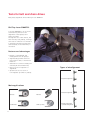
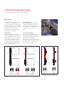
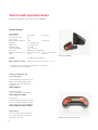
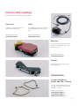
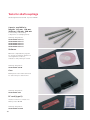
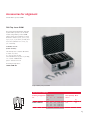
FAG-Alignment Tools
Top-Laser: SMARTY2 · TRUMMY2 · INLINE · SHIM
Technical Product Information
PT. Schaeffler Bearings Indonesia
Schaeffler (Singapore) Pte Ltd
Atrium Mulia, 2nd Floor, Suite 204
151 Lorong Chuan, #06-01
Jl. H. R. Rasuna Said Kav. B 10-11
New Tech Park, Lobby A
Jakarta - 129100
Singapore 556741
Indonesia
Phone
+65 6540 8600
Phone
+62 21 5290 7258
Fax
+65 6540 8668
Fax
+62 21 5290 7260
E-mail
marketing_sg@schaeffler.com
E-mail
marketing_id@schaeffler.com
MATNR 000000000-0000 / TPI 182 / GB-SG/MY/TH/PH/VN/ID / 2008100.5 / Printed in Germany by Weppert
Schaeffler Thailand Co., Ltd
Schaeffler Bearings (Malaysia) Sdn Bhd.
388 Exchange Tower
5-2 Wisma Fiamma
34th Fl., Unit 3403–3404
No. 20 Jalan 7A/62A
Sukhumvit Rd., Klongtoey
Bandar Menjalara
Bangkok 10110
52200, Kuala Lumpur
Thailand
Malaysia
Phone
+66 2 697 0000
Phone
+60 3 6275 0620
Fax
+66 2 697 0001
Fax
+60 3 6275 6421
E-mail
marketing_th@schaeffler.com
E-mail
marketing_my@schaeffler.com
Schaeffler (Singapore) Pte Ltd
Vietnam Representative Office
225 Khanh Hoi St., Ward 3, District 4
Ho Chi Minh City
Vietnam
Phone
+84 8 9 432 860
Fax
+84 8 9 432 861
E-mail
marketing_vn@schaeffler.com
Every care has been taken to ensure the
correctness of the information contained
Schaeffler Philippines Inc
in this publication but no liability can be
5th Floor, Optima Building
accepted for any errors or omissions.
221 Salcedo Street, Legaspi Village
We reserve the right to make technical
1229 Makati City
changes.
Philippines
© Schaeffler KG · 2008, October
Phone
+63 2 759 3583
This publication or parts thereof may not
Fax
+63 2 759 3578
be reproduced without our permission.
E-mail
marketing_ph@schaeffler.com
TPI 182 GB-SG/MY/TH/PH/VN/ID
Contents
Tools for belt and chain drives
Belt pulley alignment device
FAG-Top-Laser SMARTY2
Belt tension measuring device
FAG-Top-Laser TRUMMY2
2
2
5
Tools for shaft couplings
7
Shaft alignment device FAG-Top-Laser INLINE
7
Accessories for alignment
13
Shims FAG-Top-Laser SHIM
13
Comparison of ordering designations
15
F’IS-products, services and training –
everything from a single source
16
The designation system of the INA and FAG brands has
been harmonised. This catalogue contains the new ordering
designations, which are currently only valid for Europe.
Customers outside Europe are requested to continue using
the old ordering designations
(please see the comparison on page 15).
Tools for belt and chain drives
Belt pulley alignment device FAG-Top-Laser SMARTY2
FAG-Top-Laser SMARTY2
Top-Laser SMARTY2 is an economical measuring device for the
alignment of belt pulleys and
chain sprockets.
Through the use of this device, the
wear of belts, belt pulleys, bearings
and seals is reduced. Less vibration
is generated and the running time
and reliability of the machinery is
increased.
Features and advantages
• Display of parallelism and
misalignment of both pulleys
• Significantly quicker and more
precise than other, conventional
methods
• Suitable for both horizontally and
vertically mounted machinery
• Only one person required for
alignment
• System can also be used on
non-magnetic sprockets or pulleys.
Alignment of belt pulleys
Types of misalignment
Angular misalignment
Main applications
Parallel misalignment
2
Flat belts
Vee belts
Toothed belts
Chain sprockets
Angular misalignment
+ parallel misalignment
Tools for belt and chain drives
Belt pulley alignment device FAG-Top-Laser SMARTY2
Easy to use
The FAG-Top-Laser SMARTY2 can be
mounted in just a few seconds.
The laser beam can be clearly seen
on the target marks. Once the laser
beam is adjusted to coincide with
the slots in the target marks,
the machine is correctly aligned.
Nothing could be simpler.
Aluminium pulleys
Since the measuring instrument is
so light, the emitter and target
marks can be easily attached to
non-magnetic drive pulleys using a
strong, double-sided adhesive
tape.
Target marks
The target marks are available in
optical and digital form. In the case
of the digital target mark, adjustment values are shown in real time
in the display. Angular misalignments are presented in degrees
and the parallelism offset in mm.
This allows simple documentation
of the alignment process.
Laser beam adjustment
The laser beam emitted by the
measuring instrument is adjusted
parallel to the magnetic holders of
the measuring instrument.
If a deviation is found, this can be
checked locally on a flat surface by
the op erator and readjustment
carried out if necessary.
A
A
B
B
A
B
Not precisely aligned
A
B
Precisely aligned
FAG-Top-Laser SMARTY2 in operation
For drives with pulleys of different widths, the
marks should be moved within the target marks
Alignment example using a belt drive
3
Tools for belt and chain drives
Belt pulley alignment device FAG-Top-Laser SMARTY2
Technical data
Laser emitter
Belt pulleys
Laser beam angle
Laser class
Measurement distance
Batteries
Battery life
Output power
Laser wavelength
Housings
Dimensions W ~ H ~ D
Mass
≥ 60 mm ø
≥ 2,36 in ø
78°
2
10 m
32,81 feet
1 ~ R6 (AA) 1,5 V
8 h continuous
< 1 mW
635...670 nm
ABS plastic, aluminium
145 ~ 86 ~ 30 mm 5,71 ~ 3,39 ~ 1,18 in
270 g
0,59 lbs
Targets
2 magnetic target marks
Measurement accuracy
better than 0,5 mm / 0,02 in or 0,2° *)
FAG-Top-Laser SMARTY2
*) General rule for deviations (depending on belt type):
less than 0,25° [4,4 mm/m]
Ordering designation and
scope of delivery:
Laser measuring instrument, complete, including 2 target marks,
2 batteries and user manual in
padded case:
LASER-SMARTY2
Replacement part:
1 optical magnetic target mark
LASER-SMARTY2.TARGET
Accessories:
1 digital magnetic target mark incl.
1 case for digital magnetic target
mark and FAG-Top-Laser SMARTY2
LASER-SMARTY2.TARGET-DIGITAL
Safety advice
Do not look into the laser beam.
Do not point the laser beam into
other persons’ eyes.
4
Digital magnetic target mark (accessory)
Tools for belt and chain drives
Belt tension measuring device FAG-Top-Laser TRUMMY2
FAG-Top-Laser TRUMMY2
Easy to use
The robust, handy Top-Laser
TRUMMY2 is an optical-electronic
instrument for measuring and
setting optimum belt tension
(strand force). Through the use of
this device, the maximum output
and and optimum life of belt
drives, bearings and seals can be
achieved.
The user-friendly Top-Laser TRUMMY2
can be used in many locations and
comprises a cableless measurement probe, a measurement probe
with cable for difficult to access
locations and a microprocessor
that indicates relevant measurables
for belt tension either as frequency
[Hz] or force [N]. By means of an
impulse (for example by striking
the stationary belt), the tensioned
belt is excited to natural vibration.
The individual static natural
frequency thus generated is
measured within seconds by the
TRUMMY2 sensor using clock pulse
light and displayed. In order to
calculate the strand force of the
belt drive, the belt mass and length
are entered in the microcomputer
before measurement. TRUMMY2
uses these to calculate the strand
force, which is then compared with
the specified nominal value.
Features and advantages
• Maximum life of belt drives can
be ensured
• Reduced wear of drive components
• Reduced energy costs and
in creased cost-efficiency
• Absolutely reliable results due
to new measurement method
(clock pulse light)
• Simple and easy to use
• Multilingual operator interface.
Measurement using cableless measurement probe
5
Tools for belt and chain drives
Belt tension measuring device FAG-Top-Laser TRUMMY2
Technical data
Measurement range
Digital sampling error
Total error
Operating temperature
Housing
Device dimensions
Mass
Display
Input limits
Free strand length
Belt mass
Power supply
10 Hz to 800 Hz
< 1%
< 5%
+10 °C to +50 °C
50 to 122 °F
ABS plastic
80 ~ 126 ~ 37 mm
3,15 ~ 4,96 ~ 1,46 in
300 g
2 lines LCD, 16 characters
up to 9,990 m
up to 9,999 kg/m
9 Volt battery
up to 32,7752 feet
up to 6,7190 lbs/feet
Ordering designation and scope of delivery:
Laser measuring device in plastic case
incl. 1 cableless measurement probe and 1 measurement probe with cable:
LASER-TRUMMY2
FAG-Top-Laser TRUMMY2
6
Tools for shaft couplings
Shaft alignment device FAG-Top-Laser INLINE
Application
FAG-Top-Laser INLINE
More than half of all unplanned
machine downtime can be attributed
to misalignment and imbalance.
These problems can also arise in the
use of flexible couplings.
The FAG-Top-Laser INLINE is a
PC-based system for aligning
coupled shafts which can be used
to significantly increase the
availability of machinery.
The FAG-Top-Laser INLINE is suitable for aligning coupled shafts in
motors, pumps, ventilators and
gearboxes (with rolling bearings).
Features and advantages
• Simple to mount
• Error-free handling even by
untrained personnel due to
automatic measurement and
pos itioning process
• More precise alignment than with
conventional methods
(dial gauge and straight edge)
• Rapid measurement by “Continuous Sweep” (continuous rotary
motion/patented method);
70° rotary motion is adequate
for measurement (any position
and rotary motion)
• Optimised measurement by
“Single Beam Technology”
(double laser travel distance
through reflection)
• Reduced vibration and friction
losses
• Increased productivity through
longer machine running times
• Significantly lower energy
consumption
• Suitable for use with standard
laptop via PCMCIA interface.
FAG-Top-Laser INLINE in operation
PC card
Case
Software
Reflector
Cable
Post
Chain
Scope of delivery of FAG-Top-Laser INLINE
Bracket
Transceiver
Scope of delivery:
1 transceiver (incl. 3 m cable)
1 reflector
2 brackets
2 chains (300 mm)
4 posts (115 mm)
1 software (manual, help CD)
1 case
1 serial PC card
Ordering designation:
Complete FAG Top-Laser INLINE:
LASER-INLINE
7
Tools for shaft couplings
Shaft alignment device FAG-Top-Laser INLINE
Actions before alignment
Before any alignment operation,
any tilting foot (machine foot that
lifts off the floor when slackened)
should be removed in order to prevent increased vibration tendency
and bearing damage due to housing
distortion.
The Top-Laser INLINE helps to
quickly identify and eliminate the
so-called soft foot. It is only
necessary to loosen each individual
screw foot connection. The computer
determines any foot movement.
The foot tilt can then be eliminated
using shims (see page 13).
Accessories
Accessories for
FAG-Top-Laser INLINE
Scope of
delivery
Ordering designation
Chain, 600 mm long
Chain, 1500 mm long
2 pieces
2 pieces
LASER-INLINE.CHAIN600
LASER-INLINE.CHAIN1500
Post,
Post,
Post,
Post,
4
4
4
4
LASER-INLINE.POST150
LASER-INLINE.POST200
LASER-INLINE.POST250
LASER-INLINE.POST300
150
200
250
300
mm
mm
mm
mm
long
long
long
long
pieces
pieces
pieces
pieces
Magnetic holders
1 piece
LASER-INLINE.MAGNET
Accessory case, empty
1 piece
LASER-INLINE.CASE-ACCESSORIES
Accessory set, complete
1 piece
LASER-INLINE.ACCESS-SET
This contains all of the items
listed above with the exception
of the four posts, 150 mm long
Chains
For mounting of brackets on shafts
• 600 mm long for
max. shaft diameter of 200 mm
• 1500 mm long for
max. shaft diameter of 500 mm
Software with soft foot
Accessories
The possible applications of the
LASER-INLINE basic device can be
expanded with the aid of a comprehensive range of accessories.
The accessories can be ordered as
a set in a handy, robust case or –
individually compiled –
as individ ual parts.
8
Posts
For mounting of measuring
com ponents on clamping device
• 150 mm long
• 200 mm long
• 250 mm long
• 300 mm long
Magnetic holders
For rapid mounting and fine adjustment of measuring components on
narrow coupling flanges
Tools for shaft couplings
Shaft alignment device FAG-Top-Laser INLINE
Transceiver
Cable
Compact, robust transceiver for
visible laser beam (red)
For supplying power to transceiver
and exchanging data with control
unit
Ordering designation:
LASER-INLINE.TRANS
Ordering designation:
LASER-INLINE.CABLE
Cable
Transceiver
Reflector
Roof prism with compact housing,
mounted on clamping device by
means of lever
Ordering designation:
LASER-INLINE.REFLECT
Bracket
Basic element of compact chain
clamping device
Ordering designation:
LASER-INLINE.BRACKET
2 chains, available in
lengths 300, 600, 1500 mm
For max. shaft diameters 100 mm,
200 mm, 500 mm for mounting of
brackets on shafts
Ordering designations:
LASER-INLINE.CHAIN300
LASER-INLINE.CHAIN600
LASER-INLINE.CHAIN1500
9
Tools for shaft couplings
Shaft alignment device-FAG Top-Laser INLINE
4 posts, available in
lengths 115 mm, 150 mm,
200 mm, 250 mm, 300 mm
For mounting of measuring
com ponents on clamping device
Ordering designations:
LASER-INLINE.POST115
LASER-INLINE.POST150
LASER-INLINE.POST200
LASER-INLINE.POST250
LASER-INLINE.POST300
Software
Windows-compatible PC program
for storage of machine dimensions
and alignment conditions,
evaluation and printing of results
Ordering designation:
LASER-INLINE.SOFTW
Case
Black plastic case with foam insert
for safe transport of the device
Ordering designation:
LASER-INLINE.CASE
PC card (type II)
Insertion in PC for connection to
FAG-Top-Laser INLINE
Ordering designation:
LASER-INLINE.PCCARD
10
Tools for shaft couplings
Shaft alignment device FAG-Top-Laser INLINE
Easy to use
Before alignment, eliminate any foot tilt (see page 8).
Mount the chain clamping device at the same angle on
both sides of the shaft coupling.
Mount the transceiver on the side of the shaft coupling
defined as stationary (pump, ventilator).
Mount the reflector on the side of the shaft coupling
defined as movable (motor).
Connect the transceiver to the PC card, insert the card
in the laptop. The FAG-Top-Laser INLINE software will
start.
DIM – Enter three machine dimensions, see example
“Input data for coupling”.
Input data for coupling
M – Enter position of transceiver and reflector relative
to the coupling.
The laser beam is centred on the screen in accordance
with the instructions, see example “Scan”.
The deviations in the horizontal and vertical directions
are measured by rotating the coupled shaft by at least
70° (in any direction).
Scan
ERG – The result is given as the amounts in mm (inch),
by which the front or rear foot must be adjusted up or
down (by inserting or removing the shims Top-Laser
SHIM, see page 13). For horizontal alignment, the feet
are moved (see animation).
Finally, correct alignment is checked by means of a
verification measurement.
Measurement results
11
Tools for shaft couplings
Shaft alignment device FAG-Top-Laser INLINE
Technical data
Transceiver
Measurement method:
Protection class:
Protection against ambient light:
Storage:
Operation:
Dimensions (W ~ H ~ D):
Mass:
coaxial, reflected laser beam
IP67 (dustproof, water proof under temporary immersion)
yes
–20 to +80 °C
–4 to +176 °F
0 to 55 °C
32 to 131 °F
approx. 107 ~ 70 ~ 49 mm
approx. 4,213 ~ 2,756 ~ 1,929 in
approx. 177 g
approx. 0,39 lbs
Laser (Ga-Al-As semiconductor laser)
Wavelength (typical):
Laser class:
Beam power:
Interface:
Max. recommended distance:
670 nm (red, visible)
2; FDA 21CFR 1000 & 1040
< 1 mW
Serial I/0 PCMCIA card, type II
3m
9,84 feet
Detector
Measurement range:
Resolution:
Accuracy:
± 4 mm
1 μm
better than 2 %
± 0,157 in
Inclinometer
Measurement range:
Resolution:
0 to 360°
less than 1°
Reflector
Type:
Protection class:
Accuracy:
Storage:
Operation:
Dimensions (W ~ H ~ D):
Mass:
90° roof prism
IP67 (dustproof, waterproof under temporary immersion)
better than 1 %
–20 to +80 °C
–4 to +176 °F
–20 to +60 °C
–4 to +140 °F
approx. 100 ~ 41 ~ 35 mm
approx. 3,937 ~ 1,614 ~ 1,378 in
approx. 65 g
approx. 0,143 lbs
Carry case
Material:
Dimensions (W ~ H ~ D):
Mass with standard components:
standard ABS, black, drop tested (2 m)
approx. 470 ~ 400 ~ 195 mm
approx. 6,8 kg
approx. 18,503 ~ 15,748 ~ 7,677 in
approx. 15 lbs
Range of application
Shaft diameter:
12
min. 12 mm, max. 500 mm (with accessories) min. 0,472 in, max. 19,685 in
Accessories for alignment
Shims FAG-Top-Laser SHIM
FAG-Top-Laser SHIM
Any vertical misalignment detected
by the FAG-Top-Laser can be elim inated using FAG-Top-Laser SHIM.
These shims are available in seven
thickness values (0,05; 0,10; 0,20;
0,50; 0,70; 1,00 and 2,00 mm) and
four sizes (dimension C = 15, 23,
32 or 44 mm).
Contents of a set
(basic version):
The handy case contains 20 shims
in each of 3 sizes
C = 15, 23 and 32 mm
and 6 thicknesses (0,05 to 1,00 mm),
i.e. a total of 360 shims
plus 1 extraction hook
Ordering designation:
LASER.SHIM-SET
Scope of delivery of Top-Laser SHIM
FAG-Top-Laser SHIM Set
Ordering designation Dimensions
Set
A
B
C
mm
Thickness
Total quantity Mass
Shims
kg
A
LASER.SHIM-SET
C
55
75
90
50
70
80
15
23
32
0,05–1,0
0,05–1,0
0,05–1,0
360
6,7
B
13
Accessories for alignment
Shims FAG-Top-Laser SHIM
Individual or spare parts
As individual or spare parts, we
supply 10 shims each in one of the
four sizes stated above
(dimension C = 15, 23, 32 or 44 mm)
and one of the seven thicknesses.
Ordering examples:
• 10 shims each of dimension
C = 15 mm and 0,20 mm thickness:
LASER.SHIM15X0,20
• 10 shims each of dimension
C = 44 mm and 0,10 mm thickness:
LASER.SHIM44X0,10
• 10 shims each of dimension
C = 23 mm and 2,00 mm thickness:
LASER.SHIM23X2,00
A
C
B
14
Individual parts and spare parts for FAG-Top-Laser SHIM
Ordering designation
FAG
Dimensions
A
B
C
mm
Thickness
Number of Mass
shims
g
LASER.SHIM15X0,05
LASER.SHIM15X0,10
LASER.SHIM15X0,20
LASER.SHIM15X0,50
LASER.SHIM15X0,70
LASER.SHIM15X1,00
LASER.SHIM15X2,00
55
55
55
55
55
55
55
50
50
50
50
50
50
50
15
15
15
15
15
15
15
0,05
0,10
0,20
0,50
0,70
1,00
2,00
10
10
10
10
10
10
10
11
22
44
110
155
220
440
LASER.SHIM23X0,05
LASER.SHIM23X0,10
LASER.SHIM23X0,20
LASER.SHIM23X0,50
LASER.SHIM23X0,70
LASER.SHIM23X1,00
LASER.SHIM23X2,00
75
75
75
75
75
75
75
70
70
70
70
70
70
70
23
23
23
23
23
23
23
0,05
0,10
0,20
0,50
0,70
1,00
2,00
10
10
10
10
10
10
10
21
42
84
210
295
420
840
LASER.SHIM32X0,05
LASER.SHIM32X0,10
LASER.SHIM32X0,20
LASER.SHIM32X0,50
LASER.SHIM32X0,70
LASER.SHIM32X1,00
LASER.SHIM32X2,00
90
90
90
90
90
90
90
80
80
80
80
80
80
80
32
32
32
32
32
32
32
0,05
0,10
0,20
0,50
0,70
1,00
2,00
10
10
10
10
10
10
10
29
58
115
290
410
580
1160
LASER.SHIM44X0,05
LASER.SHIM44X0,10
LASER.SHIM44X0,20
LASER.SHIM44X0,50
LASER.SHIM44X0,70
LASER.SHIM44X1,00
LASER.SHIM44X2,00
125
125
125
125
125
125
125
105
105
105
105
105
105
105
44
44
44
44
44
44
44
0,05
0,10
0,20
0,50
0,70
1,00
2,00
10
10
10
10
10
10
10
53
105
210
530
740
1050
2100
Comparison of ordering designations
Ordering designation for Europe
Ordering designation for countries outside Europe
LASER-INLINE
LASER-INLINE.ACCESS-SET
LASER-INLINE.BRACKET
LASER-INLINE.CABLE
LASER-INLINE.CASE
LASER-INLINE.CASE-ACCESSORIES
LASER-INLINE.CHAIN300 (~600; ~1500)
LASER-INLINE.MAGNET
LASER-INLINE.PCCARD
LASER-INLINE.POST115 (~150; ~200; ~250; ~300)
LASER-INLINE.REFLECT
LASER-INLINE.SOFTW
LASER-INLINE.TRANS
LASER.INLINE
LASER.INLINE.ACCESS.SET
LASER.INLINE.BRACKET
LASER.INLINE.CABLE
LASER.INLINE.SUITCASE
LASER.INLINE.ACCESS.SUITCASE
LASER.INLINE.CHAIN300 (~600; ~1500)
LASER.INLINE.MAGNET
LASER.INLINE.PCCARD
LASER.INLINE.POST115 (~150; ~200; ~250; ~300)
LASER.INLINE.REFL
LASER.INLINE.SOFTWARE
LASER.INLINE.TRANS
LASER.SHIM-SET
LASER.SHIM15X0,05
LASER.SHIM23X0,05
LASER.SHIM32X0,05
LASER.SHIM44X0,05
LASER.SHIMS.SET
LASER.SHIMS15.0,05
LASER.SHIMS23.0,05
LASER.SHIMS32.0,05
LASER.SHIMS44.0,05
(~0,10;
(~0,10;
(~0,10;
(~0,10;
~0,20
~0,20
~0,20
~0,20
...
...
...
...
~2,00)
~2,00)
~2,00)
~2,00)
(~0,10;
(~0,10;
(~0,10;
(~0,10;
~0,20
~0,20
~0,20
~0,20
LASER-SMARTY2
LASER-SMARTY2.TARGET
LASER-SMARTY2.TARGET-DIGITAL
LASER.SMARTY2
LASER.SMARTY2.TARGET
LASER.SMARTY2.TARGET.DIGITAL
LASER-TRUMMY2
LASER.TRUMMY2
...
...
...
...
~2,00)
~2,00)
~2,00)
~2,00)
15
F’IS products, services and training –
everything from a single source
FAG Industrial Services (F’IS) is a
full service supplier in the field of
condition-based maintenance.
With the sourcing of high quality
F’IS products, the customer thus
gains access to a range of productoriented services relating to rolling
bearings: from mounting, through
maintenance to reconditioning of
rolling bearings (see diagram).
In the field of alignment, F’IS offers
not only service products but also
professional alignment as a service.
Where necessary, the F’IS service
technician will take the necessary
laser alignment system to the
customer and carry out alignment
of the machine in accordance with
the manufacturer’s specifications.
Successful completion of the work
is then documented.
Rolling bearing
technology /
design
Reconditioning of
rolling bearings
Materials,
coatings
On the basis of product presentations, we will be pleased to
instruct our customers where
necessary in the use and handling
of alignment devices so that they
are then in a position to carry out
such alignment work themselves.
If you have any further questions
on our services, please contact us
direct or visit our website.
Tribology
Services relating to
rolling bearings
Corrective
maintenance
Mounting
Lubrication
• Balancing
• Alignment
Condition monitoring
• Online and offline
measurement
• E-service
• Thermography
• Modal analysis
• etc.
Technical
consultancy
16
Customer training
MATNR 035582600-0000 / TPI 182 / GB-D / 2008102 / Printed in Germany by Weppert
Every care has been taken to ensure the
correctness of the information contained
Schaeffler KG
Postfach 1260
97421 Schweinfurt (Germany)
Georg-Schäfer-Strasse 30
97421 Schweinfurt (Germany)
Phone
Fax
+49 2407 9149-66
+49 2407 9149-59
E-Mail info@fis-services.com
Internet www.fis-services.com
in this publication but no liability can be
accepted for any errors or omissions.
We reserve the right to make technical
changes.
© Schaeffler KG · 2008, October
This publication or parts thereof may not
be reproduced without our permission.
TPI 182 GB-D