1
PC User's Manual
ASC Incorporated
Computerized
Diagnostic System:
System Diagnostics
Software Installation
Auto-configuration
MITSUBISHI 3000GT
Table of Contents
Introduction ........................................................................................................... 3
Connections and Startup ...................................................................................... 4
Run Diagnostics Program ..................................................................................... 8
View DTC Log ..................................................................................................... 12
Begin Auto-configuration..................................................................................... 13
Appendix A: Diagnostic Trouble Codes ............................................................. 23
Appendix B: Change Default Parameters .......................................................... 29
Appendix C: Software Installation ...................................................................... 34
Appendix D: Hardware Installation ..................................................................... 36
Appendix E: Connecting to the Spyder ECU connector ..................................... 44
Appendix F: Evoscan Support ........................................................................... 48
Table of Tables
Table 1 – DTC Codes 00 through 13 .................................................................. 23
Table 2 – DTC Codes 14 through 25 .................................................................. 24
Table 3 – DTC Codes 26 through 36 .................................................................. 25
Table 4 – DTC Codes 37 through 48 .................................................................. 26
Table 5 – DTC Codes 49 through 58 .................................................................. 27
Table 6 – DTC Codes 59 through 62 .................................................................. 28
Table 7 - Hardtop ECU Default Parameters........................................................ 32
Table of Figures
Figure 1 – PC to ECU Hookup .............................................................................. 4
Figure 2 - Top_Link Converter Module ............................................................... 36
Figure 3 - USB A/B Cable ................................................................................... 36
Figure 4 - Cable "A" ............................................................................................ 44
Figure 5 - Cable "B" ............................................................................................ 44
Figure 6 - Spyder DLC location ........................................................................... 45
Figure 7 - Toplink Cable “A” Drawing .................................................................. 46
Figure 8 - Toplink Cable "B" Drawing.................................................................. 47
Figure 9 - OBD II Cable Drawing ........................................................................ 48
Figure 10 - OBDII Cable ..................................................................................... 48
PC USER'S MANUAL
JNS Engineering
- ASC Incorporated Computerized Diagnostic System
2
3/13/2010
Introduction
This PC User's Manual is for the Mitsubishi 3000GT Spyder. This manual should
be used in conjunction with the Service Manual Supplement (Volume 3) when
servicing or re-pairing the vehicle.
There are specific instructions and cautions that appear in the Service Manual
Supplement that should be strictly adhered to. Otherwise, personal injury or
damage to the vehicle could result.
Caution:
Mechanical adjustments to, or replacement of components of the
retractable hardtop system, with the exception of hard and soft trim, will
require that the hardtop ECU be run through "auto-configuration" using the
ASC INCORPORATED computerized diagnostic system. When applicable
DO NOT perform any adjustment or replacement of those retractable
hardtop components without having the latest version of the ASC
INCORPORATED diagnostic system.
The Spyder hardtop ECU includes control of 3.5 retractable hardtop axes:
hardtop, hard tonneau, tonneau latch/unlatch, and header latch/unlatch.
The hardtop ECU also controls the three vehicle window systems: passenger
door window, driver door window, and retractable quarter window system.
PC USER'S MANUAL
JNS Engineering
- ASC Incorporated Computerized Diagnostic System
3
3/13/2010
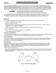
Connections and Startup
1.
Connect the PC to the ECU
Figure 1 – PC to ECU Hookup
Connect the components as shown in the illustration above. The ECU
connector in the vehicle is located behind the carpet at the base of the
cowl near the floor.
2.
Connect a 12V battery charger to the vehicle battery to maintain battery
voltage. Use slow charging of 5 - 10 amps.
Caution:
When batteries are being charged, an explosive gas forms beneath
the cover of each cell. Do not smoke near batteries on charge or
which have been recently charged. Do not break live circuits at the
terminals of the batteries on charge. A spark will occur where the live
circuit is broken. Keep all open flames away from the battery.
Battery electrolyte temperature may temporarily be allowed to rise to 55/C
(131/F). Increase of electrolyte temperature above 55 /C (131/F) is
PC USER'S MANUAL
JNS Engineering
- ASC Incorporated Computerized Diagnostic System
4
3/13/2010
harmful to the battery, causing deformation of battery cell, decrease in life
of the battery, etc.
3.
Turn the ignition switch to the ON position.
4.
Wake up the ECU from sleep mode.
The hardtop ECU must be awakened from its sleep mode for the PC to
communicate with it. The hardtop ECU will immediately go to sleep after
the hardtop has been fully closed or fully opened. Awakening the ECU can
be performed several ways:
NOTE:
The ECU should be awake if the hardtop or tonneau is not fully open or
closed.
With the hardtop fully open or closed, press and hold the passenger
window switch to keep the ECU awake, or;
Momentarily press the hardtop "OPEN" switch (if the hardtop is
closed) or "CLOSE" switch (if the hardtop is open) until the chime
and indicator are active.
5.
Double Click the ASC Icon to start the program
You will see the opening screen shown below:
6.
Press {ENTER} to begin the program.
PC USER'S MANUAL
JNS Engineering
- ASC Incorporated Computerized Diagnostic System
5
3/13/2010
7.
After {ENTER} is pressed the DIAGNOSTICS MAIN MENU will appear.
Use the up (↑) or down (↓) arrow keys to highlight the desired selection
from the menu. Then press {ENTER} to make your selection.
To end the program, either highlight the “EXIT” selection and press
{ENTER}, or press the {Esc} key.
NOTE: If you get a screen with a blank box, you have not established
communication with the ECU. Check all connections then repeat Steps 36.
PC USER'S MANUAL
JNS Engineering
- ASC Incorporated Computerized Diagnostic System
6
3/13/2010
The program automatically starts up in fullscreen mode. At any time you can
change the display to a smaller window using {ALT} {ENTER}. When this is
done you will see that DOSBox maintains two windows for the application – the
program window and the status window. The status window normally looks like
this screenshot. The serial mode errors are normal and have no effect on proper
program operation.
COM1 must be available for the program to work properly; otherwise the
following error will appear.
If COM1 is not available refer to Appendix D, Software Installation.
PC USER'S MANUAL
JNS Engineering
- ASC Incorporated Computerized Diagnostic System
7
3/13/2010
Run Diagnostics Program
1.
To view the diagnostics screen use the up (↑) or down (↓) arrow keys to
highlight the “Run Diagnostics Program” selection from the Main Menu.
Press {ENTER} to make your selection. You will see the screen below.
NOTE: If at anytime you want to escape to the Main Menu press
{Esc}, then choose Y or N.
2.
This run diagnostics screen shows the data the ECU has collected since it
left the factory or since it was last replaced. It also shows current status of
general ECU inputs and outputs. The screen will constantly update the
data as the system is being operated.
3.
For continuous updates to the axis position display, make sure the Loop
Mode is ON by pressing the L key so that Loop ON appears in the top
left corner of the display.
4.
To return to the Position Display mode from any other mode press the P
key.
PC USER'S MANUAL
JNS Engineering
- ASC Incorporated Computerized Diagnostic System
8
3/13/2010
Clearing the DTC log, if desired.
1.
Press the U key to ask to clear the DTC log.
2.
You will be prompted whether you want to clear the log. Press Y if
you want to clear the log; the PC will automatically send all the
necessary commands to the ECU. Press N if you decide not to
clear the DTC log.
NOTE:
If you decide to clear the DTC Log, record the DTCs for future reference
before clearing the log.
Screen legends
Hardtop Switch: Changes from " . . . ." to OPEN or CLOSE when the
hardtop "OPEN"/"CLOSE" switch is pressed.
Tonneau Switch: Changes from ". . . ." to UP or DOWN when the
tonneau "OPEN"/"CLOSE" switch is pressed.
Header Latch/Unlatch: Changes from CLOS to OPEN depending on the
status of the switches. The words Latch or Unlatch will be highlighted to
show the header latch state inside the ECU.
Header Position LH/RH: Changes from CLOS to OPEN depending on
the status of the switches. The switches should register CLOS if the
hardtop is fully closed.
Tonneau Unlatch Left/Right: Changes from CLOS to OPEN depending
on the status of the switches. The switches should register CLOS when
the tonneau is fully closed.
Driver Window Switch: The PC does not display the driver window
switch status.
Passenger Window Switch: Changes from " . . . . " to OPEN or CLOSE
when the Passenger Window Switch is pressed.
Q Window Retracted/Extended: Changes from CLOS to OPEN
depending on the status of the position sensors. The Extended sensor
should show CLOS and the Retracted sensor should show OPEN when
the quarter windows are fully extended (closed). The Retracted sensor
should show CLOS and the Extended sensor should show OPEN when
the quarter windows are fully retracted (open).
Hardtop Motor (hydraulic pump/motor): Changes from ". . . ." to
CLOSE or OPEN when the pump motor is ON.
Tonneau Motor (hydraulic pump/motor): Changes from ". . . ." to
OPEN or CLOSE when the pump motor is ON.
PC USER'S MANUAL
JNS Engineering
- ASC Incorporated Computerized Diagnostic System
9
3/13/2010
Header Latch Motor: Changes from ". . . ." to UP or DOWN when the
motor is ON.
Tonneau Unlatch Motors: Changes from ". . . ." to ON when the motor is
ON.
Driver Window Motor: The PC displays the driver window motor status
only when operated through the hardtop switch.
Passenger Window Motor: Changes from ". . . ." to UP or DOWN when
the motor is ON.
Quarter Window Motor: Changes from ". . . ." to CLOS or OPEN when
the motor is ON.
Pot (Potentiometer) Readings (Min Pos Max): The center section of
the screen shows the measured values of the potentiometer for each axis.
Values are in decimal notation, 0 to 255. The Min value is the low limit for
that axis. The Max value is the high limit for that axis. The Header Latch
entry is a “simulated” axis, and does not reflect a reading from an actual
potentiometer.
Battery Voltage: Battery voltage as measured by the ECU
(approximate). The ECU will not operate if this voltage is below 10V and
above 16V. Hardtop operation becomes very sluggish when the voltage
drops below 11V.
Switch Reference: Switch reference voltage as measured by the ECU
(approximate). This voltage should be 1.3 - 1.7 volts at all times.
Pot (Potentiometer) Feed : Pot feed voltage as measured by the ECU
(approximate). This voltage should be 4.8 - 5.2 volts at all times.
Hardware Version: The hardware revision number reported by the ECU.
Software Version: The software revision number reported by the ECU.
Wheel Speed: Indicates vehicle speed as sensed by the ECU from a
pulse train received from an ABS wheel speed sensor. Yes means you
have wheel speed and the vehicle is moving too fast; the ECU will not
allow the hardtop to move. No means the vehicle is stationary or moving
slowly enough to allow the hardtop to move.
Parking Switch Input: Status of the automatic transmission. PARK
means that the transmission is in Park and the ECU will allow the top to
move. GEAR means that the vehicle is in gear and the ECU will not allow
the top to move.
Parking Brake: Status of the parking brake. YES means that the parking
brake is applied and the ECU will allow the top to move. NO means that
the parking brake is not applied and the ECU will not allow the top to
move. NOTE: This applies only to vehicles with manual transmission.
PC USER'S MANUAL
JNS Engineering
- ASC Incorporated Computerized Diagnostic System
10
3/13/2010
Object(-In-Trunk) Sensor Connected: Indicates YES if the Object-InTrunk Sensor (OTS) is connected, NO if it is not connected. The ECU will
not allow the hardtop to go into the cargo/hardtop stowage area if the OTS
is not connected.
Object In Trunk: Indicates YES if the OTS registers an object in the
cargo/hardtop stowage area, NO if there is no object in there. The ECU
will not allow the hardtop to go into the cargo/hardtop stowage area if the
OTS registers an object in there.
Cycle Count: Number of complete hardtop system cycles (full close-tofull open-to-full close = one complete cycle) since the vehicle left the
factory or since the ECU was last replaced.
DTC Log: Indicates the status of the DTCs and displays up to 5 entries.
The first number is the entry number (1-5). The second number is the
DTC. The third number is the number of times this error has been logged.
If the fault is active, the DTC is highlighted.
5.
Press M to access the Motor Motion section of the diagnostic program.
The password is CHERRY (as we know now that the Top ECU was
subcontracted by ASC to Cherry Electric).
Use the up (↑) or down (↓) arrow keys to select the motor(s) to control and then
hit the {ENTER} to make your selection (the selected motor(s) will have *….*
highlighted. Then use the Top Open/Close switch in the car to actuate the
motor(s). When finished with motor motion press {Esc} or P to return to the
Position Display.
PC USER'S MANUAL
JNS Engineering
- ASC Incorporated Computerized Diagnostic System
11
3/13/2010
View DTC Log
1.
Use the up (↑) or down (↓) arrow key to highlight “View DTC Log” on the
Main Menu and press {ENTER}. You will see a screen similar to the
figure below:
2.
If there are active DTC faults (those with YES in the ACTIVE column),
correct these conditions and clear the DTC log before proceeding with
auto-configuration. Press any key to return to the Main Menu.
3.
For complete descriptions of the DTCs, refer to the Service Manual
Supplement (Volume 3) or see Appendix A.
PC USER'S MANUAL
JNS Engineering
- ASC Incorporated Computerized Diagnostic System
12
3/13/2010
Begin Auto-configuration
Auto-configuration consists of moving each axis, one at a time and automatically
changing and recording the end limits.
1.
Press the up (↑) or down (↓)
arrow to highlight “Begin Auto
Configuration” on the Main Menu. Press {ENTER} to make this
selection.
The PC will begin by setting up a number of parameters in the ECU. This
may take several seconds. You will then see the warning screen below.
2.
Press {ENTER} to continue with auto-configuration.
NOTE: You may return to the Main Menu at any time during autoconfiguration by pressing the {Esc} key.
PC USER'S MANUAL
JNS Engineering
- ASC Incorporated Computerized Diagnostic System
13
3/13/2010
3.
The PC will prompt you to Press Hardtop OPEN Switch. The door and
quarter windows will begin to open. Hold the switch until you receive a
prompt to Release Hardtop OPEN Switch. When the switch is released
the following screen will appear.
NOTE: If the windows are not fully retracted and N has been pressed, press and
hold the hardtop OPEN switch again. If the windows are now fully retracted,
press Y to continue. If the windows are still not fully retracted, press A to, abort
auto-configuration.
Diagnose and repair the problem and begin autoconfiguration again.
PC USER'S MANUAL
JNS Engineering
- ASC Incorporated Computerized Diagnostic System
14
3/13/2010
4.
When Step 3 is complete and Y has been pressed the PC will prompt you
to Press Hardtop OPEN Switch. The hard tonneau will unlatch and begin
to open. Hold the switch until a prompt is received to Release Hardtop
OPEN Switch. When the switch is released the following screen will
appear.
NOTE: If the tonneau is not fully open and N has been pressed, press and hold
the hardtop OPEN switch again. If the tonneau is now fully open, press Y and
continue. If the tonneau is still not fully open, press A to abort auto-configuration.
Diagnose and repair the problem and begin auto-configuration again.
PC USER'S MANUAL
JNS Engineering
- ASC Incorporated Computerized Diagnostic System
15
3/13/2010
5.
When Step 4 is complete and Y has been pressed the PC will prompt you
to Press Hardtop OPEN Switch. The header latches will unlatch. Hold
the switch until a pompt is received to Release Hardtop OPEN Switch.
When the switch is released the following screen will appear.
NOTE: If the header is not fully unlatched and N has been pressed, press and
hold the hardtop OPEN switch again. If the header is now unlatched, press Y
and continue. If the header is still not unlatched press A to abort autoconfiguration. Diagnose and repair the problem and begin auto-configuration
again.
PC USER'S MANUAL
JNS Engineering
- ASC Incorporated Computerized Diagnostic System
16
3/13/2010
6. When Step 5 is complete and Y has been pressed the PC will prompt you
to Press Hardtop OPEN Switch. The hardtop will move to its fully open
position. Hold the switch until a prompt is received to Release Hardtop
OPEN Switch. When the switch is released the following screen will
appear.
NOTE: If the hardtop is not fully open and N has been pressed, press and hold
the hardtop OPEN switch again. If the hardtop is now fully open, press Y and
continue. If the hardtop is still not fully open press A to abort auto-configuration.
Diagnose and repair the problem and begin auto-configuration again.
PC USER'S MANUAL
JNS Engineering
- ASC Incorporated Computerized Diagnostic System
17
3/13/2010
7.
When Step 6 is complete and Y has been pressed the PC will prompt you to
Press Hardtop CLOSE Switch. The hardtop will move to its fully closed
position. When the PC detects that the hardtop is in the fully closed position,
it will prompt you to Release the Hardtop CLOSE Switch.
When the switch is released the following screen will appear.
NOTE: If the hardtop is not fully closed, and N has been pressed, press and
hold the hardtop CLOSE switch again. Release the hardtop switch when the
hardtop reaches its fully closed position. If the hardtop is now fully closed press
Y and continue. If the hardtop is still not fully closed, press A to abort autoconfiguration. Diagnose and repair the problem and begin auto-configuration
again.
Caution:
During auto-configuration the safety-stop feature will be ignored when the
hardtop is being closed.
When Step 7 is complete and Y has been pressed the PC will prompt you to
Press Hardtop CLOSE Switch. The header latches will latch. The PC will detect
that the header latches are latched and will prompt you to Release Hardtop
CLOSE Switch. No screen will appear.
PC USER'S MANUAL
JNS Engineering
- ASC Incorporated Computerized Diagnostic System
18
3/13/2010
8.
The PC will prompt you to Press Hardtop CLOSE Switch. The tonneau will
begin to close. When the PC detects that the tonneau is in the fully closed
position it will prompt you to Release Hardtop CLOSE Switch.
If the PC prompts you to Release the Hardtop CLOSE Switch before the
tonneau is in its fully closed position, release the switch then press and hold the
switch again. Release the CLOSE switch when the tonneau reaches its full
closed and latched position. When the switch is released the following screen will
appear.
NOTE: If the tonneau is not fully closed, and N has been pressed, press and
hold the hardtop CLOSE switch again. Release the hardtop switch when the
tonneau reaches its fully closed position. If the tonneau is now fully closed press
Y and continue. If the tonneau is still not fully closed, press A to abort autoconfiguration. Diagnose and repair the problem and begin auto-configuration
again.
PC USER'S MANUAL
JNS Engineering
- ASC Incorporated Computerized Diagnostic System
19
3/13/2010
9.
When Step 8 is complete and Y has been pressed the PC will calculate
the final values based on the auto-configuration procedure you just
performed. You will see a screen similar to the one below which shows the
old and new ECU values.
Caution:
The following screen is only an example. Actual results will vary
vehicle to vehicle.
Review the new versus old values. The auto-configuration program has adjusted
the parameters to account for service procedures performed and system wear.
Any changes to the values in excess of 20 should be questioned and ASC Direct
Sales Technical Service Department consulted. If you remove the Safety Stop
(Appendix B Part 4) then RRSLU will change by 30 or more.
PC USER'S MANUAL
JNS Engineering
- ASC Incorporated Computerized Diagnostic System
20
3/13/2010
Errors during Auto-configuration
Time-based Error:
If an axis does not reach its end condition before a time-out period
elapses the PC will issue an error message. For instance, if the quarter
windows run past the time limit, but the PC does not see the quarter
window limit switches, you will see the message below. Press Y to try to
move the axis again. If the second attempt fails, press A to abort autoconfiguration. Diagnose and repair the problem and begin autoconfiguration again.
PC USER'S MANUAL
JNS Engineering
- ASC Incorporated Computerized Diagnostic System
21
3/13/2010
Position-based Error:
If an axis reaches its end limit but the PC finds that its position is not a
valid end limit you will see an error message like the one below. Press Y
to try to move the axis again.
If you continually encounter problems while auto-configuring an ECU,
check again to see if there are any DTCs present. If there are DTC's,
diagnose and repair the problem and begin auto-configuration again.
Widening the default range for RRLOL or other parameters MAY eliminate
position errors.
Original defaults can always be reestablished by
reinstalling the JNS-Top_Link-Installer.
If the DTC Log is clear and problems still exist, refer to the SYMPTOM
CHART for NO DIAGNOSTIC TROUBLE CODES PRESENT, Diagnostics
and Testing in the Service Manual Supplement. For convenience the
tables from the Service Manual Supplement have been included in
Appendix A.
PC USER'S MANUAL
JNS Engineering
- ASC Incorporated Computerized Diagnostic System
22
3/13/2010
Appendix A: Diagnostic Trouble Codes
Table 1 – DTC Codes 00 through 13
PC USER'S MANUAL
JNS Engineering
- ASC Incorporated Computerized Diagnostic System
23
3/13/2010
Table 2 – DTC Codes 14 through 25
PC USER'S MANUAL
JNS Engineering
- ASC Incorporated Computerized Diagnostic System
24
3/13/2010
Table 3 – DTC Codes 26 through 36
PC USER'S MANUAL
JNS Engineering
- ASC Incorporated Computerized Diagnostic System
25
3/13/2010
Table 4 – DTC Codes 37 through 48
PC USER'S MANUAL
JNS Engineering
- ASC Incorporated Computerized Diagnostic System
26
3/13/2010
Table 5 – DTC Codes 49 through 58
PC USER'S MANUAL
JNS Engineering
- ASC Incorporated Computerized Diagnostic System
27
3/13/2010
Table 6 – DTC Codes 59 through 62
PC USER'S MANUAL
JNS Engineering
- ASC Incorporated Computerized Diagnostic System
28
3/13/2010
Appendix B: Change Default Parameters
The auto-configuration program has an entry screen to change the main
operating default parameters in the PC.
1.
Changing Default Parameters in the PC
Press the up (↑) or down (↓) arrow to highlight “Change Default
Parameters” on the Main Menu. Press {ENTER} to make this selection.
The password for accessing the defaults is 3000GT.
Screen legends
RRLOL (Rear Rail* Low Limit) End Gap
The amount added to the measured hardtop low limit to get the final
hardtop low limit.
RRHIL (Rear Rail* High Limit) End Gap
The amount added to the measured hardtop high limit to get the final
hardtop high limit.
TOLOL (Tonneau Low Limit) End Gap
PC USER'S MANUAL
JNS Engineering
- ASC Incorporated Computerized Diagnostic System
29
3/13/2010
The amount subtracted from measured tonneau low limit to get the final
tonneau low limit.
TOHIL (Tonneau High Limit) End Gap
The amount subtracted from the measured tonneau high limit to get the
final tonneau high limit.
RRSLU (Rear Rail* Safety Stop Limit) Gap
The amount subtracted from the hardtop high limit to get the safety stop
limit.
RRSGAP (Rear Rail* Stall Gap)
The amount subtracted from the hardtop stall limit to detect stall in the
hardtop open and closed position.
TOSGAP (Tonneau Stall Gap)
The amount subtracted from the tonneau stall limit to detect stall in the
tonneau open and closed position.
RRLOL (Rear Rail* Low Limit) Minimum/Maximum
The boundaries for a valid hardtop high limit.
RRHIL (Rear Rail* High Limit) Minimum/Maximum
The boundaries for a valid hardtop low limit.
TOLOL (Tonneau Low Limit) Minimum/Maximum
The boundaries for a valid tonneau low limit.
TOHIL (Tonneau High Limit) Minimum/Maximum
The boundaries for a valid tonneau high limit.
*Rear Rail refers to the portion of the Spyder hardtop into which the
quarter windows retract.
Use the up (↑) or down (↓) arrow keys to select the parameter that you
want to change. Enter a new number and press {ENTER}. Press
{Control}-{ENTER} to save the new values and return to the Main Menu.
PC USER'S MANUAL
JNS Engineering
- ASC Incorporated Computerized Diagnostic System
30
3/13/2010
2.
Changing default parameters in the hardtop ECU.
(1)
Viewing and modifying the ECU parameters.
Key ECU parameters are stored in tables in the PC computer
software, with addresses matching the software in the ECU. These
parameters can be directly accessed using labels which start with
the symbol #.
The version of the PC software must match the version number
of the ECU software. This includes the MITSXXXX.MAP file on
the PC.
To display a parameter:
To view the current value of an ECU parameter, type # followed by
the parameter name. For example, type #RRHIL {ENTER} to
access the hardtop high limit.
To change a parameter:
1.
First the write protect for the section of RAM were the
parameter you wish to modify resides must be disabled.
Refer to the parameter list in Table 1 for the corresponding
section of each parameter. For example, the parameter
#RRHIL resides in #EESEC2. So type #EESEC2 {ENTER}.
2.
Now type 5AH. The write protection for #EESEC2 is now
disabled and parameters within this section can be updated.
3.
Type # followed by the parameter name. For example, type
#RRHIL {ENTER}.
4.
To change this parameter to a new value, simply type the
new value, followed by W. For example, to change #RRHIL
old value 211 to new value 213 type 213W. The screen
should now show a value of 213 in RRHIL.
To save updated parameters in EEPROM:
1.
First program all the parameters in a particular section that
you wish to change using the procedures described above.
2.
Type # followed by the section name where the parameters
you wish to save are located. For example type #EESEC2
{ENTER} to update the parameters in EESEC2.
3.
Change the value at this location by typing 55H. The
modified parameters will now be automatically stored in the
on-board EEPROM.
PC USER'S MANUAL
JNS Engineering
- ASC Incorporated Computerized Diagnostic System
31
3/13/2010
NAME
#DQSTL
#DQTIL
#DTCLOG
#DWSTL
#DWTIL
#ENDSTL
#MFGDAT
#PWSTL
#PWTIL
#RRDVDT
#RRHIL
#RRLOL
#RROHL
#RROLL
#RRSLU
#RRSTL
#RRTIL
#STSTL
#TODVDT
#TOHIL
#TOLOL
#TOOHL
#TOOLL
#TOSTL
#TOTIL
DESCRIPTION
RETRACTABLE STALL CURRENT
RETRACTABLE TIME LIMIT
DIAGNOSTIC TROUBLE CODE LOG
DRIVER WINDOW STALL CURRENT
DRIVER WINDOW TIME LIMIT
END STALL CURRENT TIME
MANUFACTURE DATA
PSNGR WINDOW STALL CURRENT
PSNGR WINDOW TIME LIMIT
HARD TOP DVDT LIMIT
HARD TOP HIGH LEVEL
HARD TOP LOW LEVEL
HARD TOP OVERLAP HIGH LEVEL
HARD TOP OVERLAP LOW LEVEL
HARD TOP SAFETY STOP UP LIMIT
HARD TOP STALL CURRENT
HARD TOP TIME LIMIT
START-UP STALL DELAY
TONNEAU DVDT LIMIT
TONNEAU HIGH LEVEL
TONNEAU LOW LEVEL
TONNEAU OVERLAP HIGH LEVEL
TONNEAU OVERLAP LOW LEVEL
TONNEAU STALL CURRENT
TONNEAU TIME LIMIT
EE SECTION
#EESEC2
#EESEC2
#EESEC5
#EESEC2
#EESEC2
#EESEC2
#EESEC4
#EESEC2
#EESEC2
#EESEC2
#EESEC2
#EESEC2
#EESEC2
#EESEC2
#EESEC2
#EESEC2
#EESEC2
#EESEC2
#EESEC2
#EESEC2
#EESEC2
#EESEC2
#EESEC2
#EESEC2
#EESEC2
Table 7 - Hardtop ECU Default Parameters
3.
Restoring the Original Program Defaults.
The original program defaults can be reestablished by simply reinstalling the
software package provided by JNS Engineering. See Appendix C.
PC USER'S MANUAL
JNS Engineering
- ASC Incorporated Computerized Diagnostic System
32
3/13/2010
4.
Removing the Safety Stop
Removal of the safety stop requires changing of the default parameters either in
the PC or in the ECU EEPROM Table. Only one of the following procedures is
required for safety stop removal. USE THE FOLLOWING AT YOUR OWN RISK.
(1) Safety stop removal via PC default changes. Enter the Change
Default Parameters menu with the password given in Appendix B part
1, change the value of the RRSLU gap to 0 and save it into the PC.
Then run the Begin Auto Configuration routine and Save the
parameters into the ECU on completion. The RRSLU value should
match RRHIL which is the maximum position of the Top. Note the
original PC setting for RRSLU is 30 which means the Safety Stop is
normally 30 lower than the RRHIL value. In other words, after Auto
Configuration, the final value for RRSLU is equal to RRHIL – (RRSLU
gap). Note that this procedure changes the program default in the PC
and every car which is subsequently auto-configured will also have its
safety stop removed.
(2) Safety Stop removal via manual programming. Enter the Run
Diagnostic Program menu and enter #EESEC2 {ENTER} followed
by 5AH {ENTER}. Then RRSLU {ENTER} followed by xxxW
{ENTER}, where xxx is the Top max value (~215). Then #EESEC2
{ENTER} followed by 55H {ENTER}. Note that if Auto Configuration is
performed after doing this (and the auto-config values are written to
the ECU), the original safety stop will be restored unless the RRSLU
was changed as in step (1) above.
5.
Restoring the Safety Stop
The safety stop can be restored either by restoring the PC defaults and running
the Auto Configuration routine, or by manual programming:
(1) Restoring by Auto Configuration.
Enter the Change Default
Parameters menu with the password given in Appendix B part 1,
change the value of the RRSLU gap to 30 and save it into the PC.
Then run the Begin Auto Configuration routine and Save the
parameters into the ECU on completion. The final value for RRSLU is
equal to RRHIL – (RRSLU gap).
(2) Restoring via manual programming. Enter the Run Diagnostic
Program menu and enter #EESEC2 {ENTER} followed by 5AH
{ENTER}. Then RRSLU {ENTER} followed by xxxW {ENTER}, where
xxx is the Top max value (~215) - 30. Then #EESEC2 {ENTER}
followed by 55H {ENTER}.
PC USER'S MANUAL
JNS Engineering
- ASC Incorporated Computerized Diagnostic System
33
3/13/2010
Appendix C: Software Installation
Compatible computer equipment
The software provided by ASC Incorporated was originally intended for an
IBM® AT or compatible and runs under MS-DOS® version 5.0 or later.
Modern computers running Windows can be configured to run MS-DOS®
programs using an emulator called DosBOX. DosBOX provides a
protected environment and access to resources including communications
ports, CD ROM drives, sound cards, and many others exactly as they
would be accessed using MS-DOS.
PC System Requirements:
Microsoft Windows 7 (32 or 64 bit), Vista (32 or 64 bit), XP (32 or 64 bit)
600 MHz or faster x86 or x64 CPU
128 MB memory
640x480 hi-color or 24-bit display
20 MB hard drive space
The Software Installation package provided by JNS Engineering preloads
the original ASC software along with DosBOX and USB to serial port (RS232) drivers needed for communications. The installer creates an
Autocnfg Icon on the desktop as well as a JNS program group on the start
menu. Also placed within the program group is an Uninstall package as
well as this manual. The installer requires Administrator privileges to run
properly.
How to install Auto-configuration software
Download the Installation Package from the JNS Engineering web site.
Double Click the EXE file and the files and drivers will be automatically
installed. An uninstallation program is added to the JNS program group
as well. Uninstallation will remove all the files and drivers as well.
YOU MUST INSTALL THE SOFTWARE BEFORE PLUGGING IN THE
USB<>ISO9141 CONVERTER
PC USER'S MANUAL
JNS Engineering
- ASC Incorporated Computerized Diagnostic System
34
3/13/2010
Screen shot of a successful installation:
PC USER'S MANUAL
JNS Engineering
- ASC Incorporated Computerized Diagnostic System
35
3/13/2010
Appendix D: Hardware Installation
If you ordered the Top_Link or Top_Link with Evoscan you should have received
a module like the one shown in Figure 2. You should also have received a USB
A/B cable similar to the one in Figure 3. After having installed the software per
Appendix C, plug in your Top_Link module to your laptop using the supplied USB
A/B cable and be sure to follow the instructions on setting up the COM port
properly so that the ASC software will run. You should also have received either
Top_Link Cable “A” or “B” to complete the connection from the Top_Link
Converter to the Spyder DLC connector. Please see further information for
making this connection in Appendix E. Please see Appendix F for more
information on Evoscan support.
Figure 2 - Top_Link Converter Module
Figure 3 - USB A/B Cable
PC USER'S MANUAL
JNS Engineering
- ASC Incorporated Computerized Diagnostic System
36
3/13/2010
After plugging in the USB<>ISO9141 converter, the USB Device is discovered by
the Found New Hardware Wizard:
As the drivers are installed you will hear a chime for each driver followed by the
device ready message:
PC USER'S MANUAL
JNS Engineering
- ASC Incorporated Computerized Diagnostic System
37
3/13/2010
Note that two devices are installed in Device Manager, the Serial Converter
which is under USB controllers, and the Serial Port which is in Ports (Com &
LPT). The devices only appear in Device Manager when plugged into a USB
port.
PC USER'S MANUAL
JNS Engineering
- ASC Incorporated Computerized Diagnostic System
38
3/13/2010
The serial port enumeration may cause the serial port to be assigned to an
unwanted COM port number. The ASC program requires that COM1 is used for
serial communications. If the PC or laptop has COM1 in use then you may need
to disable it through your PC BIOS settings program.
After confirming this, go into the Device Manager and check the Ports section.
To reach Device Manager, Right click the My Computer icon and select
Properties, then Hardware, then Device Manager. Scroll down to Ports to see
which COM port was assigned. In my case COM3 was assigned to the USB
Serial Port as shown below:
PC USER'S MANUAL
JNS Engineering
- ASC Incorporated Computerized Diagnostic System
39
3/13/2010
Right Click on the entry and click Properties and then Port Settings for the USB
Serial Port:
PC USER'S MANUAL
JNS Engineering
- ASC Incorporated Computerized Diagnostic System
40
3/13/2010
Now click the Advanced button and you should see this screen:
Using the pull down menu, assign the COM Port Number to COM1 and click OK.
Click Yes if you get a dialog box that the port is being used:
The Serial Port Properties dialog box returns, this time with the new assignment:
PC USER'S MANUAL
JNS Engineering
- ASC Incorporated Computerized Diagnostic System
41
3/13/2010
PC USER'S MANUAL
JNS Engineering
- ASC Incorporated Computerized Diagnostic System
42
3/13/2010
Right Click the USB Serial Port in Device Manager and click Scan for HW
changes to confirm the serial port is now assigned to COM1:
This completes the HW / SW installation of the JNS Eng USB<>ISO9141
converter.
PC USER'S MANUAL
JNS Engineering
- ASC Incorporated Computerized Diagnostic System
43
3/13/2010
Appendix E: Connecting to the Spyder ECU connector
The cables that connect the USB<>ISO9141 converter to the vehicle use a
standard DB9 Female connector and should NEVER be plugged into a computer
serial port or any device other than the USB<>ISO9141 converter.
Unfortunately the connector on the vehicle side of the cable can be either a male
or female Yazaki connector depending on when the Spyder was produced. For
clarity we will define Cable A for the male Yazaki connector that interfaces with
the early 1995 Spyders, and Cable B for the female Yazaki connector that
interfaces with late 1995 and early 1996 Spyders.
Figure 4 - Cable "A"
Figure 5 - Cable "B"
PC USER'S MANUAL
JNS Engineering
- ASC Incorporated Computerized Diagnostic System
44
3/13/2010
You will find the Spyder Datalink Connector (DLC) tucked behind the carpet at
the base of the cowl near the floor. You will probably need to remove the door
sill trim pieces in order to pull back the carpet and expose the connector. The
3000GT Spyder Manual references the DLC as connector C-91.
Figure 6 - Spyder DLC location
PC USER'S MANUAL
JNS Engineering
- ASC Incorporated Computerized Diagnostic System
45
3/13/2010
Early 1995 3000GT Spyders used the male Yazaki connector 7122-7830. If your
Spyder’s DLC uses this connector then you need to order Toplink Cable “A.”
Figure 7 - Toplink Cable “A” Drawing
PC USER'S MANUAL
JNS Engineering
- ASC Incorporated Computerized Diagnostic System
46
3/13/2010
Late 1995 and 1996 3000GT Spyders used the female Yazaki connector 71237830. If your Spyder’s DLC uses this connector then you need to order Toplink
Cable “B.”
Figure 8 - Toplink Cable "B" Drawing
PC USER'S MANUAL
JNS Engineering
- ASC Incorporated Computerized Diagnostic System
47
3/13/2010
Appendix F: Evoscan Support
With the proper cable, the JNS Top_Link Module can provide connectivity to the
OBDII port in the Spyder and facilitate logging and diagnostics using Evoscan.
Figure 9 - OBD II Cable Drawing
Figure 10 - OBDII Cable
PC USER'S MANUAL
JNS Engineering
- ASC Incorporated Computerized Diagnostic System
48
3/13/2010
If you have run the software installation described in Appendix C there are no
further settings to make. Evoscan will work with any COM port setting, not just
COM1. Locate the OBDII port in the Spyder under the dash near the center
console and plug in the OBDII cable.
If you need to purchase Evoscan software, please visit http://www.limitless.co.nz/
Start up Evoscan and press Start Datalogger.
highlight the Event Log box green.
PC USER'S MANUAL
JNS Engineering
Evoscan should connect and
- ASC Incorporated Computerized Diagnostic System
49
3/13/2010