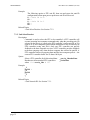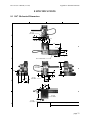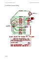
1
Computer Controlled
PAN-TILT UNIT
Model PTU-D47
USER’S MANUAL
Version 2.14.0
www.DPerception.com
Pan-Tilt Unit (Model PTU-D47) User’s Manual, Version 2.14.0,
March 5, 2007.
©1991,2007, 2009 by Directed Perception, Inc., 890C Cowan
Road, Burlingame, California 94010, (650) 692-3900, FAX:
(650)692-3900, www.DPerception.com.
All rights reserved. Protected under U.S. Patents 5463432 and
5802412. No part of this book may be reproduced, stored in a
retrieval system, or transcribed, in any form or by any means,
electronic, mechanical, photocopying, recording, or otherwise,
without the prior written permission of Directed Perception, Inc.
The information in this manual is subject to change without notice
and, except for the warranty, does not represent a commitment on
the part of Directed Perception. Directed Perception cannot be held
liable for any mistakes in this manual and reserves the right to make
changes.
Table of Contents
Pan-Tilt User’s Manual Version 2.14.0
1
INTRODUCTION ...................................................................................................1
1.1
IMPORTANT SAFEGUARDS AND WARNINGS....................................2
2
QUICK START........................................................................................................4
2.1
Overview......................................................................................................4
2.2
Installation Components ..............................................................................4
2.3
Required Components..................................................................................4
2.4
Basic Setup Steps.........................................................................................5
3
INSTALLATION & INITIAL SETUP ....................................................................6
3.1
Physical Mounting .......................................................................................6
3.2
Wiring and Connectors ................................................................................6
3.3
Power Sources..............................................................................................6
3.4
RS-232 Cable and Host Settings..................................................................8
3.5
Initial Power-up and Test .............................................................................9
3.6
Basic Pan-Tilt Unit Commands ...................................................................9
3.7
Mounting Your Camera or Other Payload ...................................................9
3.8
Payload Wiring Connections .....................................................................10
4
COMMAND REFERENCE ..................................................................................11
4.1
Binary Command Format ..........................................................................11
4.2
General ASCII Command Format .............................................................11
4.3
Positional Control Commands & Queries .................................................11
4.3.1 Position (absolute) .........................................................................11
4.3.2 Offset Position (relative offset)......................................................12
4.3.3 Resolution per Position..................................................................12
4.3.4 Limit Position Queries ...................................................................13
4.3.5 Position Limit Enforcement...........................................................13
4.3.6 Immediate Position Execution Mode.............................................14
4.3.7 Slaved Position Execution Mode ...................................................14
4.3.8 Await Position Command Completion ..........................................15
4.3.9 Halt Command ...............................................................................15
4.3.10 Monitor (Autoscan) Command ......................................................16
4.3.11 Position Presets ..............................................................................16
4.4
Speed Control Commands & Queries........................................................17
4.4.1 Speed Control & Relevant Terms ..................................................17
4.4.2 Speed (absolute).............................................................................17
4.4.3 Delta Speed (relative offset) ..........................................................18
4.4.4 Acceleration ...................................................................................19
4.4.5 Base (Start-Up) Speed....................................................................20
4.4.6 Speed Bounds ................................................................................20
4.4.7 Speed Control Modes.....................................................................21
Table of Contents
Pan-Tilt User’s Manual Version 2.14.0
4.5
4.6
4.7
4.8
Unit Commands .........................................................................................22
4.5.1 Reset Pan-Tilt Unit ........................................................................22
4.5.2 Default Save/Restore .....................................................................23
4.5.3 Echo Query/Enable/Disable...........................................................23
4.5.4 Feedback Verbose/Terse/Off ..........................................................23
4.5.5 Controller Firmware Version Query ..............................................24
4.5.6 Outside Supply Voltage and Controller Temperature Query .........24
Power Control Commands & Queries .......................................................24
4.6.1 Stationary Power Mode..................................................................25
4.6.2 In-Motion Power Mode .................................................................25
Host Serial Port and Control ......................................................................26
4.7.1 Configuring Host Serial Port Baud and Communications.............26
Step Modes.................................................................................................27
4.8.1 Configuring Step Mode..................................................................27
5
SPECIAL CONFIGURATIONS............................................................................28
5.1
High-Speed Operation ...............................................................................28
5.2
High-Payload Operation ............................................................................28
5.3
Battery-Powered Operation .......................................................................28
6
PTU OPTIONS.......................................................................................................29
7
NETWORKING ....................................................................................................30
7.1
Basic Networking Setup Steps...................................................................30
7.2
PTU Network Connections ........................................................................30
7.3
PTU Network Software Commands ..........................................................31
7.3.1 Unit Network ID ............................................................................31
7.3.2 Unit Select/Deselect.......................................................................32
8
SPECIFICATIONS ................................................................................................33
8.1
D47 Mechanical Dimensions....................................................................33
8.2
D47 Base Connector Wiring ......................................................................34
8.3
D47 Payload Flying Leads Mapping .........................................................35
REGULATORY INFORMATION.........................................................................36
LIMITED WARRANTY .......................................................................................37
PTU-D47 User’s Manual (v2.14.0)
INTRODUCTION
1 INTRODUCTION
The PTU-D47 Computer-Controlled Pan-Tilt Unit from Directed Perception provides lowcost, fast and accurate positioning of cameras and other payloads. Some general features:
• Simple to command from any RS-232 terminal or computer
• Small form factor
• Integrated controller
• Load capacity over 12 lbs. (5.48kg)
• Pan speeds over 300°/second
• Tilt speeds over 60°/second
• Pan resolution of 3.086 arc minute (.0514°)
• Tilt resolution of .7714 arc minute (.0129°)
• Precise control of position, speed & acceleration
• On-the-fly position and speed changes
• Self calibration upon reset
• Power consumption can be controlled from host
• ASCII command mode for simplicity, binary commands available for efficient program
control
• Constant current DMOS motor drives for increased performance and control
• Pass-through wiring for payload cable management
• DC power input from an unregulated source
The PTU-D47 series is electrically and software compatible with other Directed Perception
models including: PTU-D46, PTU-D300.
Applications of the PTU-D47 include:
• Robotics & computer vision
• Webcam
• Thermal and IR cameras
• Teleconferencing
• Advanced monitoring systems
• Tracking
• Photography, videography and special effects.
• Mid and Long-range Surveillance systems
• Automated detection and tracking
• Border Security & Law Enforcement
• Highway & Transportation Monitoring
• Military special operations
• Satellite communications systems
• Microwave antenna systems (passive, active)
• Robotics & computer vision
In addition, the PTU-D47 has flexible connectivity options.
This User’s Manual provides information needed to set up and operate the PTU-D47 unit.
The next section provides a quick overview to allow you to get started as quickly as possible.
More detailed technical information is provided in the remaining sections.
page 1
INTRODUCTION
PTU-D47 User’s Manual (v2.14.0)
1.1 IMPORTANT SAFEGUARDS AND WARNINGS
IMPORTANT SAFEGUARDS AND WARNINGS
1. Please read these instructions.
2. Please keep these instructions accessible.
3. Please heed all warnings.
4. Please follow all instructions.
5. Install in accordance with the Directed Perception’s instructions.
6. Do not install near any heat sources such as radiators, heat registers, stoves, or other
apparatus (including amplifiers) that produce heat.
7. Only use attachments/accessories specified by the Directed Perception.
8. Use only with the cart, stand, tripod, bracket, or table specified by the Directed Perception,
or sold with the apparatus.
9. Refer all servicing to qualified service personnel. Servicing is required when the apparatus
has been damaged in any way, such as power-supply cord or plug is damaged, liquid has
been spilled or objects have fallen into the apparatus, the apparatus has been exposed to rain
or moisture when improperly sealed, does not operate normally, or has been dropped.
10. Installation should be done only by qualified personnel and conform to all local codes.
11. The unit should not be installed in environments that present conditions beyond the
environmental specification limits of the apparatus.
12. Use only installation methods and materials capable of supporting four times maximum
specified load.
13. Use stainless steel hardware to fasten the mount to outdoor surfaces.
14. A readily accessible disconnect device shall be incorporated in the installation wiring.
15. CAUTION: These servicing instructions are for use by qualified service personnel
only. To reduce the risk of electric shock do not perform any servicing other that contained
in the operating instructions unless you are qualified to do so.
16. Only use replacement parts recommended by Directed Perception.
17. After replacement/repair of this unit’s electrical components, conduct a resistance
measurement between the line and exposed parts to verify the exposed parts have not been
connected to the line circuitry.
The product and/or manual may bear the following marks:
This symbol indicates that dangerous voltage
constituting a risk of electric shock is
present within this unit.
This symbol indicates that there are important
operating and maintenance instructions
in the literature accompanying this unit.
page 2
PTU-D47 User’s Manual (v2.14.0)
INTRODUCTION
WARNING: HAZARDOUS MOVING
PARTS. KEEP FINGERS AND OTHER
BODY PARTS AWAY.
CAUTION:
RISK OF ELECTRIC SHOCK.
DO NOT OPEN.
Models
PTU-D47
Standard base configuration. Includes integral controller, standard side+top
bracket.
PTU-D47P1
Includes payload pass-through wiring option (NOT 360-continous pan)
page 3
QUICK START
PTU-D47 User’s Manual (v2.14.0)
2 QUICK START
2.1 Overview
Figure 1 shows a system overview for typical applications. The PTU-D47 includes an
integral controller and accepts control commands from any host computer over it’s built-in
network interface (RS-232/RS-485). Signals such as video, power, and control from the
payload(s) are optionally routed internal to the unit and provided to a single base connector
The PTU-D47 can be controlled from any host computer using the built-in ASCII protocol
described in this manual, or binary protocol supported by the optional C API. Drivers are also
available in 3rd party software packages such as LabView and some digital video software
system.
Top mount bracket for
centered lighter loads
Side mount bracket
for heavy loads
Pan-Tilt Control (RS232/485)
Power (PTU) 8-30VDC
Payload Signals (8 Lines)
Flex cable port for 8 flying
leads to payload.
Figure 1: Pan-Tilt System Overview.
2.2 Installation Components
•
•
•
•
Components supplied with this manual are:
Pan-Tilt Unit
(optional) Pan-Tilt Cable
(optional) AC/DC Power Supply (model D47AC-APS-30V)
(optional) C Programmer’s Interface (model PTU-CPI)
Only move the pan-tilt axes using the knobs mounted on the pan-tilt unit motors.
Manual rotation of pan-tilt axes (called backdriving) can degrade unit
performance and accuracy.
2.3 Required Components
Besides payload-specific system elements, the items required for use of the PTU-D47
include:
• Hardware and tools for physical mounting of Pan-Tilt Unit and Payload(s)
• Connectors and tools for terminating Payload wiring connections
• Host Computer and software or terminal program for control of Pan-Tilt Unit
page 4
PTU-D47 User’s Manual (v2.14.0)
QUICK START
2.4 Basic Setup Steps
The following outlines the basic pan-tilt set-up and installation steps. Section 3 details each
of these steps.
1. Unpack Pan-tilt unit.
2. Physically mount Pan-tilt unit securely. See section 3.1 for details on mounting.
3. Connect a DC power source to Pan-Tilt power input (but do NOT apply power yet). The
optional Pan-Tilt Power Supply or an alternate power source may be used (see section 3.3
on page 6 and section 5 on page 28).
4. Connect an RS-232 or RS-485 cable between Pan-Tilt Control input and a host computer.
We recommend HyperTerminal (built-in to Windows) or equivalent for your initial testing.
Communications parameters such as baud rate etc. must be set properly in your host
terminal program (e.g., HyperTerminal) (see Section 3.4).
5. Power can be turned on and Pan-tilt operation can then be tested by typing commands into
your terminal program (See Section 3.6).
6. Section 3.6 describes some basic pan-tilt commands to get you going. Section 4 provides a
full description of all pan-tilt unit commands and queries.
7. You can now wire and mount your payload (e.g., camera) on the pan-tilt unit (see Section
3.7). Section 5 describes how to configure your pan-tilt for high speed operation.
page 5
INSTALLATION & INITIAL SETUP
PTU-D47 User’s Manual (v2.14.0)
3 INSTALLATION & INITIAL SETUP
This section describes the basic installation and setup steps required to get your pan-tilt
operational as quickly as possible. Unpack Pan-tilt unit.
3.1 Physical Mounting
The PTU-D47 is a powerful device and must be mounted securely to avoid damage to
equipment and injury to people. The Appendix shows the mounting hole pattern for the PTUD47. All of the provided mounting bolts should be used to secure the unit to a stable platform
capable of holding the weight of the unit plus the payload weight plus the additional force which
will be generated by the motion of the payload. A good rule of thumb is 4x the weight of the
payload plus the weight of the pan-tilt. So for example, for a 10 lb. payload, the platform should
be capable of stabily holding at least 40 lbs.
3.2 Wiring and Connectors
The wiring overview is shown in Figure 2. Pinouts for the various connectors are described in
Appendices 2 and 3.
Top mount bracket for
centered lighter loads
Side mount bracket
for heavy loads
Pan-Tilt Control (RS232/485)
Power (PTU) 8-30VDC
Payload Signals (8 Lines)
Flex cable port for 8 flying
leads to payload.
Figure 2: Wiring Overview
3.3 Power Sources
The PTU-D47 requires 9-30VDC (unregulated). Connect Pan-Tilt Unit power connections to
power source as shown in Figure 2.
In order to achieve the highest pan-tilt unit performance, use the highest motor voltage within
the allowable range. To achieve the quietest pan-tilt operation, use a lower motor voltage (e.g.,
12VDC).
CAUTION! When wiring your own power source, failure to comply with
wiring and power source requirements described in this manual can result
in decreased unit performance or damage not covered under the limited
warranty.
page 6
PTU-D47 User’s Manual (v2.14.0)
INSTALLATION & INITIAL SETUP
If you are providing your own DC power source, the power source must never supply more
than [3A] of current, and if so, you must add a [3A] Fast-Blow fuse in series with your DC
power source. For example, when connecting to a vehicle battery or lighter plug, you must fuse
the incoming DC source. Failure to properly fuse your input power source could cause
overloading of internal protection devices, pose a safety hazard, or void product warranties.
page 7
INSTALLATION & INITIAL SETUP
PTU-D47 User’s Manual (v2.14.0)
3.4 RS-232 Cable and Host Settings
An RS-232 terminal or host computer connects to the female DB-9 connector on the Pan-Tilt
Unit Controller (PTU-C). The host terminal or computer should be set to 9600 baud, 1 start bit, 8
data bits, 1 stop bit, and no parity. Hardware handshaking and XON/XOFF are not used.
The RS-232 connections to the Pan-Tilt Controller female DB-9 are: TxD (pin 2), RxD (pin
3), and GND (pin 5). You will need to obtain a cable that connects the host RS-232 port to the
controller DB-9 connector. Figure 3 shows cable configurations for some common computer
hosts. Since TxD and RxD assignments to pins 2 and 3 can vary on host computers, try using a
null modem if your initial connection does not work.
IBM PC, XT
Asynch Card DB-25S
TxD (pin 2)
RxD (pin 3)
GND (pin 7)
DTR (pin 20)
DSR (pin 6)
PTU-C
(female DB-9)
RxD (pin 3)
TxD (pin 2)
GND (pin 5)
(pin 4)
(pin 6)
IBM AT
Asynch Card DB-9S
RxD (pin 2)
TxD (pin 3)
GND (pin 5)
DTR (pin 4)
DSR (pin 6)
PTU-C
(female DB-9)
TxD (pin 2)
RxD (pin 3)
GND (pin 5)
(pin 4)
(pin 6)
Apple Macintosh
8 Pin Mini-DIN
TxD (pin 3)
RxD (pin 5)
GND (pin 4)
DTR (pin 1)
DSR (pin 2)
PTU-C
(female DB-9)
TxD (pin 2)
RxD (pin 3)
GND (pin 5)
(pin 4)
(pin 6)
Null modem may
be required.
Figure 3: RS-232 Pan-Tilt Controller Connection to Common Hosts
page 8
PTU-D47 User’s Manual (v2.14.0)
INSTALLATION & INITIAL SETUP
3.5 Initial Power-up and Test
If you have the power source and Host computer connected described in Sections 3.3 and 3.4,
you are ready to power-up and test its operation. Test and verify all cable connections and
connector wiring before power-up. We suggest that you do not mount your payload (e.g., camera)
until this initial installation is completed and tested.
1. Using HyperTerminal or a similar terminal program, configure the RS-232/485 serial port of
the Host Computer to 9600 baud, 1 start bit, 8 data bits, 1 stop bit, and no parity. Hardware
handshaking and XON/XOFF are not used.
2. You are now ready to power up the pan-tilt unit and test its operation. Apply power. Upon
power up, introduction text should appear on your screen, and the pan-tilt unit should go
through a reset cycle (pan and tilt axes will cycle through their full range of motion). This
reset is completed when an asterisk (‘*’) appears. If the unit did not reset properly, recheck
your power source and cabling. If the unit went through its reset procedure, but no text or
garbled text appears on your screen, then:
• Check that the host RS-232/RS-485 host port settings are correct (see Section 3.4)
• Check that the RS-232/RS-485 cable is correct for your host (see Section 3.4)
3. You are now connected to the pan-tilt. Enter the character ‘?’ for a complete listing of
commands. The next section describes some basic commands to help you get going, and a
full command description may be found in Section 4. We suggest that you exercise the unit
and become familiar with its operation and commands before mounting your payload (e.g.,
camera) as described in Section 3.7. Special attention should be paid to acceleration and
speed commands, and they should be set at levels appropriate to your payload weight and
size..
3.6 Basic Pan-Tilt Unit Commands
Below are some pan-tilt commands that will familiarize you with the pan-tilt unit and its
operation:
pp2500 *
tp-900 *
ps2500 *
pp0 *
This sets the pan axis to position 2500, the tilt axis to position -900, the pan speed to 2500
positions a second, and sets the pan position back home.
When operating the pan-tilt unit, the available command menu is printed when you enter the
‘?’ character. A detailed description of pan-tilt commands and queries may be found in Section 4.
3.7 Mounting Your Camera or Other Payload
Your camera or other load attaches to the side and/or top mounting plate on the Pan-Tilt Unit.
The side-mount bracket can be removed and replaced with standard top load plate.
Though the pan-tilt unit is rated to a specific maximum load, the distribution of the load
clearly affects the actual load capable of being moved by the pan-tilt unit. The steps to determine
whether your load is within the maximum load capacity and dynamics are:
• Mount your load. Attempt to center the load’s center of mass close to the hole in the
mounting plate, and close to the center of rotation of the tilt axis. Ensure that the load is
securely attached to the mounting bracket.
page 9
INSTALLATION & INITIAL SETUP
•
•
•
•
•
PTU-D47 User’s Manual (v2.14.0)
First move the pan axis through its range to test whether the pan-tilt can handle the load
(e.g., enter “dr pp2700 a pp-2700 a pp0 ”). A load that is too heavy or moved too
quickly will cause the unit to lose synchrony, and this will be accompanied by an audible
“rrrr” sound from the pan-tilt unit motors.
If your load passed the pan axis load test, you can then test the tilt axis load handling
capability. Because the tilt axis requires more power to move the load, it is more likely to
lose synchrony for excessive loads or load weight distributions. Move the tilt axis through
its range to test whether the pan-tilt can handle the load (e.g., enter “dr tp-900 a
tp600 a tp0 “). A load that is too heavy or moved too quickly will cause the unit to lose
synchrony, and this will be accompanied by an audible “rrrr” sound from the pan-tilt unit
motors.
If your load fails the above pan or tilt axis load handling tests, contact Directed Perception
for further assistance.
If your load passes the above pan and tilt axis load handling tests, you are ready to begin
controlling you load using the commands describe in Section 4.
The initial pan-tilt unit parameters ensure the highest load movement torque that can be
generated from the pan-tilt unit. Significantly faster or lower power control can be obtained
via commands to the pan-tilt unit. The speed and acceleration of a mechanical system
depends upon the inertial properties of your load. The ability of the pan-tilt unit to
successfully move your load without losing synchrony depends upon the inertial load
factors and their relationship to power supply voltage, unit speed, acceleration, position,
motor torque, etc. Section 5 discusses how to configure pan-tilt parameters to achieve more
optimal pan-tilt unit performance for your load.
3.8 Payload Wiring Connections
The PTU-D47 optionally supports routing of payload wiring through the Pan-tilt unit to the
single base connector. These signals are provided as a cable of flying leads from the pedestal that
can be attached to the payload terminal block or custom connector. Pin-outs and signal
descriptions are provided in Appendix A.4.
• Care must be taken that all payload signals are within the specified capabilities of the passthrough signals such as max voltages and current levels.
page 10
PTU-D47 User’s Manual (v2.14.0)
COMMAND REFERENCE
4 COMMAND REFERENCE
This section describes the pan-tilt unit command set. Each command has a section that
provides a brief functional description, a format (syntax) description, examples, and related
topics. When controlling the pan-tilt unit from a terminal, a complete menu of pan-tilt commands
can be obtained by entering the character “?”.
4.1 Binary Command Format
A C Programmer’s Interface (model PTU-CPI) is available for higher bandwidth binary
communications between a host computer and the PTU controller.
4.2 General ASCII Command Format
When describing the format (syntax) of pan-tilt commands, the following conventions are
adopted:
• Commands issued to the pan-tilt unit (e.g., typed in by you) are shown in bold.
• Input characters may be in upper or lower case (we show them in upper case for
presentational consistency)
• A delimiter (<delim>) can be either a space (“ ”) or a carriage return (<CR>).
• A successfully executed command returns “*<CR>”. Successful query execution returns
“* <QueryResult><CR>”.
Command
execution
failure
returns
“! <ErrorMessage><CR>”. A pan axis limit hit asynchronously returns “!P” and a tilt
axis limit hit asynchronously returns “!T”.
4.3 Positional Control Commands & Queries
4.3.1 Position (absolute)
Description:
Specify or query the absolute pan or tilt axis position. Desired positions can
be changed on-the-fly without waiting for previous position commands to
complete.
Syntax
Query current absolute pan position: PP<delim>
Set desired absolute pan position:
PP<position><delim>
Query current absolute tilt position:
TP<delim>
Set desired absolute tilt position:
TP<position><delim>
Example
The following sends the pan axis to the left, waits, then sends it to the right:
PP-2500 *
A *
PP * Current Pan position is -2500
PP2500 *
A *
PP * Current Pan position is 2500
page 11
COMMAND REFERENCE
PTU-D47 User’s Manual (v2.14.0)
Related Topics
• Position (relative offset and desired position queries): See Section 4.3.2
• Position resolution (units): See Section 4.3.3
• Position limits: See Section 4.3.4
• Position execution modes: See Sections 4.3.6, 4.3.7 and 4.3.8
• Position limit enforcement modes: See Section 4.3.5
4.3.2 Offset Position (relative offset)
Description
Specify desired axis position as an offset from the current position, or Query
the current axis position. Desired offset positions can be changed on-the-fly
without waiting for previous position commands to complete.
Syntax
Query desired pan position:
PO<delim>
Set desired offset pan position: PO<position><delim>
Query desired tilt position:
TO<delim>
Set desired offset tilt position: TO<position><delim>
Example
The following sends the pan axis to position -500, then sends it 1500
positions to the left:
PP-500 *
A *
PO * Current Pan position is -500
PO1500 *
A *
PP * Current Pan position is 1000
Related Topics
• Position resolution (units): See Section 4.3.3
• Position limits: See Section 4.3.4
• Position execution modes: See Sections 4.3.6, 4.3.7 and 4.3.8
• Position limit enforcement modes: See Section 4.3.5
4.3.3 Resolution per Position
Description
Query returns the axis resolution per position moved (in seconds/arc).
Syntax
Query pan resolution:
PR<delim>
Query tilt resolution:
TR<delim>
Example
Resolution can be determined by:
PR * 185.1428 seconds arc per Pan position
1 sec arc = 1/(60 min arc * 60 sec arc) = .0002778°. So 185.1428 seconds arc
equals (185.1428 sec arc * .002778°) = 0.0514285°. Thus, to pan 21.3° left
requires a relative move of (21.3°/0.0514285°) ≈ 414 positions, yielding the
following command:
PO414 *
page 12
PTU-D47 User’s Manual (v2.14.0)
COMMAND REFERENCE
Related Topics
• Factory options are available to achieve higher resolution or accuracy.
4.3.4 Limit Position Queries
Description
Queries return the axis position bounds determined upon unit reset.
Syntax
Query minimum pan position: PN<delim>
Query maximum pan position: PX<delim>
Query minimum tilt position: TN<delim>
Query maximum tilt position: TX<delim>
Example
R *
PN * Minimum Pan position is -3090
PX * Maximum Pan position is 3090
TN * Minimum Tilt position is -907
TX * Maximum Tilt position is 604
LE *
PP3200 ! Maximum allowable Pan position is 3090
Related Topics
• Position resolution (units): See Section 4.3.3
• Achieving larger axis bounds: See Section 4.3.5
4.3.5 Position Limit Enforcement
Description
Determines whether position commands beyond the detected pan and tilt axis
limits are allowable. The default is position limits are enabled (i.e., enforced).
Enabling position limits ensures that all positions within the limits can
be achieved when the load does not extend below the bottom of the load
mounting plate (see Section 3.7). When limits are enabled, commands
outside of the limits return an error message and are not executed. In enabled
limit mode, limits are only be reached when the unit has lost synchrony and
this error condition requires a unit reset (see Section 4.5.1). When a limit is
reached either “!P” or “!T” is printed to indicated which axis limit was hit
(pan or tilt).
When larger operational ranges are required, the limits may be disabled.
Positional commands outside the limits are not rejected when limits are
disabled. Positions outside the limits introduce the possibility that the tilt axis
and load can interfere with the pan axis, so it is important that accessibility of
positions outside the limits be determined.
Syntax
Query the current position limit mode: L<delim>
Enable position limits:
LE<delim>
Disable position limits:
LD<delim>
page 13
COMMAND REFERENCE
PTU-D47 User’s Manual (v2.14.0)
Example
L * Limit bounds
PX * Maximum Pan
PP3200 ! Maximum
LD *
PP3200 *
A *
PP * Current Pan
are ENABLED (soft limits enabled)
position is 3090
allowable Pan position is 3090
position is 3200
Related Topics
• Position commands: See Sections 4.3.1 and 4.3.2
4.3.6 Immediate Position Execution Mode
Description
Instructs pan-tilt unit to immediately execute positional commands. This is
the default mode.
Syntax
I<delim>
Example
For the below commands, the pan axis will immediately execute the pan
position command:
I *
PP1000 *
Related Topics
• Alternative slaved position execution mode: See Section 4.3.7
4.3.7 Slaved Position Execution Mode
Description
Instructs pan-tilt unit to execute positional commands only when an Await
Position Command Completion command is executed (see Section 4.3.8) or
when put into Immediate Execution Mode (see Section 4.3.6). This mode is
useful when coordinated pan and tilt axis movements are desired.
Syntax
S<delim>
Example
The following commands change the position execution mode, instruct the
axes which position to achieve, and an await command causes the position
commands to be executed simultaneously:
DR *
S *
PP1500 *
TP-900 *
PP * Current Pan position is 0
TP * Current Tilt position is 0
A *
PP * Current Pan position is 1500
TP * Current Tilt position is -900
Related Topics
• Alternative immediate position execution mode: See Section 4.3.6
page 14
PTU-D47 User’s Manual (v2.14.0)
COMMAND REFERENCE
4.3.8 Await Position Command Completion
Description
Awaits the completion of the last issued pan and tilt axis position commands.
Used to coordinate axis motions.
Syntax
A<delim>
Example
The following commands instruct the pan axis to move to a position, then
move to another position:
I *
PP * Current Pan position is 0
PP2000 *
A *
PP * Current Pan position is 2000
PP0 *
A *
PP * Current Pan position is 0
In contrast, the following commands would begin to move to the first
position, and before that position is reached, the next position would be
moved towards (this is often called an on-the-fly position change):
I *
PP * Current Pan position is 0
PP2000 *
PP0 *
Related Topics
• This command can be used for both the Immediate Position Execution
Mode (see Section 4.3.6) and Slaved Position Execution Mode (see Section
4.3.7)
4.3.9 Halt Command
Description
Immediately decelerates and halts pan-tilt movement.
Syntax
Halt all pan-tilt movement:
H<delim>
Halt pan axis movement:
HP<delim>
Halt tilt axis movement:
HT<delim>
Example
PP2500 *
A *
PP-2500
Then while the pan-tilt is moving, the host decides to stop immediately:
H *
Related Topics
• This command can be used for both the Immediate Position Execution
Mode (see Section 4.3.6) and Slaved Position Execution Mode (see Section
4.3.7)
page 15
COMMAND REFERENCE
PTU-D47 User’s Manual (v2.14.0)
4.3.10 Monitor (Autoscan) Command
Description
Command defines and initiates repetitive monitoring (scanning) of the pantilt. Autoscanning is immediately terminated upon receipt of a character from
the host computer, and the pan-tilt is sent to its home position.
Syntax
Initiate monitor (autoscan) in pan axis only:
M<pan pos 1>,<pan pos 2><delim>
Initiate monitor (autoscan) in both pan and tilt axes:
M<pan pos 1>,<pan pos 2>,<tilt pos 1>,<tilt pos 2><delim>
Initiate last defined monitor (autoscan) command (the default at power up is
pan axis only autoscan between the pan limit positions):
M<delim>
Enable monitor (autoscan) at power up:
Disable monitor (autoscan) at power up:
Query monitor status at power up:
ME<delim>
MD<delim>
MQ<delim>
Example
When executed at power up,
M *
the pan-tilt begins scanning between the minimum and maximum pan limit
positions.
<delim>
terminates the scanning and homes the pan-tilt. Other monitoring command
forms:
M-2500,100 *
M-2500,100,-800,600 *
M0,0,-300,300 *
Related Topics
• Limit Position Queries (see Section 4.3.4)
4.3.11 Position Presets
Description
Position preset functionality is provided for backward compatibility with
legacy CCTV applications. D47 pan-tilt controller firmware version v2-1211r2 and higher support position presets. The pan-tilt can be commanded to a
position using any of the standard motion control commands of the D47 PTU.
The current pan and tilt position can be stored as a numbered “preset”. The
PTU can then be commanded to a previously stored preset using a new “go to
preset” command. Currently set motion parameters (acceleration, base rate,
etc.) apply during “go to preset” commands. Preset positions are remembered
when the controller is repowered.
Syntax
XS<index><delim> where <index> ? [0..32]
XG<index><delim> where <index> ? [0..32]
XC<index><delim> where <index> ? [0..32]
“Set Preset”
“Goto Preset”
“Clear Preset”
Example
The following commands set the Pan/Tilt to position 500/400, store as preset
0, move the unit to position 600/800, and then goes back to previously stored
preset 0 position.
page 16
PTU-D47 User’s Manual (v2.14.0)
COMMAND REFERENCE
PP500 *
TP400 *
XS0 *
PP600 *
TP800 *
XG0
4.4 Speed Control Commands & Queries
4.4.1 Speed Control & Relevant Terms
The Pan-Tilt Unit provides for precise control of axis speed and acceleration. This subsection
briefly describes how speed control is performed and it introduces relevant terms.
As shown in Figure 4, upper and lower speed limits determine the bounds on nonstationary
pan-tilt velocities. The base (start-up) speed specifies the velocity at which the pan-tilt axis can be
started from a full stop without losing synchrony (as described in Section 3.7), and it is more a
function of the motors rather than load characteristics. Due to base speed requirements and the
property that motors lose torque as speed increases, acceleration is required to achieve axis speeds
above the base rate. The pan-tilt controller uses trapezoidal acceleration and deceleration for
speeds above the base rate and less than the maximum allowed speed. Figure 4 shows two
acceleration cases. In the first, an axis accelerates up to a desired constant speed (slew rate), then
decelerates. The second case shows the case when the unit does not have sufficient time to
accelerate up to the desired slew speed before the need to decelerate to the desired position.
The pan-tilt controller provides for on-the-fly position and speed changes. If the direction is
changed on-the-fly, the controller manages all deceleration, direction reversal, and acceleration to
achieve the most recently specified target pan-tilt speed and acceleration rates.
Because speed, acceleration, and position are precisely controlled, you can accurately and
simply predict the position attained by the pan-tilt unit in time.
UPPER SPEED LIMIT
speeds
requiring
acceleration
BASE (start-up) SPEED
instantaneous
speed
changes
LOWER SPEED LIMIT
time
Figure 4: Axis Speed, Instantaneous Speeds, Trapezoidal Acceleration,
and On-The-Fly Speed and Position Changes
4.4.2 Speed (absolute)
Description
Specify or query desired axis speed. Desired speed is specified in positions/
second and it can be changed on-the-fly. The speed specifies that rate at
which the pan-tilt move to achieve position movement commands.
page 17
COMMAND REFERENCE
PTU-D47 User’s Manual (v2.14.0)
Desired speed commands outside the speed bounds return an error and
are not executed.
Syntax
Query desired pan speed:
Set desired pan speed:
PS<delim>
PS<positions/sec><delim>
Query desired tilt speed:
Set desired tilt speed:
TS<delim>
TS<positions/sec><delim>
Example
The following commands instruct the pan axis to move to the far left, then
slowly move right, and then on-the-fly it speeds up:
I *
PS2500 *
PP2600 *
A *
PS600 *
PP-2600 *
PS2500 *
Related Topics
• Position commands: See Section 4.3.1 - 4.3.2
• Position resolution (units): See Section 4.3.3
• Speed bounds: See Section 4.4.6
4.4.3 Delta Speed (relative offset)
Description
Specify desired axis speed as an offset from the current speed, or Query the
current axis speed. Desired delta (offset) speed is specified in positions/
second and it can be changed on-the-fly. A desired delta speed command that
results in a speed outside the legal speed bounds returns an error and it is not
executed.
Syntax
Query current pan speed:
PD<delim>
Set desired delta (offset) pan speed: PD<positions/sec><delim>
Query current tilt speed:
TD<delim>
Set desired delta (offset) tilt speed: TD<positions/sec><delim>
page 18
PTU-D47 User’s Manual (v2.14.0)
COMMAND REFERENCE
Example
The following commands instruct the pan axis to move to the far left, then
slowly move right, and then on-the-fly it decreases speed by -150 positions/
second, then queries the current speed:
I *
PS2500 *
PP2600 *
A *
PS600 *
PP-2600 *
PD-150 *
PD * Current Pan speed is 520 positions/sec
Related Topics
• Position commands: See Section 4.3.1 - 4.3.2
• Position resolution (units): See Section 4.3.3
• Speed bounds: See Section 4.4.6
4.4.4 Acceleration
Description
Specify or query axis acceleration and deceleration for speeds above the base
speed. Acceleration is specified in positions/second2.
Syntax
Query desired pan acceleration: PA<delim>
Set desired pan acceleration: PA<positions/sec2><delim>
Query desired tilt acceleration: TA<delim>
Set desired tilt acceleration:
TA<positions/sec2><delim>
Example
The following illustrate different rates of acceleration:
PA * Pan acceleration is 2000 positions/sec^2
PB * Current Pan base speed is 1000 positions/sec
PU * Maximum Pan speed is 2902 positions/sec
PP0 *
PS2900 *
PP2600 *
PA8000 *
PP0 *
Related Topics
• Position resolution (units): See Section 4.3.3
• Symmetric trapezoidal acceleration is used, so the rate of deceleration is
equivalent to the rate of acceleration
• Acceleration cannot be changed on-the-fly since it takes several seconds to
recompute the internal tables used to rapidly execute speed ramping.
page 19
COMMAND REFERENCE
PTU-D47 User’s Manual (v2.14.0)
4.4.5 Base (Start-Up) Speed
Description
Specify or query axis base (start-up) speed. Base speed is specified in
positions/second. Defaults to 1000 positions/sec.
Syntax
Query desired pan base speed: PB<delim>
Set desired pan base speed:
PB<positions/sec><delim>
Query desired tilt base speed: TB<delim>
Set desired tilt base speed:
TB<positions/sec><delim>
Example
The following commands home the pan axis, moves it far left, changes the
base rate, then moves back to home:
I *
PP0 *
A *
PP2600 *
PB * Current Pan base speed is 1000 positions/sec
PB1000 *
PP0 *
Related Topics
• Position resolution (units): See Section 4.3.3
• Acceleration: See Sections 4.4.1 and 4.4.4
• Speed bounds: See Section 4.4.6
• Changes in the base rate cannot be made on-the-fly since it takes several
seconds to recompute the internal tables used to rapidly execute speed
ramping.
4.4.6 Speed Bounds
Description
Set and query the upper and lower speed bounds for desired speed
commands.
Syntax
Query upper pan speed limit: PU<delim>
Set upper pan speed limit:
PU<positions/sec><delim>
Query lower pan speed limit: PL<delim>
Set lower pan speed limit:
PL<positions/sec><delim>
Query upper tilt speed limit:
Set upper tilt speed limit:
Query lower tilt speed limit:
Set lower tilt speed limit:
page 20
TU<delim>
TU<positions/sec><delim>
TL<delim>
TL<positions/sec><delim>
PTU-D47 User’s Manual (v2.14.0)
COMMAND REFERENCE
Example
PU * Maximum Pan speed is 2902 positions/sec
PS3300 ! Pan speed cannot exceed 2902 positions/sec
PS2900 *
PL * Minimum Pan speed is 31 positions/sec
PL20 ! Motor speed cannot be less than 31 pos/sec
PL40 *
Related Topics
• Position resolution (units): See Section 4.3.3
• Changes in the upper speed limit cannot be made on-the-fly since it takes
several seconds to recompute the internal tables used to rapidly execute
speed ramping.
4.4.7 Speed Control Modes
Description
By default, position control commands are independent from the speed
control commands. In this independent control mode, the commanded speed
is an unsigned magnitude that determines the speed at which independently
commanded positions are effected, and the execution of these speed
commands do not affect the commanded desired positions themselves. This
mode is appropriate for pure position control methods (when pan-tilt control
is effected solely by commanding pan-tilt position) and hybrid positionvelocity control methods (when pan-tilt positions and the rate at which they
are achieved are both controlled).
An alternative pan-tilt control method uses a pure velocity control mode
in which all pan-tilt control is effected by signed changes in command axis
speed. In this mode, the speed command specifies a signed velocity in which
the sign determines the direction of axis movement, and the ordinal value
specifies the speed of movement in this direction. In this mode, if the
commanded speed is negative, the axis is automatically commanded to the
minimum axis position. Conversely, if the speed command is positive, the
axis is automatically commanded to the maximum axis position. A speed of
zero is applied by halting the axis motion. It is important to note that that in
pure velocity control mode, a speed command for a given axis effectively
overrides currently executing position commands. As a result, the speed
control mode at power up is always set to independent control mode; the
speed control mode is not saved as defaults that are preserved when the unit
is powered back up.
These commands are available in PTU firmware versions 1.09.7 and
higher.
Syntax
Query the current speed control mode:
C<delim>
Set to independent control mode (default): CI<delim>
Set to pure velocity control mode:
CV<delim>
page 21
COMMAND REFERENCE
PTU-D47 User’s Manual (v2.14.0)
Example
Put into the default independent control mode, the pan-tilt will finish at
position -3000. Put in the pure velocity control mode, the pan-tilt will finish
on the opposite pan side. Note that the default restore (also executed upon
unit power up) restores the unit to independent control mode:
CI *
PP-3000 *
PS1000 *
A *
CV *
PP-3000 *
PS1000 *
DR *
PP-3000 *
PS1000 *
Related Topics
• Position commands: See Section 4.3.1-4.3.2
• Speed commands: See Section 4.4.2-4.4.3
4.5 Unit Commands
4.5.1 Reset Pan-Tilt Unit
Description
This command controls how, and when, the pan-tilt unit is calibrated. By
default, the pan-tilt unit is configured to reset both the pan and tilt axes
automatically upon power up and by issuing the reset command.
The reset mode commands are used to control the reset performed at pantilt power up, and to allow reset of an individual pan-tilt axis. The reset
calibration allows the pan-tilt unit to determine axis coordinates, hence a
pan-tilt axis should be reset prior to issuing any axis position commands. A
pan-tilt axis that has not been calibrated has a minimum and maximum axis
position of 0 (see Section 4.3.4), hence position commands in limit enabled
mode (see Section 4.3.5) will return an illegal position command feedback.
Syntax
Performs Reset calibration:
R<delim>
Reset modes (saved in internal EEPROM for power up reset control):
Disable reset upon power up:
RD<delim>
Reset tilt axis only:
RT<delim>
Reset pan axis only:
RP<delim>
Reset both pan and tilt axes upon power up: RE<delim>
page 22
PTU-D47 User’s Manual (v2.14.0)
COMMAND REFERENCE
Example
RT *
R *
RP *
R *
RD *
R *
RE *
R *
Related Topics
• A load beyond the handling capacity of the pan-tilt unit may cause the reset
to fail, so load handling capability should be tested as described in Section
3.7.
4.5.2 Default Save/Restore
Description
Allows current axis settings to be saved as defaults that are preserved when
the unit is powered back up. Also allows the factory defaults to be restored.
Syntax
Save current settings as defaults: DS<delim>
Restore stored defaults:
DR<delim>
Restore factory defaults:
DF<delim>
Related Topics
• Defaults are saved in EEPROM which have a lifetime limit on the number
of writes before memory failure. Though it is unlikely that these failure
limits will be reached, excessive saving of current defaults should be
avoided when possible.
4.5.3 Echo Query/Enable/Disable
Description
Sets of queries whether the pan-tilt controller echoes incoming commands
from the host.
Syntax
Query current echo mode:
E<delim>
Enable host command echoing:
EE<delim>
Disable host command echoing:
ED<delim>
Example
PP * 22
ED *
<pp entered again, but not echoed>* 22
4.5.4 Feedback Verbose/Terse/Off
Description
Command and query the ASCII feedback returned by PTU commands.
page 23
COMMAND REFERENCE
PTU-D47 User’s Manual (v2.14.0)
Syntax
Enable verbose ASCII feedback:
Enable terse ASCII feedback:
Query ASCII feedback mode:
FV<delim>
FT<delim>
F<delim>
Example
FV *
PP * Current pan position is 0
FT *
PP * 0
F * ASCII terse mode
4.5.5 Controller Firmware Version Query
Description
Query specifies the version and copyrights for the pan-tilt controller
firmware.
Syntax
V<delim>
Example
V * Pan-Tilt Controller v2.12.1d1(C14/E), (C)2003 Directed Perception, Inc., All
Rights Reserved
4.5.6 Outside Supply Voltage and Controller Temperature Query
Description
The D47 hardware includes sensors for the internal case temperature and the
input voltage supplied to the controller power receptacle. This query
measures and prints the controller temperature and input supply voltage.
Syntax
O<delim>
Example
O * Input 30 VDC @ 86 degF
4.6 Power Control Commands & Queries
A key advantage of the constant current motor control drivers used in the Pan-Tilt Controller
is that it allows the current consumed by the pan-tilt unit to be controlled via simple unit
commands. These capabilities are useful for battery powered operation (see Section 7), reducing
unit heat generation, and extending the rated life of the motor driver circuitry.
page 24
PTU-D47 User’s Manual (v2.14.0)
COMMAND REFERENCE
4.6.1 Stationary Power Mode
Description
Set and query the current level applied to axis motors when not in-transit.
Syntax
Query pan hold power mode:
PH<delim>
Regular pan hold power mode:
PHR<delim>
Low pan hold power mode:
PHL<delim>
Off pan hold power mode:
PHO<delim>
Query tilt hold power mode:
Regular tilt hold power mode:
Low tilt hold power mode:
Off tilt hold power mode:
TH<delim>
THR<delim>
THL<delim>
THO<delim>
Example
PH * Pan in REGULAR hold power mode
PHL *
PH * Pan in LOW hold power mode
Related Topics
• Because holding torque for steppers is significantly greater than generated
dynamic torque, it is highly recommended that Low Hold Power Mode be
used when appropriate for your load. Regular hold power is intended to be
used for brief periods when very high holding torque may be required; this
requirement is rare. Regular hold power mode should be avoided or used
sparingly, as its use for long periods of time can lead to significant motor
and controller heating (depending on ambient temperature).
• When using Off Hold Power Mode, fully test that your load does not
backdrive the unit when stationary. Backdriving will cause the controller to
lose track of pan-tilt position, and this requires that the unit be reset (see
Section 4.5.1). Backdriving is more likely on the tilt axis which has higher
torque applied to it by the load.
4.6.2 In-Motion Power Mode
Description
Set and query the current level applied to axis motors when in-motion (intransit).
Syntax
Query pan move power mode:
PM<delim>
High pan move power mode:
PMH<delim>
Regular move hold power mode: PMR<delim>
Low pan move power mode:
PML<delim>
Query tilt move power mode:
High tilt move power mode:
Regular tilt move power mode:
Low tilt move power mode:
TM<delim>
TMH<delim>
TMR<delim>
TML<delim>
page 25
COMMAND REFERENCE
PTU-D47 User’s Manual (v2.14.0)
Example
PM * Pan in REGULAR move power mode
PML *
PM * Pan in LOW move power mode
Related Topics
• It is not recommended that an axis be in transit more than half the time
when in High Move Power Mode (i.e., a 50% duty cycle).
4.7 Host Serial Port and Control
As was described in Section 3, default host computer communications with the pan-tilt
controller is 9600 baud. Host computer communications can be via RS-232, or as described in
Section 7 it can be via the built-in RS-485.
Host serial port baud rates can be modified from the default. Also, a character delay may be
specified for applications that cannot consume pan-tilt output rapidly enough.
4.7.1 Configuring Host Serial Port Baud and Communications
Description
Command specifies the baud rate for the host serial port RS232/RS485
communications with the pan-tilt controller. Only baud rate can be modified.
The pan-tilt controller RS232/485 communications always use 1 start and
stop bit, 8 data bits and no handshaking. The command also allows a
transmission delay to be placed between bytes output by the pan-tilt
controller.
The host serial port command in this Section 4.7.1 is only available
when the controller is not networked (i.e., the unit ID is the default of 0).
When the controller is networked (i.e., unit ID is greater than 0), the host
serial port communications rate is automatically set to the default and it
cannot be modified by this command: the default is 9600 baud, 8 data bits, 1
start and stop bit, no parity, no handshaking, and no byte transmission delay.
This ensures that networked controllers will always communicate at the same
baud rate, and that higher data rates will not unduly burden pan-tilt controller
processors.
Syntax
@(<baud>,<byte delay in msec>,<startup default>)<delim>
where:
may be 600, 1200, 2400, 4800, 9600, 19200 or 38400 bits/
sec
<byte delay in msec> is the time in milliseconds the pan-tilt controller
waits between transmitting output data. If no delay is desired, use a
parameter of 0, otherwise, the delay may vary from 10 ms to 1000 ms.
<startup default> If T, <baud> and <byte delay in msec> are
applied at power up; otherwise, the power up default is 9600 baud with
no byte transmission delay.
<baud>
page 26
PTU-D47 User’s Manual (v2.14.0)
COMMAND REFERENCE
Example
The following command sets the host serial port RS232/RS485 to a baud rate
of 38,400 bits/second (8 data bits per byte, no parity, no handshaking), no
delay in controller outbound byte transmission, and the power up baud rate is
the system default of 9600 baud.
@(38400,0,F) *
The following command sets the host serial port RS232/RS485 to a baud rate
of 19,200 bits/second (8 data bits per byte, no parity, no handshaking), a
30ms delay between bytes output from the pan-tilt controller, and the power
up baud rate overrides the default and is set at 19,200 baud.
@(19200,30,T) *
Related Topics
• To wire the host port serial RS232 communications : See Section 3.4
• To wire the host port serial RS485 communications : See Section 7.2
• To set the pan-tilt controller unit ID : See Section 7.3.1
4.8 Step Modes
4.8.1 Configuring Step Mode
Description
The default motion resolution of the D47 controller is half step mode.
Firmware versions 2.12.8 and higher added microstepping in quarter and
eighth steps. Microstepping provides much quieter operation and smoother
motion at slow speeds. In addition, the microstepping increases the effective
resolution of the pan-tilt unit.
Firmware versions 2.13.0 and higher added autostep electronic gearing.
The controller will automatically select the correct step mode based on the
pan-tilt’s current speed, and process all units as though the unit were in eighth
step mode while allowing the unit to move at the higher speeds of half step.
Syntax
W<axis><resolution> where
<axis> :== T | P
<resolution> :== F | H | Q | E | A
for Full, Half, Quarter, Eighth and Auto step
resolution.
Example
The following command puts the tilt axis into eighth step resolution and
recalibrates the tilt axis, which returns success (*).
WTE *
Known Issues
• Autostep mode is only supported in firmware versions v2.13.0 and higher.
This firmware supports querying the step mode with the
“W<axis><delimiter>” command.
• Microstepping decreases the pull-out torque of the motor.
page 27
SPECIAL CONFIGURATIONS
PTU-D47 User’s Manual (v2.14.0)
5 SPECIAL CONFIGURATIONS
5.1 High-Speed Operation
This section discusses how to improve high speed pan-tilt unit performance for your load.
The primary factors that affect high speed operation are:
• Load weight, weight distribution and dynamics
• Desired upper speed limit (see Section 4.4.6)
• Rate of acceleration (see Section 4.4.4)
• The base (start-up) speed (see Section 4.4.5)
• The voltage of the source power supply. Use of the highest available voltage in the range 930VDC significantly improves axis speed and acceleration performance.
• The in-motion power mode (see Section 4.6.2) and stationery power mode (see Section
4.6.1).
• Multiaxis dynamics. Simultaneously moving the tilt and pan axes affects the forces exerted
on the pan axis.
High speed operation tests should always begin on each axis in isolation. When the best
performance for each axis in isolation is understood, high speed operation of simultaneous pan-tilt
axis movements can be performed.
An example configuration string for high speed operations is:
PA9000 PU6000 TA9000 PU6000 DS
5.2 High-Payload Operation
This section discusses how to improve high payload weight operation of the pan-tilt. The
payload factors listed in the previous section outlined factors that affect payload carry capacity.
The primary factor affecting payload capacity is the tilt axis, as it is a lever which is an
efficient force multiplier. The primary means to increase payload capacity are:
• Configure the pan-tilt controller for maximum torque. An example configuration string to
maximize payload capacity is:
PU2000 PA2000 PB60 TU2000 TA2000 TB60 PMR TMR %%1R600 DS
•
•
•
If your move duty cycle is less than 50%, you can alternatively use the highest move current
settings and regular hold power settings of PMH TMH PHR THR .
Move the payload center of gravity closer to the tilt axis
Use a higher voltage power source in the range 9-30VDC
Determine if the payload can be modified to lighten it.
5.3 Battery-Powered Operation
The Pan-Tilt Unit and Controller have been designed for battery powered operation. Battery
powered applications need to conserve power when possible. The pan-tilt unit has commands to
control pan-tilt motor power consumption while in transit and when stationery (see Sections 4.6.1
and 4.6.2). Careful testing can be used to determine the lowest power modes that assure your load
can be moved and held without losing synchrony (see Section 3.7).
page 28
PTU-D47 User’s Manual (v2.14.0)
PTU OPTIONS
6 PTU OPTIONS
PTU-D47
Standard base configuration. Includes integral controller, standard side+top
bracket.
PTU-D47P1
Includes payload pass-through wiring option (NOT 360-continous pan)
The D47 is available in two models. The only difference between these models is that the
PTU-D47-P1 offers pass through wiring between the D47’s base connector, and your payload,
while the standard PTU-D47 assumes you will provide your own connectivity to the payload.
page 29
NETWORKING
PTU-D47 User’s Manual (v2.14.0)
7 NETWORKING
The PTU controller lets you connect up to 127 PTUs to a single host computer port. Your
host computer can then address each PTU on the network as though the PTU were the only
controller attached to the host. In this way, it is simple to migrate existing code developed for a
single PTU to a network of PTUs controlled by a single host computer.
This section describes the basic installation and setup steps required to network your pan-tilt
units.
7.1 Basic Networking Setup Steps
1.
2.
3.
4.
The steps in networking your PTU controllers to your host computer are:
Sketch out the physical placement of your PTU controllers and host computer.
Assign a unique network ID number to each PTU controller.
Connect the PTU controllers and host computer to the PTU network.
Test the configuration by addressing each PTU controller by its unit ID and commanding
and querying its attached pan-tilt unit.
7.2 PTU Network Connections
Figure 5 illustrates how PTU controllers can be networked and connected to a host computer
via its RS-232 port. Each PTU controller has a built-in RS-232 to RS-485 converter, and the host
computer can be connected to the RS-485 controller network by simply connecting to the RS-232
connector on a PTU controller box. The PTU controllers are then connected together via an RS485 multi-drop network (full duplex).
RS-485 Multi-Drop Network
120Ω 1% terminator
120Ω 1% terminator
(full duplex)
•••
HOST
COMPUTER
net/termin.
network
PTU-NCONN
•••
net/termin.
network
PTU-NCONN
network
net/termin.
PTU-NCONN
Figure 5: Making PTU Network Connections
The basic start configuration for networking PTU-controllers may be made using the PTU
Network Starter Kit (model PTU-D47-NET-SK). This starter kit includes two Y-connectors used
to connect to each of two PTU controllers, a data connection cable, and two network terminators.
Additional PTU controllers may be networked using the PTU Network Addition Unit Kit (model
PTU-D47-NET-AU), and this includes an additional Y-connector and data connector cable.
Figure 6 shows the wiring from the PTU RS-485 controller network receptacle (RJ-12,
6P6C). Several issues are important to note when you make your own data cables. First, use a
page 30
PTU-D47 User’s Manual (v2.14.0)
1 Shield
2 R+
3 R4 T5 T+
6 Shield
NETWORKING
1 2 3 4 5 6
view looking into
RJ12 (6P6C) receptacle
Figure 6: RS-485 Wiring
good quality cable. Though a good quality telephone cord cable can be used, use of a twisted pair
cable is highly recommended. A twisted pair whose impedance is about 100Ω is typically used for
longer RS-485 runs. The twisted pair provides good noise immunity owing to the relative signals
used by the RS-485 standard.
For some applications, the host computer may directly provide RS-485 full-duplex I/O. In
this case, you may use the RS-485 wiring diagram shown in Figure 6 to directly connect your host
computer to the PTU controller network. For computers with only RS-232, RS-485 connections
may be simply made using an external RS-232 to RS-485 converter. Directed Perception has
tested/qualified two coverters: ATEN IC-485S and Moxa A50 which both require a flipped RJ-12
connector (such as a standard phone cord). It is important to note that the network should be
terminated using 120Ω 1% resistors to protect against signal ringing on the network. Termination
is achieved by placing the resistors between the RS-485 Transmit+/Transmit- and Receive+/
Receive- wires at each end of the multidrop wiring network.
7.3 PTU Network Software Commands
This section describes the pan-tilt command set used to configure, set and query the network
configuration of your PTU controllers.
7.3.1 Unit Network ID
Description
Specify or query the PTU controller network unit ID number. By default, the
PTU unit ID is set to zero which indicates the PTU controller is not
networked, and the PTU controller is in the default interactive
communications mode. When assigning a unit ID number to a controller, the
unit ID number should be unique, the controller should be the only PTU
controller attached to the host computer or terminal (otherwise other
controllers may be set to the same unit ID number). A unit ID of zero may be
used to put a PTU controller back in interactive (non- networked) mode.
Syntax
Query current PTU network unit ID:
U<delim>
Set PTU to interactive mode (non-networked): U0<delim>
Set PTU network unit ID:
U<unit_ID><delim>
where 1 ≤ <unit_ID> ≤ 127
page 31
NETWORKING
PTU-D47 User’s Manual (v2.14.0)
Example
The following queries a PTU unit ID, then sets and stores the unit ID
configuration so that upon power-up the new unit ID will be used.
U * Unit ID is 0
U1 *
U * Unit ID is 1
U1 *
DS *
Related Topics
• Unit Select/Deselect: See Section 7.3.2.
7.3.2 Unit Select/Deselect
Description
Command is used to select the PTU to be controlled. A PTU controller will
execute incoming host computer commands only when the preceding unit_ID
selected by the host is (a) equal to the PTU controller’s assign unit ID, or, (b)
equal to 0. A host computer can broadcast instructions to be executed by all
PTO controllers using unit_ID=0. Only one PTU controller can provide
feedback to the host computer at a time. A PTU controller provides feedback
to the host computer only when the host computer has selected its unit ID. A
PTU controller buffers its outgoing data until the host computer polls it -- the
current PTU controller buffer size is about 100 bytes.
Syntax
Select a PTU controller for bi-directional data: _<unit_ID><delim>
Broadcast to all networked PTU controllers:
_0<delim>
where 0 ≤ <unit_ID> ≤ 127
Example
_1
pp300 *
_0
pp300
_1
*
Related Topics
• Unit Network ID: See Section 7.3.1.
page 32
PTU-47 User’s Manual (v2.14.0)
Appendix 8: SPECIFICATIONS
8 SPECIFICATIONS
8.1 D47 Mechanical Dimensions
4
3
2
1
2X 4-40
0.24" DEEP
D
1.01
2.46
2.04
2.88
1.11 0.66 1.06
1.38
0.40
2.00
6X 1.00
4X 0.75
C
6X 0.25" DIAM THRU
4X 4-40
0.24" DEEP
6.45
4.01
0.46
0.25
1.80
1.44
2.88
0.41
B
4X ¼-20
0.35" DEEP
2.04
1.38
2.25
3.54
4.81
0.75
0.365
0.54
3.01
1.71
0.37
0.25
4.56
2X ¼-20
0.35" DEEP
6X 8-32
0.33" DEEP
A
Directed Perception
page 33
PTU-47 User’s Manual (v2.14.0)
8.2 D47 Base Connector Wiring
page 34
Appendix 8: SPECIFICATIONS
PTU-47 User’s Manual (v2.14.0)
Appendix 8: SPECIFICATIONS
8.3 D47 Payload Flying Leads Mapping
Payload Cable
Flying Leads
yellow
blue
white
brown
black
green
pink
grey
green
D47 Base
Connector
T
H
G
N
V
P
S
R
F
Function
Video 2 Signal
Video 1 Signal
Video 1 Shield
Reserved 3
Reserved 1
Reserved 2
Payload 0-30 VDC
Payload Ground
Shield
page 35
REGULATORY INFORMATION
Electromagnetic Interference (EMI) is any signal or emission, radiated in free space or conducted along power or signal leads that enganders the function of a radio navigation or other safety service or seriously degrades, obstructs, or
repeatedly interrupts a licensed radio communications service.
Class A
Class A equipment has been tested and found to comply with the limits for a Class A digital device, pursuant to Part
15 of the FCC Rules. These limits are designed to provide reasonable protection against harmful interference in a
commercial environment. This equipment generates, uses and can radiate radio frequency energy and, if not installed
and used in accordance with the instructions, may cause harmful interference to radio communications. However,
there is no guarantee that interference will not occur in a particular installation. Operation of this equipment in a residential area is likely to cause harmful interference, in which case the user will be required to correct the interference
at his/her own expense.
All Directed Perception products have been tested to comply with FCC Class A requirements.
Class B
Class B equipment has been tested and found to comply with the limits for a Class B digital device, pursuant to Part
15 of the FCC Rules. These limits are designed to provide reasonable protection against harmful interference in a residential installation. This equipment generates, uses and can radiate radio frequency energy and, if not installed and
used in accordance with the instructions, may cause harmful interference to radio communications. However, there is
no guarantee that interference will not occur in a particular installation. If this equipment does cause harmful interference to radio or television reception, which can be determined by turning the equipment off and on, the user is
encouraged to try to correct the interference by one or more of the following measures:
•
Reorient or relocate the receiving antenna.
•
Increase the separation between the equipment and receiver.
•
Connect the equipment into an outlet on a circuit different from that to which the receiver is connected.
•
Consult the dealer or an experienced radio/TV technician for help.
Directed Perception pan-tilt devices using a cable length of 7’ or less, either with or without the EIO option, and
using the PT-PS-INT30V power supply (including PT-PS-FERRITE) have been tested to comply with FCC Class B
requirements.
Caution: Changes or modifications of this equipment not expressly approved by manufacturer could result in violation of Part 15 of the Federal Communications Commissions rules. The FCC has prepared the following booklet:
"How to Identify and Resolve Radio-TV Interference Problems.” It is available from the US Government Printing
Office, Washington DC, 20402. Stock Number 004-00-00345-4.
FCC Notice
According to 47CFR, Parts 2 and 15, Class B Computer Peripherals:
This device complies with Part 15 of the FCC Rules. Operation is subject to the following two conditions: (1) This
device may not cause harmful interference, (2) This device must accept any interference received including interference that may cause undesired operations.
page 36
LIMITED WARRANTY
Directed Perception, Inc. warrants this product against defects in material or workmanship, as
follows:
For a period of one year from date of purchase, Directed Perception, Inc. will repair the defective
product and provide new or rebuilt replacements at no charge. Warranty repairs require the
issuance of an repair authorization number from Directed Perception prior to the return of
merchandise, and the buyer assumes responsibility for freight charges.
After the one year period, you must pay for all parts, labor and freight.
This warranty does not cover any damage due to accident, misuse, abuse or negligence. You
should retain your original bill of sale as evidence of the date of purchase.
REPAIR OR REPLACEMENT AS PROVIDED UNDER THIS WARRANTY IS THE
EXCLUSIVE REMEDY OF THE PURCHASER. DIRECTED PERCEPTION SHALL NOT BE
LIABLE FOR ANY INCIDENTAL OR CONSEQUENTIAL DAMAGES FOR BREACH OF
ANY EXPRESS OR IMPLIED WARRANTY ON THIS PRODUCT, EXCEPT TO THE
EXTENT PROHIBITED BY APPLICABLE LAW, ANY IMPLIED WARRANTY OF
MERCHANTABILITY OR FITNESS FOR A PARTICULAR PURPOSE ON THIS PRODUCT
IS LIMITED IN DURATION TO THE DURATION OF THIS WARRANTY.
Some states do not allow the exclusion or limitation of incidental or consequential damages, or
allow limitations on how long an implied warranty lasts, so the above limitations or exclusion
may not apply to you. This warranty gives you specific legal rights, and you may also have other
rights which vary from state to state.
page 37