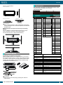
1
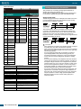
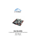
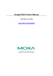
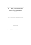
Ver.1.02 N Series for USB Multifunction DAQ Unit (8ch AI, 2ch AO, 16ch DIO) AIO-120802LN-USB This product is a USB2.0-compliant analog I/O unit that extends the analog I/O function of USB port of PCs. Compact design not restricting installation location (188.0(W) x 78.0(D) × 30.5(H)) makes it easy to install the product within the panel or device using DIN rail mounting jigs, or on the floor or wall. Windows driver library is supplied. Possible to be used as a data recording device for LabVIEW, with dedicated libraries. * Specifications, color and design of the products are subject to change without notice. Features Multi-function Analog I/O can be implemented in a compact system. The series consists of two different models from which you can select the best model to suit your application. This product contains the analog input (12bit, 8ch), analog output (12bit, 2ch). This model includes bi-directional digital inputs / outputs (16points, TTL level) and a counter (32bit 1ch, TTL level). You can select the input/output by the application software in eight signals units. Analog I/O can be synchronized with an internal timer or external clock. Analog I/O can both be performed at fixed time intervals and synchronized with an external signal. Digital filter function to prevent wrong recognition of external signal chattering is provided. This product has analog input / output control signal, digital input signal and digital filter function to prevent it from chattering in counter input signal. (Counter gate signal) Buffer memory available for background processing independent of software The boards include buffer memory (1K Word each for analog input and output) which can be used in either FIFO or ring format. This allows analog I/O to be performed independently of the operating state of the PC or software. Software-based calibration function Calibration of analog input/output can be all performed by software. Apart from the adjustment information prepared before shipment, additional adjustment information can be stored according to the use environment. Diverse installations such as screw fastening, magnet, DIN rail are possible Installation on the floor / wall /ceiling is possible by screw fastening, magnet, rubber feet, etc. In addition, DIN rail mounting mechanism is equipped as standard with the product, making it easy to install the product within the panel or the device. Easy-to-wire terminal connector adopted Adoption of terminal connector (with screws) enables to achieve easy wiring. Windows compatible driver libraries are attached. Using the attached analog I/O driver API-USBP(WDM) makes it possible to create applications of Windows. In addition, a diagnostic program by which the operations of hardware can be checked is provided. Supported to the data logger software [C-LOGGER] (Analog input only) Supporting the data logger software [C-LOGGER] that enables the graph display of recorded signal data, file saving, and dynamic transfer to the spreadsheet software program “Excel”. Plug-ins for the dedicated libraries, the board also supports MATLAB and LabVIEW. We offer a dedicated library [ML-DAQ], which allows you to use this product on MATLAB by The MathWorks as well as another dedicated library [VI-DAQ], which allows you to use the product on LabVIEW. These dedicated libraries are available, free of charge (downloadable), on our web site. Compact design not restricting installation location (188.0(W) x 78.0(D) x 30.5(H)) Compact design of 188.0(W) × 78.0(D) × 30.5(H) does not require special installation location. Compatible to USB1.1/USB2.0 Compatible to USB1.1/USB2.0 and capable to achieve high speed transfer at HighSpeed (480 Mbps). AIO-120802LN-USB 1 Ver.1.02 Support Software Support Software Item Specification Analog input Isolated specification Input type Un-Isolated Single-Ended Input or Differential Input 8channels (Single-Ended Input) 4channels (Differential Input) Bipolar 10V, 5V, 2.5V or Unipolar 0 - +10V Number of input channels Input range Absolute max. input voltage Input impedance Resolution Non-Linearity error *1 Conversion speed Buffer memory Conversion start trigger Conversion stop trigger 15V 1M or more 12bit 20LSB 5sec/ch (Max.) *2 [200KSPS]*3 1K data FIFO or 1K data RING Software / external trigger Number of sampling times / external trigger/software TTL level (Rising or falling edge can be selected by software) TTL level (Rising or falling edge can be selected by software) TTL level (Rising or falling edge can be selected by software) External start signal External stop signal External clock signal Analog output Isolated specification Un-Isolated Number of output channels Output range Output current ability Output impedance Resolution Non-Linearity error *1 Conversion speed Buffer memory Conversion start trigger Conversion stop trigger 2ch Bipolar 10V, 5V or Unipolar 0 - +10V, 0 - +5V 3mA 1 or less 12bit 20LSB 12sec (Max.) [83KSPS]*3 1K data FIFO or 1K data RING Software / external trigger Number of sampling times / external trigger/software TTL level (Rising or falling edge can be selected by software) TTL level (Rising or falling edge can be selected by software) TTL level (Rising or falling edge can be selected by software) External start signal External stop signal External clock signal Digital I/O Number of I/O Channels I/O signal level 16-bit input lines, 8-bit input/output lines, 16-bit output lines (programmable) TTL level (positive logic) Counter Number of channels 1channels Counting system Up count Max. count FFFFFFFFh (Binary data, 32bit) Number of external inputs Number of external outputs Frequency response TTL level : 2 (Gate/Up)ch, Gate (High level), Up (Rising edge) TTL level : 1ch, Count match output (positive logic, pulse output) 5MHz (Max.) USB Bus specification USB Specification 2.0/1.1 standard USB transfer rate 12Mbps (Full-speed), 480Mbps (High-speed) *4 Power supply Bus power Windows version of analog I/O driver API-AIO(WDM) [Stored on the bundled CD-ROM driver library API-USBP(WDM)] It is the library software, and which supplies command of hardware produced by our company in the form of standard Win32 API function (DLL). Using programming languages supporting Win32API functions, such as Visual Basic and Visual C++ etc., you can develop high-speed application software with feature of hardware produced by our company. In addition, you can verify the operation of hardware using Diagnostic programs. < Operating environment > OS Windows 7, Server 2008, Vista, XP, Server 2003 .etc Adaptation language Visual Basic, Visual C++, Visual C# .etc You can download the updated version from the CONTEC’s Web site (http://www.contec.com/product/device/apiusbp/). For more details on the supported OS, applicable language and new information, please visit the CONTEC’s Web site. Data Logger Software C-LOGGER [Stored on the bundled CD-ROM driver library API-USBP(WDM)] C-LOGGER is a data logger software program compatible with our analog I/O products. This program enables the graph display of recorded signal data, zoom observation, file saving, and dynamic transfer to the spreadsheet software “Excel”. No troublesome programming is required. CONTEC provides download services (at http://www.contec.com/clogger) to supply the updated drivers. For details, refer to the C-LOGGER Users Guide or our website. < Operating environment > OS Windows 7, Vista, XP, Server 2003 Data acquisition VI library for LabVIEW VI-DAQ (Available for downloading (free of charge) from the CONTEC web site.) This is a VI library to use in National Instruments LabVIEW. VI-DAQ is created with a function form similar to that of LabVIEW's Data Acquisition VI, allowing you to use various devices without complicated settings. See http://www.contec.com/vidaq/ for details and download of VI-DAQ. Common section Connector 10 pin (screw-terminal) plug header x5 Number of terminals used at 127 terminals (Max.) *5 the same time Power consumption (Max.) 5VDC 450mA Operating condition *6 0 - 50C, 10 - 90%RH (No condensation) Physical dimensions (mm) 180(L) x 140(D) x 34(H) (No protrusions) Weight 300g Attached cable length USB Cable 1.8m Certification RoHS,FCC,VCCI *1: A linearity error approximately 0.1% of full-range may occur when operated at 0ºC or 50ºC ambient temperature. *2: The required time is indicated in the analog to digital translation of one channel. When AD of two or more channels is converted, time of the a few minutes of the channel is necessary. Conversion time = Number of conversion channelsx2 *3: SPS = Samplings Per Second. The number of data that can be converted in one second is shown. *4 : The USB transfer speed depends on the host PC environment used (OS and USB host controller). *5 : As a USB hub is also counted as one device, you cannot just connect 127 USB terminals. *6 : To suppress the heating, ensure that there are spaces for ventilation (about 5cm) around this product. AIO-120802LN-USB 2 Ver.1.02 Packing List Unit (AIO-120802LN-USB) …1 USB cable (1.8m) …1 USB cable attachment on the main unit’s side (For Mini B connector side) …1 First step guide …1 I/O connector …5 Rubber feet …4 Magnet …2 CD-ROM *1 [API-USBP(WDM)] …1 Installation Method Mounting on a DIN Rail Mounting procedure (1) Push the fixing hook up using a slotted screwdriver to make it unlockable. *1 The CD-ROM contains the driver software and User’s Guide (this guide) Block Diagram (2) Hook the product from the upper part of the DIN rail, and press the lower part on to the DIN rail. (3) Push the fixing hook up using a slotted screwdriver to make it lockable. Removal procedure (1) Pull down the fixing hook of the unit to unlock it. Physical Dimensions (2) With the fixing hook unlocked, pull the lower part of this unit toward you. (3) By lifting this unit, you can easily remove it from the DIN rail. AIO-120802LN-USB 3 Ver.1.02 Desktop Installation Using the rubber feet When required to mount the product on the desktop, mount it on a horizontal platform. The rubber feet can be mounted in their mounting holes as shown in the following figure. Wall Installation To mount the product on the wall, purchase the commercially available screw (fitting for 3.5) separately. To remove the magnet, slide the magnet in the direction of arrow 1 as shown in the following figure, and then lift it out in the direction of arrow 2. Mounting onto the steel wall Mount the product directly onto the steel wall. Pull it gently after mounting to confirm that it will not drop off from the body. Installation Conditions Installation Using the Magnet Attaching the magnet supplied with the product makes it easy to mount or remove the product on or from a metal surface such as steel desk or partition. Installation orientation It is possible to mount it in the orientations shown in the following figure. Other orientations would cause problems in usage, such as inadequate heat dissipation. DIN rail fixation CAUTION - Do not let the magnet go near objects that can be affected by magnetic fields, such as monitors and floppy disks. - If the product is shifted while mounted on the steel surface, the surface paint may be scratched. - When using the magnet, stack connection is not possible. Mounting/ removing the magnet To mount the magnet, press down the entire length of the magnet into its mounting hole while pushing the magnet in the direction of arrow 1. Next, slide the magnet in the direction of arrow 2 to fix it in position. AIO-120802LN-USB Vertical installation Horizontal installation Installation on a ceiling 4 Ver.1.02 Signal Layout Screws / magnet fixation Vertical installation The unit can be connected to an external device using 10-pin connectors that is provided on the unit face. Single-Ended Input Horizontal installation Installation on a ceiling CAUTION When using the product in a high temperature environment, cool it by blowing air even when the temperature is within the specified range. Spacing between the system unit and any surrounding objects Secure a distance of at least 50mm between the top of the main unit (single use) and any surrounding objects. Do not locate the unit in a fully enclosed housing. Signal name Meaning Signal name Meaning Signal name AI00 Analog Input 00 DGND DigitalGround DIO00 AI01 Analog Input 01 AOSTA AI02 Analog Input 02 AOSTP AI03 Analog Input 03 AOCLK Analog Ground AGND (for AI) AI04 Analog Input 04 Analog Input 05 CNT G AI06 Analog Input 06 RES AI07 Analog Input 07 CNT C Analog Ground (for AI) AO00 Trigger Input AO External Sampling Clock Input DigitalGround Counter Output Counter Gate Control Input Reserved Counter Up Clock Input DigitalGround DIO02 DIO03 DGND DIO04 DIO05 DIO06 DIO07 DGND DIO09 (for AO) Analog Output 01 DIO10 Analog Ground AGND DIO01 DIO08 Analog Ground AO01 DIO11 (for AO) N.C. N.C. DGND DGND Digital Ground DIO12 AI External Start AISTA AICLK DIO13 Trigger Input AI External Stop AISTP DIO14 Trigger Input AI External Sampling DGND When connecting the unit to an external device, you can use the supplied connector plug. For wiring, strip off approximately 7 mm of the covered part of a wire rod and then insert it to the opening. After the insertion, secure the wire rod with screws. Compatible wires are AWG 28 - 16. DGND Trigger Input AO External Stop Analog Output 00 AGND Connecting an Interface Connector CNT O AI05 AGND Connection Method DGND AO External Start DIO15 Clock Input DigitalGround DGND Meaning Digital Input/Output 00 Digital Input/Output 01 Digital Input/Output 02 Digital Input/Output 03 Digital Ground Digital Input/Output 04 Digital Input/Output 05 Digital Input/Output 06 Digital Input/Output 07 DigitalGround Digital Input/Output 08 Digital Input/Output 09 Digital Input/Output 10 Digital Input/Output 11 DigitalGround Digital Input/Output 12 Digital Input/Output 13 Digital Input/Output 14 Digital Input/Output 15 DigitalGround Analog Input 00 Analog Input 07 Analog input signal. The numbers correspond to channel numbers. Analog Ground (for AI) Common analog ground for analog input signals. Analog Output 00 Analog Output 01 Analog output signal. The numbers correspond to channel numbers. Analog Ground (for AO) Common analog ground for analog output signals. AI External Start Trigger External trigger input for starting analog input sampling. Input AI External Stop Trigger Input External trigger input for stopping analog input sampling. AI External Sampling Clock External sampling clock input for analog input. Input AO External Start Trigger External trigger input for starting analog output sampling. Input AO External Stop Trigger External trigger input for stopping analog output sampling. Input AO External Sampling Clock External sampling clock input for analog output. Input Digital Input / Output 00 Digital input / Output signal. Digital Input / Output 15 Digital Output00 - Digital Output 03 Counter Gate Control Input Counter Up Clock Input Counter Output Digital output signal. Gate control input signal for counter. Count-up clock input signal for counter. Count match output signal for counter. Digital Ground Common digital ground for digital I/O signals, external trigger inputs, external sampling clock inputs, and counter I/O signals. Reserved N.C. Reserved pin. No connection to this pin. CAUTION Removing the connector plug by grasping the cable can break the wire. AIO-120802LN-USB 5 Ver.1.02 Differential Input Analog Input Signal Connection The procedure for connecting analog signals depends on whether the analog input signals are single-ended or differential. The sections below describe how to connect the signals using flat cable and shielded cable. Signal name Meaning AI00 Analog Input 00[+] AI01 Analog Input 00[- ] Signal name DGND AOSTA AI02 Analog Input 01[+] AOSTP AI03 Analog Input 01[- ] AOCLK Analog Ground AGND (for AI) AI04 Analog Input 02[+] AI05 Analog Input 02[- ] AI06 Analog Input 03[+] AI07 Analog Input 03[- ] Analog Ground AGND (for AI) AO00 Meaning DigitalGround AO External Start Trigger Input AO External Stop Trigger Input AO External Sampling Clock Input DIO02 DIO03 DGND CNT O Counter Output DIO04 CNT G RES CNT C DGND Counter Gate Control Input Reserved Counter Up Clock Input DigitalGround DIO05 DIO06 DIO07 DGND DIO08 DIO09 (for AO) Analog Output 01 DIO10 Analog Ground AGND DIO01 DigitalGround Analog Ground AO01 DIO00 DGND Analog Output 00 AGND Signal name DIO11 (for AO) N.C. N.C. DGND DGND Digital Ground DIO12 AI External Start AISTA Trigger Input AI External Stop AISTP AICLK DIO13 DIO14 Trigger Input AI External Sampling DGND DIO15 Clock Input DigitalGround DGND Single-ended Input Meaning Digital Input/Output 00 Digital Input/Output 01 Digital Input/Output 02 Digital Input/Output 03 Digital Ground Digital Input/Output 04 Digital Input/Output 05 Digital Input/Output 06 The following figure shows an example of shield cable connection. Use shielded cable if the distance between the signal source and unit is long or if you want to provide better protection from noise. For each analog input channel on interface connector, connect the core wire to the signal line and connect the shielding to ground. Digital Input/Output 07 DigitalGround Digital Input/Output 08 Digital Input/Output 09 Digital Input/Output 10 Digital Input/Output 11 DigitalGround Digital Input/Output 12 Digital Input/Output 13 Digital Input/Output 14 Digital Input/Output 15 DigitalGround Analog Input 00 Analog Input 03 Analog input signal. The numbers correspond to channel numbers. Analog Ground (FOR AI) Common analog ground for analog input signals. Analog Output 00 Analog Output 01 Analog output signal. The numbers correspond to channel numbers. Analog Ground (FOR AO) Common analog ground for analog output signals. AI External Start Trigger External trigger input for starting analog input sampling. Input AI External Stop Trigger Input External trigger input for stopping analog input sampling. AI External Sampling Clock External sampling clock input for analog input. Input AO External Start Trigger External trigger input for starting analog output Input sampling.trigger input for stopping analog output AO External Stop Trigger External Input sampling. AO External Sampling Clock External sampling clock input for analog output. Input Digital Input/Output 00 Digital input/Output signal. Digital Input/Output 15 Counter Gate Control Input Counter Up Clock Input Counter Output Gate control input signal for counter. Count-up clock input signal for counter. Count match output signal for counter. Digital Ground Common digital ground for digital I/O signals, external trigger inputs, external sampling clock inputs, and counter I/O signals. Reserved N.C. Reserved pin. No connection to this pin. AIO-120802LN-USB The following figure shows an example of flat cable connection. Connect separate signal and ground wires for each analog input channel on interface connector. CAUTION - If the signal source contains over 500 kHz signals, the signal may affect the cross-talk noise between channels. - If the unit and the signal source receive noise or the distance between the unit and the signal source is too long, data may not be input properly. - An input analog signal should not exceed the maximum input voltage (relate to the product analog ground). If it exceeds the maximum voltage, the unit may be damaged. - Connect all the unused analog input channels to analog ground. - In the channel switching, the multiplexer does the electrical charge and discharge on the internal capacitor according to the signal voltage. Therefore, the voltage from the previous switching state may go into the next channel. It might cause the error of the signal source action. If this occurs, insert a high-speed amplifier as a buffer between the signal source and the analog input pin to reduce the fluctuation. - An input pin may fail to obtain input data normally when the signal source connected to the pin has high impedance. If this is the case, change the signal source to one with lower output impedance or insert a high-speed amplifier buffer between the signal source and the analog input pin to reduce the effect. 6 Ver.1.02 Differential Input The following figure shows an example of flat cable connection. For each analog input channel on interface connector, connect the "+" input to the signal and connect the "-" input to the signal source ground. Also connect the analog ground on the unit to the signal source ground. The following figure shows an example of shielded cable connection. Use shielded cable if the distance between the signal source and unit is long or if you want to provide better protection from noise. For each analog input channel on interface connector, connect the "+" input to the signal and connect the "-" input to the signal source ground. Also connect the analog ground on the unit and the signal source ground to the shielding. - - - - CAUTION If the signal source contains over 500 kHz signals, the signal may affect the cross-talk noise between channels. When the analog ground is not connected, the conversion data is not determined. If the unit and the signal source receive noise or the distance between the unit and the signal source is too long, data may not be input properly. An input analog signal should not exceed the maximum input voltage (relate to the unit analog ground). If it exceeds the maximum voltage, the unit may be damaged. Connect all the unused analog input channels to analog ground. In the channel switching, the multiplexer does the electrical charge and discharge on the internal capacitor according to the signal voltage. Therefore, the voltage from the previous switching state may go into the next channel. It might cause the error of the signal source action. If this occurs, insert a high-speed amplifier as a buffer between the signal source and the analog input pin to reduce the fluctuation. An input pin may fail to obtain input data normally when the signal source connected to the pin has high impedance. If this is the case, change the signal source to one with lower output impedance or insert a high-speed amplifier buffer between the signal source and the analog input pin to reduce the effect. Analog Output Signal Connection This section shows how to connect the analog output signal by using a flat cable or a shield cable. The following figure shows an example of flat cable connection. Connect the signal source and ground to the interface connector analog output. The following figure shows an example of shield cable connection. Use shield cable if the distance between the signal source and this product is long or if you want to provide better protection from noise. For the interface connector analog output, connect the core wire to the signal line and connect the shielding to ground. CAUTION - If this product or the connected wire receives noise, or the distance between this product and the target is long, data may not be outputted properly. - For analog output signal, the current capacity is ±3mA (Max.). Check the specification of the connected device before connecting this product. - Do not short the analog output signal to analog ground, digital ground, and/or power line. Doing so may damage this product. - Do not connect an analog output signal to any other analog output, either on this product or on an external device, as this may cause a fault on this product. - Analog output signal outputs hundreds of micro voltages when USB cable is inserted. Connecting I/O Signals The following sections show examples of how to connect digital I/O signals. All the I/O signals are TTL level, and input or output can be set in 8 bit unit by software. I/O Circuit External circuit Unit Vcc 74LV245 10k INPUT/OUTPUT GND AIO-120802LN-USB GND 7 Ver.1.02 Example of Connection DIO00 Unit side DGND Switch DIO08 2k LED DGND When switch is "ON", the corresponding bit is "0". When switch is "OFF" in contrast, the corresponding bit is "1". When "1" is output to a relevant bit, the corresponding LED comes on. When "0" is output to the bit, in contrast, the LED goes out. CAUTION Take care not to short the outputs to digital ground as this may cause a fault. Counter signals and Control signals Connection Counter signals and Control signals Connection The following sections show examples of how to connect counter I/O signals, and other control I/O signals (external trigger input signals, sampling clock input signals, etc.). All the counter I/O signals and control signals are TTL level signals. About the counter input control signal Counter Gate Control Input (refer to the user’s manual chapter 3 Connector Pin Assignment) acts as an input that validate or invalidate the input of an external clock for the counter. This function enables the control of an external clock input for the counter. The external clock for the counter is effective when input is "High” and invalid when input is "Low". If unconnected, it is a pull-up in this product and remains "High". Therefore the external clock for the counter is effective when the counter gate control input is not connected. CAUTION - Do not short the output signals to analog ground, digital ground, and/or power line. Doing so may damage the product. - If connected to each output, a pull-up resistor must be about 10k to pull up with a 5V power source. - Each input accepts 5V TTL signals. Reference For the operation timings for control signal input, see the user’s manual - “Control Signal Timings” in Chapter 6 “Hardware”. AIO-120802LN-USB 8